2017 Elsys AG www.elsys-instruments.com 1
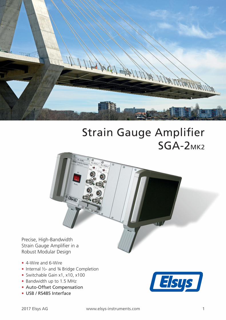
Strain Gauge AmplifierSGA-2MK2
Precise, High-BandwidthStrain Gauge Amplifier in aRobust Modular Design
• 4-Wire and 6-Wire• Internal ½- and ¾ Bridge Completion• Switchable Gain x1, x10, x100• Bandwidth up to 1.5 MHz• Auto-Offset Compensation• USB / RS485 Interface
2017 Elsys AG www.elsys-instruments.com 2
SGA Channel 1
SGA Channel 2
RG
Vex
VSense
Vbridge
cont
rol
+/-
Manual GainSwitch
50
110
100
Output
G
Control RS485/USB(Box Version only)
RS485Auto Offset Ch. 1
RG R2
R3R4
Vex
VSense
Vbridge
cont
rol
+/-50
Output
G
G= 1 10 100
G= 1 10 100
ADC
ADC
Aut
o-O
ffse
tAut
o-O
ffse
t
5 V / 10 V
Auto Offset Ch. 2
Man
ual C
onfig
.
Example: Standard Bridge 6-Wire
Example: Three-Wire Internal Quarter Bridge
RS485 RS485/USB(Amp-BU unit)
High Speed Data Acquisition Solutions
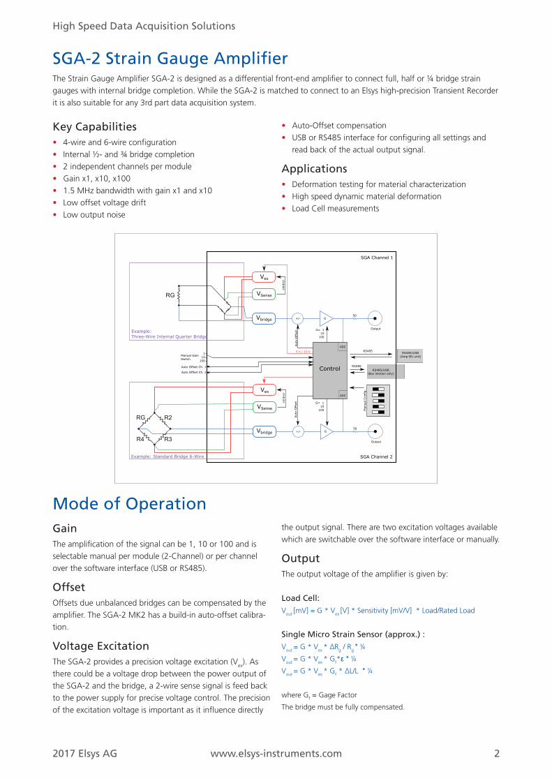
SGA-2 Strain Gauge AmplifierThe Strain Gauge Amplifier SGA-2 is designed as a differential front-end amplifier to connect full, half or ¼ bridge strain gauges with internal bridge completion. While the SGA-2 is matched to connect to an Elsys high-precision Transient Recorder it is also suitable for any 3rd part data acquisition system.
Key Capabilities• 4-wire and 6-wire configuration• Internal ½- and ¾ bridge completion• 2 independent channels per module• Gain x1, x10, x100• 1.5 MHz bandwidth with gain x1 and x10• Low offset voltage drift• Low output noise
• Auto-Offset compensation• USB or RS485 interface for configuring all settings and
read back of the actual output signal.
Applications• Deformation testing for material characterization• High speed dynamic material deformation • Load Cell measurements
GainThe amplification of the signal can be 1, 10 or 100 and is selectable manual per module (2-Channel) or per channel over the software interface (USB or RS485).
OffsetOffsets due unbalanced bridges can be compensated by the amplifier. The SGA-2 MK2 has a build-in auto-offset calibra-tion.
Voltage Excitation The SGA-2 provides a precision voltage excitation (Vex). As there could be a voltage drop between the power output of the SGA-2 and the bridge, a 2-wire sense signal is feed back to the power supply for precise voltage control. The precision of the excitation voltage is important as it influence directly
the output signal. There are two excitation voltages available which are switchable over the software interface or manually.
OutputThe output voltage of the amplifier is given by:
Load Cell:Vout [mV] = G * Vex [V] * Sensitivity [mV/V] * Load/Rated Load
Single Micro Strain Sensor (approx.) :Vout = G * Vex * ∆Rg / Rg * ¼Vout = G * Vex * Gf*ε * ¼ Vout = G * Vex * Gf * ∆L/L * ¼
where Gf = Gage Factor
The bridge must be fully compensated.
Mode of Operation
2017 Elsys AG www.elsys-instruments.com 3
SGA-2-P/7 MK2 Module with 2 channels as plug-in to a 19“ Rack
chassis
SGA-2-Box/7 MK2 Alu-box ca. 104 x 165 x 35 mm
Configurable Modes 6-Wire, 4-Wire, Internal ½ Bridge, Internal ¾ Bridge
Gain (switch selectable) x1, x10, x100
Input stage Differential Amplifier
Bandwidth 1.5 MHz (G=1, 10), 600 kHz (G=100)
Input Impedance 2 x 1 MΩ ca. 25 pF to GND
Input Bias Current < ±60 nA
Offset Voltage
(related to output, *1)
< ± ( 0.3 + 0.02 * Gain ) mV
Offset Voltage Drift
(related to output)
< ± ( 30 + 1 * Gain ) uV/°C
Gain Error < ± 0.1%
Output Impedance 50 Ω ±0.5%
Max. Output Voltage Swing ±10 V (no Load)
±5 V (Load = 50 Ω)
Max. Input Voltage
(Protected Input Range)
max. ±42 V (Signal Inputs)
max. ±2 V (Excitation Voltage Pins)
Excitation Voltage 10 V or 5 V, ±0.1%
Configurable by Dip-Switches or Software
Note: *1) after 1 h Warm-Up Time at Tamb = 25°C
Max. Load of Excitation Voltage 90 mA
Asymmetry of internal ½ Bridge max. ±0.1% ( = 5 mV @ 10 V )
Power Supply 12 VDC ± 10%, max. 6 W per 2 Ch
Operating Temperature 0 to 45 °C
Storage Temperature -20 to 60 °C
Rel. Humidity < 80 % ( up to 31 °C ) decreasing to
< 50% at 31 to 45 °C
Max. Operating Altitude 2’000 m
Input Connector Type Lemo 7-pol. or 16-pol Lemo
Output BNC
Output Noise
Int. ½ Bridge Off Int. ½ Bridge On
Bandwidth Bandwidth
Gain 100 kHz Full 100 kHz Full
1 0.03 mVrms
0.3 mVpp
0.3 mVrms
1.5 mVpp
0.05 mVrms
0.8 mVpp
0.4 mVrms
6 mVpp
10 0.08 mVrms
0.6 mVpp
0.5 mVrms
5 mVpp
0.3 mVrms
2.5 mVpp
2.5 mVrms
40 mVpp
100 0.6 mVrms
4 mVpp
1.5 mVrms
12 mVpp
3 mVrms
20 mVpp
10 mVrms
150 mVpp
High Speed Data Acquisition Solutions
Specification
Strain Gauge Amplifier Order InformationModel Unit Description Interface
Amp-BU-10 MK2 Rack Case for max. 5 SGA-2 modules (10 channels) USB
Amp-BU-24 MK2 Rack Case for max. 12 SGA-2 modules (24 channels), USB Interface USB
SGA2-P/7 MK2 2-channel strain gauge amplifier module, input connector 7-pol Lemo, rack-mount RS485
SGA2-P/16 MK2 2-channel strain gauge amplifier module, input connector 16-pol Lemo, rack-mount RS485
SGA2-Box/7 MK2 2-channel strain gauge amplifier in external box, input connector 7-pol Lemo USB
SGA2-Box/16 MK2 2-channel strain gauge amplifier in external box, input connector 16-pol Lemo USB
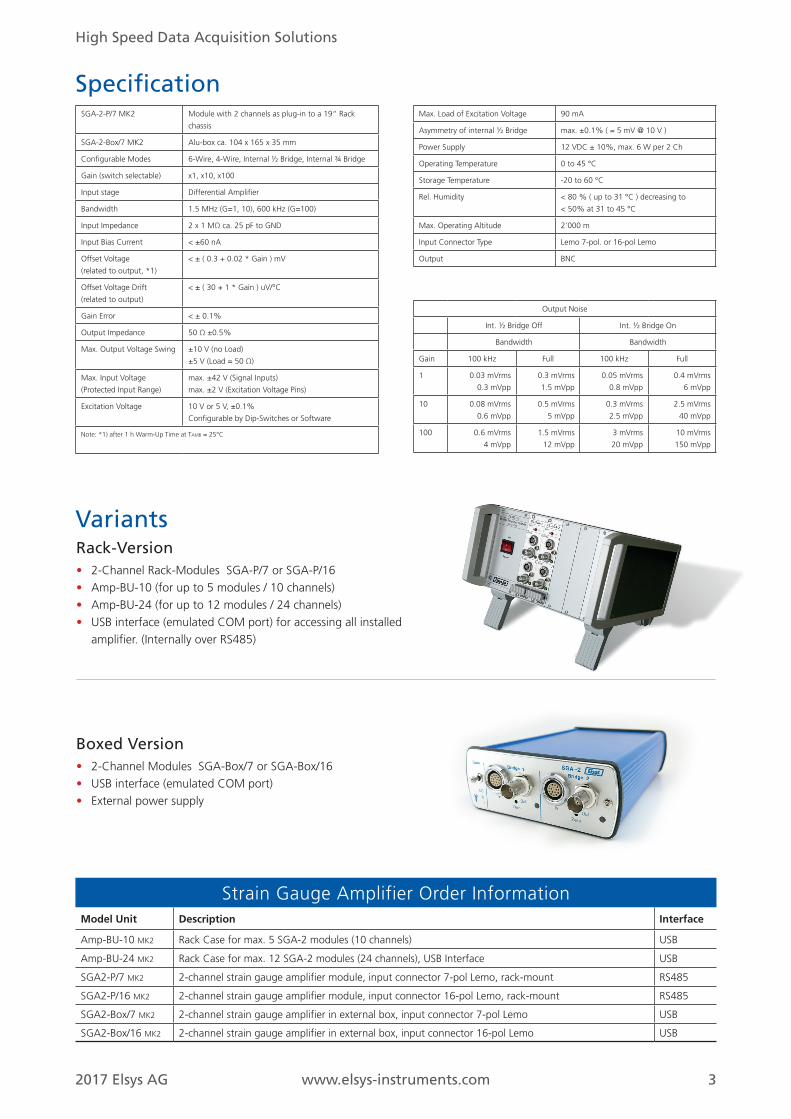
VariantsRack-Version• 2-Channel Rack-Modules SGA-P/7 or SGA-P/16• Amp-BU-10 (for up to 5 modules / 10 channels)• Amp-BU-24 (for up to 12 modules / 24 channels)• USB interface (emulated COM port) for accessing all installed
amplifier. (Internally over RS485)
Boxed Version• 2-Channel Modules SGA-Box/7 or SGA-Box/16• USB interface (emulated COM port)• External power supply

2017 Elsys AG www.elsys-instruments.com 4
High Speed Data Acquisition Solutions
Elsys AGElsys AG
Mellingerstrasse 12
CH-5443 Niederrohrdorf
Switzerland
Phone: +41 56 496 01 55
Email: [email protected]
www.elsys-instruments.com