STARTING SYSTEM
–STARTING SYSTEMST–1
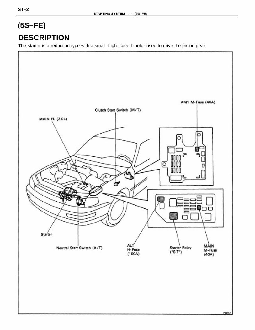
DESCRIPTIONThe starter is a reduction type with a small, high–speed motor used to drive the pinion gear.
(5S–FE)
–STARTING SYSTEM (5S–FE)ST–2

OPERATIONWhen the ignition switch is turned to START position, current flows from terminal 50 to the coilof the solenoid and the plunger is pulled by the magnetic force of the coil. When the plunger ispulled to the left, the contact plate of the plunger allows current from the battery to flow directlyfrom terminal 30 to the motor, and the starter rotates.When the engine is running and the ignition switch is returned to ON, the magnetic force of thecoil disappears and the contact plate of the plunger is returned to its original position by thereturn spring. Battery voltage no longer flows from terminal 30, so the motor stops.
SYSTEM CIRCUIT
–STARTING SYSTEM (5S–FE)ST–3

ON–VEHICLE INSPECTIONNOTICE: Before changing the starter, check the following Items again:• Connector connection• Accessory Installation, e.g.: theft deterrent system
PREPARATIONSST (SPECIAL SERVICE TOOLS)
09286–46011 Injection Pump Spline ShaftPuller
RECOMMENDED TOOLS
09820–00030 Alternator Rear Bearing Replacer
09082–00050 TOYOTA Electrical Tester set
EQUIPMENT
Armature front bearing
Magnetic finger
Vernier calipers Commutator, Brush
Torque wrench
Armature bearing
Dial indicator
Sandpaper
Brush springPull scale
Commutator
Commutator
V – block
–STARTING SYSTEM (5S–FE)ST–4

STARTER REMOVAL
1. DISCONNECT NEGATIVE (–) TERMINAL CABLEFROM BATTERYCAUTION: Work must be started after 90 seconds fromthe time the ignition switch is turned to the ’LOCK’position and the negative (–) terminal cable Is discon–nected from the battery.
STARTERCOMPONENTS FOR REMOVAL ANDINSTALLATION
2. w/ CRUISE CONTROL SYSTEM:REMOVE BATTERY
–STARTING SYSTEM (5S–FE)ST–5
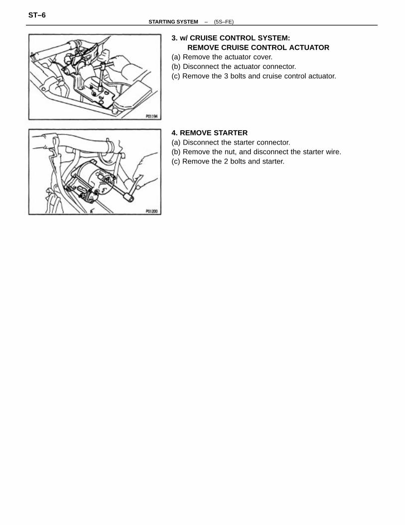
3. w/ CRUISE CONTROL SYSTEM:REMOVE CRUISE CONTROL ACTUATOR
(a) Remove the actuator cover.(b) Disconnect the actuator connector.(c) Remove the 3 bolts and cruise control actuator.
4. REMOVE STARTER(a) Disconnect the starter connector.(b) Remove the nut, and disconnect the starter wire.(c) Remove the 2 bolts and starter.
–STARTING SYSTEM (5S–FE)ST–6

COMPONENTS FOR DISASSEMBLY ANDASSEMBLY
–STARTING SYSTEM (5S – FE)ST–7
STARTER DISASSEMBLY
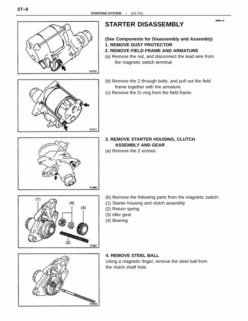
(See Components for Disassembly and Assembly)1. REMOVE DUST PROTECTOR2. REMOVE FIELD FRAME AND ARMATURE(a) Remove the nut, and disconnect the lead wire from
the magnetic switch terminal.
(b) Remove the following parts from the magnetic switch:(1) Starter housing and clutch assembly(2) Return spring(3) Idler gear(4) Bearing
(b) Remove the 2 through bolts, and pull out the fieldframe together with the armature.
(c) Remove the O–ring from the field frame.
4. REMOVE STEEL BALLUsing a magnetic finger, remove the steel ball fromthe clutch shaft hole.
3. REMOVE STARTER HOUSING, CLUTCHASSEMBLY AND GEAR
(a) Remove the 2 screws.
–STARTING SYSTEM (5S–FE)ST–8

STARTER INSPECTION AND REPAIRArmature Coil1. INSPECT COMMUTATOR FOR OPEN CIRCUITUsing an ohmmeter, check that there is continuitybetween the segments of the commutator.If there is no continuity between any segment, replacethe armature.
REMOVE BRUSH HOLDER(a) Remove the 2 screws, 2 O–rings and end cover from
the field frame.(b) Remove the O–ring from the field frame.
2. INSPECT COMMUTATOR FOR GROUNDUsing an ohmmeter, check that there is no continuitybetween the commutator and armature coil core.If there is continuity, replace the armature.
(c) Using a screwdriver, hold the spring back and discon–nect the brush from the brush holder.Disconnect the 4 brushes, and remove the brushholder.
6. REMOVE ARMATURE FROM FIELD FRAME
–STARTING SYSTEM (5S–FE)ST–9

3. INSPECT COMMUTATOR4R DIAMETERUsing a vernier caliper, measure the commutator di–ameter.
Standard diameter:30 mm (1.18 In.)
Minimum diameter:29 mm (1.14 in.)
If the diameter is less than minimum, replace thearmature.
4. INSPECT UNDERCUT DEPTHCheck that the undercut depth is clean and free offoreign materials. Smooth out the edge.
Standard undercut depth:0.6 mm (0.024 in.)
Minimum undercut depth:0.2 mm 10.008 In.)
If the undercut depth is less than minimum, correct itwith a hacksaw blade.
2. INSPECT COMMUTATOR CIRCLE RUNOUT(a) Place the commutator on V – blocks.(b) Using a dial gauge, measure the circle runout.
Maximum circle runout:0.05 mm (0.0020 in.)
If the circle runout is greater than maximum, correct iton a lathe.
Commutator1. INSPECT COMMUTATOR FOR DIRTY AND BURNT
SURFACESIf the surface is dirty or burnt, correct it with sandpa–per (No.400) or on a lathe.
Field Frame (Field Coil)
1. INSPECT FIELD COIL FOR OPEN CIRCUITUsing an ohmmeter, check that there is continuitybetween the lead wire and field coil brush lead.If there is no continuity, replace the field frame.
–STARTING SYSTEM (5S–FE)ST–10
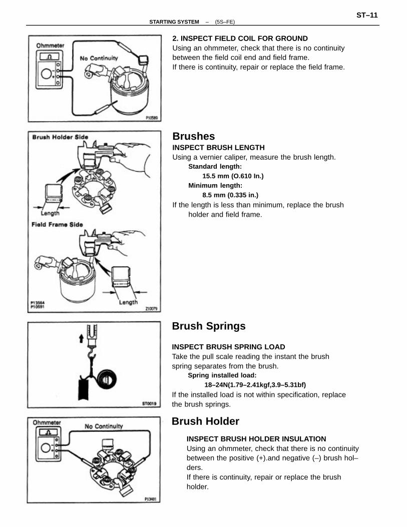
BrushesINSPECT BRUSH LENGTHUsing a vernier caliper, measure the brush length.
Standard length:15.5 mm (O.610 In.)
Minimum length:8.5 mm (0.335 in.)
If the length is less than minimum, replace the brushholder and field frame.
Brush Springs
INSPECT BRUSH SPRING LOADTake the pull scale reading the instant the brushspring separates from the brush.
Spring installed load:18–24N(1.79–2.41kgf,3.9–5.31bf)
If the installed load is not within specification, replacethe brush springs.
INSPECT BRUSH HOLDER INSULATIONUsing an ohmmeter, check that there is no continuitybetween the positive (+).and negative (–) brush hol–ders.If there is continuity, repair or replace the brushholder.
2. INSPECT FIELD COIL FOR GROUNDUsing an ohmmeter, check that there is no continuitybetween the field coil end and field frame.If there is continuity, repair or replace the field frame.
Brush Holder
–STARTING SYSTEM (5S–FE)ST–11
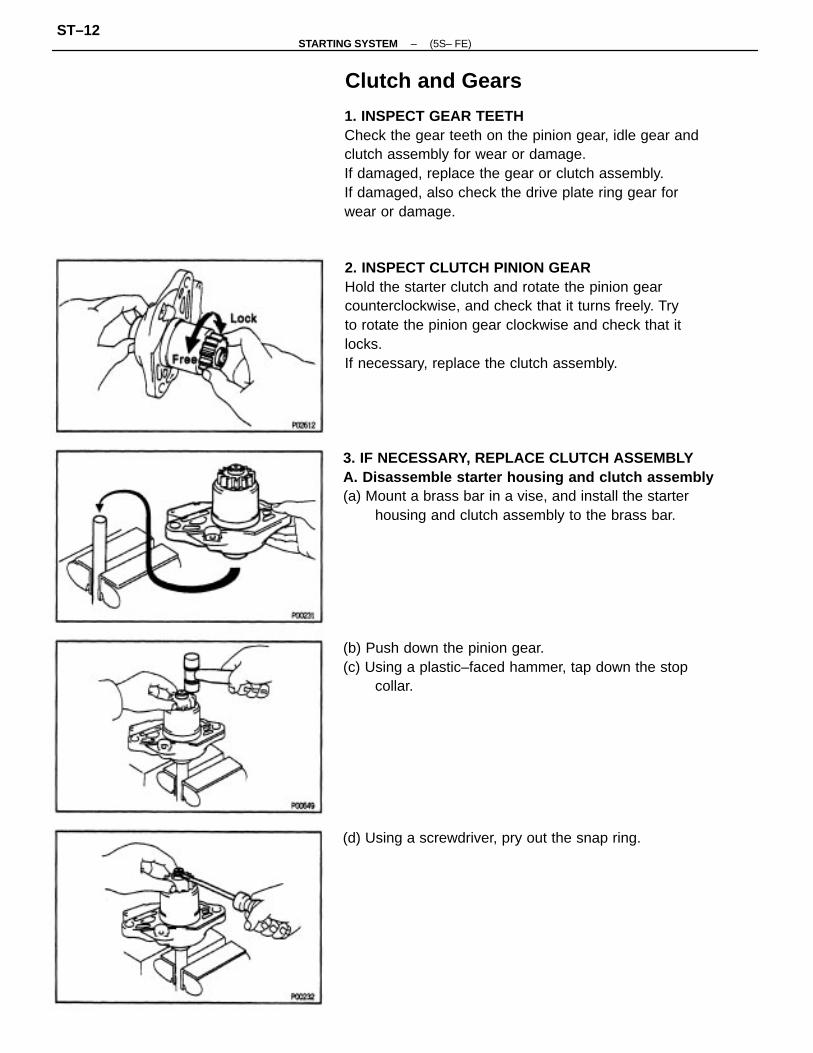
2. INSPECT CLUTCH PINION GEARHold the starter clutch and rotate the pinion gearcounterclockwise, and check that it turns freely. Tryto rotate the pinion gear clockwise and check that itlocks.If necessary, replace the clutch assembly.
1. INSPECT GEAR TEETHCheck the gear teeth on the pinion gear, idle gear andclutch assembly for wear or damage.If damaged, replace the gear or clutch assembly.If damaged, also check the drive plate ring gear forwear or damage.
3. IF NECESSARY, REPLACE CLUTCH ASSEMBLYA. Disassemble starter housing and clutch assembly(a) Mount a brass bar in a vise, and install the starter
housing and clutch assembly to the brass bar.
(b) Push down the pinion gear.(c) Using a plastic–faced hammer, tap down the stop
collar.
(d) Using a screwdriver, pry out the snap ring.
Clutch and Gears
–STARTING SYSTEM (5S– FE)ST–12
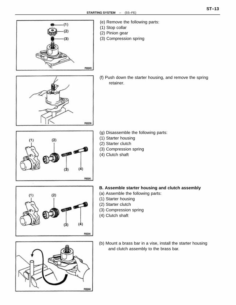
B. Assemble starter housing and clutch assembly(a) Assemble the following parts:(1) Starter housing(2) Starter clutch(3) Compression spring(4) Clutch shaft
(g) Disassemble the following parts:(1) Starter housing(2) Starter clutch(3) Compression spring(4) Clutch shaft
(e) Remove the following parts:(1) Stop collar(2) Pinion gear(3) Compression spring
(b) Mount a brass bar in a vise, install the starter housingand clutch assembly to the brass bar.
(f) Push down the starter housing, and remove the springretainer.
–STARTING SYSTEM (5S–FE)ST–13

Bearings1. INSPECT REAR BEARINGSTurn each bearing by hand while applying inwardforce.If resistance is felt or the bearing sticks, replace thebearing.
(c) Push down the starter housing, and install the follow–ing parts:
(1) Spring retainer(2) Compression spring(3) Pinion gear(4) Stop collar
(h) Remove the starter housing and clutch assembly fromthe brass bar.
(i) Using a plastic–faced hammer, tap the clutch shaftand install the stop collar onto the snap ring.
(d) Push down the pinion gear.(e) Using snap ring pliers, install a new snap ring.
(f) Using pliers, compress the snap ring.(g) Check that the snap ring fits correctly.
–STARTING SYSTEM (5S–FE)ST–14
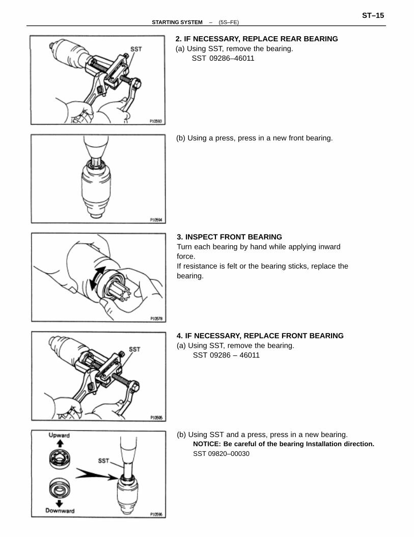
3. INSPECT FRONT BEARINGTurn each bearing by hand while applying inwardforce.If resistance is felt or the bearing sticks, replace thebearing.
(b) Using SST and a press, press in a new bearing.NOTICE: Be careful of the bearing Installation direction.SST 09820–00030
4. IF NECESSARY, REPLACE FRONT BEARING(a) Using SST, remove the bearing.
SST 09286 – 46011
2. IF NECESSARY, REPLACE REAR BEARING(a) Using SST, remove the bearing.
SST 09286–46011
(b) Using a press, press in a new front bearing.
–STARTING SYSTEM (5S–FE)ST–15

STARTER ASSEMBLY
(See Components for Disassembly and Assembly)HINT: Use high–temperature grease to lubricate thebearings and gears when assembling the starter.1. PLACE ARMATURE INTO FIELD FRAMEApply grease to the armature bearings, and insert thearmature into the field frame.
2. INSTALL BRUSH HOLDER(a) Place the brush holder in position on the armature.(b) Using a screwdriver, hold the brush spring back, and
connect the brush into the brush holder. Connect the4 brushes.NOTICE: Check that the positive (+) lead wires are notgrounded.
Magnetic Switch
1. PERFORM PULL–IN COIL OPEN CIRCUIT TESTUsing an ohmmeter, check that there is continuitybetween terminals 50 and C.If there is no continuity, replace the magnetic switch.
2. PERFORM HOLD–IN COIL OPEN CIRCUIT TESTUsing an ohmmeter, check that there is continuitybetween terminal 50 and the switch body.If there is no continuity, replace the magnetic switch.
(c) Place a new O–ring in position on the field frame.
–STARTING SYSTEM (5S– FE)ST–16

(c) Place the following parts in position on the starterhousing:
(1) Idler gear(2) Retainer
4. INSTALL STARTER HOUSING, CLUTCH ASSEM–BLY AND GEAR(a) Apply grease to the return spring.(b) Insert the return spring into the magnetic switch hole.
(d) Install a new O–ring to the screw.(e) Install the end cover to the field frame with the 2
screws.Torque: 1.5 N ⋅m (15 kgf ⋅cm, 13 in. ⋅Ibf)
(d) Install the starter housing to the magnetic switch withthe 2 screws.Torque: 5.9 N ⋅m (60 kgf ⋅cm. 62 in. ⋅lbf)
3. INSERT STEEL BALL INTO CLUTCH SHAFT HOLE(a) Apply grease to the steel ball.(b) Insert the steel ball into the clutch shaft hole.
–STARTING SYSTEM (5S–FE)ST–17

(c) Install the field frame and armature assembly with the2 through bolts.Torque: 6.9 N ⋅m (60 kgf ⋅cm, 52 in. ⋅lbf)
(d) Connect the lead wire to terminal C, and install thenut.Torque: 7.9 N ⋅m (81 kgf ⋅cm, 70 In. ⋅Ibf)
5. INSTALL FIELD FRAME AND ARMATUREASSEMBLY
(a) Place a new O–ring in position on the field frame.
(b) Align the protrusion of the field frame with the cutoutof the magnetic switch.
6. INSTALL DUST PROTECTOR
–STARTING SYSTEM (5S– FE)ST–18

STARTER PERFORMANCE TESTNOTICE: These tests must be performed within 3 to 5seconds to avoid burning out the coil.
1. PERFORM PULL–IN TEST(a) Disconnect the field coil lead wire from terminal C.(b) Connect the battery to the magnetic switch as shown.
Check that the clutch pinion gear moves outward.If the clutch pinion gear does not move, replace themagnetic switch assembly.
2. PERFORM HOLD–IN TESTWith battery connected as above with the clutchpinion gear out, disconnect the negative (–) lead fromterminal C. Check that the pinion gear remains out.If the clutch pinion gear returns inward, replace themagnetic switch assembly.
4. PERFORM NO–LOAD PERFORMANCE TEST(a) Connect the battery and ammeter to the starter as
shown.(b) Check that the starter rotates smoothly and steadily
with the pinion gear moving out. Check that the am–meter shows the specified current.Specified current:
90 A or less at11.6V
3. INSPECT CLUTCH PINION GEAR RETURNDisconnect the negative (–) lead from the switchbody.Check that the clutch pinion gear returns inward.If the clutch pinion gear does not return, replace themagnetic switch assembly.
–STARTING SYSTEM (5S–FE)ST–19
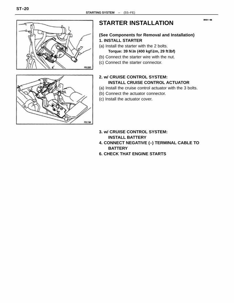
STARTER INSTALLATION
(See Components for Removal and Installation)1. INSTALL STARTER(a) Install the starter with the 2 bolts.
Torque: 39 N ⋅m (400 kgf ⋅cm, 29 ft ⋅lbf)
(b) Connect the starter wire with the nut.(c) Connect the starter connector.
3. w/ CRUISE CONTROL SYSTEM:INSTALL BATTERY
4. CONNECT NEGATIVE (–) TERMINAL CABLE TOBATTERY
6. CHECK THAT ENGINE STARTS
2. w/ CRUISE CONTROL SYSTEM:INSTALL CRUISE CONTROL ACTUATOR
(a) Install the cruise control actuator with the 3 bolts.(b) Connect the actuator connector.(c) Install the actuator cover.
–STARTING SYSTEM (5S–FE)ST–20
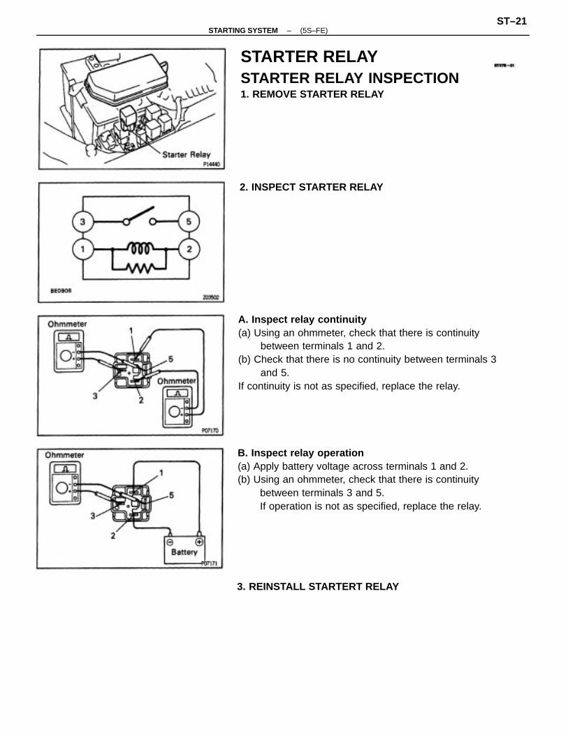
A. Inspect relay continuity(a) Using an ohmmeter, check that there is continuity
between terminals 1 and 2.(b) Check that there is no continuity between terminals 3
and 5.If continuity is not as specified, replace the relay.
B. Inspect relay operation(a) Apply battery voltage across terminals 1 and 2.(b) Using an ohmmeter, check that there is continuity
between terminals 3 and 5.If operation is not as specified, replace the relay.
STARTER RELAYSTARTER RELAY INSPECTION1. REMOVE STARTER RELAY
3. REINSTALL STARTERT RELAY
2. INSPECT STARTER RELAY
–STARTING SYSTEM (5S–FE)ST–21

PARK/NEUTRAL POSITION (PNP) SWITCH(A/T)(See page AX–92)
CLUTCH START SWITCH(M/T)(See page CL–7)
SERVICE SPECIFICATIONSSERVICE DATA
Rated voltage and output powerNo–load characteristics
Spring installed loadCommutatorDiameter
TORQUE SPECIFICATIONS
End cover x Starter housing (Through bolt)
Starter housing x Magnetic switch
Lead wire x Terminal C of starter
End cover x Brush holder
Starter x Transaxle
Undercut depth
Pert tightened
Brush length
Circle runout
Starter
–STARTING SYSTEM (5S–FE)ST–22

DESCRIPTIONThe starter is a reduction type with a small, high–speed motor used to drive the pinion gear.
(1 MZ–FE)
–STARTING SYSTEM (1MZ – FE)ST–23

OPERATIONWhen the ignition switch is turned to START position, current flows from terminal 50 to the coilof the solenoid and the plunger is pulled by the magnetic force of the coil. When the plunger ispulled to the left, the contact plate of the plunger allows current from the battery to flow directlyfrom terminal 30 to the motor, and the starter rotates.When the engine is running and the ignition switch is returned to ON, the magnetic force of thecoil disappears and the contact plate of the plunger is returned to its original position by thereturn spring. Battery voltage no longer flows from terminal 30, so the motor stops.
SYSTEM CIRCUIT
–STARTING SYSTEM (1MZ – FE)ST–24

ON –VEHICLE INSPECTIONNOTICE: Before changing the starter, check the following items again:• Connector connection• Accessory installation, e.g.: theft deterrent system
PREPARATIONSST (SPECIAL SERVICE TOOLS)
09286–46011 Injection Pump Spline ShaftPuller
09820–00030 Alternator Rear Bearing Replacer
RECOMMENDED TOOLS09082–00050 TOYOTA Electrical Tester set
EQUIPMENT
Armature front bearing
Magnetic finger
Vernier calipers Commutator, Brush
Armature bearing
Torque wrench
Dial indicator
Brush spring
Sandpaper
Commutator
Commutator
Commutator
Pull scale
V–block
Steel bell
–STARTING SYSTEM (1MZ – FE)ST–25

STATER REMOVAL
(See Components for Removal and installation)1. DISCONNECT NEGATIVE (–) TERMINAL CABLE
FROM BATTERYCAUTION: Work must be started after 90 seconds fromthe time the ignition switch is turned to the ”LOCK”position and the negative (–) terminal cable is dis–connected from the battery.
2. w/ CRUISE CONTROL SYSTEM:REMOVE BATTERY AND TRAY
STARTERCOMPONENTS FOR REMOVAL ANDINSTALLATION
–STARTING SYSTEM (1MZ – FE)ST–26
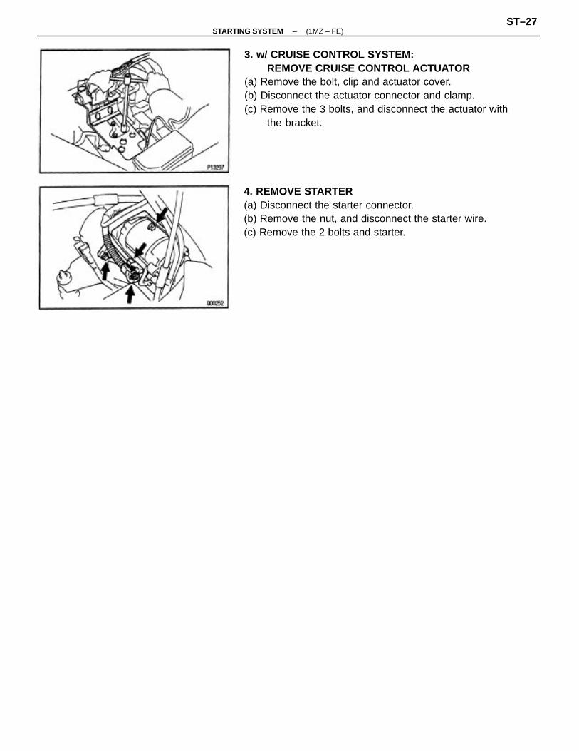
3. w/ CRUISE CONTROL SYSTEM:REMOVE CRUISE CONTROL ACTUATOR
(a) Remove the bolt, clip and actuator cover.(b) Disconnect the actuator connector and clamp.(c) Remove the 3 bolts, and disconnect the actuator with
the bracket.
4. REMOVE STARTER(a) Disconnect the starter connector.(b) Remove the nut, and disconnect the starter wire.(c) Remove the 2 bolts and starter.
–STARTING SYSTEM (1MZ – FE)ST–27

COMPONENTS FOR DISASSEMBLY ANDASSEMBLY
–STARTING SYSTEM (1MZ – FE)ST–28

STARTER DISASSEMBLY
(See Components for Disassembly and Assembly)1. REMOVE DUST PROTECTOR2. REMOVE FIELD FRAME AND ARMATURE(a) Remove the nut, and disconnect the lead wire fromthe magnetic switch terminal.
(b) Remove the following parts from the magnetic switch:(1) Starter housing and clutch assembly(2) Return spring(3) Idler gear(4) Bearing
(b) Remove the 2 through bolts, and pull out the fieldframe together with the armature.
(c) Remove the O–ring from the field frame.
3. REMOVE STARTER HOUSING, CLUTCHASSEMBLY AND GEAR
(a) Remove the 2 screws.
4. REMOVE STEEL BALLUsing a magnetic finger, remove the steel ball fromthe clutch shaft hole.
–STARTING SYSTEM (1MZ – FE)ST–29

STARTER INSPECTION AND REPAIRArmature Coil
1. INSPECT COMMUTATOR FOR OPEN CIRCUITUsing an ohmmeter, check that there is continuitybetween the segments of the commutator.If there is no continuity between any segment, replacethe armature.
5. REMOVE BRUSH HOLDER(a) Remove the 2 screws, 2 O–rings and end cover from
the field frame.(b) Remove the O–ring from the field frame.
2. INSPECT COMMUTATOR FOR GROUNDUsing an ohmmeter, check that there is no continuitybetween the commutator and armature coil core.If there is continuity, replace the armature.
(c) Using a screwdriver, hold the spring back and discon–nect the brush from the brush holder.Disconnect the 4 brushes, and remove the brushholder.
6. REMOVE ARMATURE FROM FIELD FRAME
–STARTING SYSTEM (1MZ – FE)ST–30

3. INSPECT COMMUTATOR DIAMETERUsing a vernier caliper, measure the commutator diameter.
Standard diameter:30.0 mm 0.181 In.)
Minimum diameter:29.0 mm (1.142 In.)
If the diameter is less than minimum, replace thearmature.
4. INSPECT UNDERCUT DEPTHCheck that the undercut depth is clean and free offoreign materials. Smooth out the edge.
Standard undercut depth:0.6 mm (0.024 In.)
Minimum undercut depth:0.2 mm (0.008 In.)
If the undercut depth is less than minimum, correct itwith a hacksaw blade.
2. INSPECT COMMUTATOR CIRCLE RUNOUT(a) Place the commutator on V – blocks.(b) Using a dial gauge, measure the circle runout.
Maximum circle runout:0.05 mm (0.0020 in.)
If the circle runout is greater than maximum, correct iton a lathe.
Field Frame (Field Coil)
1. INSPECT FIELD COIL FOR OPEN CIRCUITUsing an ohmmeter, check that there is continuitybetween the lead wire and field coil brush lead.If there is no continuity, replace the field frame.
Commutator1. INSPECT COMMUTATOR FOR DIRTY AND BURNT
SURFACESIf the surface is dirty or burnt, correct it with sandpaper(No.400) or on a lathe.
–STARTING SYSTEM (1MZ – FE)ST–31

Brushes
INSPECT BRUSH LENGTHUsing a vernier caliper, measure the brush length.
Standard length:15.5 mm (O.610 In.)
Minimum length:8.5 mm (0.335 In.)
If the length is less than minimum, replace the brushholder and field frame.
Brush Springs
INSPECT BRUSH SPRING LOADTake the pull scale reading the instant the brushspring separates from the brush.
Spring installed load:18 – 24 N (1.79 – 2.41 kgf. 3.9 – 5.3 Ibf)
If the installed load is not within specification, replacethe brush springs.
Brush Holder
INSPECT BRUSH HOLDER INSULATIONUsing an ohmmeter, check that there is no continuitybetween the positive (+) and negative (–) brush hol–ders.If there is continuity, repair or replace the brushholder.
2. INSPECT FIELD COIL FOR GROUNDUsing an ohmmeter, check that there is no continuitybetween the field coil end and field frame.If there is continuity, repair or replace the field frame.
–STARTING SYSTEM (1MZ – FE)ST–32

Clutch and Gears
1. INSPECT GEAR TEETHCheck the gear teeth on the pinion gear, idler gear andclutch assembly for wear or damage.If damaged, replace the gear or clutch assembly.If damaged, also check the drive plate ring gear forwear or damage.
2. INSPECT CLUTCH PINION GEARHold the starter clutch and rotate the pinion gearcounterclockwise, and check that it turns freely. Tryto rotate the pinion gear clockwise and check that itlocks.If necessary, replace the clutch assembly.
3. IF NECESSARY, REPLACE CLUTCH ASSEMBLYA. Disassembly of starter housing and clutch assembly(a) Mount a brass bar in a vise, and install the starter
housing and clutch assembly to the brass bar.
(b) Push down the pinion gear.(c) Using a plastic–faced hammer, tap down the stop
collar.
(d) Using a screwdriver, pry out the snap ring.
–STARTING SYSTEM (1MZ – FE)ST–33
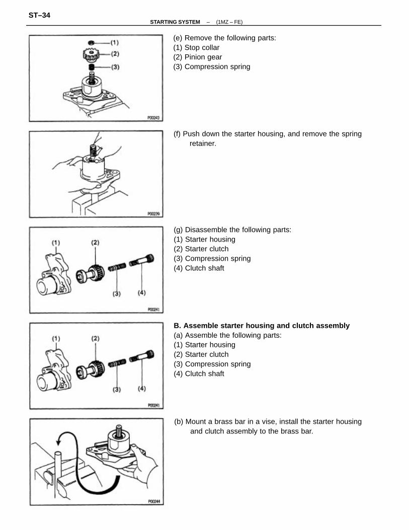
B. Assemble starter housing and clutch assembly(a) Assemble the following parts:(1) Starter housing(2) Starter clutch(3) Compression spring(4) Clutch shaft
(g) Disassemble the following parts:(1) Starter housing(2) Starter clutch(3) Compression spring(4) Clutch shaft
(e) Remove the following parts:(1) Stop collar(2) Pinion gear(3) Compression spring
(b) Mount a brass bar in a vise, install the starter housingand clutch assembly to the brass bar.
(f) Push down the starter housing, and remove the springretainer.
–STARTING SYSTEM (1MZ – FE)ST–34
Bearings
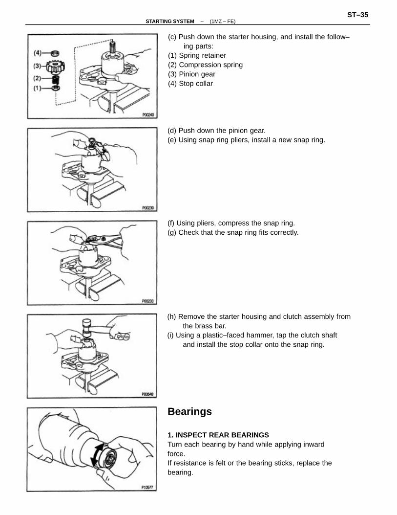
1. INSPECT REAR BEARINGSTurn each bearing by hand while applying inwardforce.If resistance is felt or the bearing sticks, replace thebearing.
(c) Push down the starter housing, and install the follow–ing parts:
(1) Spring retainer(2) Compression spring(3) Pinion gear(4) Stop collar
(h) Remove the starter housing and clutch assembly fromthe brass bar.
(i) Using a plastic–faced hammer, tap the clutch shaftand install the stop collar onto the snap ring.
(d) Push down the pinion gear.(e) Using snap ring pliers, install a new snap ring.
(f) Using pliers, compress the snap ring.(g) Check that the snap ring fits correctly.
–STARTING SYSTEM (1MZ – FE)ST–35

3. INSPECT FRONT BEARINGTurn each bearing by hand while applying inwardforce.If resistance is felt or the bearing sticks, replace thebearing.
(b) Using SST and a press, press in a new bearing.NOTICE: Be careful of the bearing Installation direction.SST 09820–00030
4. IF NECESSARY, REPLACE FRONT BEARING(a) Using SST, remove the bearing.
SST 09286–46011
2. IF NECESSARY, REPLACE REAR BEARING(a) Using SST, remove the bearing.
SST 09286–46011
(b) Using a press, press in a new front bearing.
–STARTING SYSTEM (1MZ – FE)ST–36
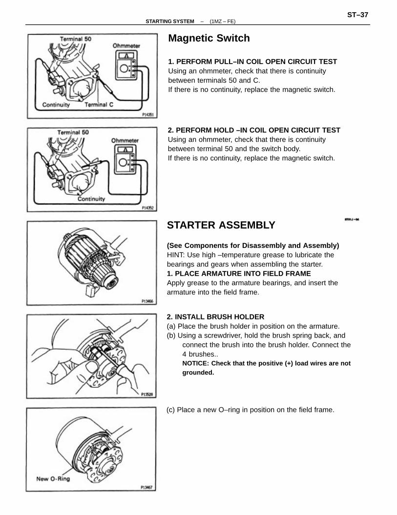
STARTER ASSEMBLY
(See Components for Disassembly and Assembly)HINT: Use high –temperature grease to lubricate thebearings and gears when assembling the starter.1. PLACE ARMATURE INTO FIELD FRAMEApply grease to the armature bearings, and insert thearmature into the field frame.
2. INSTALL BRUSH HOLDER(a) Place the brush holder in position on the armature.(b) Using a screwdriver, hold the brush spring back, and
connect the brush into the brush holder. Connect the4 brushes..NOTICE: Check that the positive (+) load wires are notgrounded.
Magnetic Switch
1. PERFORM PULL–IN COIL OPEN CIRCUIT TESTUsing an ohmmeter, check that there is continuitybetween terminals 50 and C.If there is no continuity, replace the magnetic switch.
2. PERFORM HOLD –IN COIL OPEN CIRCUIT TESTUsing an ohmmeter, check that there is continuitybetween terminal 50 and the switch body.If there is no continuity, replace the magnetic switch.
(c) Place a new O–ring in position on the field frame.
–STARTING SYSTEM (1MZ – FE)ST–37

(c) Place the following parts in position on the starterhousing:
(1) Idler gear(2) Retainer
4. INSTALL STARTER HOUSING, CLUTCH ASSEM–BLY AND GEAR(a) Apply grease to the return spring.(b) Insert the return spring into the magnetic switch hole.
(d) Install a new 0 – ring to the screw.(e) Install the end cover to the field frame with the 2
screws.Torque: 1.5 N ⋅m (15 kgf ⋅cm, 13 in. ⋅Ibf)
(d) Install the starter housing to the magnetic switch withthe 2 screws.Torque: 5.9 N ⋅m (60 kgf ⋅cm, 52 In. ⋅Ibf)
3. INSERT STEEL BALL INTO CLUTCH SHAFT HOLE(a) Apply grease to the steel ball.(b) Insert the steel ball into the clutch shaft hole.
–STARTING SYSTEM (1MZ – FE)ST–38

(c) Install the field frame and armature assembly with the2 through bolts.Torque: 5.9 N ⋅m (60 kgf ⋅cm. 52 in. ⋅Ibf)
5. INSTALL FIELD FRAME AND ARMATUREASSEMBLY(a) Place a new 0 – ring in position on the field frame.
(d) Connect the lead wire to terminal C, and install thenut.Torque: 7.9 N ⋅m (87 kgf ⋅cm, 70 in. ⋅lbf)
(b) Align the protrusion of the field frame with the cutoutof the magnetic switch.
–STARTING SYSTEM (1MZ – FE)ST–39

STARTER PERFORMANCE TEST
NOTICE: These tests must be performed within 3 to 5seconds to avoid burning out the coil.
1. PERFORM PULL–IN TEST(a) Disconnect the field coil lead wire from terminal C.(b) Connect the battery to the magnetic switch as shown.
Check that the clutch pinion gear moves outward.If the clutch pinion gear does not move, replace themagnetic switch assembly.
2. PERFORM HOLD–IN TESTWith battery connected as above with the clutchpinion gear out, disconnect the negative (–) lead fromterminal C. Check that the pinion gear remains out.If the clutch pinion gear returns inward, replace themagnetic switch assembly.
4. PERFORM NO –LOAD PERFORMANCE TEST(a) Connect the battery and ammeter to the starter as
shown.(b) Check that the starter rotates smoothly and steadily
with the pinion gear moving out. Check that the am–meter shows the specified current.Specified current:
90 A or less at 11.5 V
3. INSPECT CLUTCH PINION GEAR RETURNDisconnect the negative (–) lead from the switchbody.Check that the clutch pinion gear returns inward.If the clutch pinion gear does not return, replace themagnetic switch assembly.
–STARTING SYSTEM (1MZ – FE)ST–40
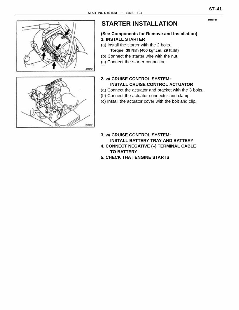
(See Components for Remove and Installation)1. INSTALL STARTER(a) Install the starter with the 2 bolts.
Torque: 39 N ⋅m (400 kgf ⋅cm. 29 ft ⋅lbf)
(b) Connect the starter wire with the nut.(c) Connect the starter connector.
2. w/ CRUISE CONTROL SYSTEM:INSTALL CRUISE CONTROL ACTUATOR
(a) Connect the actuator and bracket with the 3 bolts.(b) Connect the actuator connector and clamp.(c) Install the actuator cover with the bolt and clip.
3. w/ CRUISE CONTROL SYSTEM:INSTALL BATTERY TRAY AND BATTERY
4. CONNECT NEGATIVE (–) TERMINAL CABLETO BATTERY
5. CHECK THAT ENGINE STARTS
STARTER INSTALLATION
–STARTING SYSTEM (1MZ – FE)ST–41

STARTER RELAYSTARTER RELAY INSPECTION1. DISCONNECT NEGATIVE (–) TERMINAL CABLEFROM BATTERY
CAUTION: Work must be started after 90 seconds fromthe time the ignition switch Is turned to the ’LOCK’position and the negative (–) terminal cable is discon–nected from the battery.
3. INSPECT STARTER RELAYA. Inspect relay continuity(a) Using an ohmmeter, check that there is continuity
between terminals 1 and 2.(b) Check that there is no continuity between terminals 3
and 5.If continuity is not as specified, replace the relay.
B. Inspect relay operation(a) Apply battery voltage across terminals 1 and 2.(b) Using an ohmmeter, check that there is continuity
between terminals 3 and 5.If operation is not as specified, replace the relay.
2. REMOVE STARTER RELAYLOCATION: In the engine compartment relay box.Remove the relay box cover and starter relay.
4. REINSTALL STARTER RELAY6. RECONNECT NEGATIVE (–) TERMINAL CABLE
TO BATTERY
–STARTING SYSTEM (1MZ – FE)ST–42

PARK NEUTRAL POSITION (PNP) SWITCH(See page AX–116)
SERVICE SPECIFICATIONSSERVICE DATA
Rated voltage and output powerNo–load characteristics
TORQUE SPECIFICATIONS
Spring installed loadCommutatorDiameter
Starter housing x Magnetic switch
Field frame x Armature assembly
Lead wire x Terminal C of starter
End cover x Field frame
Starter mounting bolt
Undercut depth
Part tightened
Brush length
Circle runout
Starter
–STARTING SYSTEM (1MZ – FE)ST–43


![BULETIN 5S - jupem.gov.my1].pdf · SPU SISIH 5S SUSUN 5S Aktiviti Sapu di Pejabat sedang dijalankan SAPU 5S. KARTOGRAFI Aktiviti menyisih majalah dan buletin Aktiviti menyisih di](https://static.cupdf.com/doc/110x72/5cfc613188c993756e8c159c/buletin-5s-jupemgovmy-1pdf-spu-sisih-5s-susun-5s-aktiviti-sapu-di-pejabat.jpg)