


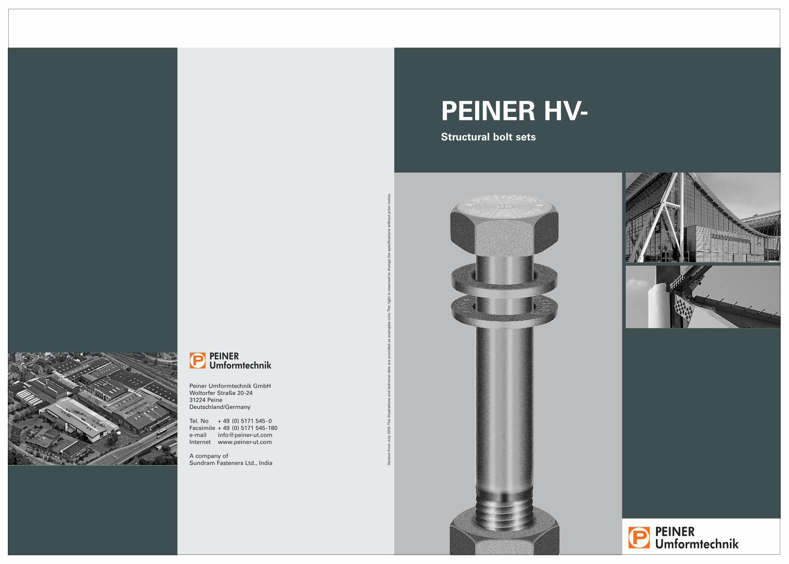
PEINER HV-Structural bolt sets
Peiner Umformtechnik GmbHWoltorfer Straße 20-2431224 PeineDeutschland/Germany
Tel. No + 49 (0) 5171 545-0Facsimile + 49 (0) 5171 545-180e-mail [email protected] www.peiner-ut.com
A company ofSundram Fasteners Ltd., India Ve
rsio
n f
rom
Ju
ly 2
010.
Th
e ill
ust
rati
on
s an
d t
ech
nic
al d
ata
are
pro
vid
ed a
s ex
amp
les
on
ly. T
he
rig
ht
is r
eser
ved
to
ch
ang
e th
e sp
ecif
icat
ion
s w
ith
ou
t p
rio
r n
oti
ce.

PEINER Umformtechnik is a company ofIndian Sundram Fasteners Limited (SFL).Sundram is a member of the TVS Group, one of India’s largest automotive suppliers.The Peine factory of PEINER Umformtechnikhas produced bolts, nuts and other fasteningelements for steel structures and bridges,fasteners for wind turbines as well as high-end automotive parts for well-known car and truck makers throughout the worldfor more than 80 years.
Our key accounts provide technology supportfor our customers on all aspects of fasteningtechnology, from the selection of fastener elements, the design of the fastening pointsor calculation and installation. By cooperationwith universities and colleges under researchagreements and by active involvement withstandardisation bodies, such as national (DIN)and international (CEN, ISO) standardizationcommittees, we are always abreast of thestate-of-the-art and help advance it. We makeour customers aware of changes in productstandards, calculation or installation provisions and other features in seminarsand training courses.
Through wholesale channels, which providethe logistics services, PEINER Umformtechniksupplies high-strength HV-bolt-sets and HV-fit-bolt-sets complying with DIN EN 14399-4,DIN EN 14399-6 and DIN EN 14399-8 to thesteel construction industry.
PEINER high-strength preloaded (HV) bolt-sets are preferably used in slip-re-sistant connections, flexurally rigid plate connections, shear type connections and in ring flange connections of wind turbines.
As construction elements serving a safetyfunction, these fasteners must comply withstrict quality requirements. Consequently, we have installed high-precision standardsand invested heavily in quality assurance.Each Peiner HV-bolt and HV-nut carries a code– a serial number – to make the end product traceable right down to the batch of inputmaterial. This code adds transparency to theproduction process and, at the same time, isan expression of our quality demand. Accor-ding to DIN 18800-7:2008-11, this makes testcertificates 3.1 which DIN EN 10204 requiresfor HV-bolts, unnecessary. However, test certificates 3.1 will still be issued on request.
PEINER HV-sets are available ex stock in thestandard size range from M12 to M36. Largersizes up to M64, especially for installation in wind turbines, complying with DASt-guide-line 021 and the corresponding PEINER com-pany standard, are also available.
Corrosion protection by hot dip galvanization
Hot dip galvanizing provides efficient andlong-life corrosion protection even in poten-tially aggressive atmospheres. Depending onthe aggressive media, a zinc coat of 50 to 70 µm thickness alloyed with the base material can protect the full function of thebolted connection for many years (Figure 1).
Based on scientific findings and empiricaldata gained through many years in the industry, hot dip galvanizing is applied underdefined conditions according to the manufac-turing guideline of Deutscher Schraubenver-band and Gemeinschaftsausschuss Verzinken.
Hot dip galvanized and black, slightly oiledHV-nuts are treated with special long-timelubrication and are ready for installation. In this state, they comply with the require-ments for preload force and tightening torque according to DIN 18800-7:2008-11.
The European HV-product standards are so called harmonized standards according to the
Construction Product Directive of theEuropean Community. On this basis, HV-setsare delivered with CE label. Therefore, nohandicaps to trading these products shouldexist or be established within the EuropeanCommunity.
As a rule, HV-sets according to DIN EN 14399-4, DIN EN 14399-6 and DIN EN 14399-8 are shipped with CE label in k-class K1 design and, in addition, comply with DIN 18800-7 for torque controlled preloading.
The components of the HV-sets, i.e., bolts,nuts and washers, are packed separately. An HV-set is a combination of bolt, nut andwasher from one manufacturer.
HV-sets can be used without restriction for all bolted structural connections common in steel construction according to the German standard DIN 18800-1 and European standard DIN EN 1993-1-8.
Leading in steel construction
PEINER HV-bolt-sets
32
200
150
100
50
0 10 20 30 40 50 60 70 80
Industrial air
Thickness of zinc coat in µm
Protection period* on years (mean)
Marine air
City air
Rural air
Indoor spaces
Figure 1
Period of protection of
zinc coatings
Source: Hot dip galvanizing specifications (5.4 Corrosions behaviour of zinc coatings exposed to atmospheric), 3rd edition 1999
*The period of protection
is not a „warranty period.“
M12 M16 M20 M22 M24 M27 M30 M36
Shank lengths ls and lg
Nominal length I
Thread end acc. to DIN 78-Ku = incompl. thread = max. 2P
Washer acc. toDIN EN 14399-6
Clamping length ∑tDetail X
Nut acc. to DIN EN 14399-4
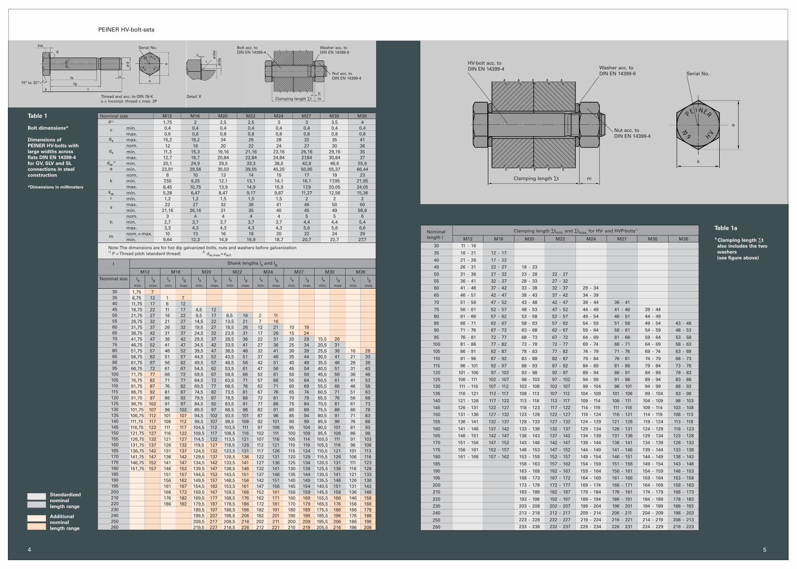
Table 1
Bolt dimensions*
Dimensions of
PEINER HV-bolts with
large widths across
flats DIN EN 14399-4
for GV, SLV and SL
connections in steel
construction
*Dimensions in millimeters
Table 1a
1) Clamping length ∑t
also includes the two
washers
(see figure above)
Bolt acc. to DIN EN 14399-4
5
Clamping length ∑tmin. and ∑tmax. for HV- and HVP-bolts1)
Standardized
nominal
length range
Additional
nominal
length range
15° to 30°
kw Serial No.
kIg
I
Is
ød
s
us
e
c
r
X
ød ød
a
PEINER HV-bolt-sets
4
mh
M12 M16 M20 M22 M24 M27 M30 M36P1)
c
da
ds
dw2)
e
k
kwr
s
h
m
l
Nominal size
3035404550556065707580859095100105110115120125130135140145150155160165170175180185190195200210220230240250260
1,75 76,75 12 1 711,75 17 6 1216,75 22 11 17 4,5 1221,75 27 16 22 9,5 17 8,5 16 2 1126,75 32 21 27 14,5 22 13,5 21 7 1631,75 37 26 32 19,5 27 18,5 26 12 21 10 1936,75 42 31 37 24,5 32 23,5 31 17 26 15 2441,75 47 36 42 29,5 37 28,5 36 22 31 20 29 15,5 2646,75 52 41 47 34,5 42 33,5 41 27 36 25 34 20,5 3151,75 57 46 52 39,5 47 38,5 46 32 41 30 39 25,5 36 16 2856,75 62 51 57 44,5 52 43,5 51 37 46 35 44 30,5 41 21 3361,75 67 56 62 49,5 57 48,5 56 42 51 40 49 35,5 46 26 3866,75 72 61 67 54,5 62 53,5 61 47 56 45 54 40,5 51 31 4371,75 77 66 72 59,5 67 58,5 66 52 61 50 59 45,5 56 36 4876,75 82 71 77 64,5 72 63,5 71 57 66 55 64 50,5 61 41 5381,75 87 76 82 69,5 77 68,5 76 62 71 60 69 55,5 66 46 5886,75 92 81 87 74,5 82 73,5 81 67 76 65 74 60,5 71 51 6391,75 97 86 92 79,5 87 78,5 86 72 81 70 79 65,5 76 56 6896,75 102 91 97 84,5 92 83,5 91 77 86 75 84 70,5 81 61 73101,75 107 96 102 89,5 97 88,5 96 82 91 80 89 75,5 86 66 78106,75 112 101 107 94,5 102 93,5 101 87 96 85 94 80,5 91 71 83111,75 117 106 112 99,5 107 98,5 106 92 101 90 99 85,5 96 76 88116,75 122 111 117 104,5 112 103,5 111 97 106 95 104 90,5 101 81 93121,75 127 116 122 109,5 117 108,5 116 102 111 100 109 95,5 106 86 98126,75 132 121 127 114,5 122 113,5 121 107 116 105 114 100,5 111 91 103131,75 137 126 132 119,5 127 118,5 126 112 121 110 119 105,5 116 96 108136,75 142 131 137 124,5 132 123,5 131 117 126 115 124 110,5 121 101 113141,75 147 136 142 129,5 137 128,5 136 122 131 120 129 115,5 126 106 118146,75 152 141 147 134,5 142 133,5 141 127 136 125 134 120,5 131 111 123151,75 157 146 152 139,5 147 138,5 146 132 141 130 139 125,5 136 116 128
151 157 144,5 152 143,5 151 137 146 135 144 130,5 141 121 133156 162 149,5 157 148,5 156 142 151 140 149 135,5 146 126 138161 167 154,5 162 153,5 161 147 156 145 154 140,5 151 131 143166 172 159,5 167 158,5 166 152 161 150 159 145,5 156 136 148176 182 169,5 177 168,5 176 162 171 160 169 155,5 166 146 158186 192 179,5 187 178,5 186 172 181 170 179 165,5 176 156 168
189,5 197 188,5 196 182 191 180 189 175,5 186 166 178199,5 207 198,5 206 192 201 190 199 185,5 196 176 188209,5 217 208,5 216 202 211 200 209 195,5 206 186 198219,5 227 218,5 226 212 221 210 219 205,5 216 196 208
min.max.max.nom.min.max.min.min.nom.min.max.min.min.max.min.nom.min.max.nom.= max.min.
1,75 2 2,5 2,5 3 3 3,5 40,4 0,4 0,4 0,4 0,4 0,4 0,4 0,40,6 0,6 0,8 0,8 0,8 0,8 0,8 0,8 15,2 19,2 24 26 28 32 35 4112 16 20 22 24 27 30 36
11,3 15,3 19,16 21,16 23,16 26,16 29,16 3512,7 16,7 20,84 22,84 24,84 27,84 30,84 3720,1 24,9 29,5 33,3 38,0 42,8 46,6 55,923,91 29,56 35,03 39,55 45,20 50,85 55,37 66,44
8 10 13 14 15 17 19 237,55 9,25 12,1 13,1 14,1 16,1 17,95 21,958,45 10,75 13,9 14,9 15,9 17,9 20,05 24,055,28 6,47 8,47 9,17 9,87 11,27 12,56 15,361,2 1,2 1,5 1,5 1,5 2 2 222 27 32 36 41 46 50 60
21,16 26,16 31 35 40 45 49 58,83 4 4 4 4 5 5 6
2,7 3,7 3,7 3,7 3,7 4,4 4,4 5,43,3 4,3 4,3 4,3 4,3 5,6 5,6 6,610 13 16 18 20 22 24 29
9,64 12,3 14,9 16,9 18,7 20,7 22,7 27,7
Note: The dimensions are for hot dip galvanized bolts, nuts and washers before galvanization1) P = Thread pitch (standard thread) 2) dw,max.=sact.
M12 M16 M20 M22 M24 M27 M30 M3630
35
40
45
50
55
60
65
70
75
80
85
90
95
100
105
110
115
120
125
130
135
140
145
150
155
160
165
170
175
180
185
190
195
200
210
220
230
240
250
260
11 - 16
16 - 21 12 - 17
21 - 26 17 - 22
26 - 31 22 - 27 18 - 23
31 - 36 27 - 32 23 - 28 22 - 27
36 - 41 32 - 37 28 - 33 27 - 32
41 - 46 37 - 42 33 - 38 32 - 37 29 - 34
46 - 51 42 - 47 38 - 43 37 - 42 34 - 39
51 - 56 47 - 52 43 - 48 42 - 47 39 - 44 36 - 41
56 - 61 52 - 57 48 - 53 47 - 52 44 - 49 41 - 46 39 - 44
61 - 66 57 - 62 53 - 58 52 - 57 49 - 54 46 - 51 44 - 49
66 - 71 62 - 67 58 - 63 57 - 62 54 - 59 51 - 56 49 - 54 43 - 48
71 - 76 67 - 72 63 - 68 62 - 67 59 - 64 56 - 61 54 - 59 48 - 53
76 - 81 72 - 77 68 - 73 67 - 72 64 - 69 61 - 66 59 - 64 53 - 58
81 - 86 77 - 82 73 - 78 72 - 77 69 - 74 66 - 71 64 - 69 58 - 63
86 - 91 82 - 87 78 - 83 77 - 82 74 - 79 71 - 76 69 - 74 63 - 68
91 - 96 87 - 92 83 - 88 82 - 87 79 - 84 76 - 81 74 - 79 68 - 73
96 - 101 92 - 97 88 - 93 87 - 92 84 - 89 81 - 86 79 - 84 73 - 78
101 - 106 97 - 102 93 - 98 92 - 97 89 - 94 86 - 91 84 - 89 78 - 83
106 - 111 102 - 107 98 - 103 97 - 102 94 - 99 91 - 96 89 - 94 83 - 88
111 - 116 107 - 112 103 - 108 102 - 107 99 - 104 96 - 101 94 - 99 88 - 93
116 - 121 112 - 117 108 - 113 107 - 112 104 - 109 101 - 106 99 - 104 93 - 98
121 - 126 117 - 122 113 - 118 112 - 117 109 - 114 106 - 111 104 - 109 98 - 103
126 - 131 122 - 127 118 - 123 117 - 122 114 - 119 111 - 116 109 - 114 103 - 108
131 - 136 127 - 132 123 - 128 122 - 127 119 - 124 116 - 121 114 - 119 108 - 113
136 - 141 132 - 137 128 - 133 127 - 132 124 - 129 121 - 126 119 - 124 113 - 118
141 - 146 137 - 142 133 - 138 132 - 137 129 - 134 126 - 131 124 - 129 118 - 123
146 - 151 142 - 147 138 - 143 137 - 142 134 - 139 131 - 136 129 - 134 123 - 128
151 - 156 147 - 152 143 - 148 142 - 147 139 - 144 136 - 141 134 - 139 128 - 133
156 - 161 152 - 157 148 - 153 147 - 152 144 - 149 141 - 146 139 - 144 133 - 138
161 - 166 157 - 162 153 - 158 152 - 157 149 - 154 146 - 151 144 - 149 138 - 143
158 - 163 157 - 162 154 - 159 151 - 156 149 - 154 143 - 148
163 - 168 162 - 167 159 - 164 156 - 161 154 - 159 148 - 153
168 - 173 167 - 172 164 - 169 161 - 166 159 - 164 153 - 158
173 - 178 172 - 177 169 - 174 166 - 171 164 - 169 158 - 163
183 - 188 182 - 187 179 - 184 176 - 181 174 - 179 168 - 173
193 - 198 192 - 197 189 - 194 186 - 191 184 - 189 178 - 183
203 - 208 202 - 207 199 - 204 196 - 201 194 - 199 188 - 193
213 - 218 212 - 217 209 - 214 206 - 211 204 - 209 198 - 203
223 - 228 222 - 227 219 - 224 216 - 221 214 - 219 208 - 213
233 - 238 232 - 237 229 - 234 226 - 231 224 - 229 218 - 223
Nominal size
ls lg ls lg ls lg ls lg ls lg ls lg ls lg ls lgmin. max. min. max. min. max. min. max. min. max. min. max. min. max. min. max.
ød
w
HV-bolt acc. to DIN EN 14399-4
Clamping length ∑t m
Washer acc. to DIN EN 14399-6
Nut acc. to DIN EN 14399-4
e
s
Serial No.
Nominal length IThread d
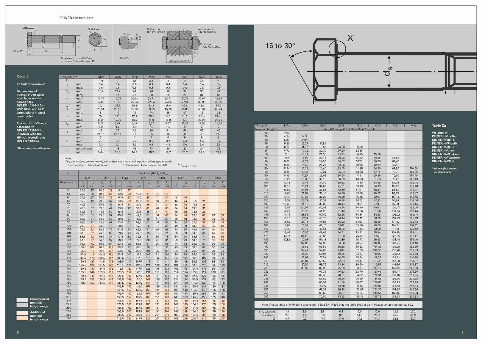
Table 2
Fit bolt dimensions*
Dimensions of
PEINER HV-fit-bolts
with large widths
across flats
DIN EN 14399-8 for
GVP, SLVP and SLP
connections in steel
construction
The nut for HVP-sets
according to
DIN EN 14399-8 is
identical with the
HV-nut according to
DIN EN 14399-4
*Dimensions in millimeters
Table 2a
Weights of
PEINER HV-bolts
DIN EN 14399-4,
PEINER HVP-bolts
DIN EN 14399-8,
PEINER HV-nuts
DIN EN 14399-4 and
PEINER HV-washers
DIN EN 14399-6
* All weights are for
guidance only
7
X
ds
PEINER HV-bolt-sets
6
M12 M16 M20 M22 M24 M27 M30 M36Weight* in kg/100 bolts with 7.85 kg//dm3
M12 M16 M20 M22 M24 M27 M30 M36
Shank lengths ls and lg
Nominal size
Standardized
nominal
length range
Additional
nominal
length range
M12 M16 M20 M22 M24 M27 M30 M36
l
Nominal size
50556065707580859095100105110115120125130135140145150155160165170175180185190195200210220230240250260
20,5 27 14,5 22 8,5 1725,5 32 19,5 27 13,5 22 12,5 21 6 1630,5 37 24,5 32 18,5 27 17,5 26 11 21 9 1935,5 42 29,5 37 23,5 32 22,5 31 16 26 14 24 9,5 2140,5 47 34,5 42 28,5 37 27,5 36 21 31 19 29 14,5 2645,5 52 39,5 47 33,5 42 32,5 41 26 36 24 34 19,5 3150,5 57 44,5 52 38,5 47 37,5 46 31 41 29 39 24,5 3655,5 62 49,5 57 43,5 52 42,5 51 36 46 34 44 29,5 41 20 3360,5 67 54,5 62 48,5 57 47,5 56 41 51 39 49 34,5 46 25 3865,5 72 59,5 67 53,5 62 52,5 61 46 56 44 54 39,5 51 30 4370,5 77 64,5 72 58,5 67 57,5 66 51 61 49 59 44,5 56 35 4875,5 82 69,5 77 63,5 72 62,5 71 56 66 54 64 49,5 61 40 5380,5 87 74,5 82 68,5 77 67,5 76 61 71 59 69 54,5 66 45 5885,5 92 79,5 87 73,5 82 72,5 81 66 76 64 74 59,5 71 50 6390,5 97 84,5 92 78,5 87 77,5 86 71 81 69 79 64,5 76 55 6895,5 102 89,5 97 83,5 92 82,5 91 76 86 74 84 69,5 81 60 73100,5 107 94,5 102 88,5 97 87,5 96 81 91 79 89 74,5 86 65 78105,5 112 99,5 107 93,5 102 92,5 101 86 96 84 94 79,5 91 70 83110,5 117 104,5 112 98,5 107 97,5 106 91 101 89 99 84,5 96 75 88115,5 122 109,5 117 103,5 112 102,5 111 96 106 94 104 89,5 101 80 93120,5 127 114,5 122 108,5 117 107,5 116 101 111 99 109 94,5 106 85 98125,5 132 119,5 127 113,5 122 112,5 121 106 116 104 114 99,5 111 90 103130,5 137 124,5 132 118,5 127 117,5 126 111 121 109 119 104,5 116 95 108135,5 142 129,5 137 123,5 132 122,5 131 116 126 114 124 109,5 121 100 113140,5 147 134,5 142 128,5 137 127,5 136 121 131 119 129 114,5 126 105 118145,5 152 139,5 147 133,5 142 132,5 141 126 136 124 134 119,5 131 110 123150,5 157 144,5 152 138,5 147 137,5 146 131 141 129 139 124,5 136 115 128
143,5 152 142,5 151 136 146 134 144 129,5 141 120 133148,5 157 147,5 156 141 151 139 149 134,5 146 125 138153,5 162 152,5 161 146 156 144 154 139,5 151 130 143158,5 167 157,5 166 151 161 149 159 144,5 156 135 148168,5 177 167,5 176 161 171 159 169 154,5 166 145 158178,5 187 177,5 186 171 181 169 179 164,5 176 155 168188,5 197 187,5 196 181 191 179 189 174,5 186 165 178198,5 207 197,5 206 191 201 189 199 184,5 196 175 188208,5 217 207,5 216 201 211 199 209 194,5 206 185 198218,5 227 217,5 226 211 221 209 219 204,5 216 195 208
min.max.max.nom.min.2)
max.2)
min.min.nom.min.max.min.min.max.min.nom.min.max.nom.= max.min.
1,75 2 2,5 2,5 3 3 3,5 40,4 0,4 0,4 0,4 0,4 0,4 0,4 0,40,6 0,6 0,8 0,8 0,8 0,8 0,8 0,8 15,2 19,2 24 26 28 32 35 4113 17 21 23 25 28 31 37
12,74 16,74 20,71 22,71 24,71 27,71 30,67 36,6712,85 16,85 20,84 22,84 24,84 27,84 30,83 36,8320,1 24,9 29,5 33,3 38,0 42,8 46,6 55,923,91 29,56 35,03 39,55 45,20 50,85 55,37 66,44
8 10 13 14 15 17 19 237,55 9,25 12,1 13,1 14,1 16,1 17,95 21,958,45 10,75 13,9 14,9 15,9 17,9 20,05 24,055,28 6,47 8,47 9,17 9,87 11,27 12,56 15,361,2 1,2 1,5 1,5 1,5 2 2 222 27 32 36 41 46 50 60
21,16 26,16 31 35 40 45 49 58,83 4 4 4 4 5 5 6
2,7 3,7 3,7 3,7 3,7 4,4 4,4 5,43,3 4,3 4,3 4,3 4,3 5,6 5,6 6,610 13 16 18 20 22 24 29
9,64 12,3 14,9 16,9 18,7 20,7 22,7 27,7
Note:The dimensions are for hot dip galvanized bolts, nuts and washers before galvanization1) P = Thread pitch (standard thread) 2) Corresponds to tolerance class b11 3) dw,max. = sact.
3035404550556065707580859095100105110115120125130135140145150155160165170175180185190195200205210215220225230235240245250255260
1,4 3,0 3,8 4,8 6,0 10,6 12,6 21,22,3 4,5 6,9 9,8 14,5 20,7 26,2 46,03,7 7,5 10,7 14,6 20,5 31,3 38,8 67,2
+ 2 HV-washers+ 1 HV-nut
∑
Note: The weights of HVP-bolts according to DIN EN 14399-8 in the table should be increased by approximately 6%.
4,504,94 9,195,39 9,985,83 10,77 17,836,28 11,56 19,07 24,60 30,606,72 12,35 20,30 26,09 32,387,16 13,14 21,53 27,58 34,15 45,907,61 13,92 22,77 29,08 35,93 48,15 61,638,05 14,71 24,00 30,57 37,70 50,39 64,408,50 15,50 25,23 32,06 39,48 52,64 67,178,94 16,29 26,46 33,55 41,25 54,89 69,95 110,509,38 17,08 27,70 35,04 43,03 57,14 72,72 114,509,83 17,87 28,93 36,54 44,81 59,38 75,50 118,4910,27 18,66 30,16 38,03 46,58 61,63 78,27 122,4910,71 19,45 31,40 39,52 48,36 63,88 81,05 126,4811,16 20,24 32,63 41,01 50,13 66,13 83,82 130,4811,60 21,03 33,86 42,50 51,91 68,37 86,60 134,4712,05 21,82 35,10 44,00 53,68 70,62 89,37 138,4712,49 22,61 36,33 45,49 55,46 72,87 92,14 142,4612,93 23,39 37,56 46,98 57,23 75,11 94,92 146,4613,38 24,18 38,80 48,47 59,01 77,36 97,69 150,4513,82 24,97 40,03 49,96 60,79 79,61 100,47 154,4514,27 25,76 41,26 51,46 62,56 81,86 103,24 158,4414,71 26,55 42,49 52,95 64,34 84,10 106,02 162,4415,15 27,34 43,73 54,44 66,11 86,35 108,79 166,4315,60 28,13 44,96 55,93 67,89 88,60 111,57 170,4316,04 28,92 46,19 57,42 69,66 90,85 114,34 174,4216,49 29,71 47,43 58,92 71,44 93,09 117,11 178,4216,93 30,50 48,66 60,41 73,22 95,34 119,89 182,4117,37 31,29 49,89 61,90 74,99 97,59 122,66 186,4117,82 32,08 51,13 63,39 76,77 99,83 125,44 190,40
32,86 52,36 64,88 78,54 102,08 128,21 194,4033,65 53,59 66,38 80,32 104,33 130,99 198,3934,44 54,83 67,87 82,09 106,58 133,76 202,3935,23 56,06 69,36 83,87 108,82 136,53 206,3836,02 57,29 70,85 85,64 111,07 139,31 210,3836,81 58,52 72,34 87,42 113,32 142,08 214,3737,60 59,76 73,84 89,20 115,57 144,86 218,3738,39 60,99 75,33 90,97 117,81 147,63 222,36
62,22 76,82 92,75 120,06 150,41 226,3663,46 78,31 94,52 122,31 153,18 230,3564,69 79,80 96,30 124,55 155,96 234,3565,92 81,30 98,07 126,80 158,73 238,3567,16 82,79 99,85 129,05 161,50 242,3468,39 84,28 101,63 131,30 164,28 246,3469,62 85,77 103,40 133,54 167,05 250,3370,86 87,26 105,18 135,79 169,83 254,33
Thread end acc. to DIN 78-Ku = incompl. thread = max. 2P
Washer acc. toDIN EN 14399-6
Clamping length ∑tDetail X
Nut acc. to DIN EN 14399-4
Bolt acc. to DIN EN 14399-8
15° to 30°
kw
k I
IsIg
ød
s
u
c
r
X
ød ø
dw
ød
a
h
m
P1)
c
da
ds
dw3)
e
k
kwr
s
h
m
ls lg ls lg ls lg ls lg ls lg ls lg ls lg ls lgmin. max. min. max. min. max. min. max. min. max. min. max. min. max. min. max.
Serial No.
s
e
15 to 30°
Categories of stuctural bolted joints
The classification of bolted connections in DIN 18800-1 was revised and a new classification adopted by DIN EN 1993-1-8. The new classification is based on the direction of force transmission in relation to the bolt longitudinal axis. Tables 3 and 4below illustrate the performance criteria,which will be explained later, and therespective classification according to DIN 18800-1, each for the serviceability limit state (GdG) and the ultimate limit state of load-bearing capacity (GdT).
Calculation of HV-bolted connections
Verification of the performance capacityof HV-connections using HV-bolts will, for some time, still be based on the Germanstandard DIN 18800-1 and also the Europeanstandard DIN EN 1993-1-8 and DIN EN 1993-1-9. So it is reasonable toconsider both verification formats and expose technically relevant differences where such differences exist.
1. Verification of bolt shear
1.1. The design value of the ultimate limitstate, Va, must not exceed the limit shear forces Va,R,d in DIN 18800-1:2008-11.
The limit shear force, Va,R,d is
Va,R,d = A . ta,R,d = A . aa. fu,b,k gM
A Shank diameter ASch, if the smooth shank is located in the shear joint. Stressed cross section ASp, of the thread part of the shank is located in the shear joint.
aa 0,55 for HV-bolts of property class 10.9, if the smooth shank is located in the shear joint.
0,44 for HV-bolts of property class 10.9, if the threaded part is located in the shear joint.
fu,b,k Typical tensile strength of the bolt material, for HV-bolt: 1000 N/mm2
gM = 1,1 partial safety factor for resistance
Additional requirements must be met for the method of proving plastic-plastic and forunsupported single-shear connections.
1.2 According to DIN EN 1993-1-8:2005, theacting shear force Fv,Ed must not exceed therespective limit Fv,Rd , which is calculated asfollows:
- if the shank is in the shear joint: A shank cross section av = 0,6
- if the thread is in the shear joint:A shank cross section Asav = 0,5 fub for property class 10.9 = 1000 N/mm2
gM2 = 1,25 partial safety factor for resistance
Despite these differences in the coefficients of the verification formats, the resistance capacity according to DIN 18800-1 and to DIN EN 1993-1-8 calculated on this basis arealmost identical. The service resistance valuesare identical if the bolt thread is in the shear joint.
9
Fv,Rd =
VaVa,R,d
≤ 1
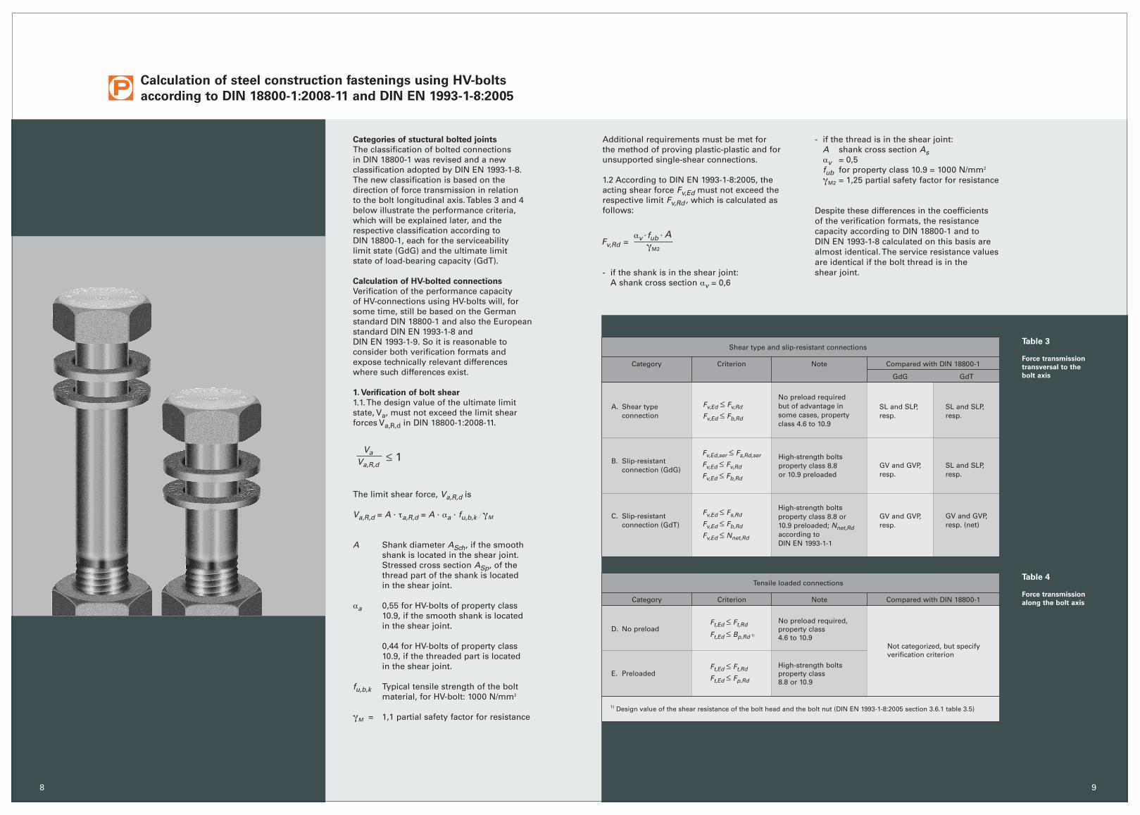
Tensile loaded connections
Category Criterion Note
D. No preloadFt,Ed ≤ Ft,Rd
Ft,Ed ≤ Bp,Rd 1)
No preload required,property class 4.6 to 10.9
Not categorized, but specifyverification criterion
E. PreloadedHigh-strength boltsproperty class8.8 or 10.9
Ft,Ed ≤ Ft,Rd
Ft,Ed ≤ Fp,Rd
Shear type and slip-resistant connections
Category Criterion Note
A. Shear typeconnection
Fv,Ed ≤ Fv,Rd
Fv,Ed ≤ Fb,Rd
No preload required but of advantage insome cases, propertyclass 4.6 to 10.9
SL and SLP,resp.
SL and SLP,resp.
B. Slip-resistantconnection (GdG)
High-strength boltsproperty class 8.8or 10.9 preloaded
GV and GVP,resp.
SL and SLP,resp.
C. Slip-resistantconnection (GdT)
Fv,Ed ≤ Fs,Rd
Fv,Ed ≤ Fb,Rd
Fv,Ed ≤ Nnet,Rd
High-strength boltsproperty class 8.8 or 10.9 preloaded; Nnet,Rdaccording to DIN EN 1993-1-1
GV and GVP,resp.
GV and GVP,resp. (net)
Compared with DIN 18800-1
GdG GdT
Fv,Ed,ser ≤ Fs,Rd,ser
Fv,Ed ≤ Fv,Rd
Fv,Ed ≤ Fb,Rd
Table 3
Force transmission
transversal to the
bolt axis
Table 4
Force transmission
along the bolt axis
8
Calculation of steel construction fastenings using HV-bolts
according to DIN 18800-1:2008-11 and DIN EN 1993-1-8:2005
Aav. fub
.
gM2
1) Design value of the shear resistance of the bolt head and the bolt nut (DIN EN 1993-1-8:2005 section 3.6.1 table 3.5)
Compared with DIN 18800-1
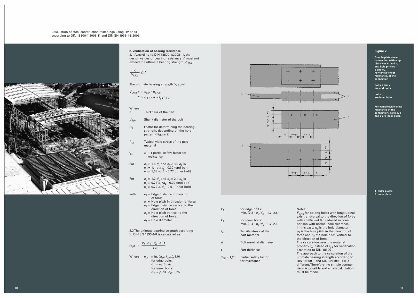
2. Verification of bearing resistance
2.1 According to DIN 18800-1:2008-11, thedesign values of bearing resistance Vl must notexceed the ultimate bearing strength Vl,R,d .
The ultimate bearing strength VI,R,d is
VI,R,d = t . dSch. sI,R,d
= t . dSch. a I
. fy,k gM
Where t Thickness of the part
dSch Shank diameter of the bolt
a l Factor for determining the bearing strength, depending on the hole pattern (Figure 2)
fy,k Typical yield stress of the part material
gM = 1,1 partial safety factor for resistance
For e2 ≥ 1,5 dL and e3 ≥ 3,0 dL isa I = 1,1 e1 /dL - 0,30 (end bolt)a I = 1,08 e /dL - 0,77 (inner bolt)
For e2 = 1,2 dL and e3 = 2,4 dL isaI = 0,73 e1 /dL - 0,20 (end bolt)aI = 0,72 e /dL - 0,51 (inner bolt)
with e1 = Edge distance in direction of force
e = Hole pitch in direction of forcee2 = Edge distance vertical to the
direction of forcee3 = Hole pitch vertical to the
direction of forcedL = Hole diameter
2.2 The ultimate bearing strength according to DIN EN 1993-1-8 is calculated as:
Where ab min. (ad ; fub /fu;1,0)for edge bolts: ad = e1 /3 . d0for inner bolts: ad = p1 /3 . d0 - 0,25
Calculation of steel construction fastenings using HV-bolts according to DIN 18800-1:2008-11 and DIN EN 1993-1-8:2005
VlVl,R,d
≤ 1
k1 for edge bolts: min. (2,8 . e2 /d0 - 1,7; 2,5)
k1 for inner bolts: min. (1,4 . p2 /d0 - 1,7; 2,5)
fu Tensile stress of the part material
d Bolt nominal diameter
t Part thickness
gM2 = 1,25 partial safety factor for resistance
k1. ab
. fu . d . tgM2
Fb,Rd =
Notes: Fb,Rd for oblong holes with longitudinal axis transversal to the direction of force with coefficient 0,6 reduced in com-parison with normal hole clearance.In this case, d0 is the hole diameter; p1 is the hole pitch in the direction of force and p2 the hole pitch vertical to the direction of force.The calculation uses the material property fu instead of fy,k for verificationaccording to DIN 18800-1. The approach to the calculation of the ultimate bearing strength according to DIN 18800-1 and DIN EN 1993-1-8 is different. Therefore, no simple compa-rison is possible and a new calculation must be made.
12
2
1c)b)a)
e:p1e:p1
e:p1 e:p1 e1
e1
e 2e 3
:p
2e 2
e 2e 3
:p
2e 2
10
Figure 2
Double-plate shear
connection with edge
distances e1 and e2
and hole pitches
e and e3.
For tensile shear
resistance, of the
connection
bolts a and c
are end bolts
bolts b
are inner bolts
For compressive shear
resistance of the
connection, bolts a, b
and c are inner bolts.
1 outer plates
2 inner plate
11

Figure 3
Interaction between
tension and shear:
DIN 18800-1:2008-11
DIN EN 1993-1-8:2005
Ft,Ed
Ft,Rd
(tension)
Source: Acquired from Univ.-Prof. Dr. Ing. Ungermann and Dipl.-Ing. Schmidt, Dortmund University
1,0
0,8
0,6
0,4
0,2
0,2 0,4 0,6 0,8 1,00 2860,286
(shear)
DIN EN 1993-1-8
DIN 18800
13
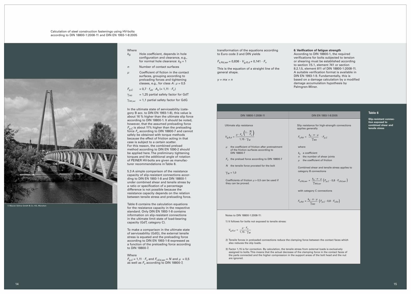
5.2 According to DIN EN 1993-1-8, verificationof slip-resistant HV-connection can be sub-mitted by calculating the slip resistance bothat serviceability limit state (GdG) and ultimate limit state of load-bearing capacity(GdT). Slip resistance Fs,Rd is calculated as:
5. Verification of slip-resistant connections:
(GV und GVP)
5.1 According to DIN 18800-1, the stressesVg decisive for serviceability the followinglimit slip loadsVg,R,d .
The limit slip load Vg,R,d is
Vg,R,d = µ . Fv / (1,15 . gM ), if no externaltensile force acts on the HV-bolt,Vg,R,d = µ . Fv (1-N / Fv) / (1,15 . gM ), if anexternal tensile force acts on the HV-bolt.
Whereµ the coefficient of friction after
pretreatment of the friction surfaces according to DIN 18800-7
Fv the preload force according to DIN 18800-7
N the tensile force prorated for the boltgM = 1,0
In addition to this, verification of struc-tural safety must be provided for GV andGVP connections as for SL and SLPconnections.
Vg
Vg,R,d≤ 1
ks. n . µgM3
Fs,Rd = . Fp,C
DIN EN 1993-1-8:2005
ASp Tension cross section
fu,b,k for property class 10.9 = 1000 N/mm2
1,25 = Coefficient for higher safety against tensile strength
gM = 1,1
ASp . fu,b,k
1,25 .gM
NR,d =
AS Tension cross section
fub for property class 10.9 = 1000 N/mm2
k2 = 0,9
gM2 = 1,25
k2. fub
. AS
gM2
Ft,Rd =
DIN 18800-1:2008-11Table 5
Calculation of ultimate
tensile force to prove
the tensile load of
HV-bolts
12
3. Verification of the tensile stress of HV-bolts
by calculating the ultimate tensile force
based on very similar approaches (Table 5).
For HV-bolts, the following equation applies:
so that the resistance capacity according tothe old and the new norm can be assumed to be the same.
4. Combination of tension and shear
According to DIN 18800-1, the verification ofthe following interaction must be provided:
WhereN, Va Design values of tension and ultimate
limit statesNR,d see 3Va,R,d see 1.1
No verification of interaction is required if N / NR,d or Va / Va,R,d is smaller than 0,25.
According to DIN EN 1993-1-8, the interactionterm is obtained form the analysis of experi-mental results as
Thus, interactions between both loads arerated differently (Figure 3).
Ft ,Rd
NR,d
= 0,99
NNR,d( ) Va
Va,R,d( )2 2
+ ≤ 1
Fv,Ed
Fv,Rd
Ft,Ed
1,4 Ft,Rd+ ≤ 1,0
Calculation of steel construction fastenings using HV-bolts according to DIN 18800-1:2008-11 and DIN EN 1993-1-8:2005
N
NR,d;
Fv,Ed
Fv,Rd
Va
Va,R,d;
14 15
Calculation of steel construction fastenings using HV-bolts according to DIN 18800-1:2008-11 and DIN EN 1993-1-8:2005
DIN EN 1993-1-8:2005
Ultimate slip resistance
where
ks a coefficientn the number of shear jointsµ the coefficient of friction
Combined shear and tensile stress applies tocategory B connections
with category C connections
Fs,Rd =
DIN 18800-1:2008-11Table 6
Slip-resistant connec-
tion exposed to
combined shear and
tensile stress
© Maurer Söhne GmbH & Co. KG, München
µ the coefficient of friction after pretreatment of the friction surfaces according to DIN 18800-7
Fv the preload force according to DIN 18800-7
N the tensile force prorated for the bolt
gM = 1,0
Coefficients of friction µ > 0,5 can be used ifthey can be proved.
. Fp,C
WherekS Hole coefficient, depends in hole
configuration and clearance, e.g., for normal hole clearance: kS = 1
n Number of contact surfaces
µ Coefficient of fiction in the contact surfaces, grouping according to preloading forces and tightening classes, e.g., for class A : µ = 0,5
Fp,C = 0,7 . fub . As (= 1,11 . Fv)
gM3 = 1,25 partial safety factor for GdT
gM3,ser = 1,1 partial safety factor for GdG
In the ultimate state of serviceability (cate-gory B acc. to DIN EN 1993-1-8), this value isabout 16 % higher than the ultimate slip force according to DIN 18800-1. It should be noted,however, that the assumed preloading forceFp,C is about 11% higher than the preloadingforce Fv according to DIN 18800-7 and cannotsafely be obtained with torque methodsbecause the effect of friction acting in thatcase is subject to a certain scatter.For this reason, the combined preloadmethod according to DIN EN 1090-2 shouldbe applied here. The preliminary tighteningtorques and the additional angle of rotationof PEINER HV-bolts are given as manufac-turer recommendations in Table 8.
5.3 A simple comparison of the resistancecapacity of slip-resistant connections accor-ding to DIN EN 1993-1-8 and DIN 18800-1under combined shear and tensile stress by a ratio or specification of a percentage difference is not possible because the resistance capacity depends on the relationbetween tensile stress and preloading force.
Table 6 contains the calculation equations for the resistance capacity in the respectivestandard. Only DIN EN 1993-1-8 containsinformation on slip-resistant connections in the ultimate limit state of load-bearing capacity (GdT, category C).
To make a comparison in the ultimate state of serviceability (GdG), the external tensilestress is equated and the preloading forceaccording to DIN EN 1993-1-8 expressed as a function of the preloading force accordingto DIN 18800-7.
WhereFp,C = 1,11 . Fv and Ft,Ed,ser = N and µ = 0,5 as well as Fv according to DIN 18800-7,
Notes to DIN 18800-1:2008-11:
1) It follows for bolts not exposed to tensile stress:
Vg,R,d = µ . Fv
1,15 . gM
2) Tensile forces in preloaded connections reduce the clamping force between the contact faces which also reduces the slip loads.
3) Factor 1,15 is for correction. By calculation, the tensile stress from external loads is exclusively assigned to bolts. This means that the actual decrease of the clamping force in the contact faces of the parts connected and the higher compression in the support areas of the bolt head and the nut are ignored.
Slip resistance for high-strength connectionsapplies generally
( )
)(
)(
transformation of the equations according to Euro code 3 and DIN yields
Fs,Rd,ser = 0,836 . Vg,R,d + 0,141 . Fv
This is the equation of a straight line of thegeneral shape.
y = mx + n
6. Verification of fatigue strength
According to DIN 18800-1, the required verifications for bolts subjected to tension or shearing must be established according to section 7.5.1, element 741 or section8.2.1.5, element 811 of DIN 18800-1:2008-11. A suitable verification format is available in DIN EN 1993-1-9. Fundamentally, this is based on a damage calculation by a modified damage accumulation hypothesis byPalmgren-Miner.
Vg,R,d = µ . Fv
1,15 . gM
NFv
1 -
ks . n . µ
gM3,ser
Fs,Rd,ser = Fp,C - 0,8 . Ft,Ed,ser
ks . n . µ
gM3
Fs,Rd = Fp,C - 0,8 . Ft,Ed
ks . n . µ
gM3
Preloading
PEINER HV-bolt connections
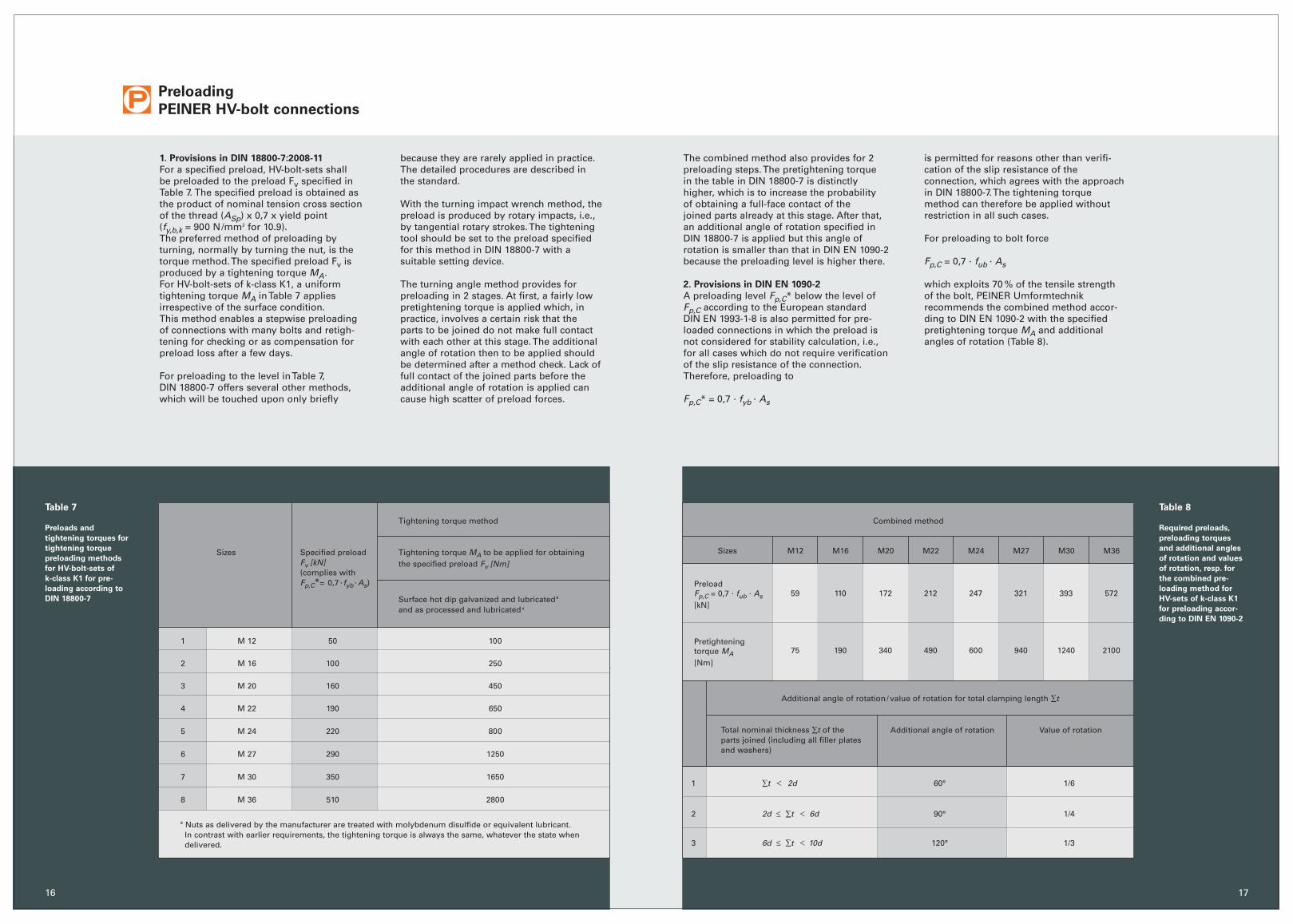
1. Provisions in DIN 18800-7:2008-11
For a specified preload, HV-bolt-sets shall be preloaded to the preload Fv specified in Table 7. The specified preload is obtained asthe product of nominal tension cross sectionof the thread (ASp) x 0,7 x yield point (fy,b,k = 900 N/mm2 for 10.9).The preferred method of preloading by turning, normally by turning the nut, is the torque method. The specified preload Fv isproduced by a tightening torque MA.For HV-bolt-sets of k-class K1, a uniform tightening torque MA in Table 7 applies irrespective of the surface condition. This method enables a stepwise preloadingof connections with many bolts and retigh-tening for checking or as compensation forpreload loss after a few days.
For preloading to the level in Table 7, DIN 18800-7 offers several other methods,which will be touched upon only briefly
Total nominal thickness ∑t of the parts joined (including all filler plates and washers)
Additional angle of rotation
Additional angle of rotation/ value of rotation for total clamping length ∑t
1 ∑t Ø 2d 60° 1/6
2 2d ≤ ∑t Ø 6d 90° 1/4
3 6d ≤ ∑t Ø 10d 120° 1/3
17
because they are rarely applied in practice.The detailed procedures are described in the standard.
With the turning impact wrench method, thepreload is produced by rotary impacts, i.e.,by tangential rotary strokes. The tighteningtool should be set to the preload specified for this method in DIN 18800-7 with a suitable setting device.
The turning angle method provides for preloading in 2 stages. At first, a fairly low pretightening torque is applied which, inpractice, involves a certain risk that the parts to be joined do not make full contactwith each other at this stage. The additionalangle of rotation then to be applied shouldbe determined after a method check. Lack of full contact of the joined parts before theadditional angle of rotation is applied cancause high scatter of preload forces.
Combined method
Sizes M12 M16 M20 M22 M24 M27 M30 M36
PreloadFp,C = 0,7 . fub
. As[kN]
Pretightening torque MA[Nm]
59 110 172 212 247 321 393 572
75 190 340 490 600 940 1240 2100
The combined method also provides for 2preloading steps. The pretightening torque in the table in DIN 18800-7 is distinctly higher, which is to increase the probability of obtaining a full-face contact of the joined parts already at this stage. After that,an additional angle of rotation specified inDIN 18800-7 is applied but this angle of rotation is smaller than that in DIN EN 1090-2because the preloading level is higher there.
2. Provisions in DIN EN 1090-2
A preloading level Fp,C* below the level ofFp,C according to the European standard DIN EN 1993-1-8 is also permitted for pre-loaded connections in which the preload isnot considered for stability calculation, i.e.,for all cases which do not require verification of the slip resistance of the connection.Therefore, preloading to
Fp,C* = 0,7 . fyb . As
is permitted for reasons other than verifi-cation of the slip resistance of the connection, which agrees with the approachin DIN 18800-7. The tightening torque method can therefore be applied withoutrestriction in all such cases.
For preloading to bolt force
Fp,C = 0,7 . fub . As
which exploits 70 % of the tensile strength of the bolt, PEINER Umformtechnik recommends the combined method accor-ding to DIN EN 1090-2 with the specified pretightening torque MA and additionalangles of rotation (Table 8).
16
Sizes Specified preloadFv [kN](complies withFp,C*= 0,7 . fyb
. As)
Tightening torque MA to be applied for obtainingthe specified preload Fv [Nm]
Surface hot dip galvanized and lubricateda
and as processed and lubricated a
1 M 12 50 100
2 M 16 100 250
3 M 20 160 450
4 M 22 190 650
5 M 24 220 800
6 M 27 290 1250
7 M 30 350 1650
8 M 36 510 2800
Table 7
Preloads and
tightening torques for
tightening torque
preloading methods
for HV-bolt-sets of
k-class K1 for pre-
loading according to
DIN 18800-7
a Nuts as delivered by the manufacturer are treated with molybdenum disulfide or equivalent lubricant. In contrast with earlier requirements, the tightening torque is always the same, whatever the state when delivered.
Tightening torque method
Table 8
Required preloads,
preloading torques
and additional angles
of rotation and values
of rotation, resp. for
the combined pre-
loading method for
HV-sets of k-class K1
for preloading accor-
ding to DIN EN 1090-2
Value of rotation
Notes specifically for bolt connections of
specified preload:
• When preload is applied by turning the bolt head, the specified preload should be obtained, for example, by checking the method for the preloading behavior by suitable lubrication of the bolt head-end washer or the contact area of the bolt head.
• For coatings of contact faces of SLV and SLVP connections, observe DIN 18800-7:2008-11, table 4. Preload losses can be compensated by retightening the bolted connection.
• If a specified preload set is opened, it should be removed and a new set installed. If for opened sets preloaded by the torque or impact wrench method it is shown that no permanent damage was done to the bolt during first preloading, that bolt can be preloaded with a new nut and a new washer from the same manufacturer.Our recommendation is: In case of opening an installed bolt tightened up to the full pre-load one usually does not know and cannot identify which tightening procedure has been applied before and whether the bolt sat perfectly in place or even has already got some plastic deformation. Therefore it isadvisable to completely replace it anyway.
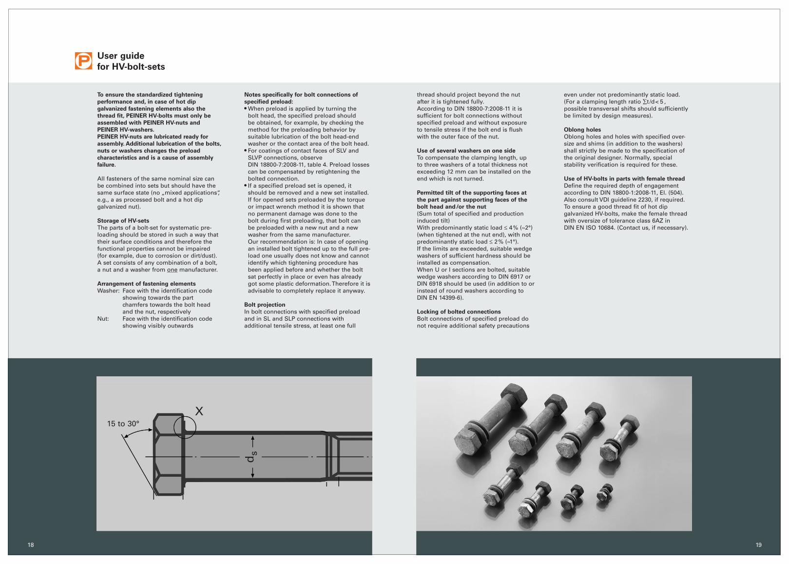
Bolt projection
In bolt connections with specified preloadand in SL and SLP connections with additional tensile stress, at least one full
User guide
for HV-bolt-sets
To ensure the standardized tightening
performance and, in case of hot dip
galvanized fastening elements also the
thread fit, PEINER HV-bolts must only be
assembled with PEINER HV-nuts and
PEINER HV-washers.
PEINER HV-nuts are lubricated ready for
assembly. Additional lubrication of the bolts,
nuts or washers changes the preload
characteristics and is a cause of assembly
failure.
All fasteners of the same nominal size can be combined into sets but should have thesame surface state (no „mixed applications“,e.g., a as processed bolt and a hot dip galvanized nut).
Storage of HV-sets
The parts of a bolt-set for systematic pre-loading should be stored in such a way thattheir surface conditions and therefore thefunctional properties cannot be impaired (for example, due to corrosion or dirt/dust).A set consists of any combination of a bolt, a nut and a washer from one manufacturer.
Arrangement of fastening elements
Washer: Face with the identification code showing towards the part chamfers towards the bolt headand the nut, respectively
Nut: Face with the identification code showing visibly outwards
thread should project beyond the nut after it is tightened fully.According to DIN 18800-7:2008-11 it is sufficient for bolt connections without specified preload and without exposure to tensile stress if the bolt end is flush with the outer face of the nut.
Use of several washers on one side
To compensate the clamping length, up to three washers of a total thickness not exceeding 12 mm can be installed on the end which is not turned.
Permitted tilt of the supporting faces at
the part against supporting faces of the
bolt head and/or the nut
(Sum total of specified and production induced tilt)With predominantly static load ≤ 4% (≈2°)(when tightened at the nut end), with not predominantly static load ≤ 2% (≈1°).If the limits are exceeded, suitable wedgewashers of sufficient hardness should beinstalled as compensation.When U or I sections are bolted, suitablewedge washers according to DIN 6917 or DIN 6918 should be used (in addition to orinstead of round washers according to DIN EN 14399-6).
Locking of bolted connections
Bolt connections of specified preload do not require additional safety precautions
even under not predominantly static load. (For a clamping length ratio ∑t /d< 5 , possible transversal shifts should sufficientlybe limited by design measures).
Oblong holes
Oblong holes and holes with specified over-size and shims (in addition to the washers)shall strictly be made to the specification ofthe original designer. Normally, special stability verification is required for these.
Use of HV-bolts in parts with female thread
Define the required depth of engagementaccording to DIN 18800-1:2008-11, El. (504).Also consult VDI guideline 2230, if required.To ensure a good thread fit of hot dip galvanized HV-bolts, make the female threadwith oversize of tolerance class 6AZ in DIN EN ISO 10684. (Contact us, if necessary).
1918
X
ds
15 to 30°


![BauStatik S785 Beulnachweis, DIN 18800 (11/90) · DIN 18800-2 [2], DIN 4114 [3] • Freie Eingabe der Beulwerte möglich • Ermittlung der Abminderungsfaktoren ...](https://static.cupdf.com/doc/110x72/5afffbe57f8b9a89598be61c/baustatik-s785-beulnachweis-din-18800-1190-18800-2-2-din-4114-3-freie.jpg)


![!,y]e - itc.co.iritc.co.ir/wp-content/uploads/2015/01/EN-14399-10.pdf · DIN EN 14399-10 Hochfeste ... EN 10045-1, Metallische Werkstoffe — Kerbschlagbiegeversuch nach Charpy —](https://static.cupdf.com/doc/110x72/5a7503ab7f8b9aea3e8c2bfc/ye-itccoiritccoirwp-contentuploads201501en-14399-10pdf-din-en.jpg)


