


SCADA
Supervisory control And Data
Acquisition
SARATH S NAIRAssistant Professor, Amrita University,India
Sarath S Nair, www.technologyfuturae.com
INDUSTRIAL AUTOMATION
Industrial Power GroupDept. Of Electrical Engineering, NIT Calicut
Sarath S Nair, www.technologyfuturae.com
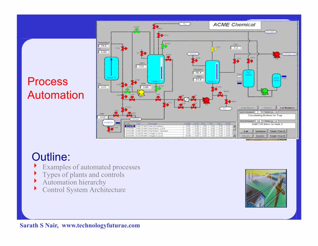
Process
Automation
Outline:4 Examples of automated processes4 Types of plants and controls4 Automation hierarchy4 Control System Architecture
Sarath S Nair, www.technologyfuturae.com
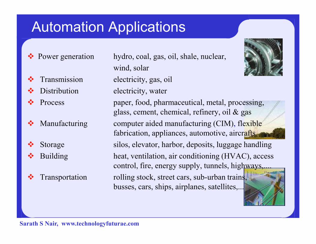
Automation Applications
� Power generation hydro, coal, gas, oil, shale, nuclear,
wind, solar
� Transmission electricity, gas, oil
� Distribution electricity, water
� Process paper, food, pharmaceutical, metal, processing,
glass, cement, chemical, refinery, oil & gas
� Manufacturing computer aided manufacturing (CIM), flexible � Manufacturing computer aided manufacturing (CIM), flexible
fabrication, appliances, automotive, aircrafts
� Storage silos, elevator, harbor, deposits, luggage handling
� Building heat, ventilation, air conditioning (HVAC), access
control, fire, energy supply, tunnels, highways,....
� Transportation rolling stock, street cars, sub-urban trains,
busses, cars, ships, airplanes, satellites,...
Sarath S Nair, www.technologyfuturae.com
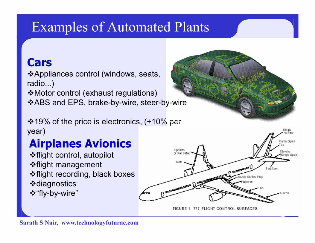
Examples of Automated Plants
Cars�Appliances control (windows, seats,
radio,..)
�Motor control (exhaust regulations)
�ABS and EPS, brake-by-wire, steer-by-wire
�19% of the price is electronics, (+10% per �19% of the price is electronics, (+10% per
year)
Airplanes Avionics�flight control, autopilot
�flight management
�flight recording, black boxes
�diagnostics
�“fly-by-wire”
Sarath S Nair, www.technologyfuturae.com

Examples of Automated Plants
Flexible Automation, Manufacturing
Numerous conveyors,
robots, CNC
machines, paint
shops, logistics.
Sarath S Nair, www.technologyfuturae.com

Examples of Automated Plants:
Oil, Gas and Petrochemicals
Upstream:from the earth to the refinery
(High pressure, saltwater, inaccessibilityexplosive environment with gas) Downstream:
Distribution:
(environmental protection)
with gas) Downstream:
(extreme explosiveenvironment)
Sarath S Nair, www.technologyfuturae.com

Examples of Automated Plants:
Power plants
4 Raw materials
supply
4 Primary process
(steam, wind)
4 Personal, plant
and
neighbourhood
safetysafety
4 Environmental
impact
4 Generation
process
(voltage/frequency
)
4 Energy
distribution
(substation)
Sarath S Nair, www.technologyfuturae.com

Examples of Automated Plants:
Waste treatment, incinerators
4 Raw material supply
4 Burning process
4 Smoke cleaning
4 Environmental control
44 Co-generation process (steam, heat)
4 Ash analysis
4 Ash disposal
Sarath S Nair, www.technologyfuturae.com
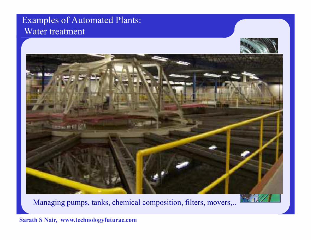
Examples of Automated Plants:
Water treatment
Managing pumps, tanks, chemical composition, filters, movers,..
Sarath S Nair, www.technologyfuturae.com

Automation Systems Manufacturers
Company Location Major mergers
ABB CH-SE Brown Boveri, ASEA, CE, Alfa-Laval, Elsag-
Bailey
Siemens DE Plessey, Landis & Gyr, Stäfa, Cerberus,..
Ansaldo IT
Emerson US Fisher Rosemount
General Electric US
Honeywell US
Rockwell
Automation
US Allen Bradley, Rockwell,..
Alstom FR Alsthom, GEC, CEGELEC, ABB Power,..
Schneider Electric FR Télémécanique, Square-D, ...
Invensys UK Foxboro, Siebe, BTR, Triconex,…
Hitachi JP
Yokogawa JP
Technical Necessity of Automation
� Processing of the information flow
� Enforcement of safety and availability
� Reduction of personal costs
Sarath S Nair, www.technologyfuturae.com

Expectations of Automation
� Process Optimisation
– Energy, material and time savings
– Quality improvement, reduction of waste, pollution control
– compliance with laws, product tracking
– Increase availability, safety
– Fast response to market
– Connection to management and accounting � Acquisition of large number of “Process Variables”, data mining� Personal costs reduction
– Simplify interface– Simplify interface
– Assist decision
– Require data processing, displays, data base, expert systems� Human-Machine Interface (MMC = Man-Machine Communication)� Asset Optimisation
– Automation of engineering, commissioning and maintenance
– Software configuration, back-up and versioning
– Maintenance support� Engineering Tools
Sarath S Nair, www.technologyfuturae.com

Data Quantity in Different Plants
4 Power Plant (25 years ago)
– 100 measurement and action variables (called "points")
– Analog controllers, analog instruments
– one central "process controller" for data monitoring and protocol.
4 Thermal power plant (today)
– 10000 points, comprising:• 8000 binary and analog measurement points and• 2000 actuation point
– 1000 micro-controllers and logic controllers– 1000 micro-controllers and logic controllers
4 Nuclear Power Plant
– three times more points than in conventional power plants
4 Electricity distribution network
– 100’000 – 10’000’000 points
4 Data reduction and processing is necessary to operate plants
Sarath S Nair, www.technologyfuturae.com
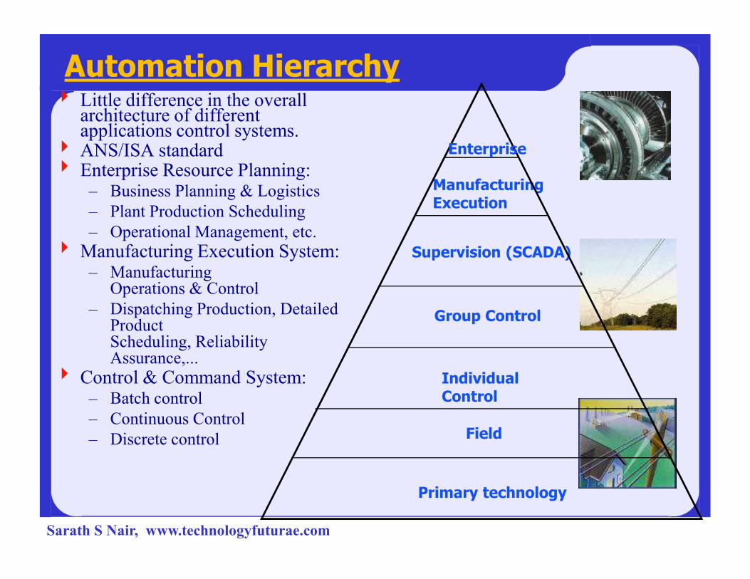
4 Little difference in the overall architecture of different applications control systems.
4 ANS/ISA standard4 Enterprise Resource Planning:
– Business Planning & Logistics
– Plant Production Scheduling
– Operational Management, etc.
4 Manufacturing Execution System:– Manufacturing
Operations & Control
Manufacturing Execution
Supervision (SCADA)
Enterprise
Automation Hierarchy
Operations & Control
– Dispatching Production, Detailed ProductScheduling, Reliability Assurance,...
4 Control & Command System:– Batch control
– Continuous Control
– Discrete control
Group Control
Individual Control
Field
Primary technology
Sarath S Nair, www.technologyfuturae.com

Example: Siemens WinCC
Sarath S Nair, www.technologyfuturae.com

Large control system hierarchy
enterprise
Group Control
Supervisory
Workflow, Resources,
Interactions SCADA =Supervisory ControlAnd Data Acquisition
administrationPlanning, Statistics, Finances
supervision
2
3
4
Group Control
Unit Control
Field
Sensors & Actuators A V
Primary technology
T
1
0
Sarath S Nair, www.technologyfuturae.com

Large control system hierarchy
4 Administration:
– Production goals, planning
4 Enterprise:
– Manages resources, workflow, coordinates activities of different sites
quality supervision, maintenance, distribution and planning
4 Supervision:
– Supervision of the site, optimization, on-line operations, Control room, – Supervision of the site, optimization, on-line operations, Control room,
Process Data Base, logging (open loop)
4 Group (Area):
– Control of a well-defined part of the plant (closed loop, except for
intervention of an operator)• Coordinates individual subgroups, Adjusting set-points and parameters• Commands several units as a whole
Sarath S Nair, www.technologyfuturae.com
Large control system hierarchy
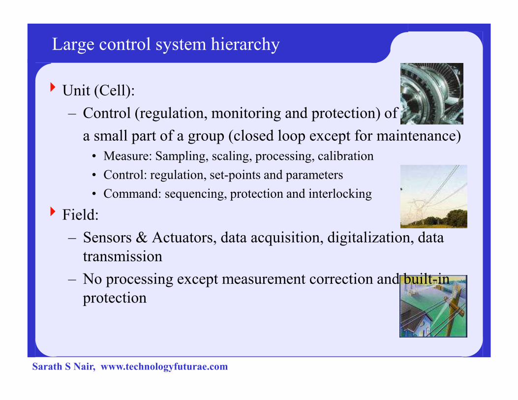
4Unit (Cell):
– Control (regulation, monitoring and protection) of
a small part of a group (closed loop except for maintenance)
• Measure: Sampling, scaling, processing, calibration
• Control: regulation, set-points and parameters
• Command: sequencing, protection and interlocking• Command: sequencing, protection and interlocking
4Field:
– Sensors & Actuators, data acquisition, digitalization, data
transmission
– No processing except measurement correction and built-in
protection
Sarath S Nair, www.technologyfuturae.com

Field level
4Field level is in
direct
interaction with
the plant's
hardwarehardware
Sarath S Nair, www.technologyfuturae.com
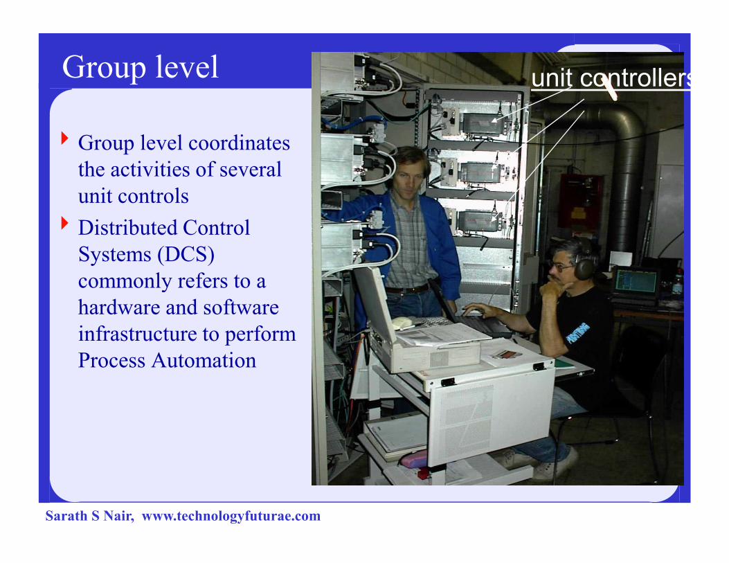
Group level unit controllers
4Group level coordinates
the activities of several
unit controls
4Distributed Control
Systems (DCS)
commonly refers to a commonly refers to a
hardware and software
infrastructure to perform
Process Automation
Sarath S Nair, www.technologyfuturae.com

Local human interface at group level
Sometimes, the group level has its own man-machine interface for local operation control (here: cement packaging)
Maintenance console / emergency panel
Sarath S Nair, www.technologyfuturae.com

Supervisory level: Man-machine interface
4Control room (mimic wall) 1970s...
4All instruments were directly wired to the control room
Sarath S Nair, www.technologyfuturae.com
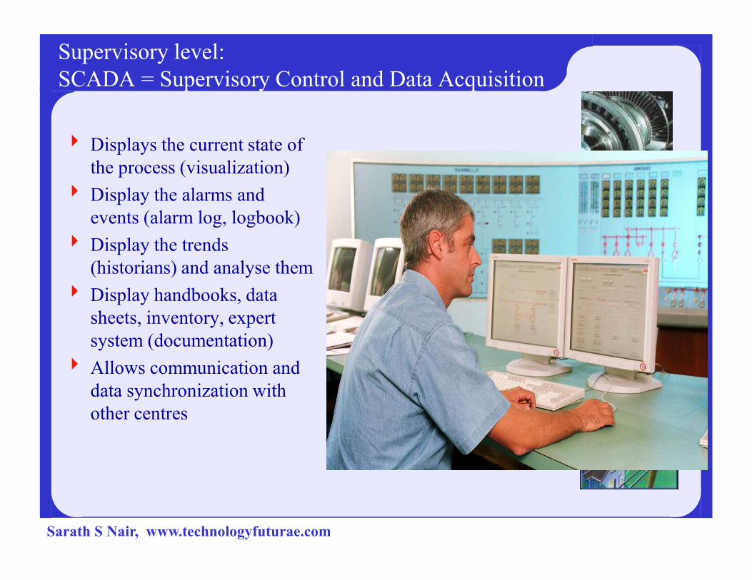
Supervisory level:
SCADA = Supervisory Control and Data Acquisition
4 Displays the current state of
the process (visualization)
4 Display the alarms and
events (alarm log, logbook)
4 Display the trends
(historians) and analyse them
4 Display handbooks, data 4 Display handbooks, data
sheets, inventory, expert
system (documentation)
4 Allows communication and
data synchronization with
other centres
Sarath S Nair, www.technologyfuturae.com
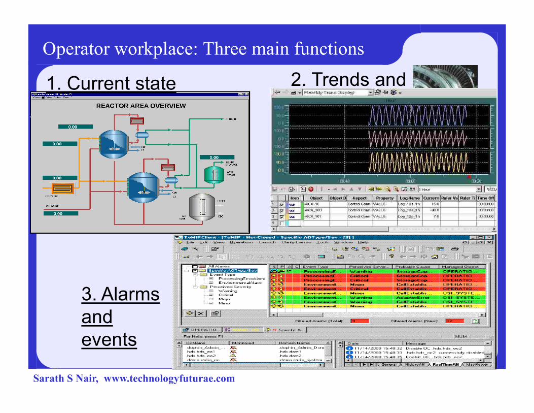
Operator workplace: Three main functions
1. Current state 2. Trends and
history
3. Alarms
and
events
Sarath S Nair, www.technologyfuturae.com
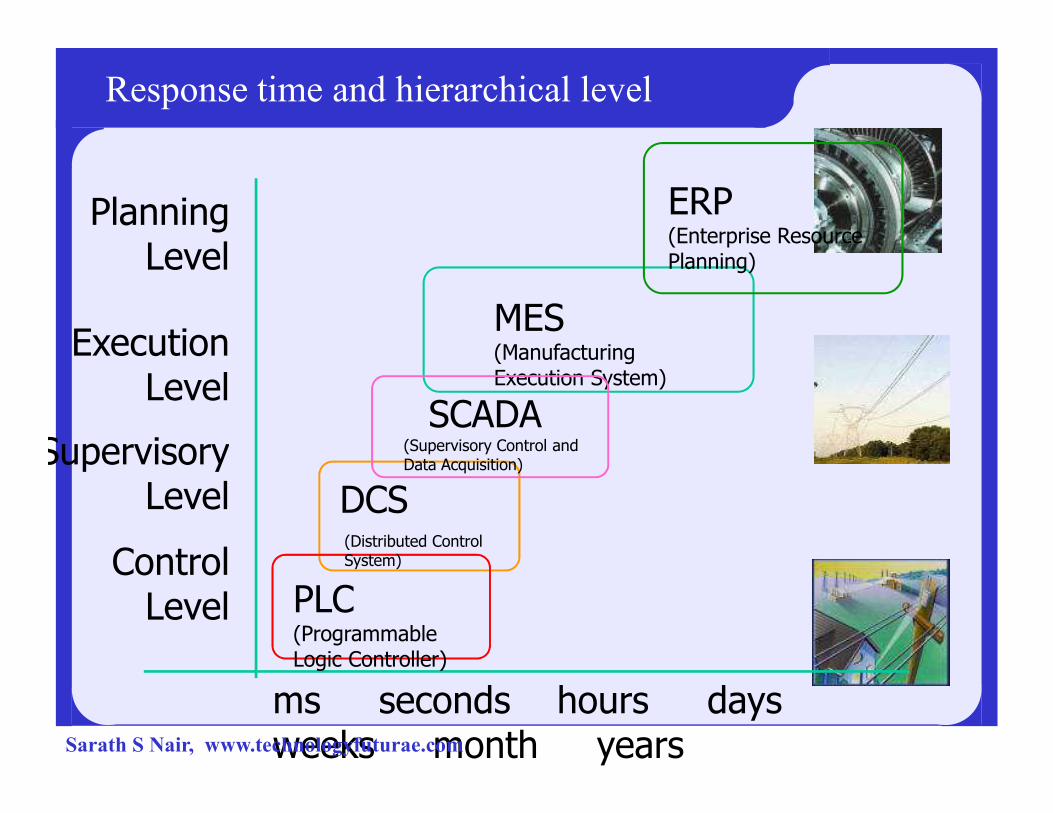
Response time and hierarchical level
PlanningLevel
ExecutionLevel
ERP(Enterprise Resource Planning)
MES(Manufacturing Execution System)
SCADALevel
ControlLevel
SupervisoryLevel
ms seconds hours days weeks month years
DCS
PLC(Programmable Logic Controller)
(Distributed Control System)
(Supervisory Control and Data Acquisition)
SCADA
Sarath S Nair, www.technologyfuturae.com

Complexity and Reaction Speed in Hierarchical levels
MES
Supervision
ERP
days
months
minutes
Group Control
Individual Control
Field
SiteComplexity Reaction Speed
seconds
0.1s
0.01s
Sarath S Nair, www.technologyfuturae.com
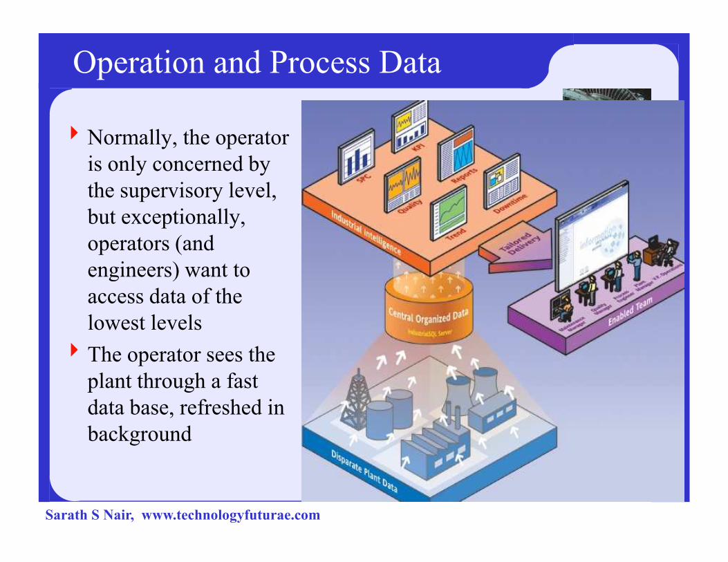
Operation and Process Data
4Normally, the operator
is only concerned by
the supervisory level,
but exceptionally,
operators (and
engineers) want to engineers) want to
access data of the
lowest levels
4The operator sees the
plant through a fast
data base, refreshed in
background
Sarath S Nair, www.technologyfuturae.com
Brief history of SCADA
� The first ‘SCADA’ systems utilized data acquisition by means of panels of meters, lights and strip chart recorders.
�The operator manually operates various control �The operator manually operates various control knobs and exercise supervisory control.
�These devices are still used to do supervisory control and data acquisition on plants, factories and power generating facilities.
Sarath S Nair, www.technologyfuturae.com
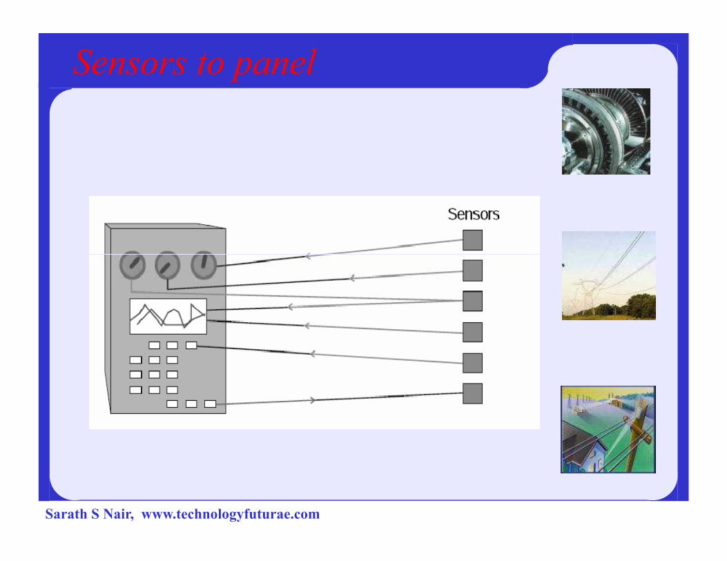
Sensors to panel
Sarath S Nair, www.technologyfuturae.com
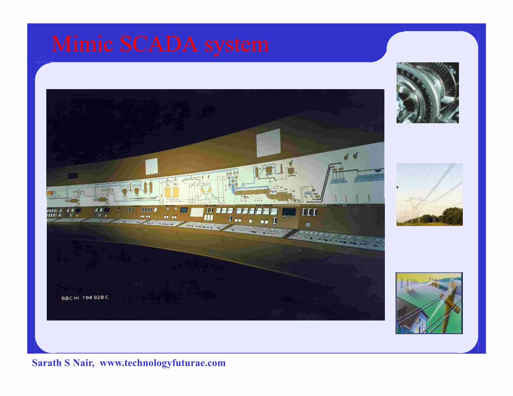
Mimic SCADA system
Sarath S Nair, www.technologyfuturae.com
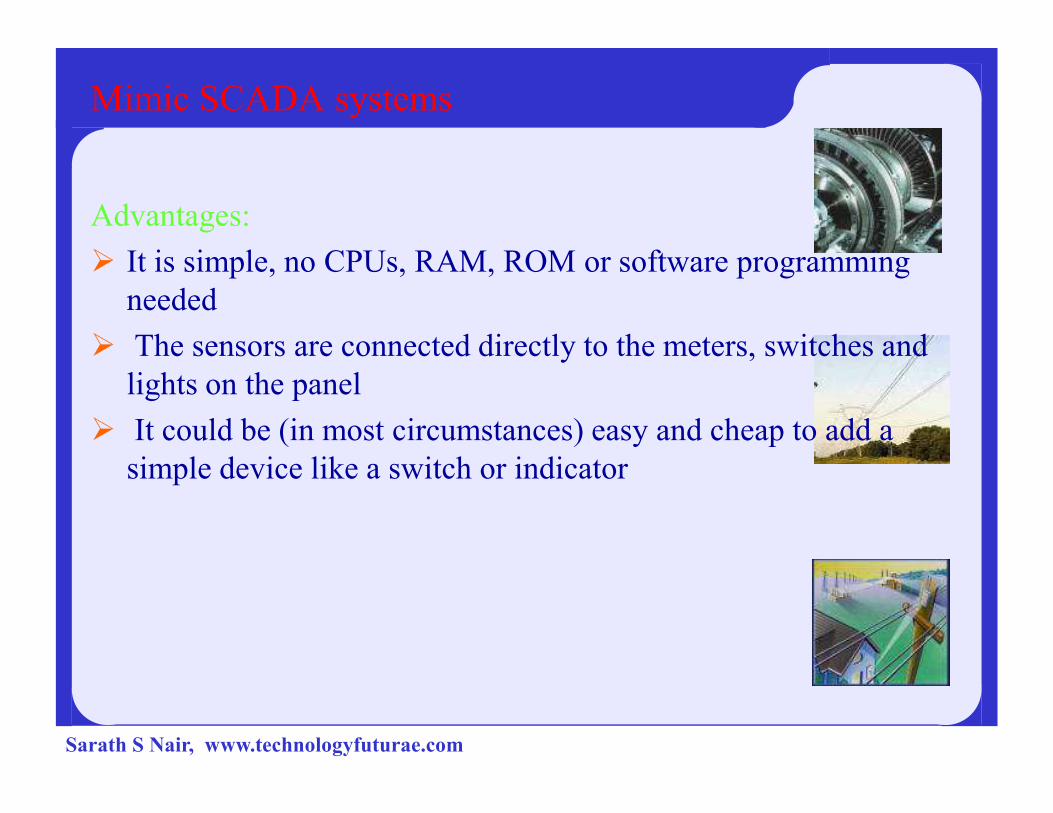
Mimic SCADA systems
Advantages:
� It is simple, no CPUs, RAM, ROM or software programming
needed
� The sensors are connected directly to the meters, switches and
lights on the panel
� It could be (in most circumstances) easy and cheap to add a
simple device like a switch or indicator
Sarath S Nair, www.technologyfuturae.com

Mimic SCADA systems
Disadvantages:
�The amount of wire becomes unmanageable
after the installation of hundreds of sensors
�The quantity and type of data are minimal and rudimentary
� Installation of additional sensors becomes progressively � Installation of additional sensors becomes progressively harder as the system grows
�Re-configuration of the system becomes extremely difficult
� Simulation using real data is not possible
� Storage of data is minimal and difficult to manage
� No off site monitoring of data or alarms
� 24 Hour around monitoring is required.
Sarath S Nair, www.technologyfuturae.com
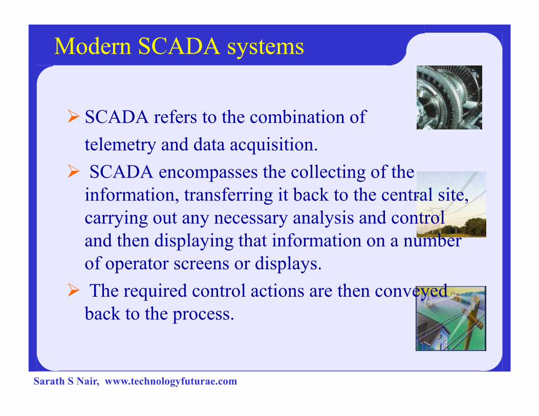
Modern SCADA systems
� SCADA refers to the combination of
telemetry and data acquisition.
� SCADA encompasses the collecting of the
information, transferring it back to the central site,
carrying out any necessary analysis and control carrying out any necessary analysis and control
and then displaying that information on a number
of operator screens or displays.
� The required control actions are then conveyed
back to the process.
Sarath S Nair, www.technologyfuturae.com
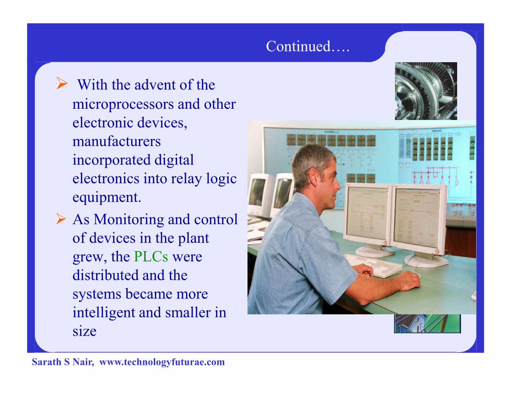
Continued….
� With the advent of the
microprocessors and other
electronic devices,
manufacturers
incorporated digital
electronics into relay logic
equipment.equipment.
� As Monitoring and control
of devices in the plant
grew, the PLCs were
distributed and the
systems became more
intelligent and smaller in
size
Sarath S Nair, www.technologyfuturae.com

SCADA Architecture
Sarath S Nair, www.technologyfuturae.com

EVOLUTION
Of SCADA Architecture
Sarath S Nair, www.technologyfuturae.com

PC to PLC / DCS SCADA system with a field bus
and sensors
Sarath S Nair, www.technologyfuturae.com

PLC / DCS SCADA system
Advantages:
� The computer can record and store a very large amount of data
� The data can be displayed in any way the user requires
� Thousands of sensors over a wide area can be � Thousands of sensors over a wide area can be connected to the system
� The operator can incorporate real data simulations into the system
� Many types of data can be collected from the RTUs
� The data can be viewed from anywhere, not just on site
Sarath S Nair, www.technologyfuturae.com

PLC / DCS SCADA system
Disadvantages:
� The system is more complicated than the
sensor to panel type
�Different operating skills are required,
such as system analysts and programmersuch as system analysts and programmer
�With thousands of sensors there is still a
lot of wire to deal with
� The operator can see only as far as the
PLC
Sarath S Nair, www.technologyfuturae.com
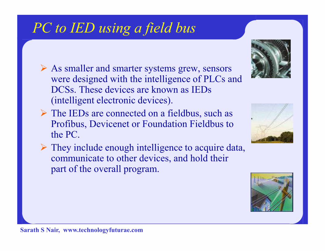
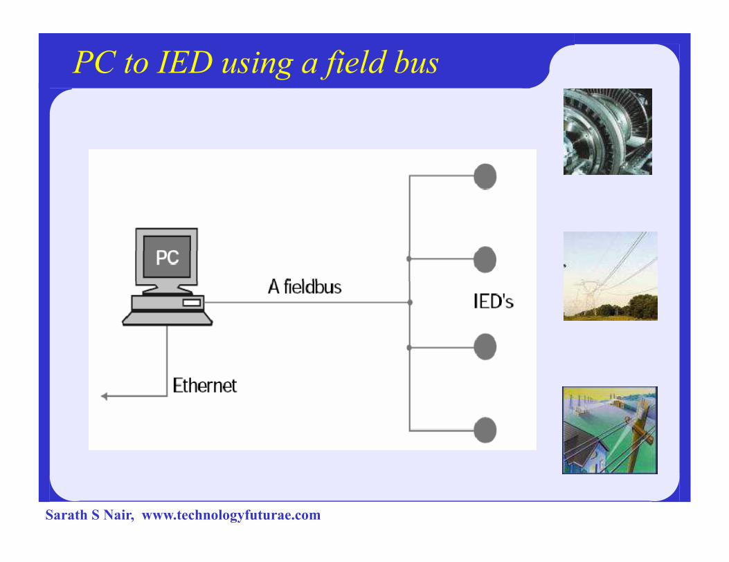
PC to IED using a field bus
� As smaller and smarter systems grew, sensors were designed with the intelligence of PLCs and DCSs. These devices are known as IEDs (intelligent electronic devices).
� The IEDs are connected on a fieldbus, such as Profibus, Devicenet or Foundation Fieldbus to Profibus, Devicenet or Foundation Fieldbus to the PC.
� They include enough intelligence to acquire data, communicate to other devices, and hold their part of the overall program.
Sarath S Nair, www.technologyfuturae.com
Continued….
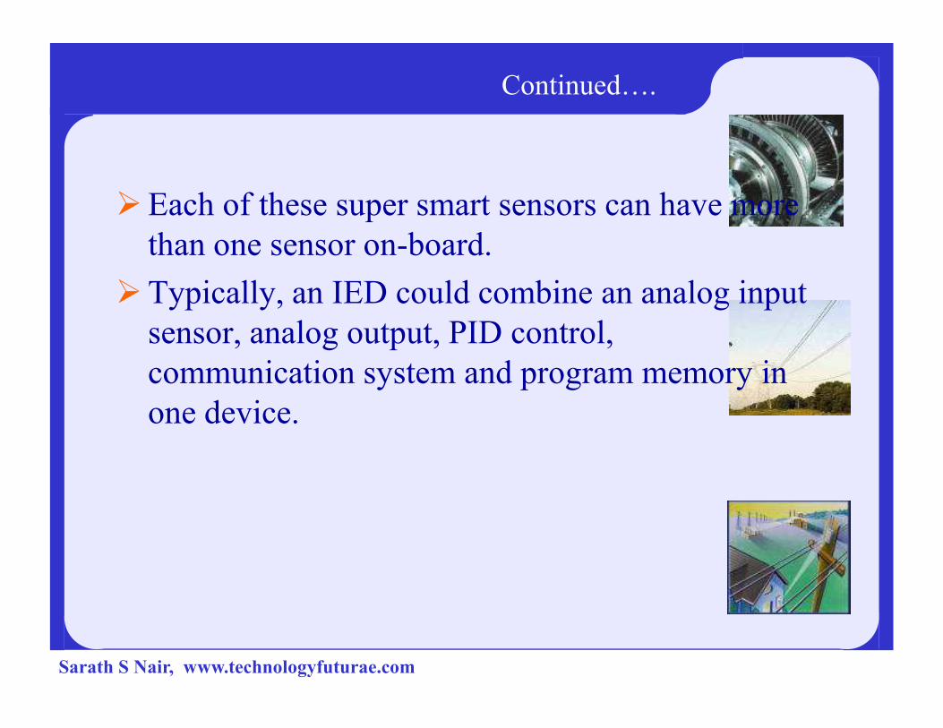
�Each of these super smart sensors can have more
than one sensor on-board.
�Typically, an IED could combine an analog input
sensor, analog output, PID control,
communication system and program memory in communication system and program memory in
one device.
Sarath S Nair, www.technologyfuturae.com
PC to IED using a field bus
Sarath S Nair, www.technologyfuturae.com

PC to IED using a field bus
Advantages:� Minimal wiring is needed
� The operator can see down to the sensor level
� The data received from the device can include information such as serial numbers, model numbers, when it was such as serial numbers, model numbers, when it was installed and by whom
� All devices are plug and play, so installation and replacement is easy
� Smaller devices means less physical space for the data acquisition system
Sarath S Nair, www.technologyfuturae.com
PC to IED using a field bus
Disadvantages:
�More sophisticated system requires better trained
employees
� Sensor prices are higher (but this is offset
somewhat by the lack of PLCs)somewhat by the lack of PLCs)
�The IEDs rely more on the communication system
Sarath S Nair, www.technologyfuturae.com
SCADA hardware
�A SCADA system consists of a number of
remote terminal units (RTUs) collecting field data
and sending that data back to a master station, via
a communication system.
�The master station displays the acquired data and �The master station displays the acquired data and
allows the operator to perform remote control
tasks.
�The RTU provides an interface to the field analog
and digital sensors situated at each remote site.
Sarath S Nair, www.technologyfuturae.com

Diagram of a typical SCADA system
Sarath S Nair, www.technologyfuturae.com

Functions of SCADA System
A SCADA system performs four functions:
1.Data acquisition 2.Networked data communication 3.Data presentation 4.Control
These functions are performed by four kinds of These functions are performed by four kinds of SCADA components .
1.Sensors 2.Remote telemetry units (RTUs )3. SCADA master units
4. communications network
Sarath S Nair, www.technologyfuturae.com
SCADA System Hierarchies
Field level instrumentation and control devices
Marshalling terminals and RTUs
Communications system
The master station(s)
The commercial data processing department computer The commercial data processing department computer
system
Sarath S Nair, www.technologyfuturae.com
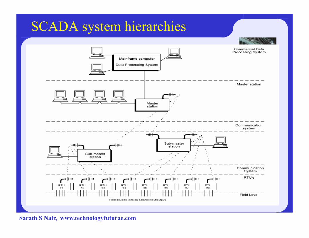
SCADA system hierarchies
Sarath S Nair, www.technologyfuturae.com
� The communications system provides the pathway
for communication between the master station andthe remote sites.
� This communication system can be wire, fiber optic,radio, telephone line, microwave and possibly evensatellite.
� Specific protocols and error detection philosophiesare used for efficient and optimum transfer of data.
� Specific protocols and error detection philosophiesare used for efficient and optimum transfer of data.
� The master station (or sub-masters) gather data fromthe various RTUs and generally provide an operatorinterface for display of information and control ofthe remote sites.
� In large telemetry systems, sub-master sites gatherinformation from remote sites and act as a relayback to the control master station.
Sarath S Nair, www.technologyfuturae.com
Benefits
� The accurate and timely data allows for
optimization of the plant operation and process.
� More efficient, reliable and most importantly, safer
operations.
� This results in a lower cost of operation compared to� This results in a lower cost of operation compared to
earlier non-automated systems.
Sarath S Nair, www.technologyfuturae.com

SCADA software
Proprietary software:
� Companies develop proprietary software to
communicate to their hardware.
� These systems are sold as ‘turn key’ solutions. The mainproblem with this system is the overwhelming reliance on thesupplier of the system.
Open software:Open software:
� Open software systems have gained popularity because of theinteroperability they bring to the system.
� Interoperability is the ability to mix different manufacturers’equipment on the same system.
� Available scada softwares are
� GE IFIX
� PCIM,
� Wonderware,
� Intellution etc.Sarath S Nair, www.technologyfuturae.com
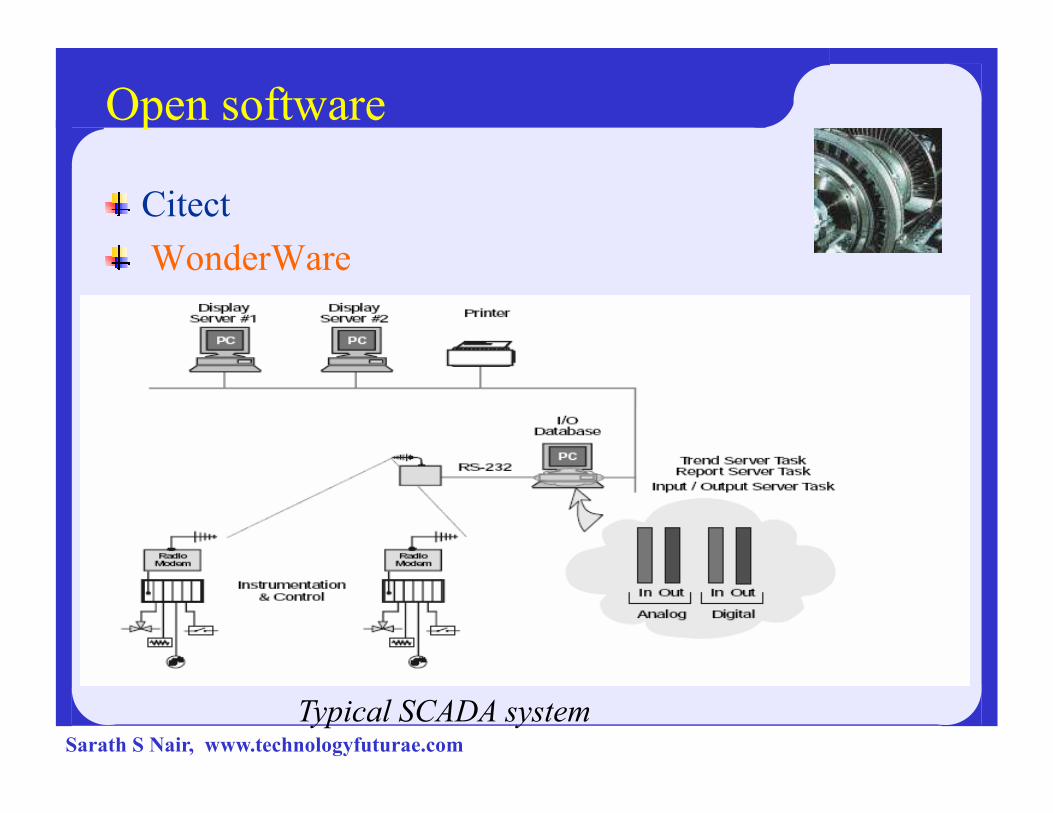
Open software
Citect
WonderWare
Typical SCADA systemSarath S Nair, www.technologyfuturae.com
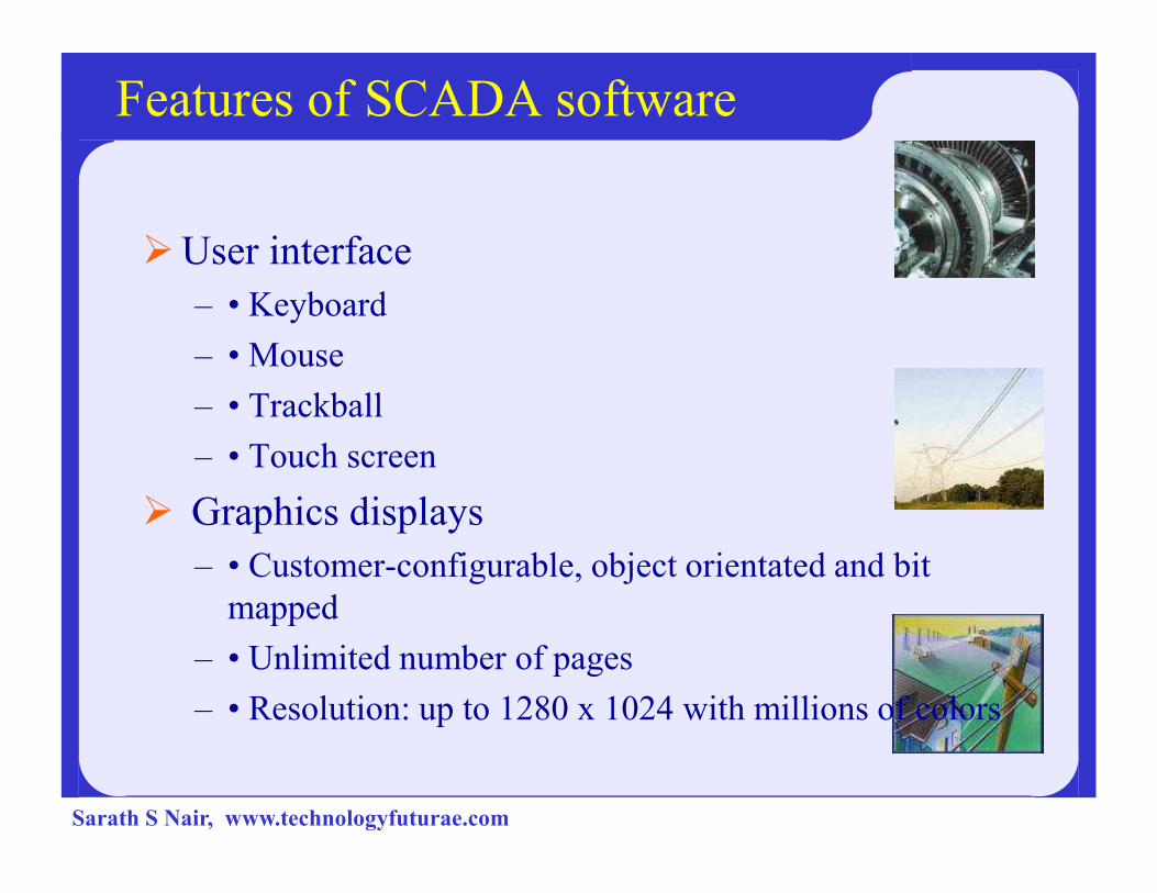
Features of SCADA software
�User interface
– • Keyboard
– • Mouse
– • Trackball
– • Touch screen– • Touch screen
� Graphics displays
– • Customer-configurable, object orientated and bit
mapped
– • Unlimited number of pages
– • Resolution: up to 1280 x 1024 with millions of colors
Sarath S Nair, www.technologyfuturae.com

� Alarms
– • Client server architecture
– • Time stamped alarms to 1 millisecond precision (or better)
– • Single network Acknowledgment and control of alarms
– • Alarms shared to all clients
– • Alarms displayed in chronological order
– • Dynamic allocation of alarm pages
– • User-defined formats and color
– • Up to four adjustable trip points for each analog alarm
– • Deviation and rate of change monitoring for analog alarms– • Deviation and rate of change monitoring for analog alarms
– • Selective display of alarms by category (256 categories)
– • Historical alarm and event logging
– • Context-sensitive help
– • On-line alarm disable and threshold modification
– • Event-triggered alarms
– • Alarm-triggered reports
– • Operator comments that can be attached to alarms
Sarath S Nair, www.technologyfuturae.com
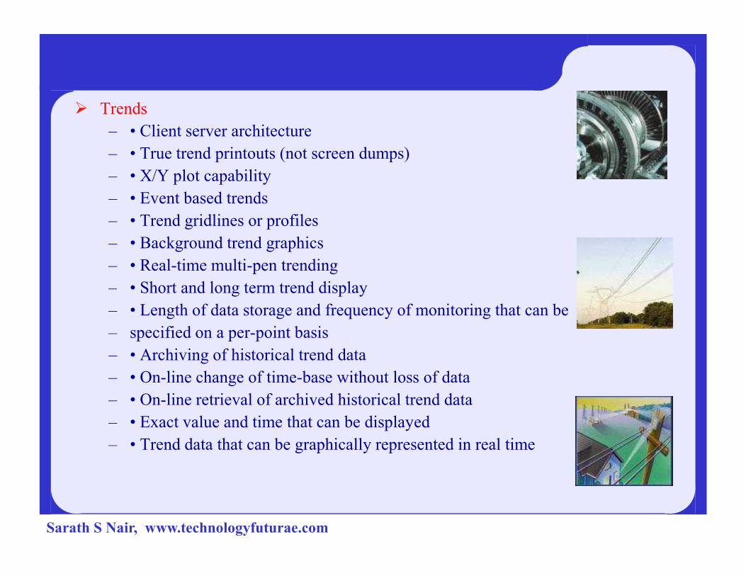
� Trends
– • Client server architecture
– • True trend printouts (not screen dumps)
– • X/Y plot capability
– • Event based trends
– • Trend gridlines or profiles
– • Background trend graphics
– • Real-time multi-pen trending
– • Short and long term trend display– • Short and long term trend display
– • Length of data storage and frequency of monitoring that can be
– specified on a per-point basis
– • Archiving of historical trend data
– • On-line change of time-base without loss of data
– • On-line retrieval of archived historical trend data
– • Exact value and time that can be displayed
– • Trend data that can be graphically represented in real time
Sarath S Nair, www.technologyfuturae.com
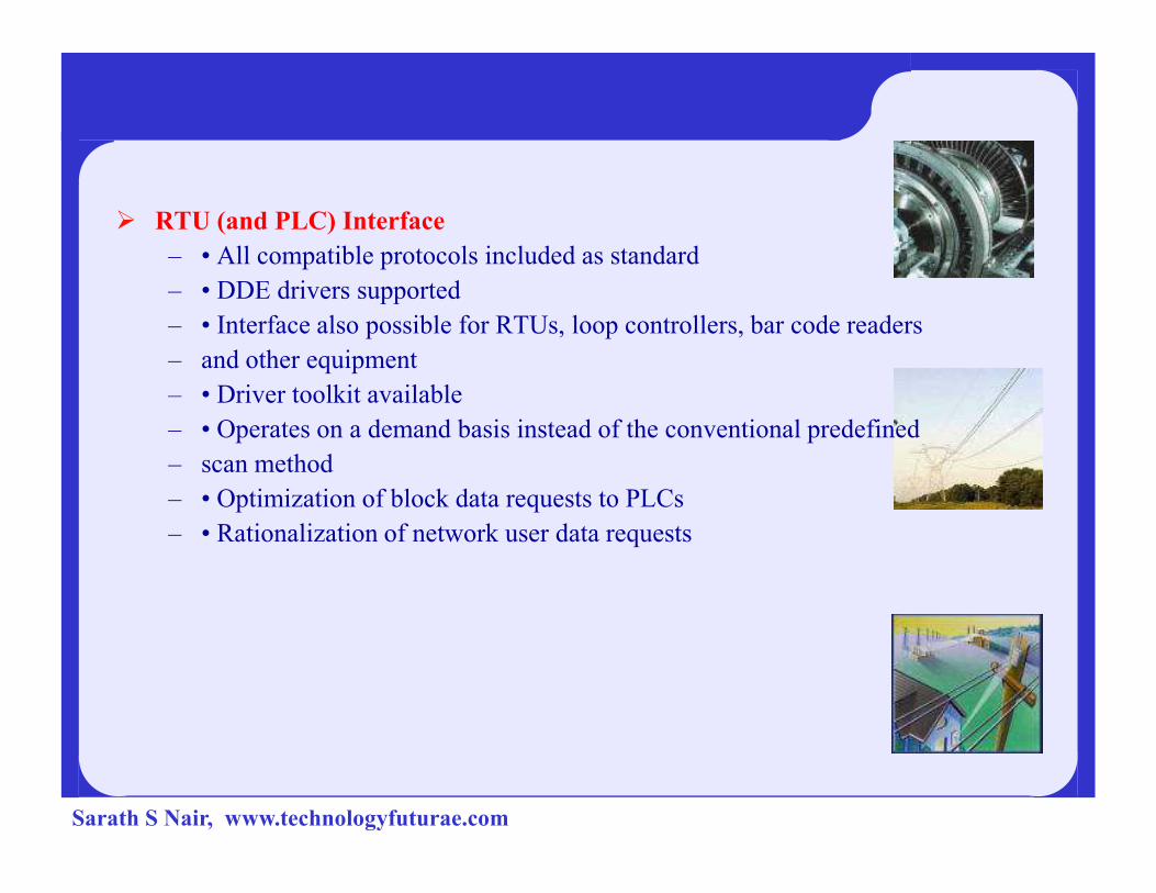
� RTU (and PLC) Interface
– • All compatible protocols included as standard
– • DDE drivers supported
– • Interface also possible for RTUs, loop controllers, bar code readers
– and other equipment
– • Driver toolkit available
– • Operates on a demand basis instead of the conventional predefined
– scan method
– • Optimization of block data requests to PLCs
– • Rationalization of network user data requests
Sarath S Nair, www.technologyfuturae.com

� Scalability
– Additional hardware can be added without replacing or
modifying existing equipment. This is limited only by the PLC architecture (typically 300 to 40,000points)
� Access to Data
– • Direct, real-time access to data by any network user
– • Third-party access to real-time data, e.g. Lotus 123 and EXCEL
– • Network DDE
– • DDE compatibility: read, write and exec
– • DDE to all IO device points
– • Clipboard
Sarath S Nair, www.technologyfuturae.com
� Database
– • ODBC driver support
– • Direct SQL commands or high level reporting
� Networking
– • Supports all NetBIOS compatible networks such as NetWare, LAN
– Manager, Windows for Workgroups, Windows NT (changed from
– existing NT)
– • Support protocols NetBEUI, IPX/SPX, TCP/IP and more
– • Centralized alarm, trend and report processing - data available from– • Centralized alarm, trend and report processing - data available from
– anywhere in the network
– • Dual networks for full LAN redundancy
– • No network configuration required (transparent)
– • May be enabled via single check box, no configuration
– • LAN licensing based on the number of users logged onto the network, not the number of nodes on the network
– • No file server required
– • Multi-user system, full communication between operators
– • RAS and WAN supported with high performance
– • PSTN dial up support
Sarath S Nair, www.technologyfuturae.com
� Fault Tolerance and Redundancy
– • Dual networks for full LAN redundancy
– • Redundancy that can be applied to specific hardware
– • Supports primary and secondary equipment configurations
– • Intelligent redundancy allows secondary equipment to contribute to
– processing load
– • Automatic changeover and recovery
– • Redundant writes to PLC with no configuration– • Redundant writes to PLC with no configuration
– • Mirrored disk I/O devices
– • Mirrored alarm servers
– • Mirrored trend servers
– • File server redundancy
Sarath S Nair, www.technologyfuturae.com
� Client/Server Distributed Processing
– • Open architecture design
– • Real-time multitasking
– • Client/server fully supported with no user configuration
– • Distributed project updates (changes reflected across network)
– • Concurrent support of multiple display nodes
– • Access any tag from any node– • Access any tag from any node
– • Access any data (trend, alarm, report) from any node
Sarath S Nair, www.technologyfuturae.com

The SCADA Software Package
� Whilst performance and efficiency of the SCADA package with the current
plant is important, the package should be easily upgradeable to handle
future requirement.
� The requirements of SCADA software packages are:
– Modifiable
– Scaleable Architecture
� Two main approaches in designing the SCADA system:� Two main approaches in designing the SCADA system:
– Centralized-a single computer or mainframe performs all plant
monitoring and all plant data is stored on one database which resides on
this computer.
– Distributed-the SCADA system is shared across several small
computers (usually PCs).
Sarath S Nair, www.technologyfuturae.com
Tasks performed by SCADA system
4 • Input/Output Task -This program is the interface between the control and monitoring system and the plant floor.
4 • Alarm Task - This manages all alarms by detecting digital alarm points and comparing the values of analog alarm points to alarm thresholds.
4 • Trends Task - The trends task collects data to be monitored over time.
4 • Reports Task - Reports are produced from plant data. These reports can be periodic, event triggered or activated by the operator.
4 • Display Task - This manages all data to be monitored by the operator and all 4 • Display Task - This manages all data to be monitored by the operator and all control actions requested by the operator.
Sarath S Nair, www.technologyfuturae.com
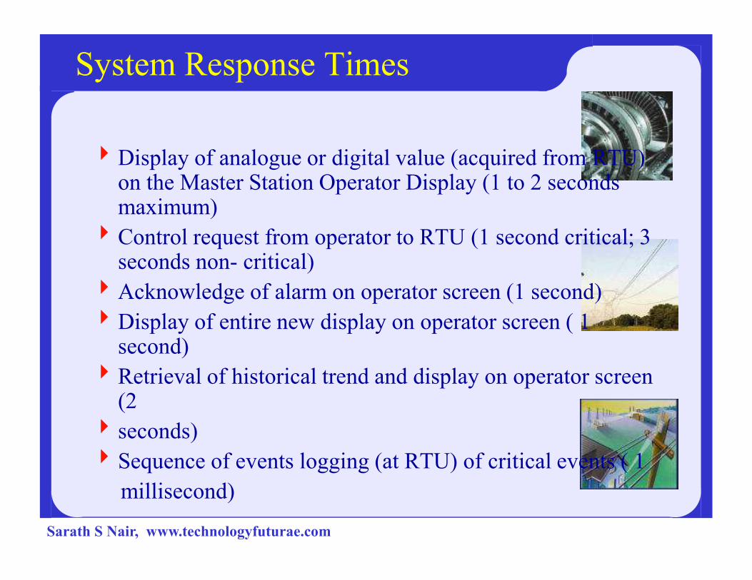
System Response Times
4Display of analogue or digital value (acquired from RTU) on the Master Station Operator Display (1 to 2 seconds maximum)
4Control request from operator to RTU (1 second critical; 3 seconds non- critical)
4Acknowledge of alarm on operator screen (1 second)4Acknowledge of alarm on operator screen (1 second)
4Display of entire new display on operator screen ( 1 second)
4Retrieval of historical trend and display on operator screen (2
4 seconds)
4Sequence of events logging (at RTU) of critical events ( 1
millisecond)
Sarath S Nair, www.technologyfuturae.com
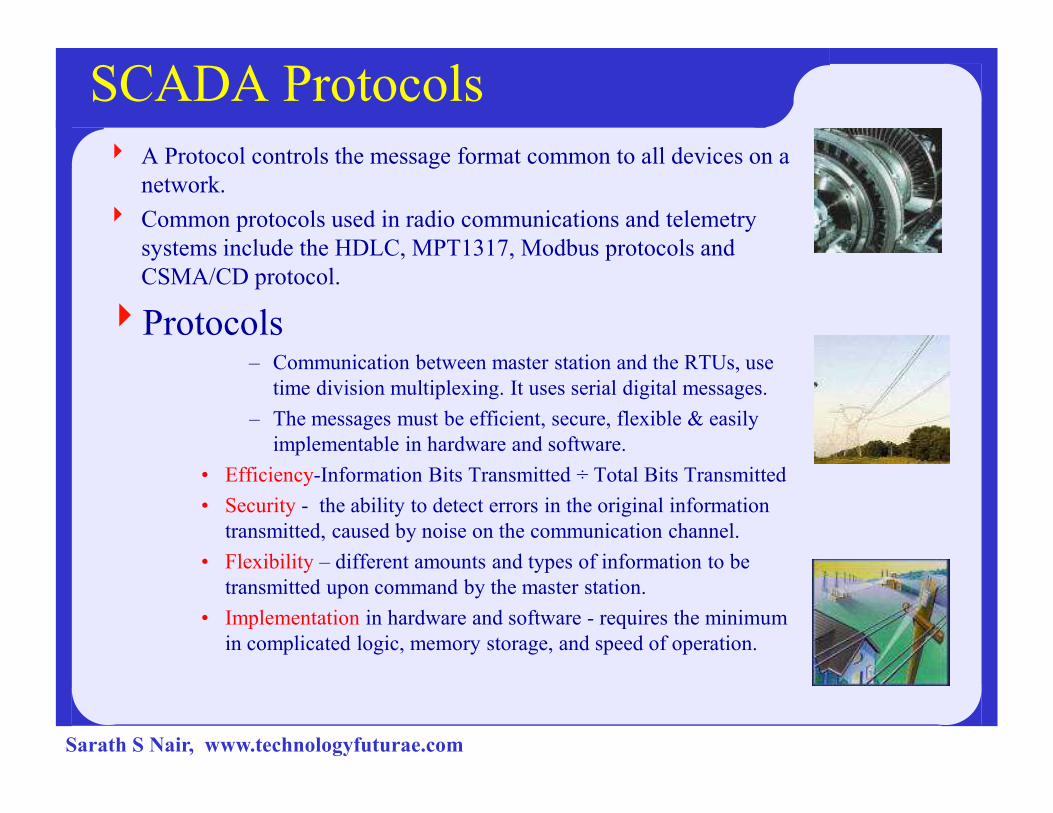
SCADA Protocols
4 A Protocol controls the message format common to all devices on a
network.
4 Common protocols used in radio communications and telemetry
systems include the HDLC, MPT1317, Modbus protocols and
CSMA/CD protocol.
4Protocols– Communication between master station and the RTUs, use
time division multiplexing. It uses serial digital messages.
– The messages must be efficient, secure, flexible & easily – The messages must be efficient, secure, flexible & easily
implementable in hardware and software.
• Efficiency-Information Bits Transmitted ÷ Total Bits Transmitted
• Security - the ability to detect errors in the original information
transmitted, caused by noise on the communication channel.
• Flexibility – different amounts and types of information to be
transmitted upon command by the master station.
• Implementation in hardware and software - requires the minimum
in complicated logic, memory storage, and speed of operation.
Sarath S Nair, www.technologyfuturae.com
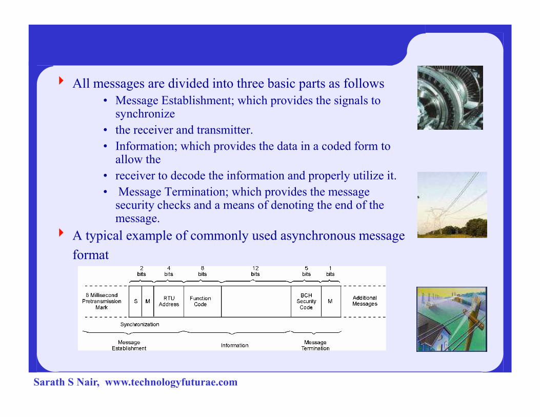
4 All messages are divided into three basic parts as follows
• Message Establishment; which provides the signals to synchronize
• the receiver and transmitter.
• Information; which provides the data in a coded form to allow the
• receiver to decode the information and properly utilize it.
• Message Termination; which provides the message security checks and a means of denoting the end of the security checks and a means of denoting the end of the message.
4 A typical example of commonly used asynchronous message
format
Sarath S Nair, www.technologyfuturae.com
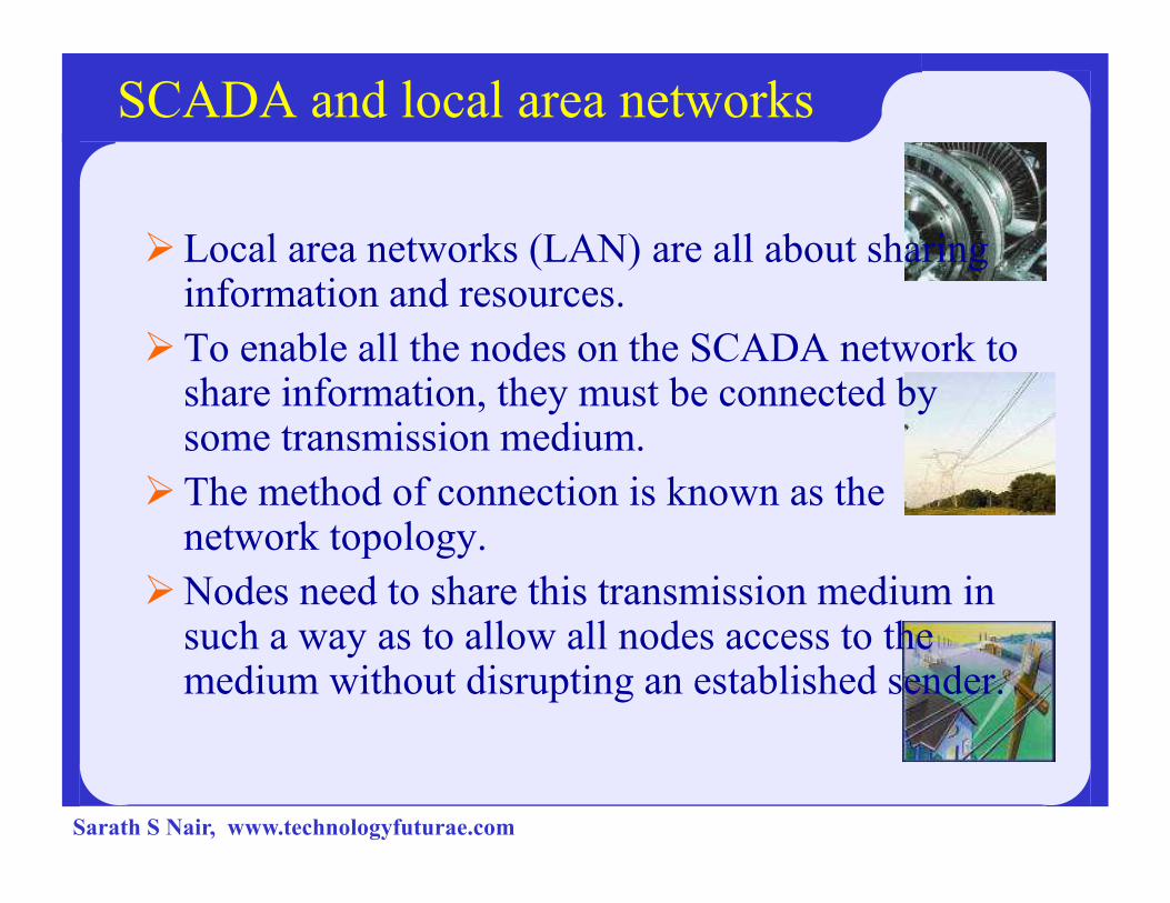
SCADA and local area networks
�Local area networks (LAN) are all about sharing information and resources.
�To enable all the nodes on the SCADA network to share information, they must be connected by some transmission medium. some transmission medium.
�The method of connection is known as the network topology.
�Nodes need to share this transmission medium in such a way as to allow all nodes access to the medium without disrupting an established sender.
Sarath S Nair, www.technologyfuturae.com
� A LAN is a communication path between computers, file-servers, terminals, workstations, and various other intelligent peripheral equipments, which are generally referred to as devices or hosts.
� A LAN allows access for devices to be shared by several users, with full connectivity between all stations on the network.
� A LAN is usually owned and administered by a private owner and is located within a localized group of buildings.
� Ethernet is the most widely use LAN today because it is cheap and easy to use Connection of the SCADA network
Continued…
use Connection of the SCADA network
� LAN allows anyone within the company with the right software and permission, to access the system. Since the data is held in a database, the user can be limited to reading the information. Security issues are obviously a concern, but can be addressed
Sarath S Nair, www.technologyfuturae.com
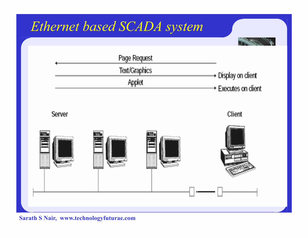
Ethernet based SCADA system
Sarath S Nair, www.technologyfuturae.com
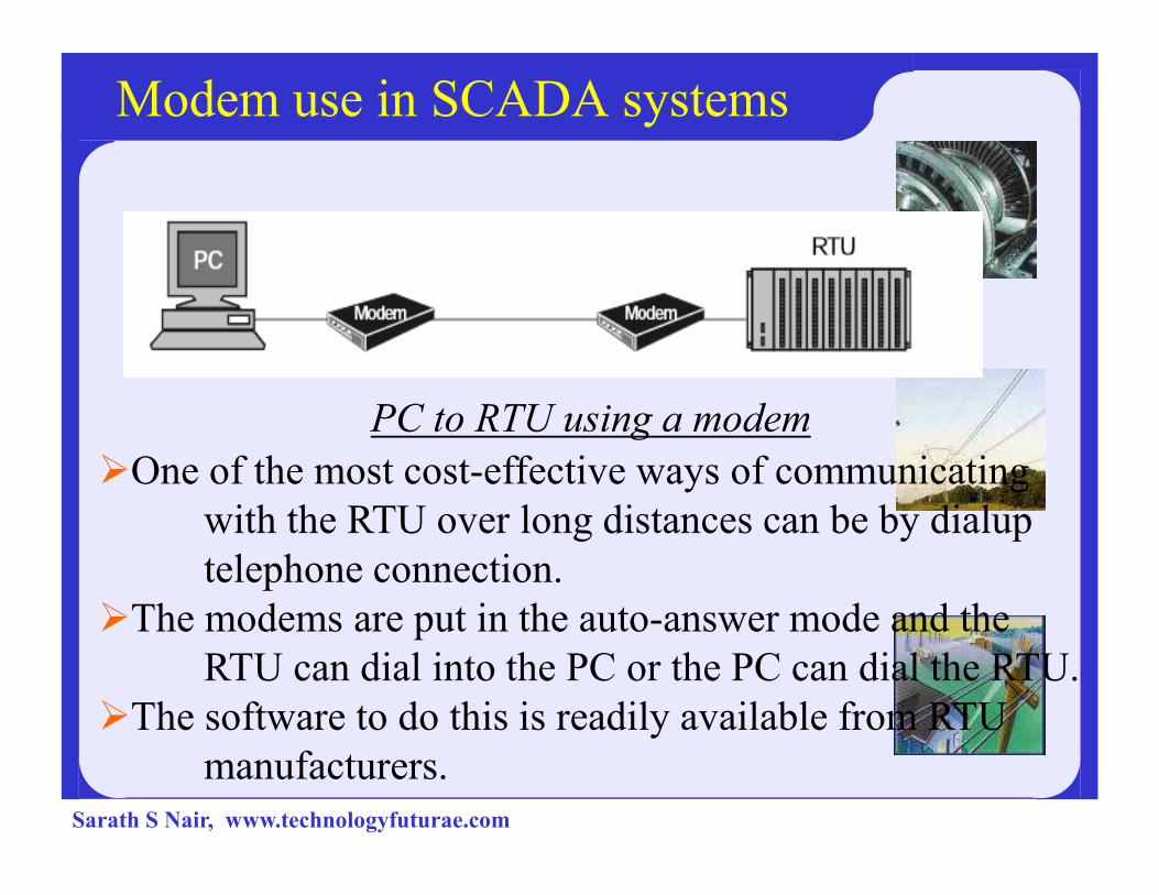
Modem use in SCADA systems
PC to RTU using a modem
�One of the most cost-effective ways of communicating �One of the most cost-effective ways of communicating
with the RTU over long distances can be by dialup
telephone connection.
�The modems are put in the auto-answer mode and the
RTU can dial into the PC or the PC can dial the RTU.
�The software to do this is readily available from RTU
manufacturers.
Sarath S Nair, www.technologyfuturae.com
System Troubleshooting
� The RTU and component modules
� Analog input modules
� Digital input module
� Interface from RTU to PLC (RS-232/RS-485)
� Privately owned cable
� Switched telephone line
� Analog or digital data links
� The master sites� The master sites
� The central site
� The operator station and software
Sarath S Nair, www.technologyfuturae.com
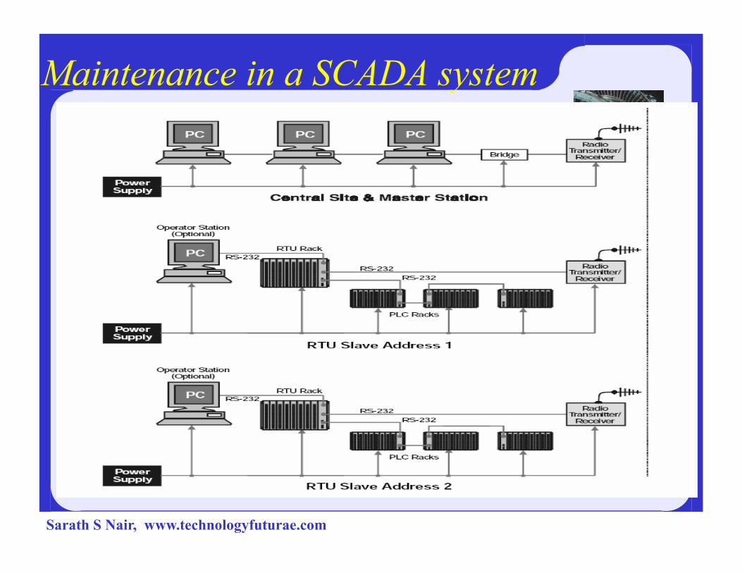
Maintenance in a SCADA system
Sarath S Nair, www.technologyfuturae.com
System implementation
�Consideration should be given to integrating new SCADA systems into existing communication networks in order to avoid the substantial cost of setting up new infrastructure and communications facilities.
�This may be carried out through existing LANs, �This may be carried out through existing LANs, private telephone systems or existing radio systems used for mobile vehicle communications.
� Careful engineering analysis must be carried out to ensure that overlaying of the SCADA system on to an existing communication network does not degrade or interfere with the existing facilities.
Sarath S Nair, www.technologyfuturae.com

Comparison of SCADA, DCS, PLCComparison of SCADA, DCS, PLC
Sarath S Nair, www.technologyfuturae.com
SCADA system
�A SCADA (or supervisory control and data acquisition) system means a system consisting of a number of remote terminal units (or RTUs) collecting field data connected back to a master station via a communications system.
�The master station displays the acquired data and also allows the operator to perform remote control tasks.
�The accurate and timely data (normally real-time) allows for optimization of the operation of the plant and process.
Sarath S Nair, www.technologyfuturae.com

Distributed control system
�The data acquisition and control functions are performed by a number of distributed microprocessor-based units situated near to the devices being controlled or the instrument from which data is being gathered.
�DCS systems have evolved into systems providing �DCS systems have evolved into systems providing very sophisticated analog (e.g. loop) control capability.
�A closely integrated set of operator interfaces (or man machine interfaces) is provided to allow for easy system configurations and operator control.
�The data highway is normally capable of fairly high speeds (typically 1 Mbps up to 10 Mbps).
Sarath S Nair, www.technologyfuturae.com

Distributed control system
Sarath S Nair, www.technologyfuturae.com
Programmable logic controller
4Replaced hardwired relays with a combination of
ladder– logic software and solid state electronic
input and output modules.
4They are often used in the implementation of a
SCADA RTU as they offer a standard hardware SCADA RTU as they offer a standard hardware
solution, which is very economically priced.
Sarath S Nair, www.technologyfuturae.com

Programmable logic controller system
Sarath S Nair, www.technologyfuturae.com
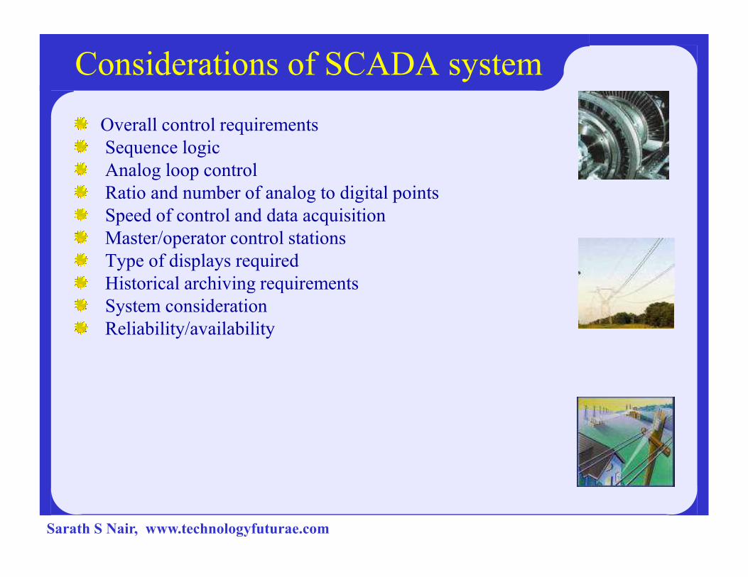
Considerations of SCADA system
Overall control requirements
Sequence logic
Analog loop control
Ratio and number of analog to digital points
Speed of control and data acquisition
Master/operator control stations
Type of displays required
Historical archiving requirementsHistorical archiving requirements
System consideration
Reliability/availability
Sarath S Nair, www.technologyfuturae.com

Continued….
Speed of communications/update time/system scan rates
System redundancy
Expansion capability
Application software and modeling
Sarath S Nair, www.technologyfuturae.com

Benefits of SCADA
Improved operation of the plant or process resulting in savings due to optimization of the system
Increased productivity of the personnel
Improved safety of the system due to better information and improved controlinformation and improved control
Protection of the plant equipment
Safeguarding the environment from a failure of the system
Sarath S Nair, www.technologyfuturae.com
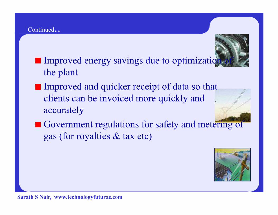
Continued..
Improved energy savings due to optimization of
the plant
Improved and quicker receipt of data so that
clients can be invoiced more quickly and
accuratelyaccurately
Government regulations for safety and metering of
gas (for royalties & tax etc)
Sarath S Nair, www.technologyfuturae.com
EXAMPLES
SCADA SYSTEMS
Sarath S Nair, www.technologyfuturae.com

Level
transmitter
senses the
water level
and pass it
to RTU
MOTOR ONMOTOR OFF
WATER
FROM
THE
RTU RTU
REGIONAL CONTROL CENTRE
THE
MAIN
HEADER
Sarath S Nair, www.technologyfuturae.com
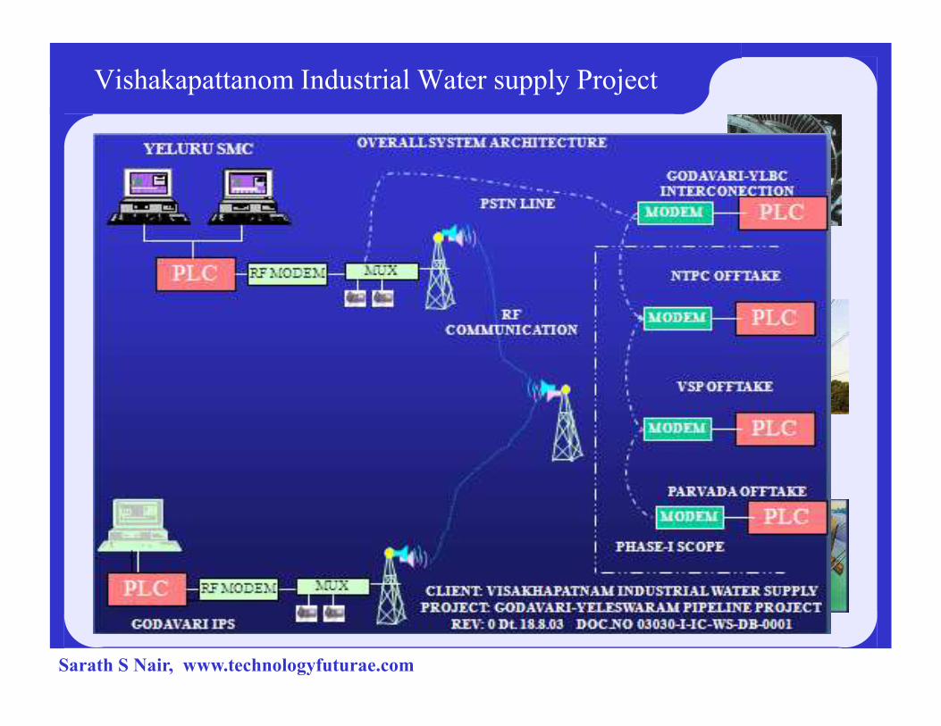
Vishakapattanom Industrial Water supply Project
Sarath S Nair, www.technologyfuturae.com

ENERGY & AUTOMATION
NITC SCADA Laboratory
ENERGY & AUTOMATION
Training Programme on Industrial AutomationSarath S Nair, www.technologyfuturae.com

Introduction
SCADA
Overview of SCADA Laboratory
Transmission Line Model
Overview
Interface with SCADA
IED’s
Experiments
Contents
Experiments
Distribution Line ModelOverview
Interface with SCADA
Experiments
Scope
Conclusion
Sarath S Nair, www.technologyfuturae.com

Supervisory Control and Data Acquisition (SCADA)
SCADA is a software program that gathers real time
information for process control of field equipment. SCADA can
be used in industries such as telecommunications, power
systems, oil and gas refining, water and waste control and
transportation.
Main Components of SCADA
Introduction
Main Components of SCADA
Control Center
Intelligent Electronic Devices (IEDs)
Programmable Logic Controllers (PLCs)
Electrical Transducers
Sarath S Nair, www.technologyfuturae.com
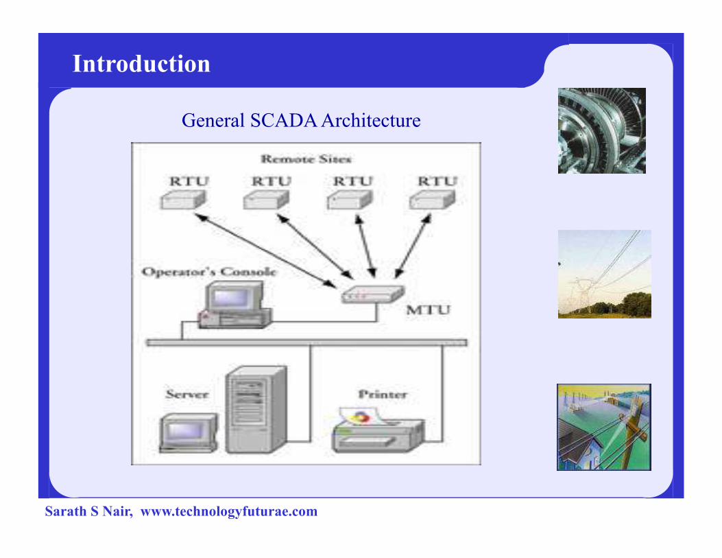
General SCADA Architecture
Introduction
Sarath S Nair, www.technologyfuturae.com
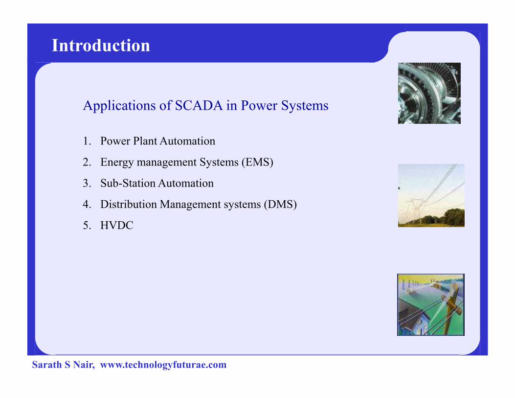
Applications of SCADA in Power Systems
1. Power Plant Automation
2. Energy management Systems (EMS)
3. Sub-Station Automation
4. Distribution Management systems (DMS)
Introduction
4. Distribution Management systems (DMS)
5. HVDC
Sarath S Nair, www.technologyfuturae.com
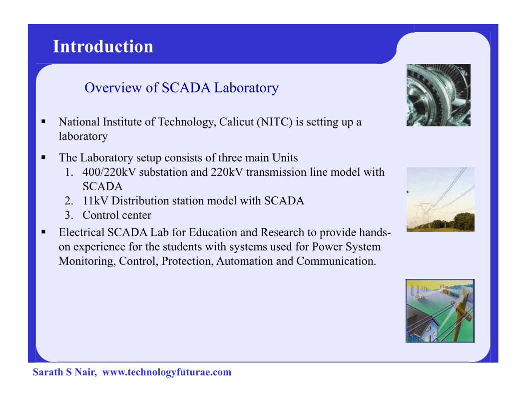
Overview of SCADA Laboratory
� National Institute of Technology, Calicut (NITC) is setting up a
laboratory
� The Laboratory setup consists of three main Units
1. 400/220kV substation and 220kV transmission line model with
SCADA
2. 11kV Distribution station model with SCADA
Introduction
2. 11kV Distribution station model with SCADA
3. Control center
� Electrical SCADA Lab for Education and Research to provide hands-
on experience for the students with systems used for Power System
Monitoring, Control, Protection, Automation and Communication.
Sarath S Nair, www.technologyfuturae.com

Transmission Line Model
Sarath S Nair, www.technologyfuturae.com

Overview of TLM
Transmission Line Model
The model consists of 400/220 kV receiving substation with a
220 kV out going line.
One typical 220 kV transmission line also is modeled for a
distance of 200 KM.
The Communication System is built on the newest substation
Communication Architecture of IEC 61850.Communication Architecture of IEC 61850.
Load Model
(R,L &C Load)
200 KM
Transmission Line Model
(8 pi Sections each of 25 km)
400/220 kV SS
Sarath S Nair, www.technologyfuturae.com

Fuse
3-Ph Supply
L, 1 kVAR, 0.33 kVAR/Ph,5 A, 38.5 mH/Ph
Contactor 110 V4 pole 32 A
Contactor 110 V4 pole, 32 A
R, 1 kW, 0.33 kW/Ph5 A, 110 V
12.1 Ohm/Ph
Load Model
3 ph, 4 Wire12 ohm Dimmer
3 ph, 4 Wire12 ohm Dimmer
MCB
32 A
400/220 kV Substation Model
220 kV, 200 KMTransmission Line
Model
C1
415/110 V1 KVA, 12.5%
EM 3
Prot CT 2.5/1 A
MeteringCT 2.5/1
Metering
CT 5/1 AMeteringCT 5/1 A
C2 C3 IN
R
XTransmission Line8-Pi sections
Relay 1
Breaker4 pole 32 A
C4
C3
C2
C1Fault Throw
Switch
EM 1
C10
Capacitor Bank0.1 KVA/Ph0.3 KVA/3-Ph
10 Nos.
Series Compensation
1 KVA, 12.5%
EM 2
CBM
Auxiliary Supply415/110 V
500 VA, 1-Ph
Sarath S Nair, www.technologyfuturae.com
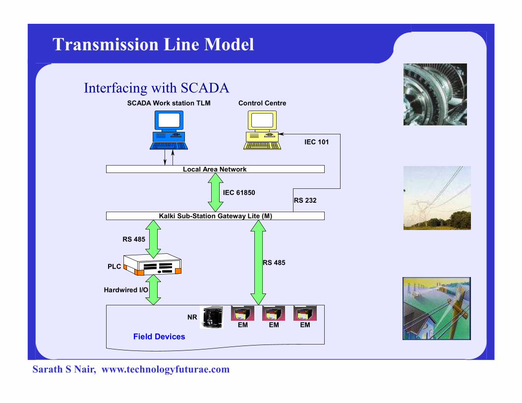
Transmission Line Model
Interfacing with SCADA
Local Area Network
SCADA Work station TLM Control Centre
IEC 61850
IEC 101
RS 232
Kalki Sub-Station Gateway Lite (M)
EM EM EMNR
Field Devices
RS 485
RS 232
Hardwired I/O
RS 485
PLC
Sarath S Nair, www.technologyfuturae.com

Sarath S Nair, www.technologyfuturae.com
Transmission Line Model
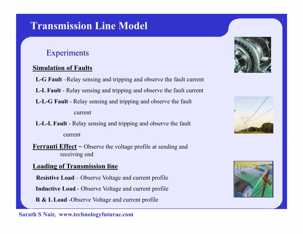
Experiments
Simulation of Faults
L-G Fault –Relay sensing and tripping and observe the fault current
L-L Fault - Relay sensing and tripping and observe the fault current
L-L-G Fault - Relay sensing and tripping and observe the fault
current
L-L-L Fault - Relay sensing and tripping and observe the fault
current
Ferranti Effect – Observe the voltage profile at sending and
receiving end
Loading of Transmission line
Resistive Load – Observe Voltage and current profile
Inductive Load - Observe Voltage and current profile
R & L Load -Observe Voltage and current profile
Sarath S Nair, www.technologyfuturae.com

VAR Compensation
Series Compensation - Observe the bus voltage profile
Shunt Compensation
Regulation of bus voltage – Observe the bus voltage profile
Loading of transformer - Observe the current profile and relay sensing,
Transmission Line Model
Experiments
Loading of transformer - Observe the current profile and relay sensing,
tripping.
Sudden Load rejection – Voltage regulation at sending end.
Operation of OLTC transformer – Voltage regulation at sending end.
Sarath S Nair, www.technologyfuturae.com

IED’s
4PLC
(Programmable Logic Controller)
4Relay
4Energy Meter
Sarath S Nair, www.technologyfuturae.com

4 Introduction of PLC
4Basic PLC Operation
4Example
4Advantages of PLC
4GE Fanuc PLCs4GE Fanuc PLCs
4VersaMax Micro
4Terminologies
4Basic Requirements
Sarath S Nair, www.technologyfuturae.com
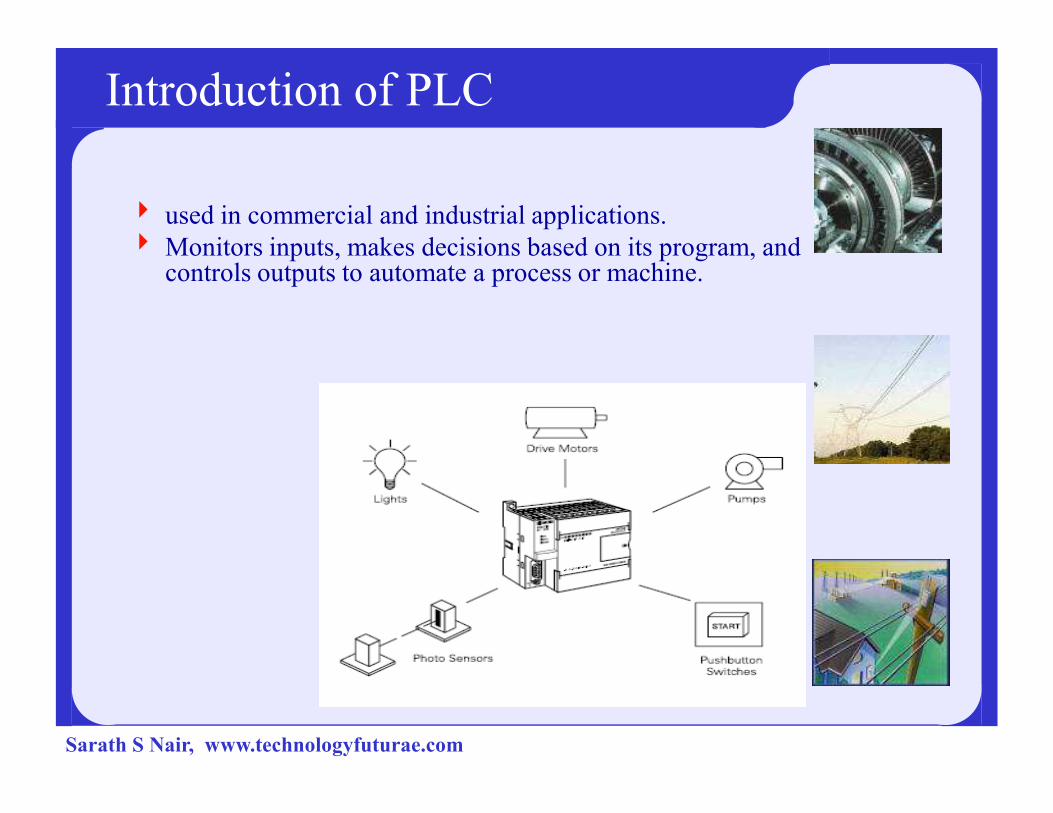
Introduction of PLC
4 used in commercial and industrial applications.
4 Monitors inputs, makes decisions based on its program, and controls outputs to automate a process or machine.
Sarath S Nair, www.technologyfuturae.com
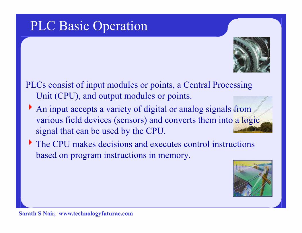
PLC Basic Operation
PLCs consist of input modules or points, a Central Processing
Unit (CPU), and output modules or points.
4An input accepts a variety of digital or analog signals from
various field devices (sensors) and converts them into a logic various field devices (sensors) and converts them into a logic
signal that can be used by the CPU.
4The CPU makes decisions and executes control instructions
based on program instructions in memory.
Sarath S Nair, www.technologyfuturae.com

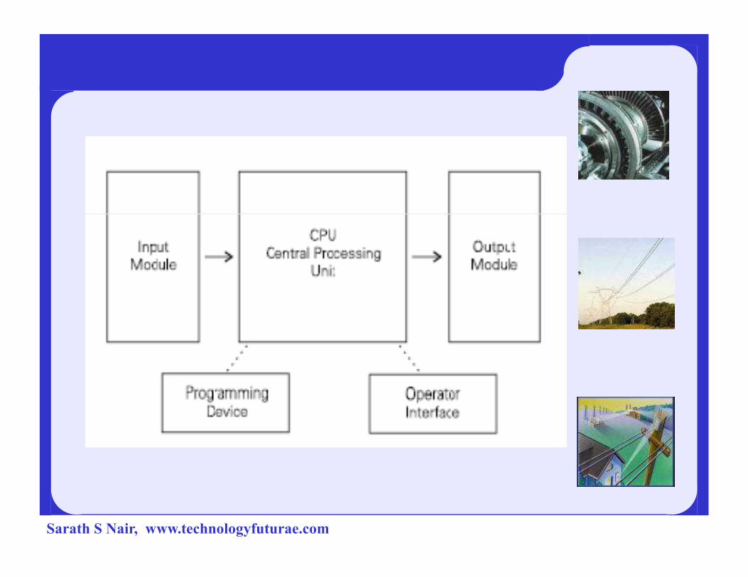
4Output modules convert control instructions from the CPU
into a digital or analog signal that can be used to control
various field devices (actuators).
4A programming device is used to input the desired
instructions. These instructions determine what the PLC instructions. These instructions determine what the PLC
will do for a specific input.
4An operator interface device allows process information to
be displayed and new control parameters to be entered.
Sarath S Nair, www.technologyfuturae.com
Sarath S Nair, www.technologyfuturae.com

Example:
Pushbuttons (sensors), in this simple example,
connected to PLC inputs, can be used to start and
stop a motor connected to a PLC through a
motor starter (actuator).
Sarath S Nair, www.technologyfuturae.com
Advantages of PLC
4Smaller physical size than hard-wire solutions
4 Easier and faster to make changes
4 PLCs have integrated diagnostics and override functions
4Diagnostics are centrally available
4Applications can be immediately documented4Applications can be immediately documented
4Applications can be duplicated faster and less expensively
Sarath S Nair, www.technologyfuturae.com
GEFanuc PLCs
GEFanuc makes several PLC product lines
They are:
490-30 series
490-70 series
4Micro/ Nano4Micro/ Nano
Sarath S Nair, www.technologyfuturae.com

Micro
4This is referred to as a Micro PLC because of its small
size.
4The Micro has a brick design which means that the power
supply and I/O are on-board.
4The Micro can be used on smaller, stand-alone applications The Micro can be used on smaller, stand-alone applications
such as elevators, car washes, or mixing machines.
Sarath S Nair, www.technologyfuturae.com

Micro
Sarath S Nair, www.technologyfuturae.com
Terminology
The language of PLCs consists of a commonly
used set of terms; an understanding of these terms is
necessary.
4Sensor: A sensor is a device that converts a physical4Sensor: A sensor is a device that converts a physical
condition into an electrical signal for use by the PLC.
Sensors are connected to the input of a PLC.
Sarath S Nair, www.technologyfuturae.com
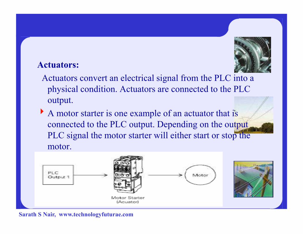
Actuators:
Actuators convert an electrical signal from the PLC into a
physical condition. Actuators are connected to the PLC
output.
4A motor starter is one example of an actuator that is A motor starter is one example of an actuator that is
connected to the PLC output. Depending on the output
PLC signal the motor starter will either start or stop the
motor.
Sarath S Nair, www.technologyfuturae.com
Basic Requirements
In order to create or change a program, the following items
are needed:
4 PLC
4 Programming Device
4 Programming Software4 Programming Software
4Connector Cable
Sarath S Nair, www.technologyfuturae.com
Distribution Sub-Station Model
Sarath S Nair, www.technologyfuturae.com
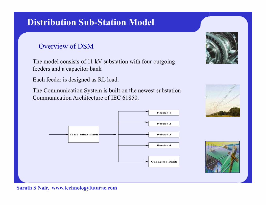
Overview of DSM
The model consists of 11 kV substation with four outgoing
feeders and a capacitor bank
Each feeder is designed as RL load.
The Communication System is built on the newest substation
Communication Architecture of IEC 61850.
Distribution Sub-Station Model
11 kV SubStation
Feeder 2
Feeder 1
Feeder 4
Feeder 3
Capacitor Bank
Sarath S Nair, www.technologyfuturae.com

Fuse1-Ph
Supply
MCB1-Ph
16 A
16 A
16 A
Feeder 1
Feeder 2
Feeder 3
L, 4 taps230 V, 50 Ohm
L, 4 taps230 V, 50 Ohm
R 1KW230 V, 52.9 Ohm
R, 1 KW230 V, 52.9 Ohm
R, 1 KW230 V, 52.9 Ohm
L, 4 taps230 V, 50 Ohm
Prot CT
25/1 A
Metr CT
25/1 A
Metr CT
5/1 A
Metr CT
5/1 A16 A
415/230 V, 1:1
5 KVA, 1-Ph, 5%
32 A
Metr CT
5/1 A
Relay
11 KV Distribution Model
EM
EM
EM
EM
IN
F1
F2
F3
16 AFeeder 4
230 V, 50 Ohm
R, 1 KW230 V, 52.9 Ohm
L, 4 taps230 V, 50 Ohm
Metr CT
5/1 A
Relay
EM
Capacitor Bank0.5 KVAR
1-Ph, LT, 5 Nos.
16 A
16 A
16 A
16 A
16 A
F4
CB1CB
CB2
CB3
CB4
CB5
Sarath S Nair, www.technologyfuturae.com
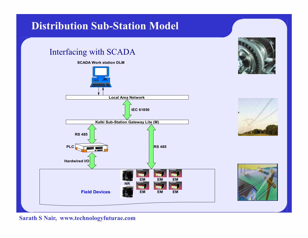
Interfacing with SCADA
Distribution Sub-Station Model
Local Area Network
SCADA Work station DLM
IEC 61850
EM
RS 485
EM
Kalki Sub-Station Gateway Lite (M)
EM EM
EM
EM
NR
Field Devices
Hardwired I/O
RS 485
PLC
Sarath S Nair, www.technologyfuturae.com

Experiments
Relay Coordination
Voltage Regulation
Demand Side Management
Load Shedding
Distribution Sub-Station Model
Sarath S Nair, www.technologyfuturae.com
Experiments in SCADA
Distribution Sub-Station Model
Experiments in SCADA
Sarath S Nair, www.technologyfuturae.com
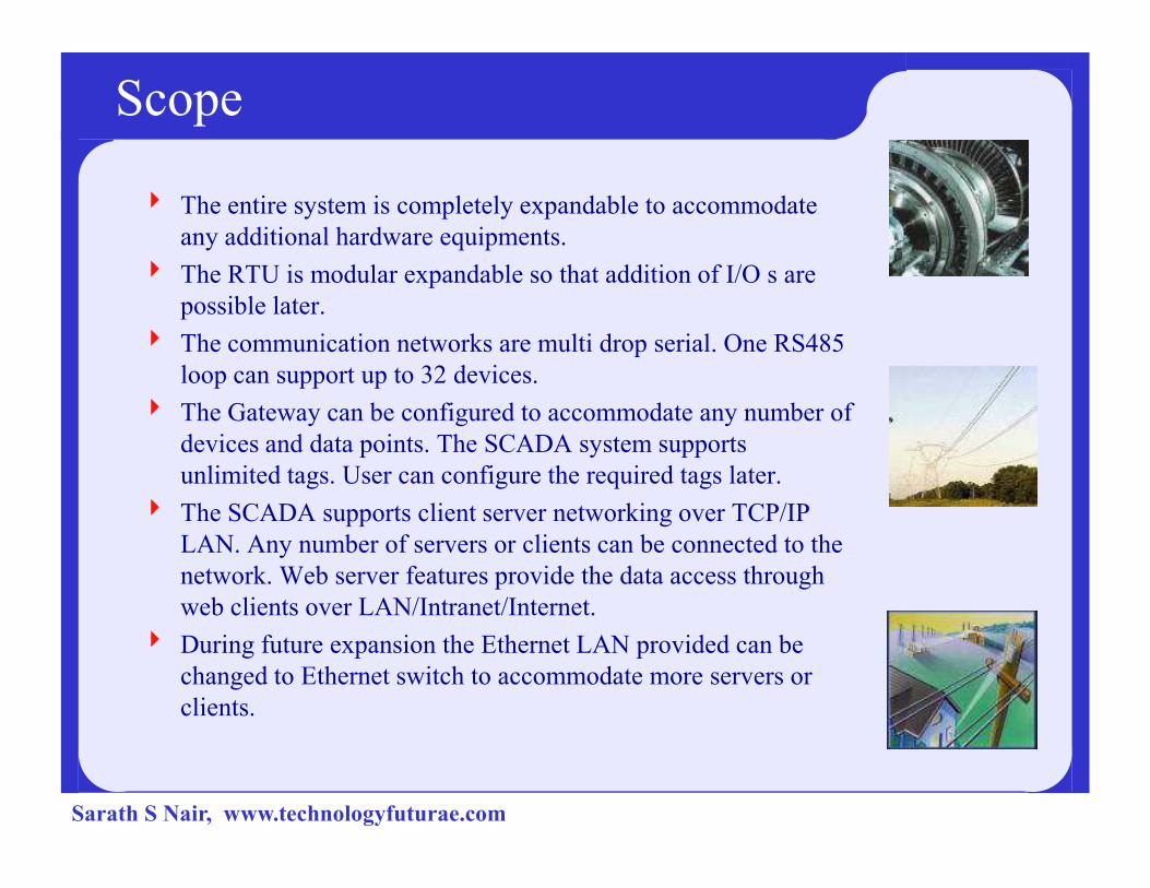
Scope
4 The entire system is completely expandable to accommodate
any additional hardware equipments.
4 The RTU is modular expandable so that addition of I/O s are
possible later.
4 The communication networks are multi drop serial. One RS485
loop can support up to 32 devices.
4 The Gateway can be configured to accommodate any number of
devices and data points. The SCADA system supports devices and data points. The SCADA system supports
unlimited tags. User can configure the required tags later.
4 The SCADA supports client server networking over TCP/IP
LAN. Any number of servers or clients can be connected to the
network. Web server features provide the data access through
web clients over LAN/Intranet/Internet.
4 During future expansion the Ethernet LAN provided can be
changed to Ethernet switch to accommodate more servers or
clients.
Sarath S Nair, www.technologyfuturae.com
Conclusion
� This SCADA Lab serves the purpose of providing hands-on
experience for the students with systems used for Power System
Monitoring, Control, Protection, Automation and Monitoring, Control, Protection, Automation and
Communication.
Sarath S Nair, www.technologyfuturae.com

SCADA AND ITS SCADA AND ITS
IMPLEMENTATIONIMPLEMENTATION
IN INDIAN POWER SECTORIN INDIAN POWER SECTORIN INDIAN POWER SECTORIN INDIAN POWER SECTOR
Sarath S Nair, www.technologyfuturae.com
Power Sector SCADA
Used to monitor & manage the Power System Networks-
Generation – Transmission – Distribution – Metering –
Billing etc
Sarath S Nair, www.technologyfuturae.com

Sarath S Nair, www.technologyfuturae.com

TYPICAL HIERARCHICAL CONTROL CENTRE SETUP
ERLDC WRLDC SRLDC NRLDC NERLDC5 Nos.
NLDC
RTU RTU RTU
SUB LDC SUB LDC SUB LDC
SLDC SLDC SLDC32 Nos.
41 Nos.
1160 Nos.
Sarath S Nair, www.technologyfuturae.com
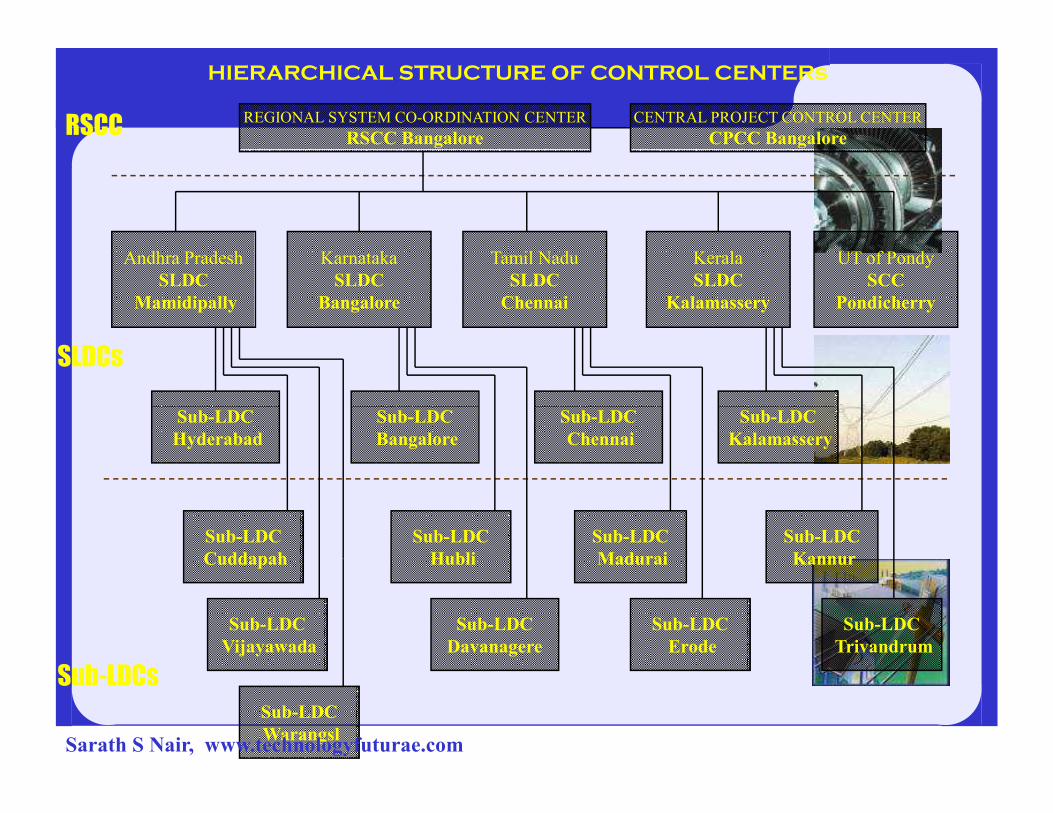
RSCCREGIONAL SYSTEM CO-ORDINATION CENTER
RSCC Bangalore
CENTRAL PROJECT CONTROL CENTER
CPCC Bangalore
SLDCs
Andhra Pradesh
SLDC
Mamidipally
Karnataka
SLDC
Bangalore
Tamil Nadu
SLDC
Chennai
Kerala
SLDC
Kalamassery
UT of Pondy
SCC
Pondicherry
Sub-LDC Sub-LDC Sub-LDC Sub-LDC
HIERARCHICAL STRUCTURE OF CONTROL CENTERs
Sub-LDCs
Sub-LDC
Hyderabad
Sub-LDC
Cuddapah
Sub-LDC
Bangalore
Sub-LDC
Chennai
Sub-LDC
Kalamassery
Sub-LDC
Vijayawada
Sub-LDC
Warangsl
Sub-LDC
Hubli
Sub-LDC
Davanagere
Sub-LDC
Madurai
Sub-LDC
Erode
Sub-LDC
Kannur
Sub-LDC
Trivandrum
Sarath S Nair, www.technologyfuturae.com
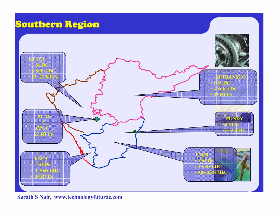
Southern Region Southern Region
KPTCL
• 1 SLDC
• 3 Sub-LDC
• 22+21 RTUs APTRANSCO
• 1 SLDC
• 4 Sub-LDC
• 82 RTUs
TNEB
• 1 SLDC
• 3 Sub-LDC
• 40+35 RTUs
KSEB
• 1 SLDC
• 3 Sub-LDC
• 30 RTUs
PONDY
• 1 SCC
• 5+9 RTUs
RLDC
+
CPCC
22 RTUs
Sarath S Nair, www.technologyfuturae.com

Regional Level SCADA Overview
Sarath S Nair, www.technologyfuturae.com
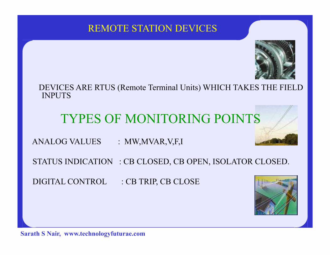
REMOTE STATION DEVICES
DEVICES ARE RTUS (Remote Terminal Units) WHICH TAKES THE FIELD INPUTS
TYPES OF MONITORING POINTS
ANALOG VALUES : MW,MVAR,V,F,I
STATUS INDICATION : CB CLOSED, CB OPEN, ISOLATOR CLOSED.
DIGITAL CONTROL : CB TRIP, CB CLOSE
Sarath S Nair, www.technologyfuturae.com
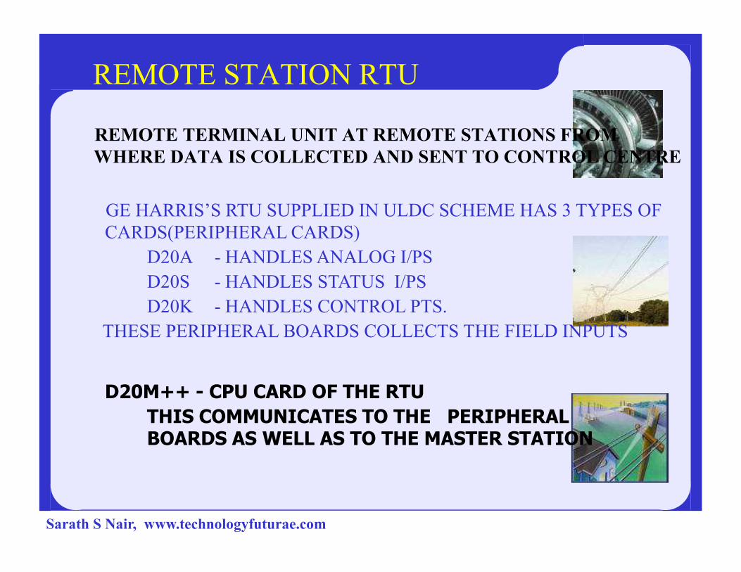
REMOTE STATION RTU
REMOTE TERMINAL UNIT AT REMOTE STATIONS FROM
WHERE DATA IS COLLECTED AND SENT TO CONTROL CENTRE
GE HARRIS’S RTU SUPPLIED IN ULDC SCHEME HAS 3 TYPES OF
CARDS(PERIPHERAL CARDS)
D20A - HANDLES ANALOG I/PS
D20S - HANDLES STATUS I/PSD20S - HANDLES STATUS I/PS
D20K - HANDLES CONTROL PTS.
THESE PERIPHERAL BOARDS COLLECTS THE FIELD INPUTS
D20M++ - CPU CARD OF THE RTU
THIS COMMUNICATES TO THE PERIPHERAL BOARDS AS WELL AS TO THE MASTER STATION
Sarath S Nair, www.technologyfuturae.com

Manjeswaram Mylatti Kanhirode
Nallalam Areakode Kuttiady
Kaniyampetta Palakkad Shornur
Madakathara Chalakudy Poringal
Sholayar Idamalayar Pallivasal
Sengulam Neriamangalam Lower Periyar
RTU STATIONS
Sengulam Neriamangalam Lower Periyar
Idukki Kalamassery Brahmapuram
Pallom Edappon Kundara
Sabarigiri Kakkad Edamon
Pothencode Parassala Punnapra
Kayamkulam
(Central Sector)
TVM 400kV (PGCIL) Thaliparambu
Sarath S Nair, www.technologyfuturae.com
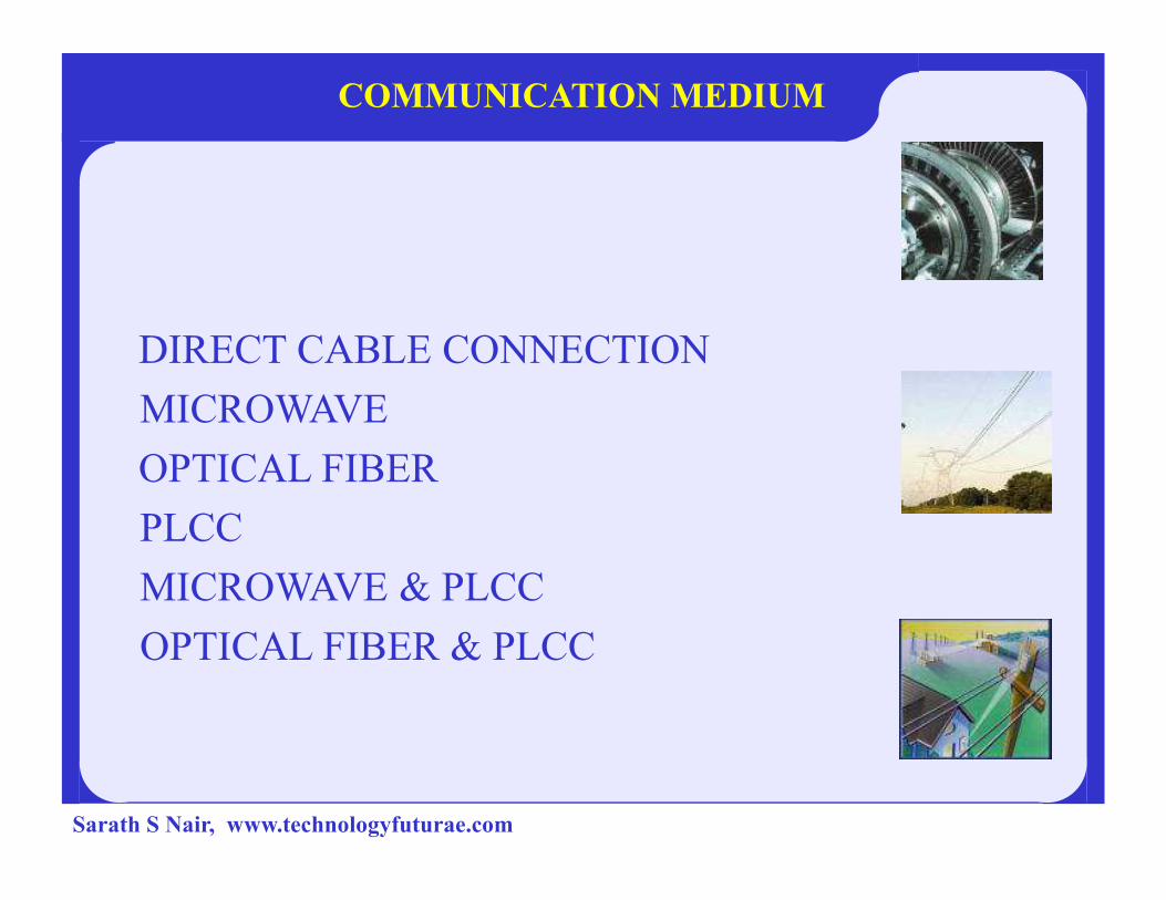
COMMUNICATION MEDIUM
DIRECT CABLE CONNECTION
MICROWAVE
OPTICAL FIBEROPTICAL FIBER
PLCC
MICROWAVE & PLCC
OPTICAL FIBER & PLCC
Sarath S Nair, www.technologyfuturae.com

COMMUNICATION MEDIUM
CD
WT
FEP RTU
POWER LINE
MOD
EMDC FEP RTUMOD
EM
PLCCCD
WT
(DIRECT CABLE)
LAN 2
MOD
EMFEP PLCC PLCC
MOD
EMRTU
FEP MUX MW RTUMUXMWMW
Sarath S Nair, www.technologyfuturae.com

COMMUNICATION MEDIUM
FEP MUX OLTE RTUMUXOLTEOFCOFC
NODAL STATIONS
VB PCOD PRPY KDRA KYLM PLLM VIKM KLSY
CHDYMDRAARKDKNRD
OFC
MW
Sarath S Nair, www.technologyfuturae.com

Parassala
Pothencode
Edamon
VB TVM KND KYM PLM KSY
Edappon
KakkadEdamon
Kundara Sabarigiri
BDPP
Idukki
Pallivasal
SengulamNeriamangalam
PallomKsy
Punnapra
WIDEBAND LOCATIONS AND RTUs
TCRNARKDKNR CLDY
Chldy
Idlyr
ShlyrMDRA
LP
KJKD Arkd
KnyptaKZDE
Mnjm
MLTYKnr
Kttdy
PorlSHNR
Sarath S Nair,
www.technologyfuturae.com
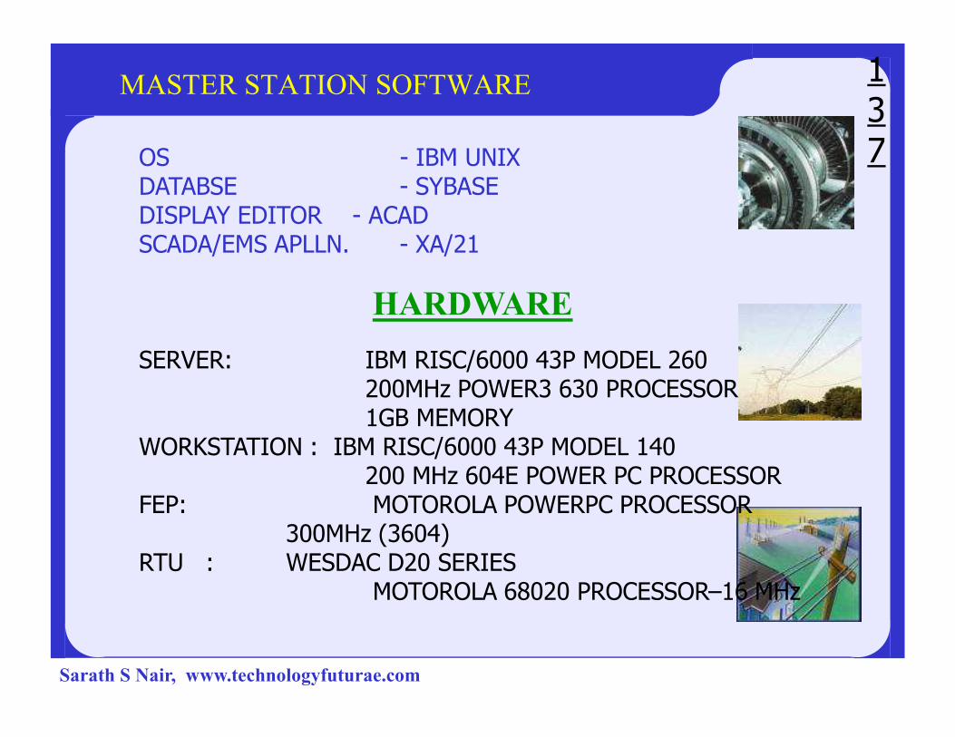
MASTER STATION SOFTWARE
OS - IBM UNIXDATABSE - SYBASEDISPLAY EDITOR - ACAD SCADA/EMS APLLN. - XA/21
HARDWARE
SERVER: IBM RISC/6000 43P MODEL 260
137
SERVER: IBM RISC/6000 43P MODEL 260200MHz POWER3 630 PROCESSOR1GB MEMORY
WORKSTATION : IBM RISC/6000 43P MODEL 140200 MHz 604E POWER PC PROCESSOR
FEP: MOTOROLA POWERPC PROCESSOR 300MHz (3604)
RTU : WESDAC D20 SERIESMOTOROLA 68020 PROCESSOR–16 MHz
Sarath S Nair, www.technologyfuturae.com

MASTER STATIONSub LDC
AP/WS1 AP/WS2 FEP 1 FEP 2
LAN 1
LAN 2
ROUTERS
WAN
LAN 1
LAN 2
SCADA
SERVER
DATA
SERVER
BACKUP
SERVER
EMS
SERVER 1
EMS
SERVER2
EMS
BACKUP
WS 1 WS 2 WS 3 WS 4
AP 1
FEP 1
AP 2 AP 3 AP 4 AP 5 AP 6
FEP 2
LAN 1
LAN 2
ROUTERS
WAN
SLDC
Sarath S Nair, www.technologyfuturae.com
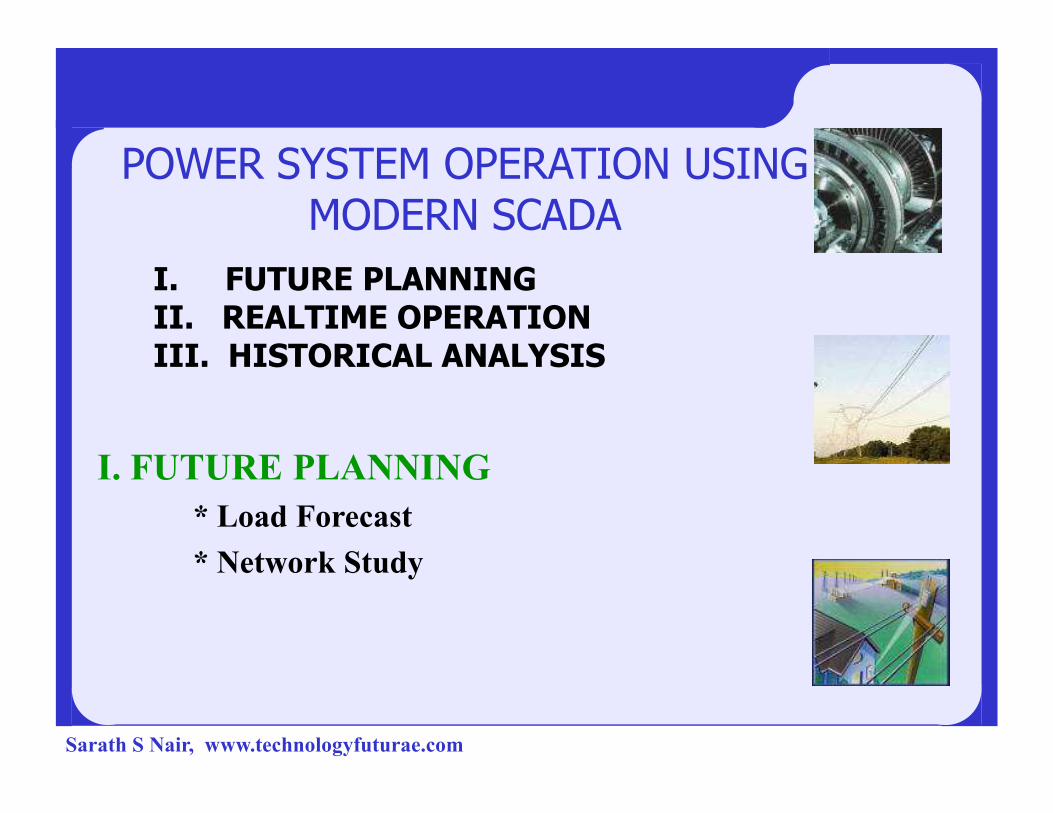
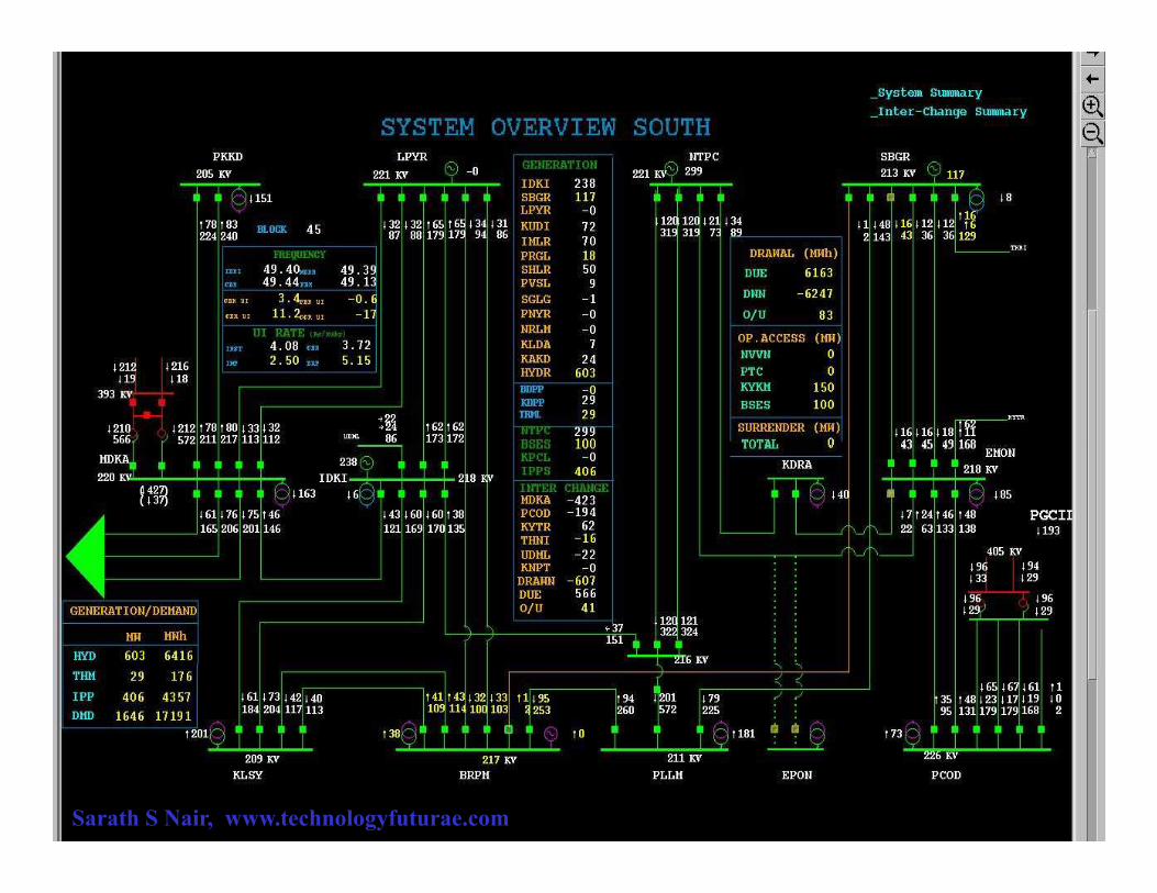
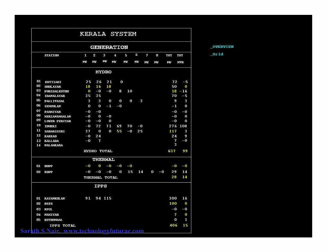
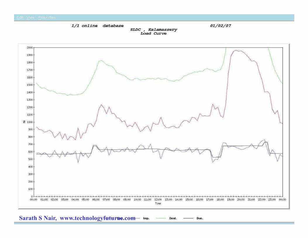
POWER SYSTEM OPERATION USING MODERN SCADA
I. FUTURE PLANNING II. REALTIME OPERATION III. HISTORICAL ANALYSIS
I. FUTURE PLANNING
* Load Forecast
* Network Study
Sarath S Nair, www.technologyfuturae.com
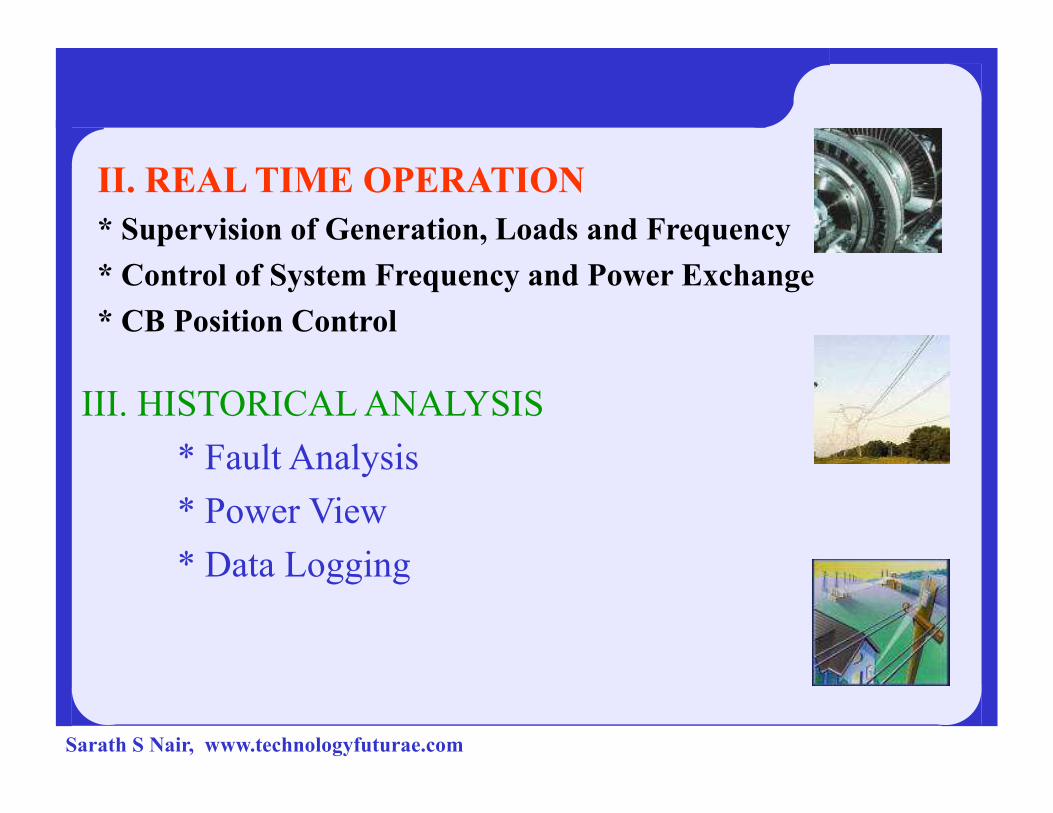
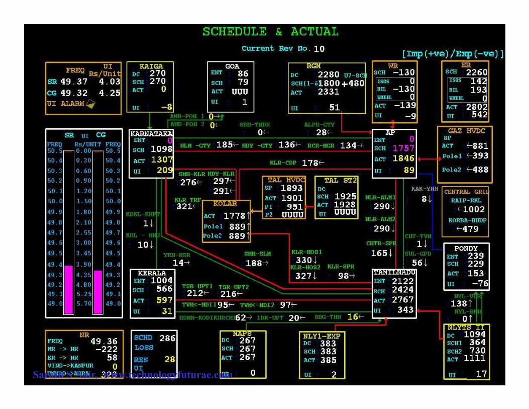
II. REAL TIME OPERATION
* Supervision of Generation, Loads and Frequency
* Control of System Frequency and Power Exchange
* CB Position Control
III. HISTORICAL ANALYSISIII. HISTORICAL ANALYSIS
* Fault Analysis
* Power View
* Data Logging
Sarath S Nair, www.technologyfuturae.com
Sarath S Nair, www.technologyfuturae.com

Sarath S Nair, www.technologyfuturae.com
Sarath S Nair, www.technologyfuturae.com
Sarath S Nair, www.technologyfuturae.com
Sarath S Nair, www.technologyfuturae.com

Thank You
Sarath S Nair, www.technologyfuturae.com

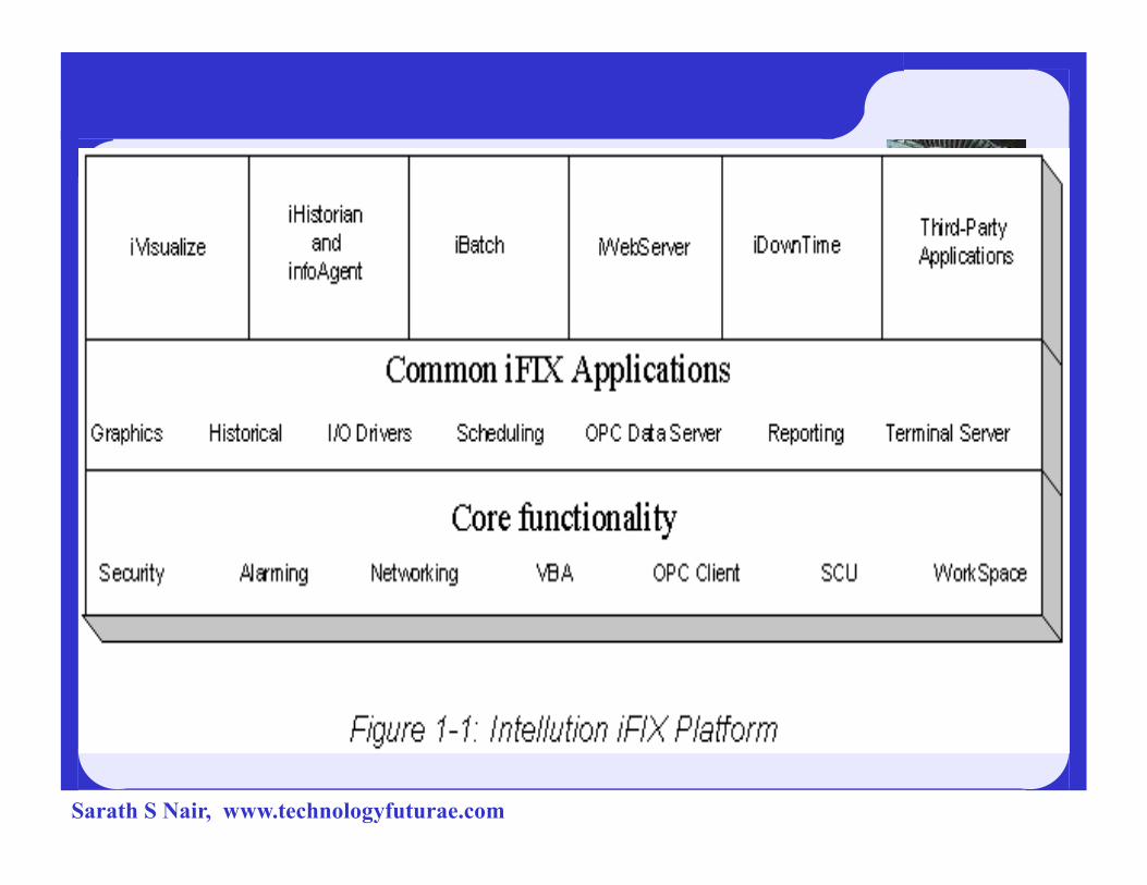
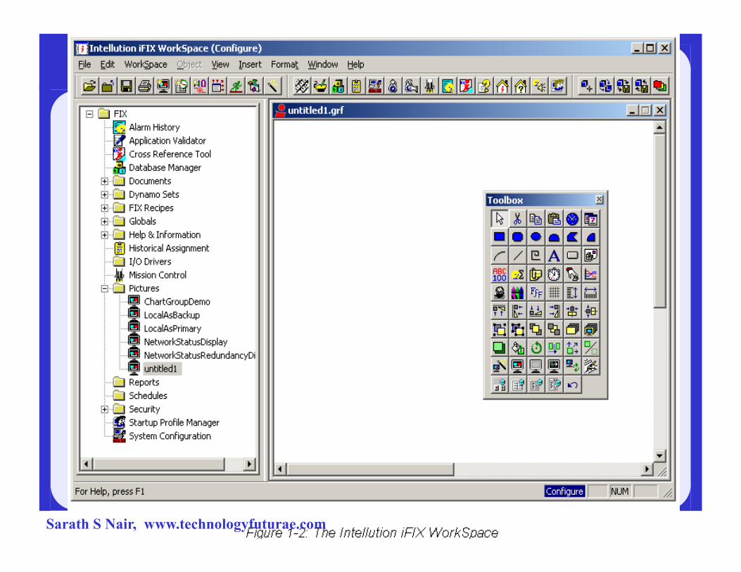
GE Fanuc IFIX Software
4 iFIX® is the Windows-based HMI/SCADA component
of GE Fanuc's family of software automation products
4Allow easy integration and interoperability between your
plant floor and business systems.
4The SCADA portion of iFIX provides monitoring, 4The SCADA portion of iFIX provides monitoring,
supervisory control, alarming, and control functions.
4 Provides a distributed architecture.
4 iFIX is built on standard technologies, such as ActiveX,
OPC, VBA, and Component Object Model (COM).
Sarath S Nair, www.technologyfuturae.com
Sarath S Nair, www.technologyfuturae.com
Sarath S Nair, www.technologyfuturae.com
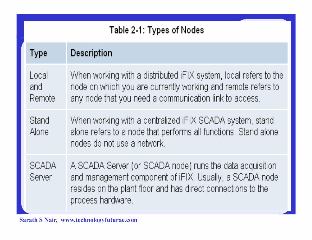
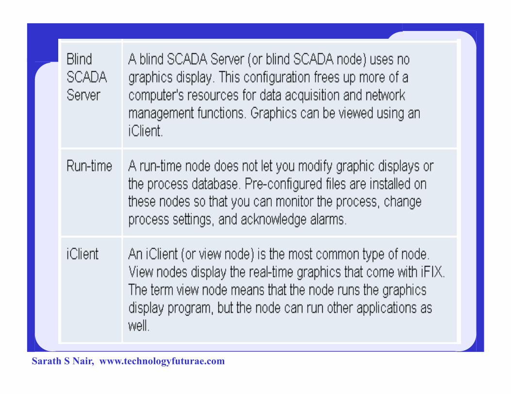
Understanding the iFIX Nodes
Sarath S Nair, www.technologyfuturae.com
Sarath S Nair, www.technologyfuturae.com
Sarath S Nair, www.technologyfuturae.com
Sarath S Nair, www.technologyfuturae.com

Sarath S Nair, www.technologyfuturae.com

Sarath S Nair, www.technologyfuturae.com
Sarath S Nair, www.technologyfuturae.com
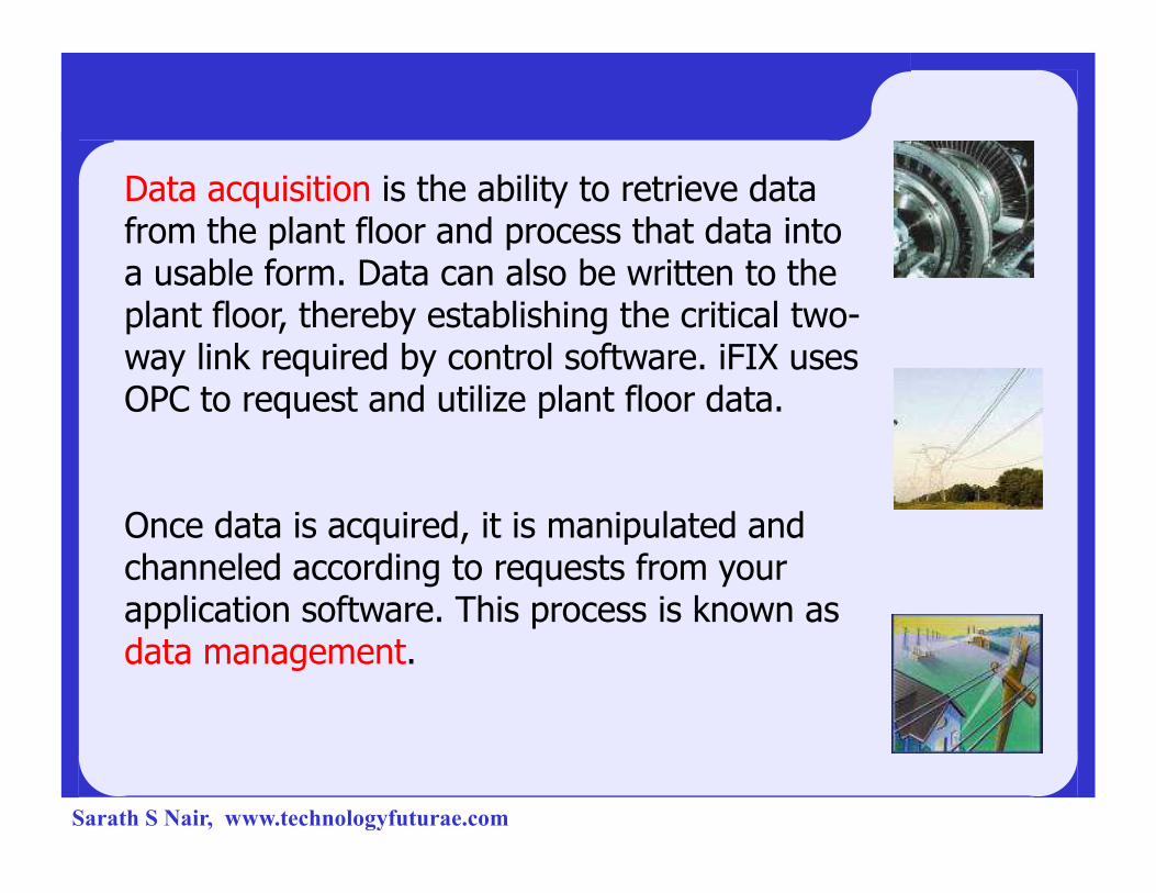
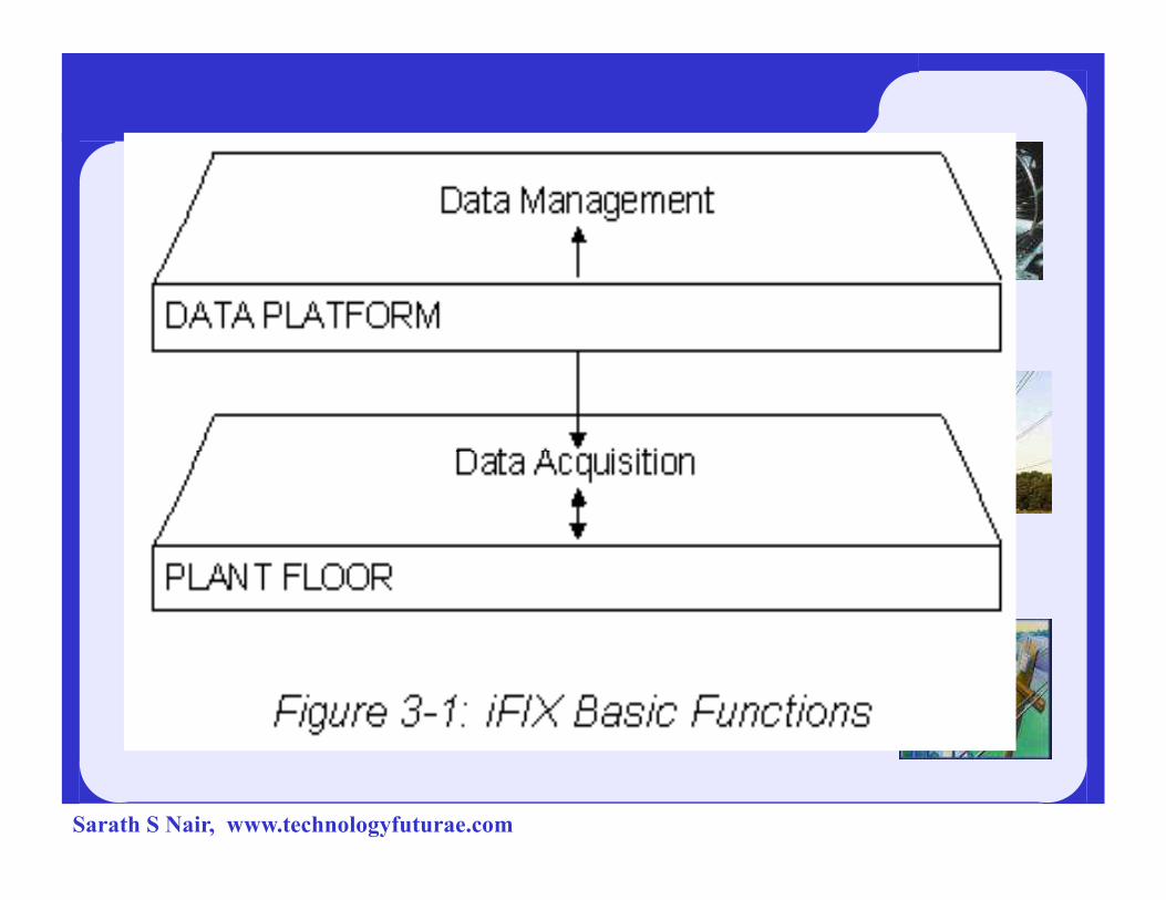
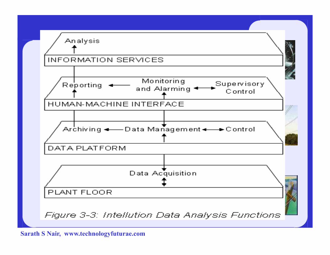
Data acquisition is the ability to retrieve data from the plant floor and process that data into a usable form. Data can also be written to the plant floor, thereby establishing the critical two-way link required by control software. iFIX uses OPC to request and utilize plant floor data.
Once data is acquired, it is manipulated and channeled according to requests from your application software. This process is known as data management.
Sarath S Nair, www.technologyfuturae.com
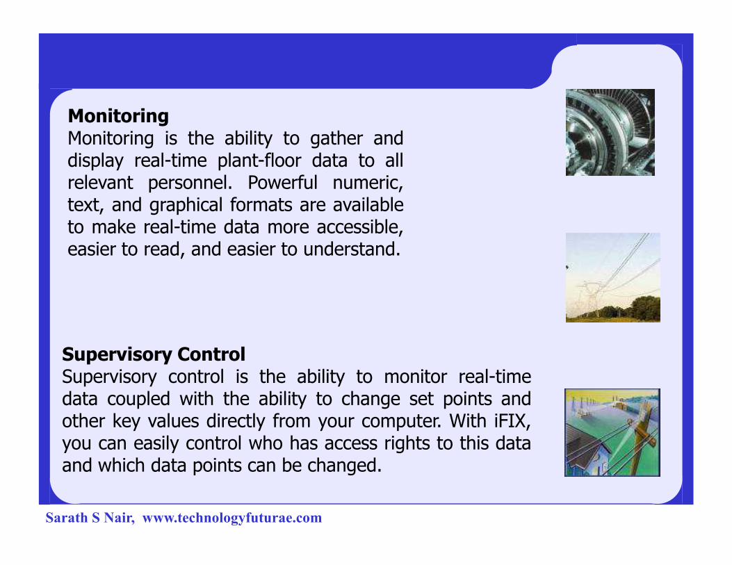
MonitoringMonitoring is the ability to gather anddisplay real-time plant-floor data to allrelevant personnel. Powerful numeric,text, and graphical formats are availableto make real-time data more accessible,easier to read, and easier to understand.
Supervisory ControlSupervisory control is the ability to monitor real-timedata coupled with the ability to change set points andother key values directly from your computer. With iFIX,you can easily control who has access rights to this dataand which data points can be changed.
Sarath S Nair, www.technologyfuturae.com
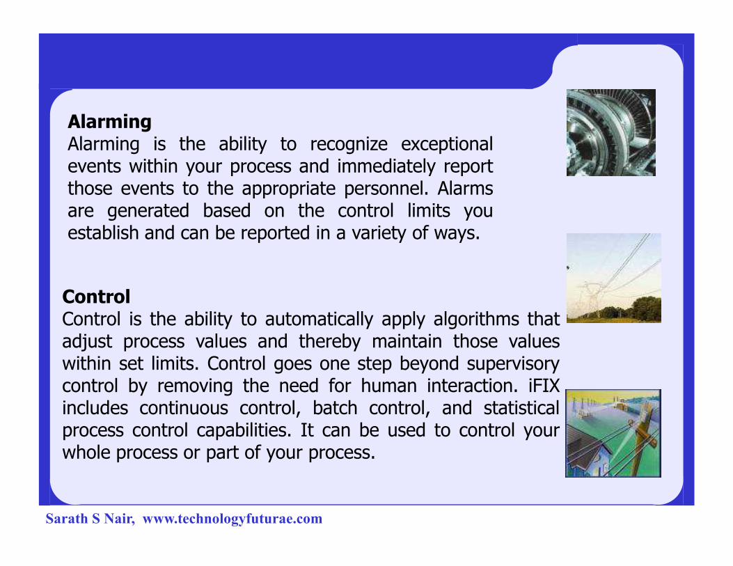
AlarmingAlarming is the ability to recognize exceptionalevents within your process and immediately reportthose events to the appropriate personnel. Alarmsare generated based on the control limits youestablish and can be reported in a variety of ways.
ControlControl is the ability to automatically apply algorithms thatadjust process values and thereby maintain those valueswithin set limits. Control goes one step beyond supervisorycontrol by removing the need for human interaction. iFIXincludes continuous control, batch control, and statisticalprocess control capabilities. It can be used to control yourwhole process or part of your process.
Sarath S Nair, www.technologyfuturae.com

Reporting FunctionsReal-time data is only one level ofinformation processing. Many plants requirethe ability to report or store real-time datafor later analysis. iFIX allows you to use anythird-party reporting application that supportsODBC queries to create reports based oncritical system and process information. Thecritical system and process information. Thefollowing figure illustrates the reportingfunctions.
Sarath S Nair, www.technologyfuturae.com
Sarath S Nair, www.technologyfuturae.com
Acknowledgement
4Industrial Power Group, NIT calicut,
INDIA
4Kalki Communications
Sarath S Nair, www.technologyfuturae.com

THANK YOU
Sarath S Nair, www.technologyfuturae.com


![Presentazione standard di PowerPoint€¦ · %Scad C] TOT portafC] Scad C] Scad 120 A Scad 120 C] Scad 150 A Scad 150 72468 261 618 45 go 188 527 C] Scad 180 A Scad 180 C] Scad 30](https://static.cupdf.com/doc/110x72/60aafa6f3697c86f175cace5/presentazione-standard-di-scad-c-tot-portafc-scad-c-scad-120-a-scad-120-c-scad.jpg)


![NFI – INDUSTRIAL AUTOMATION TRAINING ACADEMYnfiautomation.org/Six Months Industrial Automation Syllabus.pdf · [NFI – INDUSTRIAL AUTOMATION TRAINING ACADEMY] ... Motor Timing](https://static.cupdf.com/doc/110x72/5af8aad47f8b9ad2208cd6bd/nfi-industrial-automation-training-months-industrial-automation-syllabuspdfnfi.jpg)
