Rotary Drilling Tools
TRI-CONE BITS OPERATING MANUAL
Section 1 – Rock Failure
Section 2. Air Circulation System
Section 3. Guidelines to rock bit operation
Section 4. Dull bit analysis
Section 5. Selection of efficient bit designs

Section 1 – Rock Failure
1.1 Rock failure mechanics
Efficient rock drilling requires an optimum
combination of many factors, one of which is dynamic
load or an impact energy applied to the bit cutting
structure.
Experiments proved that the depth of cut depends
on the load applied to the insert. Figure 1 shows this
regularity in a form of a polygonal line with 4 main
areas of rock failure (a, b, c, d) under it. Figure 2
illustrates the rock failure patterns in the process of
penetration of one insert.
When only a minor impact energy is applied there is only
minor fragmentation made by the insert on the rock
surface (residual deformation). This results in the rock
cracking around the insert contour.
With further increase in impact energy the rock starts
chipping away from the insert contour. This is the first
stage of rock failure. The force resulting in chipping
around the insert contour is called the load of the first
stage of rock failure.
The further increase in the impact energy up to the load of
the second phase of rock failure results only in an
insignificant increase in the volume of failure.
When maximum load is applied the volume of destruction
increases proportionately. This type of failure is called the
second stage of rock failure.
Figure 2 illustrates: 1 Insert-rock contact surface; 2 Rock
failure crater; 3 Cutting cross section
Optimal WOB area
Figure. 1
WOB, P
1.2 Selecting drilling modes
Conditions for b, d stage in rock failure
(Figure 1) depend on the properties of the rock, WOB, RPM and bottom hole cleaning conditions.
Optimization of drilling parameters is achieved through experimental selection of WOB and RPM.
Specifications shown for WOP and RPM of the bit type should not be exceeded. In order to facilitate
the most suitable cutting structure selection, please refer to Table R-1 “Rock Classification”. The
Table shows a variety of formations and their classification according to IADC code, strength
coefficient as per the scale of professor M. Protodyakonov, drillability category, uniaxial compressive
strength, etc.
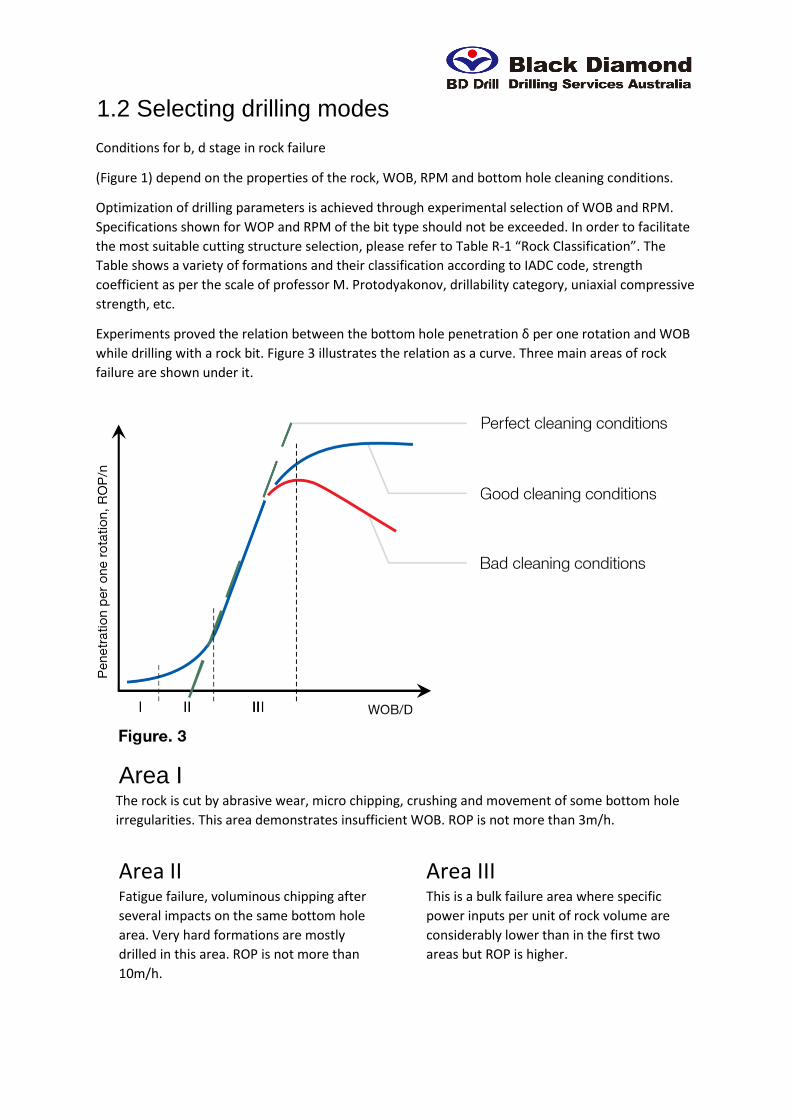
Experiments proved the relation between the bottom hole penetration δ per one rotation and WOB
while drilling with a rock bit. Figure 3 illustrates the relation as a curve. Three main areas of rock
failure are shown under it.
Area I The rock is cut by abrasive wear, micro chipping, crushing and movement of some bottom hole
irregularities. This area demonstrates insufficient WOB. ROP is not more than 3m/h.
Area II
Fatigue failure, voluminous chipping after
several impacts on the same bottom hole
area. Very hard formations are mostly
drilled in this area. ROP is not more than
10m/h.
Area III
This is a bulk failure area where specific
power inputs per unit of rock volume are
considerably lower than in the first two
areas but ROP is higher.

When RPM is modified, the quantity of insert impacts against the bottom hole per time unit
changes. The penetration per one rotation (δ) can be expressed by ROP:
ROP = n •
Figure 4 shows how bit penetration per one
rotation (δ) and ROP depend on RPM. With
increased RPM in n < n1 section, the values of ROP
and δ increase. With increased RPM in n1≤n≤n2
section, δ decreases but ROP keeps growing. With
further increase in RPM in n>n3 section, the values
of δ and ROP decrease considerably. ROP
decreases after the point n3 due to:
• Reduced insert-rock interaction time;
• Decreased impact energy applied to an insert;
• Increased dynamic resistance of the rock drilled
due to its plastic properties with little bit
penetration per one rotation;
• Increased drilling rod vibrations;
• Changed mode of the air flow at the bottom
hole;
• Increased power consumption.
Continuous air flushing while drilling ensures
bottom hole clearing, the bit cooling and
contributes to the efficient penetration into rock.
An optimum ratio of the value of a bit penetration
per one rotation δ and ROP on Figure 4
corresponds to bit RPM n opt. A further increase of
RPM will result in erosion of the bit cutting
structure and bearing with little further increase of
ROP.
1.3 Practical use of test results
The maximum ROP is determined
experimentally for each bit type and size in
given mining and geological applications.
Therefore an optimum ratio of WOP and RPM
is theoretically achieved when the depth of
cut is about 80% of insert protrusion. 20%
remain for efficient cuttings removal. In
practice the recommended drilling
parameters for a particular bit type and size
shall be determined using Tables K-1 and K-2.
The target is to determine the maximum ROP
with the given WOP and RPM. The maximum
ROP value will correspond to the optimal
WOP and RPM values.
Excessive WOB which makes depth of cut
more than 80% results in the following:
1.Cuttings will not be completely removed
from rock cutting area;
2.Rock is milled repeatedly;
3.ROP decreases;
4.Bit cutting structure and bearing wear
intensively;
5.Load on the drilling rig rotary head
increases.
Section 2. Air Circulation System
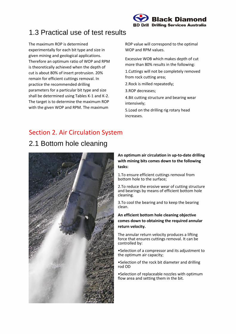
2.1 Bottom hole cleaning
An optimum air circulation in up-to-date drilling
with mining bits comes down to the following
tasks:
1.To ensure efficient cuttings removal from bottom hole to the surface;
2.To reduce the erosive wear of cutting structure and bearings by means of efficient bottom hole cleaning.
3.To cool the bearing and to keep the bearing clean.
An efficient bottom hole cleaning objective
comes down to obtaining the required annular
return velocity.
The annular return velocity produces a lifting force that ensures cuttings removal. It can be controlled by:
•Selection of a compressor and its adjustment to the optimum air capacity;
•Selection of the rock bit diameter and drilling rod OD
•Selection of replaceable nozzles with optimum flow area and setting them in the bit.

Actual compressor capacity changes depending on the throttle flap position, wear of the screw pair and the compressor body, altitude above the sea level and manifold leakage. Factors that affect the value of the annular velocity for cuttings removal:
• Correlation between the bit diameter and the drill pipe OD;
• Drilling rod gauge loss as a result of the wear;
• Rock specific strength;• Sizes and shapes of cuttings;
• Water in the hole.
They can be expressed by the following formula:
Q = 47 • V • (D2b – D2
p)
Where Q is – air flow, m3/min;
V – is desired air velocity, m/sec;
It should be noted that:
• The air velocity for drilling light weight rock is to be more than 25 m/sec;
• The air velocity for drilling heavy weight rock is to be more than 35 m/sec;
• The air velocity for drilling heavy weight rock with high water content is to be more than 50 m/sec; Db — is Bit diameter, m;
Dp — is Pipe Diameter, m;

2.2 Required drilling rig compressor capacity
The required value of compressor capacity versus air velocity, rock bit diameter and drill rod
diameter is shown in Table R-2.
The above calculation gives a preliminary estimate of required compressor capacity. The final data
can be obtained only after a test drilling.

2.3 Nozzles selection
Optimum combination of drilling equipment on a drilling rig (bit diameter, drilling rod diameter,
actual compressor capacity) for given mining and geological applications makes it possible to achieve
the required annular velocity and satisfactory bottom hole cleaning and cuttings removal. The better
are the bottom hole cleaning and cuttings removal, the less is the erosive wear of the cutting
structure and the bearing at maximum ROP. However, it is very important to realize that air
circulation system is to ensure not only the required annular return velocity but to provide
conditions for the best cooling and cleaning the bearing. This problem is solved solely by the choice
of bit nozzles diameter, because only nozzles selection makes it possible to gain an air pressure drop
in a bit which is required for successful drilling.
Recommended air pressure in a bit is determined in each case experimentally by making
measurements with a special pressure gauge. The long-term experience in drilling blast holes reveals
that the air pressure in a bit has to be within the range of not less than 0.20 – 0.22 MPa (29.7 – 32.6
psi) and has to match physical and mechanical properties of formations and drilling applications.
Failure to observe the recommended values of air pressure in a bit will inevitably result in premature
bearing failure.
2.4 Nozzles replacement
Nozzles are fixed with a nail(circlip). The circlip is installed in a circlip groove in the leg and fills in the
ring groove made in the nozzle recess of the leg and in the nozzle. Such method is the most reliable
and facilitates nozzles replacement. Nozzles replacement procedure:

2.5 On-site measurement of compressor capacity
Values obtained with this method are true only for
Black Diamond bits when their air passages are free
from cuttings. It is recommended to measure
compressor capacity in the following order:
1. Determine bit type and size and its condition.
Only new bits or bits in good condition can be used.
2. Determine the flow area of the nozzles. Be sure
that all three nozzles are the same.
3. When the compressor is switched on, check the
air flow under the cones to make sure that all air
passages are empty. The compressor should run
with a nominal working temperature and with
water supply switched off.
4. Determine air temperature with the tools in the
operator’s booth.
5. Install a pressure gauge into one of the nozzles
and measure the pressure.
6. Basing on the corresponding bit and nozzle
diameter find compressor capacity in the table.
The subject method makes it possible to measure an actual drilling rig compressor capacity on-site
taking into account its wear, air circulation system leakage and other factors.
Table R-3

Section 3. Guidelines to rock bit operation Our recommendations will allow you to obtain good bit performance
Before drilling
3.1 Inspect the thread condition of the drill pipe drive rod. If the thread condition is unsatisfactory, the drive rod should be replaced.
3.2 Inspect the drilling rod condition. Do not use curved rods or a worn thread.
3.3 Inspect the bushings condition. Do not use worn bushings.
3.4 Inspect compressor based on the pressure gauge reading on the outlet as compared to its specification data. Adjust the flap position if necessary.
3.5 Inspect the air ducts and hoses for leakage. Fix the leakage found in the system.
3.6 Inspect the control equipment. Replace faulty equipment.
3.7 Inspect hoisting jacks. Do not allow loosing the drilling rig horizontal position while drilling
3.8 Inspect the bit condition and completeness, reliability of the fixture and state of the relieve valve, availability and size of nozzles, thread connection
3.9 Do not make unauthorized changes to the bit design by means of cutting or welding additional parts or removing relieve valve and nozzles.
3.10 Flush the drilling assembly with air before screwing on the bit
3.11 Avoid impacts or shifts when screwing on the bit
3.12 Set the air pressure in the bit not less than 0.2 MPa by means of selecting the nozzles.
While drilling
3.13 Fill in the Bit Record Sheet for each bit.
3.14 Break in a new bit for 15 minutes with the drilling rod rotation at 30 RPM and WOB of 10% of the upper limit recommended in the bit specification. Break in a new bit in a new hole (except for the first row holes) with the compressor on.
3.15 Smoothly apply the operation parameters recommended in the bit specification. Do not exceed the WOB and RPM indicated in the specification.
3.15.1 If with sequential increase in WOB the ROP does not increase or decreases, then the WOB shall be reduced to the earlier registered level at which the maximum ROP was obtained.
3.15.2 If the drilling rod starts vibrating, then the bit RPM or WOB shall be reduced to the level at which the vibration stops.
3.16 Optimum drilling parameters shall be determined only by experiment. The most critical factor is the maximum ROP
3.17 Drill only with the compressor switched on.
3.18 Do not apply weight on bit when it does not rotate.
3.19 Do not drill when the bit cones are balled up and do not rotate.
3.20 Do not drill when the bit air passages are blocked.
3.21 Do not complete an old hole with a new bit. It can result in shirttail and hill row inserts cracking and cones jamming.
3.22 Carry out tripping and hole conditioning only with the drilling assembly rotating and the compressor on.
3.23 Do not use new or test bits to clean out collapsed holes. Always apply a used bit for this purpose.
3.24 Emergency stop and leaving a bit at the bottom hole with the compressor off may result in plugged bearing and cones jamming. To prevent its early failure, conduct the following control measures:
3.24.1 Lift the bit above the bottom hole by 1.5-2 meters with no rotation. Turn on the compressor and flush the bit. While doing so, control the pressure increase in the drilling rig air line with a pressure gauge.
3.24.2 Pull the bit out of the hole, clean the bit, check cones rotations manually, turn the compressor on, and visually check flushing air through the cones.
3.24.3 You can continue drilling with the bit if the bit examination results are satisfactory for the drilling rig operator.
3.24.4 If the bit examination results are not satisfactory for the drilling rig operator, then the bit shall be removed for repair.
After drilling
3.27 Used bits intended for repair and drilling in the wells or for cleaning of choked wells shall be flushed and cleaned from mud, their bearing and thread shall be lubricated. It is not recommended to use new bits in repair operations.
3.28 Dull bits intended for scrapping shall be:
3.28.1 Examined by the drilling rig operator and registered in the bit registry.
3.28.2 Disassembled in order to have a stock of replaceable parts, i.e. relieve valves and nozzles on site.
3.29 Drilling report is forwarded to the engineer for registering the bits and analysing Bit Performance Statistics
3.30 A rate of bit performance is determined based on “Bit Performance Statistics” for a specific mine by an average performance of not less than 50 bits of the similar size and type and designation with a Report issued.
3.31 A report on dull bit performance statistics including meters drilled, hours and ROP is recommended to be delivered to the manufacturer.

Section 4. Dull bit analysis
a.Broken teeth (BT)
Examination:
Teeth break flush to cone body.
Causes
• Too high RPM.
• Broken, disintegrated formation while
drilling or spudding a well.
• Improper bit.
• Alteration of formations including very hard
ones.
Recommendation
• Reduce the RPM.
• Drill sections interbedded with very hard
formations with reduced WOB and RPM.
• Select a bit with the cutting structure
features fitting the drilling conditions.
b.Chipped teeth (CT)
Examination
Chipped tungsten carbide inserts.
Causes
• Excessive WOB.
• Broken, disintegrated formation while drilling
or spudding a well.
• Wrong TCI grade.
• Cone interference.
Recommendation
• Revise the drilling applications and WOB.
• Reduce WOB and gradually reduce RPM.
• Select a bit with more wear resistant TCI.
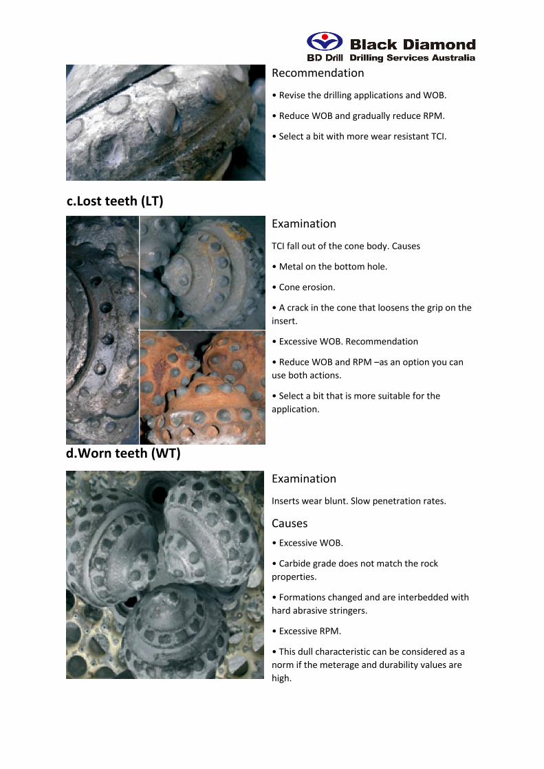
c.Lost teeth (LT)
Examination
TCI fall out of the cone body. Causes
• Metal on the bottom hole.
• Cone erosion.
• A crack in the cone that loosens the grip on the
insert.
• Excessive WOB. Recommendation
• Reduce WOB and RPM –as an option you can
use both actions.
• Select a bit that is more suitable for the
application.
d.Worn teeth (WT)
Examination
Inserts wear blunt. Slow penetration rates.
Causes
• Excessive WOB.
• Carbide grade does not match the rock
properties.
• Formations changed and are interbedded with
hard abrasive stringers.
• Excessive RPM.
• This dull characteristic can be considered as a
norm if the meterage and durability values are
high.
Recommendation
• Reduce WOB and RPM – as an option you can use
both actions.
• Select a bit with another shape of inserts and with
a more wear resistant carbide grade.
• Select a bit that is more suitable for the
application.
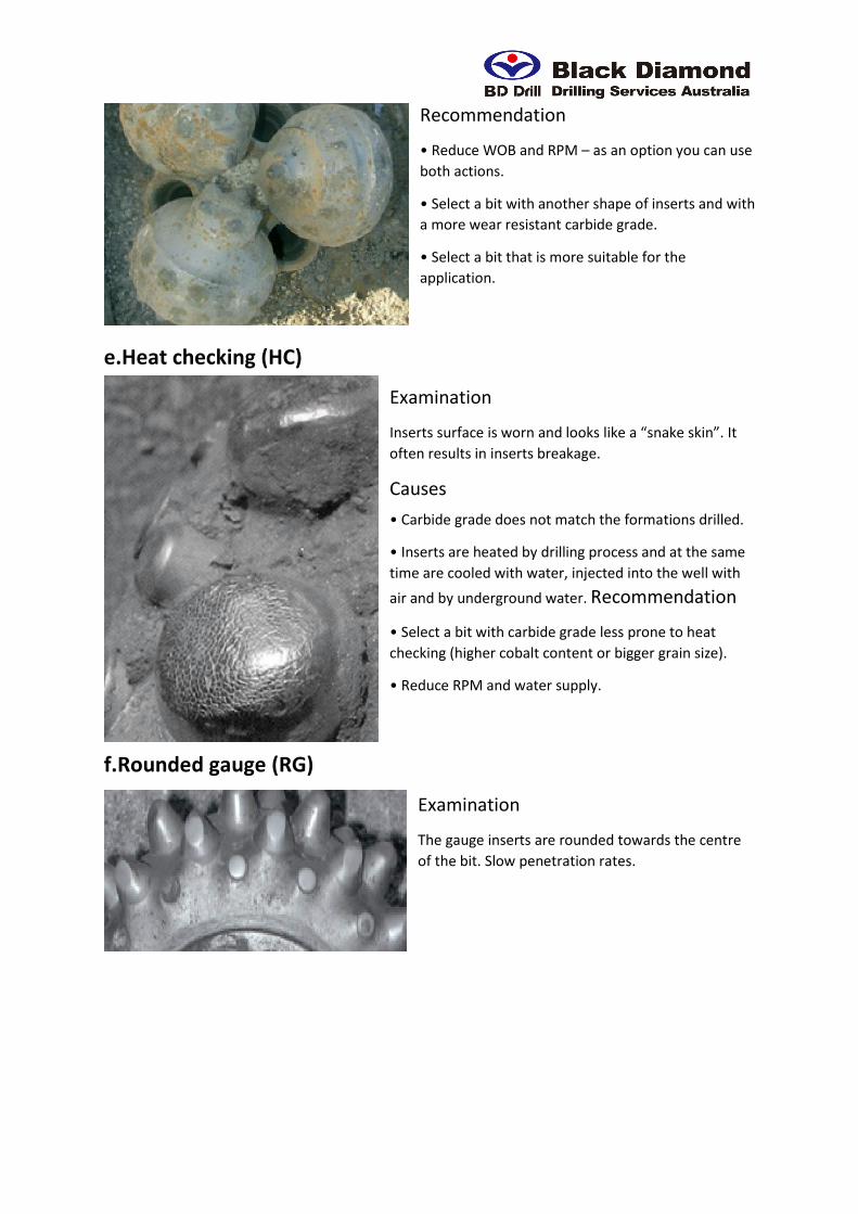
e.Heat checking (HC)
Examination
Inserts surface is worn and looks like a “snake skin”. It
often results in inserts breakage.
Causes
• Carbide grade does not match the formations drilled.
• Inserts are heated by drilling process and at the same
time are cooled with water, injected into the well with
air and by underground water. Recommendation
• Select a bit with carbide grade less prone to heat
checking (higher cobalt content or bigger grain size).
• Reduce RPM and water supply.
f.Rounded gauge (RG)
Examination
The gauge inserts are rounded towards the centre
of the bit. Slow penetration rates.
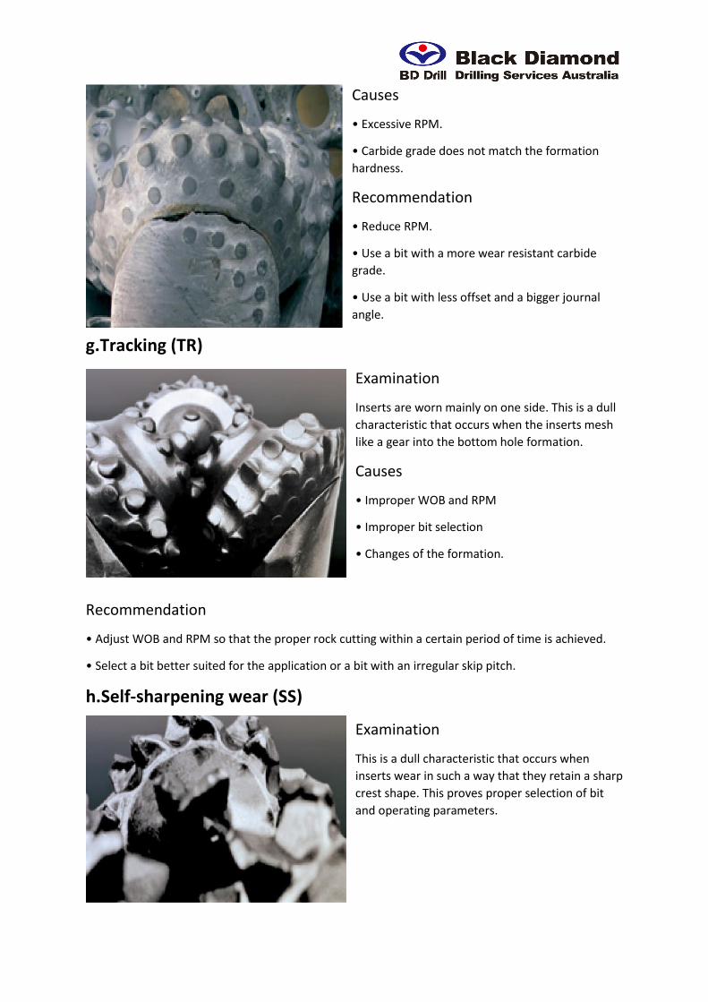
Causes
• Excessive RPM.
• Carbide grade does not match the formation
hardness.
Recommendation
• Reduce RPM.
• Use a bit with a more wear resistant carbide
grade.
• Use a bit with less offset and a bigger journal
angle.
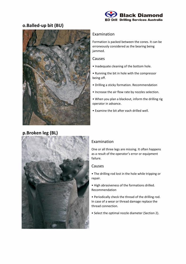
g.Tracking (TR)
Examination
Inserts are worn mainly on one side. This is a dull
characteristic that occurs when the inserts mesh
like a gear into the bottom hole formation.
Causes
• Improper WOB and RPM
• Improper bit selection
• Changes of the formation.
Recommendation
• Adjust WOB and RPM so that the proper rock cutting within a certain period of time is achieved.
• Select a bit better suited for the application or a bit with an irregular skip pitch.
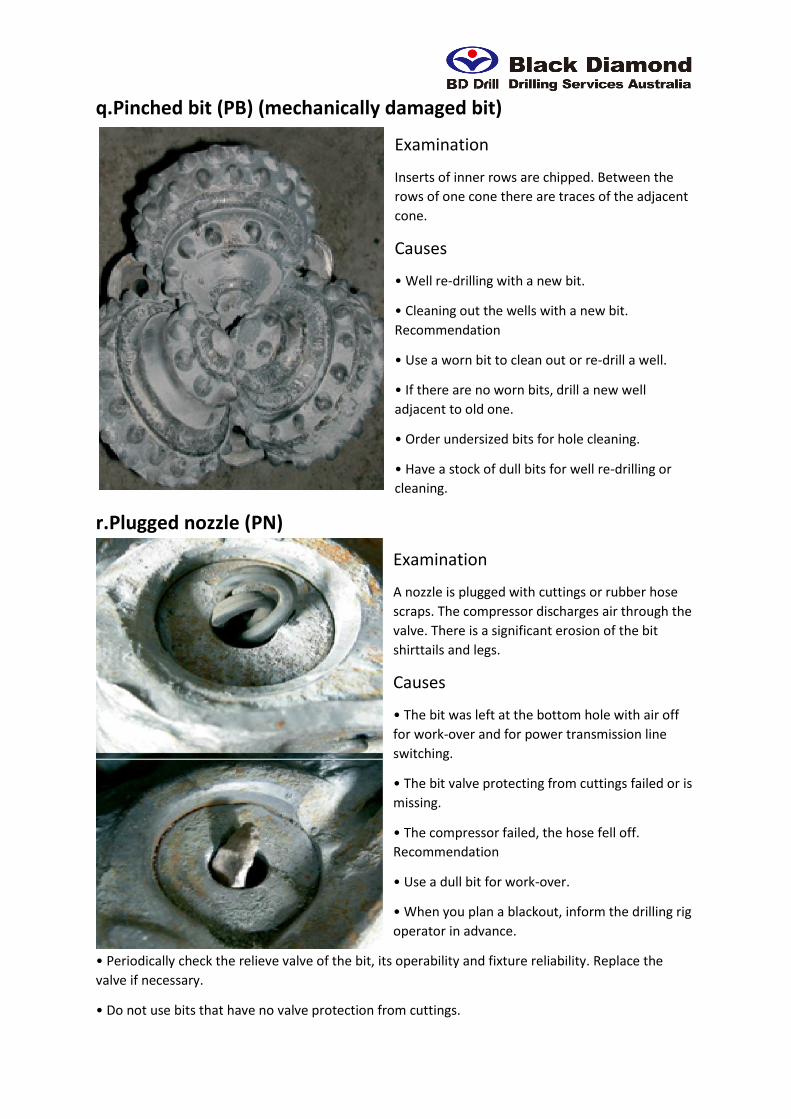
h.Self-sharpening wear (SS)
Examination
This is a dull characteristic that occurs when
inserts wear in such a way that they retain a sharp
crest shape. This proves proper selection of bit
and operating parameters.

i.Erosion (ER)
Examination
Cone steel erodes away round the inserts and
results in loss of inserts. Also, excessive leg
erosion can result in loss of inserts on the legs
and in shirttail wear, air passage opening and loss
of cone.
Causes
• High abrasiveness of the formations drilled.
• Inadequate air volume flowing through the
nozzles.
• Wet (from either ground water or excessive
water injection) sticky and abrasive formations.
Recommendation
• Select WOB and RPM to achieve maximum ROP.
• Inspect air supply system for leakage.
• If water dust control is used, reduce water
supply. Make sure that the nozzles are not
plugged.
• Inspect cuttings removal efficiency.
• Increase nozzle size to reduce air pressure.
j.Cracked cone (CC)
Examination
The cone cracks either axially or
circumferentially.
Causes
• Cone steel fatigue.
• Cone interference making the cone heat and
generate cracks.
• Excessive WOB.
• Dropped drilling rod.
Recommendation
• This dull characteristics can be allowed if the bit is run for a long time. • Reduce WOB. • Review
the drilling applications and make sure that the bit drills the bottom hole smoothly with no impacts.
• Monitor and control the wear of drilling rod threaded joints.

k.Lost cone(LC)
Examination
Cones are left at the bottom hole.
Causes
• The bit overdrilled the bottom hole.
• Bit shock problem.
• Bearing failure (all rollers and balls fell out).
Recommendation
• Observe instructions in the bit manual.
• Monitor and control wear of the drilling rod
threaded joints.
l.Cone interference (CI)
Examination
Bearing wear results in the teeth (inserts) of one
cone interfering with another cone. It often
results in intermittent cone jamming and inserts
deterioration and radial cone breakage.
Causes
• Excessive WOB resulting in exaggerated
bending moment of journals.
• Plugged air passages, as a result bearings are
not properly cooled.
• Insufficient air volume supplied to the bearing.
• Running a bit in an under-gauge well.
• Rollers and balls fall out of one cone.
Recommendation
• Reduce WOB.
• Inspect drilling rods condition, their wear and
deviation.
• Inspect drilling assembly bushings for wear.
• Check the back pressure valve availability as
well as nozzles availability and proper selection.

m.Cone dragged (CD)
Examination
All three cones are jammed. The cones have
typical tracks (flats) caused by inserts sliding at
the bottom hole.
Causes
• Drilling with an air compressor switched off or
failed.
• Air supply stopped or is insufficient due to air
hose tear or air leakage in the circulation system.
• A foreign object jammed between the cones.
• Bit balling up. Recommendation
• Repair and adjust the compressor.
• Eliminate air leakage.
• Follow the instructions in the bit manual.
n.Cored bit (CR) (Loss of cone noses)
Examination
Nose parts of the cones are missing or worn.
Causes
• Excessive WOB resulting in the cone body
coming in contact and hitting against the bottom
hole.
• Inadequate hole cleaning causing cone erosion.
• Cone noses of the bits with central nozzle wear
badly while drilling abrasive formations due to
sand blasting effect resulting in lost inserts and
worn noses.
• Junk on the bottom hole.
Recommendation
• Reduce WOB.
• Select inserts projection, shape, diameter and
quantity so that the cone body would not contact
or hit against the bottom hole.
• Measure the actual compressor capacity, drilling rod diameter and check the nozzles selection.
• Replace the bit with a central nozzle by a bit with side nozzles only.
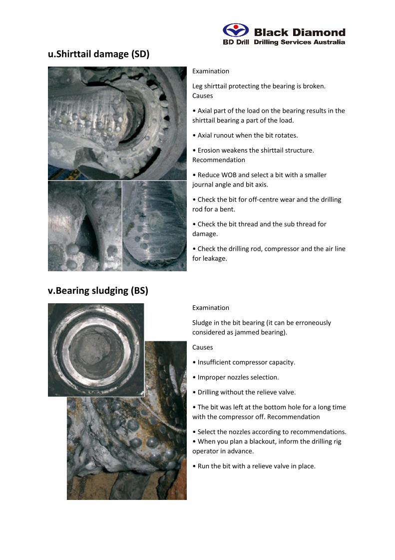
o.Balled-up bit (BU)
Examination
Formation is packed between the cones. It can be
erroneously considered as the bearing being
jammed.
Causes
• Inadequate cleaning of the bottom hole.
• Running the bit in hole with the compressor
being off.
• Drilling a sticky formation. Recommendation
• Increase the air flow rate by nozzles selection.
• When you plan a blackout, inform the drilling rig
operator in advance.
• Examine the bit after each drilled well.
p.Broken leg (BL)
Examination
One or all three legs are missing. It often happens
as a result of the operator’s error or equipment
failure.
Causes
• The drilling rod lost in the hole while tripping or
repair.
• High abrasiveness of the formations drilled.
Recommendation
• Periodically check the thread of the drilling rod.
In case of a wear or thread damage replace the
thread connection.
• Select the optimal nozzle diameter (Section 2).
q.Pinched bit (PB) (mechanically damaged bit)
Examination
Inserts of inner rows are chipped. Between the
rows of one cone there are traces of the adjacent
cone.
Causes
• Well re-drilling with a new bit.
• Cleaning out the wells with a new bit.
Recommendation
• Use a worn bit to clean out or re-drill a well.
• If there are no worn bits, drill a new well
adjacent to old one.
• Order undersized bits for hole cleaning.
• Have a stock of dull bits for well re-drilling or
cleaning.
r.Plugged nozzle (PN)
Examination
A nozzle is plugged with cuttings or rubber hose
scraps. The compressor discharges air through the
valve. There is a significant erosion of the bit
shirttails and legs.
Causes
• The bit was left at the bottom hole with air off
for work-over and for power transmission line
switching.
• The bit valve protecting from cuttings failed or is
missing.
• The compressor failed, the hose fell off.
Recommendation
• Use a dull bit for work-over.
• When you plan a blackout, inform the drilling rig
operator in advance.
• Periodically check the relieve valve of the bit, its operability and fixture reliability. Replace the
valve if necessary.
• Do not use bits that have no valve protection from cuttings.

• Adjust the compressor, eliminate air leakage,
clean the bit from cuttings (nozzles and air
passages in the legs).
• Flush the drilling rod with air before screwing
the bit on.
s.Lost nozzle (LN)
Examination
A lost nozzle usually results in a sharp pressure
drop and requires an immediate bit pulling out.
Causes
• Breaking the rules of nozzle installation.
• Mechanical damage of nozzles or their retention
system.
• Nozzles or their fixture erosion.
• Bit balling up. Recommendation
• Examine the bit after each drilled well.
t.Off-center wear (OC)
Examination
Excessive wear of one or two legs (legs, shirttails);
of one or two cones (gauge and hill rows), along
with bearings failure; cones jammed and balls and
rollers lost.
Causes
• The drilling rod is bent which results in off-centre
bit rotation (radial runout).
• Hoisting jack has failed.
• The bit is screwed to the above bit sub with a
warp, the bit thread is damaged.
• The thread of the sub (box) is not cut properly,
the thrust face of the sub does not thrust against
that of the bit. Recommendation
• Check the drilling rod rotation for eccentricity.
• Check the bit for damaged thread. • Check and replace the above-bit sub if its thread is damaged.
u.Shirttail damage (SD)
Examination
Leg shirttail protecting the bearing is broken.
Causes
• Axial part of the load on the bearing results in the
shirttail bearing a part of the load.
• Axial runout when the bit rotates.
• Erosion weakens the shirttail structure.
Recommendation
• Reduce WOB and select a bit with a smaller
journal angle and bit axis.
• Check the bit for off-centre wear and the drilling
rod for a bent.
• Check the bit thread and the sub thread for
damage.
• Check the drilling rod, compressor and the air line
for leakage.
v.Bearing sludging (BS)
Examination
Sludge in the bit bearing (it can be erroneously
considered as jammed bearing).
Causes
• Insufficient compressor capacity.
• Improper nozzles selection.
• Drilling without the relieve valve.
• The bit was left at the bottom hole for a long time
with the compressor off. Recommendation
• Select the nozzles according to recommendations.
• When you plan a blackout, inform the drilling rig
operator in advance.
• Run the bit with a relieve valve in place.

Section 5. Selection of efficient bit designs It is important to select efficient bit designs for specific mining and geological applications to ensure
the best performance (reduced expenses for drilling equipment and drilling operations, increased
drilling rigs productivity, reduced time for blast blocks preparation). Our specialists give all
recommendations on the optimum bit types and sizes selection and analyse the efficiency of bit
runs. Efficient bit selection at each mining company is made based on a complex assessment of:
• Mining, geological and technological drilling applications
• Rock bit statistics
• Dull bit analysis
• Cutting structure and design features
• Technical and economic indices of bits performance based on test results. If necessary, we can
design and manufacture rock bits based on our customer’s specific requirements.
5.1 Mining and geological applications analysis
A critical factor that affects bit performance is the mining and geological applications analysis. Rock
properties, namely uniaxial compression strength δ, average formation hardness factor F as per
professor Protodyakonov’s scale, alteration, stringers, attitude of beds, water cut, abrasiveness,
broken formations, etc. determine rock bit specification and design features. Since geology may alter
with a mine deepening and widening, it is important to consider the drilling volume as per “Long
Term Drilling Operation Plan”.
5.2 Technological applications analysis
Intensive mining complex development is directly related to technical re-equipment and
replacement of drilling rigs. Such technical characteristics of drilling rigs as drilling performance,
drilling assembly, connecting thread, compressor capacity should match the design features of bits.
It is obvious, that it is impossible to achieve a considerable economic effect in drilling using the
state-of-the-art bits with old and worn drilling rig. At the same time, it is well possible to reduce
drilling expenses by selection of bits efficiency of which would match actual drilling rig technical
parameters.
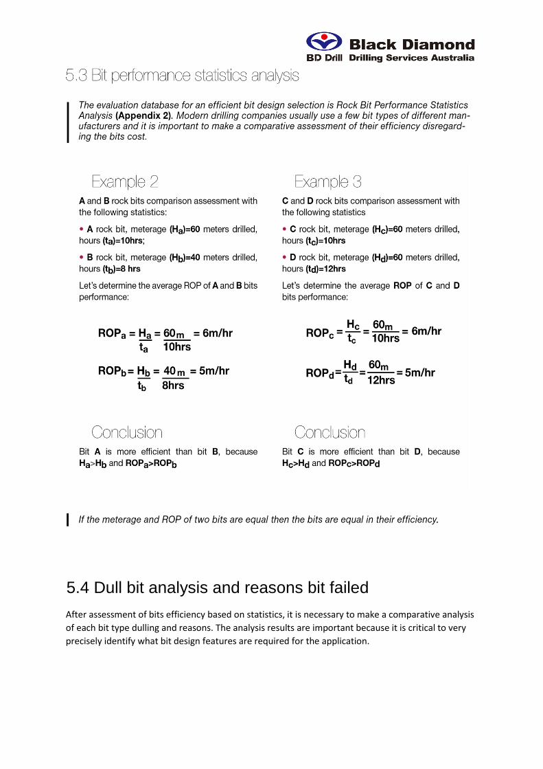
5.4 Dull bit analysis and reasons bit failed
After assessment of bits efficiency based on statistics, it is necessary to make a comparative analysis
of each bit type dulling and reasons. The analysis results are important because it is critical to very
precisely identify what bit design features are required for the application.

5.5 Bit cutting structure and bearing design features
analysis
As a rule, to select bits for optimization of their design features, drilling specialists in mining
companies use bits identification method based on the data provided by manufacturers. It is a list of
products at websites and in catalogues with bits specifications. The information contains alphabetic
characters as per GOST 20692-2003 and the designation as per IADC code.
5.6 Analysis of technical and economic indices of bits
performance based on field test results
A bit design efficiency is determined based on comparative test results in equal mining and
geological conditions. An efficient bit design should be considered the one that ensures the
minimum value of operational expenses for drilling one running meter of a hole which is determined
by the formula: