ROTARY DRILLING
In the rotary method, the hole is drilled by a rotating bit to which a downward force is applied. The bit is fastened to, and rotated by, a drill string, composed of high quality drill pipe and drill collars, with new sections or joints being added as drilling progresses.
The cuttings are lifted from the hole by the drilling fluid which continuously circulated down the inside of the drill string through water courses or nozzles in the bit, and upward in annular space between the drill pipe and bore hole.
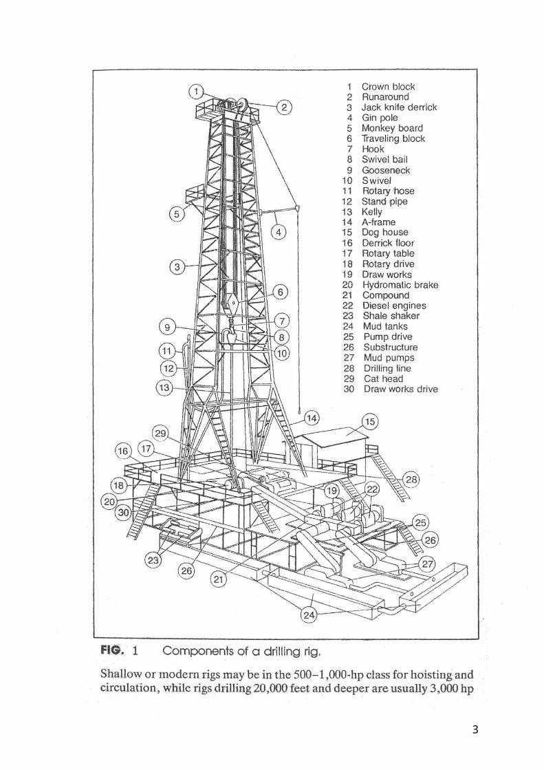
At the surface, the returning fluid (mud) is diverted through shale shakers, desilters, desanders and series of tanks or pits which treat the fluid. In the last of these pits the mud is picked up by the pump suction and repeats the cycle. Figure 1 shows the basic components of a rotary drilling rig.
1
2
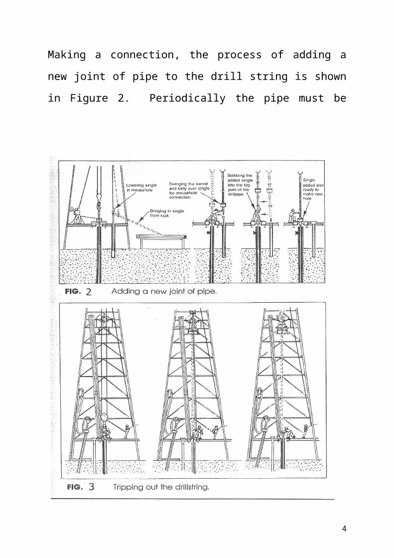
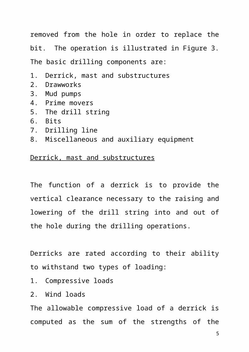
Making a connection, the process of adding a new joint of pipe to the drill string is shown in Figure 2. Periodically the pipe must be removed from the hole in order to replace the bit. The operation is illustrated in Figure 3.
3
The basic drilling components are:1. Derrick, mast and substructures2. Drawworks3. Mud pumps4. Prime movers5. The drill string6. Bits7. Drilling line8. Miscellaneous and auxiliary equipment
Derrick, mast and substructures
The function of a derrick is to provide the vertical clearance necessary to the raising and lowering of the drill string into and out of the hole during the drilling operations.
Derricks are rated according to their ability to withstand two types of loading:1. Compressive loads2. Wind loadsThe allowable compressive load of a derrick is computed as the sum of the strengths of the four legs. Derricks with load capacities from approximately 86,000 to 1,400,000 lb, depending on steel grade and leg size are available.Allowable wind loads for API derricks are specified in two ways, with or without pipe setback.
4
With pipe setback, the wind may be blowing perpendicular to it, which is essentially a pipe wall. This is the worst possible condition.
Wind loads are calculated by the formula:P = 0.004V2
where P = wind load, lb/ft2
V = wind velocity, mph
Calculation of Derrick Loads
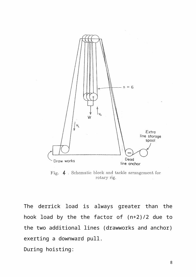
The block and tackle arrangement for a rotary rig is shown in Figure 4. Assuming that the system is frictionless, the following relationship are apparent:
where Fd = total compressive load on the derickn = number of lines through the
travelling block (those supporting W).W = hook load
5
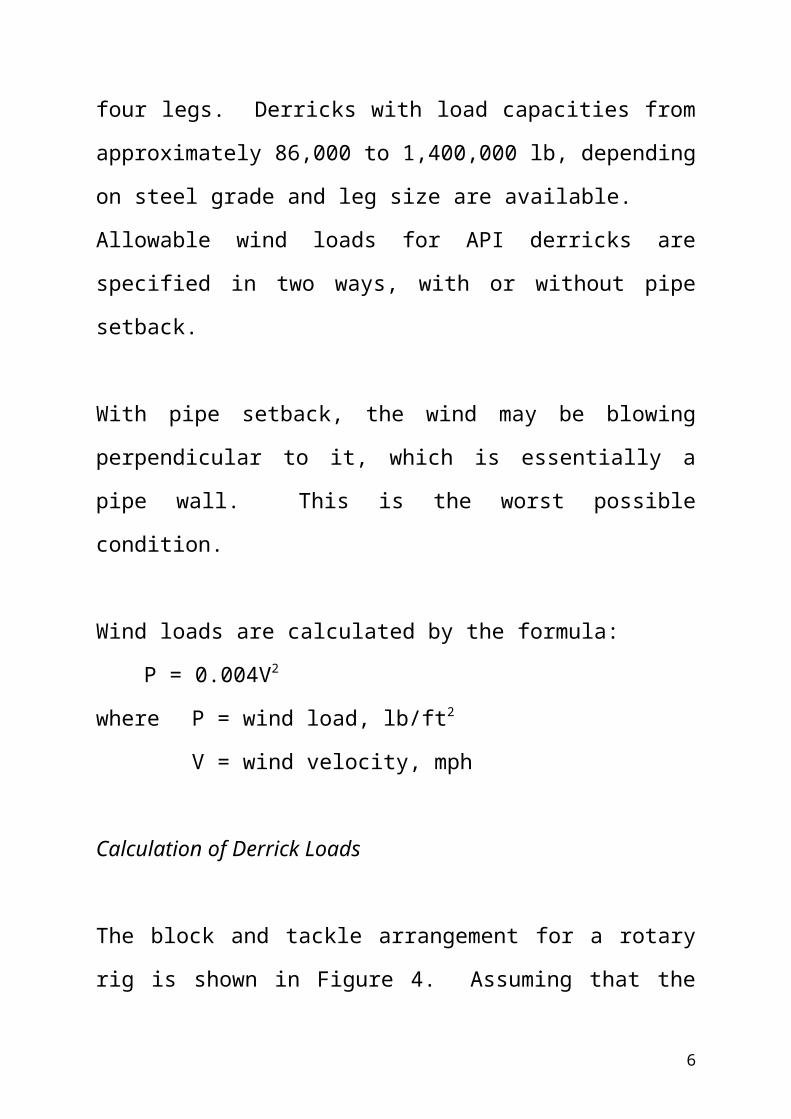
The derrick load is always greater than the hook load by the the factor of (n+2)/2 due to the two additional lines (drawworks and anchor) exerting a downward pull.During hoisting:
vL = nvA
6

where vL = velocity of line being spooled (or unspooled) at the drawworks during hoisting.
vA = hook velocity
Drawworks (hoist)
The drawworks or hoist is the key piece of equipment on a rotary rig. The functions of the drawworks are:
1. It is the control centre from which the driller operates the rig. It contains the clutches, chains, sprockets, engine throttles and other controls wich enable the rig pwer to be diverted to the particular operation at hand.
2. It houses the drum which spools the drilling line during hoisting operations and allows feed-off during drilling.
Drawworks are commonly designated by a horsepower and depth rating.
where W = Hook load, lb
7
vh = hoisting velocity of travelling block, ft/min33,000 = ft.lb/min per horsepowere = Hook to drawworks efficiency
Hook to drawworks efficiencies are commonly between 80 to 90%, depending on the number of lines in use.
Mud Pumps
the function of the mud pumps is to circulate the drilling fluid at the desired pressure and volume. The pump normally used is the reciprocating piston, double acting, duplex type. The term “double acting” denotes that each side of the piston does work, while “duplex” refers to the number of pistons (two).The superiority of the piston type pump for drilling service is due to the following features:1. Ability to handle fluids containing high percentages
of solids, many of which are abrasive.2. Valve clearance will allow passage of large solid
particles (typically lost circulation materials) without damage.
3. Ease and simplicity of operation and maintenance. Liners, pistons and valves may be replaced in the field by the rig crew.
8
4. Wide range of volume and pressure available by using different liner and piston sizes.
Prime Movers
The bulk of rig power is consumed by two operations:1. Circulation of the drilling fluid2. Hoisting
Fortunately these requirements do not occur at the same time and the same engine perform both jobs.The prime movers used are the steam engines, electric motors and internal combustion engines. The most commonly used is the internal combustion engines such as the automotive type (multicylinder, light flywheel) diesel and gas engines capable of rapid acceleration.
The Drill String
The rotary drill string includes the components as in Figure 5.
9
Fig. 5: Schematic diagram of drill string components and bit. Bit load is furnished by heavy walled large-diameter drill collars.
Rotary bits
The bit is the part that drill the hole. Basically there are three types of drill bits, these are the drag type, rolling cutter type and the diamond bit. The most common is the rolling cutter type. The diamond bit is commonly used in hard formations.
Drilling line
10
The rotary drilling line afford a means of handling the load suspended from the hook during all drilling operations.
The maximum load occurs when running casing, although fishing operations frequently require line pulls in excess of the drill string weight.
Travelling Block, Hook and Swivel
The travelling block is the travelling pulley assembly that connects the drilling line to the hook and swivel. The swivel must suspend the drill string and allow rotation at the same time.
Blowout Preventer (BOP)
The main function of a blowout preventer is to furnish a means of closing off the annular space between the drill pipe and casing.
It is not always possible to predict the exact manitude of pressures which will be encountered in the drilling of a well. Consequently it is not uncommon to encounter pressure greater than those imposed by the drilling
11
fluid, with the result that formation fluids flow into the bore hole and eventually to the surface.
This effect is called a blowout, and is one of the most feared and expensive accidents which can occur in well drilling.Most blowout preventers are either hydraulically or pneumaticaly operated, with manual operation available as a safetry precaution.
12