A MAJOR PROJECT REPORT
ON
ROBOTIC ARM WITH WIRELESS COMMUNICATION
PRESENTED BY:A.APOORVA(11c81AO407)K.LAVANYA(11c81a0457)G.JOSHNA DEVI(11c81a0447)K.SRAVAN KUMAR(11c81a0472)
UNDER THE GUIDENCE OF:Mrs.D.SAILAJA M.TECH.(Ph.D).,
ASSOCIATE PROFESSOR,HEAD OF THE DEPARTMENT.

TABLE OF CONTENTS
1) INTRODUCTION
2) SYSTEM DESIGN
3) ELECTRONIC ASPECT
4) MECHANICAL ASPECT
5) PCB DESIGNING
6) SALIENT FEATURES
7) COMPONENTS USED
8) CONCLUSION
9) REFERENCE

ABSTRACTNow a day’s every system is automated in order to face new challenges in the
present day situation. Automated systems have less manual operations, flexibility,
reliability and accurate. Due to this demand every field prefers automated control
systems. Especially in the field of mechanics automated systems are doing good
performance.
In this system, the robot is fitted with total of five stepper motors. A
micro controller is used to control all operations. It moves the arm in all directions and
it is attached with a gripper to hold and move the objects. This vehicle is operated with
battery power. With this system we can complete our work with the robot help.
A 12V battery is provided to power the robot to perform all functions. These are
very useful for carrying files in offices, or any other material which human cannot
handle.

NEED OF PROJECT
Extensive applications in hazardous conditions
Replaced massive human work force
Areas of application:
Medical science
Surgeries
Defense
Artificial intelligence

NEED OF PROJECT
We extended applications of robotics
To use in industries for purpose of picking and
placing objects
To use it in case of wars
To pull out casualties from war front
Autonomous robot that could reach far and wide
This gave birth to surveillance pick and place robot
Defined as mechanical design capable of
performing tasks in human like manner
Requires expertise and programming
Sub systems
Pick and place robot has an arm
GENERAL DESIGN

STEPS OF IMPLEMENTATION
Designer needs to be fully aware of
system requirements
Process begins with hardware design
o Mechanical design assembly
o Stable structure capable of bearing
load

IMPLEMENTATION
Electronic circuit is designed in ‘eagle’(Easily
Applicable Graphical Layout Editor(EAGLE))
o Microcontroller is chosen
o Circuit designed around it
Implementation of code
o Code is compiled using ‘KEIL’ compiler
Code tested on simulators
o Adjustments made on code
o Removal of errors

IMPLEMENTATION
PCB for the main board is etched
o Components are mounted
o Soldering is done
Testing of entire system
o Put through tasks
o Performance parameters are observed
o System checked for faults

BLOCK DIAGRAMTRANSMITTER

RECEIVER

MAIN CIRCUIT DIAGRAM

FEATURES OF THE MECHANICAL DESIN:
Two motors for running the wheels of the robot.
Two motors for the movement of robotic arm.
Movement up and down
Movement of jaw open and close
Wireless Camera on top of the assembly
Rectangular metal box as the base
A Belt around wheels, in order to save on the usage of hardware.

PRINTED CIRCUIT BOARD(PCB)
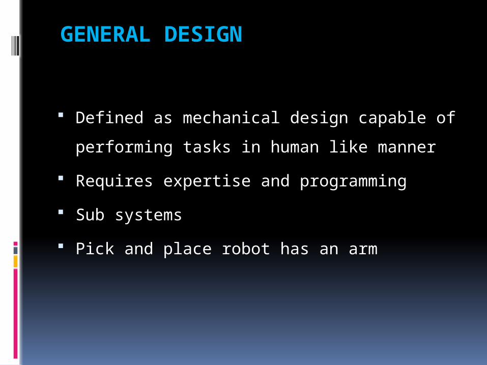
APPLICATIONS:
Military applications Surveillance device
To pull out casualties
Can be used to transport objects just
on a click of a button
Industrial applications Loading of objects
Serving security purposes
Surveillance
Reaching places out of human reach

ADVANTAGES:
Wireless
Simple design
Reliable
Easy up gradation
Organized control

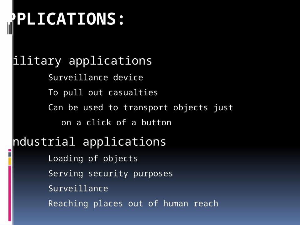
AT89C52 FEATURES• 8K Bytes of In-System Reprogrammable Flash Memory • Endurance: 1,000 Write/Erase Cycles • Fully Static Operation: 0 Hz to 24 MHz • Three-level Program Memory Lock • 256 x 8-bit Internal RAM • 32 Programmable I/O Lines • Three 16-bit Timer/Counters • Eight Interrupt Sources • Programmable Serial Channel • Low-power Idle and Power-down Modes

FEATURES 7805Output Current up to 1A
Output Voltages of 5, 6, 8, 9, 10, 12, 15, 18, 24V
Thermal Overload Protection
Short Circuit Protection
Output Transistor Safe Operating Area Protection

L293D LINE DRIVER
600mA Output current capability per channel
Over temperature protection
Logical “0” input voltage up to 1.5 v
Internal clamp diodes
High voltage, high current four channel dr
Drives inductive loads (DC motor)

L293D PIN CONNECTIONS
Microcontroller
insufficient to
drive motors
It helps to
boost supply to
motors

DC MOTORS
Low torque and high speed devices
Gear set can be used to increase torque at the
cost of speed
The movement of shaft is smooth
Easiest to operate
Can rotate in both directions
Thus speed needs to be controlled to handle it

TOP VIEW
RESULTS

SIDE VIEW
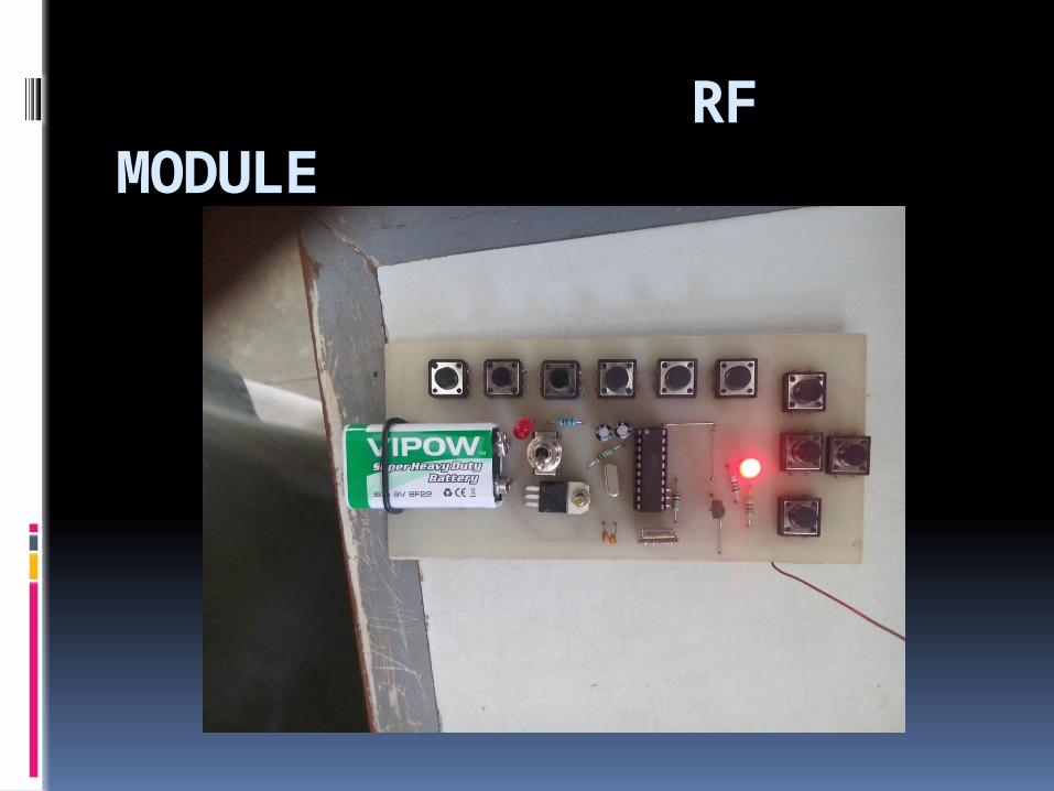
RF MODULE

FUTURE SCOPE
Future we can implement by using a wireless camera
By implementing zigbee technology By using high speed gears the
robotic can move faster nd activity of jaw can be incresed


![Hydraulic Robotic Arm[1]](https://static.cupdf.com/doc/110x72/577c83d31a28abe054b667dc/hydraulic-robotic-arm1.jpg)