REINFORCED VERTICALLY-PERFORATED CLAY-BRICK MASONRY
U. Meyer1
1. ABSTRACT
The paper presents the results of investigations on the suitability of highly perforated clay-brick units (35 % up to 50 % by volume offormed vertical holes) and lightweight mortar for reinforced masonry. These materiais are not standardized in the current German code DIN 1053 part 3 "Reinforced Masonry" /1 / due to lack of test results concerning the compressive strength parallel to the bed-joints, the out-of-plane shearstrength and the bond strength between reinforcement and lightweight mortar in bedjoints. Proposals for design values for reinforced clay-brick masonry are given on the basis ofthe investigations.
2. INTRODUCTION
The use ofbed-joint reinforcement in traditional vertically-perforated clay-brick masonry is an interesting altemative to reinforced concrete structures. Examples for these structures are ring anchors and ring beams, see Fig. 1, as well as reinforced cellar walls exposed to lateral soil pressure. The application of reinforced vertically-perforated claybrick masonry requires a number of design values, e. g. for the compressive strength parallel to the bed-joints, the out-of-plane shear-strength and the bond strength between reinforcement and lightweight mortar in bed-joints. These design values have to be derived from test results if regulations in current standards are not available.
Keywords: Reinforced Masonry, Bed-Joint Reinforcement, Vertically-Perforated Clay-Bricks, Lightweight Mortar, Characteristic Anchorage Bond Strength
lDipL-Ing .. Institut fur Bauforschung, RWTH Aachen, Schinkelstrasse 3, D-52056 Aachen, Gerrnany
1221
Fig 1: Ring anchor in reinforced concrete with additional thermal insulation and in reinforced masonry.
3. REGULATIONS IN CURRENT MASONRY CODES
The current German code DIN 1053 part 3, edition 02.90, contains some restrictions concerning the materiaIs approved for reinforced masonry construction. Units with more than 35 % of formed vertical holes are not alIowed with respect to the unknown loadbearing capacity ofthese units in out-of-plane bending at that time. The design values for the compressive strength of masonry paralIel to the bed-joints for units with less than 35 % of formed vertical holes are reduced to 50% of the values for loading normal to the bed-joints. Mortars are restricted to M 10 or greater with respect to the then uncertain anchorage bond properties between reinforcement and other mortars. Reinforcement has to consist of corrosion-protected ribbed rebars. The maximum bar diameter is given for certain conditions of application (bed-joints, recesses) in order to obtain a proper embedment of the reinforcement. The use of prefabricated bed-joint reinforcement has to be regulated by national technical approvals. The main reason for these restrictions was the lack of test results for other types of materiais.
The current draft of Eurocode 6 /2/ contains no specified requirements concerning units approved for reinforced masonry. As there are no values for anchorage bond for mortars M4 or lower as weIl as for lightweight and thin layer mortar, these mortars are not aIlowed. Reinforcement, plain or ribbed with equivalent corrosion protection, should be in accordance with EN 10080 or EN 10088 respective1y.
4. NECESSARY RESEARCH ACTIVITIES
The large majority of the verticaIly-perforated clay-bricks in Germany which were especially developed to meet the high requirements concerning thermal insulation do not meet the requirements concerning the maximum percentage of formed vertical holes in the German Code on Reinforced Masonry. The application of these units in bed-joint reinforced masonry is nevertheless desirable. The aim of an extensive test programme, sponsored by the German Clay Brick Industry /3/ was the derivation of design methods for vertically-perforated clay-bricks in reinforced masonry based on test results. These results were the base for the draft of a national technical approval /4/. An additional test programme /5/ had the aim to determine suitable values of bond stresses for
1222
reinforcement in very frequently used lightweight mortars LM 700, LM 1000 and general purpose mortar MS.
5. TEST PROGRAMME
5.1 Load-bearing Capacity of Bed-joint Reinforced Clay-brick Masonry Subjected to Out-of-plane Shear and Bending
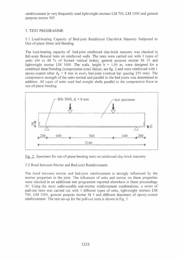
The load-bearing capacity of bed-joint reinforced c1ay-brick masonry was checked in full-scale flexural tests on reinforced walls. The tests were carried out with 3 types of units (44 to 48 % of formed vertical holes), general purpose mortar M 10 and lightweight mortar LM 1000. The walls, height h = 1,00 m, were designed for a combined shearlbending (compression zone) failure, see figo 2 and were reinforced with 1 epoxy-coated rebar ds = 8 mm in every bed-joint (vertical bar spacing 250 mm). The compressive strength ofthe units normal and parallel to the bed-joints was determined in addition. AlI types of units used had straight shells paralle1 to the compressive force in out-of-plane bending.
test specimen
~~~====================================~~~~~
640 560 640 " ., 2240
Fig. 2: Specimen for out-of-plane-bending tests on reinforced c1ay-brick masonry
5.2 Bond between Mortar and Bed-joint Reinforcement
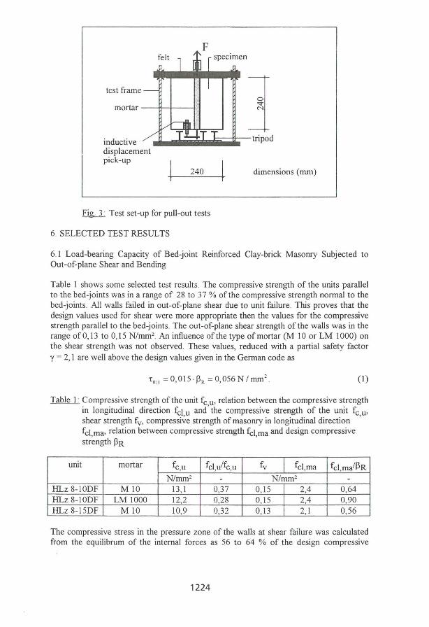
The bond between mortar and bed-joint reinforcement is strongly influenced by the mortar properties in the joint. The influences of units and mortar on these properties were checked in an additional test programme reported elsewhere in these proceedings /6/. Using the most unfavourable unit-mortar reinforcement combinations, a series of pull-out tests was carried out with 3 different types of units, lightweight mortars LM 700, LM 1000, general purpose mortar M 5 and different diameters of epoxy-coated reinforcement. The test set-up for the pull-out tests is shown in Fig. 3.
1223
F felt specimen
test frame
mortar ---+1-1--4!;
inductive -'I .... iiiliiii ••• iiiiiiiliI-tripod displacement pick-up
240 dimensions (mm)
Fig. 3: Test set-up for pull-out tests
6. SELECTED TEST RESULTS
6.1 Load-bearing Capacity of Bed-joint Reinforced Clay-brick Masonry Subjected to Out-of-plane Shear and Bending
Table 1 shows some selected test results . The compressive strength of the units parallel to the bed-joints was in a range of 28 to 37 % ofthe compressive strength normal to the bed-joints. AlI walls failed in out-of-plane shear due to unit faiIure. This proves that the design values used for shear were more appropriate then the values for the compressive strength parallel to the bed-joints. The out-of-plane shear strength ofthe walls was in the range ofO,13 to 0,15 N/mm2 An influence ofthe type ofmortar (M 10 or LM 1000) on the shear strength was not observed. These values, reduced with a partial safety factor y = 2, 1 are well above the design values given in the German code as
' 01 1 = 0,015 ·13 R = 0,056 N I mm2 (1)
Table 1: Compressive strength ofthe unit fc u, relation between the compressive strength in longitudinal direction feI u and' the compressive strength of the unit fc u, shear strength fv, compressi~e strength of masonry in longitudinal direction ' fcl ma, relation between compressive strength feI ma and design compressive str~ngth 13R '
unit mortar fc,u feI ,u/fc,u fv feI,ma fcl,ma/13R N/mm 2 - N/mm2 -
HLz 8-10DF MIO 13,1 0,37 0,15 2,4 0,64 HLz 8-10DF LM 1000 12,2 0,28 0,15 2,4 0,90 HLz 8-15DF MIO 10,9 0,32 0,13 2,1 0,56
The compressive stress in the pressure zone of the walls at shear failure was calculated from the equilibrum of the internaI forces as 56 to 64 % of the design compressive
1224
strength 13R nonnal to the bed-joints for the walls with general purpose mortar MIO and 90 % of the design compressive strength 13R nonnal to the bed-joints for the wa\1 with lightweight mortar LM 1000. These values are in the range of the values detennined in pure compression on two-unit prisms, where values between 54 and 73 % were determined. The real compressive strength in out-of-plane bending must be even higher These results are not surprising, because the externaI shell of the units which determines the strength of the bending pressure zone is nonnallY thicker and therefore stronger than the inner shells which are determening the ultimate load in pure compression.
6 .2 Bond between Mortar and Bed-joint Reinforcement
The compressive strength of the general purpose mortar M5 in the joint is significant1y influenced by the state ofhurnidity ofthe units. Table 2 shows some selected test results . The compressive strength in combination with dry units fc,j = 12,2 N/mm2 was almost 250 % higher then in wet units, fc,j = 4,9 N/mm2 This had a significant influence on the bond properties. The combination of wet c\ay-brick units and M5 tumed out to be the worst case for bond failure too.
Table 2: Bond between mortar and bed-joint reinforcement (Different vertically perforated c\ay-bricks); state ofhurnidity ofthe units (d=dry, w=wet), type of mortar, diameter ds of steel, compressive strength fc,j of mortar in the joint, mean bond stress fbu in the ultimate Iirnit state, mean anchorage length Ibu in the ultimate Iirnit state
Hurnidity Mortar ds fc,j fbu Ibu
mm N/mm2 mm d LM 1000 5 12,6 2,84 220 w LM 1000 5 16,0 4,01 156 d LM 1000 8 11 ,4 1,74 611 d LM 1000 8 11 ,8 2,15 482 d LM 1000 8 16,4 2,42 413 d LM 1000 8 10,5 1,65 606 d LM700 5 4,7 0,94 668 w LM700 5 5,7 1,32 494 d M5 5 12,2 3,80 165 w M5 5 4,9 1,74 362
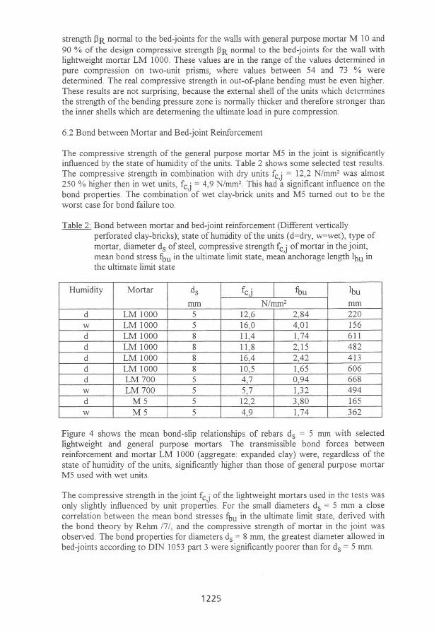
Figure 4 shows the mean bond-slip relationships of rebars ds = 5 mm with selected lightweight and general purpose mortars. The transrnissible bond forces between reinforcement and mortar LM 1000 (aggregate expanded c\ay) were, regardless of the state of hurnidity of the units, significant1y higher than those of general purpose mortar MS used with wet units.
The compressive strength in the joint fc,j ofthe lightweight mortars used in the tests was only slightly influenced by unit propertles. For the small diameters ds = 5 mm a c\ose correlation between the mean bond stresses fbu in the ultimate lirnit state, derived with the bond theory by Rehm /7 /, and the compressive strength of mortar in the joint was observed. The bond properties for diameters ds = 8 mm, the greatest diameter aUowed in bed-joints according to DIN 1053 part 3 were significantly poorer than for ds = 5 mm.
1225
TV in N /mm2
6,-----------------------------------~ ____ _.__rr__.~~ aggregate humidity of unit
5 T perlile wel
V d
• expanded clay wel
C dry
4 • sand wel O dry
3
2
0;---------r--------,---------.--------r--------1 0,00 0,30 0,60 0,90 1,20 1,50
~in mm
Fig. 4: Bond(tv)-slip(ô) relationship for different mortars and reinforcing steel ds = 5 mm
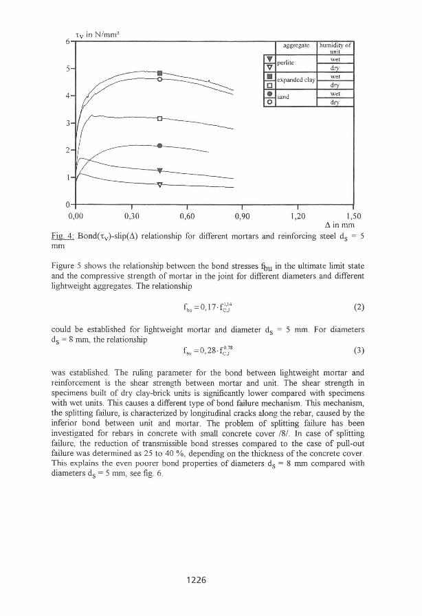
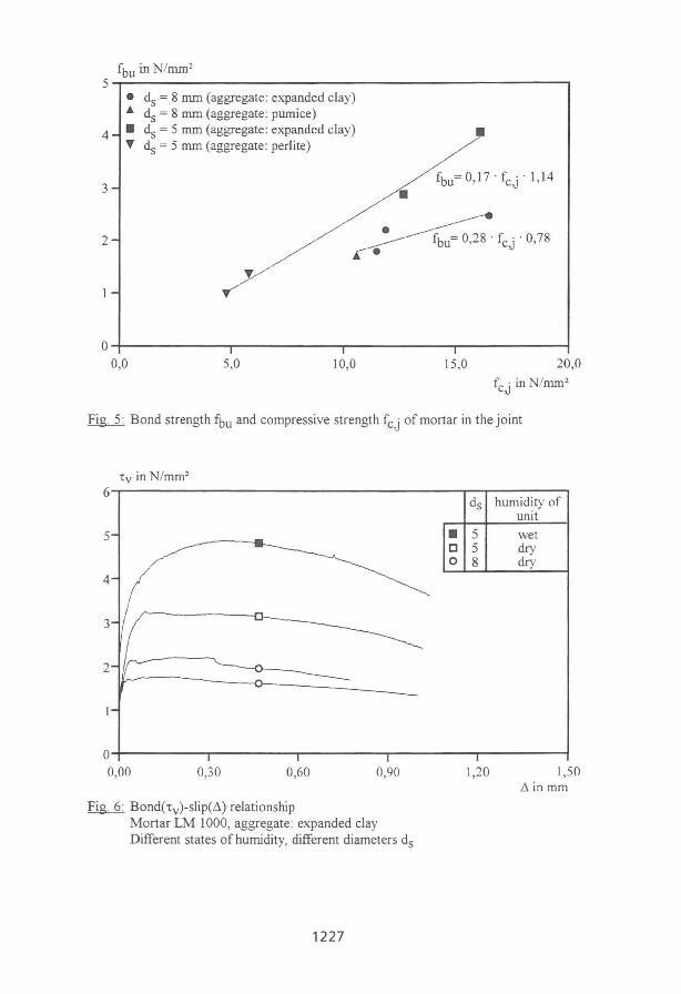
Figure 5 shows the relationship between the bond stresses fbu in the ultimate limit state and the compressive strength of mortar in the joint for different diameters and different lightweight aggregates. The relationship
(2)
could be established for lightweight mortar and diameter ds = 5 mm. For diameters ds = 8 mm, the relationship
(3)
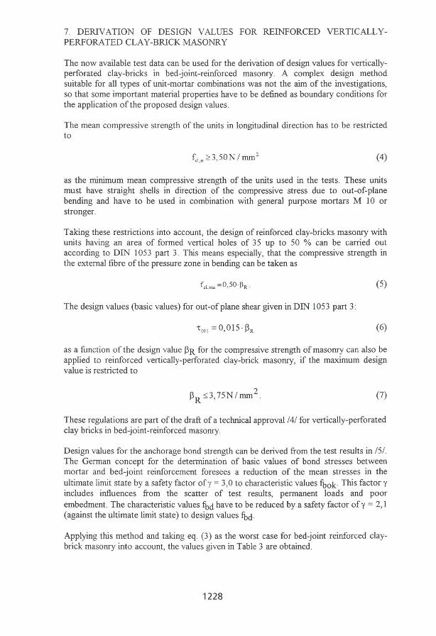
was established. The ruling parameter for the bond between lightweight mortar and reinforcement is the shear strength between mortar and unit. The shear strength in specimens built of dry clay-brick units is significantJy lower compared with specimens with wet units. This causes a different type of bond failure mechanism. This mechanism, the splitting failure, is characterized by longitudinal cracks along the rebar, caused by the inferior bond between unit and mortar. The problem of splitting failure has been investigated for rebars in concrete with small concrete cover /8/. In case of splitting failure, the reduction of transmissible bond stresses compared to the case of pull-out failure was determined as 25 to 40 %, depending on the thickness of the concrete cover. This explains the even poorer bond properties of diameters ds = 8 mm compared with diameters ds = 5 mm, see figo 6.
1226
5,--------------------------------------------------,
4
3
2
• ds = 8 mm (aggregate: expanded c1ay) ... ds = 8 mm (aggregate: pumice) • ds = 5 mm (aggregate: expanded c1ay) ... ds = 5 mm (aggregate: perlite) •
fbu=0,]7 o fCj 0] ,14
•
O;-----------~----------._----------r_--------~ 0,0 5,0 10,0 15,0 20,0
f o in N /nun2
cJ
Fig 5: Bond strength ibu and compressive strength fc,j of mortar in the joint
TV in N/mm 2
6,-------------------------------------~,--------, humidity of ds
unit
5 • 5 wet O 5 dry O 8 dry
4
3
2
O~--------~--------_r--------_r--------~--------~ 0,00 0,30 0,60 0,90
Figo 6: Bond(Tv)-slip(~) relationship Mortar LM 1000, aggregate : expanded c1ay Different states ofhumidity, different diameters ds
1227
1,20 1,50 ôin mm
7. DERIVATlON OF DESIGN VALUES FOR REINFORCED VERTlCALLYPERFORATED CLAY-BRICKMASONRY
The now available test data can be used for the derivation of design values for verticallyperforated cJay-bricks in bed-joint-reinforced masonry. A complex design method suitable for ali types of unit-mortar combinations was not the aim of the investigations, so that some important material properties have to be defined as boundary conditions for the application of the proposed design values.
The mean compressive strength of the units in longitudinal direction has to be restricted to
(4)
as the minimum mean compressive strength of the units used in the tests. These units must have straight shells in direction of the compressive stress due to out-of-plane bending and have to be used in combination with general purpose mortars MIO or stronger.
Taking these restrictions into account, the design of reinforced cJay-bricks masonry with units having an area of formed vertical holes of 35 up to 50 % can be carried out according to DIN 1053 part 3. This means especially, that the compressive strength in the externai fibre of the pressure zone in bending can be taken as
(5)
The design values (basic values) for out-ofplane shear given in DIN 1053 part 3:
(6)
as a function of the design value ~R for the compressive strength of masonry can also be applied to reinforced vertically-perforated cJay-brick masonry, if the maximum design value is restricted to
(7)
These regulations are part of the draft af a technical approval /4/ for vertically-perforated cJay bricks in bed-joint-reinforced masonry.
Design values for the anchorage bond strength can be derived from the test results in /51. The German concept for the detennination of basic values of bond stresses between mortar and bed-joint reinforcement foresees a reduction of the mean stresses in the ultimate limit state by a safety factor of y = 3,0 to characteristic values fbok . This factor y incJudes influences from the scatter of test results, permanent loads and poor embedment. The characteristic values fbd have to be reduced by a safety factor of y = 2,1 (against the ultimate limit state) to design values fbd .
Applying this method and taking eg. (3) as the worst case for bed-joint reinforced cJaybrick masonry into account, the values given in Table 3 are obtained.
1228
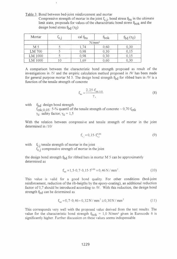
Table 3: Bond between bed-joint reinforcement and mortar Compressive strength of mortar in the joint fc,j, bond stress fbu in the ultimate limit state, proposals for values ofthe characteristic bond stress fbok and the design bond stress fbd (10)
Mortar fc,j cal fbu fbok fbd (10)
N/mm2
M5 5 1,74 0,60 0,30 LM700 5 0,98 0,30 0, 15
LM 1000 5 0,98 0,30 0, 15 LM 1000 10 1,69 0,60 0,30
A comparison between the characteristic bond strength proposed as result of the investigations in 151 and the empiric calculation method proposed in 191 has been made for general purpose mortar M 5. The design bond strength fbd for ribbed bars in /91 is a function ofthe tensile strength of concrete
with fbd : design bond strength
2,25· f,tk:o.os fbd = -_-=-::.:::::.-
fctkO 05 : 5-% quantil of the tensile strength of concrete - 0,70 fctk k ~afety factor; Yc = 1,5
(8)
With the relation between compressive and tensile strength of mortar In the joint determined in 11 0/
with: ft ,j tensile strength of mortar in the joint fc,j compressive strength of mortar in the joint
the design bond strength fbd for ribbed bars in mortar M 5 can be approximately determined as
(9)
(lO)
Tlús value is valid for a good bond quality. For other conditions (bed-joint reinforcement, reduction of the rib-heigths by the epoxy-coating), an additional reduction factor of 0,7 should be introduced according to /9/. With tlús reduction, the design bond strength fbd can be determined as
f bd =0, 7·0,46=0,32N I mm 2 =:0,30N 1 mm 2 (11)
Tlús corresponds very well with the proposed value derived from the test results . The value for the characteristic bond strength fbok = 1,0 N /mm2 given in Eurocode 6 is significantly Iúgher. Further discussion on these values seems indispensable.
1229
8. CONCLUSIONS
The design of load-bearing reinforced masonry with vertically-perforated c1ay-bricks is possible applying the drafted national technical approval /4/ and the suggested amendment conceming the use of lightweight mortar LM 1000 in reinforced c1ay-brick masonry.
A discussion of the values for the anchorage bond strength indicated in Eurocode 6 is indispensable. As a result of this discussion, appropriate values for anchorage bond should be defined for different boundary conditions (bed-joints, chases, cavities). Values for the anchorage bond strength between lightweight mortar LM 1000 and reinforcement should be inc1uded in Eurocode 6.
9. REFERENCES
/1 / DIN 1053 Teil3 02.90. Mauerwerk; Bewehrtes Mauerwerk; Berechnung und Ausfuhrung
/2/ prENV 1996-1-1 10.93. Eurocode 6; Design ofMasonry Structures; Part 11 : General Rules. Rules for reinforced and unreinforced masonry, crack and deflection control. Draft
/3/ Meyer, U : Versuche zur Zulassung von bewehrtem Ziegelmauerwerk mit Lochanteilen > 35 %. Aachen: Institut fur Bauforschung der RWTH Aachen, 1991. - Prüfbericht Nr. A 2245
/4/ Deutsches Institut fur Bautechnik: Hochlochziegel und Leichthochlochziegel fur Mauerwerk mit horizontaler Bewehrung in den Lagerfugen. Zulassung Z-17 .1-480 Berlin: Entwurf04.93
/5/ Meyer, U : Verbund zwischen Lagerfugenbewehrung und Leichtmórtel in HLzMauerwerk. Aachen: Institut fur Bauforschung der RWTH Aachen, 1993. -Prüfbericht Nr. A 2633
/6/ Schubert, P. ; Meyer, U : Grundlagenuntersuchungen zum Einflu/3 der Steineigenschaften auf die Mórteleigenschaften in HLz-Mauerwerk. Aachen: Institut fur Bauforschung der RWTH Aachen, 1994. - Forschungsbericht Nr. F 461
/7/ Rehm, G.: Über die Grundlagen des Verbundes zwischen Stahl und Beton. Berlin : Emst & Sohn. - In: Schriftenreihe des Deutschen Ausschusses fur Stahlbeton (1961), Nr. 138
/8/ Eligehausen, R.; Kreller, H.; Langer, P.; IWB: Untersuchungen zum Verbundverhalten gerippter Bewehrungsstabe mit praxisüblicher Betondeckung. Stuttgart: Institut fur Werkstoffe im Bauwesen. In: Mitteilungen des Instituts fur Werkstoffe im Bauwesen (1989), Nr. 5
/9/ DIN V ENV 1992 Teill-l 06.92. Eurocode 2 Planung von Stahlbeton- und Spannbetontragwerken; Grundlagen und Anwendungsregeln fur den Hochbau
/10/ Schief3l, P.; Schubert, P.; Meyer, U: Rissesicherung und Ri/3breitenbeschrankung in bewehrten Mauerwerkbauteilen. Aachen: Institut fur Bauforschung, 1994. -Forschungsbericht Nr. F 418
1230