Reducer Catalog
Speed Reducers for Precision Motion Control
Gear Units CSF-2UP Engineering Data

2
Excellent Technology for Evolving IndustriesHarmonic Drive® actuators utilize high-precision, zero-backlash Harmonic Drive® precision gears and play critical roles in robotics, semiconductor manufacturing equipment, factory automation equipment, medical diagnostics and surgical robotics. Additionally, our products are frequently used in mission-critical spaceflight applications which capture the human spirit.
With over 50 years of experience, our expert engineering and production teams continually develop enabling technologies for the evolving motion control market. We are proud of our outstanding engineering capabilities and successful history of providing customer specific solutions to meet their application requirements.
Harmonic Drive LLC continues to develop enabling technologies for the evolving motion control market, which drives the pace of global innovation.
C. Walton MusserPatented Strain Wave Gearing in 1955
■ Development of HarmonicDrive® Speed Reducers
Harmonic Drive® gears have been evolving since the strain wave gear was first patented in 1955. Our innovative development and engineering teams have led us to significant advances in our gear technology. In 1988, Harmonic Drive successfully designed and manufactured a new tooth profile, the "S" tooth. Since implementing the "S" tooth profile, improvement in life, strength and torsional stiffness have been realized. In the 1990s, we focused engineering efforts on designing gears featuring space savings, higher speed, higher load capacity and higher reliability. Then in the 2000s, significant reduction in size and thickness were achieved, all while maintaining high precision specifications.
0° 90° 180° 360°
Wave GeneratorThe Wave Generator is a thin, raced-ball bearing fitted onto an elliptical hub. This serves as a high-efficiency torque converter and is generally mounted onto the input or motor shaft.
FlexsplineThe Flexspline is a non-rigid, thin cylindrical cup with external teeth on the open end of the cup. The Flexspline fits over the Wave Generator and takes on its elliptical shape. The Flexspline is generally used as the output of the gear.
Circular SplineThe Circular Spline is a rigid ring with internal teeth. It engages the teeth of the Flexspline across the major axis of the Wave Generator ellipse. The Circular Spline has two more teeth than the Flexspline and is generally mounted onto a housing.
Circular Spline
Wave Generator
Flexspline
The Flexspline is slightly smaller in diameter than the Circular Spline and usually has two fewer teeth than the Circular Spline. The elliptical shape of the Wave Generator causes the teeth of the Flexspline to engage the Circular Spline at two opposite regions across the major axis of the ellipse.
As the Wave Generator rotates the teeth of the Flexspline engage with the Circular Spline at the major axis.
For every 180 degree clockwise movement of the Wave Generator, the Flexspline rotates counterclockwise by one tooth in relation to the Circular Spline.
Each complete clockwise rotation of the Wave Generator results in the Flexspline moving counterclockwise by two teeth from its original position, relative to the Circular Spline. Normally, this motion is taken out as output.
Operating Principle of Gears
™
A simple three-element construction combined with the unique operating principle puts extremely high reduction ratio capabilities into a very compact and lightweight package. The high-performance attributes of this gearing technology including, zero-backlash, high-torque-to-weight ratio, compact size, and excellent positional accuracy, are a direct result of the unique operating principles.

3
Excellent Technology for Evolving IndustriesHarmonic Drive® actuators utilize high-precision, zero-backlash Harmonic Drive® precision gears and play critical roles in robotics, semiconductor manufacturing equipment, factory automation equipment, medical diagnostics and surgical robotics. Additionally, our products are frequently used in mission-critical spaceflight applications which capture the human spirit.
With over 50 years of experience, our expert engineering and production teams continually develop enabling technologies for the evolving motion control market. We are proud of our outstanding engineering capabilities and successful history of providing customer specific solutions to meet their application requirements.
Harmonic Drive LLC continues to develop enabling technologies for the evolving motion control market, which drives the pace of global innovation.
C. Walton MusserPatented Strain Wave Gearing in 1955
■ Development of HarmonicDrive® Speed Reducers
Harmonic Drive® gears have been evolving since the strain wave gear was first patented in 1955. Our innovative development and engineering teams have led us to significant advances in our gear technology. In 1988, Harmonic Drive successfully designed and manufactured a new tooth profile, the "S" tooth. Since implementing the "S" tooth profile, improvement in life, strength and torsional stiffness have been realized. In the 1990s, we focused engineering efforts on designing gears featuring space savings, higher speed, higher load capacity and higher reliability. Then in the 2000s, significant reduction in size and thickness were achieved, all while maintaining high precision specifications.
0° 90° 180° 360°
Wave GeneratorThe Wave Generator is a thin, raced-ball bearing fitted onto an elliptical hub. This serves as a high-efficiency torque converter and is generally mounted onto the input or motor shaft.
FlexsplineThe Flexspline is a non-rigid, thin cylindrical cup with external teeth on the open end of the cup. The Flexspline fits over the Wave Generator and takes on its elliptical shape. The Flexspline is generally used as the output of the gear.
Circular SplineThe Circular Spline is a rigid ring with internal teeth. It engages the teeth of the Flexspline across the major axis of the Wave Generator ellipse. The Circular Spline has two more teeth than the Flexspline and is generally mounted onto a housing.
Circular Spline
Wave Generator
Flexspline
The Flexspline is slightly smaller in diameter than the Circular Spline and usually has two fewer teeth than the Circular Spline. The elliptical shape of the Wave Generator causes the teeth of the Flexspline to engage the Circular Spline at two opposite regions across the major axis of the ellipse.
As the Wave Generator rotates the teeth of the Flexspline engage with the Circular Spline at the major axis.
For every 180 degree clockwise movement of the Wave Generator, the Flexspline rotates counterclockwise by one tooth in relation to the Circular Spline.
Each complete clockwise rotation of the Wave Generator results in the Flexspline moving counterclockwise by two teeth from its original position, relative to the Circular Spline. Normally, this motion is taken out as output.
Operating Principle of Gears
™
A simple three-element construction combined with the unique operating principle puts extremely high reduction ratio capabilities into a very compact and lightweight package. The high-performance attributes of this gearing technology including, zero-backlash, high-torque-to-weight ratio, compact size, and excellent positional accuracy, are a direct result of the unique operating principles.

Engi
neer
ing
Dat
aC
ompo
nent
Set
sG
ear U
nits
Phas
e A
djus
ters
Gea
rhea
ds &
Act
uato
rs
Engi
neer
ing
Dat
aC
ompo
nent
Set
sG
ear U
nits
Phas
e A
djus
ters
Gea
rhea
ds &
Act
uato
rs
157
CSG-2UK
Gear Unit CSF-2UP
158159159160160161162162163164165
CSF-2UP mini Series
Features
Technical data
Ordering code
Rating table
Mounting and Installation
Checking output bearing
Lubrication
Outline drawing anddimensions
Wave generator hole diameter
Mechanical accuracy
Efficiency
No load running torque

Engi
neer
ing
Dat
aC
ompo
nent
Set
sG
ear U
nits
Phas
e A
djus
ters
Gea
rhea
ds &
Act
uato
rs
Engi
neer
ing
Dat
aC
ompo
nent
Set
sG
ear U
nits
Phas
e A
djus
ters
Gea
rhea
ds &
Act
uato
rs
158
* The motor mounting flange is designed and sold as an option. Please let us know the required dimension shown in Figure 168-1 on page 168 if you need the flange designed.
* Installation of the motor mounting flange and motor must be performed by the customer. For proper installation, refer to pages 165 through 168.* The special specification: SP may include other special specifications.
(2) Special specifications: SP When ordering the combination of speed reducer and motor mounting flange
(1) Special specification: Blank When ordering the speed reducer only
Gear Motor mounting flange
Motor
(Prepared by the customer)
Features
Figure 158-1
The CSF-2UP gear units are the newest models in the CSF mini-series lineup. These new gear units have an ultra-flat configuration with high-moment stiffness. Har-monic Drive® gear units are zero-backlash gears with a precision output bearing with an integrated housing. The new models are lightweight and extremely flat. Cross roller bearing used at the output flange enables the CSF-2UP gearheads to offer high-moment stiffness. The CSF-2UP mini gearheads are ideally suited for small robots or equipment requiring an ultra-compact solution.
Features Zero backlash High-positioning accuracy Compact and lightweight High-torque capacity High-radial, axial, and moment load capacity Cross roller bearing Ratios: 30:1 to 100:1
Gear Unit CSF-2UP

Engi
neer
ing
Dat
aC
ompo
nent
Set
sG
ear U
nits
Phas
e A
djus
ters
Gea
rhea
ds &
Act
uato
rs
Engi
neer
ing
Dat
aC
ompo
nent
Set
sG
ear U
nits
Phas
e A
djus
ters
Gea
rhea
ds &
Act
uato
rs
159
Ordering Code
Size Ratio
Rated torque at input speed
2000 rpm
Limit for repeated peak
torque
Limit for average torque
Limit for momentary peak torque
Maximum input speed
Limit for aver-age input speed
Moment of inertia(1/4GD2)
Nm Nm Nm Nm rpm rpm kgcm2
8
30 0.9 1.8 1.4 3.3
8500 3500 4.0 × 10-350 1.8 3.3 2.3 6.6
100 2.4 4.8 3.3 9.0
11
30 2.2 4.5 3.4 8.5
8500 3500 1.5 × 10-250 3.5 8.3 5.5 17
100 5.0 11 8.9 25
14
30 4.0 9.0 6.8 17
8500 3500 4.0 × 10-250 5.4 18 6.9 35
100 7.8 28 11 54
Table159-2
CSF - 14 - 100 - 2UP - SP
Series Size Reduction ratio Model Special specifications
CSF series
8 30 50 1002UP
(High-moment stiffness)
Blank = standard product SP = Special specification code
(Including the motor mounting flange option)11 30 50 100
14 30 50 100
Rating table
Table159-1
Gear Unit CSF-2UP

Engi
neer
ing
Dat
aC
ompo
nent
Set
sG
ear U
nits
Phas
e A
djus
ters
Gea
rhea
ds &
Act
uato
rs
Engi
neer
ing
Dat
aC
ompo
nent
Set
sG
ear U
nits
Phas
e A
djus
ters
Gea
rhea
ds &
Act
uato
rs
160
Cross Roller Bearing Specifications
■ Checking procedure
Table 160-2
A precise cross roller bearing is built in the CSF-2UP for the purpose of directly supporting external load (on the output side).In order to fully achieve the performance of the unit, check the maximum moment load, cross roller bearing life, and static safety coefficient.
Grease is the standard lubrication for CSF-2UP mini series. There is no need to add or apply grease upon installation since the products are shipped with the grease applied.
(1) Checking the maximum moment load (M max)
(2) Checking the life
(3) Checking the static safety coefficient
Calculate the maximum moment load (M max).
Calculate the average radial load (Frav) and the average axial load (Faav).
Calculate the static equivalent radial load coefficient (Po).
Check the static safety coefficient (fs).
Calculate the radial load coefficient (X) and an axial load coefficient (Y). Calculate the life and check it
Maximum moment load (M max) ≤ allowable moment (Mc)
*1 The basic dynamic load rating is referred to as a constant static radial load so that the basic dynamic load rating of the bearing is to be a million rotations.
*2 The basic static load rating is referred to as a static load that provides a constant level contact stress (4kN/mm2) at the center of the contact side between the rolling element that bears the maximum load and the orbit.
*3 The allowable moment load is referred to as the maximum moment load that can be applied to the output bearing while the basic perfor-mance can be retained within the range of the maximum moment load that can be operable.
*4 The values of the moment stiffness are the reference values. The minimum value is approximately 80% of the display value.
Lubricated area Gear Cross roller bearing
Lubrication Harmonic Grease® SK-2
Manufacturer Harmonic Drive Systems Inc.
Base oil Refined oil
Base Viscosity (25°C) 265 to 295
Thickening agent Lithium soap base
Drop point 198°C
Appearance Green color
■ Output bearing specifications Table 160-1
Size
Pitch circle Offset Basic rated loadAllowable moment
load Mc*3Moment stiffness
Km*4dp R Basic dynamic
rated load C*1Basic static rated
load Co*2
mm mm × 102 N × 102 N Nm Nm/rad
8 35 12.9 58 80 15 2.0 × 10⁴
11 42.5 14 65 99 40 4.0 × 10⁴
14 54 14 74 128 75 8.0 × 10⁴
Lubrication
Gear Unit CSF-2UP

Engi
neer
ing
Dat
aC
ompo
nent
Set
sG
ear U
nits
Phas
e A
djus
ters
Gea
rhea
ds &
Act
uato
rs
Engi
neer
ing
Dat
aC
ompo
nent
Set
sG
ear U
nits
Phas
e A
djus
ters
Gea
rhea
ds &
Act
uato
rs
161
■ Dimensions8 11 14
øA 66 80 100
B 24.8 27 33.5
C 13 13.5 18.5
D 9 11.5 12
E 2.8 2 3
F 3 3.5 3.5
G 5 5 8
H* 1.1 1.6 3.5
I 7.2 8.3 10.5
J 12.9 14 14
øK 49 59 74
øL 48 58 73
øM 33.5 41 52.5
øN 30 44 52
øO 5 5 8
□P 50±1 60±1 75±1
øQ 25.5 33 44
øR 58 70 88
S 6 6 6
T M3 × 5 M4 × 5 M5 × 7
U 4 4 4
øV 3.5 4.5 5.5
øW 52 63 70.71
X 35° 33.5° 55°
Y 4 4 4
Z M3 × 5 M3 × 6 M4 × 8
Mass (g) 200 330 620
Symbol Size
0-0.3
0-0.7
0-0.8
Unit: mm Table 161-1
(Max
imum
dia
met
er
of th
e ro
tatin
g pa
rt)
d (O-ring) (provided with the product)
øK h
7
øL
øM h
7
øO H
7 øN h
7
øA
øW
XC D E
GF
J
B
□P
øR
øQ
S-T equally spaced
Y-Z equally spacedU-øV equally spaced
45º
■ Wave generator mounting diagramFigure 161-2
Figure 161-1
* Dimension H is the mounting position in the shaft direction and tolerance of the three parts (wave generator, flexspline, circular spline). Strictly observe these dimensions as they affect the performance and strength.
a-bSet screw
a-bSet screw
E
H*
BD
E
H*
BD
lc
lc
Sizes 8 and 11 Size 14
8 11 14
a 2 2 2
b M3×4 M3×4 M4×4
c 10.2 11.3 14
d ø29.8×0.8 ø54.0×1.2 ø58.4×1.3
Table 161-2
SymbolSize
Outline DimensionsCross Roller Bearing Specifications
■ Checking procedure
Gear Unit CSF-2UP

Engi
neer
ing
Dat
aC
ompo
nent
Set
sG
ear U
nits
Phas
e A
djus
ters
Gea
rhea
ds &
Act
uato
rs
Engi
neer
ing
Dat
aC
ompo
nent
Set
sG
ear U
nits
Phas
e A
djus
ters
Gea
rhea
ds &
Act
uato
rs
162
Wave Generator Hole Diameter Dimension
Mechanical Accuracy
The hole diameter dimension (as shown in Table 161-1 on page 161, øO) can be changed in accordance with the shaft diameter of the mounting motor within the range shown in the table below:
By using high-accuracy and high-stiffness cross roller bearings, the CSF-2UP mini series, achieves high accuracy. The mechanical accuracy on the output side is shown below.
Symbol FeatureSize
8 11 14
a Output shaft axial runout 0.010
b Concentricity of the mounting pilot 0.040
c Output flange surface runout 0.010
d Parallelism between the mounting face and the output flange face 0.040
8 11 14
øO H7 2 to 8 3 to 8 4 to 10
Symbol Size
Figure 162-1
(Note) Values are based on the Total Indicator Reading (T.I.R.).
* The special specification is applied to the entire unit when a hole diameter is changed. For information on the dimensions, please contact our sales representatives.* The wave generator of a standard product is a solid wave generator. The Oldham type (self-aligning mechanism) is included in the special specification.
Table 162-1
Table 162-2
Gear Unit CSF-2UP

Engi
neer
ing
Dat
aC
ompo
nent
Set
sG
ear U
nits
Phas
e A
djus
ters
Gea
rhea
ds &
Act
uato
rs
Engi
neer
ing
Dat
aC
ompo
nent
Set
sG
ear U
nits
Phas
e A
djus
ters
Gea
rhea
ds &
Act
uato
rs
163
Load torque Rated torque indicated in the rating table
LubricantGrease
lubrication
Name Harmonic Grease® SK-2
Quantity Recommended quantity
Graph 163-10Graph 163-9Graph 163-8
Graph 163-7Graph 163-6Graph 163-5
Graph 163-4Graph 163-3Graph 163-2
-10 100 20 4030
Ratio 30100
908070605040302010
0
Effi
cien
cy (%
)
Ratio 50100
908070605040302010
0-10 100 20 4030
Effi
cien
cy (%
)
Ratio 100
Effi
cien
cy (%
)
100908070605040302010
0-10 100 20 4030
500rpm 1000rpm 2000rpm 3500rpmInput rotational speed
Input rotational speed 500r/min 1000r/min 2000r/min 3500r/min
Ratio 30
-10 100 20 4030
100908070605040302010
0
Effi
cien
cy (%
)
Ratio 50
-10 100 20 4030
100908070605040302010
0
Effi
cien
cy (%
)
Ratio 100
-10 100 20 4030
100908070605040302010
0
Effi
cien
cy (%
)Size: 8
Ratio 50
Effi
cien
cy (%
)
100908070605040302010
0-10 100 20 4030
Ratio 30100
908070605040302010
0
Effi
cien
cy (%
)
-10 100 20 4030Ambient Temperature (oC) Ambient Temperature (oC) Ambient Temperature (oC)
Ambient Temperature (oC) Ambient Temperature (oC) Ambient Temperature (oC)
Ambient Temperature (oC) Ambient Temperature (oC) Ambient Temperature (oC)
Ratio 100100
908070605040302010
0-10 100 20 4030
Effi
cien
cy (%
)
Size: 14
Size: 11
■ Efficiency compensation coefficient
■ Efficiency at rated torque
The efficiency varies depending on the following conditions.• Reduction ratio • Load torque• Input rotating speed • Temperature• Lubrication (Type and quantity)
Measurement condition
Efficiency compensation coefficient
The efficiency compensation coefficient is calculated according to graph 6-1: Ke = 0.99Efficiency η when load torque is 2.0 Nm is calculated: η = Ke•ηR= 0.99 × 77% = 76%* When load torque is larger than rated torque, efficiency compensation coefficient Ke = 1.
The value of efficiency drops when load torque is lower than rated torque.Calculate the compensation coefficient Ke from graph 6-1 and calculate the value of efficiency with the reference to the efficiency compensation calculation formula.
Torque ratio α is 0.83 since the rated torque for size 8 and reduction ratio 100 is 2.4 Nm. (α = 2.0 / 2.4 ≈ 0.83)
Example: Calculate efficiency η (%) for the CSF-8-100-2UP under the following conditions: Input rotational speed 1000 rpm Load torque: 2.0 NmLubrication method: Grease lubricantLubricant temperature: 20°C
1.0
Com
pens
atio
n co
effic
ient
Ke
0.9
0.8
0.7
0.6
0.5
0.4
0.3
0 0.1 0.2 0.3 0.4 0.5 0.6 0.7 0.8 0.9 1.0
Torque ratio α =
Torque ratio α
Load torqueRated torque
η = Ke = Efficiency at rated torque
R
R
ηη
Table 163-1
Graph 163-1
Efficiency
Gear Unit CSF-2UP

Engi
neer
ing
Dat
aC
ompo
nent
Set
sG
ear U
nits
Phas
e A
djus
ters
Gea
rhea
ds &
Act
uato
rs
Engi
neer
ing
Dat
aC
ompo
nent
Set
sG
ear U
nits
Phas
e A
djus
ters
Gea
rhea
ds &
Act
uato
rs
164
Ratio 100:1
Lubricant Grease lubricant Name Harmonic Grease® SK-2
Torque value is measured after 2 hours at 2000rpm input.
30 50
8 0.49 0.22
11 0.81 0.36
14 1.25 0.55
■ Compensation Value in Each Ratio
■ No load running torque for reduction ratio 100
No-load running torque is the torque which is required to rotate the input side (high speed side), when there is no load on the output side (low speed side).* For details about the values, please contact us.
Measurement condition
No-load running torque compensation value
The no-load running torque of the gear varies with ratio. Graphs 164-1 through 164-4 show the value of reduction ratio 100. Other reduction ratios must be calculated by adding the compensation value indicated in Table 164-2
Input rotational speed 500rpm
No-
load
runn
ing
torq
ue (N
cm)
Size
100.0
10.0
1.0
0.1-10 10 20 30 400
8
11
14
Input rotational speed 2000rpm
No-
load
runn
ing
torq
ue (N
cm)
Size
100.0
10.0
1.0
0.1-10 10 20 30 400
8
11
14
Input rotational speed 3500rpm
No-
load
runn
ing
torq
ue (N
cm)
Size
100.0
10.0
1.0
0.1-10 10 20 30 400
8
11
14
Input rotational speed 1000rpm
No-
load
runn
ing
torq
ue (N
cm)
Size
100.0
10.0
1.0
0.1-10 10 20 30 400
8
11
14
*Average value is X in this graph.
Graph 164-1 Graph 164-2
Graph 164-3 Graph 164-4
Ambient Temperature (oC)Ambient Temperature (oC)
Ambient Temperature (oC)Ambient Temperature (oC)
SizeRatio
Unit: mm Table 164-2
Table 164-1No-load running torque
Gear Unit CSF-2UP

Engi
neer
ing
Dat
aC
ompo
nent
Set
sG
ear U
nits
Phas
e A
djus
ters
Gea
rhea
ds &
Act
uato
rs
Engi
neer
ing
Dat
aC
ompo
nent
Set
sG
ear U
nits
Phas
e A
djus
ters
Gea
rhea
ds &
Act
uato
rs
165
The sealing structure as shown is required for mounting the motor for the purpose of grease leakage prevention and of maintaining the high-durability of the HarmonicDrive® gear.
Be sure that the motor shaft does not protrude from the wave generator more that permitted in Table 165-2 below. (Refer also to Figure 165-1)
■ Precautions when installing the motor
* There is no need to apply a seal agent on the output flange because it includes a seal.
■ Sealing
Table 165-1
8 11 14
A 2.5 4.5 6
Unit: mm Table 165-2
DimensionSize
Area requiring sealing
Motor mounting flange
On the gear side(On the reducer side)
On the motor side
Motor output shaft
Screw hole area
Recommended sealing method
Using O-ring (provided with our product)
Please select a motor output shaft with oil seal attached.If the oil seal is not provided, employ a design where the oil seal is attached to the motor mounting flange.Use the screw lock agent with sealing effect (LOCTITE® 242 is recommended), or use the sealing tape.
O-ring, seal agent, seal washer, and others (Take care regarding the distortion on the plane and how the O-ring is engaged)
Example of motor mounting is shown below:
Example of Mounting
A
Speed reducer
Output flange
O-ring (provided with the product)
Motor mounting flange
O-ring or seal agent
Seal washer
Motor
Figure 165-1
Gear Unit CSF-2UP

Engi
neer
ing
Dat
aC
ompo
nent
Set
sG
ear U
nits
Phas
e A
djus
ters
Gea
rhea
ds &
Act
uato
rs
Engi
neer
ing
Dat
aC
ompo
nent
Set
sG
ear U
nits
Phas
e A
djus
ters
Gea
rhea
ds &
Act
uato
rs
166
Installation accuracy
Installation and transmission torque
In order to fully achieve the excellent performance of the CSF-2UP, maintain the recommended installation tolerances shown below:
C部 B部
A部
A
Motor mounting flange face
Wave generator mounting facebcφ◎ A A
a A
Recommended housing tolerance H7
Recommended tolerance of the shaft h6
Figure 166-2
Figure 166-1
8 11 14
a Adapter surface 0.010 0.011 0.011
b Wave generator installation surface 0.006 0.007 0.008
c Concentricity of the input shaft 0.006 0.007 0.016
ToleranceSize
Unit: mm Table 166-1
Area C
Area A
Area B
Gear Unit CSF-2UP

Engi
neer
ing
Dat
aC
ompo
nent
Set
sG
ear U
nits
Phas
e A
djus
ters
Gea
rhea
ds &
Act
uato
rs
Engi
neer
ing
Dat
aC
ompo
nent
Set
sG
ear U
nits
Phas
e A
djus
ters
Gea
rhea
ds &
Act
uato
rs
167
Table 167-1
Table 167-2
Table 167-3
8 11 14
Number of bolts 4 4 4
Bolt size M3 M3 M4
Mounting P.C.D. mm 52 63 70.7
Tightening torque* Nm 0.85 0.85 2.0
Minimum screw length mm 3.6 3.6 4.8
Transmission torque* Nm 18 22 44
8 11 14
Number of bolts 4 4 4
Bolt size M3 M4 M5
Mounting P.C.D. mm 58 70 88
Tightening torque* Nm 1.2 2.7 5.4
Minimum screw length mm 3.6 4.8 6.0
Transmission torque* Nm 29.0 59.1 119
8 11 14
Number of bolts 6 6 6
Bolt size M3 M4 M5
Mounting P.C.D. mm 25.5 33.0 44.0
Tightening torque* Nm 2.0 4.5 9.0
Minimum screw length mm 3.6 4.8 6.0
Transmission torque* Nm 31.9 69.6 184
■ Mounting on the flange
■ Installation into the equipment
■ Mounting load into the output
When the CSF-2UP mini series is installed on the motor, check the flatness of the mounting face and assure that holes are free from burrs, then fasten the reducer to the mounting flange using bolts.
* Recommended bolt: JIS B 1176 hexagon socket head bolt, tensile strength rank: JIS B 1051 12.9 or higher
* When the part of the mounting destination is made of steel* Recommended bolt: JIS B 1176 hexagon socket head bolt, tensile strength rank: JIS B 1051 12.9 or higher
There is no need to apply a sealing compound to the output flange because it includes a seal.* Recommended bolt: JIS B 1176 hexagon socket head bolt, tensile strength rank: JIS B 1051 12.9 or higher
When the CSF-2UP mini series is installed into the equipment, check the flat-ness of the mounting face and assure that holes are free from burrs, then fasten the reducer to the equipment using bolts.
Mount the load to the output side of the CSF-2UP mini series by taking into consideration the cross roller bearing specifications.
Size
Size
Size
Item
Item
Item
A
B
C
Gear Unit CSF-2UP

Engi
neer
ing
Dat
aC
ompo
nent
Set
sG
ear U
nits
Phas
e A
djus
ters
Gea
rhea
ds &
Act
uato
rs
Engi
neer
ing
Dat
aC
ompo
nent
Set
sG
ear U
nits
Phas
e A
djus
ters
Gea
rhea
ds &
Act
uato
rs
168
Gear Unit CSF-2UP
Cross section X-X
*Note 1
*Notes 2 and 3
D-cut shaft
Shaft with keyhole
X
X
□G
I-J equally spaced
D
FE
øB CøA
M
NK L
øH
The motor mounting flange is provided by our company.Please let us know dimensions A through J (when the keyhole is attached: A through N) described in Figure 168-1 when ordering because the motor dimension is required for designing.
* Note 1. H: Mounting hole pitch diameter or pitch angular dimension* Note 2. I: Total number of mounting holes* Note 3. J: Tap hole nominal diameter and hole depth or through hole diameter* Note 4. Please let us know the O-ring dimension when it is used on the motor and the motor mounting flange connecting part.
Motor mounting flange
Figure 168-1

6
Engineering Data
008
Component
035
035
061
079
103
111
Unit
123
123
145
157
169
195
209
227
267
Additional Products
319
319
Phase Adjuster
287
287
303
311
324
325
Engineering Data
Component Sets
• CSG/CSF
• CSD
• SHG/SHF
• FB
• FR
Gear Units
Differential Gear
• CSG/CSF-2UH
• CSG-2UK
• CSF-2UP
• CSF-mini
• CSF-supermini
• CSD-2UH/2UF
• SHG/SHF-2UH/2UJ/2SH/2SO
• SHD-2SH/2UH
• FD
• FBB
• HDI
Other Products
Warranty period, terms and trademark
Safety®
• Gearheads and Actuators
Eng
inee
ring
Dat
aC
ompo
nent
Set
sG
ear
Uni
tsP
hase
Adj
uste
rsG
earh
eads
& A
ctua
tors

Engi
neer
ing
Dat
aC
ompo
nent
Set
sG
ear U
nits
Phas
e A
djus
ters
Gea
rhea
ds &
Act
uato
rs
Engi
neer
ing
Dat
aC
ompo
nent
Set
sG
ear U
nits
Phas
e A
djus
ters
Gea
rhea
ds &
Act
uato
rs
8
Engineering DataEn
gine
erin
g D
ata
Com
pone
nt S
ets
Gea
r Uni
tsPh
ase
Adj
uste
rsG
earh
eads
& A
ctua
tors
Grease lubricantPrecautions on using Harmonic Grease® 4B No.2
Oil lubricantLubricant for special environments
Tooth profile S tooth profile
Rotational direction and reduction ratio
Rating table definitions
Life
Torque limits
Product sizing and selection
Cup style
Lubrication
Silk hat style
Pancake style
Engineering Data
Starting torque
Backdriving torque
No-load running torque
Efficiency
Design guidelines
Assembly guidelines
Checking output bearing
Torsional stiffness
Vibration
Positional accuracy
Design guideline
Sealing
Checking procedureHow to calculate the maximum moment load
How to calculate the radial load coefficient (X) and axial load coefficient (Y)
How to calculate the average load
How to calculate life
How to calculate the static safety coefficient
How to calculate the life under oscillating movement
Assembly Precautions
"dedoidal" state
Bearing support of the input and output shafts
Wave Generator
Engineering Data
009010010011012012013014016018018019020021021022022023023024025026028028029030030031031032033034
Tooth Profile
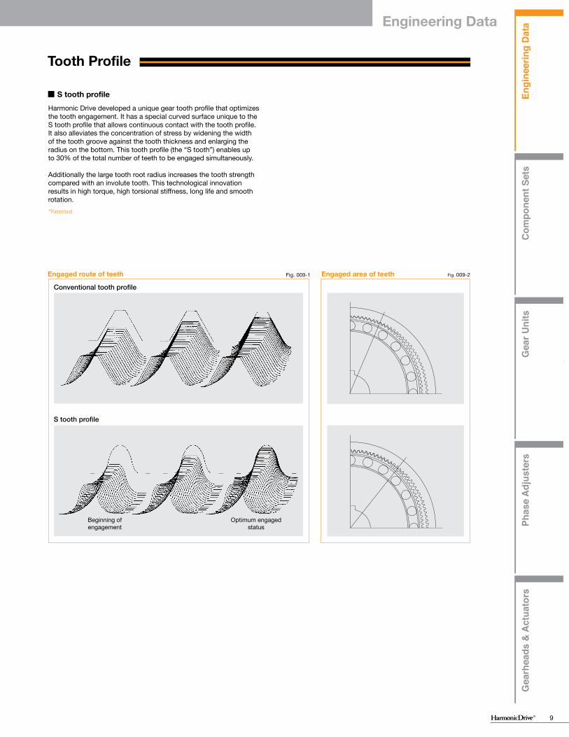
Harmonic Drive developed a unique gear tooth profile that optimizes the tooth engagement. It has a special curved surface unique to the S tooth profile that allows continuous contact with the tooth profile. It also alleviates the concentration of stress by widening the width of the tooth groove against the tooth thickness and enlarging the radius on the bottom. This tooth profile (the “S tooth”) enables up to 30% of the total number of teeth to be engaged simultaneously.
Additionally the large tooth root radius increases the tooth strength compared with an involute tooth. This technological innovation results in high torque, high torsional stiffness, long life and smooth rotation.
■ S tooth profile
*Patented
Fig. 009-1 Fig. 009-2Engaged area of teethEngaged route of teeth
Conventional tooth profile
S tooth profile
Beginning of engagement
Optimum engaged status
Engi
neer
ing
Dat
aC
ompo
nent
Set
sG
ear U
nits
Phas
e A
djus
ters
Gea
rhea
ds &
Act
uato
rs
Engi
neer
ing
Dat
aC
ompo
nent
Set
sG
ear U
nits
Phas
e A
djus
ters
Gea
rhea
ds &
Act
uato
rs
9
Engineering Data
Engi
neer
ing
Dat
aC
ompo
nent
Set
sG
ear U
nits
Phas
e A
djus
ters
Gea
rhea
ds &
Act
uato
rs
Grease lubricantPrecautions on using Harmonic Grease® 4B No.2
Oil lubricantLubricant for special environments
Tooth profile S tooth profile
Rotational direction and reduction ratio
Rating table definitions
Life
Torque limits
Product sizing and selection
Cup style
Lubrication
Silk hat style
Pancake style
Engineering Data
Starting torque
Backdriving torque
No-load running torque
Efficiency
Design guidelines
Assembly guidelines
Checking output bearing
Torsional stiffness
Vibration
Positional accuracy
Design guideline
Sealing
Checking procedureHow to calculate the maximum moment load
How to calculate the radial load coefficient (X) and axial load coefficient (Y)
How to calculate the average load
How to calculate life
How to calculate the static safety coefficient
How to calculate the life under oscillating movement
Assembly Precautions
"dedoidal" state
Bearing support of the input and output shafts
Wave Generator
Engineering Data
009010010011012012013014016018018019020021021022022023023024025026028028029030030031031032033034
Tooth Profile
Harmonic Drive developed a unique gear tooth profile that optimizes the tooth engagement. It has a special curved surface unique to the S tooth profile that allows continuous contact with the tooth profile. It also alleviates the concentration of stress by widening the width of the tooth groove against the tooth thickness and enlarging the radius on the bottom. This tooth profile (the “S tooth”) enables up to 30% of the total number of teeth to be engaged simultaneously.
Additionally the large tooth root radius increases the tooth strength compared with an involute tooth. This technological innovation results in high torque, high torsional stiffness, long life and smooth rotation.
■ S tooth profile
*Patented
Fig. 009-1 Fig. 009-2Engaged area of teethEngaged route of teeth
Conventional tooth profile
S tooth profile
Beginning of engagement
Optimum engaged status
Engi
neer
ing
Dat
aC
ompo
nent
Set
sG
ear U
nits
Phas
e A
djus
ters
Gea
rhea
ds &
Act
uato
rs
Grease lubricantPrecautions on using Harmonic Grease® 4B No.2
Oil lubricantLubricant for special environments
Tooth profile S tooth profile
Rotational direction and reduction ratio
Rating table definitions
Life
Torque limits
Product sizing and selection
Cup style
Lubrication
Silk hat style
Pancake style
Engineering Data
Starting torque
Backdriving torque
No-load running torque
Efficiency
Design guidelines
Assembly guidelines
Checking output bearing
Torsional stiffness
Vibration
Positional accuracy
Design guideline
Sealing
Checking procedureHow to calculate the maximum moment load
How to calculate the radial load coefficient (X) and axial load coefficient (Y)
How to calculate the average load
How to calculate life
How to calculate the static safety coefficient
How to calculate the life under oscillating movement
Assembly Precautions
"dedoidal" state
Bearing support of the input and output shafts
Wave Generator
Engineering Data
009010010011012012013014016018018019020021021022022023023024025026028028029030030031031032033034
Tooth Profile
Harmonic Drive developed a unique gear tooth profile that optimizes the tooth engagement. It has a special curved surface unique to the S tooth profile that allows continuous contact with the tooth profile. It also alleviates the concentration of stress by widening the width of the tooth groove against the tooth thickness and enlarging the radius on the bottom. This tooth profile (the “S tooth”) enables up to 30% of the total number of teeth to be engaged simultaneously.
Additionally the large tooth root radius increases the tooth strength compared with an involute tooth. This technological innovation results in high torque, high torsional stiffness, long life and smooth rotation.
■ S tooth profile
*Patented
Fig. 009-1 Fig. 009-2Engaged area of teethEngaged route of teeth
Conventional tooth profile
S tooth profile
Beginning of engagement
Optimum engaged status

Engi
neer
ing
Dat
aC
ompo
nent
Set
sG
ear U
nits
Phas
e A
djus
ters
Gea
rhea
ds &
Act
uato
rs
Engi
neer
ing
Dat
aC
ompo
nent
Set
sG
ear U
nits
Phas
e A
djus
ters
Gea
rhea
ds &
Act
uato
rs
10
1
i=ー−1R
4
i=ーR+1R
2
i=ー1R+1
3
i=ーRR+1
5
i=−R
6
i=R+1
7
1
i=ー−1R
4
i=ーR+1R
2
i=ー1R+1
3
i=ーRR+1
5
i=−R
6
i=R+1
7
FSCSCS
WG
Rotational direction and reduction ratio
Cup StyleSeries: CSG, CSF, CSD, CSF-mini
■ Rotational direction
Series: FB and FR
■ Rotational direction
* R indicates the reduction ratio value from the ratings table.
Input Output(Note) Contact us if you use the product
as Accelerator (5) and (6).
Input: Wave Generator (WG) Output: Flexspline (FS) Fixed: Circular Spline (CS)
(1) Reducer
Input: Circular Spline Output: Flexspline Fixed: Wave Generator
(4) OverdriveInput: Flexspline Output: Wave GeneratorFixed: Circular Spline
(5) OverdriveInput: Circular Spline Output: Wave Generator Fixed: Flexspline
(6) OverdriveWhen all of the wave generator, the flexspline and the circular spline rotate, combinations (1) through (6) are available.
(7) Differential
Input: Wave Generator Output: Circular SplineFixed: Flexspline
(2) ReducerInput: Flexspline Output: Circular Spline Fixed: Wave Generator
(3) Reducer
Fig. 010-1
Series: SHG, SHF, SHD
Silk hat
* R indicates the reduction ratio value from the ratings. table
Input Output(Note) Contact us if you use the product
as an overdrive of (5) or (6).
Input: Wave Generator Output: Flexspline Fixed: Circular Spline
(1) Reducer
Input: Circular Spline Output: Flexspline Fixed: Wave Generator
(4) OverdriveInput: Flexspline Output: Wave GeneratorFixed: Circular Spline
(5) OverdriveInput: Circular Spline Output: Wave Generator Fixed: Flexspline
(6) OverdriveWhen all of the wave generator, the flexspline and the circular spline rotate, Combinations (1) through (6) are available.
(7) Differential
Input: Wave Generator Output: Circular SplineFixed: Flexspline
(2) ReducerInput: Flexspline Output: Circular Spline Fixed: Wave Generator
(3) Reducer
Fig. 010-2
Reduction ratio
Reduction ratio
Reduction ratio
Reduction ratio
Number of teeth of the Flexspline: ZfNumber of teeth of the Circular Spline: Zc
Input: Wave GeneratorOutput: FlexsplineFixed: Circular Spline
Input: Wave GeneratorOutput: Circular SplineFixed: Flexspline
■ R1 indicates the reduction ratio value from the ratings table.
1R 1
Zf-ZcZf
1R 2
Zc-ZfZc
i1 = =
i2 = =
Number of teeth of the Flexspline: 200Number of teeth of the Circular Spline: 202
Input: Wave GeneratorOutput: FlexsplineFixed: Circular Spline
Input: Wave GeneratorOutput: Circular SplineFixed: Flexspline
i1 = = =
i2 = = =
1R 1
-1100
1R 2
1101
200-202200
202-200202
Example
The reduction ratio is determined by the number of teeth of the Flexspline and the Circular Spline
■ Reduction ratio
Pancake
■ Rotational direction
1
i=ー−1R
4
i=ーR+1R
2
i=ー1R+1
3
i=ーRR+1
5
i=R+1
6
i=−R
7
Fig. 11-1
Input OutputInputOutput
InputOutputInput Output Input Output
InputOutput InputOutput
(Note) Contact us if you use the product as Accelerator (5) and (6).
Input: Wave Generator Output: Circular Spline DFixed: Circular Spline S
(1) Reducer
When all of the Wave Generator, the Circular Spline S and the Circular Spline D rotate, Combinations (1) through (6) are available.
(7) Differential
Input: Wave Generator Output: Circular Spline SFixed: Circular Spline D
(2) ReducerInput: Circular Spline DOutput: Circular Spline SFixed: Wave Generator
(3) Reducer
Input: Circular Spline S Output: Circular Spline D Fixed: Wave Generator
(4) OverdriveInput: Circular Spline SOutput: Wave GeneratorFixed: Circular Spline D
(5) OverdriveInput: Circular Spline DOutput: Wave Generator Fixed: Circular Spline S
(6) Overdrive
Engineering Data

Engi
neer
ing
Dat
aC
ompo
nent
Set
sG
ear U
nits
Phas
e A
djus
ters
Gea
rhea
ds &
Act
uato
rs
Engi
neer
ing
Dat
aC
ompo
nent
Set
sG
ear U
nits
Phas
e A
djus
ters
Gea
rhea
ds &
Act
uato
rs
11
1
i=ー−1R
4
i=ーR+1R
2
i=ー1R+1
3
i=ーRR+1
5
i=−R
6
i=R+1
7
1
i=ー−1R
4
i=ーR+1R
2
i=ー1R+1
3
i=ーRR+1
5
i=−R
6
i=R+1
7
FSCSCS
WG
Rotational direction and reduction ratio
Cup StyleSeries: CSG, CSF, CSD, CSF-mini
■ Rotational direction
Series: FB and FR
■ Rotational direction
* R indicates the reduction ratio value from the ratings table.
Input Output(Note) Contact us if you use the product
as Accelerator (5) and (6).
Input: Wave Generator (WG) Output: Flexspline (FS) Fixed: Circular Spline (CS)
(1) Reducer
Input: Circular Spline Output: Flexspline Fixed: Wave Generator
(4) OverdriveInput: Flexspline Output: Wave GeneratorFixed: Circular Spline
(5) OverdriveInput: Circular Spline Output: Wave Generator Fixed: Flexspline
(6) OverdriveWhen all of the wave generator, the flexspline and the circular spline rotate, combinations (1) through (6) are available.
(7) Differential
Input: Wave Generator Output: Circular SplineFixed: Flexspline
(2) ReducerInput: Flexspline Output: Circular Spline Fixed: Wave Generator
(3) Reducer
Fig. 010-1
Series: SHG, SHF, SHD
Silk hat
* R indicates the reduction ratio value from the ratings. table
Input Output(Note) Contact us if you use the product
as an overdrive of (5) or (6).
Input: Wave Generator Output: Flexspline Fixed: Circular Spline
(1) Reducer
Input: Circular Spline Output: Flexspline Fixed: Wave Generator
(4) OverdriveInput: Flexspline Output: Wave GeneratorFixed: Circular Spline
(5) OverdriveInput: Circular Spline Output: Wave Generator Fixed: Flexspline
(6) OverdriveWhen all of the wave generator, the flexspline and the circular spline rotate, Combinations (1) through (6) are available.
(7) Differential
Input: Wave Generator Output: Circular SplineFixed: Flexspline
(2) ReducerInput: Flexspline Output: Circular Spline Fixed: Wave Generator
(3) Reducer
Fig. 010-2
Reduction ratio
Reduction ratio
Reduction ratio
Reduction ratio
Number of teeth of the Flexspline: ZfNumber of teeth of the Circular Spline: Zc
Input: Wave GeneratorOutput: FlexsplineFixed: Circular Spline
Input: Wave GeneratorOutput: Circular SplineFixed: Flexspline
■ R1 indicates the reduction ratio value from the ratings table.
1R 1
Zf-ZcZf
1R 2
Zc-ZfZc
i1 = =
i2 = =
Number of teeth of the Flexspline: 200Number of teeth of the Circular Spline: 202
Input: Wave GeneratorOutput: FlexsplineFixed: Circular Spline
Input: Wave GeneratorOutput: Circular SplineFixed: Flexspline
i1 = = =
i2 = = =
1R 1
-1100
1R 2
1101
200-202200
202-200202
Example
The reduction ratio is determined by the number of teeth of the Flexspline and the Circular Spline
■ Reduction ratio
Pancake
■ Rotational direction
1
i=ー−1R
4
i=ーR+1R
2
i=ー1R+1
3
i=ーRR+1
5
i=R+1
6
i=−R
7
Fig. 11-1
Input OutputInputOutput
InputOutputInput Output Input Output
InputOutput InputOutput
(Note) Contact us if you use the product as Accelerator (5) and (6).
Input: Wave Generator Output: Circular Spline DFixed: Circular Spline S
(1) Reducer
When all of the Wave Generator, the Circular Spline S and the Circular Spline D rotate, Combinations (1) through (6) are available.
(7) Differential
Input: Wave Generator Output: Circular Spline SFixed: Circular Spline D
(2) ReducerInput: Circular Spline DOutput: Circular Spline SFixed: Wave Generator
(3) Reducer
Input: Circular Spline S Output: Circular Spline D Fixed: Wave Generator
(4) OverdriveInput: Circular Spline SOutput: Wave GeneratorFixed: Circular Spline D
(5) OverdriveInput: Circular Spline DOutput: Wave Generator Fixed: Circular Spline S
(6) Overdrive
Engineering Data

Engi
neer
ing
Dat
aC
ompo
nent
Set
sG
ear U
nits
Phas
e A
djus
ters
Gea
rhea
ds &
Act
uato
rs
Engi
neer
ing
Dat
aC
ompo
nent
Set
sG
ear U
nits
Phas
e A
djus
ters
Gea
rhea
ds &
Act
uato
rs
12
→
→
Life
Graph 012-1
Graph 012-2Relative torque rating
Example of application motion profile
+
−
+
−
Start
(Speed cycle)
Load
torq
ue
Start
Stop
Steady
Time
Time
Wav
e G
ener
ator
rota
tiona
l spe
ed
Mom
enta
ry P
eak
Torq
ue
Load
Tor
que
Repe
ated
Pea
k To
rque
Abnormal impact torque
Table 012-1
Formula 012-1
Table 012-2
Rating Table Definitions Torque LimitsSee the corresponding pages of each series for values.
■ Rated torqueRated torque indicates allowable continuous load torque at rated input speed.
■ Moment of Inertia The rating indicates the moment of inertia reflected to the gear input.
■ Maximum Average Input Speed Maximum Input Speed Do not exceed the allowable rating. (calculation formula of the average input speed: Page 14).
■ Limit for Repeated Peak Torque (see Graph 12-1)
During acceleration and deceleration the Harmonic Drive® gear experiences a peak torque as a result of the moment of inertia of the output load. The table indicates the limit for repeated peak torque.
■ Limit for Momentary Peak Torque (see Graph 12-1)
The gear may be subjected to momentary peak torques in the event of a collision or emergency stop. The magnitude and frequency of occurrence of such peak torques must be kept to a minimum and they should, under no circumstance, occur during normal operating cycle. The allowable number of occurrences of the momentary peak torque may be calculated by using formula 13-1.
■ Limit for Average TorqueIn cases where load torque and input speed vary, it is necessary to calculate an average value of load torque. The table indicates the limit for average torque. The average torque calculated must not exceed this limit. (calculation formula: Page 14)
■ Life of the wave generatorThe life of a gear is determined by the life of the wavegenerator bearing. The life may be calculated by using theinput speed and the output load torque.
Life
Calculation formula for Rated Lifetime
Lh=Ln ・ ・ TavTr 3
NavNr
LnTrNr
TavNav
CSF, CSD, SHF, SHD, CSF-mini
7,000 hours35,000 hours
CSG, SHG
10,000 hours50,000 hours
Series name
L10 L50 (average life)
Life of L10 or L50 Rated torqueRated input speedAverage load torque on the output side (calculation formula: Page 14)Average input speed (calculation formula: Page 14)
* Life is based on the input speed and output load torque from the rating table.
* Lubricant life not taken into consideration in the graph described above.* Use the graph above as reference values.
105 106 107 108 109 1010
0
1
2
3
4
5
6
7
8
9
10
16
17Buckling torque
Racheting torque
Fatigue strength of the flexspline
Repeated peak torque
Rated torque
Life of wave generator (L10)
Momentary peak torque
Load
torq
ue (w
hen
the
rate
d to
rque
is 1
)
Total number of input rotations
Formula 013-1
Figure 013-1
N= 1.0×10⁴
2× ×tn60
Caution
N occurancest secn rpm
Allowable occurancesTime that impact torque is appliedRotational speed of the wave generator
The flexspline bends two times per one revolution of the wave generator.
If the number of occurances is exceeded, the Flexspline may experience a fatigue failure.
Calculation formula
Warning
When the flexspline buckles, early failure of the HarmonicDrive® gear will occur.
When a highly excessive torque (16 to 17 times rated torque) is applied to the output with the input stationary, the flexspline may experience plastic deformation. This is defined as buckling torque.
■ Buckling torque
* See the corresponding pages of each series for buckling torque values.
The Flexspline is subjected to repeated deflections, and its strength determines the torque capacity of the Harmonic Drive® gear. The values given for Rated Torque at Rated Speed and for the allowable Repeated Peak Torque are based on an infinite fatiguelife for the Flexspline. The torque that occurs during a collision must be below the momentary peak torque (impact torque). The maximum number of occurrences is given by the equation below.
■ Strength of flexspline
Allowable limit of the bending cycles of the flexspline during rotation of the wave generator while the impact torque is applied: 1.0 x 10⁴ (cycles)
The torque that occurs during a collision must be below the momentary peak torque (impact torque). The maximum numberof occurrences is given by the equation below.
When excessive torque (8 to 9 times rated torque) is applied while the gear is in motion, the teeth between the Circular Spline and Flexspline may not engage properly.This phenomenon is called ratcheting and the torque at whichthis occurs is called ratcheting torque. Ratcheting may cause theFlexspline to become non-concentric with the Circular Spline. Operating in this condition may result in shortened life and a Flexspline fatigue failure. * See the corresponding pages of each series for ratcheting torque values.* Ratcheting torque is affected by the stiffness of the housing to be used when
installing the circular spline. Contact us for details of the ratcheting torque.
■ Ratcheting torque
Caution
Caution
When ratcheting occurs, the teeth may not be correctly engaged and become out of alignment as shown in Figure 013-1. Operating the drive in this condition will cause vibration and damage the flexspline.
Once ratcheting occurs, the teeth wear excessively and the ratcheting torque may be lowered.
Circular Spline
"Dedoidal" condition.
Flexspline
Engineering Data

Engi
neer
ing
Dat
aC
ompo
nent
Set
sG
ear U
nits
Phas
e A
djus
ters
Gea
rhea
ds &
Act
uato
rs
Engi
neer
ing
Dat
aC
ompo
nent
Set
sG
ear U
nits
Phas
e A
djus
ters
Gea
rhea
ds &
Act
uato
rs
13
→
→
Life
Graph 012-1
Graph 012-2Relative torque rating
Example of application motion profile
+
−
+
−
Start
(Speed cycle)
Load
torq
ue
Start
Stop
Steady
Time
Time
Wav
e G
ener
ator
rota
tiona
l spe
ed
Mom
enta
ry P
eak
Torq
ue
Load
Tor
que
Repe
ated
Pea
k To
rque
Abnormal impact torque
Table 012-1
Formula 012-1
Table 012-2
Rating Table Definitions Torque LimitsSee the corresponding pages of each series for values.
■ Rated torqueRated torque indicates allowable continuous load torque at rated input speed.
■ Moment of Inertia The rating indicates the moment of inertia reflected to the gear input.
■ Maximum Average Input Speed Maximum Input Speed Do not exceed the allowable rating. (calculation formula of the average input speed: Page 14).
■ Limit for Repeated Peak Torque (see Graph 12-1)
During acceleration and deceleration the Harmonic Drive® gear experiences a peak torque as a result of the moment of inertia of the output load. The table indicates the limit for repeated peak torque.
■ Limit for Momentary Peak Torque (see Graph 12-1)
The gear may be subjected to momentary peak torques in the event of a collision or emergency stop. The magnitude and frequency of occurrence of such peak torques must be kept to a minimum and they should, under no circumstance, occur during normal operating cycle. The allowable number of occurrences of the momentary peak torque may be calculated by using formula 13-1.
■ Limit for Average TorqueIn cases where load torque and input speed vary, it is necessary to calculate an average value of load torque. The table indicates the limit for average torque. The average torque calculated must not exceed this limit. (calculation formula: Page 14)
■ Life of the wave generatorThe life of a gear is determined by the life of the wavegenerator bearing. The life may be calculated by using theinput speed and the output load torque.
Life
Calculation formula for Rated Lifetime
Lh=Ln ・ ・ TavTr 3
NavNr
LnTrNr
TavNav
CSF, CSD, SHF, SHD, CSF-mini
7,000 hours35,000 hours
CSG, SHG
10,000 hours50,000 hours
Series name
L10 L50 (average life)
Life of L10 or L50 Rated torqueRated input speedAverage load torque on the output side (calculation formula: Page 14)Average input speed (calculation formula: Page 14)
* Life is based on the input speed and output load torque from the rating table.
* Lubricant life not taken into consideration in the graph described above.* Use the graph above as reference values.
105 106 107 108 109 1010
0
1
2
3
4
5
6
7
8
9
10
16
17Buckling torque
Racheting torque
Fatigue strength of the flexspline
Repeated peak torque
Rated torque
Life of wave generator (L10)
Momentary peak torque
Load
torq
ue (w
hen
the
rate
d to
rque
is 1
)
Total number of input rotations
Formula 013-1
Figure 013-1
N= 1.0×10⁴
2× ×tn60
Caution
N occurancest secn rpm
Allowable occurancesTime that impact torque is appliedRotational speed of the wave generator
The flexspline bends two times per one revolution of the wave generator.
If the number of occurances is exceeded, the Flexspline may experience a fatigue failure.
Calculation formula
Warning
When the flexspline buckles, early failure of the HarmonicDrive® gear will occur.
When a highly excessive torque (16 to 17 times rated torque) is applied to the output with the input stationary, the flexspline may experience plastic deformation. This is defined as buckling torque.
■ Buckling torque
* See the corresponding pages of each series for buckling torque values.
The Flexspline is subjected to repeated deflections, and its strength determines the torque capacity of the Harmonic Drive® gear. The values given for Rated Torque at Rated Speed and for the allowable Repeated Peak Torque are based on an infinite fatiguelife for the Flexspline. The torque that occurs during a collision must be below the momentary peak torque (impact torque). The maximum number of occurrences is given by the equation below.
■ Strength of flexspline
Allowable limit of the bending cycles of the flexspline during rotation of the wave generator while the impact torque is applied: 1.0 x 10⁴ (cycles)
The torque that occurs during a collision must be below the momentary peak torque (impact torque). The maximum numberof occurrences is given by the equation below.
When excessive torque (8 to 9 times rated torque) is applied while the gear is in motion, the teeth between the Circular Spline and Flexspline may not engage properly.This phenomenon is called ratcheting and the torque at whichthis occurs is called ratcheting torque. Ratcheting may cause theFlexspline to become non-concentric with the Circular Spline. Operating in this condition may result in shortened life and a Flexspline fatigue failure. * See the corresponding pages of each series for ratcheting torque values.* Ratcheting torque is affected by the stiffness of the housing to be used when
installing the circular spline. Contact us for details of the ratcheting torque.
■ Ratcheting torque
Caution
Caution
When ratcheting occurs, the teeth may not be correctly engaged and become out of alignment as shown in Figure 013-1. Operating the drive in this condition will cause vibration and damage the flexspline.
Once ratcheting occurs, the teeth wear excessively and the ratcheting torque may be lowered.
Circular Spline
"Dedoidal" condition.
Flexspline
Engineering Data

Engi
neer
ing
Dat
aC
ompo
nent
Set
sG
ear U
nits
Phas
e A
djus
ters
Gea
rhea
ds &
Act
uato
rs
Engi
neer
ing
Dat
aC
ompo
nent
Set
sG
ear U
nits
Phas
e A
djus
ters
Gea
rhea
ds &
Act
uato
rs
14
Product Sizing & Selection
NG
NG
NG
NG
NG
OK
OK
OK
OK
OK
In general, a servo system rarely operates at a continuous load and speed. The input rotational speed, load torque change and comparatively large torque are applied at start and stop. Unexpected impact torque may be applied.These fluctuating load torques should be converted to the average load torque when selecting a model number.As an accurate cross roller bearing is built in the direct external load support (output flange), the maximum moment load, life of the cross roller bearing and the static safety coefficient should also be checked.
+
ー
T 1
T 2
T 3
T 4
T n
t 1 t 2 t 3 t 4 t n
n 1
n 2
n 3
n 4
n n
Graph 14-1
OK
OK
OK
OK
OK
NG
NG
NG
NG
NG
■ Example of model number selection
Review the application motion profile. Check the specifications shown in the figure below.
■ Checking the application motion profile
Time
Time* n1, n2 and nn indicate the average values.
Load
torq
ueO
utpu
t rot
atio
nal
spee
d
Obtain the value of each application motion profile.Load torque Tn (Nm)Time tn (sec)Output rotational speed nn (rpm)
Maximum rotational speedMax. output speed no maxMax. input rotational speed ni max(Restricted by motors)
Emergency stop torqueWhen impact torque is applied Ts, ts, ns
Required life L10 = L (hours)
Normal operation patternStarting (acceleration) T1, t1, n1
Steady operation (constant velocity) T2, t2, n2
Stopping (deceleration) T3, t3, n3
Dwell T4, t4, n4
Calculate the average load torque applied on the output side from the application motion profile: Tav (Nm).
Make a preliminary model selection with the following conditions. Tav ≦ Limit for average torque torque
(See the rating table of each series).
n 1 ・t
1 +n 2 ・t
2 +・・・n n ・t
n
t 1 + t
2 +・・・ t n
no av = ————————————————
ni maxno max——————≧ R
ni av = no av・R
ni max = no max・R
Calculate the average output speed: no av (rpm)
Obtain the reduction ratio (R). A limit is placed on “ni max” by motors.
Calculate the average input rotational speed from the average output rotational speed (no av) and the reduction ratio (R): ni av (rpm)
Calculate the maximum input rotational speed from the max. output rotational speed (no max) and the reduction ratio (R): ni max (rpm)
Tav =3 n 1 ・t 1 ・|T 1 |3+n 2 ・t 2 ・|T 2 |3+・・・n n ・t n ・|T n |3
n 1 ・t 1 +n 2 ・t 2 +・・・n n ・t n
Check whether the preliminary model number satisfies the following condition from the rating table.
Ni av ≦ Limit for average speed (rpm)
Ni max ≦ Limit for maximum speed (rpm)
104
n S ・R
N S =————— ・・・・・・N
S ≦ 1.0×10⁴ 2・————・t
60
L10 = 7000・( ——— ) ・ ( ——— ) (hours)Tav ni avTr nr3
Check whether T1 and T3 are less than the repeated peak torque specification.
Check whether Ts is less than the the momentary peak torque specification.
Check whether the calculated life is equal to or more than the life of the wave generator (see Page 13).
Calculate (Ns) the allowable number of rotations during impact torque.
Calculate the lifetime.
The model number is confirmed.
Maximum rotational speedMax. output speed no max = 14 rpmMax. input speed ni max = 1800 rpm(Restricted by motors)
Emergency stop torqueWhen impact torque is applied Ts = 500 Nm, ts = 0.15 sec,
ns = 14 rpm Required life L10 = 7000 (hours)
Value of each application motion profileLoad torqueTimeOutput speed
Normal operation patternStarting (acceleration) T1 = 400 Nm, t1 = 0.3sec, n1 = 7rpmSteady operation (constant velocity) T2 = 320 Nm, t2 = 3sec, n2 = 14rpmStopping (deceleration) T3 = 200 Nm, t3 = 0.4sec, n3 = 7rpmDwell T4 = 0 Nm, t4 = 0.2 sec, n4 = 0 rpm
Tn(Nm)tn(sec)nn(rpm)
Revi
ew th
e op
erat
ion
cond
ition
s, s
ize a
nd re
duct
ion
ratio
Please use the flowchart shown below for selecting a size.Operating conditions must not exceed the performanceratings.
■ Flowchart for selecting a size
Revi
ew th
e op
erat
ion
cond
ition
s an
d m
odel
num
ber
Calculate the average load torque to the output side based on the application motion profile: Tav (Nm).
7 rpm・0.3 sec・|400Nm|3+14 rpm・3 sec・|320Nm|3+7 rpm・0.4 sec・|200Nm|3 3 Tav = 7 rpm・0.3 sec+14 rpm・3 sec+7 rpm・0.4 sec
7 rpm・0.3 sec+14 rpm・3 sec+7 rpm・0.4 sec0.3 sec + 3 sec + 0.4 sec + 0.2 secno av = ———————————————————————————— = 12 rpm
1800 rpm14 rpm——————— = 128.6 ≧ 120
ni av = 12 rpm・120 = 1440 rpm
ni max = 14 rpm・120 = 1680 rpm
Calculate the average output rotational speed: no av (rpm)
Calculate the average input rotational speed from the average output rotational speed (no av) and the reduction ratio (R): ni av (rpm)Calculate the maximum input rotational speed from the maximum output rotational speed (no max) and the reduction ratio (R): ni max (rpm)
Obtain the reduction ratio (R).
Check whether the preliminary selected model number satisfies the following condition from the rating table.
Ni av = 1440 rpm ≦ 3600 rpm (Max average input speed of size 40)Ni max = 1680 rpm ≦ 5600 rpm (Max input speed of size 40)
Make a preliminary model selection with the following conditions. Tav = 319 Nm ≦ 620 Nm (Limit for average torque for model number CSF-40-120-2A-GR: See the rating table on Page 39.)Thus, CSF-40-120-2A-GR is tentatively selected.
104
14 rpm・120N
S =————————= 1190 ≦ 1.0×10⁴ 2・————————・0.15 sec
60
L10 = 7000・( —————— ) ・ ( ————————— ) (hours)319 Nm 1440 rpm294 Nm 2000 rpm3
Check whether T1 and T3 are equal to or less than the repeated peak torque specification. T1 = 400 Nm ≦ 617 Nm (Limit of repeated peak torque of size 40)
T3 = 200 Nm ≦ 617 Nm (Limit of repeated peak torque of size 40)
Check whether Ts is equal to or less than the momentary peak torque specification. Ts = 500 Nm ≦ 1180 Nm (Limit for momentary torque of size 40)
Calculate the allowable number (Ns) rotation during impact torque and confirm ≦ 1.0×10⁴
Check whether the calculated life is equal to or more than the life of the wave generator (see Page 12).L10 =7610 hours ≧ 7000 (life of the wave generator: L10)
The selection of model number CSF-40-120-2A-GR is confirmed from the above calculations.
Calculate the lifetime.
Engineering Data

Engi
neer
ing
Dat
aC
ompo
nent
Set
sG
ear U
nits
Phas
e A
djus
ters
Gea
rhea
ds &
Act
uato
rs
Engi
neer
ing
Dat
aC
ompo
nent
Set
sG
ear U
nits
Phas
e A
djus
ters
Gea
rhea
ds &
Act
uato
rs
15
Product Sizing & Selection
NG
NG
NG
NG
NG
OK
OK
OK
OK
OK
In general, a servo system rarely operates at a continuous load and speed. The input rotational speed, load torque change and comparatively large torque are applied at start and stop. Unexpected impact torque may be applied.These fluctuating load torques should be converted to the average load torque when selecting a model number.As an accurate cross roller bearing is built in the direct external load support (output flange), the maximum moment load, life of the cross roller bearing and the static safety coefficient should also be checked.
+
ー
T 1
T 2
T 3
T 4
T n
t 1 t 2 t 3 t 4 t n
n 1
n 2
n 3
n 4
n n
Graph 14-1
OK
OK
OK
OK
OK
NG
NG
NG
NG
NG
■ Example of model number selection
Review the application motion profile. Check the specifications shown in the figure below.
■ Checking the application motion profile
Time
Time* n1, n2 and nn indicate the average values.
Load
torq
ueO
utpu
t rot
atio
nal
spee
d
Obtain the value of each application motion profile.Load torque Tn (Nm)Time tn (sec)Output rotational speed nn (rpm)
Maximum rotational speedMax. output speed no maxMax. input rotational speed ni max(Restricted by motors)
Emergency stop torqueWhen impact torque is applied Ts, ts, ns
Required life L10 = L (hours)
Normal operation patternStarting (acceleration) T1, t1, n1
Steady operation (constant velocity) T2, t2, n2
Stopping (deceleration) T3, t3, n3
Dwell T4, t4, n4
Calculate the average load torque applied on the output side from the application motion profile: Tav (Nm).
Make a preliminary model selection with the following conditions. Tav ≦ Limit for average torque torque
(See the rating table of each series).
n 1 ・t
1 +n 2 ・t
2 +・・・n n ・t
n
t 1 + t
2 +・・・ t n
no av = ————————————————
ni maxno max——————≧ R
ni av = no av・R
ni max = no max・R
Calculate the average output speed: no av (rpm)
Obtain the reduction ratio (R). A limit is placed on “ni max” by motors.
Calculate the average input rotational speed from the average output rotational speed (no av) and the reduction ratio (R): ni av (rpm)
Calculate the maximum input rotational speed from the max. output rotational speed (no max) and the reduction ratio (R): ni max (rpm)
Tav =3 n 1 ・t 1 ・|T 1 |3+n 2 ・t 2 ・|T 2 |3+・・・n n ・t n ・|T n |3
n 1 ・t 1 +n 2 ・t 2 +・・・n n ・t n
Check whether the preliminary model number satisfies the following condition from the rating table.
Ni av ≦ Limit for average speed (rpm)
Ni max ≦ Limit for maximum speed (rpm)
104
n S ・R
N S =————— ・・・・・・N
S ≦ 1.0×10⁴ 2・————・t
60
L10 = 7000・( ——— ) ・ ( ——— ) (hours)Tav ni avTr nr3
Check whether T1 and T3 are less than the repeated peak torque specification.
Check whether Ts is less than the the momentary peak torque specification.
Check whether the calculated life is equal to or more than the life of the wave generator (see Page 13).
Calculate (Ns) the allowable number of rotations during impact torque.
Calculate the lifetime.
The model number is confirmed.
Maximum rotational speedMax. output speed no max = 14 rpmMax. input speed ni max = 1800 rpm(Restricted by motors)
Emergency stop torqueWhen impact torque is applied Ts = 500 Nm, ts = 0.15 sec,
ns = 14 rpm Required life L10 = 7000 (hours)
Value of each application motion profileLoad torqueTimeOutput speed
Normal operation patternStarting (acceleration) T1 = 400 Nm, t1 = 0.3sec, n1 = 7rpmSteady operation (constant velocity) T2 = 320 Nm, t2 = 3sec, n2 = 14rpmStopping (deceleration) T3 = 200 Nm, t3 = 0.4sec, n3 = 7rpmDwell T4 = 0 Nm, t4 = 0.2 sec, n4 = 0 rpm
Tn(Nm)tn(sec)nn(rpm)
Revi
ew th
e op
erat
ion
cond
ition
s, s
ize a
nd re
duct
ion
ratio
Please use the flowchart shown below for selecting a size.Operating conditions must not exceed the performanceratings.
■ Flowchart for selecting a size
Revi
ew th
e op
erat
ion
cond
ition
s an
d m
odel
num
ber
Calculate the average load torque to the output side based on the application motion profile: Tav (Nm).
7 rpm・0.3 sec・|400Nm|3+14 rpm・3 sec・|320Nm|3+7 rpm・0.4 sec・|200Nm|3 3 Tav = 7 rpm・0.3 sec+14 rpm・3 sec+7 rpm・0.4 sec
7 rpm・0.3 sec+14 rpm・3 sec+7 rpm・0.4 sec0.3 sec + 3 sec + 0.4 sec + 0.2 secno av = ———————————————————————————— = 12 rpm
1800 rpm14 rpm——————— = 128.6 ≧ 120
ni av = 12 rpm・120 = 1440 rpm
ni max = 14 rpm・120 = 1680 rpm
Calculate the average output rotational speed: no av (rpm)
Calculate the average input rotational speed from the average output rotational speed (no av) and the reduction ratio (R): ni av (rpm)Calculate the maximum input rotational speed from the maximum output rotational speed (no max) and the reduction ratio (R): ni max (rpm)
Obtain the reduction ratio (R).
Check whether the preliminary selected model number satisfies the following condition from the rating table.
Ni av = 1440 rpm ≦ 3600 rpm (Max average input speed of size 40)Ni max = 1680 rpm ≦ 5600 rpm (Max input speed of size 40)
Make a preliminary model selection with the following conditions. Tav = 319 Nm ≦ 620 Nm (Limit for average torque for model number CSF-40-120-2A-GR: See the rating table on Page 39.)Thus, CSF-40-120-2A-GR is tentatively selected.
104
14 rpm・120N
S =————————= 1190 ≦ 1.0×10⁴ 2・————————・0.15 sec
60
L10 = 7000・( —————— ) ・ ( ————————— ) (hours)319 Nm 1440 rpm294 Nm 2000 rpm3
Check whether T1 and T3 are equal to or less than the repeated peak torque specification. T1 = 400 Nm ≦ 617 Nm (Limit of repeated peak torque of size 40)
T3 = 200 Nm ≦ 617 Nm (Limit of repeated peak torque of size 40)
Check whether Ts is equal to or less than the momentary peak torque specification. Ts = 500 Nm ≦ 1180 Nm (Limit for momentary torque of size 40)
Calculate the allowable number (Ns) rotation during impact torque and confirm ≦ 1.0×10⁴
Check whether the calculated life is equal to or more than the life of the wave generator (see Page 12).L10 =7610 hours ≧ 7000 (life of the wave generator: L10)
The selection of model number CSF-40-120-2A-GR is confirmed from the above calculations.
Calculate the lifetime.
Engineering Data

Engi
neer
ing
Dat
aC
ompo
nent
Set
sG
ear U
nits
Phas
e A
djus
ters
Gea
rhea
ds &
Act
uato
rs
Engi
neer
ing
Dat
aC
ompo
nent
Set
sG
ear U
nits
Phas
e A
djus
ters
Gea
rhea
ds &
Act
uato
rs
16
11 14 17 20 25 32
SK-1ASK-2
4B No.2
-○△
-○△
-○△
-○△
○-□
○-□
○-□
118
8
14 17 20 25 32
SK-1ASK-2
4B No.2
-○-
-○-
-○□
-○□
○△□
○△□
○△□
40 45 50 58 65 80 10090
SK-1ASK-2
4BNo.2
○△□
○-□
○-□
○-□
○-□
○-□
○-□
○-□
SK-1A SK-2 4B No.2
○○△◎
○○△◎
SK-1A SK-2
◎◎◎△
4B No.2
LGT
LGTn
Tr
Tav
20 40 60 80 100 120
4B No.2
SK-1ASK-2
1010
109
108
107
LGT=LGTn × ––––––TavTr 3
LubricationComponent Sets: CSD-2A, CSF-2A, CSG-2A, FB-2, FB-0, FR-2, SHF-2A, SHG-2A and SHD and SHG/SHF -2SO and -2SH gear units:Grease lubricant and oil lubricant are available for lubricating the component sets and SHD gear unit. It is extremely important to properly grease your component sets and SHD gear unit. Proper lubrication is essential for high performance and reliability. Harmonic Drive® component sets are shipped with a rust- preventative oil. The characteristics of the lubricating grease and oil types approved by Harmonic Drive are not changed by mixing with the preservation oil. It is therefore not necessary to remove the preservation oil completely from the gear components. However, the mating surfaces must be degreased before the assembly.
Gear Units: CSG/CSF 2UH and 2UH-LW; CSD-2UF and -2UH; SHG/SHF-2UH and 2UH- LW; SHG/SHF-2UJ; CSF Supermini, CSF Mini, and CSF-2UP.Grease lubricant is standard for lubricating the gear units. You do not need to apply grease during assembly as the product is lubricated and shipped.See Page 19 for using lubricant beyond the temperature range in table 16-2.* Contact us if you want consistency zero (NLGI No.0) for maintenance reasons.
Name of lubricant Table 016-1
Table 016-2
Harmonic Grease® SK-1AHarmonic Grease® SK-2Harmonic Grease® 4B No.2Industrial gear oil class-2 (extreme pressure) ISO VG68
Grease
Oil
SK-1A 0ºC to + 40ºCSK-2 0ºC to + 40ºC4B No.2 –10ºC to + 70ºCISO VG68 0ºC to + 40ºC
Grease
Oil
Temperature
* The hottest section should not be more than 40° above the ambient temperature.
Note: The three basic components of the gear - the Flexspline, Wave Generator and Circular Spline - are matched and serialized in the factory. Depending on the product they are either greased or prepared with preservation oil. Then the individual components are assembled. If you receive several units, please be careful not to mix the matched components. This can be avoided by verifying that the serial numbers of the assembled gear components are identical.
Table 016-3
NLGI consistency No. Mixing consistency range
Grease lubricant■ Types of lubricantHarmonic Grease® SK-1AThis grease was developed for Harmonic Drive® gears and features good durability and efficiency.
Harmonic Grease® SK-2This grease was developed for small sized Harmonic Drive® gears and features smooth rotation of the Wave Generator since high pressure additive is liquefied.
Harmonic Grease® 4B No.2This has been developed exclusively for the CSF and CSG and features long life and can be used over a wide range of temperature.
(Note)1. Grease lubrication must have proper sealing, this is essential for 4B No.2. Rotating part: Oil seal with spring is needed. Mating part: O ring or seal adhesive is needed.
2. The grease has the highest deterioration rate in the region where the grease is subjected to the greatest shear (near wave generator).
Its viscosity is between JIS No.0 and No.00 depending on the operation.
Compatible grease varies depending on the size and reduction ratio. See the following compatibility table. We recommend SK-1A and SK-2 for general use.
■ Compatible grease by size
Table 016-5
Table 016-6
Ratios 30:1
Ratios 50:1* and above
Size
Size
Size
○: Standard grease△: Semi-standard grease□: Recommended grease for long life and high load* Oil lubrication is required for component-sets size 50 or larger with a reduction ratio of 50:1.
Table 016-4
Grease
Base oil Refined oil Refined oil Composite hydrocarbon oil
Thickening agent Lithium soap base
Lithium soap base Urea
Storage life 5 years in sealed condition
5 years in sealed condition
5 years in sealed condition
Additive Extreme-pressure additive, others
Extreme-pressure additive, others
Extreme-pressure additive, others
NLGI consistency No. No. 2 No. 2 No. 1.5
Base Viscosity cSt (25ºC) 265 to 295 265 to 295 290 to 320
Drop Point 197ºC 198ºC 247ºC
Appearance Yellow Green Light yellow
Grease specification Table 016-7Grease characteristics
Grease
DurabilityFretting resistanceLow-temperature performanceGrease leakage
Excellent ◎Good ○Use Caution △
:::
The wear characteristics of the gear are strongly influenced by thecondition of the grease lubrication. The condition of the grease isaffected by the ambient temperature. The graph 017-1 shows the maximum number of input rotations for various temperatures. This graph applies to applications where the average load torque does not exceed the rated torque.
Note: Recommended Grease: SK-1A or SK-2
■ When to replace grease
Calculation formula when the average load torque exceeds the rated torque Formula 017-1
Formula Symbols Table 017-1
Grease change (if average load torque exceeds rated torque)Grease change (if average load torque is equal to or less than rated torque) See the Graph 017-1.
See the "Ratings Table" of each series.Calculation formula: See Page 014.Average load torque
Rated torque
input revolutions
input revolutions
(From Graph)
Nm
Nm
When to replace grease: LGTn (when the average load torque is equal to or less than the rated torque) Graph 017-1
Num
ber o
f inp
ut ro
tatio
ns
Grease Life
Wave Generator Life
Grease temperature (oC)
■ Other precautions1. Avoid mixing different kinds of grease. The gear should be in an individual case when installed.
2. Please contact us when you use HarmonicDrive® gears at constant load or in one direction continuously, as it may cause lubrication problems.
3. Grease leakage. A sealed structure is needed to maintain the high durability of the gear and prevent grease leakage.
■ See the corresponding pages of the design guide of each series for “Recommended minimum housing clearance,” Application guide” and “Application quantity.”
355 to 385400 to 430
000
Engineering Data
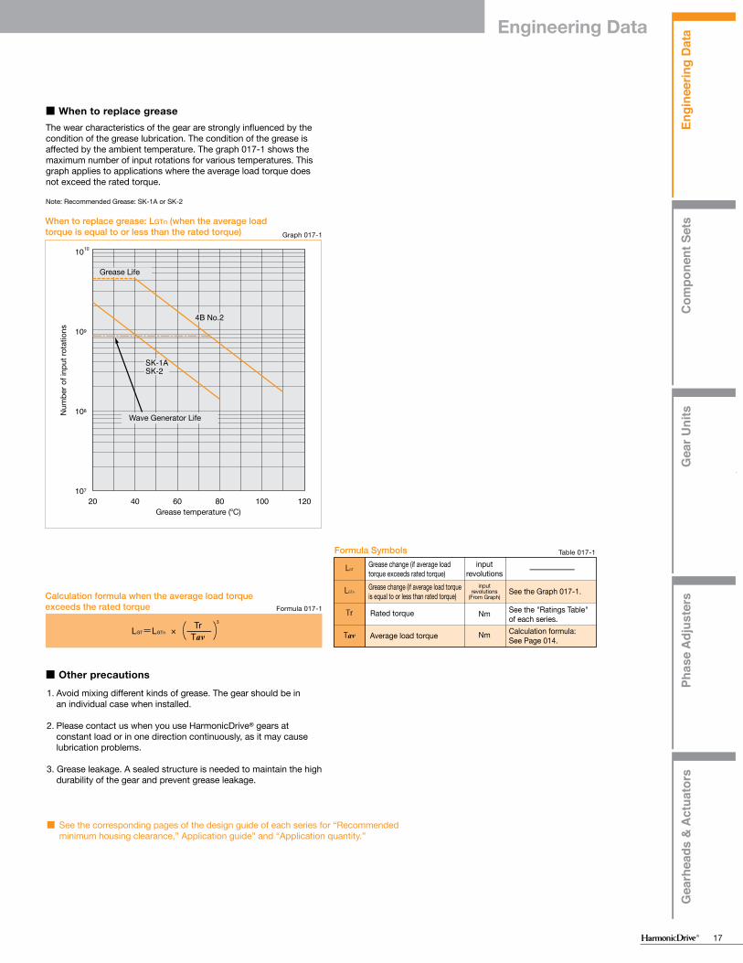
Engi
neer
ing
Dat
aC
ompo
nent
Set
sG
ear U
nits
Phas
e A
djus
ters
Gea
rhea
ds &
Act
uato
rs
Engi
neer
ing
Dat
aC
ompo
nent
Set
sG
ear U
nits
Phas
e A
djus
ters
Gea
rhea
ds &
Act
uato
rs
17
11 14 17 20 25 32
SK-1ASK-2
4B No.2
-○△
-○△
-○△
-○△
○-□
○-□
○-□
118
8
14 17 20 25 32
SK-1ASK-2
4B No.2
-○-
-○-
-○□
-○□
○△□
○△□
○△□
40 45 50 58 65 80 10090
SK-1ASK-2
4BNo.2
○△□
○-□
○-□
○-□
○-□
○-□
○-□
○-□
SK-1A SK-2 4B No.2
○○△◎
○○△◎
SK-1A SK-2
◎◎◎△
4B No.2
LGT
LGTn
Tr
Tav
20 40 60 80 100 120
4B No.2
SK-1ASK-2
1010
109
108
107
LGT=LGTn × ––––––TavTr 3
LubricationComponent Sets: CSD-2A, CSF-2A, CSG-2A, FB-2, FB-0, FR-2, SHF-2A, SHG-2A and SHD and SHG/SHF -2SO and -2SH gear units:Grease lubricant and oil lubricant are available for lubricating the component sets and SHD gear unit. It is extremely important to properly grease your component sets and SHD gear unit. Proper lubrication is essential for high performance and reliability. Harmonic Drive® component sets are shipped with a rust- preventative oil. The characteristics of the lubricating grease and oil types approved by Harmonic Drive are not changed by mixing with the preservation oil. It is therefore not necessary to remove the preservation oil completely from the gear components. However, the mating surfaces must be degreased before the assembly.
Gear Units: CSG/CSF 2UH and 2UH-LW; CSD-2UF and -2UH; SHG/SHF-2UH and 2UH- LW; SHG/SHF-2UJ; CSF Supermini, CSF Mini, and CSF-2UP.Grease lubricant is standard for lubricating the gear units. You do not need to apply grease during assembly as the product is lubricated and shipped.See Page 19 for using lubricant beyond the temperature range in table 16-2.* Contact us if you want consistency zero (NLGI No.0) for maintenance reasons.
Name of lubricant Table 016-1
Table 016-2
Harmonic Grease® SK-1AHarmonic Grease® SK-2Harmonic Grease® 4B No.2Industrial gear oil class-2 (extreme pressure) ISO VG68
Grease
Oil
SK-1A 0ºC to + 40ºCSK-2 0ºC to + 40ºC4B No.2 –10ºC to + 70ºCISO VG68 0ºC to + 40ºC
Grease
Oil
Temperature
* The hottest section should not be more than 40° above the ambient temperature.
Note: The three basic components of the gear - the Flexspline, Wave Generator and Circular Spline - are matched and serialized in the factory. Depending on the product they are either greased or prepared with preservation oil. Then the individual components are assembled. If you receive several units, please be careful not to mix the matched components. This can be avoided by verifying that the serial numbers of the assembled gear components are identical.
Table 016-3
NLGI consistency No. Mixing consistency range
Grease lubricant■ Types of lubricantHarmonic Grease® SK-1AThis grease was developed for Harmonic Drive® gears and features good durability and efficiency.
Harmonic Grease® SK-2This grease was developed for small sized Harmonic Drive® gears and features smooth rotation of the Wave Generator since high pressure additive is liquefied.
Harmonic Grease® 4B No.2This has been developed exclusively for the CSF and CSG and features long life and can be used over a wide range of temperature.
(Note)1. Grease lubrication must have proper sealing, this is essential for 4B No.2. Rotating part: Oil seal with spring is needed. Mating part: O ring or seal adhesive is needed.
2. The grease has the highest deterioration rate in the region where the grease is subjected to the greatest shear (near wave generator).
Its viscosity is between JIS No.0 and No.00 depending on the operation.
Compatible grease varies depending on the size and reduction ratio. See the following compatibility table. We recommend SK-1A and SK-2 for general use.
■ Compatible grease by size
Table 016-5
Table 016-6
Ratios 30:1
Ratios 50:1* and above
Size
Size
Size
○: Standard grease△: Semi-standard grease□: Recommended grease for long life and high load* Oil lubrication is required for component-sets size 50 or larger with a reduction ratio of 50:1.
Table 016-4
Grease
Base oil Refined oil Refined oil Composite hydrocarbon oil
Thickening agent Lithium soap base
Lithium soap base Urea
Storage life 5 years in sealed condition
5 years in sealed condition
5 years in sealed condition
Additive Extreme-pressure additive, others
Extreme-pressure additive, others
Extreme-pressure additive, others
NLGI consistency No. No. 2 No. 2 No. 1.5
Base Viscosity cSt (25ºC) 265 to 295 265 to 295 290 to 320
Drop Point 197ºC 198ºC 247ºC
Appearance Yellow Green Light yellow
Grease specification Table 016-7Grease characteristics
Grease
DurabilityFretting resistanceLow-temperature performanceGrease leakage
Excellent ◎Good ○Use Caution △
:::
The wear characteristics of the gear are strongly influenced by thecondition of the grease lubrication. The condition of the grease isaffected by the ambient temperature. The graph 017-1 shows the maximum number of input rotations for various temperatures. This graph applies to applications where the average load torque does not exceed the rated torque.
Note: Recommended Grease: SK-1A or SK-2
■ When to replace grease
Calculation formula when the average load torque exceeds the rated torque Formula 017-1
Formula Symbols Table 017-1
Grease change (if average load torque exceeds rated torque)Grease change (if average load torque is equal to or less than rated torque) See the Graph 017-1.
See the "Ratings Table" of each series.Calculation formula: See Page 014.Average load torque
Rated torque
input revolutions
input revolutions
(From Graph)
Nm
Nm
When to replace grease: LGTn (when the average load torque is equal to or less than the rated torque) Graph 017-1
Num
ber o
f inp
ut ro
tatio
ns
Grease Life
Wave Generator Life
Grease temperature (oC)
■ Other precautions1. Avoid mixing different kinds of grease. The gear should be in an individual case when installed.
2. Please contact us when you use HarmonicDrive® gears at constant load or in one direction continuously, as it may cause lubrication problems.
3. Grease leakage. A sealed structure is needed to maintain the high durability of the gear and prevent grease leakage.
■ See the corresponding pages of the design guide of each series for “Recommended minimum housing clearance,” Application guide” and “Application quantity.”
355 to 385400 to 430
000
Engineering Data

Engi
neer
ing
Dat
aC
ompo
nent
Set
sG
ear U
nits
Phas
e A
djus
ters
Gea
rhea
ds &
Act
uato
rs
Engi
neer
ing
Dat
aC
ompo
nent
Set
sG
ear U
nits
Phas
e A
djus
ters
Gea
rhea
ds &
Act
uato
rs
18
Precautions on using Harmonic Grease® 4B No.2
Harmonic Grease® 4B No.2 lubrication is ideally suited for Harmonic Drive® gears. (1) Apply the grease to each contacting joint at the beginning of operation.(2) Remove any contaminents created by abrasion during running-in period.
Table 018-1
■ Types of oilThe specified standard lubricant is “Industrial gear oil class-2 (extreme pressure) ISO VG68.” We recommend the following brands as a commercial lubricant.
Standard
Industrial gear oil class-2
(extreme pressure) ISO VG68
Mobil Oil
Mobilgear600XP68
Exxon
Spartan EP68
Shell
Omala Oil 68
COSMO Oil
Cosmo gearSE68
Japan Energy
ES gearG68
NIPPON Oil
Bonock M68, Bonock AX68
Idemitsu Kosan
Daphne super gear
LW68
General Oil
General Oil SP gear roll 68
Klüber
Syntheso D-68EP
■ When to replace oil
■ Other precautions
First time 100 hours after starting operationSecond time or after Every 1000 operation hours or every 6 monthsNote that you should replace the oil earlier than specified if the operating condition is demanding.
■ See the corresponding pages of the design guide of each series for specific details.
■ See the corresponding pages of the design guide of each series for “recommended minimum housing clearance,” Application guide” and “Application quantity.”
* Oil lubrication is required for component-sets size 50 or larger with a reduction ratio of 50:1.
1. Avoid mixing different kinds of oil. The gear should be in an individual case when installed.
2. When you use size 50 or above at max allowable input speed, please contact us as it may cause lubrication problems.
Oil lubricant
When storing Harmonic Grease 4B No.2 lubrication in the container, it is common for the oil to weep from the thickener. Before greasing, stir the grease in the container to mix and soften.
The aging before the main operation softens the applied grease. More effective greasing performance can be realized when the grease is distributed around each contact surface.Therefore, the following aging methods are recommended.• Keep the internal temperature at 80ºC or cooler. Do not start the aging at high temperature rapidly.• Input rotational speed should be 1000rpm to 3000rpm. However, the lower rotational speed of 1000rpm is more effective.
Set the speed as low as possible within the indicated range.• The time required for aging is 20 minutes or longer.• Operation range for aging: Keep the output rotational angle as large as possible.
■ Precautions(1) Stir Grease
(2) Aging (running-in)
Contact us if you have any questions for handling Harmonic Grease 4B No.2 lubrication.
Note: Strict sealing is required to prevent grease leakage.
Lubricant for special environments
Harmonic Grease 4B No.2 Harmonic Grease 4B No.2
High temperature lubricant
Low temperature lubricant Table 019-3
Table 019-2
Table 019-1Type of
lubricant Operating temperature range Available temperature range
Type of lubricant Lubricant and manufacturer
Lubricant and manufacturer
Available temperature range
Type of lubricant
Available temperature range
Grease
Grease
Grease
Oil
Oil
Mobil grease 28: Mobil Oil
Mobil SHC-626: Mobil Oil
Multemp SH-KII: Kyodo Oil
Isoflex LDS-18 special A: KLÜBER
SH-200-100CS: Toray Silicon
Syntheso D-32EP: KLÜBER
The operating temperature range of Harmonic Grease 4B No.2 lubrication is the temperature at the lubricating section with the performance and characteristics of the gear taken into consideration. (It is not ambient temperature.)
As the available temperature range indicates the temperature of the independent lubricant, restriction is added on operating conditions (such as load torque, rotational speed and operating cycle) of the gear. When the ambient temperature is very high or low, materials of the parts of the gear need to be reviewed for suitability. Contact us if operating in high temperature.
Harmonic Grease 4B No.2 can be used in the available temperature range shown in table 019-1. However, input running torque will increase at low temperatures, and grease life will be decreased at high temperatures due to oxidation and lubricant degradation.
‒30˚C to + 50˚C
‒25˚C to + 80˚C
‒40˚C to + 140˚C
‒25˚C to + 90˚C
‒5˚C to + 160˚C
‒5˚C to + 140˚C
–50˚C to + 130˚C –10˚C to + 110˚C
When the ambient temperature is special (other than the “temperature range of the operating environment” on Page 016-2), you should select a lubricant appropriate for the operating temperature range.
Engineering Data

Engi
neer
ing
Dat
aC
ompo
nent
Set
sG
ear U
nits
Phas
e A
djus
ters
Gea
rhea
ds &
Act
uato
rs
Engi
neer
ing
Dat
aC
ompo
nent
Set
sG
ear U
nits
Phas
e A
djus
ters
Gea
rhea
ds &
Act
uato
rs
19
Precautions on using Harmonic Grease® 4B No.2
Harmonic Grease® 4B No.2 lubrication is ideally suited for Harmonic Drive® gears. (1) Apply the grease to each contacting joint at the beginning of operation.(2) Remove any contaminents created by abrasion during running-in period.
Table 018-1
■ Types of oilThe specified standard lubricant is “Industrial gear oil class-2 (extreme pressure) ISO VG68.” We recommend the following brands as a commercial lubricant.
Standard
Industrial gear oil class-2
(extreme pressure) ISO VG68
Mobil Oil
Mobilgear600XP68
Exxon
Spartan EP68
Shell
Omala Oil 68
COSMO Oil
Cosmo gearSE68
Japan Energy
ES gearG68
NIPPON Oil
Bonock M68, Bonock AX68
Idemitsu Kosan
Daphne super gear
LW68
General Oil
General Oil SP gear roll 68
Klüber
Syntheso D-68EP
■ When to replace oil
■ Other precautions
First time 100 hours after starting operationSecond time or after Every 1000 operation hours or every 6 monthsNote that you should replace the oil earlier than specified if the operating condition is demanding.
■ See the corresponding pages of the design guide of each series for specific details.
■ See the corresponding pages of the design guide of each series for “recommended minimum housing clearance,” Application guide” and “Application quantity.”
* Oil lubrication is required for component-sets size 50 or larger with a reduction ratio of 50:1.
1. Avoid mixing different kinds of oil. The gear should be in an individual case when installed.
2. When you use size 50 or above at max allowable input speed, please contact us as it may cause lubrication problems.
Oil lubricant
When storing Harmonic Grease 4B No.2 lubrication in the container, it is common for the oil to weep from the thickener. Before greasing, stir the grease in the container to mix and soften.
The aging before the main operation softens the applied grease. More effective greasing performance can be realized when the grease is distributed around each contact surface.Therefore, the following aging methods are recommended.• Keep the internal temperature at 80ºC or cooler. Do not start the aging at high temperature rapidly.• Input rotational speed should be 1000rpm to 3000rpm. However, the lower rotational speed of 1000rpm is more effective.
Set the speed as low as possible within the indicated range.• The time required for aging is 20 minutes or longer.• Operation range for aging: Keep the output rotational angle as large as possible.
■ Precautions(1) Stir Grease
(2) Aging (running-in)
Contact us if you have any questions for handling Harmonic Grease 4B No.2 lubrication.
Note: Strict sealing is required to prevent grease leakage.
Lubricant for special environments
Harmonic Grease 4B No.2 Harmonic Grease 4B No.2
High temperature lubricant
Low temperature lubricant Table 019-3
Table 019-2
Table 019-1Type of
lubricant Operating temperature range Available temperature range
Type of lubricant Lubricant and manufacturer
Lubricant and manufacturer
Available temperature range
Type of lubricant
Available temperature range
Grease
Grease
Grease
Oil
Oil
Mobil grease 28: Mobil Oil
Mobil SHC-626: Mobil Oil
Multemp SH-KII: Kyodo Oil
Isoflex LDS-18 special A: KLÜBER
SH-200-100CS: Toray Silicon
Syntheso D-32EP: KLÜBER
The operating temperature range of Harmonic Grease 4B No.2 lubrication is the temperature at the lubricating section with the performance and characteristics of the gear taken into consideration. (It is not ambient temperature.)
As the available temperature range indicates the temperature of the independent lubricant, restriction is added on operating conditions (such as load torque, rotational speed and operating cycle) of the gear. When the ambient temperature is very high or low, materials of the parts of the gear need to be reviewed for suitability. Contact us if operating in high temperature.
Harmonic Grease 4B No.2 can be used in the available temperature range shown in table 019-1. However, input running torque will increase at low temperatures, and grease life will be decreased at high temperatures due to oxidation and lubricant degradation.
‒30˚C to + 50˚C
‒25˚C to + 80˚C
‒40˚C to + 140˚C
‒25˚C to + 90˚C
‒5˚C to + 160˚C
‒5˚C to + 140˚C
–50˚C to + 130˚C –10˚C to + 110˚C
When the ambient temperature is special (other than the “temperature range of the operating environment” on Page 016-2), you should select a lubricant appropriate for the operating temperature range.
Engineering Data

Engi
neer
ing
Dat
aC
ompo
nent
Set
sG
ear U
nits
Phas
e A
djus
ters
Gea
rhea
ds &
Act
uato
rs
Engi
neer
ing
Dat
aC
ompo
nent
Set
sG
ear U
nits
Phas
e A
djus
ters
Gea
rhea
ds &
Act
uato
rs
20
θer
θerθ1
θ2
R
θer=θ2 − ––––Rθ1
Positional Accuracy
Graph 021-1
Table 021-1
Table 021-2
Formula 021-1
Formula 021-2
Formula 021-3
Positional Accuracy values represent the difference between the theoretical angle and the actual angle of output for any given input. The values shown in the table are maximum values.
■ See the corresponding pages of each series for transmission accuracy values.
Example of measurement
Transmission accuracyInput angleActual output angleReduction ratio
Torsional Stiffness
θ 1 K 1
T 1 T 2
θ 2
K 2
K 3
0
−T 0 +T 00
A
A'
B
B'
Figure 20-1
Figure 20-2
Stiffness and backlash of the drive system greatly affects the performance of the servo system. Please perform a detailed review of these items before designing your equipment and selecting a model number.
Fixing the input side (wave generator) and applying torque to the output side (flexspline) generates torsion almost proportional to the torque on the output side. Figure 018-1 shows the torsional angle at the output side when the torque applied on the output side starts from zero, increases up to +T0 and decreases down to –T0. This is called the “Torque – torsion angle diagram,” which normally draws a loop of 0 – A – B – Aʼ – Bʼ – A. The slope described in the “Torque – torsion angle diagram” is represented as the spring constant for the stiffness of the HarmonicDrive® gear (unit: Nm/rad).As shown in Figure 020-1, this “Torque – torsional angle diagram” is divided into 3 regions, and the spring constants in the area are represented by K1, K2 and K3.
■ Stiffness
■ See the corresponding pages of each series for values of the spring constants (K1, K2, K3) and the torque-torsional angles (T1, T2, - θ1, θ2).
K1 ···· The spring constant when the torque changes from [zero] to [T1]K2 ···· The spring constant when the torque changes from [T1] to [T2]K3 ···· The spring constant when the torque changes from [T2] to [T3]
■ Hysteresis loss (Silk hat and cup style only)
■ See the corresponding page of each series for the hysteresis loss value.
As shown in Figure 020-1, when the applied torque is increased to the rated torque and is brought back to [zero], the torsional angle does not return exactly back to the zero point This small difference (B – B') is called hysteresis loss.
■ Backlash (Silk hat and cup style only)Hysteresis loss is primarily caused by internal friction. It is a very small value and will vary roughly in proportion to the applied load. Because HarmonicDrive® gears have zero backlash, the only true backlash is due to the clearance in the Oldham coupling, a self-aligning mechanism used on the wave generator. Since the Oldham coupling is used on the input, the backlash measured at the output is extremely small (arc-seconds) since it is divided by the gear reduction ratio.
■ Example for calculating the torsion angleThe torsion angle (θ) is calculated here using CSF-25-100-2A-GR as an example. When the applied torque is T1 or less, the torsion angle θL1 is calculated as follows: When the load torque TL1=2.9 Nm θL1 =TL1/K1 =2.9/3.1×104 =9.4×10⁻⁵ rad(0.33 arc min) When the applied torque is between T1 and T2, the torsion angle θL2 is calculated as follows: When the load torque is TL2=39 Nm θL2 =θ1+(TL2−T1)/K2 =4.4×10⁻⁴ +(39-14)/5.0×104 =9.4×10⁻⁴ rad(3.2 arc min) When a bidirectional load is applied, the total torsion angle will be 2 x θLX plus hysteresis loss.
* The torsion angle calculation is for the gear component set only and does not include any torsional windup of the output shaft.
Note: See p.120 for torsional stiffness for pancake gearing .
Torque - torsion angle diagramTorsion angle
Hysteresis loss
Torque
Spring constant diagramTorsion angle
Torque
Vibration
N = −−− ・ 60 = 450 rpm2
15
12π
KJ
f =
f Hz
KJ
Nm/radkgm2
The primary frequency of the transmission error of the HarmonicDrive® gear may cause a vibration of the load inertia. This can occur when the driving frequency of the servo system including the HarmonicDrive® gear is at, or close to the resonant frequency of the system. Refer to the design guide of each series.
The primary component of the transmission error occurs twice per input revolution of the input. Therefore, the frequency generated by the transmission error is 2x the input frequency (rev / sec).
If the resonant frequency of the entire system, including the HarmonicDrive® gear, is F=15 Hz, then the input speed (N) which would generate that frequency could be calculated with the formula below.
The resonant frequency is generated at an input speed of 450 rpm.
How to the calculate resonant frequency of the system
Formula variablesThe resonant frequency of the system
Spring constant Load inertia
See pages of each series
Engineering Data

Engi
neer
ing
Dat
aC
ompo
nent
Set
sG
ear U
nits
Phas
e A
djus
ters
Gea
rhea
ds &
Act
uato
rs
Engi
neer
ing
Dat
aC
ompo
nent
Set
sG
ear U
nits
Phas
e A
djus
ters
Gea
rhea
ds &
Act
uato
rs
21
θer
θerθ1
θ2
R
θer=θ2 − ––––Rθ1
Positional Accuracy
Graph 021-1
Table 021-1
Table 021-2
Formula 021-1
Formula 021-2
Formula 021-3
Positional Accuracy values represent the difference between the theoretical angle and the actual angle of output for any given input. The values shown in the table are maximum values.
■ See the corresponding pages of each series for transmission accuracy values.
Example of measurement
Transmission accuracyInput angleActual output angleReduction ratio
Torsional Stiffness
θ 1 K 1
T 1 T 2
θ 2
K 2
K 3
0
−T 0 +T 00
A
A'
B
B'
Figure 20-1
Figure 20-2
Stiffness and backlash of the drive system greatly affects the performance of the servo system. Please perform a detailed review of these items before designing your equipment and selecting a model number.
Fixing the input side (wave generator) and applying torque to the output side (flexspline) generates torsion almost proportional to the torque on the output side. Figure 018-1 shows the torsional angle at the output side when the torque applied on the output side starts from zero, increases up to +T0 and decreases down to –T0. This is called the “Torque – torsion angle diagram,” which normally draws a loop of 0 – A – B – Aʼ – Bʼ – A. The slope described in the “Torque – torsion angle diagram” is represented as the spring constant for the stiffness of the HarmonicDrive® gear (unit: Nm/rad).As shown in Figure 020-1, this “Torque – torsional angle diagram” is divided into 3 regions, and the spring constants in the area are represented by K1, K2 and K3.
■ Stiffness
■ See the corresponding pages of each series for values of the spring constants (K1, K2, K3) and the torque-torsional angles (T1, T2, - θ1, θ2).
K1 ···· The spring constant when the torque changes from [zero] to [T1]K2 ···· The spring constant when the torque changes from [T1] to [T2]K3 ···· The spring constant when the torque changes from [T2] to [T3]
■ Hysteresis loss (Silk hat and cup style only)
■ See the corresponding page of each series for the hysteresis loss value.
As shown in Figure 020-1, when the applied torque is increased to the rated torque and is brought back to [zero], the torsional angle does not return exactly back to the zero point This small difference (B – B') is called hysteresis loss.
■ Backlash (Silk hat and cup style only)Hysteresis loss is primarily caused by internal friction. It is a very small value and will vary roughly in proportion to the applied load. Because HarmonicDrive® gears have zero backlash, the only true backlash is due to the clearance in the Oldham coupling, a self-aligning mechanism used on the wave generator. Since the Oldham coupling is used on the input, the backlash measured at the output is extremely small (arc-seconds) since it is divided by the gear reduction ratio.
■ Example for calculating the torsion angleThe torsion angle (θ) is calculated here using CSF-25-100-2A-GR as an example. When the applied torque is T1 or less, the torsion angle θL1 is calculated as follows: When the load torque TL1=2.9 Nm θL1 =TL1/K1 =2.9/3.1×104 =9.4×10⁻⁵ rad(0.33 arc min) When the applied torque is between T1 and T2, the torsion angle θL2 is calculated as follows: When the load torque is TL2=39 Nm θL2 =θ1+(TL2−T1)/K2 =4.4×10⁻⁴ +(39-14)/5.0×104 =9.4×10⁻⁴ rad(3.2 arc min) When a bidirectional load is applied, the total torsion angle will be 2 x θLX plus hysteresis loss.
* The torsion angle calculation is for the gear component set only and does not include any torsional windup of the output shaft.
Note: See p.120 for torsional stiffness for pancake gearing .
Torque - torsion angle diagramTorsion angle
Hysteresis loss
Torque
Spring constant diagramTorsion angle
Torque
Vibration
N = −−− ・ 60 = 450 rpm2
15
12π
KJ
f =
f Hz
KJ
Nm/radkgm2
The primary frequency of the transmission error of the HarmonicDrive® gear may cause a vibration of the load inertia. This can occur when the driving frequency of the servo system including the HarmonicDrive® gear is at, or close to the resonant frequency of the system. Refer to the design guide of each series.
The primary component of the transmission error occurs twice per input revolution of the input. Therefore, the frequency generated by the transmission error is 2x the input frequency (rev / sec).
If the resonant frequency of the entire system, including the HarmonicDrive® gear, is F=15 Hz, then the input speed (N) which would generate that frequency could be calculated with the formula below.
The resonant frequency is generated at an input speed of 450 rpm.
How to the calculate resonant frequency of the system
Formula variablesThe resonant frequency of the system
Spring constant Load inertia
See pages of each series
Engineering Data

Engi
neer
ing
Dat
aC
ompo
nent
Set
sG
ear U
nits
Phas
e A
djus
ters
Gea
rhea
ds &
Act
uato
rs
Engi
neer
ing
Dat
aC
ompo
nent
Set
sG
ear U
nits
Phas
e A
djus
ters
Gea
rhea
ds &
Act
uato
rs
22
1.0
0.9
0.8
0.7
0.6
0.5
0.4
0.3
00.1 0.2 0.3 0.4 0.5 0.6 0.7 0.8 0.9 1.0
Starting Torque
Starting torque is the torque value applied to the input side at which the output first starts to rotate. The values in the table of each series indicate the maximum value, and the lower-limit value indicates approximately 1/2 to 1/3 of the maximum value.
Measurement conditions:No-load, ambient temperature: +20oC
■ See the corresponding pages of each series for starting torque values.
* Use the values in the table of each series as reference values as they vary depending on the usage conditions.
Backdriving torque is the torque value applied to the output side atwhich the input first starts to rotate. The values in the table aremaximum values, typical values are approximately 1/2 of the maximum values.Note: Never rely on these values as a margin in a system that must hold an external load. A brake must be used where back driving is not permissible.
Measurement conditions:No-load, ambient temperature: +20oC
■ See the corresponding pages of each series for backdriving torque values.
* Use the values in the table of each series as reference values as they vary depending on the usage conditions.
Backdriving Torque
No-Load Running Torque
No-load running torque is the torque which is required to rotate the input side (high speed side), when there is no load on the output side (low speed side). The graph of the no-load running torque shown in this catalog depends on the measurement conditions shown in Table 023-1. Add the compensation values shown by each series to all reduction ratios except 100:1.
■ See the corresponding pages of each series for no-load running torque values.
■ See the corresponding pages of each series for efficiency values.
Efficiency
The efficiency varies depending on the following conditions.■ Reduction ratio■ Input speed■ Load torque■ Temperature■ Lubrication (type and quantity)The efficiency characteristics of each series shown in this catalog depends on the measurement condition shown in Table 023-2.
Example of calculation
If load torque is below rated torque, a compensation factor must be employed. Calculate the compensation coefficient Ke from the efficiency compensation coefficient graph of each series and use the following example for calculation.
■ Efficiency compensation coefficient
Efficiency η (%) under the following condition is obtained from the example of CSF-20-80-2A-GR.Input rotational speed: 1000 rpmLoad torque: 19.6 NmLubrication method: Grease lubrication (Harmonic Grease SK-1A)Lubricant temperature: 20oCSince the rated torque of size 20 with a reduction ratio of 80 is 34 Nm (Ratings: Page 039), the torque ratio α is 0.58. (α=19.6/34=0.58)
■ The efficiency compensation coefficient is Ke=0.93 from Graph 023-1.
■ Efficiency η at load torque 19.6 Nm: η=Ke・ηR=0.93 x 78=73%
* Contact us for oil lubrication.
Measurement condition Table 023-1
Lubricant Greaselubrication
Name
(See pages of each series)
Torque value is measured after 2 hours at 2000 rpm input
Harmonic Grease SK-1AHarmonic Grease SK-2
Reduction ratio 100
Table 023-2Measurement condition
Grease lubrication
The rated torque shown in the rating table (see the corresponding pages on each series)
Based on recommended tolerance
Load torque
Lubricant
Installation
NameHarmonic Grease SK-1AHarmonic Grease SK-2
* Contact us for oil lubrication.
Quantity
Quantity
Recommended quantity (see the pages on each series)
Graph 023-1Efficiency compensation coefficient (CSF series)
Com
pens
atio
n co
effic
ient
Ke
η =Ke・η Rη R= Efficiency at rated torque
Torque ratio
* Efficiency compensation coefficient Ke=1 when the load torque is greater than the rated torque.
Torque ratio α = ─Load torqueRated torque
Engineering Data

Engi
neer
ing
Dat
aC
ompo
nent
Set
sG
ear U
nits
Phas
e A
djus
ters
Gea
rhea
ds &
Act
uato
rs
Engi
neer
ing
Dat
aC
ompo
nent
Set
sG
ear U
nits
Phas
e A
djus
ters
Gea
rhea
ds &
Act
uato
rs
23
1.0
0.9
0.8
0.7
0.6
0.5
0.4
0.3
00.1 0.2 0.3 0.4 0.5 0.6 0.7 0.8 0.9 1.0
Starting Torque
Starting torque is the torque value applied to the input side at which the output first starts to rotate. The values in the table of each series indicate the maximum value, and the lower-limit value indicates approximately 1/2 to 1/3 of the maximum value.
Measurement conditions:No-load, ambient temperature: +20oC
■ See the corresponding pages of each series for starting torque values.
* Use the values in the table of each series as reference values as they vary depending on the usage conditions.
Backdriving torque is the torque value applied to the output side atwhich the input first starts to rotate. The values in the table aremaximum values, typical values are approximately 1/2 of the maximum values.Note: Never rely on these values as a margin in a system that must hold an external load. A brake must be used where back driving is not permissible.
Measurement conditions:No-load, ambient temperature: +20oC
■ See the corresponding pages of each series for backdriving torque values.
* Use the values in the table of each series as reference values as they vary depending on the usage conditions.
Backdriving Torque
No-Load Running Torque
No-load running torque is the torque which is required to rotate the input side (high speed side), when there is no load on the output side (low speed side). The graph of the no-load running torque shown in this catalog depends on the measurement conditions shown in Table 023-1. Add the compensation values shown by each series to all reduction ratios except 100:1.
■ See the corresponding pages of each series for no-load running torque values.
■ See the corresponding pages of each series for efficiency values.
Efficiency
The efficiency varies depending on the following conditions.■ Reduction ratio■ Input speed■ Load torque■ Temperature■ Lubrication (type and quantity)The efficiency characteristics of each series shown in this catalog depends on the measurement condition shown in Table 023-2.
Example of calculation
If load torque is below rated torque, a compensation factor must be employed. Calculate the compensation coefficient Ke from the efficiency compensation coefficient graph of each series and use the following example for calculation.
■ Efficiency compensation coefficient
Efficiency η (%) under the following condition is obtained from the example of CSF-20-80-2A-GR.Input rotational speed: 1000 rpmLoad torque: 19.6 NmLubrication method: Grease lubrication (Harmonic Grease SK-1A)Lubricant temperature: 20oCSince the rated torque of size 20 with a reduction ratio of 80 is 34 Nm (Ratings: Page 039), the torque ratio α is 0.58. (α=19.6/34=0.58)
■ The efficiency compensation coefficient is Ke=0.93 from Graph 023-1.
■ Efficiency η at load torque 19.6 Nm: η=Ke・ηR=0.93 x 78=73%
* Contact us for oil lubrication.
Measurement condition Table 023-1
Lubricant Greaselubrication
Name
(See pages of each series)
Torque value is measured after 2 hours at 2000 rpm input
Harmonic Grease SK-1AHarmonic Grease SK-2
Reduction ratio 100
Table 023-2Measurement condition
Grease lubrication
The rated torque shown in the rating table (see the corresponding pages on each series)
Based on recommended tolerance
Load torque
Lubricant
Installation
NameHarmonic Grease SK-1AHarmonic Grease SK-2
* Contact us for oil lubrication.
Quantity
Quantity
Recommended quantity (see the pages on each series)
Graph 023-1Efficiency compensation coefficient (CSF series)
Com
pens
atio
n co
effic
ient
Ke
η =Ke・η Rη R= Efficiency at rated torque
Torque ratio
* Efficiency compensation coefficient Ke=1 when the load torque is greater than the rated torque.
Torque ratio α = ─Load torqueRated torque
Engineering Data

Engi
neer
ing
Dat
aC
ompo
nent
Set
sG
ear U
nits
Phas
e A
djus
ters
Gea
rhea
ds &
Act
uato
rs
Engi
neer
ing
Dat
aC
ompo
nent
Set
sG
ear U
nits
Phas
e A
djus
ters
Gea
rhea
ds &
Act
uato
rs
24
Design Guidelines
Design guideline
(1) Input shaft, Circular Spline and housing must be concentric.
(2) When operating, an axial force is generated on the wave generator. Input bearings must be selected to accommodate this axial load. See page 27.
(3) Even though a HarmonicDrive® gear is compact, it transmits large torques. Therefore, assure that all required bolts are used to fastened the circular spline and flexspline and that they are tightened to the recommended torque.
(4) As the flexspline is subject to elastic deformation, the A minimal clearance between the flexspline and housing is required. Refer to "Minimum Housing Clearance" on the drawing dimension tables.
(5) The input shaft and output shaft are supported by anti-friction bearings. As the wave generator and flexspline elements are meant to transmit pure torque only, the bearing arrangement needs to isolate the harmonic gearing from external forces applied to either shaft. A common bearing arrangement is depicted in the diagram.
(6) A clamping plate is recommended (item 6). Its purpose is to spread fastening forces and to avoid any chance of making physical contact with the thin section of the flexspline diaphragm. The clamping plate shall not exceed the diaphragm's boss diameter and is to be designed in accordance with catalog recommendations.
The relative perpendicularity and concentricity of the three basic Harmonic Drive® elements have an important influence on accuracy and service life.
Misalignments will adversely affect performance and reliability. Compliance with recommended assembly tolerances is essential in order for the advantages of Harmonic Drive® gearing to be fully realized. Please consider the following when designing:
Fig. 024-1
(1)
(2) (3)
(4)(5)
(6)
(5)
For the component sets, both input and output shafts must be supported by two adequately spaced bearings in order to withstand external radial and axial forces without excessive deflection. In order to avoid damage to the component set when limited external loads are anticipated, both input and output shafts must be axially fixed. Bearings must be selected whose radial play does not exceed ISO-standard C 2 class or “normal” class. The bearings should be axially and radially preloaded to eliminate backlash. Examples of correct bearing arrangements are shown in fig 025-1.
Bearing support for the input and output shaftsFig. 025-1
Output InputInput Output
Output
Input
Input
Input
Input
Output
Output
Output
Input
Motor
Output
Engineering Data

Engi
neer
ing
Dat
aC
ompo
nent
Set
sG
ear U
nits
Phas
e A
djus
ters
Gea
rhea
ds &
Act
uato
rs
Engi
neer
ing
Dat
aC
ompo
nent
Set
sG
ear U
nits
Phas
e A
djus
ters
Gea
rhea
ds &
Act
uato
rs
25
Design Guidelines
Design guideline
(1) Input shaft, Circular Spline and housing must be concentric.
(2) When operating, an axial force is generated on the wave generator. Input bearings must be selected to accommodate this axial load. See page 27.
(3) Even though a HarmonicDrive® gear is compact, it transmits large torques. Therefore, assure that all required bolts are used to fastened the circular spline and flexspline and that they are tightened to the recommended torque.
(4) As the flexspline is subject to elastic deformation, the A minimal clearance between the flexspline and housing is required. Refer to "Minimum Housing Clearance" on the drawing dimension tables.
(5) The input shaft and output shaft are supported by anti-friction bearings. As the wave generator and flexspline elements are meant to transmit pure torque only, the bearing arrangement needs to isolate the harmonic gearing from external forces applied to either shaft. A common bearing arrangement is depicted in the diagram.
(6) A clamping plate is recommended (item 6). Its purpose is to spread fastening forces and to avoid any chance of making physical contact with the thin section of the flexspline diaphragm. The clamping plate shall not exceed the diaphragm's boss diameter and is to be designed in accordance with catalog recommendations.
The relative perpendicularity and concentricity of the three basic Harmonic Drive® elements have an important influence on accuracy and service life.
Misalignments will adversely affect performance and reliability. Compliance with recommended assembly tolerances is essential in order for the advantages of Harmonic Drive® gearing to be fully realized. Please consider the following when designing:
Fig. 024-1
(1)
(2) (3)
(4)(5)
(6)
(5)
For the component sets, both input and output shafts must be supported by two adequately spaced bearings in order to withstand external radial and axial forces without excessive deflection. In order to avoid damage to the component set when limited external loads are anticipated, both input and output shafts must be axially fixed. Bearings must be selected whose radial play does not exceed ISO-standard C 2 class or “normal” class. The bearings should be axially and radially preloaded to eliminate backlash. Examples of correct bearing arrangements are shown in fig 025-1.
Bearing support for the input and output shaftsFig. 025-1
Output InputInput Output
Output
Input
Input
Input
Input
Output
Output
Output
Input
Motor
Output
Engineering Data
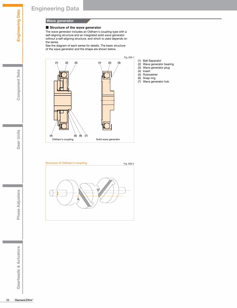
Engi
neer
ing
Dat
aC
ompo
nent
Set
sG
ear U
nits
Phas
e A
djus
ters
Gea
rhea
ds &
Act
uato
rs
Engi
neer
ing
Dat
aC
ompo
nent
Set
sG
ear U
nits
Phas
e A
djus
ters
Gea
rhea
ds &
Act
uato
rs
26
F F
H
φV'
8 11 14 17 20 25 32 40 45 50 58 65 80 90 100
3——
5——
638
8410
9513
11615
14615
141020
191020
191020
221325
241630
281635
281937
282240
8 11 14 17 20 25 32 40 45 50 58 65 80 90 100
105.7
146.7
177.2
207.6
2311.3
2811.3
3613.7
4215.9
4717.8
5219
6021.4
6723.5
7228.5
8431.3
9534.9
F=2×—×0.07×tan 32°TD
F=2×—×0.07×tan 30°TD
F=2×—×0.07×tan 20°TD
FDT
Nm
Nm
■ Structure of the wave generatorThe wave generator includes an Oldham's coupling type with a self-aligning structure and an integrated solid wave generator without a self-aligning structure, and which is used depends on the series.See the diagram of each series for details. The basic structure of the wave generator and the shape are shown below.
Fig. 026-1
(1) (2) (3) (1) (2) (3)
(4) (5) (6) (7)Oldham's coupling
(1) Ball Separator(2) Wave generator bearing(3) Wave generator plug(4) Insert(5) Rubwasher(6) Snap ring(7) Wave generator hub
Solid wave generator
Wave generator
Fig. 026-2Structure of Oldham's coupling
■ Maximum hole diameter of wave generator
The standard hole dimension of the wave generator is shown for each size. The dimension can be changed within a range up to the maximum hole dimension. We recommend the dimension of keyway based on JIS standard. It is necessary that the dimension of keyways should sustain the transmission torque.* Tapered holes are also available.
In cases where a larger hole is required, use the wave generator without the Oldham coupling. The maximum diameter of the hole should be considered to prevent deformation of the Wave Generator plug by load torque. The dimension is shown in the table below and includes the dimension of depth of keyway.(This is the value including the dimension of the depth of keyway.)
Fig. 027-1Hole diameter of the wave generator
Hole diameter of the wave generator hub with Oldham coupling
Size
Size
Standard dim. (H7)Minimum hole dim.Maximum hole dim.
Maximum hole diameter without Oldham CouplingTable 027-2
Table 027-1
Unit: mm
Unit: mm
Max. hole dia.φV'Min. plug thick.H-0.1
0
■ Axial Force of Wave Generator
(Note)Please contact us for further information on attaching the Wave Generator to the input (motor) shaft.
When the gear is used to accelerate a load, the deflection of the Flexspline leads to an axial force acting on the Wave Generator. This axial force, which acts in the direction of the closed end of the Flexspline, must be supported by the bearings of the input shaft (motor shaft). When the gear is used to decelerate a load, an axial force acts to push the Wave Generator out of the Flexspline cup. Maximum axial force of the Wave Generator can be calculated by the equation shown below. The axial force may vary depending on its operating condition. The value of axial force tends to be a larger number when using high torque, extreme low speed and constant operation. The force is calculated (approximately) by the equation. In all cases, the Wave Generator must be axially (in bothdirections), as well as torsionally, fixed to the input shaft.
Axial force direction of the wave generator Fig. 027-2
direction for Axial force in acceleration
direction for Axial force in deceleration
Formula 027-1Calculation example
Model name: CSF seriesSize: 32Reduction ratio: 50Output torque: 382 Nm (maximum allowable momentary torque)
F=2× ------------------------ ×0.07×tan 30°382
(32×0.00254)
F=380N
Formula for Axial Force Table 027-3
Reduction ratio Calculation formula
30
50
80 or more
Axial forceSize
Output torque
See Figure 027-2Table 027-4Symbols for Formula
Engineering Data

Engi
neer
ing
Dat
aC
ompo
nent
Set
sG
ear U
nits
Phas
e A
djus
ters
Gea
rhea
ds &
Act
uato
rs
Engi
neer
ing
Dat
aC
ompo
nent
Set
sG
ear U
nits
Phas
e A
djus
ters
Gea
rhea
ds &
Act
uato
rs
27
F F
H
φV'
8 11 14 17 20 25 32 40 45 50 58 65 80 90 100
3——
5——
638
84
10
95
13
116
15
146
15
141020
191020
191020
221325
241630
281635
281937
282240
8 11 14 17 20 25 32 40 45 50 58 65 80 90 100
105.7
146.7
177.2
207.6
2311.3
2811.3
3613.7
4215.9
4717.8
5219
6021.4
6723.5
7228.5
8431.3
9534.9
F=2×—×0.07×tan 32°TD
F=2×—×0.07×tan 30°TD
F=2×—×0.07×tan 20°TD
FDT
Nm
Nm
■ Structure of the wave generatorThe wave generator includes an Oldham's coupling type with a self-aligning structure and an integrated solid wave generator without a self-aligning structure, and which is used depends on the series.See the diagram of each series for details. The basic structure of the wave generator and the shape are shown below.
Fig. 026-1
(1) (2) (3) (1) (2) (3)
(4) (5) (6) (7)Oldham's coupling
(1) Ball Separator(2) Wave generator bearing(3) Wave generator plug(4) Insert(5) Rubwasher(6) Snap ring(7) Wave generator hub
Solid wave generator
Wave generator
Fig. 026-2Structure of Oldham's coupling
■ Maximum hole diameter of wave generator
The standard hole dimension of the wave generator is shown for each size. The dimension can be changed within a range up to the maximum hole dimension. We recommend the dimension of keyway based on JIS standard. It is necessary that the dimension of keyways should sustain the transmission torque.* Tapered holes are also available.
In cases where a larger hole is required, use the wave generator without the Oldham coupling. The maximum diameter of the hole should be considered to prevent deformation of the Wave Generator plug by load torque. The dimension is shown in the table below and includes the dimension of depth of keyway.(This is the value including the dimension of the depth of keyway.)
Fig. 027-1Hole diameter of the wave generator
Hole diameter of the wave generator hub with Oldham coupling
Size
Size
Standard dim. (H7)Minimum hole dim.Maximum hole dim.
Maximum hole diameter without Oldham CouplingTable 027-2
Table 027-1
Unit: mm
Unit: mm
Max. hole dia.φV'Min. plug thick.H-0.1
0
■ Axial Force of Wave Generator
(Note)Please contact us for further information on attaching the Wave Generator to the input (motor) shaft.
When the gear is used to accelerate a load, the deflection of the Flexspline leads to an axial force acting on the Wave Generator. This axial force, which acts in the direction of the closed end of the Flexspline, must be supported by the bearings of the input shaft (motor shaft). When the gear is used to decelerate a load, an axial force acts to push the Wave Generator out of the Flexspline cup. Maximum axial force of the Wave Generator can be calculated by the equation shown below. The axial force may vary depending on its operating condition. The value of axial force tends to be a larger number when using high torque, extreme low speed and constant operation. The force is calculated (approximately) by the equation. In all cases, the Wave Generator must be axially (in bothdirections), as well as torsionally, fixed to the input shaft.
Axial force direction of the wave generator Fig. 027-2
direction for Axial force in acceleration
direction for Axial force in deceleration
Formula 027-1Calculation example
Model name: CSF seriesSize: 32Reduction ratio: 50Output torque: 382 Nm (maximum allowable momentary torque)
F=2× ------------------------ ×0.07×tan 30°382
(32×0.00254)
F=380N
Formula for Axial Force Table 027-3
Reduction ratio Calculation formula
30
50
80 or more
Axial forceSize
Output torque
See Figure 027-2Table 027-4Symbols for Formula
Engineering Data
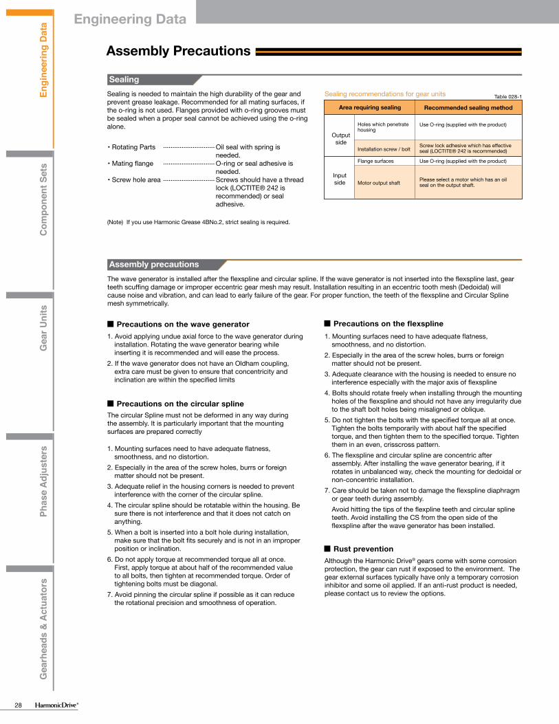
Engi
neer
ing
Dat
aC
ompo
nent
Set
sG
ear U
nits
Phas
e A
djus
ters
Gea
rhea
ds &
Act
uato
rs
Engi
neer
ing
Dat
aC
ompo
nent
Set
sG
ear U
nits
Phas
e A
djus
ters
Gea
rhea
ds &
Act
uato
rs
28
+
−
Assembly Precautions
Sealing
• Rotating Parts Oil seal with spring is needed.
• Mating flange O-ring or seal adhesive is needed.
• Screw hole area Screws should have a thread lock (LOCTITE® 242 is recommended) or seal adhesive.
(Note) If you use Harmonic Grease 4BNo.2, strict sealing is required.
The wave generator is installed after the flexspline and circular spline. If the wave generator is not inserted into the flexspline last, gear teeth scuffing damage or improper eccentric gear mesh may result. Installation resulting in an eccentric tooth mesh (Dedoidal) will cause noise and vibration, and can lead to early failure of the gear. For proper function, the teeth of the flexspline and Circular Spline mesh symmetrically.
■ Precautions on the wave generator1. Avoid applying undue axial force to the wave generator during
installation. Rotating the wave generator bearing while inserting it is recommended and will ease the process.
2. If the wave generator does not have an Oldham coupling, extra care must be given to ensure that concentricity and inclination are within the specified limits
■ Precautions on the circular spline
1. Mounting surfaces need to have adequate flatness, smoothness, and no distortion.
2. Especially in the area of the screw holes, burrs or foreign matter should not be present.
3. Adequate relief in the housing corners is needed to prevent interference with the corner of the circular spline.
4. The circular spline should be rotatable within the housing. Be sure there is not interference and that it does not catch on anything.
5. When a bolt is inserted into a bolt hole during installation, make sure that the bolt fits securely and is not in an improper position or inclination.
6. Do not apply torque at recommended torque all at once. First, apply torque at about half of the recommended value to all bolts, then tighten at recommended torque. Order of tightening bolts must be diagonal.
7. Avoid pinning the circular spline if possible as it can reduce the rotational precision and smoothness of operation.
■ Precautions on the flexspline1. Mounting surfaces need to have adequate flatness,
smoothness, and no distortion.2. Especially in the area of the screw holes, burrs or foreign
matter should not be present.3. Adequate clearance with the housing is needed to ensure no
interference especially with the major axis of flexspline 4. Bolts should rotate freely when installing through the mounting
holes of the flexspline and should not have any irregularity due to the shaft bolt holes being misaligned or oblique.
5. Do not tighten the bolts with the specified torque all at once. Tighten the bolts temporarily with about half the specified torque, and then tighten them to the specified torque. Tighten them in an even, crisscross pattern.
6. The flexspline and circular spline are concentric after assembly. After installing the wave generator bearing, if it rotates in unbalanced way, check the mounting for dedoidal or non-concentric installation.
7. Care should be taken not to damage the flexspline diaphragm or gear teeth during assembly.
Avoid hitting the tips of the flexpline teeth and circular spline teeth. Avoid installing the CS from the open side of the flexspline after the wave generator has been installed.
■ Rust preventionAlthough the Harmonic Drive® gears come with some corrosion protection, the gear can rust if exposed to the environment. The gear external surfaces typically have only a temporary corrosion inhibitor and some oil applied. If an anti-rust product is needed, please contact us to review the options.
Sealing recommendations for gear units Table 028-1
Area requiring sealing Recommended sealing method
Holes which penetrate housing
Use O-ring (supplied with the product)
Use O-ring (supplied with the product)
Installation screw / bolt
Flange surfaces
Please select a motor which has an oil seal on the output shaft.Motor output shaft
Screw lock adhesive which has effective seal (LOCTITE® 242 is recommended)
Output side
Input side
Assembly precautions
"Dedoidal" stateIt is normal for the flexspline to engage with the circular spline symmetrically as shown in Figure 029-1. However, if the ratcheting phenomenon, which is described on Page 013, is caused or if the three parts are forcibly inserted and assembled, engagement of the teeth may be out of alignment as shown in Figure 029-2. This is called "dedoidal". Note: Early failure of the gear will occur.
■ How to check "dedoidal"
Fig. 029-1Normal engagement status
By performing the following methods, check whether the gear engagement is "dedoidal".
(1) Judging by the irregular torque generated when the wave generator turns1) Slowly turn the input shaft with your hand in a no-load
condition. If you can turn it with average force, it is normal. If it turns irregularly, it may be "dedoidal".
2) Turn the wave generator in a no-load condition if it is attached to a motor. If the average current value of the motor is about 2 to 3 times the normal value, it may be "dedoidal".
(2) Judging by measuring vibration on the body of the flexspline
The scale deflection of the dial gauge draws a sine wave as shown by the solid line in Graph 029-3 when it is normally assembled. When "dedoidal" occurs, the gauge draws a deflected wave shown by the dotted line as the flexspline is out of alignment.
Fig. 029-2"Dedoidal" status
Dedoidal
Defl
ectio
n of
the
dial
gau
ge
180o rotation
360o rotation
Normal
Rotational angle of the wave generatorRotational angle of the wave generator
Fig. 029-4
Graph 029-3Deflection of the dial gauge
Measuring the deflection on the body of the flexspline
Rotational angle of the wave generator
Dial gauge
The circular Spline must not be deformed in any way during the assembly. It is particularly important that the mounting surfaces are prepared correctly
Sealing is needed to maintain the high durability of the gear and prevent grease leakage. Recommended for all mating surfaces, if the o-ring is not used. Flanges provided with o-ring grooves must be sealed when a proper seal cannot be achieved using the o-ring alone.
Engineering Data

Engi
neer
ing
Dat
aC
ompo
nent
Set
sG
ear U
nits
Phas
e A
djus
ters
Gea
rhea
ds &
Act
uato
rs
Engi
neer
ing
Dat
aC
ompo
nent
Set
sG
ear U
nits
Phas
e A
djus
ters
Gea
rhea
ds &
Act
uato
rs
29
+
−
Assembly Precautions
Sealing
• Rotating Parts Oil seal with spring is needed.
• Mating flange O-ring or seal adhesive is needed.
• Screw hole area Screws should have a thread lock (LOCTITE® 242 is recommended) or seal adhesive.
(Note) If you use Harmonic Grease 4BNo.2, strict sealing is required.
The wave generator is installed after the flexspline and circular spline. If the wave generator is not inserted into the flexspline last, gear teeth scuffing damage or improper eccentric gear mesh may result. Installation resulting in an eccentric tooth mesh (Dedoidal) will cause noise and vibration, and can lead to early failure of the gear. For proper function, the teeth of the flexspline and Circular Spline mesh symmetrically.
■ Precautions on the wave generator1. Avoid applying undue axial force to the wave generator during
installation. Rotating the wave generator bearing while inserting it is recommended and will ease the process.
2. If the wave generator does not have an Oldham coupling, extra care must be given to ensure that concentricity and inclination are within the specified limits
■ Precautions on the circular spline
1. Mounting surfaces need to have adequate flatness, smoothness, and no distortion.
2. Especially in the area of the screw holes, burrs or foreign matter should not be present.
3. Adequate relief in the housing corners is needed to prevent interference with the corner of the circular spline.
4. The circular spline should be rotatable within the housing. Be sure there is not interference and that it does not catch on anything.
5. When a bolt is inserted into a bolt hole during installation, make sure that the bolt fits securely and is not in an improper position or inclination.
6. Do not apply torque at recommended torque all at once. First, apply torque at about half of the recommended value to all bolts, then tighten at recommended torque. Order of tightening bolts must be diagonal.
7. Avoid pinning the circular spline if possible as it can reduce the rotational precision and smoothness of operation.
■ Precautions on the flexspline1. Mounting surfaces need to have adequate flatness,
smoothness, and no distortion.2. Especially in the area of the screw holes, burrs or foreign
matter should not be present.3. Adequate clearance with the housing is needed to ensure no
interference especially with the major axis of flexspline 4. Bolts should rotate freely when installing through the mounting
holes of the flexspline and should not have any irregularity due to the shaft bolt holes being misaligned or oblique.
5. Do not tighten the bolts with the specified torque all at once. Tighten the bolts temporarily with about half the specified torque, and then tighten them to the specified torque. Tighten them in an even, crisscross pattern.
6. The flexspline and circular spline are concentric after assembly. After installing the wave generator bearing, if it rotates in unbalanced way, check the mounting for dedoidal or non-concentric installation.
7. Care should be taken not to damage the flexspline diaphragm or gear teeth during assembly.
Avoid hitting the tips of the flexpline teeth and circular spline teeth. Avoid installing the CS from the open side of the flexspline after the wave generator has been installed.
■ Rust preventionAlthough the Harmonic Drive® gears come with some corrosion protection, the gear can rust if exposed to the environment. The gear external surfaces typically have only a temporary corrosion inhibitor and some oil applied. If an anti-rust product is needed, please contact us to review the options.
Sealing recommendations for gear units Table 028-1
Area requiring sealing Recommended sealing method
Holes which penetrate housing
Use O-ring (supplied with the product)
Use O-ring (supplied with the product)
Installation screw / bolt
Flange surfaces
Please select a motor which has an oil seal on the output shaft.Motor output shaft
Screw lock adhesive which has effective seal (LOCTITE® 242 is recommended)
Output side
Input side
Assembly precautions
"Dedoidal" stateIt is normal for the flexspline to engage with the circular spline symmetrically as shown in Figure 029-1. However, if the ratcheting phenomenon, which is described on Page 013, is caused or if the three parts are forcibly inserted and assembled, engagement of the teeth may be out of alignment as shown in Figure 029-2. This is called "dedoidal". Note: Early failure of the gear will occur.
■ How to check "dedoidal"
Fig. 029-1Normal engagement status
By performing the following methods, check whether the gear engagement is "dedoidal".
(1) Judging by the irregular torque generated when the wave generator turns1) Slowly turn the input shaft with your hand in a no-load
condition. If you can turn it with average force, it is normal. If it turns irregularly, it may be "dedoidal".
2) Turn the wave generator in a no-load condition if it is attached to a motor. If the average current value of the motor is about 2 to 3 times the normal value, it may be "dedoidal".
(2) Judging by measuring vibration on the body of the flexspline
The scale deflection of the dial gauge draws a sine wave as shown by the solid line in Graph 029-3 when it is normally assembled. When "dedoidal" occurs, the gauge draws a deflected wave shown by the dotted line as the flexspline is out of alignment.
Fig. 029-2"Dedoidal" status
Dedoidal
Defl
ectio
n of
the
dial
gau
ge
180o rotation
360o rotation
Normal
Rotational angle of the wave generatorRotational angle of the wave generator
Fig. 029-4
Graph 029-3Deflection of the dial gauge
Measuring the deflection on the body of the flexspline
Rotational angle of the wave generator
Dial gauge
The circular Spline must not be deformed in any way during the assembly. It is particularly important that the mounting surfaces are prepared correctly
Sealing is needed to maintain the high durability of the gear and prevent grease leakage. Recommended for all mating surfaces, if the o-ring is not used. Flanges provided with o-ring grooves must be sealed when a proper seal cannot be achieved using the o-ring alone.
Engineering Data

Engi
neer
ing
Dat
aC
ompo
nent
Set
sG
ear U
nits
Phas
e A
djus
ters
Gea
rhea
ds &
Act
uato
rs
Engi
neer
ing
Dat
aC
ompo
nent
Set
sG
ear U
nits
Phas
e A
djus
ters
Gea
rhea
ds &
Act
uato
rs
30
Frmax
Famax
Lr, La
R
N(kgf)
N(kgf)
m
m
Frav
Faav
Lr, La
R
dp
dp
La
Lr RFa
Fr
Nav = –––––––––––––––––––n1t1 + n2t2 …+ nntn
t1 + t2 …+ tn
n 1 n 3
t 1 t 2 t 3
n 2
Fa 1
Fa 2
Fa 3
Fr 1
Fr 2
Fr 3
1
0.67
<=1.5
>1.5
0.45
0.67
FaavFrav+2 (Frav (Lr+R) + Frav • La) /dp
X Y
M = Fr (Lr+R) +Fa ・Lamax max max
av
av
av
av
m
m
m
N(kgf)
N(kgf)
FaavFrav+2 (Frav (Lr+R) + Frav • La) /dp
A precision cross roller bearing is built in the unit type and the gear head type to directly support the external load (output flange) (precision 4-point contact ball bearing for the CSF-mini series).Please calculate maximum moment load, life of cross roller bearing, and static safety factor to fully maximize the performance of a housed unit (gearhead).
■ See the corresponding pages on each series for cross roller bearing specifications.
Checking Output Bearing
Checking procedure
(1) Checking the maximum moment load (Mmax)
(3) Checking the static safety coefficient
Calculate maximum moment load (Mmax).
Calculate the radial load (Frav) and the average axial load (Faav).
Calculate the static equivalent radial load coefficient (Po).
Check the static safety coefficient. (fs)
Calculate lifetime
Calculate the radial load coefficient (x) and the axial load coefficient (y).
Maximum moment load (Mmax) ≦ allowable moment (Mc)
(2) Checking the life
How to calculate the maximum moment loadMaximum moment load (Mmax) is obtained as follows.Make sure that Mmax ≦ Mc.
Formula 030-1
Table 030-1Symbols for Formula 030-1
Max. radial load See Fig. 030-1.
See Fig. 030-1.
See Fig. 030-1.
See Fig. 030-1 and "Specification of the output bearing" of each series.
Max. axial load
—
Offset amount
Fig. 030-1External load influence diagram
Load
Radial load
Axial load
Fixed
How to calculate the average load
(Average radial load, average axial load, average output speed)When the radial load and axial load vary, the life of cross roller bearing can be determined by converting to an average load.
How to calculate the average radial load (Frav) Formula 031-1
Note that the maximum radial load in t1 is Fr1 and the maximum radial load in t3 is Fr3.
How to calculate the average axial load (Faav)
How to calculate the average output speed (Nav)
Formula 031-2
Formula 031-3
Note that the maximum axial load in t1 is Fa1 and the maximum axial load in t3 is Fa3.
+
−
+
−
+
−
Graph 031-1
Time
Time
Time
Axia
l loa
dOu
tput
spe
edRa
dial
load
How to calculate the radial load coefficient (X) and axial load coefficient (Y)
Formula 031-4
Table 031-1
How to calculate the load coefficient
Symbols for Formula 031-4
Average radial load
Average axial load
Pitch circle diameter of a roller
See "How to calculate the average load." See Formula 031-1.
See "How to calculate the average load." See Formula 031-2.
See Fig. 030-1 and "Specification of the output bearing" of each series.
See fig. 030-1
See Fig. 030-1 and "Main roller bearing specifications" of each series
Offset amount
__________
(Cross roller bearing)
(4-point contact ball bearing)
(Cross roller bearing)
(4-point contact ball bearing)
Engineering Data

Engi
neer
ing
Dat
aC
ompo
nent
Set
sG
ear U
nits
Phas
e A
djus
ters
Gea
rhea
ds &
Act
uato
rs
Engi
neer
ing
Dat
aC
ompo
nent
Set
sG
ear U
nits
Phas
e A
djus
ters
Gea
rhea
ds &
Act
uato
rs
31
Frmax
Famax
Lr, La
R
N(kgf)
N(kgf)
m
m
Frav
Faav
Lr, La
R
dp
dp
La
Lr RFa
Fr
Nav = –––––––––––––––––––n1t1 + n2t2 …+ nntn
t1 + t2 …+ tn
n 1 n 3
t 1 t 2 t 3
n 2
Fa 1
Fa 2
Fa 3
Fr 1
Fr 2
Fr 3
1
0.67
<=1.5
>1.5
0.45
0.67
FaavFrav+2 (Frav (Lr+R) + Frav • La) /dp
X Y
M = Fr (Lr+R) +Fa ・Lamax max max
av
av
av
av
m
m
m
N(kgf)
N(kgf)
FaavFrav+2 (Frav (Lr+R) + Frav • La) /dp
A precision cross roller bearing is built in the unit type and the gear head type to directly support the external load (output flange) (precision 4-point contact ball bearing for the CSF-mini series).Please calculate maximum moment load, life of cross roller bearing, and static safety factor to fully maximize the performance of a housed unit (gearhead).
■ See the corresponding pages on each series for cross roller bearing specifications.
Checking Output Bearing
Checking procedure
(1) Checking the maximum moment load (Mmax)
(3) Checking the static safety coefficient
Calculate maximum moment load (Mmax).
Calculate the radial load (Frav) and the average axial load (Faav).
Calculate the static equivalent radial load coefficient (Po).
Check the static safety coefficient. (fs)
Calculate lifetime
Calculate the radial load coefficient (x) and the axial load coefficient (y).
Maximum moment load (Mmax) ≦ allowable moment (Mc)
(2) Checking the life
How to calculate the maximum moment loadMaximum moment load (Mmax) is obtained as follows.Make sure that Mmax ≦ Mc.
Formula 030-1
Table 030-1Symbols for Formula 030-1
Max. radial load See Fig. 030-1.
See Fig. 030-1.
See Fig. 030-1.
See Fig. 030-1 and "Specification of the output bearing" of each series.
Max. axial load
—
Offset amount
Fig. 030-1External load influence diagram
Load
Radial load
Axial load
Fixed
How to calculate the average load
(Average radial load, average axial load, average output speed)When the radial load and axial load vary, the life of cross roller bearing can be determined by converting to an average load.
How to calculate the average radial load (Frav) Formula 031-1
Note that the maximum radial load in t1 is Fr1 and the maximum radial load in t3 is Fr3.
How to calculate the average axial load (Faav)
How to calculate the average output speed (Nav)
Formula 031-2
Formula 031-3
Note that the maximum axial load in t1 is Fa1 and the maximum axial load in t3 is Fa3.
+
−
+ −
+
−
Graph 031-1
Time
Time
Time
Axia
l loa
dOu
tput
spe
edRa
dial
load
How to calculate the radial load coefficient (X) and axial load coefficient (Y)
Formula 031-4
Table 031-1
How to calculate the load coefficient
Symbols for Formula 031-4
Average radial load
Average axial load
Pitch circle diameter of a roller
See "How to calculate the average load." See Formula 031-1.
See "How to calculate the average load." See Formula 031-2.
See Fig. 030-1 and "Specification of the output bearing" of each series.
See fig. 030-1
See Fig. 030-1 and "Main roller bearing specifications" of each series
Offset amount
__________
(Cross roller bearing)
(4-point contact ball bearing)
(Cross roller bearing)
(4-point contact ball bearing)
Engineering Data

Engi
neer
ing
Dat
aC
ompo
nent
Set
sG
ear U
nits
Phas
e A
djus
ters
Gea
rhea
ds &
Act
uato
rs
Engi
neer
ing
Dat
aC
ompo
nent
Set
sG
ear U
nits
Phas
e A
djus
ters
Gea
rhea
ds &
Act
uato
rs
32
L10
Nav
C
Pc
fw
hour
rpm
N(kgf)
N(kgf)
——
Frav
Faav
dp
X
Y
Lr, La
R
M ave
N(kgf)
N(kgf)
m
——
——
m
m
Nm
Loc
n1
C
Pc
fw
θ
hour
cpm
N(kgf)
N(kgf)
——
Degree
fw
Pc = X • Frav + ––––––––––––––––––––– +Y・Faav2(Frav (Lr+R) + Frav • La)
dp
θ
L10 = –––––––––––– × ––––––––106
60 × NC
fw•Pc10/3
Loc = –––––––––––– × –––––––– × ––––––––
Loc = –––––––––––– × –––––––– × ––––––––
106
106
60 × n1
60 × n1
90
90
θ
θ
C
C
fw・Pc
fw・Pc
10/3
3
av
L10 = –––––––––––– × ––––––––106
60 × NC
fw•Pc3
av
Calculate life of the output bearing by Formula 032-1.You can calculate the dynamic equivalent radial load (Pc) by Formula 032-2.
Life of the output bearing
Formula 032-1 Formula 032-2
Table 032-1
Table 032-2
Symbols for Formula 032-1
Symbols for Formula 032-2
See "How to calculate the average load."
See Formula 032-2.
See Table 032-3.
See "Specification of the output bearing" of each series.
Average output rated load speed
Basic dynamic rated load
Dynamic equivalent
Load coefficient
Life ———
(Cross roller bearing)
(4-point contact ball bearing)
Load coefficient Table 032-3
Load status
Steady operation without impact and vibration
Operation with impact and vibrationNormal operation
Average radial load
Radial load coefficient
See "How to calculate the average load." See Formula 031-1.
See Formula 031-4.
Axial load coefficient See Formula 031-4.
——— See Figure 030-1.
Average axial load See "How to calculate the average load." See Formula 031-2.
Offset
Average moment load
See Fig. 030-1 and "Specification of the output bearing" of each series.
Pitch circle diameter
See Fig. 030-1 and "Specification of the output bearing" of each series.
Rated life for oscillating motion
Round trip oscillation each minute
Dynamic equivalent radial load
Load coefficient
Oscillating angle /2
Basic dynamic rated load
———
———
See Formula 032-2.
See Table 032-3.
See Fig. 033-1.
———
How to calculate life during oscillating motion
Calculate the life of the cross roller bearing during oscillating motion by Formula 033-1.
Formula 033-1
Table 033-1Symbols for Formula 033-1Oscillating angle
(Note) A small angle of oscillation (less than 5 degrees) may cause fretting corrosion to occur since lubrication may not circulate properly. Contact us if this happens.
Fig. 033-1
(Cross roller bearing)
(4-point contact ball bearing)
1 to 1.21.2 to 1.51.5 to 3
Engineering Data

Engi
neer
ing
Dat
aC
ompo
nent
Set
sG
ear U
nits
Phas
e A
djus
ters
Gea
rhea
ds &
Act
uato
rs
Engi
neer
ing
Dat
aC
ompo
nent
Set
sG
ear U
nits
Phas
e A
djus
ters
Gea
rhea
ds &
Act
uato
rs
33
L10
Nav
C
Pc
fw
hour
rpm
N(kgf)
N(kgf)
——
Frav
Faav
dp
X
Y
Lr, La
R
M ave
N(kgf)
N(kgf)
m
——
——
m
m
Nm
Loc
n1
C
Pc
fw
θ
hour
cpm
N(kgf)
N(kgf)
——
Degree
fw
Pc = X • Frav + ––––––––––––––––––––– +Y・Faav2(Frav (Lr+R) + Frav • La)
dp
θ
L10 = –––––––––––– × ––––––––106
60 × NC
fw•Pc10/3
Loc = –––––––––––– × –––––––– × ––––––––
Loc = –––––––––––– × –––––––– × ––––––––
106
106
60 × n1
60 × n1
90
90
θ
θ
C
C
fw・Pc
fw・Pc
10/3
3
av
L10 = –––––––––––– × ––––––––106
60 × NC
fw•Pc3
av
Calculate life of the output bearing by Formula 032-1.You can calculate the dynamic equivalent radial load (Pc) by Formula 032-2.
Life of the output bearing
Formula 032-1 Formula 032-2
Table 032-1
Table 032-2
Symbols for Formula 032-1
Symbols for Formula 032-2
See "How to calculate the average load."
See Formula 032-2.
See Table 032-3.
See "Specification of the output bearing" of each series.
Average output rated load speed
Basic dynamic rated load
Dynamic equivalent
Load coefficient
Life ———
(Cross roller bearing)
(4-point contact ball bearing)
Load coefficient Table 032-3
Load status
Steady operation without impact and vibration
Operation with impact and vibrationNormal operation
Average radial load
Radial load coefficient
See "How to calculate the average load." See Formula 031-1.
See Formula 031-4.
Axial load coefficient See Formula 031-4.
——— See Figure 030-1.
Average axial load See "How to calculate the average load." See Formula 031-2.
Offset
Average moment load
See Fig. 030-1 and "Specification of the output bearing" of each series.
Pitch circle diameter
See Fig. 030-1 and "Specification of the output bearing" of each series.
Rated life for oscillating motion
Round trip oscillation each minute
Dynamic equivalent radial load
Load coefficient
Oscillating angle /2
Basic dynamic rated load
———
———
See Formula 032-2.
See Table 032-3.
See Fig. 033-1.
———
How to calculate life during oscillating motion
Calculate the life of the cross roller bearing during oscillating motion by Formula 033-1.
Formula 033-1
Table 033-1Symbols for Formula 033-1Oscillating angle
(Note) A small angle of oscillation (less than 5 degrees) may cause fretting corrosion to occur since lubrication may not circulate properly. Contact us if this happens.
Fig. 033-1
(Cross roller bearing)
(4-point contact ball bearing)
1 to 1.21.2 to 1.51.5 to 3
Engineering Data

Engi
neer
ing
Dat
aC
ompo
nent
Set
sG
ear U
nits
Phas
e A
djus
ters
Gea
rhea
ds &
Act
uato
rs
Engi
neer
ing
Dat
aC
ompo
nent
Set
sG
ear U
nits
Phas
e A
djus
ters
Gea
rhea
ds &
Act
uato
rs
34
Engineering Data
Co
Po
N(kgf)
N(kgf)
Frmax
Famax
Mmax
dp
N(kgf)
N(kgf)
Nm(kgfm)
m≧3≧2≧1.5
fs
Po = Fr + ——————–––––– +0.44Fa2M
dpmax
maxmax
036037038040042042042042043043044044044046048051051052
059
fs= ——————CoPo
CSG
CSF
CSD
SHG
SHF
FB
FR
035035061079079103105
Component Set CSG/CSF
How to calculate the static safety coefficientBasic static rated load is an allowable limit for static load, but its limit is determined by usage. In this case, static safety coefficient of the cross roller bearing can be calculated by Formula 034-2.
Formula 034-1 Formula 034-2
Table 034-2Symbols for Formula 034-2
Max. radial load
Max. axial loadSee "How to calculate the maximum moment load" on Page 030.
Max. moment load
Pitch circle diameter of a roller
See Fig. 030-1 and "Specification of the output bearing" of each series.
Table 034-1
Table 034-3
Symbols for Formula 034-1
Static Safety Coefficient
Basic static rated load
Static equivalent radial load
When high rotation precision is requiredWhen shock and vibration are expected
Under normal operating condition
Operating condition of the roller bearing
See "Specification of the output bearing" of each series.
See Formula 034-2.
Features
Technical data
Ordering code
Design guide
CSG/CSF Series
Rating table
Outline drawing and dimensions
Positional accuracy
Hysteresis loss
Backlash
Torsional stiffness
Starting torque
Backdriving torque
Ratcheting torque
Buckling torque
No-load running torque
Efficiency
Lubrication
Assembly tolerances
Sealing
Installation of the three basic elements
Application

328Rev 20180416
Group Companies Harmonic Drive Systems, Inc. 6-25-3 Minami-Ohi, Shinagawa-ku Tokyo 141-0013, Japan
Harmonic Drive AG Hoenbergstrasse, 14, D-6555 Limburg/Lahn Germany
Harmonic Drive®, Harmonic Gearhead®, Harmonic Planetary® and Quick Connect® are registered trade-marks of Harmonic Drive LLC. All other trademarks are property of their respective owners.
Harmonic Drive LLCBoston US Headquarters247 Lynnfield Street Peabody, MA 01960
New York Sales Office100 Motor ParkwaySuite 116Hauppauge, NY 11788
California Sales Office333 W. San Carlos Street Suite 1070San Jose, CA 95110
Chicago Sales Office137 N. Oak Park Ave., Suite 410Oak Park, IL 60301
T: 800.921.3332 T: 978.532.1800 F: 978.532.9406
www.HarmonicDrive.net