Motors | Energy | Automation | Coatings
Rack 2 / Rack 3
CFW-11M / RMW11
Installation GuideGuía de InstalaciónGuia de Instalação
English / Español / Português

Summary
1. General Information ........................................................................................................52. Mechanical Dimensions ...................................................................................................53. Bill of Materials ...............................................................................................................64. Installation ......................................................................................................................7
Índice
1. Informaciones Generales ................................................................................................122. Dimensiones Mecánicas .................................................................................................123. Listado de Piezas ............................................................................................................134. Instalación .....................................................................................................................14
Índice
1. Informações Gerais ........................................................................................................192. Dimensões Mecânicas ....................................................................................................193. Lista de Peças ................................................................................................................204. Instalação .....................................................................................................................21

5
EN
GLI
SH
Installation Guide Rack 2 / Rack 3 – CFW-11M and RMW11 Rack
1. GENERAL INFORMATION
This guide orients the installation of the Rack 2 and Rack 3 mechanical accessories, used to facilitate the installation of the modular rectifiers and inverters (book format) RMW11 and CFW-11M in cabinets.
The Rack 2 accessory allows the installation of 1 or 2 modules side by side in 600 mm (23.6 in) wide cabinets.
The Rack 3 accessory allows the installation of 1, 2 or 3 modules side by side in 1000 mm (39.4 in) wide cabinets.
2. MECHANICAL DIMENSIONS
[20.4]517
[23.
7]60
3[1
9.0]
483
[14.
3]36
3[9
.6]
243
[4.8
]12
3
[0.3]7.5
[26.50]673
[1.2]30
[19.8]502 [0.4]
ø9.2(5x)
[0.4]ø9.2(5x)
[0.4]ø9.2(60x)
[0.4]ø9.2(60x)
[0.4]ø9.2
[0.4]ø9.2
[19.8]502
[1.0
]25
[61.
0]15
48.5
[1.3
]32
.6
[29.
5]74
8.5
1548
.50
[61]
36
[1.4
]
673
[26.5]
[57.
0]14
48.5
517 [20.3]
[59.
5]15
11
Figure 1 - Rack 2 Dimensions in mm [in]
6
EN
GLI
SH
[29.61]752
[23.
74]
603
[19.
01]
483
[14.
29]
363 [9
.6]
243
[4.8
]12
3
[0.30]7.50
[26.50]673
[1.18]30
[29.02]737
[0.36]
ø9.20
[0.3
6]ø9.
2
[0.36
]
ø9.2
[0.36
]
ø9.2
[0.36]
ø9.2
[0.36]
ø9.2
[29.02]737
[19.13]486
[9.88]251
[9.25]235
[10.18]258.50
[0.9
8]25
[60.
96]
1548
.50
[1.2
8]33
[29.
47]
748.
50
1548
.50
[61]
36
[1.4
]
673
[26.5]
[57.
03]
1448
.50
752[29.6]
[59.
49]
1511
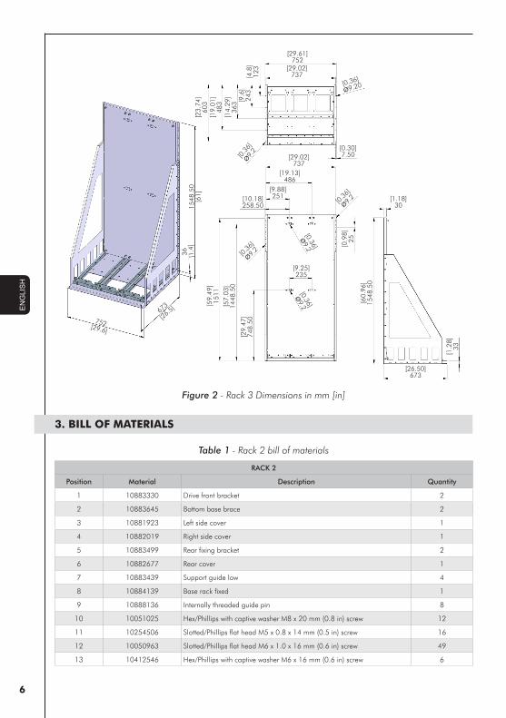
Figure 2 - Rack 3 Dimensions in mm [in]
3. BILL OF MATERIALS
Table 1 - Rack 2 bill of materials
RACK 2
Position Material Description Quantity
1 10883330 Drive front bracket 2
2 10883645 Bottom base brace 2
3 10881923 Left side cover 1
4 10882019 Right side cover 1
5 10883499 Rear fixing bracket 2
6 10882677 Rear cover 1
7 10883439 Support guide low 4
8 10884139 Base rack fixed 1
9 10888136 Internally threaded guide pin 8
10 10051025 Hex/Phillips with captive washer M8 x 20 mm (0.8 in) screw 12
11 10254506 Slotted/Phillips flat head M5 x 0.8 x 14 mm (0.5 in) screw 16
12 10050963 Slotted/Phillips flat head M6 x 1.0 x 16 mm (0.6 in) screw 49
13 10412546 Hex/Phillips with captive washer M6 x 16 mm (0.6 in) screw 6

7
EN
GLI
SH
Table 2 - Rack 3 bill of materials
RACK 3
Position Material Description Quantity
1 10883330 Drive front bracket 3
2 10884898 Bottom base brace 2
3 10881923 Left side cover 1
4 10882019 Right side cover 1
5 10883499 Rear fixing bracket 4
6 10884510 Rear cover 1
7 10883439 Support guide low 6
8 10884757 Base rack fixed 1
9 10888136 Internally threaded guide pin 12
10 10051025 Hex/Phillips with captive washer M8 x 20 mm (0.8 in) screw 18
11 10254506 Slotted/Phillips flat head M5 x 0.8 x 14 mm (0.5 in) screw 24
12 10050963 Slotted/Phillips flat head M6 x 1.0 x 16 mm (0.6 in) screw 53
13 10412546 Hex/Phillips with captive washer M6 x 16 mm (0.6 in) screw 9
NOTES! - M5 screws recommended tightening torque: 5.0 Nm ± 15 %.- M6 screws recommended tightening torque: 8.5 Nm ± 15 %.- M8 screws recommended tightening torque: 19.0 Nm ± 15 %.
4. INSTALLATION
- Rack assembling according to figures 3 and 4.- Installation of the rack inside the cabinet according to figures 7 and 8.
Figure 3 - Assembling of the rack for 2 power modules
8
EN
GLI
SH
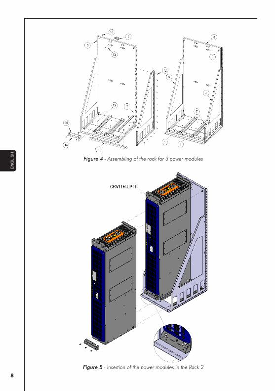
Figure 4 - Assembling of the rack for 3 power modules
Figure 5 - Insertion of the power modules in the Rack 2

9
EN
GLI
SH
Figure 6 - Insertion of the power modules in the Rack 3

10
EN
GLI
SH
Figure 7 - Details for mounting the Rack 2 in a 600 mm (23.6 in) wide cabinet
11
EN
GLI
SH
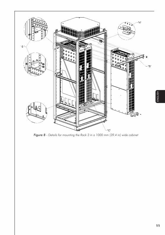
Figure 8 - Details for mounting the Rack 3 in a 1000 mm (39.4 in) wide cabinet
12
ES
PAÑ
OL
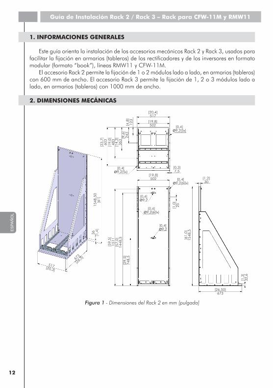
1. INFORMACIONES GENERALES
Este guía orienta la instalación de los accesorios mecánicos Rack 2 y Rack 3, usados para facilitar la fijación en armarios (tableros) de los rectificadores y de los inversores en formato modular (formato “book”), líneas RMW11 y CFW-11M.
El accesorio Rack 2 permite la fijación de 1 o 2 módulos lado a lado, en armarios (tableros) con 600 mm de ancho. El accesorio Rack 3 permite la fijación de 1, 2 o 3 módulos lado a lado, en armarios (tableros) con 1000 mm de ancho.
2. DIMENSIONES MECÁNICAS
[20,4]517
[23,
7]60
3[1
9,0]
483
[14,
3]36
3[9
,6]
243
[4,8
]12
3
[0,3]7,5
[26,50]673
[1,2]30
[19,8]502 [0,4]
ø9,2(5x)
[0,4]ø9,2(5x)
[0,4]ø9,2(60x)
[0,4]ø9,2(60x)
[0,4]ø9,2
[0,4]ø9,2
[19,8]502
[1,0
]25
[61,
0]15
48,5
[1,3
]32
,6
[29,
5]74
8,5
1548
,50
[61]
36
[1,4
]
673
[26,5]
[57,
0]14
48,5
517 [20,3]
[59,
5]15
11
Figura 1 - Dimensiones del Rack 2 en mm [pulgada]
Guía de Instalación Rack 2 / Rack 3 – Rack para CFW-11M y RMW11

13
ES
PAÑ
OL
[29,61]752
[23,
74]
603
[19,
01]
483
[14,
29]
363 [9
,6]
243
[4,8
]12
3
[0,30]7,50
[26,50]673
[1,18]30
[29,02]737
[0,36]
ø9,20
[0,3
6]ø9,
2
[0,36
]
ø9,2
[0,36
]
ø9,2
[0,36]
ø9,2
[0,36]
ø9,2
[29,02]737
[19,13]486
[9,88]251
[9,25]235
[10,18]258,50
[0,9
8]25
[60,
96]
1548
,50
[1,2
8]33
[29,
47]
748,
50
1548
,50
[61]
36
[1,4
]
673
[26,5]
[57,
03]
1448
,50
752[29,6]
[59,
49]
1511
Figura 2 - Dimensiones del Rack 3 en mm [pulgada]
3. LISTADO DE PIEZAS
Tabla 1 - Listado de piezas del Rack 2
RACK 2
Posición Material Descripción Cantidad
1 10883330 Soporte frontal drive 2
2 10883645 Refuerza base inferior 2
3 10881923 Tapa lateral izquierdo 1
4 10882019 Tapa lateral derecho 1
5 10883499 Soporte de fijación posterior 2
6 10882677 Tapa posterior 1
7 10883439 Soporte guía inferior 4
8 10884139 Base rack fijo 1
9 10888136 Pino guía rosca interna 8
10 10051025 Tornillo con arandela sextavado phillips M8 x 20 mm 12
11 10254506 Tornillo escariado tipo cruz M5 x 0,8 x 14 mm 16
12 10050963 Tornillo escariado tipo cruz M6 x 1,0 x 16 mm 49
13 10412546 Tornillo con arandela sextavado phillips M6 x 16 mm 6

14
ES
PAÑ
OL
Tabla 2 - Listado de piezas del Rack 3
RACK 3
Posición Material Denominación Cantidad
1 10883330 Soporte frontal drive 3
2 10884898 Refuerzo base inferior 2
3 10881923 Tapa lateral izquierdo 1
4 10882019 Tapa lateral derecho 1
5 10883499 Soporte de fijación posterior 4
6 10884510 Tapa posterior 1
7 10883439 Soporte guía inferior 6
8 10884757 Base rack fijo 1
9 10888136 Pino guía rosca interna 12
10 10051025 Tornillo con arandela sextavado phillips M8 x 20 mm 18
11 10254506 Tornillo escariado tipo cruz M5 x 0,8 x 14 mm 24
12 10050963 Tornillo escariado tipo cruz M6 x 1,0 x 16 mm 53
13 10412546 Tornillo con arandela sextavado phillips M6 x 16 mm 9
¡NOTAS! - Par (Torque) de aprieto recomendado para los tornillos M5: 5,0 N.m ± 15 %.- Par (Torque) de aprieto recomendado para los tornillos M6: 8,5 N.m ± 15 %.- Par (Torque) de aprieto recomendado para los tornillos M8: 19,0 N.m ± 15 %.
4. INSTALACIÓN
- El montaje del RACK conforme las figuras 3 y 4.- Instalación del RACK en el armario (tablero) conforme las figuras 7 y 8.
Figura 3 - Montaje del rack para 2 módulos de potencia
15
ES
PAÑ
OL
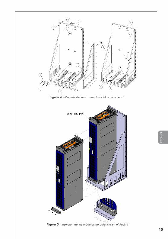
Figura 4 - Montaje del rack para 3 módulos de potencia
Figura 5 - Inserción de los módulos de potencia en el Rack 2

16
ES
PAÑ
OL
Figura 6 - Inserción de los módulos de potencia en el Rack 3

17
ES
PAÑ
OL
Figura 7 - Detalles de montaje del Rack 2 en armario (tablero) con 600 mm de ancho

18
ES
PAÑ
OL
Figura 8 - Detalles de montaje del Rack 3 en armario (tablero) con 1000 mm de ancho
19
PO
RTU
GU
ÊS
1. INFORMAÇÕES GERAIS
Este guia orienta a fixação dos acessórios mecânicos Rack 2 e Rack 3, usados para facilitar a fixação em painel dos retificadores e inversores em formato modular (formato “book”), linhas RMW11 e CFW-11M.
O acessório Rack 2 permite a fixação de 1 ou 2 módulos lado a lado, em painéis com 600 mm de largura.
O acessório Rack 3 permite a fixação de 1, 2 ou 3 módulos lado a lado, em painéis com 1000 mm de largura.
2. DIMENSÕES MECÂNICAS
[20,4]517
[23,
7]60
3[1
9,0]
483
[14,
3]36
3[9
,6]
243
[4,8
]12
3
[0,3]7,5
[26,50]673
[1,2]30
[19,8]502 [0,4]
ø9,2(5x)
[0,4]ø9,2(5x)
[0,4]ø9,2(60x)
[0,4]ø9,2(60x)
[0,4]ø9,2
[0,4]ø9,2
[19,8]502
[1,0
]25
[61,
0]15
48,5
[1,3
]32
,6
[29,
5]74
8,5
1548
,50
[61]
36
[1,4
]
673
[26,5]
[57,
0]14
48,5
517 [20,3]
[59,
5]15
11
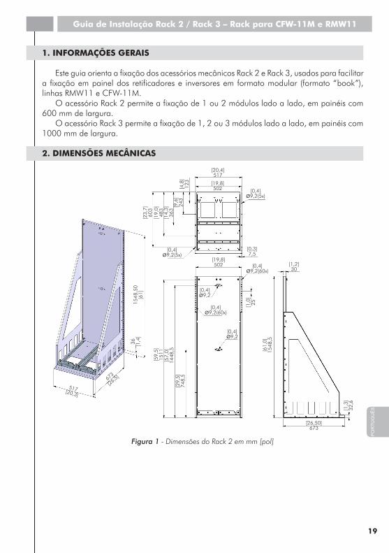
Figura 1 - Dimensões do Rack 2 em mm [pol]
Guia de Instalação Rack 2 / Rack 3 – Rack para CFW-11M e RMW11

20
PO
RTU
GU
ÊS
[29,61]752
[23,
74]
603
[19,
01]
483
[14,
29]
363 [9
,6]
243
[4,8
]12
3
[0,30]7,50
[26,50]673
[1,18]30
[29,02]737
[0,36]
ø9,20
[0,3
6]ø9,
2
[0,36
]
ø9,2
[0,36
]
ø9,2
[0,36]
ø9,2
[0,36]
ø9,2
[29,02]737
[19,13]486
[9,88]251
[9,25]235
[10,18]258,50
[0,9
8]25
[60,
96]
1548
,50
[1,2
8]33
[29,
47]
748,
50
1548
,50
[61]
36
[1,4
]
673
[26,5]
[57,
03]
1448
,50
752[29,6]
[59,
49]
1511
Figura 2 - Dimensões do Rack 3 em mm [pol]
3. LISTA DE PEÇAS
Tabela 1 - Lista de peças do Rack 2
RACK 2
Posição Material Descrição Quantidade
1 10883330 Suporte frontal drive 2
2 10883645 Reforço base inferior 2
3 10881923 Fechamento lateral esquerdo 1
4 10882019 Fechamento lateral direito 1
5 10883499 Suporte de fixação posterior 2
6 10882677 Fechamento posterior 1
7 10883439 Suporte guia inferior 4
8 10884139 Base rack fixo 1
9 10888136 Pino guia rosca interna 8
10 10051025 Parafuso arruelado sextavado phillips M8 x 20 mm 12
11 10254506 Parafuso escariado fenda cruz M5 x 0,8 x 14 mm 16
12 10050963 Parafuso escariado fenda cruz M6 x 1,0 x 16 mm 49
13 10412546 Parafuso arruelado sextavado phillips M6 x 16 mm 6
21
PO
RTU
GU
ÊS
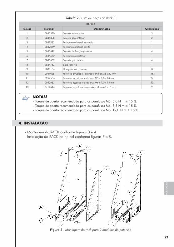
Tabela 2 - Lista de peças do Rack 3
RACK 3
Posição Material Denominação Quantidade
1 10883330 Suporte frontal drive 3
2 10884898 Reforço base inferior 2
3 10881923 Fechamento lateral esquerdo 1
4 10882019 Fechamento lateral direito 1
5 10883499 Suporte de fixação posterior 4
6 10884510 Fechamento posterior 1
7 10883439 Suporte guia inferior 6
8 10884757 Base rack fixo 1
9 10888136 Pino guia rosca interna 12
10 10051025 Parafuso arruelado sextavado phillips M8 x 20 mm 18
11 10254506 Parafuso escariado fenda cruz M5 x 0,8 x 14 mm 24
12 10050963 Parafuso escariado fenda cruz M6 x 1,0 x 16 mm 53
13 10412546 Parafuso arruelado sextavado phillips M6 x 16 mm 9
NOTAS! - Torque de aperto recomendado para os parafusos M5: 5,0 N.m ± 15 %.- Torque de aperto recomendado para os parafusos M6: 8,5 N.m ± 15 %.- Torque de aperto recomendado para os parafusos M8: 19,0 N.m ± 15 %.
4. INSTALAÇÃO
- Montagem do RACK conforme figuras 3 e 4.- Instalação do RACK no painel conforme figuras 7 e 8.
Figura 3 - Montagem do rack para 2 módulos de potência

22
PO
RTU
GU
ÊS
Figura 4 - Montagem do rack para 3 módulos de potência
Figura 5 - Inserção dos módulos de potência no Rack 2

23
PO
RTU
GU
ÊS
Figura 6 - Inserção dos módulos de potência no Rack 3

24
PO
RTU
GU
ÊS
Figura 7 - Detalhes de montagem do Rack 2 em painel com 600 mm de largura

25
PO
RTU
GU
ÊS
Figura 8 - Detalhes de montagem do Rack 3 em painel com 1000 mm de largura

Doc
umen
t: 10
0005
3033
0 /
00
WEG Automação S.A. Jaraguá do Sul - SC Phone 55 (47) 3276-4000 - Fax 55 (47) 3276-4020São Paulo - SP Phone 55 (11) 5053-2300 - Fax 55 (11) [email protected]