1
Progress Update on the Carbon-dioxide Absorber Retrofit Equipment (CARE)
Program Andrew Awtry, Principal Investigator
Ryan Sears, Program Manager Cameron Andersen, Sr. Engineer

Performance Breakthroughs Proprietary Jets
Parameter Benefit
High flat jet specific surface area: as >1000 m2/m3; High overall volumetric mass transfer kinetics, 10 x KLas over conventional systems
High process efficiency; Greatly reduced column footprints; Reduced column/orifice manufacturing and lead time costs
Low ∆PGas ~ 0.03 psi/ft; Low ∆PLiq = <10 psi
Reduced hydrodynamic/ auxiliary power
Aerodynamic shaped jets Reduced liquid entrainment in the gas flow
Factory fabrication of modular/serviceable units
Standardization/lower cost fabrication; Rapid scaling per customer needs

NeuStream®-C Absorber Size Comparison
3
NeuStream® Absorbers: CO2, FGD, Polish and Amine Wash ~ 54,000 ft3
Commercial Carbon Capture System SO2 and CO2 Absorber Towers ~ 306,000 ft3
> 80% decrease in absorber size!

CARE Program Project Objectives
• Design and fabricate 0.5 MW system • Minimize parasitic power through efficient
design • Demonstrate
– 2 month steady-state operation with Multi-Stage Absorber and Innovative Stripper
– 90% CO2 capture efficiency utilizing best available solvent (piperazine at 8m)
• Show unit traceability/scalability to commercial scale – Final TEA
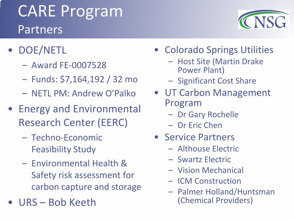
CARE Program Partners
• DOE/NETL – Award FE-0007528 – Funds: $7,164,192 / 32 mo – NETL PM: Andrew O’Palko
• Energy and Environmental Research Center (EERC) – Techno-Economic
Feasibility Study – Environmental Health &
Safety risk assessment for carbon capture and storage
• URS – Bob Keeth
• Colorado Springs Utilities – Host Site (Martin Drake
Power Plant) – Significant Cost Share
• UT Carbon Management Program – Dr Gary Rochelle – Dr Eric Chen
• Service Partners – Althouse Electric – Swartz Electric – Vision Mechanical – ICM Construction – Palmer Holland/Huntsman
(Chemical Providers)

CARE System Design Process Flow Diagram
• NSG flat jets are incorporated into the FGD, Polishing FGD, CO2 Absorbers, Amine Wash, and Stripper

CARE System Enclosure
Enclosure (with insulation) installed around the test stand
Climate Controlled • Conc Pz Solvent
Limit Access Hazard Containment
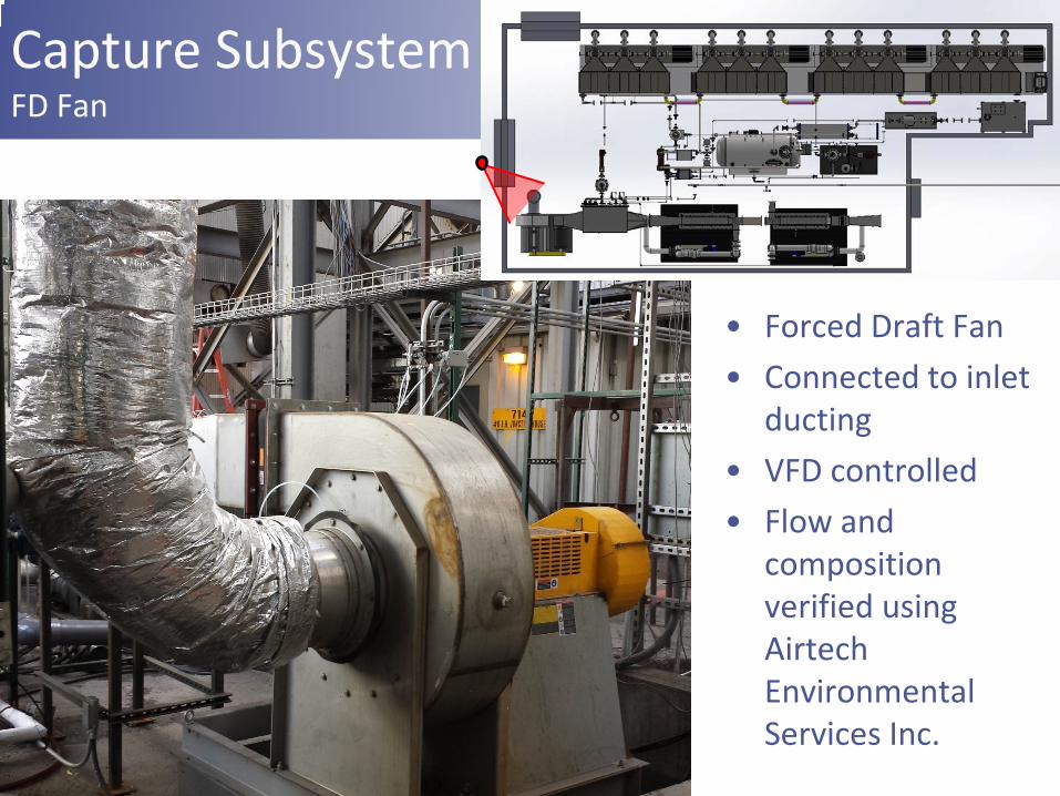
Capture Subsystem FD Fan
• Forced Draft Fan • Connected to inlet
ducting • VFD controlled • Flow and
composition verified using Airtech Environmental Services Inc.

Capture Subsystem FGHR HEXs
• Flue Gas Heat Extraction • Re-Heat HEXs used to bring
flue gas to representative temperature (350oF)
• Steam from electric boiler produces heat

Capture Subsystem FGHR HEXs
• Flue Gas Heat Extraction
• Solvent HEXs extract heat and offset steam use
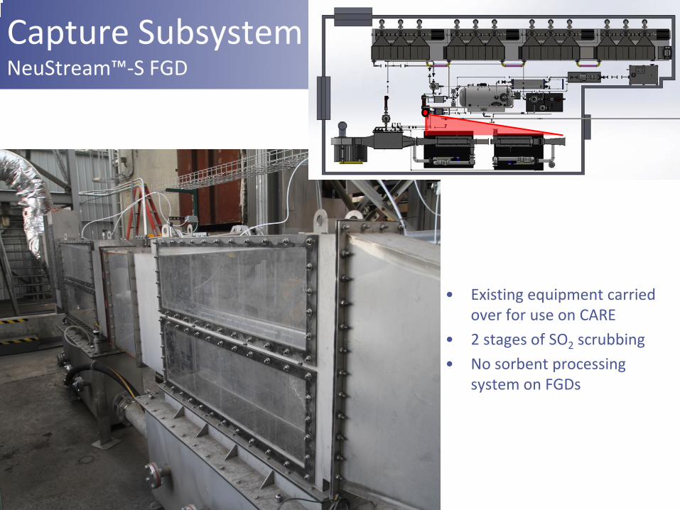
Capture Subsystem NeuStream™-S FGD
• Existing equipment carried over for use on CARE
• 2 stages of SO2 scrubbing • No sorbent processing
system on FGDs

Capture Subsystem Ducting to CO2 Absorbers
• Ducting to CO2 absorbers
• Connects FGD mist eliminator to CO2 absorbers

Absorber Module Absorber Design
Parameter Value Units
Stage Width 58.4 (23)
cm (in)
Stage Height 30.5 (12)
cm (in)
Stage as 440 m2/m3
Stage Length 2.75 (108.3)
m (in)
Capture Efficiency 90% Number of Stages 12
13
30.5 cm
4x Absorbers at 2.75 m each = 11 m Total Length
Total Length = 7.6m as = 440 m2/m3
Lean = 0.28 Rich = 0.38 Liquid Transfer = 42 gpm Flue Gas = 1150 scfm

Absorber Module 90% Capture of 0.6MW
14
• At CSU’s Drake: 2300 SCFM/MW, 12.5% CO2 and 0.8 atm requires 11 meters with 12 stages to get the necessary 2.2 sec residence time
• Using NETL Case 9/10: 2007 SCFM/MW, 13.5% CO2 and 1 atm requires 7.6 meters with 12 stages to get the necessary 2.2 sec residence time

Capture Subsystem CO2 Absorber Train

Capture Subsystem Absorbers
• (1 of 4) Single Absorber Module
• Three stages incorporated into design
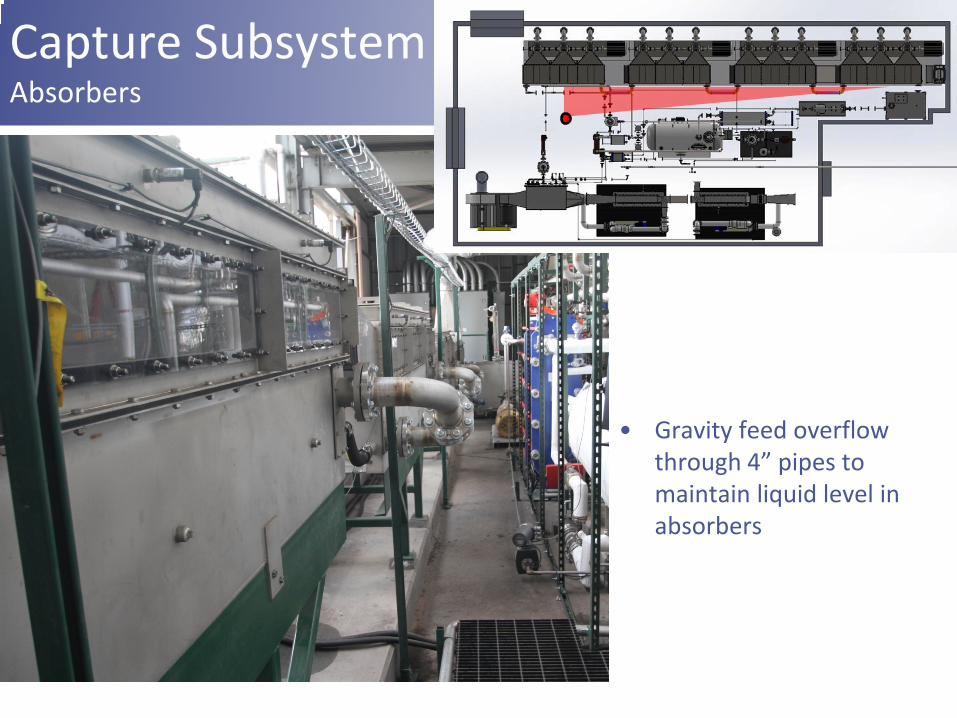
Capture Subsystem Absorbers
• Gravity feed overflow through 4” pipes to maintain liquid level in absorbers

Capture Subsystem Amine Wash
• Existing test stand that required some slight modifications (plumbing changed from PVC to stainless)
• Expected reduction of Amine slip to <1ppm

Capture Subsystem Rich Overflow Tank and Pump
• Absorber 4 – overflows into the rich overflow tank
• The rich overflow tank is a solvent holdup vessel for the system
• Rich pump pulls from rich overflow tank and pushes solvent through the cross HEX to the Stripper
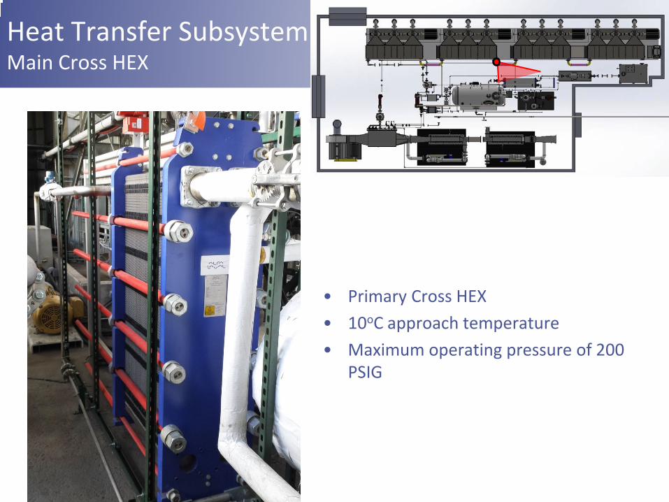
Heat Transfer Subsystem Main Cross HEX
• Primary Cross HEX • 10oC approach temperature • Maximum operating pressure of 200
PSIG
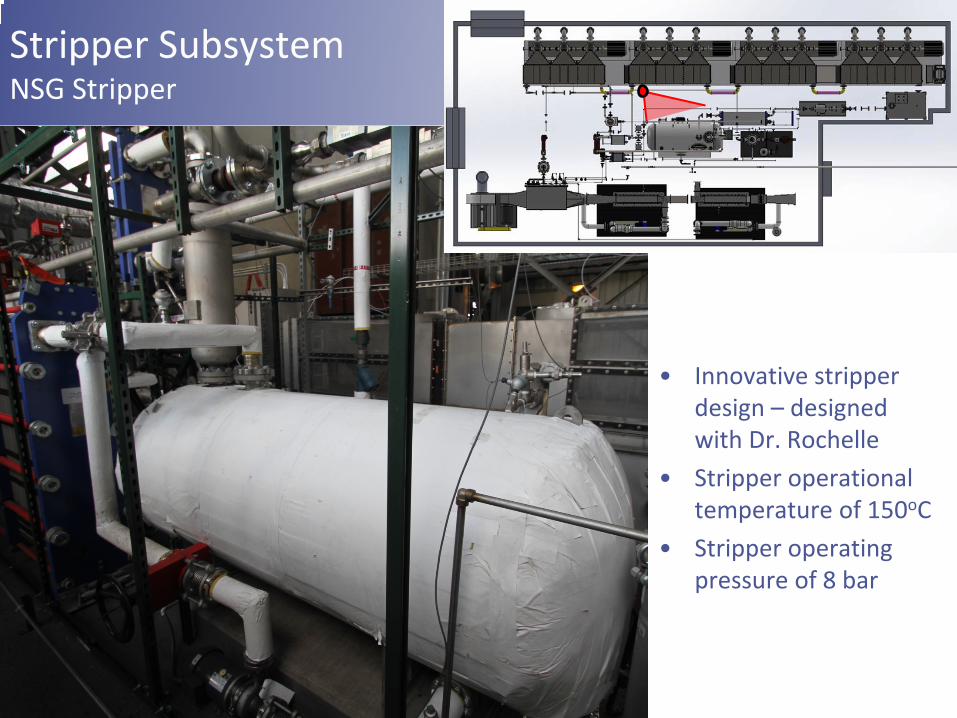
Stripper Subsystem NSG Stripper
• Innovative stripper design – designed with Dr. Rochelle
• Stripper operational temperature of 150oC
• Stripper operating pressure of 8 bar
Mar – April Check Out Testing • Validated performance of all major components • Check out testing on single stages with various
nozzle configurations – Validation of previous small scale DVT work – Tested new nozzles – Tested various configurations of the nozzles
• Verify sensor performance via mass balance closures – Solvent working capacity vs Absorber capture
efficiency vs Stripper outlet (Mass Flow)
22

May 1, 2014 Test Data • 0.5MW gas flow through the CARE System • 6m Piperazine solvent • Lean Loading: 0.28 mol CO2/mol Alk
– 8bar Stripper Pressure – 150C Stripper Temperature
• 90% capture efficiency based on flue gas monitors • 88% capture efficiency based on working capacity
of the solvent • Preliminary Results… System Not Optimized
23
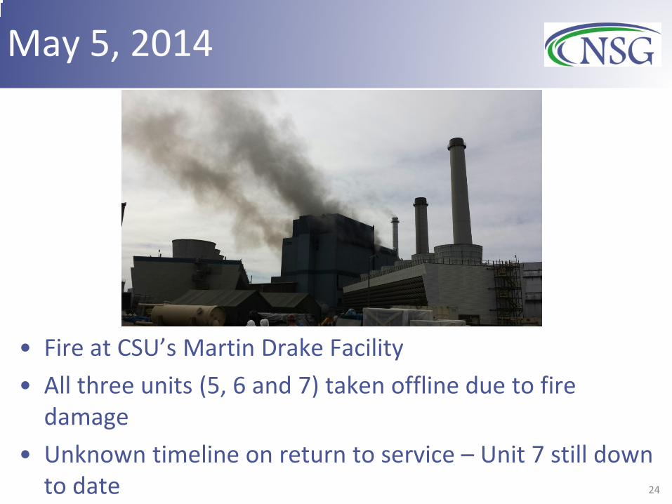
May 5, 2014
• Fire at CSU’s Martin Drake Facility • All three units (5, 6 and 7) taken offline due to fire
damage • Unknown timeline on return to service – Unit 7 still down
to date 24

Revised BP3 Objectives
• Move system to NSG facility – Move ¾ of the absorbers – Simplify the system (no FGD, NOx Control, Flue Gas Heat
integration) – Run on simulated Coal Flue gas (NG boiler with CO2 recycle)
• Improve NSG Technology to further drive down costs through lower parasitic power – Bench Scale R&D – Promising technologies are integrated into the LARGER scale
• Demonstrate capture with multiple (≥3) solvents – Solvent agnostic technology
• Update System Cost for TEA at close of BP3
25
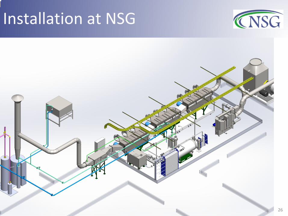
Installation at NSG
26

Installation at NSG
27

Installation at NSG
28

Technology Development Test Stand • ~100 kW size
– Single stage absorber – 10-20% Carbon Capture Efficiency – Capture and regeneration
capability
• Solvent Testing – Needs 50gal – First Approx. on Performance – CO2 Solutions, Piperazine tested
• Can’t share CO2 Solutions’ data per confidentiality agreement
• Technology Testing – Multiple Nozzles and Nozzle
Configurations – as ~ 800 m2/m3 achieved – Working on design to increase jet
length from 12” to 36” at high as
29

CAREtoo System Test Plan/Schedule • June-Nov: Bench Scale Testing on Technology and Solvents • Aug-Sept: Acceptance/Shakedown testing of CAREtoo • Sept-Nov: Integrating and testing technology
improvements • Oct-Jan: Solvent Testing (2-3 weeks per)
– Concentrated piperazine (6m-7m) – CO2 Solution’s Solvent – Monoethanolamine (MEA) – Any others?
• Jan: Program Closeout (BP4 - move back to Drake for completion of original objectives)

CARE NSG’s Carbon Capture Pilot Program
Dr Andrew Awtry Principal Investigator [email protected] (719) 247-8519
Dr Ryan Sears Program Manager [email protected] (719) 247-8510
Dr Jean-Philippe Feve VP Business Development [email protected] (719) 247-8532