Power Scaling of High-Efficiency, Tm-doped Fiber Lasers
Peter F. MoultonQ-Peak, Inc.
SPRC 2008 Annual SymposiumSeptember 17th
Stanford UniversityPalo Alto, CA

Outline
• Background• Fundamentals of Tm:silica fiber lasers• Fiber laser setup and results• Application to laser accelerators
Support:
HEL-JTO Contract No. FA9451-06-D-0009
Technical work:
Q-Peak: Evgueni Slobodtchikov, Kevin Wall, Glen RinesNufern: Gavin Frith, Bryce Samson, Adrian Carter

Relative eye safety is obtained for > 1400-nm wavelengths
Retinal focusing can increase the power density by 105

Rare-earth laser transitions can provide eyesafe wavelengths in fibers
Ener
gy (w
aven
umbe
r/100
00)
1080 nm
1950- 2050 nm
1550 nm
1060 nm930 nm

Tm-ion cross relaxation allows excitation of two upper laser levels for one pump photon
Prior work with Tm:YAG lasers
E.C. Honea, R.J. Beach, S.B. Sutton, J. A. Speth, S.C. Mitchell, J.A. Skidmore, M.A. Emanuel, and S.A. Payne, “115-
W Tm:YAG
Diode-Pumped Solid-State Laser,”
J. Quantum Electron. 33, 1592 (1997).
K. S. Lai, P. B. Phua, R. F. Wu, Y. L. Lim, E. Lau, S. W. Toh, B. T. Toh, and A. Chng, "120-W continuous-wave diode-pumped Tm:YAG
laser ," Opt. Lett. 25, 1591-1593 (2000)
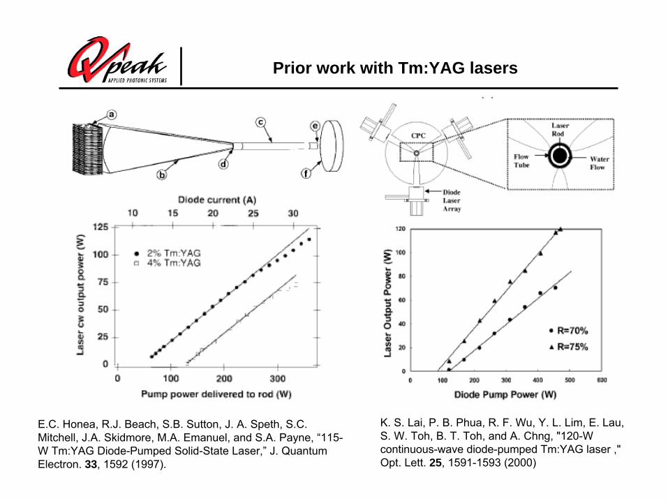
Recent advances in Tm-doped fiber-laser efficiencies show levels approaching Yb fibers
0
10
20
30
40
50
60
70
80
90
100
1995 2000 2005 2010Date
Slop
e Ef
ficie
ncy
(%) 2:1 limit

Recent work: efficient, high-power Tm-doped fiber lasers
G. Frith, D.G. Lancaster and S.D. Jackson, “85 W Tm3+-
doped silica fibre laser,”
Electron. Lett. 41, 1207 (2005).
D.Y. Shen, J.L. Mackenzie, J.K. Sahu, W.A. Clarkson and S.D. Jackson, “High-power and ultra-efficient operation of a Tm3+-
doped silica fiber laser,”
OSA Topical Meeting on Advanced Solid State Photonics, 2005 (Vienna), Paper MC-6.
J. Wu, Z. Yao, I. Zong
and S. Jiang, “Highly Efficient High Power Thulium Doped Germanate Glass Fiber Laser, “
Opt. Lett. 32, 638 (2007
Also: Nufern, 100 W Tm:silica laser

Ho:YLF MOPA chain produces record for hybrid system with Tm:fiber pumps
Tm-fiber laser120 W
Ho-osc
Ho-Amp #1
Tm-fiber laser110 W
Ho-Amp #2
Ho-Amp #3
Tm-fiber laser100 W
Ho-Amp#4
Ho-Amp #5
CW 500 Hz 1000 Hz
Master osc 19 W 25 mJ 17 mJ
Amp 1 42 W 55 mJ 38 mJ
Amp 2 60W 90 mJ 58 mJ
Amp 3 78 W 115 mJ 73 mJ
Amp 4 97 W *** ***
Amp 5 113 W *** ***
*** work in progress
Used IPG fiber lasers that in-band pumped by Yb, Er fiber lasers and are <10% efficient, overall
Note: IPG has scaled this design to 405 W.
Fundamentals of Tm:silica fiber lasers

Absorption and emission cross sections for Tm:silica
0.0E+00
5.0E-22
1.0E-21
1.5E-21
2.0E-21
2.5E-21
3.0E-21
3.5E-21
4.0E-21
4.5E-21
5.0E-21
1400 1500 1600 1700 1800 1900 2000 2100 2200 2300
Wavelength (nm)
Cro
ss s
ectio
n (c
m2)
AbsorptionEmission
Abs: NufernEm: Walsh (NASA)
Abs: NufernEm: Walsh (NASA)

Plot of net gain cross section in Tm:silica vs. inversion fraction
-5E-21
-4E-21
-3E-21
-2E-21
-1E-21
0
1E-21
2E-21
3E-21
4E-21
5E-21
1500 1600 1700 1800 1900 2000 2100 2200
Wavelength (nm)
Net
gai
n cr
oss
sect
ion
(cm
2)
1
0.9
0.8
0.7
0.6
0.5
0.4
0.3
0.2
0.1
0.05
Data on emission cross section from Walsh and absorption cross sections from Nufern

Tm:silica gain at low inversions
-2E-22
-1.5E-22
-1E-22
-5E-23
0
5E-23
1E-22
1.5E-22
1900 1920 1940 1960 1980 2000 2020 2040 2060 2080 2100 2120 2140 2160 2180 2200
Wavelength (nm)
Net
gai
n cr
oss
sect
ion
(cm
2)
0.1
0.09
0.08
0.07
0.06
0.05
0.04
0.03
0.02
0.01
Net gain cross sections needed for 5-m fiber length, with gain of 25

Polished preforms and sample holder

Absorbance data from Lambda 9 measurements
0
0.05
0.1
0.15
0.2
0.25
0.3
600 650 700 750 800 850
Wavelength (nm)
Abs
orba
nce
HILO
Result:LO: 2.03-2.36 wt% (Tm2 O3 )HI: 2.47-2.87 wt%
Result:LO: 2.03-2.36 wt% (Tm2 O3 )HI: 2.47-2.87 wt%

Retiring the photodarkening issue?
0
5000
10000
15000
20000
25000
30000
35000
40000
Ener
gy (c
m-1
)
3H6
3F4
3H5
3H4
3F2,3
1G4
1D2
1I63P03P1
3P2
790-nmpump
M.M. Broer, D.M. Krol and D.J. DiGiovanni, “Highly nonlinear near-resonant photodarkening
in a thulium-doped aluminosilicate
glass fiber,”
Opt. Lett. 18, 799 (1993).

Dynamics measurements of Tm:silica
800-nm emission

Decay data for 3F4 (upper laser) level shows two-lifetime dynamics
0
10000
20000
30000
40000
50000
60000
0.0 0.5 1.0 1.5 2.0 2.5 3.0 3.5 4.0
Time (msec)
Sign
al (a
rb. u
nits
)
LO data broadband
Double exponential fit
633 usec lifetime
281 usec lifetime

Initial portion of 3F4 signal shows feeding from pumped level
0
10000
20000
30000
40000
50000
60000
0.000 0.005 0.010 0.015 0.020 0.025 0.030 0.035 0.040
Time (msec)
Sign
al (a
rb. u
nits
)

800-nm fluorescence provides data on cross-relaxation efficiency
0
10000
20000
30000
40000
50000
60000
0 10 20 30 40 50 60 70 80 90 100
Time (microseconds)
Sign
al le
vel (
arb.
uni
ts)
LO sample
HI sample
5.6 usec to 1/e
7.9 usec to 1/e
Decay in tail: 24.3 usec (LO), 21.0 usec (HI)
Assuming 45 usec lifetime for low Tm doping, efficiency of cross relaxation:
74% for LO80% for HI

Scaling issues for Tm-doped fibers compared to Yb-doped fibers
NAa
o 2V
a is core radius, is wavelength
V < 2.405 for single-mode fiber
Optical damage fluence (dielectric breakdown): scales as l
Raman gain: scales as 1/ l
Brillouin gain: scales as 1/ (l)2 x 1/linewidth
Thus, for the same V parameter, compared to Yb-doped fibers,Tm-doped fibers have:
8 X higher fiber end-facet damage threshold
8X higher stimulated Raman scattering threshold
TBD higher stimulated Brillouin scattering threshold

Fiber laser setup and results

Approach to scaling follows on work done by SOTON on Yb:fiber lasers
Diode stack@975 nm, 1.2 kW
Double-clad Yb-doped fibre
HT @975 nmHR @~1.1 m
Signal output@~1.1 mHT @975 nm
HR @~1.1 m
Diode stack@975 nm, 0.6 kW
HT @975 nmHR @~1.1 m
0.0 0.2 0.4 0.6 0.8 1.0 1.2 1.4 1.6 1.80.0
0.2
0.4
0.6
0.8
1.0
1.2
1.4
Slope efficiency: 83%
Sig
nal p
ower
[kW
]
Launched pump powwer [kW]
Measured Linear fit

Details of the 790-nm pump band (2 wt. % Tm) showing broad absorption
0
1
2
3
4
5
6
7
750 760 770 780 790 800 810 820 830 840 850
Wavelength (nm)
Atte
nuat
ion
(dB
/m)

350-W Laserline pump laser (1 of 2)
Rack unit with diodes, power supply and cooler
5-m delivery fiber
High-power connector
1:1 lens focusing optics

Pump laser wavelengths were 795 nm at full power
Spectral emission data for pump lasers #1 and #2, respectively at a drive current of 55A, approximately 350 W of power output.

Q-Peak fiber-laser testbed
powermeter
Pump Laser A
Pump Laser B
focusinghead
Meniscus2.5-cm R concave surface
HR at 2050 nmHT at 790 nm
Dichroicmirror
HR at 2050 nmHT at 790 nm
clamp
Heat sink
clamp
Active fiber coil
focusinghead
2050 nm output
793-nm pump400-um, 0.2 NAfiber delivery
Single-ended pump

LMA HI2 fiber design used undoped, spliced ends
Fiber assembly: 5-m length of Tm-doped fiber (3), with two undoped, 3-m-long fibers (1) fusion-spliced (2) to the ends of the doped fiber
Gain fiber: LMA HI2Cores: 25 m in diameter, NA: 0.08.Pump claddings: 400-m in diameter, octagonal cross sectionPump attenuation: 2.9 dB/m
x21
3
x12

Results with 350-W pump lasers, LMA HI2 fiber
0
25
50
75
100
125
150
175
200
225
250
275
300
325
0 50 100 150 200 250 300 350 400 450 500 550 600
Launched pump power (W)
Out
put p
ower
(W)
LMA HI2 fiber data conduction cooled, new clampsLinear fitLMA HI2 fiber data conduction cooledLinear fitLMA HI2 fiber data water cooledLinear fit
59.1% slope
61.8% slope
301 W
64.5% slope

LMA HI2 fiber laser beam quality close to D.L.
0
500
1000
1500
200 250 300 350 400EP 7290 camera distance (mm)
Bea
m w
idth
( m
)
Horiz. raw dataVert. raw dataHoriz. processed dataVert. processed data
Vert. axis, My2=1.16
Horiz. axis, Mx2=1.21

Tuning of LMA HI2 laser limited on short-wavelength end by high gain
0
2
4
6
8
10
12
14
16
18
20
1960 1980 2000 2020 2040 2060 2080 2100
Wavelength (nm)
Pow
er o
utpu
t (W
)
The laser was pumped from one end with 47 W, and had a 600g/mm Littrow grating as an end mirror
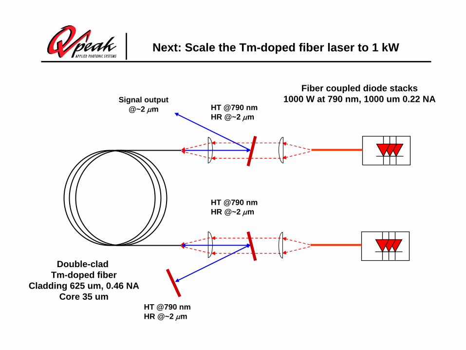
Next: Scale the Tm-doped fiber laser to 1 kW
Fiber coupled diode stacks1000 W at 790 nm, 1000 um 0.22 NA
Double-clad Tm-doped fiber
Cladding 625 um, 0.46 NACore 35 um
HT @790 nmHR @~2 m
HT @790 nmHR @~2 m
Signal output@~2 m
HT @790 nmHR @~2 m
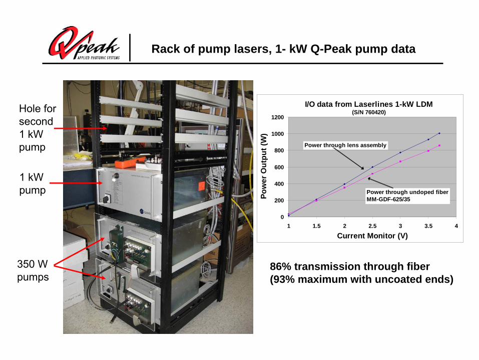
Rack of pump lasers, 1- kW Q-Peak pump data
350 Wpumps
1 kWpump
Hole forsecond
1 kWpump
I/O data from Laserlines 1-kW LDM(S/N 760420)
0
200
400
600
800
1000
1200
1 1.5 2 2.5 3 3.5 4
Current Monitor (V)
Pow
er O
utpu
t (W
)
Power through undoped fiberMM-GDF-625/35
Power through lens assembly
86% transmission through fiber (93% maximum with uncoated ends)

New world’s record for Tm:fiber power
0
100
200
300
400
500
600
700
800
900
1000
0 250 500 750 1000 1250 1500 1750 2000
Launched pump power (W)
Out
put p
ower
(W)
Fiber 2
Fiber 1
51% slope
885 W @ 50.7% efficiency

Application to laser accelerators

Motivation
• The maximum energy generated by conventional, microwave- driven electron accelerators is starting to reach a practical limit imposed by size, either in circumference for storage rings, or in length for linear accelerators. The logical evolution for increasing the energy of linear accelerators (or decreasing their size for the same energy) is to increase the acceleration field. By substituting lasers for microwave sources, one can obtain both higher peak powers and also, because of the ability to focus the much more tightly, much smaller beam areas. The net result in increased intensity is that an accelerating field of, say, a 1 TW, 1000-nm laser can exceed that of a 100 MW, 10-cm microwave source by 7 orders-of-magnitude

Design for laser-based electron accelerator
www.slac.stanford.edu/grp/arb/Byer.pdf

Dielectric structure for accelerator
With an index of ~3.5, a good thermal conductivity and availability silicon would appear to be an ideal choice for the dielectric, however its
transparency range requires the use of λ~2μm lasers that at present are not a mature technology. (PFM – never mind!)
SLAC-PUB-12143 October 2006 Proposed few-optical cycle laser–driven particle
accelerator structure T. Plettner, P. Lu and R.L. Byer
E.L. Ginzton Laboratories, Stanford University, Stanford, CA 94305

Conclusions
• Tm:silica fiber lasers may provide power levels and efficiencies approaching that of Yb:silica fibers
• We have measured some fundamental properties of Tm:silica to better understand laser operation
• With a 25/35/400 Tm:silica fiber laser, we generated 301 W, with 60% conversion of launched pump power to laser output
• The laser slope efficiency indicates that each pump photon generates 1.8 laser photons
• With a 35/625 Tm:silica laser we have, in preliminary results, generated 885 W of power, a new record for this technology
• Potential use for electron accelerators would enable Si dielectric structures, among other possibilities

Backup

Calculation of net gain in Tm:silica fiber laser
We define the inversion fraction as: F = N2 / (N2 + N1), where N1 and N2 are the inversion densities for the lower and upper Tm:silica laser levels. The net gain (or loss) cross section () in the fiber as a function of wavelength, , is given by the relation: () = F e () – (1-F) a (), where e () and a () are the emission and absorption cross sections. The gain or loss coefficient is () multiplied by the concentration of active ions.

Atmospheric transmission over 5-km path shows 90% transmission in 2.035-2.04 m region
0.0
0.1
0.2
0.3
0.4
0.5
0.6
0.7
0.8
0.9
1.0
1.94 1.96 1.98 2 2.02 2.04 2.06 2.08 2.1 2.12
Wavelength (um)
Tran
smis
sion
CO2
HITRAN-PC calculation, standard atmosphere
CO2 and H2 O

Characteristics of Nufern-supplied fibers
Fiber ID MM-TDF-20/400-LO
MM-TDF-20/400-Hi
LMA-20/35/400-Hi
Core diameter 17-23m 17-23m 17-23m Clad diameter 385-415m 385-415m 385-415m Core NA (effective) 0.2 0.2 0.1 Cladding NA 0.46 0.46 0.46 V value at 2m >6 >6 <4 # of modes (2m) 7 7 2 Cladding absorption (795nm)
~2dB/m ~2.6dB/m ~2.6dB/m
Tm-concentration 2.7wt% 3.5wt% 3.5wt% Cladding Shape Octagon Octagon Octagon
At 790.1 nm (2.5-nm linewidth) we measured 1.09 db/m for LO fiber (10-m length)and 1.54 db/m for HI fiber (7-m length)


![Nanoparticle-doped electrospun fiber random lasers with ... · [2,6,8,10]. Organic crystals [16,17] and epitaxial nanowires [18], biopolymers [19,20], as well as conjugated polymers](https://static.cupdf.com/doc/110x72/600d3d88f8e5ef616721ea08/nanoparticle-doped-electrospun-fiber-random-lasers-with-26810-organic.jpg)


![JOURNAL - tu-plovdiv.bg- 6 - and studied such mode of operation for the two modern lasers - CW diode-pumped Yb-doped crystal lasers and the CW red diode lasers [7-9].](https://static.cupdf.com/doc/110x72/5e6fd350b25a843bd51ea44f/journal-tu-6-and-studied-such-mode-of-operation-for-the-two-modern-lasers.jpg)


![Nanoparticle-doped electrospun fiber random lasers with ...nanojets.unisalento.it/published/Resta OptExp 2017.pdfdescribable as a diffusive process [6,11], with a characteristic photon](https://static.cupdf.com/doc/110x72/5ecfab5ec2ae7629b312715c/nanoparticle-doped-electrospun-fiber-random-lasers-with-optexp-2017pdf-describable.jpg)