


01/17/2015 277844 - HPL-ED2014 V9.0 EN 1 / 13
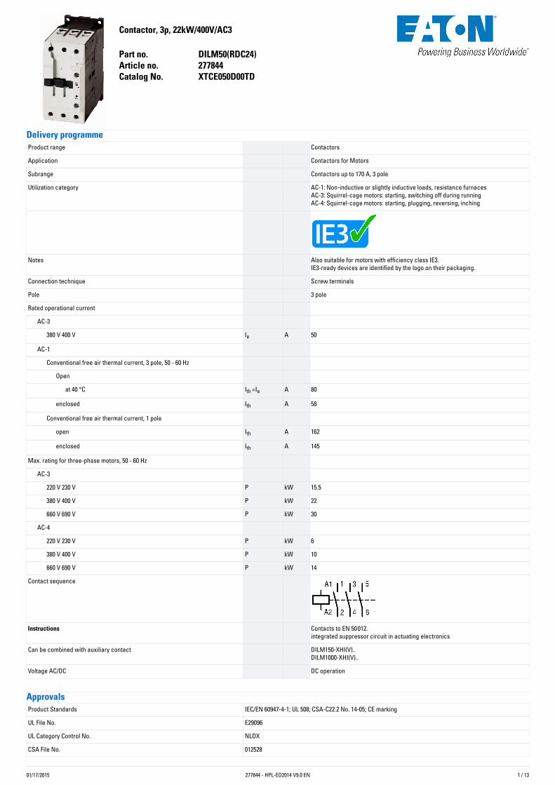
Contactor,3p,22kW/400V/AC3
Partno. DILM50(RDC24)Articleno. 277844CatalogNo. XTCE050D00TD
DeliveryprogrammeProduct range Contactors
Application Contactors for Motors
Subrange Contactors up to 170 A, 3 pole
Utilization category AC-1: Non-inductive or slightly inductive loads, resistance furnacesAC-3: Squirrel-cage motors: starting, switching off during runningAC-4: Squirrel-cage motors: starting, plugging, reversing, inching
Notes Also suitable for motors with efficiency class IE3.IE3-ready devices are identified by the logo on their packaging.
Connection technique Screw terminals
Pole 3 pole
Rated operational current
AC-3
380 V 400 V Ie A 50
AC-1
Conventional free air thermal current, 3 pole, 50 - 60 Hz
Open
at 40 °C Ith =Ie A 80
enclosed Ith A 58
Conventional free air thermal current, 1 pole
open Ith A 162
enclosed Ith A 145
Max. rating for three-phase motors, 50 - 60 Hz
AC-3
220 V 230 V P kW 15.5
380 V 400 V P kW 22
660 V 690 V P kW 30
AC-4
220 V 230 V P kW 6
380 V 400 V P kW 10
660 V 690 V P kW 14
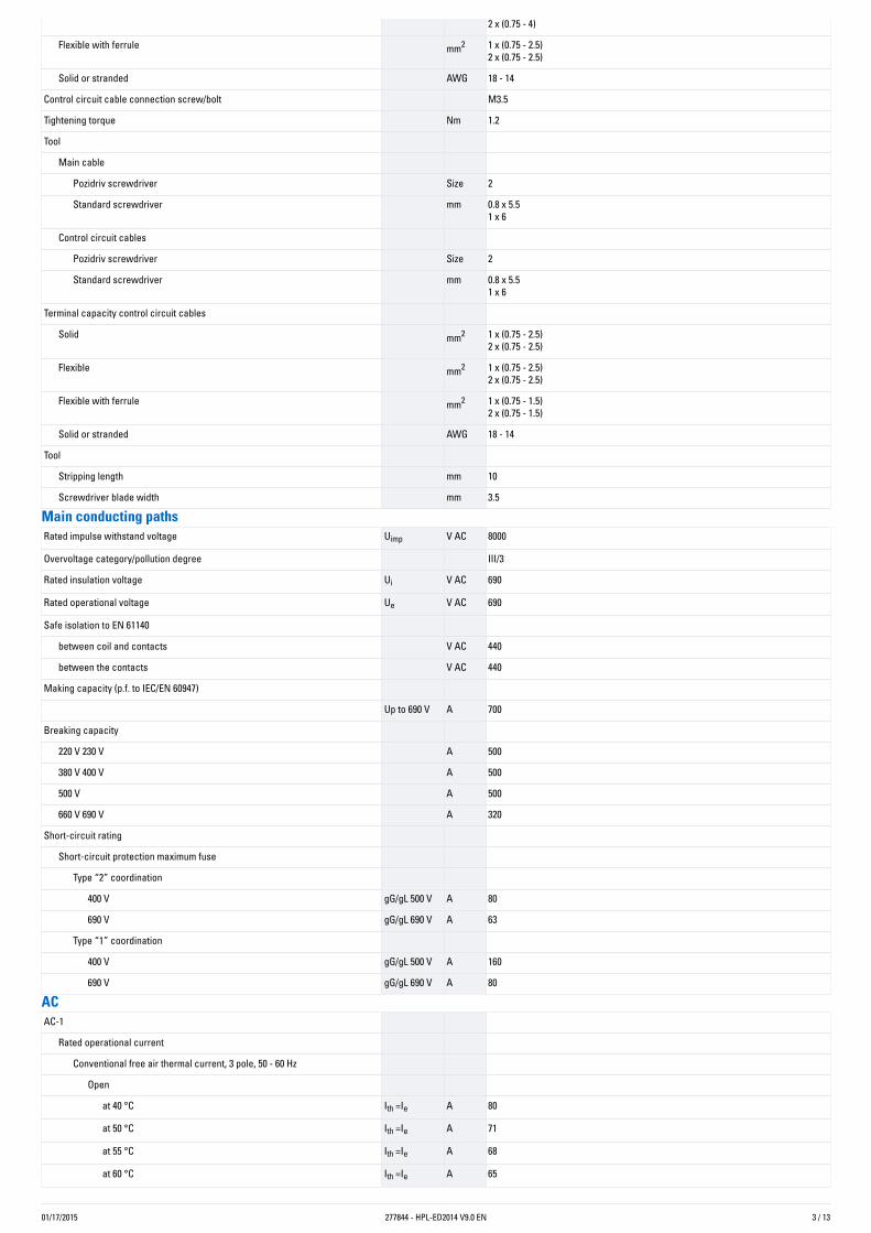
Contact sequence
Instructions Contacts to EN 50 012.integrated suppressor circuit in actuating electronics
Can be combined with auxiliary contact DILM150-XHI(V)..DILM1000-XHI(V)..
Voltage AC/DC DC operation
ApprovalsProduct Standards IEC/EN 60947-4-1; UL 508; CSA-C22.2 No. 14-05; CE marking
UL File No. E29096
UL Category Control No. NLDX
CSA File No. 012528
01/17/2015 277844 - HPL-ED2014 V9.0 EN 2 / 13
CSA Class No. 2411-03, 3211-04
North America Certification UL listed, CSA certified
Specially designed for North America No
GeneralStandards IEC/EN 60947, VDE 0660, UL, CSA
Lifespan, mechanical
AC operated Operations x 106 10
DC operated Operations x 106 10
Operating frequency, mechanical
AC operated Operations/h 5000
DC operated Operations/h 5000
Climatic proofing Damp heat, constant, to IEC 60068-2-78Damp heat, cyclic, to IEC 60068-2-30
Ambient temperature °C
Open °C - 25 - 60
Enclosed °C - 25 - 40
Storage °C - 40 - 80
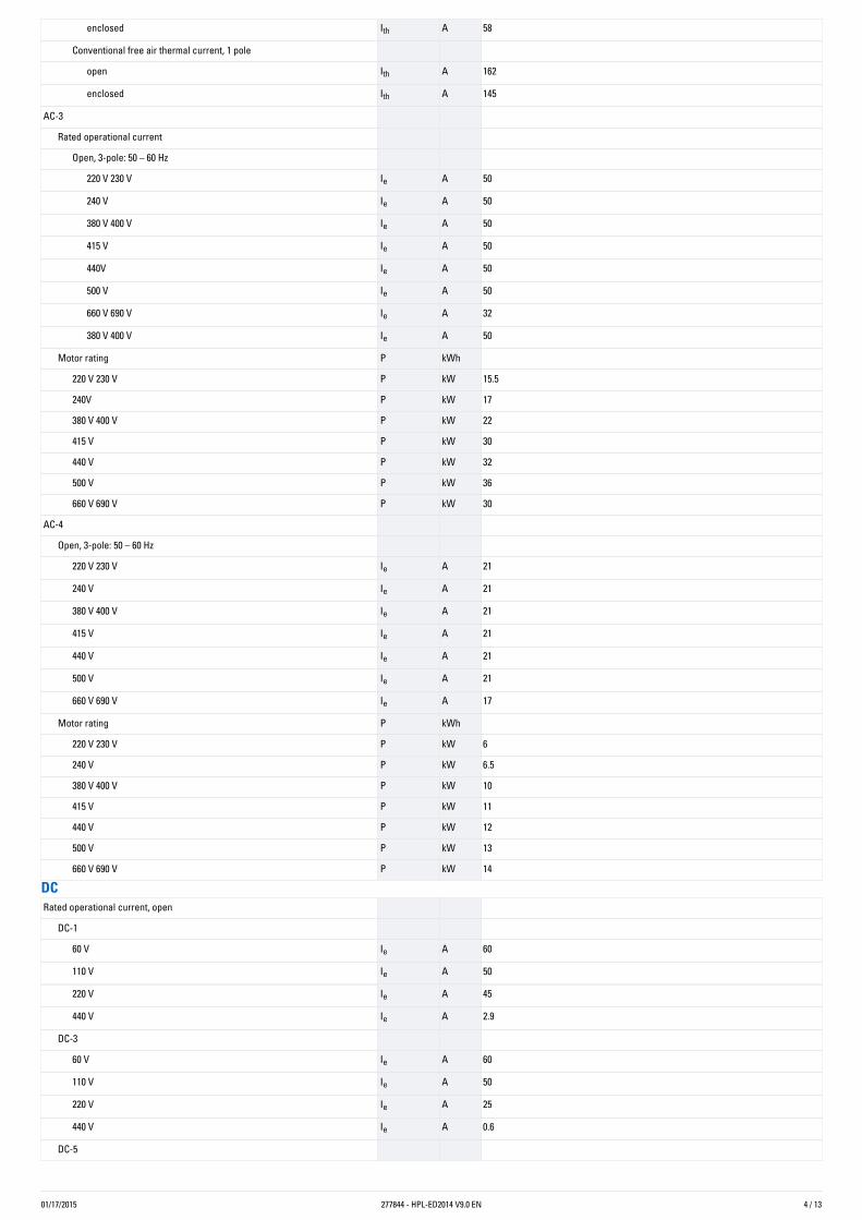
Mounting position
Mechanical shock resistance (IEC/EN 60068-2-27)
Half-sinusoidal shock, 10 ms
Main contacts
N/O contact g 10
Auxiliary contacts
N/O contact g 7
N/C contact g 5
Mechanical shock resistance (IEC/EN 60068-2-27) when tabletop-mounted
Half-sinusoidal shock, 10 ms
Main contacts
N/O contact g 10
Auxiliary contacts
N/O contact g 7
N/C contact g 5
Degree of Protection IP00
Protection against direct contact when actuated from front (EN 50274) Finger and back-of-hand proof
Weight
AC operated kg 0.9
DC operated kg 1.1
Terminal capacity main cable
Solid mm2 1 x (0.75 - 16)2 x (0.75 - 16)
Flexible with ferrule mm2 1 x (0.75 - 35)2 x (0.75 - 25)
Stranded mm2 1 x (16 - 50)2 x (16 - 35)
Solid or stranded AWG 12 - 2
Flat conductor Lamellenzahlx Breite xDicke
mm 2 x (6 x 9 x 0.8)
Main cable connection screw/bolt M6
Tightening torque Nm 3.3
Terminal capacity control circuit cables
Solid mm2 1 x (0.75 - 4)
01/17/2015 277844 - HPL-ED2014 V9.0 EN 3 / 13
2 x (0.75 - 4)
Flexible with ferrule mm2 1 x (0.75 - 2.5)2 x (0.75 - 2.5)
Solid or stranded AWG 18 - 14
Control circuit cable connection screw/bolt M3.5
Tightening torque Nm 1.2
Tool
Main cable
Pozidriv screwdriver Size 2
Standard screwdriver mm 0.8 x 5.51 x 6
Control circuit cables
Pozidriv screwdriver Size 2
Standard screwdriver mm 0.8 x 5.51 x 6
Terminal capacity control circuit cables
Solid mm2 1 x (0.75 - 2.5)2 x (0.75 - 2.5)
Flexible mm2 1 x (0.75 - 2.5)2 x (0.75 - 2.5)
Flexible with ferrule mm2 1 x (0.75 - 1.5)2 x (0.75 - 1.5)
Solid or stranded AWG 18 - 14
Tool
Stripping length mm 10
Screwdriver blade width mm 3.5
MainconductingpathsRated impulse withstand voltage Uimp V AC 8000
Overvoltage category/pollution degree III/3
Rated insulation voltage Ui V AC 690
Rated operational voltage Ue V AC 690
Safe isolation to EN 61140
between coil and contacts V AC 440
between the contacts V AC 440
Making capacity (p.f. to IEC/EN 60947)
Up to 690 V A 700
Breaking capacity
220 V 230 V A 500
380 V 400 V A 500
500 V A 500
660 V 690 V A 320
Short-circuit rating
Short-circuit protection maximum fuse
Type “2” coordination
400 V gG/gL 500 V A 80
690 V gG/gL 690 V A 63
Type “1” coordination
400 V gG/gL 500 V A 160
690 V gG/gL 690 V A 80
ACAC-1
Rated operational current
Conventional free air thermal current, 3 pole, 50 - 60 Hz
Open
at 40 °C Ith =Ie A 80
at 50 °C Ith =Ie A 71
at 55 °C Ith =Ie A 68
at 60 °C Ith =Ie A 65
01/17/2015 277844 - HPL-ED2014 V9.0 EN 4 / 13
enclosed Ith A 58
Conventional free air thermal current, 1 pole
open Ith A 162
enclosed Ith A 145
AC-3
Rated operational current
Open, 3-pole: 50 – 60 Hz
220 V 230 V Ie A 50
240 V Ie A 50
380 V 400 V Ie A 50
415 V Ie A 50
440V Ie A 50
500 V Ie A 50
660 V 690 V Ie A 32
380 V 400 V Ie A 50
Motor rating P kWh
220 V 230 V P kW 15.5
240V P kW 17
380 V 400 V P kW 22
415 V P kW 30
440 V P kW 32
500 V P kW 36
660 V 690 V P kW 30
AC-4
Open, 3-pole: 50 – 60 Hz
220 V 230 V Ie A 21
240 V Ie A 21
380 V 400 V Ie A 21
415 V Ie A 21
440 V Ie A 21
500 V Ie A 21
660 V 690 V Ie A 17
Motor rating P kWh
220 V 230 V P kW 6
240 V P kW 6.5
380 V 400 V P kW 10
415 V P kW 11
440 V P kW 12
500 V P kW 13
660 V 690 V P kW 14
DCRated operational current, open
DC-1
60 V Ie A 60
110 V Ie A 50
220 V Ie A 45
440 V Ie A 2.9
DC-3
60 V Ie A 60
110 V Ie A 50
220 V Ie A 25
440 V Ie A 0.6
DC-5
01/17/2015 277844 - HPL-ED2014 V9.0 EN 5 / 13
60 V Ie A 60
110 V Ie A 50
220 V Ie A 25
440 V Ie A 0.6
Currentheatloss3-pole at Ith W 19
Current heat loss at Ie to AC-3/400 V W 11.3
Impedance per pole mΩ 1.5
MagnetsystemsVoltage tolerance x Uc
AC operated Pick-up x Uc 0.8 - 1.1
Drop-out voltage AC operated Drop-out x Uc 0.3 - 0.6
Notes RDC 24 (Umin 24 V DC/Umax 27 V DC)Example: Uc = 0.7 x Umin - 1.2 x Umax / Uc = 0.7 x 24 V - 1.2 x 27 V DC
DC operated Pick-up x Uc 0.7 - 1.2
Notes at least smoothed two-phase bridge rectifier or three-phase rectifier
DC operated Drop-out x Uc 0.15 - 0.6
Power consumption of the coil in a cold state and 1.0 x Uc
50 Hz Pick-up VA 149
50 Hz Sealing VA 16
50 Hz Sealing W 4.3
60 Hz Pick-up VA 178
60 Hz Sealing VA 19
60 Hz Sealing W 5.3
50/60 Hz Pick-up VA 168154
50/60 Hz Sealing VA 2214
50/60 Hz Sealing W 5.34.3
DC operated Pick-up W 24
DC operated Sealing W 0.5
Duty factor % DF 100
Switching times at 100 % Uc (approximate values)
Main contacts
AC operated
Closing delay ms 12 - 18
Opening delay ms 8 - 13
DC operated ms
Closing delay ms 54
Opening delay ms 24
Arcing time ms 10
Lifespan, mechanical; Coil 50/60 Hz x 106 Mechanical lifespan at 50 Hz approx. 30% lower than under “Technical data,general”
Electromagneticcompatibility(EMC)Emitted interference to EN 60947-1
Interference immunity to EN 60947-1
DatafordesignverificationaccordingtoIEC/EN61439Technical data for design verification
Rated operational current for specified heat dissipation In A 50
Heat dissipation per pole, current-dependent Pvid W 3.77
Equipment heat dissipation, current-dependent Pvid W 0
Static heat dissipation, non-current-dependent Pvs W 0.5
Heat dissipation capacity Pdiss W 0
IEC/EN 61439 design verification
01/17/2015 277844 - HPL-ED2014 V9.0 EN 6 / 13
10.2 Strength of materials and parts
10.2.2 Corrosion resistance Meets the product standard's requirements.
10.2.3.1 Verification of thermal stability of enclosures Meets the product standard's requirements.
10.2.3.2 Verification of resistance of insulating materials to normal heat Meets the product standard's requirements.
10.2.3.3 Verification of resistance of insulating materials to abnormal heatand fire due to internal electric effects
Meets the product standard's requirements.
10.2.4 Resistance to ultra-violet (UV) radiation Meets the product standard's requirements.
10.2.5 Lifting Does not apply, since the entire switchgear needs to be evaluated.
10.2.6 Mechanical impact Does not apply, since the entire switchgear needs to be evaluated.
10.2.7 Inscriptions Meets the product standard's requirements.
10.3 Degree of protection of ASSEMBLIES Does not apply, since the entire switchgear needs to be evaluated.
10.4 Clearances and creepage distances Meets the product standard's requirements.
10.5 Protection against electric shock Does not apply, since the entire switchgear needs to be evaluated.
10.6 Incorporation of switching devices and components Does not apply, since the entire switchgear needs to be evaluated.
10.7 Internal electrical circuits and connections Is the panel builder's responsibility.
10.8 Connections for external conductors Is the panel builder's responsibility.
10.9 Insulation properties
10.9.2 Power-frequency electric strength Is the panel builder's responsibility.
10.9.3 Impulse withstand voltage Is the panel builder's responsibility.
10.9.4 Testing of enclosures made of insulating material Is the panel builder's responsibility.
10.10 Temperature rise The panel builder is responsible for the temperature rise calculation. Eaton willprovide heat dissipation data for the devices.
10.11 Short-circuit rating Is the panel builder's responsibility. The specifications for the switchgear must beobserved.
10.12 Electromagnetic compatibility Is the panel builder's responsibility. The specifications for the switchgear must beobserved.
10.13 Mechanical function The device meets the requirements, provided the information in the instructionleaflet (IL) is observed.
TechnicaldataETIM5.0Low-voltage industrial components (EG000017) / Magnet contactor, AC-switching (EC000066)
Electric engineering, automation, process control engineering / Low-voltage switch technology / Contactor (LV) / Power contactor, AC switching (ecl@ss8-27-37-10-03 [AAB718011])
Rated control supply voltage Us at AC 50HZ V 0 - 0
Rated control supply voltage Us at AC 60HZ V 0 - 0
Rated control supply voltage Us at DC V 24 - 27
Voltage type for actuating DC
Rated operation current Ie at AC-1, 400 V A 80
Rated operation current Ie at AC-3, 400 V A 50
Rated operation power at AC-3, 400 V kW 22
Rated operation current Ie at AC-4, 400 V A 21
Rated operation power Ie at AC-4, 400 V kW 10
Modular version No
Number of auxiliary contacts as normally open contact 0
Number of auxiliary contacts as normally closed contact 0
Connection type main current circuit Screw connection
Number of normally closed contacts as main contact 0
Number of main contacts as normally open contact 3
01/17/2015 277844 - HPL-ED2014 V9.0 EN 7 / 13
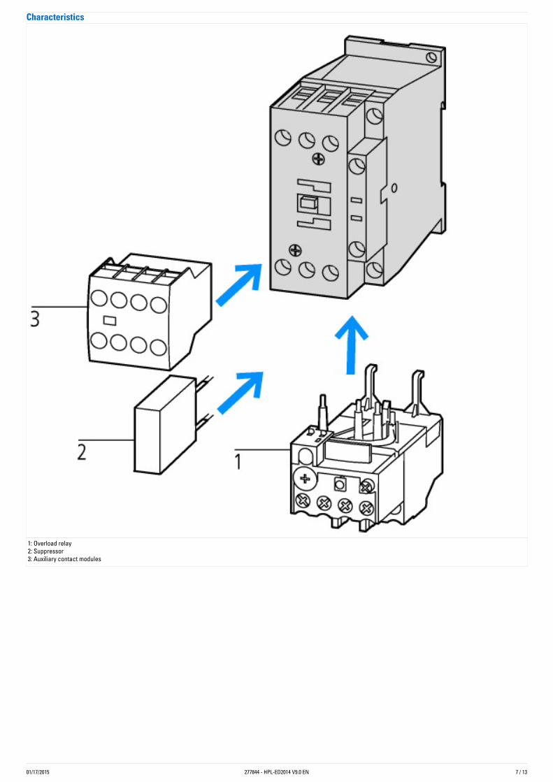
Characteristics
1: Overload relay2: Suppressor3: Auxiliary contact modules
01/17/2015 277844 - HPL-ED2014 V9.0 EN 8 / 13
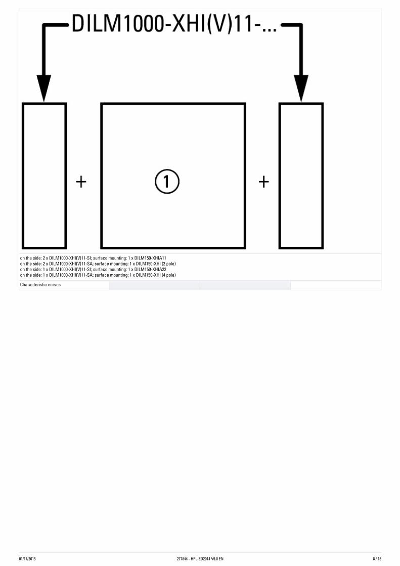
on the side: 2 x DILM1000-XHI(V)11-SI; surface mounting: 1 x DILM150-XHIA11on the side: 2 x DILM1000-XHI(V)11-SA; surface mounting: 1 x DILM150-XHI (2 pole)on the side: 1 x DILM1000-XHI(V)11-SI; surface mounting: 1 x DILM150-XHIA22on the side: 1 x DILM1000-XHI(V)11-SA; surface mounting: 1 x DILM150-XHI (4 pole)
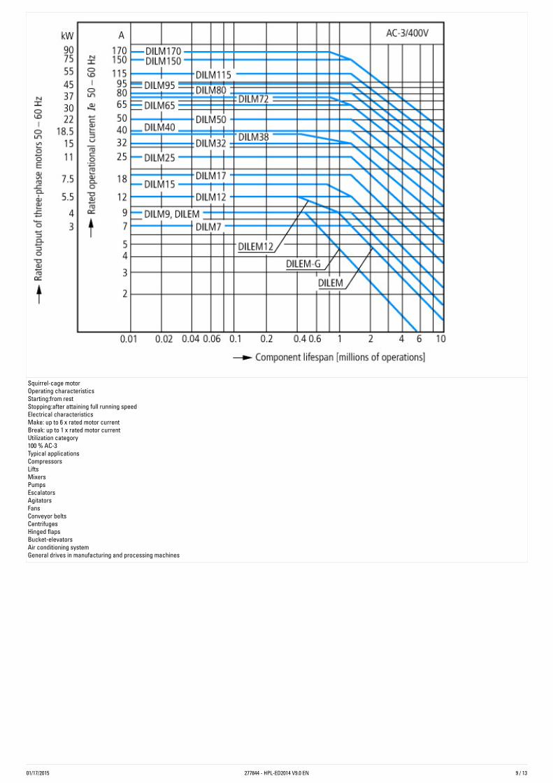
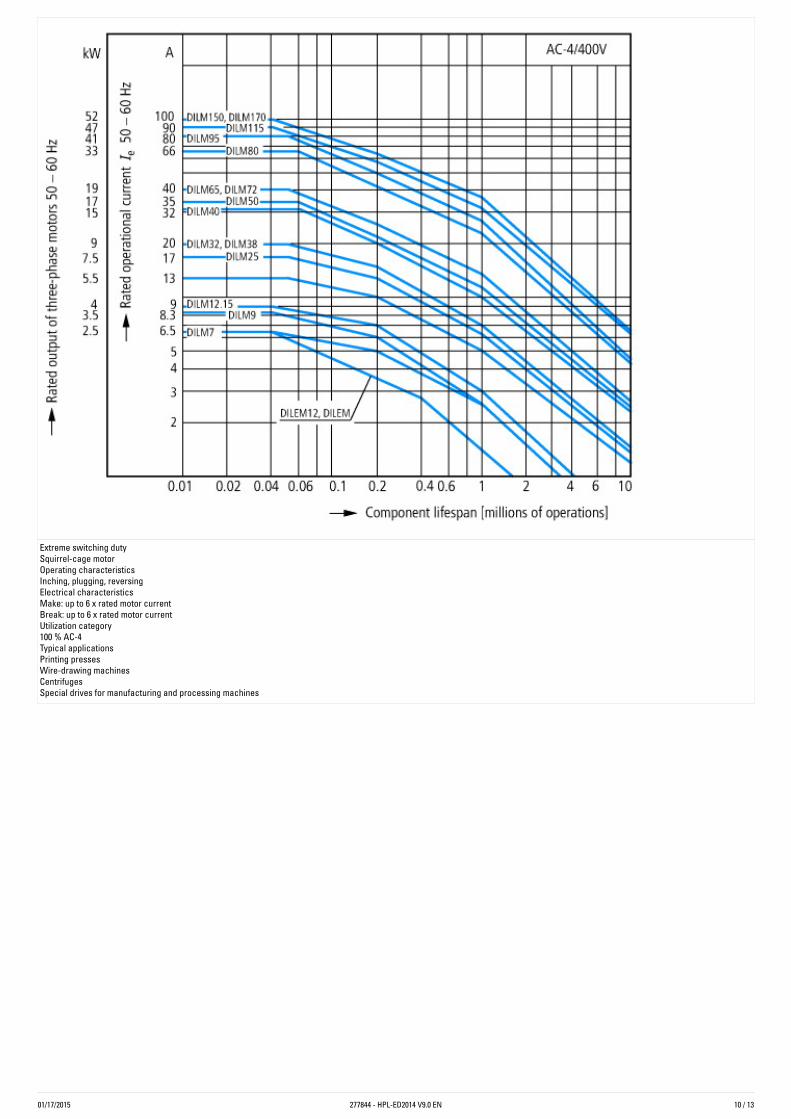
Characteristic curves
01/17/2015 277844 - HPL-ED2014 V9.0 EN 9 / 13
Squirrel-cage motorOperating characteristicsStarting:from restStopping:after attaining full running speedElectrical characteristicsMake: up to 6 x rated motor currentBreak: up to 1 x rated motor currentUtilization category100 % AC-3Typical applicationsCompressorsLiftsMixersPumpsEscalatorsAgitatorsFansConveyor beltsCentrifugesHinged flapsBucket-elevatorsAir conditioning systemGeneral drives in manufacturing and processing machines
01/17/2015 277844 - HPL-ED2014 V9.0 EN 10 / 13
Extreme switching dutySquirrel-cage motorOperating characteristicsInching, plugging, reversingElectrical characteristicsMake: up to 6 x rated motor currentBreak: up to 6 x rated motor currentUtilization category100 % AC-4Typical applicationsPrinting pressesWire-drawing machinesCentrifugesSpecial drives for manufacturing and processing machines
01/17/2015 277844 - HPL-ED2014 V9.0 EN 11 / 13
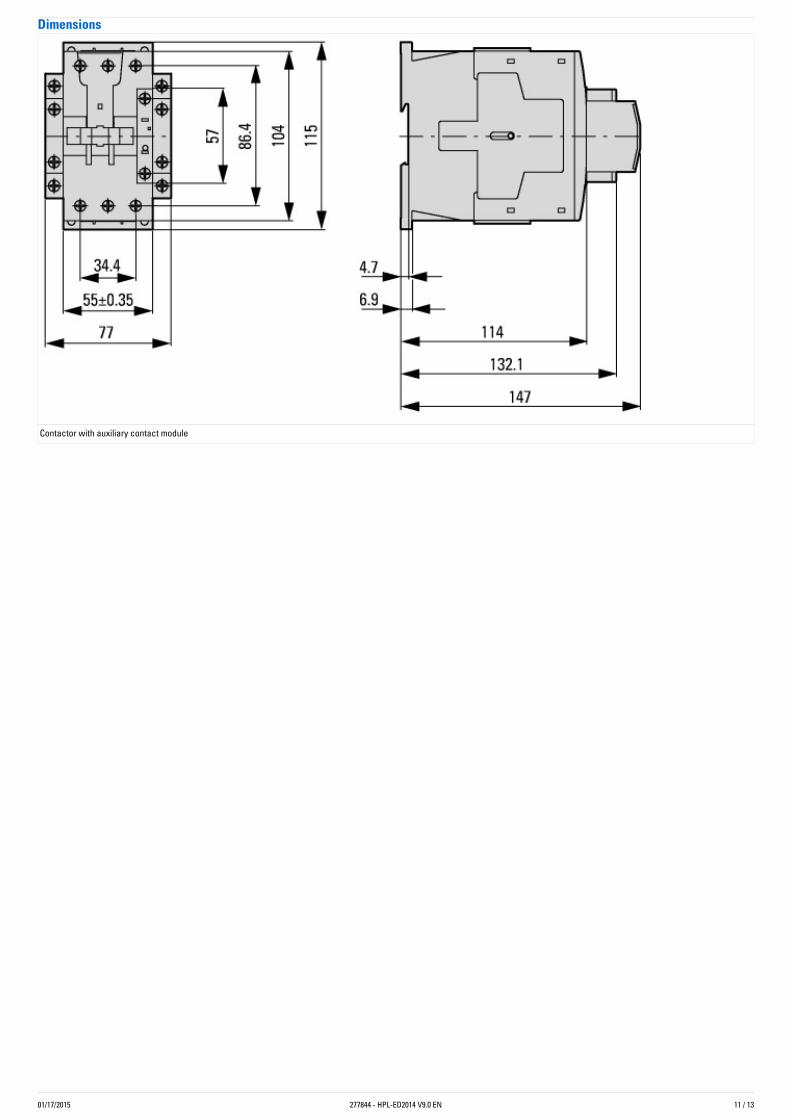
Dimensions
Contactor with auxiliary contact module
01/17/2015 277844 - HPL-ED2014 V9.0 EN 12 / 13
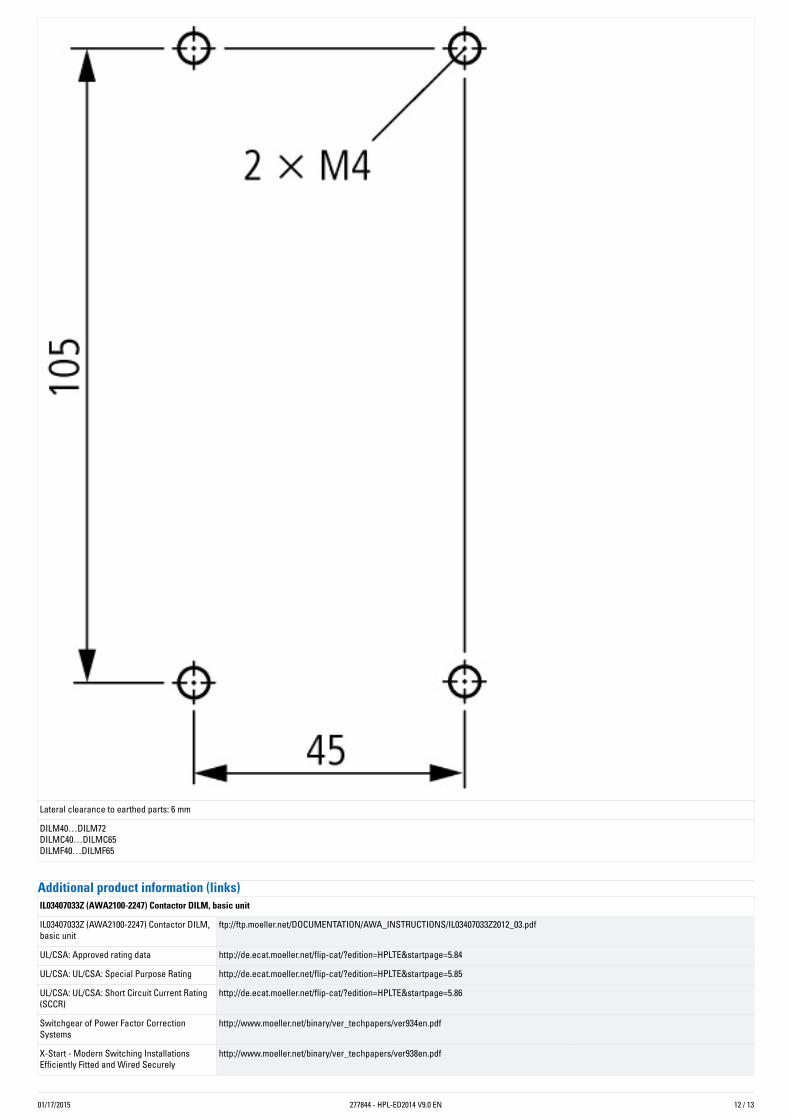
Lateral clearance to earthed parts: 6 mm
DILM40…DILM72DILMC40…DILMC65DILMF40…DILMF65
Additionalproductinformation(links)IL03407033Z(AWA2100-2247)ContactorDILM,basicunit
IL03407033Z (AWA2100-2247) Contactor DILM,basic unit
ftp://ftp.moeller.net/DOCUMENTATION/AWA_INSTRUCTIONS/IL03407033Z2012_03.pdf
UL/CSA: Approved rating data http://de.ecat.moeller.net/flip-cat/?edition=HPLTE&startpage=5.84
UL/CSA: UL/CSA: Special Purpose Rating http://de.ecat.moeller.net/flip-cat/?edition=HPLTE&startpage=5.85
UL/CSA: UL/CSA: Short Circuit Current Rating(SCCR)
http://de.ecat.moeller.net/flip-cat/?edition=HPLTE&startpage=5.86
Switchgear of Power Factor CorrectionSystems
http://www.moeller.net/binary/ver_techpapers/ver934en.pdf
X-Start - Modern Switching InstallationsEfficiently Fitted and Wired Securely
http://www.moeller.net/binary/ver_techpapers/ver938en.pdf
01/17/2015 Eaton Industries GmbHhttp://www.eaton.eu
© 12/2014 by Eaton Industries GmbH277844 - HPL-ED2014 V9.0 EN
13 / 13
Mirror Contacts for Highly-Reliable InformationRelating to Safety-Related Control Functions
http://www.moeller.net/binary/ver_techpapers/ver944en.pdf
Effect of the Cabel Capacitance of Long ControlCables on the Actuation of Contactors
http://www.moeller.net/binary/ver_techpapers/ver949en.pdf
Motor starters and "Special Purpose Ratings"for the North American market
http://www.moeller.net/binary/ver_techpapers/ver953en.pdf
Switchgear for Luminaires http://www.moeller.net/binary/ver_techpapers/ver955en.pdf
Standard Compliant and Functionally SafeEngineering Design with Mechanical AuxiliaryContacts
http://www.moeller.net/binary/ver_techpapers/ver956en.pdf
The Interaction of Contactors with PLCs http://www.moeller.net/binary/ver_techpapers/ver957en.pdf
Busbar Component Adapters for modernIndustrial control panels
http://www.moeller.net/binary/ver_techpapers/ver960en.pdf


