SAFETY
DEFINITIONS______________________________________
•DANGER WILL cause DEATH, SEVERE INJURY or
substantial property damage.
•WARNING CAN cause DEATH, SEVERE INJURY or
substantial property damage.
•CAUTION WILL or CAN cause MINOR INJURY or property
damage.
GENERAL SAFETY PRECAUTIONS __________________
•DANGER INTAKE AIR. Can contain carbon monoxide or
other contaminants. Will cause serious injury or
death. Ingersoll Rand air compressors are not
designed, intended or approved for breathing air.
Compressed air should not be used for breathing
air applications unless treated in accordance
with all applicable codes and regulations.
•WARNING HAZARDOUS VOLTAGE. Can cause serious
injury or death. Disconnect power and bleed
pressure from tank before servicing.
Lockout/Tagout machine. Compressor must be
connected to properly grounded circuit. See
grounding instructions in manual. Do not operate
compressor in wet conditions. Store indoors.
MOVING PARTS. Can cause serious injury. Do
not operate with guards removed. Machine may
start automatically. Disconnect power before
servicing. Lockout/Tagout machine.
HOT SURFACES. Can cause serious injury. Do
not touch. Allow to cool before servicing. Do not
touch hot compressor or tubing.
HIGH PRESSURE AIR. Bypassing, modifying or
removing safety/relief valves can cause serious
injury or death. Do not bypass, modify or remove
safety/relief valves. Do not direct air stream at
body. Rusted tanks can cause explosion and
severe injury or death. Drain tank daily or after
each use. Drain valve located at bottom of tank.
•CAUTION RISK OF BURSTING. Use only suitable air
handling parts acceptable for pressure of not
less than the maximum allowable working
pressure of the machine.
GENERAL INFORMATION
Your air compressor unit is suitable for operating air tools,
caulking guns, grease guns, sandblasters, etc. Depending on
your application, the following accessories may be required:
l An air pressure regulator to adjust the air pressure entering
the tool or accessory.
l An air line filter for removal of moisture and oil vapor in
compressed air.
l An in-line lubricator to prolong the life of air tools.
l Separate air transformers which combine the functions of air
regulation and/or moisture and dirt removal.
Contact your nearest authorized dealer or call 1-800-AIR-SERV
for more information on air tools and accessories for your
application.
PREPARATION FOR USE
TRANSPORTING THE UNIT _________________________
•CAUTION The wheels and handle do not provide adequate
clearance, stability or support for pulling the unit
up and down stairs or steps. The unit must be
lifted or pushed up a ramp. Do not use the handle
to lift the unit.
SELECTING A LOCATION___________________________
GENERAL. Select a clean, dry, well-lighted area with plenty of
space for proper cooling air flow and accessibility. Locate the unit
on a solid level surface at least 12 inches (30 cm) from walls.
Ensure unit is as level as possible.
TEMPERATURE. Ideal operating temperatures are between
32°F and 104°F (0°C and 40°C). In lower temperatures, you must
protect safety/relief valves and drain valves from freezing.
•CAUTION Never operate in temperatures below 20°F
(-6.6°C) or above 125°F (51.0°C).
HUMID AREAS. In frequently humid areas, moisture may form in
the bare pump and produce sludge in the lubricant, causing
running parts to wear out prematurely. Excessive moisture is
especially likely to occur if the unit is located in an unheated area
that is subject to large temperature changes. Two signs of
excessive humidity are external condensation on the bare pump
when it cools down and a “milky” appearance in petroleum
compressor lubricant. You may be able to prevent moisture from
forming in the bare pump by increasing ventilation or operating
for longer intervals.
NOISE CONSIDERATIONS. Consult local officials for
information regarding acceptable noise levels in your area. To
reduce excessive noise, use vibration mounts or intake silencers,
relocate the unit or construct total enclosures or baffle walls.
Contact your dealer for assistance.
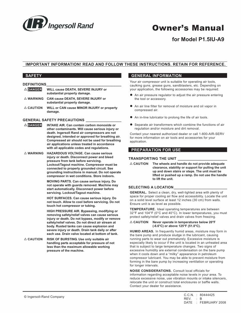
Owner’s Manual
for Model P1.5IU-A9
© Ingersoll-Rand Company
IMPORTANT INFORMATION! READ AND FOLLOW THESE INSTRUCTIONS. RETAIN FOR REFERENCE.
C.C.N. : 80444425
REV. : B
DATE : FEBRUARY 2008

INSTALLING THE AIR INLET FILTER _________________
•CAUTION Do not operate without air inlet filter.
Install the air inlet filters at the inlet connections at the bare
pump. If heavy duty filtration is required, contact your dealer for
information.
INSTALLING DISCHARGE PIPING ___________________
If it is necessary to install air discharge piping or condensate
discharge piping, adhere to the following general guidelines.
Contact your dealer for more information.
•WARNING If an aftercooler, check valve, block valve, or any
other restriction is added to the compressor
discharge, install a properly-sized ASME
approved safety/relief valve between the
compressor discharge and the restriction.
•CAUTION If you will be using All Season Select synthetic
compressor lubricant, all downstream piping
material and system components must be
compatible. Refer to the following material
compatibility list. If there are incompatible
materials present in your system, or if there are
materials not included in the list, contact your
dealer.
Suitable:
Viton®, Teflon®, Epoxy (Glass Filled), Oil Resistant Alkyd,
Fluorosilicone, Fluorocarbon, Polysulfide, 2-Component Urethane,
Nylon, Delrin®, Celcon®, High Nitrile Rubber (Buna N. NBR more than
36% Acrylonitrile), Polyurethane, Polyethylene, Epichlorohydrin,
Polyacrylate, Melamine, Polypropylene, Baked Phenolics, Epoxy,
Modified Alkyds
(® indicates trademark of DuPont Corporation)
Not Recommended:
Neoprene, Natural Rubber, SBR Rubber, Acrylic Paint, Lacquer, Varnish,
Polystyrene, PVC, ABS, Polycarbonate, Cellulose Acetate, Low Nitrile
Rubber (Buna N. NBR less than 36% Acrylonitrile), EPDM, Ethylene
Vinyl Acetate, Latex, EPR, Acrylics, Phenoxy, Polysulfones, Styrene
Acrylonitrile (San), Butyl
GENERAL REQUIREMENTS. The piping, fittings, receiver tank,
etc. must be certified safe for at least the maximum working
pressure of the unit. Use hard-welded or threaded steel or
copper pipes, cast iron fittings and hoses that are certified safe
for the unit’s discharge pressure and temperature. DO NOT USE
PVC PLASTIC. Use pipe thread sealant on all threads, and make
up joints tightly to prevent air leaks.
CONDENSATE DISCHARGE PIPING. If installing a condensate
discharge line, the piping must be at least one size larger than
the connection, as short and direct as possible, secured tightly
and routed to a suitable drain point. Condensate must be
disposed of in accordance with local, state, and federal laws and
regulations.
NOTE: All compressed air systems generate condensate which
accumulates in any drain point (e.g. tanks, filters, drip legs,
aftercoolers, dryers). This condensate contains lubricating oil
and/or substances which may be regulated and must be
disposed of in accordance with local, state, and federal laws and
regulations.
ELECTRICAL WIRING & GROUNDING ________________
•WARNING Any electrical installation and service required
should be performed by a qualified electrician
who is familiar with all applicable local, state and
federal laws and regulations.
GENERAL. The motor rating, as shown on the motor nameplate,
and the power supply must have compatible voltage, phase and
hertz characteristics.
FUSES. Refer to the National Electric Code to determine the
proper fuse or circuit breaker rating required. When selecting
fuses, remember the momentary starting current of an electric
motor is greater than its full load current. Time-delay or
“slow-blow” fuses are recommended.
GROUNDING. The unit is equipped with a power cord having a
grounding wire an an appropriate grounding plug. The plug must
be used with an outlet that has been installed and grounded in
accordance with all local codes and ordinances. The outlet must
have the same configuration as the plug. DO NOT USE AN
ADAPTER.
•WARNING In the event of a short circuit, grounding reduces
the risk of shock by providing an escape for the
electric current. The unit must be properly
grounded.
•DANGER Improper installation of the grounding plug can
result in a risk of electric shock. If repair or
replacement of the cord or plug is necessary, do
not connect the grounding wire to either flat
blade terminal. The wire with insulation having an
outer surface that is green with or without yellow
stripes is the grounding wire.
Check with a qualified electrician or serviceman if the grounding
instructions are not completely understood, or if in doubt as to
whether the product is properly grounded. Do not modify the plug
provided; if it will not fit the outlet, have the proper outlet
installed by a qualified electrician.
This product is for use on a nominal 120-volt circuit and has a
grounding plug that looks like the plug illustrated below. Make
sure the product is connected to an outlet having the same
configuration as the plug. No adapter should be used with this
product.
EXTENSION CORDS. It is preferable to use extra air hose
instead of an extension cord to avoid voltage drop and power
loss to the motor, and to prevent overheating. If an extension
cord must be used, ensure it meets the following criteria:
l Three wire cord with a three blade grounding plug, and a
three slot receptacle that will accept the plug on the unit.
l Good condition
l No longer than 50 feet.
l 12 gauge or larger.
NOTE Wire size increases as gauge number decreases.
For example, 10 AWG and 8 AWG wire is
acceptable, whereas 14 or 16 AWG are NOT
acceptable.
COMPRESSOR LUBRICATION_______________________
•CAUTION Do not operate without lubricant or with
inadequate lubricant. Ingersoll Rand is not
responsible for compressor failure caused by
inadequate lubrication.
SYNTHETIC LUBRICANT. We recommend All Season Select
synthetic compressor lubricant from start-up. See the
WARRANTY section for extended warranty information.
A=Ground
B=Grounding Pin
C=Outlet
2
http://air.irco.com P1.5IU-A9
ALTERNATE LUBRICANTS. You may use a petroleum-based
lubricant that is premium quality, does not contain detergents,
contains only anti-rust, anti-oxidation, and anti-foam agents as
additives, has a flashpoint of 440°F (227°C) or higher, and has
an auto-ignition point of 650°F (343°C) or higher.
See the petroleum lubricant viscosity table below. The table is
intended as a general guide only. Heavy duty operating
conditions require heavier viscosities. Refer specific operating
conditions to your dealer for recommendations.
Temperature Around Unit Viscosity @ 100°F
(37.8°C)
Viscosity Grade
°F °C SUS Centistoke
s
ISO SAE
40 & below 4.4 & below 150 32 32 10
40 - 80 4.4 - 26.7 500 110 100 30
80 - 125 26.7 - 51.0 750 165 150 40
If you use a petroleum-based compressor lubricant at start-up
and decide to convert to All Season Select synthetic compressor
lubricant later on, the compressor valves must be thoroughly
decarbonized and the crankcase must be flushed before
conversion.
COMPRESSOR PUMP FILLING PROCEDURES:
•WARNING HAZARDOUS VOLTAGE. Can cause serious
injury or death. Disconnect power and
Lockout/Tagout machine.
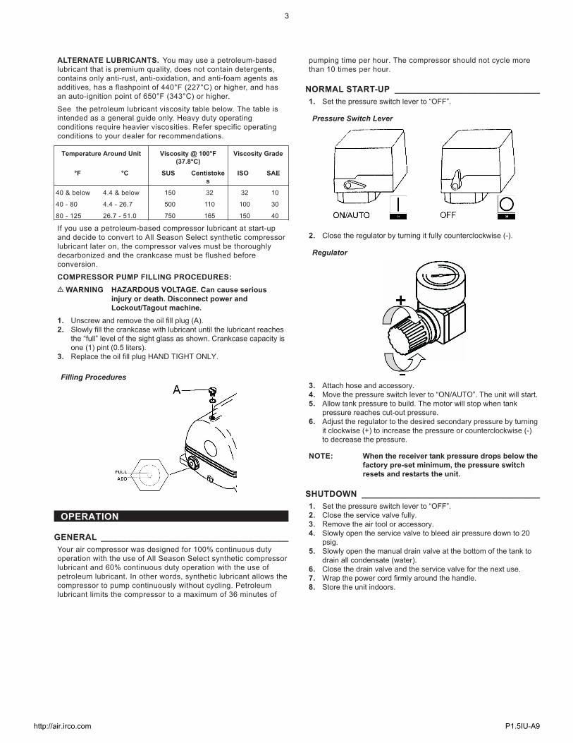
1. Unscrew and remove the oil fill plug (A).
2. Slowly fill the crankcase with lubricant until the lubricant reaches
the “full” level of the sight glass as shown. Crankcase capacity is
one (1) pint (0.5 liters).
3. Replace the oil fill plug HAND TIGHT ONLY.
OPERATION
GENERAL ________________________________________
Your air compressor was designed for 100% continuous duty
operation with the use of All Season Select synthetic compressor
lubricant and 60% continuous duty operation with the use of
petroleum lubricant. In other words, synthetic lubricant allows the
compressor to pump continuously without cycling. Petroleum
lubricant limits the compressor to a maximum of 36 minutes of
pumping time per hour. The compressor should not cycle more
than 10 times per hour.
NORMAL START-UP _______________________________
1. Set the pressure switch lever to “OFF”.
2. Close the regulator by turning it fully counterclockwise (-).
3. Attach hose and accessory.
4. Move the pressure switch lever to “ON/AUTO”. The unit will start.
5. Allow tank pressure to build. The motor will stop when tank
pressure reaches cut-out pressure.
6. Adjust the regulator to the desired secondary pressure by turning
it clockwise (+) to increase the pressure or counterclockwise (-)
to decrease the pressure.
NOTE: When the receiver tank pressure drops below the
factory pre-set minimum, the pressure switch
resets and restarts the unit.
SHUTDOWN ______________________________________
1. Set the pressure switch lever to “OFF”.
2. Close the service valve fully.
3. Remove the air tool or accessory.
4. Slowly open the service valve to bleed air pressure down to 20
psig.
5. Slowly open the manual drain valve at the bottom of the tank to
drain all condensate (water).
6. Close the drain valve and the service valve for the next use.
7. Wrap the power cord firmly around the handle.
8. Store the unit indoors.
Filling Procedures
Pressure Switch Lever
Regulator
3
http://air.irco.com P1.5IU-A9
MAINTENANCE
•WARNING Unplug the unit and release air pressure from the
tank before performing maintenance.
•WARNING Wear appropriate personal safety equipment
such as safety glasses and gloves.
NOTE All compressed air systems contain maintenance
parts (e.g. lubricating oil, filters, separators)
which are periodically replaced. These used
parts may be, or may contain, substances that
are regulated and must be disposed of in
accordance with local, state, and federal laws
and regulations.
NOTE Take note of the positions and locations of parts
during disassembly to make reassembly easier.
The assembly sequences and parts illustrated
may differ for your particular unit.
NOTE Follow engine owner’s manual for engine
maintenance schedules and procedures.
NOTE Any service operations not included in this
section should be performed by an authorized
service representative.
ROUTINE MAINTENANCE SCHEDULEDaily or Before
Each Operationl Check lubricant level. Fill as needed.
l Drain receiver tank condensate. Open the
manual drain valve and collect and dispose
of condensate accordingly.
l Check for unusual noise and vibration.
l Ensure and covers are securely in place.
l Ensure area around compressor is free
from rags, tools, debris, and flammable or
explosive materials.Weekly l Inspect air filter element. Clean or replace
if necessary.Monthly l Inspect for air leaks. Squirt soapy water
around joints during compressor operation
and watch for bubbles.
l Check tightness of screws and bolts.
Tighten as needed.
l Clean exterior.3/500 * l Change petroleum lubricant while
crankcase is warm.12/2000 * l Change synthetic lubricant while crankcase
is warm.
l Replace filter element.
* indicates months/operating hours, whichever occurs first.
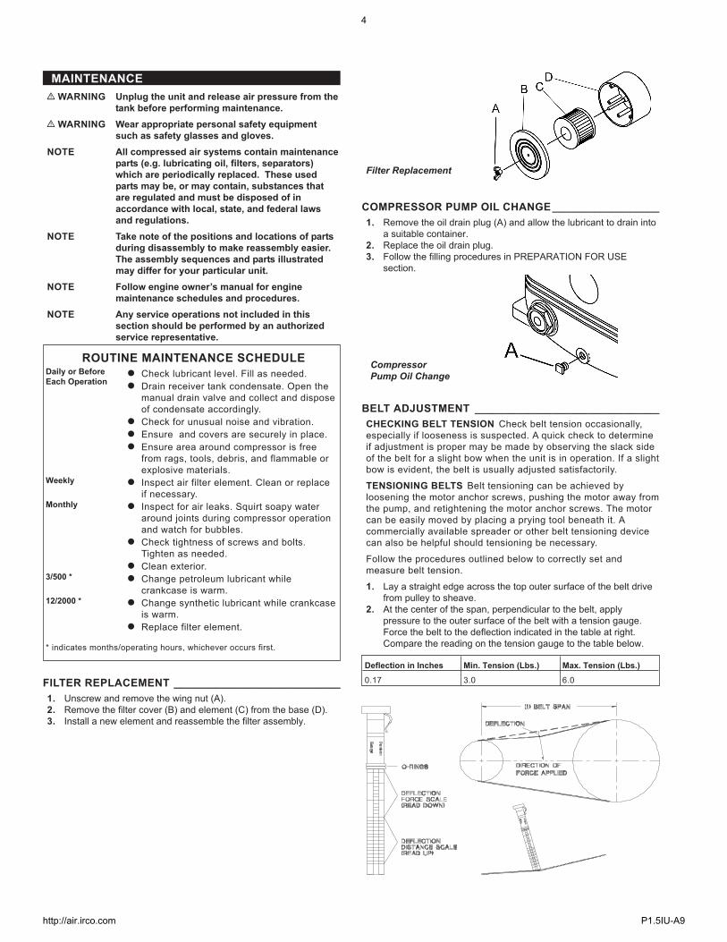
FILTER REPLACEMENT ____________________________
1. Unscrew and remove the wing nut (A).
2. Remove the filter cover (B) and element (C) from the base (D).
3. Install a new element and reassemble the filter assembly.
COMPRESSOR PUMP OIL CHANGE__________________
1. Remove the oil drain plug (A) and allow the lubricant to drain into
a suitable container.
2. Replace the oil drain plug.
3. Follow the filling procedures in PREPARATION FOR USE
section.
BELT ADJUSTMENT _______________________________
CHECKING BELT TENSION Check belt tension occasionally,
especially if looseness is suspected. A quick check to determine
if adjustment is proper may be made by observing the slack side
of the belt for a slight bow when the unit is in operation. If a slight
bow is evident, the belt is usually adjusted satisfactorily.
TENSIONING BELTS Belt tensioning can be achieved by
loosening the motor anchor screws, pushing the motor away from
the pump, and retightening the motor anchor screws. The motor
can be easily moved by placing a prying tool beneath it. A
commercially available spreader or other belt tensioning device
can also be helpful should tensioning be necessary.
Follow the procedures outlined below to correctly set and
measure belt tension.
1. Lay a straight edge across the top outer surface of the belt drive
from pulley to sheave.
2. At the center of the span, perpendicular to the belt, apply
pressure to the outer surface of the belt with a tension gauge.
Force the belt to the deflection indicated in the table at right.
Compare the reading on the tension gauge to the table below.
Deflection in Inches Min. Tension (Lbs.) Max. Tension (Lbs.)
0.17 3.0 6.0
Filter Replacement
Compressor
Pump Oil Change
4
http://air.irco.com P1.5IU-A9

Ensure the pulley and sheave are properly aligned and the motor
anchor screws are adequately retightened prior to restarting the
compressor.
•CAUTION Improper pulley/sheave alignment and belt
tension can result in motor overload, excessive
vibration, and premature belt and/or bearing
failure.
To prevent these problems from occurring,
ensure the pulley and sheave are aligned and belt
tension is satisfactory after installing new belts
or tensioning existing belts.
TANK INSPECTION ________________________________
The life of an air receiver tank is dependent upon several factors
including, but not limited to, operating conditions, ambient
environments, and the level of maintenance. The exact effect of
these factors on tank life is difficult to predict; therefore, Ingersoll
Rand recommends that you schedule a certified tank inspection
within the first five years of compressor service. To arrange a
tank inspection, contact the nearest Ingersoll Rand Customer
Center or distributor, or call 1-800-AIR SERV.
If the tank has not been inspected within the first 10 years of
compressor service, the receiver must be taken out of service
until it has passed inspection. Tanks that fail to meet
requirements must be replaced.
•WARNING Failure to replace a rusted air receiver tank could
result in air receiver tank rupture or explosion,
which could cause substantial property damage,
severe personal injury, or death. Never modify or
repair tank. Obtain replacement from service
center.
5
http://air.irco.com P1.5IU-A9

TROUBLESHOOTING
PROBLEM POSSIBLE CAUSE POSSIBLE SOLUTION
Abnormal piston, ring or cylinder
wear
1. Lubricant viscosity too low.
2. Lubricant level too low.
3. Detergent type lubricant being used.
4. Cylinder(s) or piston(s) scratched, worn or scored.
5. Extremely dusty atmosphere.
6. Worn cylinder finish.
1. Drain existing lubricant and refill with proper lubricant.
2. Add lubricant to crankcase to proper level.
3. Drain existing lubricant and refill with proper lubricant.
4. Repair or replace as required.
5. Install remote air inlet piping and route to source of
cleaner air. Install more effective filtration.
6. Deglaze cylinder with 180 grit flex-hone.
Air delivery drops off 1. Clogged or dirty inlet and/or discharge line filter.
2. Air leaks in air discharge piping.
3. Lubricant viscosity too high.
4. Compressor valves leaky, broken, carbonized or loose.
5. Piston rings damaged or worn (broken, rough or
scratched). Excessive end gap or side clearance.
6. Piston rings not seated, are stuck in grooves or end gaps
not staggered.
7. Cylinder(s) or piston(s) scratched, worn or scored.
8. Defective safety/relief valve.
1. Clean or replace.
2. Check tubing and connections.
3. Drain existing lubricant and refill with proper lubricant.
4. Inspect valves. Clean or replace as required. Install valve
kit.
5. Install ring kit.
6. Adjust piston rings.
7. Repair or replace as required.
8. Replace.
Unit does not come up to speed 1. Loose beltwheel or motor pulley, excessive end play in
motor shaft or loose drive belts.
2. Lubricant viscosity too high.
3. Improper line voltage.
4. Compressor valves leaky, broken, carbonized or loose.
5. Defective ball bearings on crankshaft or motor shaft.
1. Check beltwheel, motor pulley, crankshaft, drive belt
tension and alignment. Repair or replace as required.
2. Drain existing lubricant and refill with proper lubricant.
3. Check line voltage and upgrade lines as required.
Contact electrician.
4. Inspect valves. Clean or replace as required.
Install valve kit.
5. Inspect bearings and replace crankshaft assembly if
required.
Unit is slow to come up to speed 1. Lubricant viscosity too high.
2. Leaking check valve or check valve seat blown out.
3. Ambient temperature too low.
4. Bad motor.
1. Drain existing lubricant and refill with proper lubricant.
2. Replace check valve.
3. Relocate unit to warmer environment.
Install crankcase heater kit.
4. Replace.
Unit runs excessively hot 1. Inadequate ventilation around beltwheel.
2. Drive belts too tight or misaligned.
3. Compressor valves leaky, broken, carbonized or loose.
4. Wrong beltwheel direction of rotation.
1. Relocate unit for better air flow.
2. Adjust belts to proper tension and alignment.
3. Inspect valves. Clean or replace as required. Install valve
kit.
4. Check motor wiring for proper connections. Reverse two
leads on three-phase motors.
Excessive noise during
operation
1. Loose beltwheel or motor pulley, excessive end play in
motor shaft or loose drive belts.
2. Lubricant viscosity too high.
3. Lubricant level too low.
4. Compressor valves leaky, broken, carbonized or loose.
5. Carbon build-up on top of piston(s).
6. Defective ball bearings on crankshaft or motor shaft.
7. Leaking check valve or check valve seat blown out.
1. Check beltwheel, motor pulley, crankshaft, drive belt
tension and alignment. Repair or replace as required.
2. Drain existing lubricant and refill with proper lubricant.
3. Add lubricant to crankcase to proper level.
4. Inspect valves. Clean or replace as required.
Install valve kit.
5. Clean piston(s). Repair or replace as required.
6. Inspect bearings and replace crankshaft assembly if
required.
7. Replace check valve.
Excessive starting and stopping 1. Air leaks in air discharge piping.
2. Pressure switch differential too narrow.
3. Leaking check valve or check valve seat blown out.
4. Excessive condensate in receiver tank.
1. Check tubing and connections.
2. Adjust pressure switch to increase differential, if
differential adjustment is provided. Install pressure switch
with differential adjustment feature if differential
adjustment is desired.
3. Replace check valve.
4. Drain receiver tank with manual drain valve.
High oil consumption 1. Clogged or dirty inlet and/or discharge line filter.
2. Lubricant viscosity too low.
3. Detergent type lubricant being used.
4. Piston rings damaged or worn (broken, rough or
scratched). Excessive end gap or side clearance.
5. Piston rings not seated, are stuck in grooves or end gaps
not staggered.
6. Cylinder(s) or piston(s) scratched, worn or scored.
7. Connecting rod, piston pin or crankpin bearings worn or
scored.
8. Crankshaft seal worn or crankshaft scored.
9. Worn cylinder finish.
1. Clean or replace.
2. Drain existing lubricant and refill with proper lubricant.
3. Drain existing lubricant and refill with proper lubricant.
4. Install ring kit.
5. Adjust piston rings.
6. Repair or replace as required.
7. Inspect all. Repair or replace as required.
8. Replace seal or crankshaft assembly.
9. Deglaze cylinder with 180 grit flex-hone.
Knocking or rattling 1. Loose beltwheel or motor pulley, excessive end play in
motor shaft or loose drive belts.
2. Compressor valves leaky, broken, carbonized or loose.
3. Carbon build-up on top of piston(s).
4. Cylinder(s) or piston(s) scratched, worn or scored.
5. Connecting rod, piston pin or crankpin bearings worn or
scored.
6. Defective ball bearings on crankshaft or motor shaft.
1. Check beltwheel, motor pulley, crankshaft, drive belt
tension and alignment. Repair or replace as required.
2. Inspect valves. Clean or replace as required.
Install valve kit.
3. Clean piston(s). Repair or replace as required.
4. Repair or replace as required.
5. Inspect all. Repair or replace as required.
6. Inspect bearings and replace crankshaft assembly if
required.
6
http://air.irco.com P1.5IU-A9

PROBLEM POSSIBLE CAUSE POSSIBLE SOLUTION
Lights flicker or dim when
running
1. Improper line voltage.
2. Wiring or electric service panel too small.
3. Poor contact on motor terminals or starter connections.
4. Improper starter overload heaters.
5. Poor power regulation (unbalanced line).
1. Check line voltage and upgrade lines as required.
Contact electrician.
2. Install properly sized wire or service box. Contact
electrician.
3. Ensure good contact on motor terminals or starter
connections.
4. Install proper starter overload heaters. Contact
electrician.
5. Contact power company.
Moisture in crankcase or “milky”
appearance in petroleum
lubricant or rusting in cylinders
1. Detergent type lubricant being used.
2. Extremely light duty cycles.
3. Unit located in damp or humid location.
1. Drain existing lubricant and refill with proper lubricant.
2. Run unit for longer duty cycles.
3. Relocate unit.
Motor overload trips or draws
excessive current
1. Lubricant viscosity too high.
2. Improper line voltage.
3. Wiring or electric service panel too small.
4. Poor contact on motor terminals or starter connections.
5. Improper starter overload heaters.
6. Poor power regulation (unbalanced line).
7. Drive belts too tight or misaligned.
8. Compressor valves leaky, broken, carbonized or loose.
9. Cylinder(s) or piston(s) scratched, worn or scored.
10.Connecting rod, piston pin or crankpin bearings worn or
scored.
11. Defective ball bearings on crankshaft or motor shaft.
12.Leaking check valve or check valve seat blown out.
13.Ambient temperature too low.
14.Bad motor.
1. Drain existing lubricant and refill with proper lubricant.
2. Check line voltage and upgrade lines as required.
Contact electrician.
3. Install properly sized wire or service box. Contact
electrician.
4. Ensure good contact on motor terminals or starter
connections.
5. Install proper starter overload heaters. Contact
electrician.
6. Contact power company.
7. Adjust belts to proper tension and alignment.
8. Inspect valves. Clean or replace as required.
Install valve kit.
9. Repair or replace as required.
10. Inspect all. Repair or replace as required.
11. Inspect bearings and replace crankshaft assembly if
required.
12.Replace check valve.
13.Relocate unit to warmer environment.
Install crankcase heater kit.
Convert to synthetic lubricant.
14.Replace
Motor will not start 1. Improper line voltage.
2. Wiring or electric service panel too small.
3. Poor contact on motor terminals or starter connections.
4. Improper starter overload heaters.
5. Bad motor.
1. Check line voltage and upgrade lines as required.
Contact electrician.
2. Install properly sized wire or service box. Contact
electrician.
3. Ensure good contact on motor terminals or starter
connections.
4. Install proper starter overload heaters. Contact
electrician.
5. Replace
Oil in discharge air (oil pumping) 1. Lubricant viscosity too low.
2. Detergent type lubricant being used.
3. Piston rings damaged or worn (broken, rough or
scratched). Excessive end gap or side clearance.
4. Piston rings not seated, are stuck in grooves or end gaps
not staggered.
5. Cylinder(s) or piston(s) scratched, worn or scored.
6. Worn cylinder finish.
7. Excessive condensate in receiver tank.
1. Drain existing lubricant and refill with proper lubricant.
2. Drain existing lubricant and refill with proper lubricant.
3. Install ring kit.
4. Adjust piston rings.
5. Repair or replace as required.
6. Deglaze cylinder with 180 grit flex-hone.
7. Drain receiver tank with manual drain valve.
Oil leaking from shaft seal 1. Crankshaft seal worn or crankshaft scored. 1. Replace seal or crankshaft assembly.
Safety/relief valve “pops” 1. Clogged or dirty inlet and/or discharge line filter.
2. Compressor valves leaky, broken, carbonized or loose.
3. Defective safety/relief valve.
1. Clean or replace.
2. Inspect valves. Clean or replace as required.
Install valve kit.
3. Replace
7
http://air.irco.com P1.5IU-A9

PA
RT
SL
IST
PU
MP
RE
CE
IVE
RT
AN
K
8
http://air.irco.com P1.5IU-A9

PU
MP
CO
MP
ON
EN
TS
RE
F.
NO
.P
AR
TN
O.
DE
SC
RIP
TIO
NQ
TY
.
12
31
91
85
1H
EA
D-
CY
LIN
DE
R2
22
31
91
86
9S
ET
-A
LL
EN
BO
LT
8
32
31
91
87
7S
ET
-IN
.&
EX
.V
ALV
E2
42
31
91
88
5S
ET
-D
OU
BL
EH
EA
DS
CR
EW
8
52
31
91
89
3C
YL
IND
ER
2
62
31
91
90
1G
AS
KE
T-
CY
LIN
DE
R2
72
31
91
91
9S
ET
-P
IST
ON
RIN
G2
82
31
91
92
7S
ET
-P
IST
ON
2
92
31
91
93
5S
ET
-R
OD
2
10
23
19
19
43
CR
AN
KC
AS
E1
11
23
19
19
50
PL
UG
-O
ILD
RA
ININ
G1
12
23
19
19
68
SE
T-
OIL
SIG
HT
GA
UG
E1
13
23
19
19
76
SE
T-
OIL
FIL
LIN
GP
LU
G1
14
23
19
19
84
BE
AR
ING
1
15
23
19
19
92
CR
AN
KS
HA
FT
&B
AL
AN
CE
R1
16
23
19
20
08
BE
AR
ING
1
17
23
19
20
16
GA
SK
ET
-R
EA
RB
EA
RIN
GS
EA
T1
18
23
19
20
24
SE
AL
-O
IL1
19
23
19
20
32
SE
AT
-R
EA
RB
EA
RIN
G1
20
23
19
44
42
CO
VE
R-
BR
EA
TH
ING
1
21
23
19
20
57
BO
LT
-H
EX
AG
ON
4
22
23
19
20
65
PU
LL
EY
1
23
23
19
20
73
WA
SH
ER
-P
LA
TE
1
24
23
19
20
81
SE
T-
HE
XA
GO
NB
OLT
1
25
23
19
20
99
EL
BO
W-
EX
HA
US
T1
26
23
19
21
07
PIP
E-
TH
RE
EW
AY
EX
HA
US
T1
27
23
19
211
5S
ET
-E
XH
AU
ST
TU
BE
1
28
23
19
21
23
SE
T-
AIR
FIL
TE
R2
29
23
19
21
31
EL
EM
EN
T-
FIL
TE
R2
30
23
19
21
49
VA
LV
E-
PR
ES
SU
RE
RE
LIE
F1
31
23
19
20
40
GA
SK
ET
-C
YL
IND
ER
HE
AD
2
32
23
21
30
44
AS
SE
MB
LY
-IN
.&
EX
.V
ALV
E2
33
23
21
30
51
GA
SK
ET
-V
ALV
ES
EA
T2
NO
TE
:F
OR
CO
MP
LE
TE
PU
MP
OR
DE
RP
AR
TN
O.
42
66
05
97
RE
CE
IVE
RT
AN
KC
OM
PO
NE
NT
S
RE
F.
NO
.P
AR
TN
O.
DE
SC
RIP
TIO
NQ
TY
.
12
31
92
30
5T
AN
K-
AIR
1
22
31
92
31
3V
ALV
E-
BA
LL
1
32
31
92
32
1B
OLT
-T
AN
KW
HE
EL
2
42
31
92
33
9W
HE
EL
-T
AN
K2
52
31
92
34
7S
ET
-R
UB
BE
RP
AD
2
62
31
92
35
4G
RIP
1
72
31
92
36
2B
US
HIN
G1
82
31
92
37
0V
ALV
E-
CH
EC
K1
92
31
92
38
8E
LB
OW
-U
NL
OA
DIN
G1
10
23
19
23
96
TU
BE
-U
NL
OA
DIN
G1
11
23
19
24
04
SE
T-
EX
HA
US
TT
UB
E1
12
23
19
24
12
PU
LL
EY
-M
OT
OR
1
13
23
19
24
20
BO
LT
-A
LL
EN
2
14
23
19
24
38
BE
LT
-V
1
15
23
19
24
46
SE
T-
HE
XA
GO
NB
OLT
4
16
23
19
24
53
GU
AR
D-
BE
LT
1
17
23
19
24
61
BR
AC
KE
T1
18
23
19
24
79
SE
T-
HE
XA
GO
NB
OLT
6
19
23
19
24
87
SW
ITC
H-
PR
ES
SU
RE
1
20
23
19
24
95
VA
LV
E-
PR
ES
SU
RE
RE
LIE
F1
21
23
19
25
03
GA
UG
E-
PR
ES
SU
RE
1
22
23
19
25
11
NIP
PL
E1
23
23
19
25
29
RE
GU
LA
TO
R1
24
23
19
25
37
GA
UG
E-
PR
ES
SU
RE
1
25
23
19
25
45
CO
UP
LE
R-
QU
ICK
1
26
23
19
25
52
CA
BL
E1
27
23
19
25
60
CA
BL
E-
PO
WE
R1
28
23
19
25
78
SE
T-
MO
TO
RF
EE
TB
OLT
4
29
23
19
25
86
SE
T-
HE
XA
GO
NB
OLT
4
30
23
19
25
94
MO
TO
R1
31
23
24
44
11
BU
SH
ING
-S
TR
AIN
RE
LIE
F1
32
23
24
44
29
BU
SH
ING
-S
TR
AIN
RE
LIE
F1
33
23
24
44
37
BU
SH
ING
-S
TR
AIN
RE
LIE
F1
34
23
24
44
45
BR
AC
KE
T2
9
http://air.irco.com P1.5IU-A9

REPAIR KITS ___________________________________________________________________________________________
DESCRIPTION PART NO. KIT CONTENTS
START UP ANDMAINTENANCE KIT
42661561 (1) LITER OF OIL — PART NO. 38436721
(2) INLET FILTER COMPLETE — PART NO. 70243399
GASKET KIT 42665463 (2) CYLINDER GASKET — PART NO. 23191901
(1) REAR BEARING SEAT GASKET — PART NO. 23192016
(2) CYLINDER HEAD GASKET — PART NO. 23192040
(2) VALVE SEAT GASKET — PART NO. 23213051
COMPLETE PUMP 42660597 ALL PARTS IN “PUMP COMPONENTS” ILLUSTRATION, COMPLETELY ASSEMBLED.
VALVE KIT 23191877 (2) CYLINDER HEAD GASKETS — PART NO. 23192040
(2) IN. & EX. VALVE ASSEMBLY — PART NO. 23213044
(2) VALVE SEAT GASKETS — PART NO. 23213051
PISTON RING KIT 42665950 (2) CYLINDER GASKETS — PART NO. 23191901
(2) PISTON RING SETS — PART NO. 23191919
10
http://air.irco.com P1.5IU-A9

Questions? Parts? Service?
1-800 AIR SERV
Visit our website:
www.air.irco.com
Retain your receipt as proof of purchase in the event of a claim under warranty.
11
http://air.irco.com P1.5IU-A9