NEUMO ASEPTIC TECHNOLOGYSTAINLESS SOLUTIONS FOR LIFE
A member of NEUMO Ehrenberg Group

CONTENTS
About NEUMO . . . . . . . . . . . . . . . . . . . . . . . . . . . . . . . . . . . . .00Company Portrait . . . . . . . . . . . . . . . . . . . . . . . . . . . . 00 .01
ConnectS® . . . . . . . . . . . . . . . . . . . . . . . . . . . . . . . . . . . . . . . .01Introduction . . . . . . . . . . . . . . . . . . . . . . . . . . . . . . . . . 01 .01Flange Connection . . . . . . . . . . . . . . . . . . . . . . . . . . . . 01 .02Clamp Connection . . . . . . . . . . . . . . . . . . . . . . . . . . . . 01 .03
BioConnect® . . . . . . . . . . . . . . . . . . . . . . . . . . . . . . . . . . . . . .02Introduction . . . . . . . . . . . . . . . . . . . . . . . . . . . . . . . . . 02 .01Flange Connection . . . . . . . . . . . . . . . . . . . . . . . . . . . . 02 .02Clamp Connection . . . . . . . . . . . . . . . . . . . . . . . . . . . . 02 .03Screwed Connection . . . . . . . . . . . . . . . . . . . . . . . . . . 02 .04
BioControl® . . . . . . . . . . . . . . . . . . . . . . . . . . . . . . . . . . . . . . .03Introduction . . . . . . . . . . . . . . . . . . . . . . . . . . . . . . . . . 03 .01Inline Housing . . . . . . . . . . . . . . . . . . . . . . . . . . . . . . . 03 .02Angle Housing . . . . . . . . . . . . . . . . . . . . . . . . . . . . . . . 03 .03Block Flanges . . . . . . . . . . . . . . . . . . . . . . . . . . . . . . . . 03 .04Adaptations . . . . . . . . . . . . . . . . . . . . . . . . . . . . . . . . . . 03 .05
BioFlow Check Valves . . . . . . . . . . . . . . . . . . . . . . . . . . . . . .04VC/HVC, Body Seal BioConnect® . . . . . . . . . . . . . . . . 04 .02VC/HVC, Body Seal ConnectS® . . . . . . . . . . . . . . . . . . 04 .03TCVC, Body Seal Tri-Clamp . . . . . . . . . . . . . . . . . . . . 04 .04
O-Rings . . . . . . . . . . . . . . . . . . . . . . . . . . . . . . . . . . . . . . . . . .05BioConnect®, BioControl®, CleanLip . . . . . . . . . . . . . 05 .01
Fittings DIN11865 . . . . . . . . . . . . . . . . . . . . . . . . . . . . . . . . . .06Introduction . . . . . . . . . . . . . . . . . . . . . . . . . . . . . . . . . 06 .01Elbows form BL-90 and BL-45 . . . . . . . . . . . . . . . . . . 06 .02Tee-Pieces form T and TK . . . . . . . . . . . . . . . . . . . . . . 06 .03Reducers form RK and RE . . . . . . . . . . . . . . . . . . . . . 06 .04
Pharmaceutical Tubing . . . . . . . . . . . . . . . . . . . . . . . . . . . . .07Introduction . . . . . . . . . . . . . . . . . . . . . . . . . . . . . . . . . 07 .01Pharmaceutical Tubing . . . . . . . . . . . . . . . . . . . . . . . . 07 .02
Clamp Connections DIN32676 . . . . . . . . . . . . . . . . . . . . . . . .08Introduction . . . . . . . . . . . . . . . . . . . . . . . . . . . . . . . . . 08 .01Clamp Ferrules . . . . . . . . . . . . . . . . . . . . . . . . . . . . . . 08 .02Blind Ferrules . . . . . . . . . . . . . . . . . . . . . . . . . . . . . . . 08 .03Hose Tails . . . . . . . . . . . . . . . . . . . . . . . . . . . . . . . . . . . 08 .04Clamps . . . . . . . . . . . . . . . . . . . . . . . . . . . . . . . . . . . . . 08 .05Clamp Gaskets . . . . . . . . . . . . . . . . . . . . . . . . . . . . . . . 08 .06
Aseptic Tube Connections DIN11864 . . . . . . . . . . . . . . . . . .09Introduction . . . . . . . . . . . . . . . . . . . . . . . . . . . . . . . . . 09 .01Screwed Connection . . . . . . . . . . . . . . . . . . . . . . . . . . 09 .02Flange Connection . . . . . . . . . . . . . . . . . . . . . . . . . . . . 09 .03Clamp Connection . . . . . . . . . . . . . . . . . . . . . . . . . . . . 09 .04
Fittings ASME-BPE . . . . . . . . . . . . . . . . . . . . . . . . . . . . . . . . .10Introduction . . . . . . . . . . . . . . . . . . . . . . . . . . . . . . . . . 10 .01Elbows 90° / 45°, WW . . . . . . . . . . . . . . . . . . . . . . . . . 10 .02Elbows 90° / 45°, CW . . . . . . . . . . . . . . . . . . . . . . . . . . 10 .03Elbows 90° / 45°, CC . . . . . . . . . . . . . . . . . . . . . . . . . . 10 .04Tee-Pieces equal / reduced, WWW . . . . . . . . . . . . . . 10 .05RUN-Tee-Pieces and Tee-Pieces for instruments . 10 .06Tee-Pieces equal / reduced, CCC . . . . . . . . . . . . . . . 10 .07Tee-Pieces equal / reduced, WWC . . . . . . . . . . . . . . 10 .08Crosses WWWW and CCCC . . . . . . . . . . . . . . . . . . . . 10 .09Concentric Reducers, WW, CW, CC . . . . . . . . . . . . . . 10 .10Eccentric Reducers, WW, CW, CC . . . . . . . . . . . . . . . 10 .11Clamp Ferrules . . . . . . . . . . . . . . . . . . . . . . . . . . . . . . 10 .12Blind Ferrules . . . . . . . . . . . . . . . . . . . . . . . . . . . . . . . 10 .13Adapter Clamp Connection / NPT Threads . . . . . . . . 10 .14Tube End Caps . . . . . . . . . . . . . . . . . . . . . . . . . . . . . . . 10 .15
Table of Materials . . . . . . . . . . . . . . . . . . . . . . . . . . . . . . . . . .11Table of Materials (chem . analysis) . . . . . . . . . . . . . . 11 .01
Aseptic Heat Exchangers . . . . . . . . . . . . . . . . . . . . . . . . . . .12Introduction . . . . . . . . . . . . . . . . . . . . . . . . . . . . . . . . . 12 .01Aseptic Heat Exchangers . . . . . . . . . . . . . . . . . . . . . . 12 .02
Vessels and Process Equipment . . . . . . . . . . . . . . . . . . . . .13Introduction . . . . . . . . . . . . . . . . . . . . . . . . . . . . . . . . . 13 .01Vessels and Process Equipment . . . . . . . . . . . . . . . . 13 .02
High-Performance Materials and Custom Design . . . . . .14Introduction . . . . . . . . . . . . . . . . . . . . . . . . . . . . . . . . . 14 .01High-Performance Materials and Custom Design . 14 .02
Catalogue Download (PDF)
Subject to technical modifications

equipped with components, apparatuses and tubes supplied by the NEUMO Ehrenberg Group. The production site in Knittlingen is specialised in the development and production of sterile applications, pooling its expertise in the fabrication of high-alloy stainless steels, corrosion resistant duplex steels and nickel-base alloys. The product range includes special tubing grades, couplings, all kinds of fittings and equipment as well as fabrication to drawing.Furthermore, NEUMO is a significant OEM manufacturer of pharmaceutical vessels and fermenters and a major supplier of equipment such as aseptic heat exchangers.
NEUMO has taken over technological leadership with innovative and unique solu-tions such as elastomer-free coupling as well as the CleanLip technology. These innovations led for example to the aseptic couplings which have gone from strength to strength in red biotechnology, marketed under the brand names BioConnect®, ConnectS® and BioControl® .
Components, equipment and tubes - made of stainless steel and special alloysNEUMO in Knittlingen was founded by Senator Henry J. Ehrenberg in 1947. The young enterprise quickly became a leading supplier of components for the food processing industry.
NEUMO is the parent company of an owner-managed group of companies with more than 1.900 employees. Today, NEUMO is the leader in technology regarding components, vessels, assemblies and apparatuses, made of stainless steel and special alloys for the fluid handling, used in the significant production processes of the pharmaceutical industry, biotechnology, chemical industry and semiconductor technology.
NEUMO – Product Innovations for Tomorrow‘s MarketsWhen biosciences really started to take off in the 1970s and the triumph of biotechnology appeared to be inevitable, NEUMO made an important strategic decision: to shift its focus on aseptic technology. A successful move as it turned out, since today the majority of all biopharmaceuticals is made in plants
Innovations in Stainless Steel – since 1947
00.01.01
NEUMO Ehrenberg Group
00.01.02

Advantages of NEUMO ConnectS®
Constructive Benefits
• revolutionary technology• virtually no dead space• high pressure design PN100 available• rounded product range including elastomer-free check valves (BioFlow), sight glasses and interfaces for instrumentation (BioControl CS).• optimum cleanability (CIP / SIP)• no more microbial contamination• maximum process reliability
Technical Benefits
• completely elastomer-free construction• inwrought metal sealing outline• seals by elastic deformation• no temperature limitations• ideally suited for aggressive media• ideally suited for abrasive media• very easy assembly (male / female)
Economic Benefits
• reduces maintenance costs and downtimes• eliminates procurement and stockkeeping of replacement elastomeres• enormous potential for reducing total cost of ownership• minimising the risk of process disturbances
NEUMO ConnectS® A new era of releasable tube couplings,completely elastomer-free
01.01.01

ConnectS® – Flange Connection
Blind Flange form V
Blind Flange form V
Flange form R
Flange form V
Blind Flange form R
Blind Flange form R
Technical Data
Material* 1.4435 / 316L
Surface finish (product contacted area)*
Ra < 0,8 µm precision turned
Sealing Elastomer-free (metallic)
Max. permissiblepressure
PN16 (up to DN50 / 2“)PN10 (DN65 / 21/2“ - DN100 / 4“)(high pressure type PN100 up to DN40 available as special design)
Max. operating temperature
-10°C / +200°C
Delta ferrite cont-ent (raw material)*
< 1%
Connections*
Orbital welding ends in accordance with DIN11866 line A (DIN), line B (ISO), line C (ASME-BPE)
Tests EHEDG 01 cleanability test
Approvals TÜV-component testingTA-Air
*Alternative material grades (such as 1.4539, AL-6XN®, etc.), larger dimensions, different connections, surface qualities and delta ferrite values are available on request
01.02.01
ConnectS® – Flange Connection
ConnectS® Flange Connection and Blind Flanges, tube dimensions in accordance with DIN11866 line A
DN d s D K L LR BR LV BV HR HV M
6 8 1 60 40 88 45 10 43 8 13 8 4x M 8x30
8 10 1 60 40 88 45 10 43 8 13 8 4x M 8x30
10 13 1,5 65 45 88 45 10 43 8 13 8 4x M 10x30
15 19 1,5 75 55 88 45 10 43 8 13 8 4x M 10x30
20 23 1,5 85 60 92 47 12 45 10 17 10 4x M 10x35
25 29 1,5 97 70 102 52 12 50 10 17 10 4x M 12x35
32 35 1,5 105 78 102 52 12 50 10 17 10 4x M 12x35
40 41 1,5 115 85 106 54 14 52 12 19 16 4x M 14x40
50 53 1,5 125 95 106 54 14 52 12 19 16 4x M 14x40
65 70 2 145 115 130 66 16 64 14 21 18 8x M 12x45
80 85 2 155 125 130 66 16 64 14 21 18 8x M 12x45
100 104 2 180 150 134 68 18 66 16 23 20 8x M 12x50
ConnectS® Flange Connection and Blind Flanges, tube dimensions in accordance with DIN11866 line B
DN d s D K L LR BR LV BV HR HV M
6 10,2 1,6 60 40 88 45 10 43 8 13 8 4x M 8x30
8 13,5 1,6 60 40 88 45 10 43 8 13 8 4x M 8x30
10 17,2 1,6 65 45 88 45 10 43 8 13 8 4x M 10x30
15 21,3 1,6 75 55 88 45 10 43 8 13 8 4x M 10x30
20 26,9 1,6 85 60 92 47 12 45 10 17 10 4x M 10x35
25 33,7 2 97 70 102 52 12 50 10 17 10 4x M 12x35
32 42,4 2 105 78 102 52 12 50 10 17 10 4x M 12x35
40 48,3 2 115 85 106 54 14 52 12 19 16 4x M 14x40
50 60,3 2 125 95 106 54 14 52 12 19 16 4x M 14x40
65 76,1 2 145 115 130 66 16 64 14 21 18 8x M 12x45
80 88,9 2,3 155 125 130 66 16 64 14 21 18 8x M 12x45
100 114,3 2,3 180 150 134 68 18 66 16 23 20 8x M 12x50
ConnectS® Flange Connection and Blind Flanges, tube dimensions in accordance with DIN11866 line C
DN d s D K L LR BR LV BV HR HV M
3/8“ 9,53 0,89 60 40 88 45 10 43 8 13 8 4x M 8x30
1/2“ 12,7 1,65 65 45 88 45 10 43 8 13 8 4x M 10x30
3/4“ 19,05 1,65 75 55 88 45 10 43 8 13 8 4x M 10x30
1“ 25,4 1,65 85 60 92 47 12 45 10 17 10 4x M 10x35
1 1/2“ 38,1 1,65 105 78 102 52 12 50 10 17 10 4x M 12x35
2“ 50,8 1,65 125 95 106 54 14 52 12 19 16 4x M 14x40
2 1/2“ 63,5 1,65 135 105 106 54 14 52 12 19 16 6x M 14x40
3“ 76,2 1,65 145 115 130 66 16 64 14 21 18 8x M 12x45
4“ 101,6 2,11 180 150 134 68 18 66 16 23 20 8x M 12x50
01.02.02

ConnectS® – Clamp Connection
Blind Ferrule form V
Blind Ferrule form V
Blind Ferrule form R
Blind Ferrule form R
Technical Data
Material* 1.4435 / 316L
Surface finish (product contacted area)*
Ra < 0,8 µm precision turned
Sealing Elastomer-free (metallic)
Max.permissiblepressure
PN10
Max. operating temperature
-10°C / +200°C
Delta ferrite cont-ent (raw material)*
< 1%
Connections*
Orbital welding ends in ac-cordance with DIN11866 line A (DIN), line B (ISO), line C (ASME-BPE)
* Alternative material grades (such as 1.4539, AL-6XN®, etc.), different connections, finish qualities and delta ferrite values are available on request.
01.03.01
Clamp Ferrule form V
Clamp Ferrule form R
ConnectS® – Clamp Connection
ConnectS® Clamp Connection and Blind Ferrules, tube dimensions in accordance with DIN11866 line A
DN d s D L LR BR LV BV
6 8 1 25 69,5 35 10 34,5 6
8 10 1 25 69,5 35 10 34,5 6
10 13 1,5 25 69,5 35 10 34,5 6
15 19 1,5 34 68 35 10 33 6
20 23 1,5 50,5 68 35 10 33 7
25 29 1,5 50,5 76 39 10 37 7
32 35 1,5 50,5 76 39 10 37 7
40 41 1,5 64 76 39 10 37 7
50 53 1,5 77,5 76 39 10 37 7
ConnectS® Clamp Connection and Blind Ferrules, tube dimensions in accordance with DIN11866 line B
DN d s D L LR BR LV BV
6 10,2 1,6 25,0 69,5 35 10 34,5 6
8 13,5 1,6 25,0 69,5 35 10 34,5 6
10 17,2 1,6 25,0 69,5 35 10 34,5 6
15 21,3 1,6 50,5 68 35 10 33 7
20 26,9 1,6 50,5 68 35 10 33 7
25 33,7 2 50,5 76 39 10 37 7
32 42,4 2 50,5 76 39 10 37 7
40 48,3 2 64,0 76 39 10 37 7
ConnectS® Clamp Connection and Blind Ferrules, tube dimensions in accordance with DIN11866 line C
DN d s D L LR BR LV BV
3/8" 9,53 0,89 25,0 68 35 10 34,5 6
1/2" 12,7 1,65 25,0 68 35 10 34,5 6
3/4" 19,05 1,65 25,0 68 35 10 33 6
1" 25,4 1,65 50,5 68 35 10 33 7
1 1/2" 38,1 1,65 50,5 76 39 10 37 7
2" 50,8 1,65 64,0 76 39 10 37 7
01.03.02

Advantages of NEUMO BioConnect®
Constructive Benefits
• one technology, 3 connection types• high flexibility: smooth switch to the metallic sealing CleanLip is possible at a later time without changing the flange connection • cGMP compliant design• virtually no dead space• high pressure design PN100 - available up to DN40
Technical Benefits
• stay flexible - use optionally with chambered elastomer or the innovative stainless steel sealing element CleanLip.• minimum exposure of the medium to the elastomere• optimal cleanability (CIP / SIP)• controlled elastomer pressing by metallic stop and full chambering • defined expansion volume for the elastomer with expansion chamber on the side averting the media • no elastomer return
Economic Benefits
• reduces maintenance costs and downtimess• high potential for reducing total cost of ownership • minimising the risks of process disturbances• high flexibility of production due to low SIP / CIP times
NEUMO BioConnect® The flexible tube connection with an option:elastomer or metallic sealing
NEUMOINNOVATION
CleanLip for BioConnect®-flange connections only
test report: EHEDG 01 cleanability test
02.01.01

BioConnect® – Flange Connection
Blind Flange form V
Blindflansch Form V
Flange form R
Flange form V
Blind Flange form V
Blind Flange form R
Blind Flange form R
Technical Data
Material* 1.4435 / 316L
Surface finish (product contacted area)*
Ra < 0,8 µm precision turned
Sealing* EPDM (FDA + USP Class VI)
Max. permissiblepressure *
PN16 (up to DN100 / 4“)
PN10 (from DN125 / 6“)(high pressure type PN100 available as special design)
Max. operatingtemperature
-10°C / +150°C(up to 200°C with O-ring PTFE or CleanLip)
Delta ferrite cont-ent (raw material)*
< 1%
Connections*
Orbital welding ends in accordance with DIN11866 line A (DIN), line B (ISO), line C (ASME-BPE)
ApprovalsTÜV-component testing
TA-airEHEDG
* Alternative material grades (such as 2.4602, 2.4605, 1.4539, AL-6XN®, titanium, etc.), alternative seal materials (such as Viton, Viton / FEP-encapsulated, PTFE, CleanLip, etc.), higher pressure resistances (such as PN50), as well as different connections, surface qualities and delta ferrite values are available on request.
02.02.01
BioConnect® – Flange Connection
BioConnect® Flange Connection and Blind Flanges, tube dimensions in accordance with DIN11866 line A
DN d s D K L LR BR LV BV M
6 8 1 60 40 88 45 10 43 8 4x M 8x30
8 10 1 60 40 88 45 10 43 8 4x M 8x30
10 13 1,5 65 45 88 45 10 43 8 4x M 8x30
15 19 1,5 75 55 88 45 10 43 8 4x M 8x30
20 23 1,5 80 60 92 47 12 45 10 4x M 8x30
25 29 1,5 85 65 102 52 12 50 10 4x M 8x30
32 35 1,5 95 75 102 52 12 50 10 4x M 8x30
40 41 1,5 100 80 106 52 12 50 10 4x M 8x30
50 53 1,5 110 90 106 54 14 52 12 4x M 8x35
65 70 2 140 115 130 66 16 64 14 4x M 10x40
80 85 2 150 125 130 66 16 64 14 8x M 10x40
100 104 2 175 150 134 68 18 66 16 8x M 10x45
125 129 2 190 165 118 60 18 58 16 8x M 10x45
150 154 2 215 190 118 60 18 58 16 8x M 12x50
200 204 2 270 245 118 60 20 58 18 12x M 12x55
BioConnect® Flange Connection and Blind Flanges, tube dimensions in accordance with DIN11866 line B
DN d s D K L LR BR LV BV M
6 10,2 1,6 60 40 88 45 10 43 8 4x M 8x30
8 13,5 1,6 60 40 88 45 10 43 8 4x M 8x30
10 17,2 1,6 65 45 88 45 10 43 8 4x M 8x30
15 21,3 1,6 75 55 88 45 10 43 8 4x M 8x30
20 26,9 1,6 80 60 92 47 12 45 10 4x M 8x30
25 33,7 2 85 65 102 52 12 50 10 4x M 8x30
32 42,4 2 95 75 102 52 12 50 10 4x M 8x30
40 48,3 2 100 80 102 52 12 50 10 4x M 8x30
50 60,3 2 110 90 106 54 14 52 12 4x M 8x35
65 76,1 2 140 115 130 66 16 64 14 4x M 10x40
80 88,9 2,3 150 125 130 66 16 64 14 8x M 10x40
100 114,3 2,3 175 150 134 68 18 66 16 8x M 10x45
125 139,7 2,6 200 175 118 60 18 58 16 8x M 10x45
150 168,3 2,6 230 205 118 60 18 58 16 8x M 12x50
200 219,1 2,6 285 260 118 60 20 58 18 12x M 12x55
BioConnect® Flange Connection and Blind Flanges, tube dimensions in accordance with DIN11866 line C
DN d s D K L LR BR LV BV M
3/8" 9,53 0,89 60 40 88 45 10 43 8 4x M 8x30
1/2" 12,7 1,65 65 45 88 45 10 43 8 4x M 8x30
3/4" 19,05 1,65 75 55 88 45 10 43 8 4x M 8x30
1" 25,4 1,65 80 60 92 47 12 45 10 4x M 8x30
1 1/2" 38,1 1,65 100 80 102 52 12 50 10 4x M 8x30
2" 50,8 1,65 100 80 102 52 12 50 10 4x M 8x30
2 1/2" 63,5 1,65 110 90 106 54 14 52 12 4x M 8x35
3" 76,2 1,65 140 115 130 66 16 64 14 8x M 10x40
4" 101,6 2,11 175 150 134 68 18 66 16 8x M 10x45
6" 152,4 2,77 215 190 118 60 18 58 16 8x M 12x50
02.02.02
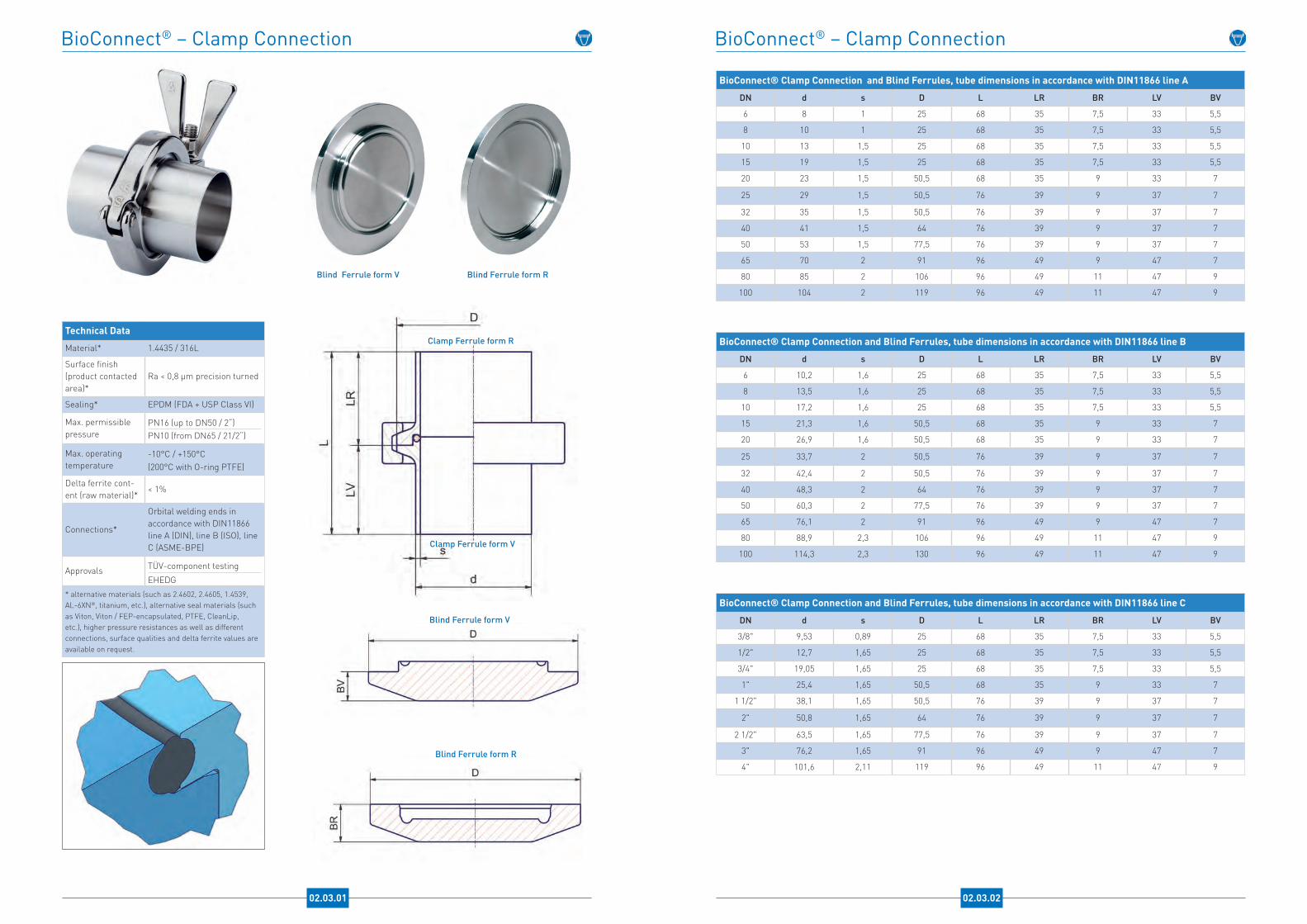
BioConnect® – Clamp Connection
Technical Data
Material* 1.4435 / 316L
Surface finish (product contacted area)*
Ra < 0,8 µm precision turned
Sealing* EPDM (FDA + USP Class VI)
Max. permissiblepressure
PN16 (up to DN50 / 2“)PN10 (from DN65 / 21/2“)
Max. operating temperature
-10°C / +150°C(200°C with O-ring PTFE)
Delta ferrite cont-ent (raw material)*
< 1%
Connections*
Orbital welding ends in accordance with DIN11866 line A (DIN), line B (ISO), line C (ASME-BPE)
Approvals TÜV-component testing
EHEDG* alternative materials (such as 2.4602, 2.4605, 1.4539, AL-6XN®, titanium, etc.), alternative seal materials (such as Viton, Viton / FEP-encapsulated, PTFE, CleanLip, etc.), higher pressure resistances as well as different connections, surface qualities and delta ferrite values are available on request.
02.03.01
Blind Ferrule form V
Blind Ferrule form V
Blind Ferrule form R
Blind Ferrule form R
Clamp Ferrule form V
Clamp Ferrule form R
BioConnect® – Clamp Connection
BioConnect® Clamp Connection and Blind Ferrules, tube dimensions in accordance with DIN11866 line A
DN d s D L LR BR LV BV
6 8 1 25 68 35 7,5 33 5,5
8 10 1 25 68 35 7,5 33 5,5
10 13 1,5 25 68 35 7,5 33 5,5
15 19 1,5 25 68 35 7,5 33 5,5
20 23 1,5 50,5 68 35 9 33 7
25 29 1,5 50,5 76 39 9 37 7
32 35 1,5 50,5 76 39 9 37 7
40 41 1,5 64 76 39 9 37 7
50 53 1,5 77,5 76 39 9 37 7
65 70 2 91 96 49 9 47 7
80 85 2 106 96 49 11 47 9
100 104 2 119 96 49 11 47 9
BioConnect® Clamp Connection and Blind Ferrules, tube dimensions in accordance with DIN11866 line B
DN d s D L LR BR LV BV
6 10,2 1,6 25 68 35 7,5 33 5,5
8 13,5 1,6 25 68 35 7,5 33 5,5
10 17,2 1,6 25 68 35 7,5 33 5,5
15 21,3 1,6 50,5 68 35 9 33 7
20 26,9 1,6 50,5 68 35 9 33 7
25 33,7 2 50,5 76 39 9 37 7
32 42,4 2 50,5 76 39 9 37 7
40 48,3 2 64 76 39 9 37 7
50 60,3 2 77,5 76 39 9 37 7
65 76,1 2 91 96 49 9 47 7
80 88,9 2,3 106 96 49 11 47 9
100 114,3 2,3 130 96 49 11 47 9
BioConnect® Clamp Connection and Blind Ferrules, tube dimensions in accordance with DIN11866 line C
DN d s D L LR BR LV BV
3/8" 9,53 0,89 25 68 35 7,5 33 5,5
1/2" 12,7 1,65 25 68 35 7,5 33 5,5
3/4" 19,05 1,65 25 68 35 7,5 33 5,5
1" 25,4 1,65 50,5 68 35 9 33 7
1 1/2" 38,1 1,65 50,5 76 39 9 37 7
2" 50,8 1,65 64 76 39 9 37 7
2 1/2" 63,5 1,65 77,5 76 39 9 37 7
3" 76,2 1,65 91 96 49 9 47 7
4" 101,6 2,11 119 96 49 11 47 9
02.03.02

BioConnect® – Screwed Connection
Technical Data
Material* 1.4435 / 316L
Surface finish (product contacted area)*
Ra < 0,8 µm precision turned
Sealing* EPDM (FDA + USP Class VI)
Max. permissiblepressure
PN16
Max. operating temperature
-10°C / +150°C(200°C with O-ring PTFE)
Delta ferrite cont-ent (raw material)*
< 1%
Connections*
Orbital welding ends in accordance with DIN11866 line A (DIN), line B (ISO), line C (ASME-BPE)
Approvals TÜV-component testing
EHEDG* Alternative materials (such as 2.4602, 2.4605, 1.4539, AL-6XN®, titanium, etc.), alternative seal materials (such as Viton, Viton / FEP-encapsulated, PTFE, CleanLip, etc.), higher pressure resistances as well as different connections, surface qualities and delta ferrite values are available on request.
02.04.01
Blind Part form R Blind Part form V
Blind Part form R
Blind Part form V
Liner
Male Part
BioConnect® – Screwed Connection
BioConnect® Screwed Connection, Blind Part form R and Blind Part form V, tube dimensions in accordance with DIN11866 line A
DN d s SW D B M L LR BR LV BV
6 8 1 7 6kt-SW19 13 M16 x 1,5 67 36 17 31 7
8 10 1 9 6kt-SW22 15 M18 x 1,5 67 36 17 31 7
10 13 1,5 10 6kt-SW27 19 M22 x 1,5 68 37 18 31 7
15 19 1,5 17 42 27 M30 x 1,5 68 37 19 31 7
20 23 1,5 19 48 33 M36 x 2 70 39 21 31 7
25 29 1,5 24 55 39 M42 x 2 81 44 21 37 8
32 35 1,5 30 65 49 M52 x 2 82 45 23 37 8
40 41 1,5 36 70 53 M56 x 2 83 46 24 37 8
50 53 1,5 46 82 65 M68 x 2 84 47 25 37 8
65 70 2 60 105 85 M90 x 3 112 64 32 48 9
80 85 2 70 115 95 M100 x 3 112 64 30 48 9
100 104 2 90 145 124 M130 x 4 114 66 34 48 9
BioConnect® Screwed Connection, Blind Part form R and Blind Part form V, tube dimensions in accordance with DIN11866 line B
DN d s SW D B M L LR BR LV BV
6 10,2 1,6 -6kt-SW
1915 M18 x 1,5 67 36 17 31 7
8 13,5 1,6 106kt-SW
2719 M22 x 1,5 68 37 17 31 7
10 17,2 1,6 156kt-SW
3023 M26 x 1,5 68 37 18 31 7
15 21,3 1,6 17 42 27 M30 x 1,5 68 37 19 31 7
20 26,9 1,6 24 48 33 M36 x 2 70 39 21 31 7
25 33,7 2 27 55 39 M42 x 2 81 44 21 37 8
32 42,4 2 36 65 49 M52 x 2 82 45 23 37 8
40 48,3 2 41 70 53 M56 x 2 83 46 24 37 8
50 60,3 2 50 82 65 M68 x 2 84 47 25 37 8
65 76,1 2 65 105 85 M90 x 3 112 64 32 48 9
80 88,9 2,3 75 115 95 M100 x 3 112 64 30 48 9
100 114,3 2,3 95 145 124 M130 x 4 114 66 34 48 9
BioConnect® Screwed Connection, Blind Part form R and Blind Part form V, tube dimensions in accordance with DIN11866 line C
DN d s SW D B M L LR BR LV BV
3/8" 9,53 0,89 -6kt-SW
1915 M18 x 1,5 67 36 17 31 7
1/2" 12,7 1,65 106kt-SW
2719 M22 x 1,5 68 37 17 31 7
3/4" 19,05 1,65 17 42 27 M30 x 1,5 68 37 19 31 7
1" 25,4 1,65 24 48 33 M36 x 2 70 39 21 31 7
1 1/2" 38,1 1,65 32 65 49 M52 x 2 82 45 23 37 8
2" 50,8 1,65 46 82 65 M68 x 2 84 47 25 37 8
2 1/2" 63,5 1,65 55 105 85 M90 x 3 112 64 32 48 9
3" 76,2 1,65 65 105 85 M90 x 3 112 64 32 48 9
4" 101,6 2,11 85 145 124 M130 x 4 114 66 34 48 9
02.04.02

Advantages NEUMO BioControl®
Constructive Benefits
•one technology, 2 housing types (inline- and angle housing)• block flanges for vessel installation • high flexibility due to standardised modular concept• more than 40 producers of measuring and analysis instruments offer their devices with NEUMO BioControl® connections• innovative, elastomer-free solution available (BioControl® CS) • cGMP compliant design• no dome, virtually no dead space
Technical Benefits
• standardised connections allows maximum flexibility, for sight glass installation as well as adaptation of instruments• minimum exposure of the medium to the elastomer• no dome like for example with tee-pieces for instruments or Ingold connections • optimal cleanbility (CIP / SIP)• controlled elastomer pressing• no elastomer return
Economic Benefits
• reduces maintenance costs and downtimes• can reduce several conventional interfaces • high potential in view of total cost of ownership• minimises the risks of process disturbances
NEUMO BioControl® Modular concept with almost unlimited adaptation opportunities
BioControl® BioControl® CS
03.01.01

BioControl® – Inline Housing G25 / G50 / G65
BioControl® – Inline Housing G25 BioControl® – Inline Housing G50 – G65
Elastomer-free solution also available (BioControl® CS) - please contact us!
BioControl® – Inline Housing G50 - G65
BioControl® – Inline Housing G25
03.02.01
Technical Data
Material* 1.4435 / 316L
Surface finish (product contacted area)*
Ra < 0,8 µm electropolished
Max. permissiblepressure
PN16
Max. operating temperature
-10°C / +200°C
Delta ferrite cont-ent (raw material)*
< 1%
Process connection G25, G50 and G65
Connections*
Orbital welding ends in accordance with DIN11866 line A (DIN), line B (ISO), line C (ASME-BPE)
Approvals TÜV-component testing
* Alternative material grades (such as 2.4602, 2.4605, 1.4539, AL-6XN®, titanium, etc.) as well as different connections, surface qualities and delta ferrite values are available on request.
BioControl® – Inline Housing G25 / G50 / G65BioControl® Inline Housing G25 / G50 / G65, tube dimensions in accordance with DIN11866 line A
Process Connection DN d s A D L H K MG25 4 6 1 28,1 64 130 26 50 M6G25 6 8 1 28,1 64 130 28 50 M6G25 8 10 1 28,1 64 130 30 50 M6G25 10 13 1,5 28,1 64 130 32 50 M6G25 15 19 1,5 28,1 64 130 38 50 M6G25 20 23 1,5 28,1 64 130 42 50 M6G50 25 29 1,5 47,6 90 150 60 70 M8G50 32 35 1,5 47,6 90 150 66 70 M8G50 40 41 1,5 47,6 90 150 72 70 M8G50 50 53 1,5 47,6 90 150 84 70 M8G50 65 70 2 47,6 90 170 100 70 M8G50 80 85 2 47,6 90 170 115 70 M8G50 100 104 2 47,6 90 170 134 70 M8G65 40 41 1,5 65,6 120 180 72 95 M10G65 50 53 1,5 65,6 120 180 84 95 M10G65 65 70 2 65,6 120 200 100 95 M10G65 80 85 2 65,6 120 200 115 95 M10
G65 100 104 2 65,6 120 200 134 95 M10
BioControl® Inline Housing G25 / G50 / G65, tube dimensions in accordance with DIN11866 line B
Process Connection DN d s A D L H K MG25 6 10,2 1,6 28,1 64 130 26 50 M6G25 8 13,5 1,6 28,1 64 130 32,3 50 M6G25 10 17,2 1,6 28,1 64 130 36 50 M6G25 15 21,3 1,6 28,1 64 130 40,1 50 M6G25 20 26,9 1,6 28,1 64 130 45,7 50 M6G50 25 33,7 2 47,6 90 150 63,7 70 M8G50 32 42,4 2 47,6 90 150 72,4 70 M8G50 40 48,3 2 47,6 90 150 78,3 70 M8G50 50 60,3 2 47,6 90 150 90,3 70 M8G50 65 76,1 2 47,6 90 170 106,1 70 M8G50 80 88,9 2,3 47,6 90 170 118,3 70 M8G50 100 114,3 2,3 47,6 90 170 143,7 70 M8G65 40 48,3 2 65,6 120 180 78,3 95 M10G65 50 60,3 2 65,6 120 180 90,3 95 M10G65 65 76,1 2 65,6 120 200 106,1 95 M10G65 80 88,9 2,3 65,6 120 200 118,3 95 M10
G65 100 114,3 2,3 65,6 120 200 143,7 95 M10
BioControl® Inline Housing G25 / G50 / G65, tube dimensions in accordance with DIN11866 line C
Process Connection DN d s A D L H K MG25 1/4" 6,35 0,89 28,1 64 130 26,75 50 M6G25 3/8" 9,53 0,89 28,1 64 130 29,75 50 M6G25 1/2" 12,7 1,65 28,1 64 130 31,4 50 M6G25 3/4" 19,05 1,65 28,1 64 130 37,75 50 M6G25 1" 25,4 1,65 28,1 64 130 44,1 50 M6G50 1" 25,4 1,65 47,6 90 150 56,1 70 M8G50 1 1/2" 38,1 1,65 47,6 90 150 68,8 70 M8G50 2" 50,8 1,65 47,6 90 150 81,5 70 M8G50 2 1/2" 63,5 1,65 47,6 90 170 94,2 70 M8G50 3" 76,2 1,65 47,6 90 170 106,9 70 M8G50 4" 101,6 2,11 47,6 90 170 131,38 70 M8G65 1 1/2" 38,1 1,65 65,6 120 180 68,8 95 M10G65 2" 50,8 1,65 65,6 120 180 81,5 95 M10G65 2 1/2" 63,5 1,65 65,6 120 200 94,2 95 M10G65 3" 76,2 1,65 65,6 120 200 106,9 95 M10
G65 4" 101,6 2,11 65,6 120 200 131,38 95 M10
03.02.02

BioControl® – Angle Housing U25 / U50 / U65
BioControl® – Angle Housing U25 BioControl® – Angle Housing U50 –
BioControl® – Angle Housing U50 – U65
BioControl® – Angle Housing U25
03.03.01
Technical Data
Material* 1.4435 / 316L
Surface finish (product contacted area)*
Ra < 0,8 µm electropolished
Max. permissiblepressure
PN16
Max.operating temperature
-10°C / +200°C
Delta ferrite cont-ent (raw material)*
< 1%
Process connection U25, U50 and U65
Connections*
Orbital welding ends in accordance with DIN11866 line A (DIN), line B (ISO), line C (ASME-BPE)
Approvals TÜV-component testing
* Alternative material grades (such as 2.4602, 2.4605, 1.4539, AL-6XN®, titanium, etc.) as well as different connections, surface qualities and delta ferrite values are available on request.
BioControl® – Angle Housing U25 / U50 / U65BioControl® – Angle Housing U25 / U50 / U65, tube dimensions in accordance with DIN11866 line A
Process Connection
DN d s A D L H h K M
U25 4 6 1 28,1 64 65 46 33 50 M6U25 6 8 1 28,1 64 65 48 34 50 M6U25 8 10 1 28,1 64 65 50 35 50 M6U25 10 13 1,5 28,1 64 65 51 35 50 M6U25 15 19 1,5 28,1 64 65 60 41 50 M6U25 20 23 1,5 28,1 64 65 65 44 50 M6U50 25 29 1,5 47,6 90 75 90 60 70 M8U50 32 35 1,5 47,6 90 75 95 62 70 M8U50 40 41 1,5 47,6 90 75 95 59 70 M8U50 50 53 1,5 47,6 90 75 105 63 70 M8U50 65 70 2 47,6 90 85 130 80 70 M8U50 80 85 2 47,6 90 90 145 87,5 70 M8U50 100 104 2 47,6 90 100 165 98 70 M8U65 40 41 1,5 65,6 120 90 105 69 95 M10U65 50 53 1,5 65,6 120 90 112 70 95 M10U65 65 70 2 65,6 120 100 130 80 95 M10U65 80 85 2 65,6 120 100 145 87,5 95 M10
U65 100 104 2 65,6 120 100 165 98 95 M10
BioControl® – Angle Housing U25 / U50 / U65, tube dimensions in accordance with DIN11866 line B
Process Connection
DN d s A D L H h K M
U25 6 10,2 1,6 28,1 64 65 48 33,5 50 M6U25 8 13,5 1,6 28,1 64 65 53 36,85 50 M6U25 10 17,2 1,6 28,1 64 65 57 39 50 M6U25 15 21,3 1,6 28,1 64 65 61 40,95 50 M6U25 20 26,9 1,6 28,1 64 65 66 43,15 50 M6U50 25 33,7 2 47,6 90 75 95 63,15 70 M8U50 32 42,4 2 47,6 90 75 95 58,8 70 M8U50 40 48,3 2 47,6 90 75 100 60,85 70 M8U50 50 60,3 2 47,6 90 75 110 64,85 70 M8U50 65 76,1 2 47,6 90 85 135 81,95 70 M8U50 80 88,9 2,3 47,6 90 90 150 90,85 70 M8U50 100 114,3 2,3 47,6 90 100 175 103,15 70 M8U65 40 48,3 2 65,6 120 90 107 67,85 95 M10U65 50 60,3 2 65,6 120 90 115 69,85 95 M10U65 65 76,1 2 65,6 120 100 135 81,95 95 M10U65 80 88,9 2,3 65,6 120 100 155 95,85 95 M10
U65 100 114,3 2,3 65,6 120 100 175 103,15 95 M10
BioControl® – Angle Housing U25 / U50 / U65, tube dimensions in accordance with DIN11866 line C
Process Connection
DN d s A D L H h K M
U25 1/4" 6,35 0,89 28,1 64 65 46 32,72 50 M6U25 3/8" 9,53 0,89 28,1 64 65 49 34,13 50 M6
U25 1/2" 12,7 1,65 28,1 64 65 52 36,3 50 M6
U25 3/4" 19,05 1,65 28,1 64 65 58 37,75 50 M6U25 1" 25,4 1,65 28,1 64 65 65 42,95 50 M6U50 1" 25,4 1,65 47,6 90 75 80 51,95 70 M8U50 1 1/2" 38,1 1,65 47,6 90 75 95 60,6 70 M8U50 2" 50,8 1,65 47,6 90 75 105 64,25 70 M8U50 2 1/2" 63,5 1,65 47,6 90 75 115 67,9 70 M8U50 3" 76,2 1,65 47,6 90 85 135 81,55 70 M8U50 4" 101,6 2,11 47,6 90 100 165 99,31 70 M8U65 1 1/2" 38,1 1,65 65,6 120 90 100 65,96 95 M10U65 2" 50,8 1,65 65,6 120 90 110 69,25 95 M10
03.03.02
Elastomer-free solution also available (BioControl® CS) - please contact us!

BioControl® – Block Flanges B25 / B50 / B65 / B80
BioControl® – Block Flange standard
BioControl® – Block Flange high version
Application Examples
BioControl® – Block Flange with welding neck
03.04.01
Technical Data
Material* 1.4435 / 316L
Surface finish (product contacted area)*
Ra < 0,8 µm electropolished
Max. permissiblepressure
PN16
Max. operating temperature
-10°C / +200°C
Delta ferrite content (raw material)*
< 1%
Process connection B25, B50, B65 and B80
Sealing* EPDM (FDA + USP Class VI)
Block flange stan-dard
Vessel wall thickness < 4mm
Block flange high version*
Vessel wall thickness> 4mm
Block flange with welding neck*
Vessel wall thickness up to 12mm
Approvals TÜV-component testing
NotificationPlease refer to our home-page for processing instructions
* Alternative material grades (such as 2.4602, 2.4605, 1.4539, AL-6XN®, titanium, etc.) as well as different designs (such as costumised heights, turned radii, etc.), surface qualities and delta ferrite values are available on request.
BioControl® – Block Flangestandard
BioControl® – Block Flangehigh version
BioControl® – Block Flangewith welding neck
BioControl® – Block Flanges B25 / B50 / B65 / B80
BioControl® – Block Flanges B25 / B50 / B65 / B80
Size A D H1 H2 B H3 h K MB25 28,1 64 11 25 144 11 8 50 4x M6B50 47,6 90 17 40 170 17 10 70 4x M8B65 65,6 120 17 50 200 17 10 95 4x M10
B80 85,1 140 25 65 220 25 10 115 4x M10
03.04.02
Elastomer-free solution also available BioControl® CS) - please contact us!
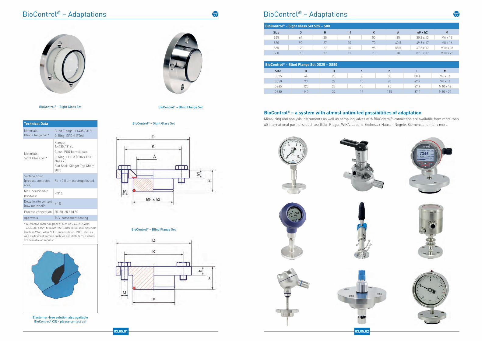
BioControl® – Sight Glass Set BioControl® – Blind Flange Set
BioControl® – Adaptations
03.05.01
BioControl® – Blind Flange Set
BioControl® – Sight Glass SetTechnical Data
Materials Blind Flange Set*
Blind Flange: 1.4435 / 316LO-Ring: EPDM (FDA)
Materials Sight Glass Set*
Flange: 1.4435 / 316L
Glass: ESG borosilicate
O-Ring: EPDM (FDA + USP class VI)Flat Seal: Klinger Top Chem 2000
Surface finish (product contacted area)
Ra < 0,8 µm electropolished
Max. permissiblepressure
PN16
Delta ferrite content (raw material)*
< 1%
Process connection 25, 50, 65 and 80
Approvals TÜV-component testing
* Alternative material grades (such as 2.4602, 2.4605, 1.4539, AL-6XN®, titanium, etc.), alternative seal materials (such as Viton, Viton / FEP-encapsulated, PTFE, etc.) as well as different surface qualities and delta ferrite values are available on request.
BioControl® – AdaptationsBioControl® – Sight Glass Set S25 – S80
Size D H h1 K A øF x h2 MS25 64 20 9 50 25 30,3 x 13 M6 x 16S50 90 27 10 70 40,5 49,8 x 17 M8 x 16S65 120 27 10 95 58,5 67,8 x 17 M10 x 18
S80 140 37 12 115 78 87,3 x 17 M10 x 25
BioControl® – Blind Flange Set DS25 – DS80
Size D H h K F MDS25 64 20 9 50 30,4 M6 x 16DS50 90 27 10 70 49,9 M8 x 16DS65 120 27 10 95 67,9 M10 x 18
DS80 140 37 12 115 87,4 M10 x 25
BioControl® – a system with almost unlimited possibilities of adaptationMeasuring and analysis instruments as well as sampling valves with BioControl®-connection are available from more than 40 international partners, such as: Gebr. Rieger, WIKA, Labom, Endress + Hauser, Negele, Siemens and many more.
03.05.02
Elastomer-free solution also available BioControl® CS) - please contact us!

Benefits of the NEUMO check valves with :
Constructive Benefits (type VC / HVC)• cGMP-compliant design and construction• excellent anti-fouling characteristics• virtually no dead space• pharmaceutical grade surface finish• uniform flow profile• optimal cleanability
Technical Benefits• no springs or membranes
• sophisticated state of the art design• ingenuously simple structure with one movable part• axial guidance of the due to housing shape
Economic Benefits• maintenance costs and downtime of pharmaceutical facilities are reduced• no need for orifice plates or expensive sensors to monitor flow rates • minimising the risks of process disturbances
NEUMO check valves and their unique shut-off element provide optimal results when being used:• to prevent reflow of condensate• in ultra-pure steam, ultra-pure water and WFI systems• to protect sensitive sterile pumps and instruments from surges in presure• in sampling systems for supplying WFI and ultra-pure water• in compressed air flushing and pressure flushing in sterile areas
Check Valves fulfil the following funda-mental technical requirements:• pressure- resp. flow- dependent on-off function• self-acting, without external actuator• outlet in one flow direction only• flow is blocked in the opposite direction• quick reaction times• reflow prevention• protects pumps and instruments from water hammer
In compliance with cGMP (Current Good Manufacturing Practice) regulations, the following requirements come along when the valves are being used in the pharmaceutical industry and sterile areas:• avoidance of contamination and cross contamination• no fouling• optimum cleaning capability• low differential pressure
cGMP Check Valves for Pharmaceutical and Aseptic Applications
04.01.01
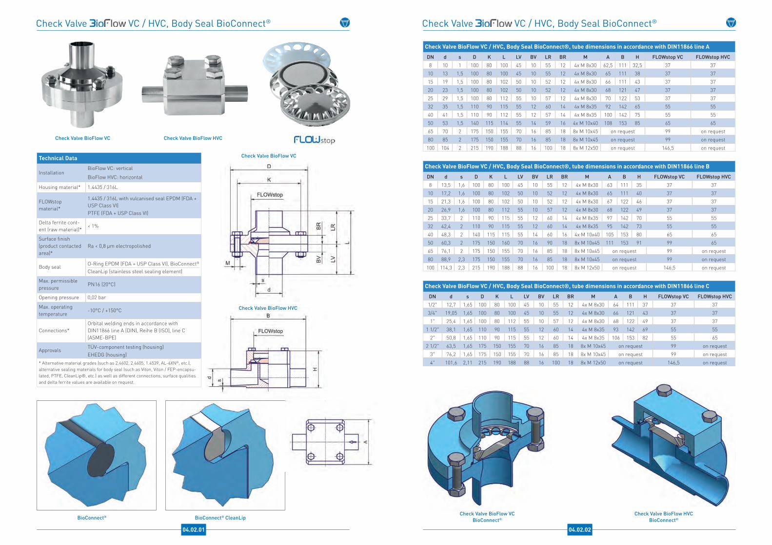
Check Valve VC / HVC, Body Seal BioConnect®
04.02.01
Technical Data
InstallationBioFlow VC: vertical
BioFlow HVC: horizontal
Housing material* 1.4435 / 316L
FLOWstop material*
1.4435 / 316L with vulcanised seal EPDM (FDA + USP Class VI)PTFE (FDA + USP Class VI)
Delta ferrite cont-ent (raw material)*
< 1%
Surface finish (product contacted area)*
Ra < 0,8 µm electropolished
Body seal O-Ring EPDM (FDA + USP Class VI), BioConnect®
CleanLip (stainless steel sealing element)
Max. permissiblepressure
PN16 (20°C)
Opening pressure 0,02 bar
Max. operating temperature
-10°C / +150°C
Connections*Orbital welding ends in accordance with DIN11866 line A (DIN), Reihe B (ISO), line C (ASME-BPE)
Approvals TÜV-component testing (housing)EHEDG (housing)
* Alternative material grades (such as 2.4602, 2.4605, 1.4539, AL-6XN®, etc.), alternative sealing materials for body seal (such as Viton, Viton / FEP-encapsu-lated, PTFE, CleanLip®, etc.) as well as different connections, surface qualities and delta ferrite values are available on request.
Check Valve BioFlow VC Check Valve BioFlow HVC
Check Valve BioFlow HVC
BioConnect® CleanLipBioConnect®
Check Valve BioFlow VC
Check Valve VC / HVC, Body Seal BioConnect®
Check Valve BioFlow VC / HVC, Body Seal BioConnect®, tube dimensions in accordance with DIN11866 line A
DN d s D K L LV BV LR BR M A B H FLOWstop VC FLOWstop HVC8 10 1 100 80 100 45 10 55 12 4x M 8x30 62,5 111 32,5 37 3710 13 1,5 100 80 100 45 10 55 12 4x M 8x30 65 111 38 37 3715 19 1,5 100 80 102 50 10 52 12 4x M 8x30 66 111 43 37 3720 23 1,5 100 80 102 50 10 52 12 4x M 8x30 68 121 47 37 3725 29 1,5 100 80 112 55 10 57 12 4x M 8x30 70 122 53 37 3732 35 1,5 110 90 115 55 12 60 14 4x M 8x35 92 142 65 55 5540 41 1,5 110 90 112 55 12 57 14 4x M 8x35 100 142 75 55 5550 53 1,5 140 115 114 55 14 59 16 4x M 10x40 108 153 85 65 6565 70 2 175 150 155 70 16 85 18 8x M 10x45 on request 99 on request80 85 2 175 150 155 70 16 85 18 8x M 10x45 on request 99 on request
100 104 2 215 190 188 88 16 100 18 8x M 12x50 on request 146,5 on request
Check Valve BioFlow VC / HVC, Body Seal BioConnect®, tube dimensions in accordance with DIN11866 line B
DN d s D K L LV BV LR BR M A B H FLOWstop VC FLOWstop HVC8 13,5 1,6 100 80 100 45 10 55 12 4x M 8x30 63 111 35 37 37
10 17,2 1,6 100 80 102 50 10 52 12 4x M 8x30 65 111 40 37 3715 21,3 1,6 100 80 102 50 10 52 12 4x M 8x30 67 122 46 37 3720 26,9 1,6 100 80 112 55 10 57 12 4x M 8x30 68 122 49 37 3725 33,7 2 110 90 115 55 12 60 14 4x M 8x35 97 142 70 55 5532 42,4 2 110 90 115 55 12 60 14 4x M 8x35 95 142 73 55 5540 48,3 2 140 115 115 55 14 60 16 4x M 10x40 105 153 80 65 6550 60,3 2 175 150 160 70 16 90 18 8x M 10x45 111 153 91 99 6565 76,1 2 175 150 155 70 16 85 18 8x M 10x45 on request 99 on request80 88,9 2,3 175 150 155 70 16 85 18 8x M 10x45 on request 99 on request
100 114,3 2,3 215 190 188 88 16 100 18 8x M 12x50 on request 146,5 on request
Check Valve BioFlow VC / HVC, Body Seal BioConnect®, tube dimensions in accordance with DIN11866 line C
DN d s D K L LV BV LR BR M A B H FLOWstop VC FLOWstop HVC1/2" 12,7 1,65 100 80 100 45 10 55 12 4x M 8x30 64 111 37 37 373/4" 19,05 1,65 100 80 100 45 10 55 12 4x M 8x30 66 121 43 37 371" 25,4 1,65 100 80 112 55 10 57 12 4x M 8x30 68 122 49 37 37
1 1/2" 38,1 1,65 110 90 115 55 12 60 14 4x M 8x35 93 142 69 55 552" 50,8 1,65 110 90 115 55 12 60 14 4x M 8x35 106 153 82 55 65
2 1/2" 63,5 1,65 175 150 155 70 16 85 18 8x M 10x45 on request 99 on request3" 76,2 1,65 175 150 155 70 16 85 18 8x M 10x45 on request 99 on request
4" 101,6 2,11 215 190 188 88 16 100 18 8x M 12x50 on request 146,5 on request
04.02.02
Check Valve BioFlow HVCBioConnect®
Check Valve BioFlow VCBioConnect®

Check Valve VC / HVC, Body Seal ConnectS®
04.03.01
Technical Data
Installation BioFlow VC: verticalBioFlow HVC: horizontal
Housing material* 1.4435 / 316L
FLOWstop material*
1.4435 / 316L with vulcanised seal EPDM (FDA + USP Class VI)
PTFE (FDA + USP Class VI)1.4435/316L elastomer-free
Delta ferrite cont-ent (raw material)*
< 1%
Surface finish (product contacted area)*
Ra < 0,8 µm electropolished
Body seal* Elastomer-free, NEUMO ConnectS®
Max. permissiblepressure
with FLOWstop Ø 37 + 55 PN16 (20°C)with FLOWstop Ø 65 + 99 PN10 )20°C)
Opening pressure 0,02 bar
Max. operating temperature
-10°C / +200°C
Connections*Orbital welding ends in accordance with DIN11866 line A (DIN), line B (ISO), line C (ASME-BPE)
Approvals
TÜV-component testing (housing)
EHEDG (housing)
TA-air (housing)
* Alternative material grades (such as 1.4539, AL-6XN®, etc.), larger dimensions, different connections, surface qualities and delta ferrite values are available on request.
Check Valve BioFlow HVC
ConnectS®
Check Valve BioFlow VC
Check Valve BioFlow VC Check Valve BioFlow HVC
Check Valve VC / HVC, Body Seal ConnectS®
Check Valve BioFlow VC / HVC, Body Seal ConnectS®, tube dimensions in accordance with DIN11866 line A
DN d s D K L LV BV LR BR M A B H FLOWstop VC FLOWstop HVC8 10 1 115 85 106 52 12 54 14 4x M 14x40 73,5 122 35 37 3710 13 1,5 115 85 106 52 12 54 14 4x M 14x40 74,5 122 38,5 37 3715 19 1,5 115 85 106 52 12 54 14 4x M 14x40 76 122 44 37 3720 23 1,5 115 85 112 55 12 57 14 4x M 14x40 77 132 47,5 37 3725 29 1,5 115 85 112 55 12 57 14 4x M 14x40 79,5 132 53,5 37 3732 35 1,5 125 95 115 55 12 60 14 4x M 14x40 103 155 64,5 55 5540 41 1,5 125 95 115 55 12 60 14 4x M 14x40 105,5 155 70,5 55 55
50 53 1,5 145 115 125 60 14 65 16 8x M 12x45 118 165 85,5 65 65
Check Valve BioFlow VC / HVC, Body Seal ConnectS®, tube dimensions in accordance with DIN11866 line B
DN d s D K L LV BV LR BR M A B H FLOWstop VC FLOWstop HVC8 13,5 1,6 115 85 106 52 12 54 14 4x M 14x40 74,5 122 38,5 37 3710 17,2 1,6 115 85 106 52 12 54 14 4x M 14x40 75,5 130 42 37 3715 21,3 1,6 115 85 106 52 12 54 14 4x M 14x40 76,5 140 45,5 37 3720 26,9 1,6 115 85 106 52 12 54 14 4x M 14x40 78,5 140 51 37 3725 33,7 2 125 95 115 55 12 60 14 4x M 14x40 102,5 155 63 55 5532 42,4 2 125 95 115 55 12 60 14 4x M 14x40 106 155 72 55 5540 48,3 2 145 115 115 55 14 60 16 8x M 12x45 115,5 165 81 65 65
50 60,3 2 180 150 160 70 16 90 18 8x M 12x50 122 165 93 99 65
Check Valve BioFlow VC / HVC, Body Seal ConnectS®, tube dimensions in accordance with DIN11866 line C
DN d s D K L LV BV LR BR M A B H FLOWstop VC FLOWstop HVC1/2" 12,7 1,65 115 85 106 52 12 54 14 4x M 14x40 74 122 37 37 373/4" 19,05 1,65 115 85 106 52 12 54 14 4x M 14x40 75,5 132 43 37 371" 25,4 1,65 115 85 112 55 12 57 14 4x M 14x40 78 132 50 37 37
1 1/2" 38,1 1,65 125 95 115 55 12 60 14 4x M 14x40 104 155 67,5 55 55
2" 50,8 1,65 145 115 125 60 14 65 16 8x M 12x45 117 165 83,5 65 65
04.03.02
Check Valve BioFlow HVCConnectS®
Check Valve BioFlow VCConnectS®

Check Valve TCVC, Body Seal Tri-Clamp
04.04.01
Technical Data
Installation Vertical
Housing material* 1.4435 / 316L
FLOWstop material*
1.4435 / 316L with vulcanised seal EPDM (FDA + USP Class VI)PTFE (FDA + USP Class VI)
Delta ferrite cont-ent (raw material)*
< 1%
Surface finish (product contacted area)*
Ra < 0,8 µm precision turned
Body seal*Clamp seal EPDM (FDA + USP Class VI), DIN32676 / ASME-BPE
Max. permissiblepressure
PN10 (20°C)
Opening pressure 0,02 bar
Max. operating temperature
-10°C / +150°C (up to 200°C if PTFE is used for FLOWstop and housing seal)
Connections*Orbital welding ends in accordance with DIN11866 line A (DIN), line B (ISO), line C (ASME-BPE)
* Alternative material grades (such as 2.4602, 2.4605, 1.4539, AL-6XN®, titanium etc.), alternative sealing materials such as Viton, Viton / FEP-encapsulated, PTFE, etc.) as well as different connec-tions, surface qualities and delta ferrite values are available on request.
Check Valve BioFlow TCVC
Check Valve BioFlow TCVC
Check Valve TCVC, Body Seal Tri-Clamp
Check Valve BioFlow TCVC, tube dimensions in accordance with DIN11866 line A
DN d s D ca . L L1 L2 FLOWstop8 10 1 50,5 65 25 38 37
10 13 1,5 50,5 65 25 38 3715 19 1,5 50,5 65 25 38 3720 23 1,5 50,5 65 25 38 3725 29 1,5 50,5 65 25 38 3732 35 1,5 50,5 65 25 38 3740 41 1,5 77,5 75 30 43 55
50 53 1,5 91 75 30 43 65
Check Valve BioFlow TCVC, tube dimensions in accordance with DIN11866 line B
DN d s D ca . L L1 L2 FLOWstop8 13,5 1,6 50,5 65 25 38 37
10 17,2 1,6 50,5 65 25 38 3715 21,3 1,6 50,5 65 25 38 3720 26,9 1,6 50,5 65 25 38 3725 33,7 2 50,5 65 25 38 3732 42,4 2 77,5 75 30 43 5540 48,3 2 77,5 75 30 43 55
50 60,3 2 130 112 45 65 99
Check Valve BioFlow TCVC, tube dimensions in accordance with DIN11866 line C
DN d s D ca . L L1 L2 FLOWstop1/2" 12,7 1,65 50,5 65 25 38 373/4" 19,05 1,65 50,5 65 25 38 371" 25,4 1,65 50,5 65 25 38 37
1 1/2" 38,1 1,65 77,5 75 30 43 55
2" 50,8 1,65 77,5 75 30 43 55
04.04.02
Check Valve BioFlow TCVC
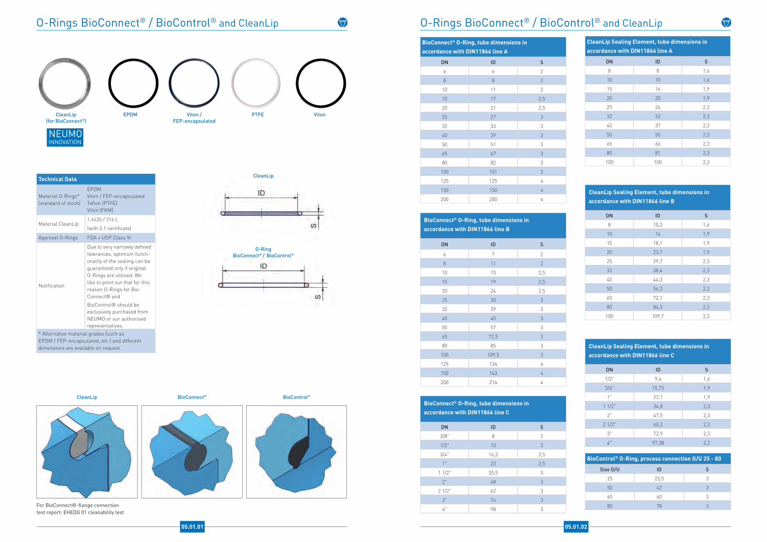
Technical Data
Material O-Rings*(standard of stock)
EPDMViton / FEP-encapsulatedTeflon (PTFE)Viton (FKM)
Material CleanLip1.4435 / 316 L
(with 3.1 certificate)
Approval O-Rings FDA + USP Class VI
Notification
Due to very narrowly defined tolerances, optimum functi-onality of the sealing can be guaranteed only if original O-Rings are utilised. We like to point out that for this reason O-Rings for Bio-Connect® and
BioControl® should be exclusively purchased from NEUMO or our authorised representatives.
* Alternative material grades (such as EPDM / FEP-encapsulated, etc.) and different dimensions are available on request.
CleanLip(for BioConnect®)
EPDM Viton /FEP-encapsulated
PTFE Viton
CleanLip
For BioConnect®-flange connectiontest report: EHEDG 01 cleanability test
BioConnect® BioControl®
CleanLip
O-RingBioConnect® / BioControl®
O-Rings BioConnect® / BioControl® and CleanLip O-Rings BioConnect® / BioControl® and CleanLip
BioControl® O-Ring, process connection G/U 25 - 80
Size G/U ID S
25 23,5 3
50 42 3
65 60 3
80 78 3
BioConnect® O-Ring, tube dimensions in accordance with DIN11866 line A
DN ID S
6 6 2
8 8 2
10 11 2
15 17 2,5
20 21 2,5
25 27 3
32 33 3
40 39 3
50 51 3
65 67 3
80 82 3
100 101 3
125 125 4
150 150 4
200 200 4
BioConnect® O-Ring, tube dimensions in accordance with DIN11866 line B
DN ID S
6 7 2
8 11 2
10 15 2,5
15 19 2,5
20 24 2,5
25 30 3
32 39 3
40 45 3
50 57 3
65 72,5 3
80 85 3
100 109,5 3
125 134 4
150 163 4
200 214 4
BioConnect® O-Ring, tube dimensions in accordance with DIN11866 line C
DN ID S
3/8" 8 2
1/2" 10 2
3/4" 16,3 2,5
1" 23 2,5
1 1/2" 35,5 3
2" 48 3
2 1/2" 62 3
3" 74 3
4" 98 3
CleanLip Sealing Element, tube dimensions in accordance with DIN11866 line A
DN ID S
8 8 1,6
10 10 1,6
15 16 1,9
20 20 1,9
25 26 2,3
32 32 2,3
40 37 2,3
50 50 2,3
65 66 2,3
80 81 2,3
100 100 2,3
CleanLip Sealing Element, tube dimensions in accordance with DIN11866 line B
DN ID S
8 10,3 1,6
10 14 1,9
15 18,1 1,9
20 23,7 1,9
25 29,7 2,3
32 38,4 2,3
40 44,3 2,3
50 56,3 2,3
65 72,1 2,3
80 84,3 2,3
100 109,7 2,3
CleanLip Sealing Element, tube dimensions in accordance with DIN11866 line C
DN ID S
1/2" 9,4 1,6
3/4" 15,75 1,9
1" 22,1 1,9
1 1/2" 34,8 2,3
2" 47,5 2,3
2 1/2" 60,2 2,3
3" 72,9 2,3
4" 97,38 2,3
NEUMOINNOVATION
05.01.02 05.01.01
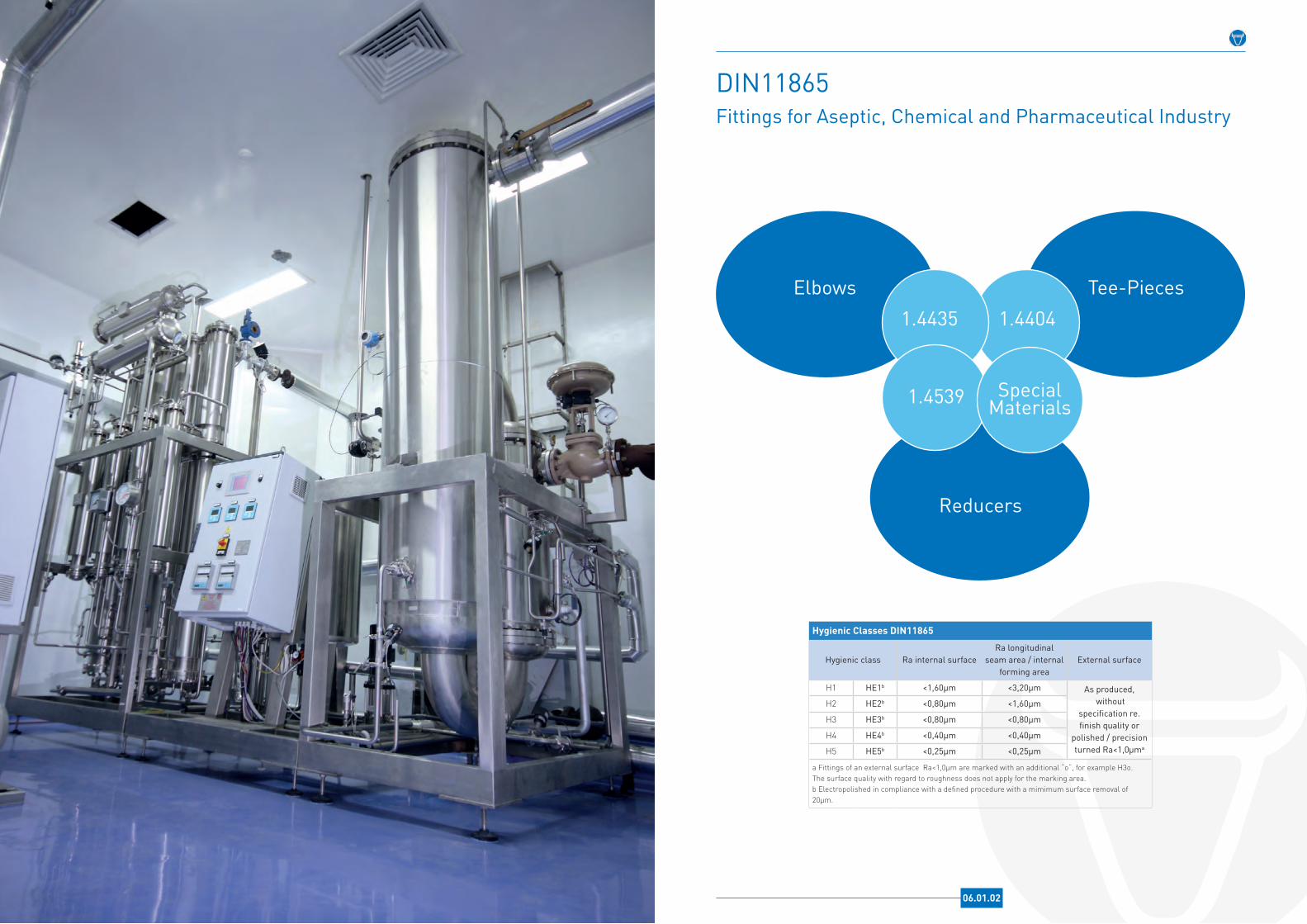
DIN11865Fittings for Aseptic, Chemical and Pharmaceutical Industry
Reducers
Elbows Tee-Pieces1 .4435 1 .4404
1 .4539
Hygienic Classes DIN11865
Hygienic class Ra internal surfaceRa longitudinal
seam area / internal forming area
External surface
H1 HE1b <1,60µm <3,20µm As produced, without
specification re . finish quality or
polished / precision turned Ra<1,0µma
H2 HE2b <0,80µm <1,60µm
H3 HE3b <0,80µm <0,80µm
H4 HE4b <0,40µm <0,40µm
H5 HE5b <0,25µm <0,25µm
a Fittings of an external surface Ra<1,0µm are marked with an additional “o“, for example H3o. The surface quality with regard to roughness does not apply for the marking area.b Electropolished in compliance with a defined procedure with a mimimum surface removal of 20µm.
06.01.02

Elbow DIN11865, Form BL-90 and BL-45
06.02.01
Technical Data
Material* 1.4435
NormDIN11865
(actual version)
Design BL
Surface finish(standard of stock)*
H3o
HE3
H4oHE4
DF-class* 3 (<0,5%)
Connections*
Orbital welding ends in ac-cordance with DIN11865 line A (DIN), line B (ISO), line C (ASME-BPE)
* Alternative material grades (such as 1.4539, 2.4602, 2.4605, etc.), different surface qualities and connections as well as customised elbows (88°, 92°, 30°, 60°, etc.), also with special radii, are available on request.
Elbow 45°, form BL Elbow 90°, form BL
Elbow DIN11865, form BL-45
Elbow DIN11865, form BL-90
Elbow DIN11865, Form BL-90 and BL-45
Elbow DIN11865, form BL-90 and BL-45, tube dimensions in accordance with DIN11866 line A
DN d s R l1 l2 l3
6 8 1 20 45 33,3 25
8 10 1 25 50 35,4 25
10 13 1,5 26 51 35,8 25
15 19 1,5 35 60 39,5 25
20 23 1,5 40 65 41,6 25
25 29 1,5 50 90 60,7 40
32 35 1,5 55 95 62,8 40
40 41 1,5 60 100 64,9 40
50 53 1,5 70 110 69,0 40
65 70 2 80 120 73,1 40
80 85 2 90 145 92,3 55
100 104 2 100 155 96,4 55
125 129 2 187,5 270 160,2 82,5
150 154 2 225 325 193,2 100
200 204 2 300 400 224,3 100
Elbow DIN11865, form BL-90 and BL-45, tube dimensions in accordance with DIN11866 line B
DN d s R l1 l2 l3
6 10,2 1,6 20 45 33,3 25
8 13,5 1,6 20 45 33,3 25
10 17,2 1,6 28 53 36,6 25
15 21,3 1,6 30 55 37,4 25
20 26,9 1,6 28,5 68,5 51,8 40
25 33,7 2 38 78 55,7 40
32 42,4 2 47,5 87,5 59,7 40
40 48,3 2 57 97 63,6 40
50 60,3 2 76 116 71,5 40
65 76,1 2 95 150 94,4 55
80 88,9 2,3 114,5 169,5 102,4 55
100 114,3 2,3 152,5 207,5 118,2 55
125 139,7 2,6 190,5 245,5 133,9 55
150 168,3 2,6 228,5 283,5 149,7 55
200 219,1 2,6 305 385 206,3 80
Elbow DIN11865, form BL-90 and BL-45, tube dimensions in accordance with DIN11866 line C
DN d s R l1 l2 l3 / 90° l3 / 45°
1/4" 6,35 0,89 14,3 66,7 50,8 52,4 44,9
3/8" 9,53 0,89 28,6 66,7 50,8 38,1 39
1/2" 12,7 1,65 28,6 76,2 57,2 47,6 45,4
3/4" 19,05 1,65 28,6 76,2 57,2 47,6 45,4
1" 25,4 1,65 38,1 76,2 57,2 38,1 41,4
1 1/2" 38,1 1,65 57,2 95,3 63,5 38,1 39,8
2" 50,8 1,65 76,2 120,7 76,2 44,5 44,6
2 1/2" 63,5 1,65 95,3 139,7 85,7 44,4 46,2
3" 76,2 1,65 114,3 158,8 92,1 44,5 44,8
4" 101,6 2,11 152,4 203,2 114,3 50,8 51,2
6" 152,4 2,77 228,6 292,1 158,8 63,5 64,1
06.02.02
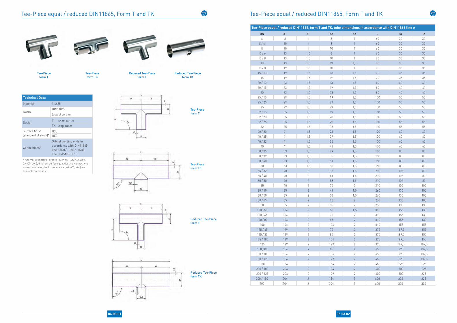
Tee-Piece equal / reduced DIN11865, Form T and TK
Technical Data
Material* 1.4435
NormDIN11865
(actual version)
Design T short outlet
TK long outlet
Surface finish(standard of stock)*
H3oHE3
Connections*
Orbital welding ends in accordance with DIN11865 line A (DIN), line B (ISO), line C (ASME-BPE)
* Alternative material grades (such as 1.4539, 2.4602, 2.4605, etc.), different surface qualities and connections as well as customised components (exit 45°, etc.) are available on request.
Reduced Tee-Pieceform TK
Reduced Tee-Pieceform T
Tee-Pieceform TK
Tee-Pieceform T
Tee-Pieceform T
Tee-Pieceform TK
Reduced Tee-Pieceform T
Reduced Tee-Pieceform TK
06.03.01
Tee-Piece equal / reduced DIN11865, Form T and TK
Tee-Piece equal / reduced DIN11865, form T and TK, tube dimensions in accordance with DIN11866 line A
DN d1 s1 d2 s2 L lo l26 8 1 8 1 60 30 30
8 / 6 10 1 8 1 60 30 308 10 1 10 1 60 30 30
10 / 6 13 1,5 8 1 60 30 3010 / 8 13 1,5 10 1 60 30 30
10 13 1,5 13 1,5 70 35 3515 / 8 19 1,5 10 1 70 35 3515 / 10 19 1,5 13 1,5 70 35 35
15 19 1,5 19 1,5 70 35 3520 / 10 23 1,5 13 1,5 80 40 4020 / 15 23 1,5 19 1,5 80 40 40
20 23 1,5 23 1,5 80 40 4025 / 15 29 1,5 19 1,5 100 50 5025 / 20 29 1,5 23 1,5 100 50 50
25 29 1,5 29 1,5 100 50 5032 / 15 35 1,5 19 1,5 110 55 5532 / 20 35 1,5 23 1,5 110 55 5532 / 25 35 1,5 29 1,5 110 55 55
32 35 1,5 35 1,5 110 55 5540 / 20 41 1,5 23 1,5 120 60 6040 / 25 41 1,5 29 1,5 120 60 6040 / 32 41 1,5 35 1,5 120 60 60
40 41 1,5 41 1,5 120 60 6050 / 25 53 1,5 29 1,5 160 80 8050 / 32 53 1,5 35 1,5 160 80 8050 / 40 53 1,5 41 1,5 160 80 80
50 53 1,5 53 1,5 160 80 8065 / 32 70 2 35 1,5 210 105 8065 / 40 70 2 41 1,5 210 105 8060 / 50 70 2 53 1,5 210 105 80
65 70 2 70 2 210 105 10580 / 40 85 2 41 1,5 260 130 10580 / 50 85 2 53 1,5 260 130 10580 / 65 85 2 70 2 260 130 105
80 85 2 85 2 260 130 130100 / 50 104 2 53 1,5 310 155 130100 / 65 104 2 70 2 310 155 130100 / 80 104 2 85 2 310 155 130
100 104 2 104 2 310 155 155125 / 65 129 2 70 2 375 187,5 155125 / 80 129 2 85 2 375 187,5 155125 / 100 129 2 104 2 375 187,5 155
125 129 2 129 2 375 187,5 187,5150 / 80 154 2 85 2 450 225 187,5150 / 100 154 2 104 2 450 225 187,5150 / 125 154 2 129 2 450 225 187,5
150 154 2 154 2 450 225 225200 / 100 204 2 104 2 600 300 225200 / 125 204 2 129 2 600 300 225200 / 150 204 2 154 2 600 300 225
200 204 2 204 2 600 300 300
06.03.02

Tee-Piece equal / reduced DIN11865, form T and TK, tube dimensions in accordance with DIN11866 line B
DN d1 s1 d2 s2 L lo l26 10,2 1,6 10,2 1,6 60 30 30
8 / 6 13,5 1,6 10,2 1,6 64 32 328 13,5 1,6 13,5 1,6 64 32 32
10 / 6 17,2 1,6 10,2 1,6 68 34 3410 / 8 17,2 1,6 13,5 1,6 68 34 34
10 17,2 1,6 17,2 1,6 68 34 3415 / 6 21,3 1,6 10,2 1,6 72 36 3615 / 8 21,3 1,6 13,5 1,6 72 36 36
15 / 10 21,3 1,6 17,2 1,6 72 36 3615 21,3 1,6 21,3 1,6 72 36 36
20 / 8 26,9 1,6 13,5 1,6 110 55 5520 / 10 26,9 1,6 17,2 1,6 110 55 5520 / 15 26,9 1,6 21,3 1,6 110 55 55
20 26,9 1,6 26,9 1,6 110 55 5525 / 10 33,7 2 17,2 1,6 120 60 6025 / 15 33,7 2 21,3 1,6 120 60 6025 / 20 33,7 2 26,9 1,6 120 60 60
25 33,7 2 33,7 2 120 60 6032 / 15 42,4 2 21,3 1,6 130 65 6532 / 20 42,4 2 26,9 1,6 130 65 6532 / 25 42,4 2 33,7 2 130 65 65
32 42,4 2 42,4 2 130 65 6540 / 20 48,3 2 26,9 1,6 130 65 6540 / 25 48,3 2 33,7 2 130 65 6540 / 32 48,3 2 42,4 2 130 65 65
40 48,3 2 48,3 2 130 65 6550 / 25 60,3 2 33,7 2 180 90 9050 / 32 60,3 2 42,4 2 180 90 9050 / 40 60,3 2 48,3 2 180 90 90
50 60,3 2 60,3 2 180 90 9065 / 32 76,1 2 42,4 2 220 110 9065 / 40 76,1 2 48,3 2 220 110 9065 / 50 76,1 2 60,3 2 220 110 90
65 76,1 2 76,1 2 220 110 11080 / 40 88,9 2,3 48,3 2 260 130 11080 / 50 88,9 2,3 60,3 2 260 130 11080 / 65 88,9 2,3 76,1 2 260 130 110
80 88,9 2,3 88,9 2,3 260 130 130100 / 50 114,3 2,3 60,3 2 320 160 130100 / 65 114,3 2,3 76,1 2 320 160 130100 / 80 114,3 2,3 88,9 2,3 320 160 130
100 114,3 2,3 114,3 2,3 320 160 160125 / 65 139,7 2,6 76,1 2 400 200 160125 / 80 139,7 2,6 88,9 2,3 400 200 160
125 / 100 139,7 2,6 114,3 2,3 400 200 160125 139,7 2,6 139,7 2,6 400 200 200
150 / 80 168,3 2,6 88,9 2,3 500 250 200150 / 100 168,3 2,6 114,3 2,3 500 250 200150 / 125 168,3 2,6 139,7 2,6 500 250 200
150 168,3 2,6 168,3 2,6 500 250 250200 / 100 219,1 2,6 114,3 2,3 600 300 250200 / 125 219,1 2,6 139,7 2,6 600 300 250200 / 150 219,1 2,6 168,3 2,6 600 300 250
200 219,1 2,6 219,1 2,6 600 300 300
Tee-Piece equal / reduced DIN11865, Form T and TK
06.03.03
Tee-Piece equal / reduced DIN11865, Form T and TK
Tee-Piece equal / reduced DIN11865, form T and TK, tube dimensions in accordance with DIN11866 line C
DN d1 s1 d2 s2 L lo l2
1/4" 6,35 0,89 6,35 0,89 89 44,5 44,53/8" / 1/4" 9,53 0,89 6,35 0,89 89 44,5 44,5
3/8" 9,53 0,89 9,53 0,89 89 44,5 44,51/2" / 1/4" 12,7 1,65 6,35 0,89 95,2 47,6 47,61/2" / 3/8" 12,7 1,65 9,53 0,89 95,2 47,6 47,6
1/2" 12,7 1,65 12,7 1,65 95,2 47,6 47,63/4" / 3/8" 19,05 1,65 9,53 0,89 101,6 50,8 50,83/4" / 1/2" 19,05 1,65 12,7 1,65 101,6 50,8 50,8
3/4" 19,05 1,65 19,05 1,65 101,6 50,8 50,81" /1/2" 25,4 1,65 12,7 1,65 108 54 541" / 3/4" 25,4 1,65 19,05 1,65 108 54 54
1" 25,4 1,65 25,4 1,65 108 54 541 1/2" / 3/4" 38,1 1,65 19,05 1,65 120,6 60,3 60,31 1/2" / 1" 38,1 1,65 25,4 1,65 120,6 60,3 60,3
1 1/2" 38,1 1,65 38,1 1,65 120,6 60,3 60,32" / 1" 50,8 1,65 25,4 1,65 146 73 66,7
2" / 1 1/2" 50,8 1,65 38,1 1,65 146 73 66,72" 50,8 1,65 50,8 1,65 146 73 73
2 1/2" / 1 1/2" 63,5 1,65 38,1 1,65 158,8 79,4 732 1/2" / 2" 63,5 1,65 50,8 1,65 158,8 79,4 73
2 1/2" 63,5 1,65 63,5 1,65 158,8 79,4 79,43" / 1 1/2" 76,2 1,65 38,1 1,65 171,4 85,7 79,4
3" / 2" 76,2 1,65 50,8 1,65 171,4 85,7 79,43" / 2 1/2" 76,2 1,65 63,5 1,65 171,4 85,7 79,4
3" 76,2 1,65 76,2 1,65 171,4 85,7 85,74" / 2" 101,6 2,11 50,8 1,65 209,6 104,8 98,4
4" / 2 1/2" 101,6 2,11 63,5 1,65 209,6 104,8 98,44" / 3" 101,6 2,11 76,2 1,65 209,6 104,8 98,4
4" 101,6 2,11 101,6 2,11 209,6 104,8 104,86" / 3" 152,4 2,77 76,2 1,65 185,8 142,9 123,86" / 4" 152,4 2,77 101,6 2,11 185,8 142,9 130,2
6" 152,4 2,77 152,4 2,77 185,8 142,9 142,9
06.03.04

Reducer concentric form RK
Reducers DIN11865, Form RK and RE
Reducer eccentricform RE
Reducer eccentricform RE
Reducer concentricform RKTechnical Data
Material* 1.4435
NormDIN11865
(actual version)
Design RK concentricRE eccentric
Surface finish(standard of stock)*
H3
DF-class* DF3 (<0,5%)
Connections*
Orbital welding ends in accordance with DIN11865 line A (DIN), line B (ISO), line C (ASME-BPE)
* Alternative material grades (such as 1.4539, 2.4602, 2.4605, etc.), different surface qualities and connections as well as customised components (adaptors etc.) are available on request.
06.04.01
Reducers DIN11865, Form RK and RE
Reducers DIN11865, form RK and RE, tube dimensions in accordance with DIN11866 line A
DN d1 s1 d2 s2 L l1 l28 / 6 10 1 8 1 38 19 1910 / 6 13 1,5 8 1 38 19 1910 / 8 13 1,5 10 1 38 19 1915 / 8 19 1,5 10 1 60 25 2515 / 10 19 1,5 13 1,5 60 25 2520 / 10 23 1,5 13 1,5 60 25 2520 / 15 23 1,5 19 1,5 60 25 2525 / 15 29 1,5 19 1,5 70 25 2525 / 20 29 1,5 23 1,5 70 25 2532 / 20 35 1,5 23 1,5 80 30 2532 / 25 35 1,5 29 1,5 80 30 2540 / 20 41 1,5 23 1,5 90 30 2540 / 25 41 1,5 29 1,5 90 30 2540 / 32 41 1,5 35 1,5 90 30 3050 / 25 53 1,5 29 1,5 90 30 2550 / 32 53 1,5 35 1,5 90 30 3050 / 40 53 1,5 41 1,5 90 30 3065 / 40 70 2 41 1,5 110 40 3065 / 50 70 2 53 1,5 110 40 3080 / 50 85 2 53 1,5 110 40 3080 / 65 85 2 70 2 110 40 40100 / 65 104 2 70 2 135 40 40100 / 80 104 2 85 2 135 40 40125 / 80 129 2 85 2 150 55 40125 / 100 129 2 104 2 150 55 40150 / 100 154 2 104 2 170 55 40150 / 125 154 2 129 2 170 55 55200 / 125 204 2 129 2 230 55 55
200 / 150 204 2 154 2 230 55 55
06.04.02
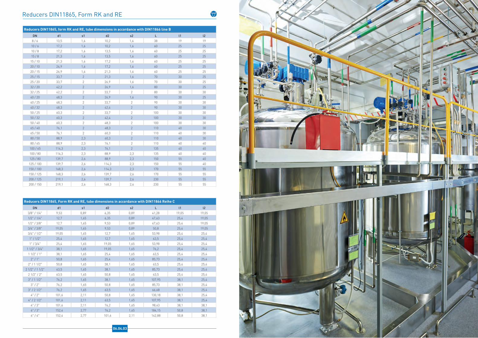
Reducers DIN11865, form RK and RE, tube dimensions in accordance with DIN11866 line B
DN d1 s1 d2 s2 L l1 l28 / 6 13,5 1,6 10,2 1,6 38 19 19
10 / 6 17,2 1,6 10,2 1,6 60 25 2510 / 8 17,2 1,6 13,5 1,6 60 25 2515 / 8 21,3 1,6 13,5 1,6 60 25 25
15 / 10 21,3 1,6 17,2 1,6 60 25 2520 / 10 26,9 1,6 17,2 1,6 60 25 2520 / 15 26,9 1,6 21,3 1,6 60 25 2525 / 15 33,7 2 21,3 1,6 70 30 2525 / 20 33,7 2 26,9 1,6 70 30 2532 / 20 42,2 2 26,9 1,6 80 30 2532 / 25 42,2 2 33,7 2 80 30 3040 / 20 48,3 2 26,9 1,6 90 30 2540 / 25 48,3 2 33,7 2 90 30 3040 / 32 48,3 2 42,4 2 90 30 3050 / 25 60,3 2 33,7 2 100 30 3050 / 32 60,3 2 42,4 2 100 30 3050 / 40 60,3 2 48,3 2 100 30 3065 / 40 76,1 2 48,3 2 110 40 3065 / 50 76,1 2 60,3 2 110 40 3080 / 50 88,9 2,3 60,3 2 110 40 3080 / 65 88,9 2,3 76,1 2 110 40 40
100 / 65 114,3 2,3 76,1 2 135 40 40100 / 80 114,3 2,3 88,9 2,3 135 40 40125 / 80 139,7 2,6 88,9 2,3 150 55 40
125 / 100 139,7 2,6 114,3 2,3 150 55 40150 / 100 168,3 2,6 114,3 2,3 170 55 55150 / 125 168,3 2,6 139,7 2,6 170 55 55200 / 125 219,1 2,6 139,7 2,6 230 55 55
200 / 150 219,1 2,6 168,3 2,6 230 55 55
Reducers DIN11865, Form RK and RE, tube dimensions in accordance with DIN11866 Reihe C
DN d1 s1 d2 s2 L l1 l23/8" / 1/4" 9,53 0,89 6,35 0,89 41,28 19,05 19,051/2" / 1/4" 12,7 1,65 6,35 0,89 47,63 25,4 19,051/2" / 3/8" 12,7 1,65 9,53 0,89 47,63 25,4 19,053/4" / 3/8" 19,05 1,65 9,53 0,89 50,8 25,4 19,053/4" / 1/2" 19,05 1,65 12,7 1,65 53,98 25,4 25,41" / 1/2" 25,4 1,65 12,7 1,65 63,5 25,4 25,41" / 3/4" 25,4 1,65 19,05 1,65 53,98 25,4 25,4
1 1/2" / 3/4" 38,1 1,65 19,05 1,65 76,2 25,4 25,41 1/2" / 1" 38,1 1,65 25,4 1,65 63,5 25,4 25,4
2" / 1" 50,8 1,65 25,4 1,65 85,73 25,4 25,42" / 1 1/2" 50,8 1,65 38,1 1,65 63,5 25,4 25,4
2 1/2" / 1 1/2" 63,5 1,65 38,1 1,65 85,73 25,4 25,42 1/2" / 2" 63,5 1,65 50,8 1,65 63,5 25,4 25,43" / 1 1/2" 76,2 1,65 38,1 1,65 107,95 38,1 25,4
3" / 2" 76,2 1,65 50,8 1,65 85,73 38,1 25,43" / 2 1/2" 76,2 1,65 63,5 1,65 66,68 38,1 25,4
4" / 2" 101,6 2,11 50,8 1,65 130,18 38,1 25,44" / 2 1/2" 101,6 2,11 63,5 1,65 107,95 38,1 25,4
4" / 3" 101,6 2,11 76,2 1,65 98,43 38,1 38,16" / 3" 152,4 2,77 76,2 1,65 184,15 50,8 38,1
6" / 4" 152,4 2,77 101,6 2,11 142,88 50,8 38,1
Reducers DIN11865, Form RK and RE
06.04.03

For many years, our engineers and technicians have been playing an active role in all important German, European and Amercian standardisation committees, such as DIN or ASME-BPE. Therefore, NEUMO is centrally involved in the standardisation of pharmaceutical tubing.
NEUMO‘s activities are focussing on tubing for Pharmaceutical, Chemical and Biotechnologi-cal use as well as for other critical applica-tions. Today, NEUMO keeps one of the largest and most wide-ranging warehouses throug-hout the world. Furthermore, an optimum availability is guaranteed by means of many additional warehouses throughout Europe, Switzerland, China, Vietnam, Israel and the U.S, including customised designs and special materials. We cooperate with the leading tube mills throughout Europe and the U.S. producing our tubes in accordance with our specifications. They are marketed under the following brand names:
• NEUMO Pharmatube ECO
• NEUMO Pharmatube S
• NEUMO Pharmatube XS
• NEUMO Pharmatube BPE
• NEUMO PharmAlloy 1.4539
• NEUMO PharmAlloy AL-6XN®
• NEUMO Alloy C-22
Working exclusively with just a few selected, certified tube mills audited by renowned pharmaceutical enterprises enables us to safeguard the highest standards of quality assurance.
NEUMO PharmatubeStainless Steel and Special Alloy Tubes for Pharmaceutical, Chemical and Biotechnological Industry
07.01.01

NEUMO Pharmatube XSNorm: DIN11866Design: Welded (small diameters partly seamless) Material: 1.4435 / 316LHygienic classes: H4o (interior Ra<0,4µm) optional: HE4oDelta ferrite content: Max. 0,5% (DF3)External surface: Mechanical polished, seamless design bright annealed / shiny metallicRegulation: AD2000-W2
NEUMO Pharmatube SNorm: DIN11866Design: Welded (small diameters partly seamless) Material: 1.4435 / 316L 1.4404 / 316LHygienic classes: H3o (internal Ra<0,8µm) Optional: HE3oDelta ferrite content: Max. 0,5% (DF3)External surface: Mechanical polishedRegulation: AD2000-W2
NEUMO Pharmatube ECONorm: DIN11866Design: Welded (small diameters partly seamless) Material: 1.4404 / 316LHygienic classes: H2 (internal Ra<0,8µm, near welding seam: Ra<1,6µm) Optional: H2o, HE2, HE2oExternal surface: Pickled or bright annealedRegulation: AD2000-W2
NEUMO Pharmatube BPENorm: ASME-BPEDesign: Welded (1/4 “- 3/4“ also as seamless design)Material: 316LHygienic classes: SF1 (internal Ra<0,51µm mechanical polished) SF4 (internal Ra<0,38µm electropolished),External surface: Mechanical polished, seamless design pickled Optional: bright annealed / shiny metallic Regulation: ASTM A249/269/270/S2
NEUMO Pharmatube
NEUMO PharmAlloy 1.4539Norm: DIN11866 (from stock in line B, further dimensions on request)Design: Welded (small diameters mainly seamless)Material: 1.4539 / 904LHygienic classes: H3 (internal Ra<0,8µm)Optionally available: H2, H2o, H3o, HE3, HE3o, further surface classes available on requestDelta ferrite content: Max. 0,5% (DF3)External surface: Pickled or bright annealed / shiny metallic Optional: mechanical polishedRegulation: AD2000-W2
NEUMO PharmAlloy AL-6XN®*Welding ends: ASME-BPEDesign: Welded (small diameters partly seamless) Material: AL-6XN® (complies to 1.4529)Hygienic classes: Internal Ra<0,8µm Internal Ra<0,6µm electropolished, further surface classes on requestExternal surface: Pickled or bright annealed/shiny metallic Optional: mechanical polished
* AL-6XN® is a registered trademark of ATI Properties, Inc
NEUMO Alloy C-22Welding ends: ASME-BPE ANSI Schedule10, further dimensions on requestDesign: Welded (small diameters partly seamless)Material: 2.4602 / Hastelloy C-22Hygienic classes: Internal Ra<0,8µm (further surface classes available, also without surface specifications)External surface: Pickled or bright annealed / shiny metallic, Optional: mechanical polishedNotification: Slight deviations from the Ra value may occur in the welding area due to the difficult grinding process of this material. We reserve the right to deliver the tubes in in short lengths of 1,0 - 2,0m.
We are pleased to offer you a huge number of further dimensions, materials
(such as SMO 254, C-276, titanium and many more) and surface qualities on
request, be it an external diameter of 3mm, 1219mm or larger, no internal
Ra-requirements or Ra<0,1µm electropolished - just contact us .
NEUMO Pharmatube
07.02.02 07.02.01

Hygienic Classes DIN32676
Hygienic classSurface qualities
Ra internal surface Ra external surface
H1 HE1b <1,60µm <3,20µm
H2 HE2b -
H3a HE3b <0,80µm <1,60µm
H4 HE4b <0,40µm <0,80µm
H5 HE5b <0,25µm <0,80µm
a Standard hygienic classb Electropolished with a removal of at least 20µm
DIN32676Clamp Connections for Food processing, Chemical and Pharmaceutical Industry
08.01.01
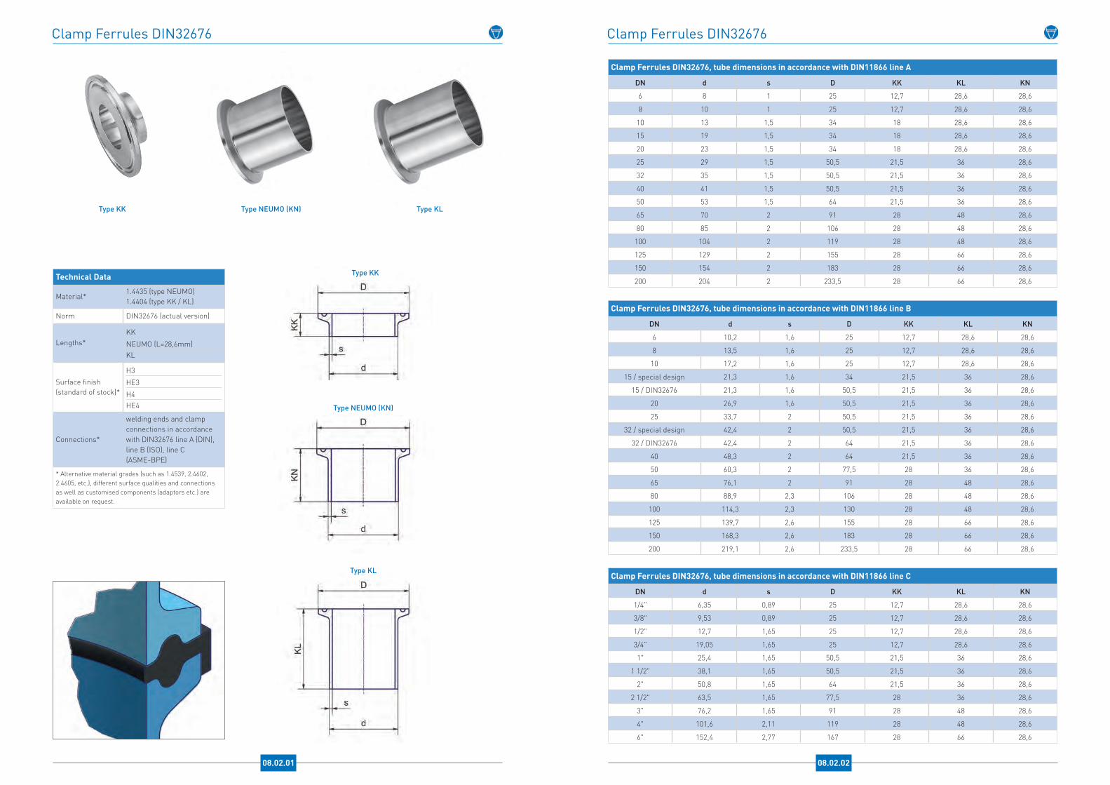
Clamp Ferrules DIN32676
08.02.01
Technical Data
Material*1.4435 (type NEUMO)1.4404 (type KK / KL)
Norm DIN32676 (actual version)
Lengths*KK
NEUMO (L=28,6mm)KL
Surface finish(standard of stock)*
H3
HE3
H4HE4
Connections*
welding ends and clamp connections in accordance with DIN32676 line A (DIN), line B (ISO), line C (ASME-BPE)
* Alternative material grades (such as 1.4539, 2.4602, 2.4605, etc.), different surface qualities and connections as well as customised components (adaptors etc.) are available on request.
Type KK
Type NEUMO (KN)
Type KL
Type NEUMO (KN) Type KL
Clamp Ferrules DIN32676
Clamp Ferrules DIN32676, tube dimensions in accordance with DIN11866 line A
DN d s D KK KL KN
6 8 1 25 12,7 28,6 28,6
8 10 1 25 12,7 28,6 28,6
10 13 1,5 34 18 28,6 28,6
15 19 1,5 34 18 28,6 28,6
20 23 1,5 34 18 28,6 28,6
25 29 1,5 50,5 21,5 36 28,6
32 35 1,5 50,5 21,5 36 28,6
40 41 1,5 50,5 21,5 36 28,6
50 53 1,5 64 21,5 36 28,6
65 70 2 91 28 48 28,6
80 85 2 106 28 48 28,6
100 104 2 119 28 48 28,6
125 129 2 155 28 66 28,6
150 154 2 183 28 66 28,6
200 204 2 233,5 28 66 28,6
Clamp Ferrules DIN32676, tube dimensions in accordance with DIN11866 line B
DN d s D KK KL KN
6 10,2 1,6 25 12,7 28,6 28,6
8 13,5 1,6 25 12,7 28,6 28,6
10 17,2 1,6 25 12,7 28,6 28,6
15 / special design 21,3 1,6 34 21,5 36 28,6
15 / DIN32676 21,3 1,6 50,5 21,5 36 28,6
20 26,9 1,6 50,5 21,5 36 28,6
25 33,7 2 50,5 21,5 36 28,6
32 / special design 42,4 2 50,5 21,5 36 28,6
32 / DIN32676 42,4 2 64 21,5 36 28,6
40 48,3 2 64 21,5 36 28,6
50 60,3 2 77,5 28 36 28,6
65 76,1 2 91 28 48 28,6
80 88,9 2,3 106 28 48 28,6
100 114,3 2,3 130 28 48 28,6
125 139,7 2,6 155 28 66 28,6
150 168,3 2,6 183 28 66 28,6
200 219,1 2,6 233,5 28 66 28,6
Clamp Ferrules DIN32676, tube dimensions in accordance with DIN11866 line C
DN d s D KK KL KN
1/4" 6,35 0,89 25 12,7 28,6 28,6
3/8" 9,53 0,89 25 12,7 28,6 28,6
1/2" 12,7 1,65 25 12,7 28,6 28,6
3/4" 19,05 1,65 25 12,7 28,6 28,6
1" 25,4 1,65 50,5 21,5 36 28,6
1 1/2" 38,1 1,65 50,5 21,5 36 28,6
2" 50,8 1,65 64 21,5 36 28,6
2 1/2" 63,5 1,65 77,5 28 36 28,6
3" 76,2 1,65 91 28 48 28,6
4" 101,6 2,11 119 28 48 28,6
6" 152,4 2,77 167 28 66 28,6
08.02.02
Type KK
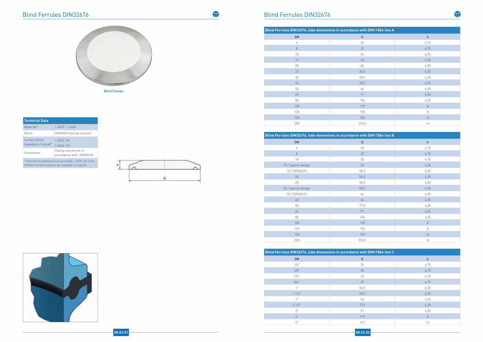
Blind Ferrules DIN32676
08.03.01
Technical Data
Material* 1.4435 / 1.4404
Norm DIN32676 (actual version)
Surface finish(standard of stock)*
1.4435: H4
1.4404: H3
ConnectionClamp connection in accordance with DIN32676
* Alternative materials (such as 2.4602, 1.4539, etc.) and different surface qualities are available on request.
Blind Clamps
Blind Ferrules DIN32676
08.03.02
Blind Ferrules DIN32676, tube dimensions in accordance with DIN11866 line A
DN D h
6 25 4,75
8 25 4,75
10 34 6,35
15 34 6,35
20 34 6,35
25 50,5 6,35
32 50,5 6,35
40 50,5 6,35
50 64 6,35
65 91 6,35
80 106 6,35
100 119 8
125 155 8
150 183 14
200 233,5 14
Blind Ferrules DIN32676, tube dimensions in accordance with DIN11866 line B
DN D h
6 25 4,75
8 25 4,75
10 25 4,75
15 / special design 34 6,35
15 / DIN32676 50,5 6,35
20 50,5 6,35
25 50,5 6,35
32 / special design 50,5 6,35
32 / DIN32676 64 6,35
40 64 6,35
50 77,5 6,35
65 91 6,35
80 106 6,35
100 130 8
125 155 8
150 183 14
200 233,5 14
Blind Ferrules DIN32676, tube dimensions in accordance with DIN11866 line C
DN D h
1/4" 25 4,75
3/8" 25 4,75
1/2" 25 4,75
3/4" 25 4,75
1" 50,5 6,35
1 1/2" 50,5 6,35
2" 64 6,35
2 1/2" 77,5 6,35
3" 91 6,35
4" 119 8
6" 167 14

Hose Tails
08.04.01
Technical Data
Material* 316L / 1.4404
Surface quality(standard of stock)*
Ra<0,8µm precision turned
Connections*
Clamp connection in accor-dance with DIN32676 line A (DIN), line B (ISO), line C (ASME-BPE)
* Alternative materials (such as 1.4435, 1.4539, 2.4602, 2.4605, AL-6XN®, etc.), different surface qualities and connections as well as customised components are available on request
Hose Tail
Hose Tail
Hose Tails
08.04.02
Hose Tails - connection in accordance with DIN32676 line A
Clamp Connection
Hose A B C D L
DN 10
1/4" 6,4 3,4 34 10 403/8" 9,5 6,5 34 10 401/2" 12,7 9,7 34 10 403/4" 19 16 34 10 40
DN 15
1/4" 6,4 3,4 34 16 403/8" 9,5 6,5 34 16 401/2" 12,7 9,7 34 16 403/4" 19 16 34 16 40
DN 20
1/4" 6,4 3,4 34 20 403/8" 9,5 6,5 34 20 401/2" 12,7 9,7 34 20 40
3/4" 19 16 34 20 0
Hose Tails - connection in accordance with DIN32676 line C / ASME-BPE
Clamp Connection
Hose A B C D L
1/2"
1/4" 6,4 3,4 25 10 328 x 5 8 5 25 10 323/8" 9,5 6,5 25 10 321/2" 12,7 9,7 25 10 32
14 x 11 14 11 25 10 4016 x 13 16 13 25 10 40
3/4" 19 16 25 10 32
3/4“
1/4" 6,4 3,4 25 10 328 x 5 8 5 25 10 323/8" 9,5 6,5 25 10 321/2" 12,7 9,7 25 10 32
14 x 11 14 11 25 10 4016 x 13 16 13 25 10 40
3/4" 19 16 25 10 32
1"
1/4" 6,4 3,4 50,5 23 408 x 5 8 5 50,5 23 403/8" 9,5 6,5 50,5 23 401/2" 12,7 9,7 50,5 23 40
14 x 11 14 11 50,5 23 4016 x 13 16 13 50,5 23 40
3/4" 19 16 50,5 23 4022 x 19 22 19 50,5 23 40
1" 26 23 50,5 23 40
1 1/2"
1/4" 6,4 3,4 50,5 35 408 x 5 8 5 50,5 35 403/8" 9,5 6,5 50,5 35 401/2" 12,7 9,7 50,5 35 40
14 x 11 14 11 50,5 35 4016 x 13 16 13 50,5 35 40
3/4" 19 16 50,5 35 4022 x 19 22 19 50,5 35 40
1" 26 23 50,5 35 401 1/2" 38,1 35 50,5 35 40
2"
1/2" 12,7 9,7 64 48 603/4" 19 16 64 48 601" 26 23 64 48 60
1 1/2" 38,1 35 64 48 60
2" 50,8 47 64 48 60Connection in accordance with DIN32676 line B (ISO) available on request .
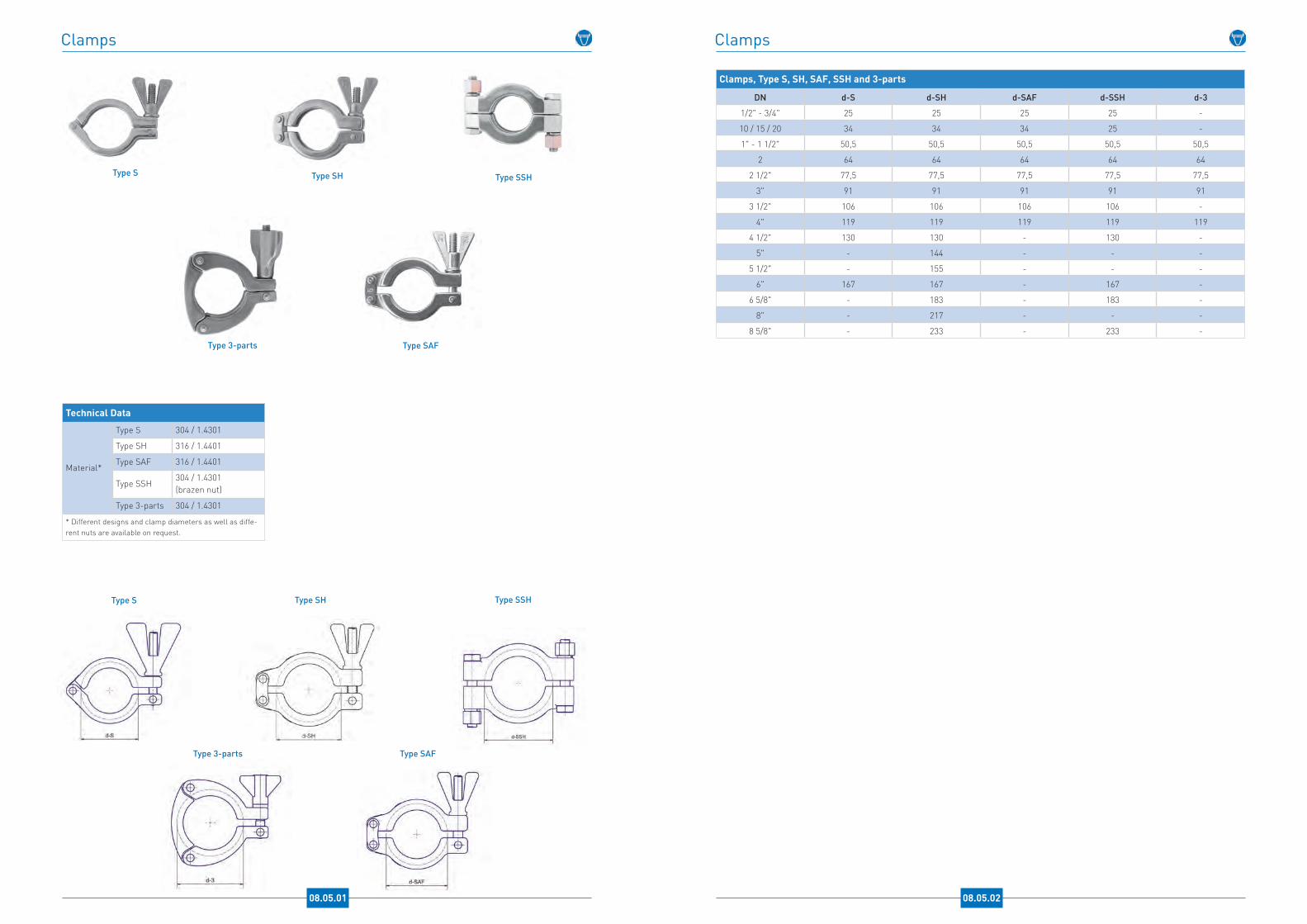
Clamps
08.05.01
Technical Data
Material*
Type S 304 / 1.4301
Type SH 316 / 1.4401
Type SAF 316 / 1.4401
Type SSH 304 / 1.4301 (brazen nut)
Type 3-parts 304 / 1.4301
* Different designs and clamp diameters as well as diffe-rent nuts are available on request.
Type 3-parts
Type SSH
Type SAF
Type SHType S
Type 3-parts
Type S Type SSHType SH
Type SAF
Clamps
08.05.02
Clamps, Type S, SH, SAF, SSH and 3-parts
DN d-S d-SH d-SAF d-SSH d-3
1/2" - 3/4" 25 25 25 25 -
10 / 15 / 20 34 34 34 25 -
1" - 1 1/2" 50,5 50,5 50,5 50,5 50,5
2 64 64 64 64 64
2 1/2" 77,5 77,5 77,5 77,5 77,5
3" 91 91 91 91 91
3 1/2" 106 106 106 106 -
4" 119 119 119 119 119
4 1/2" 130 130 - 130 -
5" - 144 - - -
5 1/2" - 155 - - -
6" 167 167 - 167 -
6 5/8" - 183 - 183 -
8" - 217 - - -
8 5/8" - 233 - 233 -
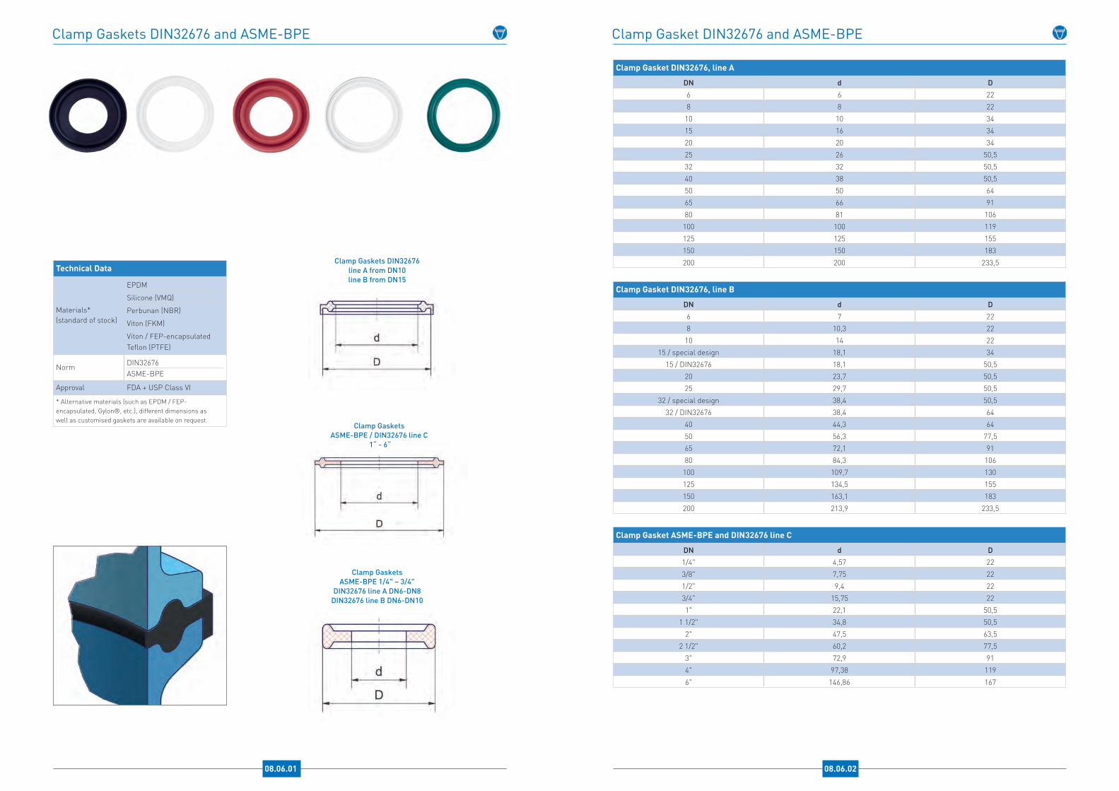
Clamp Gaskets DIN32676 and ASME-BPE
08.06.01
Clamp Gaskets DIN32676line A from DN10 line B from DN15
Clamp Gaskets ASME-BPE 1/4" – 3/4"
DIN32676 line A DN6-DN8DIN32676 line B DN6-DN10
Technical Data
Materials* (standard of stock)
EPDM
Silicone (VMQ)
Perbunan (NBR)
Viton (FKM)
Viton / FEP-encapsulatedTeflon (PTFE)
Norm DIN32676ASME-BPE
Approval FDA + USP Class VI
* Alternative materials (such as EPDM / FEP-encapsulated, Gylon®, etc.), different dimensions as well as customised gaskets are available on request.
Clamp GasketsASME-BPE / DIN32676 line C
1“ - 6“
Clamp Gasket DIN32676 and ASME-BPE
08.06.02
Clamp Gasket DIN32676, line A
DN d D6 6 228 8 22
10 10 3415 16 3420 20 3425 26 50,532 32 50,540 38 50,550 50 6465 66 9180 81 106
100 100 119125 125 155150 150 183
200 200 233,5
Clamp Gasket DIN32676, line B
DN d D6 7 228 10,3 22
10 14 2215 / special design 18,1 34
15 / DIN32676 18,1 50,520 23,7 50,525 29,7 50,5
32 / special design 38,4 50,532 / DIN32676 38,4 64
40 44,3 6450 56,3 77,565 72,1 9180 84,3 106
100 109,7 130125 134,5 155150 163,1 183
200 213,9 233,5
Clamp Gasket ASME-BPE and DIN32676 line C
DN d D1/4" 4,57 223/8" 7,75 221/2" 9,4 223/4" 15,75 221" 22,1 50,5
1 1/2" 34,8 50,52" 47,5 63,5
2 1/2" 60,2 77,53" 72,9 914" 97,38 119
6" 146,86 167

DIN11864Asepctic Tube Connections
Hygienic Class DIN11864
Hygienic classSurface qualitiesa
Ra internal surface Ra external surface
H1 HE1b -
H2 HE2b -
H3* HE3b <0,80µm <1,60µm
H4 HE4b <0,40µm <0,80µm
H5 HE5b <0,25µm <0,80µm
a Grooves of the elastomeric gaskets: Ra = 0,80 +/-0,20 µm.b Electropolished with a removal of at least 20µm* Standard hygienic class
09.01.01

Screwed Connection DIN11864-1 Form A and Blind Parts DIN11853
09.02.01
Technical Data
NormDIN11864-1 (liner and male part)
DIN11853-1 (blind parts)
Material* 1.4435 / 316L1.4404 / 316L
Surface finish (product contacted area)*
Ra < 0,8 µm precision turned
Sealing*EPDM / FDA + USP Class VI (form A)
Delta ferrite con-tent(raw material)*
< 1% (1.4435)
Connections*
Orbital welding ends in ac-cordance with DIN11866 line A (DIN), line B (ISO), line C (ASME-BPE)
* Alternative material grades (such as 2.4602, 2.4605, 1.4539, AL-6XN®, titanium, etc.), alternative sealings (z.B. Viton, Viton / FEP-encapsulated, PTFE, etc.) as well as different connections, surface qualities and delta ferrite values are available on request.
Blind Male Part Blind Liner
Liner
Male Part
Blind Liner
Male Part
O-Ring
Screwed Connection DIN11864-1 Form A and Blind Parts DIN11853
Screwed Connection DIN11864-1 form A / Blind Male Part and Blind Liner DIN11853-1, tube dimensions in accordance with DIN11866 line A
DN d s D Rd DB L LG LB t BG BB SW ID x S
10 13 1,5 38 Rd 28 x 1/8 21,9 76 41 39 4 24 9 17 12 x 3,5
15 19 1,5 44 Rd 34 x 1/8 27,9 76 41 39 4 24 9 17 18 x 3,5
20 23 1,5 54 Rd 44 x 1/6 35,9 76 43 38 5 24 10 17 22 x 3,5
25 29 1,5 63 Rd 52 x 1/6 42,9 77 43 40 6 24 12 27 28 x 3,5
32 35 1,5 70 Rd 58 x 1/6 48,9 88 48 47 7 24 13 27 34 x 5
40 41 1,5 78 Rd 65 x 1/6 54,9 88 48 47 7 24 13 27 40 x 5
50 53 1,5 92 Rd 78 x 1/6 66,9 89 48 48 7 24 14 27 52 x 5
65 70 2 112 Rd 95 x 1/6 84,9 113 60 61 8 28 16 32 68 x 5
80 85 2 127 Rd 110 x 1/4 98,9 117 64 61 8 28 16 32 83 x 5
100 104 2 148 Rd 130 x 1/4 118,9 120 64 66 10 30 20 32 102 x 5
Screwed Connection DIN11864-1 form A / Blind Male Part and Blind Liner DIN11853-1, tube dimensions in accordance with DIN11866 line B
DN d s D Rd DB L LG LB t BG BB SW ID x S
8 13,5 1,6 38 Rd 28 x 1/8 21,9 76 41 39 4 24 9 17 12 x 3,5
10 17,2 1,6 44 Rd 34 x 1/8 27,9 76 41 39 4 24 9 17 16 x 3,5
15 21,3 1,6 54 Rd 44 x 1/6 35,9 78 43 40 5 24 10 17 20 x 3,5
20 26,9 1,6 63 Rd 52 x 1/6 42,9 78 43 41 6 24 12 27 26 x 3,5
25 33,7 2 70 Rd 58 x 1/6 48,9 88 48 47 7 24 13 27 32 x 5
32 42,4 2 78 Rd 65 x 1/6 54,9 88 48 47 7 24 13 27 40,5 x 5
40 48,3 2 92 Rd 78 x 1/6 66,9 90 49 48 7 24 14 27 46,5 x 5
50 60,3 2 112 Rd 95 x 1/6 84,9 114 60 62 8 28 16 32 58,5 x 5
65 76,1 2 127 Rd 110 x 1/4 98,9 117 64 61 8 28 16 32 73,5 x 5
80 88,9 2,3 148 Rd 130 x 1/4 118,9 122 64 68 10 30 20 32 86,5 x 5
Screwed Connection DIN11864-1 form A / Blind Male Part and Blind Liner DIN11853-1, tube dimensions in accordance with DIN11866 line C
DN d s D Rd DB L LG LB t BG BB SW ID x S
1/2" 12,7 1,65 38 Rd 28 x 1/8 21,9 76 41 39 4 24 9 17 12 x 3,5
3/4" 19,05 1,65 44 Rd 34 x 1/8 27,9 76 41 39 4 24 9 17 18 x 3,5
1" 25,4 1,65 63 Rd 52 x 1/6 42,9 77 43 40 6 24 12 27 24 x 3,5
1 1/2" 38,1 1,65 78 Rd 65 x 1/6 54,9 88 48,5 46,5 7 24 13 27 37 x 5
2" 50,8 1,65 92 Rd 78 x 1/6 66,9 89 48,5 47,5 7 24 14 27 50 x 5
2 1/2" 63,5 1,65 112 Rd 95 x 1/6 84,9 115 60 63 8 28 16 32 62 x 5
3" 76,2 1,65 127 Rd 110 x 1/4 98,9 117 64 61 8 28 16 32 75 x 5
4" 101,6 2,11 148 Rd 130 x 1/4 118,9 119 64 65 10 30 20 32 100 x 5
09.02.02
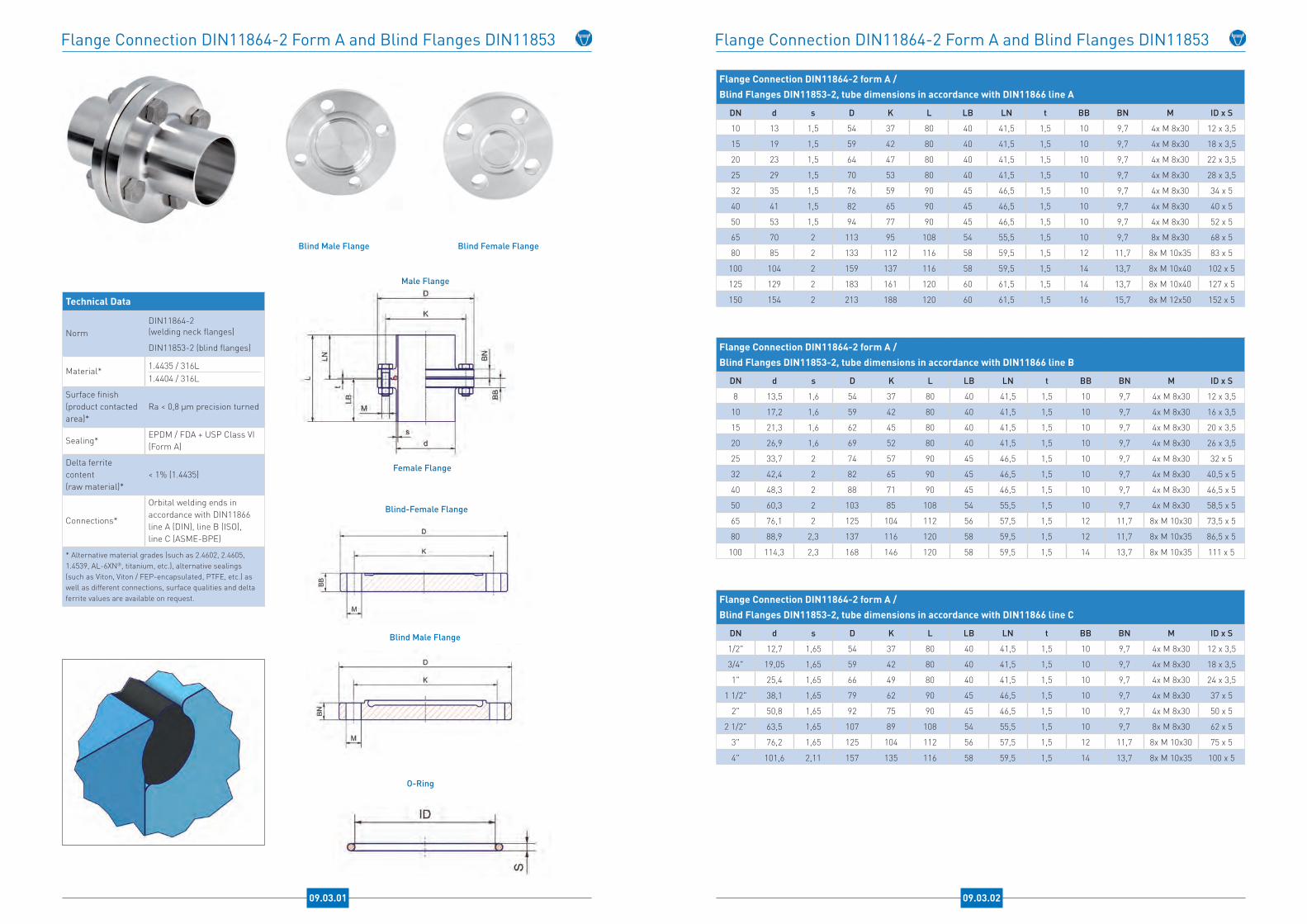
Flange Connection DIN11864-2 Form A and Blind Flanges DIN11853
09.03.01
Technical Data
NormDIN11864-2 (welding neck flanges)
DIN11853-2 (blind flanges)
Material* 1.4435 / 316L1.4404 / 316L
Surface finish (product contacted area)*
Ra < 0,8 µm precision turned
Sealing*EPDM / FDA + USP Class VI (Form A)
Delta ferrite content(raw material)*
< 1% (1.4435)
Connections*
Orbital welding ends in accordance with DIN11866 line A (DIN), line B (ISO), line C (ASME-BPE)
* Alternative material grades (such as 2.4602, 2.4605, 1.4539, AL-6XN®, titanium, etc.), alternative sealings (such as Viton, Viton / FEP-encapsulated, PTFE, etc.) as well as different connections, surface qualities and delta ferrite values are available on request.
Blind Male Flange Blind Female Flange
Blind Male Flange
O-Ring
Male Flange
Female Flange
Flange Connection DIN11864-2 Form A and Blind Flanges DIN11853
Flange Connection DIN11864-2 form A / Blind Flanges DIN11853-2, tube dimensions in accordance with DIN11866 line A
DN d s D K L LB LN t BB BN M ID x S
10 13 1,5 54 37 80 40 41,5 1,5 10 9,7 4x M 8x30 12 x 3,5
15 19 1,5 59 42 80 40 41,5 1,5 10 9,7 4x M 8x30 18 x 3,5
20 23 1,5 64 47 80 40 41,5 1,5 10 9,7 4x M 8x30 22 x 3,5
25 29 1,5 70 53 80 40 41,5 1,5 10 9,7 4x M 8x30 28 x 3,5
32 35 1,5 76 59 90 45 46,5 1,5 10 9,7 4x M 8x30 34 x 5
40 41 1,5 82 65 90 45 46,5 1,5 10 9,7 4x M 8x30 40 x 5
50 53 1,5 94 77 90 45 46,5 1,5 10 9,7 4x M 8x30 52 x 5
65 70 2 113 95 108 54 55,5 1,5 10 9,7 8x M 8x30 68 x 5
80 85 2 133 112 116 58 59,5 1,5 12 11,7 8x M 10x35 83 x 5
100 104 2 159 137 116 58 59,5 1,5 14 13,7 8x M 10x40 102 x 5
125 129 2 183 161 120 60 61,5 1,5 14 13,7 8x M 10x40 127 x 5
150 154 2 213 188 120 60 61,5 1,5 16 15,7 8x M 12x50 152 x 5
Flange Connection DIN11864-2 form A / Blind Flanges DIN11853-2, tube dimensions in accordance with DIN11866 line B
DN d s D K L LB LN t BB BN M ID x S
8 13,5 1,6 54 37 80 40 41,5 1,5 10 9,7 4x M 8x30 12 x 3,5
10 17,2 1,6 59 42 80 40 41,5 1,5 10 9,7 4x M 8x30 16 x 3,5
15 21,3 1,6 62 45 80 40 41,5 1,5 10 9,7 4x M 8x30 20 x 3,5
20 26,9 1,6 69 52 80 40 41,5 1,5 10 9,7 4x M 8x30 26 x 3,5
25 33,7 2 74 57 90 45 46,5 1,5 10 9,7 4x M 8x30 32 x 5
32 42,4 2 82 65 90 45 46,5 1,5 10 9,7 4x M 8x30 40,5 x 5
40 48,3 2 88 71 90 45 46,5 1,5 10 9,7 4x M 8x30 46,5 x 5
50 60,3 2 103 85 108 54 55,5 1,5 10 9,7 4x M 8x30 58,5 x 5
65 76,1 2 125 104 112 56 57,5 1,5 12 11,7 8x M 10x30 73,5 x 5
80 88,9 2,3 137 116 120 58 59,5 1,5 12 11,7 8x M 10x35 86,5 x 5
100 114,3 2,3 168 146 120 58 59,5 1,5 14 13,7 8x M 10x35 111 x 5
Flange Connection DIN11864-2 form A / Blind Flanges DIN11853-2, tube dimensions in accordance with DIN11866 line C
DN d s D K L LB LN t BB BN M ID x S
1/2" 12,7 1,65 54 37 80 40 41,5 1,5 10 9,7 4x M 8x30 12 x 3,5
3/4" 19,05 1,65 59 42 80 40 41,5 1,5 10 9,7 4x M 8x30 18 x 3,5
1" 25,4 1,65 66 49 80 40 41,5 1,5 10 9,7 4x M 8x30 24 x 3,5
1 1/2" 38,1 1,65 79 62 90 45 46,5 1,5 10 9,7 4x M 8x30 37 x 5
2" 50,8 1,65 92 75 90 45 46,5 1,5 10 9,7 4x M 8x30 50 x 5
2 1/2" 63,5 1,65 107 89 108 54 55,5 1,5 10 9,7 8x M 8x30 62 x 5
3" 76,2 1,65 125 104 112 56 57,5 1,5 12 11,7 8x M 10x30 75 x 5
4" 101,6 2,11 157 135 116 58 59,5 1,5 14 13,7 8x M 10x35 100 x 5
09.03.02
Blind-Female Flange

Clamp Connection DIN11864-3 Form A and Blind Ferrules DIN11853
09.04.01
Technical Data
NormDIN11864-3 (clamp ferrules)DIN11853-3 (blind ferrules)
Material* 1.4435 / 316L1.4404 / 316L
Surface finish (product contacted areas)
Ra < 0,8 µm precision turned
Sealing*EPDM / FDA + USP Class VI (Form A)
Delta ferrite cont-ent (raw material)*
< 1% (1.4435)
Connections*
Orbital welding ends in accordance with DIN11866 line A (DIN), line B (ISO), line C (ASME-BPE)
* Alternative material grades (such as 2.4602, 2.4605, 1.4539, AL-6XN®, titanium, etc.), alternative sealings, (such as Viton, Viton / FEP-encapsulated, PTFE, etc.) as well as different connections, surface qualities and delta ferrite values are available on request
Blind Male Ferrule Blind Female Ferrule
Blind Female Ferrule
Blind Male Ferrule
O-Ring
Male Clamp Ferrule
Female Clamp Ferrule
Clamp Connection DIN11864-3 Form A und Blind Ferrules DIN11853
Clamp Connection DIN11864-3 form A / Blind Ferrules DIN11853-3, tube dimensions in accordance with DIN11866 line A
DN d s D L LB LN t BB BN ID x S
10 13 1,5 34 76 38 39,5 1,5 11,5 13 12 x 3,5
15 19 1,5 34 76 38 39,5 1,5 11,5 13 18 x 3,5
20 23 1,5 50,5 76 38 39,5 1,5 11,5 13 22 x 3,5
25 29 1,5 50,5 77 38,5 40 1,5 11,5 13 28 x 3,5
32 35 1,5 50,5 88 44 45,5 1,5 11,5 13 34 x 5
40 41 1,5 64 88 44 45,5 1,5 11,5 13 40 x 5
50 53 1,5 77,5 89 44,5 46 1,5 13,5 15 52 x 5
65 70 2 91 113 56,5 58 1,5 13,5 15 68 x 5
80 85 2 106 117 58,5 60 1,5 13,5 15 83 x 5
100 104 2 130 120 60 61,5 1,5 13,5 15 102 x 5
Clamp Connection DIN11864-3 form A / Blind Ferrules DIN11853-3, tube dimensions in accordance with DIN11866 line B
DN d s D L LB LN t BB BN ID x S
8 13,5 1,6 34 76 38 39,5 1,5 11,5 13 12 x 3,5
10 17,2 1,6 34 76 38 39,5 1,5 11,5 13 16 x 3,5
15 21,3 1,6 34 78 39 40,5 1,5 11,5 13 20 x 3,5
20 26,9 1,6 50,5 78 39 40 1,5 11,5 13 26 x 3,5
25 33,7 2 50,5 88 44 45,5 1,5 11,5 13 32 x 5
32 42,4 2 64 88 44 45,5 1,5 11,5 13 40,5 x 5
40 48,3 2 64 90 45 46,5 1,5 11,5 13 46,5 x 5
50 60,3 2 91 114 57 58,5 1,5 13,5 15 58,5 x 5
65 76,1 2 106 117 58,5 60 1,5 13,5 15 73,5 x 5
80 88,9 2,3 119 122 61 62,5 1,5 13,5 15 86,5 x 5
Clamp Connection DIN11864-3 form A / Blind Ferrules DIN11853-3, tube dimensions in accordance with DIN11866 line C
DN d s D L LB LN t BB BN ID x S
1/2" 12,7 1,65 34 76 38 39,5 1,5 11,5 13 12 x 3,5
3/4" 19,05 1,65 34 76 38 39,5 1,5 11,5 13 18 x 3,5
1" 25,4 1,65 50,5 77 38,5 40 1,5 11,5 13 24 x 3,5
1 1/2" 38,1 1,65 64 88 44 45,5 1,5 11,5 13 37 x 5
2" 50,8 1,65 77,5 89 44,5 46 1,5 13,5 15 50 x 5
2 1/2" 63,5 1,65 91 115 57,5 59 1,5 13,5 15 62 x 5
3" 76,2 1,65 106 117 58,5 60 1,5 13,5 15 75 x 5
4" 101,6 2,11 130 119 59,5 61 1,5 13,5 15 100 x 5
09.04.02
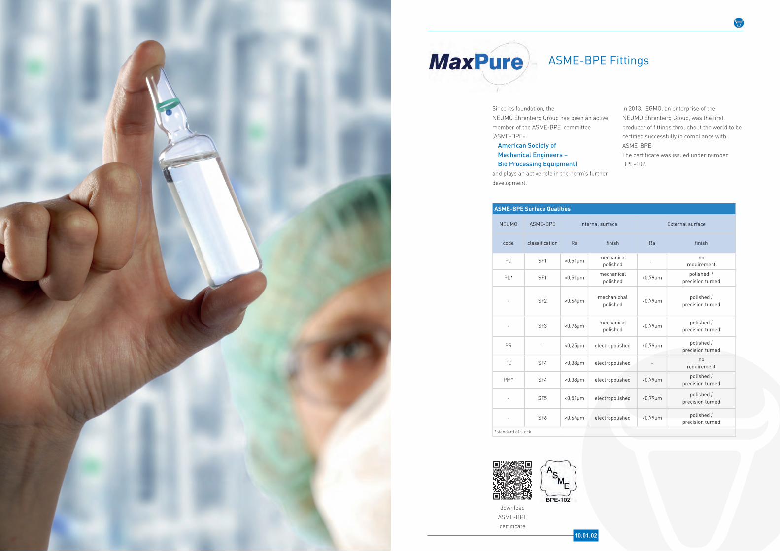
In 2013, EGMO, an enterprise of the NEUMO Ehrenberg Group, was the first producer of fittings throughout the world to be certified successfully in compliance with ASME-BPE. The certificate was issued under number BPE-102.
Since its foundation, the NEUMO Ehrenberg Group has been an active member of the ASME-BPE committee (ASME-BPE=
American Society of Mechanical Engineers – Bio Processing Equipment)
and plays an active role in the norm‘s further development.
ASME-BPE Fittings
ASME-BPE Surface Qualities
NEUMO ASME-BPE Internal surface External surface
code classification Ra finish Ra finish
PC SF1 <0,51µmmechanical
polished-
no requirement
PL* SF1 <0,51µmmechanical
polished<0,79µm
polished / precision turned
- SF2 <0,64µmmechanichal
polished<0,79µm
polished /precision turned
- SF3 <0,76µmmechanical
polished<0,79µm
polished / precision turned
PR - <0,25µm electropolished <0,79µm polished / precision turned
PD SF4 <0,38µm electropolished -no
requirement
PM* SF4 <0,38µm electropolished <0,79µmpolished /
precision turned
- SF5 <0,51µm electropolished <0,79µmpolished /
precision turned
- SF6 <0,64µm electropolished <0,79µm polished /precision turned
*standard of stock
download ASME-BPE certificate
10.01.02

Elbows ASME-BPE 90° / 45°, Type WW
10.02.01
Technical Data
Material* 316L
NormASME-BPE
(actual version)
BPE table 90°: DT-4.1.1-145°: DT-4.1.1-4
Material code 90°: TE2S45°: TE2KS
Surface finish(standard of stock)*
SF1SF4
ConnectionsOrbital welding ends in accordance with ASME-BPE
* Alternative material grades (such as 2.4602, AL-6XN®, etc.), different surface qualities as well as special elbows (88°, 92°, 30°, 60°, etc.) are available on request.
TE2S TE2KS
TE2KS
TE2S
Elbow ASME-BPE 90° / 45°, Type WW
Elbow ASME-BPE 90° / 45°, orbital welding ends on both sides
DN d s R l1 l2
1/4" 6,35 0,89 14,3 66,7 50,8
3/8" 9,53 0,89 28,58 66,7 50,8
1/2" 12,7 1,65 28,58 76,2 57,2
3/4" 19,05 1,65 28,58 76,2 57,2
1" 25,4 1,65 38,1 76,2 57,2
1 1/2" 38,1 1,65 57,15 95,3 63,5
2" 50,8 1,65 76,2 120,7 76,2
2 1/2" 63,5 1,65 95,25 139,7 85,7
3" 76,2 1,65 114,3 158,8 92,1
4" 101,6 2,11 152,4 203,2 114,3
6" 152,4 2,77 228,6 292,1 158,8
10.02.02

Elbow ASME-BPE 90° / 45°, Type CW
10.03.01
Technical Data
Material* 316L
NormASME-BPE
(actual version)
BPE table 90°: DT-4.1.1-245°: DT-4.1.1-5
Material code 90°: TE2C45°: TE2KC
Surface finish(standard of stock)*
SF1SF4
Connection 1 Orbital welding end in accordance with ASME-BPE
Connection 2Clamp connection in accordance with ASME-BPE
* Alternative material grades such as 2.4602, AL-6XN®, etc.), different surface qualities as well as special elbows (88°, 92°, 30°, 60°, etc.) are available on request
TE2C TE2KC
TE2KC
TE2C
Elbow ASME-BPE 90° / 45°, Type CW
Elbow ASME-BPE 90° and 45°, clamp connection / orbital welding end
DN d s R l1 l2 l3 l4 D
1/4" 6,35 0,89 14,3 66,7 41,3 50,8 25,4 25
3/8" 9,53 0,89 28,58 66,7 41,3 50,8 25,4 25
1/2" 12,7 1,65 28,58 76,2 41,3 57,2 25,4 25
3/4" 19,05 1,65 28,58 76,2 41,3 57,2 25,4 25
1" 25,4 1,65 38,1 76,2 50,8 57,2 28,6 50,4
1 1/2" 38,1 1,65 57,15 95,3 69,9 63,5 36,5 50,4
2" 50,8 1,65 76,2 120,7 88,9 76,2 44,5 64
2 1/2" 63,5 1,65 95,25 139,7 108 85,7 52,4 77,4
3" 76,2 1,65 114,3 158,8 127 92,1 60,3 91
4" 101,6 2,11 152,4 203,2 168,3 114,3 79,4 119
6" 152,4 2,77 228,6 292,1 266,7 158,8 133,4 167
10.03.02
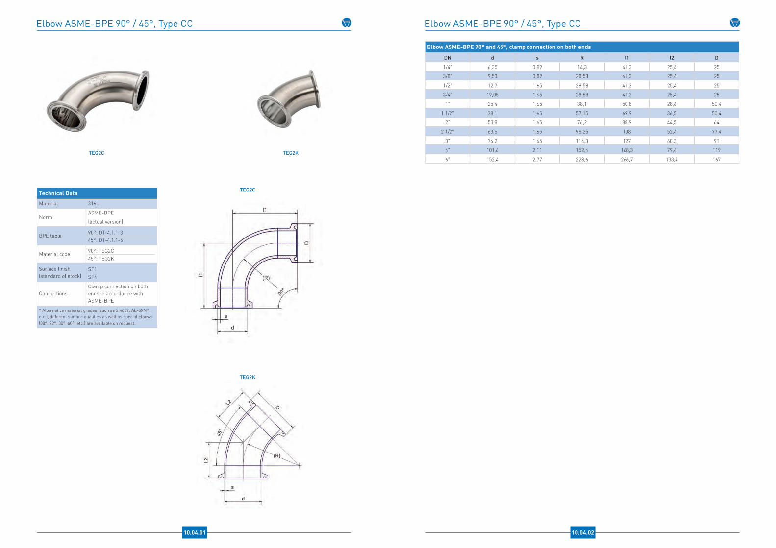
Elbow ASME-BPE 90° / 45°, Type CC
10.04.01
Technical Data
Material 316L
NormASME-BPE
(actual version)
BPE table 90°: DT-4.1.1-345°: DT-4.1.1-6
Material code 90°: TEG2C45°: TEG2K
Surface finish(standard of stock)
SF1SF4
ConnectionsClamp connection on both ends in accordance with ASME-BPE
* Alternative material grades (such as 2.4602, AL-6XN®, etc.), different surface qualities as well as special elbows (88°, 92°, 30°, 60°, etc.) are available on request.
TEG2C TEG2K
TEG2K
TEG2C
Elbow ASME-BPE 90° / 45°, Type CC
Elbow ASME-BPE 90° and 45°, clamp connection on both ends
DN d s R l1 l2 D
1/4" 6,35 0,89 14,3 41,3 25,4 25
3/8" 9,53 0,89 28,58 41,3 25,4 25
1/2" 12,7 1,65 28,58 41,3 25,4 25
3/4" 19,05 1,65 28,58 41,3 25,4 25
1" 25,4 1,65 38,1 50,8 28,6 50,4
1 1/2" 38,1 1,65 57,15 69,9 36,5 50,4
2" 50,8 1,65 76,2 88,9 44,5 64
2 1/2" 63,5 1,65 95,25 108 52,4 77,4
3" 76,2 1,65 114,3 127 60,3 91
4" 101,6 2,11 152,4 168,3 79,4 119
6" 152,4 2,77 228,6 266,7 133,4 167
10.04.02

Tee-Piece long equal / reduced ASME-BPE, Type WWW
10.05.01
Technical Data
Material 316L
NormASME-BPE
(actual version)
BPE table Tee-Piece: DT-4.1.2-1Red.-Tee-Piece: DT-4.1.2-6
Material code Tee-Piece: TE7WWWRed.-Tee-Piece: TE7RWWW
Surface finish(standard of stock)*
SF1SF4
ConnectionsOrbital welding ends in accordance with ASME-BPE
* Alternative material grades (such as 2.4602, AL-6XN®, etc.) and different surface qualities are available on request.
TE7WWW TE7RWWW
TE7RWWW
TE7WWW
Tee-Piece long equal / reduced ASME-BPE, Type WWW
Tee-Piece long equal / reduced ASME-BPE, orbital welding ends on all sides
DN d1 s1 d2 s2 L lo l2
1/4" 6,35 0,89 6,35 0,89 89 44,5 44,5
3/8" / 1/4" 9,53 0,89 6,35 0,89 89 44,5 44,5
3/8" 9,53 0,89 9,53 0,89 89 44,5 44,5
1/2" / 1/4" 12,7 1,65 6,35 0,89 95,2 47,6 47,6
1/2" / 3/8" 12,7 1,65 9,53 0,89 95,2 47,6 47,6
1/2" 12,7 1,65 12,7 1,65 95,2 47,6 47,6
3/4" / 1/4" 19,05 1,65 6,35 0,89 101,6 50,8 50,8
3/4" / 3/8" 19,05 1,65 9,53 0,89 101,6 50,8 50,8
3/4" / 1/2" 19,05 1,65 12,7 1,65 101,6 50,8 50,8
3/4" 19,05 1,65 19,05 1,65 101,6 50,8 50,8
1" / 1/4" 25,4 1,65 6,35 0,89 108 54 54
1" / 3/8" 25,4 1,65 9,53 0,89 108 54 54
1" / 1/2" 25,4 1,65 12,7 1,65 108 54 54
1" / 3/4" 25,4 1,65 19,05 1,65 108 54 54
1" 25,4 1,65 25,4 1,65 108 54 54
1 1/2" / 1/2" 38,1 1,65 12,7 1,65 120,6 60,3 60,3
1 1/2" / 3/4" 38,1 1,65 19,05 1,65 120,6 60,3 60,3
1 1/2" / 1" 38,1 1,65 25,4 1,65 120,6 60,3 60,3
1 1/2" 38,1 1,65 38,1 1,65 120,6 60,3 60,3
2" / 1/2" 50,8 1,65 12,7 1,65 146 73 66,7
2" / 3/4" 50,8 1,65 19,05 1,65 146 73 66,7
2" / 1" 50,8 1,65 25,4 1,65 146 73 66,7
2" / 1 1/2" 50,8 1,65 38,1 1,65 146 73 66,7
2" 50,8 1,65 50,8 1,65 146 73 73
2 1/2" / 1/2" 63,5 1,65 12,7 1,65 158,8 79,4 73
2 1/2" /3/4" 63,5 1,65 19,05 1,65 158,8 79,4 73
2 1/2" / 1" 63,5 1,65 25,4 1,65 158,8 79,4 73
2 1/2" / 1 1/2" 63,5 1,65 38,1 1,65 158,8 79,4 73
2 1/2" / 2" 63,5 1,65 50,8 1,65 158,8 79,4 73
2 1/2" 63,5 1,65 63,5 1,65 158,8 79,4 79,4
3" / 1/2" 76,2 1,65 12,7 1,65 171,4 85,7 79,4
3" / 3/4" 76,2 1,65 19,05 1,65 171,4 85,7 79,4
3" / 1" 76,2 1,65 25,4 1,65 171,4 85,7 79,4
3" / 1 1/2" 76,2 1,65 38,1 1,65 171,4 85,7 79,4
3" / 2" 76,2 1,65 50,8 1,65 171,4 85,7 79,4
3" / 2 1/2" 76,2 1,65 63,5 1,65 171,4 85,7 79,4
3" 76,2 1,65 76,2 1,65 171,4 85,7 85,7
4" / 1/2" 101,6 2,11 12,7 1,65 209,6 104,8 92,1
4" / 3/4" 101,6 2,11 19,05 1,65 209,6 104,8 92,1
4" / 1" 101,6 2,11 25,4 1,65 209,6 104,8 92,1
4" / 1 1/2" 101,6 2,11 38,1 1,65 209,6 104,8 92,1
4" / 2" 101,6 2,11 50,8 1,65 209,6 104,8 98,4
4" / 2 1/2" 101,6 2,11 63,5 1,65 209,6 104,8 98,4
4" / 3" 101,6 2,11 76,2 1,65 209,6 104,8 98,4
4" 101,6 2,11 101,6 2,11 209,6 104,8 104,8
6" / 3" 152,4 2,77 76,2 1,65 285,8 142,9 123,8
6" / 4" 152,4 2,77 101,6 2,11 285,8 142,9 130,2
6" 152,4 2,77 152,4 2,77 285,8 142,9 142,9
10.05.02

RUN-Tee-Piece short + Tee-Pieces for Instruments ASME-BPE
10.06.01
Technical Data
Material* 316L
NormASME-BPE
(actual version)
BPE table
RUN-Tee-Piece short: DT-4.1.2-3
Tee-Piece for instruments WWC: DT-4.1.2-10Tee-Piece for instruments CCC: DT-4.1.2-11
Material code
RUN-Tee-Piece short: TE7WCSW
Tee-Piece for instruments WWC:TE7IWWCSTee-Piece for instruments CCC: TEG7IS
Surface finish(standard of stock)
SF1SF4
* Alternative material grades (such as 2.4602, AL-6XN®, etc.), as well as different surface qualities are available on request.
TE7WCSW
TE7WCSW
TE7IWWCS
TEG7IS
TE7IWWCS TEG7IS
RUN-Tee-Piece short + Tee-Piece for Instruments ASME-BPE
Tee-Piece for Instruments ASME-BPE - TE7IWWCS
DN d1 s1 d2 s2 D2 L1 l1 l2
1/2" / 1 1/2" 12,7 1,65 38,1 1,65 50,4 127 63,5 22,2
1/2" / 2" 12,7 1,65 50,8 1,65 63,9 139,8 69,9 25,4
3/4" / 1 1/2" 19,05 1,65 38,1 1,65 50,4 127 63,5 25,4
3/4" / 2" 19,05 1,65 50,8 1,65 63,9 139,8 69,9 28,6
1" / 1 1/2" 25,4 1,65 38,1 1,65 50,4 127 63,5 28,6
1" / 2" 25,4 1,65 50,8 1,65 63,9 139,8 69,9 31,8
1 1/2" / 2" 38,1 1,65 50,8 1,65 63,9 139,8 69,9 38,1
Tee-Piece for Instruments ASME-BPE - TEG7IS
DN d1 s1 d2 s2 D1 D2 L2 l2 l3
1/2" / 1 1/2" 12,7 1,65 38,1 1,65 25 50,5 152,4 22,2 76,2
1/2" / 2" 12,7 1,65 50,8 1,65 25 64 165,2 25,4 82,6
3/4" / 1 1/2" 19,05 1,65 38,1 1,65 25 50,5 152,4 25,4 76,2
3/4" / 2" 19,05 1,65 50,8 1,65 25 64 165,2 28,6 82,6
1" / 1 1/2" 25,4 1,65 38,1 1,65 50,5 50,5 152,4 28,6 76,2
1" / 2" 25,4 1,65 50,8 1,65 50,5 64 165,2 31,8 82,6
1 1/2" / 2" 38,1 1,65 50,8 1,65 50,5 64 165,4 38,1 82,6
RUN-Tee-Piece short ASME-BPE - TE7WCSW
DN d1 s1 D1 L1 l1 l2
1/4" 6,35 0,89 25 66,7 44,5 22,2
3/8" 9,53 0,89 25 66,7 44,5 22,2
1/2" 12,7 1,65 25 69,8 47,6 22,2
3/4" 19,05 1,65 25 76,2 50,8 25,4
1" 25,4 1,65 50,5 82,6 54 28,6
1 1/2" 38,1 1,65 50,5 95,2 60,3 34,9
2" 50,8 1,65 64 114,3 73 41,3
2 1/2" 63,5 1,65 77,5 127 79,4 47,6
3" 76,2 1,65 91 139,7 85,7 54
4" 101,6 2,11 119 174,7 104,8 69,9
6" 152,4 2,77 167 260,5 142,9 117,5
10.06.02
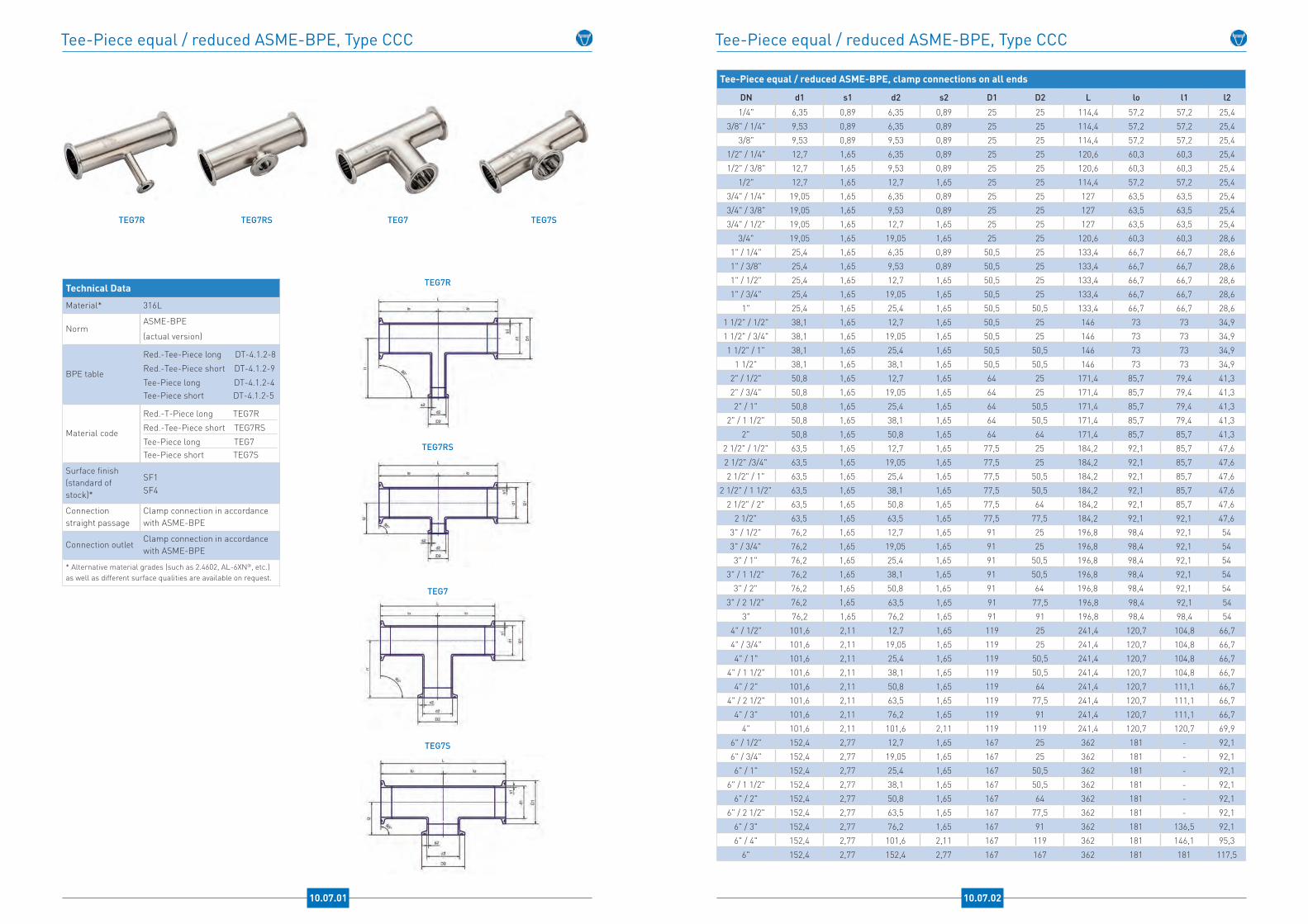
Tee-Piece equal / reduced ASME-BPE, Type CCC
10.07.01
Technical Data
Material* 316L
NormASME-BPE
(actual version)
BPE table
Red.-Tee-Piece long DT-4.1.2-8
Red.-Tee-Piece short DT-4.1.2-9
Tee-Piece long DT-4.1.2-4Tee-Piece short DT-4.1.2-5
Material code
Red.-T-Piece long TEG7R
Red.-Tee-Piece short TEG7RS
Tee-Piece long TEG7Tee-Piece short TEG7S
Surface finish(standard of stock)*
SF1SF4
Connection straight passage
Clamp connection in accordance with ASME-BPE
Connection outletClamp connection in accordance with ASME-BPE
* Alternative material grades (such as 2.4602, AL-6XN®, etc.) as well as different surface qualities are available on request.
TEG7R TEG7RS TEG7 TEG7S
TEG7R
TEG7RS
TEG7
TEG7S
Tee-Piece equal / reduced ASME-BPE, Type CCC
Tee-Piece equal / reduced ASME-BPE, clamp connections on all ends
DN d1 s1 d2 s2 D1 D2 L lo l1 l2
1/4" 6,35 0,89 6,35 0,89 25 25 114,4 57,2 57,2 25,43/8" / 1/4" 9,53 0,89 6,35 0,89 25 25 114,4 57,2 57,2 25,4
3/8" 9,53 0,89 9,53 0,89 25 25 114,4 57,2 57,2 25,41/2" / 1/4" 12,7 1,65 6,35 0,89 25 25 120,6 60,3 60,3 25,41/2" / 3/8" 12,7 1,65 9,53 0,89 25 25 120,6 60,3 60,3 25,4
1/2" 12,7 1,65 12,7 1,65 25 25 114,4 57,2 57,2 25,43/4" / 1/4" 19,05 1,65 6,35 0,89 25 25 127 63,5 63,5 25,43/4" / 3/8" 19,05 1,65 9,53 0,89 25 25 127 63,5 63,5 25,43/4" / 1/2" 19,05 1,65 12,7 1,65 25 25 127 63,5 63,5 25,4
3/4" 19,05 1,65 19,05 1,65 25 25 120,6 60,3 60,3 28,61" / 1/4" 25,4 1,65 6,35 0,89 50,5 25 133,4 66,7 66,7 28,61" / 3/8" 25,4 1,65 9,53 0,89 50,5 25 133,4 66,7 66,7 28,61" / 1/2" 25,4 1,65 12,7 1,65 50,5 25 133,4 66,7 66,7 28,61" / 3/4" 25,4 1,65 19,05 1,65 50,5 25 133,4 66,7 66,7 28,6
1" 25,4 1,65 25,4 1,65 50,5 50,5 133,4 66,7 66,7 28,61 1/2" / 1/2" 38,1 1,65 12,7 1,65 50,5 25 146 73 73 34,91 1/2" / 3/4" 38,1 1,65 19,05 1,65 50,5 25 146 73 73 34,91 1/2" / 1" 38,1 1,65 25,4 1,65 50,5 50,5 146 73 73 34,9
1 1/2" 38,1 1,65 38,1 1,65 50,5 50,5 146 73 73 34,92" / 1/2" 50,8 1,65 12,7 1,65 64 25 171,4 85,7 79,4 41,32" / 3/4" 50,8 1,65 19,05 1,65 64 25 171,4 85,7 79,4 41,32" / 1" 50,8 1,65 25,4 1,65 64 50,5 171,4 85,7 79,4 41,3
2" / 1 1/2" 50,8 1,65 38,1 1,65 64 50,5 171,4 85,7 79,4 41,32" 50,8 1,65 50,8 1,65 64 64 171,4 85,7 85,7 41,3
2 1/2" / 1/2" 63,5 1,65 12,7 1,65 77,5 25 184,2 92,1 85,7 47,62 1/2" /3/4" 63,5 1,65 19,05 1,65 77,5 25 184,2 92,1 85,7 47,62 1/2" / 1" 63,5 1,65 25,4 1,65 77,5 50,5 184,2 92,1 85,7 47,6
2 1/2" / 1 1/2" 63,5 1,65 38,1 1,65 77,5 50,5 184,2 92,1 85,7 47,62 1/2" / 2" 63,5 1,65 50,8 1,65 77,5 64 184,2 92,1 85,7 47,6
2 1/2" 63,5 1,65 63,5 1,65 77,5 77,5 184,2 92,1 92,1 47,63" / 1/2" 76,2 1,65 12,7 1,65 91 25 196,8 98,4 92,1 543" / 3/4" 76,2 1,65 19,05 1,65 91 25 196,8 98,4 92,1 543" / 1" 76,2 1,65 25,4 1,65 91 50,5 196,8 98,4 92,1 54
3" / 1 1/2" 76,2 1,65 38,1 1,65 91 50,5 196,8 98,4 92,1 543" / 2" 76,2 1,65 50,8 1,65 91 64 196,8 98,4 92,1 54
3" / 2 1/2" 76,2 1,65 63,5 1,65 91 77,5 196,8 98,4 92,1 543" 76,2 1,65 76,2 1,65 91 91 196,8 98,4 98,4 54
4" / 1/2" 101,6 2,11 12,7 1,65 119 25 241,4 120,7 104,8 66,74" / 3/4" 101,6 2,11 19,05 1,65 119 25 241,4 120,7 104,8 66,74" / 1" 101,6 2,11 25,4 1,65 119 50,5 241,4 120,7 104,8 66,7
4" / 1 1/2" 101,6 2,11 38,1 1,65 119 50,5 241,4 120,7 104,8 66,74" / 2" 101,6 2,11 50,8 1,65 119 64 241,4 120,7 111,1 66,7
4" / 2 1/2" 101,6 2,11 63,5 1,65 119 77,5 241,4 120,7 111,1 66,74" / 3" 101,6 2,11 76,2 1,65 119 91 241,4 120,7 111,1 66,7
4" 101,6 2,11 101,6 2,11 119 119 241,4 120,7 120,7 69,96" / 1/2" 152,4 2,77 12,7 1,65 167 25 362 181 - 92,16" / 3/4" 152,4 2,77 19,05 1,65 167 25 362 181 - 92,16" / 1" 152,4 2,77 25,4 1,65 167 50,5 362 181 - 92,1
6" / 1 1/2" 152,4 2,77 38,1 1,65 167 50,5 362 181 - 92,16" / 2" 152,4 2,77 50,8 1,65 167 64 362 181 - 92,1
6" / 2 1/2" 152,4 2,77 63,5 1,65 167 77,5 362 181 - 92,16" / 3" 152,4 2,77 76,2 1,65 167 91 362 181 136,5 92,16" / 4" 152,4 2,77 101,6 2,11 167 119 362 181 146,1 95,3
6" 152,4 2,77 152,4 2,77 167 167 362 181 181 117,5
10.07.02
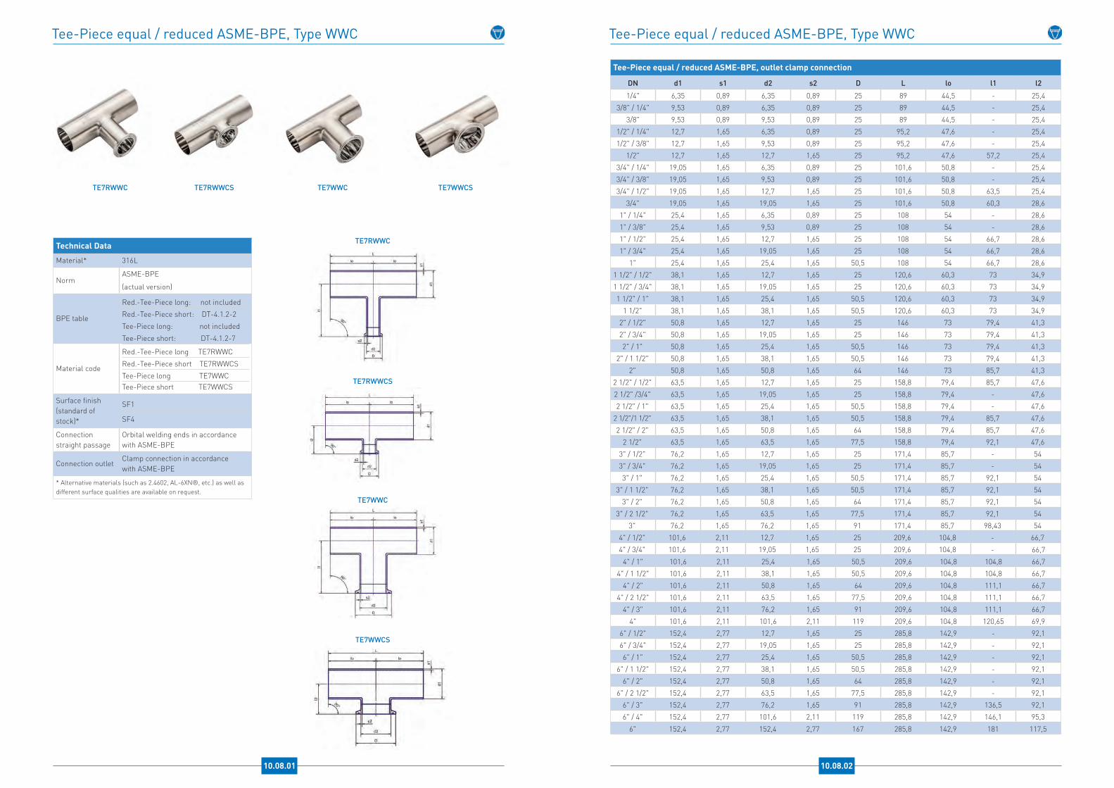
Tee-Piece equal / reduced ASME-BPE, Type WWC
10.08.01
Technical Data
Material* 316L
NormASME-BPE
(actual version)
BPE table
Red.-Tee-Piece long: not included
Red.-Tee-Piece short: DT-4.1.2-2
Tee-Piece long: not included
Tee-Piece short: DT-4.1.2-7
Material code
Red.-Tee-Piece long TE7RWWC
Red.-Tee-Piece short TE7RWWCS
Tee-Piece long TE7WWCTee-Piece short TE7WWCS
Surface finish (standard of stock)*
SF1
SF4
Connection straight passage
Orbital welding ends in accordance with ASME-BPE
Connection outletClamp connection in accordance with ASME-BPE
* Alternative materials (such as 2.4602, AL-6XN®, etc.) as well as different surface qualities are available on request.
TE7RWWC TE7RWWCS TE7WWC TE7WWCS
TE7RWWC
TE7RWWCS
TE7WWC
TE7WWCS
Tee-Piece equal / reduced ASME-BPE, Type WWC
Tee-Piece equal / reduced ASME-BPE, outlet clamp connection
DN d1 s1 d2 s2 D L lo l1 l2
1/4" 6,35 0,89 6,35 0,89 25 89 44,5 - 25,43/8" / 1/4" 9,53 0,89 6,35 0,89 25 89 44,5 - 25,4
3/8" 9,53 0,89 9,53 0,89 25 89 44,5 - 25,41/2" / 1/4" 12,7 1,65 6,35 0,89 25 95,2 47,6 - 25,41/2" / 3/8" 12,7 1,65 9,53 0,89 25 95,2 47,6 - 25,4
1/2" 12,7 1,65 12,7 1,65 25 95,2 47,6 57,2 25,43/4" / 1/4" 19,05 1,65 6,35 0,89 25 101,6 50,8 - 25,43/4" / 3/8" 19,05 1,65 9,53 0,89 25 101,6 50,8 - 25,43/4" / 1/2" 19,05 1,65 12,7 1,65 25 101,6 50,8 63,5 25,4
3/4" 19,05 1,65 19,05 1,65 25 101,6 50,8 60,3 28,61" / 1/4" 25,4 1,65 6,35 0,89 25 108 54 - 28,61" / 3/8" 25,4 1,65 9,53 0,89 25 108 54 - 28,61" / 1/2" 25,4 1,65 12,7 1,65 25 108 54 66,7 28,61" / 3/4" 25,4 1,65 19,05 1,65 25 108 54 66,7 28,6
1" 25,4 1,65 25,4 1,65 50,5 108 54 66,7 28,61 1/2" / 1/2" 38,1 1,65 12,7 1,65 25 120,6 60,3 73 34,91 1/2" / 3/4" 38,1 1,65 19,05 1,65 25 120,6 60,3 73 34,91 1/2" / 1" 38,1 1,65 25,4 1,65 50,5 120,6 60,3 73 34,9
1 1/2" 38,1 1,65 38,1 1,65 50,5 120,6 60,3 73 34,92" / 1/2" 50,8 1,65 12,7 1,65 25 146 73 79,4 41,32" / 3/4" 50,8 1,65 19,05 1,65 25 146 73 79,4 41,32" / 1" 50,8 1,65 25,4 1,65 50,5 146 73 79,4 41,3
2" / 1 1/2" 50,8 1,65 38,1 1,65 50,5 146 73 79,4 41,32" 50,8 1,65 50,8 1,65 64 146 73 85,7 41,3
2 1/2" / 1/2" 63,5 1,65 12,7 1,65 25 158,8 79,4 85,7 47,62 1/2" /3/4" 63,5 1,65 19,05 1,65 25 158,8 79,4 - 47,62 1/2" / 1" 63,5 1,65 25,4 1,65 50,5 158,8 79,4 - 47,6
2 1/2"/1 1/2" 63,5 1,65 38,1 1,65 50,5 158,8 79,4 85,7 47,62 1/2" / 2" 63,5 1,65 50,8 1,65 64 158,8 79,4 85,7 47,6
2 1/2" 63,5 1,65 63,5 1,65 77,5 158,8 79,4 92,1 47,63" / 1/2" 76,2 1,65 12,7 1,65 25 171,4 85,7 - 543" / 3/4" 76,2 1,65 19,05 1,65 25 171,4 85,7 - 543" / 1" 76,2 1,65 25,4 1,65 50,5 171,4 85,7 92,1 54
3" / 1 1/2" 76,2 1,65 38,1 1,65 50,5 171,4 85,7 92,1 543" / 2" 76,2 1,65 50,8 1,65 64 171,4 85,7 92,1 54
3" / 2 1/2" 76,2 1,65 63,5 1,65 77,5 171,4 85,7 92,1 543" 76,2 1,65 76,2 1,65 91 171,4 85,7 98,43 54
4" / 1/2" 101,6 2,11 12,7 1,65 25 209,6 104,8 - 66,74" / 3/4" 101,6 2,11 19,05 1,65 25 209,6 104,8 - 66,7
4" / 1" 101,6 2,11 25,4 1,65 50,5 209,6 104,8 104,8 66,74" / 1 1/2" 101,6 2,11 38,1 1,65 50,5 209,6 104,8 104,8 66,7
4" / 2" 101,6 2,11 50,8 1,65 64 209,6 104,8 111,1 66,74" / 2 1/2" 101,6 2,11 63,5 1,65 77,5 209,6 104,8 111,1 66,7
4" / 3" 101,6 2,11 76,2 1,65 91 209,6 104,8 111,1 66,74" 101,6 2,11 101,6 2,11 119 209,6 104,8 120,65 69,9
6" / 1/2" 152,4 2,77 12,7 1,65 25 285,8 142,9 - 92,16" / 3/4" 152,4 2,77 19,05 1,65 25 285,8 142,9 - 92,16" / 1" 152,4 2,77 25,4 1,65 50,5 285,8 142,9 - 92,1
6" / 1 1/2" 152,4 2,77 38,1 1,65 50,5 285,8 142,9 - 92,16" / 2" 152,4 2,77 50,8 1,65 64 285,8 142,9 - 92,1
6" / 2 1/2" 152,4 2,77 63,5 1,65 77,5 285,8 142,9 - 92,16" / 3" 152,4 2,77 76,2 1,65 91 285,8 142,9 136,5 92,16" / 4" 152,4 2,77 101,6 2,11 119 285,8 142,9 146,1 95,3
6" 152,4 2,77 152,4 2,77 167 285,8 142,9 181 117,5
10.08.02
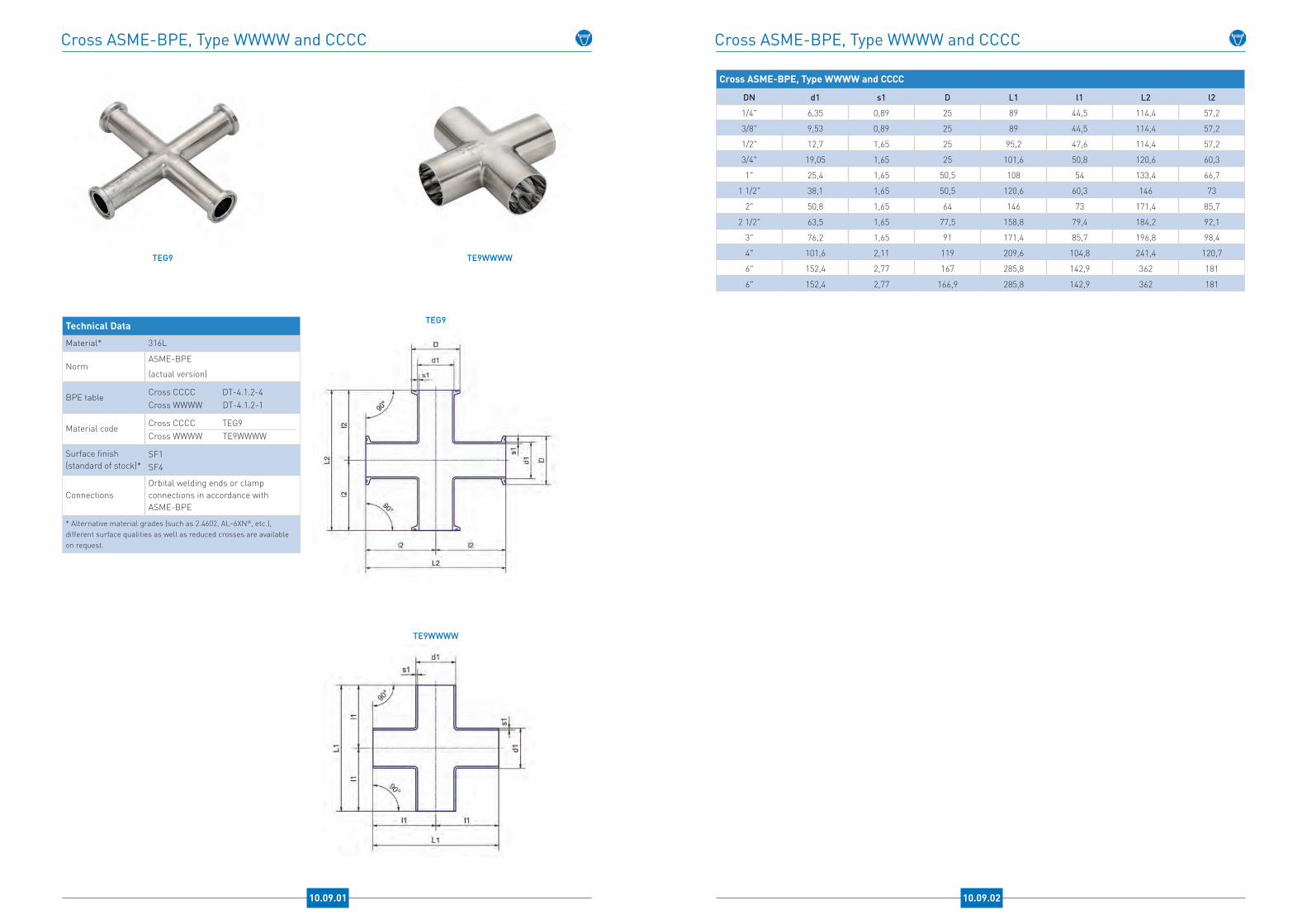
Cross ASME-BPE, Type WWWW and CCCC
10.09.01
Technical Data
Material* 316L
NormASME-BPE
(actual version)
BPE table Cross CCCC DT-4.1.2-4Cross WWWW DT-4.1.2-1
Material code Cross CCCC TEG9Cross WWWW TE9WWWW
Surface finish(standard of stock)*
SF1SF4
ConnectionsOrbital welding ends or clamp connections in accordance with ASME-BPE
* Alternative material grades (such as 2.4602, AL-6XN®, etc.), different surface qualities as well as reduced crosses are available on request.
TEG9 TE9WWWW
TE9WWWW
TEG9
Cross ASME-BPE, Type WWWW and CCCC
Cross ASME-BPE, Type WWWW and CCCC
DN d1 s1 D L1 l1 L2 l2
1/4" 6,35 0,89 25 89 44,5 114,4 57,2
3/8" 9,53 0,89 25 89 44,5 114,4 57,2
1/2" 12,7 1,65 25 95,2 47,6 114,4 57,2
3/4" 19,05 1,65 25 101,6 50,8 120,6 60,3
1" 25,4 1,65 50,5 108 54 133,4 66,7
1 1/2" 38,1 1,65 50,5 120,6 60,3 146 73
2" 50,8 1,65 64 146 73 171,4 85,7
2 1/2" 63,5 1,65 77,5 158,8 79,4 184,2 92,1
3" 76,2 1,65 91 171,4 85,7 196,8 98,4
4" 101,6 2,11 119 209,6 104,8 241,4 120,7
6" 152,4 2,77 167 285,8 142,9 362 181
6" 152,4 2,77 166,9 285,8 142,9 362 181
10.09.02

Concentric Reducers ASME-BPE, Type WW, CW, CC
10.10.01
Technical Data
Material* 316L
NormASME-BPE
(actual version)
BPE tableWW DT-4.1.3-1
CC DT-4.1.3-3
CW DT-4.1.3-2
Material code
WW TE31SWW
CC TEG31SCC
CW TEG31SCW
Surface finish(standard of stock)*
SF1
SF4
* Alternative material grades (such as 2.4602, AL-6XN®, etc.) as well as different surface qualities are available on request.
TE31SWW
TE31SWW
TEG31SCC
TE31SCW
TEG31SCC TE31SCW
Concentric Reducers ASME-BPE, Type WW, CW, CC
Concentric Reducers ASME-BPE, Type WW, CW and CC
DN d1 s1 D1 d2 s2 D2 L1 l1 l2 L2 L3
3/8" / 1/4" 9,53 0,89 25 6,35 0,89 25 41,28 19,05 19,05 53,78 66,675
1/2" / 1/4" 12,7 1,65 25 6,35 0,89 25 47,63 25,4 19,05 60,33 73,025
1/2" / 3/8" 12,7 1,65 25 9,53 0,89 25 47,63 25,4 19,05 60,33 73,025
3/4" / 3/8" 19,05 1,65 25 9,53 0,89 25 50,8 25,4 19,05 63,5 76,2
3/4" / 1/2" 19,05 1,65 25 12,7 1,65 25 53,98 25,4 25,4 66,68 79,375
1" / 1/2" 25,4 1,65 50,5 12,7 1,65 25 63,5 25,4 25,4 76,2 88,9
1" / 3/4" 25,4 1,65 50,5 19,05 1,65 25 53,98 25,4 25,4 66,68 79,375
1 1/2" / 3/4" 38,1 1,65 50,5 19,05 1,65 25 76,2 25,4 25,4 88,9 101,6
1 1/2" / 1" 38,1 1,65 50,5 25,4 1,65 50,5 63,5 25,4 25,4 76,2 88,9
2" / 1" 50,8 1,65 64 25,4 1,65 50,5 85,73 25,4 25,4 98,43 111,125
2" / 1 1/2" 50,8 1,65 64 38,1 1,65 50,5 63,5 25,4 25,4 76,2 88,9
2 1/2" / 1 1/2" 63,5 1,65 77,5 38,1 1,65 50,5 85,73 25,4 25,4 98,43 111,125
2 1/2" / 2" 63,5 1,65 77,5 50,8 1,65 64 63,5 25,4 25,4 76,2 88,9
3" / 1 1/2" 76,2 1,65 91 38,1 1,65 50,5 107,95 38,1 25,4 120,65 133,35
3" / 2" 76,2 1,65 91 50,8 1,65 64 85,73 38,1 25,4 98,43 111,125
3" / 2 1/2" 76,2 1,65 91 63,5 1,65 77,5 66,68 38,1 25,4 79,38 92,075
4" / 2" 101,6 2,11 119 50,8 1,65 64 130,18 38,1 25,4 146,05 158,75
4" / 2 1/2" 101,6 2,11 119 63,5 1,65 77,5 107,95 38,1 25,4 123,83 136,525
4" / 3" 101,6 2,11 119 76,2 1,65 91 98,43 38,1 38,1 114,3 127
6" / 3" 152,4 2,77 167 76,2 1,65 91 184,15 50,8 38,1 203,2 215,9
6" / 4" 152,4 2,77 167 101,6 2,11 119 142,88 50,8 38,1 161,93 177,8
4" / 2 1/2" 101,6 2,11 119 63,5 1,65 77,5 107,95 38,1 25,4 123,83 136,525
4" / 3" 101,6 2,11 119 76,2 1,65 91 98,43 38,1 38,1 114,3 127
6" / 3" 152,4 2,77 167 76,2 1,65 91 184,15 50,8 38,1 203,2 215,9
6" / 4" 152,4 2,77 167 101,6 2,11 119 142,88 50,8 38,1 161,93 177,8
10.10.02

Eccentric Reducers ASME-BPE, Type WW, CW, CC
10.11.01
Technical Data
Material* 316L
NormASME-BPE
(actual version)
BPE tableWW DT-4.1.3-1
CC DT-4.1.3-3CW DT-4.1.3-2
Material code
WW TE32SWW
CC TE32SCC
CW TEG32SCW
Surface finish(standard of stock)*
SF1
SF4
* Alternative material grades (such as 2.4602, AL-6XN®, etc.) as well as different surface qualities are available on request.
TE32SWW
TE32SWW
TEG32SCC
TE32SCW
TEG32SCC TE32SCW
Eccentric Reducers ASME-BPE, Type WW, CW, CC
Eccentric Reducers ASME-BPE, Type WW, CW and CC
DN d1 s1 D1 d2 s2 D2 L1 l1 l2 L2 L3
3/8" / 1/4" 9,53 0,89 25 6,35 0,89 25 41,28 19,05 19,05 53,78 66,68
1/2" / 1/4" 12,7 1,65 25 6,35 0,89 25 47,63 25,4 19,05 60,33 73,03
1/2" / 3/8" 12,7 1,65 25 9,53 0,89 25 47,63 25,4 19,05 60,33 73,03
3/4" / 3/8" 19,05 1,65 25 9,53 0,89 25 50,8 25,4 19,05 63,5 76,2
3/4" / 1/2" 19,05 1,65 25 12,7 1,65 25 53,98 25,4 25,4 66,68 79,38
1" / 1/2" 25,4 1,65 50,5 12,7 1,65 25 63,5 25,4 25,4 76,2 88,9
1" / 3/4" 25,4 1,65 50,5 19,05 1,65 25 53,98 25,4 25,4 66,68 79,38
1 1/2" / 3/4" 38,1 1,65 50,5 19,05 1,65 25 76,2 25,4 25,4 88,9 101,6
1 1/2" / 1" 38,1 1,65 50,5 25,4 1,65 50,5 63,5 25,4 25,4 76,2 88,9
2" / 1" 50,8 1,65 64 25,4 1,65 50,5 85,73 25,4 25,4 98,43 111,13
2" / 1 1/2" 50,8 1,65 64 38,1 1,65 50,5 63,5 25,4 25,4 76,2 88,9
2 1/2" / 1 1/2" 63,5 1,65 77,5 38,1 1,65 50,5 85,73 25,4 25,4 98,43 111,13
2 1/2" / 2" 63,5 1,65 77,5 50,8 1,65 64 63,5 25,4 25,4 76,2 88,9
3" / 1 1/2" 76,2 1,65 91 38,1 1,65 50,5 107,95 38,1 25,4 120,65 133,35
3" / 2" 76,2 1,65 91 50,8 1,65 64 85,73 38,1 25,4 98,43 111,13
3" / 2 1/2" 76,2 1,65 91 63,5 1,65 77,5 66,68 38,1 25,4 79,38 92,08
4" / 2" 101,6 2,11 119 50,8 1,65 64 130,18 38,1 25,4 146,05 158,75
4" / 2 1/2" 101,6 2,11 119 63,5 1,65 77,5 107,95 38,1 25,4 123,83 136,53
4" / 3" 101,6 2,11 119 76,2 1,65 91 98,43 38,1 38,1 114,3 127
6" / 3" 152,4 2,77 167 76,2 1,65 91 184,15 50,8 38,1 203,2 215,9
6" / 4" 152,4 2,77 167 101,6 2,11 119 142,88 50,8 38,1 161,93 177,8
4" / 2 1/2" 101,6 2,11 119 63,5 1,65 77,5 107,95 38,1 25,4 123,83 136,525
4" / 3" 101,6 2,11 119 76,2 1,65 91 98,43 38,1 38,1 114,3 127
6" / 3" 152,4 2,77 167 76,2 1,65 91 184,15 50,8 38,1 203,2 215,9
6" / 4" 152,4 2,77 167 101,6 2,11 119 142,88 50,8 38,1 161,93 177,8
10.11.02
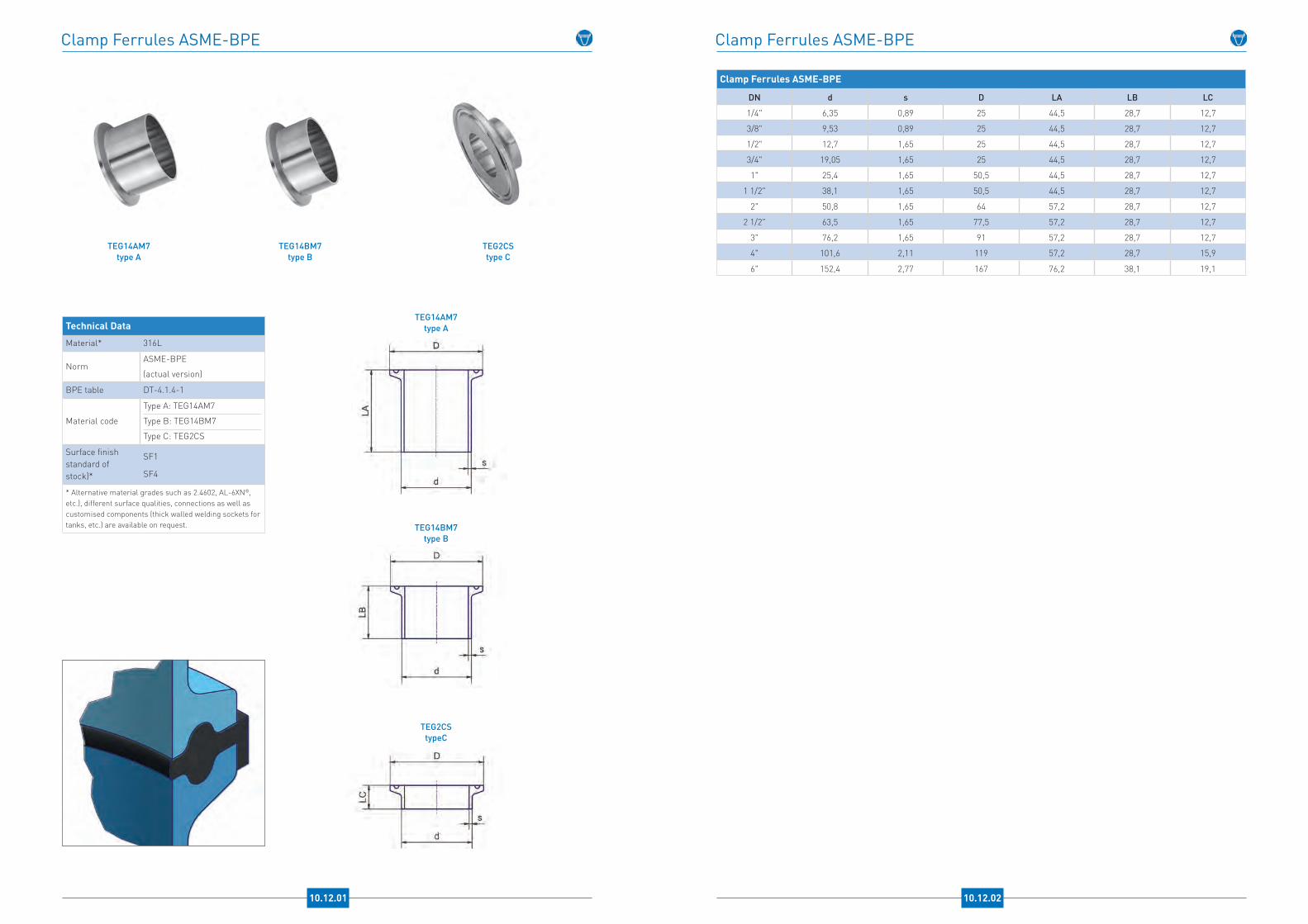
Clamp Ferrules ASME-BPE
10.12.01
Technical Data
Material* 316L
NormASME-BPE
(actual version)
BPE table DT-4.1.4-1
Material code
Type A: TEG14AM7
Type B: TEG14BM7
Type C: TEG2CS
Surface finish standard of stock)*
SF1
SF4
* Alternative material grades such as 2.4602, AL-6XN®, etc.), different surface qualities, connections as well as customised components (thick walled welding sockets for tanks, etc.) are available on request.
TEG14BM7type B
TEG14AM7type A
TEG2CStype C
TEG14AM7type A
TEG14BM7type B
TEG2CStypeC
Clamp Ferrules ASME-BPE
Clamp Ferrules ASME-BPE
DN d s D LA LB LC
1/4" 6,35 0,89 25 44,5 28,7 12,7
3/8" 9,53 0,89 25 44,5 28,7 12,7
1/2" 12,7 1,65 25 44,5 28,7 12,7
3/4" 19,05 1,65 25 44,5 28,7 12,7
1" 25,4 1,65 50,5 44,5 28,7 12,7
1 1/2" 38,1 1,65 50,5 44,5 28,7 12,7
2" 50,8 1,65 64 57,2 28,7 12,7
2 1/2" 63,5 1,65 77,5 57,2 28,7 12,7
3" 76,2 1,65 91 57,2 28,7 12,7
4" 101,6 2,11 119 57,2 28,7 15,9
6" 152,4 2,77 167 76,2 38,1 19,1
10.12.02
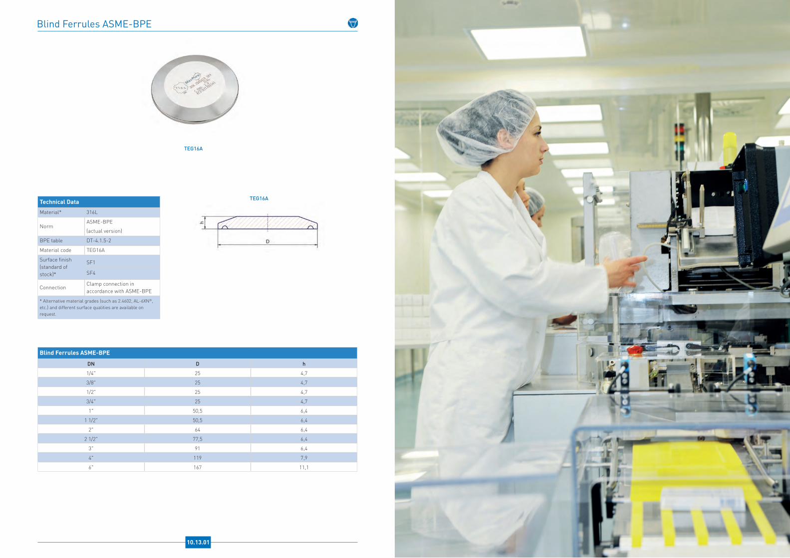
Blind Ferrules ASME-BPE
10.13.01
Technical Data
Material* 316L
NormASME-BPE
(actual version)
BPE table DT-4.1.5-2
Material code TEG16A
Surface finish (standard of stock)*
SF1
SF4
ConnectionClamp connection in accordance with ASME-BPE
* Alternative material grades (such as 2.4602, AL-6XN®, etc.) and different surface qualities are available on request.
TEG16A
TEG16A
Blind Ferrules ASME-BPE
DN D h
1/4" 25 4,7
3/8" 25 4,7
1/2" 25 4,7
3/4" 25 4,7
1" 50,5 6,4
1 1/2" 50,5 6,4
2" 64 6,4
2 1/2" 77,5 6,4
3" 91 6,4
4" 119 7,9
6" 167 11,1
Male / Female Adapter, Clamp Connection ASME-BPE / NPT Thread
10.14.01
Technical Data
Material* 316L
Material code
Male adapter (external thread): TEG21 Female adapter (internal thread): TEG22
Surface finish (standard of stock)*
SF1SF4
Connections
Clamp connection in accordance with ASME-BPEinternal / external thread NPT
Spanner flat Depending on dimension
* Alternative material grades (such as 2.4602, AL-6XN®, etc.) as well as different surface qualities and connections are available on request.
Female AdapterTEG22
Male AdapterTEG21
TEG22
TEG21
Male / Female Adapter, Clamp Connection ASME-BPE / NPT Thread
Adapter, Clamp Connection ASME-BPE / NPT Thread
DN A
1/2" / 1/8" 50,8
1/2" / 1/4" 50,8
1/2" / 3/8" 50,8
1/2" / 1/2" 50,8
1/2" / 3/4" 50,8
3/4" / 1/8" 50,8
3/4" / 1/4" 50,8
3/4" / 3/8" 50,8
3/4" / 1/2" 50,8
3/4" / 3/4" 50,8
1" 57,1
1 1/2" 61,9
2" 67,5
2 1/2" 83,3
3" 88,9
4" 96,7
10.14.02

Tube End Cap ASME-BPE
10.15.01
Technical Data
Material* 316L
NormASME-BPE
(actual version)
BPE table DT-4.1.5-1
Material code TE16W
Surface finish (standard of stock)*
SF1
SF4
ConnectionOrbital welding end in accordance with ASME-BPE
* Alternative material grades (such as 2.4602, AL-6XN®, etc.) as well as different surface qualities and weld ends are available on request.
TE16W
TE16W
Tube End Cap ASME-BPE
DN d s L
1/4" 6,35 0,89 38,1
3/8" 9,53 0,89 38,1
1/2" 12,7 1,65 38,1
3/4" 19,05 1,65 38,1
1" 25,4 1,65 38,1
1 1/2" 38,1 1,65 38,1
2" 50,8 1,65 38,1
2 1/2" 63,5 1,65 38,1
3" 76,2 1,65 44,5
4" 101,6 2,11 50,8
6" 152,4 2,77 63,5
11.01.01
Table of Materials
EN TypeC ≤ %
Cr %
Ni %
Mo %
Si ≤%
Mn ≤ %
S ≤ %
P ≤ %
otherComparable
material AISI
Comparable material
SS
1.4301
austenite
0,07 17,5-19,58,0-10,5
- 1,0 2,0 0,015 0,045 N ≤ 0,11 304 2333
1.4306 0,03 18,0-20,0 10,0-12,0 - 1,0 2,0 0,015 0,045 N ≤ 0,11 304L 2352
1.4307 0,03 17,5-19,5 8,0-10,5 - 1,0 2,0 0,015 0,045 N ≤ 0,11 304L -
1.4541 0,08 17,0-19,0 9,0-12,0 - 1,0 2,0 0,015 0,045 Ti (5xC)-0,70 321 2337
1.4401
austenite(acid-
resistant)
0,07 16,5-18,5 10,0-13,0 2,0-2,5 1,0 2,0 0,015 0,045 N ≤ 0,11 316 2347
1.4404 0,03 16,5-18,5 10,0-13,0 2,0-2,5 1,0 2,0 0,015 0,045 N ≤ 0,11 316L 2348
1.4432 0,03 16,5-18,5 10,5-13,0 2,5-3,0 1,0 2,0 0,015 0,045 N ≤ 0,11 316L 2353
1.4435 0,03 17,0-19,0 12,5-15,0 2,5-3,0 1,0 2,0 0,015 0,045 N ≤ 0,11 316L 2353
1.4539 0,02 19,0-21,0 24,0-26,0 4,0-5,0 0,7 2,0 0,015 0,030 N ≤ 0,15; Cu 1,20-2,00 904L 2562
1.4571 0,08 16,5-18,5 10,5-13,5 2,0-2,5 1,0 2,0 0,015 0,045 Ti (5xC)-0,70 316Ti 2350
1.4529 Super-austenite(6-Moly)
0,02 20,0-21,0 24,5-25,5 6,0-6,8 0,5 1,0 0,005 0,030N 0,18-0,2%, Cu 0,8-
1,0%AL-6XN® -
1.4547 0,02 19,5-20,5 17,5-18,5 6,0-7,0 0,7 1,0 0,010 0,030N 0,18-0,25%, Cu 0,5-
1,0%UNS S 31254
254 SMO
1.4462 Duplex 0,03 21,0-23,0 4,5-6,5 2,5-3,5 1,0 2,0 0,015 0,035 N 0,10-0,22 UNS S 31803 2377
1.4501Super-duplex
0,03 24,0-26,0 6,0-8,0 3,0-4,0 1,0 1,0 0,015 0,035N 0,20-0,30%, Cu 0,5-
1,0%, W 2,5-3,5%UNS S 32760 -
1.4410 0,03 24,0-26,0 6,0-8,0 3,5-5,0 1,0 1,0 0,015 0,035 N 0,24-0,32% UNS S 32750 -
2.4602
nickel-base alloy
0,01 20,0-22,5Rest ( ca.
60%)12,5-14,5 0,08 0,5 0,010 0,025
Fe 2-6%,W 2,5-3,5%, Co ≤ 2,5%
HastelloyC-22
-
2.4605 0,01 22,0-24,0Rest ( ca.
60%)15,0-16,0 0,1 0,5 0,015 0,025
Fe ≤ 1,5%, Cu ≤ 0,5%, Co ≤ 0,3%
Alloy 59 -
2.4610 0,009 14,5-17,5Rest ( ca.
65%)14,0-17,0 0,05 1,0 0,010 0,020
Fe ≤ 3,0%, Ti ≤ 0,7%, Co ≤ 2,0%
HastelloyC4
-
2.4819 0,01 14,5-16,5Rest ( ca.
58%)15,0-17,0 0,08 1,0 0,010 0,025
Fe 4-7%,W 3,0-4,5%, Co ≤ 2,5%
HastelloyC-276
-
All information supplied without warranty

NEUMO Aseptic Heat ExchangersCalculated and designed individually - perfectly matching your process
Concerning pharmaceutical and biotechnolo-gical plants as well as ultra-pure water production, heat exchangers are one of the most critical, quality-relevant unit operations.
NEUMO tube-bundle heat exchangers with double tubesheet and orbitally welded primary pipes offer maximum process security. In addition to the standard materials we are experts in the processing of special materials for every special application.
National and international certifications enable worldwide use of our heat exchangers.
12.01.01
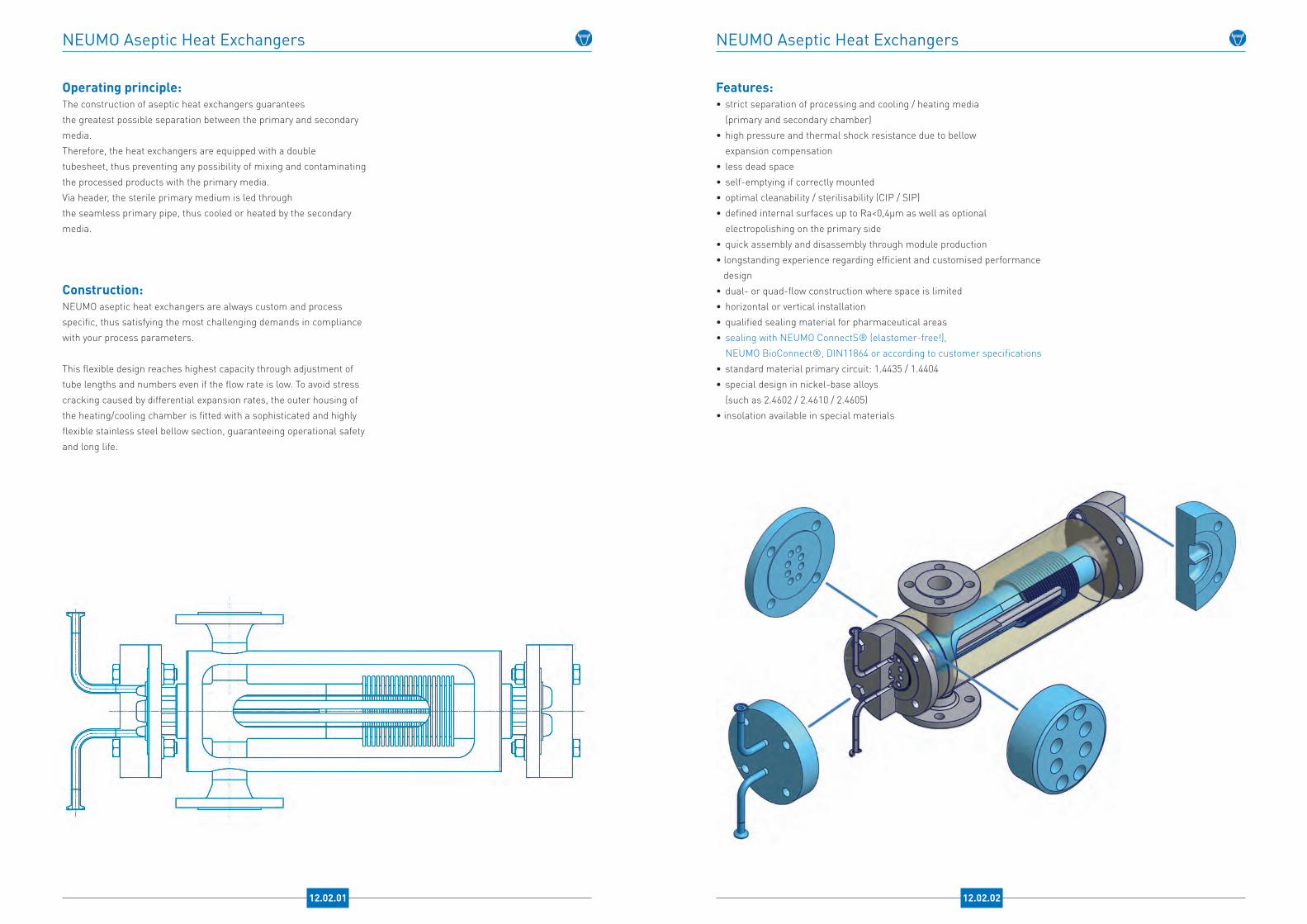
NEUMO Aseptic Heat Exchangers
Operating principle:The construction of aseptic heat exchangers guaranteesthe greatest possible separation between the primary and secondary media.Therefore, the heat exchangers are equipped with a double tubesheet, thus preventing any possibility of mixing and contaminating the processed products with the primary media. Via header, the sterile primary medium is led throughthe seamless primary pipe, thus cooled or heated by the secondary media.
Construction:NEUMO aseptic heat exchangers are always custom and process specific, thus satisfying the most challenging demands in compliance with your process parameters.
This flexible design reaches highest capacity through adjustment of tube lengths and numbers even if the flow rate is low. To avoid stress cracking caused by differential expansion rates, the outer housing of the heating/cooling chamber is fitted with a sophisticated and highly flexible stainless steel bellow section, guaranteeing operational safety and long life.
NEUMO Aseptic Heat Exchangers
Features:• strict separation of processing and cooling / heating media (primary and secondary chamber)• high pressure and thermal shock resistance due to bellow expansion compensation• less dead space• self-emptying if correctly mounted• optimal cleanability / sterilisability (CIP / SIP) • defined internal surfaces up to Ra<0,4µm as well as optional electropolishing on the primary side • quick assembly and disassembly through module production• longstanding experience regarding efficient and customised performance design• dual- or quad-flow construction where space is limited • horizontal or vertical installation• qualified sealing material for pharmaceutical areas • sealing with NEUMO ConnectS® (elastomer-free!), NEUMO BioConnect®, DIN11864 or according to customer specifications• standard material primary circuit: 1.4435 / 1.4404• special design in nickel-base alloys (such as 2.4602 / 2.4610 / 2.4605)• insolation available in special materials
12.02.02 12.02.01
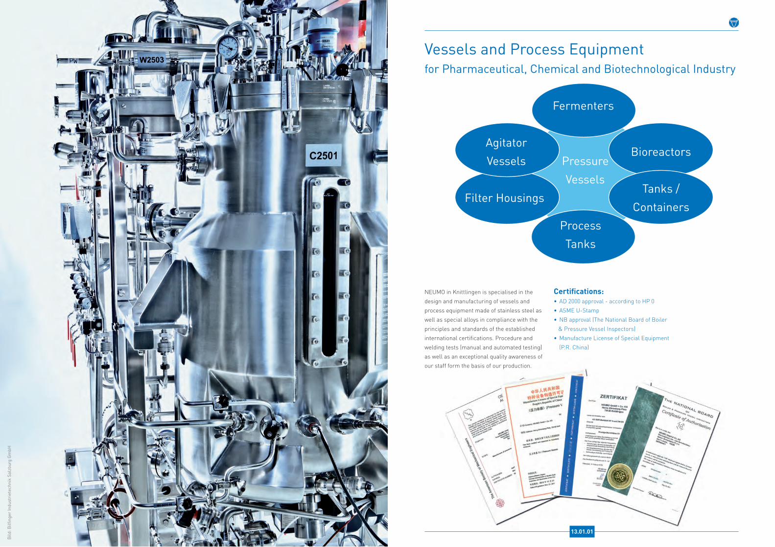
Bild
: Bilfi
nger
Indu
stri
etec
hnik
Sal
zbur
g G
mbH
Vessels and Process Equipment for Pharmaceutical, Chemical and Biotechnological Industry
Pressure Vessels
Fermenters
ProcessTanks
Bioreactors
Tanks /Containers
Filter Housings
Agitator Vessels
NEUMO in Knittlingen is specialised in the design and manufacturing of vessels and process equipment made of stainless steel as well as special alloys in compliance with the principles and standards of the established international certifications. Procedure and welding tests (manual and automated testing) as well as an exceptional quality awareness of our staff form the basis of our production.
Certifications:• AD 2000 approval - according to HP 0• ASME U-Stamp• NB approval (The National Board of Boiler & Pressure Vessel Inspectors)• Manufacture License of Special Equipment (P.R. China)
13.01.01

Vessels and Process Equipment
Application Industries:• Pharmaceutical industry• Biotechnology• Chemical industry• Food processing• Water processing
Sizes:• 0,5 - 3.000 litres• up to 20 tons unit weight• up to 100 bar operating pressure
Material grades:• 1.4301 / 304L• 1.4404 / 316L• 1.4571 / 316Ti• 1.4435• 1.4539 (904L)• 1.4462 (Duplex)• 2.4602 (Hastelloy C-22)• 2.4605 (Alloy 59)• 2.4610 (Hastelloy C-4)• 2.4819 (Hastelloy C-276)• further materials on request
Surface finishes:• pickled / passivated• polished (mech.) up to Ra<0,2μm• mirror finishing (mech.)• electropolished• glass beaded
Process Connections / Vessel Sealing:• clamp- and flange connections according to the established norms• NEUMO ConnectS® (process connections and vessel sealing without elastomer) • NEUMO BioConnect®
• NEUMO BioControl®
With NEUMO ConnectS® and NEUMO BioControl® CS we offer an innovative completely elastomer-free alternative for the sealing and inclusion of measuring and analysing instruments. The metallic seal contour is directly turned into the cover, or a BioControl® CS block flange (see chapter BioControl®- block flanges) is welded into the vessel to include instruments.
NEUMO BioControl® CS
NEUMO ConnectS®
Vessels and Process Equipment
Heating or Cooling:• double jacket• pillow plates• tube coil (rectangular or oder half-piped)
Insolation and Casing:• mineral wool• mineral wool free of chloride• perlite• diffusion-proof welding, stainless steel
Design:• freestanding (3-podal / 4-podal / 5-podal)• height-adjustable• horizontal on saddles• with claws• with lid-lifting device (electrical / mechanical / hydraulical)• movable frame
Construction:• with Inventor 3D• fabricated according to required certifications
We will be pleased to advise you on the planning, dimensioning and de-sign of your process vessel as well as on optimising the interfaces to manufacture your vessels tailored to your needs. We use Inventor 3D for the design and provide you with the 3D-model, thus facilitating your planning.
13.02.02 13.02.01

High-performance Materials and Custom Design
Over many years NEUMO has increasingly specialised in special materials and special design. Today we dominate the market as a competent reference and warehouse keeper for special alloys. Furthermore we are a supplier of high quality special design.
The product range includes the production of components fabricated to drawing as well as tubes and standardised fittings (for example DIN11865 and ASME-BPE) in special alloys.
In addition, we offer our patented products BioConnect®, ConnectS®, BioControl® and BioFlow check valves in special materials.
Our offered product portfolio is rounded off by our range of semi-finished products, such as sheets, bar steel and cuttings in standard or special materials.
14.01.01
Picture: Spool DN700 for chemical industry, manufactured by NEUMO.

High-performance Materials and Custom Design
Distribution Pipes
Customised Construction
Customised Connections
Customised Fittings
. . . designed and manufactured with support of your specialist engineers!
Reducer Elbows
High-performance Materials and Custom Design
1.4539/904L
AL-6XN ®
2.4602/C-22
2.4605/Alloy 59
2.4610/C-4
2.4819/C-276
1.4462
Titanium
...
• Tubes
• Fittings (standard + custom)
• Tube Connections (standard + custom)
• Customised Machined Items
• Prefabricated Spools
• Distribution Pipes
• Customised Constructions
• Vessels and Process Equipment
• Bar Steel
• Sheets
• Cuttings
• and many more ...
14.02.02 14.02.01
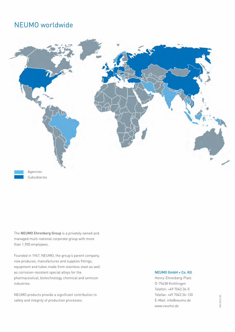
NEUMO GmbH + Co . KGHenry-Ehrenberg-PlatzD-75438 KnittlingenTelefon: +49 7043 36-0Telefax: +49 7043 36-130E-Mail: [email protected]
NEUMO worldwide
The NEUMO Ehrenberg Group is a privately owned and managed multi-national corporate group with more than 1.900 employees.
Founded in 1947, NEUMO, the group‘s parent company, now produces, manufactures and supplies fittings, equipment and tubes made from stainless steel as well as corrosion-resistent special alloys for the pharmaceutical, biotechnology, chemical and semiconindustries.
NEUMO products provide a significant contribution to safety and integrity of production processes.
AgenciesSubsidiaries
EN-2
016-
03