www.elsevier.com/locate/apsusc
Applied Surface Science 253 (2007) 5076–5083
Nanolayered multilayer coatings of CrN/CrAlN prepared
by reactive DC magnetron sputtering
Harish C. Barshilia a,*, B. Deepthi a, N. Selvakumar a, Anjana Jain b, K.S. Rajam a
a Surface Engineering Division, National Aerospace Laboratories, Post Bag No. 1779, Bangalore 560017, Indiab Materials Science Division, National Aerospace Laboratories, Bangalore 560017, India
Received 14 June 2006; received in revised form 9 November 2006; accepted 13 November 2006
Available online 8 December 2006
Abstract
Single-phase CrN and CrAlN coatings were deposited on silicon and mild steel substrates using a reactive DC magnetron sputtering system. The
structural characterization of the coatings was done using X-ray diffraction (XRD). The XRD data showed that both the CrN and CrAlN coatings
exhibited B1 NaCl structure with a prominent reflection along (2 0 0) plane. The bonding structure of the coatings was characterized by X-ray
photoelectron spectroscopy and the surface morphology of the coatings was studied using atomic force microscopy. Subsequently, nanolayered
CrN/CrAlN multilayer coatings with a total thickness of approximately 1 mm were deposited on silicon substrates at different modulation
wavelengths (L). The XRD data showed that all the multilayer coatings were textured along {2 0 0}. The CrN/CrAlN multilayer coatings exhibited
a maximum nanoindentation hardness of 3125 kg/mm2 at a modulation wavelength of 72 A, whereas single layer CrN and CrAlN deposited under
similar conditions exhibited hardness values of 2375 and 2800 kg/mm2, respectively. Structural changes as a result of heating of the multilayer
coatings in air (400–800 8C) were characterized using XRD and micro-Raman spectroscopy. The XRD data showed that the multilayer coatings
were stable up to a temperature of 650 8C and peaks pertaining to Cr2O3 started appearing at 700 8C. These results were confirmed by micro-Raman
spectroscopy. Nanoindentation measurements performed on the heat-treated coatings revealed that the multilayer coatings retained hardness as
high as 2250 kg/mm2 after annealing up to a temperature of 600 8C.
# 2006 Elsevier B.V. All rights reserved.
Keywords: CrN and CrAlN films; CrN/CrAlN nanolayered multilayers; Magnetron sputtering; Structural and mechanical properties; Thermal stability
1. Introduction
Thin films based on carbides and nitrides of transition metals
have been very successful in improving the performance of
cutting tools. Although TiN is the most widely used in
industrial applications, CrN has been gaining importance in
recent years due to its superior corrosion and wear resistances,
friction behavior and low internal stress [1–3]. However, there
are an increasing number of applications where properties of
single layer coatings are not sufficient. Therefore, recent
research is focused on the development of nanolayered
multilayer coatings in order to meet the requirements in terms
of hardness, thermal stability, coefficient of friction, corrosion
resistance and internal stress [4–11]. Nanolayered multilayer
* Corresponding author. Tel.: +91 80 2508 6494; fax: +91 80 2521 0113.
E-mail address: [email protected] (H.C. Barshilia).
0169-4332/$ – see front matter # 2006 Elsevier B.V. All rights reserved.
doi:10.1016/j.apsusc.2006.11.021
coatings are composed of two different alternating layers with
nanometer scale dimensions. These nanostructured multilayer
coatings are also called superlattices. The thickness of each
successive pair of layers is called modulation wavelength or
bilayer thickness (L), and it greatly affects the properties of the
multilayer coatings. The bilayers of the multilayers can be
metals, carbides, nitrides or oxides of different materials or a
combination of one layer made of nitride, carbide or oxide of
one metal and the second layer made of another metal.
A variety of multilayer systems such as TiN/CrN [4,5],
TiAlN/CrN [6,7], TiN/NbN [8–11], etc., have been studied
extensively. However, there are very few reports on the
multilayer coatings based on CrN and CrAlN [12]. CrN films
have been used for cutting tools, molding dies and machine
parts. But the oxidation resistance of CrN is limited up to
600 8C [13]. For hard protective coatings, thermal stability is
important as they are exposed to high temperatures during the
cutting process. The addition of Al to CrN raises the

Fig. 1. Typical cross section of a CrN coating.
Table 1
Summary of the deposition parameters
Target to substrate distance (cm) 5.4
Cr and CrAl targets diameter (cm) 7.5
Initial vacuum (Pa) 2.0 � 10�4
Working pressure (Pa) 4.0 � 10�1
Nitrogen flow rate (sccm) 3.5
Argon flow rate (sccm) 17
Power density to the Cr target (W/cm2) 2.20
Power density to the Cr–Al target (W/cm2) 2.20
Substrate bias (V) �200
Ion current density on CrN film (mA/cm2) 3.13
Ion current density on CrAlN film (mA/cm2) 3.8
Growth rate for CrN (m/h) 1.2
Growth rate for CrAlN (m/h) 0.8
Substrate temperature (8C) 300
Total thickness of the coating (mm) 1
H.C. Barshilia et al. / Applied Surface Science 253 (2007) 5076–5083 5077
temperature at which onset of oxidation occurs [14]. CrAlN
coatings have been reported to be stable up to a temperature of
900 8C depending upon the Al content in the coatings [15].
CrAlN coatings also exhibit higher hardness and a lower
friction co-efficient when compared to CrN coatings [16,17].
Even though CrAlN coatings have not been able to replace the
harder TiAlN coatings in tool coating applications, it is still an
alternative for some component applications due to its good
corrosion protection properties [18]. The addition of a third
element in the transition metal nitride coating generally
increases the residual stress [19]. Therefore, the CrAlN
coatings are expected to have higher residual stresses than
CrN coatings. High internal stress critically affects the adhesion
of the coatings, due to which thick coatings of CrAlN cannot be
obtained. These factors led to the exploration of the multilayer
coatings of CrN/CrAlN, wherein the properties of CrN and
CrAlN can be combined. In the present study, nanolayered
multilayer coatings of CrN/CrAlN have been deposited using
DC reactive magnetron sputtering. The structural and
mechanical properties have been studied using X-ray diffrac-
tion (XRD) and nanoindentation, respectively. The bonding
structure was characterized using X-ray photoelectron spectro-
scopy (XPS) and the surface morphology was studied using an
atomic force microscope (AFM). The structural changes as a
result of heating of the CrN/CrAlN multilayer coatings in air
were characterized using XRD and micro-Raman spectroscopy
to study their thermal stability.
2. Experimental details
Alternate layers of CrN and CrAlN of varying thicknesses
were deposited on silicon and steel substrates using a multi-
target reactive DC magnetron sputtering system that has been
described in detail elsewhere [20]. High purity Cr (99.95%)
CrAl (99.9%) targets were sputtered in high purity Ar
(99.999%) and N2 (99.999%) plasma. The composition of
CrAl target was approximately 50:50. In order to get varying
thicknesses of the CrN and CrAlN layers, the Cr and CrAl
targets were sputtered for different durations. The multilayer
coatings were deposited under a base pressure of 2.0 � 10�4 Pa
and a total Ar + N2 gas pressure of 4.0 � 10�1 Pa. The flow
rates of N2 and Ar were controlled separately by mass flow
controllers. The substrate to target distance was 5.4 cm. A DC
substrate bias of �200 V was applied to improve the
mechanical properties of the coatings. This resulted in ion
current densities of the order of 3.13 and 3.8 mA/cm2,
respectively, for CrN and CrAlN sputtered layers. The coatings
were deposited at a substrate temperature of 300 8C. For all the
experiments, the power density was approximately 2.20 W/cm2
for both Cr and CrAl targets. Under these conditions the growth
rates were approximately 3.5 A/s for CrN and approximately
2 A/s for CrAlN. The substrates were cleaned in an ultrasonic
agitator in acetone, isopropyl alcohol and trichloroethylene.
Subsequently, the substrates were cleaned in situ by Ar+ ion
bombardment for 45 min, wherein a DC bias of �850 V was
applied to the substrate at an argon pressure of 6.0 � 10�1 Pa.
Prior to the deposition, the targets were sputter cleaned for
5 min. A Cr interlayer of approximately 0.5 mm thickness was
deposited on the substrates for improved adhesion of the
coatings. The CrN and CrAlN layers had approximately equal
thickness. The total thickness of the coating was approximately
1 mm. The thickness of the coatings was determined from the
cross-section of the coating. Fig. 1 shows the typical cross-
section of a CrN coating deposited for 4 h. The coating
exhibited a thickness of approximately 4.6 mm, indicating a
growth rate of 1 mm/h. Multilayer coatings with controlled
layer thicknesses and repeatability were deposited using a PC-
based dwell time controller. In this system, a stepper motor was
connected to the substrate holder through a rotary feed-through.
The stepper motor was controlled by a driver circuit. The
process conditions used for the deposition of CrN/CrAlN
multilayer coatings are summarized in Table 1.
The XRD patterns of the coatings in Bragg–Brentano u–2u
geometry were recorded in a Rigaku D/max 2200 Ultima X-ray
powder diffractometer. The X-ray source was a Cu Ka radiation
(l = 0.15418 nm), which was operated at 40 kV and 40 mA.
The bonding structure of the coatings was characterized by XPS
using an ESCA 3000 (V. G. Microtech) system with a
monochromatic Al Ka X-ray beam (energy = 1486.5 eV and
power = 150 W). The mechanical properties (hardness and
elastic modulus) of the coatings were measured in a
H.C. Barshilia et al. / Applied Surface Science 253 (2007) 5076–50835078
nanoindenter (CSEM Instruments) at a load of 5 mN using a
Berkovich diamond indenter. At this load the indentation depth
was much less than 1/10th of the film thickness, thus
minimizing the effect of substrate on the hardness measure-
ments. Ten indentations were made on each sample and the
values reported herein represent the average of 10 values.
Surface imaging of the coatings was carried out using AFM.
The AFM (Surface Imaging Systems) was operated in non-
contact mode.
In order to test the thermal stability of the films, the CrN/
CrAlN multilayer coatings were heated in air in a resistive
furnace at TA = 400, 500, 550, 600, 650, 700, 750 and 800 8C.
Annealing involved increasing the temperature of the samples
from room temperature to the desired temperature at a slow
heating rate of 3 8C/min and maintaining the desired
temperature for 30 min. Subsequently, the samples were cooled
down at a rate of 3 8C/min. The structural changes as a result of
heating were measured using XRD and micro-Raman spectro-
scopy. A DILOR-JOBIN-YVON-SPEX integrated micro-
Raman spectrometer was used for the present study [21].
3. Results and discussion
3.1. Structural properties
The structure of CrN and CrAlN coatings depends strongly
on the nitrogen partial pressure and the substrate bias. The
stoichiometric phase of CrN with B1 NaCl structure exists in a
limited range of nitrogen concentration [22]. Therefore it
becomes necessary to first optimize the process parameters for
the deposition of cubic CrN and CrAlN phases. At a nitrogen
flow rate of less than 2.0 sccm, the XRD data of CrN coatings
showed a mixed structure of cubic (CrN) and hexagonal (b-
Cr2N) phases (results not shown). However, at higher flow rates
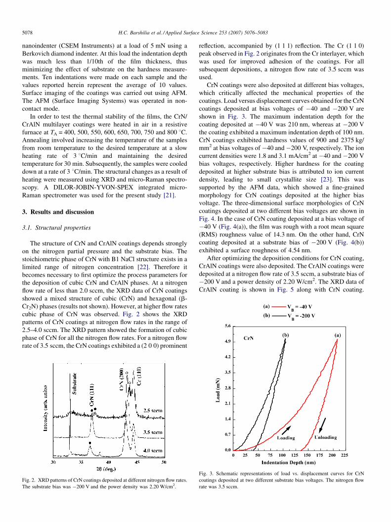
cubic phase of CrN was observed. Fig. 2 shows the XRD
patterns of CrN coatings at nitrogen flow rates in the range of
2.5–4.0 sccm. The XRD pattern showed the formation of cubic
phase of CrN for all the nitrogen flow rates. For a nitrogen flow
rate of 3.5 sccm, the CrN coatings exhibited a (2 0 0) prominent
Fig. 2. XRD patterns of CrN coatings deposited at different nitrogen flow rates.
The substrate bias was �200 V and the power density was 2.20 W/cm2.
reflection, accompanied by (1 1 1) reflection. The Cr (1 1 0)
peak observed in Fig. 2 originates from the Cr interlayer, which
was used for improved adhesion of the coatings. For all
subsequent depositions, a nitrogen flow rate of 3.5 sccm was
used.
CrN coatings were also deposited at different bias voltages,
which critically affected the mechanical properties of the
coatings. Load versus displacement curves obtained for the CrN
coatings deposited at bias voltages of �40 and �200 V are
shown in Fig. 3. The maximum indentation depth for the
coating deposited at �40 V was 210 nm, whereas at �200 V
the coating exhibited a maximum indentation depth of 100 nm.
CrN coatings exhibited hardness values of 900 and 2375 kg/
mm2 at bias voltages of �40 and �200 V, respectively. The ion
current densities were 1.8 and 3.1 mA/cm2 at �40 and �200 V
bias voltages, respectively. Higher hardness for the coating
deposited at higher substrate bias is attributed to ion current
density, leading to small crystallite size [23]. This was
supported by the AFM data, which showed a fine-grained
morphology for CrN coatings deposited at the higher bias
voltage. The three-dimensional surface morphologies of CrN
coatings deposited at two different bias voltages are shown in
Fig. 4. In the case of CrN coating deposited at a bias voltage of
�40 V (Fig. 4(a)), the film was rough with a root mean square
(RMS) roughness value of 14.3 nm. On the other hand, CrN
coating deposited at a substrate bias of �200 V (Fig. 4(b))
exhibited a surface roughness of 4.54 nm.
After optimizing the deposition conditions for CrN coating,
CrAlN coatings were also deposited. The CrAlN coatings were
deposited at a nitrogen flow rate of 3.5 sccm, a substrate bias of
�200 V and a power density of 2.20 W/cm2. The XRD data of
CrAlN coating is shown in Fig. 5 along with CrN coating.
Fig. 3. Schematic representations of load vs. displacement curves for CrN
coatings deposited at two different substrate bias voltages. The nitrogen flow
rate was 3.5 sccm.

Fig. 4. Three-dimensional AFM images of CrN coatings deposited at a bias
voltage of: (a) �40 and (b) �200 V. The nitrogen flow rate was 3.5 sccm.
Fig. 6. XPS core-level spectra of: (a) Cr 2p, (b) N 1s of CrN coatings.
H.C. Barshilia et al. / Applied Surface Science 253 (2007) 5076–5083 5079
CrAlN coating displayed a prominent reflection along the
(2 0 0) plane and a low intensity reflection along (1 1 1). The
intensities of other higher angle reflections were very low.
Fig. 6 shows high-resolution XPS core level spectra of CrN
coatings. The peak associated with Cr metal (Fig. 6(a)) consists
of two peaks centered at 575.3 and 585.4 eV. These peaks
originate from Cr 2p3/2 and Cr 2p1/2, respectively. Deconvolu-
tion of the Cr 2p3/2 peak indicated that it consisted of two peaks
centered at 575.3 and 577.4 eV. The peak centered at 577.4 eV
could be due to the formation of Cr2O3 [24]. Peaks pertaining to
free chromium (574.3 eV) and Cr2N (574.5 eV) were not
Fig. 5. XRD data of CrN and CrAlN coatings deposited at a nitrogen flow rate
of 3.5 sccm and a substrate bias of �200 V.
observed [25], indicating that the bonding state of chromium
was in the form of CrN and some amount of Cr2O3. The
formation of Cr2O3 on the surface of the coatings was also
confirmed qualitatively by energy dispersive X-ray analysis
(EDAX) measurements in the scanning electron microscope.
For example, the CrN coating showed the presence of about
1 at.% O in the EDAX data. The N 1s spectrum (Fig. 6(b)) of
the CrN coating revealed the presence of a peak typical of
chromium nitride centered at 397.0 eV [24]. A broad and weak
peak centered at a binding energy of 399.0 eV was also
observed in the deconvoluted data. The intensity of this peak
was approximately 1/8th of the intensity of the main peak
associated with nitrogen attached to chromium. The origin of
this peak is not clear and may be attributed to impurities such as
nitrogen attached to carbon or free N2 present in the coating
[26,27]. Fig. 7 shows the XPS spectra of CrAlN coatings. In
Fig. 7(a), the peaks centered at 575.6 and 585.5 eV originate
from Cr 2p3/2 and Cr 2p1/2, respectively. The peak deconvolu-
tion indicated that the first peak comprised of two peaks
centered at 575.6 and 577.6 eV. Peaks centered at 575.6 and
585.5 eVare attributed to CrN. The second weak peak centered
at 577.6 eV can be assigned to Cr2O3 [24]. The N 1s spectrum
(Fig. 7(b)) revealed the presence of a high intensity peak
characteristic of nitrogen in CrN with a binding energy of
397.0 eValong with a weak and broad peak at a binding energy
of 399.0 eV. Similarly, the Al 2p spectrum (Fig. 7(c)) of CrAlN

Fig. 7. XPS core-level spectra of: (a) Cr 2p, (b) N 1s and (c) Al 2p of CrAlN
coatings.
Fig. 8. XRD data of CrN/CrAlN multilayer coatings deposited at different
modulation wavelengths. The nitrogen flow rate was 3.5 sccm and the substrate
bias voltage was �200 V.
Fig. 9. Variations of nanoindentation hardness and elastic modulus of CrN/
CrAlN multilayer coatings with modulation wavelength. The nitrogen flow rate
was 3.5 sccm and the substrate bias voltage was �200 V.
H.C. Barshilia et al. / Applied Surface Science 253 (2007) 5076–50835080
coatings showed a characteristic peak at a binding energy of
74.3 eV, which corresponds to AlN [28]. Deconvolution of this
band indicated the presence of a second weak peak centered at
77.9 eV; this peak may be attributed aluminum oxy-nitride.
The XRD data of CrN/CrAlN multilayer coatings deposited at
different modulation wavelengths is shown in Fig. 8. For all the
coatings, intensity of (1 1 1) principal reflection (PR) was low as
compared to (2 0 0) principal reflection, indicating {2 0 0}
texture of the coatings. The multilayer coatings exhibited broader
XRD peaks than CrN and CrAlN coatings, indicating that the
multilayers had smaller grain sizes than single layer CrN and
CrAlN films. However, the peak positions remained unaffected.
Superlattice structure was not observed for the multilayer
coatings, due to the absence of sharp interfaces between the
alternate CrN and CrAlN layers [29]. The broad interfaces could
be attributed to miscible nature of CrN and CrAlN layers.
3.2. Mechanical properties
The variations of nanoindentation hardness and elastic
modulus of CrN/CrAlN multilayers with modulation wave-
length are shown in Fig. 9. The hardness and the elastic
modulus of the multilayer coatings increased initially with an
increase in the modulation wavelength. A maximum hardness
of 3125 kg/mm2 and an elastic modulus of 324 GPa were
obtained at L of 72 A. Single layer CrN and CrAlN coatings
exhibited a hardness of 2375 and 2800 kg/mm2, respectively.
The maximum hardness was much higher than the value of rule-
of-mixture (approximately 2600 kg/mm2 for CrN–CrAlN).
With further increase in the modulation wavelength the
hardness decreased. The elastic modulus also followed the

H.C. Barshilia et al. / Applied Surface Science 253 (2007) 5076–5083 5081
same trend. At a modulation wavelength of 112 A, the hardness
and elastic modulus decreased to 2250 kg/mm2 and 280 GPa,
respectively. A variety of mechanisms (namely, effect of elastic
anomalies, coherency strains, elastic modulus differences,
Hall–Petch strengthening, etc.) have been used to explain the
hardness enhancement in nanolayered multilayer coatings [30].
It has been shown that the elastic anomalies are too small to
explain the hardness enhancements and the coherency strain
effects also appear to be relatively small [30]. Barnett and Shinn
[31] have shown that the elastic moduli differences are a critical
factor in determining the hardness enhancement. The enhance-
ment in hardness results from the resistance to dislocation glide
across the interfaces, which is proportional to the difference in
layer shear moduli. In other words, there will be a large
difference in the dislocation line energy in the alternating
layers. Further enhancement in the hardness of the nanolayered
multilayer coatings arises from the fact that the thicknesses of
the component layers are very small and dislocation generation
mechanisms such as Frank-Read sources cannot operate inside
a given layer [32]. According to Hall–Petch model, the
strengthening of polycrystalline materials result from the fact
that grain boundaries are obstacles to the passage of slip across
a boundary. Hence slip cannot propagate freely from grain to
grain. Since the slip cannot propagate freely across a boundary
in a polycrystal, a slip band there can sustain a higher stress than
in a single crystal [33]. Therefore, an increase in the hardness of
a coating is expected with a decrease in the grain size.
3.3. Thermal stability
In order to test the thermal stability, the CrN/CrAlN
multilayer coatings deposited at a L of 72 A, were annealed
in air at temperatures in the range 400–750 8C for 30 min. The
composite XRD plots obtained for the as-deposited and heat-
treated multilayer coatings are shown in Fig. 10. As it is evident
from the figure, all the plots exhibited a prominent reflection
along (2 0 0). Therewas no significant change in the XRD pattern
up to a temperature of 650 8C. However, the position of (1 1 1)
and (2 0 0) reflections shifted to higher 2u values with an increase
Fig. 10. XRD data of as-deposited CrN/CrAlN multilayer coating (L = 72 A)
and coatings annealed at 400, 500, 550, 600, 700 and 750 8C.
in the annealing temperature. This shift can be attributed to stress
relaxation as a result of annealing temperature. Compressive
stresses are commonly observed in bias-sputtered transition
metal nitride films due to Ar+ ion bombardment-induced point
defects [34]. Further increase in temperature to 700 8C showed
evidence of slight oxidation, as peaks associated with Cr2O3
started appearing. For example, a Cr2O3 (1 0 4) peak was
observed at a 2u value of 33.388 and a weak peak associated with
Cr2O3 (0 0 6) appeared at a 2u value of 40.148. The intensity of
the peaks increased when the annealing temperature was
increased to 750 8C, showing an increase in the oxide growth.
Also, at 750 8C, other chromium oxide peaks like Cr2O3 (1 1 0)
were observed. No reflections of aluminum oxide were detected
in the XRD data of heat treated CrN/CrAlN multilayers,
suggesting amorphous nature of the aluminum oxide formed.
In Fig. 11, we plot the composite Raman spectra of the as-
deposited CrN/CrAlN multilayer coating and coatings heat-
treated at different temperatures. Annealing of CrN/CrAlN
multilayer coatings up to a temperature of 650 8C did not
change the nature of the Raman spectra. At 700 8C, weak peaks
centered at 350 and 553 cm�1 emerged, which are assigned to
Cr2O3 [21]. The intensity of these peaks increased with an
increase in the annealing temperature. With further increase in
temperature up to 750 8C, additional peaks centered at 307 and
613 cm�1 were observed. The origin of these peaks is also
attributed to the formation of Cr2O3. A weak peak at 521 cm�1
also emerged which originates from the silicon substrate.
Fig. 11. Composite Raman spectra of as-deposited and heat-treated CrN/
CrAlN multilayer coatings (L = 72 A).

Fig. 12. Variations of hardness and elastic modulus values of CrN/CrAlN
multilayer coatings (L = 72 A) with annealing temperature.
H.C. Barshilia et al. / Applied Surface Science 253 (2007) 5076–50835082
In order to test the suitability of the coatings for high-
temperature applications, the effect of temperature on the
hardness and the elastic modulus of the CrN/CrAlN multilayer
coatings was studied. Fig. 12 shows the variations in the
hardness and the elastic modulus of the coatings as a function of
the annealing temperature. The hardness and the elastic
modulus of the CrN/CrAlN multilayer coatings decreased
gradually with an increase in the annealing temperature. At
550 8C, the hardness and elastic modulus decreased to 2400 kg/
mm2 and 270 GPa, respectively. This can be attributed to the
formation of very thin oxide layer on the surface of the
coatings, which were not detected by the XRD and Raman
spectroscopy measurements. However, it is expected that
nanoindentation measurements are affected by the formation of
soft and amorphous oxides. The multilayer coatings retained
hardness as high as 2250 kg/mm2 even after heating up to
600 8C. The hardness and the elastic modulus of the CrN/
CrAlN multilayer coatings dropped drastically with further
increase in temperature to 650 8C. Apart from oxide layer
formation, the drastic fall in the hardness is also due to the
interdiffusion between the CrN and CrAlN layers.
The oxidation mechanisms of CrN and CrAlN coatings have
been discussed in the literature. The oxidation of CrN is
controlled by the outward diffusion of Cr ions through the
Cr2O3 layer formed on each CrN grain and the oxidation of
CrAlN is mainly controlled by the aluminum content [35,36]. It
has been reported that Al forms an amorphous aluminum oxide
layer on the surface of the CrAlN coating, which makes the
diffusion of oxygen into the coating difficult. The superior
oxidation behavior of CrAlN coatings is also due to the strongly
differing values of the Gibbs free energy for the oxide
formation. Over a wide temperature range, Al2O3 is much more
stable than Cr2O3 (i.e., for Al2O3, DG8 = �378.2 kcal/mol and
for Cr2O3, DG8 = �252.9 kcal/mol) [37]. In general, the grain
size and the re-crystallization also affect the oxidation
mechanism of thin coatings [38]. In the case of multilayers,
annealing can result in microstructural changes like interdiffu-
sion, coarsening of the layers, reactions between the layers to
produce a new phase and transformation within one or both
layers. Interdiffusion is one of the important factors deciding
the mechanical properties of the multilayer coatings at higher
temperatures as the interdiffusion critically affects the interface
width [39]. The different diffusion properties of the constituent
metals in transition metal nitrides based multilayers, also affect
the oxidation behavior [40,41]. The oxidation of CrN/CrAlN is
thus complicated by the interdiffusion between the layers and
different diffusion properties of Cr, Al, N and O in CrN and
CrAlN. There are no reports on the thermal stability of CrN/
CrAlN nanolayered multilayer coatings. The XRD data of the
heat-treated CrN/CrAlN multilayer coatings in the present
study did not change up to 650 8C (Fig. 10). Similarly, no
change in the nature of the Raman spectra of CrN/CrAlN
multilayers was observed up to 650 8C (Fig. 11). These results
indicate that the annealing of CrN/CrAlN multilayer coatings
caused almost no intermixing or oxide formation up to 650 8C.
Hence, these coatings can be used for machining applications,
wherein the working temperature is less than 650 8C.
4. Conclusions
CrN and CrAlN coatings deposited on silicon substrates at a
nitrogen flow rate of 3.5 sccm and a substrate bias of �200 V,
exhibited B1 NaCl structure with (2 0 0) reflection of cubic
phase. Approximately 1 mm thick CrN/CrAlN multilayer
coatings prepared with modulation wavelengths 102 A � L� 28 A, also exhibited a prominent reflection along (2 0 0)
plane. The multilayer coatings exhibited a maximum hardness
of 3125 kg/mm2 at L = 72 A, whereas CrN and CrAlN coatings
exhibited hardness values of 2375 and 2800 kg/mm2, respec-
tively. The XRD data of the heat-treated coatings showed that
the CrN/CrAlN multilayer coatings were stable in air up to
650 8C. Various oxide phases of chromium were observed at a
temperature of 700 8C and above. The Raman data also showed
that the CrN/CrAlN multilayer coating started to oxidize at
700 8C. Measurement of the hardness of the heat-treated CrN/
CrAlN multilayer coatings showed that the coatings retained
hardness as high as 2250 kg/mm2 even after heating up to
600 8C. These results indicate that nanolayered multilayer
coatings of CrN/CrAlN can be used as hard coatings for high
temperature applications.
Acknowledgements
The authors thank Director, NAL for giving permission to
publish these results. We thank Mr. Siju and Mr. N.T.
Manikandanath for their help in AFM, nanoindentation and
Raman measurements.
References
[1] Y. Chiba, T. Omura, H. Ichimura, J. Mater. Res. 8 (1993) 1109.
[2] T. Bin, Z. Xiaodong, H. Naisai, H. Jiawen, Surf. Coat. Technol. 131 (2000)
391.

H.C. Barshilia et al. / Applied Surface Science 253 (2007) 5076–5083 5083
[3] J.A. Sue, T.P. Chang, Surf. Coat. Technol. 76–77 (1995) 61.
[4] H.C. Barshilia, K.S. Rajam, Bull. Mater. Sci. 26 (2003) 233.
[5] H.C. Barshilia, A. Jain, K.S. Rajam, Vacuum 72 (2004) 241.
[6] H.C. Barshilia, M.S. Prakash, A. Jain, K.S. Rajam, Vacuum 77 (2005)
169.
[7] V.K.W. Grips, V. Ezhil Selvi, H.C. Barshilia, K.S. Rajam, Electrochem.
Acta 51 (2006) 3461.
[8] H.C. Barshilia, K.S. Rajam, Surf. Coat. Technol. 183 (2004) 174.
[9] H.C. Barshilia, M.S. Prakash, A. Poojari, K.S. Rajam, Thin Solid Films
460 (2004) 133.
[10] H.C. Barshilia, K.S. Rajam, D.V. Sridhara Rao, Surf. Coat. Technol. 200
(2006) 4586.
[11] H.C. Barshilia, K.S. Rajam, A. Jain, K. Gopinadhan, S. Chaudhary, Thin
Solid Films 503 (2006) 158.
[12] M. Okumiya, M. Griepentrog, Surf. Coat. Technol. 112 (1999) 123.
[13] P.H. Mayrhofer, H. Willmann, C. Mitterer, Surf. Coat. Technol. 146–147
(2001) 222.
[14] R. Wuhrer, W.Y. Yeung, Scripta Mater. 50 (2004) 1461.
[15] M. Kawate, A.K. Hashimoto, T. Suzuki, Surf. Coat. Technol. 165 (2003)
163.
[16] M. Brizuela, A.G. Luis, I. Braceras, J.I. Onate, J.C.S. Lopez, D.M.
Martinez, C.L. Cartes, A. Fernandez, Surf. Coat. Technol. 200 (2005)
192.
[17] M. Uchida, N. Nihira, A. Mitsuo, K. Toyoda, K. Kubota, T. Aizawa, Surf.
Coat. Technol. 177–178 (2004) 627.
[18] O. Knotek, F. Loffler, H.-J Scholl, Surf. Coat. Technol. 45 (1991) 53.
[19] A. Kimura, M. Kawate, H. Hasegawa, T. Suzuki, Surf. Coat. Technol.
169–170 (2003) 367.
[20] H.C. Barshilia, K.S. Rajam, Surf. Coat. Technol. 155 (2002) 195.
[21] H.C. Barshilia, K.S. Rajam, J. Mater. Res. 19 (2004) 3196.
[22] L.E. Toth, Transition Metal Carbides and Nitrides, Academic Press, New
York, 1971.
[23] J.E. Sundgren, B.O. Johansson, H.T.G. Hentzell, S.E. Karlsson, Thin Solid
Films 105 (1983) 385.
[24] A. Lippitz, T. Hubert, Surf. Coat. Technol. 200 (2005) 250.
[25] C. Emery, A.R. Chourasia, P. Yashar, J. Electron Spectrosc. Relat.
Phenom. 104 (1999) 91.
[26] A. Mahmood, R. Machorro, S. Muhl, J. Heiras, F.F. Castillon, M.H. Farias,
E. Andrade, Diamond Relat. Mater. 12 (2003) 1315.
[27] R. Pratap, M.H.N. Beshai, J. Mater. Sci. Lett. 6 (1987) 71.
[28] I. Bertoti, Surf. Coat. Technol. 151–152 (2002) 194.
[29] H.C. Barshilia, K.S. Rajam, J. Appl. Phys. 98 (2005) 014311.
[30] X. Chu, S.A. Barnett, J. Appl. Phys. 77 (1995) 4403.
[31] S.A. Barnett, M. Shinn, Annu. Rev. Mater. Sci. 24 (1994) 481.
[32] J.S. Koehler, Phys. Rev. B 2 (1970) 547.
[33] X. Chu, S.A. Barnett, M.S. Wong, Surf. Coat. Technol. 57 (1993) 13.
[34] H. Ljungcrantz, L. Hultman, J.E. Sundgren, L. Karlsson, J. Appl. Phys. 78
(1995) 832.
[35] H. Ichimura, A. Kawana, J. Mater. Res. 9 (1994) 151.
[36] O. Banakh, P.E. Schmid, R. Sanjines, F. Levy, Surf. Coat. Technol. 163–
164 (2003) 57.
[37] R.C. Weast, M.J. Astle (Eds.), CRC Hand Book of Chemistry and Physics,
CRC Press Inc., Florida, 1982.
[38] R.A. Andrievski, I.A. Anisimova, V.P. Anisimov, V.P. Makarov, V.P.
Popova, Thin Solid Films 261 (1995) 83.
[39] L. Hultman, Vaccum 57 (2000) 1.
[40] P. Panjan, B. Navinsek, A. Cvelbar, A. Zalar, J. Vlcek, Surf. Coat. Technol.
98 (1998) 1497.
[41] P. Panjan, B. Navinsek, A. Cvelbar, A. Zalar, I. Milosev, Thin Solid Films
281–282 (1996) 298.


![Sputtering: survey of observations and derived principles papers/Baragiola [r] review sputtering...Sputtering: survey of observations and derived principles By Ra´ul A. Baragiola](https://static.cupdf.com/doc/110x72/5af974577f8b9abd588ce807/sputtering-survey-of-observations-and-derived-papersbaragiola-r-review-sputteringsputtering.jpg)