1
MISO-SPP Joint
Operating Agreement Review Seminar
Grapevine, TXJune 30, 2004
Agenda• Workshop Purpose 1:00-1:10 p.m.
� Carl Monroe (SPP)
� Drew Rankin (MISO)
• JOA Overview 1:10-2:30 p.m.� Greg Troxell (MISO)
� Lanny Nickell (SPP)
• Congestion Management Process 2:30-5:00 p.m.� Julie Pierce/Tom Mallinger (MISO)
� Lanny Nickell/Carl Monroe (SPP)
2
JOA Overview
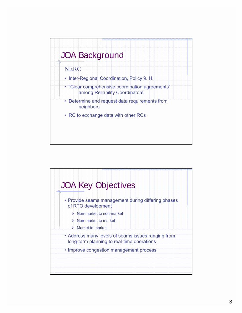
JOA BackgroundFERC• Order 2000, RTO Must Ensure Integration of:
� Reliability practices within an interconnection
� Market practices among regions
• RTO Must Develop Plan to Deal with Loop Flow
• MISO – PJM to address Alliance Companies’ “Seams”
• Condition included in SPP RTO Approval Order
3
JOA BackgroundNERC• Inter-Regional Coordination, Policy 9. H.
• “Clear comprehensive coordination agreements”among Reliability Coordinators
• Determine and request data requirements from neighbors
• RC to exchange data with other RCs
JOA Key Objectives
• Provide seams management during differing phases of RTO development� Non-market to non-market
� Non-market to market
� Market to market
• Address many levels of seams issues ranging from long-term planning to real-time operations
• Improve congestion management process

4
JOA Development Inputs
• MISO-PJM JOA� Filed at FERC
• MISO-PJM CMP� Reviewed and approved by NERC
• Previous data exchange and ATC coordination principles developed by MISO, SPP, and Alliance RTO participants
• August 14 blackout joint task force report
JOA Key Elements• Phased coordination elements and triggers, Article III
• Data exchange, Article IV� Includes exchange of real-time data, operations planning
data,and models
• ATC coordination, Article V� Prescribes ATC data to be shared, common approach to ATC
calculations, and honoring of third-party limits
• Reciprocal coordination of flowgates, Article VI
• Maintenance outage coordination, Article VII

5
JOA Key Elements• Coordinated emergency procedures, Article VIII
• Coordinated transmission planning, Article IX� Covers expansion planning, interconnection analysis, and
System Impact Studies
• Coordinated scheduling and checkouts, Article X
• Reactive power coordination, Article XI
• Other market-to-market items to be explored, Article XII
JOA Next Steps• Continue review with stakeholders – thru August
13, 2004
• Collect and post comments – thru August 13, 2004
• Issue revised JOA – August 16, 2004
• File at FERC – August 20, 2004

6
Coordination Phases, Article III• Phase 1 – Non-market to Non-market
� Data exchange
� ATC calculation/coordination
� Outage coordination
� Emergency procedure coordination
� Transmission planning coordination
� Scheduling/checkout coordination
Coordination Phases, Article III• Phase 2 – Non-market to Market
� Phase 1 items
� Reciprocal flowgate coordination
� Congestion management process
• Phase 3 – Market to Market� Phase 1 and 2 items
� Consistent energy prices at borders
� Coordinated emergency generation redispatch

7
Data Exchange, Article IV• Real-time operating data
• Projected operating data
• SCADA data
• EMS Models
• Operations planning data
ATC Coordination, Article V• Require types and periodicity of data to be shared
� Outage schedules for next 12 months updated at least daily
� Dispatch order/unit commitment updated as required
� Reservations posted daily with new requests and status changes updated hourly
� Reservations to be excluded from ATC calculations
� Load forecasts posted daily for each AFC period
� Firm and non-firm AFCs
� Flowgates, ratings and response factor cutoffs to be considered
� Network model updates at least prior to peak load season
� Dynamic schedule flows

8
ATC Coordination, Article V• Parties will respect each other’s flowgate limitations
• Parties will use the response factor cutoff that the owning party uses on the foreign flowgate in AFC determinations
Reciprocal Flowgate Coord., Article VI• Allocates AFC, based on historical usage, for use in
market dispatch and provision of transmission service
• Real-time actions governed by Congestion Management Process� Based on MISO-PJM white paper approved by NERC
� Allows TLR process to properly recognize impacts of market operations
• To be discussed in more detail later
9
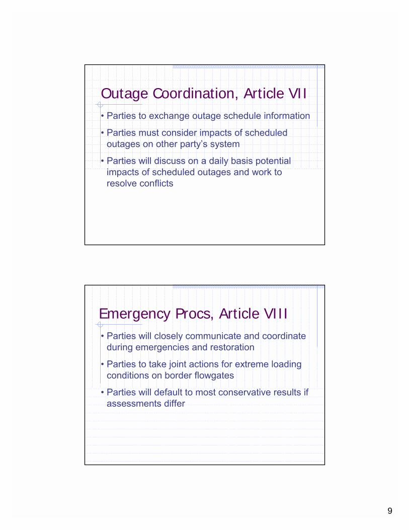
Outage Coordination, Article VII• Parties to exchange outage schedule information
• Parties must consider impacts of scheduled outages on other party’s system
• Parties will discuss on a daily basis potential impacts of scheduled outages and work to resolve conflicts
Emergency Procs, Article VIII• Parties will closely communicate and coordinate
during emergencies and restoration
• Parties to take joint actions for extreme loading conditions on border flowgates
• Parties will default to most conservative results if assessments differ

10
Coordinated Planning, Article IX• Establishes Joint Planning Committee
� Consists of planning staffs of parties
� Prepares procedures for model development
� Prepares the Coordinated Plan
� Coordinates all planning activities
� Support review of coordinated plans by Federal and State entities
• Establishes Inter-regional Planning Stakeholder Advisory Committee� Drawn from stakeholder planning committees of Parties
� Facilitates stakeholder review and input into Coordinated Plan
Coordinated Planning, Article IX• Data exchanged at least annually to support
coordinated planning� Data needed for load flow, short-circuit, stability cases
� Full detail planning models
� Planning and reliability assessment documents
� Status and timing of system upgrades
� Transmission system maps
� Contingency list and breaker diagrams
� Status of interconnection and long-term service requests

11
Coordinated Planning, Article IX• Parties to perform single system planning and
share results
• Parties to develop Coordinated System Plan� incorporates each party’s annual planning reports
� includes comprehensive, coordinated regional expansion study performed at least every 3 yrs
• Coordinate analysis of interconnection requests
• Coordinate analysis of long-term firm service requests
Coordinated Planning, Article IX• Costs for upgrades associated with
interconnections and transmission service are recovered under terms of applicable tariff
• Costs for upgrades identified in Coordinated System Plan assigned to Parties� JPC to develop procedures for evaluating party’s
contribution to constraint and benefit received from upgrade
� JPC to propose allocation of costs
12
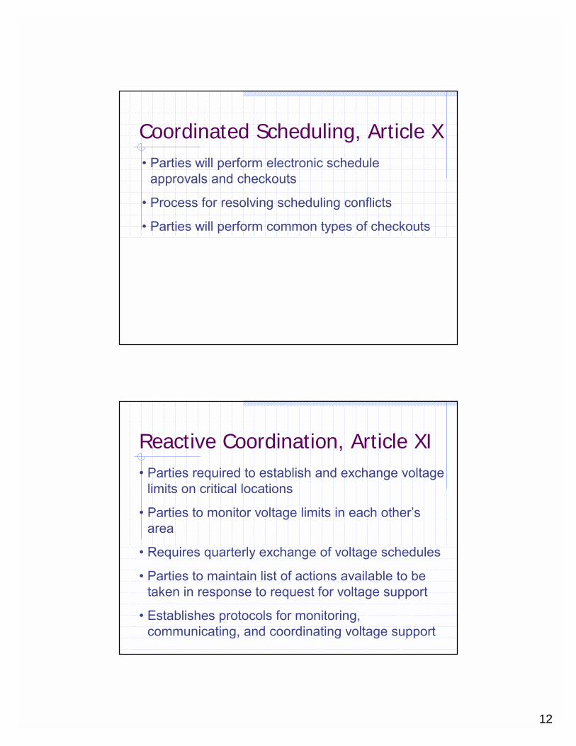
Coordinated Scheduling, Article X• Parties will perform electronic schedule
approvals and checkouts
• Process for resolving scheduling conflicts
• Parties will perform common types of checkouts
Reactive Coordination, Article XI• Parties required to establish and exchange voltage
limits on critical locations
• Parties to monitor voltage limits in each other’s area
• Requires quarterly exchange of voltage schedules
• Parties to maintain list of actions available to be taken in response to request for voltage support
• Establishes protocols for monitoring, communicating, and coordinating voltage support

13
Additional Provisions, Article XII• Parties will work to develop consistency of energy
prices at the border
• Parties will explore market methods for relieving each other’s binding constraints in real-time
• Should develop consistent proxy bus modeling approaches at borders
• Coordinated emergency redispatch
• Equitable compensation for generation redispatch
JOA Overview
Questions?

14
Congestion Management Process
Topics
Definitions� Flowgates� ATC/AFCFlowgate Coordination� Allocate� Adhere� Act

15
Flowgate DefinitionConsists of a group of transmission elements that have been defined as a potential for congestion due to Thermal, Reliability and/or Stability concerns.Can Be Created Using Two Methods:� PTDF: Flowgate exists due to a pre-
contingent scenario and looks for relief on the monitored elements prior to a planned outage event
� OTDF: Flowgate exists due to a post-contingent scenario and looks for relief on the monitored element while simulating the contingency
Flowgate Definition
Elements of a Flowgate:- Monitored Element(s) : Power System
Element(s) that requires MW relief- Contingent Element(s) : Power System
Element that will have an action that causes the monitored element to become congested and/or unreliable (i.e. taking an element out of service) (OTDF Only)

16
Flowgate Definition
- Total Transfer Capability (TTC)- The amount of MW flow that can occur on the
flowgate due to the limitation it defines.- Transfer Reliability Margin (TRM)
- The amount of MWs that must be reserved on the flowgate to protect against the next contingency, reserve sharing agreements, and uncertainties (load forecast etc.)
- Capacity Benefit Margin (CBM)- The amount of MW capability that is reserved by
the transmission provider for load-serving entities, whose loads are located on the transmission provider’s system
Flowgate Example
NPPD (B)
WAPA (A) MISO (C)
SWPP (D)
1
2
34
Flowgate: West East 1Monitored: Element 3 and 4Contingent: None
Flowgate West Voltage 1Monitored: Element 1Contingent: Element 2
17
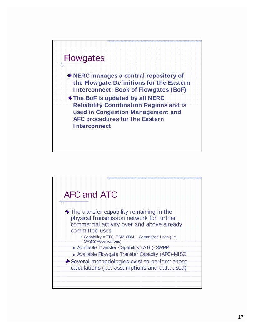
Flowgates
NERC manages a central repository of the Flowgate Definitions for the Eastern Interconnect: Book of Flowgates (BoF)The BoF is updated by all NERC Reliability Coordination Regions and is used in Congestion Management and AFC procedures for the Eastern Interconnect.
AFC and ATC
The transfer capability remaining in the physical transmission network for further commercial activity over and above already committed uses.
� Capability =TTC- TRM-CBM – Committed Uses (i.e. OASIS Reservations)
� Available Transfer Capability (ATC)-SWPP� Available Flowgate Transfer Capacity (AFC)-MISO
Several methodologies exist to perform these calculations (i.e. assumptions and data used)

18
JOA Flowgate Coordination
Problem: Flowgates are in TLR Solution: Mitigate overselling of Flowgates in the AFC/ATC realm. Increase accuracy of Congestion Management to create more efficient relief.
JOA Flowgate Coordination
Main Steps:� Allocate capacity of the defined Flowgates
between JOA parties for coordination� Adhere to this allocation of capacity when selling
transmission service. Don’t oversell your portion of the flowgate
� Act to remove excess MW flow on Flowgates in real time by re-dispatching back to agreed to base usage based on Market Rules and NERC Transmission Loading Relief Procedure
19
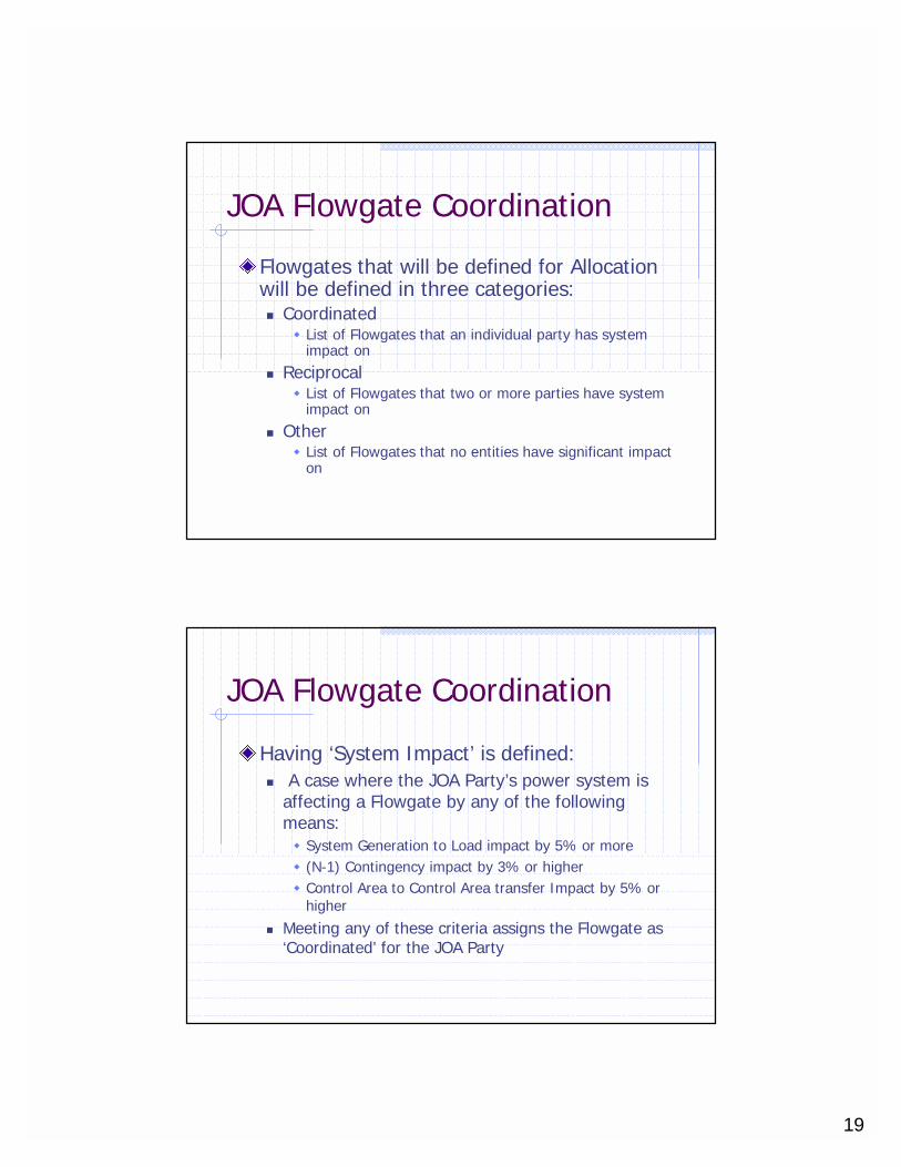
JOA Flowgate Coordination
Flowgates that will be defined for Allocation will be defined in three categories:� Coordinated
� List of Flowgates that an individual party has system impact on
� Reciprocal� List of Flowgates that two or more parties have system
impact on
� Other� List of Flowgates that no entities have significant impact
on
JOA Flowgate Coordination
Having ‘System Impact’ is defined:� A case where the JOA Party’s power system is
affecting a Flowgate by any of the following means:� System Generation to Load impact by 5% or more� (N-1) Contingency impact by 3% or higher� Control Area to Control Area transfer Impact by 5% or
higher
� Meeting any of these criteria assigns the Flowgate as ‘Coordinated’ for the JOA Party

20
JOA Flowgate Coordination
Each Party’s Coordinated Flowgates are compared with the other JOA participant lists, if a Flowgate exists on one or more lists the Flowgate becomes ‘Reciprocal’ for the entities.
Reciprocal Flowgates will always participate in AFC/ATC and congestion management coordination between the JOA parties
MISO Coordinated Flowgates (By NERC Region, Includes MISO Internal Facilities)
SPP- 43
ECAR- 182
MAIN- 276
MAPP- 110
SERC- 98NPCC- 13
MAAC- 54
43182
276
110
98
13
54
MISO Total - 776
21
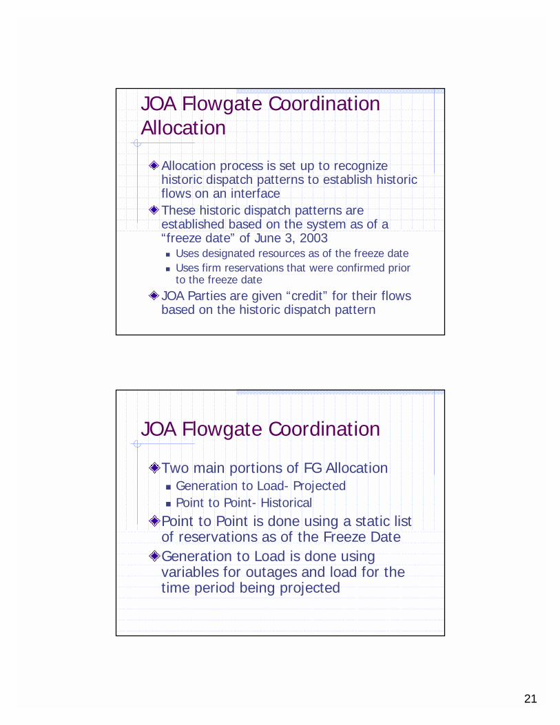
JOA Flowgate CoordinationAllocation
Allocation process is set up to recognize historic dispatch patterns to establish historic flows on an interfaceThese historic dispatch patterns are established based on the system as of a “freeze date” of June 3, 2003� Uses designated resources as of the freeze date� Uses firm reservations that were confirmed prior
to the freeze dateJOA Parties are given “credit” for their flows based on the historic dispatch pattern
JOA Flowgate Coordination
Two main portions of FG Allocation� Generation to Load- Projected� Point to Point- HistoricalPoint to Point is done using a static list of reservations as of the Freeze DateGeneration to Load is done using variables for outages and load for the time period being projected
22
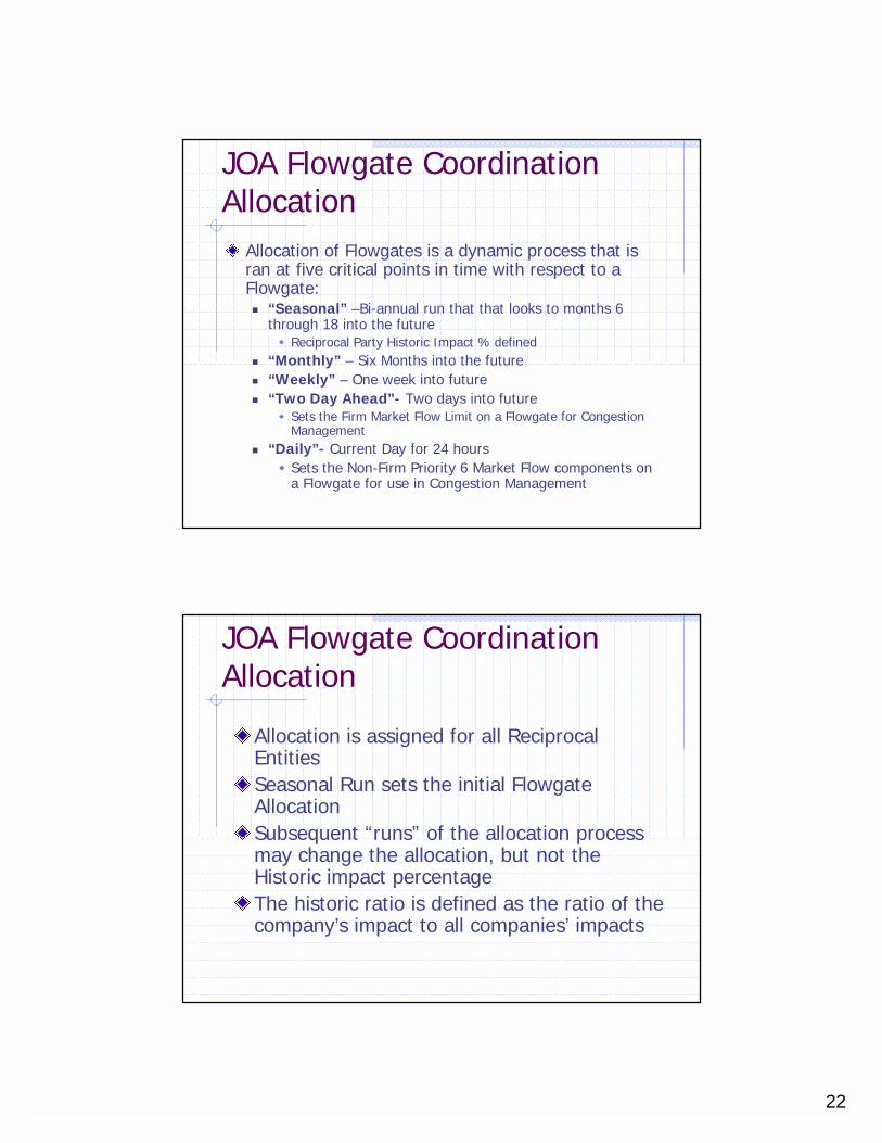
JOA Flowgate CoordinationAllocation
Allocation of Flowgates is a dynamic process that is ran at five critical points in time with respect to a Flowgate:� “Seasonal” –Bi-annual run that that looks to months 6
through 18 into the future� Reciprocal Party Historic Impact % defined
� “Monthly” – Six Months into the future � “Weekly” – One week into future� “Two Day Ahead”- Two days into future
� Sets the Firm Market Flow Limit on a Flowgate for Congestion Management
� “Daily”- Current Day for 24 hours� Sets the Non-Firm Priority 6 Market Flow components on
a Flowgate for use in Congestion Management
JOA Flowgate CoordinationAllocation
Allocation is assigned for all Reciprocal EntitiesSeasonal Run sets the initial Flowgate AllocationSubsequent “runs” of the allocation process may change the allocation, but not the Historic impact percentageThe historic ratio is defined as the ratio of the company’s impact to all companies’ impacts

23
JOA Flowgate CoordinationAllocation
Allocation for an JOA Reciprocal Entity will not be decreased in value for any given RunA portion of the Flowgate Capacity is reserved for potential additional Reciprocal Entities. � This is defined as an ‘Expansion Margin’ for the Flowgate� The ‘Expansion Margin’ is released for a Flowgate 6 months
prior to the current day if additional entities have not indicated they will be pursuing a Reciprocal relationship with the JOA entity
JOA Flowgate CoordinationAllocation
Historical Flows are Identified and Allocated with two components:� Generation to Load (GLD)
� Based on Historic Designated Resource Generator Set� Combined with necessary data: PSSE Model (GLD
Factors), Outages, Generation Merit Order, and Load Forecast
� Historical Point to Point� Based on Historic Reservation Set- from Freeze Date
� Combined with necessary data: PSSE Model (point-to-point impacts), Outages
� Credit assigned based on detailed rules� Imports, Export, and Wheels treated differently� “Owner” of Flowgate accounted for

24
NERC OC FEB ‘03
Calculating the Generation to Load Flow
Therefore …
Market Flow across Flowgate “A”: (20) + (7.5)+ (-6)
= 21.5 MWTherefore …
Generation to Load forFlowgate “A”:
(20) + (7.5)(-6)
= 27.5 MW Forward
Swing Bus
Load Busses
Generation Bus #1
GSF1 = .50 GSF3 = -.10
LSF = .10
Generation Bus #3
GSF = Generation Shift FactorImpact on Flowgate “A” from Individual Generator to Swing Bus
LSF = Load Shift Factor Impact on Flowgate “A” from Swing Bus to All Load
Flowgate“A”
MISO
SPP
MAPP
50 MW50
MW50
MW50
MW30
MW30
MW
10 MW10
MW50
MW50
MW70
MW70
MW
GLDF = Algebraic Sum of GSF – LSF
Therefore …
GSF1 – LSF = .5 - .1 = .4
GSF2 – LSF = .25 - .1 = .15
GSF3 – LSF = ( -.1) - .1 = (-.2)
Therefore …GLDF1 = .4 x 50MW = 20 MW Impact
GLDF2 = .15 x 50MW = 7.5 MW Impact
GLDF3 = (-.2) x 30MW = -6 MW Impact
= -6 MW Reverse(27.5) 21.5 MW Net+ (-6) =
GSF2 = .25
Generation Bus #2
Point to Point Impacts
Based on� Firm Reservations Confirmed (filtered and credited
using special methodology) as of June 3rd, 2003 Freeze Date� Filtering eliminates duplicate legs� Crediting assigns impacts based on source, sink, and
provider
� Impacts for the Point to Point Reservations are calculated for the time period of the allocation� Uses current IDC model� Uses current outages

25
Point to Point Impacts
Customized List for each TP� Begin with all reservations on that TP’s node (the
primary provider’s node)� Add reservations from 1st Tier TPs that are NOT
“wheel throughs” and do NOT Source or Sink in the primary provider’s service territory
� Continue to 2nd tier, excluding “wheel throughs” and reservations that sink in the primary provider’s or the 1st Tier TPs’ service territories
� Continue until all appropriate TPs have been considered
Point to Point Impacts
For each flowgate, determine the “owner” and use their filtered reservation list For each reservation in the list� If it is a Import or Export, split the impacts
50/50 between the Source and Sink TPs� If it is a “wheel through,” split the impacts
25/50/25 between the Source, Wheeling, and Sink TPs

26
JOA Flowgate CoordinationAllocation
Point-to-Point and Generation to Load sorted into two categories for the forward and reverse direction of the Flowgate:� A. Impacts Greater Than/Equal To 5%
� (GLD + Pt-to-Pt)� B. Impacts Less Than 5%
� (GLD + Pt-to-Pt)
Flowgate Limit Definition is Determined� Limit = TTC-CBM-TRM
Allocation steps are taken to assign Flowgate Capacity to each JOA entity for all Reciprocal Flowgates in both the Forward and Reverse direction
JOA Flowgate CoordinationAllocation
Three Main Allocation Steps� A. Impacts Greater Than/Equal To 5%
� All entities are granted a share of the flowgate equivalent to their flows based on impacts of 5% or greater
� B. Impacts Less Than 5%� If, after step A, there is still unclaimed flowgate capability,
Reciprocal entities are granted a pro rata share (based on their<5% impacts) of that capability up to the sum of their <5% impacts
� C. Additional Flowgate Capability� If, after step B, there is still unclaimed flowgate capability,
Reciprocal Entities are granted a pro rata share (based on theirhistoric impact percentage) of that capability.
27
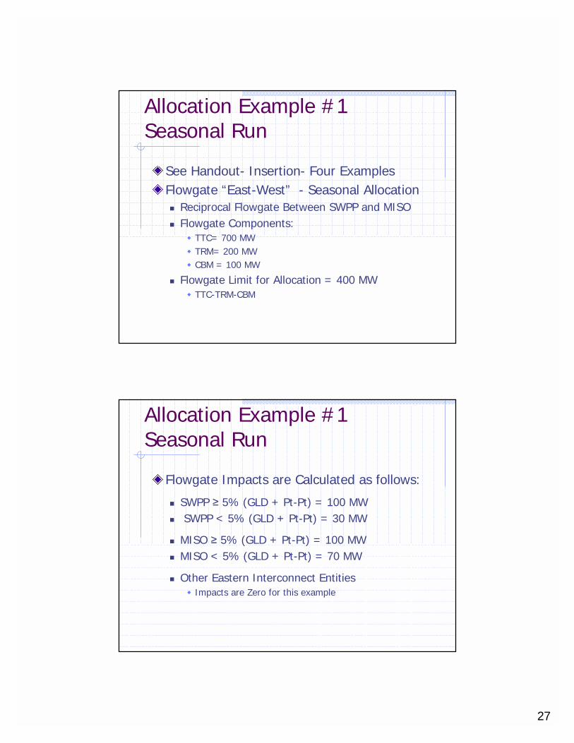
Allocation Example #1Seasonal Run
See Handout- Insertion- Four ExamplesFlowgate “East-West” - Seasonal Allocation� Reciprocal Flowgate Between SWPP and MISO� Flowgate Components:
� TTC= 700 MW� TRM= 200 MW� CBM = 100 MW
� Flowgate Limit for Allocation = 400 MW� TTC-TRM-CBM
Allocation Example #1Seasonal Run
Flowgate Impacts are Calculated as follows:
� SWPP ≥ 5% (GLD + Pt-Pt) = 100 MW� SWPP < 5% (GLD + Pt-Pt) = 30 MW
� MISO ≥ 5% (GLD + Pt-Pt) = 100 MW� MISO < 5% (GLD + Pt-Pt) = 70 MW
� Other Eastern Interconnect Entities� Impacts are Zero for this example

28
Allocation Example #1Seasonal Run
A. First use the ≥ 5% impacts from both Parties
[Limit - ≥ 5% Impacts = Remaining Room]400MW – (100MW + 100MW) = 200MW
B. Next use the <5% impacts
[Remaining Room - <5% Impacts]200MW – (30MW + 70MW) = 100MW
C. Finally, share the remaining MW based on the Historic Ratio[Remaining Room *Historical %]SWPP= 100MW X (130MW/300MW) = 43MWMISO = 100MW X (170MW/300MW) = 57MW
Allocation Example #1Seasonal Run
TOTAL ALLOCATIONS :Seasonal Run for Flowgate “East-West”:
SWPP = 100MW + 30MW + 43MW = 173MW
MISO = 100MW + 70MW + 57MW = 227MWOther = 0 MW
173MW + 227MW +0MW = 400MW (FG Limit)Expansion Margin = 0 (<5% + Extra MW Added for Other)
*Due to Other Entities having Zero Impact on FG
29
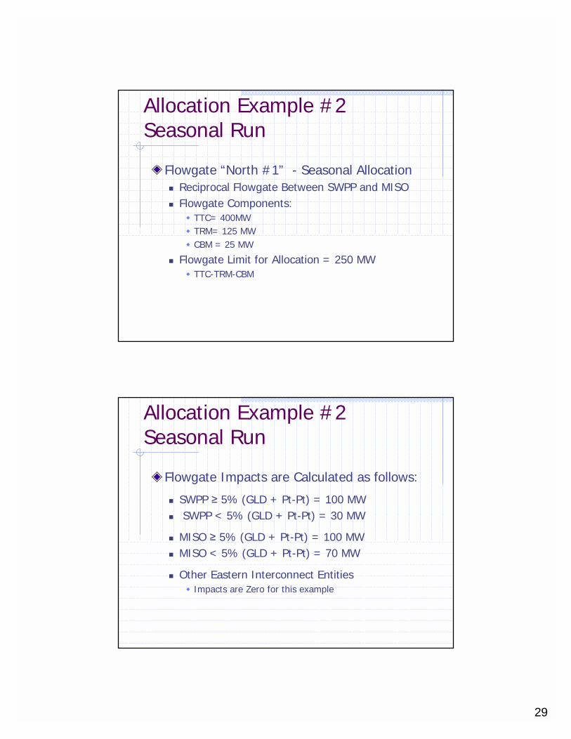
Allocation Example #2Seasonal Run
Flowgate “North #1” - Seasonal Allocation� Reciprocal Flowgate Between SWPP and MISO� Flowgate Components:
� TTC= 400MW� TRM= 125 MW� CBM = 25 MW
� Flowgate Limit for Allocation = 250 MW� TTC-TRM-CBM
Allocation Example #2Seasonal Run
Flowgate Impacts are Calculated as follows:
� SWPP ≥ 5% (GLD + Pt-Pt) = 100 MW� SWPP < 5% (GLD + Pt-Pt) = 30 MW
� MISO ≥ 5% (GLD + Pt-Pt) = 100 MW� MISO < 5% (GLD + Pt-Pt) = 70 MW
� Other Eastern Interconnect Entities� Impacts are Zero for this example

30
Allocation Example #2Seasonal Run
A. First use the ≥ 5% impacts from All Parties
[Limit - ≥ 5% Impacts = Remaining Room]
250MW – (100MW + 100MW+0MW) = 50MW
B. Next use the <5% impacts(Since there is not room on the FG for all <5% so a pro rata share of the <5% impacts will be used
[Remaining Room - <5% Impacts]SWPP = 50MW X (30MW/100MW) = 15MWMISO = 50MW X (70MW/100MW) = 35MW
Allocation Example #2Seasonal Run
TOTAL ALLOCATIONS Seasonal Run for Flowgate “North 1”:
SWPP = 100MW + 15= 115MW
MISO = 100MW + 35MW = 135MW
Other = 0MW
115MW + 135MW +0MW = 250MW (FG Limit)Expansion Margin = 0 MW*(<5% + Extra MW Added for Other)
*Due to Other Entities having Zero Impact on FG
31
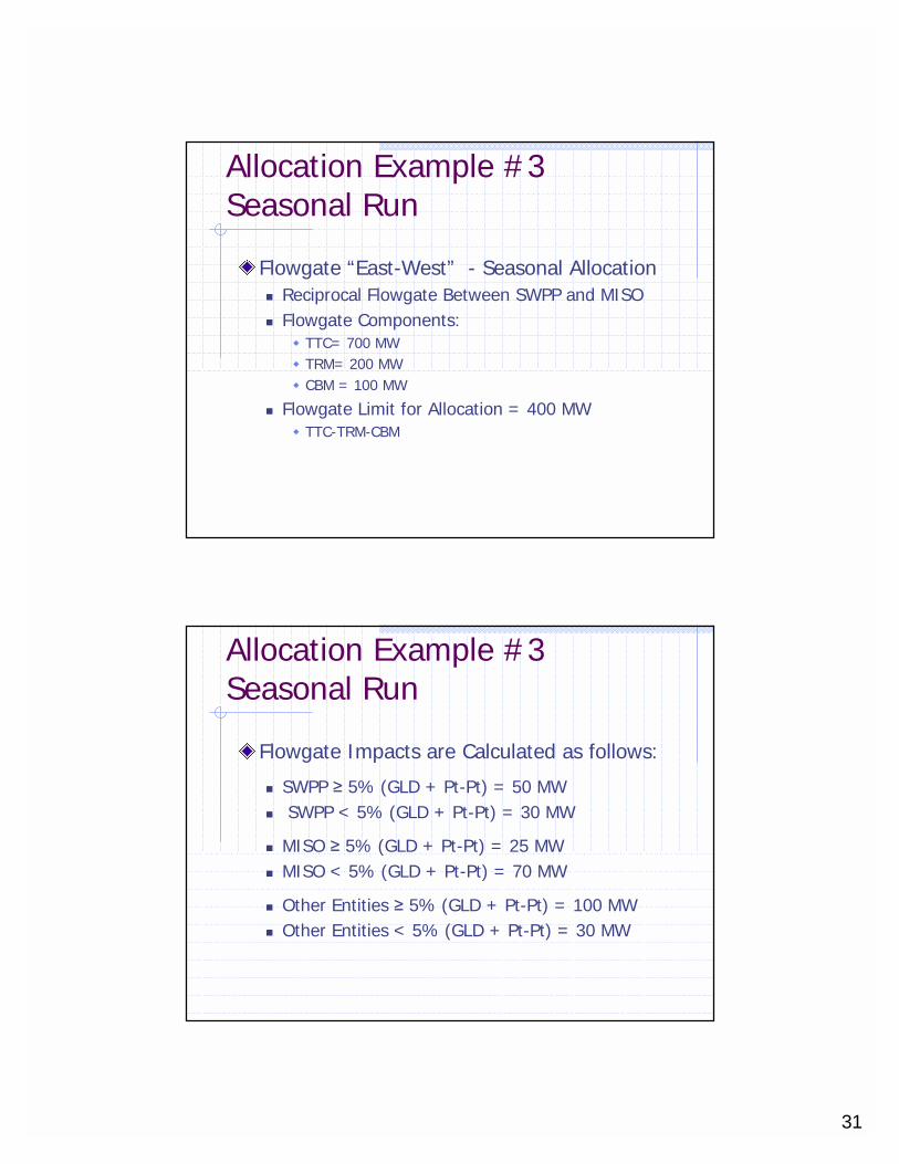
Allocation Example #3Seasonal Run
Flowgate “East-West” - Seasonal Allocation� Reciprocal Flowgate Between SWPP and MISO� Flowgate Components:
� TTC= 700 MW� TRM= 200 MW� CBM = 100 MW
� Flowgate Limit for Allocation = 400 MW� TTC-TRM-CBM
Allocation Example #3Seasonal Run
Flowgate Impacts are Calculated as follows:
� SWPP ≥ 5% (GLD + Pt-Pt) = 50 MW� SWPP < 5% (GLD + Pt-Pt) = 30 MW
� MISO ≥ 5% (GLD + Pt-Pt) = 25 MW� MISO < 5% (GLD + Pt-Pt) = 70 MW
� Other Entities ≥ 5% (GLD + Pt-Pt) = 100 MW� Other Entities < 5% (GLD + Pt-Pt) = 30 MW

32
Allocation Example #3Seasonal Run
A. First use the ≥ 5% impacts from All Parties
[Limit - ≥ 5% Impacts = Remaining Room]400MW – (50MW + 25MW+100MW) = 225MW
B. Next use the <5% impacts
[Remaining Room - <5% Impacts]225MW – (30MW + 70MW+30MW) = 95MW
C. Finally, share the remaining MW based on the Historic Ratio[Remaining Room *Historical %]
SWPP= 95MW X (80MW/305MW) = 25MWMISO = 95MW X (95MW/305MW) = 29MWOther = 95MW X (130MW/305MW)=40 MW
Allocation Example #3Seasonal Run
TOTAL ALLOCATIONS :Seasonal Run for Flowgate “East-West”
SWPP = 50MW + 30MW + 25MW = 105MW
MISO = 25MW + 70MW + 29MW = 124MW
Other = 100 MW + 30MW + 40MW =171MW
105MW + 124MW +171MW = 400MW (FG Limit)
Expansion Margin = (<5% + Extra MW Added for Other) = 70 MW*
*Will be released for Allocation Between SWPP and MISO in Next Allocation (Monthly Run) if no entity indicates they want to become a Reciprocal Entity
33
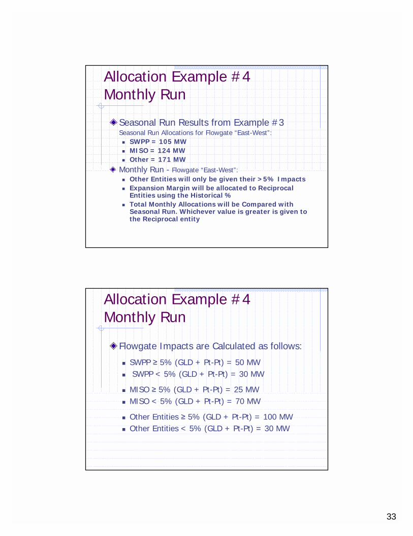
Allocation Example #4Monthly Run
Seasonal Run Results from Example #3Seasonal Run Allocations for Flowgate “East-West”:� SWPP = 105 MW� MISO = 124 MW� Other = 171 MW
Monthly Run - Flowgate “East-West”:� Other Entities will only be given their >5% Impacts� Expansion Margin will be allocated to Reciprocal
Entities using the Historical %� Total Monthly Allocations will be Compared with
Seasonal Run. Whichever value is greater is given to the Reciprocal entity
Allocation Example #4Monthly Run
Flowgate Impacts are Calculated as follows:
� SWPP ≥ 5% (GLD + Pt-Pt) = 50 MW� SWPP < 5% (GLD + Pt-Pt) = 30 MW
� MISO ≥ 5% (GLD + Pt-Pt) = 25 MW� MISO < 5% (GLD + Pt-Pt) = 70 MW
� Other Entities ≥ 5% (GLD + Pt-Pt) = 100 MW� Other Entities < 5% (GLD + Pt-Pt) = 30 MW

34
Allocation Example #4Monthly Run
A. First use the ≥ 5% impacts from All Parties
[Limit - ≥ 5% Impacts = Remaining Room]400MW – (50MW + 25MW+100MW) = 225MW
B. Next use the <5% impacts from the Reciprocal Parties
[Remaining Room - <5% Impacts]225MW – (30MW + 70MW) = 125MW
C. Finally, share the remaining MW based on the Historic Ratio[Remaining Room *Historical % of Reciprocal Entities]
SWPP= 125MW X (80MW/175MW) = 57MWMISO = 125MW X (95MW/175MW) = 68MW
*Expansion Margin is now Zero
Allocation Example #4Monthly Run
TOTAL ALLOCATIONS For Monthly Run:[>5% Impacts + <5% Impacts +Extra Room]
SWPP = 50MW + 30MW + 57MW = 137MW
MISO = 25MW + 70MW + 68MW = 163MW
Other = 100 MW + 0MW + 0MW =100 MW
137MW + 163MW +100MW = 400MW (FG Limit)Expansion Margin = 0 MW*(<5% + Extra MW Added for Other)

35
Allocation Example #4
Compare Allocations to Seasonal Run to ensure no Allocations are reduced for the Reciprocal EntitiesSWPP� Seasonal = 105 MW� Monthly = 137 MW
MISO� Seasonal = 124 MW� Monthly = 163 MW
JOA Flowgate CoordinationAdhere
Once the Flowgate Allocation is determined for a time period. The Reciprocal entity will use this value to determine if they can utilize more of the Flowgate Capacity while operating the power system for that time period

36
JOA Flowgate CoordinationAdhere
AFC/ATC process will have two components• Reciprocal Allocation Check – verifies entities are
staying within their allocation limits• Reliability Check – verifies system is not being oversold
The AFC/ATC process will use the lowest of these two numbers when deciding to grant transmission serviceIf Reciprocal Allocation Check is lower, then entity will be bound to their shareIf Reliability Check is lower, entity will be bound to reliability limitsThe Reliability Check utilizes the existing AFC/ATC processes
Reciprocal Allocation CheckBegin with the AllocationSubtract net estimate of forecast Gen to Load impacts (down to 0%)Subtract impacts of sold PTP reservations in the forward direction (down to 0%)Add 15% of the impacts of counter flowing PTP reservationsRemainder is Available Share of Total Flowgate Capability
abilityTotalFGCapAvailShare
Pt-to-PtCounter flowFWDSoldPt-to-Pt
GentoLoadNetEstimateAllocation
)%(15
)(
+−−

37
Reciprocal Allocation CheckExampleAllocation = 100MWGen to Load Positive Impacts = 42MW
Gen to Load Counterflow Effect = 20MW
100MW – (42MW – 20MW) = 78MW
Point to Point Positive Impacts = 58MW
Point to Point Counterflow Impacts 45MW
78MW – (58MW – (.15 X 45MW) = 27MW
*Reciprocal Entity Not Utilizing more than the assigned allocation- continue
lli
MW
MWMW
MWMWMW
27
)45%(1558
2042100
+−
−−
JOA Flowgate CoordinationMarket Flow
When approaching near real time Market Entities that are Reciprocal Parties will be required to submit real time Market Flow information for Regional Congestion Management– Current/Next HourMarket Flow is the summation of the impact of the market generation (at current output) on a Flowgate for a given time period� MF = Current Gen MW* GLD Factor – (Pt-Pt Transactions)� Summed for all generation in the market footprint
38
JOA Flowgate CoordinationMarket Flow
Market Flow is communicated as three components:� Firm Network = Historic NNL � Non-Firm Priority 6- (ED-6)� Non-Firm Priority 2- (ED-2)
This priority is used during Regional Congestion Management procedures (NERC TLR)
JOA Flowgate CoordinationMarket Flow
Determination of the Market Flow components:� Firm Network= Historic NNL
� Two Day Ahead NNL sets the Firm Market Flow Limit� If real time Market Generation impact on the Flowgate is less
than than this limit all Market Flow is considered Firm Network� ED-6
� Initial ED-6 limit is set during the Daily Run by comparing the estimated Daily allocation with the Two Day Ahead NNL.
� Any excess allocation will be put into the ED-6 bucket and sets the ED-6 limit for the FG
� ED-2� Any real-time calculated Market Flow Above the ED-6 value on
a Flowgate will be put into the Priority 2 category
39
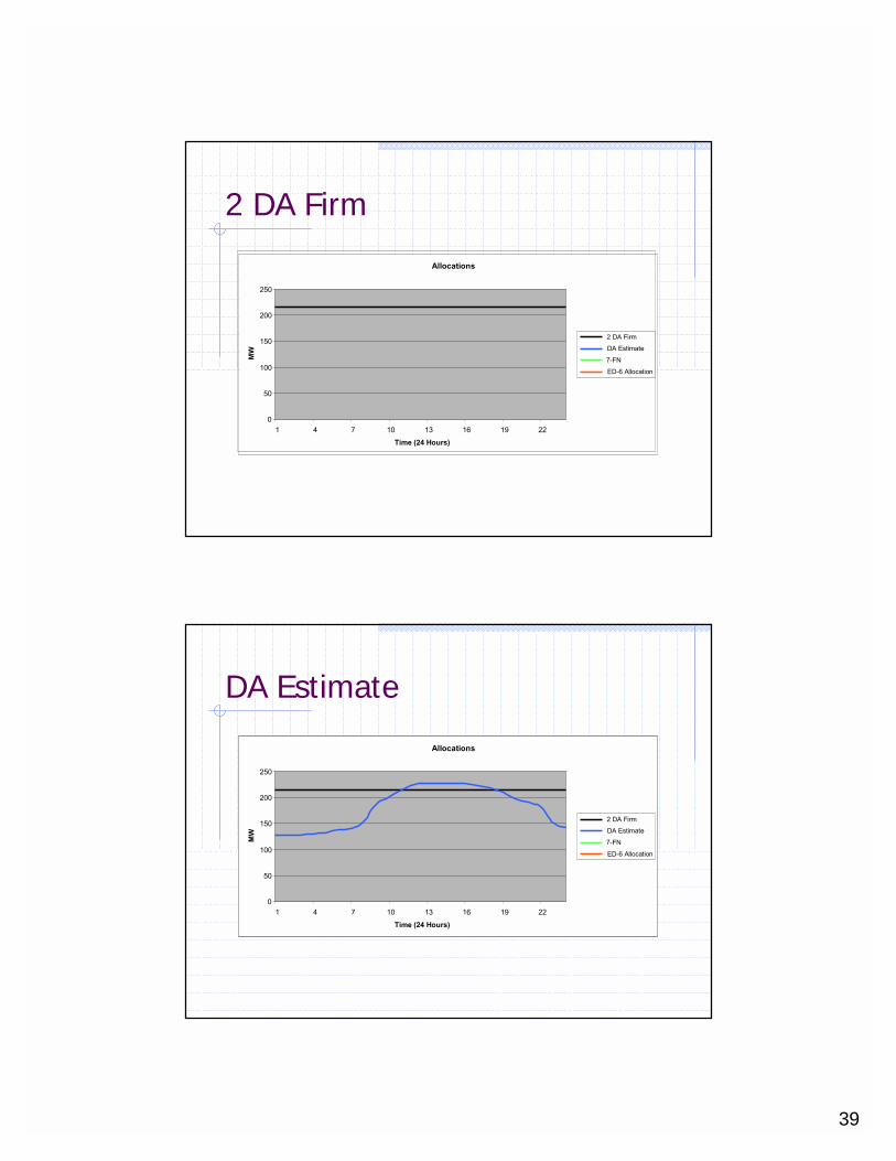
2 DA Firm
Allocations
0
50
100
150
200
250
1 4 7 10 13 16 19 22
Time (24 Hours)
MW
2 DA Firm
DA Estimate
7-FN
ED-6 Allocation
DA Estimate
Allocations
0
50
100
150
200
250
1 4 7 10 13 16 19 22
Time (24 Hours)
MW
2 DA Firm
DA Estimate
7-FN
ED-6 Allocation

40
Firm Limit
Allocations
0
50
100
150
200
250
1 4 7 10 13 16 19 22
Time (24 Hours)
MW
2 DA Firm
DA Estimate
7-FN
ED-6 Allocation
ED-6 Limit
Allocations
0
50
100
150
200
250
1 4 7 10 13 16 19 22
Time (24 Hours)
MW
2 DA Firm
DA Estimate
7-FN
ED-6 Allocation
Anything above the combined 7-FN and ED-6
is treated as ED-2

41
JOA Flowgate CoordinationMarket Flow
Flowgate A: Limit =300 MW
Example 1: UnconstrainedHR XX:00:Market Flow = 150 MW(Market Generation – Pt-Pt Tags)
Components: FIRM =75ED-6 =75ED-2 =0
Firm
ED-6
ED-2
75 MW FIRM Limit
225 MW ED-6 Limit
Example 2: ConstrainedHR XX:00 +1Market Flow = 600(Market Generation – Pt-Pt Tags)
Components: FIRM =75ED-6 =150ED-2 =375
Historic NNL
TLR- The Future
Market Entities Plan to use TLR in conjunction with Market Re-Dispatch(LMP) relieve constraints in the regionMore Real-Time Data in TLR Process� Market Flow� Marginal Units
Market Flow will be curtailed along side of Non-Firm and Firm Point to Point Transactions

42
Summary
Flowgate Coordination Involves� AFC/ATC � Congestion Management
JOA Reciprocal Parties Should � Allocate Flowgates� Adhere to the Allocations� Act on Congestion
Questions?

43
Enhancements Under Consideration
TRM and CBM MarginsSystem Expansion50% Point to Point Impacts on ASTFC3rd Party AllocationsTreatment of Unused Allocation
Allocation Special Topics

44
TRM and CBM Margins
Currently, deduct TRM and CBM from the total flowgate rating prior to determining the allocationPropose to remove the CBM component from allocation calculationTP can use whatever CBM they feel appropriate for their share of allocation
System ExpansionCMP has a specific freeze date on transactions and generationUse same freeze date for network topology changesBenefits of transmission enhancements accrue to the TP responsible for the enhancementTransmission enhancements made after the freeze date excluded from allocation process

45
Implement 50% Point to Point Impacts
When request involves another TP to complete the party, allocation required for only 50% impacts
Third Party Participationin AllocationCurrently hold an expansion margin for third parties beyond 6 monthsDoes this provide proper incentive to participate?Currently include third party flowgates in allocationDoes this provide proper incentive to participate?

46
Treatment of Unused Allocation Between MISO and SPP
Unused allocation issue is where either MISO or SPP are restricted due to lack of an allocation while other party still has an unused allocationMISO and SPP will address two situations where this occursFirst: To avoid building new facilities for long term firm requests because one party does not have an allocationSecond: To not have unused allocations in real-time by one party while other party is restricted
Sharing of Unused Allocation During First 14 Days
Goal is to not have one party have unused allocation in real-time while other party restrictedThere would be no change in the allocation. Would recognize that one party was not going to fully utilize their allocation and it is available to other partyBoth parties would have to get back to their original allocation if congestion occurredSince the allocations have not changed, the sharing of unused allocation would be uncompensated - Use It or Lose It

47
Three Situations When This Can Occur
Both parties are on the path, one with an allocation and the other with no allocation. In order to accommodate the transaction, the party with the allocation must agree to decrement for the other party’s 50% impact. If congestion occurs, the party with the allocation is responsible for 100% impacts. Must also have AFCs before approve.
Three Situations When This Can OccurThe party with no allocation is on the path, but not the other party. The party with no allocation reduces its allocation by the impact and then adds its negative allocation to the positive allocation of the other party. If net number is positive and have AFCs, can approve.

48
Three Situations When This Can Occur
On a day-ahead basis, MISO and SPP will pool their unused allocations to operate a market. If MISO allocation is not fully utilized, it becomes available to SPP market. If SPP allocation is not fully utilized, it becomes available to MISO market. No AFC analysis associated with market flows.
Acquiring an Unused Allocation During Months 1 Through 18
Goal is to not have one party build new facilities in response to a long-term request because they do not have an allocationThere would be a exchange of allocation provided there are no other allocation commitments and have AFCsCredits will be given for use of allocation that can be applied to other flowgates in the same time periodLong-term firm request must be confirmed for the allocation exchange to occur. Rolled-over service based on this process will continue to create credits
49
Use of Credits in Exchangefor Allocation
Only long-term firm requests can initiate an allocation exchange. This may result in creation of creditsCredits can be applied to unused allocations of the deficient entity during the same time periodA party with credits can apply these either to long-term firm requests or to obtain unused allocations even when no long-term firm request existsTo the extent credits have not been used before the time period ends, the credits expire
Example
Consider a flowgate XXYY. Its TFC is 400, its AFC is 200. MISO has an allocation of 100 and has used 90. SPP has an allocation of 300 and has used 200.
MISO gets a request on that flowgate for 50MW. They are short 40MW (100-90=10, 10-50=-40). They would provide this information to SPP, along with the queue date, as a request for a Buy Back.
SPP would use this information to determine the”value” of the capability they need as of the queue date:
40MW x ((400TFC-200AFC)/400TFC) =40MW x .5=20 Credit

50
ExampleSPP would then propose to MISO a flowgate upon
which SPP would like an increased allocation in return. For example, SPP might want to trade the XXYY capacity for getting additional ZZAA capacity. ZZAA has a TFC of 1000 and an AFC of 550.
First SPP would calculate the “value”(1000-550)/1000=.45
Next, SPP would divide the credits needed by MISO on the XXYY flowgate by the “value”
20 credits/.45=44
MISO would need to grant SPP 44MW of additional allocation on the ZZAA flowgate to get 40MW of additional allocation on the XXYY flowgate.