Extraction Chemical Unit Operations II.
Béla Simándi, Edit Székely
Department of Chemical and Environmental Process Engineering
Extraction
I. Liquid-liquid extraction (Solvent extraction)
II. Solid-liquid extraction (Leaching)
III. Supercritical fluid
extraction
2

Liquid-liquid extraction I. Applications
1. Hydrometallurgy
2. Inorganic processes
3. Petroleum industry
4. Pharmaceuticals
5. Waste waters
3

II. Liquid-liquid equilibrium
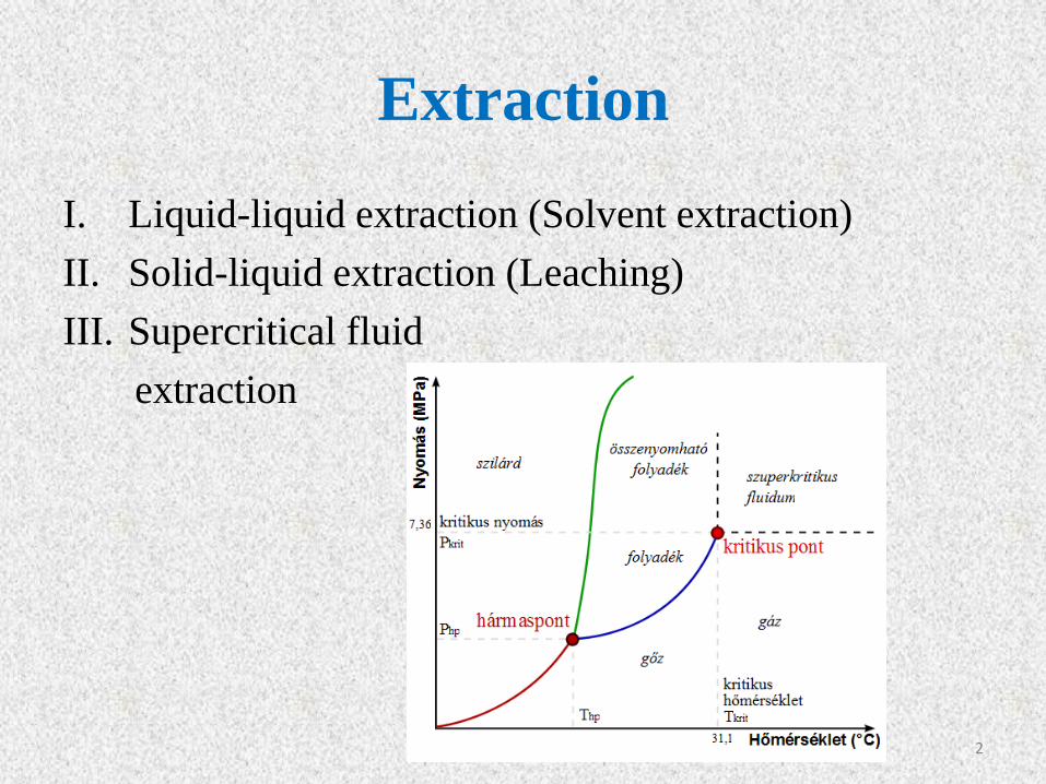
Binary systems
P=constant
Curve: composition of saturated solutions of
the two components.
Area enclosed by the curve: two phase region;
Area outside the curve: mixtures that are
completely miscible.
A, B: composition of the phases in
equilibrium.
Dashed line: tie line.
UCST: Upper Critical Solution Temperature.
LCST: Lower Critical Solution Temperature.
4
Binary systems
Type I.
Type III.
Type II.
Type IV.
P=constant
5
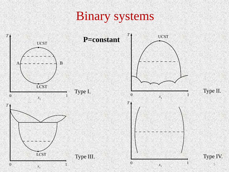
Ternary systems
T=constant
P=constant
A, B, C: pure components.
Curve shown within the triangle: the
boundary of the two phase region.
Ternary solubility curve=binodal
curve.
Dashed line = tie line.
P: plait point (limit of immiscibility).
Type I.: one partially miscible
binary pair.
P
6

Ternary systems
Type II.: two partially miscible binary pairs.
7

III. Single stage extraction (batch extraction)
Theoretically ideal stage: where contact between phases is
sufficiently intimate and maintained for a sufficient period of
time that equilibrium is established.
Equilibrium ratio for a simple ternary system:
y: solute concentration in extract phase (wt%)
x: solute concentration in raffinate phase (wt%)
m: equilibrium ratio (distribution coefficient)
III/1. Simple stirred tank
𝑚 =𝑦
𝑥
Extract phase (E): solvent- rich phase
Raffinate phase (R): solvent-lean phase
http://en.wikipedia.org/wiki/Chemical_reactor 8

9

III/1. Simple stirred tank
Total material balance:
Component balance for solute:
10
𝑚𝑅0 +𝑚𝐸0 = 𝑚𝑅1 +𝑚𝐸1
𝑚𝑅0 ∗ 𝑥0 +𝑚𝐸0 ∗ 𝑦0 = 𝑚𝑅1 ∗ 𝑥1 +𝑚𝐸1 ∗ 𝑦1
𝑚𝑅0: mass of the initial solution (kg)
𝑚𝐸0: mass of the solvent (kg)
𝑚𝑅1: mass of the raffinate (kg)
𝑚𝐸1: mass of the extract (kg)
x, y: concentrations (wt%)

III/1. Simple stirred tank
If the solvent and diluent are immiscible and the concentration of solute is low:
Extraction factor
If y0=0 (neat solvent)
11
𝑓 =𝑚𝐸0
𝑚𝑅0
=𝑚𝐸1
𝑚𝑅1
= 𝑐𝑜𝑛𝑠𝑡𝑎𝑛𝑡
𝑦1 = 𝑚 ∗ 𝑥1 𝑥0 + 𝑓 ∗ 𝑦0 = 𝑥1 + 𝑓 ∗ 𝑦1 = 𝑥1 + 𝑓 ∗ 𝑚 ∗ 𝑥1
𝐸 =𝑚𝐸1 ∗ 𝑦1
𝑚𝑅1 ∗ 𝑥1= 𝑓 ∗ 𝑚
𝑥0 + 𝑓 ∗ 𝑦0 = 𝑥1 ∗ (1 + 𝐸)
𝑥1 =𝑥0
1 + 𝐸+𝐸 ∗ (
𝑦0𝑚)
1 + 𝐸
𝑥1 =𝑥0
1 + 𝐸

III/2. Multiple-extraction
The raffinate from the first stage is extracted with fresh solvent of the same
composition in successive stages.
General solution (if neat solvent is used):
First stage
Second stage
Third stage
nth stage
12
𝑥1 = 𝑥0 ∗1
1 + 𝐸
𝑥2 = 𝑥1 ∗1
1 + 𝐸= 𝑥0 ∗
1
(1 + 𝐸)2
𝑥3 = 𝑥2 ∗1
1 + 𝐸= 𝑥0 ∗
1
(1 + 𝐸)3
𝑥𝑛 = 𝑥0 ∗1
(1 + 𝐸)𝑛
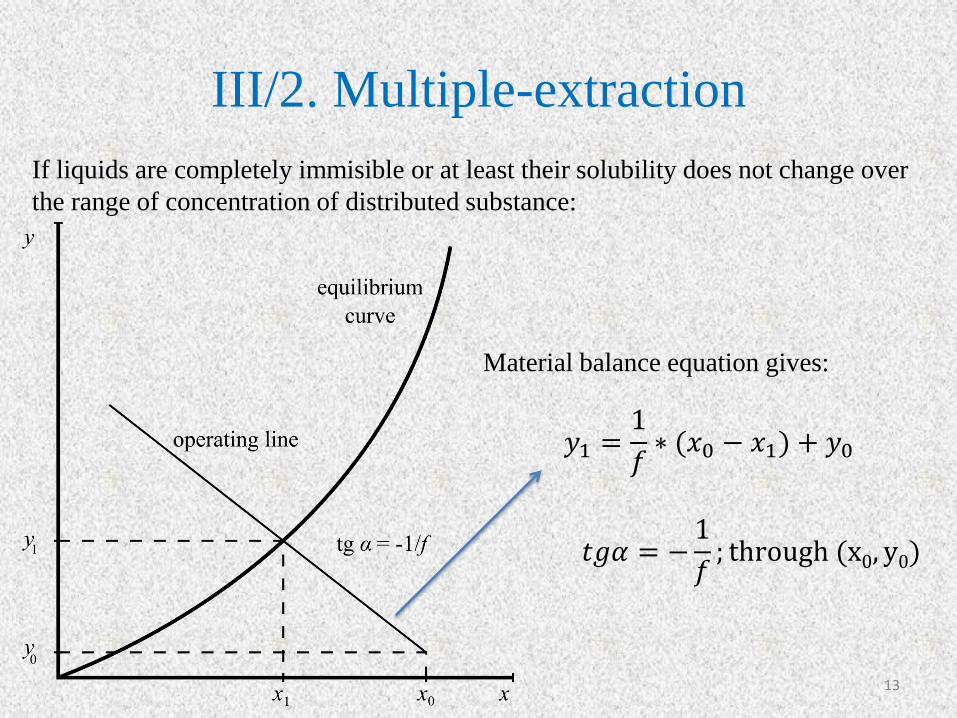
III/2. Multiple-extraction
If liquids are completely immisible or at least their solubility does not change over
the range of concentration of distributed substance:
Material balance equation gives:
13
𝑦1 =1
𝑓∗ (𝑥0 − 𝑥1) + 𝑦0
𝑡𝑔𝛼 = −1
𝑓; through (x0, y0)
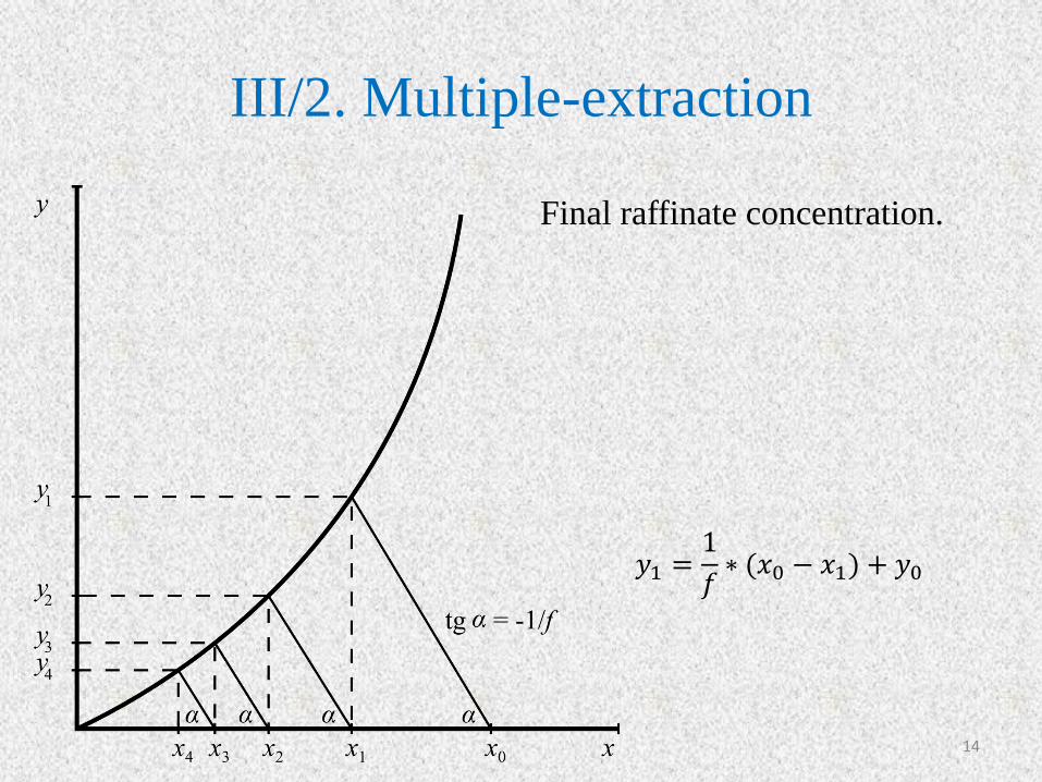
III/2. Multiple-extraction
Final raffinate concentration.
14
𝑦1 =1
𝑓∗ (𝑥0 − 𝑥1) + 𝑦0

III/2. Multiple-extraction Triangular diagram
• If ΄f΄ and ΄m΄ depend on the composition.
Material balance:
xM1 : overall composition of the ternary mixture, M1 point can be located by the lever-arm
rule.
15
𝑚𝑅0 +𝑚𝐸0 = 𝑚𝑅1 +𝑚𝐸1
𝑚𝑅0 ∗ 𝑥0 +𝑚𝐸0 ∗ 𝑦0 = 𝑚𝑅1 ∗ 𝑥1 +𝑚𝐸1 ∗ 𝑦1
𝑥𝑀1=𝑚𝑅0 ∗ 𝑥0 +𝑚𝐸0 ∗ 𝑦0
𝑚𝑅0 +𝑚𝐸0
𝑥𝑀1=𝑚𝑅1 ∗ 𝑥1 +𝑚𝐸1 ∗ 𝑦1
𝑚𝑅1 +𝑚𝐸1
Calculation:

III/2. Multiple-extraction Triangular diagram
16
Methods of calculation.

III/3. Continuous extraction
17
: extract mass flowrate leaving stage n (kg/s)
𝑦𝑛: solute concentration in 𝑚𝐸𝑛 (mass fraction)
: raffinate flowrate leaving stage n (kg/s)
𝑥𝑛: solute concentration in 𝑚𝑅𝑛 (mass fraction)
N: number of equilibrium stages (-)
Enm
Rnm
Rnm0Rm RNm
1EmEnm 1ENm

III/3. Continuous extraction • If the solvent and diluent are completely immiscible and m is constant:
If E=1 Kremser (1930)
• If the solvent and diluent are completely immiscible or at least their solubility does not
change over the range of concentration of distributed substance: McCabe-Thiele
analysis.
18
𝑥𝑁 −𝑦𝑁+1𝑚
𝑥0 −𝑦𝑁+1𝑚
=𝐸 − 1
𝐸𝑁+1 − 1
𝐸 = 𝑓 ∗ 𝑚 𝑒𝑥𝑡𝑟𝑎𝑐𝑡𝑖𝑜𝑛 𝑓𝑟𝑎𝑐𝑡𝑖𝑜𝑛
𝑓 =𝑚𝐸
𝑚𝑅 𝑓𝑙𝑜𝑤𝑟𝑎𝑡𝑒 𝑟𝑎𝑡𝑖𝑜
𝑥𝑁 −𝑦𝑁+1𝑚
𝑥0 −𝑦𝑁+1𝑚
=1
𝑁 + 1
𝑚𝑅 ∗ 𝑥𝑛−1 +𝑚𝐸 ∗ 𝑦𝑁+1 = 𝑚𝑅 ∗ 𝑥𝑁 +𝑚𝐸 ∗ 𝑦𝑛 𝑦𝑛 =1
𝑓∗ (𝑥𝑛−1 − 𝑥𝑁) + 𝑦𝑁+1
Raffinate and extraction rates are constant. Operating line

III/3. Continuous extraction
tgα=1/f; through (xN, yN+1)
Operating line
Equilibrium curve
19
𝑦𝑛 =1
𝑓∗ (𝑥𝑛−1 − 𝑥𝑁) + 𝑦𝑁+1
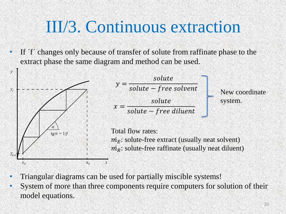
III/3. Continuous extraction
• If ΄f΄ changes only because of transfer of solute from raffinate phase to the
extract phase the same diagram and method can be used.
• Triangular diagrams can be used for partially miscible systems!
• System of more than three components require computers for solution of their
model equations. 20
𝑦 =𝑠𝑜𝑙𝑢𝑡𝑒
𝑠𝑜𝑙𝑢𝑡𝑒 − 𝑓𝑟𝑒𝑒 𝑠𝑜𝑙𝑣𝑒𝑛𝑡
𝑥 =𝑠𝑜𝑙𝑢𝑡𝑒
𝑠𝑜𝑙𝑢𝑡𝑒 − 𝑓𝑟𝑒𝑒 𝑑𝑖𝑙𝑢𝑒𝑛𝑡
Total flow rates:
𝑚𝐸 : solute-free extract (usually neat solvent)
𝑚𝑅 : solute-free raffinate (usually neat diluent)
New coordinate
system.

IV. Selection of solvent in extraction
1. Distribution coefficient (m)
2. Solubility
3. Density (Δρ>150 kg/m3)
4. Interfacial tension
5. Viscosity
6. Chemical reactivity and stability
7. Vapour pressure
8. Flammability
9. Toxicity
10. Cost analysis
The proposed solvent must form a separate phase from the feed solution and
should be able to extract the solute from the feed solution.
21
V. Equipment
1. Mixer-settler or a series of mixer-settlers
2. A column, which may be agitated or pulsed
3. Some other contactor such as a centrifugal device
22
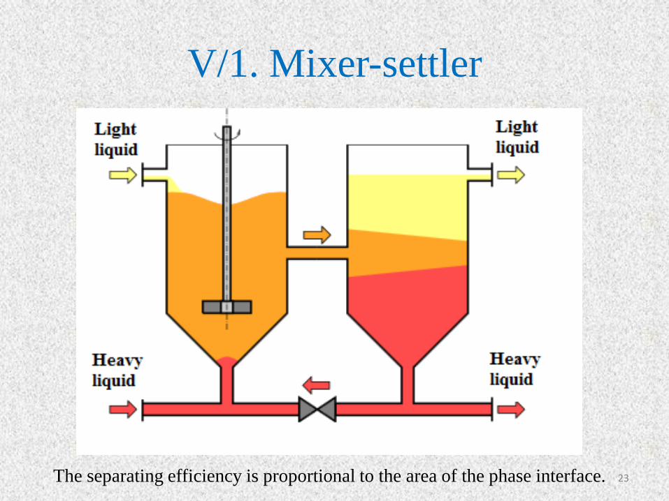
V/1. Mixer-settler
23 The separating efficiency is proportional to the area of the phase interface.

V/1. Mixer-settler cascade
24
Large hold up volumes, long residence time, large physical size.

V/1. Mixer-settler cluster
25

V/1. Copper’s extraction in Mixer-
settler
26
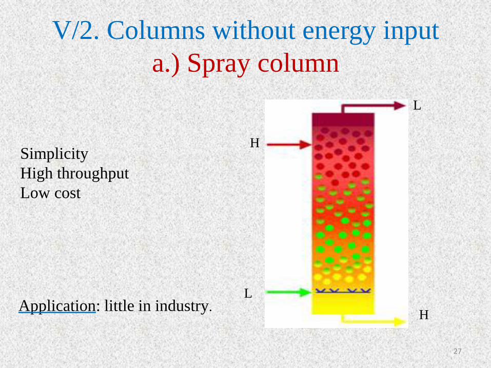
V/2. Columns without energy input
a.) Spray column
L
H
H
L
27
Simplicity
High throughput
Low cost
Application: little in industry.

b.) Packet columns
28
• The most purposes random packing;
• The packing should be wetted by the
continuous phase.
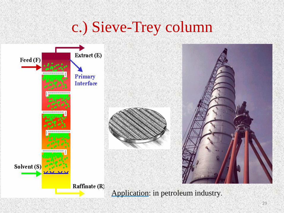
c.) Sieve-Trey column
29
Application: in petroleum industry.

V/3. Columns with energy input
a.) Rotating Disc Contactor (RDC)
Shell
1948
30
Application: in petroleum and
chemical industries, waste water
treatment.

b.) Oldshue-Rushton column (1952,
USA)
http://www.separationprocesses.com/Extraction/SE_Chp03c.htm 31
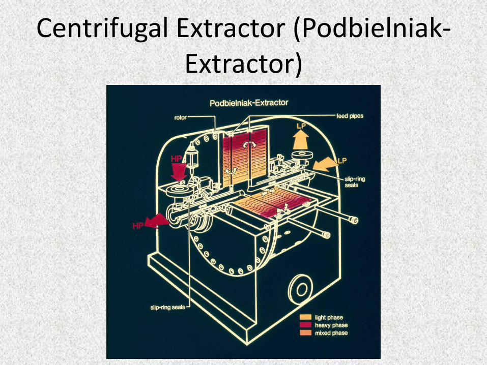
Centrifugal Extractor (Podbielniak-Extractor)

33
Centrifugal extractor (Podbielniak-Extractor)

34
Karr column

35
Karr column

Thank you for your attention!
36