Extraction Chemical Unit Operations II. Béla Simándi, Edit Székely Department of Chemical and Environmental Process Engineering

Welcome message from author
This document is posted to help you gain knowledge. Please leave a comment to let me know what you think about it! Share it to your friends and learn new things together.
Transcript

Extraction Chemical Unit Operations II.
Béla Simándi, Edit Székely
Department of Chemical and Environmental Process Engineering
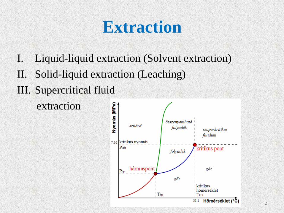
Extraction
I. Liquid-liquid extraction (Solvent extraction)
II. Solid-liquid extraction (Leaching)
III. Supercritical fluid
extraction
2

Liquid-liquid extraction I. Applications
1. Hydrometallurgy
2. Inorganic processes
3. Petroleum industry
4. Pharmaceuticals
5. Waste waters
3

II. Liquid-liquid equilibrium
Binary systems
P=constant
Curve: composition of saturated solutions of
the two components.
Area enclosed by the curve: two phase region;
Area outside the curve: mixtures that are
completely miscible.
A, B: composition of the phases in
equilibrium.
Dashed line: tie line.
UCST: Upper Critical Solution Temperature.
LCST: Lower Critical Solution Temperature.
4
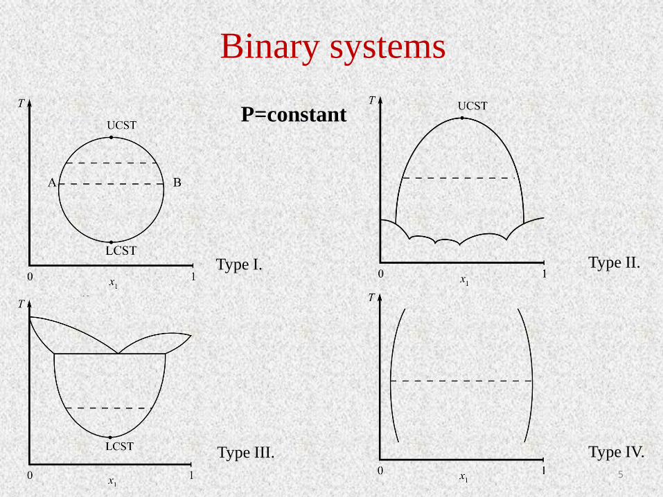
Binary systems
Type I.
Type III.
Type II.
Type IV.
P=constant
5
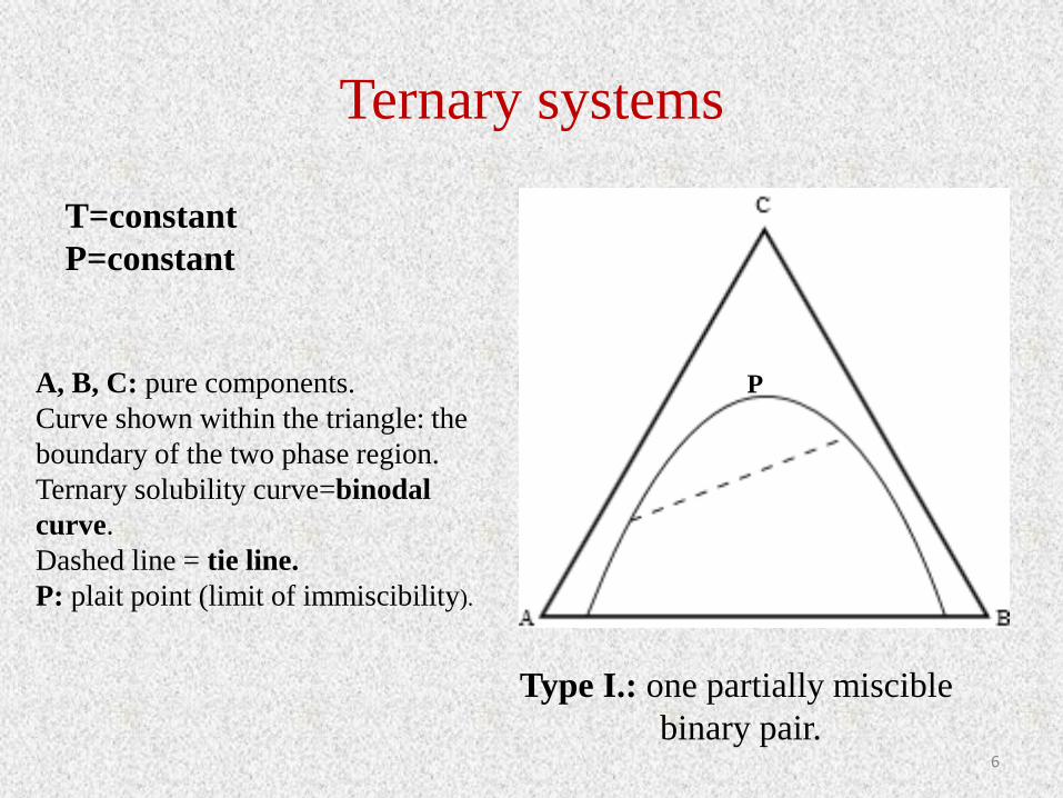
Ternary systems
T=constant
P=constant
A, B, C: pure components.
Curve shown within the triangle: the
boundary of the two phase region.
Ternary solubility curve=binodal
curve.
Dashed line = tie line.
P: plait point (limit of immiscibility).
Type I.: one partially miscible
binary pair.
P
6

Ternary systems
Type II.: two partially miscible binary pairs.
7

III. Single stage extraction (batch extraction)
Theoretically ideal stage: where contact between phases is
sufficiently intimate and maintained for a sufficient period of
time that equilibrium is established.
Equilibrium ratio for a simple ternary system:
y: solute concentration in extract phase (wt%)
x: solute concentration in raffinate phase (wt%)
m: equilibrium ratio (distribution coefficient)
III/1. Simple stirred tank
𝑚 =𝑦
𝑥
Extract phase (E): solvent- rich phase
Raffinate phase (R): solvent-lean phase
http://en.wikipedia.org/wiki/Chemical_reactor 8

9

III/1. Simple stirred tank
Total material balance:
Component balance for solute:
10
𝑚𝑅0 +𝑚𝐸0 = 𝑚𝑅1 +𝑚𝐸1
𝑚𝑅0 ∗ 𝑥0 +𝑚𝐸0 ∗ 𝑦0 = 𝑚𝑅1 ∗ 𝑥1 +𝑚𝐸1 ∗ 𝑦1
𝑚𝑅0: mass of the initial solution (kg)
𝑚𝐸0: mass of the solvent (kg)
𝑚𝑅1: mass of the raffinate (kg)
𝑚𝐸1: mass of the extract (kg)
x, y: concentrations (wt%)

III/1. Simple stirred tank
If the solvent and diluent are immiscible and the concentration of solute is low:
Extraction factor
If y0=0 (neat solvent)
11
𝑓 =𝑚𝐸0
𝑚𝑅0
=𝑚𝐸1
𝑚𝑅1
= 𝑐𝑜𝑛𝑠𝑡𝑎𝑛𝑡
𝑦1 = 𝑚 ∗ 𝑥1 𝑥0 + 𝑓 ∗ 𝑦0 = 𝑥1 + 𝑓 ∗ 𝑦1 = 𝑥1 + 𝑓 ∗ 𝑚 ∗ 𝑥1
𝐸 =𝑚𝐸1 ∗ 𝑦1
𝑚𝑅1 ∗ 𝑥1= 𝑓 ∗ 𝑚
𝑥0 + 𝑓 ∗ 𝑦0 = 𝑥1 ∗ (1 + 𝐸)
𝑥1 =𝑥0
1 + 𝐸+𝐸 ∗ (
𝑦0𝑚)
1 + 𝐸
𝑥1 =𝑥0
1 + 𝐸

III/2. Multiple-extraction
The raffinate from the first stage is extracted with fresh solvent of the same
composition in successive stages.
General solution (if neat solvent is used):
First stage
Second stage
Third stage
nth stage
12
𝑥1 = 𝑥0 ∗1
1 + 𝐸
𝑥2 = 𝑥1 ∗1
1 + 𝐸= 𝑥0 ∗
1
(1 + 𝐸)2
𝑥3 = 𝑥2 ∗1
1 + 𝐸= 𝑥0 ∗
1
(1 + 𝐸)3
𝑥𝑛 = 𝑥0 ∗1
(1 + 𝐸)𝑛
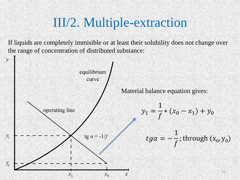
III/2. Multiple-extraction
If liquids are completely immisible or at least their solubility does not change over
the range of concentration of distributed substance:
Material balance equation gives:
13
𝑦1 =1
𝑓∗ (𝑥0 − 𝑥1) + 𝑦0
𝑡𝑔𝛼 = −1
𝑓; through (x0, y0)
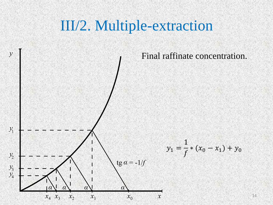
III/2. Multiple-extraction
Final raffinate concentration.
14
𝑦1 =1
𝑓∗ (𝑥0 − 𝑥1) + 𝑦0

III/2. Multiple-extraction Triangular diagram
• If ΄f΄ and ΄m΄ depend on the composition.
Material balance:
xM1 : overall composition of the ternary mixture, M1 point can be located by the lever-arm
rule.
15
𝑚𝑅0 +𝑚𝐸0 = 𝑚𝑅1 +𝑚𝐸1
𝑚𝑅0 ∗ 𝑥0 +𝑚𝐸0 ∗ 𝑦0 = 𝑚𝑅1 ∗ 𝑥1 +𝑚𝐸1 ∗ 𝑦1
𝑥𝑀1=𝑚𝑅0 ∗ 𝑥0 +𝑚𝐸0 ∗ 𝑦0
𝑚𝑅0 +𝑚𝐸0
𝑥𝑀1=𝑚𝑅1 ∗ 𝑥1 +𝑚𝐸1 ∗ 𝑦1
𝑚𝑅1 +𝑚𝐸1
Calculation:

III/2. Multiple-extraction Triangular diagram
16
Methods of calculation.

III/3. Continuous extraction
17
: extract mass flowrate leaving stage n (kg/s)
𝑦𝑛: solute concentration in 𝑚𝐸𝑛 (mass fraction)
: raffinate flowrate leaving stage n (kg/s)
𝑥𝑛: solute concentration in 𝑚𝑅𝑛 (mass fraction)
N: number of equilibrium stages (-)
Enm
Rnm
Rnm0Rm RNm
1EmEnm 1ENm

III/3. Continuous extraction • If the solvent and diluent are completely immiscible and m is constant:
If E=1 Kremser (1930)
• If the solvent and diluent are completely immiscible or at least their solubility does not
change over the range of concentration of distributed substance: McCabe-Thiele
analysis.
18
𝑥𝑁 −𝑦𝑁+1𝑚
𝑥0 −𝑦𝑁+1𝑚
=𝐸 − 1
𝐸𝑁+1 − 1
𝐸 = 𝑓 ∗ 𝑚 𝑒𝑥𝑡𝑟𝑎𝑐𝑡𝑖𝑜𝑛 𝑓𝑟𝑎𝑐𝑡𝑖𝑜𝑛
𝑓 =𝑚𝐸
𝑚𝑅 𝑓𝑙𝑜𝑤𝑟𝑎𝑡𝑒 𝑟𝑎𝑡𝑖𝑜
𝑥𝑁 −𝑦𝑁+1𝑚
𝑥0 −𝑦𝑁+1𝑚
=1
𝑁 + 1
𝑚𝑅 ∗ 𝑥𝑛−1 +𝑚𝐸 ∗ 𝑦𝑁+1 = 𝑚𝑅 ∗ 𝑥𝑁 +𝑚𝐸 ∗ 𝑦𝑛 𝑦𝑛 =1
𝑓∗ (𝑥𝑛−1 − 𝑥𝑁) + 𝑦𝑁+1
Raffinate and extraction rates are constant. Operating line

III/3. Continuous extraction
tgα=1/f; through (xN, yN+1)
Operating line
Equilibrium curve
19
𝑦𝑛 =1
𝑓∗ (𝑥𝑛−1 − 𝑥𝑁) + 𝑦𝑁+1
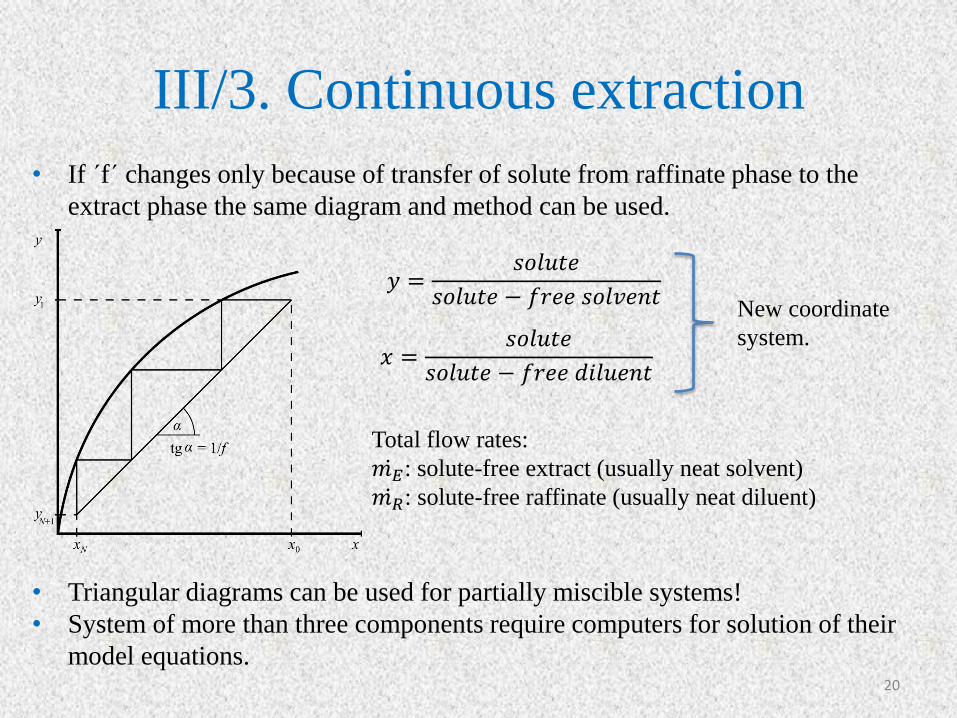
III/3. Continuous extraction
• If ΄f΄ changes only because of transfer of solute from raffinate phase to the
extract phase the same diagram and method can be used.
• Triangular diagrams can be used for partially miscible systems!
• System of more than three components require computers for solution of their
model equations. 20
𝑦 =𝑠𝑜𝑙𝑢𝑡𝑒
𝑠𝑜𝑙𝑢𝑡𝑒 − 𝑓𝑟𝑒𝑒 𝑠𝑜𝑙𝑣𝑒𝑛𝑡
𝑥 =𝑠𝑜𝑙𝑢𝑡𝑒
𝑠𝑜𝑙𝑢𝑡𝑒 − 𝑓𝑟𝑒𝑒 𝑑𝑖𝑙𝑢𝑒𝑛𝑡
Total flow rates:
𝑚𝐸 : solute-free extract (usually neat solvent)
𝑚𝑅 : solute-free raffinate (usually neat diluent)
New coordinate
system.

IV. Selection of solvent in extraction
1. Distribution coefficient (m)
2. Solubility
3. Density (Δρ>150 kg/m3)
4. Interfacial tension
5. Viscosity
6. Chemical reactivity and stability
7. Vapour pressure
8. Flammability
9. Toxicity
10. Cost analysis
The proposed solvent must form a separate phase from the feed solution and
should be able to extract the solute from the feed solution.
21
V. Equipment
1. Mixer-settler or a series of mixer-settlers
2. A column, which may be agitated or pulsed
3. Some other contactor such as a centrifugal device
22
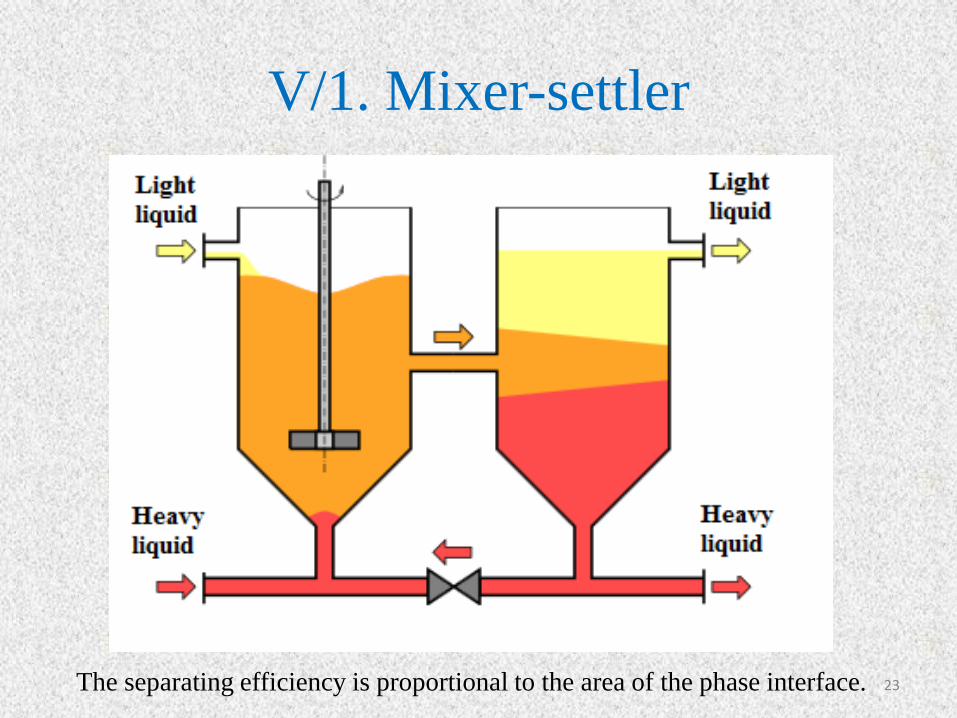
V/1. Mixer-settler
23 The separating efficiency is proportional to the area of the phase interface.

V/1. Mixer-settler cascade
24
Large hold up volumes, long residence time, large physical size.

V/1. Mixer-settler cluster
25

V/1. Copper’s extraction in Mixer-
settler
26
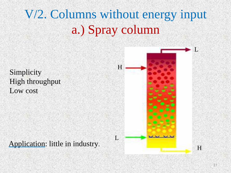
V/2. Columns without energy input
a.) Spray column
L
H
H
L
27
Simplicity
High throughput
Low cost
Application: little in industry.

b.) Packet columns
28
• The most purposes random packing;
• The packing should be wetted by the
continuous phase.
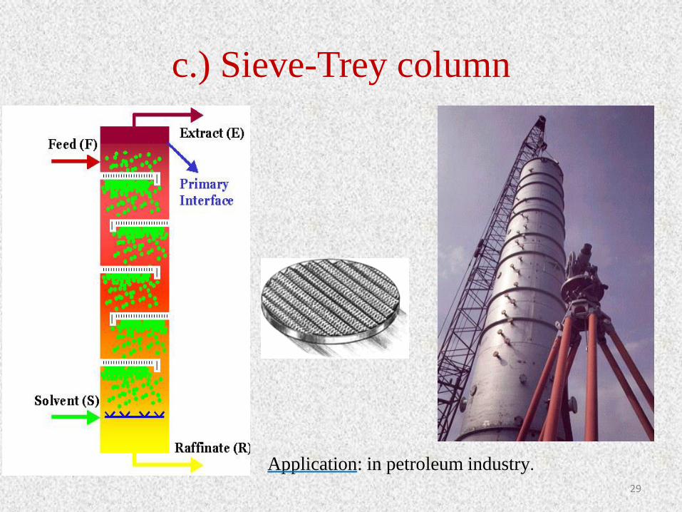
c.) Sieve-Trey column
29
Application: in petroleum industry.

V/3. Columns with energy input
a.) Rotating Disc Contactor (RDC)
Shell
1948
30
Application: in petroleum and
chemical industries, waste water
treatment.

b.) Oldshue-Rushton column (1952,
USA)
http://www.separationprocesses.com/Extraction/SE_Chp03c.htm 31
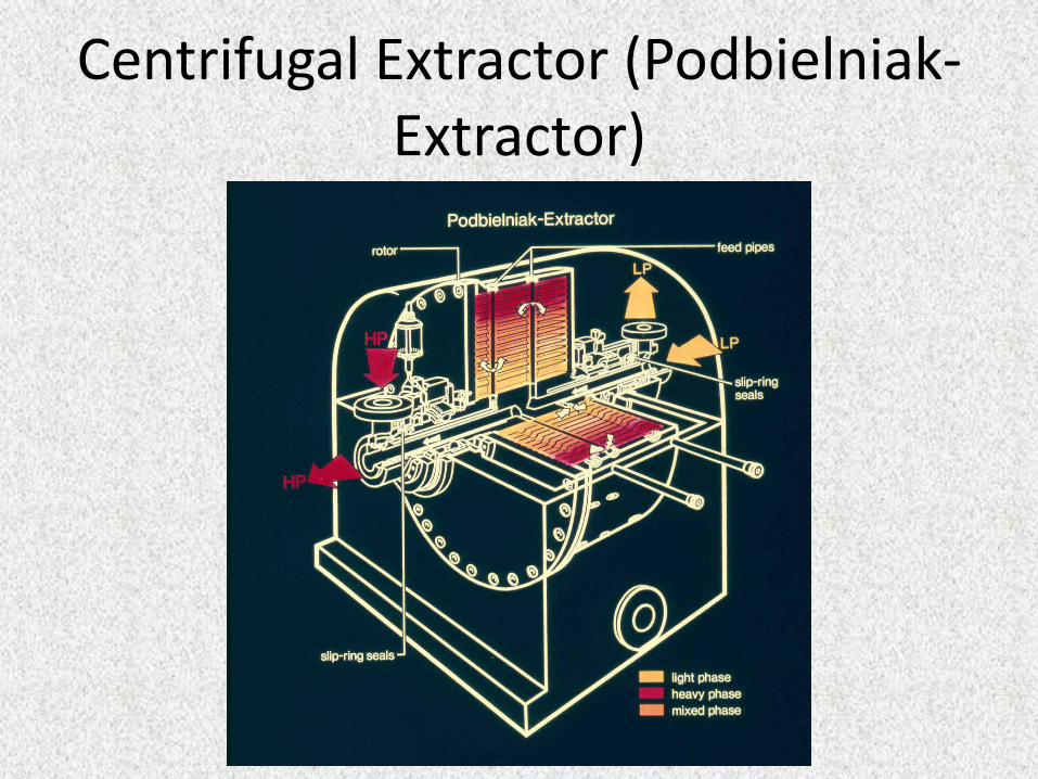
Centrifugal Extractor (Podbielniak-Extractor)

33
Centrifugal extractor (Podbielniak-Extractor)

34
Karr column

35
Karr column

Thank you for your attention!
36
Related Documents