1
SKEE2263
Digital Systems Week 1: Introduction

2
This course is about digital logic design.
You should be well versed in:
› Data and number representation and operations
› Boolean algebra
› Logic gates
› Simple minimization techniques (up to 4-variable Karnaugh
maps)
All these topics you’d learnt in SEE 1223.
Why this course?

3
Fundamental digital design skills (data types, Boolean
algebra, minimization techniques)
Combinational circuits (circuits without memory)
Introduction to arithmetic circuitry
Sequential circuits (circuits with memory)
Finite/Algorithmic State Machines. Some case studies.
Major Topics To Be Discussed

4
Weekly Schedule
Week Topic
1 Topic 1: Introduction
Overview of digital system design, introduction to design CADs.
Review on digital logic techniques, MSI circuits (mux, decoder,
counter), timing issues (combinational delay)
2-3 Topic 2: Multi-variable Logic
Entered-Variable K-Map, MSI implementations. Logic simplification
tools
4 Topic 3: Alternative Logic implementations
Random-access memory and read-only memory (RAM/ROM),
programmable logic array and programmable array logic
(PLA/PAL), and complex programmable logic device, and field-
programmable gate array (CPLD/FPGA).
5 Topic 4: Number Systems
Fixed-point (including Q number format), floating-point (single-
precision IEEE), quantization, scaling and word size
5
Weekly Schedule
Week Topic
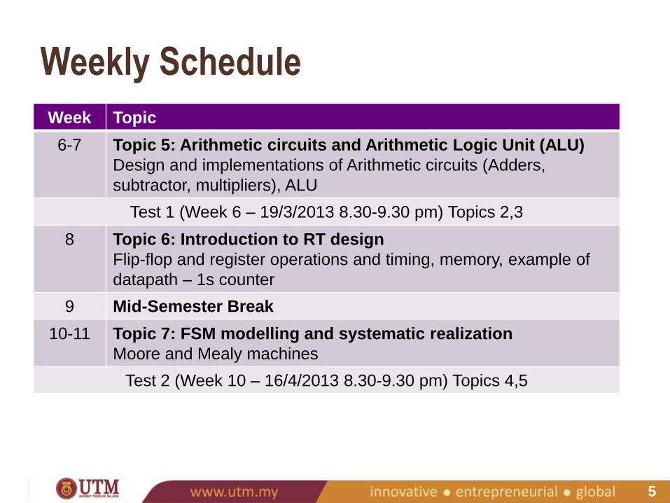
6-7 Topic 5: Arithmetic circuits and Arithmetic Logic Unit (ALU)
Design and implementations of Arithmetic circuits (Adders,
subtractor, multipliers), ALU
Test 1 (Week 6 – 19/3/2013 8.30-9.30 pm) Topics 2,3
8 Topic 6: Introduction to RT design
Flip-flop and register operations and timing, memory, example of
datapath – 1s counter
9 Mid-Semester Break
10-11 Topic 7: FSM modelling and systematic realization
Moore and Mealy machines
Test 2 (Week 10 – 16/4/2013 8.30-9.30 pm) Topics 4,5

6
Weekly Schedule
Week Topic
12 Topic 8: FSM modelling and analysis case studies
Case studies, implementation issues
13 Topic 9: FSM Implementation Alternatives
One hot, D to JK, T, counter-based FSM
14-15 Topic 10: RT System Design
Algorithmic State Machines (ASM), DU and CU as parts of RT
System Design, timing issues revisited
Test 3 (Week 14 – 14/5/2013 8.30-9.30 pm) Topics 6-9
16 Revision Week
17-19 Final Examination
7
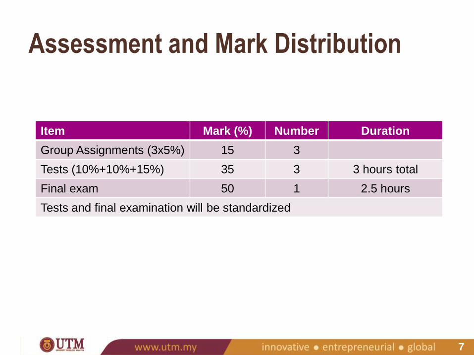
Item Mark (%) Number Duration
Group Assignments (3x5%) 15 3
Tests (10%+10%+15%) 35 3 3 hours total
Final exam 50 1 2.5 hours
Tests and final examination will be standardized
Assessment and Mark Distribution

8
Textbook:
› Randy H. Katz and Gaetano Borriello, Contemporary Logic
Design. 2nd ed. Pearson Education, 2006.
Other references
› Stephen Brown and Zvonko Vranesic, Fundamentals of Digital
Logic with VHDL Design. 2nd ed. McGraw-Hill, 2005.
› Donald D. Givone, Digital Principles and Design, McGraw-Hill,
2003.
› Alan B. Marcovitz, Introduction to Logic Design. 2nd ed.
McGraw-Hill, 2005.
Book(s)

9
Exercises, for you to do on your own
Usage of Quartus II CAD
› We will use Quartus II - won’t be taught in class.
› Familiarize yourself with this EDA.
› You have to learn it yourself. Tutorials will be given to assist
you.
› Lecture notes will be made available at UTM E-Learning Server
<http://elearning.utm.my>
What you can expect

10
Why Digital
System Design?
11
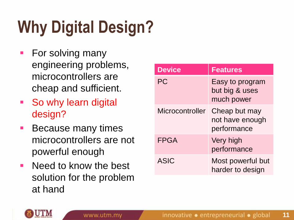
For solving many
engineering problems,
microcontrollers are
cheap and sufficient.
So why learn digital
design?
Because many times
microcontrollers are not
powerful enough
Need to know the best
solution for the problem
at hand
Device Features
PC Easy to program
but big & uses
much power
Microcontroller Cheap but may
not have enough
performance
FPGA Very high
performance
ASIC Most powerful but
harder to design
Why Digital Design?

12
Application-Specific Integrated Circuit
A custom-made chip
Take a lot of engineering effort to design but for some
applications, it’s worth the trouble
Microprocessors & microcontrollers must be ASIC to
squeeze maximum performance & lowest power
In Malaysia, ASIC design is done in Intel, Altera,
Silterra…
Must be good in VLSI design… a job for SKEL
graduates
So what if you’re not SKEL?
ASIC

13
Field-Programmable Gate Array
Programmable hardware
A blank chip is programmed to implement logic functions
FPGA is mainly used to accelerate certain operations which
are too slow on microcontrollers yet want to maintain small
size & low power
› Remember, PC is also powerful but big & power-hungry
Programming is by schematic diagram or HDL (hardware
description language) and downloaded into the chip
Much easier than ASIC design
Top two FPGA companies are Xilinx and Altera
We use Altera in UTM. You’ll need to use Altera Quartus
software to program these chips
FPGA
14
Robotics & Control:
› Can control robots using image processing
› Can design more stable controllers
Instrumentation:
› Can increase the number of samples per second
› Can increase accuracy of measurements
Communications:
› Can process more data packets per second
› Can implement software-defined radio
Power:
› Can control a motor more precisely at lower power consumption
› Can design more efficient & greener energy sources
FPGA is very useful in…

15
A single-purpose
computer built into a
larger system for the
purposes of controlling
and monitoring the
system
Nearly any computing
system other than a
desktop computer
Embedded Systems

16
System-on-Chip (SoC) is a complex IC that integrates
the major functions of a complete end-product into a
single chip or chipset
May be ASIC or FPGA
Most Embedded Systems are SoC

17
SoC in Smartphones
Which one do you
have?
18
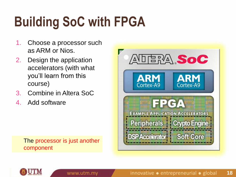
1. Choose a processor such
as ARM or Nios.
2. Design the application
accelerators (with what
you’ll learn from this
course)
3. Combine in Altera SoC
4. Add software
Building SoC with FPGA
The processor is just another
component

19
Apps
OS
System
Sub-system
MSI
Gates
Transistors
Device
Layout
Level Examples Relevant Course,
UTM
Tools
App Games, browser Software Engineering C/C++/Java
Compilers
OS iOS, Android, Linux Computer System C Compiler
System iPhone,
Samsung Galaxy
CAD,
Computer System
C Compiler,
Quartus HDL
Sub-system
(cores)
USB controller, LCD
driver, processor
CAD,
Digital systems
Quartus HDL,
Quartus schematic
Register Flip-flop, register,
counter, decoder
CAD,
Digital systems,
Digital electronics
Quartus schematic
Gates AND, OR, NOT Digital electronics,
VLSI
Quartus schematic,
Tanner
Transistor PNP, NPN VLSI Tanner
Silicon
Layout
Metal, oxide, poly VLSI Tanner
Digital Systems as Layers (Smartphone)
20
Engineers may be required to solve problems using
embedded systems
Many solutions exist but there is no one-size-fits-all
Designing high performance embedded systems require
knowledge in digital systems design
Simple digital circuits may be designed using
schematics but very complex systems require writing
code in hardware description language (HDL)
You also need to know software design, but that is
covered elsewhere
Summary
21
Overview of
Digital System
Design
22
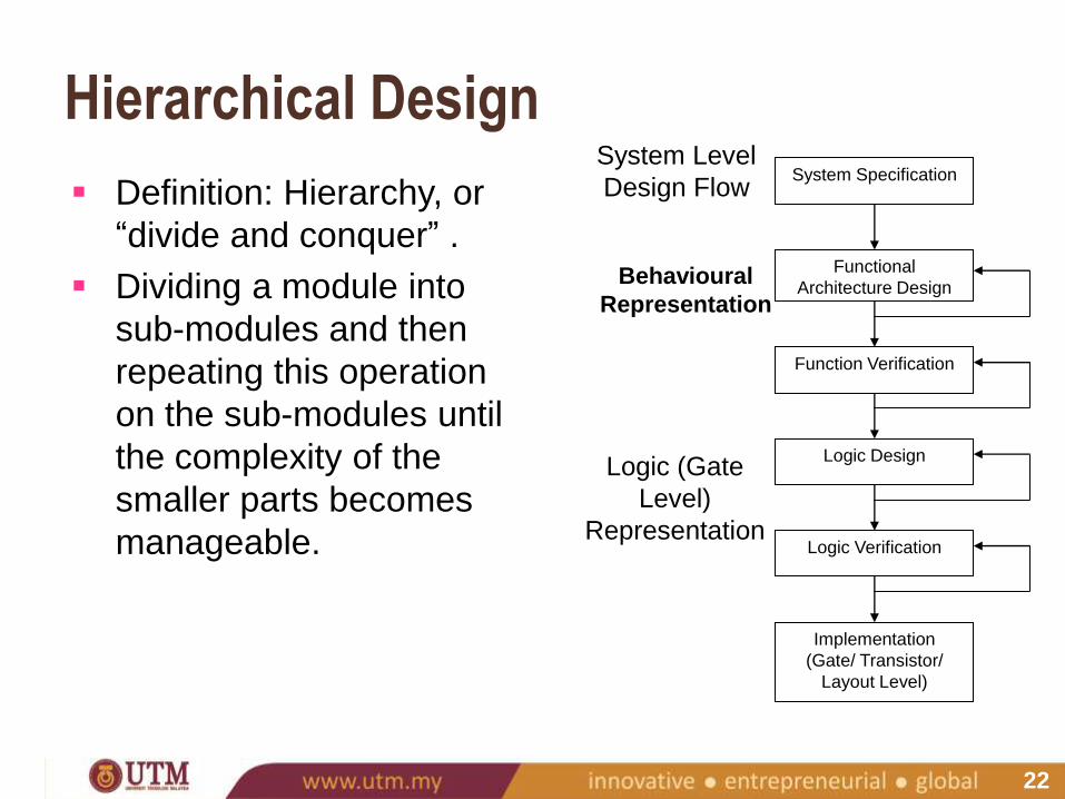
Definition: Hierarchy, or
“divide and conquer” .
Dividing a module into
sub-modules and then
repeating this operation
on the sub-modules until
the complexity of the
smaller parts becomes
manageable.
Hierarchical Design System Specification
Functional
Architecture Design
Function Verification
Logic Design
Logic Verification
Implementation
(Gate/ Transistor/
Layout Level)
System Level
Design Flow
Behavioural
Representation
Logic (Gate
Level)
Representation
23
Top-down design flow provides an excellent design
process control.
In reality, there is no truly unidirectional approach.
Both top-down and bottom-up approaches have to be
combined. In system level design, in order to fit the
system into the allowable constraint (area, speed,
power consumption) some functions may have to be
removed and the design process must be repeated
(may require significant modifications).
Top-down vs Bottom-up

24
Development Process Required product
Design specifications
Initial design
Simulation
Design correct?
Redesign
Prototype implementation
Testing
Meets specifications?
Finished product
Minor errors?
Make corrections
No
Yes
No
Yes
Yes
No
25
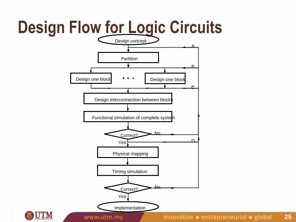
Design Flow for Logic Circuits
Design interconnection between blocks
Functional simulation of complete system
Correct?
Physical mapping
Timing simulation
Correct?
Implementation
No
Yes
No
Yes
Design one block Design one block
Partition
Design concept A
B
C
D

26
Regularity
› Means that the hierarchical decomposition of a large system
must be simple and similar as much as possible. It must exists
at all levels of abstraction.
› Eg: At the logic level, identical gate structures can be used, etc.
If the designer has a small library of well-defined and well-
characterized basic building blocks, a number of different
functions can be constructed by using this principle.
Regularity, Modularity and Locality
27
Modularity
› Hierarchical functional blocks must be well-defined –
functionality and interfaces.
› Each block can be designed independently (relatively from each
other).
› All of the blocks can be combined with ease to form the large
system.
› Enables the parallelization of the design process.
Regularity, Modularity and Locality

28
Locality
› The well-characterized definition of interfaces for each module
in the system stays at the local level.
› Thus, the internals of each module become unimportant to the
exterior modules.
› Connections are mostly between neighbouring modules,
avoiding long-distance connections as much as possible to
avoid interconnect delay. Time-critical operations should be
performed locally.
Regularity, Modularity and Locality