Please also note the information on the last page
IO-Link Interface Description
KQ1000KQ1001
IOD
D-P
DF
Cre
ator
V 2
.0.0
.84
ifm-0
0039
C-2
0190
806-
IOD
D1.
1, V
1.3.
14.2
9C
opyr
ight
201
9, B
uild
er: 4
.4.3
.1, T
ime:
06:
57:4
4
2/22
Table of Contents
1 Device variant ................................................................................ 3
2 Communication ................................................................................ 4
3 Parameter overview ................................................................................ 5
4 System Commands ................................................................................ 8
5 Identification ................................................................................ 9
6 Observation ................................................................................ 10
6.1 Process Data Input/Output ................................................................................ 10
7 Parameter ................................................................................ 11
7.1 Application Setup ................................................................................ 11
7.2 Output configuration ................................................................................ 11
7.3 Digital output 1 ................................................................................ 12
7.4 Digital output 2 ................................................................................ 12
7.5 Digital output 3 ................................................................................ 13
7.6 Fault Configuration ................................................................................ 14
7.7 Counter configuration ................................................................................ 14
7.8 Damping ................................................................................ 15
7.9 Setting of the sensor display ................................................................................ 15
7.10 Memory ................................................................................ 15
7.11 Setup ................................................................................ 16
8 Diagnosis ................................................................................ 17
8.1 Diagnosis ................................................................................ 17
9 Events ................................................................................ 20
10 Error types ................................................................................ 21
3/22
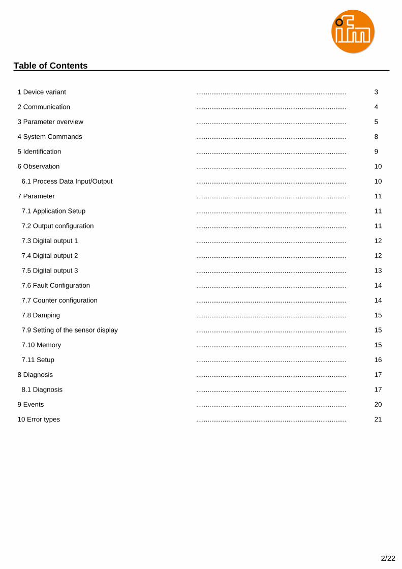
1 Device variant
KQ1000
Capacitive level sensor
KQ1001
Capacitive level sensor
4/22
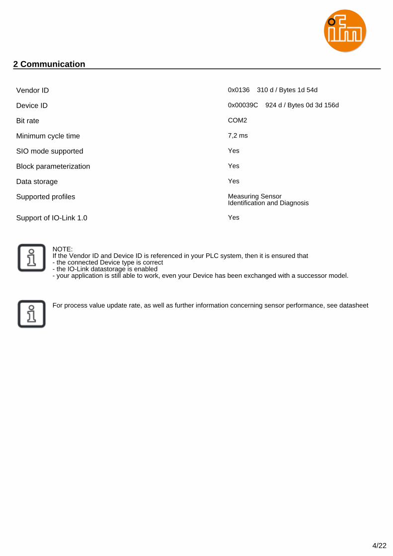
2 Communication
Vendor ID 0x0136 310 d / Bytes 1d 54d
Device ID 0x00039C 924 d / Bytes 0d 3d 156d
Bit rate COM2
Minimum cycle time 7,2 ms
SIO mode supported Yes
Block parameterization Yes
Data storage Yes
Supported profiles Measuring SensorIdentification and Diagnosis
Support of IO-Link 1.0 Yes
NOTE:If the Vendor ID and Device ID is referenced in your PLC system, then it is ensured that- the connected Device type is correct- the IO-Link datastorage is enabled- your application is still able to work, even your Device has been exchanged with a successor model.
For process value update rate, as well as further information concerning sensor performance, see datasheet
5/22
3 Parameter overview
Parameter Index Subindex Type Factory settingDevice Access Locks 12 RecordT (16 Bit) false
Vendor name 16 StringT (19 Byte) ifm electronic gmbh
Vendor text 17 StringT (11 Byte) www.ifm.com
Product Name 18 StringT (6 Byte)
Product ID 19 StringT (6 Byte)
Product Text 20 StringT (23 Byte) Capacitive Level Sensor
Serial Number 21 StringT (16 Byte)
Hardware Version 22 StringT (8 Byte)
Firmware Version 23 StringT (8 Byte)
Application Specific Tag 24 StringT (32 Byte) ***
Function Tag 25 StringT (32 Byte) ***
Location Tag 26 StringT (32 Byte) ***
Device Status 36 UIntegerT (8 Bit) 0 (Device is OK)
Detailed Device Status 37 OctetStringT (3 byte) [10] 0x00,0x00,0x00
Process data input 40 RecordT (32 Bit)
OUT1 Counter 350 IntegerT (32 Bit) 0
OUT2 Counter 351 IntegerT (32 Bit) 0
OUT3 Counter 352 IntegerT (32 Bit) 0
P-n 500 UIntegerT (8 Bit) 0 (PnP)
dAP 510 UIntegerT (16 Bit) 0
dFo 530 UIntegerT (16 Bit) 1
FOU1 531 UIntegerT (8 Bit) 1 (OU)
FOU2 532 UIntegerT (8 Bit) 1 (OU)
FOU3 533 UIntegerT (8 Bit) 1 (OU)
Power cycles 541 IntegerT (32 Bit) 0
Operating hours 542 IntegerT (32 Bit) 0
Internal temperature 543 IntegerT (16 Bit)
Internal_Temperature_HiLo 544 RecordT (32 Bit)
Lo 544 1 IntegerT (16 Bit)
Hi 544 2 IntegerT (16 Bit)
Active Events 545 RecordT (32 Bit)
Param configuration fault 546 UIntegerT (32 Bit) [10] 0 (OK)
Hi 560 IntegerT (16 Bit)
Lo 561 IntegerT (16 Bit)
ou1 580 UIntegerT (8 Bit) 3 (Hno / Hysteresis fct normally open)
dS1 581 UIntegerT (16 Bit) 0
dr1 582 UIntegerT (16 Bit) 0
SP1 (FH1) 583 IntegerT (16 Bit) 25
rP1 (FL1) 584 IntegerT (16 Bit) 20
ou2 590 UIntegerT (8 Bit) 16 (OFF / Output Off)
dS2 591 UIntegerT (16 Bit) 0
dr2 592 UIntegerT (16 Bit) 0
SP2 (FH2) 593 IntegerT (16 Bit) 50
rP2 (FL2) 594 IntegerT (16 Bit) 45
ou3 600 UIntegerT (8 Bit) 16 (OFF / Output Off)
6/22
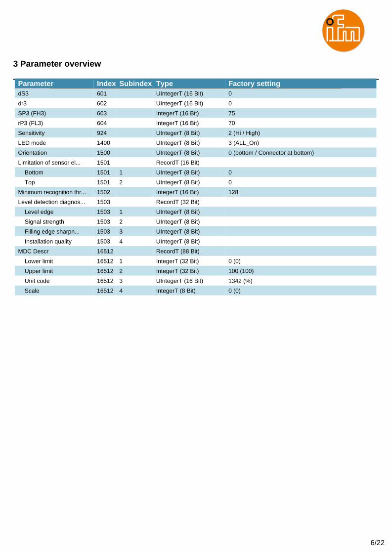
3 Parameter overview
Parameter Index Subindex Type Factory settingdS3 601 UIntegerT (16 Bit) 0
dr3 602 UIntegerT (16 Bit) 0
SP3 (FH3) 603 IntegerT (16 Bit) 75
rP3 (FL3) 604 IntegerT (16 Bit) 70
Sensitivity 924 UIntegerT (8 Bit) 2 (Hi / High)
LED mode 1400 UIntegerT (8 Bit) 3 (ALL_On)
Orientation 1500 UIntegerT (8 Bit) 0 (bottom / Connector at bottom)
Limitation of sensor el... 1501 RecordT (16 Bit)
Bottom 1501 1 UIntegerT (8 Bit) 0
Top 1501 2 UIntegerT (8 Bit) 0
Minimum recognition thr... 1502 IntegerT (16 Bit) 128
Level detection diagnos... 1503 RecordT (32 Bit)
Level edge 1503 1 UIntegerT (8 Bit)
Signal strength 1503 2 UIntegerT (8 Bit)
Filling edge sharpn... 1503 3 UIntegerT (8 Bit)
Installation quality 1503 4 UIntegerT (8 Bit)
MDC Descr 16512 RecordT (88 Bit)
Lower limit 16512 1 IntegerT (32 Bit) 0 (0)
Upper limit 16512 2 IntegerT (32 Bit) 100 (100)
Unit code 16512 3 UIntegerT (16 Bit) 1342 (%)
Scale 16512 4 IntegerT (8 Bit) 0 (0)
7/22
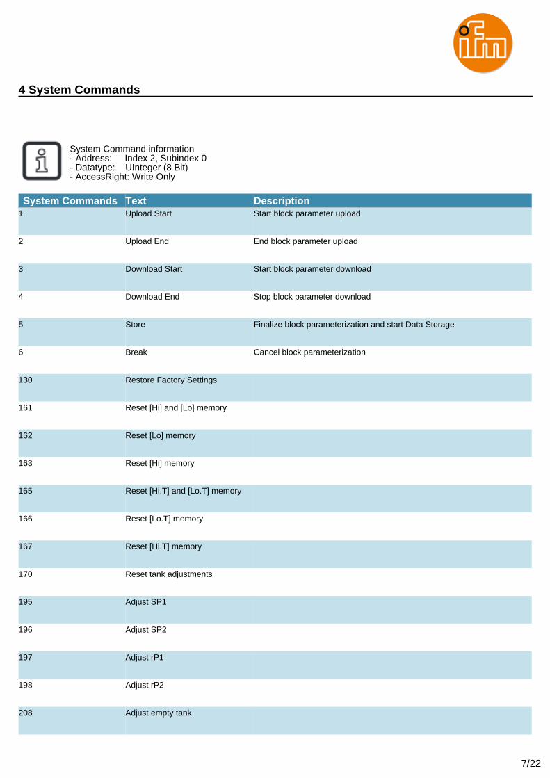
4 System Commands
System Command information- Address: Index 2, Subindex 0- Datatype: UInteger (8 Bit)- AccessRight: Write Only
System Commands Text Description1 Upload Start Start block parameter upload
2 Upload End End block parameter upload
3 Download Start Start block parameter download
4 Download End Stop block parameter download
5 Store Finalize block parameterization and start Data Storage
6 Break Cancel block parameterization
130 Restore Factory Settings
161 Reset [Hi] and [Lo] memory
162 Reset [Lo] memory
163 Reset [Hi] memory
165 Reset [Hi.T] and [Lo.T] memory
166 Reset [Lo.T] memory
167 Reset [Hi.T] memory
170 Reset tank adjustments
195 Adjust SP1
196 Adjust SP2
197 Adjust rP1
198 Adjust rP2
208 Adjust empty tank
8/22
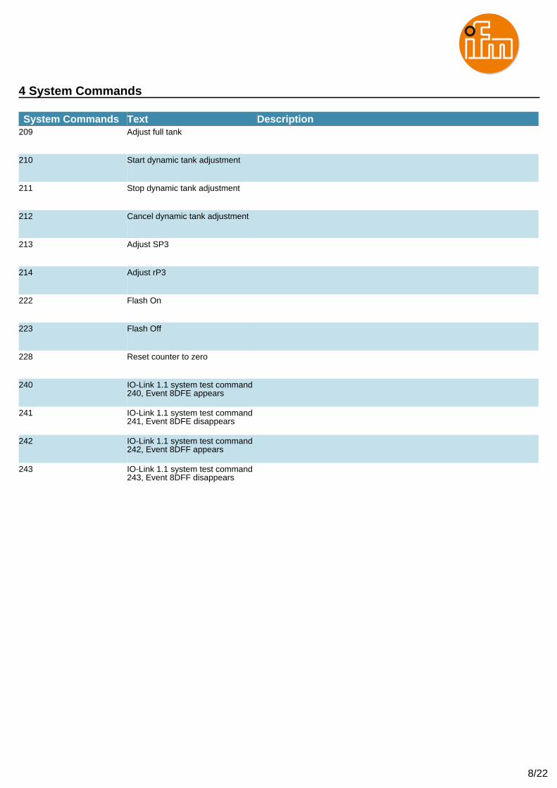
4 System Commands
System Commands Text Description209 Adjust full tank
210 Start dynamic tank adjustment
211 Stop dynamic tank adjustment
212 Cancel dynamic tank adjustment
213 Adjust SP3
214 Adjust rP3
222 Flash On
223 Flash Off
228 Reset counter to zero
240 IO-Link 1.1 system test command240, Event 8DFE appears
241 IO-Link 1.1 system test command241, Event 8DFE disappears
242 IO-Link 1.1 system test command242, Event 8DFF appears
243 IO-Link 1.1 system test command243, Event 8DFF disappears
9/22
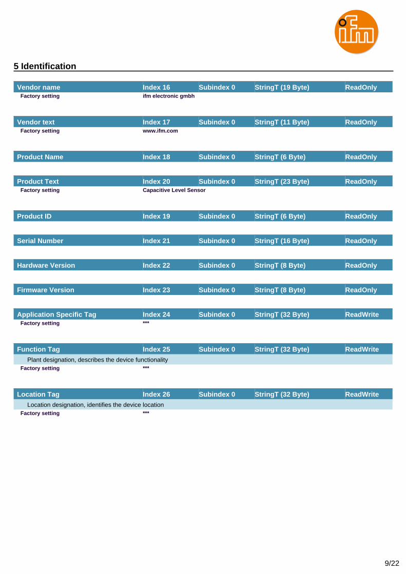
5 Identification
Vendor name Index 16 Subindex 0 StringT (19 Byte) ReadOnlyFactory setting ifm electronic gmbh
Vendor text Index 17 Subindex 0 StringT (11 Byte) ReadOnlyFactory setting www.ifm.com
Product Name Index 18 Subindex 0 StringT (6 Byte) ReadOnly
Product Text Index 20 Subindex 0 StringT (23 Byte) ReadOnlyFactory setting Capacitive Level Sensor
Product ID Index 19 Subindex 0 StringT (6 Byte) ReadOnly
Serial Number Index 21 Subindex 0 StringT (16 Byte) ReadOnly
Hardware Version Index 22 Subindex 0 StringT (8 Byte) ReadOnly
Firmware Version Index 23 Subindex 0 StringT (8 Byte) ReadOnly
Application Specific Tag Index 24 Subindex 0 StringT (32 Byte) ReadWriteFactory setting ***
Function Tag Index 25 Subindex 0 StringT (32 Byte) ReadWrite
Plant designation, describes the device functionalityFactory setting ***
Location Tag Index 26 Subindex 0 StringT (32 Byte) ReadWrite
Location designation, identifies the device locationFactory setting ***
10/22
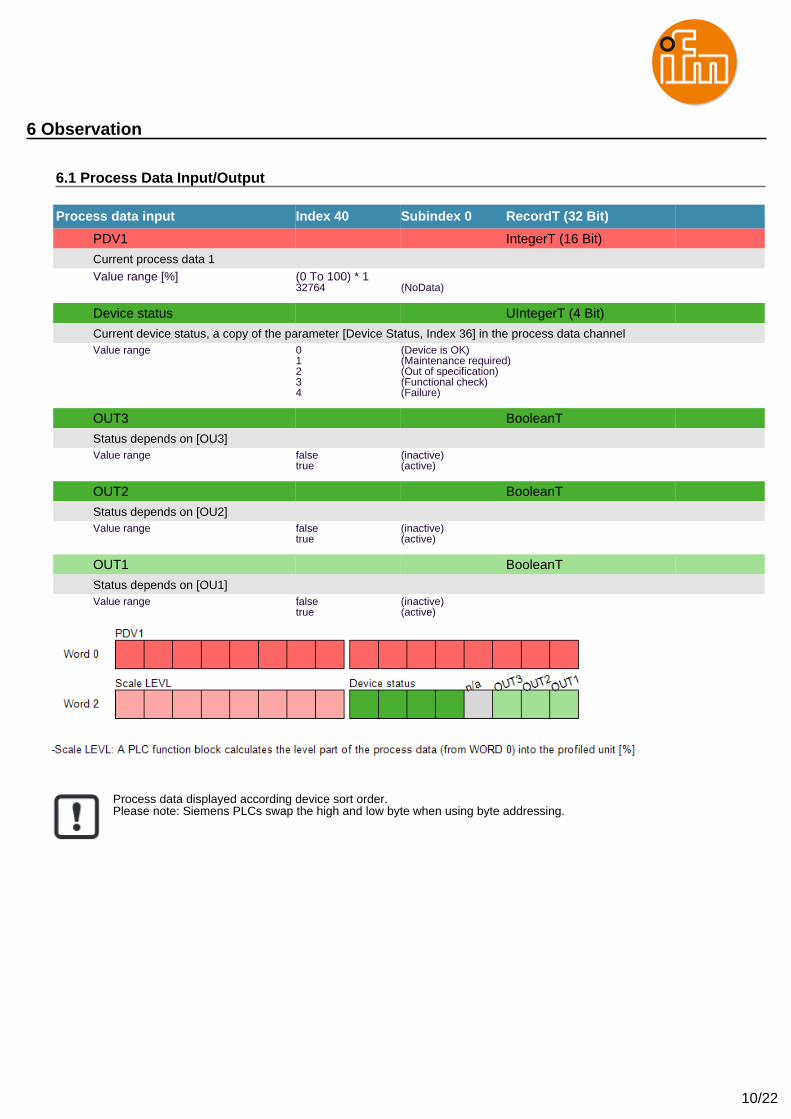
6 Observation
6.1 Process Data Input/Output
Process data input Index 40 Subindex 0 RecordT (32 Bit)
PDV1 IntegerT (16 Bit)
Current process data 1Value range [%] (0 To 100) * 1
32764 (NoData)
Device status UIntegerT (4 Bit)
Current device status, a copy of the parameter [Device Status, Index 36] in the process data channelValue range 0 (Device is OK)
1 (Maintenance required)2 (Out of specification)3 (Functional check)4 (Failure)
OUT3 BooleanT
Status depends on [OU3]Value range false (inactive)
true (active)
OUT2 BooleanT
Status depends on [OU2]Value range false (inactive)
true (active)
OUT1 BooleanT
Status depends on [OU1]Value range false (inactive)
true (active)
Process data displayed according device sort order.Please note: Siemens PLCs swap the high and low byte when using byte addressing.
11/22
7 Parameter
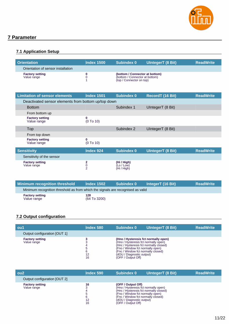
7.1 Application Setup
Orientation Index 1500 Subindex 0 UIntegerT (8 Bit) ReadWrite
Orientation of sensor installation
Factory setting 0 (bottom / Connector at bottom)Value range 0 (bottom / Connector at bottom)
1 (top / Connector on top)
Limitation of sensor elements Index 1501 Subindex 0 RecordT (16 Bit) ReadWrite
Deactivated sensor elements from bottom up/top down
Bottom Subindex 1 UIntegerT (8 Bit)
From bottom upFactory setting 0Value range (0 To 10)
Top Subindex 2 UIntegerT (8 Bit)
From top downFactory setting 0Value range (0 To 10)
Sensitivity Index 924 Subindex 0 UIntegerT (8 Bit) ReadWrite
Sensitivity of the sensor
Factory setting 2 (Hi / High)Value range 0 (Lo / Low)
2 (Hi / High)
Minimum recognition threshold Index 1502 Subindex 0 IntegerT (16 Bit) ReadWrite
Minimum recognition threshold as from which the signals are recognised as valid
Factory setting 128Value range (64 To 3200)
7.2 Output configuration
ou1 Index 580 Subindex 0 UIntegerT (8 Bit) ReadWrite
Output configuration [OUT 1]
Factory setting 3 (Hno / Hysteresis fct normally open)Value range 3 (Hno / Hysteresis fct normally open)
4 (Hnc / Hysteresis fct normally closed)5 (Fno / Window fct normally open)6 (Fnc / Window fct normally closed)12 (dOU / Diagnostic output)16 (OFF / Output Off)
ou2 Index 590 Subindex 0 UIntegerT (8 Bit) ReadWrite
Output configuration [OUT 2]
Factory setting 16 (OFF / Output Off)Value range 3 (Hno / Hysteresis fct normally open)
4 (Hnc / Hysteresis fct normally closed)5 (Fno / Window fct normally open)6 (Fnc / Window fct normally closed)12 (dOU / Diagnostic output)16 (OFF / Output Off)
12/22
7 Parameter
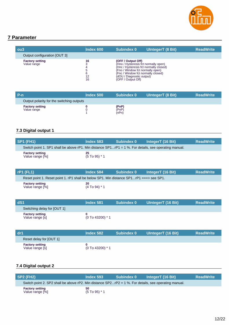
ou3 Index 600 Subindex 0 UIntegerT (8 Bit) ReadWrite
Output configuration [OUT 3]
Factory setting 16 (OFF / Output Off)Value range 3 (Hno / Hysteresis fct normally open)
4 (Hnc / Hysteresis fct normally closed)5 (Fno / Window fct normally open)6 (Fnc / Window fct normally closed)12 (dOU / Diagnostic output)16 (OFF / Output Off)
P-n Index 500 Subindex 0 UIntegerT (8 Bit) ReadWrite
Output polarity for the switching outputs
Factory setting 0 (PnP)Value range 0 (PnP)
1 (nPn)
7.3 Digital output 1
SP1 (FH1) Index 583 Subindex 0 IntegerT (16 Bit) ReadWrite
Switch point 1. SP1 shall be above rP1. Min distance SP1...rP1 = 1 %. For details, see operating manual.
Factory setting 25Value range [%] (5 To 95) * 1
rP1 (FL1) Index 584 Subindex 0 IntegerT (16 Bit) ReadWrite
Reset point 1. Reset point 1. rP1 shall be below SP1. Min distance SP1...rP1 ===> see SP1.
Factory setting 20Value range [%] (4 To 94) * 1
dS1 Index 581 Subindex 0 UIntegerT (16 Bit) ReadWrite
Switching delay for [OUT 1]
Factory setting 0Value range [s] (0 To 43200) * 1
dr1 Index 582 Subindex 0 UIntegerT (16 Bit) ReadWrite
Reset delay for [OUT 1]
Factory setting 0Value range [s] (0 To 43200) * 1
7.4 Digital output 2
SP2 (FH2) Index 593 Subindex 0 IntegerT (16 Bit) ReadWrite
Switch point 2. SP2 shall be above rP2. Min distance SP2...rP2 = 1 %. For details, see operating manual.
Factory setting 50Value range [%] (5 To 95) * 1
13/22
7 Parameter
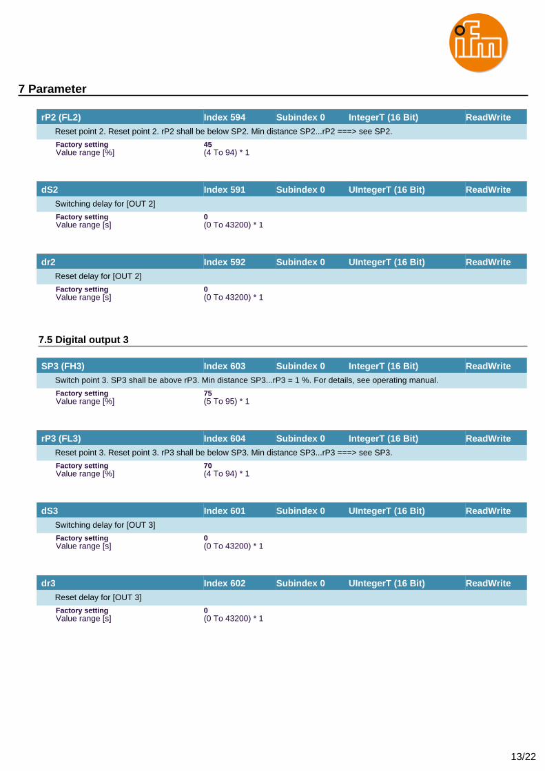
rP2 (FL2) Index 594 Subindex 0 IntegerT (16 Bit) ReadWrite
Reset point 2. Reset point 2. rP2 shall be below SP2. Min distance SP2...rP2 ===> see SP2.
Factory setting 45Value range [%] (4 To 94) * 1
dS2 Index 591 Subindex 0 UIntegerT (16 Bit) ReadWrite
Switching delay for [OUT 2]
Factory setting 0Value range [s] (0 To 43200) * 1
dr2 Index 592 Subindex 0 UIntegerT (16 Bit) ReadWrite
Reset delay for [OUT 2]
Factory setting 0Value range [s] (0 To 43200) * 1
7.5 Digital output 3
SP3 (FH3) Index 603 Subindex 0 IntegerT (16 Bit) ReadWrite
Switch point 3. SP3 shall be above rP3. Min distance SP3...rP3 = 1 %. For details, see operating manual.
Factory setting 75Value range [%] (5 To 95) * 1
rP3 (FL3) Index 604 Subindex 0 IntegerT (16 Bit) ReadWrite
Reset point 3. Reset point 3. rP3 shall be below SP3. Min distance SP3...rP3 ===> see SP3.
Factory setting 70Value range [%] (4 To 94) * 1
dS3 Index 601 Subindex 0 UIntegerT (16 Bit) ReadWrite
Switching delay for [OUT 3]
Factory setting 0Value range [s] (0 To 43200) * 1
dr3 Index 602 Subindex 0 UIntegerT (16 Bit) ReadWrite
Reset delay for [OUT 3]
Factory setting 0Value range [s] (0 To 43200) * 1
14/22
7 Parameter
7.6 Fault Configuration
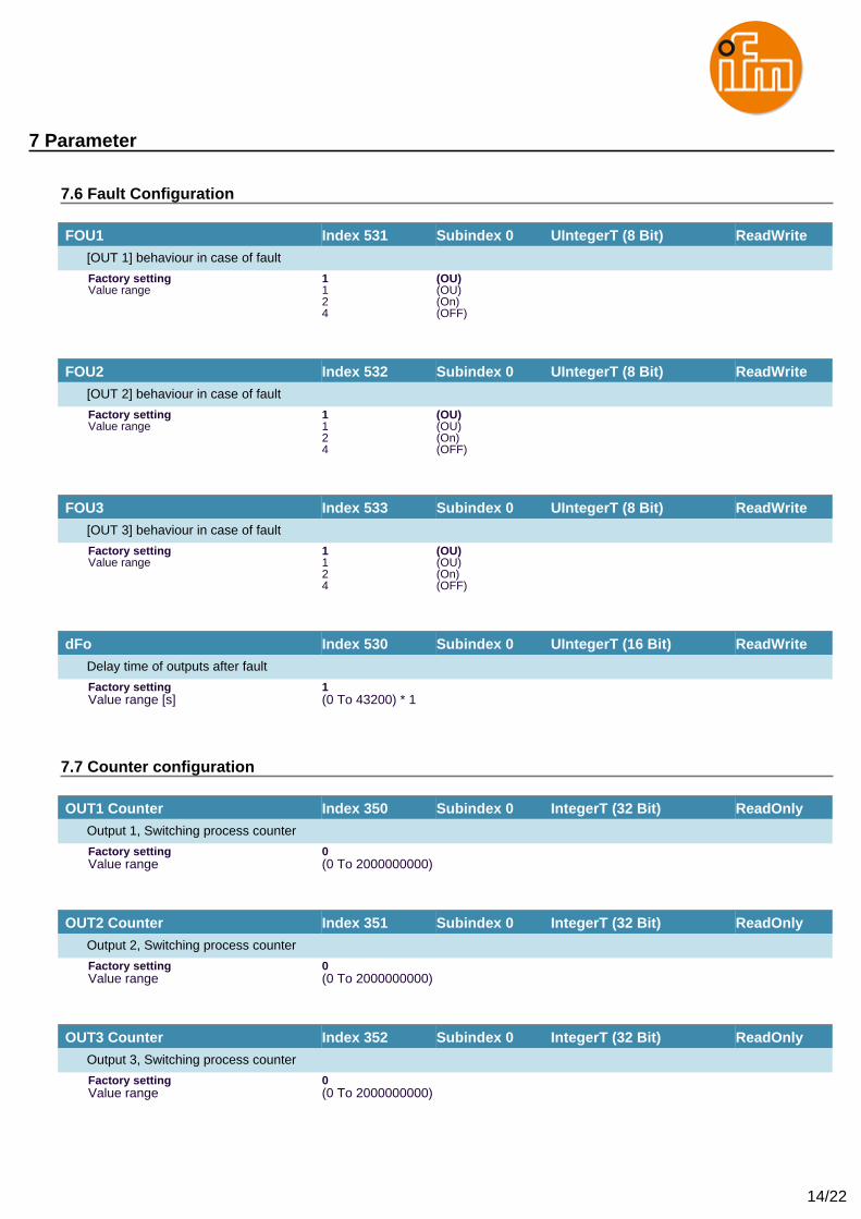
FOU1 Index 531 Subindex 0 UIntegerT (8 Bit) ReadWrite
[OUT 1] behaviour in case of fault
Factory setting 1 (OU)Value range 1 (OU)
2 (On)4 (OFF)
FOU2 Index 532 Subindex 0 UIntegerT (8 Bit) ReadWrite
[OUT 2] behaviour in case of fault
Factory setting 1 (OU)Value range 1 (OU)
2 (On)4 (OFF)
FOU3 Index 533 Subindex 0 UIntegerT (8 Bit) ReadWrite
[OUT 3] behaviour in case of fault
Factory setting 1 (OU)Value range 1 (OU)
2 (On)4 (OFF)
dFo Index 530 Subindex 0 UIntegerT (16 Bit) ReadWrite
Delay time of outputs after fault
Factory setting 1Value range [s] (0 To 43200) * 1
7.7 Counter configuration
OUT1 Counter Index 350 Subindex 0 IntegerT (32 Bit) ReadOnly
Output 1, Switching process counter
Factory setting 0Value range (0 To 2000000000)
OUT2 Counter Index 351 Subindex 0 IntegerT (32 Bit) ReadOnly
Output 2, Switching process counter
Factory setting 0Value range (0 To 2000000000)
OUT3 Counter Index 352 Subindex 0 IntegerT (32 Bit) ReadOnly
Output 3, Switching process counter
Factory setting 0Value range (0 To 2000000000)
15/22
7 Parameter
7.8 Damping
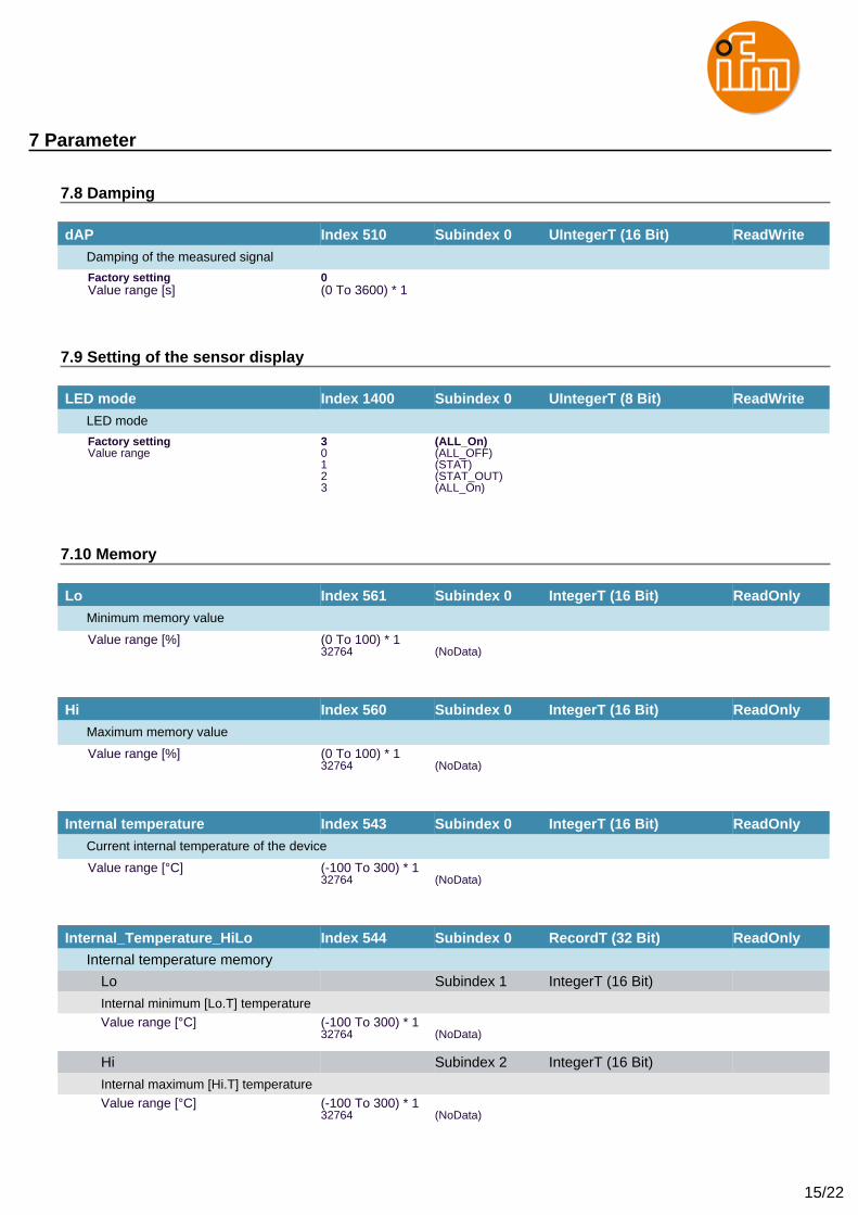
dAP Index 510 Subindex 0 UIntegerT (16 Bit) ReadWrite
Damping of the measured signal
Factory setting 0Value range [s] (0 To 3600) * 1
7.9 Setting of the sensor display
LED mode Index 1400 Subindex 0 UIntegerT (8 Bit) ReadWrite
LED mode
Factory setting 3 (ALL_On)Value range 0 (ALL_OFF)
1 (STAT)2 (STAT_OUT)3 (ALL_On)
7.10 Memory
Lo Index 561 Subindex 0 IntegerT (16 Bit) ReadOnly
Minimum memory value
Value range [%] (0 To 100) * 132764 (NoData)
Hi Index 560 Subindex 0 IntegerT (16 Bit) ReadOnly
Maximum memory value
Value range [%] (0 To 100) * 132764 (NoData)
Internal temperature Index 543 Subindex 0 IntegerT (16 Bit) ReadOnly
Current internal temperature of the device
Value range [°C] (-100 To 300) * 132764 (NoData)
Internal_Temperature_HiLo Index 544 Subindex 0 RecordT (32 Bit) ReadOnly
Internal temperature memory
Lo Subindex 1 IntegerT (16 Bit)
Internal minimum [Lo.T] temperatureValue range [°C] (-100 To 300) * 1
32764 (NoData)
Hi Subindex 2 IntegerT (16 Bit)
Internal maximum [Hi.T] temperatureValue range [°C] (-100 To 300) * 1
32764 (NoData)
16/22
7 Parameter
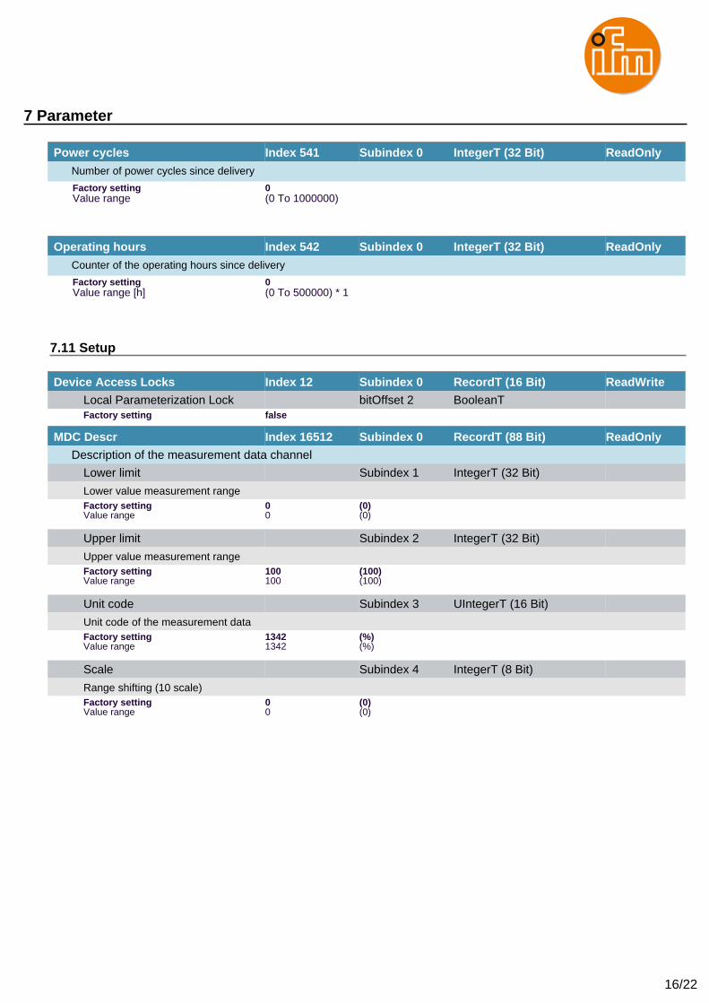
Power cycles Index 541 Subindex 0 IntegerT (32 Bit) ReadOnly
Number of power cycles since delivery
Factory setting 0Value range (0 To 1000000)
Operating hours Index 542 Subindex 0 IntegerT (32 Bit) ReadOnly
Counter of the operating hours since delivery
Factory setting 0Value range [h] (0 To 500000) * 1
7.11 Setup
Device Access Locks Index 12 Subindex 0 RecordT (16 Bit) ReadWrite
Local Parameterization Lock bitOffset 2 BooleanTFactory setting false
MDC Descr Index 16512 Subindex 0 RecordT (88 Bit) ReadOnly
Description of the measurement data channel
Lower limit Subindex 1 IntegerT (32 Bit)
Lower value measurement rangeFactory setting 0 (0)Value range 0 (0)
Upper limit Subindex 2 IntegerT (32 Bit)
Upper value measurement rangeFactory setting 100 (100)Value range 100 (100)
Unit code Subindex 3 UIntegerT (16 Bit)
Unit code of the measurement dataFactory setting 1342 (%)Value range 1342 (%)
Scale Subindex 4 IntegerT (8 Bit)
Range shifting (10 scale)Factory setting 0 (0)Value range 0 (0)
17/22
8 Diagnosis
8.1 Diagnosis
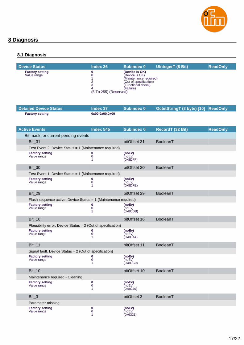
Device Status Index 36 Subindex 0 UIntegerT (8 Bit) ReadOnlyFactory setting 0 (Device is OK)Value range 0 (Device is OK)
1 (Maintenance required)2 (Out of specification)3 (Functional check)4 (Failure)(5 To 255) (Reserved)
Detailed Device Status Index 37 Subindex 0 OctetStringT (3 byte) [10] ReadOnlyFactory setting 0x00,0x00,0x00
Active Events Index 545 Subindex 0 RecordT (32 Bit) ReadOnly
Bit mask for current pending events
Bit_31 bitOffset 31 BooleanT
Test Event 2. Device Status = 1 (Maintenance required)Factory setting 0 (noEv)Value range 0 (noEv)
1 (0x8DFF)
Bit_30 bitOffset 30 BooleanT
Test Event 1. Device Status = 1 (Maintenance required)Factory setting 0 (noEv)Value range 0 (noEv)
1 (0x8DFE)
Bit_29 bitOffset 29 BooleanT
Flash sequence active. Device Status = 1 (Maintenance required)Factory setting 0 (noEv)Value range 0 (noEv)
1 (0x8CDB)
Bit_16 bitOffset 16 BooleanT
Plausibility error. Device Status = 2 (Out of specification)Factory setting 0 (noEv)Value range 0 (noEv)
1 (0x8CA4)
Bit_11 bitOffset 11 BooleanT
Signal fault. Device Status = 2 (Out of specification)Factory setting 0 (noEv)Value range 0 (noEv)
1 (0x8CC0)
Bit_10 bitOffset 10 BooleanT
Maintenance required - CleaningFactory setting 0 (noEv)Value range 0 (noEv)
1 (0x8C40)
Bit_3 bitOffset 3 BooleanT
Parameter missingFactory setting 0 (noEv)Value range 0 (noEv)
1 (0x6321)
18/22
8 Diagnosis
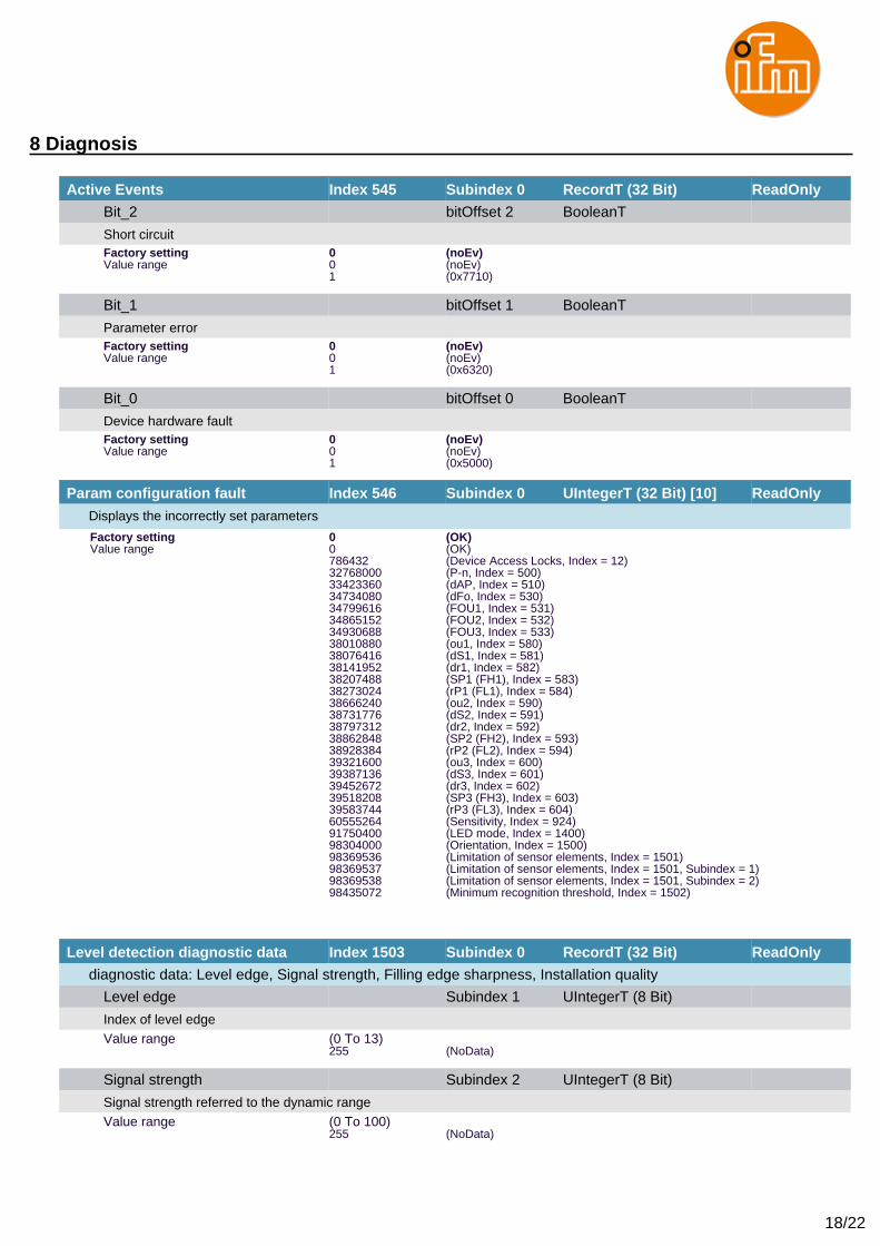
Active Events Index 545 Subindex 0 RecordT (32 Bit) ReadOnly
Bit_2 bitOffset 2 BooleanT
Short circuitFactory setting 0 (noEv)Value range 0 (noEv)
1 (0x7710)
Bit_1 bitOffset 1 BooleanT
Parameter errorFactory setting 0 (noEv)Value range 0 (noEv)
1 (0x6320)
Bit_0 bitOffset 0 BooleanT
Device hardware faultFactory setting 0 (noEv)Value range 0 (noEv)
1 (0x5000)
Param configuration fault Index 546 Subindex 0 UIntegerT (32 Bit) [10] ReadOnly
Displays the incorrectly set parameters
Factory setting 0 (OK)Value range 0 (OK)
786432 (Device Access Locks, Index = 12)32768000 (P-n, Index = 500)33423360 (dAP, Index = 510)34734080 (dFo, Index = 530)34799616 (FOU1, Index = 531)34865152 (FOU2, Index = 532)34930688 (FOU3, Index = 533)38010880 (ou1, Index = 580)38076416 (dS1, Index = 581)38141952 (dr1, Index = 582)38207488 (SP1 (FH1), Index = 583)38273024 (rP1 (FL1), Index = 584)38666240 (ou2, Index = 590)38731776 (dS2, Index = 591)38797312 (dr2, Index = 592)38862848 (SP2 (FH2), Index = 593)38928384 (rP2 (FL2), Index = 594)39321600 (ou3, Index = 600)39387136 (dS3, Index = 601)39452672 (dr3, Index = 602)39518208 (SP3 (FH3), Index = 603)39583744 (rP3 (FL3), Index = 604)60555264 (Sensitivity, Index = 924)91750400 (LED mode, Index = 1400)98304000 (Orientation, Index = 1500)98369536 (Limitation of sensor elements, Index = 1501)98369537 (Limitation of sensor elements, Index = 1501, Subindex = 1)98369538 (Limitation of sensor elements, Index = 1501, Subindex = 2)98435072 (Minimum recognition threshold, Index = 1502)
Level detection diagnostic data Index 1503 Subindex 0 RecordT (32 Bit) ReadOnly
diagnostic data: Level edge, Signal strength, Filling edge sharpness, Installation quality
Level edge Subindex 1 UIntegerT (8 Bit)
Index of level edgeValue range (0 To 13)
255 (NoData)
Signal strength Subindex 2 UIntegerT (8 Bit)
Signal strength referred to the dynamic rangeValue range (0 To 100)
255 (NoData)
19/22
8 Diagnosis
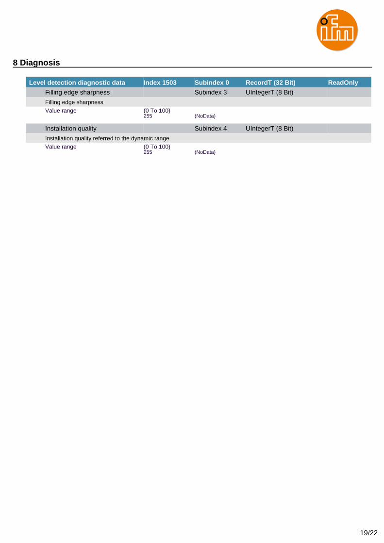
Level detection diagnostic data Index 1503 Subindex 0 RecordT (32 Bit) ReadOnly
Filling edge sharpness Subindex 3 UIntegerT (8 Bit)
Filling edge sharpnessValue range (0 To 100)
255 (NoData)
Installation quality Subindex 4 UIntegerT (8 Bit)
Installation quality referred to the dynamic rangeValue range (0 To 100)
255 (NoData)
20/22
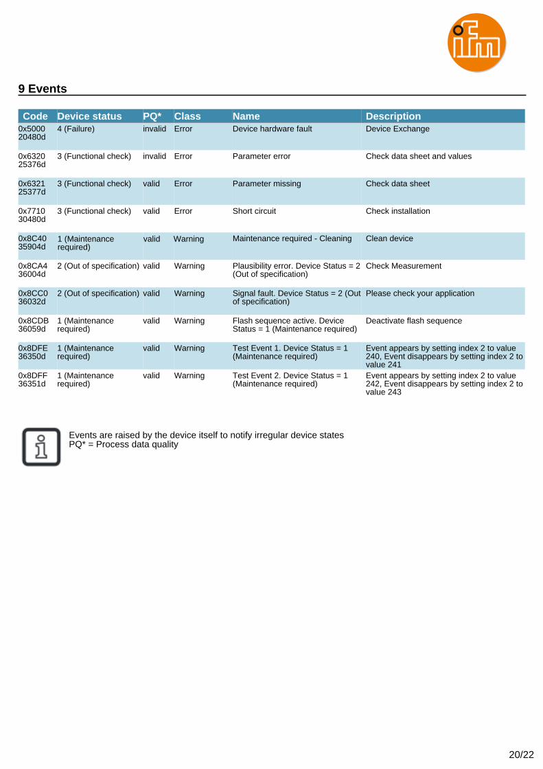
9 Events
Code Device status PQ* Class Name Description0x500020480d
4 (Failure) invalid Error Device hardware fault Device Exchange
0x632025376d
3 (Functional check) invalid Error Parameter error Check data sheet and values
0x632125377d
3 (Functional check) valid Error Parameter missing Check data sheet
0x771030480d
3 (Functional check) valid Error Short circuit Check installation
0x8C4035904d
unchanged valid Notification Maintenance required - Cleaning Clean device
0x8CA436004d
2 (Out of specification) valid Warning Plausibility error. Device Status = 2(Out of specification)
Check Measurement
0x8CC036032d
2 (Out of specification) valid Warning Signal fault. Device Status = 2 (Outof specification)
Please check your application
0x8CDB36059d
1 (Maintenancerequired)
valid Warning Flash sequence active. DeviceStatus = 1 (Maintenance required)
Deactivate flash sequence
0x8DFE36350d
1 (Maintenancerequired)
valid Warning Test Event 1. Device Status = 1(Maintenance required)
Event appears by setting index 2 to value240, Event disappears by setting index 2 tovalue 241
0x8DFF36351d
1 (Maintenancerequired)
valid Warning Test Event 2. Device Status = 1(Maintenance required)
Event appears by setting index 2 to value242, Event disappears by setting index 2 tovalue 243
Events are raised by the device itself to notify irregular device statesPQ* = Process data quality
nnnnnnnnnnnnnnnnnnn nnnnnnnn1 (Maintenancerequired)
valid Warning
21/22
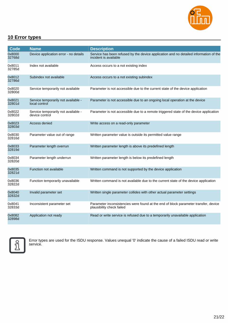
10 Error types
Code Name Description0x800032768d
Device application error - no details Service has been refused by the device application and no detailed information of theincident is available
0x801132785d
Index not available Access occurs to a not existing index
0x801232786d
Subindex not available Access occurs to a not existing subindex
0x802032800d
Service temporarily not available Parameter is not accessible due to the current state of the device application
0x802132801d
Service temporarily not available -local control
Parameter is not accessible due to an ongoing local operation at the device
0x802232802d
Service temporarily not available -device control
Parameter is not accessible due to a remote triggered state of the device application
0x802332803d
Access denied Write access on a read-only parameter
0x803032816d
Parameter value out of range Written parameter value is outside its permitted value range
0x803332819d
Parameter length overrun Written parameter length is above its predefined length
0x803432820d
Parameter length underrun Written parameter length is below its predefined length
0x803532821d
Function not available Written command is not supported by the device application
0x803632822d
Function temporarily unavailable Written command is not available due to the current state of the device application
0x804032832d
Invalid parameter set Written single parameter collides with other actual parameter settings
0x804132833d
Inconsistent parameter set Parameter inconsistencies were found at the end of block parameter transfer, deviceplausibility check failed
0x808232898d
Application not ready Read or write service is refused due to a temporarily unavailable application
Error types are used for the ISDU response. Values unequal '0' indicate the cause of a failed ISDU read or writeservice.
22/22
Additional device-specific information On delivery, the unit is not operational! First of all the sensor has to be adjusted to the application / the tank (see
operating instructions). Only carry out the tank adjustment when the unit is installed!
The sensor calculates the level based on the measured capacitances of its individual measuring segments. To ensure
correct calculation the measured capacitances have to be comparable. This means that in some applications
additional grounding may become necessary (see operating instructions, chapter Troubleshooting).
Note! The tank adjustment is not part of the data storage!
After unit replacement, adjustment has to be made again manually via IO-Link. Only when the tank adjustment has
been carried out successfully does the unit revert to the cyclical process data transmission.
Note!
After a factory reset, the factory settings are restored.
The unit is not operational!
Adjustment options (standard commands)
Adjust empty tank: The process value of the unit is adjusted to an empty tank.
"Empty" means the level is below the detection range.
Adjust full tank: The process value of the unit is adjusted to a full tank.
"Full" means the level is above the detection range.
Dynamic tank adjustment: The process value of the unit is adjusted to the level in the measurement range
during the time window (start to stop). During the entire time window, the level has
to be in the measuring range! The dynamic adjustment does not have a timeout and
therefore always has to be stopped or aborted via IO-Link.
For non-changing products, the highest operational reliability is obtained by carrying out empty and full adjustments.
These two adjustments are also recommended for adhering products if they remain unchanged.
Deposits can only be detected when empty and full adjustments have been made!
For changing products (with extremely different dielectric constants) only the adjustment to the empty tank should
be made.
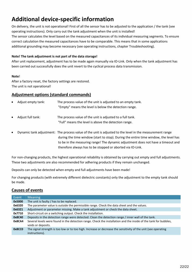
Causes of events
Event Meaning 0x5000 The unit is faulty / has to be replaced. 0x6320 The parameter value is outside the permissible range. Check the data sheet and the values. 0x6321 Adjustment or parameter missing. Make a tank adjustment or check the data sheet. 0x7710 Short-circuit on a switching output. Check the installation. 0x8C40 Deposits in the detection range were detected. Clean the detection range / inner wall of the tank. 0x8CA4 Several levels were found in the detection range. Check the installation and the inside of the tank for bubbles,
voids or deposits. 0x8CC0 The signal strength is too low or to too high. Increase or decrease the sensitivity of the unit (see operating
instructions).