INSTALLATION MANUALVENTUM SERIES

Table of Contents
1. General Information 3
2. Installation 4
2.1 Unwrapping the Product 4
2.2 Assembly 4
2.3 Weights 5
2.4 Installation 5
2.4.1 Ceiling Mount 5
2.5 Installation of Accessories 7
2.5.1 Coupled Accessories 7
2.5.2 Decoupled Accessories 9
2.6 External Sensors 10
2.6.1 Supply Air Temperature Sensor 10
2.6.2 Pressure Sensor 10
2.6.3 CO2/VOC Sensor 11
2.6.4 Combination Temperature 12
/Humidity Sensor
3. Access Requirements 13
4. Lifting Requirements 13
5. Electrical Hook-Ups 14
5.1 Electrical Information 15
5.2 1PH Electrical Hook Up (2 Fans) 16
5.3 3PH Electrical Hook Up (2 Fans) 17
5.6 1PH Lite Electrical Hook Up (2 Fans) 18
5.7 3PH Lite Electrical Hook Up (2 Fans) 19
6.0 Wiring Diagrams 20
6.1 Ventum 240V, Single Phase, S1 21
6.2 Ventum 240V, Single Phase S2 22
6.3 Ventum, Three Phase, S1 23
6.4 Ventum, Three Phase, S2 24
6.5 Field Wiring, DX Coil, EKE 25
6.6 Field Wiring, DX Coil, Electric Reheat, EKE 26
6.7 Field Wiring, Electric Preheat, DX Coil 27 Electric Reheat, EKE
6.8 Field Wiring, Electric Preheat, DX Coil, EKE 28
6.9 Field Wiring, Damper Wiring 29
6.10 Field Wiring, Electric Reheat Wiring 30
6.11 Field Wiring, Electric Preheat, 31 Electric Reheat Wiring
6.12 Field Wiring, Electric Preheat Wiring 32
6.13 Field Wiring, Cooling Water Coil 33
6.14 Field Wiring, Humidity Control 34
6.15 Field Wiring, Combi Coil 35
6.16 Field Wiring, Hydronic Preheat 36
6.17 Field Wiring, Occupancy Mode 37
6.18 Field Wiring, Hydronic Reheat 38
6.19 Field Wiring, Fire Alarm 39
6.20 Field Wiring, DX Coil, Hydronic Reheat 40 EKE, Bypass 6.21 Field Wiring, CO2 Control, 41 External Bypass
Installation Manual Ventum Series
3
This manual includes important instructions for safe connection of the Heat Recovery Ventilator (HRV) or Energy Recovery Ventilator (ERV). Before connecting the unit, please read carefully and follow all of the instructions below! The manufacturer reserves the right to make changes, including changes in the technical documentation, without previous notification. Please keep this manual for future reference. Consider this manual a permanent part of the product.
This manual will show the manufacturers' recommended installation method. Please note that local codes and regulations may override these recommendations. The installation must follow local codes and standards.
The National Electric Code (NEC), the National Fire Protection Agency (NFPA), and the Canadian Electrical Code (CEC) must be followed. Installation of this product must be performed by a qualified and accredited professional in conformance with local and national codes, standards and licensing requirements.
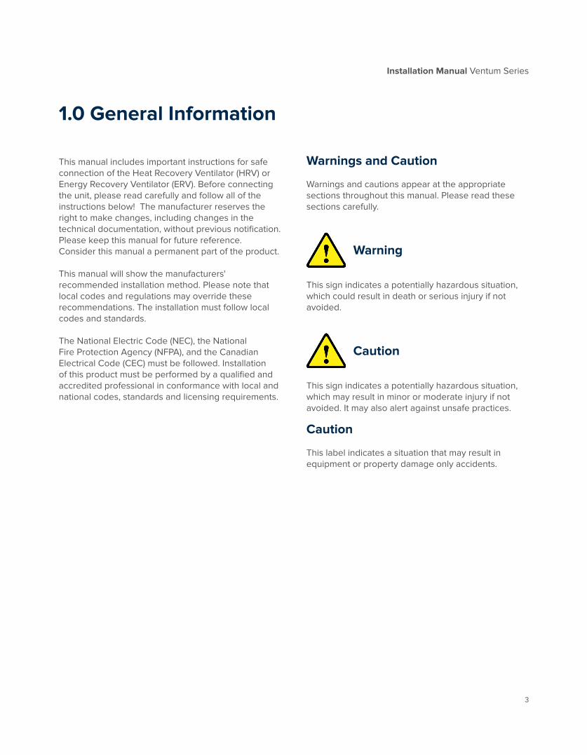
Warnings and Caution
Warnings and cautions appear at the appropriate sections throughout this manual. Please read these sections carefully.
Warning
This sign indicates a potentially hazardous situation, which could result in death or serious injury if not avoided.
Caution
This sign indicates a potentially hazardous situation, which may result in minor or moderate injury if not avoided. It may also alert against unsafe practices.
Caution
This label indicates a situation that may result in equipment or property damage only accidents.
1.0 General Information

Installation Manual Ventum Series
4
2.1 Unwrapping the Product
When removing the shrink wrap, be cautious with knives and sharp tools to prevent scratching the paint.
The HMI, pressure sensor, external duct pressure sensor and all other optional field components will be found in the electrical box or fan compartment. They are secured there for transport and to easily find them on the job site.
2.2 Assembly
Remove the middle panel for wiring access. Fans and filters are accessible via the bottom doors. Fans should be pre-wired and no assembly is required.
Use the following steps to disassemble the fan section from the core section.
1. Remove the cover from the fan.
2. Undo the screw terminals that are holding the power wires and the communication wires. *See back of manual for electrical drawings.
3. Loosen the cable glands and pull the wires out of the motor.
4. Pull the pressure tube from the nozzle port on the fan bell mouth.
5. Push the pressure tube and all cables back into the core section, through the rubber grommets that are on the fan wall.
6. Repeat steps 1 ― 5 for the other fan.
2.0 Installation
1 2 43 5
Unit Wrapped
for Shipping
4x Corner

Installation Manual Ventum Series
5
2.3 Weights
Model Fan (A) lbs. Core (B) lbs. Total Weight lbs.
H05 27 13 450
H10 28.7 13 620
H15 37.5 22 720
H20 37.5 22 820
H25 48.5 64 1130
H30 48.5 64 1300
A
B
2.4 Installation
2.4.1 Ceiling Mount
Ventum is available exclusively for ceiling mount/horizontal applications with inner and outer brackets only. The hanging brackets are supplied loose with the necessary hardware to install them. They are not shipped assembled due to the variability of installation access on job sites. The front panel of the unit must be removed to slide the core into the unit.
Each hanging bracket is composed of two pieces: an inner component and an outer component. The units are designed to have four sets of brackets to support the unit.
Note Depending on the ducted opening location selected during the design phase, the location of the brackets will vary. Please consult your submittal drawings for specific locations.
Inner Bracket
OuterBracket
Warning
The unit must be installed with both the inner and outer bracket. Each unit must also have all four brackets installed to meet these guidelines.
Ceiling Mounted Unit

Installation Manual Ventum Series
6
Assembly of Hanging Brackets
1. Locate the position of the brackets on the outside of the unit.
2. Mark the 8 hole locations and drill to allow for the ¼" bolt. 32 - ¼" bolts, 32 - ¼" lock nut, 32 - ¼" washers and 64 - ¼" washers have been provided with the unit.
3. Assemble the hanging bracket by aligning the 8 holes of the outer bracket through the unit and with the inner bracket. Note: the inner component should be oriented so that its flange is pointing to the ceiling, and the outer bracket has the single hole pointing to the ceiling.
4. Install the 8 bolts. Caution - Do not over tighten and crush the panel.
5. Install 4 tek-screws in the flange portion of the inner bracket and secure it to the top casing of the unit.
6. Install 4 tek-screws in the lower flange of the outer bracket to secure it to the bottom frame of the unit.
7. Repeat steps 1 through 6 for the remainder of the brackets.
8. The hole in the outer brackets are designed for a ½" threaded rod to hang the units by.
Bracket Alignment

Installation Manual Ventum Series
7
2.5 Installation of Accessories
2.5.1 Coupled Accessories
Coupled Accessory with Ceiling Mounted Unit
Mounted Coupled Accessory

Installation Manual Ventum Series
8
Corner brackets come pre-installed with each Ventum unit. Accessories should be independently supported with Unistrut on the end farthest from the unit. Base mounted accessories that are connect to a duct connection in the lower position of the unit will come with matching base rails.
Accessories that are to be connected to a duct connection in the upper position will need to be supported externally.
1 2
Installation Manual Ventum Series
9
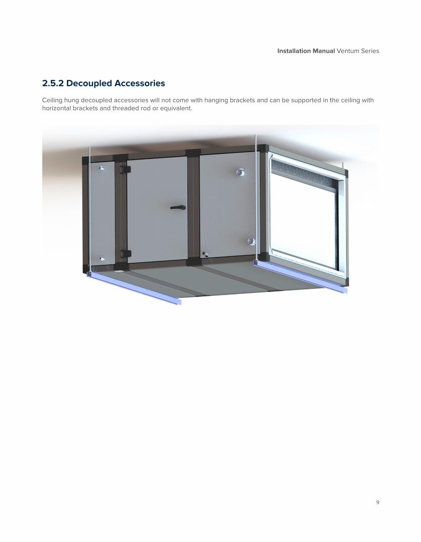
2.5.2 Decoupled Accessories
Ceiling hung decoupled accessories will not come with hanging brackets and can be supported in the ceiling with horizontal brackets and threaded rod or equivalent.
Installation Manual Ventum Series
10
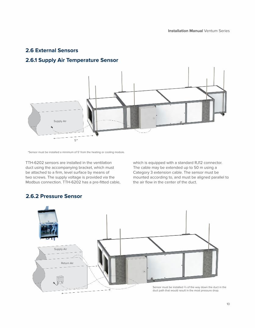
2.6 External Sensors
2.6.1 Supply Air Temperature Sensor
TTH-6202 sensors are installed in the ventilation duct using the accompanying bracket, which must be attached to a firm, level surface by means of two screws. The supply voltage is provided via the Modbus connection. TTH-6202 has a pre-fitted cable,
which is equipped with a standard RJ12 connector. The cable may be extended up to 50 m using a Category 3 extension cable. The sensor must be mounted according to, and must be aligned parallel to the air flow in the center of the duct.
*Sensor must be installed a minimum of 5' from the heating or cooling module.
2.6.2 Pressure Sensor
Sensor must be installed ⅔ of the way down the duct in the duct path that would result in the most pressure drop.
Supply Air
Return Air
5'*
Supply Air

Installation Manual Ventum Series
11
2.6.3 CO2/VOC Sensor
VTH-6202 sensors are installed in the ventilation duct using the accompanying bracket, which must be attached to a firm, level surface by means of two screws. The 18-30 V DC supply voltage (24 V DC nominal voltage) is provided via the Modbus connection. VTH-6202 has a pre-fitted 7000 mm cable, which is equipped with a standard RJ12 connector. The cable may be extended to as much as 50 m without any negative effects on measuring accuracy. The surrounding EMC environment must, however, be taken into account and must be capable of being defined as
low. To extend the cable, use a crossover Category 3 extension cable, RJ12-RJ12, 6P6C. The sensor should be installed in such a way that the air flow in the duct can pass unhindered through the measuring hole at the end of the sensor, which should be aligned parallel to the air flow. Although the VTH-6202 is not affected by the position in which it is installed, it should not be installed in an upright position with the cable downwards as this may cause moisture to accumulate in the sensor.
The enclosure is opened without the use of tools by pressing the snap lock at the side of the tube connectors. PTH-6202 is attached onto a level surface by 2 screws, which are screwed into a solid surface. PTH-6202 can be fitted in all directions without accuracy being affected. PTH-6202 also functions with only one tube fitted to the connectors (+ or -). However, two tubes should always be fitted to ensure a suitable enclosure rating, if the connectors do not face downwards. Pressure is supplied to the measurement unit by tubes, the highest pressure being connected to the ‘+ connector’ and the lowest
pressure to ‘- connector’. The pressure tubes must be as short as possible and must be secured in position to prevent vibration. To obtain the best possible results, pressure must be measured where there is least risk of turbulence, i.e. in the center of the ventilation duct and at a distance of at least twice the width of the duct from bends and six times the width from branches. If there is a risk of condensation forming in connection tubes, PTH-6202 is to be located in such a way that condensate fluids cannot flow back into the pressure transmitter.
Supply Air
Return Air
In duct view

Installation Manual Ventum Series
12
2.6.4 Combination Temperature/ Humidity Sensor
HTH-6202 sensors are installed in the ventilation duct using the accompanying bracket, which must be attached to a firm, level surface by means of two screws. The 18-30 V DC supply voltage (24 V DC nominal voltage) is provided via the Modbus connection. HTH-6202 has a pre-fitted 7000 mm cable, which is equipped with a standard RJ12
connector. The cable may be extended to as much as 50 m without any negative effects on measuring accuracy. The surrounding EMC environment must, however, be taken into account and must be capable of being defined as low. To extend the cable, use a crossover Category 3 extension cable, RJ12-RJ12, 6P6C. The sensor should be installed in such a way that the air flow in the duct can pass unhindered through the measuring hole at the end of the sensor, which should be aligned parallel to the air flow. Although HTH-6202 is not affected by the position in which it is installed, it is advisable not to install the sensor in an upright position with the cable downwards as this may cause moisture to accumulate in the sensor. It is important that HTH-6202 is installed in such a way that the measuring hole is positioned at the center of the duct.
5'*
*Sensor must be installed a minimum of 5' from the heating or cooling module.
In duct view
Supply Air

Installation Manual Ventum Series
13
3.0 Access Requirements
Top of Unit
The National Electrical Code (NEC) requires 36 inches of clearance from an electrical connection. For Ventum, with a front-mounted electrical box, the 3’ must be measured from the front of the box. The unit should be mounted such that the bottom doors remain accessible.
4.0 Lifting RequirementsUnits can be lifted by mounting angles. Lifting directly from the frame is not recommended.
Door with removed hinge pinUnit with doors open

Installation Manual Ventum Series
14
Installation Manual Ventum Series
5.0 Electrical Hook Ups
Warning
Hazardous voltage, disconnect all electrical power, including remote disconnects and discharge all motor start/run capacitors before servicing. Follow proper lockout/tagout procedures to ensure the power cannot be accidentally re-engaged.
3 phase, 4 wire, 208V, 460V -10% - +15%, 60Hz
Recommended fuse diagram
1 phase, 3 wire, 240V -10% - +15%, 60Hz
Recommended fuse diagram
Unit Size 208V 460V
C24-ERV 25A 15A
C30-ERV 25A 15A
C24-FC 15A 15A
C30-FC 20A 15A
Unit Size 208V
A16-ERV 15A
B20-ERV 15A
A16-FC 15A
B20-FC 15A
Installation Manual Ventum Series
15
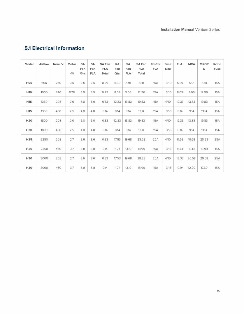
5.1 Electrical Information
Model
Airflow
Nom. V.
Motor
kW
SA
Fan
Qty.
SA
Fan
FLA
SA Fan
FLA
Total
RA
Fan
Qty.
SA
Fan
FLA
SA Fan
FLA
Total
Tnsfmr
FLA
Fuse
Size
FLA
MCA
MROP
D
Rcmd
Fuse
H05 600 240 0.5 2.5 2.5 0.29 5.39 5.91 8.41 15A 3/10 5.29 5.91 8.41 15A
H10 1000 240 0.78 3.9 3.9 0.29 8.09 9.06 12.96 15A 3/10 8.09 9.06 12.96 15A
H15 1350 208 2.0 6.0 6.0 0.33 12.33 13.83 19.83 15A 4/10 12.33 13.83 19.83 15A
H15 1350 460 2.5 4.0 4.0 0.14 8.14 9.14 13.14 15A 3/16 8.14 9.14 13.14 15A
H20 1800 208 2.0 6.0 6.0 0.33 12.33 13.83 19.83 15A 4/10 12.33 13.83 19.83 15A
H20 1800 460 2.5 4.0 4.0 0.14 8.14 9.14 13.14 15A 3/16 8.14 9.14 13.14 15A
H25 2250 208 2.7 8.6 8.6 0.33 17.53 19.68 28.28 25A 4/10 17.53 19.68 28.28 25A
H25 2250 460 3.7 5.8 5.8 0.14 11.74 13.19 18.99 15A 3/16 11.74 13.19 18.99 15A
H30 3000 208 2.7 8.6 8.6 0.33 17.53 19.68 28.28 25A 4/10 18.33 20.58 29.58 25A
H30 3000 460 3.7 5.8 5.8 0.14 11.74 13.19 18.99 15A 3/16 10.94 12.29 17.69 15A

Installation Manual Ventum Series
16
Pieces:2021-02-11
Scale:
Drawn by:Approved by:Date:
Material:Weight:
Name:
Drawing number:
PM
FANMOTOR
FANMOTOR
DATA
CAB
LEDA
TA C
ABLE
0-10V
0-10V
L1 L2 L3GND
t t
t t
tENCLOSURE
4/10A for 208V3/16A for 460V
208V or 460V
24V
1/L1
3/L2
5/L3
2/T1
4/T2
6/T3
I> I> I>
1/L1
3/L2
5/L3
2/T1
4/T2
6/T3
I> I> I>
O28-05-0003-23
NOVA WIRING LAYOUT 3-PHASE
Pieces:2021-02-11
Scale:
Drawn by:Approved by:Date:
Material:Weight:
Name:
Drawing number:
PM
L1 240V
O28-05-0003-24
NOVA WIRING LAYOUT SINGLE PHASE
FANMOTOR
FANMOTOR
DATA
CAB
LEDA
TA C
ABLE
0-10V
0-10V
GND
t t
t t
tENCLOSURE
3/10A
24V
N
FAN I/0 R/ABOTTOM
FAN I/0 S/ATOP
6
5
3
4
1
7
8
POSITION PCsTYPE1234
6 15
COLOUR PART No.
11134
22/6 COMMUNICATION MODBUS
78 1
122/6 COMMUNICATION MODBUS
18/4 (3 PHASE/GRD) POWER18/4 (3 PHASE/GRD) POWER
18/2 (0-10V, GRD) COMMNS.18/2 (0-10V, GRD) COMMNS.
Pieces:2020-04-02
Scale:
Drawn by:Approved by:Date:
Material:Weight:
Name:
Drawing number:
O28-05-0003-01A
PMELE. BOX WIRING LAYOUT - 208V3-PHASE
1
FAN R/A(BOTTOM)
FAN S/A(TOP)
BLACKBLACKGRAYGRAYBLACKBLACKBLACKBLACK
LC LC
24V
TRANSFORMER
T1T2T3 SWITCH BODY
T1 T2
MMP1 MMP2
GREE
N
GREE
N
WHI
TE
BLAC
K
RED
WHI
TE
BLAC
K
REDFOR T1, T2 CONNECTION
SEE 208V TRANSFORMERWIRING DIAGRAM T1
BLA
CK
T2 B
LACK
C
T1 T2 T3
222
1
1
SINGLE WIRE 10Ga, L=9"SINGLE WIRE 10Ga, L=14"
9
9
9 2FAN JUMPER 18GaBLACK
WIP0010WIP0010
WIP0017WIP0018WIP0022WIP0021WIP0019WIP0020WIP0023
FOR WIRES CONNECTIONSEE 208V TRANSFORMER
WIRING DIAGRAM
Pre-heattemperature sensoris placed in top orbottom core bracket.
17-WHITE16-BLACK2-BLUE1-RED
3-PH
ASE
208V
PO
WER
SO
URCE
24V
TRANSFORMER
T1
18/3 (HOT, NEUTRAL, GROUND)
WHI
TE 1
WHI
TE 2
GREE
N 1
GREE
N 2
BLAC
K 1
BLAC
K 2
M9F1
M9F2
FOR T1CONNECTION
SEE 240VTRANSFORMER
WIRINGDIAGRAM
POWER BOXPOSITION PCsTYPE
1
34 1
COLOUR A16
11211
22/6 COMMUNICATION MODBUS56789 1
111
22/6 COMMUNICATION MODBUS18/2 0-10V, GRD COMMUNICATION18/2 0-10V, GRD COMMUNICATION
2
4
5
1 8
9
18/3 (HOT, NEUTRAL, GROUND)
Pieces:2020-04-02
Scale:
Drawn by:Approved by:Date:
Material:Weight:
Name:
Drawing number:
O28-05-0003-02A
PMELE. BOX WIRING LAYOUT - 240V SINGLE
PHASE
6
7
T1
C
SWITCH BODY
SINGLE WIRE 10Ga L=9"2 BLACK SINGLE WIRE 10Ga L=11"
BLACK
BLACKBLACK
BLACKBLACK
33
BLACK SINGLE WIRE 10Ga L=8"
GREYGREY
10 2SINGLE WIRE 18Ga, 1.5-InchBLACK WIP0023
10
10
FOR WIRESCONNECTIONAND JUMPERSETTING, SEE
240VTRANSFORMER
WIRINGDIAGRAM
DRAWING No.B20
WIP0004WIP0003
WIP0015WIP0001WIP0002WIP0010WIP0010WIP0010
WIP0014WIP0003
WIP0015WIP0012WIP0011WIP0010WIP0010WIP0010
FAN I/0 R/ABOTTOM
FAN I/0 S/ATOP
FAN R/A(BOTTOM)
FAN S/A(TOP)
17-WHITE16-BLACK Pre-heattemperature sensoris placed in top orbottom core bracket.
2-BLUE1-RED
WIP00021WIP00021
5.2 Single Phase Electrical Hook-Up (2 Fans)
Attention: Single phase electric consists of single Line, Neutral and Ground OR two hot lines and Ground (Line 1, Line 2 and Ground) based on voltage availability.

Installation Manual Ventum Series
17
Pieces:2021-02-11
Scale:
Drawn by:Approved by:Date:
Material:Weight:
Name:
Drawing number:
PM
FANMOTOR
FANMOTOR
DATA
CAB
LEDA
TA C
ABLE
0-10V
0-10V
L1 L2 L3GND
t t
t t
tENCLOSURE
4/10A for 208V3/16A for 460V
208V or 460V
24V
1/L1
3/L2
5/L3
2/T1
4/T2
6/T3
I> I> I>
1/L1
3/L2
5/L3
2/T1
4/T2
6/T3
I> I> I>
O28-05-0003-23
NOVA WIRING LAYOUT 3-PHASE
Pieces:2021-02-11
Scale:
Drawn by:Approved by:Date:
Material:Weight:
Name:
Drawing number:
PM
L1 240V
O28-05-0003-24
NOVA WIRING LAYOUT SINGLE PHASE
FANMOTOR
FANMOTOR
DATA
CAB
LEDA
TA C
ABLE
0-10V
0-10V
GND
t t
t t
tENCLOSURE
3/10A
24V
N
FAN I/0 R/ABOTTOM
FAN I/0 S/ATOP
6
5
3
4
1
7
8
POSITION PCsTYPE1234
6 15
COLOUR PART No.
11134
22/6 COMMUNICATION MODBUS
78 1
122/6 COMMUNICATION MODBUS
18/4 (3 PHASE/GRD) POWER18/4 (3 PHASE/GRD) POWER
18/2 (0-10V, GRD) COMMNS.18/2 (0-10V, GRD) COMMNS.
Pieces:2020-04-02
Scale:
Drawn by:Approved by:Date:
Material:Weight:
Name:
Drawing number:
O28-05-0003-01A
PMELE. BOX WIRING LAYOUT - 208V3-PHASE
1
FAN R/A(BOTTOM)
FAN S/A(TOP)
BLACKBLACKGRAYGRAYBLACKBLACKBLACKBLACK
LC LC
24V
TRANSFORMER
T1T2T3 SWITCH BODY
T1 T2
MMP1 MMP2
GREE
N
GREE
N
WHI
TE
BLAC
K
RED
WHI
TE
BLAC
K
REDFOR T1, T2 CONNECTION
SEE 208V TRANSFORMERWIRING DIAGRAM T1
BLA
CK
T2 B
LACK
C
T1 T2 T3
222
1
1
SINGLE WIRE 10Ga, L=9"SINGLE WIRE 10Ga, L=14"
9
9
9 2FAN JUMPER 18GaBLACK
WIP0010WIP0010
WIP0017WIP0018WIP0022WIP0021WIP0019WIP0020WIP0023
FOR WIRES CONNECTIONSEE 208V TRANSFORMER
WIRING DIAGRAM
Pre-heattemperature sensoris placed in top orbottom core bracket.
17-WHITE16-BLACK2-BLUE1-RED
3-PH
ASE
208V
PO
WER
SO
URCE
24V
TRANSFORMER
T1
18/3 (HOT, NEUTRAL, GROUND)
WHI
TE 1
WHI
TE 2
GREE
N 1
GREE
N 2
BLAC
K 1
BLAC
K 2
M9F1
M9F2
FOR T1CONNECTION
SEE 240VTRANSFORMER
WIRINGDIAGRAM
POWER BOXPOSITION PCsTYPE
1
34 1
COLOUR A16
11211
22/6 COMMUNICATION MODBUS56789 1
111
22/6 COMMUNICATION MODBUS18/2 0-10V, GRD COMMUNICATION18/2 0-10V, GRD COMMUNICATION
2
4
5
1 8
9
18/3 (HOT, NEUTRAL, GROUND)
Pieces:2020-04-02
Scale:
Drawn by:Approved by:Date:
Material:Weight:
Name:
Drawing number:
O28-05-0003-02A
PMELE. BOX WIRING LAYOUT - 240V SINGLE
PHASE
6
7
T1
C
SWITCH BODY
SINGLE WIRE 10Ga L=9"2 BLACK SINGLE WIRE 10Ga L=11"
BLACK
BLACKBLACK
BLACKBLACK
33
BLACK SINGLE WIRE 10Ga L=8"
GREYGREY
10 2SINGLE WIRE 18Ga, 1.5-InchBLACK WIP0023
10
10
FOR WIRESCONNECTIONAND JUMPERSETTING, SEE
240VTRANSFORMER
WIRINGDIAGRAM
DRAWING No.B20
WIP0004WIP0003
WIP0015WIP0001WIP0002WIP0010WIP0010WIP0010
WIP0014WIP0003
WIP0015WIP0012WIP0011WIP0010WIP0010WIP0010
FAN I/0 R/ABOTTOM
FAN I/0 S/ATOP
FAN R/A(BOTTOM)
FAN S/A(TOP)
17-WHITE16-BLACK Pre-heattemperature sensoris placed in top orbottom core bracket.
2-BLUE1-RED
WIP00021WIP00021
5.3 Three-Phase Electrical Hook-Up (2 Fans)

Installation Manual Ventum Series
18
5.10 Fan Connection - Single Phase
WHI
TE
BLAC
K
BLAC
K
FAN BODY
Pieces:2020-04-02
Scale:
Drawn by:Approved by:Date:
Material:Weight:
Name:
Drawing number:O28-05-0003-10
PM240V FAN WIRING DIAGRAM
SINGLE PHASE
GREE
NW
HITE
BLAC
K
10V
GND
E1 D1 L1NPE

Installation Manual Ventum Series
19
5.11 Fan Connection - Three Phase
WHI
TE
BLAC
K WHI
TEBL
ACK
RED
GREEN*
BLAC
K
FAN BODY
Pieces:2020-04-02
Scale:
Drawn by:Approved by:Date:
Material:Weight:
Name:
Drawing number:O28-05-0003-09
PM208V, 460V FAN WIRING DIAGRAM
3-PHASE
24V
GND
E1 L3L2L1D1
* GROUND TERMINAL POSITION VARY. FOLLOW THE GROUND MARK

Installation Manual Ventum Series
20
Wiring Diagrams
Installation Manual Ventum Series
21
DRAWING TITTLE:
DRAWING NUMBER:
SCALE: SIZE: SHEET:
DRAWN BY:
APPROVED:
IP
2021-10-05 NTS 8" x 11.5" 1 of 1
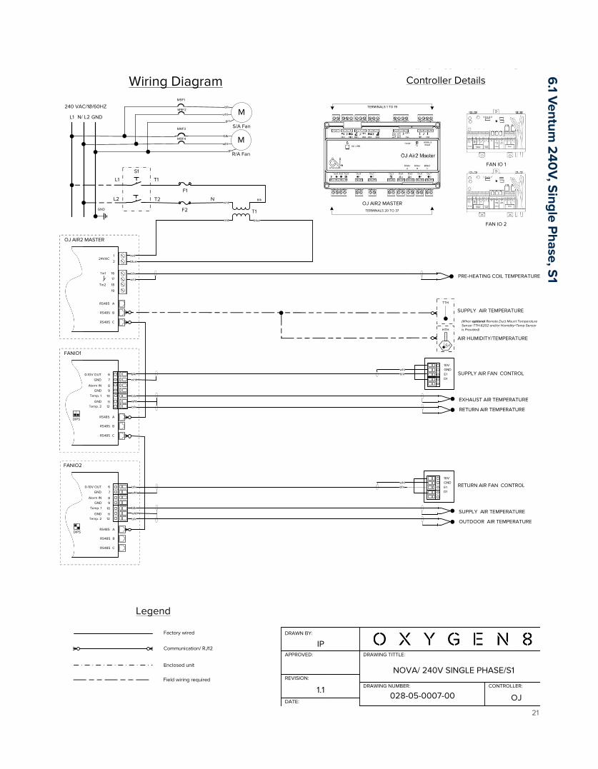
NOVA/ 240V SINGLE PHASE/S1
028-05-0007-00DATE:
1.1
REVISION:
CONTROLLER:
OJ
Controller DetailsWiring Diagram
1
OJ AIR2 MASTER
TERMINALS 20 TO 37
TERMINALS 1 TO 19
OJ AIR2 MASTER
224VAC
16
17
18
19
Tin1
Tin2
A
B
C
RS485
RS485
RS485
FAN IO 1
FAN IO 2
FANIO1
6
7
8
0-10V OUT
Alarm IN
A
B
C
RS485
RS485
RS485
FANIO2
9
10
1112
GND
GND
Temp. 1
GNDTemp. 2
6
7
8
0-10V OUT
Alarm IN
A
B
C
RS485
RS485
RS485
9
10
1112
GND
GND
Temp. 1
GNDTemp. 2
DIPS
DIPS
EXHAUST AIR TEMPERATURE
RETURN AIR TEMPERATURE
10VGNDE1D1
whtSUPPLY AIR FAN CONTROL
SUPPLY AIR TEMPERATURE
OUTDOOR AIR TEMPERATURE
10VGNDE1D1
whtRETURN AIR FAN CONTROL
Legend
Factory wired
Communication/ RJ12
Enclosed unit
Field wiring required
SUPPLY AIR TEMPERATURE
(When optional Remote Duct Mount Temperature Sensor TTH-6202 and/or Humidity+Temp Sensor is Provided)
TTH
PRE-HEATING COIL TEMPERATURE
HTH
AIR HUMIDITY/TEMPERATURE
240 VAC/1/60HZ
L1 N/ L2 GND
grn
blue
M
R/A Fan
M9F1
M
S/A FanM9F3
grn
M9F2
M9F4
F1
S1
T1
N
L1 T1
GND
blk
F2
L2 T2
6.1 V
entum 2
40V, S
ingle Phase, S
1

Installation Manual Ventum Series
22
DRAWING TITTLE:
DRAWING NUMBER:
SCALE: SIZE: SHEET:
DRAWN BY:
APPROVED:
IP
2021-10-05 NTS 8" x 11.5" 1 of 1
NOVA/ 240V SINGLE PHASE/ S2
028-05-0008-00DATE:
1.1
REVISION:
CONTROLLER:
OJ
Controller DetailsWiring Diagram
1
OJ AIR2 MASTER
TERMINALS 20 TO 37
TERMINALS 1 TO 19
OJ AIR2 MASTER
224VAC
16
17
18
19
Tin1
Tin2
A
B
C
RS485
RS485
RS485
FAN IO 1
FAN IO 2
FANIO1
6
7
8
0-10V OUT
Alarm IN
A
B
C
RS485
RS485
RS485
FANIO2
9
10
1112
GND
GND
Temp. 1
GNDTemp. 2
6
7
8
0-10V OUT
Alarm IN
A
B
C
RS485
RS485
RS485
9
10
1112
GND
GND
Temp. 1
GNDTemp. 2
DIPS
DIPS
EXHAUST AIR TEMPERATURE
RETURN AIR TEMPERATURE
10VGNDE1D1
wht
SUPPLY AIR FAN CONTROL
SUPPLY AIR TEMPERATURE
OUTDOOR AIR TEMPERATURE
10VGNDE1D1
wht
RETURN AIR FAN CONTROL
Legend
Factory wired
Communication/ RJ12
Enclosed unit
Field wiring required
PRE-HEATING COIL TEMPERATURE
SUPPLY AIR TEMPERATURE
(When optional Remote Duct Mount Temperature Sensor TTH-6202 and/or Humidity+Temp Sensor is Provided)
TTH
HTH
AIR HUMIDITY/TEMPERATURE
Wiring Diagram
240 VAC/1/60HZ
L1 N/ L2 GND
grn
blue
M
R/A Fan
M9F1
M
S/A FanM9F3
grn
M9F2
M9F4
F1
S1
T1
N
L1 T1
GND
blk
F2
L2 T2
6.2
Ventum
240
V, Single P
hase, S2
Installation Manual Ventum Series
23
DRAWING TITTLE:
DRAWING NUMBER:
SCALE: SIZE: SHEET:
DRAWN BY:
APPROVED:
IP
2021-04-05 NTS 8" x 11.5" 1 of 1
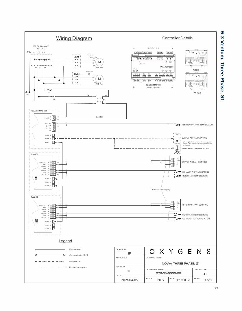
NOVA/ THREE PHASE/ S1
028-05-0009-00DATE:
1.0REVISION:
CONTROLLER:
OJ
Controller DetailsWiring Diagram
1
F1
208 OR 460 VAC/3 HZ
L1 L2
blk
M
R/A Fan
T1
24VAC
OJ AIR2 MASTER
N
L3
red
M
S/A Fanred
TERMINALS 20 TO 37
TERMINALS 1 TO 19
blk
OJ AIR2 MASTER
224VAC
16
17
18
19
Tin1
Tin2
A
B
C
RS485
RS485
RS485
FAN IO 1
FAN IO 2
FANIO1
6
7
8
0-10V OUT
Alarm IN
A
B
C
RS485
RS485
RS485
FANIO2
9
10
1112
GND
GND
Temp. 1
GNDTemp. 2
6
7
8
0-10V OUT
Alarm IN
A
B
C
RS485
RS485
RS485
9
10
1112
GND
GND
Temp. 1
GNDTemp. 2
blue
DIPS
DIPS
EXHAUST AIR TEMPERATURE
RETURN AIR TEMPERATURE
10VGNDE1D1
10VGNDE1D1
whtSUPPLY AIR FAN CONTROL
SUPPLY AIR TEMPERATURE
OUTDOOR AIR TEMPERATURE
10VGNDE1D1
10VGNDE1D1
whtRETURN AIR FAN CONTROL
Legend
Factory wired
Communication/ RJ12
Enclosed unit
Field wiring required
GND
GND
MDMD
T1 T2 T3
F2blk
MMP1MMP1
MMP2MMP2
grn
To Ground
grn
To Ground
Factory Jumper (blk)
PRE-HEATING COIL TEMPERATURE
SUPPLY AIR TEMPERATURE
(When optional Remote Duct Mount Temperature Sensor TTH-6202 and/or Humidity+Temp Sensor is Provided)
TTHTTH
HTHHTH
AIR HUMIDITY/TEMPERATURE
6.3 V
entum, Three P
hase, S1

Installation Manual Ventum Series
24
DRAWING TITTLE:
DRAWING NUMBER:
SCALE: SIZE: SHEET:
DRAWN BY:
APPROVED:
IP
2021-04-05 NTS 8" x 11.5" 1 of 1
NOVA/ THREE PHASE/ S2
028-05-0010-00DATE:
1.0REVISION:
CONTROLLER:
OJ
Controller DetailsWiring Diagram
1
F1
208 OR 460 VAC/3 HZ
L1 L2
blk
M
R/A Fan
T1
24VAC
OJ AIR2 MASTER
L3
red
M
S/A Fanred
TERMINALS 20 TO 37
TERMINALS 1 TO 19
blk
OJ AIR2 MASTER
224VAC
16
17
18
19
Tin1
Tin2
A
B
C
RS485
RS485
RS485
FAN IO 1
FAN IO 2
FANIO1
6
7
8
0-10V OUT
Alarm IN
A
B
C
RS485
RS485
RS485
FANIO2
9
10
1112
GND
GND
Temp. 1
GNDTemp. 2
6
7
8
0-10V OUT
Alarm IN
A
B
C
RS485
RS485
RS485
9
10
1112
GND
GND
Temp. 1
GNDTemp. 2
blue
DIPS
DIPS
10VGNDE1D1
10VGNDE1D1
wht
10VGNDE1D1
10VGNDE1D1
wht
Legend
Factory wired
Communication/ RJ12
Enclosed unit
Field wiring required
GND
GND
MDMD
T1 T2 T3
F2blk
MMP1MMP1
MMP2MMP2
grn
To Ground
grn
To Ground
Factory Jumper (blk)
EXHAUST AIR TEMPERATURE
RETURN AIR TEMPERATURE
SUPPLY AIR FAN CONTROL
SUPPLY AIR TEMPERATURE
OUTDOOR AIR TEMPERATURE
RETURN AIR FAN CONTROL
PRE-HEATING COIL TEMPERATURE
SUPPLY AIR TEMPERATURE
(When optional Remote Duct Mount Temperature Sensor TTH-6202 and/or Humidity+Temp Sensor is Provided)
TTHTTH
HTHHTH
AIR HUMIDITY/TEMPERATURE
6.4 V
entum, Three P
hase, S2

Installation Manual Ventum Series
25
DRAWING TITTLE:
DRAWING NUMBER:
SCALE: SIZE: SHEET:
DRAWN BY:
APPROVED:
IP
2021-09-30 NTS 8" x 11.5" 1 of 1
VENTUM/ FIELD WIRING/ DX COIL (w/EKE)
028-05-0019-00DATE:
1.0
REVISION:
CONTROLLER:
OJ
Controller DetailsWiring Diagram
1
T1
24VAC
OJ AIR2 MASTER
N
TERMINALS 20 TO 37
TERMINALS 1 TO 19
blk
OJ AIR2 MASTER
224VAC
16
17
18
19
Tin1
Tin2
A
B
C
RS485
RS485
RS485
Legend
Factory wired
Communication/ RJ12
Enclosed unit
Field wiring required
GNDGND
OUTDOOR UNIT PC BOARD
W CONTROLLER
Refer to standard wiring diagrams for panel wiring details.
20
21
22
23
Aout1
Aout2
Aout3
24
25Dout1
26
27Dout2
28
29Dout3
30
31Dout4
32
33Dout5
34
35Dout6
36
37Dout4
remocon
outdoor
ON
/OFF
errorop
eration0
-10 V
P1
P2
F1F2
T1T2
C1
C2
C3
C4
C5
C6
W C
ON
TRO
LLER
TERM
INA
L BLO
CK
C/H
SELECTO
R
AB
C
X1A
X1M
ON
OFF
DS1 (A1P)
A5P
AH
U O
UTD
OO
R
UN
IT
A
C
Set DS-1 Switch On and Power Reset
HEATING DEMAND
0-10 DX COIL CONTROL
FAN SWITCH ON/OFF
TTH
SUPPLY AIR TEMPERATURE
(When optional Remote Duct Mount Temperature Sensor TTH-6202 and/or Humidity+Temp HTH Sensor is Provided)HTH
AIR HUMIDITY/TEMPERATURE
6.5
Field Wiring, D
X C
oil, EKE

Installation Manual Ventum Series
26
DRAWING TITTLE:
DRAWING NUMBER:
SCALE: SIZE: SHEET:
DRAWN BY:
APPROVED:
IP
2021-09-30 NTS 8" x 11.5" 1 of 1
VENTUM/ FIELD WIRING/ DX COIL/ ELEC. RE-HEAT (w/EKE)
028-05-0019-01DATE:
1.0
REVISION:
CONTROLLER:
OJ
Controller DetailsWiring Diagram
1
T1
24VAC
OJ AIR2 MASTER
N
TERMINALS 20 TO 37
TERMINALS 1 TO 19
blk
OJ AIR2 MASTER
224VAC
16
17
18
19
Tin1
Tin2
A
B
C
RS485
RS485
RS485
LegendFactory wired
Communication/ RJ12
Enclosed unit
Field wiring required
GNDGND
OUTDOOR UNIT PC BOARD
W CONTROLLER
Refer to standard wiring diagrams for panel wiring details.
20
21
22
23
Aout1
Aout2
Aout3
24
25Dout1
26
27Dout2
28
29Dout3
30
31Dout4
32
33Dout5
34
35Dout6
36
37Dout4
remocon
outdoorO
N/O
FFerror
operatio
n0
-10 V
P1P2
F1F2
T1T2
C1
C2
C3
C4
C5
C6
W C
ON
TRO
LLER
TERM
INA
L BLO
CK
C/H
SELEC
TOR
AB
C
X1A
X1M
ON
OFF
DS1 (A1P)
A5P
AH
U O
UTD
OO
R
UN
IT
A
C
Set DS-1 Switch On and Power Reset
FAN SWITCH
0-10 DX COIL CONTROL
SC
R
CO
NTR
OL
D21-PSSR OR D35
-
+
0-10 V input
+
GND RE-HEAT CONTROL
FAN SWITCH ON/OFF
HEATING DEMAND
TTH
SUPPLY AIR TEMPERATURE
(When optional Remote Duct Mount Temperature Sensor TTH-6202 and/or Humidity+Temp HTH Sensor is Provided)HTH
AIR HUMIDITY/TEMPERATURE
6.6
Field Wiring, D
X C
oil, Electric Re-H
eat, EKE

Installation Manual Ventum Series
27
DRAWING TITTLE:
DRAWING NUMBER:
SCALE: SIZE: SHEET:
DRAWN BY:
APPROVED:
IP
2021-09-30 NTS 8" x 11.5" 1 of 1
VENTUM/ FIELD WIRING/ELEC. PRE-HEAT/ DX COIL/ELEC. RE-HEAT (w/EKE)
028-05-0019-02DATE:
1.0
REVISION:
CONTROLLER:
OJ
Controller DetailsWiring Diagram
1
T1
24VAC
OJ AIR2 MASTER
N
TERMINALS 20 TO 37
TERMINALS 1 TO 19
blk
OJ AIR2 MASTER
224VAC
16
17
18
19
Tin1
Tin2
A
B
C
RS485
RS485
RS485
Legend
Factory wired
Communication/ RJ12
Enclosed unit
Field wiring required
GNDGND
OUTDOOR UNIT PC BOARD
W CONTROLLER
Refer to standard wiring diagrams for panel wiring details.
20
21
22
23
Aout1
Aout2
Aout3
24
25Dout1
26
27Dout2
28
29Dout3
30
31Dout4
32
33Dout5
34
35Dout6
36
37Dout4
remocon
outdoorO
N/O
FFerror
operatio
n0
-10 V
P1P2
F1F2
T1T2
C1
C2
C3
C4
C5
C6
W C
ON
TRO
LLER
TERM
INA
L BLO
CK
C/H
SELEC
TOR
AB
C
X1A
X1M
ON
OFF
DS1 (A1P)
A5P
AH
U O
UTD
OO
R
UN
IT
A
C
Set DS-1 Switch On and Power Reset
FAN SWITCH
0-10 DX COIL CONTROL
SC
R
CO
NTR
OL
D21-PSSR OR D35
-
+
0-10 V input
+
GND
SC
R
CO
NTR
OL
D21-PSSR OR D35
-
+
0-10 V input
RE-HEAT CONTROL
FAN SWITCH ON/OFF
GND PRE-HEAT CONTROL
HEATING DEMAND
TTH
SUPPLY AIR TEMPERATURE
(When optional Remote Duct Mount Temperature Sensor TTH-6202 and/or Humidity+Temp HTH Sensor is Provided)HTH
AIR HUMIDITY/TEMPERATURE
6.7 Field W
iring, Electric Pre-H
eat, DX
Coil, Electric R
e-Heat, EK
E

Installation Manual Ventum Series
28
DRAWING TITTLE:
DRAWING NUMBER:
SCALE: SIZE: SHEET:
DRAWN BY:
APPROVED:
IP
2021-09-30 NTS 8" x 11.5" 1 of 1
VENTUM/ FIELD WIRING/ELEC. PRE-HEAT/ DX COIL (w/EKE)
028-05-0019-03DATE:
1.0
REVISION:
CONTROLLER:
OJ
Controller DetailsWiring Diagram
1
T1
24VAC
OJ AIR2 MASTER
N
TERMINALS 20 TO 37
TERMINALS 1 TO 19
blk
OJ AIR2 MASTER
224VAC
16
17
18
19
Tin1
Tin2
A
B
C
RS485
RS485
RS485
Legend
Factory wired
Communication/ RJ12
Enclosed unit
Field wiring required
GNDGND
OUTDOOR UNIT PC BOARD
W CONTROLLER
Refer to standard wiring diagrams for panel wiring details.
20
21
22
23
Aout1
Aout2
Aout3
24
25Dout1
26
27Dout2
28
29Dout3
30
31Dout4
32
33Dout5
34
35Dout6
36
37Dout4
remocon
outdoorO
N/O
FFerror
operatio
n0
-10 V
P1P2
F1F2
T1T2
C1
C2
C3
C4
C5
C6
W C
ON
TRO
LLER
TERM
INA
L BLO
CK
C/H
SELEC
TOR
AB
C
X1A
X1M
ON
OFF
DS1 (A1P)
A5P
AH
U O
UTD
OO
R
UN
IT
A
C
Set DS-1 Switch On and Power Reset
FAN SWITCH
0-10 DX COIL CONTROL
SC
R
CO
NTR
OL
D21-PSSR OR D35
-
+
0-10 V input
FAN SWITCH ON/OFF
GND PRE-HEAT CONTROL
HEATING DEMAND
TTH
SUPPLY AIR TEMPERATURE
(When optional Remote Duct Mount Temperature Sensor TTH-6202 and/or Humidity+Temp HTH Sensor is Provided)HTH
AIR HUMIDITY/TEMPERATURE
6.8
Field Wiring, Electric P
re-Heat, D
X C
oil, EKE

Installation Manual Ventum Series
29
DRAWING TITTLE:
DRAWING NUMBER:
SCALE: SIZE: SHEET:
DRAWN BY:
APPROVED:
IP
2021-09-30 NTS 8" x 11.5" 1 of 1
VENTUM/ FIELD WIRING/ DAMPERS (ON/OFF)
028-05-0020-00DATE:
1.0
REVISION:
CONTROLLER:
OJ
Controller DetailsWiring Diagram
1
T1
24VAC
OJ AIR2 MASTER
N
TERMINALS 20 TO 37
TERMINALS 1 TO 19
blk
OJ AIR2 MASTER
224VAC
16
17
18
19
Tin1
Tin2
A
B
C
RS485
RS485
RS485
Legend
Factory wired
Communication/ RJ12
Enclosed unit
Field wiring required
GNDGND
Refer to standard wiring diagrams for panel wiring details.
20
21
22
23
Aout1
Aout2
Aout3
24
25Dout1
26
27Dout2
28
29Dout3
30
31Dout4
32
33Dout5
34
35Dout6
36
37Dout4
DAMPER ACTUATOR
12
13
14
15
Ain1Ain2
+24V
COMMON
+ HOT
Blk (1)
Wht (2)wht
OUTDOOR AIR DAMPERLF TYPE
COMMON
+ HOT
Blk (1)
Wht (2)
EXHAUST AIR DAMPERLF TYPE
wht
TTH
SUPPLY AIR TEMPERATURE
(When optional Remote Duct Mount Temperature Sensor TTH-6202 and/or Humidity+Temp HTH Sensor is Provided)HTH
AIR HUMIDITY/TEMPERATURE
6.9
Field Wiring, D
amper W
iring

Installation Manual Ventum Series
30
DRAWING TITTLE:
DRAWING NUMBER:
SCALE: SIZE: SHEET:
DRAWN BY:
APPROVED:
IP
2021-09-30 NTS 8" x 11.5" 1 of 1
VENTUM/ FIELD WIRING /ELECTRIC RE-HEAT
028-05-0020-01DATE:
1.0
REVISION:
CONTROLLER:
OJ
Controller DetailsWiring Diagram
1
T1
24VAC
OJ AIR2 MASTER
N
TERMINALS 20 TO 37
TERMINALS 1 TO 19
blk
OJ AIR2 MASTER
224VAC
16
17
18
19
Tin1
Tin2
A
B
C
RS485
RS485
RS485
Legend
Factory wired
Communication/ RJ12
Enclosed unit
Field wiring required
GNDGND
Refer to standard wiring diagrams for panel wiring details.
20
21
22
23
Aout1
Aout2
Aout3
24
25Dout1
26
27Dout2
28
29Dout3
30
31Dout4
32
33Dout5
34
35Dout6
36
37Dout4
SC
R
CO
NTR
OL
D21-PSSR OR D35
-
+
0-10 V input+
GND RE-HEAT CONTROL
SSR HEATER
NOTE: Refer to standard wiring diagrams for default controls wiring.
TTH
SUPPLY AIR TEMPERATURE
(When optional Remote Duct Mount Temperature Sensor TTH-6202 and/or Humidity+Temp HTH Sensor is Provided)HTH
AIR HUMIDITY/TEMPERATURE
6.10
Field Wiring, Electric R
eheat Wiring

Installation Manual Ventum Series
31
DRAWING TITTLE:
DRAWING NUMBER:
SCALE: SIZE: SHEET:
DRAWN BY:
APPROVED:
IP
2021-09-30 NTS 8" x 11.5" 1 of 1
VENTUM/ FIELD/ ELECTRIC PRE-HEAT/ ELECTRIC RE-HEAT
028-05-0020-02DATE:
1.0
REVISION:
CONTROLLER:
OJ
Controller DetailsWiring Diagram
1
T1
24VAC
OJ AIR2 MASTER
N
TERMINALS 20 TO 37
TERMINALS 1 TO 19
blk
OJ AIR2 MASTER
224VAC
16
17
18
19
Tin1
Tin2
A
B
C
RS485
RS485
RS485
Legend
Factory wired
Communication/ RJ12
Enclosed unit
Field wiring required
GNDGND
Refer to standard wiring diagrams for panel wiring details.
20
21
22
23
Aout1
Aout2
Aout3
24
25Dout1
26
27Dout2
28
29Dout3
30
31Dout4
32
33Dout5
34
35Dout6
36
37Dout4 S
CR
C
ON
TRO
L
D21-PSSR OR D35
-
+
0-10 V input+
GND
SC
R
CO
NTR
OL
D21-PSSR OR D35
-
+
0-10 V input
RE-HEAT CONTROL
GND PRE-HEAT CONTROL
SSR HEATER
NOTE: Refer to standard wiring diagrams for default controls wiring.
TTH
SUPPLY AIR TEMPERATURE
(When optional Remote Duct Mount Temperature Sensor TTH-6202 and/or Humidity+Temp HTH Sensor is Provided)HTH
AIR HUMIDITY/TEMPERATURE
6.11 Field W
iring, Electric Preheat, Electric R
eheat Wiring

Installation Manual Ventum Series
32
DRAWING TITTLE:
DRAWING NUMBER:
SCALE: SIZE: SHEET:
DRAWN BY:
APPROVED:
IP
2021-09-30 NTS 8" x 11.5" 1 of 1
VENTUM/ FIELD WIRING/ELECTRIC PRE-HEAT
028-05-0020-03DATE:
1.0
REVISION:
CONTROLLER:
OJ
Controller DetailsWiring Diagram
1
T1
24VAC
OJ AIR2 MASTER
N
TERMINALS 20 TO 37
TERMINALS 1 TO 19
blk
OJ AIR2 MASTER
224VAC
16
17
18
19
Tin1
Tin2
A
B
C
RS485
RS485
RS485
Legend
Factory wired
Communication/ RJ12
Enclosed unit
Field wiring required
GNDGND
Refer to standard wiring diagrams for panel wiring details.
20
21
22
23
Aout1
Aout2
Aout3
24
25Dout1
26
27Dout2
28
29Dout3
30
31Dout4
32
33Dout5
34
35Dout6
36
37Dout4
SC
R
CO
NTR
OL
D21-PSSR OR D35
-
+
0-10 V input
GND PRE-HEAT CONTROL
SSR HEATER
NOTE: Refer to standard wiring diagrams for default controls wiring.
TTH
SUPPLY AIR TEMPERATURE
(When optional Remote Duct Mount Temperature Sensor TTH-6202 and/or Humidity+Temp HTH Sensor is Provided)HTH
AIR HUMIDITY/TEMPERATURE
6.12
Field Wiring, Electric P
reheat Wiring

Installation Manual Ventum Series
33
DRAWING TITTLE:
DRAWING NUMBER:
SCALE: SIZE: SHEET:
DRAWN BY:
APPROVED:
DATE:
REVISION:
CONTROLLER:
IP
2021-09-30 NTS 8" x 11.5" 1 of 1
028-05-0020-041.0
OJ
Controller DetailsWiring Diagram
T1
24VAC
N
TERMINALS 20 TO 37
TERMINALS 1 TO 19
blk
OJ AIR2 MASTER
0
Legend
Factory wired
Communication/ RJ12
Enclosed unit
Field wiring required
TTH
GNDGND
SUPPLY AIR TEMPERATURE
Refer to standard wiring diagrams for panel wiring details.
COOLING VALVE ACTUATOR
VENTUM/ FIELD WIRING/HYDRONIC COOLING WATER COIL
NOTE: Refer to standard wiring diagrams for default controls wiring.
VALVE ACTUATOR
MG0G
YM
UZ
1
OJ AIR2 MASTER
224VAC
16
17
18
19
Tin1
Tin2
A
B
C
RS485
RS485
RS485
20
21
22
23
Aout1
Aout2
Aout3
24
25Dout1
26
27Dout2
28
29Dout3
30
31Dout4
32
33Dout5
34
35Dout6
36
37Dout4
12
13
14
15
Ain1Ain2
+24V
POSITION SIGNAL 0-10 VDC/ 4-20 mA
(When optional Remote Duct Mount Temperature Sensor TTH-6202 and/or Humidity+Temp Sensor is Provided)
HTH
AIR HUMIDITY/TEMPERATURE
6.13 Field W
iring, Hydronic C
ooling Water C
oil
Installation Manual Ventum Series
34
DRAWING TITTLE:
DRAWING NUMBER:
SCALE: SIZE: SHEET:
DRAWN BY:
APPROVED:
DATE:
REVISION:
CONTROLLER:
IP
2021-09-30 NTS 8" x 11.5" 1 of 1
028-05-0020-051.0
OJ
Controller DetailsWiring Diagram
T1
24VAC
N
TERMINALS 20 TO 37
TERMINALS 1 TO 19
blk
OJ AIR2 MASTER
Legend
Factory wired
Communication/ RJ12
Enclosed unit
Field wiring required
GNDGND
Refer to standard wiring diagrams for panel wiring details.
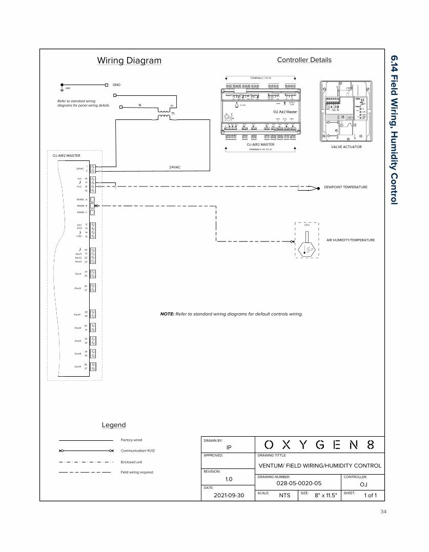
VENTUM/ FIELD WIRING/HUMIDITY CONTROL
NOTE: Refer to standard wiring diagrams for default controls wiring.
VALVE ACTUATOR
1
OJ AIR2 MASTER
224VAC
16
17
18
19
Tin1
Tin2
A
B
C
RS485
RS485
RS485
20
21
22
23
Aout1
Aout2
Aout3
24
25Dout1
26
27Dout2
28
29Dout3
30
31Dout4
32
33Dout5
34
35Dout6
36
37Dout4
12
13
14
15
Ain1Ain2
+24V
HTH
AIR HUMIDITY/TEMPERATURE
DEWPOINT TEMPERATURE
6.14 Field W
iring, Hum
idity Control
Installation Manual Ventum Series
35
DRAWING TITTLE:
DRAWING NUMBER:
SCALE: SIZE: SHEET:
DRAWN BY:
APPROVED:
DATE:
REVISION:
CONTROLLER:
IP
2021-09-30 NTS 8" x 11.5" 1 of 1
028-05-0020-061.0
OJ
Controller DetailsWiring Diagram
T1
24VAC
N
TERMINALS 20 TO 37
TERMINALS 1 TO 19
blk
OJ AIR2 MASTER
0
Legend
Factory wired
Communication/ RJ12
Enclosed unit
Field wiring required
GNDGND
Refer to standard wiring diagrams for panel wiring details.
COMBI-COIL VALVE ACTUATOR
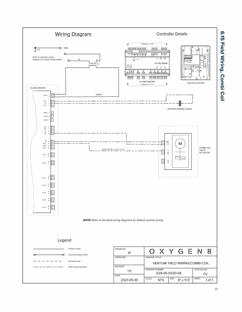
VENTUM/ FIELD WIRING/COMBI-COIL
NOTE: Refer to standard wiring diagrams for default controls wiring.
VALVE ACTUATOR
MG0G
YM
UZ
1
OJ AIR2 MASTER
224VAC
3
4
5
Din1
Din2
A
B
C
RS485
RS485
RS485
20
21
22
23
Aout1
Aout2
Aout3
24
25Dout1
26
27Dout2
28
29Dout3
30
31Dout4
32
33Dout5
34
35Dout6
36
37Dout4
12
13
14
15
Ain1Ain2
+24V
POSITION SIGNAL 0-10 VDC/ 4-20 mA
HEATING DEMAND SIGNAL
6.15
Field Wiring, C
ombi C
oil

Installation Manual Ventum Series
36
DRAWING TITTLE:
DRAWING NUMBER:
SCALE: SIZE: SHEET:
DRAWN BY:
APPROVED:
IP
2021-09-30 NTS 8" x 11.5" 1 of 1
VENTUM/ FIELD WIRING/HYDRONIC PRE-HEAT
028-05-0020-07DATE:
1.1
REVISION:
CONTROLLER:
OJ
Controller DetailsWiring Diagram
T1
24VAC
TERMINALS 20 TO 37
TERMINALS 1 TO 19
blk
OJ AIR2 MASTER
Legend
Factory wired
Communication/ RJ12
Enclosed unit
Field wiring required
GNDGND
Refer to standard wiring diagrams for panel wiring details.
GND
NOTE: Refer to standard wiring diagrams for default controls wiring.
PRE-HEAT COIL RETURN WATER TEMP.
1
OJ AIR2 MASTER
224VAC
16
17
18
19
Tin1
Tin2
A
B
C
RS485
RS485
RS485
20
21
22
23
Aout1
Aout2
Aout3
24
25Dout1
26
27Dout2
28
29Dout3
30
31Dout4
32
33Dout5
34
35Dout6
36
37Dout4
12
13
14
15
Ain1Ain2
+24V
PRE-HEAT CONTROLVALVE
MG0G
YM
UZ
VALVE CONTROL 0-10 VDC
+ 24 VDC
VALVE ACTUATOR
6.16
Field Wiring, H
ydronic Pre-H
eat
Installation Manual Ventum Series
37
DRAWING TITTLE:
DRAWING NUMBER:
SCALE: SIZE: SHEET:
DRAWN BY:
APPROVED:
DATE:
REVISION:
CONTROLLER:
IP
2021-09-30 NTS 8" x 11.5" 1 of 1
028-05-0020-081.0
OJ
Controller DetailsWiring Diagram
T1
24VAC
N
TERMINALS 20 TO 37
TERMINALS 1 TO 19
blk
OJ AIR2 MASTER
Legend
Factory wired
Communication/ RJ12
Enclosed unit
Field wiring required
GNDGND
Refer to standard wiring diagrams for panel wiring details.
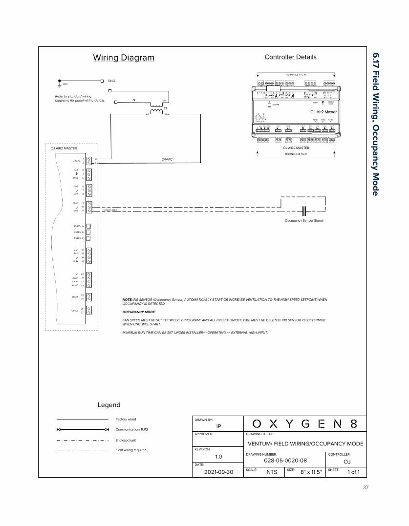
VENTUM/ FIELD WIRING/OCCUPANCY MODE
NOTE: PIR SENSOR (Occupancy Sensor) AUTOMATICALLY START OR INCREASE VENTILATION TO THE HIGH SPEED SETPOINT WHEN OCCUPANCY IS DETECTED.
OCCUPANCY MODE:
FAN SPEED MUST BE SET TO “WEEKLY PROGRAM” AND ALL PRESET ON/OFF TIME MUST BE DELETED. PIR SENSOR TO DETERMINE WHEN UNIT WILL START.
MINIMUM RUN TIME CAN BE SET UNDER INSTALLER=> OPERATING => EXTERNAL HIGH INPUT.
1
OJ AIR2 MASTER
224VAC
3
4
5
Din1
Din2
A
B
C
RS485
RS485
RS485
20
21
22
23
Aout1
Aout2
Aout3
24
25Dout1
26
27Dout2
12
13
14
15
Ain1Ain2
+24V
Occupancy Sensor Signal
6
7
8
Din3
Din4
9
10
11
Din5
Din6 HIGH SPEED
6.17 Field W
iring, Occupancy M
ode
Installation Manual Ventum Series
38
DRAWING TITTLE:
DRAWING NUMBER:
SCALE: SIZE: SHEET:
DRAWN BY:
APPROVED:
IP
2021-09-30 NTS 8" x 11.5" 1 of 1
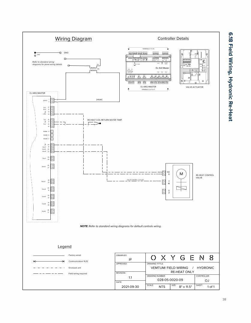
VEMTUM/ FIELD WIRING / HYDRONIC RE-HEAT ONLY
028-05-0020-09DATE:
1.1
REVISION:
CONTROLLER:
OJ
Controller DetailsWiring Diagram
T1
24VAC
TERMINALS 20 TO 37
TERMINALS 1 TO 19
blk
OJ AIR2 MASTER
Legend
Factory wired
Communication/ RJ12
Enclosed unit
Field wiring required
GNDGND
Refer to standard wiring diagrams for panel wiring details.
GND
NOTE: Refer to standard wiring diagrams for default controls wiring.
RE-HEAT COIL RETURN WATER TEMP.
1
OJ AIR2 MASTER
224VAC
16
17
18
19
Tin1
Tin2
A
B
C
RS485
RS485
RS485
20
21
22
23
Aout1
Aout2
Aout3
24
25Dout1
26
27Dout2
28
29Dout3
30
31Dout4
32
33Dout5
34
35Dout6
36
37Dout4
12
13
14
15
Ain1Ain2
+24V
RE-HEAT CONTROLVALVE
MG0G
YM
UZ
VALVE CONTROL 0-10 VDC
+ 24 VDC
VALVE ACTUATOR
6.18
Field Wiring, H
ydronic Re-H
eat

Installation Manual Ventum Series
39
DRAWING TITTLE:
DRAWING NUMBER:
SCALE: SIZE: SHEET:
DRAWN BY:
APPROVED:
DATE:
REVISION:
CONTROLLER:
IP
2021-09-30 NTS 8" x 11.5" 1 of 1
028-05-0020-101.0
OJ
Controller DetailsWiring Diagram
T1
24VAC
N
TERMINALS 20 TO 37
TERMINALS 1 TO 19
blk
OJ AIR2 MASTER
Legend
Factory wired
Communication/ RJ12
Enclosed unit
Field wiring required
GNDGND
Refer to standard wiring diagrams for panel wiring details.
VENTUM/ FIELD WIRING/FIRE ALARM
FIRE ALARM SEQUENCE: FIRE ALARM SIGNAL IS NORMALLY CLOSED CONTACT. IN THE EVENT OF FIRE, CONTACT OPENS AND UNIT IS SHUT DOWN. AN “EXTERNAL FIRE” ALARM WILL BE DISPLAYED ON HMI.
1
OJ AIR2 MASTER
224VAC
3
4
5
Din1
Din2
A
B
C
RS485
RS485
RS485
20
21
22
23
Aout1
Aout2
Aout3
24
25Dout1
26
27Dout2
12
13
14
15
Ain1Ain2
+24V
Fire Alarm Signal (NC)
6
7
8
Din3
Din4
9
10
11
Din5
Din6
EXTERNAL FIRE THERMOSTAT (STOP)
6.19
Field Wiring, Fire A
larm

Installation Manual Ventum Series
40
DRAWING TITTLE:
DRAWING NUMBER:
SCALE: SIZE: SHEET:
DRAWN BY:
APPROVED:
IP
2021-09-29 NTS 8" x 11.5" 1 of 2
VENTUM/ FIELD WIRING/ DX COIL/ HYDRONIC RE-HEAT (w/EKE)+ HEAT RECOVERY
CUSTOM210929DATE:
1.0
REVISION:
CONTROLLER:
OJ
Controller DetailsWiring Diagram
1
T1
24VAC
OJ AIR2 MASTER
N
TERMINALS 20 TO 37
TERMINALS 1 TO 19
blk
OJ AIR2 MASTER
224VAC
16
17
18
19
Tin1
Tin2
A
B
C
RS485
RS485
RS485
LegendFactory wired
Communication/ RJ12
Enclosed unit
Field wiring required
GNDGND
OUTDOOR UNIT PC BOARD
W CONTROLLER
Refer to standard wiring diagrams for panel wiring details.
20
21
22
23
Aout1
Aout2
Aout3
24
25Dout1
26
27Dout2
28
29Dout3
30
31Dout4
32
33Dout5
34
35Dout6
36
37Dout4
remocon
outdoorO
N/O
FFerror
operatio
n0
-10 V
P1P2
F1F2
T1T2
C1
C2
C3
C4
C5
C6
W C
ON
TRO
LLER
TERM
INA
L BLO
CK
C/H
SELEC
TOR
AB
C
X1A
X1M
ON
OFF
DS1 (A1P)
A5P
AH
U O
UTD
OO
R
UN
IT
A
C
Set DS-1 Switch On and Power Reset
FAN SWITCH
0-10 DX COIL CONTROL
FAN SWITCH ON/OFF
HEATING DEMAND
TTH
SUPPLY AIR TEMPERATURE
(When optional Remote Duct Mount Temperature Sensor TTH-6202 and/or Humidity+Temp HTH Sensor is Provided)HTH
AIR HUMIDITY/TEMPERATURE
RE-HEAT COIL WATER TEMP.
20 22 23
12
13
14
15
Ain1Ain2
+24V
14
15BYPASS & RE-HEAT VALVE POWER (SEE PAGE 2)
TO PAGE 2
RE-HEAT CONTROL
BYPASS CONTROL
6.2
0 Field W
iring, DX
Coil, H
ydronic Coil, EK
E, Bypass

Installation Manual Ventum Series
41
DRAWING TITTLE:
DRAWING NUMBER:
SCALE: SIZE: SHEET:
DRAWN BY:
APPROVED:
IP
2021-09-30 NTS 8" x 11.5" 1 of 1
VENTUM/ FIELD WIRING/CO2 CONTROL+ EXTERNAL BYPASS
CUSTOM210930DATE:
1.1
REVISION:
CONTROLLER:
OJ
Controller DetailsWiring Diagram
1
T1
24VAC
OJ AIR2 MASTER
N
TERMINALS 20 TO 37
TERMINALS 1 TO 19
blk
OJ AIR2 MASTER
224VAC
16
17
18
19
Tin1
Tin2
A
B
C
RS485
RS485
RS485
Legend
Factory wired
Communication/ RJ12
Enclosed unit
Field wiring required
GNDGND
Refer to standard wiring diagrams for panel wiring details.
20
21
22
23
Aout1
Aout2
Aout3
24
25Dout1
26
27Dout2
28
29Dout3
30
31Dout4
32
33Dout5
34
35Dout6
36
37Dout4
DAMPER ACTUATOR
12
13
14
15
Ain1Ain2
+24V
VTH
CO2 SENSOR
VTH-6202 SENSOR TO BE INSTALLED IN RETURN AIR DUCT.
CO2
TO FANIO 1 EXT. PORT.(See Standard Wiring Diagram)
COMMON
+ HOT
Blk (1)
Red (2)
Y1 INPUT
Y2 INPUT
Wht (1)
Wht (2)
U OUTPUTWht (2)
0-10 VDCBYPASS CONTROL 0-10 VDC/ HEAT RECOVERY
COMMON
+ HOT
Blk (1)
Red (2) BYPASS DAMPER 1MTF TYPE - NO
Y1 INPUT
Y2 INPUT
Wht (1)
Wht (2)
U OUTPUTWht (2)
wht
0-10 VDC
BYPASS CONTROL 0-10 VDC/ HEAT RECOVERY
BYPASS DAMPER 2MTF TYPE - NC
6.2
1 Field Wiring, C
O2
Control, External B
ypass