Bulletin 30-20 / Dec. 2010
© Copyright 2010 Unico, Inc.
INSTALLATION MANUAL
FOR
‘M’ SERIES MODULAR AIR HANDLER UNITS
IL00004a.CVN
GENERAL
The information on the following pages is to help the installer save time, provide the best possible installation and ensure continuous trouble-free operation.
SCOPE
These instructions apply to the Unico “M” Series mod-ular air handler units. For heat pumps, refer to Bulletin 30-24 for additional instructions. Installation instructions for the air distribution system are covered in Bulletin 30-05. Before beginning any installation a detailed system layout must be done in accordance with the System Siz-ing and Layout Procedure, Bulletin 40-40 and the Com-ponent Layout Instructions, Bulletin 40-30.
NOTICE TO INSTALLER AND EQUIPMENT OWNER: RETAIN THIS MANUAL AT THE JOB.
FULL BUILDING INSULATION IS ESSENTIAL FOR THE MOST ECONOMICAL OPERATION
GENERAL PRECAUTIONS AND SAFETY TIPS
Do not attempt to install or startup unit without first reading and understanding the appropriate sections in this manual.
Before operating, be sure the unit is properly grounded.
Installation should be in accordance with all local codes and regulations and with the National Board of Fire Un-derwriters regulations. In case of conflict, local codes take precedence.
All electrical wiring should be in accordance with the latest edition of the National Electrical Code and all lo-cal codes and regulations. The unit is safety certified to UL 1995 and listed with ETL.
Always install a secondary drain pan when an overflow of condensate could cause damage.
PART NUMBERS
This manual does not always include the latest revision letter when referring to UPC part numbers. Refer to the latest Price List and Spec Sheets for the current UPC revision letter. For example, in UPC-00x the ‘x’ indi-cates the latest revision.
INTRODUCTION
The Unico System is a complete indoor comfort system that includes an indoor air handling unit and small duct system. The air handler and duct system were designed to operate together to provide the proper airflow in every installation. The conditioned air is supplied through a series of 2-inch ducts as a stream of air that entrains and mixes the room air. This process of aspiration produces a more even temperature distribution in the room.
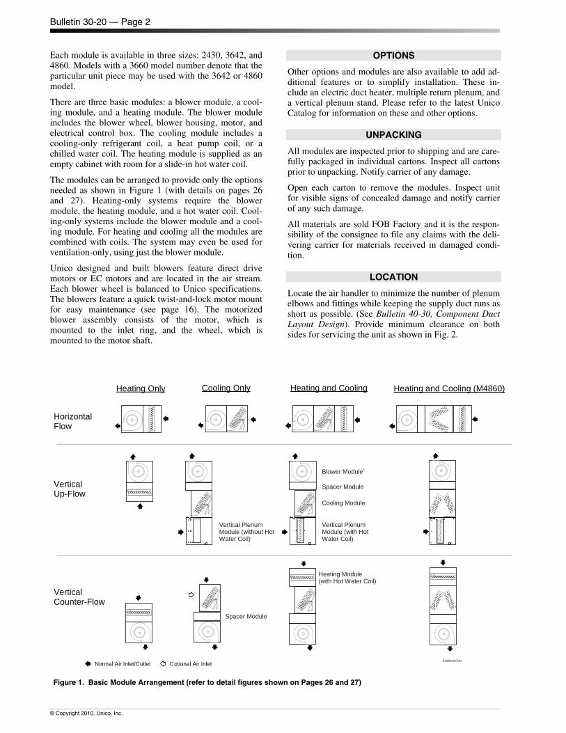
The Unico 'M' Modular Series air-handling units consist of various modules that are easily latched together. The modules can be arranged in a vertical-up-flow, vertical-counter-flow and horizontal-flow configuration. They can be combined as a heating-only, cooling-only, or heating and cooling air handler unit. See Fig. 1.
All insulated Unico System modules feature closed-cell insulation for improved sound attenuation. There is no exposed fiberglass insulation.
TABLE OF CONTENTS INTRODUCTION ................................................................... 1 OPTIONS ............................................................................. 2 UNPACKING ......................................................................... 2 LOCATION ............................................................................ 3 UNIT ASSEMBLY .................................................................. 4
Anti-Frost Switch Wires .................................................. 4 Fastening Modules Together .......................................... 4 EC Motor Temperature Operating Limits ......................... 4 Horizontal Installation ..................................................... 4 Vertical Installation ......................................................... 5 Control Box ..................................................................... 7 Secondary Drain Pan ..................................................... 7
MOUNTING ........................................................................... 8 Horizontal Platform Mounting ......................................... 8 Horizontal Suspended Mounting ..................................... 8 Vertical ........................................................................... 8
DUCT CONNECTIONS ........................................................ 9 Supply Plenum ............................................................. 10 Return Duct .................................................................. 10 Multiple Returns ............................................................ 10
PIPING ................................................................................ 10 Condensate Lines ........................................................ 10 Refrigerant Lines .......................................................... 11 Water Connections ....................................................... 13 Coil Cleaning ................................................................ 13
WIRING ............................................................................... 13 Ventilation Speed Mode ............................................... 14
STARTUP ............................................................................ 21 Sequence of Operation ................................................. 21 Checking Airflow ........................................................... 21 Charging the System .................................................... 23 Low Ambient Control Kit ............................................... 24
R-410A Refrigerant ............................................................. 24 Maintenance ....................................................................... 25 Module Configuration Illustrations ........................................ 26
Bulletin 30-20 — Page 2
© Copyright 2010, Unico, Inc.
Each module is available in three sizes: 2430, 3642, and 4860. Models with a 3660 model number denote that the particular unit piece may be used with the 3642 or 4860 model.
There are three basic modules: a blower module, a cool-ing module, and a heating module. The blower module includes the blower wheel, blower housing, motor, and electrical control box. The cooling module includes a cooling-only refrigerant coil, a heat pump coil, or a chilled water coil. The heating module is supplied as an empty cabinet with room for a slide-in hot water coil.
The modules can be arranged to provide only the options needed as shown in Figure 1 (with details on pages 26 and 27). Heating-only systems require the blower module, the heating module, and a hot water coil. Cool-ing-only systems include the blower module and a cool-ing module. For heating and cooling all the modules are combined with coils. The system may even be used for ventilation-only, using just the blower module.
Unico designed and built blowers feature direct drive motors or EC motors and are located in the air stream. Each blower wheel is balanced to Unico specifications. The blowers feature a quick twist-and-lock motor mount for easy maintenance (see page 16). The motorized blower assembly consists of the motor, which is mounted to the inlet ring, and the wheel, which is mounted to the motor shaft.
OPTIONS
Other options and modules are also available to add ad-ditional features or to simplify installation. These in-clude an electric duct heater, multiple return plenum, and a vertical plenum stand. Please refer to the latest Unico Catalog for information on these and other options.
UNPACKING
All modules are inspected prior to shipping and are care-fully packaged in individual cartons. Inspect all cartons prior to unpacking. Notify carrier of any damage.
Open each carton to remove the modules. Inspect unit for visible signs of concealed damage and notify carrier of any such damage.
All materials are sold FOB Factory and it is the respon-sibility of the consignee to file any claims with the deli-vering carrier for materials received in damaged condi-tion.
LOCATION
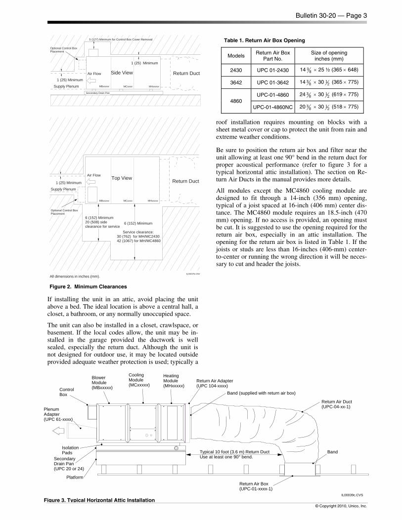
Locate the air handler to minimize the number of plenum elbows and fittings while keeping the supply duct runs as short as possible. (See Bulletin 40-30, Component Duct Layout Design). Provide minimum clearance on both sides for servicing the unit as shown in Fig. 2.
Heating and Cooling
HorizontalFlow
VerticalCounter-Flow
VerticalUp-Flow
IL00010d.CVN
Heating Only Cooling Only
Normal Air Inlet/Outlet Optional Air Inlet
Blower Module`
Spacer Module
Cooling Module
Vertical PlenumModule (with HotWater Coil)
Vertical PlenumModule (without HotWater Coil)
Spacer Module
Heating Module(with Hot Water Coil)
Heating and Cooling (M4860)
Figure 1. Basic Module Arrangement (refer to detail figures shown on Pages 26 and 27)
Bulletin 30-20 — Page 3
© Copyright 2010, Unico, Inc.
If installing the unit in an attic, avoid placing the unit above a bed. The ideal location is above a central hall, a closet, a bathroom, or any normally unoccupied space.
The unit can also be installed in a closet, crawlspace, or basement. If the local codes allow, the unit may be in-stalled in the garage provided the ductwork is well sealed, especially the return duct. Although the unit is not designed for outdoor use, it may be located outside provided adequate weather protection is used; typically a
roof installation requires mounting on blocks with a sheet metal cover or cap to protect the unit from rain and extreme weather conditions.
Be sure to position the return air box and filter near the unit allowing at least one 90° bend in the return duct for proper acoustical performance (refer to figure 3 for a typical horizontal attic installation). The section on Re-turn Air Ducts in the manual provides more details.
All modules except the MC4860 cooling module are designed to fit through a 14-inch (356 mm) opening, typical of a joist spaced at 16-inch (406 mm) center dis-tance. The MC4860 module requires an 18.5-inch (470 mm) opening. If no access is provided, an opening must be cut. It is suggested to use the opening required for the return air box, especially in an attic installation. The opening for the return air box is listed in Table 1. If the joists or studs are less than 16-inches (406-mm) center-to-center or running the wrong direction it will be neces-sary to cut and header the joists.
Return Duct
IL00037b.CNV
Top View
6 (152) Minimum
Service clearance:30 (762) for MH/MC2430
42 (1067) for MH/MC4860
1 (25) Minimum
Supply Plenum
Secondary Drain Pan
Return Duct
Supply Plenum
1 (25) Minimum
5 (127) Minimum for Control Box Cover Removal
Air Flow
Air Flow
MBxxxxx
Side View
1 (25) Minimum
All dimensions in inches (mm).
Optional Control BoxPlacement
Optional Control BoxPlacement
MCxxxx MHxxxxx
MBxxxxx MCxxxx MHxxxxx
6 (152) Minimum20 (508) sideclearance for service
Figure 2. Minimum Clearances
Table 1. Return Air Box Opening
Models Return Air Box
Part No. Size of opening
inches (mm)
2430 UPC 01-2430 14 38 × 25 ½ (365 × 648)
3642 UPC 01-3642 14 38 × 30 1
2 (365 × 775)
4860 UPC-01-4860 24 3
8 × 30 12 (619 × 775)
UPC-01-4860NC 20 38 × 30 1
2 (518 × 775)
CoolingModule(MCxxxxx)
BlowerModule(MBxxxxx)
HeatingModule(MHxxxxx)
Return Air Adapter(UPC 104-xxxx)
Band (supplied with return air box)
Return Air Duct(UPC-04-xx-1)
Return Air Box(UPC-01-xxxx-1)
PlenumAdapter(UPC 61-xxxx)
IsolationPads
SecondaryDrain Pan(UPC 20 or 24)
Platform
Typical 10 foot (3.6 m) Return DuctUse at least one 90° bend.
IL00039c.CVS
ControlBox
Band
Figure 3. Typical Horizontal Attic Installation
Bulletin 30-20 — Page 4
© Copyright 2010, Unico, Inc.
UNIT ASSEMBLY
The units may be assembled either horizontally or verti-cally. Refer to Fig. 1 for your particular flow arrange-ment. Assemble the units’ two modules at a time. If you use a refrigerant coil, the anti-frost switch wires must be routed to the control box as you connect the modules.
Anti-Frost Switch Wires
Remove the coil access panel and unravel the anti-frost switch wires. If you use a heating module, feed the wires under the hot water coil support channel. Then feed the wires through the bushing in the motor partition panel. After routing the wires through each module, connect the modules together.
Fastening Modules Together
To fasten the modules together tilt the units to insert the connection flange over the mating flange as shown in Fig. 4. It may be necessary to squeeze the units together as you are inserting the flange to compress the rubber gaskets. If the hook flange has a small gap, use a large flat bladed screwdriver to pry the gap apart. Secure the modules together with the latches, compressing the gasket further.
IL00009.CVS Figure 4. Module Flange Connection
EC Motor Temperature Limits
The Unico EC motor includes an electronic circuit board that is sensitive to overheating if the air temperatures surrounding the motor are above a certain value. The motor will not function above its maximum operating temperature and will have some reduction in motor life between the maximum operating temperature and the recommended temperature limit. Depending on the ap-plication, this may or may not be acceptable.
Recommended Temperature Limit For maximum motor life, we recommend that the Unico EC motor be limited to applications with less than 130°F (54°C) air temperature. Therefore, the Unico EC motor can be used with all heat pump and electric heating ap-plications without problem. It may also be installed with a hot water coil with air temperature leaving the coil less than 130°F (54°C). This is generally with water tempera-ture less than 135°F (57°C) but it depends on the water and air flow. Consult the hot water coil specifications to determine air temperatures based on water flow and air flow rate.
Maximum Operating Temperature Limit The absolute limit for the motor is 158°F (70°C) air temperature at which point the motor will automatically begin to slow down. The motor may be used in applica-tions with air temperature around the motor between 130 to 150°F (54 to 65°C), typical for boiler systems with water temperatures between 135 and 160°F (57 to 70°C). However, expect the life of the motor to be re-duced by as much as 50%. In most applications, with unit operating intermittently, the amount of time that the motor operates in heating is very small so the reduction in motor life will not be significant. Only in long conti-nuous heating applications, will the reduction be notice-able. The reduction in motor life can be further mini-mized by using setback boiler temperatures while operat-ing with maximum airflow at the highest water tempera-tures.
Horizontal Installations
Most systems are installed in the horizontal configura-tion, with the air going from right to left when looking at the connections (as shown in figure 1). All the modules are factory set for horizontal airflow. It is not recom-mended to flip the cooling module to reverse the flow direction of the air. When connecting the modules be sure to arrange the heating module on the inlet (return) side of the cooling module.
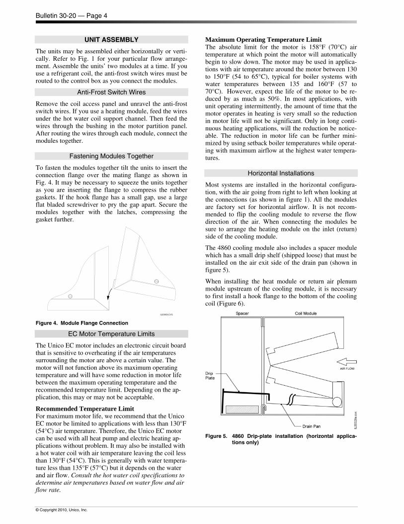
The 4860 cooling module also includes a spacer module which has a small drip shelf (shipped loose) that must be installed on the air exit side of the drain pan (shown in figure 5).
When installing the heat module or return air plenum module upstream of the cooling module, it is necessary to first install a hook flange to the bottom of the cooling coil (Figure 6).
Figure 5. 4860 Drip-plate installation (horizontal applica-
tions only)
Bulletin 30-20 — Page 5
© Copyright 2010, Unico, Inc.
Cooling ModuleReturn AirPlenum
orHeating-Module
Hook Flange(shipped loose with MR or MH unit)
Latch Hook(shipped loose with MR module)
IL00220a.CNV Figure 6. Hook flange location.
Vertical Installations
As shown in figure 1, the modular system can also be configured for vertical up-flow or down-flow. The ar-rangement of modules is different so be sure to follow these instructions.
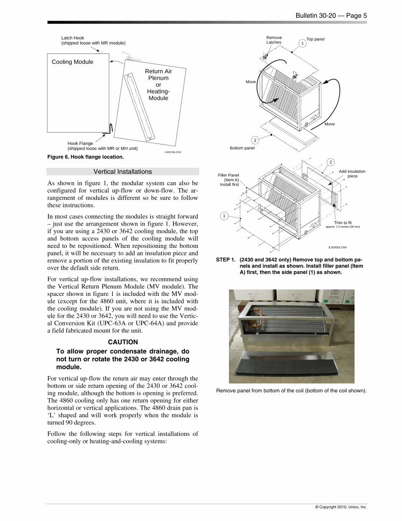
In most cases connecting the modules is straight forward – just use the arrangement shown in figure 1. However, if you are using a 2430 or 3642 cooling module, the top and bottom access panels of the cooling module will need to be repositioned. When repositioning the bottom panel, it will be necessary to add an insulation piece and remove a portion of the existing insulation to fit properly over the default side return.
For vertical up-flow installations, we recommend using the Vertical Return Plenum Module (MV module). The spacer shown in figure 1 is included with the MV mod-ule (except for the 4860 unit, where it is included with the cooling module). If you are not using the MV mod-ule for the 2430 or 3642, you will need to use the Vertic-al Conversion Kit (UPC-63A or UPC-64A) and provide a field fabricated mount for the unit.
CAUTION To allow proper condensate drainage, do not turn or rotate the 2430 or 3642 cooling module.
For vertical up-flow the return air may enter through the bottom or side return opening of the 2430 or 3642 cool-ing module, although the bottom is opening is preferred. The 4860 cooling only has one return opening for either horizontal or vertical applications. The 4860 drain pan is ‘L’ shaped and will work properly when the module is turned 90 degrees.
Follow the following steps for vertical installations of cooling-only or heating-and-cooling systems:
Filler Panel(Item A)
Install first
IL00301b.CNV
Trim to fitapprox. 1.5 inches (38 mm)
2
1
RemoveLatches
Move
Move
1Top panel
2
Bottom panel
Add insulationpiece
STEP 1. (2430 and 3642 only) Remove top and bottom pa-
nels and install as shown. Install filler panel (Item A) first, then the side panel (1) as shown.
Remove panel from bottom of the coil (bottom of the coil shown).
Bulletin 30-20 — Page 6
© Copyright 2010, Unico, Inc.
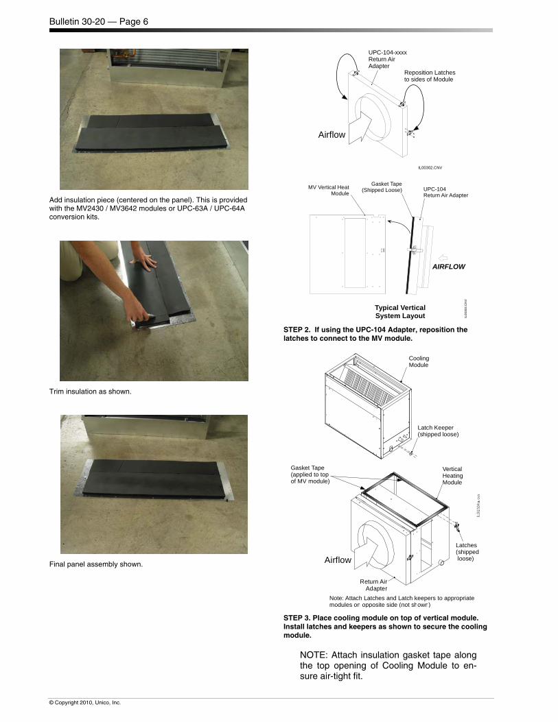
Add insulation piece (centered on the panel). This is provided with the MV2430 / MV3642 modules or UPC-63A / UPC-64A conversion kits.
Trim insulation as shown.
Final panel assembly shown.
IL00302.CNV
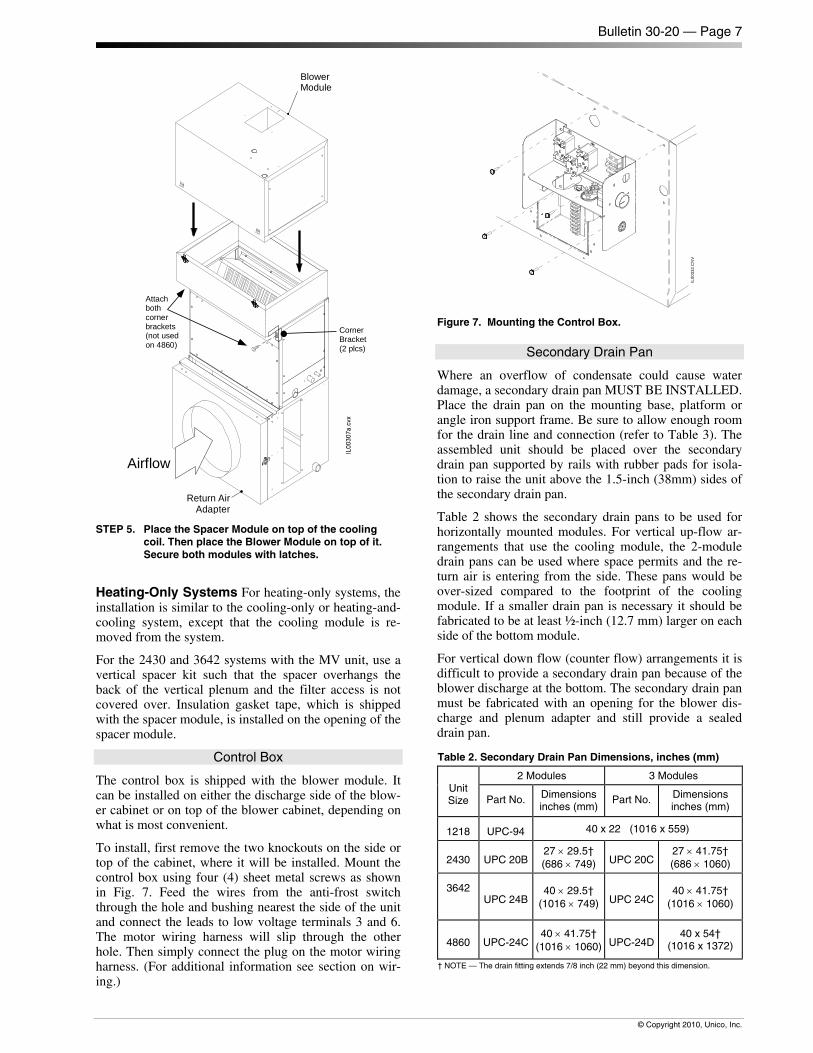
Reposition Latchesto sides of Module
UPC-104-xxxxReturn AirAdapter
Airflow
MV Vertical HeatModule
AIRFLOW
UPC-104Return Air Adapter
Typical VerticalSystem Layout
Gasket Tape(Shipped Loose)
IL00
303.
CN
V
STEP 2. If using the UPC-104 Adapter, reposition the latches to connect to the MV module.
VerticalHeatingModule
Return AirAdapter
Airflow
Latches(shippedloose)
Note: Attach Latches and Latch keepers to appropriatemodules on opposite side (not shown)
Gasket Tape(applied to topof MV module)
CoolingModule
Latch Keeper(shipped loose)
STEP 3. Place cooling module on top of vertical module. Install latches and keepers as shown to secure the cooling module.
NOTE: Attach insulation gasket tape along the top opening of Cooling Module to en-sure air-tight fit.
Bulletin 30-20 — Page 7
© Copyright 2010, Unico, Inc.
BlowerModule
Return AirAdapter
Airflow
CornerBracket(2 plcs)
Attachbothcornerbrackets(not usedon 4860)
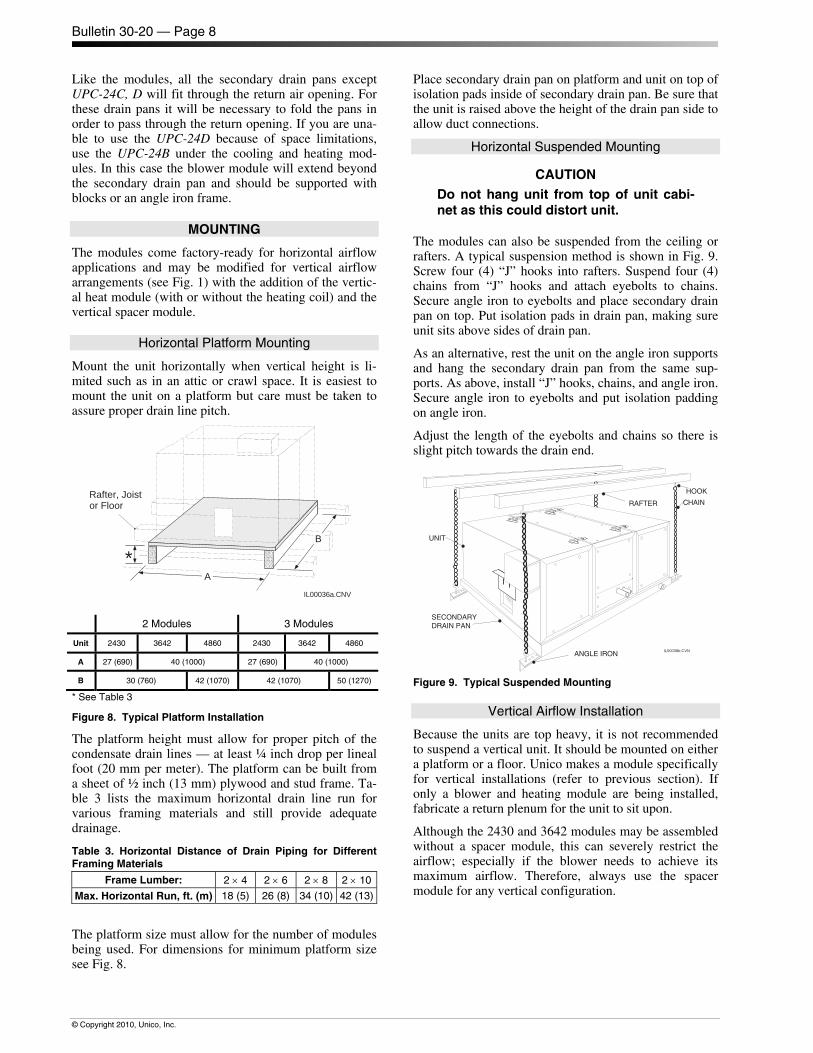
STEP 5. Place the Spacer Module on top of the cooling
coil. Then place the Blower Module on top of it. Secure both modules with latches.
Heating-Only Systems For heating-only systems, the installation is similar to the cooling-only or heating-and-cooling system, except that the cooling module is re-moved from the system.
For the 2430 and 3642 systems with the MV unit, use a vertical spacer kit such that the spacer overhangs the back of the vertical plenum and the filter access is not covered over. Insulation gasket tape, which is shipped with the spacer module, is installed on the opening of the spacer module.
Control Box
The control box is shipped with the blower module. It can be installed on either the discharge side of the blow-er cabinet or on top of the blower cabinet, depending on what is most convenient.
To install, first remove the two knockouts on the side or top of the cabinet, where it will be installed. Mount the control box using four (4) sheet metal screws as shown in Fig. 7. Feed the wires from the anti-frost switch through the hole and bushing nearest the side of the unit and connect the leads to low voltage terminals 3 and 6. The motor wiring harness will slip through the other hole. Then simply connect the plug on the motor wiring harness. (For additional information see section on wir-ing.)
IL00
332.
CN
V
Figure 7. Mounting the Control Box.
Secondary Drain Pan
Where an overflow of condensate could cause water damage, a secondary drain pan MUST BE INSTALLED. Place the drain pan on the mounting base, platform or angle iron support frame. Be sure to allow enough room for the drain line and connection (refer to Table 3). The assembled unit should be placed over the secondary drain pan supported by rails with rubber pads for isola-tion to raise the unit above the 1.5-inch (38mm) sides of the secondary drain pan.
Table 2 shows the secondary drain pans to be used for horizontally mounted modules. For vertical up-flow ar-rangements that use the cooling module, the 2-module drain pans can be used where space permits and the re-turn air is entering from the side. These pans would be over-sized compared to the footprint of the cooling module. If a smaller drain pan is necessary it should be fabricated to be at least ½-inch (12.7 mm) larger on each side of the bottom module.
For vertical down flow (counter flow) arrangements it is difficult to provide a secondary drain pan because of the blower discharge at the bottom. The secondary drain pan must be fabricated with an opening for the blower dis-charge and plenum adapter and still provide a sealed drain pan.
Table 2. Secondary Drain Pan Dimensions, inches (mm)
Unit Size
2 Modules 3 Modules
Part No. Dimensions inches (mm)
Part No. Dimensions inches (mm)
1218 UPC-94 40 x 22 (1016 x 559)
2430 UPC 20B27 × 29.5† (686 × 749) UPC 20C
27 × 41.75† (686 × 1060)
3642
UPC 24B
40 × 29.5† (1016 × 749) UPC 24C
40 × 41.75† (1016 × 1060)
4860 UPC-24C40 × 41.75†
(1016 × 1060) UPC-24D40 x 54†
(1016 x 1372)
† NOTE — The drain fitting extends 7/8 inch (22 mm) beyond this dimension.
Bulletin 30-20 — Page 8
© Copyright 2010, Unico, Inc.
Like the modules, all the secondary drain pans except UPC-24C, D will fit through the return air opening. For these drain pans it will be necessary to fold the pans in order to pass through the return opening. If you are una-ble to use the UPC-24D because of space limitations, use the UPC-24B under the cooling and heating mod-ules. In this case the blower module will extend beyond the secondary drain pan and should be supported with blocks or an angle iron frame.
MOUNTING
The modules come factory-ready for horizontal airflow applications and may be modified for vertical airflow arrangements (see Fig. 1) with the addition of the vertic-al heat module (with or without the heating coil) and the vertical spacer module.
Horizontal Platform Mounting
Mount the unit horizontally when vertical height is li-mited such as in an attic or crawl space. It is easiest to mount the unit on a platform but care must be taken to assure proper drain line pitch.
IL00036a.CNV
A
*
Rafter, Joistor Floor
B
2 Modules 3 Modules
Unit 2430 3642 4860 2430 3642 4860
A 27 (690) 40 (1000) 27 (690) 40 (1000)
B 30 (760) 42 (1070) 42 (1070) 50 (1270)
* See Table 3
Figure 8. Typical Platform Installation
The platform height must allow for proper pitch of the condensate drain lines — at least ¼ inch drop per lineal foot (20 mm per meter). The platform can be built from a sheet of ½ inch (13 mm) plywood and stud frame. Ta-ble 3 lists the maximum horizontal drain line run for various framing materials and still provide adequate drainage.
Table 3. Horizontal Distance of Drain Piping for DifferentFraming Materials
Frame Lumber: 2 × 4 2 × 6 2 × 8 2 × 10
Max. Horizontal Run, ft. (m) 18 (5) 26 (8) 34 (10) 42 (13)
The platform size must allow for the number of modules being used. For dimensions for minimum platform size see Fig. 8.
Place secondary drain pan on platform and unit on top of isolation pads inside of secondary drain pan. Be sure that the unit is raised above the height of the drain pan side to allow duct connections.
Horizontal Suspended Mounting
CAUTION Do not hang unit from top of unit cabi-net as this could distort unit.
The modules can also be suspended from the ceiling or rafters. A typical suspension method is shown in Fig. 9. Screw four (4) “J” hooks into rafters. Suspend four (4) chains from “J” hooks and attach eyebolts to chains. Secure angle iron to eyebolts and place secondary drain pan on top. Put isolation pads in drain pan, making sure unit sits above sides of drain pan.
As an alternative, rest the unit on the angle iron supports and hang the secondary drain pan from the same sup-ports. As above, install “J” hooks, chains, and angle iron. Secure angle iron to eyebolts and put isolation padding on angle iron.
Adjust the length of the eyebolts and chains so there is slight pitch towards the drain end.
IL00038b.CVN
HOOK
RAFTER CHAIN
ANGLE IRON
UNIT
SECONDARYDRAIN PAN
Figure 9. Typical Suspended Mounting
Vertical Airflow Installation
Because the units are top heavy, it is not recommended to suspend a vertical unit. It should be mounted on either a platform or a floor. Unico makes a module specifically for vertical installations (refer to previous section). If only a blower and heating module are being installed, fabricate a return plenum for the unit to sit upon.
Although the 2430 and 3642 modules may be assembled without a spacer module, this can severely restrict the airflow; especially if the blower needs to achieve its maximum airflow. Therefore, always use the spacer module for any vertical configuration.
Bulletin 30-20 — Page 9
© Copyright 2010, Unico, Inc.
DUCT CONNECTIONS
Supply Plenum
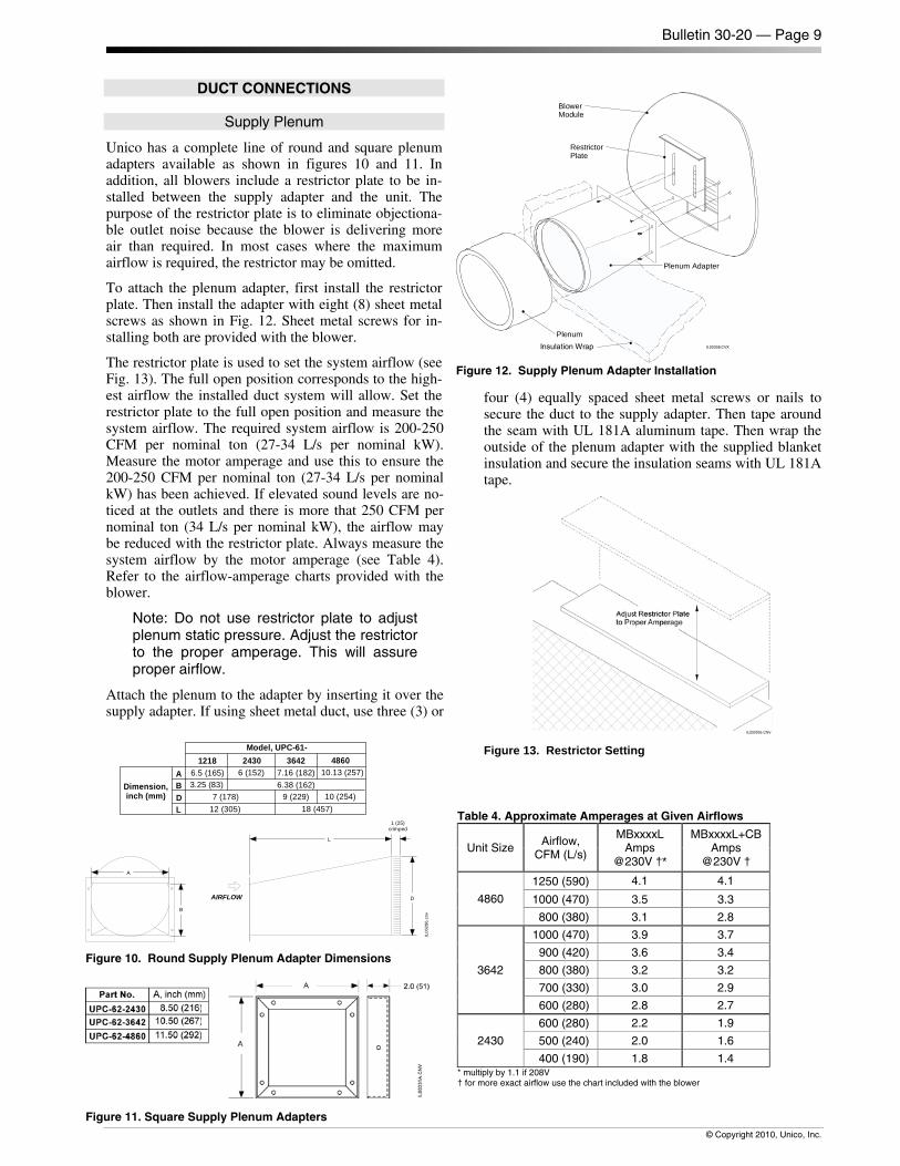
Unico has a complete line of round and square plenum adapters available as shown in figures 10 and 11. In addition, all blowers include a restrictor plate to be in-stalled between the supply adapter and the unit. The purpose of the restrictor plate is to eliminate objectiona-ble outlet noise because the blower is delivering more air than required. In most cases where the maximum airflow is required, the restrictor may be omitted.
To attach the plenum adapter, first install the restrictor plate. Then install the adapter with eight (8) sheet metal screws as shown in Fig. 12. Sheet metal screws for in-stalling both are provided with the blower.
The restrictor plate is used to set the system airflow (see Fig. 13). The full open position corresponds to the high-est airflow the installed duct system will allow. Set the restrictor plate to the full open position and measure the system airflow. The required system airflow is 200-250 CFM per nominal ton (27-34 L/s per nominal kW). Measure the motor amperage and use this to ensure the 200-250 CFM per nominal ton (27-34 L/s per nominal kW) has been achieved. If elevated sound levels are no-ticed at the outlets and there is more that 250 CFM per nominal ton (34 L/s per nominal kW), the airflow may be reduced with the restrictor plate. Always measure the system airflow by the motor amperage (see Table 4). Refer to the airflow-amperage charts provided with the blower.
Note: Do not use restrictor plate to adjust plenum static pressure. Adjust the restrictor to the proper amperage. This will assure proper airflow.
Attach the plenum to the adapter by inserting it over the supply adapter. If using sheet metal duct, use three (3) or
four (4) equally spaced sheet metal screws or nails to secure the duct to the supply adapter. Then tape around the seam with UL 181A aluminum tape. Then wrap the outside of the plenum adapter with the supplied blanket insulation and secure the insulation seams with UL 181A tape.
Figure 13. Restrictor Setting
BlowerModule
RestrictorPlate
Plenum Adapter
PlenumInsulation Wrap IL00308.CVX
Figure 12. Supply Plenum Adapter Installation
Table 4. Approximate Amperages at Given Airflows
Unit Size Airflow,
CFM (L/s)
MBxxxxL Amps
@230V †*
MBxxxxL+CB Amps
@230V †
4860
1250 (590) 4.1 4.1
1000 (470) 3.5 3.3
800 (380) 3.1 2.8
3642
1000 (470) 3.9 3.7
900 (420) 3.6 3.4
800 (380) 3.2 3.2
700 (330) 3.0 2.9
600 (280) 2.8 2.7
2430
600 (280) 2.2 1.9
500 (240) 2.0 1.6
400 (190) 1.8 1.4 * multiply by 1.1 if 208V† for more exact airflow use the chart included with the blower
B
A
D
L
1 (25)crimped
IL00
286.
cnv
AIRFLOW
Model, UPC-61-1218 2430
10 (254)
3642 48607.16 (182) 10.13 (257)
18 (457)9 (229)
ABDimension,
inch (mm)
6.5 (165) 6 (152)3.25 (83) 6.38 (162)
DL
7 (178)12 (305)
Figure 10. Round Supply Plenum Adapter Dimensions
Figure 11. Square Supply Plenum Adapters
Bulletin 30-20 — Page 10
© Copyright 2010, Unico, Inc.
Return Duct
Unico supplies a return duct system but any return duct system is acceptable provided the pressure loss does not exceed 0.15 inches of water (37 Pa), including filters. The return duct should have at least one 90° bend be-tween the unit and filter box to reduce sound transmis-sion directly from the unit.
The Unico Return Duct system has a single return that includes the return air box with filter, the return duct, and the return air adapter (refer to Fig. 3). Multiple re-turns or extra long returns are possible so long as the maximum pressure loss is not exceeded. For vertical installations or tight spaces it may be necessary to fabri-cate a return duct system from duct board or lined metal.
The typical return duct is 10-foot (3 m) in length so it may have to be cut to avoid bunching if the distance to the unit is significantly less than 100-inches. The mini-mum length should be 7-feet (2 m). When given a choice, the shorter distances should be avoided as this may increase sound transmission from the unit.
Cut an opening for the return box as specified in Table 1. For the 2430 and 3642 if the joists or studs are on 16-inch (410mm) centers, there is no need to build a frame to hold the return air box. Otherwise, it will be necessary to construct a frame around the opening. For the 4860 return, it will almost always be necessary to cut and header at least one joist.
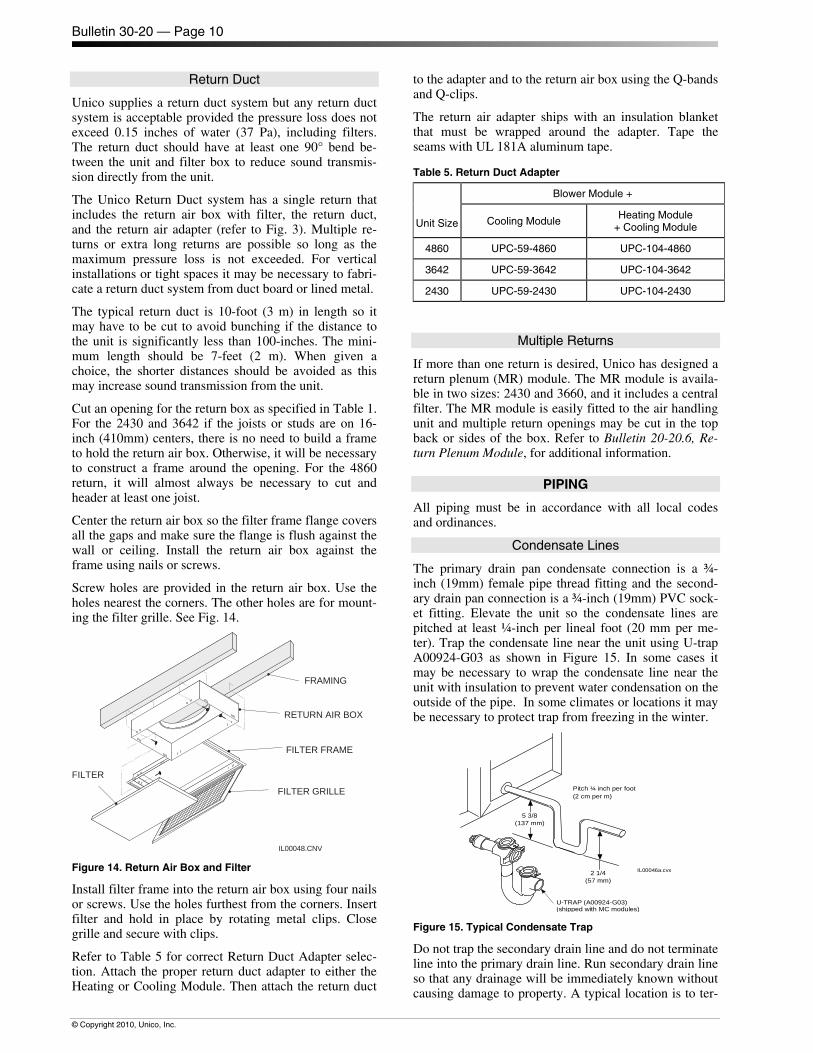
Center the return air box so the filter frame flange covers all the gaps and make sure the flange is flush against the wall or ceiling. Install the return air box against the frame using nails or screws.
Screw holes are provided in the return air box. Use the holes nearest the corners. The other holes are for mount-ing the filter grille. See Fig. 14.
FRAMING
RETURN AIR BOX
FILTER FRAME
FILTER
FILTER GRILLE
IL00048.CNV Figure 14. Return Air Box and Filter
Install filter frame into the return air box using four nails or screws. Use the holes furthest from the corners. Insert filter and hold in place by rotating metal clips. Close grille and secure with clips.
Refer to Table 5 for correct Return Duct Adapter selec-tion. Attach the proper return duct adapter to either the Heating or Cooling Module. Then attach the return duct
to the adapter and to the return air box using the Q-bands and Q-clips.
The return air adapter ships with an insulation blanket that must be wrapped around the adapter. Tape the seams with UL 181A aluminum tape.
Table 5. Return Duct Adapter
Unit Size
Blower Module +
Cooling Module Heating Module
+ Cooling Module
4860 UPC-59-4860 UPC-104-4860
3642 UPC-59-3642 UPC-104-3642
2430 UPC-59-2430 UPC-104-2430
Multiple Returns
If more than one return is desired, Unico has designed a return plenum (MR) module. The MR module is availa-ble in two sizes: 2430 and 3660, and it includes a central filter. The MR module is easily fitted to the air handling unit and multiple return openings may be cut in the top back or sides of the box. Refer to Bulletin 20-20.6, Re-turn Plenum Module, for additional information.
PIPING
All piping must be in accordance with all local codes and ordinances.
Condensate Lines
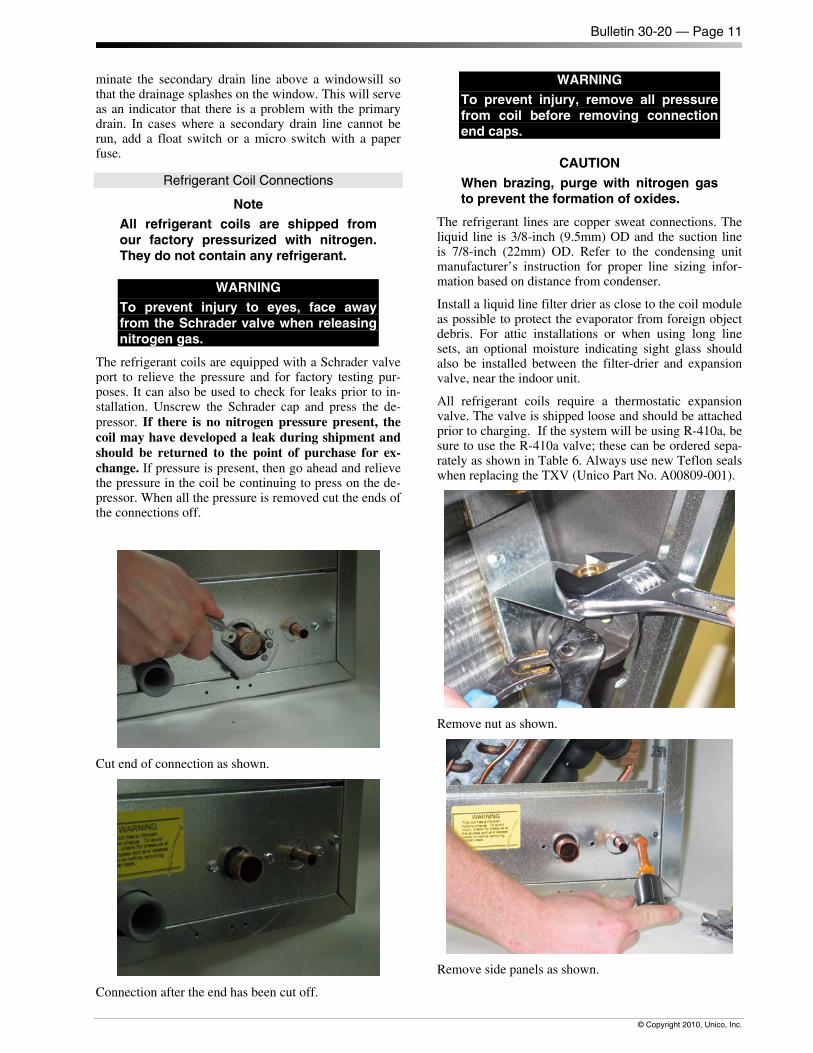
The primary drain pan condensate connection is a ¾-inch (19mm) female pipe thread fitting and the second-ary drain pan connection is a ¾-inch (19mm) PVC sock-et fitting. Elevate the unit so the condensate lines are pitched at least ¼-inch per lineal foot (20 mm per me-ter). Trap the condensate line near the unit using U-trap A00924-G03 as shown in Figure 15. In some cases it may be necessary to wrap the condensate line near the unit with insulation to prevent water condensation on the outside of the pipe. In some climates or locations it may be necessary to protect trap from freezing in the winter.
5 3/8(137 mm)
2 1/4(57 mm)
Pitch ¼ inch per foot(2 cm per m)
IL00046a.cvx
U-TRAP (A00924-G03)(shipped with MC modules)
Figure 15. Typical Condensate Trap
Do not trap the secondary drain line and do not terminate line into the primary drain line. Run secondary drain line so that any drainage will be immediately known without causing damage to property. A typical location is to ter-
Bulletin 30-20 — Page 11
© Copyright 2010, Unico, Inc.
minate the secondary drain line above a windowsill so that the drainage splashes on the window. This will serve as an indicator that there is a problem with the primary drain. In cases where a secondary drain line cannot be run, add a float switch or a micro switch with a paper fuse.
Refrigerant Coil Connections
Note All refrigerant coils are shipped from our factory pressurized with nitrogen. They do not contain any refrigerant.
WARNING To prevent injury to eyes, face away from the Schrader valve when releasing nitrogen gas.
The refrigerant coils are equipped with a Schrader valve port to relieve the pressure and for factory testing pur-poses. It can also be used to check for leaks prior to in-stallation. Unscrew the Schrader cap and press the de-pressor. If there is no nitrogen pressure present, the coil may have developed a leak during shipment and should be returned to the point of purchase for ex-change. If pressure is present, then go ahead and relieve the pressure in the coil be continuing to press on the de-pressor. When all the pressure is removed cut the ends of the connections off.
Cut end of connection as shown.
Connection after the end has been cut off.
WARNING To prevent injury, remove all pressure from coil before removing connection end caps.
CAUTION
When brazing, purge with nitrogen gas to prevent the formation of oxides.
The refrigerant lines are copper sweat connections. The liquid line is 3/8-inch (9.5mm) OD and the suction line is 7/8-inch (22mm) OD. Refer to the condensing unit manufacturer’s instruction for proper line sizing infor-mation based on distance from condenser.
Install a liquid line filter drier as close to the coil module as possible to protect the evaporator from foreign object debris. For attic installations or when using long line sets, an optional moisture indicating sight glass should also be installed between the filter-drier and expansion valve, near the indoor unit.
All refrigerant coils require a thermostatic expansion valve. The valve is shipped loose and should be attached prior to charging. If the system will be using R-410a, be sure to use the R-410a valve; these can be ordered sepa-rately as shown in Table 6. Always use new Teflon seals when replacing the TXV (Unico Part No. A00809-001).
Remove nut as shown.
Remove side panels as shown.
Bulletin 30-20 — Page 12
© Copyright 2010, Unico, Inc.
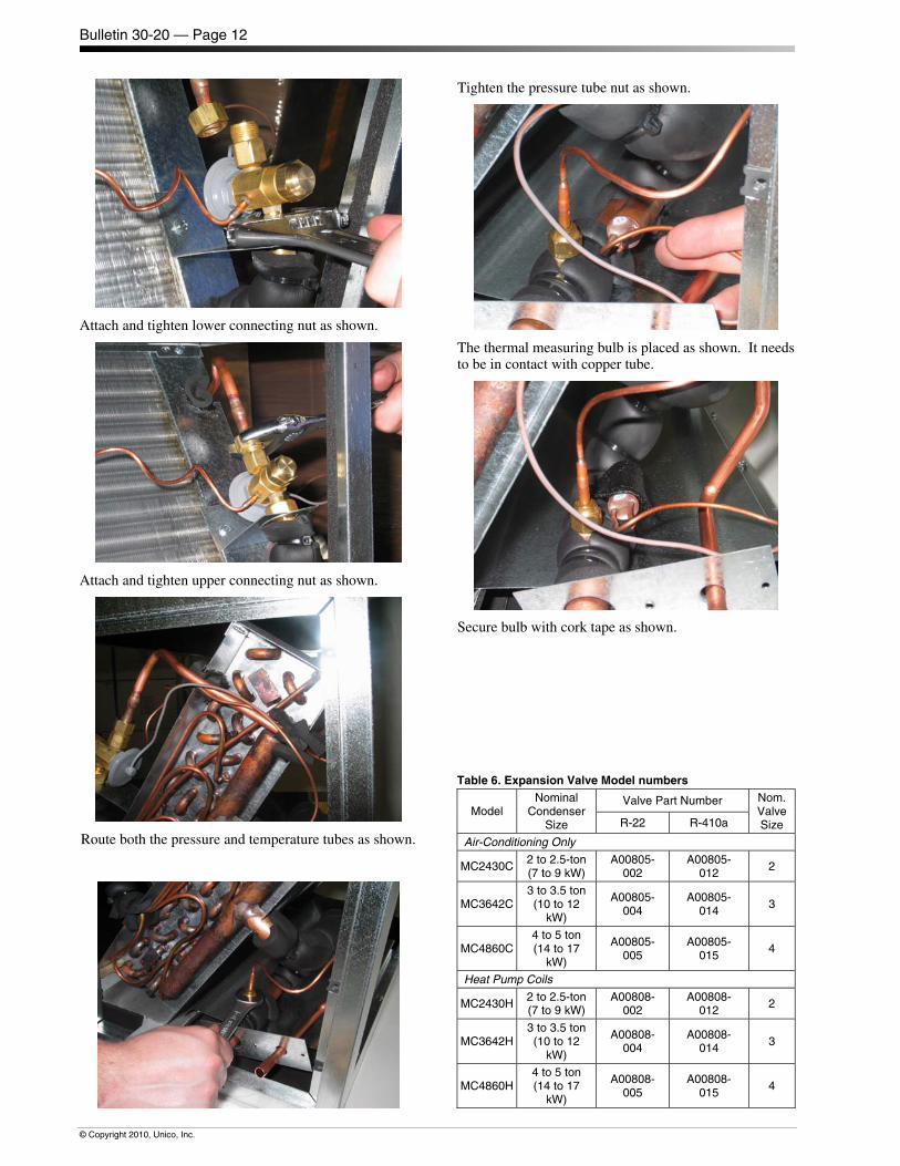
Attach and tighten lower connecting nut as shown.
Attach and tighten upper connecting nut as shown.
Route both the pressure and temperature tubes as shown.
Tighten the pressure tube nut as shown.
The thermal measuring bulb is placed as shown. It needs to be in contact with copper tube.
Secure bulb with cork tape as shown.
Table 6. Expansion Valve Model numbers
Model Nominal
Condenser Size
Valve Part Number Nom. Valve Size R-22 R-410a
Air-Conditioning Only
MC2430C2 to 2.5-ton(7 to 9 kW)
A00805-002
A00805-012
2
MC3642C3 to 3.5 ton(10 to 12
kW)
A00805-004
A00805-014
3
MC4860C4 to 5 ton (14 to 17
kW)
A00805-005
A00805-015
4
Heat Pump Coils
MC2430H2 to 2.5-ton(7 to 9 kW)
A00808-002
A00808-012 2
MC3642H3 to 3.5 ton(10 to 12
kW)
A00808-004
A00808-014 3
MC4860H4 to 5 ton (14 to 17
kW)
A00808-005
A00808-015
4
Bulletin 30-20 — Page 13
© Copyright 2010, Unico, Inc.
Water Connections
If you are installing the hot water coil, remove the side coil access panel and cut away the insulation. Slide the coil into the cabinet and secure with brackets supplied with the hot water coil. Install the access panel after the coil is in place.
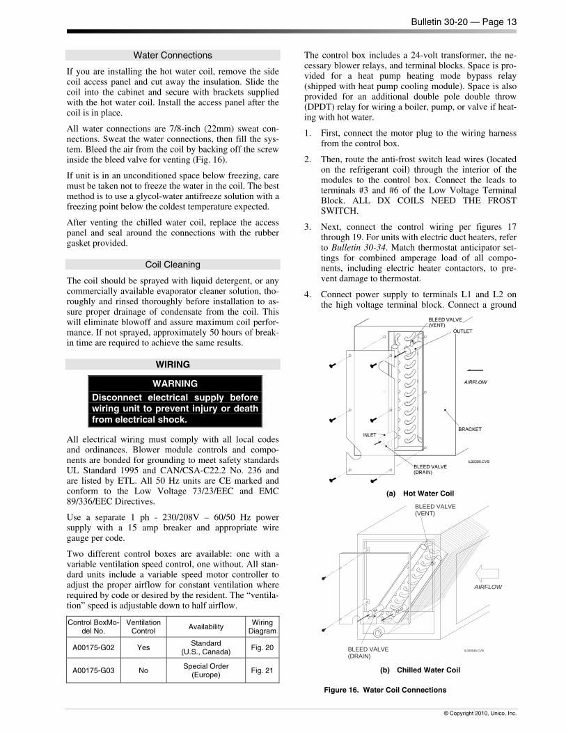
All water connections are 7/8-inch (22mm) sweat con-nections. Sweat the water connections, then fill the sys-tem. Bleed the air from the coil by backing off the screw inside the bleed valve for venting (Fig. 16).
If unit is in an unconditioned space below freezing, care must be taken not to freeze the water in the coil. The best method is to use a glycol-water antifreeze solution with a freezing point below the coldest temperature expected.
After venting the chilled water coil, replace the access panel and seal around the connections with the rubber gasket provided.
Coil Cleaning
The coil should be sprayed with liquid detergent, or any commercially available evaporator cleaner solution, tho-roughly and rinsed thoroughly before installation to as-sure proper drainage of condensate from the coil. This will eliminate blowoff and assure maximum coil perfor-mance. If not sprayed, approximately 50 hours of break-in time are required to achieve the same results.
WIRING
WARNING Disconnect electrical supply before wiring unit to prevent injury or death from electrical shock.
All electrical wiring must comply with all local codes and ordinances. Blower module controls and compo-nents are bonded for grounding to meet safety standards UL Standard 1995 and CAN/CSA-C22.2 No. 236 and are listed by ETL. All 50 Hz units are CE marked and conform to the Low Voltage 73/23/EEC and EMC 89/336/EEC Directives.
Use a separate 1 ph - 230/208V – 60/50 Hz power supply with a 15 amp breaker and appropriate wire gauge per code.
Two different control boxes are available: one with a variable ventilation speed control, one without. All stan-dard units include a variable speed motor controller to adjust the proper airflow for constant ventilation where required by code or desired by the resident. The “ventila-tion” speed is adjustable down to half airflow.
Control BoxMo-del No.
Ventilation Control
Availability Wiring
Diagram
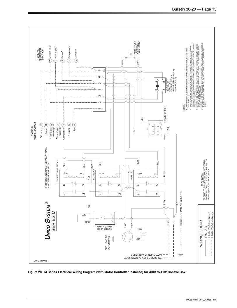
A00175-G02 Yes Standard
(U.S., Canada) Fig. 20
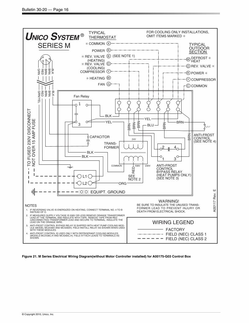
A00175-G03 No Special Order
(Europe) Fig. 21
The control box includes a 24-volt transformer, the ne-cessary blower relays, and terminal blocks. Space is pro-vided for a heat pump heating mode bypass relay (shipped with heat pump cooling module). Space is also provided for an additional double pole double throw (DPDT) relay for wiring a boiler, pump, or valve if heat-ing with hot water.
1. First, connect the motor plug to the wiring harness from the control box.
2. Then, route the anti-frost switch lead wires (located on the refrigerant coil) through the interior of the modules to the control box. Connect the leads to terminals #3 and #6 of the Low Voltage Terminal Block. ALL DX COILS NEED THE FROST SWITCH.
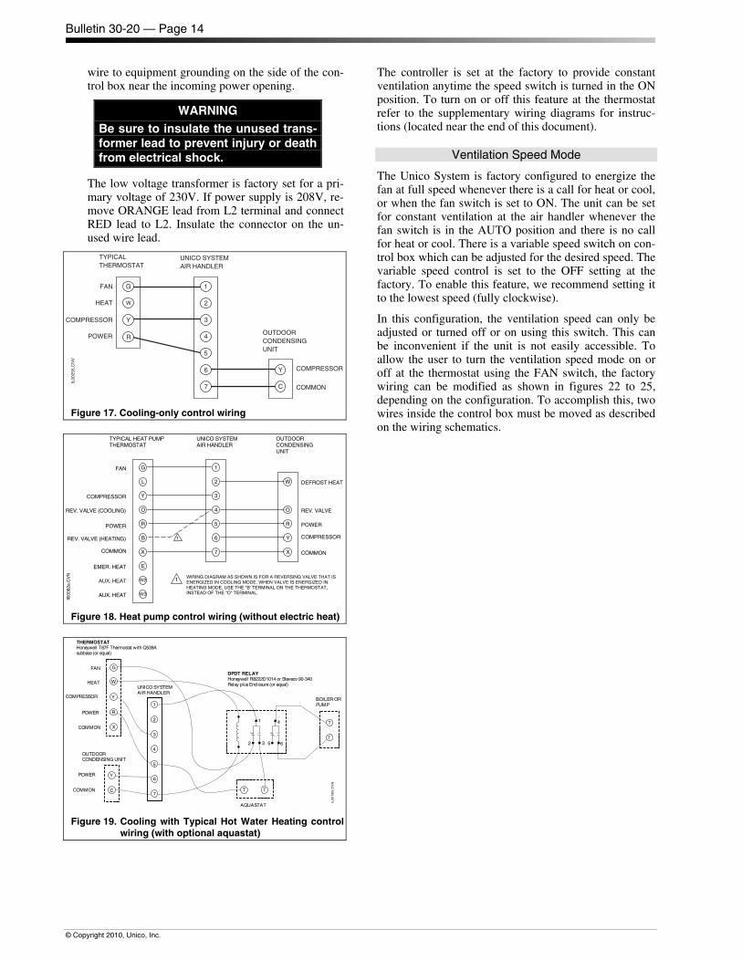
3. Next, connect the control wiring per figures 17 through 19. For units with electric duct heaters, refer to Bulletin 30-34. Match thermostat anticipator set-tings for combined amperage load of all compo-nents, including electric heater contactors, to pre-vent damage to thermostat.
4. Connect power supply to terminals L1 and L2 on the high voltage terminal block. Connect a ground
(a) Hot Water Coil
BLEED VALVE(VENT)
BLEED VALVE(DRAIN)
IL00054b.CVN
IN OUT
AIRFLOW
(b) Chilled Water Coil
Figure 16. Water Coil Connections
Bulletin 30-20 — Page 14
© Copyright 2010, Unico, Inc.
wire to equipment grounding on the side of the con-trol box near the incoming power opening.
WARNING Be sure to insulate the unused trans-former lead to prevent injury or death from electrical shock.
The low voltage transformer is factory set for a pri-mary voltage of 230V. If power supply is 208V, re-move ORANGE lead from L2 terminal and connect RED lead to L2. Insulate the connector on the un-used wire lead.
TYPICALTHERMOSTAT
COMMON
COMPRESSOR
POWER
FAN
UNICO SYSTEMAIR HANDLER
OUTDOORCONDENSINGUNIT
COMPRESSOR
HEAT
IL00
255.
CN
V
2
3
4
5
6
1
7
G
Y
R
W
Y
C
Figure 17. Cooling-only control wiring
W
Y
R
O
X
2
3
4
5
6
7
1
L
G
Y
B
R
O
W3
X
W2
E
TYPICAL HEAT PUMPTHERMOSTAT
POWER
COMMONCOMMON
REV. VALVE (COOLING)
COMPRESSOR
POWER
FAN
UNICO SYSTEMAIR HANDLER
OUTDOORCONDENSINGUNIT
1
EMER. HEAT
REV. VALVE (HEATING)
AUX. HEAT
AUX. HEAT
DEFROST HEAT
REV. VALVE
COMPRESSOR1
WIRING DIAGRAM AS SHOWN IS FOR A REVERSING VALVE THAT ISENERGIZED IN COOLING MODE. WHEN VALVE IS ENERGIZED INHEATING MODE, USE THE "B' TERMINAL ON THE THERMOSTAT,INSTEAD OF THE "O" TERMINAL.
Il000
62a.
CV
N
Figure 18. Heat pump control wiring (without electric heat)
TT
AQUASTAT
Honeywell R8222D1014 or Steveco 90-340Relay plusEnclosure (or equal)
DPDT RELAYG
X
R
Y
W
Y
C
2
3
4
5
6
7
1
T
T
BOILER ORPUMP
Honeywell T87F Thermostat with Q539Asubbase(or equal)
POWER
COMMON
COMMON
HEAT
COMPRESSOR
POWER
FAN
UNICO SYSTEMAIR HANDLER
OUTDOORCONDENSING UNIT
IL00
130c
.CV
N
1 4
32 65
THERMOSTAT
Figure 19. Cooling with Typical Hot Water Heating control wiring (with optional aquastat)
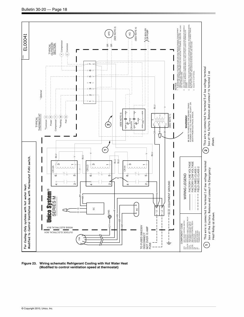
The controller is set at the factory to provide constant ventilation anytime the speed switch is turned in the ON position. To turn on or off this feature at the thermostat refer to the supplementary wiring diagrams for instruc-tions (located near the end of this document).
Ventilation Speed Mode
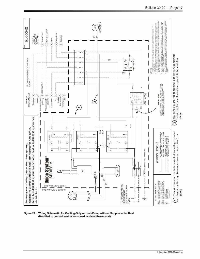
The Unico System is factory configured to energize the fan at full speed whenever there is a call for heat or cool, or when the fan switch is set to ON. The unit can be set for constant ventilation at the air handler whenever the fan switch is in the AUTO position and there is no call for heat or cool. There is a variable speed switch on con-trol box which can be adjusted for the desired speed. The variable speed control is set to the OFF setting at the factory. To enable this feature, we recommend setting it to the lowest speed (fully clockwise).
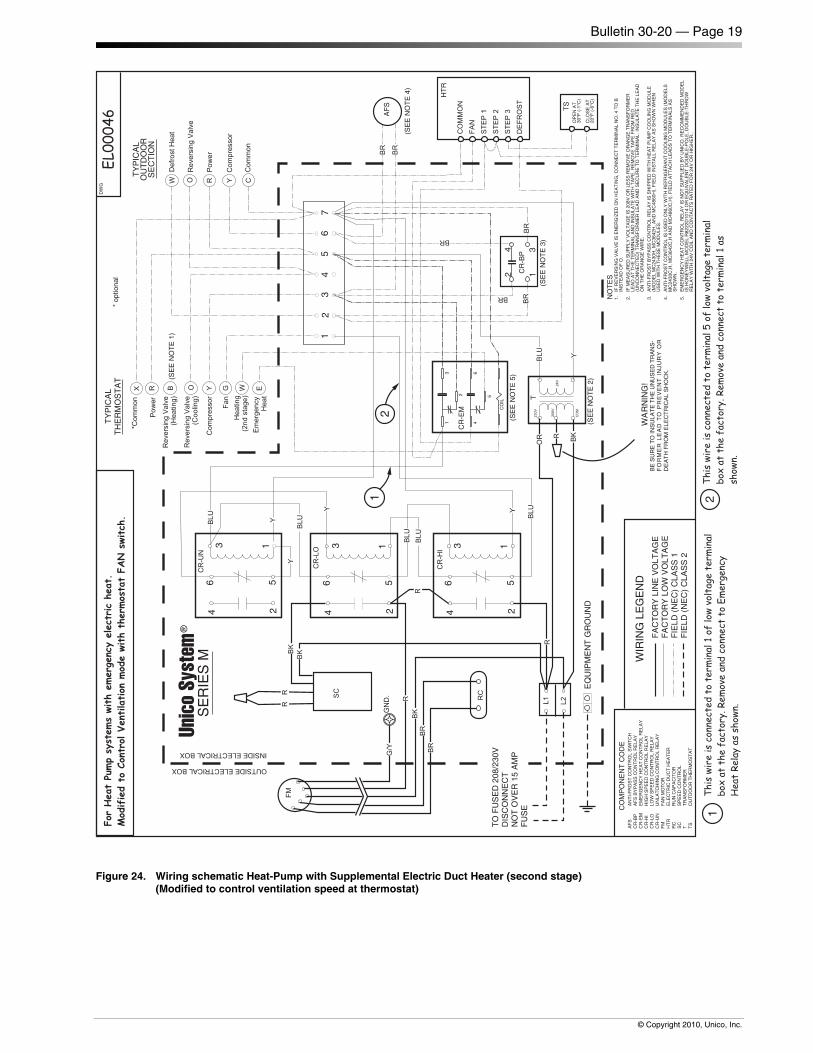
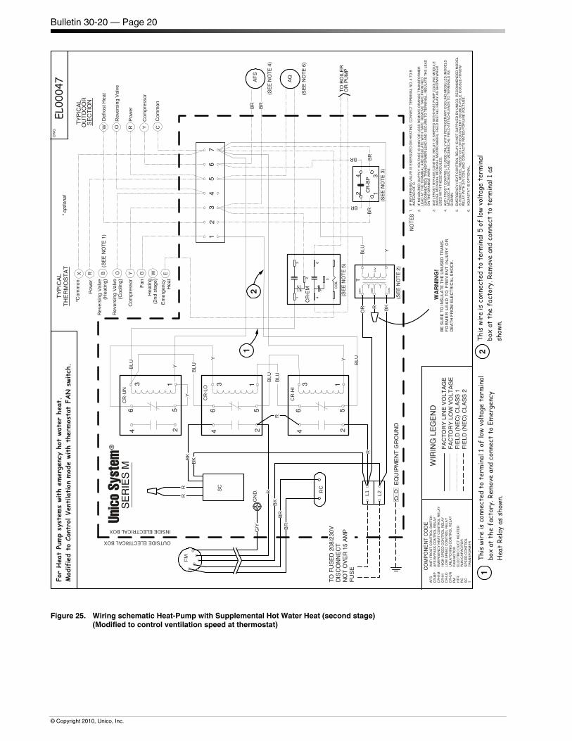
In this configuration, the ventilation speed can only be adjusted or turned off or on using this switch. This can be inconvenient if the unit is not easily accessible. To allow the user to turn the ventilation speed mode on or off at the thermostat using the FAN switch, the factory wiring can be modified as shown in figures 22 to 25, depending on the configuration. To accomplish this, two wires inside the control box must be moved as described on the wiring schematics.
Bulletin 30-20 — Page 15
© Copyright 2010, Unico, Inc.
GR
D. L
EA
D T
OM
OT
OR
BA
SE
TO FUSED 230V DISCONNECTNOT OVER 15 AMP FUSE
TY
PIC
AL
OU
TD
OO
RS
EC
TIO
N
TY
PIC
AL
TH
ER
MO
ST
AT
UN
ICO S
YS
TEM
®
SE
RIE
S M
FO
R C
OO
LIN
G O
NLY
INS
TA
LLA
TIO
NS
,O
MIT
ITE
MS
MA
RK
ED
✳
230V
208V
24V
CO
MM
ON
12
34
56
34
56
71
2
12
34
56
12
34
56
BK
BK
RE
D
BRN
BK
BRNVariable SpeedMotor Controller
YE
L
YE
L
BLU
UN
LAT
CH
ING
RE
LAY
LO R
ELA
Y
YE
L
L1 L2
RE
DB
LU
HI R
ELA
YBLU
BLU
*Com
mon
X
Pow
erR
*Rev
. Val
ve(H
eatin
g)B
*Rev
. Val
ve(C
oolin
g)O
Com
pres
sor
Y
*Hea
ting
W
Fan
GC
omm
onC
Com
pres
sor
Y
Pow
er*
R
Rev
. Val
ve*
O
Def
rost
Hea
t*W
AN
TI-
FR
OS
TC
ON
TR
OL
(SE
E N
OT
E 4
)
BK
YE
L
EQ
UIP
ME
NT
GR
OU
ND
TR
AN
SF
OR
ME
RA
NT
I-F
RO
ST
CO
NT
RO
LB
YP
AS
S R
ELA
Y(H
EA
T P
UM
PS
ON
LY)
(SE
E N
OT
E 3
)
2 1
4 3
BR
N
BR
N
RED
OR
FA
CT
OR
YF
IELD
(N
EC
) C
LAS
S 1
FIE
LD (
NE
C)
CLA
SS
2
WIR
ING
LE
GE
ND
WA
RN
ING
!B
E S
UR
E T
O IN
SU
LAT
E T
HE
UN
US
ED
TR
AN
S-
FO
RM
ER
LE
AD
TO
PR
EV
EN
T I
NJU
RY
OR
DE
AT
H F
RO
M E
LEC
TR
ICA
L S
HO
CK
.
A00816.CNV
NO
TE
S1.
IF R
EV
ER
SIN
G V
ALV
E IS
EN
ER
GIZ
ED
ON
HE
AT
ING
, CO
NN
EC
T T
ER
MIN
AL
NO
. 4 T
O B
INS
TE
AD
OF
O.
2.IF
ME
AS
UR
ED
SU
PP
LY V
OLT
AG
E IS
208
V O
R L
ES
S R
EM
OV
E O
RA
NG
E T
RA
NS
FO
RM
ER
LEA
D A
T T
HE
TE
RM
INA
L A
ND
INS
ULA
TE
WIT
H T
AP
E. R
EM
OV
E T
AP
E F
RO
M R
ED
(UN
CO
NN
EC
TE
D)
TR
AN
SF
OR
ME
R L
EA
D A
ND
SE
CU
RE
TO
TE
RM
INA
L. IN
SU
LAT
E T
HE
LE
AD
ON
TH
E O
RA
NG
E W
IRE
.
3.A
NT
I-F
RO
ST
CO
NT
RO
L B
YP
AS
S R
ELA
Y IS
SH
IPP
ED
WIT
H H
EA
T P
UM
P C
OO
LIN
G M
OD
ULE
(MO
DE
L M
C24
30H
, MC
3642
H, A
ND
MC
4860
H).
FIE
LD IN
ST
ALL
RE
LAY
AS
SH
OW
N W
HE
NU
SE
D W
ITH
TH
ES
E M
OD
ULE
S.
4.A
NT
I-F
RO
ST
CO
NT
RO
L IS
US
ED
ON
LY W
ITH
RE
FR
IGE
RA
NT
CO
OLI
NG
MO
DU
LES
(M
OD
ELS
MC
2430
C,H
, MC
3642
C,H
AN
D M
C48
60C
,H).
FIE
LD A
TT
AC
H L
EA
DS
TO
TE
RM
INA
LS A
SS
HO
WN
.
YE
L
BLU
RED
RED
BLU
Figure 20. M Series Electrical Wiring Diagram (with Motor Controller installed) for A00175-G02 Control Box
Bulletin 30-20 — Page 16
© Copyright 2010, Unico, Inc.
B
R
X
FACTORYFIELD (NEC) CLASS 1FIELD (NEC) CLASS 2
WIRING LEGEND
208V 230V
24V
COMMON
Fan Relay
SEENOTE 2
L1
L2
BLK
RE
DB
RN
BR
N
GR
N
TO
FU
SE
D 2
30V
DIS
CO
NN
EC
TN
OT
OV
ER
15
AM
P F
US
E
EQUIPT. GROUND
1 2 3 4 5 6 7
TRANS-FORMER
ANTI-FROSTCONTROLBYPASS RELAY(HEAT PUMPS ONLY)(SEE NOTE 3)
ANTI-FROSTCONTROL(SEE NOTE 4)
COMMON
COMPRESSOR
POWER ✳
REV. VALVE ✳
DEFROST ✳HEAT
TYPICALOUTDOORSECTION
(SEE NOTE 1)
TYPICALTHERMOSTAT
FAN
✳ HEATING
COMPRESSOR
✳ REV. VALVE(COOLING)
✳ REV. VALVE(HEATING)
POWER
✳ COMMON
NOTES1. IF REVERSING VALVE IS ENERGIZED ON HEATING, CONNECT TERMINAL NO. 4 TO B
INSTEAD OF O.
2. IF MEASURED SUPPLY VOLTAGE IS 208V OR LESS REMOVE ORANGE TRANSFORMERLEAD AT THE TERMINAL AND INSULATE WITH TAPE. REMOVE TAPE FROM RED(UNCONNECTED) TRANSFORMER LEAD AND SECURE TO TERMINAL. INSULATE THELEAD ON THE ORANGE WIRE.
3. ANTI-FROST CONTROL BYPASS RELAY IS SHIPPED WITH HEAT PUMP COOLING MOD-ULE (MODEL MC2436H AND MC4260H). FIELD INSTALL RELAY AS SHOWN WHEN USEDWITH THESE MODULES.
4. ANTI-FROST CONTROL IS USED ONLY WITH REFRIGERANT COOLING MODULES(MODELS MC2436C,H AND MC4260C,H). FIELD ATTACH LEADS TO TERMINALS ASSHOWN.
UNICO SYSTEM ®SERIES M
FOR COOLING ONLY INSTALLATIONS,OMIT ITEMS MARKED ✳
WARNING!
A00
117
Rev
. E
BE SURE TO INSULATE THE UNUSED TRANS-FORMER LEAD TO PREVENT INJURY ORDEATH FROM ELECTRICAL SHOCK.
G
W
Y
O
C
Y
R
O
W
2
1
4
3
YELBRN
BR
N
YEL
BR
N
BR
N
BR
N
BLK
BLK
BLU
BR
N
BR
N B
LK
3
1
CAPACITOR
BLK
GR
N/Y
EL
RE
D
RE
D
ORG
BR
N
Figure 21. M Series Electrical Wiring Diagram(without Motor Controller installed) for A00175-G03 Control Box
Bulletin 30-20 — Page 17
© Copyright 2010, Unico, Inc.
TY
PIC
AL
OU
TD
OO
RS
EC
TIO
N
TY
PIC
AL
TH
ER
MO
ST
AT
230V
208V
24V
CO
M
T
12
34
56
34
56
71
2
12
34
56
12
34
56
CR
-UN
CR
-LO
L1 L2
CR
-HI
BLU
*Com
mon
X
Pow
erR
*Rev
ersi
ngVa
lve
(Hea
ting)
B
*Rev
ersi
ngVa
lve
(Coo
ling)
O
Com
pres
sor
Y
Hea
ting
(2nd
stag
e)W
Fan
G
Com
mon
C
Com
pres
sor
Y
Pow
erR
Rev
ersi
ngV
alve
*O
Def
rost
Hea
t*W
(SE
EN
OT
E4)
EQ
UIP
ME
NT
GR
OU
ND
(SE
EN
OT
E3)
2 1
4 3
WA
RN
ING
!B
ES
UR
ET
OIN
SU
LA
TE
TH
EU
NU
SE
DT
RA
NS
-F
OR
ME
RL
EA
DT
OP
RE
VE
NT
INJ
UR
YO
RD
EA
TH
FR
OM
EL
EC
TR
ICA
LS
HO
CK
.
NO
TE
S1
.IF
RE
VE
RS
ING
VA
LVE
ISE
NE
RG
IZE
DO
NH
EA
TIN
G,C
ON
NE
CT
TE
RM
INA
LN
O.
4T
OB
INS
TE
AD
OF
O.
2.
IFM
EA
SU
RE
DS
UP
PLY
VO
LTA
GE
IS2
08V
OR
LES
SR
EM
OV
EO
RA
NG
ET
RA
NS
FO
RM
ER
LEA
DA
TT
HE
TE
RM
INA
LA
ND
INS
UL
AT
EW
ITH
TA
PE
.RE
MO
VE
TA
PE
FR
OM
RE
D(U
NC
ON
NE
CT
ED
)T
RA
NS
FO
RM
ER
LE
AD
AN
DS
EC
UR
ET
OT
ER
MIN
AL
.IN
SU
LA
TE
TH
ELE
AD
ON
TH
EO
RA
NG
EW
IRE
.
3.
AN
TI-
FR
OS
TB
YP
AS
SC
ON
TR
OL
RE
LA
YIS
SH
IPP
ED
WIT
HH
EA
TP
UM
PC
OO
LIN
GM
OD
ULE
(MO
DE
LM
C2
430H
,MC
3642
H,A
ND
MC
486
0H).
FIE
LDIN
ST
ALL
RE
LAY
AS
SH
OW
NW
HE
NU
SE
DW
ITH
TH
ES
EM
OD
ULE
S.
4.
AN
TI-
FR
OS
TC
ON
TR
OL
ISU
SE
DO
NLY
WIT
HR
EF
RIG
ER
AN
TC
OO
LIN
GM
OD
ULE
S(M
OD
EL
SM
C24
30C
,H,
MC
3642
C,H
AN
DM
C4
860C
,H).
FIE
LDA
TT
AC
HLE
AD
ST
OT
ER
MIN
ALS
AS
SH
OW
N.
BLU
ForRe
friger
antCo
oling-
Onlyor
Hea
tPu
mpsy
stem
s.Mod
ified
toCo
ntro
lVe
ntila
tion
mod
ewith
ther
mos
tatFA
Nsw
itch
.Re
ferto
EL00
041
ifsy
stem
hasho
twa
terhe
ator
EL00
046
ifsy
stem
has
elec
tric
heat
.
EL00
040
BK
R
BRB
R
RC
FM
GN
D.
G/Y
CO
MP
ON
EN
TC
OD
E
AF
SA
NT
I-F
RO
ST
CO
NT
RO
LS
WIT
CH
CR
-BP
AF
SB
YP
AS
SC
ON
TR
OL
RE
LAY
CR
-HI
HIG
HS
PE
ED
CO
NT
RO
LR
ELA
YC
R-L
OLO
WS
PE
ED
CO
NT
RO
LR
EL
AY
CR
-UN
UN
LA
TC
HIN
GC
ON
TR
OL
RE
LA
YF
MF
AN
MO
TO
RR
CR
UN
CA
PA
CIT
OR
SC
SP
EE
DC
ON
TR
OL
TT
RA
NS
FO
RM
ER
FA
CT
OR
YLI
NE
VO
LTA
GE
FA
CT
OR
YLO
WV
OLT
AG
EF
IELD
(NE
C)
CLA
SS
1F
IELD
(NE
C)
CLA
SS
2
WIR
ING
LEG
EN
D
R
BKR
RBK
R SC
R
BK
BR
CR
-BP
*Em
erge
ncy
Hea
tE
AF
S
BLU
BLU
Y
BLU
BLU
BR
BR
BR
BR
BR
DW
G
OUTSIDEELECTRICALBOX
INSIDEELECTRICALBOX
TO
FU
SE
D20
8/23
0VD
ISC
ON
NE
CT
NO
TO
VE
R15
AM
PF
US
E
Y
Y
Y
OR
2
12
This
wireis
conn
ecte
dto
term
inal
1of
lowvo
ltag
ete
rminal
boxat
thefa
ctor
y.Re
mov
ean
dco
nnec
tto
term
inal
3as
show
n.
This
wire
isco
nnec
tedto
term
inal
5of
low
voltag
ete
rminal
boxat
thefa
ctor
y.Re
mov
ean
dco
nnec
tto
term
inal
1as
show
n.
(SE
EN
OT
E1)
(SE
EN
OT
E2)
Y
1
For
cool
ing-
only
syst
ems,
omit
item
sm
arke
d*.
Unic
oSy
stem
®
SE
RIE
SM
Figure 22. Wiring Schematic for Cooling-Only or Heat-Pump without Supplemental Heat (Modified to control ventilation speed mode at thermostat)
Bulletin 30-20 — Page 18
© Copyright 2010, Unico, Inc.
TY
PIC
AL
OU
TD
OO
RS
EC
TIO
N
TY
PIC
AL
TH
ER
MO
ST
AT
*O
ptio
nal
230V
208V
24V
CO
M
T
12
34
56
34
56
71
2
12
34
56
12
34
56
CR
-UN
CR
-LO
L1 L2
CR
-HI
BLU
*Com
mon
X
Pow
erR
Com
pres
sor
Y
*Hea
ting
W
Fan
GC
omm
onC
Com
pres
sor
Y
(SE
EN
OT
E2)
EQ
UIP
ME
NT
GR
OU
ND
WA
RN
ING
!B
ES
UR
ET
OIN
SU
LA
TE
TH
EU
NU
SE
DT
RA
NS
-F
OR
ME
RL
EA
DT
OP
RE
VE
NT
INJ
UR
YO
RD
EA
TH
FR
OM
EL
EC
TR
ICA
LS
HO
CK
.
NO
TE
S1
.IF
ME
AS
UR
ED
SU
PP
LYV
OLT
AG
EIS
208
VO
RLE
SS
RE
MO
VE
OR
AN
GE
TR
AN
SF
OR
ME
RLE
AD
AT
TH
ET
ER
MIN
AL
AN
DIN
SU
LA
TE
WIT
HT
AP
E.R
EM
OV
ET
AP
EF
RO
MR
ED
(UN
CO
NN
EC
TE
D)
TR
AN
SF
OR
ME
RLE
AD
AN
DS
EC
UR
ET
OT
ER
MIN
AL.
INS
UL
AT
ET
HE
LEA
DO
NT
HE
OR
AN
GE
WIR
E.
2.
AN
TI-
FR
OS
TC
ON
TR
OL
ISU
SE
DO
NLY
WIT
HR
EF
RIG
ER
AN
TC
OO
LIN
GM
OD
ULE
S(M
OD
ELS
MC
2430
C,H
,M
C36
42C
,HA
ND
MC
486
0C,H
).F
IELD
AT
TA
CH
L EA
DS
TO
TE
RM
INA
LSA
SS
HO
WN
.
3.
EM
ER
GE
NC
YH
EA
TC
ON
TR
OL
RE
LA
YIS
NO
TS
UP
PL
IED
BY
UN
ICO
.R
EC
OM
ME
ND
ED
MO
DE
LIS
HO
NE
YW
EL
LM
OD
EL
R82
22D
101
4O
RE
QU
IVA
LE
NT
DO
UB
LE-P
OL
E,D
OU
BLE
-TH
RO
WR
ELA
YW
ITH
24V
CO
ILA
ND
CO
NT
AC
TS
RA
TE
DF
OR
LIN
EV
OL
TA
GE
.
4A
QU
AS
TA
TIS
OP
TIO
NA
L.
BLU
ForCo
oling-
Onlysy
stem
swith
hotwa
terhe
at.
Mod
ified
toCo
ntro
lVe
ntila
tion
mod
ewith
ther
mos
tatFA
Nsw
itch
.EL
0004
1
BK
R
BRB
R
RC
FM
GN
D.
G/Y
CO
MP
ON
EN
TC
OD
EA
FS
AN
TI-
FR
OS
TC
ON
TR
OL
SW
ITC
HA
QA
QU
A-S
TA
TC
R-H
TR
EM
ER
GE
NC
YH
EA
TC
ON
TR
OL
RE
LA
YC
R-H
IH
IGH
SP
EE
DC
ON
TR
OL
RE
LAY
CR
-LO
LOW
SP
EE
DC
ON
TR
OL
RE
LAY
CR
-UN
UN
LAT
CH
ING
CO
NT
RO
LR
EL
AY
FM
FA
NM
OT
OR
RC
RU
NC
AP
AC
ITO
RS
CS
PE
ED
CO
NT
RO
LT
TR
AN
SF
OR
ME
R
FA
CT
OR
YLI
NE
VO
LTA
GE
FA
CT
OR
YLO
WV
OLT
AG
EF
IELD
(NE
C)
CLA
SS
1F
IELD
(NE
C)
CLA
SS
2
WIR
ING
LEG
EN
D
R
BKR
RBK
R SC
R
BK
BR
1
CR
-HT
R CO
IL
3
2
46
5
BLU
BLU
Y
BLU
BLU
BR
DW
G
OUTSIDEELECTRICALBOX
INSIDEELECTRICALBOX
TO
FU
SE
D20
8/23
0VD
ISC
ON
NE
CT
NO
TO
VE
R15
AM
PF
US
E
Y
Y
Y
OR
12
12
This
wireis
conn
ecte
dto
term
inal
1of
lowvo
ltag
ete
rminal
boxat
thefa
ctor
y.Re
mov
ean
dco
nnec
tto
Emer
genc
yHea
tRe
layas
show
n.
This
wire
isco
nnec
tedto
term
inal
5of
low
voltag
ete
rminal
boxat
thefa
ctor
y.Re
mov
ean
dco
nnec
tto
term
inal
1as
show
n.
(SE
EN
OT
E3)
(SE
EN
OT
E1)
Y
(SE
EN
OT
E4)
AQ
TO
BO
ILE
RO
RP
UM
P
AF
S
Unic
oSy
stem
®
SE
RIE
SM
Figure 23. Wiring schematic Refrigerant Cooling with Hot Water Heat (Modified to control ventilation speed at thermostat)
Bulletin 30-20 — Page 19
© Copyright 2010, Unico, Inc.
TY
PIC
AL
OU
TD
OO
R
SE
CT
ION
TY
PIC
AL
TH
ER
MO
ST
AT
Unic
o Sy
stem
SE
RIE
S M
* op
tiona
l
����
����
���
�
T
12
34
56
34
56
71
2
12
34
56
12
34
56
��� �
����
��
��
�����
��
�������
�
�����
�
�������� !�"#��!
$��"%�� &
�
�������� !�"#��!
$���#�� &
���'������
(
��"%�� !
$��)!�%" �&*
+"�
,
������
�
���'������
(
�����
�
�������� !�"#��
-�.���%!��"%
*
(SE
E N
OT
E 4
)
EQ
UIP
ME
NT
GR
OU
ND
(SE
E N
OT
E 3
)
2 1
4 3
WA
RN
ING
!B
E S
UR
E T
O IN
SU
LAT
E T
HE
UN
US
ED
TR
AN
S-
FO
RM
ER
LE
AD
TO
PR
EV
EN
T I
NJU
RY
OR
D
EA
TH
FR
OM
ELE
CT
RIC
AL
SH
OC
K.
NO
TE
S1.
IF R
EV
ER
SIN
G V
ALV
E IS
EN
ER
GIZ
ED
ON
HE
AT
ING
, CO
NN
EC
T T
ER
MIN
AL
NO
. 4 T
O B
IN
ST
EA
D O
F O
.
2.IF
ME
AS
UR
ED
SU
PP
LY V
OLT
AG
E IS
208
V O
R L
ES
S R
EM
OV
E O
RA
NG
E T
RA
NS
FO
RM
ER
LE
AD
AT
TH
E T
ER
MIN
AL
AN
D IN
SU
LAT
E W
ITH
TA
PE
. RE
MO
VE
TA
PE
FR
OM
RE
D
(UN
CO
NN
EC
TE
D)
TR
AN
SF
OR
ME
R L
EA
D A
ND
SE
CU
RE
TO
TE
RM
INA
L. IN
SU
LAT
E T
HE
LE
AD
O
N T
HE
OR
AN
GE
WIR
E.
3.A
NT
I-F
RO
ST
BY
PA
SS
CO
NT
RO
L R
ELA
Y IS
SH
IPP
ED
WIT
H H
EA
T P
UM
P C
OO
LIN
G M
OD
ULE
(M
OD
EL
MC
2430
H, M
C36
42H
, AN
D M
C48
60H
). F
IELD
INS
TA
LL R
ELA
Y A
S S
HO
WN
WH
EN
U
SE
D W
ITH
TH
ES
E M
OD
ULE
S.
4.A
NT
I-F
RO
ST
CO
NT
RO
L IS
US
ED
ON
LY W
ITH
RE
FR
IGE
RA
NT
CO
OLI
NG
MO
DU
LES
(M
OD
ELS
M
C24
30C
,H, M
C36
42C
,H A
ND
MC
4860
C,H
). F
IELD
AT
TA
CH
LE
AD
S T
O T
ER
MIN
ALS
AS
S
HO
WN
.
5.E
ME
RG
EN
CY
HE
AT
CO
NT
RO
L R
ELA
Y IS
NO
T S
UP
PLI
ED
BY
UN
ICO
. RE
CO
MM
EN
DE
D M
OD
EL
IS H
ON
EY
WE
LL M
OD
EL
R82
22D
1014
OR
EQ
UIV
ALE
NT
DO
UB
LE-P
OLE
, DO
UB
LE-T
HR
OW
R
ELA
Y W
ITH
24V
CO
IL A
ND
CO
NT
AC
TS
RA
TE
D F
OR
24V
OR
HIG
HE
R..
��
���
�����
�� �
���
����
�����
����
���
���
���
����
����
�
���
������
�����
�����
��
������
����
���
���
����
���
������
����
��������
�/
�
��
��
��
+
,�-0
,1(
CO
MP
ON
EN
T C
OD
EA
FS
AN
TI-
FR
OS
T C
ON
TR
OL
SW
ITC
H
CR
-BP
AF
S B
YP
AS
S C
ON
TR
OL
RE
LAY
C
R-E
ME
ME
RG
EN
CY
HE
AT
CO
NT
RO
L R
ELA
Y
CR
-HI
HIG
H S
PE
ED
CO
NT
RO
L R
ELA
Y
CR
-LO
LOW
SP
EE
D C
ON
TR
OL
RE
LAY
C
R-U
NU
NLA
TC
HIN
G C
ON
TR
OL
RE
LAY
F
MF
AN
MO
TO
R
HT
RE
LEC
TR
IC D
UC
T H
EA
TE
R
RC
RU
N C
AP
AC
ITO
R
SC
SP
EE
D C
ON
TR
OL
TT
RA
NS
FO
RM
ER
T
SO
UT
DO
OR
TH
ER
MO
ST
AT
FA
CT
OR
Y L
INE
VO
LTA
GE
F
AC
TO
RY
LO
W V
OLT
AG
E
FIE
LD (
NE
C)
CLA
SS
1
FIE
LD (
NE
C)
CLA
SS
2
WIR
ING
LE
GE
ND
�
�/�
��/
� 2�
�
�/
��
CR
-BP
3��� ��45!
��"%3
AF
S
1
CR
-EM C
OIL
3
2
46
5
��
��
(
��
��
��
+6�
273�!�
273�!�
273�!�
-3+�27
HT
R
��
����
��
��
DW
G
72�-3!3�3�7���6�!��!!��2�-3!3�3�7���6�!��
TO
FU
SE
D 2
08/2
30V
D
ISC
ON
NE
CT
N
OT
OV
ER
15
AM
P
FU
SE
(
(
(
�
12
12
���� ������������������ ������������������������ �����
���������������� ���������������������������� ������
�����������������
���� ������������������ �����!������������������ �����
���������������� ��������������������������� ���������
�����
(SE
E N
OT
E 5
)(SE
E N
OT
E 1
)
(SE
E N
OT
E 2
)
(T
SO
PE
N A
T
30F
(-1
C)
CLO
SE
AT
20
F (
-6C
)
Figure 24. Wiring schematic Heat-Pump with Supplemental Electric Duct Heater (second stage) (Modified to control ventilation speed at thermostat)
Bulletin 30-20 — Page 20
© Copyright 2010, Unico, Inc.
TY
PIC
AL
OU
TD
OO
RS
EC
TIO
N
TY
PIC
AL
TH
ER
MO
ST
AT
*op
tiona
l
230V
208V
24V
CO
M
T
12
34
56
34
56
71
2
12
34
56
12
34
56
CR
-UN
CR
-LO
L1 L2
CR
-HI
BLU
*Com
mon
X
Pow
erR
Rev
ersi
ngVa
lve
(Hea
ting)
B
Rev
ersi
ngVa
lve
(Coo
ling)
O
Com
pres
sor
Y
Hea
ting
(2nd
stag
e)W
Fan
G
Com
mon
C
Com
pres
sor
Y
Pow
erR
Rev
ersi
ngV
alve
O
Def
rost
Hea
tW
(SE
EN
OT
E4)
EQ
UIP
ME
NT
GR
OU
ND
(SE
EN
OT
E3)
2 1
4 3
WA
RN
ING
!B
ES
UR
ET
OIN
SU
LA
TE
TH
EU
NU
SE
DT
RA
NS
-F
OR
ME
RL
EA
DT
OP
RE
VE
NT
INJ
UR
YO
RD
EA
TH
FR
OM
EL
EC
TR
ICA
LS
HO
CK
.
NO
TE
S1.
IFR
EV
ER
SIN
GV
ALV
EIS
EN
ER
GIZ
ED
ON
HE
AT
ING
,C
ON
NE
CT
TE
RM
INA
LN
O.4
TO
BIN
ST
EA
DO
FO
.
2.IF
ME
AS
UR
ED
SU
PP
LY
VO
LT
AG
EIS
208V
OR
LE
SS
RE
MO
VE
OR
AN
GE
TR
AN
SF
OR
ME
RL
EA
DA
TT
HE
TE
RM
INA
LA
ND
INS
UL
AT
EW
ITH
TA
PE
.R
EM
OV
ET
AP
EF
RO
MR
ED
(UN
CO
NN
EC
TE
D)
TR
AN
SF
OR
ME
RLE
AD
AN
DS
EC
UR
ET
OT
ER
MIN
AL.
INS
ULA
TE
TH
EL
EA
DO
NT
HE
OR
AN
GE
WIR
E.
3.A
NT
I-F
RO
ST
BY
PA
SS
CO
NT
RO
LR
ELA
YIS
SH
IPP
ED
WIT
HH
EA
TP
UM
PC
OO
LIN
GM
OD
UL
E(M
OD
EL
MC
2430
H,M
C36
42H
,A
ND
MC
4860
H).
FIE
LDIN
ST
ALL
RE
LA
YA
SS
HO
WN
WH
EN
US
ED
WIT
HT
HE
SE
MO
DU
LES
.
4.A
NT
I-F
RO
ST
CO
NT
RO
LIS
US
ED
ON
LY
WIT
HR
EF
RIG
ER
AN
TC
OO
LIN
GM
OD
UL
ES
(MO
DE
LSM
C2
430
C,H
,MC
364
2C,H
AN
DM
C48
60C
,H).
FIE
LD
AT
TA
CH
LE
AD
ST
OT
ER
MIN
ALS
AS
SH
OW
N.
5.E
ME
RG
EN
CY
HE
AT
CO
NT
RO
LR
ELA
YIS
NO
TS
UP
PLI
ED
BY
UN
ICO
.RE
CO
MM
EN
DE
DM
OD
EL
ISH
ON
EY
WE
LLM
OD
EL
R8
222D
101
4O
RE
QU
IVA
LEN
TD
OU
BL
E-P
OLE
,D
OU
BL
E-T
HR
OW
RE
LA
YW
ITH
24V
CO
ILA
ND
CO
NT
AC
TS
RA
TE
DF
OR
LIN
EV
OLT
AG
E.
6.A
QU
AS
TA
TIS
OP
TIO
NA
L.
BLU
ForHea
tPu
mpsy
stem
swith
emer
genc
yho
twa
terhe
at.
Mod
ified
toCo
ntro
lVe
ntila
tion
mod
ewith
ther
mos
tatFA
Nsw
itch
.EL
0004
7
BK
R
BRB
R
RC
FM
GN
D.
G/Y
CO
MP
ON
EN
TC
OD
EA
FS
AN
TI-
FR
OS
TC
ON
TR
OL
SW
ITC
HC
R-B
PA
FS
BY
PA
SS
CO
NT
RO
LR
ELA
YC
R-E
ME
ME
RG
EN
CY
HE
AT
CO
NT
RO
LR
EL
AY
CR
-HI
HIG
HS
PE
ED
CO
NT
RO
LR
ELA
YC
R-L
OLO
WS
PE
ED
CO
NT
RO
LR
ELA
YC
R-U
NU
NLA
TC
HIN
GC
ON
TR
OL
RE
LA
YF
MF
AN
MO
TO
RH
TR
EL
EC
TR
ICD
UC
TH
EA
TE
RR
CR
UN
CA
PA
CI T
OR
SC
SP
EE
DC
ON
TR
OL
TT
RA
NS
FO
RM
ER
FA
CT
OR
YLI
NE
VO
LTA
GE
FA
CT
OR
YLO
WV
OLT
AG
EF
IELD
(NE
C)
CLA
SS
1F
IELD
(NE
C)
CLA
SS
2
WIR
ING
LEG
EN
D
R
BKR
RBK
R SC
R
BK
BR
CR
-BP
Em
erge
ncy
Hea
tE
AF
S
1
CR
-EM C
OIL
3
2
46
5
BLU
BLU
Y
BLU
BLU
BR
BR
BR
BRBR
DW
G
OUTSIDEELECTRICALBOX
INSIDEELECTRICALBOX
TO
FU
SE
D20
8/23
0VD
ISC
ON
NE
CT
NO
TO
VE
R15
AM
PF
US
E
Y
Y
Y
OR
12
12
This
wireis
conn
ecte
dto
term
inal
1of
lowvo
ltag
ete
rminal
boxat
thefa
ctor
y.Re
mov
ean
dco
nnec
tto
Emer
genc
yHea
tRe
layas
show
n.
This
wire
isco
nnec
tedto
term
inal
5of
low
voltag
ete
rminal
boxat
thefa
ctor
y.Re
mov
ean
dco
nnec
tto
term
inal
1as
show
n.
(SE
EN
OT
E5)(S
EE
NO
TE
1)
(SE
EN
OT
E2)
Y
(SE
EN
OT
E6)
AQ
TO
BO
ILE
RO
RP
UM
P
Unic
oSy
stem
®
SE
RIE
SM
Figure 25. Wiring schematic Heat-Pump with Supplemental Hot Water Heat (second stage) (Modified to control ventilation speed at thermostat)
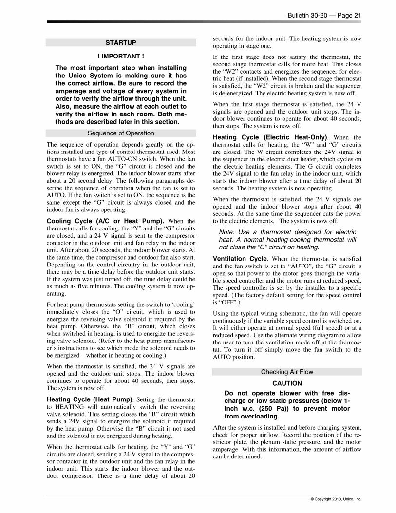
Bulletin 30-20 — Page 21
© Copyright 2010, Unico, Inc.
STARTUP
! IMPORTANT !
The most important step when installing the Unico System is making sure it has the correct airflow. Be sure to record the amperage and voltage of every system in order to verify the airflow through the unit. Also, measure the airflow at each outlet to verify the airflow in each room. Both me-thods are described later in this section.
Sequence of Operation
The sequence of operation depends greatly on the op-tions installed and type of control thermostat used. Most thermostats have a fan AUTO-ON switch. When the fan switch is set to ON, the “G” circuit is closed and the blower relay is energized. The indoor blower starts after about a 20 second delay. The following paragraphs de-scribe the sequence of operation when the fan is set to AUTO. If the fan switch is set to ON, the sequence is the same except the “G” circuit is always closed and the indoor fan is always operating.
Cooling Cycle (A/C or Heat Pump). When the thermostat calls for cooling, the “Y” and the “G” circuits are closed, and a 24 V signal is sent to the compressor contactor in the outdoor unit and fan relay in the indoor unit. After about 20 seconds, the indoor blower starts. At the same time, the compressor and outdoor fan also start. Depending on the control circuitry in the outdoor unit, there may be a time delay before the outdoor unit starts. If the system was just turned off, the time delay could be as much as five minutes. The cooling system is now op-erating.
For heat pump thermostats setting the switch to ‘cooling’ immediately closes the “O” circuit, which is used to energize the reversing valve solenoid if required by the heat pump. Otherwise, the “B” circuit, which closes when switched in heating, is used to energize the revers-ing valve solenoid. (Refer to the heat pump manufactur-er’s instructions to see which mode the solenoid needs to be energized – whether in heating or cooling.)
When the thermostat is satisfied, the 24 V signals are opened and the outdoor unit stops. The indoor blower continues to operate for about 40 seconds, then stops. The system is now off.
Heating Cycle (Heat Pump). Setting the thermostat to HEATING will automatically switch the reversing valve solenoid. This setting closes the “B” circuit which sends a 24V signal to energize the solenoid if required by the heat pump. Otherwise the “B” circuit is not used and the solenoid is not energized during heating.
When the thermostat calls for heating, the “Y” and “G” circuits are closed, sending a 24 V signal to the compres-sor contactor in the outdoor unit and the fan relay in the indoor unit. This starts the indoor blower and the out-door compressor. There is a time delay of about 20
seconds for the indoor unit. The heating system is now operating in stage one.
If the first stage does not satisfy the thermostat, the second stage thermostat calls for more heat. This closes the “W2” contacts and energizes the sequencer for elec-tric heat (if installed). When the second stage thermostat is satisfied, the “W2” circuit is broken and the sequencer is de-energized. The electric heating system is now off.
When the first stage thermostat is satisfied, the 24 V signals are opened and the outdoor unit stops. The in-door blower continues to operate for about 40 seconds, then stops. The system is now off.
Heating Cycle (Electric Heat-Only). When the thermostat calls for heating, the “W” and “G” circuits are closed. The W circuit completes the 24V signal to the sequencer in the electric duct heater, which cycles on the electric heating elements. The G circuit completes the 24V signal to the fan relay in the indoor unit, which starts the indoor blower after a time delay of about 20 seconds. The heating system is now operating.
When the thermostat is satisfied, the 24 V signals are opened and the indoor blower stops after about 40 seconds. At the same time the sequencer cuts the power to the electric elements. The system is now off.
Note: Use a thermostat designed for electric heat. A normal heating-cooling thermostat will not close the “G” circuit on heating.
Ventilation Cycle. When the thermostat is satisfied and the fan switch is set to “AUTO”, the “G” circuit is open so that power to the motor goes through the varia-ble speed controller and the motor runs at reduced speed. The speed controller is set by the installer to a specific speed. (The factory default setting for the speed control is “OFF”.)
Using the typical wiring schematic, the fan will operate continuously if the variable speed control is switched on. It will either operate at normal speed (full speed) or at a reduced speed. Use the alternate wiring diagram to allow the user to turn the ventilation mode off at the thermos-tat. To turn it off simply move the fan switch to the AUTO position.
Checking Air Flow
CAUTION
Do not operate blower with free dis-charge or low static pressures (below 1-inch w.c. (250 Pa)) to prevent motor from overloading.
After the system is installed and before charging system, check for proper airflow. Record the position of the re-strictor plate, the plenum static pressure, and the motor amperage. With this information, the amount of airflow can be determined.
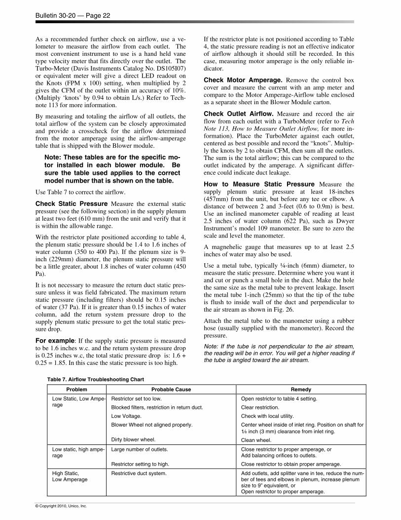
Bulletin 30-20 — Page 22
© Copyright 2010, Unico, Inc.
As a recommended further check on airflow, use a ve-lometer to measure the airflow from each outlet. The most convenient instrument to use is a hand held vane type velocity meter that fits directly over the outlet. The Turbo-Meter (Davis Instruments Catalog No. DS105I07) or equivalent meter will give a direct LED readout on the Knots (FPM x 100) setting, when multiplied by 2 gives the CFM of the outlet within an accuracy of 10%. (Multiply ‘knots’ by 0.94 to obtain L/s.) Refer to Tech-note 113 for more information.
By measuring and totaling the airflow of all outlets, the total airflow of the system can be closely approximated and provide a crosscheck for the airflow determined from the motor amperage using the airflow-amperage table that is shipped with the Blower module.
Note: These tables are for the specific mo-tor installed in each blower module. Be sure the table used applies to the correct model number that is shown on the table.
Use Table 7 to correct the airflow.
Check Static Pressure Measure the external static pressure (see the following section) in the supply plenum at least two feet (610 mm) from the unit and verify that it is within the allowable range.
With the restrictor plate positioned according to table 4, the plenum static pressure should be 1.4 to 1.6 inches of water column (350 to 400 Pa). If the plenum size is 9-inch (229mm) diameter, the plenum static pressure will be a little greater, about 1.8 inches of water column (450 Pa).
It is not necessary to measure the return duct static pres-sure unless it was field fabricated. The maximum return static pressure (including filters) should be 0.15 inches of water (37 Pa). If it is greater than 0.15 inches of water column, add the return system pressure drop to the supply plenum static pressure to get the total static pres-sure drop.
For example: If the supply static pressure is measured to be 1.6 inches w.c. and the return system pressure drop is 0.25 inches w.c, the total static pressure drop is: 1.6 + 0.25 = 1.85. In this case the static pressure is too high.
If the restrictor plate is not positioned according to Table 4, the static pressure reading is not an effective indicator of airflow although it should still be recorded. In this case, measuring motor amperage is the only reliable in-dicator.
Check Motor Amperage. Remove the control box cover and measure the current with an amp meter and compare to the Motor Amperage-Airflow table enclosed as a separate sheet in the Blower Module carton.
Check Outlet Airflow. Measure and record the air flow from each outlet with a TurboMeter (refer to Tech Note 113, How to Measure Outlet Airflow, for more in-formation). Place the TurboMeter against each outlet, centered as best possible and record the “knots”. Multip-ly the knots by 2 to obtain CFM, then sum all the outlets. The sum is the total airflow; this can be compared to the outlet indicated by the amperage. A significant differ-ence could indicate duct leakage.
How to Measure Static Pressure Measure the supply plenum static pressure at least 18-inches (457mm) from the unit, but before any tee or elbow. A distance of between 2 and 3-feet (0.6 to 0.9m) is best. Use an inclined manometer capable of reading at least 2.5 inches of water column (622 Pa), such as Dwyer Instrument’s model 109 manometer. Be sure to zero the scale and level the manometer.
A magnehelic gauge that measures up to at least 2.5 inches of water may also be used.
Use a metal tube, typically ¼-inch (6mm) diameter, to measure the static pressure. Determine where you want it and cut or punch a small hole in the duct. Make the hole the same size as the metal tube to prevent leakage. Insert the metal tube 1-inch (25mm) so that the tip of the tube is flush to inside wall of the duct and perpendicular to the air stream as shown in Fig. 26.
Attach the metal tube to the manometer using a rubber hose (usually supplied with the manometer). Record the pressure.
Note: If the tube is not perpendicular to the air stream, the reading will be in error. You will get a higher reading if the tube is angled toward the air stream.
Table 7. Airflow Troubleshooting Chart
Problem Probable Cause Remedy
Low Static, Low Ampe-rage
Restrictor set too low.
Blocked filters, restriction in return duct.
Low Voltage.
Blower Wheel not aligned properly.
Dirty blower wheel.
Open restrictor to table 4 setting.
Clear restriction.
Check with local utility.
Center wheel inside of inlet ring. Position on shaft for 1/8 inch (3 mm) clearance from inlet ring.
Clean wheel.
Low static, high ampe-rage
Large number of outlets.
Restrictor setting to high.
Close restrictor to proper amperage, or Add balancing orifices to outlets.
Close restrictor to obtain proper amperage.
High Static, Low Amperage
Restrictive duct system. Add outlets, add splitter vane in tee, reduce the num-ber of tees and elbows in plenum, increase plenum size to 9” equivalent, or Open restrictor to proper amperage.
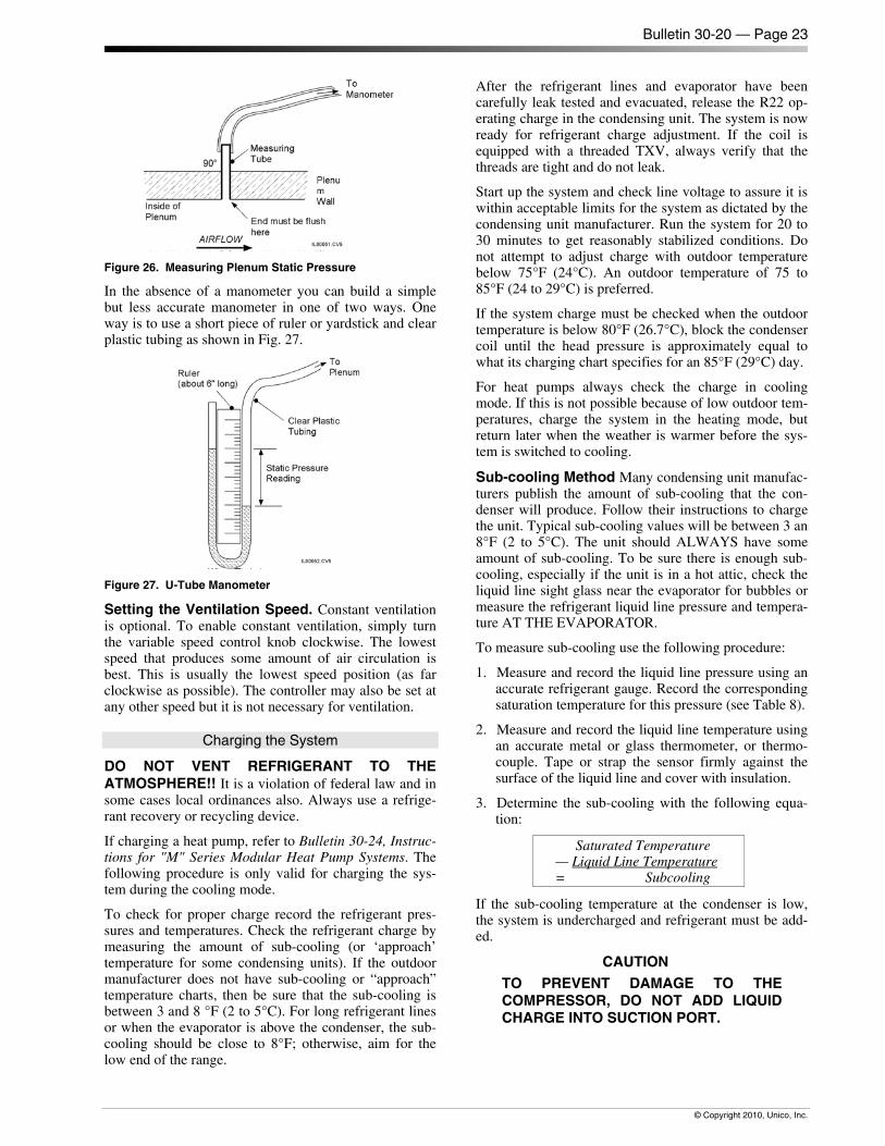
Bulletin 30-20 — Page 23
© Copyright 2010, Unico, Inc.
Figure 26. Measuring Plenum Static Pressure
In the absence of a manometer you can build a simple but less accurate manometer in one of two ways. One way is to use a short piece of ruler or yardstick and clear plastic tubing as shown in Fig. 27.
Figure 27. U-Tube Manometer
Setting the Ventilation Speed. Constant ventilation is optional. To enable constant ventilation, simply turn the variable speed control knob clockwise. The lowest speed that produces some amount of air circulation is best. This is usually the lowest speed position (as far clockwise as possible). The controller may also be set at any other speed but it is not necessary for ventilation.
Charging the System
DO NOT VENT REFRIGERANT TO THE ATMOSPHERE!! It is a violation of federal law and in some cases local ordinances also. Always use a refrige-rant recovery or recycling device.
If charging a heat pump, refer to Bulletin 30-24, Instruc-tions for "M" Series Modular Heat Pump Systems. The following procedure is only valid for charging the sys-tem during the cooling mode.
To check for proper charge record the refrigerant pres-sures and temperatures. Check the refrigerant charge by measuring the amount of sub-cooling (or ‘approach’ temperature for some condensing units). If the outdoor manufacturer does not have sub-cooling or “approach” temperature charts, then be sure that the sub-cooling is between 3 and 8 °F (2 to 5°C). For long refrigerant lines or when the evaporator is above the condenser, the sub-cooling should be close to 8°F; otherwise, aim for the low end of the range.
After the refrigerant lines and evaporator have been carefully leak tested and evacuated, release the R22 op-erating charge in the condensing unit. The system is now ready for refrigerant charge adjustment. If the coil is equipped with a threaded TXV, always verify that the threads are tight and do not leak.
Start up the system and check line voltage to assure it is within acceptable limits for the system as dictated by the condensing unit manufacturer. Run the system for 20 to 30 minutes to get reasonably stabilized conditions. Do not attempt to adjust charge with outdoor temperature below 75°F (24°C). An outdoor temperature of 75 to 85°F (24 to 29°C) is preferred.
If the system charge must be checked when the outdoor temperature is below 80°F (26.7°C), block the condenser coil until the head pressure is approximately equal to what its charging chart specifies for an 85°F (29°C) day.
For heat pumps always check the charge in cooling mode. If this is not possible because of low outdoor tem-peratures, charge the system in the heating mode, but return later when the weather is warmer before the sys-tem is switched to cooling.
Sub-cooling Method Many condensing unit manufac-turers publish the amount of sub-cooling that the con-denser will produce. Follow their instructions to charge the unit. Typical sub-cooling values will be between 3 an 8°F (2 to 5°C). The unit should ALWAYS have some amount of sub-cooling. To be sure there is enough sub-cooling, especially if the unit is in a hot attic, check the liquid line sight glass near the evaporator for bubbles or measure the refrigerant liquid line pressure and tempera-ture AT THE EVAPORATOR.
To measure sub-cooling use the following procedure:
1. Measure and record the liquid line pressure using an accurate refrigerant gauge. Record the corresponding saturation temperature for this pressure (see Table 8).
2. Measure and record the liquid line temperature using an accurate metal or glass thermometer, or thermo-couple. Tape or strap the sensor firmly against the surface of the liquid line and cover with insulation.
3. Determine the sub-cooling with the following equa-tion:
Saturated Temperature — Liquid Line Temperature = Subcooling
If the sub-cooling temperature at the condenser is low, the system is undercharged and refrigerant must be add-ed.
CAUTION TO PREVENT DAMAGE TO THE COMPRESSOR, DO NOT ADD LIQUID CHARGE INTO SUCTION PORT.
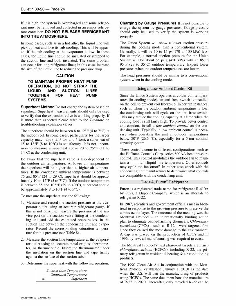
Bulletin 30-20 — Page 24
© Copyright 2010, Unico, Inc.
If it is high, the system is overcharged and some refrige-rant must be removed and collected in an empty refrige-rant container. DO NOT RELEASE REFRIGERANT INTO THE ATMOSPHERE.
In some cases, such as in a hot attic, the liquid line will pick up heat and lose its sub-cooling. This will be appar-ent if the sub-cooling at the evaporator is low. In these cases, the liquid line should be insulated or strapped to the suction line and both insulated. The same problem can occur for long refrigerant lines; in this case, increase the size of the liquid line to reduce the pressure drop.
CAUTION TO MAINTAIN PROPER HEAT PUMP OPERATION, DO NOT STRAP THE LIQUID AND SUCTION LINES TOGETHER FOR HEAT PUMP SYSTEMS.
Superheat Method Do not charge the system based on superheat. Superheat measurements should only be used to verify that the expansion valve is working properly. If is more than expected please refer to the Technote on troubleshooting expansion valves.
The superheat should be between 8 to 12°F (4 to 7°C) at the indoor coil. In some cases, particularly for the larger capacity match-ups (i.e. 3 ton and 5 ton), a superheat of 15 to 18°F (8 to 10°C) is satisfactory. It is not uncom-mon to measure a superheat above 20 to 25°F (11 to 14°C) at the condensing unit.
Be aware that the superheat value is also dependent on the outdoor air temperature. At lower air temperatures the superheat will be higher than at higher air tempera-tures. If the condenser ambient temperature is between 75 and 85°F (24 to 29°C), superheat should be approx-imately 10 to 12°F (5 to 7°C). If the outdoor temperature is between 85 and 105°F (29 to 40°C), superheat should be approximately 8 to 10°F (4 to 5°C).
To measure the superheat, use the following:
1. Measure and record the suction pressure at the eva-porator outlet using an accurate refrigerant gauge. If this is not possible, measure the pressure at the ser-vice port on the suction valve fitting at the condens-ing unit and add the estimated pressure loss in the suction line between the condensing unit and evapo-rator. Record the corresponding saturation tempera-ture for this pressure (see Table 8).
2. Measure the suction line temperature at the evapora-tor outlet using an accurate metal or glass thermome-ter, or thermocouple. Insert the thermometer under the insulation on the suction line and tape firmly against the surface of the suction tube.
3. Determine the superheat with the following equation:
Suction Line Temperature — Saturated Temperature = Superheat
Charging by Gauge Pressures It is not possible to charge the system by gauge pressures. Gauge pressure should only be used to verify the system is working properly
The Unico System will show a lower suction pressure during the cooling mode than a conventional system. Generally, it will be 10 to 15 psi (70 to 100 kPa) less. For example, a normal suction pressure for the Unico System will be about 65 psig (450 kPa) with an 85 to 95°F (29 to 35°C) outdoor temperature. Expect lower pressures when the outdoor temperatures are lower.
The head pressures should be similar to a conventional system when in the cooling mode.
Using a Low Ambient Control Kit
Since the Unico System operates at colder coil tempera-tures (in cooling mode), an anti-frost switch is installed on the coil to prevent coil freeze-up. In certain instances, such as when the outdoor ambient temperature is low, the condensing unit will cycle on the anti-frost switch. This may reduce the cooling capacity at a time when the cooling load is still fairly high. To provide better control and comfort, install a low ambient control on the con-densing unit. Typically, a low ambient control is neces-sary when operating the unit at outdoor temperatures below 80°F (26.6 °C), especially for a 5-ton nominal capacity system.
These controls come in different configurations such as the Hoffman Controls Corp. series 800AA-head pressure control. This control modulates the outdoor fan to main-tain a minimum liquid line temperature. Other controls may cycle the fan on/off. In either case check with the condensing unit manufacturer to determine what controls are compatible with the condensing unit.
R-410A, Puron© Refrigerant
Puron is a registered trade name for refrigerant R-410A by Suva, a Dupont Company, which is an alternate to refrigerant R-22.
In 1987, scientists and government officials met in Mon-treal in response to the growing pressure to preserve the earth's ozone layer. The outcome of the meeting was the Montreal Protocol - an internationally binding action plan to eliminate ozone-harming chemicals. Chlorofluo-rocarbons (CFCs) - such as R-12 - were targeted first since they caused the most damage to the environment. A cap was placed on the production of CFC's and in 1996, by law, all manufacturing was required to cease.
The Montreal Protocol's next phase-out targets are hydro chlorofluorocarbons (HCFCs), including R-22, the pri-mary refrigerant in residential heating & air conditioning products.
The 1990 Clean Air Act in conjunction with the Mon-treal Protocol, established January 1, 2010 as the date when the U.S. will ban the manufacturing of products using HCFCs. The same document bans the manufacture of R-22 in 2020. Thereafter, only recycled R-22 can be
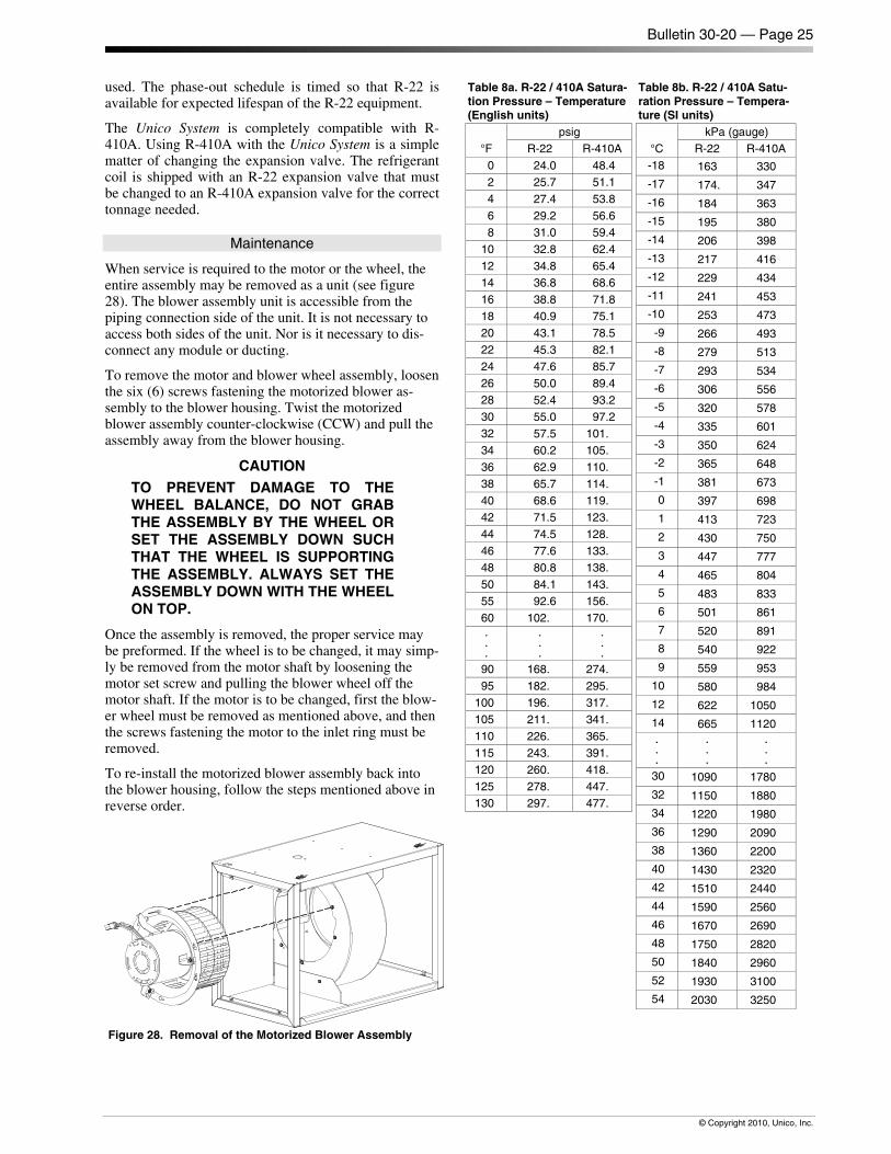
Bulletin 30-20 — Page 25
© Copyright 2010, Unico, Inc.
used. The phase-out schedule is timed so that R-22 is available for expected lifespan of the R-22 equipment.
The Unico System is completely compatible with R-410A. Using R-410A with the Unico System is a simple matter of changing the expansion valve. The refrigerant coil is shipped with an R-22 expansion valve that must be changed to an R-410A expansion valve for the correct tonnage needed.
Maintenance
When service is required to the motor or the wheel, the entire assembly may be removed as a unit (see figure 28). The blower assembly unit is accessible from the piping connection side of the unit. It is not necessary to access both sides of the unit. Nor is it necessary to dis-connect any module or ducting.
To remove the motor and blower wheel assembly, loosen the six (6) screws fastening the motorized blower as-sembly to the blower housing. Twist the motorized blower assembly counter-clockwise (CCW) and pull the assembly away from the blower housing.
CAUTION TO PREVENT DAMAGE TO THE WHEEL BALANCE, DO NOT GRAB THE ASSEMBLY BY THE WHEEL OR SET THE ASSEMBLY DOWN SUCH THAT THE WHEEL IS SUPPORTING THE ASSEMBLY. ALWAYS SET THE ASSEMBLY DOWN WITH THE WHEEL ON TOP.
Once the assembly is removed, the proper service may be preformed. If the wheel is to be changed, it may simp-ly be removed from the motor shaft by loosening the motor set screw and pulling the blower wheel off the motor shaft. If the motor is to be changed, first the blow-er wheel must be removed as mentioned above, and then the screws fastening the motor to the inlet ring must be removed.
To re-install the motorized blower assembly back into the blower housing, follow the steps mentioned above in reverse order.
Figure 28. Removal of the Motorized Blower Assembly
Table 8a. R-22 / 410A Satura-tion Pressure – Temperature (English units)
°F psig
R-22 R-410A 0 24.0 48.4 2 25.7 51.1 4 27.4 53.8 6 29.2 56.6 8 31.0 59.4
10 32.8 62.4 12 34.8 65.4 14 36.8 68.6 16 38.8 71.8 18 40.9 75.1 20 43.1 78.5 22 45.3 82.1 24 47.6 85.7 26 50.0 89.4 28 52.4 93.2 30 55.0 97.2 32 57.5 101. 34 60.2 105. 36 62.9 110. 38 65.7 114. 40 68.6 119. 42 71.5 123. 44 74.5 128. 46 77.6 133. 48 80.8 138. 50 84.1 143. 55 92.6 156. 60 102. 170. . . .
.
.
.
.
.
.
90 168. 274. 95 182. 295.
100 196. 317. 105 211. 341. 110 226. 365. 115 243. 391. 120 260. 418. 125 278. 447. 130 297. 477.
Table 8b. R-22 / 410A Satu-ration Pressure – Tempera-ture (SI units)
°C kPa (gauge)
R-22 R-410A -18 163 330
-17 174. 347
-16 184 363
-15 195 380
-14 206 398
-13 217 416
-12 229 434
-11 241 453
-10 253 473
-9 266 493
-8 279 513
-7 293 534
-6 306 556
-5 320 578
-4 335 601
-3 350 624
-2 365 648
-1 381 673
0 397 698
1 413 723
2 430 750
3 447 777
4 465 804
5 483 833
6 501 861
7 520 891
8 540 922
9 559 953
10 580 984
12 622 1050
14 665 1120 . . .
.
.
.
.
.
.
30 1090 1780
32 1150 1880
34 1220 1980
36 1290 2090
38 1360 2200
40 1430 2320
42 1510 2440
44 1590 2560
46 1670 2690
48 1750 2820
50 1840 2960
52 1930 3100
54 2030 3250
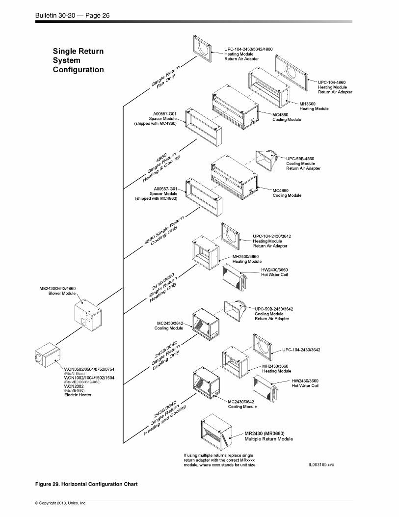
Bulletin 30-20 — Page 26
© Copyright 2010, Unico, Inc.
Figure 29. Horizontal Configuration Chart
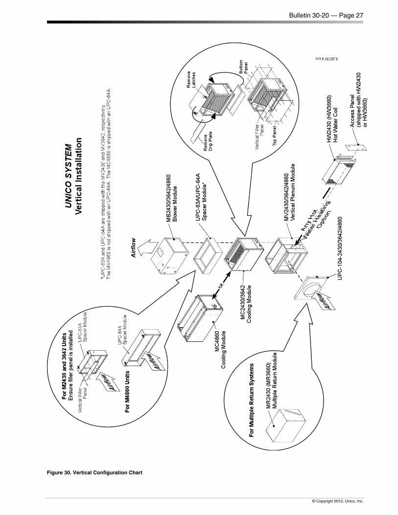
Bulletin 30-20 — Page 27
© Copyright 2010, Unico, Inc.
Figure 30. Vertical Configuration Chart
Bulletin 30-20 — Page 28
© Copyright 2010, Unico, Inc.
PAGE INTENTIONALLY LEFT BLANK