11
I DE Einbauanleitung Dezentrales Lüftungssystem mit Wärmerückgewinnung Typen e², e²kurz und e²neo - Bitte an den Nutzer weiterleiten -
II EN Installation Manual Decentralised Ventilation System with Heat Recovery Type e², e²short and e²neo
- Please pass on to user -

12
Contents Page:
About this manual, Safety instructions, Technical specifications, Disposal 12 Dimension diagrams, Installation position 13 Operating range, Shipping units 14 Assembly: Assembly pipe and Outer grille 15 Assembly: Electric installation and Electric connection 16 Assembly: Heat recovery unit and Inner screen 17 Assembly: Sound insulation set 18 Replacement of ALD-R 160 by e², Note on LUNOS Outer covers 18 Filter replacement, Cleaning, Additional parts and Replacement parts 19
About this manual
Read this manual carefully and completely before assembly. Always observe the general safety
instructions and the safety symbols with information in the text.
Hand out this manual to the user (tenants, proprietors, property management etc.) after comple-
ting assembly. Symbols in this manual
This symbol warns you against risks of injury
This symbol warns you against risks of injury from electricity
Safety instructions
Caution! Any assembly work to the ventilation device may only be carried out after dis-connecting all poles of the supply voltage. The ventilation device is fitted with protective insula-tion according to Protection Class II, a protective conductor connection is not required.
Attention! The electric connection may only be made by authorised qualified personnel and according to the applicable version of VDE 0100.
Attention! This device must not be operated by children and persons (filter replacement/cleaning) who are not able to operate the device safely due to their physical, sensory or mental abilities or their inexperience or lack of knowledge. Children should be supervised to ensure that they do not play with the device.
Technical specifications
Device voltage 12 V DC SELV Type of protection IP 22 Volume flow 18 m³/h to 38 m³/h possible Enveloping surface sound pressure level 16.5 dB at 18 m³/h; 19.5 dB at 31 m³/h
Disposal
The packaging must be sorted before disposal. If you wish to dispose of the ventilation device, observe the current regulations. The competent municipal authority will provide information.
Installation Manual EN

13
1m
Dimension diagrams (all dimensions in mm) EN
Installation position
Decentralised ventilation devices with heat recovery of the type e² only function in pairs in bidirectional operation. One device operates 70 s (50s for e² short) in supply air operation, the other 70 s (50 s for e²short) in exhaust air operation at the corresponding airflow level as set. Then the air direction is changed. It is thus ensured that the total of the airflow volume supplied is equal to the total exhaust airflow volume. If a device pair operating in push-pull operation is installed and operated in two diffe-rent rooms of the flat, a sufficiently dimensioned interconnection between the air movement must be provided by excess flow air vents.
Recommended minimum spacing when installing a pair of devices in a wall:
Recommended minimum spacing when installing a pair of devices across a corner:
1 m
1,4m
1m
35 300 - 700 17 180
180
Dimensions in mm 200* –300
e²short :
Do not place the devices above sensitive pieces of furniture, surfaces or pictures. The wall underneath the devices should be left “free“. Do not place the devices above or near room thermostats.
DA 160
Heat exchanger
Heat exchanger EPP ring
*Shorten EPP ring if necessary

14
Type 1/WE 180 white Order No.: 39 852 Type 1/GE 180 light grey Order No.: 39 853 Type 1/RE 180 red-brown Order No.: 39 854
Alternative external closures see pricelist or on request
Shipping units
Check the supplies for completeness and mint condition!
Assembly pipe Outer grille
Insert e² Inner screen
Pipe DA 160 mm
Plaster protection cap
The outer grille 1/W 180 is supplied together with the facade protection ring 1/FSR 180. A correspon-ding installation manual is enclosed.
Operating range EN
Filter (included in the supply unit built-in device e²)
Alternative inner screens see pricelist or on request
Temperature range: -15°C to +40°C Usable with relative humidity levels of up to 65% in the interior area. During heating periods low levels of condensate formation may occur. When usage limits are exceeded, switch off the device and close the inner screen. Ensure fresh air supply by window ventilation.

15
Further outer grilles available on request
Assembly: Assembly pipe and outer grille EN
Make the wall openings for the as-sembly pipes (e.g. by coring, core bit Ø 162 mm). If necessary shorten the pipe to the required installation length (e²: min. 300 mm; e²short: min. 200 mm). Take care that the pipe overlaps on both sides to cope with the plaster thicknesses (after plastering the pipe must close flush with the plaster). Insert the pipe and seal it all around. (Assembly glue Order No. 038 733).
Apply plaster indoors and outdoors. If outer closure is plastered, first replace the plaster protection cap outdoors by an outdoor closure piece.
Remove the plaster protection cap outdoors. Assemble the outer grille using the integrated claw fasteners (tighten screws).
①
②
➂
Indoors
Indoors Outdoors
Outdoors
Plaster protection cap
Tighten claw fasteners with screws
3 m
m

16
Assembly: Electric installation and Electric connection EN
Safety instructions: Caution! Any assembly work to the ventilation device may only be carried out when all poles of the supply voltage have been disconnected. Make sure that the supply voltage of all connection lines is voltage-free (dead). (Separation from the power supply with a minimum contact opening of 3 mm, e.g. electric fuse disconnecting all poles).
Each electric circuit of this ventilation system must be fitted with a residual current protection (e.g. FI switch/RCCB).
Electric connection only by a specialist. Additional installations and electrical components in this ventilation system are not allowed.
The system can be controlled via several controls of LUNOS. Follow the relevant installation instructions. Select the position of the switch. Slit the cable ducts (power cable + cable to the device pairs) and the pipes (2 cm deep). Lay the power cable (e.g. 3 x 1.5 mm²) and the cables to the pairs of devices (e.g. 3 x 0.75 mm²). Place the cables to the device pairs ready in the pipes. Circuit and switch are connected as shown in the diagram below.
➃
Power cable
Switch
Device 1 Supply/Exhaust
Device 2 Exhaust/Supply
horizontal
vertical
also slit pipes for cable
Only slit the pipes in these four areas
Connector box

17
Assembly: Heat recovery unit and Inner screen EN
Remove plaster protection cap inside, insert heat exchanger unit into the assembly pipe, ensure there is a 22 mm spacing. Motor is on the inside. Using the loop on the inside of the heat exchanger unit the said unit may be pulled out for correction purposes.
Connect cables to plugs, insert pin and socket connectors into the recess of the heat exchanger casing.
⑦
Motor
22 mm
Cable Motor cable red
blue
purple
Pin-and-socket connector
⑥
Insert inner closure with filter casing, snap the indoor screen into place in open position. Ready.
open
closed
⑧
18
Replacement of ALD-R 160 by e²
L min
1 2
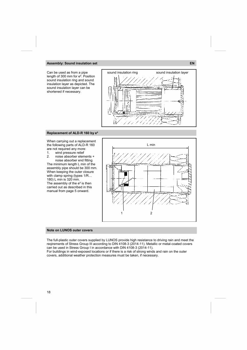
When carrying out a replacement the following parts of ALD-R 160 are not required any more: 1. wind pressure relief 2. noise absorber elements + noise absorber end fitting The minimum length L min of the assembly pipe should be 300 mm. When keeping the outer closure with clamp spring (types 1/R… 180) L min is 320 mm. The assembly of the e² is then carried out as described in this manual from page 5 onward.
Assembly: Sound insulation set EN
Can be used as from a pipe length of 300 mm for e². Position sound insulation ring and sound insulation layer as depicted. The sound insulation layer can be shortened if necessary.
sound insulation ring sound insulation layer
Note on LUNOS outer covers
The full-plastic outer covers supplied by LUNOS provide high resistance to driving rain and meet the reqirements of Stress Group III according to DIN 4108-3 (2014-11). Metallic or metal-coated covers can be used in Stress Group I in accordance with DIN 4108-3 (2014-11). For buildings in wind-exposed locations or if there is a risk of strong winds and rain on the outer covers, additional weather protection measures must be taken, if necessary.
19
Filter replacement date Expected filter replacement Type of filter used
Please note below information on the filter changes you have carried out:
Filter replacement EN
LED iIluminates beneath the switch
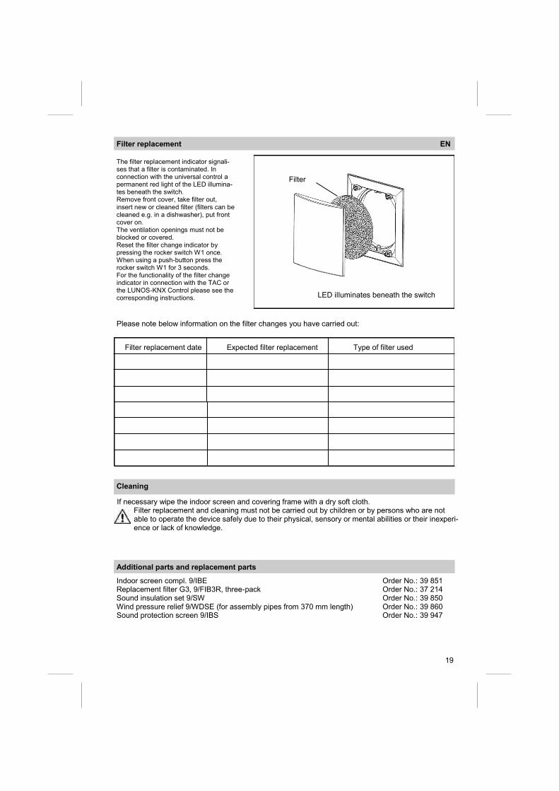
The filter replacement indicator signali-ses that a filter is contaminated. In connection with the universal control a permanent red light of the LED illumina-tes beneath the switch. Remove front cover, take filter out, insert new or cleaned filter (filters can be cleaned e.g. in a dishwasher), put front cover on. The ventilation openings must not be blocked or covered. Reset the filter change indicator by pressing the rocker switch W1 once. When using a push-button press the rocker switch W1 for 3 seconds. For the functionality of the filter change indicator in connection with the TAC or the LUNOS-KNX Control please see the corresponding instructions.
Cleaning
If necessary wipe the indoor screen and covering frame with a dry soft cloth. Filter replacement and cleaning must not be carried out by children or by persons who are not able to operate the device safely due to their physical, sensory or mental abilities or their inexperi-ence or lack of knowledge.
Additional parts and replacement parts
Filter
Indoor screen compl. 9/IBE Order No.: 39 851 Replacement filter G3, 9/FIB3R, three-pack Order No.: 37 214 Sound insulation set 9/SW Order No.: 39 850 Wind pressure relief 9/WDSE (for assembly pipes from 370 mm length) Order No.: 39 860 Sound protection screen 9/IBS Order No.: 39 947

20
E1
24
06
.16
Assembly – electric installation and electric connection EN
Safety instructions: Beware! Any assembly work to the ventilation device may only be carried out when all phases of supply voltage have been disconnected!
Make sure that the supply voltage of all connection lines is dead! (separation from the power supply with a free space between contacts of at least 3 mm, e.g. all-phase disconnecting electr. protection).
Each electric circuit of this ventilation system must be fitted with a residual current protection (e.g. RCD)!
WARNING – TO REDUCE THE RISK OF FIRE, ELECTRIC SHOCK, OR
INJURY TO PERSONS, OBSERVE THE FOLLOWING:
a.) Installation work and electrical wiring must be done by qualified person(s)
in accordance with all applicable codes and standards, including fire-rated
construction.
b.) Sufficient air is needed for proper combustion and exhausting of gases
through the flue (chimney) of fuel burning equipment to prevent back
drafting. Follow the heating equipment manufacturer’s guideline and safety
standards such as those published by the National Fire Protection Association
(NFPA), and the American Society for Heating, Refrigeration and Air
Conditioning Engineers (ASHRAE), and the local code authorities.
c.) When cutting or drilling into wall or ceiling, do not damage electrical
wiring and other hidden utilities.
d.) Ducted fans must always be vented to the outdoors.
e.) If this unit is to be installed over a tub or shower, it must be marked as
appropriate for the application and be connected to a GFCI (Ground Fault
Circuit Interrupter) – protected branch circuit.
The product’s installation shall not conflict with any requirement in the National Electrical Code,
ANSI/NFPA 70-1999.
Additional installations and electrical components in this ventilation system are prohibited!
LUNOS Germany
LUNOS Lüftungstechnik GmbH Phone +49 30 362 001-0 für Raumluftsysteme Fax +49 30 362 001-89 Wilhelmstr. 31 [email protected] 13593 Berlin ∙ Germany www.lunos.de