TABLE OF CONTENTS
CLEVELAND, OHIO USAPHONE (216) 206-4200 • FAX (216) 206-4242
PAGE
Hellan Strainer Benefits 1
Quality Assurance and Product Testing 2
Codes and Standards Compliance 3
Typical Applications 4-5
Unique Strainer Operation 6-7
Strainer Types 8-10
Selecting a Strainer 11-12
Screen Options 13
Sizes, Body Materials and Flange Options 14
Pressure Ratings and Flow Rates 15
Component Materials 16-17
Automatic Operation Options 18-19
Dimensional Information 20-53
Pressure Drop vs. Flow Rate Curves 54-81
Model Number Specification 82-83
Sample Specification Document 84
CLEVELAND, OHIO USAPHONE (216) 206-4200 • FAX (216) 206-4242HTTP://WWW.HELLANSTRAINER.COM

1
BENEFITS OF THE HELLAN STRAINER
CLEVELAND, OHIO USAPHONE (216) 206-4200 • FAX (216) 206-4242
REMOVE SOLIDS WITHOUT STOPPING THE FLOW
Instead of trapping solids in a basket which must then beremoved for frequent clean-outs, the Hellan Strainer removessolids from the fluid flow without stopping the flow or disas-sembling the strainer. A simple turn of the hand wheel (oractuation of the screen motor in automatic units) rotates thescreen against a scraper bar. Debris moves to a sump areawhere it is removed by periodic flushing.
LOW OPERATING COSTS
Removing solids from the screen takes about thirty seconds,compared to one or two hours for a basket strainer. Laborcosts can be completely eliminated with our automatic self-cleaning strainer.
SAFETY FOR EMPLOYEE PERSONNEL
The Hellan Strainer closed system protects personnel from contact with strained debris that may include contaminants orhazardous materials.
HIGH QUALITY CONSTRUCTION
Hellan Strainers are designed and built to ANSI/ASQCStandard Q94-1987. Each strainer is proof pressure tested to150% MAWP, per ASME standards, before shipment. QualityAssurance and manufacturing systems are registered for compliance with ISO-9001 International Standard.
MEET OR EXCEED MAJOR U.S.AND INTERNATIONAL STANDARDS
Hellan Strainers are available in models that comply withmajor U.S. industrial codes and standards, including ASME,the American Bureau of Shipping, Lloyd’s Register, and theFluid Control Institute. Select models are listed withUnderwriters Laboratories. Models are also available in compliance with major international standards, includingD.I.N., I.E.C. and Cenelec specifications.
MATERIAL CONSTRUCTION FOR A VARIETYOF APPLICATIONS
Hellan Strainer bodies are available in cast iron, cast steel, caststainless steel, bronze and custom materials to meet thedemands of a wide range of applications.
LOW MAINTENANCE COSTS
While there is no routine disassembly needed with a HellanStrainer, all of the internal components can be changed in lessthan 15 minutes without any special tools. Servicing or partsreplacement is therefore very inexpensive.
LOW INSTALLATION COSTS
A Hellan Strainer weighs about half as much as comparableconventional basket-type strainers and requires about 60% of the space. It may be mounted in-pipeline, in a vertical orhorizontal position. No special foundation is needed andinstallation is simple and less costly.
MANUAL OR AUTOMATIC OPERATION
Hellan Strainers are available in manual or automatic models.A full array of controls is available for remote, automatedoperation of automatic models. Manual models can beupgraded to automatic operation in the field without disruption of the fluid handling system.
LOW CAPITAL INVESTMENT
Hellan Strainers are competitively priced.
QUALITY ASSURANCE AND TESTING TESTING
CLEVELAND, OHIO USAPHONE (216) 206-4200 • FAX (216) 206-4242
2
Hellan Strainers are designed and manufactured under a stringent Tool Quality Management Program. This TQM pro-gram and a continuous improvement policy keep our qualitystandards and procedures among the highest in the industry.Designed to ISO 9001, our quality program directs all aspects ofour business, including procurement, design, manufacturing,inspection and testing.
Every Hellan Strainer is designed and built to ANSI/ASQCStandard Q94-1997. Prior to shipment, each strainer is proofpressure tested to 150% MAWP, per ASME standards.
Our commitment to quality and the unique operating featuresof our strainer design assure our customers that HellanStrainers will provide consistent performance in even the mostchallenging applications.
3
STANDARDS, CERTIFICATION AND PATENTS
CLEVELAND, OHIO USAPHONE (216) 206-4200 • FAX (216) 206-4242
Hellan Strainers are available in models that comply withmajor U.S. and international standards, including those ofthe following organizations:
American Bureau of ShippingAll Hellan Strainers appearing in this cataloghave been certified for service in fuel oil,lube oil, fresh water and sea water service bythe American Bureau of Shipping. ABS hasrated Hellan Strainers for 150 PSI (10.34 bars) MAWP to 740 PSI (51.02 bars)MAWP, depending on flange class, con-struction material and temperature of theprocess fluid.
American Society of Mechanical Engineers (ASME)Hellan Strainers are designed in accordancewith ASME Boiler and Pressure Vessel CodeSection 8. All strainers are proof pressuretested at 150% of their recommended maximum allowable operating pressure.
Fluid Control Institute (FCI)Hellan Strainers are manu-factured in accordance withFCI standard 78-1.
National Fire Sprinkler Association, Inc.Cleveland Gear is a member of the NationalFire Sprinkler Association, Inc.
Underwriters LaboratoriesNon-automatic Hellan Strainers constructedof cast iron, cast steel or cast stainless steelin pipe sizes from 2" through 14" withscreen perforations of 3/32", 1/8" or 3/16"are listed with Underwriters Laboratories(Re-examination service) and are UL listedunder Strainers, Pipe Line (HLCV), File EX1708(N), “Fire Main Pipe Strainer.”
ISO-9001Quality systems certified by Det NorskeVeritas to ISO-9001 International Standard.Certificate No. QSC-4386.
Lloyd’s RegisterHellen Strainers are Type Approved byLloyd’s Register and have met their requirements for use in fresh and salt watersystems (including fire main), fuel oil systems and lubricating oil systems.Certificate No. 01/60001
International StandardsHellan Strainers are available in models the comply with mostinternational standards, including D.I.N., I.E.C. and Cenelecspecifications.
Patent ProtectionHellan Strainers are protected by several patents.
R
APPLICATIONS
CLEVELAND, OHIO USAPHONE (216) 206-4200 • FAX (216) 206-4242
4
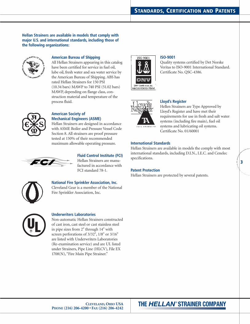
MARINE
Hellan Strainers are used on U.S. Navy ships in sea water cooling of electronic equipment (i.e., sonar, radar, close inweapon systems, etc.), lube oil, firemain systems, and fuel filtration.
PETROLEUM
Hellan Strainers are used on offshore rigs around the world infire protection and filtration systems.
PETROCHEMICAL
Hellan Strainers protect plant equipment (i.e., condensers,spray nozzles, heat exchangers, pumps, etc.) strain coolingtower water, remove polyethylene fines from process water and are used in deluge fire protection systems.

5
APPLICATIONS
CLEVELAND, OHIO USAPHONE (216) 206-4200 • FAX (216) 206-4242
FIRE PROTECTION
Hellan Strainers are U.L. approved for spray nozzle protectionin all types of fire protection systems.
WASTE WATER TREATMENT
Hellan Strainers are used in belt filter presses for protection ofspray nozzles and in secondary effluent systems for protectionof chlorinators, seal water, plant service and foam control.
ETHANOL PLANT
Hellan Strainers are used to protect plate and frame heatexchangers downstream of the slurry tank. Used to capturecorn slurry from caustic solution during cleaning of the slurry tank.
POWER UTILITY PLANTS (FOSSIL, HYDRO & NUCLEAR)Hellan Strainers remove zebra mussels, sand, grit, small fish,etc., from lakes and rivers for protection of plant equipment.Strains water for turbine bearings.
IRON AND STEEL FACILITIES
Hellan Strainers are used in recirculating water, descaling water and cooling water for hot strip and plate mills, blast furnaces, open hearths and continuous casting mills.
IRRIGATION SYSTEMS
Hellan strainers are used in irrigation systems, including golfcourses, to protect spray nozzles by removing debris fromlakes, rivers and ponds.

UNIQUE OPERATING FEATURES
CLEVELAND, OHIO USAPHONE (216) 206-4200 • FAX (216) 206-4242
6
THE HELLAN STRAINER DESIGN PROVIDES SOLIDSREMOVAL WITHOUT INTERRUPTING THE FLUID FLOW
Instead of trapping solids in a basket which then must beremoved for frequent clean-outs, the Hellan Strainer removesthe solids from fluid without stopping the flow or disassembling the strainer. The sequence of operation is illustrated below.
❶ Fluid passes into the strainer and through a screen.
❷ A deflection rib protects the screen from large objects.
❸ The screened fluid flows out of the strainer and into service.
❹ Rotating the screen, by either handwheel or motor,moves the outer screen surface against a scraper bar.The scraper bar removes collected debris from thescreen’s outer surface.
❺ Debris moves to the sump area of the strainer where it isremoved by periodic flushing.
SPECIAL FEATURES PROVIDE CONVENIENCEAND HIGH PERFORMANCE.
❻ Large inspection ports, sealed with O-rings, permit easy,external adjustment of the scraper bar. Multiple screenmodels size 4" and larger, plus 3" single screen models.
❼ O-rings at the screen cover plate and shaft provide atight seal while allowing operation at low torque.
➑ Backwash system is available to remove debris from screen.
➒ Eductor is available at discharge for low-pressure applications.
OPERATING FEATURES THAT PROVIDE REAL BENEFITS
• Eliminate downtime for solids removalThe Hellan Strainer allows users to eliminate solids anddebris from fluids without stopping the flow of the fluid.Processes requiring the fluid continue uninterrupted.
• Employees are not exposed to possible contaminatesDebris that may include contaminates and hazardousmaterials is removed from the fluid flow without disas-sembly of the strainer. Maintenance personnel and otheremployees do not come into contact with this debris.
• Minimum labor requirements for solids removalThe Hellan Strainer reduces the time required to removesolids from the fluid flow. Manually-operated modelsrequire only a periodic turning of the handwheel toremove solids. Labor and cleaning time is usually lessthen 30 seconds. Labor requirements can be completelyeliminated with automatic strainers that can be con-trolled by timers and/or pressure differential switches.
❶
❼
❺
❻
❷
❸❹
TO DRAIN

7
UNIQUE OPERATING FEATURESWDA Type
CLEVELAND, OHIO USAPHONE (216) 206-4200 • FAX (216) 206-4242
❶ Fluid passes into the strainer and thru the screens.
❷ The screened fluid flows out of the strainer.
❸ Rotating the screen, by motor, moves the outer screen surface against the scraper bar. The scraper bar dislodges and removes collected debris from the screen’s outer surface.
❹ While the screen is rotating, the drain is opened and the debris is sucked out through the drain in use.
❺ A drain separator is used to prevent the fluid velocity from pulling the debris away from the drain tube opening.
❻ Large inspection ports, sealed with O-rings, permit easy,external adjustment of the scraper bars and drain separators.
❼ O-rings at the screen shaft provide a tight seal while allowing operation at low torque.
❶
❶
❶
❼
❺❻
❷
❸
❹
❹
❹

STRAINER TYPES
CLEVELAND, OHIO USAPHONE (216) 206-4200 • FAX (216) 206-4242
8
HELLA
N
U.S. PA
TENT
No. RE
35560
ASTM A
278-64 C
LASS
30
MARKFO
UNDRY
HEAT
CODE
FOUNDRY
U.S. PA
TENT
No. RE
35560
ASTM A
278-64 C
LASS
30
HELLA
N
MARK
HEAT
CODE
INLINE FLOW BODY-SINGLE SCREEN
• Inline Flow, Manual Strainers (Type TSH) (Single ManualRotating Screen) (Sizes 1-1/2", 2", 2-1/2", 3") Type TSHHellan strainer employ a single handwheel equipped rotat-ing screen and a rigid scraper bar to remove solids from thesurface of the screen when the handwheel is rotated. A solidscollecting sump is also provided. Cleaning of the Type TSHis accomplished by opening a valve on the sump flush connection and rotating the handwheel several times. Thecleaning cycle must be performed when the strainer is undera positive pressure. Type TSH strainer is preferably installedin the horizontal position, as illustrated.
• Inline Flow, Automatic Strainers (Type TSA) (SingleMotorized Rotating Screen) (Sizes 1-1/2", 2", 2-1/2", 3")Type TSA Hellan strainers employ a single, electric motor-driven rotating screen and a rigid scraper bar to removesolids from the surface of the screen when the screen isrotated. A solids collecting sump is also provided. Cleaningof the Type TSA is initiated when the motor and flush valveoperator are actuated. Controls to accomplish these electri-cal functions are provided. The cleaning cycle must be performed when the strainer is under a positive pressure.The Type TSA strainer is preferably installed in the horizontal position, as illustrated.
ANGLED FLOW BODY-SINGLE SCREEN
• Angled Flow, Manual Strainers (Type AH) (Single ManualRotating Screen) (Sizes 2", 2-1/2", 3") Type AH HellanStrainers employ a single hand-wheel equipped rotatingscreen and a rigid scraper bar to remove solids from the surface of the screen when the handwheel is rotated. A solidscollecting sump is also provided. Cleaning of the Type AH isaccomplished by opening a valve on the sump flush connec-tion and rotating the handwheel several times. The cleaningcycle must be performed when the strainer is under a positive pressure. Type AH strainers are preferably installedin the vertical up-flow position, as illustrated.
• Angled Flow, Automatic Strainers (Type AA) (SingleMotorized Rotating Screen) (Size 3" Only) Type AA HellanStrainers employ a single, electric motor-drive rotatingscreen and a rigid scraper bar to remove solids from the surface of the screen when the screen is rotated. A solids collecting sump is also provided. Cleaning of the Type AA isinitiated when the motor and the flush valve operator areactuated. Controls to accomplish these electrical functionsare provided. The cleaning cycle must be performed whenthe strainer is under a positive pressure. The Type AA strainer is preferably installed in the vertical up-flow position, as illustrated.
➧
➧
➧
➧

9
STRAINER TYPESContinued
CLEVELAND, OHIO USAPHONE (216) 206-4200 • FAX (216) 206-4242
INLINE FLOW BODY-TWO SCREENS
• Inline Flow, Manual Strainers (Type DH) (Two ManualRotating Screens) (Sizes 2-1/2", 3", 4", 6", 8", 10", 12")Type DH Hellan Strainers employ two handwheel-equippedrotating screens and rigid scraper bars to remove solids fromthe surface of the screens when the handwheels are rotated.A solids-collecting sump is also provided. Cleaning of theType DH strainer is accomplished by opening a valve on thesump flush connection and rotating the handwheels severaltimes. The cleaning cycle must be performed when thestrainer is operating under a positive pressure. Type DHstrainers can be installed in the vertical up-flow position orin the horizontal flow position with both screens in the horizontal plane and the sump flush connection preferablylocated at the bottom.
• Inline Flow, Automatic Strainers (Type DA) (Two Motor-ized Rotating Screens) (Sizes 4", 6", 8", 10", 12") Type DAHellan Strainers employ two electric motor-driven rotatingscreens and rigid scraper bars to remove solids from the surface of the screens when the screens are rotated. A solids-collecting sump is also provided. Cleaning of the Type DAstrainer is initiated when the motors and the flush valveoperator are actuated. Controls to accomplish these electri-cal functions are provided. The cleaning cycle must be performed when the strainer is operating under a positivepressure. Type DA strainers can be installed in the verticalup-flow position or in the horizontal flow position withboth screens in the horizontal plane and the sump flushconnection preferably located at the bottom.
INLINE FLOW BODY-ONE SCREEN
• Inline Flow, Automatic Strainers (Type WDA) (Two Motor-ized Rotating Screens) (Sizes 20", 24", 30", 36") and (TypeSA) (One Motorized Rotating Screen) (Sizes 14" and 16")These Hellan Strainers employ two electric motor-drivenrotating screens and rigid scraper bars to remove solids fromthe surface of the screens when the screens are rotated.A solids collecting sump is also provided. Cleaning of thestrainer is initiated when the motors and the flush valveoperator are actuated. Controls to accomplish these electri-cal functions are provided. The cleaning cycle must be performed when the strainer is operating under a positivepressure. Type WDA strainers can be installed only in a horizontal flow position with the sump connection locatedat the bottom.
➧ ➧
NAMEPLATE
➧ ➧

STRAINER TYPESContinued
CLEVELAND, OHIO USAPHONE (216) 206-4200 • FAX (216) 206-4242
10
INLINE FLOW BODY-FOUR SCREENS
• Inline Flow, Manual Strainers (Type QH) (Four RotatingScreens*) (Sizes 14" and 16") Type QH Hellan Strainersemploy four handwheel-equipped rotating screens and rigidscraper bars to remove solids from the surface of the screenswhen the handwheels are rotated. A solids-collecting sumpis also provided. Cleaning of the Type QH strainer is accom-plished by opening one or both valves on the two sumpflush outlets and rotating the handwheels several times.The cleaning cycle must be performed when the strainer isoperating under a positive pressure. Type QH strainers arepreferably installed in the vertical up-flow position.
• Inline Flow, Automatic Strainers (Type QA) (Four Motor-ized Rotating Screens*) (Sizes 14" and 16") Type QA HellanStrainers employ four motor-driven rotating screens andrigid scraper bars to remove solids from the surface of thescreens when the motor-driven screens are rotated. A solids-collecting sump is also provided and equipped with twoelectrically-operated flush valves. Cleaning of the Type QAstrainer is initiated when the screen drive motors and flushvalve operators are actuated. Controls to accomplish theseelectrical functions are required. The cleaning cycle must beperformed when the strainer is operating under a positivepressure. Type QA strainers are preferably installed in thevertical up-flow position.
INLINE FLOW BODY-SIX SCREENS
• Inline Flow, Manual Strainers (Type HH) (Six RotatingScreens*) (Size 20" only) Type HH Hellan Strainers employsix handwheel-equipped rotating screens and rigid scraperbars to remove solids from the surface of the screens whenthe handwheels are rotated. A solids-collecting sump is alsoprovided. Cleaning of the Type HH strainer is accomplishedby opening one, two or three valves on the three sump flushoutlets and rotating the handwheels several times. Thecleaning cycle must be performed when the strainer is operating under a positive pressure. Type HH strainers arepreferably installed in the vertical up-flow position.
• Inline Flow, Automatic Strainers (Type HA) (Six Motor-ized Rotating Screens*) (Size 20" only) Type HA HellanStrainers employ six motor driven rotating screens and rigid scraper bars to remove solids from the surface of thescreens when the motor-driven screens are rotated. A solids-collecting sump is also provided and equipped with twoelectrically-operated flush valves. Cleaning of the Type HAstrainer is initiated when the screen drive motors and flushvalve operators are actuated. Controls to accomplish theseelectrical functions are provided. The cleaning cycle must beperformed when the strainer is operating under a positivepressure. Type HA strainers are preferably installed in thevertical up-flow position.

11
HOW TO SELECT A HELLAN STRAINER
CLEVELAND, OHIO USAPHONE (216) 206-4200 • FAX (216) 206-4242
There are six application requirements that should beaddressed when selecting a specific Hellan Strainer model.Here are the considerations and options available for each requirement:
1 PERFORATION SIZE OF THE SCREENS
Hellan recommends that a screen perforation hole diameter be selected that is 40% to 60% of the diameter of the smallestorifice in the system. Selecting a smaller perforation thanrequired leads to unnecessary cleaning cycles and higher pressure drops during operation.
2 SIZE OF THE STRAINER
A) Existing Pipe Size MethodThis method is used when a Hellan Strainer is installed inan existing network of piping. Flow rate and the attendantpressure drop are within the application requirements.
In these situations, it is common practice to select a strainersize that matches the existing pipe size, i.e., an 8" strainerwould be selected for an installation with an existing 8" line.
B) Flow rate requirement versus pressure drop methodThis method should be utilized when selecting a strainer fora new application, or as a replacement strainer in existingsystems where a specific flow rate needs to be maintained.
Refer to the chart at right for flow rates of available strainersizes. Refer to the pressure drop versus flow rate charts forvarious size strainers, appearing on pages 54 through 81.
SCREEN OPTIONS
Perforated Screens Wedge-Wire Screens Round Opening Size Slot Width
Fractional Decimal Metric Mesh Micron Inches Metric Mesh Micron
1/4" .250" 6.35 mm 3 6350 .015" 0.38 mm 40 385
3/16" .188" 4.77 mm 4 4750 .009" 0.23 mm 60 230
1/8" .125" 3.18 mm 6 3175 .007" 0.18 mm 80 180
3/32" .094" 2.38 mm 8 2450 .005" 0.13 mm 100 140
1/16" .063" 1.59 mm 12 1588 .004" 0.10 mm 150 100
1/32" .031" 0.79 mm 24 794Other perforated screen opening sizes and Wedge-Wire screen slot widths
are available upon request. See page 13 for complete information on screens.
STRAINER SIZE OPTIONS
Pipe Size Flow Pressure/flow dataInches mm GPM* Liter/min.* (see page listed)
1-1/2" 38 95 360 54 & 55
2" 51 95 360 54 & 55
2-1/2" 64 160 606 57, 58 & 59
3" 76 235 890 56, 58 & 59
4" 102 360 1363 60 & 61
6" 152 880 3331 62 & 63
8" 203 1450 5489 64 & 65
10" 254 2075 7855 66 & 67
12" 305 2750 10410 68 & 69
14" 356 4100 15520 70, 71, 72 & 73
16" 406 5300 20063 72 & 73
20" 508 8250 31230 74 & 75
24" 610 10650 40315 76 & 77
30" 762 16650 63027 78 & 79
36" 914 24000 90850 80 & 81
*1.5 psid with 1/8" perforated screen.
3 STRAINER CONSTRUCTION MATERIALS
Hellan Strainers are available with cast bodies constructed iniron, steel, stainless, and bronze or fabricated in steel and stainless steel. Other materials are available by special order.The material used for internal components depends on thematerial of the body. (See pages 14 and 15 for standard materi-als of construction for strainers of various body materials.)
The selection of a body material depends on three criteria:
A) The operating pressure of the systemThe body material selected should have a pressure ratingthat is appropriate for the operating pressure of the system.(See page 15 for maximum pressure ratings for strainers ofvarious materials and flange types.)
B) The fluid to be strainedStandard cast iron models are commonly used for freshwater applications, while other materials are used to meetspecial needs: cast stainless steel for highly corrosive fluids,and bronze or monel for seawater applications.
C) The environment in which the strainer operatesA longer service life may be attained by specifying a construction material that is appropriate for the serviceenvironment. Stainless steel should be considered for highlycorrosive environments and bronze for marine or otherapplications where salt air is present.

HOW TO SELECT A HELLAN STRAINERContinued
CLEVELAND, OHIO USAPHONE (216) 206-4200 • FAX (216) 206-4242
12
4 FLANGE REQUIREMENT
Strainers of cast iron construction are normally furnished with integral flanges that have dimensions in accordance with ANSIB 16.1, class 125 or class 250. Strainers of cast steel or caststainless steel are normally furnished with integral flanges thathave dimensions in accordance with ANSI B16.5, class 150 or class 300. Strainers of bronze construction are normally furnished with integral flanges that have dimensions in accor-dance with ASNI B16.24, class 150 or class 300.
Fabricated steel strainers are available with integral flanges inaccordance with ANSI B16.5 class 150 in 14" through 24" sizesand 125LW in 30" and 36" sizes or D.I.N. specifications
Special flanges to accommodate the bolting dimensions ofD.I.N. and other standards are also available.
Flange types should be selected using two considerations:
A) The flange on the strainer must match the mating flangeto which it is being attached.
B) The flange on the strainer should be appropriate for the system pressure.
(See pages 14 and 15 for information on flanges and pressure ratings.)
5 BODY STYLE REQUIREMENTS
Hellan Strainers are available in angled flow and inline flowbody styles.
Angled flow body styles are available in 2", 2-1/2" and 3" sizes only.
Inline flow body styles are available in 1-1/2", 2", 2-1/2", 3", 4",6", 8", 10", 12", 14", 16", 20", 24", 30", and 36" sizes.
6 METHOD OF OPERATION
Hellan Strainers are available with two methods of operation:
A) Manual operation utilizing a hand wheelB) Automatic operation for utilizing motorized screens
Automatic operation normally utilizes a pressure differentialswitch, automatic discharge valve and a control panel.A separate model number for the control panel must also bespecified. (See page 18 and 19 for information on automaticstrainers and control panel options.)
7 AFTER YOU HAVE SELECTED A HELLAN STRAINER
After you have reviewed the above considerations and haveselected a Hellan Strainer for your particular application, wesuggest two additional steps be taken before ordering:
A) Check dimensional compatibilityOnce a Hellan Strainer model has been selected, the dimen-sions for the model be reviewed to make sure that appropriateclearances are available in the system design to accommodatethe dimensions of the strainer.
Dimensional information for Hellan Strainers modelsappears on pages 20 through 53.
B) Specifying a model numberA model number for the selected strainer may be specifiedby referring to the model number guide on pages 82 and83. Remember that, when specifying an automatic strainer,a separate model number for the control panel must also be specified.
Please contact the factory at 888-4-HELLAN for assistance.

13
SCREEN OPTIONS
CLEVELAND, OHIO USAPHONE (216) 206-4200 • FAX (216) 206-4242
Hellan Strainers are available with screens manufacturedfrom either perforated metal or wedge-wire materials.Information for standard perforated metal screen optionsand wedge-wire screen options are illustrated below.
STANDARD PERFORATED METAL SCREEN OPTIONS
1/32" Staggered(0.965 mm)20% open
1/16" Staggered(1.588mm)24% open
3/32" Staggered(2.381mm)33% open
Note: Other perforated screen sizes are available on specialorder. Please contact the factory for more information.
1/8" Staggered(3.175mm)40% open
3/16" Staggered(4.763mm)51% open
1/4" Staggered(6.350mm)58% open
STANDARD WEDGE-WIRE SCREEN OPTIONS
Note: Other wedge-wire slot width sizes are available on specialorder. Please contact the factory for more information.
MATERIALS AND FLANGE OPTIONS
CLEVELAND, OHIO USAPHONE (216) 206-4200 • FAX (216) 206-4242
14
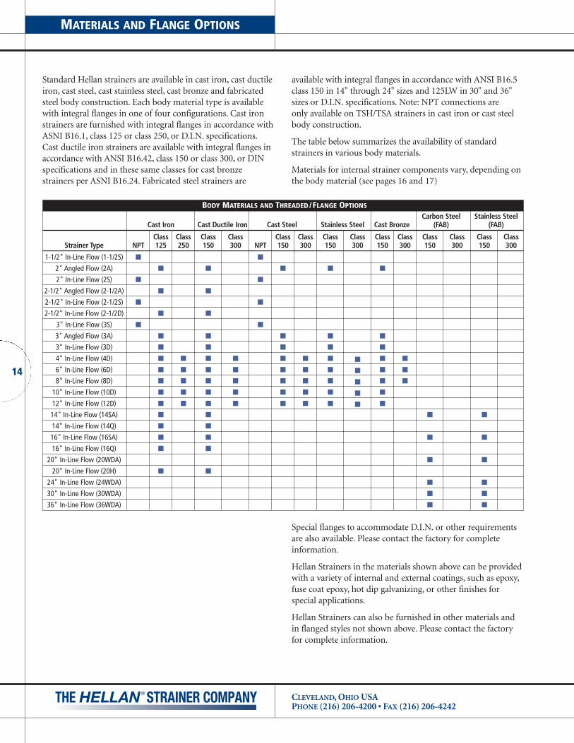
Standard Hellan strainers are available in cast iron, cast ductileiron, cast steel, cast stainless steel, cast bronze and fabricatedsteel body construction. Each body material type is availablewith integral flanges in one of four configurations. Cast ironstrainers are furnished with integral flanges in accordance withASNI B16.1, class 125 or class 250, or D.I.N. specifications.Cast ductile iron strainers are available with integral flanges inaccordance with ANSI B16.42, class 150 or class 300, or DINspecifications and in these same classes for cast bronze strainers per ASNI B16.24. Fabricated steel strainers are
BODY MATERIALS AND THREADED/FLANGE OPTIONS
Carbon Steel Stainless Steel Cast Iron Cast Ductile Iron Cast Steel Stainless Steel Cast Bronze (FAB) (FAB)
Class Class Class Class Class Class Class Class Class Class Class Class Class ClassStrainer Type NPT 125 250 150 300 NPT 150 300 150 300 150 300 150 300 150 300
1-1/2" In-Line Flow (1-1/2S) ■ ■
2" Angled Flow (2A) ■ ■ ■ ■ ■
2" In-Line Flow (2S) ■ ■
2-1/2" Angled Flow (2-1/2A) ■ ■
2-1/2" In-Line Flow (2-1/2S) ■ ■
2-1/2" In-Line Flow (2-1/2D) ■ ■
3" In-Line Flow (3S) ■ ■
3" Angled Flow (3A) ■ ■ ■ ■ ■
3" In-Line Flow (3D) ■ ■ ■ ■ ■
4" In-Line Flow (4D) ■ ■ ■ ■ ■ ■ ■ ■ ■ ■
6" In-Line Flow (6D) ■ ■ ■ ■ ■ ■ ■ ■ ■ ■
8" In-Line Flow (8D) ■ ■ ■ ■ ■ ■ ■ ■ ■ ■
10" In-Line Flow (10D) ■ ■ ■ ■ ■ ■ ■ ■ ■
12" In-Line Flow (12D) ■ ■ ■ ■ ■ ■ ■ ■ ■
14" In-Line Flow (14SA) ■ ■ ■ ■
14" In-Line Flow (14Q) ■ ■
16" In-Line Flow (16SA) ■ ■ ■ ■
16" In-Line Flow (16Q) ■ ■
20" In-Line Flow (20WDA) ■ ■
20" In-Line Flow (20H) ■ ■
24" In-Line Flow (24WDA) ■ ■
30" In-Line Flow (30WDA) ■ ■
36" In-Line Flow (36WDA) ■ ■
available with integral flanges in accordance with ANSI B16.5class 150 in 14" through 24" sizes and 125LW in 30" and 36"sizes or D.I.N. specifications. Note: NPT connections are only available on TSH/TSA strainers in cast iron or cast steelbody construction.
The table below summarizes the availability of standard strainers in various body materials.
Materials for internal strainer components vary, depending onthe body material (see pages 16 and 17)
Special flanges to accommodate D.I.N. or other requirementsare also available. Please contact the factory for complete information.
Hellan Strainers in the materials shown above can be providedwith a variety of internal and external coatings, such as epoxy,fuse coat epoxy, hot dip galvanizing, or other finishes for special applications.
Hellan Strainers can also be furnished in other materials andin flanged styles not shown above. Please contact the factoryfor complete information.
15
PRESSURE RATINGS AND FLOW RATES
CLEVELAND, OHIO USAPHONE (216) 206-4200 • FAX (216) 206-4242
PRESSURE RATINGS AND FLOW RATES
Cast iron Cast Ductile Iron Cast Steel Stainless Steel Cast Bronze Carbon Steel (FAB) Stainless Steel (FAB)
Strainer Flow Class Class Class Class Class Class Class Class Class Class Class Class Class ClassType Rate 125 250 150 300 150 300 150 300 150 300 150 300 150 300
GPM PSI PSI PSI PSI PSI PSI PSI PSI PSI PSI PSI PSI PSI PSIliter/min. bars bars bars bars bars bars bars bars bars bars bars bars bars bars
1-1/2" In-Line Flow (1-1/2S)95 175 250 285 275 220360 12.06 17.24 19.65 18.96 15.16
2" Angled Flow (2A)95 175 250 285 275 220360 12.06 17.24 19.65 18.96 15.16
2" In-Line Flow (2S)95 175 250 285 275 220360 12.06 17.24 19.65 18.96 15.16
2-1/2" In-Line Flow (2-1/2S)160 175 250 285 275 220606 12.06 17.24 19.65 18.96 15.16
2-1/2" In-Line Flow (2-1/2A)160 175 250 285 275 220606 12.06 17.24 19.65 18.96 15.16
2-1/2" In-Line Flow (2-1/2D)160 175 250 285 275 220606 12.06 17.24 19.65 18.96 15.16
3" In-Line Flow (3S)235 175 250 285 275 220880 12.06 17.24 19.65 18.96 15.16
3" Angled Flow (3A)235 175 250 285 275 220880 12.06 17.24 19.65 18.96 15.16
3" In-Line Flow (3D)235 175 250 285 275 220880 12.06 17.24 19.65 18.96 15.16
4" In-Line Flow (4D)360 175 350 250 450 285 450 275 450 220 4501363 12.06 24.13 17.24 31.02 19.65 31.02 18.96 31.02 15.16 31.02
6" In-Line Flow (6D)880 175 350 250 450 285 450 275 450 220 4503331 12.06 24.13 17.24 31.02 19.65 31.02 18.96 31.02 15.16 31.02
8" In-Line Flow (8D)1450 175 350 250 450 285 450 275 450 220 4505489 12.06 24.13 17.24 31.02 19.65 31.02 18.96 31.02 15.16 31.02
10" In-Line Flow (10D)2075 175 350 250 450 285 450 275 450 220 4507855 12.06 24.13 17.24 31.02 19.65 31.02 18.96 31.02 15.16 31.02
12" In-Line Flow (12D)2750 175 350 250 450 285 450 275 450 220 45010410 12.06 24.13 17.24 31.02 19.65 31.02 18.96 31.02 15.16 31.02
14" In-Line Flow (14SA)4100 75 250 75 7515520 5.17 17.24 5.17 5.17
14" In-Line Flow (14Q)4100 150 25015520 10.34 17.24
16" In-Line Flow (16SA)5300 75 250 75 7520063 5.17 17.24 5.17 5.17
16" In-Line Flow (16Q) 5300 150 25020063 10.34 17.24
20" In-Line Flow (20WDA)8250 75 7531230 5.17 5.17
20" In-Line Flow (20H) 8250 150 25031230 10.34 17.24
24" In-Line Flow (24WDA) 10650 75 7540315 5.17 5.17
30" In-Line Flow (30WDA)16650 75 7563027 5.17 5.17
36" In-Line Flow (36WDA)24000 75 7590850 5.17 5.17
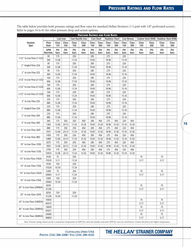
Note: Pressure ratings shown are for a maximum temperature of 100°F for steel and stainless steel and 150°F for cast iron and bronze. Contact the factory for higher temperature.
The table below provides both pressure ratings and flow rates for standard Hellan Strainers (1.5 psid with 1/8" perforated screen).Refer to pages 54 to 81 for other pressure drop and screen options.

COMPONENT MATERIALS
CLEVELAND, OHIO USAPHONE (216) 206-4200 • FAX (216) 206-4242
16
1 2 3 4 5 6 7 8
9 10 11 12 15
17 18 19
1613 14
20 232221 29
BODY COVERSHAFT
SCREEN
CLAMP BAR HANDWHEEL
END RING CENTER RING HUB WETTED
O-RING KEYS COLLAR
EXTERNALFASTENERS FASTENERSDEFLECTOR APRON
WASHER
1413
4 SCREEN CONFIGURATION14" & 16" SIZES ONLY
INSPECTION SCRAPERBLADE
MOTORIZEDDRIVE
MOTORIZEDVALVE
SWAGENIPPLE
SCREENPLATE
SHAFTPLATE
GASKET
23
22
AUTOMATIC CONFIGURATION ONLY
29
24
29
2121
GEARBOX HOUSINGADAPTER
~
103
1711
1518
2019
6
49
1
12
78
165
2
AUTOMATIC CONFIGURATION ONLY
The following drawings and chart list the standard componentmaterials of construction for Hellan Strainers of various body materials.
SINGLE SCREENCONFIGURATION

17
STRAINER MATERIAL TYPE
CLEVELAND, OHIO USAPHONE (216) 206-4200 • FAX (216) 206-4242
STRAINER MATERIAL TYPEComponents Cast Iron Cast Ductile Iron Cast Steel Cast Stainless Steel Cast Bronze
1 Body Cast Iron Ductile Iron Cast Steel Cast Stainless Steel BronzeASTM A278 Class 30 ASTM A395 ASTM A216 WCB ASTM A351 CF8M C-95800
2 Inspection Cover Cast iron Carbon Steel Carbon Steel Cast Stainless Steel BronzeASTM A278 Class 30 ASTM A29 1018 ASTM A29 1018 ASTM A351 CF8M C-95800
3 Scraper Blade Manganese Bronze Manganese Bronze Manganese Bronze Stainless Steel Cast MonelASTM B584 C86500 ASTM B584 C86500 ASTM B 584 C86500 ASTM A276 316 ASTM A494 Grade M35-1
4 Clamp Bar Red Brass Red Brass Red Brass Stainless Steel Cast MonelASTM B584 C83600 ASTM B584 C83600 ASTM B584 C83600 ASTM A276 316 ASTM A494 Grade M35-1
5 Screen Plate Cast Iron Cast Steel Cast Steel Cast Stainless Steel BronzeASTM A278 Class 30 ASTM A216 WCB ASTM A216 WCB ASTM A351 CF8M C-95800
6 Shaft Plate Carbon Steel Carbon Steel Carbon Steel Stainless Steel BronzeASTM A29 1018 ASTM A29 1018 ASTM A29 1018 ASTM A276 316 C-93800
7 Hand Wheel Cast Iron Cast iron Cast Iron Cast Iron – Zinc Plated BronzeASTM A48 Class 30 ASTM A48 Class 30 ASTM A48 Class 30 ASTM A48 Class 30 ASTM B61
8 Shaft Stainless Steel Stainless Steel Stainless Steel Stainless Steel Monel 400ASTM A276 316 ASTM A276 316 ASTM A276 316 ASTM A276 316 UNS N04400
9 Screen1 Stainless Steel Stainless Steel Stainless Steel Stainless Steel Monel 400ASTM A276 316 ASTM A276 316 ASTM A276 316 ASTM A276 316 UNS N04400
10 End Ring1 TIN Bronze TIN Bronze Stainless Steel Stainless Steel Monel 400ASTM B584 C93200 ASTM B584 C93200 ASTM A276 316 ASTM A276 316 UNS N04400
11 Center Ring1 Carbon Steel Carbon Steel Stainless Steel Stainless Steel Monel 400ASTM A29 1018 ASTM A29 1018 ASTM A276 316 ASTM A276 316 UNS N04400
12 Hub1 Cast Iron Cast iron Cast Stainless Steel Cast Stainless Steel Cast MonelASTM A278 Class 30 ASTM A278 Class 30 ASTM A351 CF8M ASTM A351 CF8M ASTM A494 Grade M35-1
13 Deflector2 Carbon Steel Carbon Steel Carbon Steel Stainless Steel Monel 400ASTM A29 1018 ASTM A29 1018 ASTM A29 1018 ASTM A276 316 UNS N04400
14 Apron2 Stainless Steel Stainless Steel Stainless Steel Stainless Steel Monel 400ASTM A276 316 ASTM A276 316 ASTM A276 316 ASTM A276 316 UNS N04400
15 Wetted Fasteners Stainless Steel Stainless Steel Stainless Steel Stainless Steel Monel 400ASTM A276 316 ASTM A276 316 ASTM A276 316 ASTM A276 316 UNS N04400
16 External Fasteners Medium Carbon Steel Medium Carbon Steel Medium Carbon Steel Stainless Steel Monel 400SAE Grade 2 SAE Grade 2 SAE Grade 2 ASTM A276 316 UNS N04400
17 O-Ring Nitrile (Buna N) Nitrile (Buna N) Nitrile (Buna N) Fluorocarbon (Viton) Viton18 Keys Stainless Steel Stainless Steel Stainless Steel Stainless Steel Monel 400
ASTM A276 316 ASTM A276 316 ASTM A276 316 ASTM A276 316 UNS N0440019 Collar Stainless Steel Stainless Steel Stainless Steel Stainless Steel Stainless Steel
ASTM A276 316 ASTM A276 316 ASTM A276 316 ASTM A276 316 ASTM A276 31620 Washer Sintered Bronze Sintered Bronze Sintered Bronze Sintered Bronze Sintered Bronze
ASTM B4384/B438-009 ASTM B4384/B438-009 ASTM B4384/B438-009 ASTM B4384/B438-009 ASTM B4384/B438-009 Grade 1Type Z Grade 1Type Z Grade 1Type Z Grade 1Type Z Grade 1Type Z
21 Motorized Drive6 Cast Iron Cast iron Cast Iron Cast Iron Bronze(Housing Adapter) ASTM A278 Class 30 ASTM A278 Class 30 ASTM A278 Class 30 ASTM A278 Class 30 C-93800
22 Motorized Valve6 Body Cast 316 Stainless Cast 316 Stainless Cast 316 Stainless Cast 316 Stainless BronzeASTM A276 316 ASTM A276 316 ASTM A276 316 ASTM A276 316 ASTM B61
Ball and Stem Stainless Steel Stainless Steel Stainless Steel Stainless Steel BronzeASTM A276 304 ASTM A276 304 ASTM A276 304 ASTM A276 304 ASTM B127
Packing and Seat PTFE PTFE PTFE PTFE PTFE23 Swage Nipple6 Carbon Steel Carbon Steel Carbon Steel Stainless Steel Monel 400
ASTM A234 ASTM A234 ASTM A234 T-304 ASTM B6124 Pressure Switch6 Stainless Steel Stainless Steel Stainless Steel Stainless Steel Stainless Steel
ASTM A278 304 ASTM A278 304 ASTM A278 304 ASTM A278 304 ASTM A278 304Diaphragm Stainless Steel Stainless Steel Stainless Steel Stainless Steel Stainless Steel
17-7 PH 17-7 PH 17-7 PH 17-7 PH 17-7 PHSeals Combination Nylon & Vitron Combination Nylon & Vitron Combination Nylon & Vitron Fluorocarbon (Viton) Fluorocarbon (Viton)
25 External Fittings6 316 Stainless Steel 316 Stainless Steel 316 Stainless Steel 316 Stainless Steel Monel 400 – UNS N0440026 External Tubing 316 Stainless Steel 316 Stainless Steel 316 Stainless Steel 316 Stainless Steel Monel 400 – UNS N0440027 Lubricant3 Molykote G-n5 Molykote G-n5 Molykote G-n5 Molykote G-n5 Molykote G-n5
Mo-S2 & Mineral Oil Mo-S2 & Mineral Oil Mo-S2 & Mineral Oil Mo-S2 & Mineral Oil Mo-S2 & Mineral Oil28 External Paint8 Machinery Gray Alkyd enamel Machinery Gray Alkyd enamel Machinery Gray Alkyd Enamel Not Applicable Not Applicable29 Gaskets Vegetable Fiber Vegetable Fiber Vegetable Fiber Vegetable Fiber Blue GuardNotes: 1) Comprise a welded assembly, not available separately.2) Deflector and apron are only in 14", 16" and 20" strainers.3) Lubricant is applied to threaded fasteners, thrust washers and press fit parts.4) Stainless strainers also have a shaft bushing made from RULON J. RULON
is a trademark of Dixon, Division of Furon.5) MOLYKOTE is a trademark of Dow Chemical Company.
6) Motorized components are used only on automatic strainers.7) Strainers in sizes of 2" an 2-1/2" with single screens and 2-1/2" and 3" with dual screens
have scraper blades integral with the body and do not use clamp bars.8) Other coatings, such as epoxy, fuse coat epoxy, hot dip galvanizing and other special
coatings are available upon request.9) Body and component materials, other than those listed above, are available upon request.

AUTOMATIC STRAINERS
CLEVELAND, OHIO USAPHONE (216) 206-4200 • FAX (216) 206-4242
18
Automatic Hellan Strainers are used whenever automaticself-cleaning of the strainer is required or advantageous.Under normal operating conditions, these units can performa complete cleaning cycle in just 15 seconds. This meansthat only a small amount of fluid is needed to flush solidsfrom the strainer and it assures a more uniform flow ofstrained fluid.
OPTIMIZED CLEANING
Automatic cleaning allows you to optimize the cleaning cyclewhile you minimize maintenance labor costs. It provides thebest cleaning action by simultaneously rotating the cleaningscreen and operating the discharge valve which creates turbulence and enhances cleaning.
A balance must also be struck between the fluid discharge during a cleaning cycle and pumping efficiency across aclogged strainer. Clean too soon and you waste some fluid inthe discharge. Clean too late and you waste power pumpingacross a clogged system.
The Hellan Automatic Strainer enables you to tailor the cleaning cycle to your specific needs. You set a timer to cleanwhenever you choose.
AUTOMATIC STRAINER SIZES
Automatic strainers, in cast body construction, are available in 1-1/2" through 20" pipe sizes. The 1.5"– 3" strainers (singlescreen) are furnished with one 1-1/2" discharge valve; the 4"through 12" (dual screens) are furnished with one 2" dis-charge valve; the 14" and 16" (4 screens) and 20" (6 screens)are furnished with two 2" discharge valves to obtain the optimum flushing action.
Automatic strainers, in fabricated body construction, areavailable in 14" through 36" pipe sizes with two screens. The14" and 16" are furnished with two 2" discharge valves; the 20"and 24" are furnished with two 3" discharge valves; the 30"and 36" are furnished with two 4" discharge valves to obtainthe optimum flushing action.
ELECTRICAL COMPONENTS
The basic components of the self-cleaning strainer are the differential pressure switch, the screen drive, the actuated discharge valve and the control panel.
The drive replaces the handwheel and rotates each screen at approximately 17 RPM.
An actuated ball valve opens and closes the waste dischargeport. To sense the clogging of the screen, a differential pressureswitch monitors pressure drop across the strainer.
The control panel synchronizes the screen drives and the discharge valve to achieve the optimum cleaning cycle.This cleans the screens without excessive discharge of the system fluid.
IEC STANDARDS
Motors are available to meet or exceed the following IEC standards: 1P21, 22, 23, 44, 54, 55, 56, 57, 65, 67 and 68.
SELECTION OF AUTOMATIC STRAINER MODEL
To select an automatic strainer and specify a model number,see the information on selecting and specifying a strainermodel on pages 82-83.
EASY CONVERSION TO AUTOMATIC OPERATION
The strainer can be converted from manual to automatic operation in three easy steps.
1
2
3

19
AUTOMATIC STRAINER CONTROLS
CLEVELAND, OHIO USAPHONE (216) 206-4200 • FAX (216) 206-4242
HAND/OFF/AUTOMATIC
The rotary H-O-A selector switch allows for three modes ofoperation. In the “Hand” position, the screen drives and flushvalve will be actuated until the switch is returned to off.
In the “OFF” position, the self-cleaning cycle does not function.
In the “AUTOMATIC” mode, there are three ways to initiate a cleaning cycle:
1. Differential pressure switch. As the screen becomes clogged,the pressure drop will increase. At a preset point, a cleaningcycle will start.
2. Internal timer. An automatic interval between cleaningcycles can be set from 1 minute to 24 hours.
3. Manual start. A momentary push-button on the controlpanel will start a cleaning cycle.
SYSTEM SAFETY MONITORS
The control panel is a constant indicator of the status of yoursystem. For example, a panel light illuminates when power isapplied to the strainer motor relay.
If the strainer basket is not thoroughly cleaning during the normal cleaning cycle, the pressure drop continues to increase,causing the high pressure light to illuminate.
The alarm is self-resetting when the differential pressure dropfalls below the set point.
REMOTE OPERATIONS
Manual Cycle StartYou may attach a normally open, momentary push-button tothe control panel terminal strip. The H-O-A switch must be inthe AUTOMATIC position for the cycle to start.
High Pressure Alarm OptionA set of contacts controlled by the high pressure alarm light isavailable as an option.
Hand/Off/AutomaticIf you require these functions at a remote location, the controlpanel H-O-A switch must be disconnected.
IEC STANDARDS
NEMA 12 controls panels meet or exceed IEC IP10 through IP65.
NEMA 4 control panels meet or exceed IEC IP66.NEMA 4X control panels meet or exceed IEC 529 IP66.Control panels are also available with IEC components.
SELECTION OF AUTOMATIC STRAINER CONTROL
Strainer controls are ordered separately from the strainer. Theselection of the control is based on both the number of motors(i.e., “AA”, “SA” & “TSA” types have one motor; “DA” & “WDA”types have two motors; “QA” types have four motors and “HH”types have six motors) and their voltage. The voltage to thecontrol panel must be the same as the motor voltage. To selecta control panel and specify a model number, see the informa-tion on selecting and specifying a control panel model onpages 82-83.
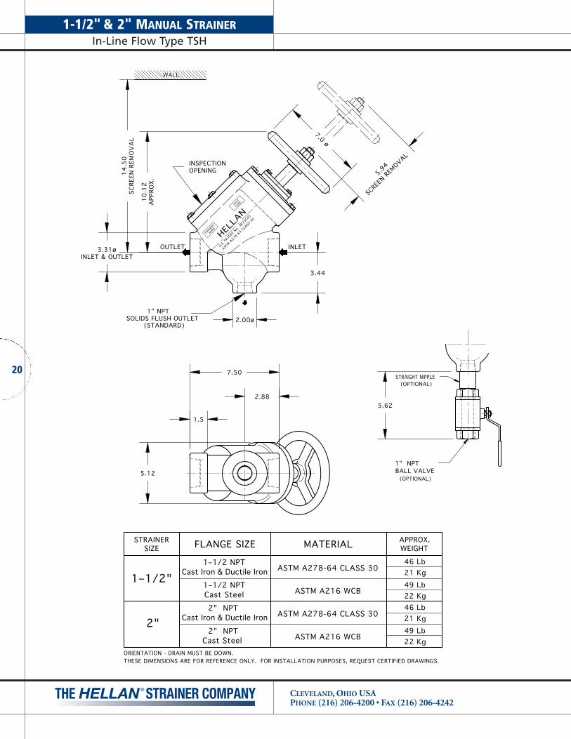
1-1/2" & 2" MANUAL STRAINERIn-Line Flow Type TSH
CLEVELAND, OHIO USAPHONE (216) 206-4200 • FAX (216) 206-4242
20
MATERIALFLANGE SIZE
Cast Iron & Ductile Iron
Cast Iron & Ductile Iron
1–1/2 NPT
Cast Steel1–1/2 NPT
ASTM A278-64 CLASS 30 21 Kg
WEIGHT
46 Lb
49 Lb22 Kg
APPROX.STRAINERSIZE
1–1/2"
2"2" NPT
Cast Steel
2" NPT
22 Kg49 Lb
46 Lb21 Kg
(OPTIONAL)BALL VALVE1" NPT
STRAIGHT NIPPLE(OPTIONAL)
(STANDARD)
HELLA
N
U.S. PA
TENT
No. RE
35560
ASTM A
278-64 C
LASS
30
MARKFO
UNDRY
HEAT
CODE
ASTM A278-64 CLASS 30
ASTM A216 WCB
ASTM A216 WCB
ORIENTATION - DRAIN MUST BE DOWN.
7.50
1.5
2.88
5.12
3.31øINLET & OUTLET
2.00ø
10
.12
APP
ROX.
14
.50
SCRE
EN R
EMO
VA
L7.0 ø
WALL
INSPECTIONOPENING
5.62
SOLIDS FLUSH OUTLET1" NPT
3.44
THESE DIMENSIONS ARE FOR REFERENCE ONLY. FOR INSTALLATION PURPOSES, REQUEST CERTIFIED DRAWINGS.
5.94
SCRE
EN R
EMOVAL
INLETOUTLET

(OPTIONAL)BALL VALVE1–1/2" NPT
STRAIGHT NIPPLE(OPTIONAL)
(STANDARD)
025TS14-0
0RS
CODE
HEAT
FOUNDRY
MARK
HELLA
N
U.S. PA
TENT
No. RE
35560
ASTM A
278-64 C
LASS
30
9.75
2.25
3.75
5.12ø
4.62øINLET & OUTLET
2.75ø
11
.63
APP
ROX.
17
.25
SCRE
EN R
EMO
VA
L
7.0 ø
WALL
INSPECTIONOPENING
6.25
SOLIDS FLUSH OUTLET1–1/2" NPT
4.12
7.78
SCRE
EN R
EMOVAL
INLETOUTLET
MATERIALFLANGE SIZE
Cast Iron & Ductile Iron
Cast Iron & Ductile Iron
2–1/2 NPT
Cast Steel2–1/2 NPT
ASTM A278-64 CLASS 30 38 Kg
WEIGHT
84 Lb
89 Lb40 Kg
APPROX.STRAINERSIZE
2–1/2"
3"3" NPT
Cast Steel
3" NPT
40 Kg89 Lb
84 Lb38 KgASTM A278-64 CLASS 30
ASTM A216 WCB
ASTM A216 WCB
ORIENTATION - DRAIN MUST BE DOWN.THESE DIMENSIONS ARE FOR REFERENCE ONLY. FOR INSTALLATION PURPOSES, REQUEST CERTIFIED DRAWINGS.
21
2-1/2" & 3" MANUAL STRAINERIn-Line Flow Type TSH
CLEVELAND, OHIO USAPHONE (216) 206-4200 • FAX (216) 206-4242

2" MANUAL STRAINERAngled Flow Type AH
CLEVELAND, OHIO USAPHONE (216) 206-4200 • FAX (216) 206-4242
22
TOP & SIDEFLANGE
1-1/4" NPTBALL VALVE
(OPTIONAL)
(STANDARD)
(OPTIONAL)STRAIGHT NIPPLE
FOR ANSI FLANGECLASS 150
WA
LL
FLANGE DRILLING (NUMBER AND SIZE OF HOLES AND BOLT CIRCLE)IS IN ACCORDANCE WITH D.I.N. STANDARDS.
ALL OTHER APPLICABLE DIMENSIONS ARE IN ACCORDANCE WITH ANSI STANDARDS ABOVE.
ANSI class 150
50 ND 10DIN 2501
Cast Steel4.56119
10.56271MM
INCH .7519 26 Kg
58 Lb
ANSI class 125Cast Iron & Ductile Iron
B
4.50
A
10.50INCH114267MM
C
.6918
55 Lb
WEIGHTAPPROX.
25 Kg
FLANGE SIZE
THESE DIMENSIONS ARE FOR REFERENCE ONLY. FOR INSTALLATION PURPOSES, REQUEST CERTIFIED DRAWINGS.
2.004.75
.75 DIA (19mm)
OUTLET
SOLIDS FLUSH OUTLET1–1/4" NPT
B
A
6.00
C
7.00
B7.50
13.50 (MINIMUM CLEARANCEFOR SCREEN REMOVAL)
CFLANGE
INLETFLANGE
(51mm)(121mm)
4 HOLES
(191mm)
(152mm)
(178mm)
(343mm)
(152mm)6.00
5.62
(105mm)4.12
(1.5mm).06

FLANGE DRILLING (NUMBER AND SIZE OF HOLES AND BOLT CIRCLE)IS IN ACCORDANCE WITH D.I.N. STANDARDS.
ALL OTHER APPLICABLE DIMENSIONS ARE IN ACCORDANCE WITH ANSI STANDARDS ABOVE.
ANSI class 150
65 ND 10DIN 2501
Cast Steel5.19130
12.19310MM
INCH .8822 34 Kg
74 Lb
B
5.00
A
12.00INCH127305MM
C
.6918
70 Lb
WEIGHTAPPROX.
32 Kg
STRAIGHT NIPPLE(OPTIONAL)
(OPTIONAL)BALL VALVE1–1/2" NPT
(STANDARD)
CLASS 150FOR ANSI FLANGE
FLANGETOP & SIDE
WA
LL
FLANGE SIZE
2.505.50
.75 DIA (19mm)
OUTLET
B
A
7.00
C
7.00
B8.25
15.38 (MINIMUM CLEARANCEFOR SCREEN REMOVAL)
CFLANGE
INLETFLANGE
(64mm)(140mm)
4 HOLES
(210mm)
(178mm)
(178mm)
(391mm)
(178mm)7.00
6.25
SOLIDS FLUSH OUTLET1–1/2" NPT
.06(1.5mm)
4.12(105mm)
THESE DIMENSIONS ARE FOR REFERENCE ONLY. FOR INSTALLATION PURPOSES, REQUEST CERTIFIED DRAWINGS.
ANSI class 125Cast Iron & Ductile Iron
23
2-1/2" MANUAL STRAINERAngled Flow Type AH
CLEVELAND, OHIO USAPHONE (216) 206-4200 • FAX (216) 206-4242
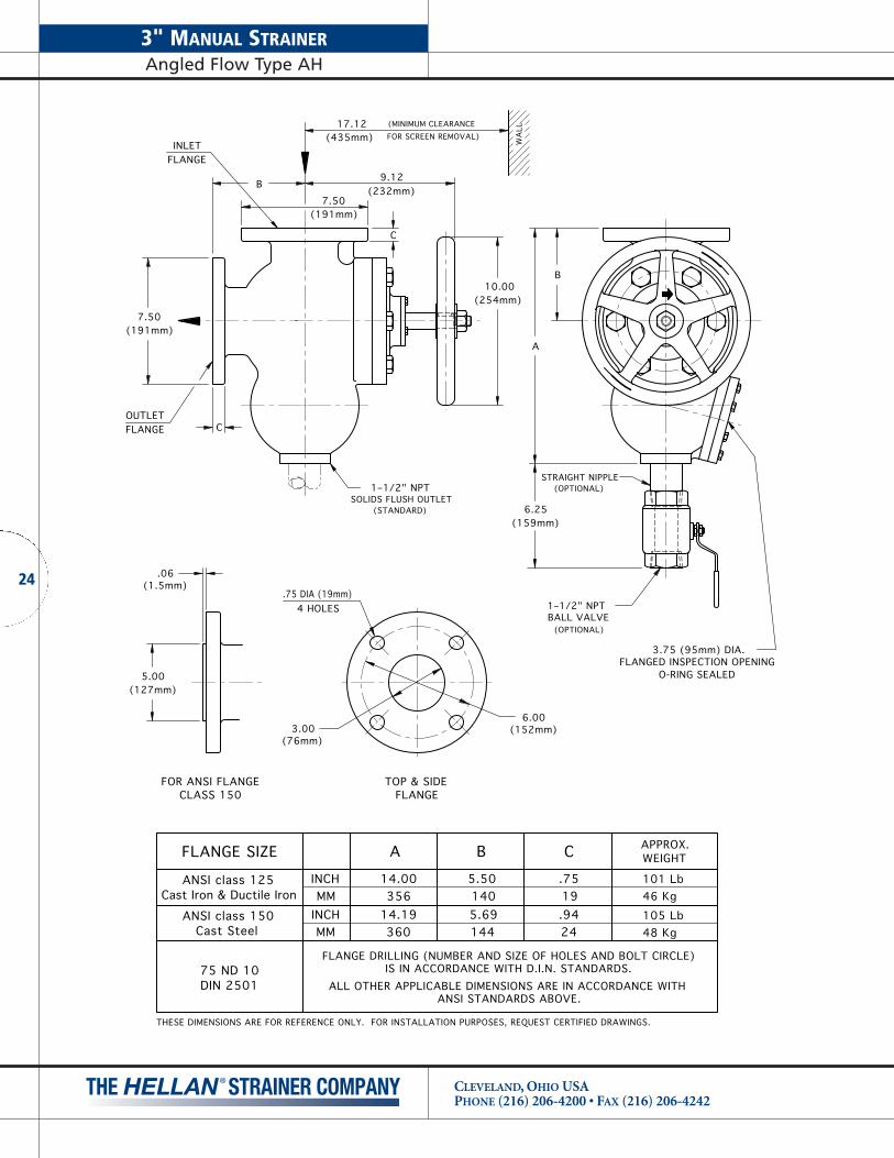
3" MANUAL STRAINERAngled Flow Type AH
CLEVELAND, OHIO USAPHONE (216) 206-4200 • FAX (216) 206-4242
24
1–1/2" NPTBALL VALVE
(OPTIONAL)
(OPTIONAL)STRAIGHT NIPPLE
(STANDARD)
CLASS 150FOR ANSI FLANGE TOP & SIDE
FLANGE
WA
LL
3.006.00
.75 DIA (19mm)
OUTLET
B
A
7.50
C
10.00
B9.12
17.12 (MINIMUM CLEARANCEFOR SCREEN REMOVAL)
CFLANGE
INLETFLANGE
(76mm)(152mm)
4 HOLES
(232mm)
(191mm)
(254mm)
(435mm)
(191mm)7.50
6.25
1–1/2" NPTSOLIDS FLUSH OUTLET
O-RING SEALEDFLANGED INSPECTION OPENING
3.75 (95mm) DIA.
(159mm)
(1.5mm)
5.00(127mm)
.06
ALL OTHER APPLICABLE DIMENSIONS ARE IN ACCORDANCE WITH ANSI STANDARDS ABOVE.
APPROX.WEIGHT
101 Lb
105 Lb1445.69
5.50
FLANGE DRILLING (NUMBER AND SIZE OF HOLES AND BOLT CIRCLE)IS IN ACCORDANCE WITH D.I.N. STANDARDS.
ANSI class 150 INCH 14.19MMCast Steel
DIN 250175 ND 10
360
INCHMM
ANSI class 125Cast Iron & Ductile Iron 356
14.00
A
140
B
.9424 48 Kg
19.75
C
46 Kg
FLANGE SIZE
THESE DIMENSIONS ARE FOR REFERENCE ONLY. FOR INSTALLATION PURPOSES, REQUEST CERTIFIED DRAWINGS.

WA
LL
15.37(390mm)
(MINIMUM SCREENACCESS CLEARANCE)
10.88(276mm)
7.00(178mm)
30°
B
D
21.76(552mm)
3.50(89mm)
5.50
TOP & BOTTOM FLANGES
(140mm) (63.5mm)2.50
4 HOLES.75 DIA. (19mm)
FOR ANSI FLANGE CLASS 150
7.00(178mm)
.06 (1.5mm)C
D
(68mm)2.69
5.70(145mm)
7.00(178mm)
12.00(305mm)
(OPTIONAL)
1–1/2" NPTBALL VALVE
(248mm)9.75
C
(STANDARD)
1–1/2" NPTSOLIDS FLUSH OUTLET
STRAIGHT NIPPLE(OPTIONAL)
ALL OTHER APPLICABLE DIMENSIONS ARE IN ACCORDANCE WITH ANSI STANDARDS ABOVE.
APPROX.WEIGHT
100 Lb
105 Lb1224.81
4.69
FLANGE DRILLING (NUMBER AND SIZE OF HOLES AND BOLT CIRCLE)IS IN ACCORDANCE WITH D.I.N. STANDARDS.
ANSI class 150 INCH 3.62MMCast Steel
DIN 250165 ND 10
92
INCHMM
ANSI class 125Cast Iron & Ductile Iron 89
3.50
B
119
C
.8822 48 Kg
19.75
D
45 Kg
4.12(105mm)
FLANGE SIZE
THESE DIMENSIONS ARE FOR REFERENCE ONLY. FOR INSTALLATION PURPOSES, REQUEST CERTIFIED DRAWINGS.
25
2-1/2" MANUAL STRAINERIn-Line Flow Type DH
CLEVELAND, OHIO USAPHONE (216) 206-4200 • FAX (216) 206-4242
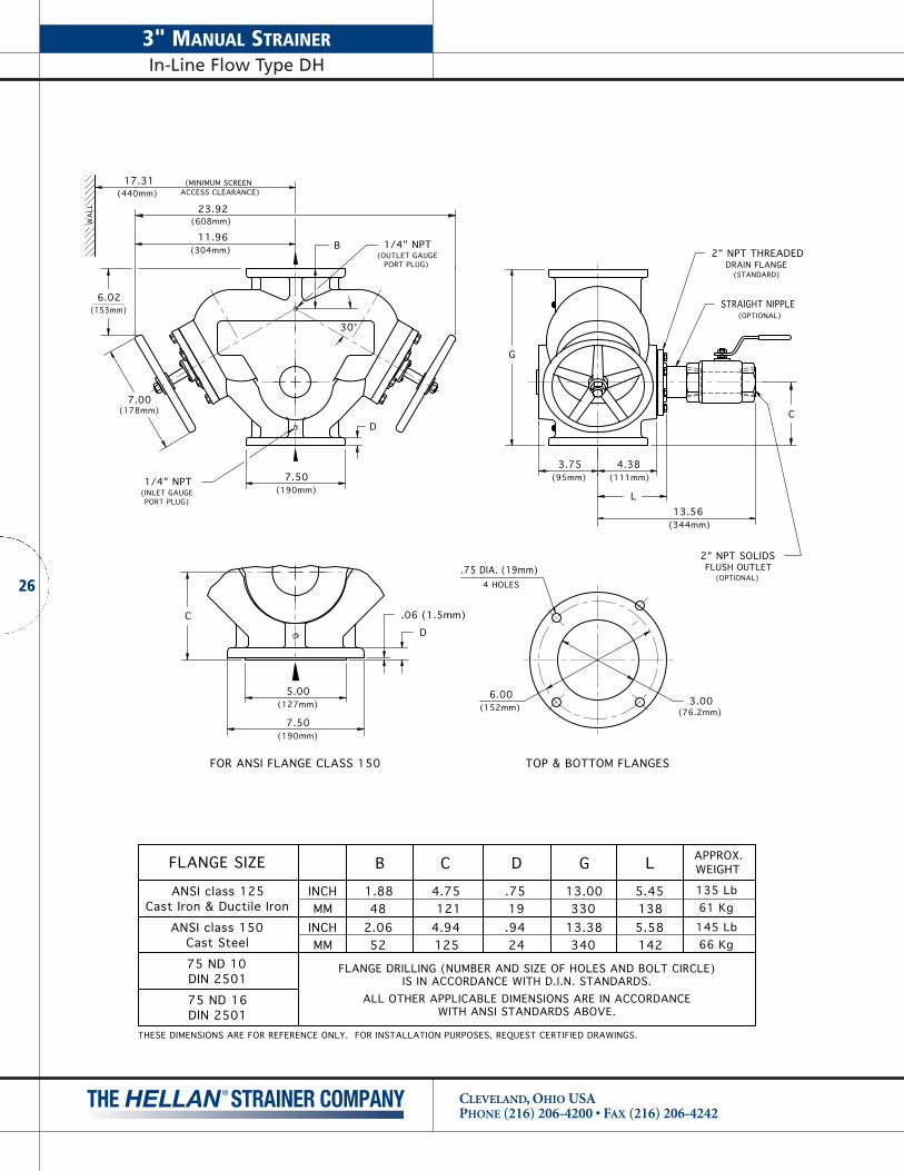
3" MANUAL STRAINERIn-Line Flow Type DH
CLEVELAND, OHIO USAPHONE (216) 206-4200 • FAX (216) 206-4242
26
WA
LL
17.31(440mm)
(MINIMUM SCREENACCESS CLEARANCE)
11.96(304mm)
6.02
7.00(178mm)
30°
B
D
4.38
G
1/4" NPT(INLET GAUGEPORT PLUG)
PORT PLUG)(OUTLET GAUGE
1/4" NPT
23.92(608mm)
L
L
5.451385.58142
ANSI class 125Cast Iron & Ductile Iron
ANSI class 150Cast Steel
INCHMM
INCHMM 52
2.0648
1.88
B
1254.94121
4.75
C
24.9419.75
D
34013.38330
13.00
GFLANGE SIZE
3.75(95mm)
APPROX.WEIGHT
135 Lb61 Kg145 Lb66 Kg
DIN 250175 ND 16
DIN 250175 ND 10
FOR ANSI FLANGE CLASS 150
5.00
.06 (1.5mm)CD
7.50
6.00
(76.2mm)3.00
TOP & BOTTOM FLANGES
13.56
C
(111mm)
(344mm)
(STANDARD)
2" NPT THREADEDDRAIN FLANGE
(OPTIONAL)
2" NPT SOLIDSFLUSH OUTLET
STRAIGHT NIPPLE(OPTIONAL)
(153mm)
(190mm)
(127mm) (152mm)
4 HOLES.75 DIA. (19mm)
FLANGE DRILLING (NUMBER AND SIZE OF HOLES AND BOLT CIRCLE)IS IN ACCORDANCE WITH D.I.N. STANDARDS.
ALL OTHER APPLICABLE DIMENSIONS ARE IN ACCORDANCEWITH ANSI STANDARDS ABOVE.
(190mm)7.50
THESE DIMENSIONS ARE FOR REFERENCE ONLY. FOR INSTALLATION PURPOSES, REQUEST CERTIFIED DRAWINGS.
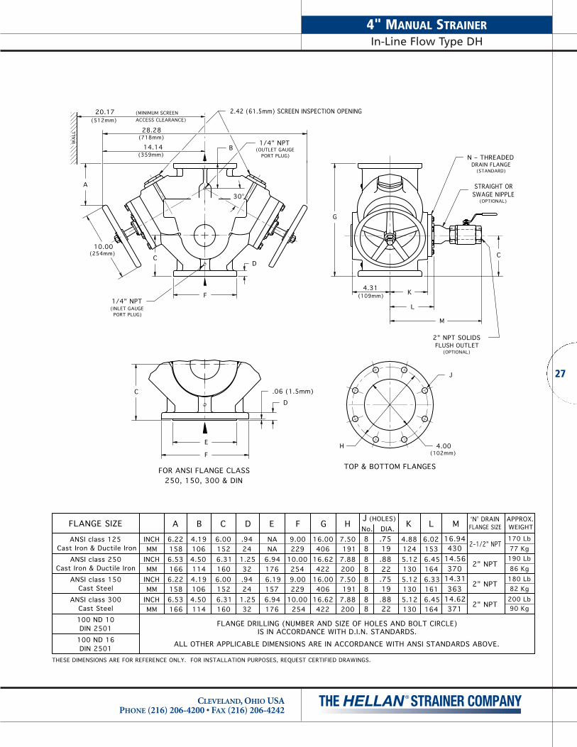
2.42 (61.5mm) SCREEN INSPECTION OPENING
WA
LL
20.17(512mm)
(MINIMUM SCREENACCESS CLEARANCE)
14.14(359mm)
A
10.00(254mm)
30°
B
D
F K
G
1/4" NPT(INLET GAUGE
PORT PLUG)
PORT PLUG)(OUTLET GAUGE1/4" NPT
C
28.28(718mm)
L
L
6.021536.451646.331616.4516422
.8819.7522.8819.75
88888888
37114.62363
14.31370
14.56430
16.94
A
ANSI class 125Cast Iron & Ductile Iron
ANSI class 250Cast Iron & Ductile Iron
ANSI class 150Cast Steel
ANSI class 300Cast Steel
INCHMM
INCHMM
INCHMM
INCHMM
6.221586.531666.221586.53166 114
4.501064.191144.501064.19
B
1606.311526.001606.311526.00
C
321.2524.9432
1.2524.94
D
1766.941576.191766.94NANA
E
25410.002299.00254
10.002299.00
F
42216.62406
16.00422
16.62406
16.00
G
2007.88191
7.502007.88191
7.50
HJNo. DIA. M(HOLES)
4.31
1305.121305.121305.121244.88
K
(109mm)
APPROX.WEIGHT
170 Lb77 Kg190 Lb86 Kg180 Lb82 Kg200 Lb90 Kg
100 ND 10DIN 2501
100 ND 16DIN 2501
J
250, 150, 300 & DINFOR ANSI FLANGE CLASS
E
.06 (1.5mm)C
D
FH
(102mm)4.00
TOP & BOTTOM FLANGES
M
FLUSH OUTLET2" NPT SOLIDS
STRAIGHT OR
FLANGE SIZEʻNʼ DRAIN
2–1/2" NPT
2" NPT
2" NPT
2" NPT
ALL OTHER APPLICABLE DIMENSIONS ARE IN ACCORDANCE WITH ANSI STANDARDS ABOVE.
FLANGE DRILLING (NUMBER AND SIZE OF HOLES AND BOLT CIRCLE)IS IN ACCORDANCE WITH D.I.N. STANDARDS.
C
(OPTIONAL)
(OPTIONAL)
SWAGE NIPPLE
DRAIN FLANGEN – THREADED
(STANDARD)
THESE DIMENSIONS ARE FOR REFERENCE ONLY. FOR INSTALLATION PURPOSES, REQUEST CERTIFIED DRAWINGS.
FLANGE SIZE
27
4" MANUAL STRAINERIn-Line Flow Type DH
CLEVELAND, OHIO USAPHONE (216) 206-4200 • FAX (216) 206-4242

6" MANUAL STRAINERIn-Line Flow Type DH
CLEVELAND, OHIO USAPHONE (216) 206-4200 • FAX (216) 206-4242
28
3.25 (83mm) SCREEN INSPECTION OPENING
WA
LL
26.05(662mm)
(MINIMUM SCREENACCESS CLEARANCE)
17.66(448mm)
A
10.00(254mm)
30°
B
D
FK
G
1/4" NPT(INLET GAUGE
PORT PLUG)
PORT PLUG)(OUTLET GAUGE
1/4" NPT
35.32(896mm)
L
L
7.641948.222097.952028.0920522
.8822.8822.8822.88
121288
121288
A
ANSI class 125Cast Iron & Ductile Iron
ANSI class 250Cast Iron & Ductile Iron
ANSI class 150Cast Steel
ANSI class 300Cast Steel
INCHMM
INCHMM
INCHMM
INCHMM
8.952279.392388.952279.39238 135
5.311244.881355.311244.88
B
1927.561817.121927.561817.12
C
371.4425
1.0037
1.4425
1.00
D
2168.502168.502469.69NANA
E
31812.50279
11.00318
12.50279
11.00
F
53020.88508
20.00530
20.88508
20.00
G
27010.62241
9.50270
10.62241
9.50
HJNo. DIA.
(HOLES)
P
1526.00
1556.121556.12
P
1676.561676.561676.561646.44
K
O-RING SEALED
APPROX.WEIGHT400 Lb182 Kg425 Lb193 Kg430 Lb195 Kg455 Lb207 Kg
150 ND 10DIN 2501
150 ND 16DIN 2501
J
250, 150, 300 & DINFOR ANSI FLANGE CLASS
E
.06 (1.5mm)C
D
F H(152mm)
6.00
TOP & BOTTOM FLANGES
C
6.12155
M
2" NPT SOLIDS
(OPTIONAL)FLUSH OUTLET
(STANDARD)
(OPTIONAL)
N – THREADEDDRAIN FLANGE
SWAGE NIPPLE
N DRAIN
3" NPT
FLANGE SIZEM
19.50495
19.62498
48419.06
48319.00 2–1/2" NPT
3" NPT
FLANGE DRILLING (NUMBER AND SIZE OF HOLES AND BOLT CIRCLE)IS IN ACCORDANCE WITH D.I.N. STANDARDS.
ALL OTHER APPLICABLE DIMENSIONS ARE IN ACCORDANCE WITH ANSI STANDARDS ABOVE.
2–1/2" NPT
FLANGE SIZE
THESE DIMENSIONS ARE FOR REFERENCE ONLY. FOR INSTALLATION PURPOSES, REQUEST CERTIFIED DRAWINGS.
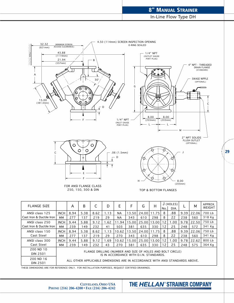
4.50 (114mm) SCREEN INSPECTION OPENING
WA
LL
32.32(821mm)
(MINIMUM SCREENACCESS CLEARANCE)
21.94(557mm)
A
15.00(381.0mm)
30°
B
D
F8.00
(203mm)8.00
(203mm)
G
43.88(1114mm)
L L
L
9.392389.782489.392389.7824825
1.0022.8825
1.0022.88
121288
121288
A
ANSI class 125Cast Iron & Ductile Iron
ANSI class 250Cast Iron & Ductile Iron
ANSI class 150Cast Steel
ANSI class 300Cast Steel
INCHMM
INCHMM
INCHMM
INCHMM
8.942779.442398.942779.44239 149
5.881375.381495.881375.38
B
2329.122198.622329.122198.62
C
431.6929
1.1341
1.6229
1.13
D
27010.62270
10.62503
11.94NANA
E
38115.00343
13.50381
15.00343
13.50
F
63525.00610
24.00635
25.00610
24.00
G
33013.00298
11.75330
13.00298
11.75
H JNo. DIA.
(HOLES)
O-RING SEALED
APPROX.WEIGHT
700 Lb318 Kg750 Lb341 Kg750 Lb341 Kg
800 Lb364 Kg
200 ND 10DIN 2501
200 ND 16DIN 2501
J
250, 150, 300 & DINFOR ANSI FLANGE CLASS
E
.06 (1.5mm)C
D
FH
(203mm)8.00
TOP & BOTTOM FLANGES
C
M
(OUTLET GAUGEPORT PLUG)
1/4" NPT
PORT PLUG)(INLET GAUGE1/4" NPT
DRAIN FLANGE4" NPT - THREADED
(STANDARD)
(OPTIONAL)SWAGE NIPPLE
FLUSH OUTLET(OPTIONAL)
2" NPT SOLIDS
M
22.06
22.50
22.06
22.62575
560
572
560
ALL OTHER APPLICABLE DIMENSIONS ARE IN ACCORDANCE WITH ANSI STANDARDS ABOVE.
FLANGE DRILLING (NUMBER AND SIZE OF HOLES AND BOLT CIRCLE)IS IN ACCORDANCE WITH D.I.N. STANDARDS.
THESE DIMENSIONS ARE FOR REFERENCE ONLY. FOR INSTALLATION PURPOSES, REQUEST CERTIFIED DRAWINGS.
FLANGE SIZE
29
8" MANUAL STRAINERIn-Line Flow Type DH
CLEVELAND, OHIO USAPHONE (216) 206-4200 • FAX (216) 206-4242
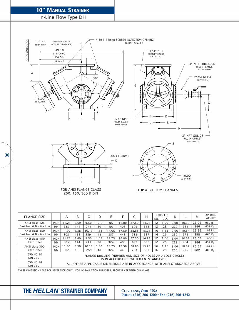
10" MANUAL STRAINERIn-Line Flow Type DH
CLEVELAND, OHIO USAPHONE (216) 206-4200 • FAX (216) 206-4242
30
4.50 (114mm) SCREEN INSPECTION OPENING
WA
LL
36.77(934mm)
(MINIMUM SCREENACCESS CLEARANCE)
24.59(625mm)
A
15.00(381.0mm)
30°
B
D
FK K
G
49.18(1250mm)
L L
L
10.39264
10.8427529
1.1225
1.00
16161212
60223.69586
23.06598
23.56586
23.06
A
ANSI class 125Cast Iron & Ductile Iron
ANSI class 250Cast Iron & Ductile Iron
ANSI class 150Cast Steel
ANSI class 300Cast Steel
INCHMM
INCHMM
INCHMM
INCHMM
11.21285
11.90302 162
6.381445.69
B
25910.192419.50
C
481.8830
1.19
D
35714.06
NANA
E
44517.50406
16.00
F
73328.88699
27.50
G
38715.25362
14.25
H JNo. DIA. M(HOLES)
O-RING SEALED
APPROX.WEIGHT
950 lb432 Kg1025 lb466 Kg1000 lb454 Kg
1075 lb488 Kg
250 ND 10DIN 2501
250 ND 16DIN 2501
250, 150, 300 & DINFOR ANSI FLANGE CLASS
E
.06 (1.5mm)CD
F(254mm)10.00
44517.50406
16.00
10.19
9.50
30211.90
1626.38
259
28511.21
1445.69
241
481.88
32412.75
301.19 12.75
32415.25
73328.88 10.84
387 275
14.25699
27.50 10.39362 264
291.12
1616
1.001212
25
K
9.002299.062309.002299.06230
M
1/4" NPT
PORT PLUG)(OUTLET GAUGE
PORT PLUG)
1/4" NPT(INLET GAUGE
C
4" NPT THREADEDDRAIN FLANGE
(STANDARD)
SWAGE NIPPLE(OPTIONAL)
(OPTIONAL)
2" NPT SOLIDSFLUSH OUTLET
ALL OTHER APPLICABLE DIMENSIONS ARE IN ACCORDANCE WITH ANSI STANDARDS ABOVE.
FLANGE DRILLING (NUMBER AND SIZE OF HOLES AND BOLT CIRCLE)IS IN ACCORDANCE WITH D.I.N. STANDARDS.
TOP & BOTTOM FLANGES
H
J
THESE DIMENSIONS ARE FOR REFERENCE ONLY. FOR INSTALLATION PURPOSES, REQUEST CERTIFIED DRAWINGS.
FLANGE SIZE

4.50 (114mm) SCREEN INSPECTION OPENING
WA
LL
41.32(1050mm)
(MINIMUM SCREENACCESS CLEARANCE)
27.19(691mm)
A
15.00(381.0mm)
30°
B
D
F10.00
(254mm)10.00
(254mm)
G
C
54.38(1382mm)
L L
L
11.39289
11.78299
11.39289
11.7829932
1.2525
1.0032
1.2525
1.00
1616121216161212
A
ANSI class 125Cast Iron & Ductile Iron
ANSI class 250Cast Iron & Ductile Iron
ANSI class 150Cast Steel
ANSI class 300Cast Steel
INCHMM
INCHMM
INCHMM
INCHMM
12.71323
13.46342
12.71323
13.46342 175
6.881566.121756.881566.12
B
29211.50273
10.75292
11.50273
10.75
C
512.0032
1.2551
2.0032
1.25
D
38115.00381
15.00417
16.44NANA
E
52120.50
48319.00
52120.50
48319.00
F
84433.25806
31.75844
33.25806
31.75
G
45117.75432
17.00451
17.75432
17.00
H JNo. DIA.
(HOLES)
O-RING SEALED
APPROX.WEIGHT
1350 Lb614 Kg1450 Lb659 Kg1450 Lb659 Kg
1550 Lb704 Kg
300 ND 10DIN 2501
300 ND 16DIN 2501
J
250, 150, 300 & DINFOR ANSI FLANGE CLASS
E
.06 (1.5mm)CD
F H(305mm)12.00
TOP & BOTTOM FLANGES
M
DRAIN FLANGE4" NPT THREADED
SWAGE NIPPLE
(STANDARD)
(OPTIONAL)
FLUSH OUTLET2" NPT SOLIDS
(OPTIONAL)
61124.62625
M
24.50611
24.06
24.06622
ALL OTHER APPLICABLE DIMENSIONS ARE IN ACCORDANCE WITH ANSI STANDARDS ABOVE.
FLANGE DRILLING (NUMBER AND SIZE OF HOLES AND BOLT CIRCLE)IS IN ACCORDANCE WITH D.I.N. STANDARDS.
(OUTLET GAUGEPORT PLUG)
1/4" NPT
1/4" NPT
PORT PLUG)(INLET GAUGE
THESE DIMENSIONS ARE FOR REFERENCE ONLY. FOR INSTALLATION PURPOSES, REQUEST CERTIFIED DRAWINGS.
FLANGE SIZE
31
12" MANUAL STRAINERIn-Line Flow Type DH
CLEVELAND, OHIO USAPHONE (216) 206-4200 • FAX (216) 206-4242

14" MANUAL STRAINERIn-Line Flow Type QH
CLEVELAND, OHIO USAPHONE (216) 206-4200 • FAX (216) 206-4242
32
1/4" NPT
OUTLET FLANGE
FLUSH OUTLET
INLET FLANGE
AUXILIARY
36.63(930mm)
(MINIMUM SCREENACCESS CLEARANCE)
WA
LL
15.00(381mm)
4.00(102mm)
D
C
29.75(756mm)
15.50(394mm)
15.25(387mm)
9.00(229mm)
21.00(533mm)
(35mm)1.38
(788mm)31.00
(25mm)1.00
5.75(146mm)
30°
OUTLET GAUGE PORT PLUG
4.00 (102mm)SCREEN INSP. OPENING
62.0(1575mm)
1/4" NPTINLET GAUGE PORT PLUG
15.25(387mm)
(229mm)9.00FLUSH
OUTLET
O-RING SEALED
FLANGE DRILLING (NUMBER AND SIZE OF HOLES AND BOLT CIRCLE)IS IN ACCORDANCE WITH D.I.N. STANDARDS.
ALL OTHER APPLICABLE DIMENSIONS ARE IN ACCORDANCEWITH ANSI STANDARDS ABOVE.
350 ND 10DIN 2501
FLANGE SIZE
ANSI class 125Cast Iron & Ductile Iron MM
INCH
A
18.75476
C
1907.50
1024 Kg2275 Lb
WEIGHTAPPROX.
TOP & BOTTOM FLANGES
A
B
14.00(356mm)
1212
No.
1.1229
DIA.B (HOLES)
.7588 19
DIA.D (HOLES)No.
THESE DIMENSIONS ARE FOR REFERENCE ONLY. FOR INSTALLATION PURPOSES, REQUEST CERTIFIED DRAWINGS.

FLUSH OUTLET
INLET FLANGE
AUXILIARY
41.50(1054mm)
(MINIMUM SCREENACCESS CLEARANCE)
WA
LL
15.00(381mm) 32.63
(829mm)
17.30(440mm)
17.00(432mm)
10.00(254mm)
23.50(597mm)
(37mm)1.44
(880mm)34.64
(27mm)1.06
6.25(159mm)
30∞
69.3(1760mm)
1/4" NPTINLET GAUGE PORT PLUG
17.00(432mm)
(254mm)10.00FLUSH
OUTLET
C
D
(127mm)5.00
(406mm)A16.00
B
INLET & OUTLET FLANGE
OUTLET GAUGE PORT PLUG
SCREEN INSP. OPENING5.00 (127mm)
O-RING SEALED
1/4" NPT
OUTLET FLANGE
FLANGE DRILLING (NUMBER AND SIZE OF HOLES AND BOLT CIRCLE)IS IN ACCORDANCE WITH D.I.N. STANDARDS.
ALL OTHER APPLICABLE DIMENSIONS ARE IN ACCORDANCEWITH ANSI STANDARDS ABOVE.
400 ND 10DIN 2501
FLANGE SIZE
ANSI class 125Cast Iron & Ductile Iron MM
INCH
A
21.25540
C
2168.50
1341 Kg2980 Lb
WEIGHTAPPROX.
1616
No.
1.1229
DIA.B (HOLES)
.8888 22
DIA.D (HOLES)No.
THESE DIMENSIONS ARE FOR REFERENCE ONLY. FOR INSTALLATION PURPOSES, REQUEST CERTIFIED DRAWINGS.
33
16" MANUAL STRAINERIn-Line Flow Type QH
CLEVELAND, OHIO USAPHONE (216) 206-4200 • FAX (216) 206-4242
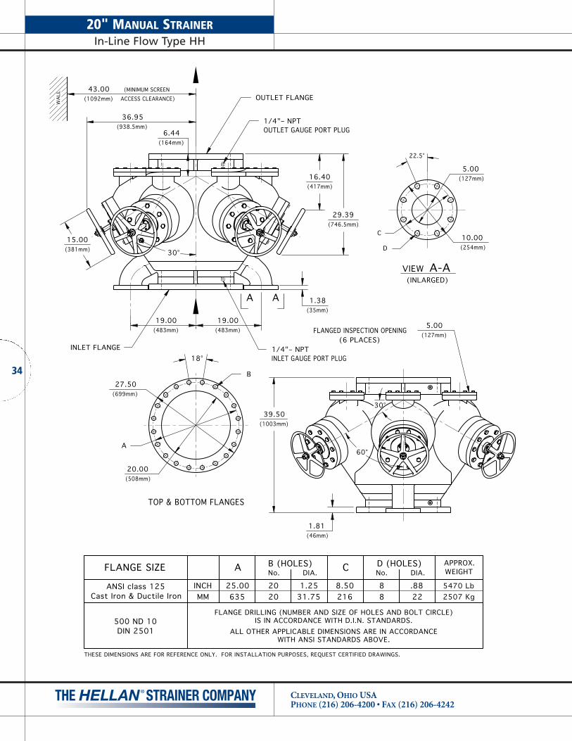
20" MANUAL STRAINERIn-Line Flow Type HH
CLEVELAND, OHIO USAPHONE (216) 206-4200 • FAX (216) 206-4242
34
WA
LL
A
B
TOP & BOTTOM FLANGES
FLANGED INSPECTION OPENING
30°
1/4"– NPT(6 PLACES)
(MINIMUM SCREENACCESS CLEARANCE) OUTLET FLANGE
INLET FLANGE
C
22.5°
D
60°
30°
18° INLET GAUGE PORT PLUG
OUTLET GAUGE PORT PLUG1/4"– NPT
AA
VIEW A-A(INLARGED)
43.00(1092mm)
36.95(938.5mm)
(164mm)6.44
(417mm)16.40
(746.5mm)29.39
(381mm)15.00
(35mm)1.38
(483mm)19.00
(483mm)19.00
(1003mm)39.50
(46mm)1.81
(127mm)5.00
(254mm)10.00
(508mm)20.00
(699mm)27.50
(127mm)5.00
FLANGE DRILLING (NUMBER AND SIZE OF HOLES AND BOLT CIRCLE)IS IN ACCORDANCE WITH D.I.N. STANDARDS.
ALL OTHER APPLICABLE DIMENSIONS ARE IN ACCORDANCEWITH ANSI STANDARDS ABOVE.
500 ND 10DIN 2501
FLANGE SIZE
ANSI class 125Cast Iron & Ductile Iron MM
INCH
A
25.00635
C
2168.50
2507 Kg5470 Lb
WEIGHTAPPROX.
2020
No.
1.2531.75
DIA.B (HOLES)
.8888 22
DIA.D (HOLES)No.
THESE DIMENSIONS ARE FOR REFERENCE ONLY. FOR INSTALLATION PURPOSES, REQUEST CERTIFIED DRAWINGS.

FOUNDRY
U.S. PA
TENT
No. RE
35560
ASTM A
278-64 C
LASS
30
HELLA
N
MARK
HEAT
CODE
FOUNDRY
U.S. PA
TENT
No. RE
35560
ASTM A
278-64 C
LASS
30
HELLA
N2 IN
CH
MARK
HEAT
CODE
CUSTOMERPIPING PIPING
CUSTOMER
PRESSURE SWITCHSUPPLIED BY C.G.C.MOUNTED BY CUST.
ASTM A216 WCB
ASTM A216 WCB
ASTM A278-64 CLASS 30
ASTM A278-64 CLASS 30
Cast Iron & Ductile Iron2" NPT
Cast Steel2" NPT
1–1/2 NPTCast Steel
1–1/2 NPTCast Iron & Ductile Iron
2"
1–1/2"
FLANGE SIZESIZESTRAINER
46 Kg101 Lb
104 Lb47 Kg
47 Kg104 Lb
101 Lb46 Kg
MATERIAL APPROX.WEIGHT
THESE DIMENSIONS ARE FOR REFERENCE ONLY. FOR INSTALLATION PURPOSES, REQUEST CERTIFIED DRAWINGS.ORIENTATION – DRAIN MUST BE DOWN.
2.88
7.50
1.5
INSPECTIONOPENING
13
.881
7.0
0SC
REEN
REM
OV
AL
3.3
INLE
T &
OU
TLET
4.38
GEARB
OX RE
MOVAL
5.94
SCRE
EN R
EMOVAL
9.36 4.20
4.88
9.50REF
3.38
1" NPTSOLIDS FLUSH OUTLET
MOTORIZED DRAIN VALVE
5.1
2ø
WALL
VIEW A-A
(1/3
H.P
.)SC
REEN
DRI
VE
MO
TOR
35
1-1/2" & 2" AUTOMATIC STRAINERIn-Line Flow Type TSA
CLEVELAND, OHIO USAPHONE (216) 206-4200 • FAX (216) 206-4242
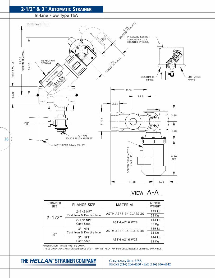
2-1/2" & 3" AUTOMATIC STRAINERIn-Line Flow Type TSA
CLEVELAND, OHIO USAPHONE (216) 206-4200 • FAX (216) 206-4242
36
025TS14-0
0RSCO
DEHEA
T
MARKFO
UNDRY
HELLA
N
U.S. PA
TENT
No. RE
35560
ASTM A
278-64 C
LASS
30
CUSTOMER
MARK
HELLA
N
ASTM A
278-64 C
LASS
30
U.S. PA
TENT
No. RE
35560
FOUNDRY
PIPING
CODE
HEAT
2 INCH
MOUNTED BY CUST.SUPPLIED BY C.G.C.PRESSURE SWITCH
CUSTOMERPIPING
3.75
9.75
2.25
INSPECTIONOPENING
15
.381
8.5
0SC
REEN
REM
OV
AL
4.6
2ø
INLE
T &
OU
TLET
4.38
GEARB
OX RE
MOVAL
7.78
SCRE
EN R
EMOVAL
11.38 4.20
4.88
9.50REF
3.38
1–1/2" NPTSOLIDS FLUSH OUTLET
MOTORIZED DRAIN VALVE
5.1
2ø
WALL
VIEW A-A
(1/3
H.P
.)SC
REEN
DRI
VE
MO
TOR
ASTM A216 WCB
ASTM A216 WCB
ASTM A278-64 CLASS 30
ASTM A278-64 CLASS 30
Cast Iron & Ductile Iron3" NPT
Cast Steel3" NPT
2–1/2 NPTCast Steel
2–1/2 NPTCast Iron & Ductile Iron
3"
2–1/2"
FLANGE SIZESIZESTRAINER
63 Kg139 Lb
144 Lb65 Kg
65 Kg144 Lb
139 Lb63 Kg
MATERIAL APPROX.WEIGHT
THESE DIMENSIONS ARE FOR REFERENCE ONLY. FOR INSTALLATION PURPOSES, REQUEST CERTIFIED DRAWINGS.ORIENTATION – DRAIN MUST BE DOWN.

37
CUSTOMER PIPING
CUSTOMERPRESSURE SWITCHSUPPLIED BY C.G.C.MOUNTED BY CUST.AS SHOWN
CLASS 150FOR ANSI FLANGE
PIPING
TOP & SIDEFLANGE
FLANGEOUTLET
C
7.50(191mm)
FLANGEINLET
(435mm)
(191mm)
17.12
B
7.50
FOR SCREEN REMOVAL)
(MINIMUM CLEARANCE
(360mm)14.19
C
(76mm)
4 HOLES
3.00
(152mm)6.00
.75 DIA (19mm)
A
B(172mm)6.75
(375mm)14.75
(159mm)6.25
1–1/2" NPTSOLIDS FLUSH OUTLET
STRAIGHT NIPPLE
MOTORIZED DRAIN VALVE
3.75 (95mm) DIA.FLANGED INSPECTION OPENING
O-RING SEALED
.06(1.5mm)
5.00(127mm)
SCREEN DRIVE MOTOR(1/3 H.P.)
WA
LL
FLANGE DRILLING (NUMBER AND SIZE OF HOLES AND BOLT CIRCLE)IS IN ACCORDANCE WITH D.I.N. STANDARDS.
ALL OTHER APPLICABLE DIMENSIONS ARE IN ACCORDANCE WITH ANSI STANDARDS ABOVE.
ANSI class 150
75 ND 10DIN 2501
Cast Steel5.69144
14.19360MM
INCH .9424 74 Kg
163 Lb
ANSI class 125Cast Iron & Ductile Iron
B
5.50
A
14.00INCH140356MM
C
.7519
155 Lb
WEIGHTAPPROX.
69 Kg
FLANGE SIZE
THESE DIMENSIONS ARE FOR REFERENCE ONLY. FOR INSTALLATION PURPOSES, REQUEST CERTIFIED DRAWINGS.
3" AUTOMATIC STRAINERAngle Flow Type AA
CLEVELAND, OHIO USAPHONE (216) 206-4200 • FAX (216) 206-4242

4" AUTOMATIC STRAINERIn-Line Flow Type DA
CLEVELAND, OHIO USAPHONE (216) 206-4200 • FAX (216) 206-4242
38
OUTLET FLANGE
SWAGE NIPPLE
MOTORIZED DRAIN VALVE
SCREEN DRIVE MOTOR (1/3 H.P.)
WA
LL
C
EF
D
TOP & BOTTOM FLANGES
(375mm)
20.17(512mm)
(MINIMUM SCREENACCESS CLEARANCE)
16.62(422mm)
33.24(844mm)
30°
M
14.75
D
(INLET GAUGE PORT)1/4" NPT
1/4" NPT(OUTLET GAUGE PORT)
DIFF. PRESSURE SWITCHWITH FITTINGS
2–1/2"– 12 UNFO-RING PLUG SCREEN DRIVE
MOTOR (1/3 HP)
G
R
A
B
INLET FLANGE
250, 150, 300 & DINFOR ANSI FLANGE CLASS
.06 (1.5mm)
C
100 ND 16DIN 2501
FLANGE DRILLING (NUMBER AND SIZE OF HOLES AND BOLT CIRCLE) IS IN ACCORDANCE WITH D.I.N. STANDARDS.
ALL OTHER APPLICABLE DIMENSIONS ARE IN ACCORDANCE WITH ANSI STANDARDS ABOVE.
4.191064.501144.191064.50114
8.91INCHANSI class 125
226MMCast Steel
100 ND 10
Cast SteelANSI class 300
DIN 2501
2349.22
MMINCH
ANSI class 150
Cast Iron & Ductile IronANSI class 250
Cast Iron & Ductile Iron
8.912349.22226
INCHMM
INCHMM
FLANGE SIZE A320 Lb7.5016.009.00NA.946.00 16.948 .75
19140622915724152 86.94176
1.2532
6.31160
7.88200
16.62422
10.00254
88
NA6.941766.19
241.2532.94
1526.311606.00
1917.882007.50
40616.62422
16.00
22910.002549.00
8888
150 Kg3631914.62371
.8822 159 Kg
350 Lb
43014.56370
14.31
19.8822.75 330 Lb
154 Kg340 Lb145 Kg
(HOLES)EDCB No.J
HGF MDIA. WEIGHTAPPROX.
2" NPT SOLIDSFLUSH OUTLET
4.31(109mm)
34914.04357
14.04357
13.73
13.73349
R
H 4.00(102mm)
J
THESE DIMENSIONS ARE FOR REFERENCE ONLY. FOR INSTALLATION PURPOSES, REQUEST CERTIFIED DRAWINGS.

OUTLET FLANGE
SWAGE NIPPLE
MOTORIZED DRAIN VALVE
SCREEN DRIVE MOTOR (1/3 H.P.)
WA
LL
P
(375mm)
26.05(662mm)
(MINIMUM SCREENACCESS CLEARANCE)
20.19(513mm)
40.38(1025mm)
30°
M
C
14.75
D
(INLET GAUGE PORT)1/4" NPT
1/4" NPT(OUTLET GAUGE PORT)
DIFF. PRESSURE SWITCHWITH FITTINGS
SCREEN DRIVEMOTOR (1/3 HP)
G
R
A
B
O-RING SEALEDOPENING,SCREEN INSP.3.25 (82mm)
.06 (1.5mm)D
FE
C
INLET FLANGE
429 279 Kg22 48312318 530 270192 37 216MM 307Cast Steel 135
FLANGE DRILLING (NUMBER AND SIZE OF HOLES AND BOLT CIRCLE)IS IN ACCORDANCE WITH D.I.N. STANDARDS.
ALL OTHER APPLICABLE DIMENSIONS ARE IN ACCORDANCE WITH ANSI STANDARDS ABOVE.
DIN 2501150 ND 10
DIN 2501150 ND 16
29512.07307
11.62
12.07295
11.62
MMINCH
Cast Iron & Ductile Iron
ANSI class 150
INCHANSI class 300
Cast Steel MM
AFLANGE SIZE
MMINCH
Cast Iron & Ductile Iron
ANSI class 250
ANSI class 125 INCH
9.50270
10.62241
10.62241
9.50
7.12192
1.0037
7.56 1.44181 25
5.311244.88135
11.00318
20.00530
8.50246
12.50 20.888.50216 279 508
B C D
7.56181
1.4425
7.12 1.00
5.311244.88
F G HE
12.50279
20.88508
9.69NANA 11.00 20.00
16.45
16.89
429
418.8822
19.62484
.88 19.0022 498
812
128
268 Kg585 Lb
615 Lb266 Kg
16.45
16.89
R
418
DIA. MJNo.
(HOLES)
.8822
19.06495
128
.888 19.50
APPROX.WEIGHT
254 Kg590 Lb
560 Lb
H (152mm)6.00
J
TOP & BOTTOM FLANGESFOR ANSI FLANGE CLASS250, 150, 300 & DIN
FLUSH OUTLET2" NPT SOLIDS
6.12
1526.001556.12155
1556.12
P
THESE DIMENSIONS ARE FOR REFERENCE ONLY. FOR INSTALLATION PURPOSES, REQUEST CERTIFIED DRAWINGS.
39
6" AUTOMATIC STRAINERIn-Line Flow Type DA
CLEVELAND, OHIO USAPHONE (216) 206-4200 • FAX (216) 206-4242
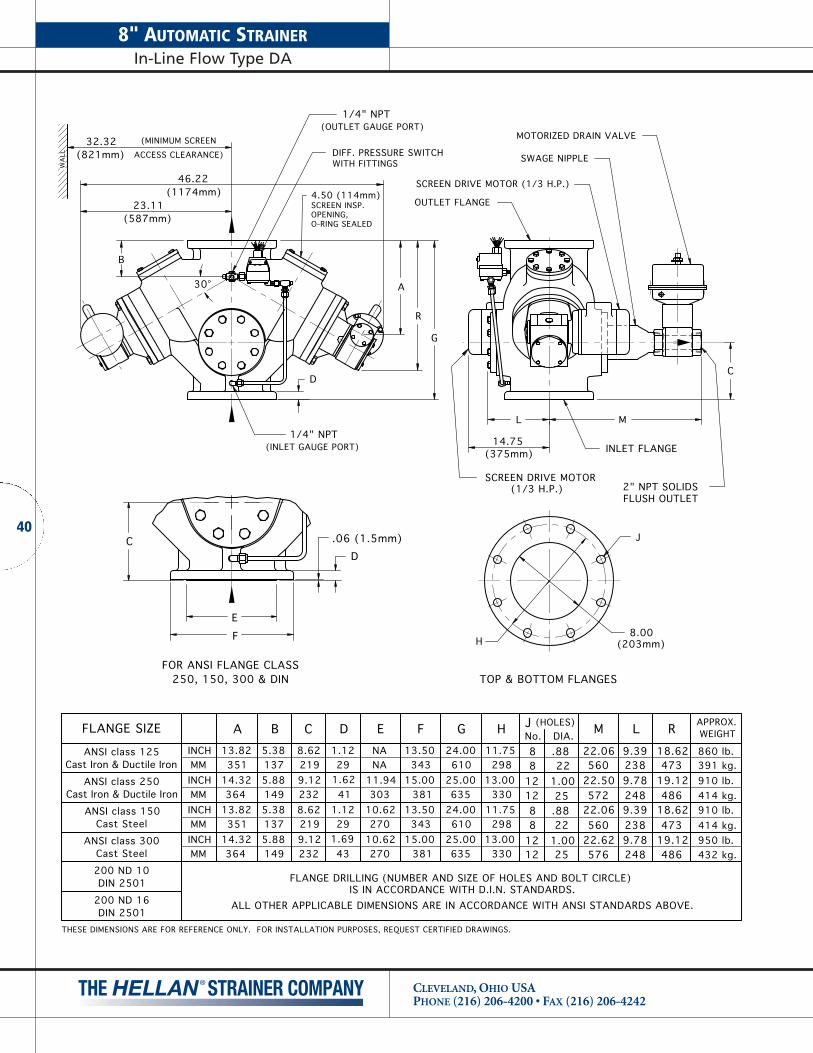
8" AUTOMATIC STRAINERIn-Line Flow Type DA
CLEVELAND, OHIO USAPHONE (216) 206-4200 • FAX (216) 206-4242
40
WA
LL
L
(375mm)
32.32(821mm)
(MINIMUM SCREENACCESS CLEARANCE)
23.11(587mm)
46.22(1174mm)
30°
M
C
14.75
D
(INLET GAUGE PORT)1/4" NPT
1/4" NPT(OUTLET GAUGE PORT)
DIFF. PRESSURE SWITCHWITH FITTINGS
G
R
A
B
.06 (1.5mm)
FOR ANSI FLANGE CLASS250, 150, 300 & DIN
D
FE
C
INLET FLANGE
TOP & BOTTOM FLANGES
H (203mm)8.00
J
SCREEN DRIVE MOTOR (1/3 H.P.)
MOTORIZED DRAIN VALVE
SWAGE NIPPLE
OUTLET FLANGE
2" NPT SOLIDSFLUSH OUTLET
O-RING SEALEDOPENING,SCREEN INSP.4.50 (114mm)
(HOLES)No.
FLANGE DRILLING (NUMBER AND SIZE OF HOLES AND BOLT CIRCLE) IS IN ACCORDANCE WITH D.I.N. STANDARDS.
ALL OTHER APPLICABLE DIMENSIONS ARE IN ACCORDANCE WITH ANSI STANDARDS ABOVE.
ANSI class 250 INCH
MMINCH
INCHMM
MM
Cast Steel
ANSI class 300
ANSI class 150
Cast Iron & Ductile Iron
200 ND 16DIN 2501
200 ND 10DIN 2501
Cast Steel
INCHMM
ANSI class 125Cast Iron & Ductile Iron
FLANGE SIZE A B C
12
12128
128
D E F G H
88
J
9.7822.501.00 19.12
56022.62
57222.06
576251.0022.8825
248
2489.392389.78
48619.12
18.62473
486
22.06560
M
22
DIA..88 9.39
238
L WEIGHTAPPROX.
18.62473
R
27043 381 635149364 232 330
1.12
1.69
1.12
1.62
5.3813.82 8.62
29
41
295.88149
1375.38
5.88
137
14.32351
13.82
351
36414.32
8.62
9.12219
9.12232
219NA 13.50 24.00
11.94
27010.62
30310.62
NA
15.00
13.50343
15.00381
343
24.00
25.00610
25.00635
61011.75
29813.00
330
29813.00
11.75
432 kg.
860 lb.391 kg.
950 lb.414 kg.910 lb.414 kg.910 lb.
THESE DIMENSIONS ARE FOR REFERENCE ONLY. FOR INSTALLATION PURPOSES, REQUEST CERTIFIED DRAWINGS.
SCREEN DRIVE MOTOR(1/3 H.P.)
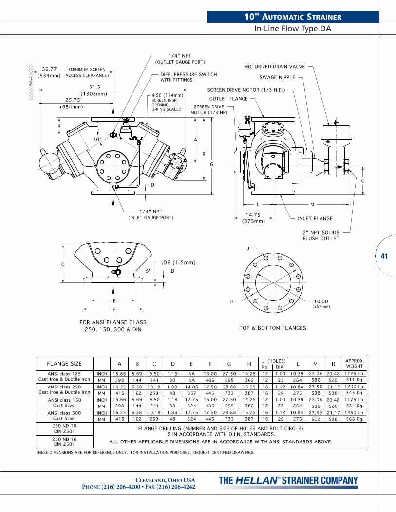
WA
LL
36.77(934mm)
(MINIMUM SCREENACCESS CLEARANCE)
25.75(654mm)
51.5(1308mm)
30°
D
G
R
A
B
C
EF
D
250, 150, 300 & DINFOR ANSI FLANGE CLASS
.06 (1.5mm)
L
(375mm)
M
C
14.75
FLANGE DRILLING (NUMBER AND SIZE OF HOLES AND BOLT CIRCLE)IS IN ACCORDANCE WITH D.I.N. STANDARDS.
ALL OTHER APPLICABLE DIMENSIONS ARE IN ACCORDANCE WITH ANSI STANDARDS ABOVE.
1.1930
1.8848
D
1.1930
1.8848
ANSI class 150
ANSI class 300
DIN 2501250 ND 16
DIN 2501250 ND 10
Cast Steel
Cast Steel
ANSI class 250
ANSI class 125
FLANGE SIZE
Cast Iron & Ductile Iron
Cast Iron & Ductile Iron
5.6915.66 9.50INCH1446.38162
39816.35
415INCHMM
MM 241
25910.19
B
5.691446.38162415
16.35398
15.66
A
INCH
INCH
MM
MM
C
9.50241
10.19259
27.5012.75 16.00406
17.50445324
12.75324
28.88733
699
16.00406
17.50445
E
NANA
14.06357
27.50
28.88
F
733
699
G
20.4812 1.0014.25362
38715.25
121616
251.1229 538
21.17520
(HOLES)
14.25362
15.25387
H
12121616
No.J
1.0025
1.1229
DIA.
53821.17520
20.48
R
10.39 1175 Lb.23.06264
27510.84
58623.69602 568 Kg.
1250 Lb.534 Kg.
27510.84
26410.39
L
23.06586
23.56598
M
545 Kg.1200 Lb.511 Kg.
WEIGHTAPPROX.
1125 Lb.
(254mm)
TOP & BOTTOM FLANGES
10.00H
MOTORIZED DRAIN VALVE
SCREEN DRIVE MOTOR (1/3 H.P.)
OUTLET FLANGE
SWAGE NIPPLE
SCREEN DRIVEMOTOR (1/3 HP)
(OUTLET GAUGE PORT)
DIFF. PRESSURE SWITCHWITH FITTINGS
1/4" NPT
SCREEN INSP.
O-RING SEALEDOPENING,
4.50 (114mm)
INLET FLANGE
2" NPT SOLIDSFLUSH OUTLET
J
(INLET GAUGE PORT)1/4" NPT
THESE DIMENSIONS ARE FOR REFERENCE ONLY. FOR INSTALLATION PURPOSES, REQUEST CERTIFIED DRAWINGS.
41
10" AUTOMATIC STRAINERIn-Line Flow Type DA
CLEVELAND, OHIO USAPHONE (216) 206-4200 • FAX (216) 206-4242
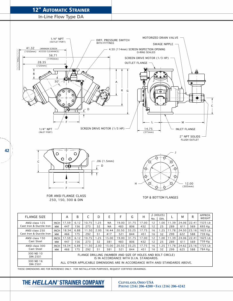
12" AUTOMATIC STRAINERIn-Line Flow Type DA
CLEVELAND, OHIO USAPHONE (216) 206-4200 • FAX (216) 206-4242
42
4.50 (114mm) SCREEN INSPECTION OPENING
WA
LL
41.32(1050mm)
(MINIMUM SCREENACCESS CLEARANCE)
28.35(720mm)
B
D
F
G
56.71(1440mm)
L
L
11.39289
11.78299
11.39289
11.7829932
1.2525
1.0032
1.2525
1.00
1616121216161212
A
INCHMMINCHMMINCHMMINCHMM
17.59447
18.34466
17.59447
18.34466 175
6.881566.121756.881566.12
B
29211.50273
10.75292
11.50273
10.75
C
512.0032
1.2551
2.0032
1.25
D
38115.00381
15.00417
16.44NANA
E
52120.50
48319.00
52120.50
48319.00
F
84433.25806
31.75844
33.25806
31.75
G
45117.75432
17.00451
17.75432
17.00
H JNo. DIA.
(HOLES)
O-RING SEALED
1525 Lb693 Kg1625 Lb739 Kg1625 Lb739 Kg1725 Lb784 Kg
J
250, 150, 300 & DINFOR ANSI FLANGE CLASS
E
.06 (1.5mm)CD
FH
(305mm)12.00
TOP & BOTTOM FLANGES
M
61124.62625
M
24.50611
24.06
24.06622
FLANGE DRILLING (NUMBER AND SIZE OF HOLES AND BOLT CIRCLE)IS IN ACCORDANCE WITH D.I.N. STANDARDS.
ALL OTHER APPLICABLE DIMENSIONS ARE IN ACCORDANCE WITH ANSI STANDARDS ABOVE.
R
A
(OUTLET PORT)1/4" NPT
1/4" NPT(INLET PORT)
DIFF. PRESSURE SWITCHWITH FITTINGS
SCREEN DRIVE MOTOR (1/3 HP)
MOTORIZED DRAIN VALVE
2" NPT SOLIDSFLUSH OUTLET
SWAGE NIPPLE
OUTLET FLANGE
INLET FLANGE
SCREEN DRIVE MOTOR (1/3 HP)
C
(375mm)
DIN 2501300 ND 16
DIN 2501300 ND 10
Cast SteelANSI class 300
Cast SteelANSI class 150
Cast Iron & Ductile IronANSI class 250
Cast Iron & Ductile IronANSI class 125
FLANGE SIZE WEIGHTAPPROX.R
23.16588
22.41
58823.16569
22.41569
14.75
30°
THESE DIMENSIONS ARE FOR REFERENCE ONLY. FOR INSTALLATION PURPOSES, REQUEST CERTIFIED DRAWINGS.
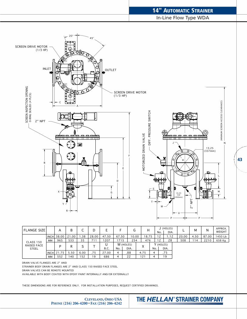
(1/3 HP)SCREEN DRIVE MOTOR
(HOLES)
INCH
INCH
STEELRAISED FACE
MM
CLASS 150
FLANGE SIZE
MMU WR
5.50140
21.75552
P
6.00152
S B.C.27.0068619
T
.7544
No.
53321.00
B
38.00965
A
1.3835
C
120747.50
E
71128.00
D
171567.50
F
O-R
ING
SEA
LED
(4 P
LCS)
SCRE
EN IN
SPEC
TION
OPE
NING
2" NPT
INLET
SCREEN DRIVE MOTOR(1/3 HP)
OUTLET
MO
TORI
ZED
DRA
IN V
ALV
E
(HOLES)Y
.7519
4.7512122
DIA..88
X No.44
DIA.
18.75254
10.00
G
476
H No.
1212
J
20.00508
1.12DIA.
(HOLES)
28
L
1144.50
M
2"
NPT
1450 Lb658 Kg
WEIGHTAPPROX.N
87.002210
DIF
F. P
RESS
URE
SW
ITCH
(MIN
IMU
M S
CREE
N A
CCES
S CL
EARA
NCE
)
THESE DIMENSIONS ARE FOR REFERENCE ONLY. FOR INSTALLATION PURPOSES, REQUEST CERTIFIED DRAWINGS.
F
E
DRAIN VALVE FLANGES ARE 2" ANSISTRAINER BODY DRAIN FLANGES ARE 2" ANSI CLASS 150 RAISED FACE STEELDRAIN VALVES CAN BE REMOTE MOUNTEDAVAILABLE WITH BODY COATED WITH EPOXY PAINT INTERNALLY AND/OR EXTERNALLY
B
GX
R
Y
D
C
45°20°
A
13.25(337mm)
J N
P
W
P
S
T
10.25TYP
(260mm)
U
H
M
L
NAMEPLATE
43
14" AUTOMATIC STRAINERIn-Line Flow Type WDA
CLEVELAND, OHIO USAPHONE (216) 206-4200 • FAX (216) 206-4242
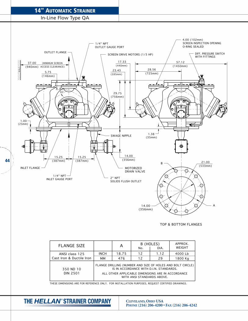
14" AUTOMATIC STRAINERIn-Line Flow Type QA
CLEVELAND, OHIO USAPHONE (216) 206-4200 • FAX (216) 206-4242
44
2" NPT
INLET FLANGE
37.00(940mm)
(MINIMUM SCREENACCESS CLEARANCE)
WA
LL
29.75(756mm)
17.33(440mm)
15.25(387mm) 21.00
(533mm)
(35mm)1.38
(725mm)28.56
(25mm)1.00
5.75(146mm)
30°
57.12(1450mm)
1/4" NPTINLET GAUGE PORT
15.25(387mm)
FLANGE DRILLING (NUMBER AND SIZE OF HOLES AND BOLT CIRCLE)IS IN ACCORDANCE WITH D.I.N. STANDARDS.
ALL OTHER APPLICABLE DIMENSIONS ARE IN ACCORDANCEWITH ANSI STANDARDS ABOVE.
350 ND 10DIN 2501
FLANGE SIZE
ANSI class 125Cast Iron & Ductile Iron MM
INCH
A
18.75476 1800 Kg
4000 Lb
WEIGHTAPPROX.
TOP & BOTTOM FLANGES
A
B
14.00(356mm)
1212
No.
1.1229
DIA.B (HOLES)
SOLIDS FLUSH OUTLET
(356mm)14.00
(595mm)23.43
OUTLET GAUGE PORT
OUTLET FLANGE
1/4" NPTO-RING SEALED
4.00 (102mm)SCREEN INSPECTION OPENING
SWAGE NIPPLE
MOTORIZEDDRAIN VALVE
SCREEN DRIVE MOTORS (1/3 HP) DIFF. PRESSURE SWITCHWITH FITTINGS
THESE DIMENSIONS ARE FOR REFERENCE ONLY. FOR INSTALLATION PURPOSES, REQUEST CERTIFIED DRAWINGS.

INLET OUTLET
DRAIN VALVE FLANGES ARE 2" ANSI CLASS 125 FLAT FACED CAST IRONSTRAINER BODY DRAIN FLANGES ARE 2" ANSI CLASS 125 FLAT FACEDDRAIN VALVE CAN BE REMOTE MOUNTEDAVAILABLE WITH BODY COATED WITH EPOXY PAINT INTERNALLY AND/OR EXTERNALLY
2" NPT
61.7
5
5.00
42.0
0
16.6
3
2.00
2" NPT
SCREEN DRIVE MOTOR
(1/2 HP)
44.00
(MIN
IMUM
SCR
EEN
ACC
ESS
CLEA
RANC
E)
SCRE
EN IN
SPEC
TION
OPE
NING
O-RI
NG S
EALE
D (2
PLC
S)
MO
TORI
ZED
DRA
IN V
ALV
E
27.00
20.00DI
FF. P
RESS
URE
SWIT
CH
12 HOLES 1.12 DIAEQ. SPCD. ON21.250 B.C.TYP. 2 PLCS.
88.0
0
21.0
0TY
P
1.38TYP
16"
ANS
I CLA
SS 1
25 F
LAT
FACE
D
9.00
10.0010.00
9.009.00
10.00
2.00 TYP
9.00
10.00
3/4 - 10 TAP X 1.50 DP4HOLES AS SHOWN
FLANGE DRILLING (NUMBER AND SIZE OF HOLES AND BOLT CIRCLE)IS IN ACCORDANCE WITH D.I.N. STANDARDS.
ALL OTHER APPLICABLE DIMENSIONS ARE IN ACCORDANCEWITH ANSI STANDARDS ABOVE.
350 ND 10DIN 2501
FLANGE SIZE
ANSI class 125Cast Iron & Ductile Iron MM
INCH
A
18.75476 658 Kg
1450 Lb
WEIGHTAPPROX.
1212
No.
1.1229
DIA.B (HOLES)
THESE DIMENSIONS ARE FOR REFERENCE ONLY. FOR INSTALLATION PURPOSES, REQUEST CERTIFIED DRAWINGS.
45
14" AUTOMATIC STRAINERIn-Line Flow Type SA
CLEVELAND, OHIO USAPHONE (216) 206-4200 • FAX (216) 206-4242

16" AUTOMATIC STRAINERIn-Line Flow Type WDA
CLEVELAND, OHIO USAPHONE (216) 206-4200 • FAX (216) 206-4242
46
(1/3 HP)SCREEN DRIVE MOTOR
(HOLES)
INCH
INCH
STEELRAISED FACE
MM
CLASS 150
FLANGE SIZE
MMU WR
6.88175
25.50648
P
6.00152
S B.C.36.0091419
T
.7544
No.
59723.50
B
46.001168
A
1.4437
C
127650.25
E
76230.00
D
179170.50
F
O-R
ING
SEA
LED
(4
PLC
S)SC
REEN
INSP
ECTI
ON
OPE
NIN
G
2" NPT
INLET
SCREEN DRIVE MOTOR(1/3 HP)
OUTLET
DIF
F. P
RESS
URE
SW
ITCH
MO
TORI
ZED
DRA
IN V
ALV
E
(HOLES)Y
.7519
4.7512122
DIA..88
X No.44
DIA.
21.25270
10.63
G
540
H No.
1616
J
21.63549
1.12DIA.
(HOLES)
28
L
1144.50
M
2"
NPT
1600 Lb726 Kg
WEIGHTAPPROX.N
91.002311
(MIN
IMU
M S
CREE
N A
CCES
S CL
EARA
NCE
)
THESE DIMENSIONS ARE FOR REFERENCE ONLY. FOR INSTALLATION PURPOSES, REQUEST CERTIFIED DRAWINGS.
F
E
DRAIN VALVE FLANGES ARE 2" ANSISTRAINER BODY DRAIN FLANGES ARE 2" ANSI CLASS 150 RAISED FACE STEELDRAIN VALVES CAN BE REMOTE MOUNTEDAVAILABLE WITH BODY COATED WITH EPOXY PAINT INTERNALLY AND/OR EXTERNALLY
B
G
R
X
Y
D
A
20°45°
JN
15.25(387mm)
U
P
W
P
S
T
14.00TYP
(356mm)
H
M
L
NAMEPLATE

1/4" NPT
OUTLET FLANGE
2" NPT
INLET FLANGE
41.00(1041mm)
(MINIMUM SCREENACCESS CLEARANCE)
WA
LL
32.62(829mm)
19.46(494mm)
17.00(432mm) 23.50
(597mm)
(37mm)1.44
(797mm)31.37
(27mm)1.06
6.25(159mm)
30°
OUTLET GAUGE PORT
62.74(1594mm)
1/4" NPTINLET GAUGE PORT
17.00(432mm)
TOP & BOTTOM FLANGES
A
B
16.00(406mm)
SOLIDS FLUSH OUTLET
(408mm)16.06
(649mm)25.55
5.00 (127mm)
O-RING SEALEDSCREEN INSPECTION OPENING
DIFF. PRESSURE SWITCHWITH FITTINGSSCREEN DRIVE MOTORS (1/3 HP)
SWAGE NIPPLE
MOTORIZEDDRAIN VALVE
FLANGE DRILLING (NUMBER AND SIZE OF HOLES AND BOLT CIRCLE)IS IN ACCORDANCE WITH D.I.N. STANDARDS.
ALL OTHER APPLICABLE DIMENSIONS ARE IN ACCORDANCEWITH ANSI STANDARDS ABOVE.
400 ND 10DIN 2501
FLANGE SIZE
ANSI class 125Cast Iron & Ductile Iron MM
INCH
A
21.25540 2100 Kg
4600 Lb
WEIGHTAPPROX.
1616
No.
1.1229
DIA.B (HOLES)
THESE DIMENSIONS ARE FOR REFERENCE ONLY. FOR INSTALLATION PURPOSES, REQUEST CERTIFIED DRAWINGS.
47
16" AUTOMATIC STRAINERIn-Line Flow Type QA
CLEVELAND, OHIO USAPHONE (216) 206-4200 • FAX (216) 206-4242

16" AUTOMATIC STRAINERIn-Line Flow Type SA
CLEVELAND, OHIO USAPHONE (216) 206-4200 • FAX (216) 206-4242
48
INLET OUTLET
DRAIN VALVE FLANGES ARE 2" ANSI CLASS 125 FLAT FACED CAST IRONSTRAINER BODY DRAIN FLANGES ARE 2" ANSI CLASS 125 FLAT FACEDDRAIN VALVE CAN BE REMOTE MOUNTEDAVAILABLE WITH BODY COATED WITH EPOXY PAINT INTERNALLY AND/OR EXTERNALLY
2" NPT
61.7
5
5.00
42.0
0
16.6
3
2.00
2" NPT
SCREEN DRIVE MOTOR
(1/2 HP)
44.00
(MIN
IMUM
SCR
EEN
ACC
ESS
CLEA
RANC
E)
SCRE
EN IN
SPEC
TION
OPE
NING
O-RI
NG S
EALE
D (2
PLC
S)
MO
TORI
ZED
DRA
IN V
ALV
E
27.00
20.00DI
FF. P
RESS
URE
SWIT
CH
16 HOLES 1.12 DIAEQ. SPCD. ON21.250 B.C.TYP. 2 PLCS.
88.0
0
23.5
0TY
P
1.44TYP
16"
ANS
I CLA
SS 1
25 F
LAT
FACE
D
9.00
10.0010.00
9.009.00
10.00
2.00 TYP
9.00
10.00
3/4 - 10 TAP X 1.50 DP4HOLES AS SHOWN
FLANGE DRILLING (NUMBER AND SIZE OF HOLES AND BOLT CIRCLE)IS IN ACCORDANCE WITH D.I.N. STANDARDS.
ALL OTHER APPLICABLE DIMENSIONS ARE IN ACCORDANCEWITH ANSI STANDARDS ABOVE.
400 ND 10DIN 2501
FLANGE SIZE
ANSI class 125Cast Iron & Ductile Iron MM
INCH
A
21.25540 726 Kg
1600 Lb
WEIGHTAPPROX.
1616
No.
1.1229
DIA.B (HOLES)
THESE DIMENSIONS ARE FOR REFERENCE ONLY. FOR INSTALLATION PURPOSES, REQUEST CERTIFIED DRAWINGS.

(1/2 HP)SCREEN DRIVE MOTOR
(HOLES)
INCH
INCH
STEELRAISED FACE
MM
CLASS 150
FLANGE SIZE
MMU WR
8.00203
28.50724
P
7.50191
S B.C.40.00101624
T
.9444
No.
69927.50
B
50.001270
A
1.6943
C
155661.25
E
92136.25
D
211583.25
F
O-R
ING
SEA
LED
(4
PLC
S)SC
REEN
INSP
ECTI
ON
OPE
NIN
G
2" NPT
INLET
SCREEN DRIVE MOTOR(1/2 HP)
OUTLET
DIF
F. P
RESS
URE
SW
ITCH
MO
TORI
ZED
DRA
IN V
ALV
E
(HOLES)Y
.7519
6.0015229
DIA.1.12
X No.44
DIA.
25.00337
13.25
G
635
H No.
2020
J
24.75629
1.25DIA.
(HOLES)
32
L
1405.50
M
2"
NPT
2300 Lb1043 Kg
WEIGHTAPPROX.N
109.002769
(MIN
IMU
M S
CREE
N A
CCES
S CL
EARA
NCE
)
THESE DIMENSIONS ARE FOR REFERENCE ONLY. FOR INSTALLATION PURPOSES, REQUEST CERTIFIED DRAWINGS.
F
E
DRAIN VALVE FLANGES ARE 3" ANSISTRAINER BODY DRAIN FLANGES ARE 3" ANSI CLASS 150 RAISED FACE STEELDRAIN VALVES CAN BE REMOTE MOUNTEDAVAILABLE WITH BODY COATED WITH EPOXY PAINT INTERNALLY AND/OR EXTERNALLY
B
GX
R
Y
D
CA
20°45°
JN
19.25(489mm)
U
P
W
P
15.00TYP
(381mm)
H
M
L
NAMEPLATENAMEPLATE
49
20" AUTOMATIC STRAINERIn-Line Flow Type WDA
CLEVELAND, OHIO USAPHONE (216) 206-4200 • FAX (216) 206-4242

20" AUTOMATIC STRAINERIn-Line Flow Type HA
CLEVELAND, OHIO USAPHONE (216) 206-4200 • FAX (216) 206-4242
50
WA
LL
A
B
TOP & BOTTOM FLANGES
FLANGED INSPECTION OPENING
30°
1/4"– NPT
(6 PLACES)
(MINIMUM SCREENACCESS CLEARANCE)
OUTLET FLANGE
INLET FLANGE
30°
INLET GAUGE PORT
OUTLET GAUGE PORT1/4"– NPT43.00
(1092mm)
33.82(859mm)
(164mm)6.44 (535mm)
21.06
(690mm)27.16
(35mm)1.38
(483mm)19.00
(483mm)19.00
(1003mm)39.50
(46mm)1.81
(508mm)20.00
(699mm)27.50
(127mm)5.00
60°
SCREEN DRIVE MOTORS (1/3 HP)
(408mm)16.06
SWAGENIPPLE
MOTORIZEDDRAIN VALVE
2" NPTSOLIDS FLUSH OUTLET
DIFF. PRESSURE SWITCHWITH FITTINGS
FLANGE DRILLING (NUMBER AND SIZE OF HOLES AND BOLT CIRCLE)IS IN ACCORDANCE WITH D.I.N. STANDARDS.
ALL OTHER APPLICABLE DIMENSIONS ARE IN ACCORDANCEWITH ANSI STANDARDS ABOVE.
500 ND 10DIN 2501
FLANGE SIZE
ANSI class 125Cast Iron & Ductile Iron MM
INCH
A
25.00635 2588 Kg
5750 Lb
WEIGHTAPPROX.
2020
No.
1.2531.75
DIA.B (HOLES)
THESE DIMENSIONS ARE FOR REFERENCE ONLY. FOR INSTALLATION PURPOSES, REQUEST CERTIFIED DRAWINGS.

(1/2 HP)SCREEN DRIVE MOTOR
(HOLES)
INCH
INCH
STEELRAISED FACE
MM
CLASS 150
FLANGE SIZE
MMU WR
11.00279
31.25794
P
7.50191
S B.C.48.00121924
T
.9444
No.
81332.00
B
58.001473
A
1.8848
C
173468.25
E
104841.25
D
234392.25
F
O-R
ING
SEA
LED
(6
PLC
S)SC
REEN
INSP
ECTI
ON
OPE
NIN
G
2" NPT
INLET
SCREEN DRIVE MOTOR(1/2 HP)
OUTLET
DIF
F. P
RESS
URE
SW
ITCH
MO
TORI
ZED
DRA
IN V
ALV
E
(HOLES)Y
.7519
6.0015229
DIA.1.12
X No.44
DIA.
29.50337
13.25
G
749
H No.
2020
J
30.00762
1.38DIA.
(HOLES)
35
L
1405.50
M
2"
NPT
3700 Lb1678 Kg
WEIGHTAPPROX.N
1203048
(MIN
IMU
M S
CREE
N A
CCES
S CL
EARA
NCE
)
THESE DIMENSIONS ARE FOR REFERENCE ONLY. FOR INSTALLATION PURPOSES, REQUEST CERTIFIED DRAWINGS.
F
E
DRAIN VALVE FLANGES ARE 3" ANSISTRAINER BODY DRAIN FLANGES ARE 3" ANSI CLASS 150 RAISED FACE STEELDRAIN VALVES CAN BE REMOTE MOUNTEDAVAILABLE WITH BODY COATED WITH EPOXY PAINT INTERNALLY AND/OR EXTERNALLY
B
GX
RY
D
C
25°45°
A
N23.25(591mm)
UP
T
P
S17.75TYP
(451mm)
W
H
J
M
L
NAMEPLATE
51
24" AUTOMATIC STRAINERIn-Line Flow Type WDA
CLEVELAND, OHIO USAPHONE (216) 206-4200 • FAX (216) 206-4242

30" AUTOMATIC STRAINERIn-Line Flow Type WDA
CLEVELAND, OHIO USAPHONE (216) 206-4200 • FAX (216) 206-4242
52
(1/2 HP)SCREEN DRIVE MOTOR
(HOLES)
INCH
INCH
STEELFLAT FACE(150 PSI)
MM
CLASS 125LW
FLANGE SIZE
MMU WR
12.00305
23.75603
P
9.00229
S B.C.60.00152424
T
.9444
No.
98438.75
B
76.001930
A
1.0025
C
226089.00
E
136553.75
D
115.002921
F
O-R
ING
SEA
LED
(6
PLC
S)SC
REEN
INSP
ECTI
ON
OPE
NIN
G
2" NPT
INLET
SCREEN DRIVE MOTOR(1/2 HP)
OUTLET
DIF
F. P
RESS
URE
SW
ITCH
MO
TORI
ZED
DRA
IN V
ALV
E
(MIN
IMU
M S
CREE
N A
CCES
S CL
EARA
NCE
)
2" NPT
(HOLES)Y
7.5019035
DIA.1.38
X No.88 19
DIA..75
36.00502
19.75
G
914
H No.
2828
J
38.00965
1.38DIA.
(HOLES)
35
L
1656.50
M
7000 Lb3175 Kg
WEIGHTAPPROX.N
152.003861
THESE DIMENSIONS ARE FOR REFERENCE ONLY. FOR INSTALLATION PURPOSES, REQUEST CERTIFIED DRAWINGS.
F
E
DRAIN VALVE FLANGES ARE 4" ANSISTRAINER BODY DRAIN FLANGES ARE 4" ANSI CLASS 150 RAISED FACE STEELDRAIN VALVES CAN BE REMOTE MOUNTEDAVAILABLE WITH BODY COATED WITH EPOXY PAINT INTERNALLY AND/OR EXTERNALLY
B
GX
RY
D
A
45°25°
J
N
P
29.25(743mm)
U
P
W
23.75TYP
(603mm)
H
L
M
NAMEPLATE

SCREEN DRIVE MOTOR
(HOLES)
INCH
INCH
STEELFLAT FACE(150 PSI)
MM
CLASS 125LW
FLANGE SIZE
MMU WR
11.75298
45.251149
P
9.00229
S B.C.72.00182924
T
.9444
No.
116846.00
B
90.002286
A
1.1329
C
2623103.25
E
152460.00
D
133.503391
F
(1/2 HP)SCREEN DRIVE MOTOR
O-R
ING
SEA
LED
(8
PLC
S)SC
REEN
INSP
ECTI
ON
OPE
NIN
G
2" NPT
INLET
(1/2 HP)
OUTLET
DIF
F. P
RESS
URE
SW
ITCH
MO
TORI
ZED
DRA
IN V
ALV
E
2" NPT
(HOLES)Y
.7519
7.5019035
DIA.1.38
X No.88
DIA.
42.75508
20.00
G
1086
H No.
3232
J
44.001118
1.63DIA.
(HOLES)
41
L
1656.50
M
12000 Lb5443 Kg
WEIGHTAPPROX.N
177.004496
(MIN
IMU
M S
CREE
N A
CCES
S CL
EARA
NCE
)
THESE DIMENSIONS ARE FOR REFERENCE ONLY. FOR INSTALLATION PURPOSES, REQUEST CERTIFIED DRAWINGS.
F
E
DRAIN VALVE FLANGES ARE 4" ANSISTRAINER BODY DRAIN FLANGES ARE 4" ANSI CLASS 150 RAISED FACE STEELDRAIN VALVES CAN BE REMOTE MOUNTEDAVAILABLE WITH BODY COATED WITH EPOXY PAINT INTERNALLY AND/OR EXTERNALLY
B
GX
RY
D
CA
20°
45°
JN
35.00(889mm)
U
P
T
P
S
W
29.75TYP
(756mm)
H
M
L
NAMEPLATE
53
36" AUTOMATIC STRAINERIn-Line Flow Type WDA
CLEVELAND, OHIO USAPHONE (216) 206-4200 • FAX (216) 206-4242

11⁄2" & 2" TSH/TSA AND 2" AH STRAINERClean Pressure Drop vs. Flow Rate
CLEVELAND, OHIO USAPHONE (216) 206-4200 • FAX (216) 206-4242
54
1 1.5 2 2.5 3(×10)
4 5 6 7 8 9100 1.5 2 2.5 3
(×100)4 5 6 7 8 9 1000
Water Flow Rate GPM
Pre
ssur
e D
rop
, PS
I
1098
7
6
5
4
3
2.5
2
1.5
1.9.8
.7
.6
.5
.4
.3
.25
.2
.15
.1
1/4, 3/16" Scr. Perf.
1/8" Scr. Perf.
1/16, 1/32" Scr. Perf.
3/32" Scr. Perf.
.70
Pre
ssur
e D
rop
, Bar
s*
.60
.50
.40
.35
.30
.25
.20
.15
.10
.070
.060
.050
.040
.030
.025
.020
.015
.010
.007
200100 300 500 600 700 800400 100050 60 70 8040 1500 2000 3000 3800Water Flow Rate, Liters Per Minute**

1 1.5 2 2.5 3 4 5 6 7 8 9100 1.5 2 2.5 3 4 5 6 7 8 9
Water Flow Rate GPM
Pre
ssur
e D
rop
, PS
I
1098
7
6
5
4
3
2.5
2
1.5
.015" Wedge-Wire
.009" Wedge-Wire
.007" Wedge-Wire
.005" Wedge-Wire
.004" Wedge-Wire
.70
Pre
ssur
e D
rop
, Bar
s*
.60
.50
.40
.35
.30
.25
.20
.15
.10
.070
.060
.050
.040
.030
.025
.020
.015
.010
.007
200100 300 500 600 700 800400 100050 60 70 8040 1500 2000 3000 3800Water Flow Rate, Liters Per Minute**
(×10)(×100)
1000
1.9.8
.7
.6
.5
.4
.3
.25
.2
.15
.1
55
11⁄2" & 2" TSH/TSA STRAINERClean Pressure Drop vs. Flow Rate
CLEVELAND, OHIO USAPHONE (216) 206-4200 • FAX (216) 206-4242
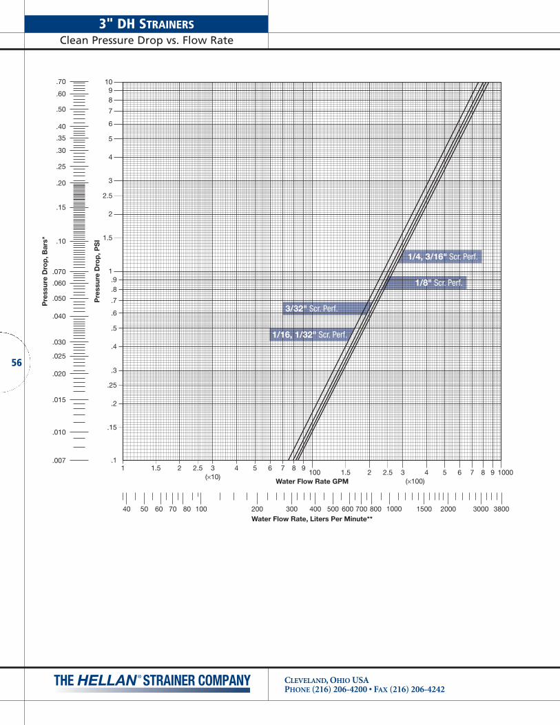
3" DH STRAINERSClean Pressure Drop vs. Flow Rate
CLEVELAND, OHIO USAPHONE (216) 206-4200 • FAX (216) 206-4242
56
1 1.5 2 2.5 3 4 5 6 7 8 9100 1.5 2 2.5 3 4 5 6 7 8 9
Water Flow Rate GPM
Pre
ssur
e D
rop
, PS
I
1098
7
6
5
4
3
2.5
2
1.5
1/4, 3/16" Scr. Perf.
1/8" Scr. Perf.
1/16, 1/32" Scr. Perf.
3/32" Scr. Perf.
.70
Pre
ssur
e D
rop
, Bar
s*
.60
.50
.40
.35
.30
.25
.20
.15
.10
.070
.060
.050
.040
.030
.025
.020
.015
.010
.007
200100 300 500 600 700 800400 100050 60 70 8040 1500 2000 3000 3800Water Flow Rate, Liters Per Minute**
(×10)(×100)
1000
1.9.8
.7
.6
.5
.4
.3
.25
.2
.15
.1

1 1.5 2 2.5 3 4 5 6 7 8 9100 1.5 2 2.5 3 4 5 6 7 8 9
Water Flow Rate GPM
Pre
ssur
e D
rop
, PS
I
1098
7
6
5
4
3
2.5
2
1.5
.70
Pre
ssur
e D
rop
, Bar
s*
.60
.50
.40
.35
.30
.25
.20
.15
.10
.070
.060
.050
.040
.030
.025
.020
.015
.010
.007
200100 300 500 600 700 800400 100050 60 70 8040 1500 2000 3000 3800Water Flow Rate, Liters Per Minute**
(×10)(×100)
1000
1.9.8
.7
.6
.5
.4
.3
.25
.2
.15
.1
1/4, 3/16" Scr. Perf.
1/8" Scr. Perf.
1/16, 1/32" Scr. Perf.
3/32" Scr. Perf.
57
2-1/2" AH STRAINERSClean Pressure Drop vs. Flow Rate
CLEVELAND, OHIO USAPHONE (216) 206-4200 • FAX (216) 206-4242

21⁄2" & 3" TSH/TSA AND 3" AH/AA STRAINERSClean Pressure Drop vs. Flow Rate
CLEVELAND, OHIO USAPHONE (216) 206-4200 • FAX (216) 206-4242
58
1 1.5 2 2.5 3 4 5 6 7 8 9100 1.5 2 2.5 3 4 5 6 7 8 9
Water Flow Rate GPM
Pre
ssur
e D
rop
, PS
I
1098
7
6
5
4
3
2.5
2
1.5
1/4, 3/16" Scr. Perf.
1/8" Scr. Perf.
1/16, 1/32" Scr. Perf.
3/32" Scr. Perf.
.70
Pre
ssur
e D
rop
, Bar
s*
.60
.50
.40
.35
.30
.25
.20
.15
.10
.070
.060
.050
.040
.030
.025
.020
.015
.010
.007
200100 300 500 600 700 800400 100050 60 70 8040 1500 2000 3000 3800Water Flow Rate, Liters Per Minute**
(×10)(×100)
1000
1.9.8
.7
.6
.5
.4
.3
.25
.2
.15
.1
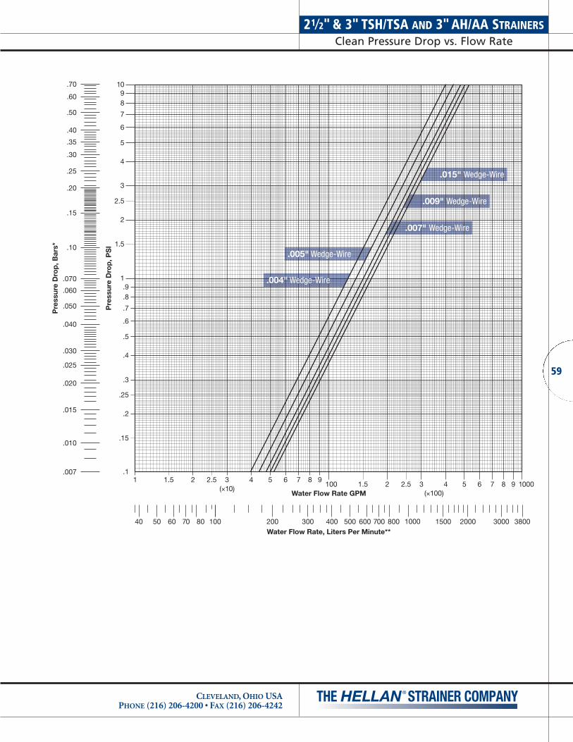
1 1.5 2 2.5 3 4 5 6 7 8 9100 1.5 2 2.5 3 4 5 6 7 8 9
Water Flow Rate GPM
Pre
ssur
e D
rop
, PS
I
1098
7
6
5
4
3
2.5
2
1.5
.015" Wedge-Wire
.009" Wedge-Wire
.007" Wedge-Wire
.005" Wedge-Wire
.004" Wedge-Wire
.70
Pre
ssur
e D
rop
, Bar
s*
.60
.50
.40
.35
.30
.25
.20
.15
.10
.070
.060
.050
.040
.030
.025
.020
.015
.010
.007
200100 300 500 600 700 800400 100050 60 70 8040 1500 2000 3000 3800Water Flow Rate, Liters Per Minute**
(×10)(×100)
1000
1.9.8
.7
.6
.5
.4
.3
.25
.2
.15
.1
59
21⁄2" & 3" TSH/TSA AND 3" AH/AA STRAINERSClean Pressure Drop vs. Flow Rate
CLEVELAND, OHIO USAPHONE (216) 206-4200 • FAX (216) 206-4242

4" DH/DA STRAINERSClean Pressure Drop vs. Flow Rate
CLEVELAND, OHIO USAPHONE (216) 206-4200 • FAX (216) 206-4242
60
1 1.5 2 2.5 3 4 5 6 7 8 9100 1.5 2 2.5 3 4 5 6 7 8 9
Water Flow Rate GPM
Pre
ssur
e D
rop
, PS
I
1098
7
6
5
4
3
2.5
2
1.5
1/4, 3/16" Scr. Perf.
1/8" Scr. Perf.
1/16, 1/32" Scr. Perf.
3/32" Scr. Perf.
.70
Pre
ssur
e D
rop
, Bar
s*
.60
.50
.40
.35
.30
.25
.20
.15
.10
.070
.060
.050
.040
.030
.025
.020
.015
.010
.007
200100 300 500 600 700 800400 100050 60 70 8040 1500 2000 3000 3800Water Flow Rate, Liters Per Minute**
(×10)(×100)
1000
1.9.8
.7
.6
.5
.4
.3
.25
.2
.15
.1

1 1.5 2 2.5 3 4 5 6 7 8 9100 1.5 2 2.5 3 4 5 6 7 8 9
Water Flow Rate GPM
Pre
ssur
e D
rop
, PS
I
1098
7
6
5
4
3
2.5
2
1.5
.015" Wedge-Wire
.009" Wedge-Wire
.007" Wedge-Wire
.005" Wedge-Wire
.004" Wedge-Wire
.70
Pre
ssur
e D
rop
, Bar
s*
.60
.50
.40
.35
.30
.25
.20
.15
.10
.070
.060
.050
.040
.030
.025
.020
.015
.010
.007
200100 300 500 600 700 800400 100050 60 70 8040 1500 2000 3000 3800Water Flow Rate, Liters Per Minute**
(×10)(×100)
1000
1.9.8
.7
.6
.5
.4
.3
.25
.2
.15
.1
61
4" DH/DA STRAINERSClean Pressure Drop vs. Flow Rate
CLEVELAND, OHIO USAPHONE (216) 206-4200 • FAX (216) 206-4242

6" DH/DA STRAINERSClean Pressure Drop vs. Flow Rate
CLEVELAND, OHIO USAPHONE (216) 206-4200 • FAX (216) 206-4242
62
1 1.5 2 2.5 3 4 5 6 7 8 91000 1.5 2 2.5 3 4 5 6 7 8 9
Water Flow Rate GPM
Pre
ssur
e D
rop
, PS
I
1098
7
6
5
4
3
2.5
2
1.5
1/4, 3/16" Scr. Perf.
1/8" Scr. Perf.
1/16, 1/32" Scr. Perf.
3/32" Scr. Perf.
.70
Pre
ssur
e D
rop
, Bar
s*
.60
.50
.40
.35
.30
.25
.20
.15
.10
.070
.060
.050
.040
.030
.025
.020
.015
.010
.007
20001000 3000 6000 80004000 10000500 600 800400 15000 20000 30000 38000Water Flow Rate, Liters Per Minute**
(×100)(×1000)
10,000
1.9.8
.7
.6
.5
.4
.3
.25
.2
.15
.1
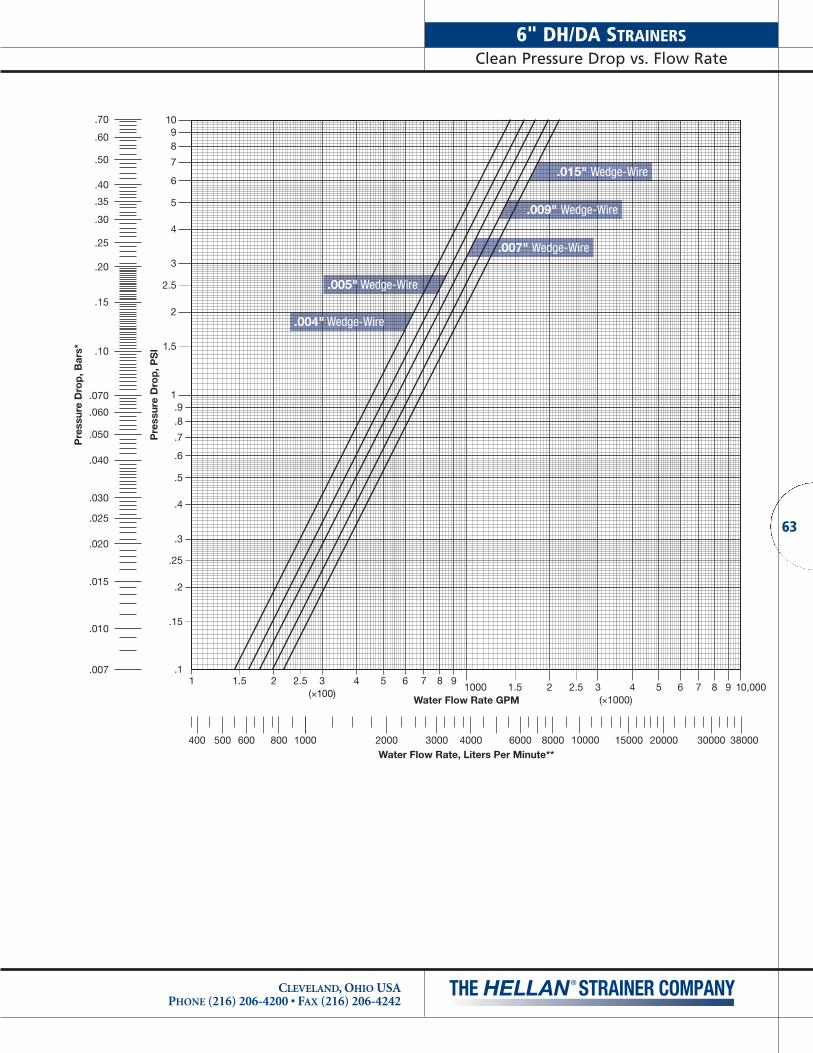
1 1.5 2 2.5 3 4 5 6 7 8 91000 1.5 2 2.5 3 4 5 6 7 8 9
Water Flow Rate GPM
Pre
ssur
e D
rop
, PS
I
1098
7
6
5
4
3
2.5
2
1.5
.015" Wedge-Wire
.009" Wedge-Wire
.007" Wedge-Wire
.005" Wedge-Wire
.004" Wedge-Wire
.70
Pre
ssur
e D
rop
, Bar
s*
.60
.50
.40
.35
.30
.25
.20
.15
.10
.070
.060
.050
.040
.030
.025
.020
.015
.010
.007
20001000 3000 6000 80004000 10000500 600 800400 15000 20000 30000 38000Water Flow Rate, Liters Per Minute**
(×100)(×1000)
10,000
1.9.8
.7
.6
.5
.4
.3
.25
.2
.15
.1
63
6" DH/DA STRAINERSClean Pressure Drop vs. Flow Rate
CLEVELAND, OHIO USAPHONE (216) 206-4200 • FAX (216) 206-4242
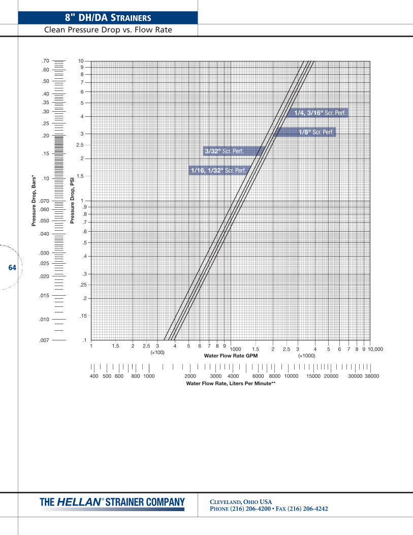
8" DH/DA STRAINERSClean Pressure Drop vs. Flow Rate
CLEVELAND, OHIO USAPHONE (216) 206-4200 • FAX (216) 206-4242
64
1 1.5 2 2.5 3 4 5 6 7 8 91000 1.5 2 2.5 3 4 5 6 7 8 9
Water Flow Rate GPM
Pre
ssur
e D
rop
, PS
I
1098
7
6
5
4
3
2.5
2
1.5
.70
Pre
ssur
e D
rop
, Bar
s*
.60
.50
.40
.35
.30
.25
.20
.15
.10
.070
.060
.050
.040
.030
.025
.020
.015
.010
.007
20001000 3000 6000 80004000 10000500 600 800400 15000 20000 30000 38000Water Flow Rate, Liters Per Minute**
1/4, 3/16" Scr. Perf.
1/8" Scr. Perf.
1/16, 1/32" Scr. Perf.
3/32" Scr. Perf.
(×100)(×1000)
10,000
1.9.8
.7
.6
.5
.4
.3
.25
.2
.15
.1

1 1.5 2 2.5 3 4 5 6 7 8 91000 1.5 2 2.5 3 4 5 6 7 8 9
Water Flow Rate GPM
Pre
ssur
e D
rop
, PS
I
1098
7
6
5
4
3
2.5
2
1.5
.015" Wedge-Wire
.009" Wedge-Wire
.007" Wedge-Wire
.005" Wedge-Wire
.004" Wedge-Wire
.70
Pre
ssur
e D
rop
, Bar
s*
.60
.50
.40
.35
.30
.25
.20
.15
.10
.070
.060
.050
.040
.030
.025
.020
.015
.010
.007
20001000 3000 6000 80004000 10000500 600 800400 15000 20000 30000 38000Water Flow Rate, Liters Per Minute**
(×100)(×1000)
10,000
1.9.8
.7
.6
.5
.4
.3
.25
.2
.15
.1
65
8" DH/DA STRAINERSClean Pressure Drop vs. Flow Rate
CLEVELAND, OHIO USAPHONE (216) 206-4200 • FAX (216) 206-4242
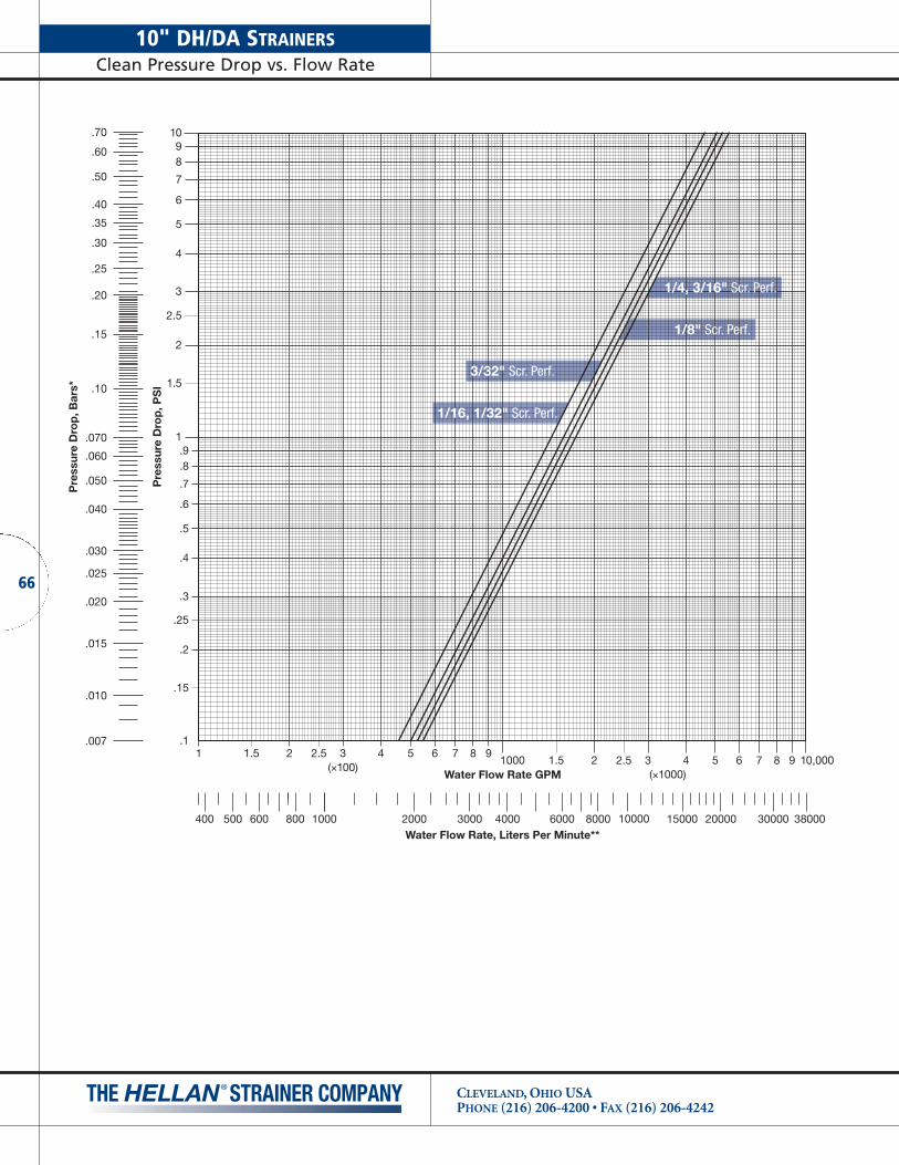
10" DH/DA STRAINERSClean Pressure Drop vs. Flow Rate
CLEVELAND, OHIO USAPHONE (216) 206-4200 • FAX (216) 206-4242
66
1 1.5 2 2.5 3 4 5 6 7 8 91000 1.5 2 2.5 3 4 5 6 7 8 9
Water Flow Rate GPM
Pre
ssur
e D
rop
, PS
I
1098
7
6
5
4
3
2.5
2
1.5
1/4, 3/16" Scr. Perf.
1/8" Scr. Perf.
1/16, 1/32" Scr. Perf.
3/32" Scr. Perf.
.70
Pre
ssur
e D
rop
, Bar
s*
.60
.50
.40
.35
.30
.25
.20
.15
.10
.070
.060
.050
.040
.030
.025
.020
.015
.010
.007
20001000 3000 6000 80004000 10000500 600 800400 15000 20000 30000 38000Water Flow Rate, Liters Per Minute**
(×100)(×1000)
10,000
1.9.8
.7
.6
.5
.4
.3
.25
.2
.15
.1

1 1.5 2 2.5 3 4 5 6 7 8 91000 1.5 2 2.5 3 4 5 6 7 8 9
Water Flow Rate GPM
Pre
ssur
e D
rop
, PS
I
1098
7
6
5
4
3
2.5
2
1.5
.015" Wedge-Wire
.009" Wedge-Wire
.007" Wedge-Wire
.005" Wedge-Wire
.004" Wedge-Wire
.70
Pre
ssur
e D
rop
, Bar
s*
.60
.50
.40
.35
.30
.25
.20
.15
.10
.070
.060
.050
.040
.030
.025
.020
.015
.010
.007
20001000 3000 6000 80004000 10000500 600 800400 15000 20000 30000 38000Water Flow Rate, Liters Per Minute**
(×100)(×1000)
10,000
1.9.8
.7
.6
.5
.4
.3
.25
.2
.15
.1
67
10" DH/DA STRAINERSClean Pressure Drop vs. Flow Rate
CLEVELAND, OHIO USAPHONE (216) 206-4200 • FAX (216) 206-4242

12" DH/DA STRAINERSClean Pressure Drop vs. Flow Rate
CLEVELAND, OHIO USAPHONE (216) 206-4200 • FAX (216) 206-4242
68
1 1.5 2 2.5 3 4 5 6 7 8 91000 1.5 2 2.5 3 4 5 6 7 8 9
Water Flow Rate GPM
Pre
ssur
e D
rop
, PS
I
1098
7
6
5
4
3
2.5
2
1.51/4, 3/16" Scr. Perf.
1/8" Scr. Perf.
1/16, 1/32" Scr. Perf.
3/32" Scr. Perf.
.70
Pre
ssur
e D
rop
, Bar
s*
.60
.50
.40
.35
.30
.25
.20
.15
.10
.070
.060
.050
.040
.030
.025
.020
.015
.010
.007
20001000 3000 6000 80004000 10000500 600 800400 15000 20000 30000 38000Water Flow Rate, Liters Per Minute**
(×100)(×1000)
10,000
1.9.8
.7
.6
.5
.4
.3
.25
.2
.15
.1
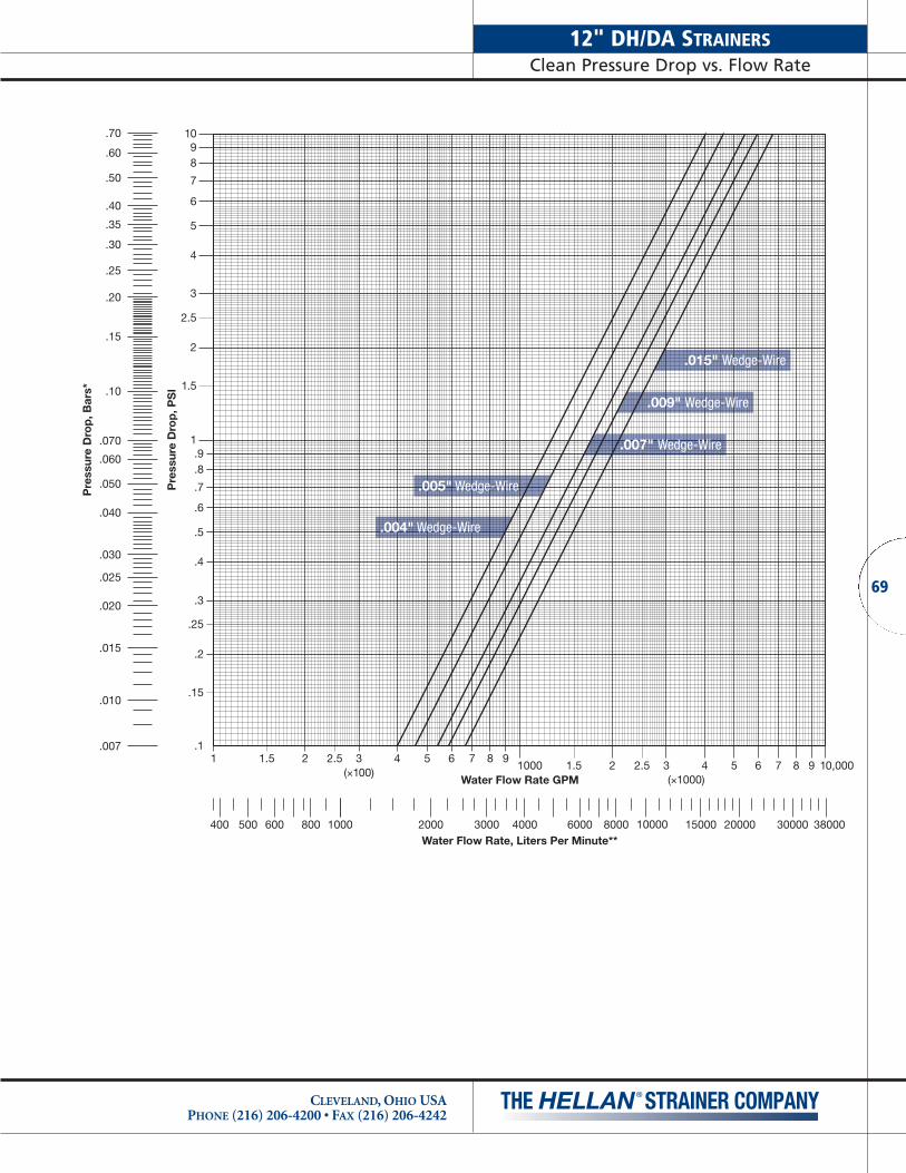
1 1.5 2 2.5 3 4 5 6 7 8 91000 1.5 2 2.5 3 4 5 6 7 8 9
Water Flow Rate GPM
Pre
ssur
e D
rop
, PS
I
1098
7
6
5
4
3
2.5
2
1.5
.015" Wedge-Wire
.009" Wedge-Wire
.007" Wedge-Wire
.005" Wedge-Wire
.004" Wedge-Wire
.70
Pre
ssur
e D
rop
, Bar
s*
.60
.50
.40
.35
.30
.25
.20
.15
.10
.070
.060
.050
.040
.030
.025
.020
.015
.010
.007
20001000 3000 6000 80004000 10000500 600 800400 15000 20000 30000 38000Water Flow Rate, Liters Per Minute**
(×100)(×1000)
10,000
1.9.8
.7
.6
.5
.4
.3
.25
.2
.15
.1
69
12" DH/DA STRAINERSClean Pressure Drop vs. Flow Rate
CLEVELAND, OHIO USAPHONE (216) 206-4200 • FAX (216) 206-4242

14" QH/QA STRAINERSClean Pressure Drop vs. Flow Rate
CLEVELAND, OHIO USAPHONE (216) 206-4200 • FAX (216) 206-4242
70
1 1.5 2 2.5 3 4 5 6 7 8 91000 1.5 2 2.5 3 4 5 6 7 8 9
Water Flow Rate GPM
Pre
ssur
e D
rop
, PS
I
1098
7
6
5
4
3
2.5
2
1.5
1/4, 3/16" Scr. Perf.
1/8" Scr. Perf.
1/16, 1/32" Scr. Perf.
3/32" Scr. Perf.
.70
Pre
ssur
e D
rop
, Bar
s*
.60
.50
.40
.35
.30
.25
.20
.15
.10
.070
.060
.050
.040
.030
.025
.020
.015
.010
.007
20001000 3000 6000 80004000 10000500 600 800400 15000 20000 30000 38000Water Flow Rate, Liters Per Minute**
(×100)(×1000)
10,000
1.9.8
.7
.6
.5
.4
.3
.25
.2
.15
.1
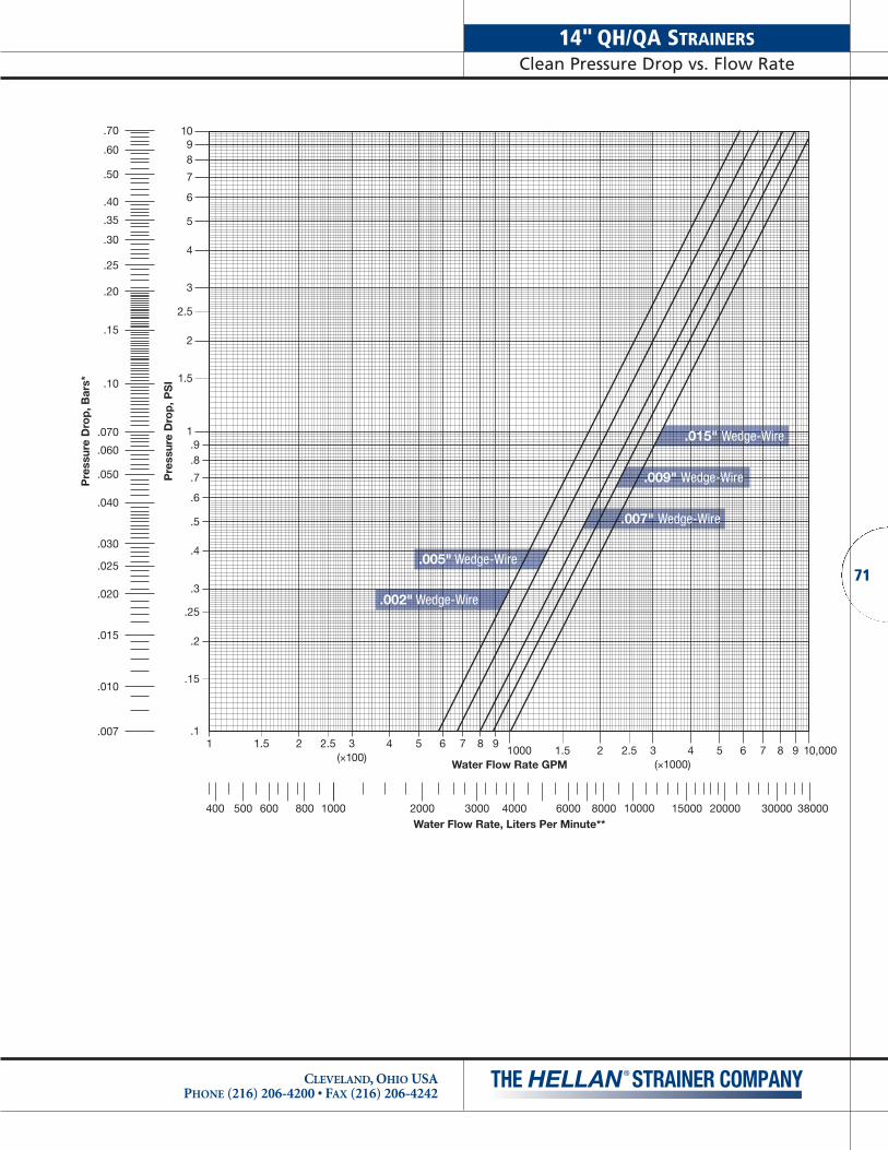
1 1.5 2 2.5 3 4 5 6 7 8 91000 1.5 2 2.5 3 4 5 6 7 8 9
Water Flow Rate GPM
Pre
ssur
e D
rop
, PS
I
1098
7
6
5
4
3
2.5
2
1.5
.015" Wedge-Wire
.009" Wedge-Wire
.007" Wedge-Wire
.005" Wedge-Wire
.002" Wedge-Wire
.70
Pre
ssur
e D
rop
, Bar
s*
.60
.50
.40
.35
.30
.25
.20
.15
.10
.070
.060
.050
.040
.030
.025
.020
.015
.010
.007
20001000 3000 6000 80004000 10000500 600 800400 15000 20000 30000 38000Water Flow Rate, Liters Per Minute**
(×100)(×1000)
10,000
1.9.8
.7
.6
.5
.4
.3
.25
.2
.15
.1
71
CLEVELAND, OHIO USAPHONE (216) 206-4200 • FAX (216) 206-4242
14" QH/QA STRAINERSClean Pressure Drop vs. Flow Rate
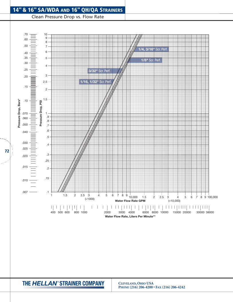
14"& 16" SA/WDA AND 16" QH/QA STRAINERSClean Pressure Drop vs. Flow Rate
CLEVELAND, OHIO USAPHONE (216) 206-4200 • FAX (216) 206-4242
72
1 1.5 2 2.5 3 4 5 6 7 8 910,000 1.5 2 2.5 3 4 5 6 7 8 9
Water Flow Rate GPM
rP
russer
D eI
SP ,
po
1098
7
6
5
4
3
2.5
2
1.5
1/4, 3/16" Scr. Perf.
1/8" Scr. Perf.
1/16, 1/32" Scr. Perf.
3/32" Scr. Perf.
.70
rP
ru sser
D e* sra
B ,p
o
.60
.50
.40
.35
.30
.25
.20
.15
.10
.070
.060
.050
.040
.030
.025
.020
.015
.010
.007
20001000 3000 6000 80004000 10000500 600 800400 15000 20000 30000 38000Water Flow Rate, Liters Per Minute**
(×1000)(×10,000)
100,000
1.9.8
.7
.6
.5
.4
.3
.25
.2
.15
.1

1 1.5 2 2.5 3 4 5 6 7 8 910,000 1.5 2 2.5 3 4 5 6 7 8 9
Water Flow Rate GPM
rP
russer
D eI
SP ,
po
1098
7
6
5
4
3
2.5
2
1.5
.015" Wedge-Wire
.009" Wedge-Wire
.007" Wedge-Wire
.005" Wedge-Wire
.004" Wedge-Wire
.70
rP
ru sser
D e* sra
B ,p
o
.60
.50
.40
.35
.30
.25
.20
.15
.10
.070
.060
.050
.040
.030
.025
.020
.015
.010
.007
20001000 3000 6000 80004000 10000500 600 800400 15000 20000 30000 38000Water Flow Rate, Liters Per Minute**
(×1000)(×10,000)
100,000
1.9.8
.7
.6
.5
.4
.3
.25
.2
.15
.1
73
14"& 16" SA/WDA AND 16" QH/QA STRAINERSClean Pressure Drop vs. Flow Rate
CLEVELAND, OHIO USAPHONE (216) 206-4200 • FAX (216) 206-4242

20" HH/AH AND 20" WDA STRAINERSClean Pressure Drop vs. Flow Rate
CLEVELAND, OHIO USAPHONE (216) 206-4200 • FAX (216) 206-4242
74
1 1.5 2 2.5 3 4 5 6 7 8 910,000 1.5 2 2.5 3 4 5 6 7 8 9
Water Flow Rate GPM
Pre
ssur
e D
rop
, PS
I
1098
7
6
5
4
3
2.5
2
1.5
1/4, 3/16" Scr. Perf.
1/8" Scr. Perf.
1/16, 1/32" Scr. Perf.
3/32" Scr. Perf.
.70
Pre
ssur
e D
rop
, Bar
s*
.60
.50
.40
.35
.30
.25
.20
.15
.10
.070
.060
.050
.040
.030
.025
.020
.015
.010
.007
2000010000 30000 60000 8000040000 1000006000 80004000 150000 200000 300000 380000Water Flow Rate, Liters Per Minute**
(×1000)(×10,000)
100,000
1.9.8
.7
.6
.5
.4
.3
.25
.2
.15
.1

1 1.5 2 2.5 3 4 5 6 7 8 910,000 1.5 2 2.5 3 4 5 6 7 8 9
Water Flow Rate GPM
Pre
ssur
e D
rop
, PS
I
1098
7
6
5
4
3
2.5
2
1.5
.70
Pre
ssur
e D
rop
, Bar
s*
.60
.50
.40
.35
.30
.25
.20
.15
.10
.070
.060
.050
.040
.030
.025
.020
.015
.010
.007
2000010000 30000 60000 8000040000 1000006000 80004000 150000 200000 300000 380000Water Flow Rate, Liters Per Minute**
(×1000)(×10,000)
100,000
1.9.8
.7
.6
.5
.4
.3
.25
.2
.15
.1
.015" Wedge-Wire
.009" Wedge-Wire
.007" Wedge-Wire
.005" Wedge-Wire
.004" Wedge-Wire
75
20" HH/AH AND 20" WDA STRAINERSClean Pressure Drop vs. Flow Rate
CLEVELAND, OHIO USAPHONE (216) 206-4200 • FAX (216) 206-4242

24" WDA STRAINERSClean Pressure Drop vs. Flow Rate
CLEVELAND, OHIO USAPHONE (216) 206-4200 • FAX (216) 206-4242
76
1 1.5 2 2.5 3 4 5 6 7 8 910,000 1.5 2 2.5 3 4 5 6 7 8 9
Water Flow Rate GPM
Pre
ssur
e D
rop
, PS
I
1098
7
6
5
4
3
2.5
2
1.5
1/4, 3/16" Scr. Perf.
1/8" Scr. Perf.
1/16, 1/32" Scr. Perf.
3/32" Scr. Perf.
.70
Pre
ssur
e D
rop
, Bar
s*
.60
.50
.40
.35
.30
.25
.20
.15
.10
.070
.060
.050
.040
.030
.025
.020
.015
.010
.007
2000010000 30000 60000 8000040000 1000006000 80004000 150000 200000 300000 380000Water Flow Rate, Liters Per Minute**
(×1000)(×10,000)
100,000
1.9.8
.7
.6
.5
.4
.3
.25
.2
.15
.1

1 1.5 2 2.5 3 4 5 6 7 8 910,000 1.5 2 2.5 3 4 5 6 7 8 9
Water Flow Rate GPM
Pre
ssur
e D
rop
, PS
I
1098
7
6
5
4
3
2.5
2
1.5
.70
Pre
ssur
e D
rop
, Bar
s*
.60
.50
.40
.35
.30
.25
.20
.15
.10
.070
.060
.050
.040
.030
.025
.020
.015
.010
.007
2000010000 30000 60000 8000040000 1000006000 80004000 150000 200000 300000 380000Water Flow Rate, Liters Per Minute**
.015" Wedge-Wire
.009" Wedge-Wire
.007" Wedge-Wire
.005" Wedge-Wire
.004" Wedge-Wire
(×1000)(×10,000)
100,000
1.9.8
.7
.6
.5
.4
.3
.25
.2
.15
.1
77
24" WDA STRAINERSClean Pressure Drop vs. Flow Rate
CLEVELAND, OHIO USAPHONE (216) 206-4200 • FAX (216) 206-4242
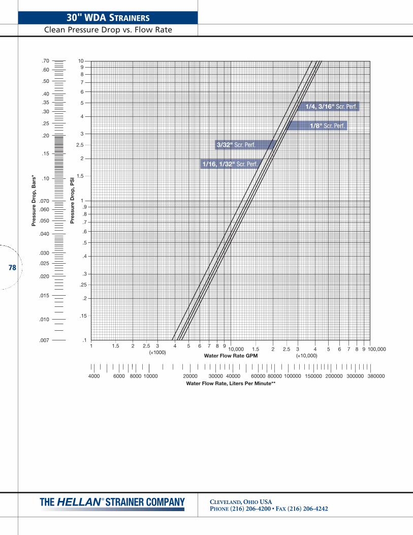
30" WDA STRAINERSClean Pressure Drop vs. Flow Rate
CLEVELAND, OHIO USAPHONE (216) 206-4200 • FAX (216) 206-4242
78
1 1.5 2 2.5 3 4 5 6 7 8 910,000 1.5 2 2.5 3 4 5 6 7 8 9
Water Flow Rate GPM
Pre
ssur
e D
rop
, PS
I
1098
7
6
5
4
3
2.5
2
1.5
1/4, 3/16" Scr. Perf.
1/8" Scr. Perf.
1/16, 1/32" Scr. Perf.
3/32" Scr. Perf.
.70
Pre
ssur
e D
rop
, Bar
s*
.60
.50
.40
.35
.30
.25
.20
.15
.10
.070
.060
.050
.040
.030
.025
.020
.015
.010
.007
2000010000 30000 60000 8000040000 1000006000 80004000 150000 200000 300000 380000Water Flow Rate, Liters Per Minute**
(×1000)(×10,000)
100,000
1.9.8
.7
.6
.5
.4
.3
.25
.2
.15
.1

1 1.5 2 2.5 3 4 5 6 7 8 910,000 1.5 2 2.5 3 4 5 6 7 8 9
Water Flow Rate GPM
Pre
ssur
e D
rop
, PS
I
1098
7
6
5
4
3
2.5
2
1.5
.70
Pre
ssur
e D
rop
, Bar
s*
.60
.50
.40
.35
.30
.25
.20
.15
.10
.070
.060
.050
.040
.030
.025
.020
.015
.010
.007
2000010000 30000 60000 8000040000 1000006000 80004000 150000 200000 300000 380000Water Flow Rate, Liters Per Minute**
.015" Wedge-Wire
.009" Wedge-Wire
.007" Wedge-Wire
.005" Wedge-Wire
.004" Wedge-Wire
(×1000)(×10,000)
100,000
1.9.8
.7
.6
.5
.4
.3
.25
.2
.15
.1
79
30" WDA STRAINERSClean Pressure Drop vs. Flow Rate
CLEVELAND, OHIO USAPHONE (216) 206-4200 • FAX (216) 206-4242
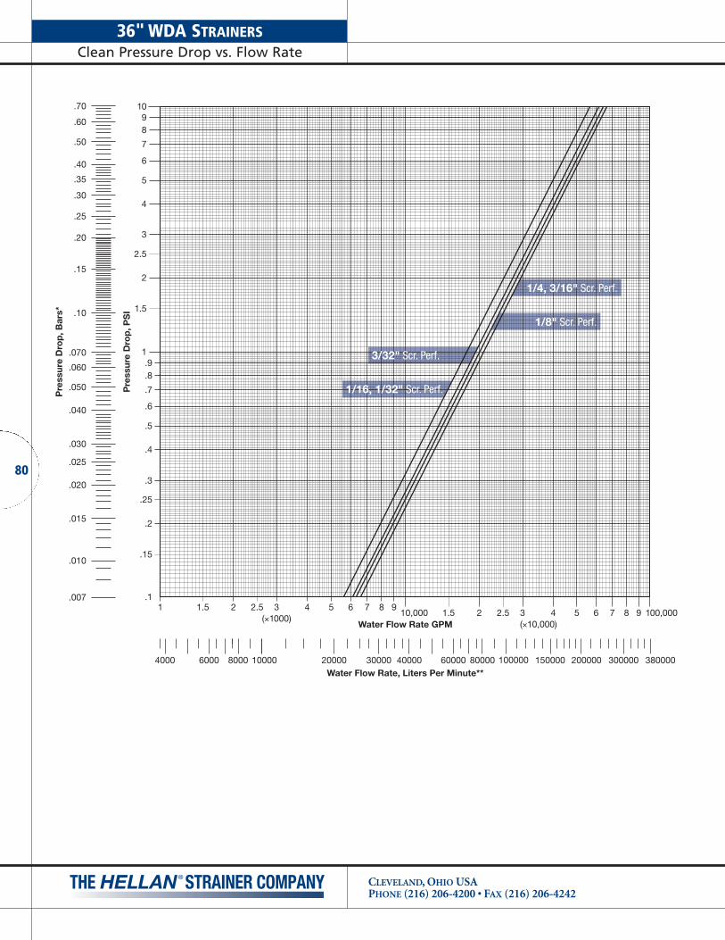
36" WDA STRAINERSClean Pressure Drop vs. Flow Rate
CLEVELAND, OHIO USAPHONE (216) 206-4200 • FAX (216) 206-4242
80
1 1.5 2 2.5 3 4 5 6 7 8 910,000 1.5 2 2.5 3 4 5 6 7 8 9
Water Flow Rate GPM
Pre
ssur
e D
rop
, PS
I
1098
7
6
5
4
3
2.5
2
1.5
1/4, 3/16" Scr. Perf.
1/8" Scr. Perf.
1/16, 1/32" Scr. Perf.
3/32" Scr. Perf.
.70
Pre
ssur
e D
rop
, Bar
s*
.60
.50
.40
.35
.30
.25
.20
.15
.10
.070
.060
.050
.040
.030
.025
.020
.015
.010
.007
2000010000 30000 60000 8000040000 1000006000 80004000 150000 200000 300000 380000Water Flow Rate, Liters Per Minute**
(×1000)(×10,000)
100,000
1.9.8
.7
.6
.5
.4
.3
.25
.2
.15
.1

1 1.5 2 2.5 3 4 5 6 7 8 910,000 1.5 2 2.5 3 4 5 6 7 8 9
Water Flow Rate GPM
Pre
ssur
e D
rop
, PS
I
1098
7
6
5
4
3
2.5
2
1.5
.70
Pre
ssur
e D
rop
, Bar
s*
.60
.50
.40
.35
.30
.25
.20
.15
.10
.070
.060
.050
.040
.030
.025
.020
.015
.010
.007
2000010000 30000 60000 8000040000 1000006000 80004000 150000 200000 300000 380000Water Flow Rate, Liters Per Minute**
.015" Wedge-Wire
.009" Wedge-Wire
.007" Wedge-Wire
.005" Wedge-Wire
.004" Wedge-Wire
(×1000)(×10,000)
100,000
1.9.8
.7
.6
.5
.4
.3
.25
.2
.15
.1
81
36" WDA STRAINERSClean Pressure Drop vs. Flow Rate
CLEVELAND, OHIO USAPHONE (216) 206-4200 • FAX (216) 206-4242

SPECIFYING A MODEL NUMBER
CLEVELAND, OHIO USAPHONE (216) 206-4200 • FAX (216) 206-4242
82
CHART A – STRAINER SIZE
Flow Rate Pipe Part No.(GPM) Size Code
95 1-1/2" 015
95 2" 020
160 2-1/2" 025
235 3" 030
360 4" 040
880 6" 060
1450 8" 080
2075 10" 100
2750 12" 120
4100 14" 140
5300 16" 160
8250 20" 200
10650 24" 240
16650 30" 300
24000 36" 360
(See page 11-12 for information on selecting size.)
CHART B – FLANGE TYPE
Flange Available Part No.Type Materials Code
Class 125 Flat Face Cast Iron 1
Class 250 Raised Face Cast iron 2
Class 150 Steel, Stainless Steel and Bronze 3
Class 300 Raised Face Steel, Stainless Steel and Bronze 4
Class 125 Flat Face Ductile Iron S
Class 125LW Carbon Steel Weldment SW
Note: Contact the factory for information on flange types not listed above.
(See page 14 for information on flange selection.)
CHART C – BODY STYLE
Body Part No.Style CodeAngled Flow, Single Screen A
In-Line Flow, Dual Screens D
In-Line Flow, Quad Screens Q
In-Line Flow, Six Screens H
(See pages 8-10 for information on availability of strainersin various types of operation methods.)
CHART D – METHOD OF OPERATION
Method of Part No.Operation Code
Manual (Handwheel) H
Automatic A
Note: Strainers with motorized option must be ordered with appropriate control panel.
See information on specifying control panel below.
(See pages 8-10 for information on availability of strainersin various types of operation methods.)
CHART E – MOTOR SPECIFICATIONS FORAUTOMATIC STRAINERS
(For Manual Strainers, enter a “-” in this portion)
Motor Part No.Option Code
230/460 VAC 50/60HZ, 3PH, TEFC 1
115/230 VAC 50/60HZ, 1PH, TEFC 2
230/460 VAC 50/60HZ, 3PH, NEMA 7 3
115/230 VAC 50/60HZ, 1PH, NEMA 7 4
Note: Contact the factory for information on motor options not listed above.
(See pages 18 and 19 for information on motor options.)
CHART F – SCREEN MATERIAL
Screen Part No.Material Code
Monel Screen, All Parts 3
316 Screen, Cast Iron Hub,Cast Iron Center Ring, Bronze End Ring 4
316 Stainless Steel, All Parts 5
Note: Contact the factory for information on screen materials not listed above.
(See page 13 for information on screen material options.)
A model number for a Hellan Strainer may be specified by utilizing the charts and information below:
SAMPLE MODEL NUMBER
0 8 0 1 D H - 4 0 4 0 0
Basic Construction Materials (Chart H)Screen Opening Size (Chart G)Screen Material (Chart F)Motor Type (Chart E)Operation (Chart D)Body Style (Chart C)Flange Type (Chart B)Size (Chart A)
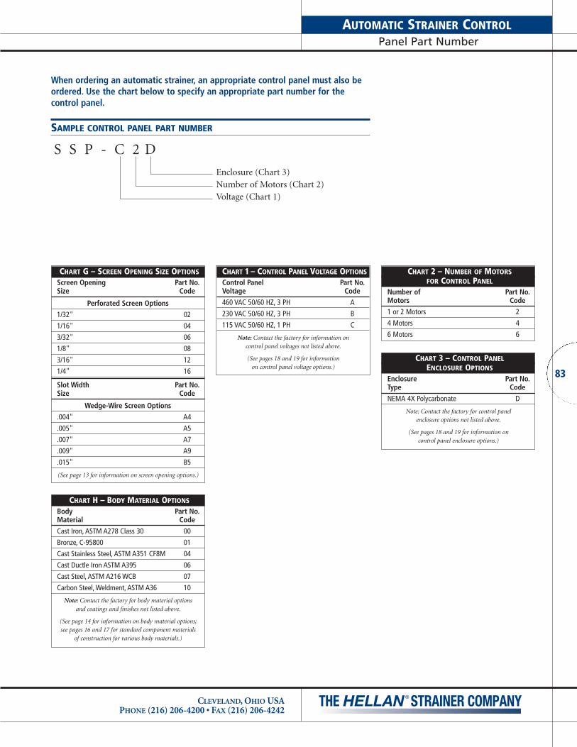
83
AUTOMATIC STRAINER CONTROLPanel Part Number
CLEVELAND, OHIO USAPHONE (216) 206-4200 • FAX (216) 206-4242
CHART G – SCREEN OPENING SIZE OPTIONS
Screen Opening Part No.Size Code
Perforated Screen Options
1/32" 02
1/16" 04
3/32" 06
1/8" 08
3/16" 12
1/4" 16
Slot Width Part No.Size Code
Wedge-Wire Screen Options
.004" A4
.005" A5
.007" A7
.009" A9
.015" B5
(See page 13 for information on screen opening options.)
CHART H – BODY MATERIAL OPTIONS
Body Part No.Material Code
Cast Iron, ASTM A278 Class 30 00
Bronze, C-95800 01
Cast Stainless Steel, ASTM A351 CF8M 04
Cast Ductle Iron ASTM A395 06
Cast Steel, ASTM A216 WCB 07
Carbon Steel, Weldment, ASTM A36 10
Note: Contact the factory for body material options and coatings and finishes not listed above.
(See page 14 for information on body material options; see pages 16 and 17 for standard component materials
of construction for various body materials.)
When ordering an automatic strainer, an appropriate control panel must also beordered. Use the chart below to specify an appropriate part number for the control panel.
SAMPLE CONTROL PANEL PART NUMBER
S S P - C 2 D
Enclosure (Chart 3)Number of Motors (Chart 2)Voltage (Chart 1)
CHART 1 – CONTROL PANEL VOLTAGE OPTIONS
Control Panel Part No.Voltage Code
460 VAC 50/60 HZ, 3 PH A
230 VAC 50/60 HZ, 3 PH B
115 VAC 50/60 HZ, 1 PH C
Note: Contact the factory for information on control panel voltages not listed above.
(See pages 18 and 19 for information on control panel voltage options.)
CHART 2 – NUMBER OF MOTORSFOR CONTROL PANEL
Number of Part No.Motors Code
1 or 2 Motors 2
4 Motors 4
6 Motors 6
CHART 3 – CONTROL PANELENCLOSURE OPTIONS
Enclosure Part No.Type Code
NEMA 4X Polycarbonate D
Note: Contact the factory for control panel enclosure options not listed above.
(See pages 18 and 19 for information on control panel enclosure options.)

SAMPLES OF STANDARD SPECIFICATION
CLEVELAND, OHIO USAPHONE (216) 206-4200 • FAX (216) 206-4242
84
HELLAN MANUAL STRAINERS
The strainer shall be a _____" manual type employing _____cylindrical straining screens of the peripheral inflow design.The straining screens shall have _____" round perforations orwedgewire _____" slots and be of Type 316 Stainless Steelmaterial. Adjustable rigid scraper bars or brushes shall bemounted adjacent to the screens to accommodate scrapping of accumulated solids from the screens when the strainingscreens are rotated by means of a handwheel during a cleaningcycle. Removal of an inspection cover shall give access to thescraper bar or brush for inspection and adjustment and shallnot require the disassembly of the strainer to accomplish those tasks.
The strainer shall also have a sump for storage of strainedsolids. A flush valve installed on the sump by others shall beused to flush solids from the strainer during cleaning cycles.
The strainer body shall be of cast or fabricated steel ASTM _____ and have integral, in-line _____" inlet, and outlet flanges. Flanges shall be ANSI class _____.
The assembled strainer shall be hydrostatically pressure testedto 1-1/2" times the maximum allowable working pressure for aperiod of 10 minutes.
The assembled strainer shall be painted with a high-qualityalkyd machinery enamel (gray color), Glidden Glid-GuardAlkyd Industrial Enamel No. 4550 Series.
An adjustable pressure differential switch (optional) shall bemounted on the strainer and shall be used to initiate an alarmif the pressure drop reaches a predetermined set point.
The strainer shall be a Hellan Strainer manufactured by TheHellan Strainer Company, Cleveland, Ohio.
HELLAN AUTOMATIC STRAINERS
The strainer shall be a _____" automatic type employing_____ cylindrical straining screens of the peripheral inflowdesign. The straining screens shall have _____" round per-forations or wedgewire _____" slots and be of Type 316Stainless Steel material. Adjustable rigid scraper bars or brushes shall be mounted adjacent to the screens to accom-modate scraping of accumulated solids from the screens whenthe straining screens are rotated with an electric motor andsuitable gear reduction. Each motor shall be 1/3 to 2 horse-power (as required) _____ Volt, _____ Ph, _____ Hz, 1.15 SFClass “F” Insulation, TEFC, 56C-Face, Footless. Removal of aninspection cover shall give access to the scraper bar or brushfor inspection and adjustment and shall not require the disassembly of the strainer to accomplish those tasks.
The strainer shall also have a sump for storage of strainedsolids. One 1-1/4" ball valve on 1-1/2" & 2" strainers, one 1-1/2" ball valve on 2-1/2" & 3" strainers, two 2" ball valves on14" and 16" strainers, two 3" ball valves on 20" and 24" strainers and two 4” ball valves on 30" and 36" strainers.
The strainer body shall be of cast or fabricated _____ con-struction per ASTM _____ and have integral, in-line _____"inlet, and outlet flanges. Flanges shall be ANSI class _____.
The assembled strainer shall be hydrostatically pressure testedto 1-1/2 times the maximum allowable working pressure for aperiod of 10 minutes.
The assembled (cast construction) strainer shall be paintedwith a high-quality alkyd machinery enamel (gray color),Glidden Glid-Guard Alkyd Industrial Enamel No. 4550 Series.Assembled strainer of fabricated construction will be paintedwith a high-quality machinery gray, Glidden No. 4208 Series.
An electric control panel furnished by The Hellan StrainerCompany shall control the strainer cleaning cycle. The panelshall include all motor starters, control relays, fuse and over-load protection, control transformer, operation lights, etc., andshall be mounted in a NEMA 4X wall mounted polycarbonateenclosure equipped with a door disconnect switch. The controlpanel shall conform to current NEMA, NEC, and OSHA codesand regulations.
The strainer control panel shall be equipped with a pro-grammable solid state timer to initiate cleaning cycles at predetermined intervals, a hand/off/automatic selector switch,and a push-button for manual starting. An adjustable cycleduration timer shall also be furnished to allow for control ofthe cleaning cycle duration. An adjustable pressure differentialswitch shall be mounted on the strainer and shall be used toinitiate a cleaning cycle if the pressure drop reaches a predetermined set point.
The strainer shall be a Hellan Strainer manufactured by The Hellan Strainer Company, Cleveland, Ohio.
For assistance in selecting a strainer, or specifying a model,contact the Hellan sales department at 1-888-4-HELLAN.

85
NOTES
CLEVELAND, OHIO USAPHONE (216) 206-4200 • FAX (216) 206-4242
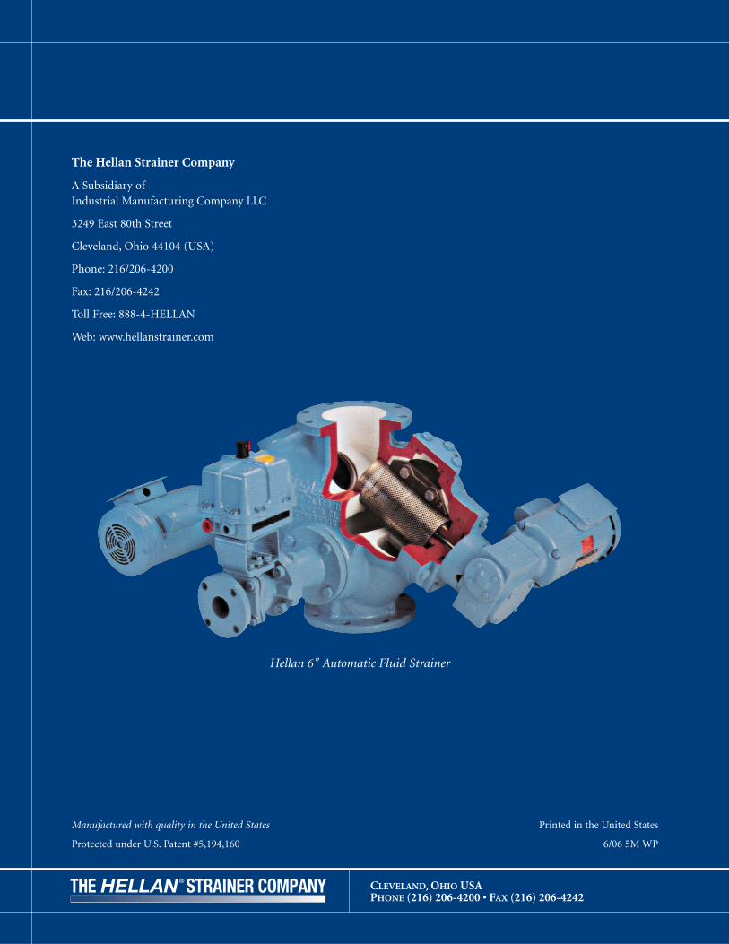
CLEVELAND, OHIO USAPHONE (216) 206-4200 • FAX (216) 206-4242
The Hellan Strainer Company
A Subsidiary ofIndustrial Manufacturing Company LLC
3249 East 80th Street
Cleveland, Ohio 44104 (USA)
Phone: 216/206-4200
Fax: 216/206-4242
Toll Free: 888-4-HELLAN
Web: www.hellanstrainer.com
Manufactured with quality in the United States
Protected under U.S. Patent #5,194,160
Printed in the United States
6/06 5M WP
Hellan 6" Automatic Fluid Strainer