1
SUPPLEMENT-1File this supplement with the service manual.
SERVICE MANUAL
Subject: 1. CORRECTION2. ADDITION OF PARTS AND REMOVE PAGE
HCD-EX1US Model
Canadian ModelAEP Model
UK ModelE Model
Australian ModelTourist Model
1. CORRECTION! : indicates correct portion
PAGE
7
INCORRECT CORRECT
(ECN-TAC02395, TAC02707)
Note: Page 39 is removed.
2
Front Panel
%
Remote
18 DSG button @19 REPEAT button @
Front Panel
2
Remote
18 REPEAT button19 DSG button
2
PAGE INCORRECT CORRECT
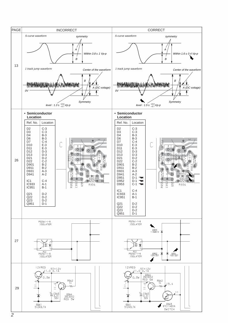
26
29
Ref. No. Location
D2 C-3D3 C-3D4 B-3D6 B-3D7 C-4D10 E-3D11 E-3D12 D-3D13 D-3D21 D-2D22 C-2D901 B-2D911 B-2D931 A-3D941 A-2
IC1 C-4IC933 A-1IC951 B-1
Q21 D-2Q22 D-2Q23 D-2Q951 D-1
• SemiconductorLocation
Ref. No. Location
D2 C-3D3 C-3D4 B-3D6 B-3D7 C-4D10 E-3D11 E-3D12 D-3D13 D-3D21 D-2D22 C-2D901 B-2D911 B-2D931 A-3D941 A-2D951 D-1D952 D-1D953 C-1
IC1 C-4IC933 A-1IC951 B-1
Q21 D-2Q22 D-2Q23 D-2Q951 D-1
• SemiconductorLocation
@@@
^
%
#
#
27
$$
#
13
symmetry
A
B
Within 3.8 ± 1 Vp-p
symmetry
A
B
Within 1.6 ± 0.4 Vp-p
$
S-curve waveform
1 track jump waveform
S-curve waveform
1 track jump waveform
0V
Center of the waveform
B
Symmetry
A (DC voitage)
level : 1.3 ± Vp-p+0.6–0.7
0V
Center of the waveform
B
Symmetry
A (DC voitage)
level : 1.5 ± Vp-p+0.5–0.7
%

3
PAGE INCORRECT CORRECT
45
42
46
1-675-407-11 REG BOARD**********
< TRANSISTOR >
MISCELLANEOUS*************
153 8-820-087-11 OPTICAL PICK-UP KSS-770A/S-N1155 1-763-381-11 MOTOR, DC
158 1-960-065-11 HARNESS160 1-791-698-11 WIRE (FLAT TYPE) (16 CORE)
1-675-407-11 REG BOARD**********
< TRANSISTOR >
Q963 8-729-900-53 TRANSISTOR DTC114EKA-T146 @
MISCELLANEOUS*************
127 1-791-698-11 WIRE (FLAT TYPE) (16 CORE) @@@
@@
M351 X-4952-498-1 MOTOR ASSY @
Ref. No. Part No. Description Remark
A-4426-742-A MAIN BOARD, COMPLETE (US,CND)***********
A-4426-752-A MAIN BOARD, COMPLETE (EXCEPT US,CND)***********
< IC >
IC701 8-759-643-70 IC uPD780306GF-024-3BA
Ref. No. Part No. Description Remark
A-4426-742-A MAIN BOARD, COMPLETE (US,CND)***********
A-4426-752-A MAIN BOARD, COMPLETE (EXCEPT US,CND)***********
< IC >
IC701 8-759-667-65 IC uPD78P0308GF-028-3BA$ $
A-4426-744-A POWER BOARD, COMPLETE (US,CND)************
A-4426-753-A POWER BOARD, COMPLETE (EXCEPT US,CND)************
< COIL >
L1 1-419-528-11 COIL, COMON MODE CHOKE$
A-4426-744-A POWER BOARD, COMPLETE (US,CND)************
A-4426-753-A POWER BOARD, COMPLETE (EXCEPT US,CND)************
< COIL >
L1 1-419-341-11 COIL, COMON MODE CHOKE

4
SECTION 1SERVICING NOTE
2. ADDITION OF PARTS AND REMOVE PAGE
Page 4
ADJUSTMENT OF CAM PHASE
Note : Set the slider (1) in this location before inserting the cam.
STEP 4Bend the slider (2) slightly in the arrow direction and attach it by inserting it in the grooves of the guides (L) and (R).
Absorber Absorber
SW lever SW lever
Boss
Cam
Slider (3)
Screw(BVTP2.6x8)
Screw(PTTWH2.6x8)
Screw(BVTP2.6x8)
Groove of slider (3)
Hole of slider (3)
Guide (L)
Boss (Four point)
Guide (R)
Groove
Groove
Slider (2)
Lever (1)
Lever (1)
Mecha cover
CamBossBoss
Boss
Cam
Boss
Insert the cam so that the boss touches the SW lever at the left shown in the figure.
Rotate the cam in the arrow direction, and adjust thephase until the boss touches the SW lever shown inthe figure.
With the phase adjusted, attach the parts using the following procedure.
STEP1Insert the boss of the slider (3) in the groove of the cam.
STEP2Set the mecha cover to the groove on the slider (3) and attach.
STEP3Insert the boss of the lever (1) in the hole of the slider (3) and attach.
Insert these in the groove first.
Insert these in the groove afterwards.
5
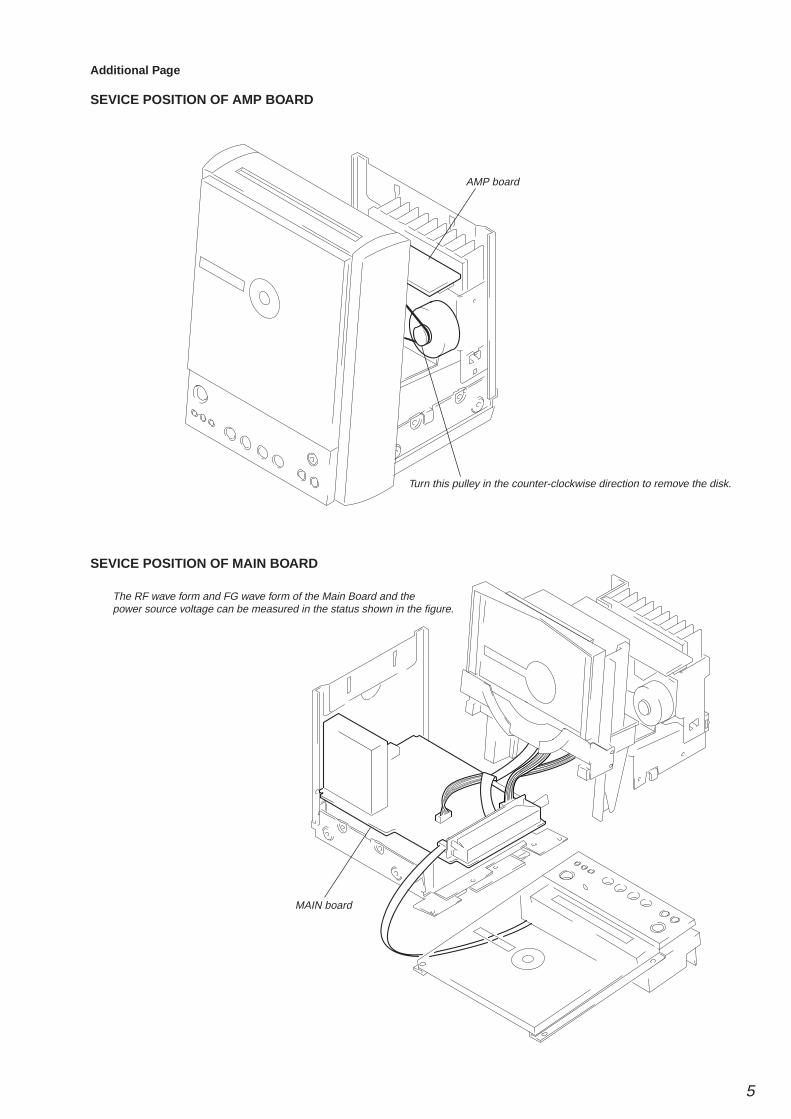
Additional Page
SEVICE POSITION OF AMP BOARD
Turn this pulley in the counter-clockwise direction to remove the disk.
AMP board
MAIN board
The RF wave form and FG wave form of the Main Board and thepower source voltage can be measured in the status shown in the figure.
SEVICE POSITION OF MAIN BOARD
6
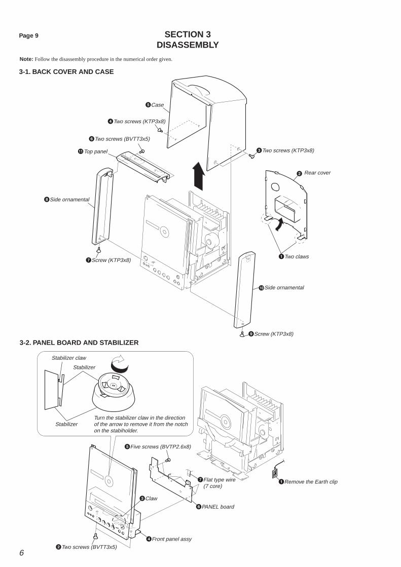
SECTION 3DISASSEMBLY
Page 9
3-1. BACK COVER AND CASE
Note: Follow the disassembly procedure in the numerical order given.
3-2. PANEL BOARD AND STABILIZER
1
2
3
4
5
6
7
8
0
qaÁ
Two claws
Two screws (KTP3x8)
Two screws (KTP3x8)
Screw (KTP3x8)
Screw (KTP3x8)
Two screws (BVTT3x5)
Side ornamental
Side ornamental
Rear cover
Case
Top panel
9
1
3
2
4
7
5
6
Remove the Earth clip
Two screws (BVTT3x5)
Front panel assy
PANEL board
Claw
Flat type wire (7 core)
Five screws (BVTP2.6x8)
Stabilizer
Stabilizer
Stabilizer claw
Turn the stabilizer claw in the directionof the arrow to remove it from the notchon the stabiholder.
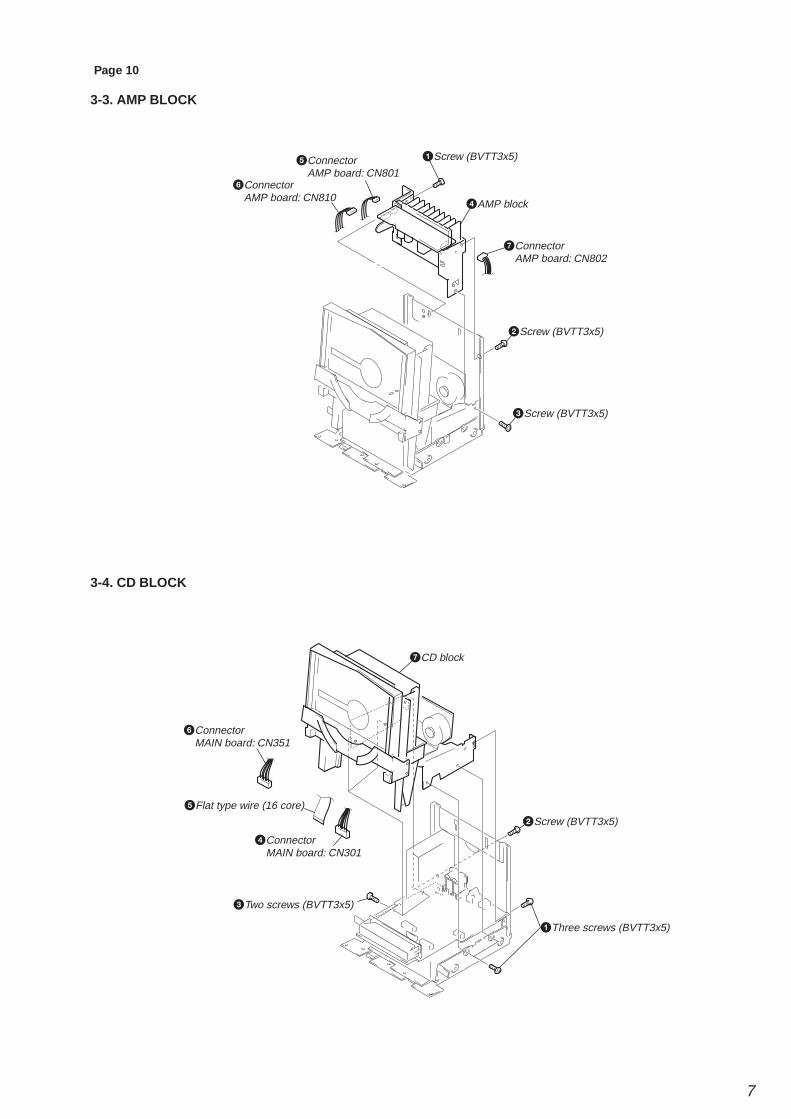
7
3-4. CD BLOCK
3-3. AMP BLOCK
Page 10
ConnectorAMP board: CN801
Screw (BVTT3x5)
AMP block
Screw (BVTT3x5)
Screw (BVTT3x5)
ConnectorAMP board: CN810
ConnectorAMP board: CN802
5
6
7
1
2
3
4
Connector MAIN board: CN351
Flat type wire (16 core)
Connector MAIN board: CN301
1
2
3
4
5
6
7
Three screws (BVTT3x5)
Screw (BVTT3x5)
Two screws (BVTT3x5)
CD block
8
3-5. MOTOR ASSY AND CAM
Note: Adjustment of the phase is required in assembly.Refer to"Section 1. Servicing Note" for details.
Page 11
Slider (3)
Slider (2)
Boss
Boss
Diskholder
Lever (1)
Mecha cover
Motor assy
SW cam
Two screws (BVTT3x5)
Two screws (BVTP2.6x8)
Two screws (BVTP2.6x8)
Three screws (BVTT3x5)
Bracket(CDM)
Two screws (BVTP2.6x8)
Two screws (BVTP2.6x8)
Screws (BTP2.6x8)
Screws (PTPWH2.6x6)
Cam
7
6
8
9
0
qaÁ
qs
qdqf
qg
qh
qj
3
4
5
Set the main unit in EJECT status then use the following procedureto remove it with the slider (2) and the diskholder assembled.
1 Remove the boss of the slider (2) from the grooves of the guides (L) and (R).
2 Bend the slider (2) in the direction shown in the figure to take it from the lever (1) and remove it in the upwards direction.
1
2
3
4
5
6
7
8
9
0
qs
qd
qf
qg
qaÁ
Two screws (BVTP2.6x8)
Two screws (BVTP2.6x8)
Guide (L)
Guide (R)
Slider (4)
Slider (4)
Slider (1)
Two screws (PTPWH2.6)
Screws (PTPWH2.6)
Two screws (PTPWH2.6)
Two screws (PTPWH2.6)Coil spring
Coil spring
BU holder
Pick up assy
3-6. BASE UNIT
9
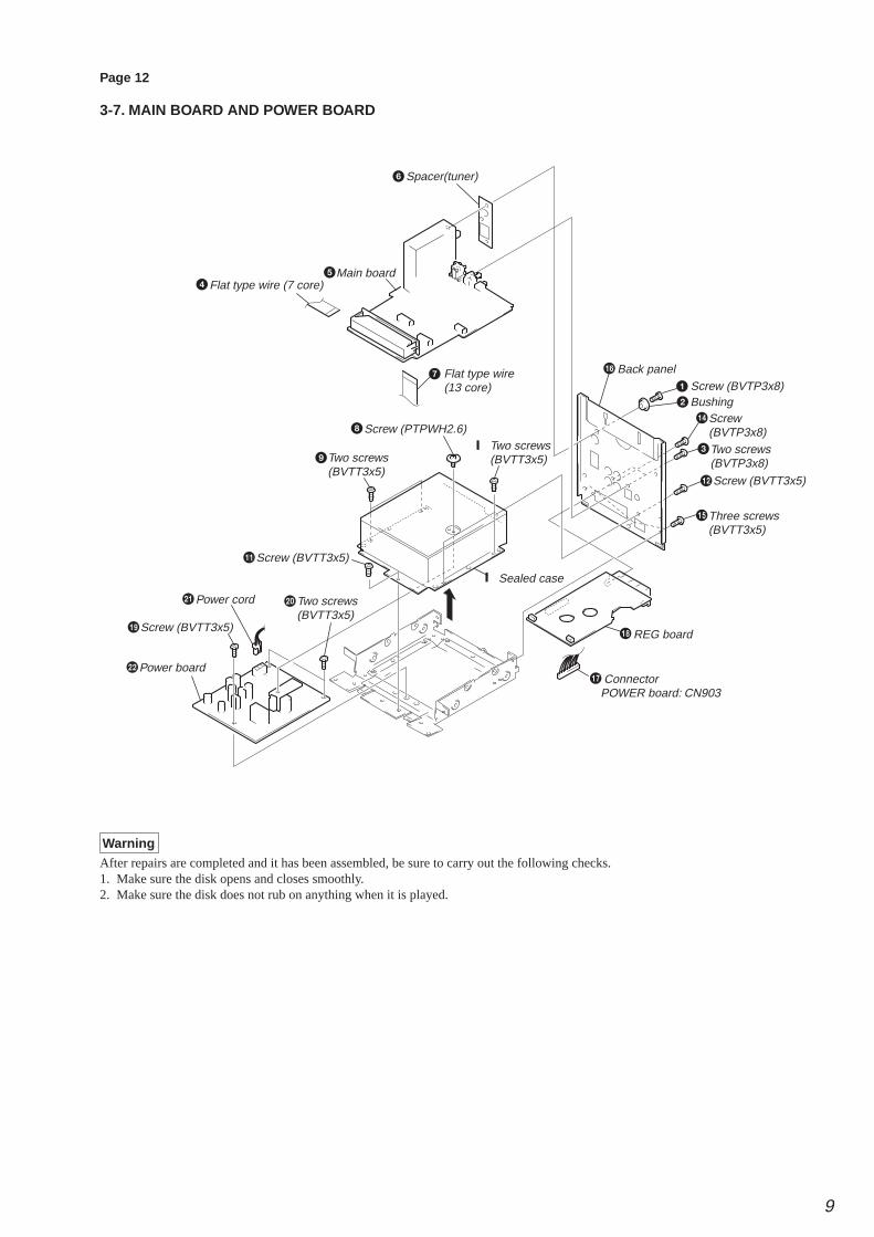
Page 12
3-7. MAIN BOARD AND POWER BOARD
WarningAfter repairs are completed and it has been assembled, be sure to carry out the following checks.1. Make sure the disk opens and closes smoothly.2. Make sure the disk does not rub on anything when it is played.
Two screws (BVTT3x5)
Two screws (BVTP3x8)
Screw (BVTP3x8)
Three screws (BVTT3x5)
Two screws (BVTT3x5)
Screw (PTPWH2.6)
Screw (BVTP3x8)
Screw (BVTT3x5)
Screw (BVTT3x5)
Main board
Power board
Power cord
REG board
Connector POWER board: CN903
Back panel
Bushing
Two screws (BVTT3x5)
Screw (BVTT3x5)
Sealed case
Spacer(tuner)
Flat type wire (13 core)
Flat type wire (7 core)
1
2
3
7
45
6
8
9!¼
qa
qs
!£
qf
qj
qg
qh
qkql
w;wa
ws
10
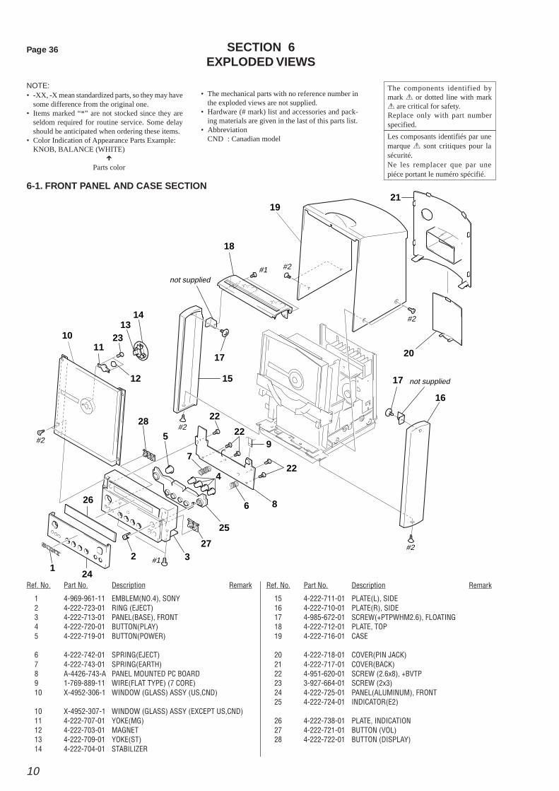
SECTION 6EXPLODED VIEWS
6-1. FRONT PANEL AND CASE SECTION
NOTE:• -XX, -X mean standardized parts, so they may have
some difference from the original one.• Items marked “*” are not stocked since they are
seldom required for routine service. Some delayshould be anticipated when ordering these items.
• Color Indication of Appearance Parts Example:KNOB, BALANCE (WHITE)
XParts color
• The mechanical parts with no reference number inthe exploded views are not supplied.
• Hardware (# mark) list and accessories and pack-ing materials are given in the last of this parts list.
• AbbreviationCND : Canadian model
Ref. No. Part No. Description Remark Ref. No. Part No. Description Remark
The components identified bymark 0 or dotted line with mark0 are critical for safety.Replace only with part numberspecified.
Les composants identifiés par unemarque 0 sont critiques pour lasécurité.Ne les remplacer que par unepiéce portant le numéro spécifié.
21
20
17
16
3
4
6
7
5
28
2
24
26
25
27
1#1
#2
#2
#2
#2
#2#1not supplied
not supplied
8
22
22
22
9
15
1711
10
12
1413
23
18
19
1 4-969-961-11 EMBLEM(NO.4), SONY2 4-222-723-01 RING (EJECT)3 4-222-713-01 PANEL(BASE), FRONT4 4-222-720-01 BUTTON(PLAY)5 4-222-719-01 BUTTON(POWER)
6 4-222-742-01 SPRING(EJECT)7 4-222-743-01 SPRING(EARTH)8 A-4426-743-A PANEL MOUNTED PC BOARD9 1-769-889-11 WIRE(FLAT TYPE) (7 CORE)10 X-4952-306-1 WINDOW (GLASS) ASSY (US,CND)
10 X-4952-307-1 WINDOW (GLASS) ASSY (EXCEPT US,CND)11 4-222-707-01 YOKE(MG)12 4-222-703-01 MAGNET13 4-222-709-01 YOKE(ST)14 4-222-704-01 STABILIZER
15 4-222-711-01 PLATE(L), SIDE16 4-222-710-01 PLATE(R), SIDE17 4-985-672-01 SCREW(+PTPWHM2.6), FLOATING18 4-222-712-01 PLATE, TOP19 4-222-716-01 CASE
20 4-222-718-01 COVER(PIN JACK)21 4-222-717-01 COVER(BACK)22 4-951-620-01 SCREW (2.6x8), +BVTP23 3-927-664-01 SCREW (2x3)24 4-222-725-01 PANEL(ALUMINUM), FRONT25 4-222-724-01 INDICATOR(E2)
26 4-222-738-01 PLATE, INDICATION27 4-222-721-01 BUTTON (VOL)28 4-222-722-01 BUTTON (DISPLAY)
Page 36

11
Page 37
6-2. CHASSIS SECTION
Ref. No. Part No. Description Remark Ref. No. Part No. Description Remark
#3
#1#1
#1#1
#1
#1
#1
#1#3
#1#1
#1
#1
#3
#3
#1
#3#1
#1#1#1
#3
not supplied
not supplied
not supplied
not supplied
not supplied
LCD701
not supplied not supplied
not supplied
not supplied
not supplied
54
55
57
58
646772
6162
5666
66
69
70
71
63 66 59
53
68
51
51
52
(US/CND)
(E)
(AEP/UK)
(HK)
(AUS)
(UK)
60
60
60
60
60
65
Les composants identifiés par unemarque 0 sont critiques pour lasécurité.Ne les remplacer que par unepiéce portant le numéro spécifié.
The components identified bymark 0 or dotted line with mark0 are critical for safety.Replace only with part numberspecified.
51 4-220-455-01 FOOT(FELT)52 4-222-715-01 PLATE, BOTTOM53 A-4426-745-A AMP MOUNTED PC BOARD (US,CND)53 A-4426-754-A AMP MOUNTED PC BOARD (EXCEPT US,CND)54 A-4426-744-A POWER MOUNTED PC BOARD (US,CND)
54 A-4426-753-A POWER MOUNTED PC BOARD (EXCEPT US,CND)* 55 1-675-407-11 REG BOARD
56 4-985-672-01 SCREW(+PTPWHM2.6), FLOATING57 3-703-244-00 BUSHING (2104), CORD (EXCEPT E)57 3-703-571-12 BUSHING S. (E)
58 4-222-730-01 PANEL, BACK59 A-4426-742-A MAIN MOUNTED PC BOARD (US,CND)59 A-4426-752-A MAIN MOUNTED PC BOARD (EXCEPT US,CND)
060 1-575-651-21 CORD,POWER (AEP,UK)060 1-783-531-31 CORD,POWER (US,CND)
61 1-674-910-11 LED BOARD62 1-791-698-11 WIRE (FLAT TYPE) (16 CORE)63 1-769-973-11 WIRE (FLAT TYPE) (13 CORE)64 1-693-407-13 TUNER (US,CND)64 1-693-408-12 TUNER (EXCEPT US,CND)
065 1-770-019-11 ADAPTOR, CONVERSION PLUG 3P (UK)66 3-314-903-01 CUSHION67 4-222-714-01 HOUSE, LAMP68 3-561-427-11 CUSHION(10x10x10)69 4-028-047-01 HEAT SINK, CLIP TYPE
70 4-224-740-01 INSLATED PLATE(POWER.1)71 4-224-741-01 INSLATED PLATE(POWER.2)72 4-222-740-01 ILLUMINATORLCD701 1-803-778-11 PANEL, LIQUID CRYSTAL

12
Sony CorporationHome Audio Division Company
9-929-017-81 1999L0985-1Printed in Japan © 1999. 12
Published by Quality Assurance Dept.
HCD-EX1
6-3. MECHANISM SECTION
Ref. No. Part No. Description Remark Ref. No. Part No. Description Remark
101 4-222-746-01 PLATE (CD) (LOWER), ORNAMENTAL102 4-222-745-01 PLATE (CD) (UPPER), ORNAMENTAL103 4-222-701-01 PANEL, MECHANICAL104 4-985-672-31 SCREW (+PTPWHM2.6), FLOATING105 4-222-697-01 RUBBER, FLOATING
106 4-222-692-01 HOLDER, BU107 4-222-702-01 SPRING, TENSION108 4-222-685-01 SLIDER (1)109 4-222-694-01 GEAR(1)110 4-999-513-01 GEAR, PULLEY
111 4-999-537-01 BELT(LOADING)112 4-222-695-01 GUIDE (R)113 4-222-693-01 SLIDER (4)114 4-222-700-01 GUIDE (L)115 4-222-687-01 BASE, MECHANICAL
116 4-222-688-01 HOLDER, DISC117 4-222-813-01 SLIDER (2)
118 4-225-227-01 SPRING (ABSORBER),TENSION COIL119 4-225-228-01 CAM(A)120 4-225-226-01 ABSORBER
121 4-222-689-01 SLIDER (3)122 4-222-690-01 COVER, MECHANICAL123 4-222-691-01 LEVER (1)124 4-951-620-01 SCREW (2.6X8), +BVTP
* 125 1-674-908-11 LOADING BOARD
* 126 1-674-909-11 SW BOARD127 1-791-698-11 WIRE (FLAT TYPE) (16 CORE)128 3-831-441-99 CUSHION129 X-4952-497-1 BASE ASSY, MOTOR130 A-4909-346-A BASE UNIT(KSM-770ACA)
131 3-946-435-11 SCREW(M2.6)132 4-225-234-01 GUIDE, DISC133 4-227-514-01 SPEAKERM351 X-4952-498-1 MOTOR ASSY
#6
M351
101
102
103
104
104 124
124
128
132
127
104
104
104
133
104
104
105
105
105
105106
107
107
108
114
113
116
117
115131
131
119120
122123
123
124
124
121
118
126
112
129
130
125
113111110
109124
124
124
Page 38