Foot Step Power Generation
Final year B.Tech in Mechanical Engineering[1],[2],[3],[4], Assistant Professor[5]
Department of Mechanical Engineering, Asansol Engineering College, Asansol - 713305
West Bengal, India.
---------------------------------------------------------------------***---------------------------------------------------------------------Abstract -Man has needed and used energy at an increasing rate for the sustenance and wellbeing since time immemorial. Due to this a lot of energy resources have been exhausted and wasted. Proposal for the utilization of waste energy of foot power with human locomotion is very much relevant and important for highly populated countries like India where the railway station, temples etc., are overcrowded all round the clock. In this paper the force energy is produced by human footsteps and the force energy is converted into mechanical energy by rack and pinion mechanism, electricity is produced by dc generator. And this power source has many applications as in agriculture, home application and street lighting and as energy source for sensors in remote locations. This paper is all about generating electricity when people walk on the Floor. Think about the forces you exert which is wasted when a person walks by. The idea is to convert the weight energy to electrical energy The Power generating floor intends to translate the kinetic energy to the electrical power. Energy Crisis is the main issue of world these days. The motto of this research work is to face this crisis somehow. Though it won’t meet the requirement of electricity but as a matter of fact if we are able to design a power generating floor that can produce 100W on just 12 steps, then for 120 steps we can produce 1000 Watt and if we install such type of 100 floors with this system then it can produce 1MegaWatt. Which itself is an achievement to make it significant.
Key Words:Renewable Energy, Foot step, Electricity, Generator.
1. INTRODUCTION For an alternate method to generate electricity there are number of methods by which electricity can be produced, out if such methods footstep energy generation can be an effective method to generate electricity. Walking is the most common activity in human life. When a person walks, he loses energy to the road surface in the form of impact, vibration, soundetc. Due to the transfer of his weight on to the road surface, through foot falls on the ground during every step. This energy can be tapped and converted in the usable form such as in electrical form. This device, if embedded in the footpath, can convert foot impact energy into electrical form. Human-powered transport has been in existence since time immemorial in the form of walking, running and swimming. However modern technology has led to machines to enhance the use of human-power in more
efficient manner. In this context, pedal power is an excellent source of energy and has been in use since the nineteenth century making use of the most powerful muscles in the body. Ninety-five percent of the exertion put into pedal power is converted into energy. However, human kinetic energy can be useful in a number of ways but it can also be used to generate electricity based on different approaches and many organizations are already implementing human powered technologies to generate electricity to power small electronic appliances.
1.1 Objective
To generate the electricity through the human
foot
To provide electricity in rural area
To promote the non-conventional energy source
To save conventional energy sources
To store the electricity for further use
To produce electricity at cheapest cost
To produce electricity while rack moves in
upward direction.
1.2 Working Principle
The basic working principle of our project is
based on the spring force that is used to convert
mechanicalinto the electrical energy.
This electrical energy will be stored in the 12V
rechargeable battery connected to inverter.
This inverter is used to convert the 12 Volt D.C to
the 230 Volt A.C. This 230 Volt A.C voltage is used
to activate the loads
Fig.1: Final Model
International Research Journal of Engineering and Technology (IRJET) e-ISSN: 2395-0056
Volume: 06 Issue: 05 | May 2019 www.irjet.net p-ISSN: 2395-0072
Rajeev Ranjan Tiwari[1], Rahul Bansal[2], Quamruzzaman[3],
Pushyamitra Gupta[4], Dr. Sarnendu Paul[5]
© 2019, IRJET | Impact Factor value: 7.211 | ISO 9001:2008 Certified Journal | Page 5094

1.3 Working Model of the system
The working of the Foot Step Electric Converter (FSEC) is
demonstrated:
I. When force is applied on the plate by standing on
plate the spring gets compressed.
II. The rack here moves vertically down.
III. The pinion meshed with the rack gear results in
circular motion of the pinion gear.
IV. For one full compression the pinion moves 1 full
circle.
V. When the force is released from the plate pinion
reverses and moves another circle and cause
rotation of gear pairs.
VI. The generator attached to the last gear hence
results in the dc power generation.
The power generated by the foot step generator can be
stored in an energy storing device. The output of the
generator was fed to a 12 V lead acid battery, through an
ac-dc converter bridge. Initially, the battery was
completely discharged. Then, the FSEC was operated by
applying foot load and energy was stored in the battery. A
100 W, 230V bulb was connected to the battery through
an inverter. The arrangement is shown in figure.4.
Fig.2: Block Diagram
Fig.3: Line Diagram of Foot Step Power Generation
This is the line diagram of foot step power generator. It
describes different components of the system in proper
manner. In which rack moves downward as human weight
applied which cause rotation of pinion on first shaft. A big
gear is mounted with pinion on shaft one which is
attached to the small gear of shaft two. Another big gear is
mounted with small gear on shaft two which is in contact
with gear of dc generator.
1.4 Need for the system
Fig.4: Need for the system
Proposal for the utilization of waste energy of foot power with human locomotion is very much relevant and important for highly populated countries like India and China where the roads, railway stations, bus stands, temples, etc. are all over crowded and millions of people move around the clock. This whole human/bioenergy being wasted if can be made possible for utilization it will be great invention and crowd energy farms will be very useful energy sources in crowded countries. Walking across a "Crowd Farm," floor, then, will be a fun for idle people who can improve their health by exercising in such farms with earning. The electrical energy generated at such farms will be useful for nearby applications.
The utilization of waste energy of foot power with human motion is very important for highly populated countries.
International Research Journal of Engineering and Technology (IRJET) e-ISSN: 2395-0056
Volume: 06 Issue: 05 | May 2019 www.irjet.net p-ISSN: 2395-0072
© 2019, IRJET | Impact Factor value: 7.211 | ISO 9001:2008 Certified Journal | Page 5095

India and China where the roads, railway stations, temples, etc. are all over crowded and millions of people move around the clock.
Vipin Kumar Yadav1, Vivek Kumar Yadav1, Rajat
Kumar1, Ajay Yadav, [2]In this research paper authors
used the equipment with following specification: Motor
Voltage:10 volt Type: D.C. Generator, RPM:1000 rpm, Gear
1-Mild Steel, No. of teeth:59(big gear),No. of
teeth:36(small gear),Type: Spur Gear, No. of gear used:2
Spring 1-Load bearing capacity:60-90 kg, Mild Steel, Total
displacement:5 inch, Bearing 1- Type: Ball bearing,
Bearing no.N35,Shaft 1- Diameter: 15 mm- Material: Mild
steel author concluded that with these method energy
conversion is simple efficient and pollution free.
From the viewpoint of Shiraz Afzal, and
FarrukhHafeez,[3]this paper is all about generating
electricity when people walk on the Floor if we are able to
design a power generating floor that can produce 100W
on just 12 steps, then for 120 steps we can produce 1000
Watt and if we install such type of 100 floors with this
system then it can produce 1MegaWattAs a fact only 11%
of renewable energy contributes to our primary energy. If
this project is deployed, then not only we can overcome
the energy crises problem but this also contributes to
create a healthy global environmental change. In this
project a gear system is attached with flywheel which
causes to rotate the dynamo as the tile on the deck is
pressed The power that is created is saved in the batteries
in addition we will be able to monitor and control the
amount of electricity generated When an individual passes
it push the tile on the ground surface which turn the shaft
beneath the tile, turn is limited by clutch bearing which is
underpinned by holders. Primary shaft is rotate approx.
twice by a single tile push ..The movement of the
prevailing shaft turn thegearbox shaft which builds it 15
times (1:15) then its movement is smoothen by the help of
fly wheel which temporary store the movement, which is
convey to the DC generator (it generates 12V 40 amp at
1000 rpm).
From the perspective of Sasankshekhar Panda has
described the based on crank shaft; fly wheel, and gear
arrangement. This type of footsteps power generation
system is eligible to be installed in crowded places and
rural areas. Thus, this is a very good technology to provide
effective solution to power related problems to affordable
extent. This will be the most acceptable means of
providing power to the places that involves difficulties of
transmission. Maintenance and lubrication is required
time to time. [4]
Jose AnanthVino described the simple drive mechanism
which include rack and pinion assembly and chain drive
mechanism. The conversion of the pressure or force
energy in to electrical energy. The power generation is
very high but the initial cost of this system is high. There is
no need of power from the mains and this system is eco-
friendly. It is very useful at the crowded places and on all
roads and as well as all kind of foot step which is used to
generate the electricity. Maintenance and lubrication is
required time to time. Power is not generated during
return movement of rack. [5]
3. COMPONENTS OF THE SYSTEM
Rack and pinion: A rack and pinion gears system is
composed of two gears. The normal round gear is the
pinion gear and the straight or flat gear is the rack. A rack
and pinion are types of linear actuator that comprises a
pair of gears which convert rotational motion into linear
motion. The circular pinion engages teeth on a linear
"gear" bar which is called the “rack“.
Fig.5: Rack and Pinion
Gears: A gear is a rotating machine part having cut teeth
which mesh with another toothed part to transmit torque.
Geared devices can change the speed, torque, and
direction of a power source. Gears almost always produce
a change in torque, creating a mechanical advantage,
through their gear ratio, and thus may be considered a
simple machine.
2. LITERATURE REVIEW According to T.R.Deshmukh described along with design
International Research Journal of Engineering and Technology (IRJET) e-ISSN: 2395-0056
Volume: 06 Issue: 05 | May 2019 www.irjet.net p-ISSN: 2395-0072
and modeling of parts of the model of the foot step power
generation system using 3d modeling software. This
process consists number of simple setups that is installed
under the walking or standing platform. Project system
works on the principle of converting the linear motion
because to pressure of footsteps into rotating motion by
rack and pinion arrangement. This mechanism fails if
there is any occurrence of variable load leads to balancing
type problems Power is not generated during return
movement of rack. [1]
© 2019, IRJET | Impact Factor value: 7.211 | ISO 9001:2008 Certified Journal | Page 5096
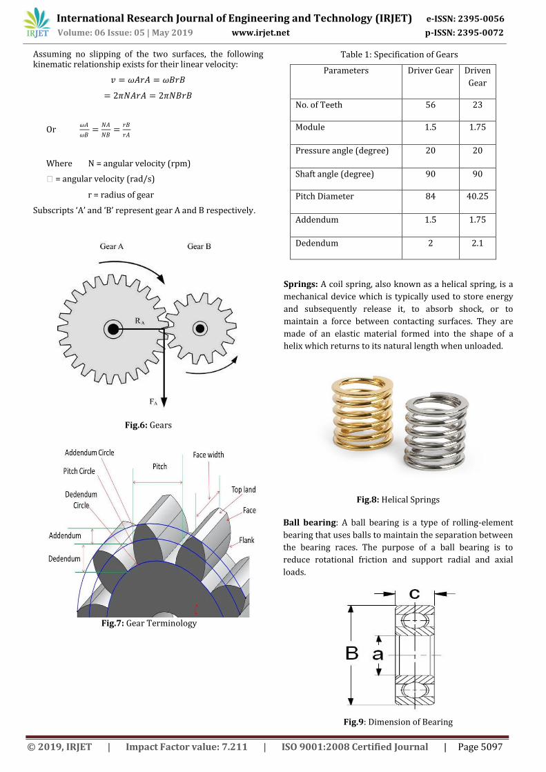
Assuming no slipping of the two surfaces, the following kinematic relationship exists for their linear velocity:
𝑣 = 𝜔𝐴𝑟𝐴 = 𝜔𝐵𝑟𝐵
= 2𝜋𝑁𝐴𝑟𝐴 = 2𝜋𝑁𝐵𝑟𝐵
Or 𝜔𝐴
𝜔𝐵=
𝑁𝐴
𝑁𝐵=
𝑟𝐵
𝑟𝐴
Where N = angular velocity (rpm)
ꞷ = angular velocity (rad/s)
r = radius of gear
Subscripts ‘A’ and ‘B’ represent gear A and B respectively.
Fig.6: Gears
Fig.7: Gear Terminology
Table 1: Specification of Gears
Parameters Driver Gear Driven
Gear
No. of Teeth 56 23
Module 1.5 1.75
Pressure angle (degree) 20 20
Shaft angle (degree) 90 90
Pitch Diameter 84 40.25
Addendum 1.5 1.75
Dedendum 2 2.1
Springs: A coil spring, also known as a helical spring, is a
mechanical device which is typically used to store energy
and subsequently release it, to absorb shock, or to
maintain a force between contacting surfaces. They are
made of an elastic material formed into the shape of a
helix which returns to its natural length when unloaded.
Fig.8: Helical Springs
Ball bearing: A ball bearing is a type of rolling-element
bearing that uses balls to maintain the separation between
the bearing races. The purpose of a ball bearing is to
reduce rotational friction and support radial and axial
loads.
Fig.9: Dimension of Bearing
International Research Journal of Engineering and Technology (IRJET) e-ISSN: 2395-0056
Volume: 06 Issue: 05 | May 2019 www.irjet.net p-ISSN: 2395-0072
© 2019, IRJET | Impact Factor value: 7.211 | ISO 9001:2008 Certified Journal | Page 5097
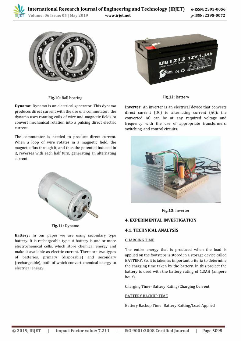
Fig.10: Ball bearing
Dynamo: Dynamo is an electrical generator. This dynamo
produces direct current with the use of a commutator. the
dynamo uses rotating coils of wire and magnetic fields to
convert mechanical rotation into a pulsing direct electric
current.
The commutator is needed to produce direct current.
When a loop of wire rotates in a magnetic field, the
magnetic flux through it, and thus the potential induced in
it, reverses with each half turn, generating an alternating
current.
Fig.11: Dynamo
Battery: In our paper we are using secondary type
battery. It is rechargeable type. A battery is one or more
electrochemical cells, which store chemical energy and
make it available as electric current. There are two types
of batteries, primary (disposable) and secondary
(rechargeable), both of which convert chemical energy to
electrical energy.
Fig.12: Battery
Inverter: An inverter is an electrical device that converts
direct current (DC) to alternating current (AC); the
converted AC can be at any required voltage and
frequency with the use of appropriate transformers,
switching, and control circuits.
Fig.13: Inverter
4. EXPERIMENTAL INVESTIGATION
4.1. TECHNICAL ANALYSIS
CHARGING TIME
The entire energy that is produced when the load is
applied on the footsteps is stored in a storage device called
BATTERY. So, it is taken as important criteria to determine
the charging time taken by the battery. In this project the
battery is used with the battery rating of 1.3AH (ampere
hour).
Charging Time=Battery Rating/Charging Current
BATTERY BACKUP TIME
Battery Backup Time=Battery Ratting/Load Applied
International Research Journal of Engineering and Technology (IRJET) e-ISSN: 2395-0056
Volume: 06 Issue: 05 | May 2019 www.irjet.net p-ISSN: 2395-0072
© 2019, IRJET | Impact Factor value: 7.211 | ISO 9001:2008 Certified Journal | Page 5098

THEORITICAL POWER OUTPUT
To determine the output power, it is essential to
determine the force applied on the model. Let the force
applied be calculated as,
Force=Weight of the Body= m .g
Work done =Force x Displacement
Power= Work done/Sec
Let the weight applied by the body is 20kgs, then the
maximum displacement of the spring can be noted as
0.05m
Force =20 x 9.81=196.2N
Work done =196.2 x 0.05
i.e., work done = 9.81
Power=0.981\60
i.e., power =0.1635
Power generated per an hour = 0.1635 x 3600 =
588.6Watts
PRACTICAL POWER OUTPUT
Power can be calculated in terms of obtained voltage and
current when the load is applied on the footsteps. The
readings are noted by using the Multimeter.
Power = Voltage x Current
Here, when the foot is depressed due to the applied load
on the footsteps the calculated power is as follows.
For one step of 20kg of load applied on the footsteps, the
generated voltage is 2.6V and the average current
produced is 12milliamps.
Power = 2.6 x 0.012 = 0.0312
Power generated per hour is0.0312 x 3600 = 112.3Watts.
Thus, the obtained power for continuous load applied on
the footsteps for one hour is 112.3Watts.
4.2. Advantages
Power generation is simply walking on step.
No need of fuel input.
This is a non-conventional system.
Self-generation - no external power required.
Compact yet highly sensitive.
Battery is used to store the generated power.
Reliable, Economical, Eco-Friendly.
Extremely wide dynamic range, almost free of
noise.
4.3. Disadvantages
Only applicable for the particular places.
Initial cost of this arrangement is high.
Output affected by temperature variation.
Care should be taken for batteries.
4.4. Applications
Foot step generated power can be used for
agricultural, home applications, street
lighting.
Foot step power generation can be used in
emergency power failure situations.
Metros, Rural Applications etc.
It can be used as a source for D.C applications
It is also used in universities
It can use in emergency power failure
situations like hospitals.
5. CONCLUSION The project “POWER GENERATION USING FOOT STEP” is
successfully tested and implemented which is the best
economical, affordable energy solution to common people.
This can be used for many applications in rural areas
where power availability is less or totally absence. Since
India is an developing country where energy management
is a big challenge for huge population. By using this
project, we can drive D.C loads
It is especially suited for implementation in crowded
areas. This can be used in street lighting without use of
long power lines. It can also be used as charging ports,
lighting of pavement side buildings.
As a fact only 11% of renewable energy contributes to our
primary energy. If this project is deployed then not only,
we can overcome the energy crises problem but this also
contributes to create a healthy global environmental
change.
Smart system.
Produces 2000W of electricity
Durable.
Have a life of approx. 5 yrs.
International Research Journal of Engineering and Technology (IRJET) e-ISSN: 2395-0056
Volume: 06 Issue: 05 | May 2019 www.irjet.net p-ISSN: 2395-0072
© 2019, IRJET | Impact Factor value: 7.211 | ISO 9001:2008 Certified Journal | Page 5099

ACKNOWLEDGEMENT
We would like to express our heartiest gratitude and
thanks to all who gave us this great opportunity to
complete our project. We would like to thank everyone
who helped us and made thus experience such memorable
one.
We would like to express our gratitude to Prof. (Dr.) P.K
Bandyopadhyay (H.O.D, Mechanical Engineering
Department, Asansol Engineering College) for permitting
us to undergo this work.
To our Guide Dr. Sarnendu Paul (Asst. Professor) for being
so helpful and taking keen interest in our progress and
always helped us when we faced any kind of technical
problems.
To Mr. Sanjay Thakur and Mr. Faiz Ansari for helping in
workshop in completion of project.
Further our thanks goes to all respected faculty members
and staffs of the department of Mechanical Engineering,
Asansol Engineering College as they remained keenly
attached to us in every aspect for the completion of our
project.
We express our sincere thanks to all our friends and our
families, who directly or indirectly, helped us in the
accomplishment of this work.
REFERENCES
[1] T.R.Deshmukh. Design and analysis of a Mechanical
Device to harvest energy from human footstep
motion Volume 3, Special Issue 1,ICSTSD 2016M.
Young, The Technical Writer’s Handbook. Mill Valley,
CA: University Science, 1989.
[2] “Power generation through step” by Vipin Kumar
Yadav, Vivek Kumar Yadav, Rajat Kumar, Ajay Yadav
[3] “Power Generation Footstep” by Shiraz Afzal,
Farrukhhafeez
[4] Sasankshekhar Panda. An Investigation on Generation
of Electricity Using Foot Step ISSN: 2277-9655
Scientific Journal Impact Factor: 3.449 (ISRA), Impact
Factor: 1.852 K. Elissa, “Title of paper if known,”
unpublished.
[5] Jose Ananth Vino. Power Generation Using Foot Step,
International Journal of Engineering Trends and
Technology (IJETT) Volume1 Issue2 May 2011.
International Research Journal of Engineering and Technology (IRJET) e-ISSN: 2395-0056
Volume: 06 Issue: 05 | May 2019 www.irjet.net p-ISSN: 2395-0072
© 2019, IRJET | Impact Factor value: 7.211 | ISO 9001:2008 Certified Journal | Page 5100


![POWER GENERATING USING HUMAN FOOT STEP WITH PIZEO … · POWER GENERATING USING HUMAN FOOT STEP WITH PIZEO ELECTRIC SENSOR AND TREADMILL Gopinath.R [1] [2], M.Lavanya ,M.Arivalagan](https://static.cupdf.com/doc/110x72/5fe854861e034c0040192110/power-generating-using-human-foot-step-with-pizeo-power-generating-using-human-foot.jpg)