
1www.erico.pentair.com 1.800.831.7133
GROUNDING, BONDING AND ERICO CADWELD
ERICO · 1.800.677.9089 · www.erico.pentair.com
SOLUTIONS GUIDE

2 www.erico.pentair.com
IntroductionPentair Engineered Electrical & Fastening Solutions is a leading global manufacturer and marketer of superior engineered products for niche electrical, mechanical and concrete applications. These Pentair products are sold globally under a variety of market-leading brands: ERICO welded electrical connections, facility electrical protection, and rail and industrial products; CADDY fixing, fastening and support products; ERIFLEX low voltage power and grounding connections; and LENTON engineered systems for concrete reinforcement.
For more information on ERICO, CADDY, ERIFLEX and LENTON, please visit erico.pentair.com.
WARNINGPentair products shall be installed and used only as indicated in Pentair’s product instruction sheets and training materials. Instruction sheets are available at www.erico.pentair.com and from your Pentair customer service representative. Improper installation, misuse, misapplication or other failure to completely follow Pentair’s instructions and warnings may cause product malfunction, property damage, serious bodily injury and death and/or void your warranty.
© 2009 – 2010, 2016 Pentair All Rights ReservedPentair, CADDY, CADWELD, CRITEC, ERICO, ERIFLEX and LENTON are owned by Pentair or its global affiliates. All other trademarks are the property of their respective owners. Pentair reserves the right to change specifications without prior notice.
3www.erico.pentair.com 1.800.677.9089
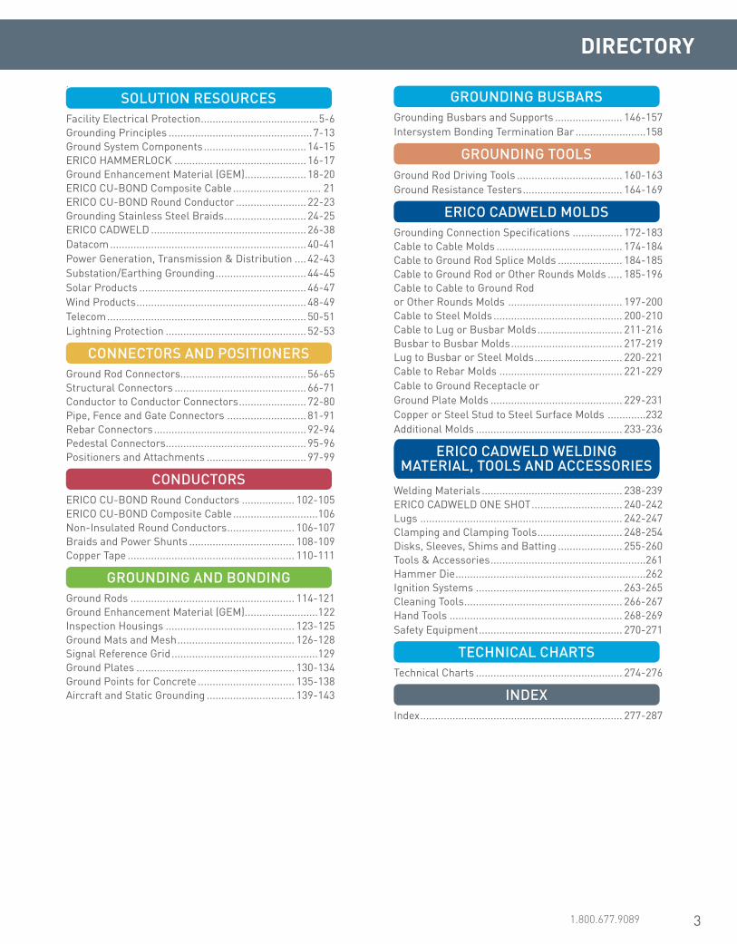
DIRECTORY
i SOLUTION RESOURCESFacility Electrical Protection ........................................5-6Grounding Principles .................................................7-13Ground System Components ................................... 14-15ERICO HAMMERLOCK ............................................. 16-17Ground Enhancement Material (GEM) ..................... 18-20ERICO CU-BOND Composite Cable .............................. 21ERICO CU-BOND Round Conductor ........................ 22-23Grounding Stainless Steel Braids ............................ 24-25ERICO CADWELD ..................................................... 26-38Datacom ................................................................... 40-41Power Generation, Transmission & Distribution .... 42-43 Substation/Earthing Grounding ............................... 44-45Solar Products ......................................................... 46-47Wind Products .......................................................... 48-49Telecom .................................................................... 50-51Lightning Protection ................................................ 52-53
CONNECTORS AND POSITIONERSGround Rod Connectors........................................... 56-65Structural Connectors ............................................. 66-71Conductor to Conductor Connectors ....................... 72-80Pipe, Fence and Gate Connectors ........................... 81-91Rebar Connectors .................................................... 92-94Pedestal Connectors ................................................ 95-96Positioners and Attachments .................................. 97-99
CONDUCTORSERICO CU-BOND Round Conductors .................. 102-105ERICO CU-BOND Composite Cable .............................106Non-Insulated Round Conductors ....................... 106-107Braids and Power Shunts .................................... 108-109Copper Tape ......................................................... 110-111
GROUNDING AND BONDINGGround Rods ........................................................ 114-121Ground Enhancement Material (GEM) .........................122Inspection Housings ............................................ 123-125Ground Mats and Mesh ........................................ 126-128Signal Reference Grid ..................................................129Ground Plates ...................................................... 130-134Ground Points for Concrete ................................. 135-138Aircraft and Static Grounding .............................. 139-143
GROUNDING BUSBARSGrounding Busbars and Supports ....................... 146-157Intersystem Bonding Termination Bar ........................158
GROUNDING TOOLSGround Rod Driving Tools .................................... 160-163Ground Resistance Testers .................................. 164-169
ERICO CADWELD MOLDSGrounding Connection Specifications ................. 172-183Cable to Cable Molds ........................................... 174-184Cable to Ground Rod Splice Molds ...................... 184-185Cable to Ground Rod or Other Rounds Molds ..... 185-196Cable to Cable to Ground Rod or Other Rounds Molds ....................................... 197-200Cable to Steel Molds ............................................ 200-210Cable to Lug or Busbar Molds ............................. 211-216Busbar to Busbar Molds ...................................... 217-219Lug to Busbar or Steel Molds .............................. 220-221Cable to Rebar Molds .......................................... 221-229Cable to Ground Receptacle or Ground Plate Molds ............................................. 229-231 Copper or Steel Stud to Steel Surface Molds .............232Additional Molds .................................................. 233-236
ERICO CADWELD WELDING MATERIAL, TOOLS AND ACCESSORIES
Welding Materials ................................................ 238-239ERICO CADWELD ONE SHOT ............................... 240-242Lugs ..................................................................... 242-247Clamping and Clamping Tools ............................. 248-254Disks, Sleeves, Shims and Batting ...................... 255-260Tools & Accessories .....................................................261Hammer Die .................................................................262Ignition Systems .................................................. 263-265Cleaning Tools ...................................................... 266-267Hand Tools ........................................................... 268-269Safety Equipment ................................................. 270-271
TECHNICAL CHARTSTechnical Charts .................................................. 274-276
INDEXIndex ..................................................................... 277-287

4 www.erico.pentair.com

5www.erico.pentair.com
1
2
5
43
Power Protection TVSS Device
Communications Line Protection Device
Ground Electrode
Power Distribution Panel
Telephone Main Distribution Frame
PCS, Radio & Telemetry Equipment
Power Ground
AC Transformer Sub Station
Overhead Distribution Voltage Transmission Lines
Telephone Lines
Direct Lightning Strike
ERICO SYSTEM 3000 Active Lightning Protection System
Capture the lightning strike
Dissipate Energy into the Grounding System
Low Impedance Ground using flat copper radials and
Ground Enhancement Material
Inspection Well
Safely Convey Energy to Ground
Protect Incoming AC Power Feeders
IS File
Server
PABX
InverterRectifier
Batteries
Ground Potential Equalization Bonding
TVSS
Remote Data Terminal
Sub-Distribution Board
Bond All Ground Points Together
PrinterBilling Computer
Signal Control Lines
Induced Surge
Lightning strikes and the dangerous over-voltage surges caused by lightning and man-made events represent a direct threat to people, buildings and sensitive electronic equipment.
Today, the consequences of an unexpected lightning strike or power surge can be catastrophic for a company. Proper protection can save thousands of dollars in damage, operational downtime and lost business opportunities.
Total Facility ProtectionThe consequences of an unexpected lightning strike or power surge can be catastrophic for a facility:
• Personnel are at risk. • Critical equipment may be damaged or destroyed. • Data can be corrupted. • The costs of operational downtime and lost revenue can be very
substantial.
As industries become more dependent on increasingly sensi-tive equipment, proper protection from lightning and dangerous over-voltage transients is necessary.
With over 60 years of research, testing and product development, ERICO has acknowledged that no single technology can totally eliminate vulnerability to lightning and surges.
The ERICO Six Point Plan of Protection is designed to provide total facility protection by integrating several concepts.
The Six Point Plan will minimize the risk of damage to facilities through:
• Direct Strike Protection • Grounding and Bonding • Surge and Over-voltage Transient Protection
Because lightning protection, grounding, equipotential bonding and surge protection are all interdependent technologies, reliable protection of structures and operations demands an integrated system approach.
ERICO is a leading global designer, manufacturer and marketer of precision-engineered specialty metal products serving niche markets in a diverse range of electrical, construction, utility and rail applications. The company is headquartered in Solon, Ohio, USA with a network of sales locations serving more than 25 countries and with manufacturing and distribution facilities worldwide.
ERICO’s well-known brand names include: CADDY electrical and mechanical fixings, fasteners and supports; CADWELD welded electrical connections; ERICO surge protection devices; ERICO rail and industrial products; ERIFLEX low voltage power distribution; ERICO facility electrical protection; and LENTON concrete products. Visit ERICO online at www.ERICO.com.
ERICO SYSTEM 3000 Active Lightning Protection SystemERICO SYSTEM 2000
Conventional Lightning Protection System
The Six Point Plan of Protection from ERICOCapture the lightning strike.Capture the lightning strike to a known and preferred attachment point using a purpose-designed air terminal system.
Convey this energy to ground.Conduct the energy to the ground via a purpose-designed downconductor.
Dissipate energy into the grounding system.Dissipate energy into a low impedance grounding system.
Bond all ground points together.Bond all ground points to eliminate ground loops and create an equipotential plane.
Protect incoming AC power feeders.Protect equipment from surges and transients on incoming power lines to prevent equipment damage and costly operational downtime.
Protect low voltage data/telecommunications circuits.Protect equipment from surges and transients on incoming telecommunications and signal lines to prevent equipment damage and costly operational downtime.
1
2
3
4
5
6
6 Protect Low Voltage Data/Telecommunications Circuits
Facility Electrical Protection for the 21st Century
1.800.677.9089
6 www.erico.pentair.com
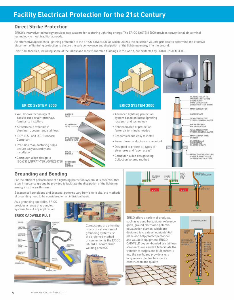
Facility Electrical Protection for the 21st Century
Direct Strike ProtectionERICO’s innovative technology provides two systems for capturing lightning energy. The ERICO SYSTEM 2000 provides conventional air terminal technology to meet traditional needs.
An alternative approach to lightning protection is the ERICO SYSTEM 3000, which utilizes the collection volume principle to determine the effective placement of lightning protection to ensure the safe conveyance and dissipation of the lightning energy into the ground.
Over 7000 facilities, including some of the tallest and most vulnerable buildings in the world, are protected by ERICO SYSTEM 3000.
• Well known technology of passive rods or air terminals, familiar to installers
• Air terminals available in aluminum, copper and stainless
• IEC®, B.S., and U.S. Standard Compliant
• Precision manufacturing helps ensure easy assembly and installation
• Computer-aided design to IEC62305,NFPA®-780, AS/NZS1768
• Advanced lightning protection system based on latest lightning research and technology
• Enhanced area of protection, fewer air terminals needed
• Economical and easy to install
• Fewer downconductors are required
• Designed to protect all types of structures and “open areas”
• Computer-aided design using Collection Volume method
Grounding and BondingFor the efficient performance of a lightning protection system, it is essential that a low impedance ground be provided to facilitate the dissipation of the lightning energy into the earth mass.
Because soil conditions and seasonal patterns vary from site to site, the methods of grounding need to be considered on an individual basis.
As a grounding specialist, ERICO provides a range of grounding systems to suit any application.
ERICO offers a variety of products, such as ground bars, signal reference grids, ground plates and potential equalization clamps, which are designed to create an equipotential plane and help protect personnel and valuable equipment. ERICO CADWELD copper-bonded or stainless steel earth rods and GEM facilitate the transfer of surges and fault currents into the earth, and provide a very long service life due to superior construction and quality.
Connections are often the most critical element of grounding systems, so the preferred method of connection is the ERICO CADWELD exothermic welding process.
EARTH PIT
LIGHTNINGDOWN-CONDUCTOR
TELECOM EARTH MAINS EARTH LP EARTH
TELECOMEARTHBAR
POWEREARTHBAR
MAINSPOWEREARTHWIRE
* *
ERITECHCOPPERBONDEDGROUNDROD
GEM GROUNDENHANCEMENTMATERIAL
ACCESSWELL
DOWNCONDUCTOR
ERICO SYSTEM 2000 ERICO SYSTEM 3000
P.E.C. P.E.C.
ERICO CADWELD PLUS
www.erico.pentair.com 1.800.677.9089
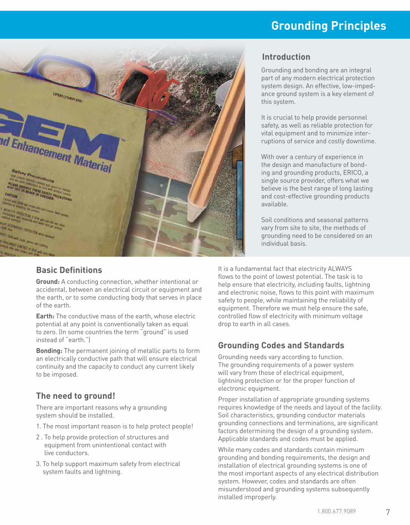
Grounding and bonding are an integral part of any modern electrical protection system design. An effective, low-imped-ance ground system is a key element of this system.
It is crucial to help provide personnel safety, as well as reliable protection for vital equipment and to minimize inter-ruptions of service and costly downtime.
With over a century of experience in the design and manufacture of bond-ing and grounding products, ERICO, a single source provider, offers what we believe is the best range of long lasting and cost-effective grounding products available.
Soil conditions and seasonal patterns vary from site to site, the methods of grounding need to be considered on an individual basis.
Introduction
Basic DefinitionsGround: A conducting connection, whether intentional or accidental, between an electrical circuit or equipment and the earth, or to some conducting body that serves in place of the earth.
Earth: The conductive mass of the earth, whose electric potential at any point is conventionally taken as equal to zero. (In some countries the term “ground” is used instead of “earth.”)
Bonding: The permanent joining of metallic parts to form an electrically conductive path that will ensure electrical continuity and the capacity to conduct any current likely to be imposed.
The need to ground!There are important reasons why a grounding system should be installed.
1. The most important reason is to help protect people!
2 . To help provide protection of structures and equipment from unintentional contact with live conductors.
3. To help support maximum safety from electrical system faults and lightning.
It is a fundamental fact that electricity ALWAYS flows to the point of lowest potential. The task is to help ensure that electricity, including faults, lightning and electronic noise, flows to this point with maximum safety to people, while maintaining the reliability of equipment. Therefore we must help ensure the safe, controlled flow of electricity with minimum voltage drop to earth in all cases.
Grounding Codes and StandardsGrounding needs vary according to function. The grounding requirements of a power system will vary from those of electrical equipment, lightning protection or for the proper function of electronic equipment.
Proper installation of appropriate grounding systems requires knowledge of the needs and layout of the facility. Soil characteristics, grounding conductor materials grounding connections and terminations, are significant factors determining the design of a grounding system. Applicable standards and codes must be applied.
While many codes and standards contain minimum grounding and bonding requirements, the design and installation of electrical grounding systems is one of the most important aspects of any electrical distribution system. However, codes and standards are often misunderstood and grounding systems subsequently installed improperly.
Grounding Principles
7
8 www.erico.pentair.com
Grounding Principles
Why is Good Grounding Important?The transient nature of lightning with its associated fast rise times and large magnitude currents mean that special consideration needs to be given to grounding, for lightning protection to be effective. Many factors such as soil resistivity variations, installation accessibility, layout and existing physical features are all site specific and tend to affect decisions on grounding methods employed. The primary aim of a direct strike grounding system is to:
• Efficiently dissipate lightning energy into the ground
• Help protect equipment and personnel
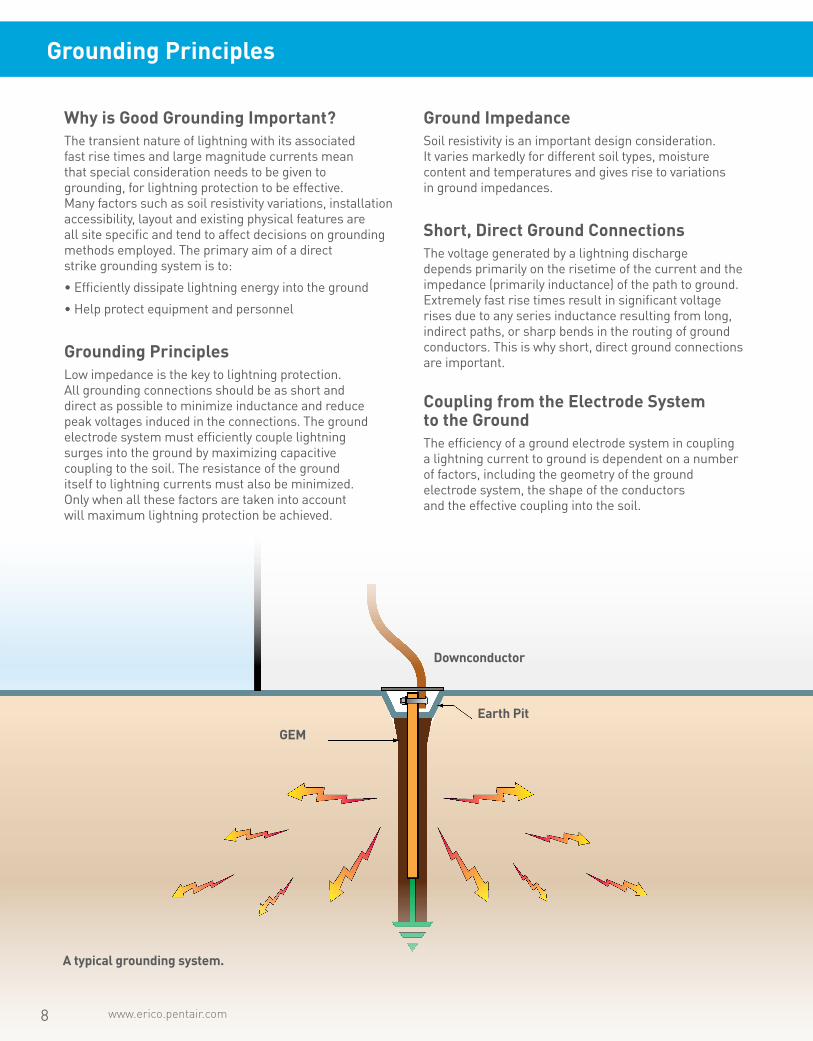
Grounding PrinciplesLow impedance is the key to lightning protection. All grounding connections should be as short and direct as possible to minimize inductance and reduce peak voltages induced in the connections. The ground electrode system must efficiently couple lightning surges into the ground by maximizing capacitive coupling to the soil. The resistance of the ground itself to lightning currents must also be minimized. Only when all these factors are taken into account will maximum lightning protection be achieved.
Ground ImpedanceSoil resistivity is an important design consideration. It varies markedly for different soil types, moisture content and temperatures and gives rise to variations in ground impedances.
Short, Direct Ground ConnectionsThe voltage generated by a lightning discharge depends primarily on the risetime of the current and the impedance (primarily inductance) of the path to ground. Extremely fast rise times result in significant voltage rises due to any series inductance resulting from long, indirect paths, or sharp bends in the routing of ground conductors. This is why short, direct ground connections are important.
Coupling from the Electrode System to the GroundThe efficiency of a ground electrode system in coupling a lightning current to ground is dependent on a number of factors, including the geometry of the ground electrode system, the shape of the conductors and the effective coupling into the soil.
A typical grounding system.
Downconductor
Earth Pit
GEM

www.erico.pentair.com 1.800.677.9089 9
Figure 1-A
Distance from the electrode
Figure 1-B
Ground Rod
Figure 1-B illustrates current flow from the injection point of a single ground electrode. As current flows out from the central injection point, a voltage gradient on the ground surface around the electrode is produced. This gradient levels off to a plateau at some distance from the electrode, as seen in Figure 1-A. The impedance seen by the current is determined by the soil particles in direct contact with the surface of the rod, and by the general impedance of the soil.
• Good electrical conductivity
• Conductors capable of withstanding available electri-cal fault currents
• Long life — at least 40 years
• Low ground resistance and impedance
The basic philosophy of any grounding installation should be an attempt to maximize the surface area of electrodes or conductors with the surrounding soil. Not only does this help to lower the earth resistance of the grounding system, but it also greatly improves the impedance of the grounding system under lightning surge conditions.
• Equipotential bonding
Equipotential bonding helps ensure that hazardous potential differences do not occur between different incoming conductors such as metallic water services, power systems, telecommunication systems and the local ground, and also minimizes step and touch potentials.
• Good corrosion resistance
The ground electrode system should be corrosion resistant, and compatible with other conductors that are buried and bonded to the ground system. Copper is by far the most common material used for grounding conductors. In gen-eral, some form of maintenance or inspection procedure should be adopted to ensure the long-term effectiveness of a grounding system.
• Electrically and mechanically robust and reliable
Mechanical coupling can be used to join ground conductors, but suffers from corrosion effects when dissimilar metals are involved. As well as mechanical strength, ERICO CADWELD connections provide excellent low impedance, long life electrical connections with excellent corrosion resistance.
When current flows from a ground electrode into the surrounding soil, it is often described as flowing through a series of concentric shells of increasing diameter.
Each successive shell has a greater area for current flow and consequently, lower resistance. At some point distant from the earth conductor the current dissipation becomes so large and current density so small, that the resistance is negligible.
In theory, the ground resistance may be derived from the general formula:
R = resistance in ohms of the ground rod to the earth (or soil)L = grounding electrode lengthr = grounding electrode radiusρ = average resistivity in ohms-cm.
In the case of ground resistance, uniform earth (or soil) resistivity throughout the volume is assumed, although this is seldom the case in nature. The equations for systems of electrodes are very complex and often expressed only as approximations. The most commonly used formula for single ground electrode systems, developed by Professor H.R. Dwight of the Massachusetts Institute of Technology, is the following:
This formula illustrates why the shells of concentric earth decrease in resistance the farther they are from the ground rod:
Ground Resistance
R = P L Resistance = Resistivity x Length
A
Area
R = Resistivity of Soil x Thickness of Shell
Area
R = __ {(ln 4L) - 1} 2πL r
ρ
Grounding Principles
10 www.erico.pentair.com
Grounding Principles
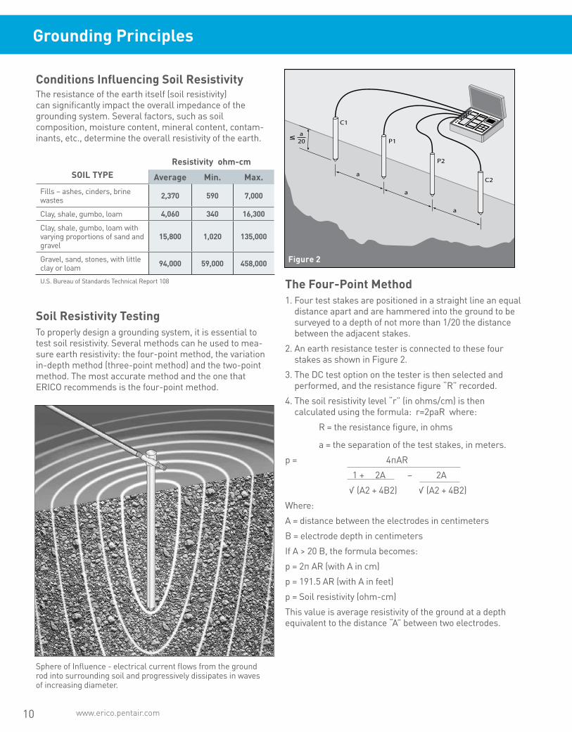
Conditions Influencing Soil ResistivityThe resistance of the earth itself (soil resistivity) can significantly impact the overall impedance of the grounding system. Several factors, such as soil composition, moisture content, mineral content, contam-inants, etc., determine the overall resistivity of the earth.
SOIL TYPEResistivity ohm-cm
Average Min. Max.Fills – ashes, cinders, brine wastes 2,370 590 7,000
Clay, shale, gumbo, loam 4,060 340 16,300
Clay, shale, gumbo, loam with varying proportions of sand and gravel
15,800 1,020 135,000
Gravel, sand, stones, with little clay or loam 94,000 59,000 458,000
U.S. Bureau of Standards Technical Report 108
Soil Resistivity TestingTo properly design a grounding system, it is essential to test soil resistivity. Several methods can he used to mea-sure earth resistivity: the four-point method, the variation in-depth method (three-point method) and the two-point method. The most accurate method and the one that ERICO recommends is the four-point method.
Sphere of Influence - electrical current flows from the ground rod into surrounding soil and progressively dissipates in waves of increasing diameter.
The Four-Point Method1. Four test stakes are positioned in a straight line an equal
distance apart and are hammered into the ground to be surveyed to a depth of not more than 1/20 the distance between the adjacent stakes.
2. An earth resistance tester is connected to these four stakes as shown in Figure 2.
3. The DC test option on the tester is then selected and performed, and the resistance figure “R” recorded.
4. The soil resistivity level “r” (in ohms/cm) is then calculated using the formula: r=2paR where:
R = the resistance figure, in ohms
a = the separation of the test stakes, in meters.
p = 4πAR
1 + 2A – 2A
√ (A2 + 4B2) √ (A2 + 4B2)
Where:
A = distance between the electrodes in centimeters
B = electrode depth in centimeters
If A > 20 B, the formula becomes:
p = 2π AR (with A in cm)
p = 191.5 AR (with A in feet)
p = Soil resistivity (ohm-cm)
This value is average resistivity of the ground at a depth equivalent to the distance “A” between two electrodes.
Figure 2
11www.erico.pentair.com 1.800.677.9089
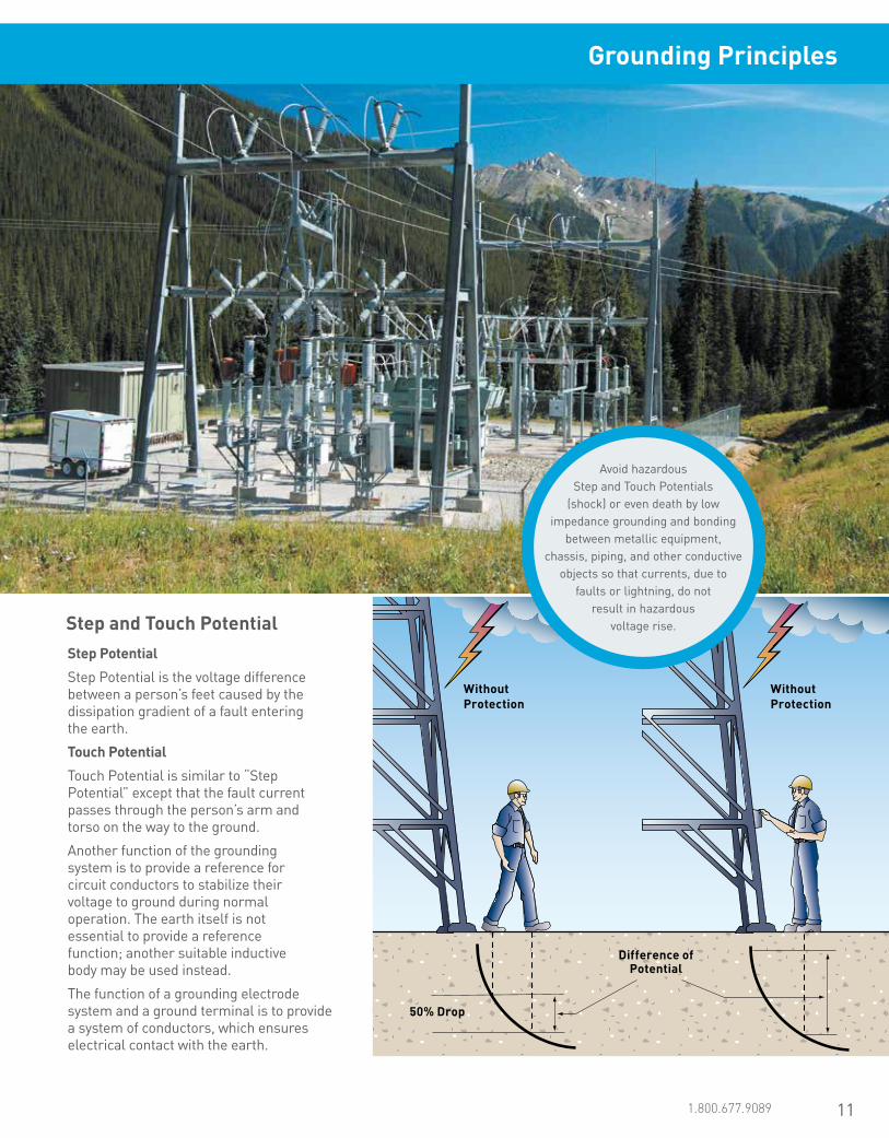
Step and Touch Potential
Without Protection
Without Protection
Difference of Potential
50% Drop
Step Potential
Step Potential is the voltage difference between a person’s feet caused by the dissipation gradient of a fault entering the earth.
Touch Potential
Touch Potential is similar to “Step Potential” except that the fault current passes through the person’s arm and torso on the way to the ground.
Another function of the grounding system is to provide a reference for circuit conductors to stabilize their voltage to ground during normal operation. The earth itself is not essential to provide a reference function; another suitable inductive body may be used instead.
The function of a grounding electrode system and a ground terminal is to provide a system of conductors, which ensures electrical contact with the earth.
Avoid hazardous Step and Touch Potentials
(shock) or even death by low impedance grounding and bonding
between metallic equipment, chassis, piping, and other conductive
objects so that currents, due to faults or lightning, do not
result in hazardous voltage rise.
Grounding Principles

12 www.erico.pentair.com
Grounding Principles
Grounding / Earthing System DesignGrounding systems are important. It is not expensive to build an appropriate ground system during initial con-struction of a facility, but it can be very expensive to add to it, enhance it, or replace it after the facility is complete. Care should be taken to design a system that is appro-priate both for clearing ground faults and dissipating lightning energy. The system must have a long perfor-mance life, meet applicable codes / standards for safety, and have sufficient bonding points to make it easy to add new equipment / facility grounding to it easily.
For proper operation of overcurrent devices, it is important to have a low DC ohmic resistance to remote earth. In many instances, this is best achieved by installing a deep ground electrode on site. It should be driven deep enough to reach the permanent water table.
For dissipation of direct or indirect lightning currents, it is better to have many horizontal ground conductors in the soil, preferably in a radial array. This provides a low impedance path of dissipation to the high frequency component of the lightning energy.
For personnel, particularly where people congregate or where equipment operators will be located, it is important to have a grid system or other equipotential plane to reduce “step potential” and have equipment and metal structures bonded to the ground system to reduce “touch potential”.
Design considerations include:
• Purpose of facility
• Design life of facility
• Soil resistivity at 3 depths
• Corrosive nature of soil
• Shape and available area of facility site
• Existing structures and their grounding systems
• Seasonal variations in moisture and temperature for facility site
• Public access & personnel use
• Adjacent facilities and electrical systems
• Future uses, additions, equipment for facility
A proper facility grounding system incorporates these necessities in the most cost-effective manner that will last for the design life of the facility.
ERICO is a manufacturer and marketer of grounding, bonding, lightning protection and surge protection prod-ucts and systems. ERICO has many knowledgeable and experienced engineers on staff with the training and the tools (including some of the latest design software) to design appropriate grounding systems. These engineers can assist facility owners, engineers and contractors in designing the most appropriate system for the facility in question.
Grounding Chain
1. Grounding Electrode Conductor
2. Grounding Connections
3. Grounding Electrode
4. Electrode to Soil Resistance
5. Soil

13www.erico.pentair.com 1.800.677.9089
The Grounding ChainThe performance of the grounding system is determined by the quality of the following five components all of which are of equal importance.
1. The Grounding Electrode Conductor. Typically made from copper or copper-bonded steel, the grounding electrode conductor must be large enough to withstand the maximum available fault current over the maximum clearing time.
2. The Grounding Connections. Often overlooked, the grounding connections are used to tie the elements of the electrode system together. Exothermically welded connections provide a molecular bond that will never loosen or corrode. Mechanical connectors, such as crimp, bolted, and wedge type, rely on physical point-to-point surface contact to maintain the integrity of the electrical connection. IEEE® Standard 837-2014 provides detailed information on the application and testing of permanent grounding connections. ERICO can provide an independent, third-party test report evaluating the performance of these connectors in accordance with the testing procedures set forth in IEEE Standard 837-2014 Standard for Qualifying Permanent Substation Grounding Connections.
3. The Grounding Electrode. The grounding electrode provides the physical connection to the earth and is the instrument used to dissipate current into it. There are two main types of electrodes. “Natural” electrodes are intrinsic to the facility and include metal underground water pipe, the metal frame of the building (if effectively grounded), and reinforcing bar in concrete foundations. “Made” electrodes are installed specifically to improve the performance of the ground system and include wire meshes, metallic plates, buried copper conductor and rods or pipes driven into the ground. The ground rod is the most widely used electrode.
4. Electrode to Soil Resistance. Amount of rod surface and rod replacement are the controlling factors. Dou-bling diameter reduces resistance by only 10% and is not cost effective. Doubling rod length, however, theo-retically reduces resistance by 40%. The most common solution is proper placement of multiple rods that are driven to the required depths.
5. The Soil. The soil resistivity, measured in ohm-cen-timeters or ohm-meters, plays a significant role in determining the overall performance of the grounding system and must be known before a proper grounding system can be engineered. Measuring soil resistivity allows the design engineer to locate an area with the most conductive soil and to determine the depth of the conductive soil so that electrodes can be placed accordingly.
The grounding system will carry little or no current for long periods of time until a fault occurs or a lightning strike or other transient requires dissipation. At that point, the grounding system components will be expected to perform like new while conducting large amounts of current. Most of the grounding system is concealed below grade, making inspection of the grounding components difficult or impossible. The underground environment is a harsh one. The initial selection of the components used in the grounding system is of critical importance to its long-term effec-tiveness.
Ground Enhancement Material (GEM)
ERICO CADWELD Exothermic Connection
ERICO Copper-bonded Ground Rod
Grounding Principles

14 www.erico.pentair.com
Ground System Components
Ground ElectrodesThe ground electrode is a critical component of the grounding system. Many different types of electrodes are available, some “natural” and some “made”. The natural types include metal underground water pipe, the metal frame of a building (if effectively grounded), a copper wire or reinforcing bar in a concrete foundation or underground structures or systems. Consideration should be given to bonding of natural earths to ensure electrical continuity with a facility’s other “earths”.
“Made” electrodes are specifically installed to improve the system grounding or earthing. These earth electrodes must ideally penetrate into the moisture level below the ground level to reduce resistance. They must also consist of metal conductors (or a combination of metal conductor types), which do not corrode excessively for the period of time they are expected to serve. Made electrodes include rods or pipes driven into the earth, metallic plates buried in the earth or a copper wire ring encircling the structure. Underground gas piping or aluminum electrodes are NOT permitted for use as ground electrodes.
Ground Rods - Which ground rod should be used?Ground rods are often selected on the basis of their resistance to corrosion. The other major factor is cost. All too often, the cost of a product is seen as the initial up front price, but the real cost is determined by the serviceable life of the ground rod.
Galvanized steel rods are one of the cheapest electrodes available. However, they are not the most cost effective since they have a relatively short service life. Solid copper and stainless steel rods have a long service life. However, they are considerably more expensive than galvanized steel rods. In addition to this, solid copper rods are not suited to deep driving or even driving short lengths into hard ground, without bending.
Ask for the ERICO White Paper on Ground Rods – Copper-bonded vs. Galvanized.
Copper-Bonded Ground Rod
Galvanized Ground Rod
• Cost-effective long service life
Copper-bonded coating:
• Permanent molecular bond• Low resistance performance• High fault current capacity (IEEE® Std 80)
• Will not slip or tear when driven
• Will not crack if rod is bent
• Copper coating may vary to meet required standards
• 10 mil (254 micron)minimum coating on rods listed to UL® 467
Carbon Steel core and tip*:
• Greater tensile strength
• Deep driving capability
• Lower purchase price — not as cost-effective over the expected life as Copper- bonded
Galvanized coating:
• Relatively short service life• May crack if rod is bent
3.9 mil (99 micron) minimum coating per ASTM® 123
* ERICO copper-bonded and galvanized rods
The photo shows two ground rods subjected to the same pressure load test. The ERICO copper-bonded ground rod, shown on the left, will bend without tears, cracks or folds, to the outer sheath. The inferior copperclad rod shown on the right, has developed cracks and creases to the outer sheath, which will significantly reduce its serviceable life and put the integrity of the entire electrode at risk.

15www.erico.pentair.com 1.800.677.9089
Copper-Bonded Ground RodThe copper-bonded ground rod has an electrolytic coating of copper deposited over a layer of nickel. This process ensures a long lasting, molecular bond between the copper layer and the steel core. ERICO recommends copper-bonded ground rods because the copper coating will not slip or tear when driven, nor will it crack if the rod is bent. The tough, carbon steel core has good characteristics for deep driving. Copper-bonded ground rods have a high resistance to corrosion and provide a low resistance path to ground.
The Stainless Steel Ground Rod OptionIt is important to note that certain soils and land fill areas may not be compatible with copper. In these situations, stainless steel is a better proposition. Stainless steel may also be an alternative, where structures or components, such as steel towers, poles or lead sheathed cables are in close proximity to an array of ground electrodes. In these circumstances, consideration must be given to the conse-quence of galvanic corrosion. The high cost of stainless steel rods prohibits their widespread use.
The photo on the right shows a galvanized steel ground rod driven vertically into the ground at the Pawnee testing site in Las Vegas, NV. One area is reduced from a 3/4” diameter to approximately a 1/4” diameter due to extensive corrosion. The eventual failure would result in a potentially catastrophic loss of ground.
NEGRPThe photo on the left shows two ground rods that were driven into the soil vertically at the Pecos testing site in Las Vegas, NV in December of 1992. The top ground rod is galvanized steel, 3/4” x 10’. Bottom ground rod is cop-per-bonded, 5/8” x 8’. Both ground rods were exhumed from the site in April of 2004. The loss of zinc resulted in excessive corrosion of the steel. The copper-bonded steel ground rods showed minimal corrosion.
Excavated after 12 years. Excavated after 11 years.
Year
s
50
45
40
35
30
25
20
15
10
5
0
Ground Rod Life Expectancy
Cop
per-
bond
ed S
teel
(1
3 m
il/33
0µm
)
Cop
per-
bond
ed S
teel
(1
0 m
il/25
4µm
)
Zinc
Gal
vani
zed
Stai
nles
s St
eel
400%
300%
200%
100%
0%
Ground Rod Annual CostC
oppe
r-bo
nded
Ste
el
(13
mil/
330µ
m)
Cop
per-
bond
ed S
teel
(1
0 m
il/25
4µm
)
Zinc
Gal
vani
zed
Stai
nles
s St
eel
Com
para
tive
Cost
Ground System Components

16 www.erico.pentair.com
ERICO HAMMERLOCK
High Quality ConnectionsThe patented ERICO HAMMERLOCK grounding connector from ERICO connects the grounding conductor to the ground rod. Machined from highly conductive copper, the state-of-the-art ERICO HAMMERLOCK provides a low-resistance connection designed to withstand ground fault currents and lightning transients. The ERICO HAMMERLOCK connector’s mechanically rugged design will help ensure that the highest level of performance is maintained for many years after the connection has been buried in the harsh underground environment. The ERICO HAMMERLOCK is one of the quickest and easiest grounding connectors to install and requires no special tools or training. It has been engineered to be user-friendly, cost-effective, and provides a high level of protection for people and expensive equipment.
Features Include:
• Machined from 100% high-conductivity copper
• Excellent mechanical strength
• Irreversible connection
• Fast and simple installation requires only a hammer
• No training required
• Provides a visual indication of completed connection
• Allows for “T” or pass-through connections
• UL® Listed (#2, 4 and 6 solid to 5/8” copper or galvanized rod)
The Importance of Grounding Connections
Electrical utilities and other industries are discovering significant cost benefits when high-quality electrical grounding systems are installed. Many are specifying low-resistance grounds along their transmission and distribution networks. These low-resistance electrodes limit neutral-to-ground voltage, improve safety and provide better protection against lightning damage. In fact, the savings realized from reduced equipment damage and the decrease in service interruptions have prompted many utilities to undertake large-scale grounding improvement programs.
The three main components of the grounding system are the grounding connector, grounding conductor and ground rod. They are all equally important to the performance of the system. A loose or corroded connection will render the grounding system ineffective. While acorn clamps are still the connector of choice, many installers r ecognize the serious deficiency in their performance and the risks associated with poor-quality connections. Many acorn clamps are loose the day they are installed.
In order to install an acorn clamp effectively, it is necessary to know the proper torque level for the bolt. Since acorn clamps don’t come with instructions and most crews don’t have or wouldn’t use a torque wrench, many are broken or installed incorrectly. The cost of replacing damaged equipment, and the labor associated with doing so, quickly puts the cost of using inferior connectors into perspective.
Installation Costs
The actual cost of the grounding connector represents only a small fraction of the total installed expense when the labor rate of the installation crew, equipment overhead costs, ground rod and conductor costs are considered. Installation costs increase significantly when deep-driven rods are used —a common practice in grounding improvement programs.
Therefore, investing in the best-performing, longest-lasting grounding connector is a wise choice. Initially paying more for a quality connector will actually save money in the long run, by reducing downtime and eliminating the need for crews to return to the site for repairs.
ERICO HAMMERLOCK is machined from highly
conductive copper.
It is easy to see why acorn clamps are more susceptible to corrosion than any other type of
grounding connection.
ERICO HAMMERLOCK cutaway.
17www.erico.pentair.com 1.800.677.9089
ERICO HAMMERLOCK Is The Answer!Acorn clamps are utilized because they are inexpensive. They were developed before the proliferation of expensive electronics, at a time when the demand for electric power was lower and before power quality was a serious consideration. The ERICO HAMMERLOCK, on the other hand, was designed to meet the needs of today’s modern grounding programs. Therefore, an upgraded or perhaps more aptly stated, updated, grounding program specification should require a quality connector and exclude the acorn clamp.
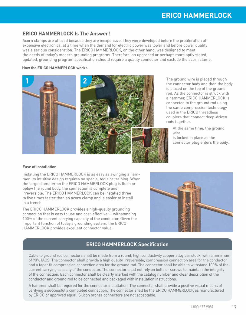
How the ERICO HAMMERLOCK works
Ease of Installation
The ground wire is placed through the connector body and then the body is placed on the top of the ground rod. As the connector is struck with a hammer, ERICO HAMMERLOCK is connected to the ground rod using the same compression technology used in the ERICO threadless couplers that connect deep-driven rods together.
At the same time, the ground wire is locked in place as the connector plug enters the body.
Installing the ERICO HAMMERLOCK is as easy as swinging a ham-mer. Its intuitive design requires no special tools or training. When the large diameter on the ERICO HAMMERLOCK plug is flush or below the round body, the connection is complete and irreversible. The ERICO HAMMERLOCK can be installed three to five times faster than an acorn clamp and is easier to install in a trench.
The ERICO HAMMERLOCK provides a high-quality grounding connection that is easy to use and cost-effective — withstanding 100% of the current carrying capacity of the conductor. Given the important function of today’s grounding system, the ERICO HAMMERLOCK provides excellent connector value.
ERICO HAMMERLOCK Specification
Cable to ground rod connectors shall be made from a round, high conductivity copper alloy bar stock, with a minimum of 90% IACS. The connector shall provide a high quality, irreversible, compression connection area for the conductor and a taper fit compression connection area for the ground rod. The connector shall be able to withstand 100% of the current carrying capacity of the conductor. The connector shall not rely on bolts or screws to maintain the integrity of the connection. Each connector shall be clearly marked with the catalog number and clear description of the conductor and ground rod to be connected and packaged with installation instructions.
A hammer shall be required for the connector installation. The connector shall provide a positive visual means of verifying a successfully completed connection. The connector shall be the ERICO HAMMERLOCK as manufactured by ERICO or approved equal. Silicon bronze connectors are not acceptable.
1 2
ERICO HAMMERLOCK

18 www.erico.pentair.com
Ground Enhancement Material (GEM)
ERICO Ground Enhancement Material (GEM) is the effective, maintenance free, permanent, easy to use, and environmentally sensitive solution to your toughest grounding problems.
GEM is a low-resistance, non-corrosive, carbon-based superior conductive material that improves grounding effectiveness, especially in areas of poor conductivity such as rocky ground, mountain tops and sandy soil. GEM is also the answer in situations where ground rods can’t be driven or where limited land area makes adequate grounding difficult with conventional methods.
GEM contains portland cement, which sets within 3 days and fully cures within 28 days, to become a highly conductive concrete that performs in all soil conditions irrespective of the presence of water. GEM maintains a constant level of superior performance once cured that will not diminish over the life of the grounding system.
GEM comes in easy to use 25 lb (11.3 kg) bags or buckets that one person can install. GEM is maintenance-free and will never leach or wash away. A Material Safety Data Sheet (MSDS) is available on request.
• Dramatically reduces earth resistance and impedance measurements
• Maintains constant resistance for the life of the system once in its set form
• Performs in all soil conditions even during dry spells
• May reduce the size of the grounding system where conventional methods are unsatisfactory
• Fully sets within 3 days, fully cures within 28 days.
• Does not dissolve, decompose or leach out with time
• Non-corrosive
• Reduces vandalism and theft since conductors are hard to remove from concrete
• Easy-to-handle 25 lb (11.3 kg) bags or buckets
• Requires one person to install• Exceeds IEC® 62561-7 which
sets the benchmark for corrosion, leaching, sulfur content, and other environmental regulations
• MSDS sheet available upon request
Part Number Description
GEM25A 25-lb. (11.3 kg) bag with handles
GEM25ABKT 25-lb. (11.3 kg) plastic bucket with locking lid
Fast and Easy OrderingFor more information, contact your local ERICO sales representative for a quote. You can reference the GEM part numbers.
GEMGround Enhancement Material
Conforms to IEC 62561-7
GEM is environmentally sensitive
• Does not require periodic charging treatments or placement
• Does not require the continuous presence of water to maintain its conductivity
GEM is effective
GEM is easy to use
GEM is maintenance free GEM is permanent
19www.erico.pentair.com 1.800.677.9089
ERICO Ground Enhancement Material (GEM)
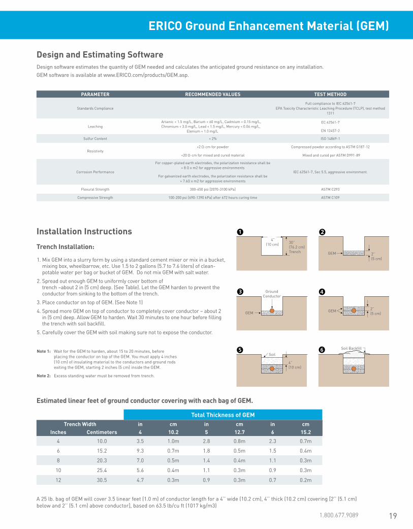
Design and Estimating SoftwareDesign software estimates the quantity of GEM needed and calculates the anticipated ground resistance on any installation. GEM software is available at www.ERICO.com/products/GEM.asp.
Estimated linear feet of ground conductor covering with each bag of GEM.
1. Mix GEM into a slurry form by using a standard cement mixer or mix in a bucket, mixing box, wheelbarrow, etc. Use 1.5 to 2 gallons (5.7 to 7.6 liters) of clean- potable water per bag or bucket of GEM. Do not mix GEM with salt water.
2. Spread out enough GEM to uniformly cover bottom of trench –about 2 in (5 cm) deep. (See Table). Let the GEM harden to prevent the conductor from sinking to the bottom of the trench.
3. Place conductor on top of GEM. (See Note 1)
4. Spread more GEM on top of conductor to completely cover conductor – about 2 in (5 cm) deep. Allow GEM to harden. Wait 30 minutes to one hour before filling the trench with soil backfill.
5. Carefully cover the GEM with soil making sure not to expose the conductor.
Note 1: Wait for the GEM to harden, about 15 to 20 minutes, before placing the conductor on top of the GEM. You must apply 4 inches (10 cm) of insulating material to the conductors and ground rods exiting the GEM, starting 2 inches (5 cm) inside the GEM.
Note 2: Excess standing water must be removed from trench.
Installation Instructions
Trench Installation:
A 25 lb. bag of GEM will cover 3.5 linear feet (1.0 m) of conductor length for a 4’’ wide (10.2 cm), 4’’ thick (10.2 cm) covering [2’’ (5.1 cm) below and 2’’ (5.1 cm) above conductor], based on 63.5 lb/cu ft (1017 kg/m3)
Total Thickness of GEMTrench Width in cm in cm in cm
Inches Centimeters 4 10.2 5 12.7 6 15.2
4 10.0 3.5 1.0m 2.8 0.8m 2.3 0.7m
6 15.2 9.3 0.7m 1.8 0.5m 1.5 0.4m
8 20.3 7.0 0.5m 1.4 0.4m 1.1 0.3m
10 25.4 5.6 0.4m 1.1 0.3m 0.9 0.3m
12 30.5 4.7 0.3m 0.9 0.3m 0.7 0.2m
2” (5 cm)
GEM
4” (10 cm)
SoilSoil Backfill
GEM
Ground Conductor
GEM 2” (5 cm)
30” (76.2 cm)Trench
4” (10 cm)
PARAMETER RECOMMENDED VALUES TEST METHOD
Standards ComplianceFull compliance to IEC 62561-7
EPA Toxicity Characteristic Leaching Procedure (TCLP), test method 1311
Leaching Arsenic < 1.5 mg/L, Barium < 60 mg/L, Cadmium < 0.15 mg/L, Chromium < 3.0 mg/L, Lead < 1.5 mg/L, Mercury < 0.06 mg/L, Elenium < 1.0 mg/L
EC 62561-7
EN 12457-2
Sulfur Content < 2% ISO 14869-1
Resistivity<2 Ω-cm for powder
<20 Ω-cm for mixed and cured material
Compressed powder according to ASTM G187-12
Mixed and cured per ASTM D991-89
Corrosion Performance
For copper-plated earth electrodes, the polarization resistance shall be > 8 Ω x m2 for aggressive environments
For galvanized earth electrodes, the polarization resistance shall be > 7.6Ω x m2 for aggressive environments
IEC 62561-7, Sec 5.5, aggressive environment.
Flexural Strength 300-450 psi [2070-3100 kPa] ASTM C293
Compressive Strength 100-200 psi [690-1390 kPa] after 672 hours curing time ASTM C109

20 www.erico.pentair.com
*8’ (2.4 m) minimum rod length required to be in contact with the soil (or GEM). Per NEC® 250-52
Note: To mix GEM into a slurry form, use a standard cement mixer or mix in a mixing box, wheelbarrow, etc. Use 1.5 to 2 gallons (5.7 to 7.6 liters) of clean-potable water per bag of GEM. Do not mix GEM with salt water. For storage and safety precautions, see product packaging.
Estimated bags of GEM for backfilling around ground rods to a density of 63.5 lb/ft3
Customer SupportSupport representatives are available to answer any product or application questions you may have; visit www.erico.pentair.com to find a phone number for your nearest customer support representative.
1. Auger a 3-inch (7.5 cm) or larger diameter hole to a depth of 6 inches (15 cm) shorter than the length of the ground rod.
2. Place ground rod into augered hole and drive 1 foot (30 cm) (if possible) into bottom of the hole. The top of the ground rod will be approximately 6 inches (15 cm) below grade. At this time, make any connections to ground rod using ERICO CADWELD connections. (See Note 1)
3. Premix GEM into a slurry form. Use 1.5 to 2 gallons (5.7 to 7.6 liters) of clean-potable water per bag or bucket of GEM. The installation of GEM in a dry state is acceptable for vertical ground rod applications.
4. Pour the appropriate amount of GEM (see table) around the ground rod. To ensure the GEM material completely fills the hole, tamp around the ground rod with a pole. Wait 30 minutes to 1 hour before filling the hole with soil backfill.
5. Fill remainder of augered hole with soil removed during augering. For various augered-hole diameters and depths, see the table below:
Note 1: 4 inches (10 cm) of insulating material must be applied to the conductors and ground rods exiting the GEM, starting 2 inches (5 cm) inside the GEM.
Note 2: Excess standing water must be removed from the hole.
Depth of Hole*Diameter of Hole ft m ft m ft m ft m ft m ft m
Inches Centimeters 5 1.5 6 1.8 8 2.4 10 3.0 15 4.6 20 6.1
4 10.2 2 2 2 3 4 5
6 15.2 3 3 4 5 8 10
8 20.3 5 6 8 9 14 18
10 25.4 7 9 12 14 21 28
12 30.5 10 12 16 20 30 40
ERICO Ground Enhancement Material (GEM)
Ground Rod Backfill Installation:
Auger Hole
6” (15.2 cm)
6” (15.2 cm)
Ground Rod
GEM packed around Ground Rod
Soil Backfill
Diameter
6” (15.2 cm) shorter than Ground Rod
12”(30.4 cm)
21www.erico.pentair.com 1.800.831.7133
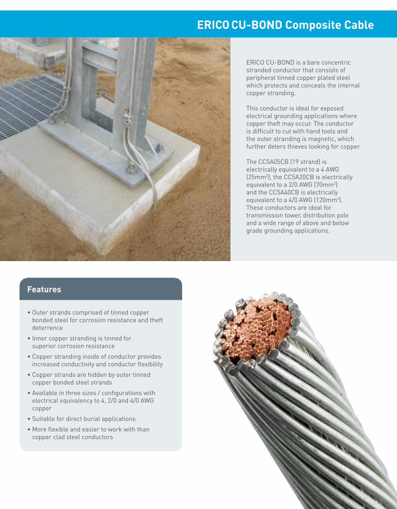
ERICO CU-BOND is a bare concentric stranded conductor that consists of peripheral tinned copper plated steel which protects and conceals the internal copper stranding.
This conductor is ideal for exposed electrical grounding applications where copper theft may occur. The conductor is difficult to cut with hand tools and the outer stranding is magnetic, which further deters thieves looking for copper.
The CC5A05CB (19 strand) is electrically equivalent to a 4 AWG (25mm2), the CC5A20CB is electrically equivalent to a 2/0 AWG (70mm2) and the CC5A40CB is electrically equivalent to a 4/0 AWG (120mm2). These conductors are ideal for transmission tower, distribution pole and a wide range of above and below grade grounding applications.
Features
• Outer strands comprised of tinned copper bonded steel for corrosion resistance and theft deterrence
• Inner copper stranding is tinned for superior corrosion resistance
• Copper stranding inside of conductor provides increased conductivity and conductor flexibility
• Copper strands are hidden by outer tinned copper bonded steel strands
• Available in three sizes / configurations with electrical equivalency to 4, 2/0 and 4/0 AWG copper
• Suitable for direct burial applications
• More flexible and easier to work with than copper clad steel conductors
ERICO CU-BOND Composite Cable

22 www.erico.pentair.com
For decades, ERICO has provided the market with high quality copper- bonded ground rods. ERICO has taken that same concept in ground rods and made this into a revolutionary new grounding conductor. The ERICO CU-BOND Round Conductor is comprised of an electro-plated coating of copper deposited over a layer of nickel surrounding a steel core. This process helps ensure a long-lasting molecular bond between the copper layer and the steel.
The conductor core consists of a low-carbon steel grade for improved flexibility in the field. The copper surface of the conductor provides high conductivity and corrosion-resistance properties.
ERICO CU-BOND Round Conductor
• Theft deterrent: Copper theft is a problem everywhere. ERICO CU-BOND Round Conductor is hard to cut with hand tools due to its steel core. They are also magnetic, notifying potential thieves that the materials within are of little scrap value.
• Cost-effective: Because the copper is bonded to a steel core, the cost of the conductor is minimized by reducing the total amount of copper in the cable.
• Copper-bonded coating will not crack or tear when the conductor is bent• High resistance to corrosion and provides a low resistance path to Earth• Available in standard packaging lengths of 100 meters, 50 meters, and 25 meters• Minimum copper plating thickness of 254 microns• Available in nominal diameters of 8, 10, 13, 14, 16, and 18 mm• Meets the requirements of IEC® 62305-3 Edition 2 and IEC/EN 62561-2 for lightning protection applications• ERICO CU-BOND Round conductors are UL certified to IEC® 62561-2
Features
Substation earthing riser
Equipotential grounding conductor
Benefits As An Alternative To Copper Conductor
GT ERICO CADWELD connection
• Superior corrosion resistance: In comparison to other steel-based products, ERICO CU-BOND Round Conductor provides excellent application life of typically 30-40 years in most soil conditions.
Benefits As An Alternative To Galvanized Steel Conductor

23www.erico.pentair.com 1.800.677.9089
ERICO CU-BOND Round Conductor
Above Grade ApplicationsThe unique properties of ERICO CU-BOND Round Conductor make it ideal for both horizontal and vertical placement. Above grade, the conductor is well-suited as a lightning- protection conductor when applied in accordance with the IEC 62305-3 Edition 2.0 standard.
• Utility -Distribution down-lead conductor and assemblies -Bonding kits for substation fence or equipment ground risers back to the grid
• Commercial and Industrial - Alternative conductors to solid copper rod and tapes
in grounding and lightning protection
• Telecom - Conductor for connecting equipment ground to ground
grid, and riser (down-lead) conductors for tower -Grounding conductor for datacenter mesh bonding
• Rail -Trackside bonding conductor and stray current conductor - Grounding kits for trackside equipment, electrical
traction power - Substation, wayside shelters, communication
antenna equipment
Lightning protection
Below Grade Applications
• Buried ground grid conductors and electrodes:
-Wireless telecom tower earthing
-Utility substation earthing; power distribution and transmission earthing
-Large scale ground mount solar farm earthing
- Industrial facility earthing, for example, petro-chemical and mining infrastructure
-Railway earthing
• Interconnecting grounding conductor between wind towers or grounding grid at base of wind tower
Copper-bonded steel conductors are ideal as earthing and bonding conductors where copper theft on-site may occur. ERICO CU-BOND is ideal for use in a variety of applications including power distribution earthing and bonding; substation earthing; commercial, industrial, and railway earthing.
Telecom tower grounding
ERICO CU-BOND Round Conductor is stamped with compliance markings directly on the product to ensure genuine product and high quality standards. Beware of imitations.
24 www.erico.pentair.com
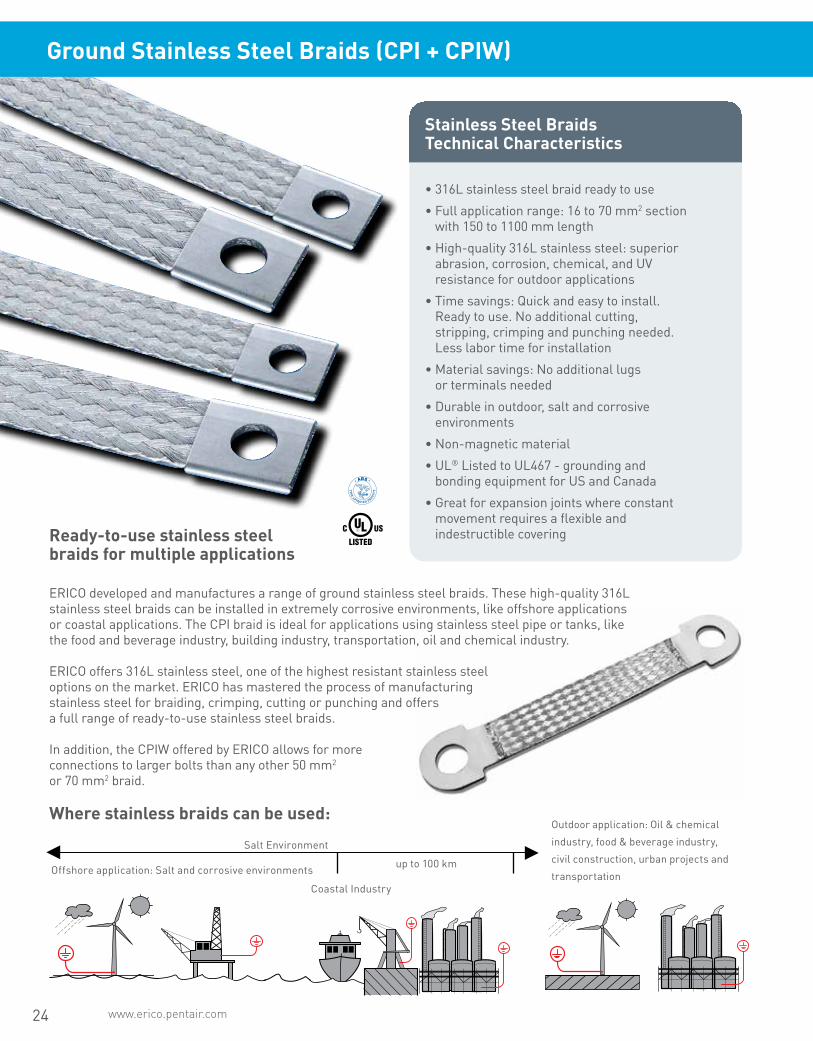
• 316L stainless steel braid ready to use
• Full application range: 16 to 70 mm2 section with 150 to 1100 mm length
• High-quality 316L stainless steel: superior abrasion, corrosion, chemical, and UV resistance for outdoor applications
• Time savings: Quick and easy to install. Ready to use. No additional cutting, stripping, crimping and punching needed. Less labor time for installation
• Material savings: No additional lugs or terminals needed
• Durable in outdoor, salt and corrosive environments
• Non-magnetic material
• UL® Listed to UL467 - grounding and bonding equipment for US and Canada
• Great for expansion joints where constant movement requires a flexible and indestructible covering
Stainless Steel Braids Technical Characteristics
Ready-to-use stainless steel braids for multiple applications
Where stainless braids can be used:
ERICO developed and manufactures a range of ground stainless steel braids. These high-quality 316L stainless steel braids can be installed in extremely corrosive environments, like offshore applications or coastal applications. The CPI braid is ideal for applications using stainless steel pipe or tanks, like the food and beverage industry, building industry, transportation, oil and chemical industry.
ERICO offers 316L stainless steel, one of the highest resistant stainless steel options on the market. ERICO has mastered the process of manufacturing stainless steel for braiding, crimping, cutting or punching and offers a full range of ready-to-use stainless steel braids.
In addition, the CPIW offered by ERICO allows for more connections to larger bolts than any other 50 mm2 or 70 mm2 braid.
Salt Environment
Outdoor application: Oil & chemical
industry, food & beverage industry,
civil construction, urban projects and
transportationup to 100 km
Coastal Industry
Offshore application: Salt and corrosive environments
Ground Stainless Steel Braids (CPI + CPIW)
25www.erico.pentair.com 1.800.677.9089
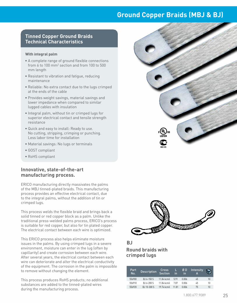
Tinned Copper Ground Braids Technical Characteristics
• A complete range of ground flexible connections from 6 to 100 mm2 section and from 100 to 500 mm length
• Resistant to vibration and fatigue, reducing maintenance
• Reliable: No extra contact due to the lugs crimped at the ends of the cable
• Provides weight savings, material savings and lower impedance when compared to similar lugged cables with insulation
• Integral palm, without tin or crimped lugs for superior electrical contact and tensile strength resistance
• Quick and easy to install: Ready to use. No cutting, stripping, crimping or punching. Less labor time for installation
• Material savings: No lugs or terminals
• GOST compliant
• RoHS compliant
With integral palm
Innovative, state-of-the-art manufacturing process.
Round braids with crimped lugs
ERICO manufacturing directly massivates the palms of the MBJ tinned-plated braids. This manufacturing process provides an effective electrical contact, due to the integral palms, without the addition of tin or crimped lugs.
This process welds the flexible braid and brings back a solid tinned or red copper block as a palm. Unlike the traditional press-welded palms process, ERICO’s process is suitable for red copper, but also for tin plated copper. The electrical contact between each wire is optimized.
This ERICO process also helps eliminate moisture issues in the palms. By using crimped lugs in a severe environment, moisture can enter in the lug (often by capillarity) and create corrosion between each wire. After several years, the electrical contact between each wire can deteriorate and alter the electrical conductivity of the equipment. The corrosion in the palm is impossible to remove without changing the element.
This process produces RoHS products; no additional substances are added to the tinned-plated wires during the manufacturing process.
BJ
Part No. Description Cross
SectionL in
Ø D in
IntensityA
556900 BJ 6-150 S 11.84 kcmil 5.91 0.006 45 10556910 BJ 6-200 S 11.84 kcmil 7.87 0.006 45 10556920 BJ 10-300 S 19.74 kcmil 11.81 0.006 75 10
Ground Copper Braids (MBJ & BJ)
www.erico.pentair.com26
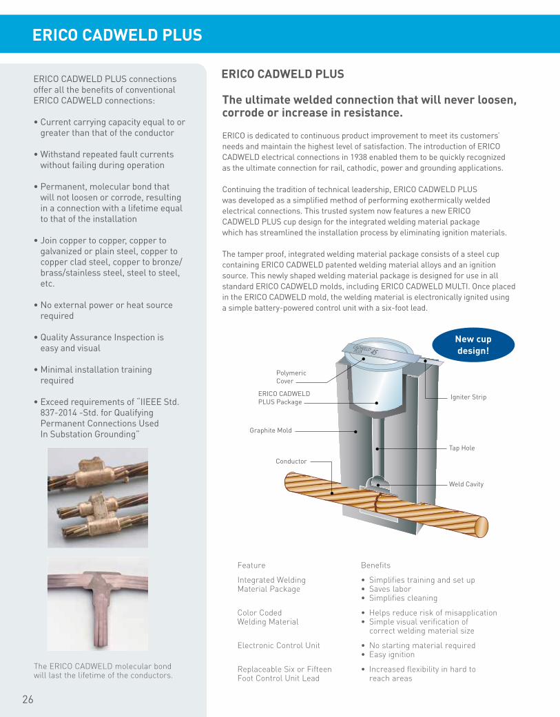
Polymeric Cover
Igniter Strip
Tap Hole
Weld Cavity
ERICO CADWELD PLUS Package
Graphite Mold
Conductor
New cup design!
The ultimate welded connection that will never loosen, corrode or increase in resistance.
ERICO is dedicated to continuous product improvement to meet its customers’ needs and maintain the highest level of satisfaction. The introduction of ERICO CADWELD electrical connections in 1938 enabled them to be quickly recognized as the ultimate connection for rail, cathodic, power and grounding applications.
Continuing the tradition of technical leadership, ERICO CADWELD PLUS was developed as a simplified method of performing exothermically welded electrical connections. This trusted system now features a new ERICO CADWELD PLUS cup design for the integrated welding material package which has streamlined the installation process by eliminating ignition materials.
The tamper proof, integrated welding material package consists of a steel cup containing ERICO CADWELD patented welding material alloys and an ignition source. This newly shaped welding material package is designed for use in all standard ERICO CADWELD molds, including ERICO CADWELD MULTI. Once placed in the ERICO CADWELD mold, the welding material is electronically ignited using a simple battery-powered control unit with a six-foot lead.
ERICO CADWELD PLUS connections offer all the benefits of conventional ERICO CADWELD connections: • Current carrying capacity equal to or
greater than that of the conductor
• Withstand repeated fault currents without failing during operation
• Permanent, molecular bond that will not loosen or corrode, resulting in a connection with a lifetime equal to that of the installation
• Join copper to copper, copper to galvanized or plain steel, copper to copper clad steel, copper to bronze/ brass/stainless steel, steel to steel, etc.
• No external power or heat source required
• Quality Assurance Inspection is easy and visual
• Minimal installation training required
• Exceed requirements of “IIEEE Std. 837-2014 -Std. for Qualifying Permanent Connections Used In Substation Grounding”
The ERICO CADWELD molecular bond will last the lifetime of the conductors.
Feature Benefits
Integrated Welding • Simplifies training and set up Material Package • Saves labor • Simplifies cleaning Color Coded • Helps reduce risk of misapplicationWelding Material • Simple visual verification of correct welding material size
Electronic Control Unit • No starting material required • Easy ignition
Replaceable Six or Fifteen • Increased flexibility in hard toFoot Control Unit Lead reach areas
ERICO CADWELD PLUS
ERICO CADWELD PLUS

27www.erico.pentair.com 1.800.677.9089
Installation Is Easy! 4 Simple Steps For Permanently Welded Electrical Connections
• Consists of a tamper proof, disposable, moisture-resis-tant welding material cup. The welding material, disk and ignition source are incorporated into the self-con-tained package
• Long shelf life
• Completes welds at distances of up to 6 ft/1.8 meters (up to 15 ft/4.6 meters with optional lead)
• Requires minimum components – no starting material, no disks, no flint igniters
• Easy to handle, store and transport – by air, land or sea in unlimited quantities
• Reduces installation time by 20%
• Has color-coded welding material containers – by size and alloy type – for easy identification
• Has electronic ignition with a CE/UL battery powered controller box that is designed for 600 connections with one set of 8 standard AA batteries (included) – requiring no special batteries or chargers
• Designed for use in standard ERICO CADWELD molds including ERICO CADWELD MULTI
Insert ERICO CADWELD PLUS cup into mold (may require use of a cover/baffle)
Press and hold control unit switch and wait for the ignition
Attach control unit termination clip to ignition strip
Open the mold and remove the expended steel cup – no special disposal required
ERICO CADWELD PLUS Control Unit initiates the reaction of the metal crucible. The standard unit includes a 6-foot (1.8 meter) high temperature control unit lead. The lead attaches to the ignition strip using a custom made, purpose-designed termination clip.
After the termination clip is installed on the ignition strip, the installer pushes and holds the ignition button to start a charging and discharging sequence. Within a few seconds the control unit sends a predetermined voltage to the ignition strip and the reaction is initiated.
ERICO CADWELD PLUS
1 2
43
Self contained welding material package
28 www.erico.pentair.com
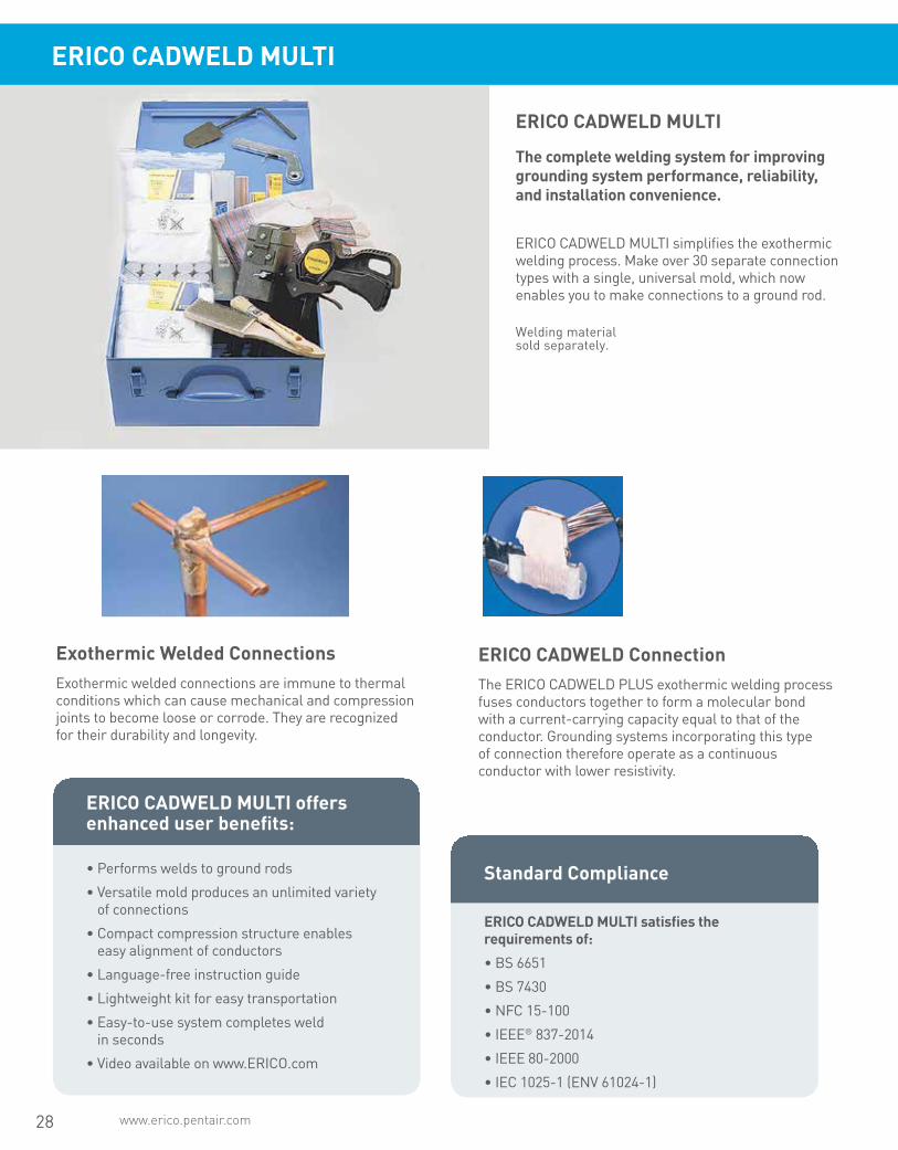
ERICO CADWELD MULTI
Exothermic Welded ConnectionsExothermic welded connections are immune to thermal conditions which can cause mechanical and compression joints to become loose or corrode. They are recognized for their durability and longevity.
ERICO CADWELD ConnectionThe ERICO CADWELD PLUS exothermic welding process fuses conductors together to form a molecular bond with a current-carrying capacity equal to that of the conductor. Grounding systems incorporating this type of connection therefore operate as a continuous conductor with lower resistivity.
The complete welding system for improving grounding system performance, reliability, and installation convenience.
ERICO CADWELD MULTI simplifies the exothermic welding process. Make over 30 separate connection types with a single, universal mold, which now enables you to make connections to a ground rod.
ERICO CADWELD MULTI
Welding material sold separately.
• Performs welds to ground rods
• Versatile mold produces an unlimited variety of connections
• Compact compression structure enables easy alignment of conductors
• Language-free instruction guide
• Lightweight kit for easy transportation
• Easy-to-use system completes weld in seconds
• Video available on www.ERICO.com
ERICO CADWELD MULTI offers enhanced user benefits:
Standard Compliance
ERICO CADWELD MULTI satisfies the requirements of:
• BS 6651
• BS 7430
• NFC 15-100
• IEEE® 837-2014
• IEEE 80-2000
• IEC 1025-1 (ENV 61024-1)

www.erico.pentair.com 1.800.677.9089 29
ERICO CADWELD MULTI combines a versatile mold block and a range of gaskets (batting) to allow numerous different welded connections to be produced without the need to change the mold for each connection type
The process is similar to the ERICO CADWELD with one distinct difference...
there is no need to change the mold for different connection types.
The whole process is complete in about one minute. Page 31 details the gasket quantities required for each weld.
How Does It Work?4 Easy steps for multiple, permanently welded,
electrical connections
Step 1: Layer batting and variable conductor sizes to be welded into dry mold.
Step 2: Add ERICO CADWELD PLUS welding material.
Step 3: Close cover and connect ERICO CADWELD PLUS control unit.
Step 4: Press and hold operate button. Open mold after 10 seconds.
ERICO CADWELD MULTI

30 www.erico.pentair.com
TG
GT
CP
CN
TA PG
PK
SS
RF
XA
ERICO CADWELD MULTI
ERICO CADWELD MULTI offers all of the benefits of ERICO CADWELD connections:
• Current-carrying capacity equal to that of the conductor
• Permanent molecular bond that will not loosen or corrode
• Works with ERICO CADWELD traditional welding material
• Works with ERICO CADWELD PLUS welding material
• Will withstand repeated fault currents
• No external power or heat required
• Ground rod capabilities
• Visual inspection possible
• Requires minimal training

31www.erico.pentair.com 1.800.677.9089
ERICO CADWELD MULTI
ERICO CADWELD MULTI Connection Capabilities
Copper Cable/Solid Strip to Rebar
RG RH RK RF RD• Copper concentric conductor sizes up to 50 mm2 (9.3 mm dia.) or 1/0 AWG (0.37” dia.)• Copper or steel strip sizes up to 30 x 3,5 mm (1.2” x 0.14”)• Rebar sizes up to 10 mm (#3)
Copper Strip to Copper Strip
BB CG BG EB• BB and CG: Copper strip sizes up to 30 x 3,5 mm (1.2” x 0.14”)• BG and EB: Copper strip sizes up to 30 x 3,0 mm (1.2” x 0.12”)
Copper Cable/Solid to Copper or Steel Strip/Lug
HA HC HS HT GL LA LJ LE• Copper concentric conductor sizes up to 50 mm2 (9.3 mm dia.) or 1/0 AWG (0.37” dia.)• Copper or steel lug / strip sizes up to 30 x 3,5 mm (1.2” x 0.14”)
Galvanized Steel Strip to Galvanized Steel Strip
BB CG• Galvanized steel strip sizes up to 30 x 3,5 mm (1.2” x 0.14”)
NOTES:•* For connections using a 3/4” ground rod, it is necessary to use #115 / 115PLUSF20 weld material (sold separately).
• For all other connection types, use #90 or 90PLUSF20.
• For connections using galvanized material, remove galvanizing before welding, for a better connection.
Ground Rod Connections
TG GT CN CP GR GT CN CP GR
Part Nr Article Nr Description Weight (kg) KITCDMV01 167782 CADWELD MULTI Kit 1 25.000 The CADWELD MULTI kit (KITCDMV01) contains the following list of items: FMCDMV01 120883 Handle Clamp 1 1.800 CDMV01H 240399 Mold for H welds 1 1.200 CDMV0112 240398 Mold for welds on 1/2 rods 1 1.200 CDMV0158 240397 Mold for welds on 5/8 rods 1 1.200 CDMV0134 240396 Mold for welds on 3/4 rods* 1 1.200 SCDM01 120886 Set of 33 batting/gaskets 2 0.200 B399P 162070 SKK1 clamp 1 0.500 TSCSTP 197295 Toolset 1 2.000 B136B 182030 Slag Removal Spade 1 0.144 Language free instruction sheet 1 The following items can be used with the CADWELD MULTI Kit (KITCDMV01). They are sold separately. T320 165000 Flint Ignitor T320 1 0.090 90 163040 CADWELD Traditional welding material 10 0.090 115 163050 CADWELD Traditional welding material 10 0.115 PLUSCU 165745 Control Unit 1 1.088 PLUS#90F20 165705 CADWELD PLUS welding material 10 0.158
Symbol denotes number of batting (gaskets) required for each connection.
Requires 3 batting layers for weld
Requires 2 batting layers for weld
• Copper concentric conductor sizes up to 10 mm2 (4.2 mm dia.) or #6 AWG (0.18” dia.) • Copper strip sizes up to 30 x 2,0 mm (1.2” x 0.08”
Copper Cable/Solid to Copper Cable/Solid
SS SC PA TA XA GG GJ TD TE TF
GF GW XB PP PK GE PG• Copper concentric conductor sizes up to 50 mm2 (9.3 mm dia.) or 1/0 AWG (0.37” dia.)
• Copper concentric conductor sizes up to 25 mm2 (6.6 mm dia.) or #3 AWG (0.26” dia.)
• Copper concentric conductor sizes greater than 10 mm2 (4.2 mm dia.) or #6 AWG (0.18” dia.) • Copper strip sizes 30 x (2,5 - 3,0 mm) or 1.2” x (0.10” – 0.12”) • Steel strip sizes 30 x (0,5 - 3,5 mm) or 1.2” x (0.02” – 0.14”
ERICO CADWELD MULTI Available Items

32 www.erico.pentair.com
ERICO CADWELD ONE SHOT
ERICO CADWELD ONE SHOT produces a permanent exothermic connection to a ground rod that will not loosen, corrode or increase in resistance for the life of the installation. The convenient single-use package makes the connection to the ground rod without a mold or starting material.
Thanks to the electronic ERICO CADWELD ONE SHOT Control Unit, welds can now be completed up to 6 ft. (1.8 m) away, increasing weld flexibility in hard-to reach areas. The refractory ceramic body on the ERICO CADWELD ONE SHOT is more durable than conventional ceramic and resists breaking.
Permanent Exothermic Connections without the Mold
Installation is easy!
1. After preparing the ground rod and wire, position the ERICO CADWELD ONE SHOT and attach the lead to the control unit.
2. Ignite the ERICO CADWELD ONE SHOT with the electronic CADWELD PLUS Control Unit.
3. After one minute, break off the ceramic crucible. It can also be left in place, if desired.
• Easy-to-use electronic ignition. No starting material needed
• Extremely durable disposable ceramic outer body eliminates the graphite mold and frame
• Produces a permanent connection that will not loosen or corrode
• Fits both plain and threaded copper-bonded and full-size steel and stainless steel ground rods
• NEC® compliant
• cULus® Listed
Features:

33www.erico.pentair.com 1.800.677.9089
This catalog lists the most popular ERICO CADWELD connections using solid or concentric stranded copper conductor, insulated or bare. Look in the index for the connection you need. To save time and money, avoid non-catalog items or specials whenever possible.
If you cannot find the connection you need, contact ERICO or your local distributor or agent. We have designed over 45,000 connections, and “specials” are designed every day.
How to order ERICO CADWELD products
1. What connection do you want?
3. What are the conductor sizes?
4. You must have the following to make a weld:
2. Only the most popular ERICO CADWELD connections are listed in this catalog.
We strongly recommend that wherever possible you use molds listed in this catalog. After selecting the connection, turn to the appropriate page and select the mold, weld metal and tools you need.
This catalog covers connections between solid or concentric stranded copper conductors to each other, to lugs, to ground rods, to rebar, to rail and to special grounding accessories. For sizes not listed, contact your local ERICO CADWELD distributor, agent, or ERICO.
4.1 Mold to fit your conductors
4.2 Weld metal required by your mold
4.3 Handle clamps on frame
4.4 Flint ignitor (included with handle clamps and frames)
4.5 If using ERICO CADWELD EXOLON, you need a Relia-Start™ battery instead of a flint ignitor.
4.6 Lugs, sleeves, packing material listed on the page with the mold.
For a complete listing of ERICO CADWELD EXOLON connections, please refer to pentair.erico.com or your local ERICO representative.
Note: Other publications describe connections to conductors of copperclad, high voltage copper, aluminum, busbar, lightning protection cable, steel cable, etc.
ERICO CADWELD
34 www.erico.pentair.com
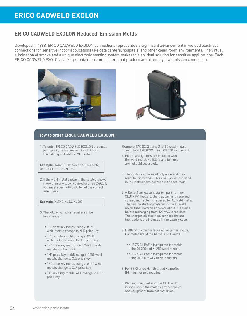
ERICO CADWELD EXOLON
Developed in 1988, ERICO CADWELD EXOLON connections represented a significant advancement in welded electrical connections for sensitive indoor applications like data centers, hospitals, and other clean room environments. The virtual elimination of smoke and a unique electronic starting system makes this an ideal solution for sensitive applications. Each ERICO CADWELD EXOLON package contains ceramic filters that produce an extremely low emission connection.
ERICO CADWELD EXOLON Reduced-Emission Molds
How to order ERICO CADWELD EXOLON:
1. To order ERICO CADWELD EXOLON products, just specify molds and weld metal from the catalog and add an “XL” prefix.
Example: TAC2Q2Q becomes XLTAC2Q2Q, and 150 becomes XL150.
2. If the weld metal shown in the catalog shows more than one tube required such as 2-#200, you must specify #XL400 to get the correct size filters.
Example: XLTAD-4L3Q: XL400
3. The following molds require a price key change:
• “C” price key molds using 2-#150 weld metals change to XLD price key.
• “E” price key molds using 2-#150 weld metals change to XLJ price key.
• “H” price key molds using 2-#150 weld metals, contact ERICO.
• “M” price key molds using 2-#150 weld metals change to XLV price key.
• “R” price key molds using 2-#150 weld metals change to XLF price key.
• “T” price key molds, ALL change to XLP price key.
Example: TAC3Q3Q using 2-#150 weld metals change to XLTAD3Q3Q using #XL300 weld metal
4. Filters and ignitors are included with the weld metal. XL filters and ignitors are not sold separately.
5. The ignitor can be used only once and then must be discarded. Filters will last as specified in the instructions supplied with each mold.
6. A Relia-Start electric starter, part number XLB971A1 (battery, charger, carrying case and connecting cable), is required for XL weld metal. Ther eis no starting material in the XL weld metal tube. Batteries operate about 200 starts before recharging from 120 VAC is required. The charger, all electrical connections and instructions are included in the battery case.
7. Baffle with cover is required for larger molds. Estimated life of the baffle is 500 welds.
• XLB972A1 Baffle is required for molds using XL200 and XL250 weld metals.
• XLB973A1 Baffle is required for molds using XL300 to XL750 weld metals.
8. For EZ Change Handles, add XL prefix. (Flint ignitor not included.)
9. Welding Tray, part number XLB974B2, is used under the mold to protect cables and equipment from hot materials.
35www.erico.pentair.com 1.800.677.9089
ERICO CADWELD
Other information
Certain tools may be required for various connections. If required, these tools are listed on the same pages as the connection and in Section A. Some tools in section A can save you a lot of time. Also refer to A9E, Contractor Tips, to make your job easier, and learn about labor saving ideas.
For complete pricing information, please visit pentair.erico.com or contact and ERICO Representative
For ERICO CADWELD literature, guides, instructional videos, and more, visit erico.pentair.com.
For all your connection needs — we’re only a phone call away.
Phone: 800-677-9089
Fax: 800-677-8131
or call your local ERICO CADWELD distribort, agent, or ERICO CADWELD regional sales manager
Required tools summary:
Required tools are listed with each mold. For your reference, handle clamps and/or frame are summarized below.
Mold RequiredA* Includes frame with handle
C, Q & R Requires L160
D, F & Z Requires L159
E* Includes frame but also requires L160
J* Includes frame but also requires L159
K*, M* & V* Includes frame with handles
* To order mold only — without handles or frame — add suffix “M” to mold part number.
Heavy Duty connections were developed to be used on reclaimd cable. Heavy Duty connections use a larger size connection cavity in the mold and a larger size weld metal than the equivalent standard connections.
The larger size weld metal supplies extra BTU’s (but not a higher temperature) to melt the heavy oxide coating on the conductor and to overcome severe field conditions.
Heavy Duty connections offer the following advantages:
• Eliminates cutting the run conductor on certain types of connections.
• Reduces cable cleaning requirements for old or reclaimed cable.
• Increases reliability under adverse field conditions.
Heavy Duty Electrical Connections for Stranded Concentric Copper Conductors

36 www.erico.pentair.com
ERICO CADWELD
Grounding Connection Specification
This specification covers the ERICO CADWELD exothermic welding system for use in making electrical connections. The ERICO CADWELD system supplied under this specification shall include welding material, molds, tools and accessories as required.
Unless otherwise specified, ERICO CADWELD exothermic welding system shall be used for all electrical grounding connections of copper to copper and copper to steel conductors. ERICO CADWELD connections shall be suitable for exposure to the elements of direct burial in earth or concrete without degradation over the lifetime of the grounding system.
The ERICO CADWELD exothermic welding system furnished under this specification shall meet the applicable requirements of IEEE Standard 80 “IEEE Guide for Safety in AC Substation Grounding” and IEEE Standard 837 IEEE “Standard for Qualifying Permanent Connections Used in Substation Grounding”. Independent test data showing conformance to IEEE Std. 837 shall be readily available.
The ERICO CADWELD mold part number gives, in code, the complete information about the mold.
Type of connection, mold price key, and conductor size(s)
X X X - X X X X
Examples:
Mold Type Code forMain or Run Conductor
Mold PriceKey
Code for TapConductor
SSC-3D
Type SS
350 kcmil Tap
Price Key C
TAD-4L3Q
Type TA
750 kcmil Run
Price Key D
500 kcmil Tap
GTC-18 2V
Type GT
3/4” Copper
Clad Ground
Rod
Price Key C
250 kcmil Tap
VSC-2C-V3
Type VS
1/0 Cable
Price Key C
3” IPS
The ERICO CADWELD Mold Numbering System
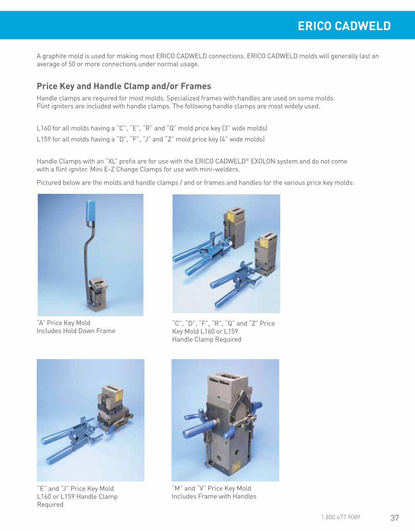
37www.erico.pentair.com 1.800.677.9089
ERICO CADWELD
A graphite mold is used for making most ERICO CADWELD connections. ERICO CADWELD molds will generally last an average of 50 or more connections under normal usage.
Handle clamps are required for most molds. Specialized frames with handles are used on some molds. Flint igniters are included with handle clamps. The following handle clamps are most widely used.
L160 for all molds having a “C”, “E”, “R” and “Q” mold price key (3” wide molds)
L159 for all molds having a “D”, “F”, “J” and “Z” mold price key (4” wide molds)
Handle Clamps with an “XL” prefix are for use with the ERICO CADWELD® EXOLON system and do not come with a flint igniter. Mini E-Z Change Clamps for use with mini-welders.
Pictured below are the molds and handle clamps / and or frames and handles for the various price key molds:
Price Key and Handle Clamp and/or Frames
“A” Price Key Mold Includes Hold Down Frame
“M” and “V” Price Key Mold Includes Frame with Handles
“C”, “D”, “F”, “R”, “Q” and “Z” Price Key Mold L160 or L159 Handle Clamp Required
“E” and “J” Price Key Mold L160 or L159 Handle Clamp Required
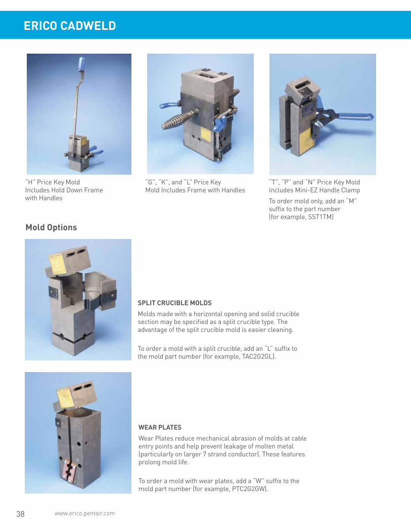
38 www.erico.pentair.com
SPLIT CRUCIBLE MOLDS
Molds made with a horizontal opening and solid crucible section may be specified as a split crucible type. The advantage of the split crucible mold is easier cleaning.
To order a mold with a split crucible, add an “L” suffix to the mold part number (for example, TAC2G2GL).
WEAR PLATES
Wear Plates reduce mechanical abrasion of molds at cable entry points and help prevent leakage of molten metal (particularly on larger 7 strand conductor). These features prolong mold life.
To order a mold with wear plates, add a “W” suffix to the mold part number (for example, PTC2G2GW).
“H” Price Key Mold Includes Hold Down Frame with Handles
“G”, “K”, and “L” Price Key Mold Includes Frame with Handles
“T”, “P” and “N” Price Key Mold Includes Mini-EZ Handle Clamp
To order mold only, add an “M” suffix to the part number (for example, SST1TM)
Mold Options
ERICO CADWELD

39www.erico.pentair.com 1.800.677.9089
Since 1903, ERICO has been a partner in building global industry and infrastructure. Today, we continue that tradition by offering industry leading products in addition to value-added solutions.
As of 2015, ERICO is now a Pentair company in an effort to continue serving our customers as effectively as possible. Visit our website below for more information.erico.pentair.com
ERICO and PentairCustomized solutions for modern industry.
SUPERIORSOLUTIONSOver a century of industry experience
Representatives across the US and Globe
Complimentary design and engineering services
Complete facility electrical protection solutions
And more

40 www.erico.pentair.com
Grounding, Bonding & Connectivity Products
ERICO offers a full range of grounding, bonding and connectivity products for data centers and other data-com applications worldwide. ERICO’s product offerings include grounding and bonding accessories, surge protection and lightning protection products, and welded electrical connections.
ERICO Facility Electrical Protection
ERICO offers an extensive line of ground-ing and bonding products, which includes ground rods and accessories, signal reference grids, chemical ground rods, GEM ground enhancement material, couplers, clamps, inspection wells, grounding and perimeter bus bars and ground test instruments.
Grounding and Bonding
ERICO CADWELD welded electrical connections are used to connect the grounding and bonding conductors to each other and to the ground electrode system, including ground rod electrodes, building steel and rebar. ERICO CADWELD connections provide a permanent, low-resistance connection needed to create a long- lasting, reliable bonding network. ERICO CADWELD connections will not deteriorate, cannot loosen and are made with inexpensive, lightweight and portable equipment. ERICO CADWELD EXOLON is a filtered, smokeless connection system designed for making connections indoors.
Welded Electrical Connections
Direct and indirect lightning strikes can pose many risks to businesses, includ-ing damaging buildings and critical equipment. ERICO lightning protection products offer a variety of solutions to help protect valuable equipment and personnel and to avoid disruption and downtime.
Lightning Protection
ERICO surge protection products are designed to protect against damaging electrical surges on power and commu-nications lines caused by lightning, build-ing systems and other switching events.
Surge Protection
C ERICO CADWELD Through Connection to Pedestal (VG)
D ERICO CADWELD Connection to SRG (HA)
A Universal Pedestal Clamp (MBNUPCJ82, MBNUPCJ240)
B ERICO CADWELD Connection to Pedestal (VS)
Signal Reference Grid (SRG)
Lightning Protection Cable
Telecommunications Ground Bar (TGB) and CADWELD Lugs
Lightning Air Terminals
ERICO CADWELD Lugs
Pedestal Bonding Options
D
A
B C
Low Impedance Riser (LIR) Common Bonding
Network Jumper (CBNJ09)
Cable Runway Ground Strap (CRGS6)

41www.erico.pentair.com 1.800.677.9089
For Datacom Applications
The SRG is an integrated high-frequency, low-imped-ance signal reference grid structure, which consists of a network of flat copper strips welded at the cross-overs in accordance with recommendations found in IEEE® 1100 “IEEE Recommended Practice for Powering and Grounding Electronic Equipment.” The SRG is also referred to as a “Supplementary Bonding Grid” (SBG) per TIA® 607.
The SRG lies directly on the sub-floor under the raised-floor structure and is used to interconnect metal frames, racks, enclosures, common terminals for signal level power and the electrical distribution grounding system. The SRG is used as a ground reference system for IT equipment by creating an equipotential ground reference plane over a large range of frequencies from DC through the Megahertz range. At high frequencies, flat strip conductors have considerably lower inductive reactance than concen-tric stranded or solid conductors and the configura-tion of the SRG results in a lower impedance system, which limits potential differences between data systems and other systems during voltage transients or other power system disturbances. The following graph from IEEE 1100 shows the impedance of an SRG system versus a wire-only grounding system.
SRG IMPEDANCE VS. FREQUENCY
0
20
40
60
80
100
120
140
160
180
200
0.0 1.0 2.0 3.0 4.0 5.0 6.0 7.0
Frequency in MHz
SRG Impedance
Wire Only Impedance
Imp
edan
ce in
Oh
ms
• Economical and maintenance-free
• Recommended in IEEE® 1100
• Reduces common-mode noise
• Increases noise immunity to electric fields
• Reduces capacitive coupled interference
• Compliant with Information Technology Industry Council Information Letter “Guidelines For Ground-ing Information Technology Equipment (ITE)” and the National Electrical Code.
SRG Features and Benefits
Prefabricated Signal Reference Grid (SRG)
IEEE is a registered trademark of The Institute of Electrical and Electronics Engineers, Incorporated.
TIA is a copyright of Telecommunications Industy Association
1
Universal Pedestal Clamp (MBNUPCJ82, MBNUPCJ240) 2
3
4
5
1
4
25
3
Cable-to-Lug (GL)
Cable-to-Ground Rod (GT)
Cable-to-Rebar (RH)
Cable-to-Cable (PT)
Cable-to-Steel (VF)
Telecommunications Main Ground Bar (TMGB) and CADWELD Lugs
Water/Gas Pipe Clamp
Rebar ClampsCAT 6 Network Surge Protector
Coaxial Surge Protector
Subscriber/High Speed Line Surge Protector
Power Surge Protection
Ground Rods
ERICO CADWELD CONNECTIONS
NOTE: ERICO CADWELD connections shown are typical. Connections for any configuration and conductor are available to meet specific application requirements.

42 www.erico.pentair.com
Power Generation Facilities
Traditional power generation facilities have either been coal-fired, gas-fired, nuclear, diesel or hydro-powered. Modern alternative power generation facilities can include geothermal, bio-gas, wind or solar. ERICO brand of lightning protection systems have been used to provide lightning protection to the whole host of facilities in a unique manner. ERICO grounding and bonding solutions can provide a complete system for the grounding and bonding of any of these facilities.
Power Generation Plant
ERICO SYSTEM 2000 Conventional Lightning Air
Terminal
Lightning Downconductor
Inspection Well
Ground Grid (Equipotential Bonding)
Fence and Gate Jumper Assemblies
ERICO SYSTEM 3000 Lightning Protection
Surge Protection
ERICO CADWELD Connections
Ground Enhancement Material (GEM)
Copper-bonded Ground Rods
ERICO CADWELD Structure Connections
Power Generation
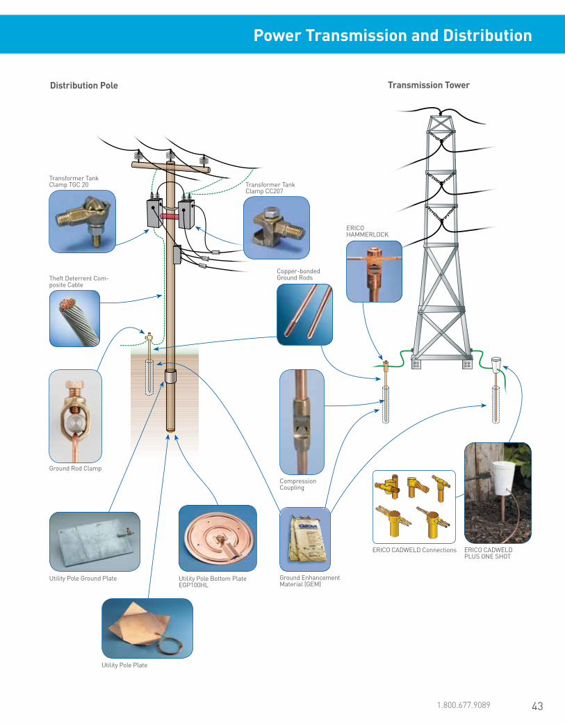
43www.erico.pentair.com 1.800.677.9089
Power Transmission and Distribution
Distribution Pole Transmission Tower
ERICO CADWELD Connections
Copper-bonded Ground Rods
ERICO HAMMERLOCK
Ground Enhancement Material (GEM)
Theft Deterrent Com-posite Cable
Utility Pole Bottom Plate EGP100HL
Utility Pole Ground Plate
Utility Pole Plate
ERICO CADWELD PLUS ONE SHOT
Compression Coupling
Ground Rod Clamp
Transformer Tank Clamp TGC 20 Transformer Tank
Clamp CC207

44 www.erico.pentair.com
Copper Cable
Soil
Crushed Rock
GT
The conceptual design of a ground grid at a substation is summarized by the points below and depicted on pages 4 and 5.
a) A continuous loop conductor should surround the perimeter to enclose as much area as practical. Under Standard IEEE® 80, this loop conductor is placed 3 ft (or 1 meter) outside the fence line. This measure helps to avoid high current concentration and high gradients both in the grid area and near the projecting cable ends. Enclosing more area also reduces the resistance of the grounding grid.
b) Within the substation, conductors are typically laid in a parallel grid and, where practical, along the structures or rows of equipment to provide for short ground connections.
c) A typical grid system for a substation may include bare copper conductors buried 18” (0.5 m) below grade, spaced 9 ft to 21 ft (3 m to 7 m) apart, in a grid pattern. At cross-connections, the conductors would be securely bonded together. Ground rods may be at the grid corners and at junction points along the perimeter.
d) This grid system would be extended over the entire substation switchyard and beyond the fence line.
Earth/Ground RodsERICO offers a range of ground rods to suit the needs and preferences of the utilities. The most common of these are copper-bonded steel rods, due to their versatility in varied soil conditions and compatibility with various common met-als used underground. The copper-bonded ground rod has an electrolytic coating of copper deposited over a layer of nickel. This process helps ensure a long-lasting molecular bond between the copper layer and the steel core. ERICO recommends ERICO brand of copper-bonded ground rods because the copper coating will not slip or tear when driven, nor will it crack if the rod is bent. The tough, carbon steel core has good characteristics for deep driving. Copper-bonded ground rods have a high resistance to corrosion and provide a low-resistance path to ground.
It is important to note that certain soils and landfill areas may not be compatible with copper. In these situations, stainless steel is a better choice. The ERICO brand of copper-bonded ground rods comply with UL® 467, BS:7430 & EN50164, Standards.
Copper-bonded Rods
ERICO CADWELD Connections
Ground Enhancement Material (GEM)
Surge Protection
Prefabricated Wire Mesh
XBQ
TAC
Substation Earthing/Grounding and Lightning Protection
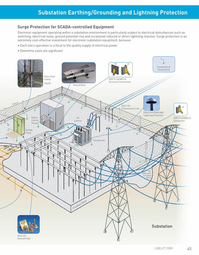
45www.erico.pentair.com 1.800.677.9089
Surge Protection for SCADA-controlled EquipmentElectronic equipment operating within a substation environment is particularly subject to electrical disturbances such as switching, electrical noise, ground potential rise and occasional induced or direct lightning impulse. Surge protection is an extremely cost-effective investment for electronic substation equipment, because:
• Each site’s operation is critical to the quality supply of electrical power
• Downtime costs are significant
Ground Bars
ERICO CADWELD Structure Connections
Fence Post Clamp
FC078
Fence
B162 2Q Ground Plate
Connection to Ground Grid
Transformer
HV Control
SCADA Panel
Station Control House
18” (450 mm) Crushed Rock
EHV / HV Transmission Line
VS
ERICO CADWELD Connection
Crushed Rock
Substation
VB VS
ERICO SYSTEM 3000 Lightning Protection
Substation Earthing/Grounding and Lightning Protection

46 www.erico.pentair.com
ERICO offers a wide range of products for the solar market. In addition to an extensive product offering, ERICO engineers and designers can provide design assistance for many solar installation aspects of your facilities worldwide.
The megawatts of solar energy produced continues to increase globally. More countries have focused resources on this valuable endeavor. Solar photovoltaic power systems include modules, inverters, rack mounting components, monitoring systems for off-grid systems, batteries and charge controllers. Solar power systems are designed to be in service for periods of 30 years or more, therefore it is imperative to construct the systems with products that are designed to help provide efficient operation for the lifetime of the installation. ERICO is uniquely positioned to provide the necessary products, components and services for solar programs worldwide.
Years of experience in the fields of grounding and bonding, lightning protection, low-voltage power distribution, fastening and support and reinforced concrete construction, combined with global manufacturing capabilities, allow ERICO to provide comprehensive solutions for the solar market. Four of our product lines have joined together to offer a full range of solutions: ERICO facility electrical protection products, ERIFLEX low-voltage power distribution products, LENTON concrete reinforcement products and CADDY fixings, fasteners and supports.
ERICO’s products are technically superior, meet or exceed international and industry code requirements and help prolong service life. As a global organization, ERICO is experienced with regional codes, standards and practices, including OEM specs.
Grounding, Lightning Protection, Electrical Connection and Cable Management Solutions for the Solar Power Industry
LENTON TERMINATOR
A
Grounding Accessories
A
ERICO Lightning Protection Systems
A
RIGD and SK Series Strut Clamps
A
Bolt Couplers
A
Copper-bonded Ground Rods
A
Equipotential Ground Mesh
A
SCH Series Strut Clamps
A
Intersystem Bonding Termination (IBTB)
A
Solar Bonding Lugs
A
CADDY PYRAMID
A
ERICO CADWELD Exothermically Welded Connections
A
Ground Enhancement Material
A
MBJ Grounding Braids
A
A PV Array
Solar Products

47www.erico.pentair.com 1.800.677.9089
TDX AC Surge Protection Devices
C
Grounding Bars
C
Cabling Sleeves
C
Two and Four Pole Distribution Blocks
C
C Inverter
ERIFLEX FLEXIBAR
B C
DIN Rail Profiles
B C
Low Voltage Insulators
B C
ERIFLEX FLEXIBAR Supports
B C
Power Blocks/Splice Blocks
B C
Equipment Grounding Bus Bars
B C
Power Terminals
B C
Distribution Blocks
B CB C
TDS50 DC Surge Protection Devices
Terminal Strip
B
Splice Blocks
B
Distribution Blocks
B
B Combiner Box
Insulated Braided Shunt
A B C
Solar Products

www.erico.pentair.com48
Foundation Grounding and Construction, Bonding, Power Connections, Surge Protection, and Lightning Protection
ERICO offers a complete range of foundation grounding and construction, bonding, power connections, surge protection, and lightning protection products for the wind energy industry. In addition to our extensive product offering, our engineers and designers are ready to provide design assistance for your facilities worldwide.
Power Blocks
ERICO Multi-Point Lightning Protection Assemblies
ERICO Cable to Rebar Connections
Cable to Rebar Cable to Cable Cable to Ground Rod
ERICO CADWELD Connections
ERIFLEX Grounding Braids and Bonding Jumpers
Ground Enhancement Material (GEM)
LENTON TERMINATOR Rebar End Anchors
LENTON Bolt Couplers
LENTON LOCK Mechanical Rebar Splicing System
ERICO Power and Control Surge Protection
Lightning Event Counter and Remote Relay
LENTON Standard Couplers and Position Couplers
ERIFLEX FLEXIBARLow Voltage Insulators
Wind Products
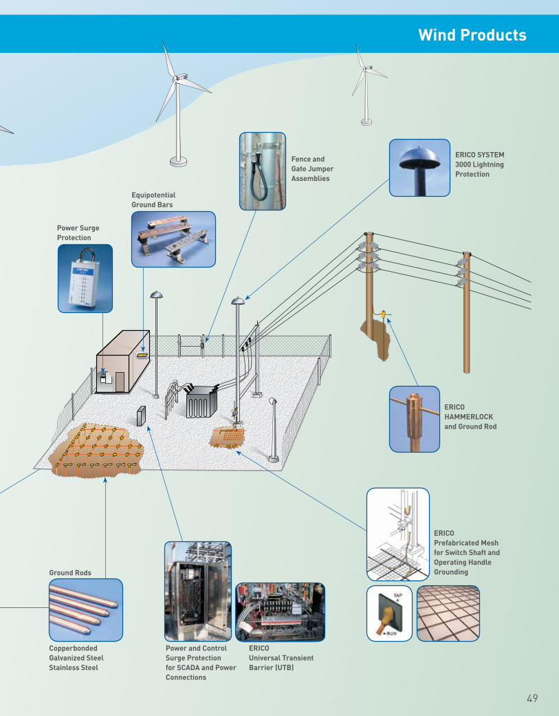
www.erico.pentair.com 1.800.831.7133 49
Equipotential Ground Bars
ERICO SYSTEM 3000 Lightning Protection
Ground Rods
Copperbonded Galvanized Steel Stainless Steel
Power and Control Surge Protection for SCADA and Power Connections
ERICO Universal Transient Barrier (UTB)
Power Surge Protection
Fence and Gate Jumper Assemblies
ERICO HAMMERLOCK and Ground Rod
ERICO Prefabricated Mesh for Switch Shaft and Operating Handle Grounding
Wind Products
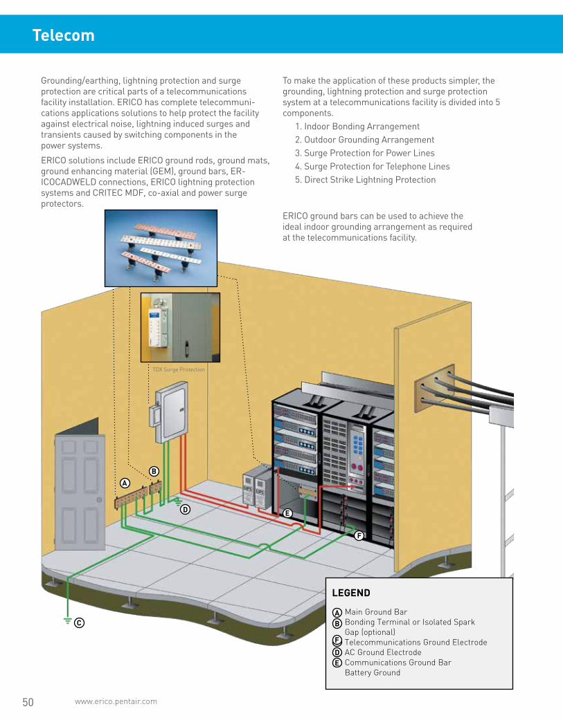
50 www.erico.pentair.com
Main Ground BarBonding Terminal or Isolated Spark Gap (optional) Telecommunications Ground ElectrodeAC Ground Electrode Communications Ground BarBattery Ground
Grounding/earthing, lightning protection and surge protection are critical parts of a telecommunications facility installation. ERICO has complete telecommuni-cations applications solutions to help protect the facility against electrical noise, lightning induced surges and transients caused by switching components in the power systems.
ERICO solutions include ERICO ground rods, ground mats, ground enhancing material (GEM), ground bars, ER-ICOCADWELD connections, ERICO lightning protection systems and CRITEC MDF, co-axial and power surge protectors.
To make the application of these products simpler, the grounding, lightning protection and surge protection system at a telecommunications facility is divided into 5 components.
1. Indoor Bonding Arrangement2. Outdoor Grounding Arrangement3. Surge Protection for Power Lines4. Surge Protection for Telephone Lines5. Direct Strike Lightning Protection
A
AB
CDE
F
B
D
C
E
F
TDX Surge Protection
Telecom
ERICO ground bars can be used to achieve the ideal indoor grounding arrangement as required at the telecommunications facility.
LEGEND

51www.erico.pentair.com 1.800.677.9089
LEGEND
Telecommunication ground electrode system Vertical ground electrodes Tower ground Coaxial and Waveguide feeders Coaxial surge protectors or ground kit RF Ground Bar
The outdoor arrangement of a grounding system at a telecommunications facility is depicted here. This arrangement is not always possible due to certain constraints at the site. Where the telecommunication equipment is installed in a large multi functional building or several floors above the ground floor this layout may not be possible.
Alternative outdoor ground electrode system needs to be considered on a case by case basis if the suggested layout below is not possible to implement.
ERICO offers a full range of products to form the outdoor grounding system at a telecommunications facility.
ABCDEF
A
B
D
C
E
F
E
Telecom

52 www.erico.pentair.com
OR
OR OR
ERICO® DYNASPHERE
ERICO® ERICORE
ISODC* Conventional Cable Smoothweave
Conventional
Direct lightning strikes to telecommunications towers are a reasonably regular occurrence, more so on mountain tops and in certain parts of the world. The traditional approach to lightning protection on towers is to have a lightning rod on the top of the tower and a dedicated down conductor comprised of bare cable or tape that is installed on the tower to connect the lightning rod to the ground.
A modern method is to use an optimal air terminal design, the ERICO Dynasphere mounted on top of the telecommunications mast on a 3-4 metres long fibreglass reinforced pole, FRP. The FRP provides isolation between the air terminal and the tower and helps ensure that the lightning does not flash over and electrify the mast or the antenna. A special purpose downconductor, called the ERICO ERICORE
is routed in the core of the FRP and connects to the bottom of the ERICO Dynasphere via a high voltage, impulse rated termination. The ERICO ERICORE runs along a leg of the tower away from the routes of feeders, down to the tower grounding system. ERICO ERICORE cable is designed to minimize the voltage between itself and the tower so that the bulk of the lightning energy is contained within the cable, thereby protecting the tower and feeders from conducted lightning currents and having much less reliance on bonding practices which sometimes are overlooked or completed incorrectly.
* ISODC - is an isolated lightning protection cable system based around IEC62305. It is designed to isolate the lightning current from sensitive equipment, eliminating the need for separation distances required with conventional cable. Contact ERICO for further information.
Lightning Protection for Telecommunications Towers
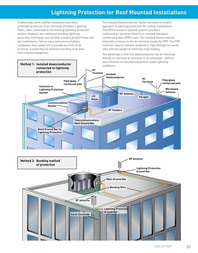
53www.erico.pentair.com 1.800.677.9089
Traditionally, some rooftop installation have been protected by the use of air terminals (Franklin Lightning Rods), often connected to the building lightning protection system. However, the traditional building lightning protection techniques are not well suited to protect these roof top installations. Hence many telecommunications companies have opted not to provide any form of air terminal. Instead they do extensive bonding of all their roof mounted equipment.
Method 1: Isolated downconductor connected to lightning protection
Method 2: Bonding method of protection
The Isolated Downconductor System provides a modern approach to lightning protection for rooftop installations. The ERICO brand of isolated systems provide a traditional air terminal fitted to an isolated fiberglass reinforced plastic (FRP) mast. The isolated downconductor internally connects to the air terminal inside the FRP. The FRP mast has natural isolation properties, high strength for windy sites and low weight to minimize mast loading.
The advantage is that this downconductor can be mounted directly on the mast or structure to be protected – without electrification of mounted equipment under lightning conditions.
Air Terminal
Air Terminal
Isolated Downconductor
Lightning Protection Ground Bar
Connects to Lightning Protection System
Fiberglass reinforced pole
RF Antenna
Fiberglass reinforced pole
Microwave Antenna
Earth Electrode
RF Antenna
Lightning Protection Ground Bar
Bonding Wire
Main Ground Bar
Telecommunications Main Ground Bar
Bond Ground Bar to Lightning Protection
Communications Shelter
Lift Room
RF Feeders
ParapetRF Antenna
Lightning Protection for Roof Mounted Installations

54 www.erico.pentair.com

www.erico.pentair.com
CONNECTORS & POSITIONERS

www.erico.pentair.com 1.800.677.908956
Connectors and PositionersGround Rod Connectors
ERICO HAMMERLOCK Ground Clamp
• Irreversible connection with excellent mechanical strength
• Fast and simple installation requires only a hammer
• No special training required• Low resistance connection• Provides a visual indication of completed
connection• Allows for “T” or pass-through connections
Featured Highlights
The patented ERICO HAMMERLOCK irreversible grounding connector mechanically connects the grounding conductor to the ground rod. Machined from highly conductive copper, the state-of-the-art ERICO HAMMERLOCK provides a low resistance connection designed to withstand ground fault currents and lightning transients. The connector’s mechanically rugged design will help ensure that the highest level of performance is maintained for many years after the connection has been buried in the harsh underground environment.
Ø
Material: Copper Part Number
Ground Rod Diameter, Nominal
Ground Rod Diameter, Actual Conductor Size Number of
Conductors Certifications
Ground Rod Type: Copper-bonded
EHL12FC1K 1/2” 0.50” #6 Solid - #4 Solid, 16 mm² Stranded 1 cULus
EHL12FC1K1K 1/2” 0.50” #6 Solid - #4 Solid, 16 mm² Stranded 2 cULus
EHL12FC1V 1/2” 0.50” #4 Stranded - #2 Stranded, 25 mm² Stranded 1 cULus
EHL12FC2G 1/2” 0.50” 1/0 Stranded - 2/0 Stranded 1 cULus
EHL34C1K 3/4” 0.68” #6 Solid - #4 Solid, 16 mm² Stranded 1 cULus
EHL34C1V 3/4” 0.68” #4 Stranded - #2 Stranded, 25 mm² Stranded 1 cULus
EHL34C2G 3/4” 0.68” 1/0 Stranded - 2/0 Stranded 1 cULus
EHL58C1K 5/8” 0.56” #6 Solid - #4 Solid, 16 mm² Stranded 1 cULus
EHL58C1K1K 5/8” 0.56” #6 Solid - #4 Solid, 16 mm² Stranded 2 cULus
EHL58C1V 5/8” 0.56” #4 Stranded - #2 Stranded, 25 mm² Stranded 1 cULus
EHL58C2G 5/8” 0.56” 1/0 Stranded - 2/0 Stranded 1 cULusGround Rod Type: Galvanized
EHL34G1K 3/4” 0.73” #6 Solid - #4 Solid, 16 mm² Stranded 1 cULus
EHL34G1V 3/4” 0.73” #4 Stranded - #2 Stranded, 25 mm² Stranded 1 cULus
EHL34SG1K 3/4” 0.73” #6 Solid - #4 Solid, 16 mm² Stranded 1
EHL34SG1V 3/4” 0.73” #4 Stranded - #2 Stranded, 25 mm² Stranded 1
EHL58G1K 5/8” 0.63” #6 Solid - #4 Solid, 16 mm² Stranded 1 cULus
EHL58G1K1K 5/8” 0.63” #6 Solid - #4 Solid, 16 mm² Stranded 2 cULus
EHL58G1V 5/8” 0.63” #4 Stranded - #2 Stranded, 25 mm² Stranded 1 cULus
EHL58G2G 5/8” 0.63” 1/0 Stranded - 2/0 Stranded 1 cULus

www.erico.pentair.com 1.800.677.9089 57
Conn
ecto
rs a
nd P
ositi
oner
sGr
ound
Rod
Con
nect
ors
Ground Rod Clamp, Rod to Conductor, Bronze
• For use with copper-bonded ground rods• Parts that are UL Listed are suitable for
direct burial in earth or concrete
Featured Highlights
Ø
TQ
Material: Silicon Bronze Part Number
Ground Rod Diameter, Nominal
Ground Rod Diameter, Actual Conductor Size Wrench Size Certifications
Torque: 150 – 300 in lb
CP34 1/2” – 3/4” 0.50” – 0.68” #10 Solid - 1/0 Stranded, 6 mm² Solid - 50 mm² Stranded 1/2” CSA, cULus
CP38 3/8” 0.38” #10 Solid - #2 Stranded, 6 mm² Solid - 25 mm² Stranded 3/8” cULus
CP58 1/2” – 5/8” 0.50” – 0.56” #10 Solid - #2 Stranded, 6 mm² Solid - 25 mm² Stranded 1/2” CSA, cULus
Torque: 150 – 450 in lb
HDC1 1” 1.00” #8 Solid - 4/0 Stranded, 10 mm² Solid - 95 mm² Stranded 9/16” cULus
HDC12 1/2” 0.50” #10 Solid - #2 Stranded, 6 mm² Solid - 25 mm² Stranded 1/2” CSA, cULus
HDC34 3/4” 0.68” #8 Solid - 1/0 Stranded, 10 mm² Solid - 50 mm² Stranded 9/16” CSA, cULus
HDC34SP 3/4” 0.68” #8 Solid - 3/0 Stranded, 10 mm² Solid - 70 mm² Stranded 9/16” CSA
HDC58 5/8” 0.56” #8 Solid - 1/0 Stranded, 10 mm² Solid - 50 mm² Stranded 9/16” CSA, cULus
HDC58R 5/8” 0.56” #8 Solid - 1/0 Stranded, 10 mm² Solid - 50 mm² Stranded 1/2” CSA, cULus
Ground Rod Clamp, Rod to Conductor, Stainless Steel
• Unique stamped body design will not crack from excessive torque
• Provides a greater surface area contact to allow improved performance of the connector
• Compatible with copper, copper bonded, galvanized, stainless steel, rebar and plain steel ground rods and electrodes
Featured Highlights
Ø
Material: Stainless Steel 304 (EN 1.4301)Torque: 150 – 300 in lb
Part Number
Ground Rod Diameter, Nominal
Ground Rod Diameter, Actual Conductor Size Wrench Size
SP58 1/2” – 5/8” 0.500” – 0.625” #10 Solid - #2 Stranded, 6 mm² Solid - 25 mm² Stranded 1/2”
SP58B916 1/2” – 5/8” 0.500” – 0.625” #10 Solid - #2 Stranded, 6 mm² Solid - 25 mm² Stranded 9/16”

www.erico.pentair.com58
Connectors and PositionersGround Rod Connectors
Ground Rod Clamp, U-Bolt, Tinned, One Conductor
• Tinned finish provides a theft-deterrent appearance
• Accepts conductors in both parallel and perpendicular orientations
Featured Highlights
Ø Ø
Material: Bronze, Stainless Steel 304 (EN 1.4301)Finish: Tinned
Part Number Ground Rod Diameter, Nominal Conductor Size, UL
GC064 5/8” – 3/4” #4 Sol - 2/0 Str, 16 mm² Str - 50 mm² StrGC065 5/8” – 3/4” 2/0 Sol - 250 kcmil Str, 70 mm² Str - 120 mm² Str
Conductor Orientation (Parallel or Perpendicular)
GC064 Conductor Size
Nominal Ground Rod Diameter #4 Sol #4 Str #2 Sol #2 Str 1/0 Sol 1/0 Str-3/0 Sol
5/8” copper-bonded ground rod
Par. Par. Par. Par. Both Perp.
5/8” galvanized/stainless steel ground rod
Par. Par. Par. - Perp. Perp.
3/4” copper-bonded ground rod
Par. - - - Perp. Perp.
3/4” galvanized/stainless steel ground rod
- - - - Perp. -
GC065 Conductor Size
Nominal Ground Rod Diameter
#4 Sol-#4 Str #2 Sol-4/0 Sol 4/0 Str 250 kcmil Str
5/8” copper-bonded ground rod
Par. Both Both Par.
5/8” galvanized/stainless steel ground rod
Par. Both Both Par.
3/4” copper-bonded ground rod
Par. Both Both -
3/4” galvanized/stainless steel ground rod
Par. Both - -

www.erico.pentair.com 1.800.677.9089 59
Conn
ecto
rs a
nd P
ositi
oner
sGr
ound
Rod
Con
nect
ors
Ground Rod Clamp, U-Bolt, Three Conductors
• Ground rod clamp that allows up to three separate conductors to be connected to a ground rod
• Bronze material is a copper alloy with high copper content
• Tinned bronze has theft-deterrent appearance
Featured Highlights
Material: BronzeFinish: Tinned
Part Number
Ground Rod Diameter, Nominal
Ground Rod Diameter, Actual Conductor Size
GC065TH 5/8” – 3/4” 0.625” – 0.750” 2/0 Solid - 250 kcmil Stranded, 70 mm² Stranded - 120 mm² Stranded
Ground Rod Clamp, U-Bolt Saddle, One Conductor
• Clamp that allows a conductor to be connected to a ground rod
Featured Highlights
Material: Copper Alloy Part Number
Ground Rod Diameter, Nominal
Ground Rod Diameter, Actual Conductor Size
REP16120L 3/4” 0.68” #4 Solid - 4/0 Stranded, 16 mm² Stranded - 120 mm² Stranded
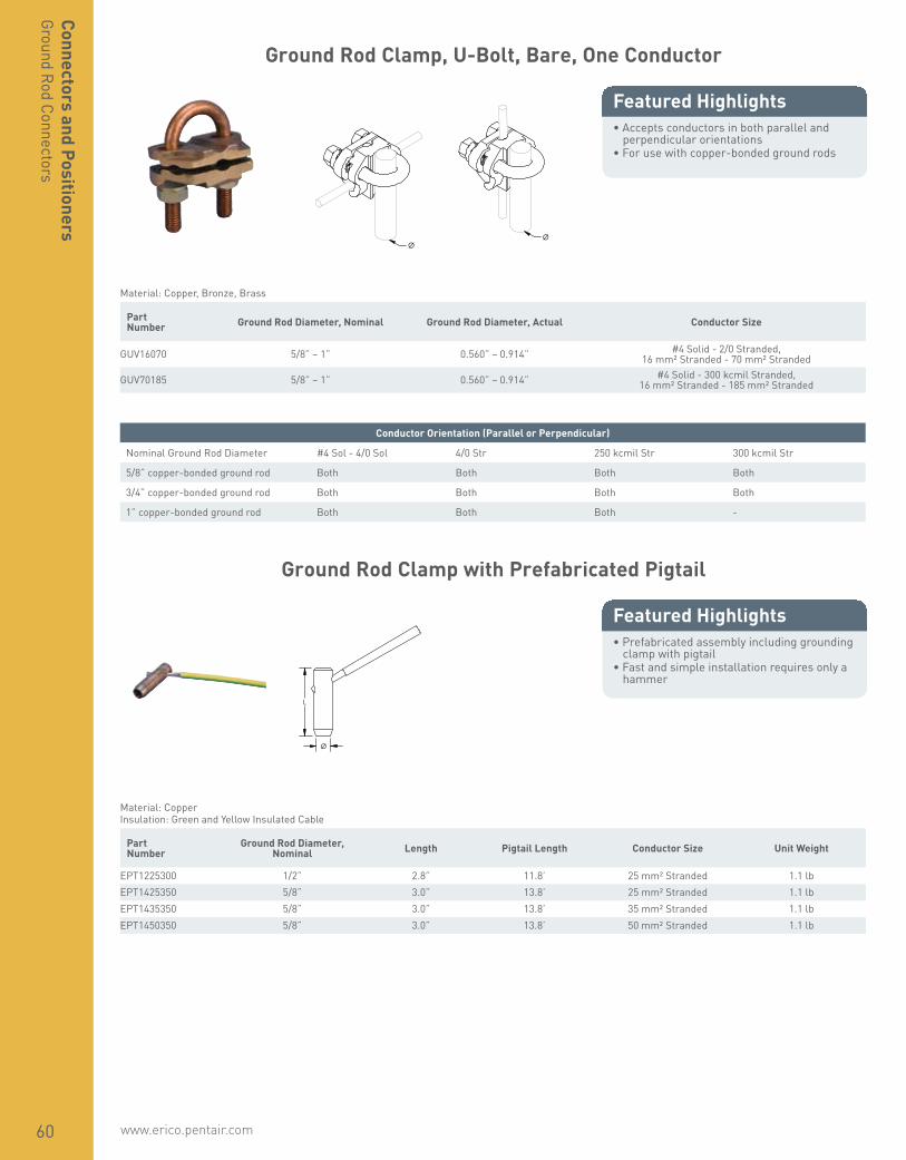
www.erico.pentair.com60
Connectors and PositionersGround Rod Connectors
Ground Rod Clamp, U-Bolt, Bare, One Conductor
• Accepts conductors in both parallel and perpendicular orientations
• For use with copper-bonded ground rods
Featured Highlights
Ø Ø
Material: Copper, Bronze, Brass Part Number Ground Rod Diameter, Nominal Ground Rod Diameter, Actual Conductor Size
GUV16070 5/8” – 1” 0.560” – 0.914” #4 Solid - 2/0 Stranded, 16 mm² Stranded - 70 mm² Stranded
GUV70185 5/8” – 1” 0.560” – 0.914” #4 Solid - 300 kcmil Stranded, 16 mm² Stranded - 185 mm² Stranded
Ground Rod Clamp with Prefabricated Pigtail
• Prefabricated assembly including grounding clamp with pigtail
• Fast and simple installation requires only a hammer
Featured Highlights
L
Ø
Material: CopperInsulation: Green and Yellow Insulated Cable
Part Number
Ground Rod Diameter, Nominal Length Pigtail Length Conductor Size Unit Weight
EPT1225300 1/2” 2.8” 11.8’ 25 mm² Stranded 1.1 lbEPT1425350 5/8” 3.0” 13.8’ 25 mm² Stranded 1.1 lbEPT1435350 5/8” 3.0” 13.8’ 35 mm² Stranded 1.1 lbEPT1450350 5/8” 3.0” 13.8’ 50 mm² Stranded 1.1 lb
Conductor Orientation (Parallel or Perpendicular)
Nominal Ground Rod Diameter #4 Sol - 4/0 Sol 4/0 Str 250 kcmil Str 300 kcmil Str
5/8” copper-bonded ground rod Both Both Both Both
3/4” copper-bonded ground rod Both Both Both Both
1” copper-bonded ground rod Both Both Both -

www.erico.pentair.com 1.800.677.9089 61
Conn
ecto
rs a
nd P
ositi
oner
sGr
ound
Rod
Con
nect
ors
Ground Rod Split Clamp, Rod to Tape
• Used to connect a ground rod to a lug or to tape with a punched hole
Featured Highlights
Ø
TS
Material: Gunmetal Part Number Ground Rod Diameter, Actual Thread Size
RCC16 0.56” Max M10SRC15 0.58” Max M10
U-Bolt Ground Rod Clamp
• Connects conductors to ground rods• Listed to UL® 96
Featured Highlights
W
Ø
H
D
Material: Brass Part Number Conductor Size, UL Ground Rod Diameter,
NominalGround Rod Diameter,
Actual Depth Height Width Unit Weight
LPC795 Class 1 - Class 2 (4/0 Max) 1/2” – 3/4” 0.504” – 0.681” 1.66” 2 1/2” 2” 0.242 lb

www.erico.pentair.com62
Connectors and PositionersGround Rod Connectors
Ground Rod Clamp
• Unique stamped body design will not crack as mechanical forces are increased
• Stainless steel threads will not strip if over-tightened
• Unique internal profile offers pull-out load in excess of four times the UL® 96 requirement
• Listed to UL® 96
Featured Highlights
H
W
Ø
L
Material: Copper Part Number Conductor Size, UL Ground Rod Diameter,
NominalGround Rod Diameter,
Actual Height Length Width Unit Weight
LPC790 Class 1 - Class 2 (4/0 Max) 1/2” – 3/4” 0.504” – 0.681” 1.65” 1 3/4” 0.94” 0.336 lb
Compression Coupler for Copper-Bonded Ground Rod, Pointed
• Threadless compression coupler for use with pointed copper-bonded ground rods
• Inside of coupler is tapered so ground rod compresses during installation to form an irreversible conductive connection
Featured Highlights
L
Ø
Material: Silicon Bronze Part Number
Ground Rod Diameter, Nominal Length Unit Weight Complies With
CC12F 1/2” 2 3/4” 0.29 lbCC34 3/4” 2 3/4” 0.44 lb IEC® EN 62561-2CC58 5/8” 2 3/4” 0.32 lb IEC® EN 62561-2
IEC® EN 62561-2 supercedes EN 50164-2.

www.erico.pentair.com 1.800.677.9089 63
Conn
ecto
rs a
nd P
ositi
oner
sGr
ound
Rod
Con
nect
ors
Compression Coupler for Galvanized Ground Rod, Pointed
• Threadless compression coupler for use with galvanized steel ground rods
• Inside of coupler is tapered so ground rod compresses during installation to form an irreversible conductive connection
Featured Highlights
L
Ø
Material: SteelFinish: Electrogalvanized
Part Number
Ground Rod Diameter, Nominal Length Unit Weight
GCC34 3/4” 3 1/2” 0.36 lbGCC58F 5/8” 3” 0.31 lb
Compression Coupler for Stainless Steel Ground Rod, Pointed
• Threadless compression coupler for use with pointed stainless steel ground rods in corrosive soils
• Inside of coupler is tapered so ground rod compresses during installation to form an irreversible conductive connection
Featured Highlights
L
Ø
Material: Stainless Steel 304 (EN 1.4301) Part Number
Ground Rod Diameter, Nominal Length Unit Weight Certifications
CC34SS 3/4” 3 1/4” 0.34 lb cULusCC58SS 5/8” 3” 0.25 lb cULusCCSS14 14 mm 2 3/4” 0.10 lb

www.erico.pentair.com64
Connectors and PositionersGround Rod Connectors
Threaded Coupler for Copper-Bonded Ground Rod, Sectional
• High-strength couplings are threaded and chamfered at both ends for easy driving
• Corrosion-resistant couplings ensure permanent, low resistance copper-to-copper connections
Featured Highlights
L
Ø
Part Number
Ground Rod Diameter, Nominal Length Thread Size Unit Weight Certifications
Material: BronzeCR12S 9/16” 2.5” 9/16 UNC 0.16 lb CSA, cULusCR34 3/4” 3.0” 3/4 UNC 0.34 lb CSA, cULusCR58 5/8” 2.4” 5/8 UNC 0.23 lb CSA, cULus
Material: Silicon BronzeCR100 1” 3.9” 1 UNC 0.78 lb cULus
Threaded Coupler for Stainless Steel Ground Rod, Sectional
• Corrosion-resistant couplings ensure permanent, low-resistance connections between ground rods
Featured Highlights
L
Ø
Material: Stainless Steel 304 (EN 1.4301) Part Number
Ground Rod Diameter, Nominal Length Thread Size Unit Weight Certifications
CR34SS 3/4” 3.06” 3/4 UNC 0.40 lb cULusCR58CE 5/8” 2.75” 5/8 UNC 0.26 lbCR58SS 5/8” 3.06” 5/8 UNC 0.27 lb cULus

www.erico.pentair.com 1.800.677.9089 65
Grounding Busbar Connector, Solid Round Conductor
• Used to connect ERICO CU-BOND Round Conductor to grounding busbars
Featured Highlights
H
HS
TS
Ø
Material: Copper Alloy, Stainless Steel 18-8 (EN 1.4305)Finish: Tinned
Part Number Height Diameter Hole Size Thread Size ERICO CU-BOND
Conductor Complies With
BCR8T 1.56” 0.79” 0.37” M10 CBSC8 IEC® 62561-1
IEC compliance is valid only for ERICO CU-BOND Conductors listed.
Stamped Bonding Plate
• Stamped bonding plate suitable for structural steel applications
• Listed to UL® 96
Featured Highlights
D
HS2
HS1
W
H
Conductor Size, UL: Class 1 - Class 2 (4/0 Max) Part Number Contact Area Depth Height Width Hole Size 1 Hole Size 2 Unit Weight
Material: Copper — Finish: BareLPC540 8 in² Min 2 1/8” 1 1/4” 4 1/4” 0.2” 0.311” 0.560 lb
Material: Copper — Finish: TinnedLPC540L 8 in² Min 2 1/8” 1 1/4” 4 1/4” 0.2” 0.311” 0.560 lb
Material: Copper, Aluminum, Stainless Steel 304 (EN 1.4301) — Finish: BareLPC540A 8 in² Min 2 1/8” 1 1/4” 4 1/4” 0.2” 0.311” 0.230 lb
Stainless steel separator included with LPC540A for bi-metallic applications. Co
nnec
tors
and
Pos
ition
ers
Grou
nd R
od C
onne
ctor
s

www.erico.pentair.com66
Connectors and PositionersStructural Connectors
Bonding Plate
• Cast bonding plate for structural steel applications
• Listed to UL® 96
Featured Highlights
D
W
HS
H
Conductor Size, UL: Class 1 - Class 2 (4/0 Max) Part Number Contact Area Depth Height Width Hole Size Unit Weight
Material: BrassLPC532 8 in² Min 2 7/8” 0.66” 2 7/8” 5/16” 0.640 lb
Material: Brass — Finish: TinnedLPC532L 8 in² Min 2 7/8” 0.66” 2 7/8” 5/16” 0.640 lb
Cast Beam Bonding Clamp
• Clamp for bonding cable to flat metal objects such as I-beams, angle irons and channel irons
• Listed to UL® 96
Featured Highlights
FT
W
D
Conductor Size, UL: Class 1 - Class 2 (4/0 Max) Part Number Flange Thickness Depth Width Unit Weight
Material: Copper — Finish: BareLPC559 1/4” Max 2 1/4” 1.6” 0.385 lb
Material: Copper — Finish: TinnedLPC559L 1/4” Max 2 1/4” 1.6” 0.385 lb

www.erico.pentair.com 1.800.677.9089 67
Conn
ecto
rs a
nd P
ositi
oner
sSt
ruct
ural
Con
nect
ors
Cast Two Bolt Beam Bonding Clamp
• Clamp for bonding cable to flat metal objects such as I-beams, angle irons and channel irons
• Listed to UL® 96
Featured Highlights D
FT
W
H
Conductor Size, UL: Class 1 - Class 2 (4/0 Max) Part Number Flange Thickness Depth Height Width Contact Area Unit Weight
Material: CopperLPC557 1” Max 2 3/4” 2” 4” 8 in² Min 2.055 lb
Material: Copper — Finish: TinnedLPC557L 1” Max 2 3/4” 2” 4” 8 in² Min 2.055 lb
Beam Clamp for Solid Round Conductor
• Clamp for attaching solid round conductor such as ERICO CU-BOND Round Conductor to flat metal objects such as I-beams, angle irons and channel irons
• For use with copper-bonded, copper, or stainless steel solid conductors
Featured Highlights
H
D W FT
Material: Stainless Steel 316 (EN 1.4401) Part Number Width Height Depth Flange
ThicknessERICO CU-BOND
Conductor Unit Weight Complies With
SBCS0810 2.17” 3.35” 2.76” 1/4” – 1” CBSC8, CBSC10 0.61 lb IEC® 62561-4SBCS1314 2.17” 3.54” 2.76” 1/4” – 1” CBSC13, CBSC14 0.61 lb IEC® 62561-4
IEC compliance is valid only for ERICO CU-BOND Conductors listed.

www.erico.pentair.com68
Connectors and PositionersStructural Connectors
Prefabricated Lug Bond
• Made with bare annealed copper cable• Tinned copper NEMA® lugs welded to the
cable with ERICO CADWELD connections
Featured Highlights
Prefabricated lug bonds are custom made to specifications. Common usage includes cable tray bonding and grounding, structure bonds, surge arrester leads and power jumpers.
Material: CopperFinish: Tinned
Part Number Conductor Size Number
of Wires Length 1 Length 2 Width Thickness Hole Size Angle
Lug Configuration: B212B2121L8 #4 Stranded 7 8” 1.47” 1” 0.19” 9/16” -B2121V12 #2 Stranded 7 12” 1.47” 1” 0.19” 9/16” -B2122G16 2/0 Stranded 7 16” 1.47” 1” 0.19” 9/16” -B2122Q00318 4/0 Stranded 7 318” 1.47” 1” 0.19” 9/16” -B2122Q20 4/0 Stranded 7 20” 1.47” 1” 0.19” 9/16” -B2122Q24 4/0 Stranded 7 24” 1.47” 1” 0.19” 9/16” -
Lug Configuration: B213B2131L15 #4 Stranded 7 15” 3.25” 1” 0.19” 9/16” -B2131L20 #4 Stranded 7 20” 3.25” 1” 0.19” 9/16” -B2131L22 #4 Stranded 7 22” 3.25” 1” 0.19” 9/16” -B2131L24 #4 Stranded 7 24” 3.25” 1” 0.19” 9/16” -B2131L28 #4 Stranded 7 28” 3.25” 1” 0.19” 9/16” -B2131L32 #4 Stranded 7 32” 3.25” 1” 0.19” 9/16” -B2131L35 #4 Stranded 7 35” 3.25” 1” 0.19” 9/16” -B2131L38 #4 Stranded 7 38” 3.25” 1” 0.19” 9/16” -B2131L42 #4 Stranded 7 42” 3.25” 1” 0.19” 9/16” -B2131L44 #4 Stranded 7 44” 3.25” 1” 0.19” 9/16” -B2131V18 #2 Stranded 7 18” 3.25” 1” 0.19” 9/16” -B2131V36 #2 Stranded 7 36” 3.25” 1” 0.19” 9/16” -B2132G11 2/0 Stranded 7 11” 3.25” 1” 0.19” 9/16” -B2132G14 2/0 Stranded 7 14” 3.25” 1” 0.19” 9/16” -B2132Q18 4/0 Stranded 7 18” 3.25” 1” 0.19” 9/16” -B2132Q36 4/0 Stranded 7 36” 3.25” 1” 0.19” 9/16” -
B21-2-1L-12
B21 Lug Bond Assembly
2 Lug Configuration 2 = Double-Lug Bond, 1-Hole each on Straight Lugs3 = Double-Lug Bond, 2-Holes each on Straight Lugs6 = Single-Lug Bond Stub, 1-Hole on Straight Lug7 = Single-Lug Bond Stub, 2-Holes on Straight Lug8 = Single-Lug Bond Stub, 1-Hole on 45º Lug9 = Single-Lug Bond Stub, 2-Holes on 45º Lug
1L Cable Code 1L = #4 Stranded1V = #2 Stranded2C = 1/0 Stranded2G = 2/0 Stranded2Q = 4/0 Stranded2Q = 4/0 Stranded2V = 250 MCM Stranded
12 Bond Length in inches (from outer-most hole center)
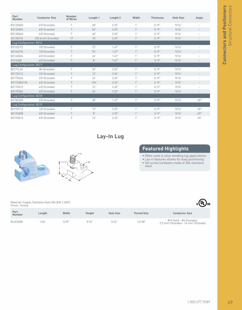
www.erico.pentair.com 1.800.677.9089 69
Conn
ecto
rs a
nd P
ositi
oner
sSt
ruct
ural
Con
nect
ors
Part Number Conductor Size Number
of Wires Length 1 Length 2 Width Thickness Hole Size Angle
B2132Q48 4/0 Stranded 7 48” 3.25” 1” 0.19” 9/16” -B2132Q54 4/0 Stranded 7 54” 3.25” 1” 0.19” 9/16” -B2132Q60 4/0 Stranded 7 60” 3.25” 1” 0.19” 9/16” -B2132V18 250 kcmil Stranded 19 18” 3.25” 1” 0.19” 9/16” -
Lug Configuration: B216B2162C72 1/0 Stranded 7 72” 1.47” 1” 0.19” 9/16” -B2162C96 1/0 Stranded 7 96” 1.47” 1” 0.19” 9/16” -B2162Q24 4/0 Stranded 7 24” 1.47” 1” 0.19” 9/16” -B2162Q8 4/0 Stranded 7 8” 1.47” 1” 0.19” 9/16” -
Lug Configuration: B217B2171L24 #4 Stranded 7 24” 3.25” 1” 0.19” 9/16” -B2172C12 1/0 Stranded 7 12” 3.25” 1” 0.19” 9/16” -B2172G24 2/0 Stranded 7 24” 3.25” 1” 0.19” 9/16” -B2172Q00196 4/0 Stranded 7 196” 3.25” 1” 0.19” 9/16” -B2172Q12 4/0 Stranded 7 12” 3.25” 1” 0.19” 9/16” -B2172Q24 4/0 Stranded 7 24” 3.25” 1” 0.19” 9/16” -
Lug Configuration: B218B2182Q30 4/0 Stranded 7 30” 1.47” 1” 0.19” 9/16” 45°
Lug Configuration: B219B2192C12 1/0 Stranded 7 12” 3.25” 1” 0.19” 9/16” 45°B2192Q08 4/0 Stranded 7 8” 3.25” 1” 0.19” 9/16” 45°B2192Q12 4/0 Stranded 7 12” 3.25” 1” 0.19” 9/16” 45°
Lay-In Lug
• Often used in solar bonding lug applications• Lay-in features allows for easy positioning• Set screw hardware made of 304 stainless
steel
Featured Highlights
H
W L
TS
HS
Material: Copper, Stainless Steel 304 (EN 1.4301)Finish: Tinned
Part Number Length Width Height Hole Size Thread Size Conductor Size
EL6CADB 1.04” 0.39” 0.76” 0.22” 1/4 NF #14 Solid - #4 Stranded, 2.5 mm² Stranded - 16 mm² Stranded

www.erico.pentair.com70
Connectors and PositionersStructural Connectors
Solar Bonding Lug
• Bonds the frames and mounting structures of solar photo voltaic systems in accordance with NEC® requirements
• Copper alloy is corrosion resistant and galvanically compatible with copper grounding conductors and aluminum photovoltaic module frames
• Lay-in feature allows for easy positioning along multiple frames
Featured Highlights TS
HS
Material: Bronze, Stainless Steel 18-8 (EN 1.4305)Finish: Tinned
Part Number Direct Burial Conductor Size Hole Size Screw Included Thread Size
EL6CS No #14 Solid - #6 Stranded 0.221” Yes 10 UNSEL6CS8 No #14 Solid - #6 Stranded 0.221” Yes 8 UNSEL6CSDB Yes #14 Solid - #6 Stranded 0.221” Yes 10 UNSEL6CSDB8 Yes #14 Solid - #6 Stranded 0.221” Yes 8 UNSEL6CSDBNH Yes #14 Solid - #6 Stranded 0.221” NoEL6CSNH No #14 Solid - #6 Stranded 0.221” No
Transformer Tank Grounding Connector with Rotating Eye Bolt
• Rotating eye bolt accommodates cable either vertically or horizontally
• Fits all EEI®-NEMA® distribution transformers
• No special tools required; use regular lineman’s wrench
Featured Highlights
TS
Material: Bronze, Stainless Steel 302 (EN 1.4324), Stainless Steel 304 (EN 1.4301) Part Number Conductor Size Thread Size
TGC2/0 #10 Solid - 2/0 Stranded 1/2 UNC

www.erico.pentair.com 1.800.677.9089 71
Conn
ecto
rs a
nd P
ositi
oner
sSt
ruct
ural
Con
nect
ors
Transformer Tank Grounding Connector, External Thread
• Fits all EEI®-NEMA® distribution transformers
• No special tools required; use regular lineman’s wrench
Featured Highlights
TS
Material: Bronze Part Number Conductor Size Thread Size
Finish: TinnedCC207 #6 Solid - 1/0 Stranded 1/2 UNC
Transformer Tank Grounding Connector, Internal Thread
• Fits all EEI®-NEMA® distribution transformers
• No special tools required; use regular lineman’s wrench
Featured Highlights
TS
Material: Bronze, Stainless Steel 304 (EN 1.4301) Part Number Conductor Size Thread Size
VC207IT #6 Solid - 1/0 Stranded 3/8 UNC

www.erico.pentair.com72
Connectors and PositionersConductor to Conductor Connectors
Earth Boss
• Provides preferential equipotential bonding connection point
Featured Highlights
L
TS
Ø
Material: Stainless Steel 316 (EN 1.4401), Steel Part Number Length Diameter Thread Size
50010EBOSS 1.97” 1.97” M10
The surface of the earth boss needs to be cleaned before welding. Welding procedures vary, depending on the type of steel used.
516 Parallel Cable Connector
• Cable splice with positive single bolt tension grip on cable or wire
• For use with all full size cables on Class I/II structures
• Listed to UL® 96
Featured Highlights W
D
Conductor Size, UL: Class 1 - Class 2 (4/0 Max) Part Number Depth Width Unit Weight
Material: Copper — Finish: BareLPC516 1.84” 1 1/2” 0.40 lb
Material: Copper — Finish: TinnedLPC516L 1.84” 1 1/2” 0.40 lb
Material: Copper, Aluminum, Stainless Steel 18-8 (EN 1.4305) — Finish: BareLPC516A 1.84” 1 1/2” 0.26 lb
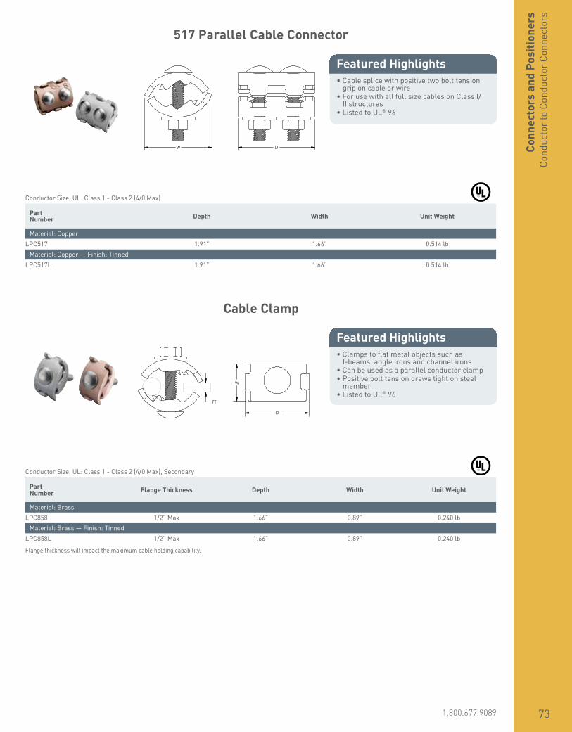
www.erico.pentair.com 1.800.677.9089 73
Conn
ecto
rs a
nd P
ositi
oner
sCo
nduc
tor t
o Co
nduc
tor C
onne
ctor
s
517 Parallel Cable Connector
• Cable splice with positive two bolt tension grip on cable or wire
• For use with all full size cables on Class I/II structures
• Listed to UL® 96
Featured Highlights
W D
Conductor Size, UL: Class 1 - Class 2 (4/0 Max) Part Number Depth Width Unit Weight
Material: CopperLPC517 1.91” 1.66” 0.514 lb
Material: Copper — Finish: TinnedLPC517L 1.91” 1.66” 0.514 lb
Cable Clamp
• Clamps to flat metal objects such as I-beams, angle irons and channel irons
• Can be used as a parallel conductor clamp• Positive bolt tension draws tight on steel
member• Listed to UL® 96
Featured Highlights
FT
W
D
Conductor Size, UL: Class 1 - Class 2 (4/0 Max), Secondary Part Number Flange Thickness Depth Width Unit Weight
Material: BrassLPC858 1/2” Max 1.66” 0.89” 0.240 lb
Material: Brass — Finish: TinnedLPC858L 1/2” Max 1.66” 0.89” 0.240 lb
Flange thickness will impact the maximum cable holding capability.

www.erico.pentair.com74
Connectors and PositionersConductor to Conductor Connectors
Stamped Bolted Parallel Cable Connector
• For positive bolt tension cable clamping• Listed to UL® 96
Featured Highlights
W
H D
Conductor Size, UL: Class 1 - Class 2 (4/0 Max) Part Number Depth Height Width Unit Weight
Material: CopperLPC502 1 1/2” 1 1/2” 1.78” 0.215 lb
Material: Copper — Finish: TinnedLPC502L 1 1/2” 1 1/2” 1.78” 0.215 lb
Material: Copper, Aluminum, Stainless Steel 304 (EN 1.4301)LPC502A 1 1/2” 1 1/2” 1.78” 0.194 lb
Stainless steel separator included with LPC502A for bi-metallic applications.
Jumper Clamp for Telecom
• For use in telecom applications
Featured Highlights
TS
W
Material: BronzeFinish: Tinned
Part Number Width Thread Size Conductor Size
KUL 1.4” 5/16 UNC #6 Solid
Although a #6 Solid conductor is similar in size to a metric 16 mm² Solid conductor, the UL listing is currently only for #6 Solid.
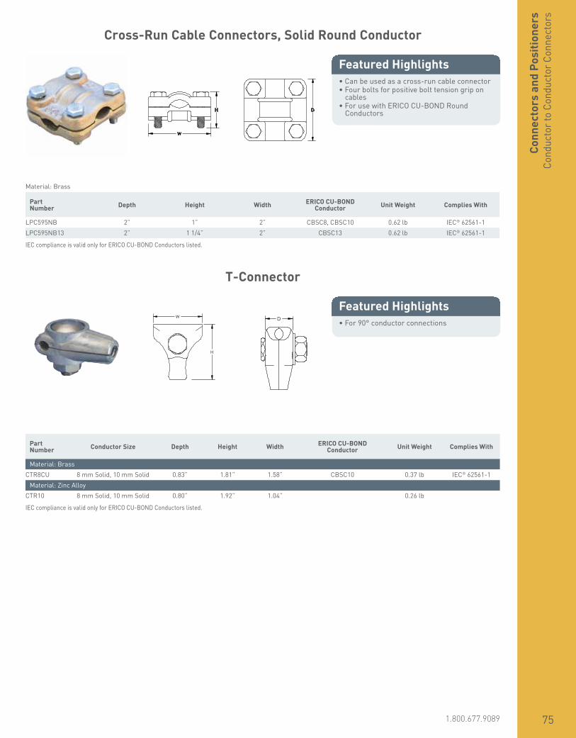
www.erico.pentair.com 1.800.677.9089 75
Conn
ecto
rs a
nd P
ositi
oner
sCo
nduc
tor t
o Co
nduc
tor C
onne
ctor
s
Cross-Run Cable Connectors, Solid Round Conductor
• Can be used as a cross-run cable connector• Four bolts for positive bolt tension grip on
cables• For use with ERICO CU-BOND Round
Conductors
Featured Highlights
W
H D
Material: Brass Part Number Depth Height Width ERICO CU-BOND
Conductor Unit Weight Complies With
LPC595NB 2” 1” 2” CBSC8, CBSC10 0.62 lb IEC® 62561-1LPC595NB13 2” 1 1/4” 2” CBSC13 0.62 lb IEC® 62561-1
IEC compliance is valid only for ERICO CU-BOND Conductors listed.
T-Connector
• For 90° conductor connections
Featured Highlights
H
W D
Part Number Conductor Size Depth Height Width ERICO CU-BOND
Conductor Unit Weight Complies With
Material: BrassCTR8CU 8 mm Solid, 10 mm Solid 0.83” 1.81” 1.58” CBSC10 0.37 lb IEC® 62561-1
Material: Zinc AlloyCTR10 8 mm Solid, 10 mm Solid 0.80” 1.92” 1.04” 0.26 lb
IEC compliance is valid only for ERICO CU-BOND Conductors listed.
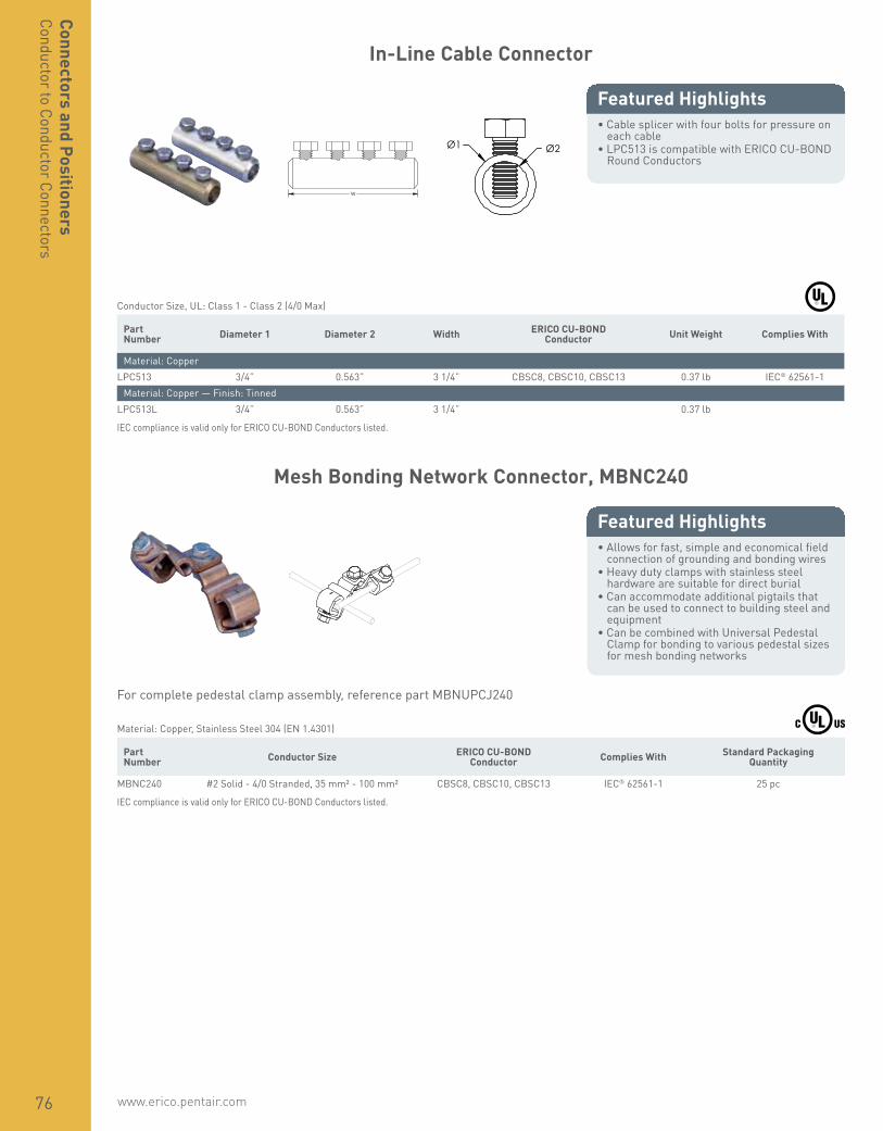
www.erico.pentair.com76
Connectors and PositionersConductor to Conductor Connectors
In-Line Cable Connector
• Cable splicer with four bolts for pressure on each cable
• LPC513 is compatible with ERICO CU-BOND Round Conductors
Featured Highlights
W
Ø1 Ø2
Conductor Size, UL: Class 1 - Class 2 (4/0 Max) Part Number Diameter 1 Diameter 2 Width ERICO CU-BOND
Conductor Unit Weight Complies With
Material: CopperLPC513 3/4” 0.563” 3 1/4” CBSC8, CBSC10, CBSC13 0.37 lb IEC® 62561-1
Material: Copper — Finish: TinnedLPC513L 3/4” 0.563” 3 1/4” 0.37 lb
IEC compliance is valid only for ERICO CU-BOND Conductors listed.
Mesh Bonding Network Connector, MBNC240
• Allows for fast, simple and economical field connection of grounding and bonding wires
• Heavy duty clamps with stainless steel hardware are suitable for direct burial
• Can accommodate additional pigtails that can be used to connect to building steel and equipment
• Can be combined with Universal Pedestal Clamp for bonding to various pedestal sizes for mesh bonding networks
Featured Highlights
For complete pedestal clamp assembly, reference part MBNUPCJ240
Material: Copper, Stainless Steel 304 (EN 1.4301) Part Number Conductor Size ERICO CU-BOND
Conductor Complies With Standard Packaging Quantity
MBNC240 #2 Solid - 4/0 Stranded, 35 mm² - 100 mm² CBSC8, CBSC10, CBSC13 IEC® 62561-1 25 pc
IEC compliance is valid only for ERICO CU-BOND Conductors listed.

www.erico.pentair.com 1.800.677.9089 77
Conn
ecto
rs a
nd P
ositi
oner
sCo
nduc
tor t
o Co
nduc
tor C
onne
ctor
s
Mesh Bonding Network Connector, MBNC240A
• Allows for fast, simple and economical field connection of grounding and bonding wires
• Heavy duty clamps with stainless steel hardware are suitable for direct burial
• Can be combined with Universal Pedestal Clamp for bonding to various pedestal sizes for mesh bonding networks
Featured Highlights
For complete pedestal clamp assembly, reference part number MBNUPCJ240
Material: Copper, Stainless Steel 304 (EN 1.4301) Part Number Conductor Size Standard Packaging Quantity
MBNC240A #2 Solid - 4/0 Stranded, 35 mm² - 100 mm² 25 pc
Mesh Bonding Network Connector, MBNC82
• Allows for fast, simple and economical field connection of grounding and bonding wires
• Heavy duty clamps with stainless steel hardware are suitable for direct burial
• Can accommodate additional pigtails that can be used to connect to building steel and equipment
• Can be combined with Universal Pedestal Clamp for bonding to various pedestal sizes for mesh bonding networks
Featured Highlights
For complete pedestal clamp assembly, reference part number MBNUPJ82
Material: Bronze, Stainless Steel 304 (EN 1.4301) Part Number Conductor Size Standard Packaging Quantity
MBNC82 #8 Solid - #2 Stranded, 10 mm² Solid - 35 mm² Stranded 25 pc

www.erico.pentair.com78
Connectors and PositionersConductor to Conductor Connectors
SRG Connector
• Allows for fast, simple and economical field connection of grounding and bonding wires
• Heavy duty clamps with stainless steel hardware are suitable for direct burial
• Can accommodate additional pigtails that can be used to connect to building steel and equipment
• Can be combined with Universal Pedestal Clamp for bonding to various pedestal sizes for mesh bonding networks
Featured Highlights
Material: Bronze, Stainless Steel 304 (EN 1.4301) Part Number Conductor Size
SRGC46 #6 Solid - #4 Stranded, 16 mm² Stranded
Split Bolt Connector
• Unplated high-strength silicon bronze accommodates copper to copper connections
• Tin plated, high-strength copper alloy split bolt with spacer separates dissimilar conductors and accommodates copper-to-copper, copper-to-aluminum and aluminum-to-aluminum connections
Featured Highlights
Material: Silicon Bronze Part Number Conductor Size Certifications
Tin Plating: NoESB2 #6 Solid - #2 Stranded, 16 mm² Stranded - 25 mm² Stranded cULusESB2/0 #2 Solid - 2/0 Stranded, 35 mm² Stranded - 50 mm² Stranded ULESB4 #8 Solid - #4 Solid, 10 mm² Stranded - 16 mm² Stranded cULusESB4/0 1/0 Solid - 250 kcmil Stranded, 70 mm² Stranded - 120 mm² StrandedESB6 #10 Solid - #6 Stranded, 6 mm² Stranded - 10 mm² Stranded cULusESB8 #16 Stranded - #8 Stranded, 1.5 mm² Stranded - 6 mm² Stranded cULus
Tin Plating: YesESBP1/0 #6 Solid - 1/0 Stranded, 16 mm² Stranded - 50 mm² Stranded ULESBP2 #8 Solid - #2 Stranded, 10 mm² Stranded - 25 mm² Stranded ULESBP2/0 #8 Solid - 2/0 Stranded, 10 mm² Stranded - 50 mm² Stranded ULESBP350 3/0 Stranded - 350 kcmil Stranded, 95 mm² Stranded - 150 mm² StrandedESBP4 #8 Solid - #3 Stranded, 10 mm² Stranded - 25 mm² Stranded ULESBP4/0 #4 Stranded - 250 kcmil Stranded, 25 mm² Stranded - 120 mm² StrandedESBP6 #10 Stranded - #6 Stranded, 6 mm² Stranded - 10 mm² Stranded ULESBP8 #14 Stranded - #8 Stranded, 2.5 mm² Stranded - 6 mm² Stranded UL
Oxide inhibitor recommmended when used on aluminum conductor.

www.erico.pentair.com 1.800.677.9089 79
Conn
ecto
rs a
nd P
ositi
oner
sCo
nduc
tor t
o Co
nduc
tor C
onne
ctor
s
Vise Clamp
• Used to splice two conductors together
Featured Highlights
Material: Bronze Part Number Conductor Size
VC62 #6 Solid - #2 Solid, 16 mm² Solid - 25 mm² Solid
Vise Clamp for Telecom
• Used to bond messenger wire to ground tap conductors
• When clamp is tightened, the piercing teeth puncture the insulation on the messenger wire, forming a positive ground connection without stripping the cable
Featured Highlights
H
D
Material: Copper Alloy, Stainless Steel 304 (EN 1.4301)Finish: Tinned
Part Number Height Width Depth Diameter Thread Size Unit Weight
EVC167P 1 5/8” 1 1/4” 1” 0.146” – 0.312” 5/16 UNC 0.21 lb
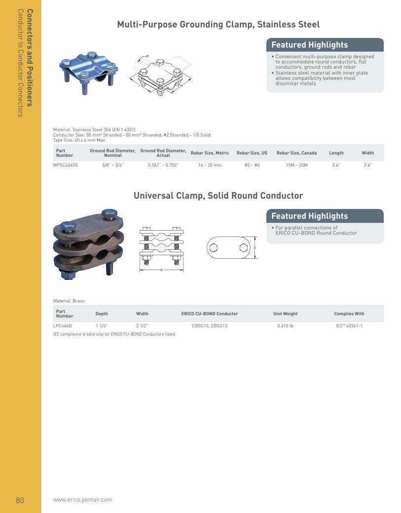
www.erico.pentair.com80
Connectors and PositionersConductor to Conductor Connectors
Multi-Purpose Grounding Clamp, Stainless Steel
• Convenient multi-purpose clamp designed to accommodate round conductors, flat conductors, ground rods and rebar
• Stainless steel material with inner plate allows compatibility between most dissimilar metals
Featured HighlightsØ
L W
Material: Stainless Steel 304 (EN 1.4301)Conductor Size: 35 mm² Stranded - 50 mm² Stranded, #2 Stranded - 1/0 SolidTape Size: 40 x 4 mm Max
Part Number
Ground Rod Diameter, Nominal
Ground Rod Diameter, Actual Rebar Size, Metric Rebar Size, US Rebar Size, Canada Length Width
MPSC404SS 5/8” – 3/4” 0.561” – 0.750” 16 – 20 mm #5 – #6 15M – 20M 2.6” 2.6”
Universal Clamp, Solid Round Conductor
• For parallel connections of ERICO CU-BOND Round Conductor
Featured Highlights
W
D
Material: Brass Part Number Depth Width ERICO CU-BOND Conductor Unit Weight Complies With
LPC466B 1 1/4” 2 1/2” CBSC10, CBSC13 0.615 lb IEC® 62561-1
IEC compliance is valid only for ERICO CU-BOND Conductors listed.

www.erico.pentair.com 1.800.677.9089 81
Conn
ecto
rs a
nd P
ositi
oner
sPi
pe, F
ence
and
Gat
e Co
nnec
tors
Water Pipe Ground Clamp
• High-strength silicone bronze• Used for connecting copper conductors to
metallic water pipe or ground rods
Featured Highlights
ø
Part Number Pipe Size, Nominal Conductor Size Certifications
Material: Silicon BronzeCWP1JJ 1/2” – 1” #10 Solid - #4 Stranded, 6 mm² Stranded - 16 mm² StrandedCWP1JU 1/2” – 1” #10 Solid - #2 Stranded, 6 mm² Stranded - 25 mm² Stranded CSA, cULusCWP2JU 1 1/4” – 2” #10 Solid - #2 Stranded, 6 mm² Stranded - 25 mm² Stranded CSA, cULusCWP4J 2 1/2” – 4” #10 Solid - #4 Stranded, 6 mm² Stranded - 16 mm² Stranded CSA, cULusCWP6J 4 1/2” – 6” #10 Solid - #4 Stranded, 6 mm² Stranded - 16 mm² Stranded CSA
Material: Zinc AlloyZWP1J 1/2” – 1” #10 Solid - #6 Solid, 6 mm² Stranded - 10 mm² Stranded cULus
Optional copper screw for use in direct burial applications.
Water/Gas Pipe Ground Clamp
• High-strength silicone bronze• Used for connecting copper conductors to
metallic water pipe, ground rods, or flexible gas pipe (CSST) with brass hex fittings
• Conform to the requirements of the 2009 edition of NFPA® 54, NFGC® (National Fuel Gas Code) and NEC® (National Electric Code) for bonding corrugated stainless steel tubing (CSST) gas piping systems to the grounding conductor of the building’s electrical system
• SH version for outdoor applications
Featured Highlights
W
Material: Silicon Bronze Part Number Pipe Size, Nominal Hex Width Conductor Size Certifications
For Outdoor Use: NoCWP1J 1/2” – 1” 1” – 1 1/4” #10 Solid - #2 Solid, 6 mm² Solid - 25 mm² Stranded CSA, cULusCWP2J 1 1/4” – 2” 1 1/2” – 2 1/8” #10 Solid - #2 Stranded, 6 mm² Stranded - 25 mm² Stranded CSA, cULusCWP3J 2 1/2” – 4” 2 1/2” – 3 1/8” #10 Solid - #4 Stranded, 6 mm² Stranded - 16 mm² Stranded cULus
For Outdoor Use: YesCWP1JSH 1/2” – 1” 1” – 1 1/4” #10 Solid - #2 Stranded, 6 mm² Stranded - 25 mm² Stranded cULusCWP2JSH 1 1/4” – 2” 1 1/2” – 2 1/8” #10 Solid - #2 Stranded, 6 mm² Solid - 25 mm² Stranded cULusCWP3JSH 2 1/2” – 4” 2 1/2” – 3 1/8” #10 Solid - #4 Stranded, 6 mm² Stranded - 16 mm² Stranded cULus

www.erico.pentair.com82
Connectors and PositionersPipe, Fence and Gate Connectors
Cast Pipe Clamp
• Clamp for bonding horizontal or vertical pipes to the lightning protection system
• Listed to UL® 96
Featured Highlights
W
OD
D
Conductor Size, UL: Class 1 - Class 2 (4/0 Max), Secondary Part Number Outer Diameter Depth Width Unit Weight
Material: Brass — Finish: BareLPC580 0.75” – 1.32” 1 1/2” 2 3/4” 0.59 lb
Material: Brass — Finish: TinnedLPC580L 0.75” – 1.32” 1 1/2” 2 3/4” 0.59 lb
Cast U-Bolt Pipe Clamp
• Clamp for bonding conductor to handrails, pipes and rebar to lightning protection system
• Listed to UL® 96
Featured Highlights
W
H
OD
D
Conductor Size, UL: Class 1 - Class 2 (4/0 Max), Secondary Part Number Outer Diameter Depth Height Width Unit Weight
Material: Brass — Finish: BareLPC570 0.68” – 1.50” 1.8” 3” 2.67” 0.715 lb
Material: Brass — Finish: TinnedLPC570L 0.68” – 1.50” 1.8” 3” 2.67” 0.715 lb

www.erico.pentair.com 1.800.677.9089 83
Conn
ecto
rs a
nd P
ositi
oner
sPi
pe, F
ence
and
Gat
e Co
nnec
tors
Notched Cast U-Bolt Pipe Clamp
• Clamp for bonding of handrails and pipes to the lightning protection system
• Notched hole makes assembly easy and eliminates loose hardware
• Listed to UL® 96
Featured Highlights
W
H OD
D
Conductor Size, UL: Class 1 - Class 2 (4/0 Max) Part Number Outer Diameter Depth Height Width Unit Weight
Material: Aluminum — Finish: BareLPA571 2” – 2 1/2” 1.96” 3 1/2” 3.63” 0.400 lb
Material: Brass — Finish: BareLPC571 2” – 2 1/2” 1.96” 3 1/2” 3.63” 0.835 lb
Material: Brass — Finish: TinnedLPC571L 2” – 2 1/2” 1.96” 3 1/2” 3.63” 0.835 lb
Pipe to Rigid Conduit Ground Clamp
• For use in grounding rigid conduit systems to metallic water pipe
Featured Highlights
Material: Bronze Part Number Water Pipe Size Rigid Conduit Size Conductor Size
CWP1JH12 1/2” – 1” 1/2” #10 Solid - #6 SolidCWP1JH34 1/2” – 1” 3/4” #10 Solid - 2/0 StrandedCWP2JH34 1 1/4” – 2” 3/4” #10 Solid - 2/0 StrandedCWP2JH44 1 1/4” – 2” 1” #10 Solid - 3/0 StrandedCWP4JH34 2 1/2” – 4” 3/4” #10 Solid - 2/0 Stranded

www.erico.pentair.com84
Connectors and PositionersPipe, Fence and Gate Connectors
Stamped U-Bolt Pipe Clamp
• Clamp for bonding of pipes and exhaust stacks to the lightning protection system
• Listed to UL® 96
Featured Highlights
H
W
OD
D
Part Number Outer Diameter Depth Height Width Unit Weight
Material: Copper, Stainless Steel 304 (EN 1.4301)LPC5964 3.900” – 4.625” 2” 5 13/16” 6.250” 0.885 lbLPC5966 0.438” – 6.858” 2” 8 13/16” 8.313” 0.820 lb
Stamped U-Bolt Pipe Clamp, 90°
• Clamp for bonding of pipes, handrails and exhaust stacks to the lightning protection system
• Listed to UL® 96
Featured Highlights
W
H OD
D
Conductor Size, UL: Class 1 - Class 2 (4/0 Max) Part Number Outer Diameter Depth Height Width Unit Weight
Material: Copper, Stainless Steel 304 (EN 1.4301)LPC5962 1.900” – 2.625” 2” 3.625” 4.675” 0.515 lbLPC5963 2.630” – 3.630” 2” 4.693” 5.500” 0.763 lb
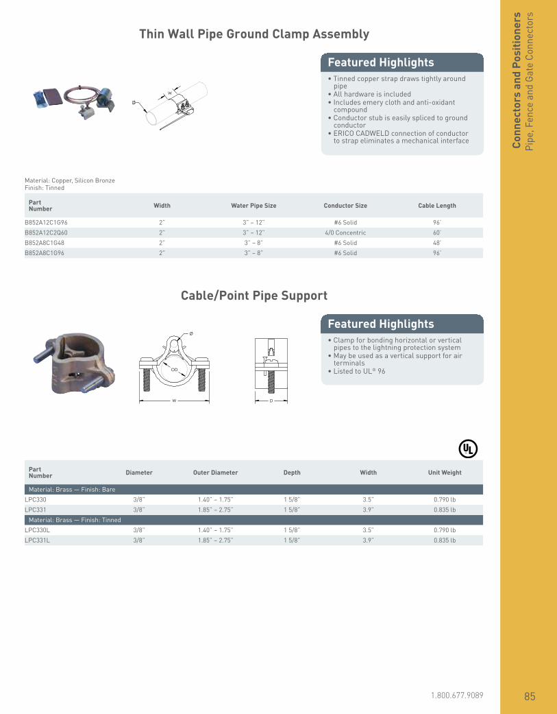
www.erico.pentair.com 1.800.677.9089 85
Conn
ecto
rs a
nd P
ositi
oner
sPi
pe, F
ence
and
Gat
e Co
nnec
tors
Thin Wall Pipe Ground Clamp Assembly
• Tinned copper strap draws tightly around pipe
• All hardware is included• Includes emery cloth and anti-oxidant
compound• Conductor stub is easily spliced to ground
conductor• ERICO CADWELD connection of conductor
to strap eliminates a mechanical interface
Featured Highlights
W
Material: Copper, Silicon BronzeFinish: Tinned
Part Number Width Water Pipe Size Conductor Size Cable Length
B852A12C1G96 2” 3” – 12” #6 Solid 96’B852A12C2Q60 2” 3” – 12” 4/0 Concentric 60’B852A8C1G48 2” 3” – 8” #6 Solid 48’B852A8C1G96 2” 3” – 8” #6 Solid 96’
Cable/Point Pipe Support
• Clamp for bonding horizontal or vertical pipes to the lightning protection system
• May be used as a vertical support for air terminals
• Listed to UL® 96
Featured Highlights
W
OD
Ø
D
Part Number Diameter Outer Diameter Depth Width Unit Weight
Material: Brass — Finish: BareLPC330 3/8” 1.40” – 1.75” 1 5/8” 3.5” 0.790 lbLPC331 3/8” 1.85” – 2.75” 1 5/8” 3.9” 0.835 lb
Material: Brass — Finish: TinnedLPC330L 3/8” 1.40” – 1.75” 1 5/8” 3.5” 0.790 lbLPC331L 3/8” 1.85” – 2.75” 1 5/8” 3.9” 0.835 lb

www.erico.pentair.com86
Connectors and PositionersPipe, Fence and Gate Connectors
Fence Clamp, One Conductor
• Theft-deterrent appearance• Stainless steel hardware included• Tin plating minimizes the risk of corrosion• The clamp accepts the conductor either in
parallel or at right angles to the pipe
Featured Highlights Ø
Material: Bronze, Stainless Steel 304 (EN 1.4301)Finish: Tinned
Part Number
Fence Post Size, Nominal
Fence Post Outside Diameter, Actual Conductor Size ERICO CU-BOND
Conductor Complies With Certifications
FC073 1 1/2” 1.90” #4 Solid - 2/0 Stranded, 16 mm² Stranded - 70 mm² Stranded
FC074 1 1/2” 1.90” 2/0 Solid - 250 kcmil Stranded, 50 mm² Stranded - 120 mm² Stranded
FC075 2” 2.38” #4 Solid - 2/0 Stranded, 16 mm² Stranded - 70 mm² Stranded CBSC8 IEC® 62561-1 cULus
FC076 2” 2.38” 2/0 Solid - 250 kcmil Stranded, 50 mm² Stranded - 120 mm² Stranded CBSC10, CBSC13 IEC® 62561-1
FC078 2 1/2” 2.88” 2/0 Solid - 250 kcmil Stranded, 16 mm² Stranded - 120 mm² Stranded
FC079 3” 3.50” #4 Solid - 2/0 Stranded, 16 mm² Stranded - 70 mm² Stranded
FC080 3” 3.50” 2/0 Solid - 250 kcmil Stranded, 50 mm² Stranded - 120 mm² Stranded
FC082 3 1/2” 4.00” #4 Solid - 2/0 Stranded, 16 mm² Stranded - 120 mm² Stranded
IEC compliance is valid only for ERICO CU-BOND Conductors listed.
Fence Clamp, Two Conductors
• Theft-deterrent appearance• Stainless steel hardware included• Tin plating minimizes the risk of corrosion
Featured Highlights Ø
Material: Copper Alloy, Stainless Steel 304 (EN 1.4301)Finish: Tinned
Part Number
Fence Post Size, Nominal
Fence Post Outside Diameter, Actual Conductor Size
FC076DH 2” 2.38” 2/0 Solid - 250 kcmil Stranded, 50 mm² Stranded - 120 mm² StrandedFC078DH 2 1/2” 2.88” 2/0 Solid - 250 kcmil Stranded, 16 mm² Stranded - 120 mm² StrandedFC082DH 3 1/2” 4.00” #4 Solid - 2/0 Stranded, 16 mm² Stranded - 120 mm² Stranded

www.erico.pentair.com 1.800.677.9089 87
Conn
ecto
rs a
nd P
ositi
oner
sPi
pe, F
ence
and
Gat
e Co
nnec
tors
Fence Clamp for Field-Welded Connections
• Ideal for when ERICO CADWELD connections cannot be made to aluminum pipe or thin-wall steel tube
• Stainless steel hardware included• Can be used when field-welding conductors
Featured Highlights Ø
Material: Electrolytic CopperFinish: Tinned
Part Number Fence Post Size, Nominal Fence Post Outside Diameter, Actual
B522B 1 1/4” 1.66”B522C 1 1/2” 1.90”B522D 2” 2.38”B522E 2 1/2” 2.88”B522F 3” 3.50”B522G 3 1/2” 4.00”B522H 4” 4.50”B522K 6” 6.63”
Flexible Jumper for Fence and Gate Grounding
• Used to bond gates, switch operating handles and any other item where movement or vibration requires a flexible grounding jumper
• Multi-stranded insulated ropelay conductor provides flexibility and strand protection
• Swaged ends of jumper allow larger conductor to fit in the same mold as concentric conductor
• Connections are made with ERICO CADWELD exothermic connections using the same mold required for other fence post connections
Featured Highlights
FJ-2Q-24
FJ Flexible Jumper
2Q Cable Code #2 Solid = 1T2/0 Stranded = 2G4/0 Stranded = 2Q
24 Length of Jumper (inches)
Material: Copper, Polyethylene Rubber
Part Number Cable Code Conductor Size Cable Length
FJ1T18 1T #2 Solid 18”FJ1T24 1T #2 Solid 24”FJ1T240 1T #2 Solid 240”FJ1T42 1T #2 Solid 42”FJ1T96 1T #2 Solid 96”
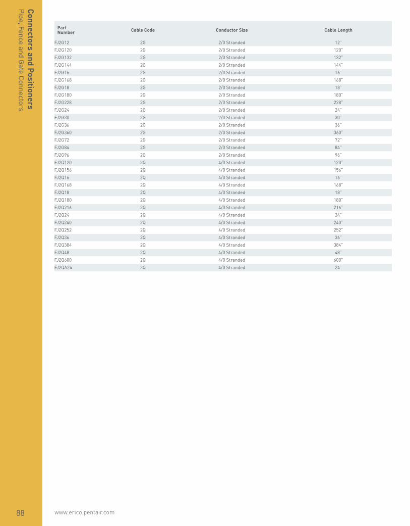
www.erico.pentair.com88
Connectors and PositionersPipe, Fence and Gate Connectors
Part Number Cable Code Conductor Size Cable Length
FJ2G12 2G 2/0 Stranded 12”FJ2G120 2G 2/0 Stranded 120”FJ2G132 2G 2/0 Stranded 132”FJ2G144 2G 2/0 Stranded 144”FJ2G16 2G 2/0 Stranded 16”FJ2G168 2G 2/0 Stranded 168”FJ2G18 2G 2/0 Stranded 18”FJ2G180 2G 2/0 Stranded 180”FJ2G228 2G 2/0 Stranded 228”FJ2G24 2G 2/0 Stranded 24”FJ2G30 2G 2/0 Stranded 30”FJ2G36 2G 2/0 Stranded 36”FJ2G360 2G 2/0 Stranded 360”FJ2G72 2G 2/0 Stranded 72”FJ2G84 2G 2/0 Stranded 84”FJ2G96 2G 2/0 Stranded 96”FJ2Q120 2Q 4/0 Stranded 120”FJ2Q156 2Q 4/0 Stranded 156”FJ2Q16 2Q 4/0 Stranded 16”FJ2Q168 2Q 4/0 Stranded 168”FJ2Q18 2Q 4/0 Stranded 18”FJ2Q180 2Q 4/0 Stranded 180”FJ2Q216 2Q 4/0 Stranded 216”FJ2Q24 2Q 4/0 Stranded 24”FJ2Q240 2Q 4/0 Stranded 240”FJ2Q252 2Q 4/0 Stranded 252”FJ2Q36 2Q 4/0 Stranded 36”FJ2Q384 2Q 4/0 Stranded 384”FJ2Q48 2Q 4/0 Stranded 48”FJ2Q600 2Q 4/0 Stranded 600”FJ2QA24 2Q 4/0 Stranded 24”

www.erico.pentair.com 1.800.677.9089 89
Conn
ecto
rs a
nd P
ositi
oner
sPi
pe, F
ence
and
Gat
e Co
nnec
tors
Prefabricated Fence Clamp Assembly with Single Ground Lead
• Ideal for when ERICO CADWELD connections cannot be made to aluminum pipe or thin-wall steel tube
• Stainless steel hardware included• Available in either left or right-hand
orientation
Featured Highlights Ø
A235-D-2G-2-RH
A235 Series
D Nominal Pipe Size (inches) B = 1 1/4”C = 1 1/2”D = 2”E = 2 1/2”F = 3”G = 3-1/2”H = 4”
2G Ground Lead Cable Code (AWG) 2C = 1/0 Stranded2G = 2/0 Stranded2Q = 4/0 Stranded
2 Ground Lead Length (feet)
RH Ground Lead Side LH = Left HandRH = Right Hand
Material: Copper, Stainless Steel 18-8 (EN 1.4305), Stainless Steel 304 (EN 1.4301)Finish: Tinned
Part Number
Fence Post Size, Nominal
Fence Post Outside Diameter, Actual
Ground Lead Conductor Size
Ground Lead Length
Orientation: Left HandA235C2C1LH 1 1/2” 1.90” 1/0 Str 1’A235D2G4LH 2” 2.38” 2/0 Str 4’A235D2Q4LH 2” 2.38” 4/0 Str 4’A235D2Q5LH 2” 2.38” 4/0 Str 5’A235E2G4LH 2 1/2” 2.88” 2/0 Str 4’A235E2Q4LH 2 1/2” 2.88” 4/0 Str 4’A235E2Q5LH 2 1/2” 2.88” 4/0 Str 5’A235F2C2LH 3” 3.50” 1/0 Str 2’
Orientation: Right HandA235D2G2RH 2” 2.38” 2/0 Str 2’A235D2Q4RH 2” 2.38” 4/0 Str 4’A235D2Q5RH 2” 2.38” 4/0 Str 5’A235E2Q2RH 2 1/2” 2.88” 4/0 Str 2’A235E2Q5RH 2 1/2” 2.88” 4/0 Str 5’A235G2Q2RH 3 1/2” 4.00” 4/0 Str 2’A235H2C10RH 4” 4.50” 1/0 Str 10’
Right hand orientation shown in diagram.
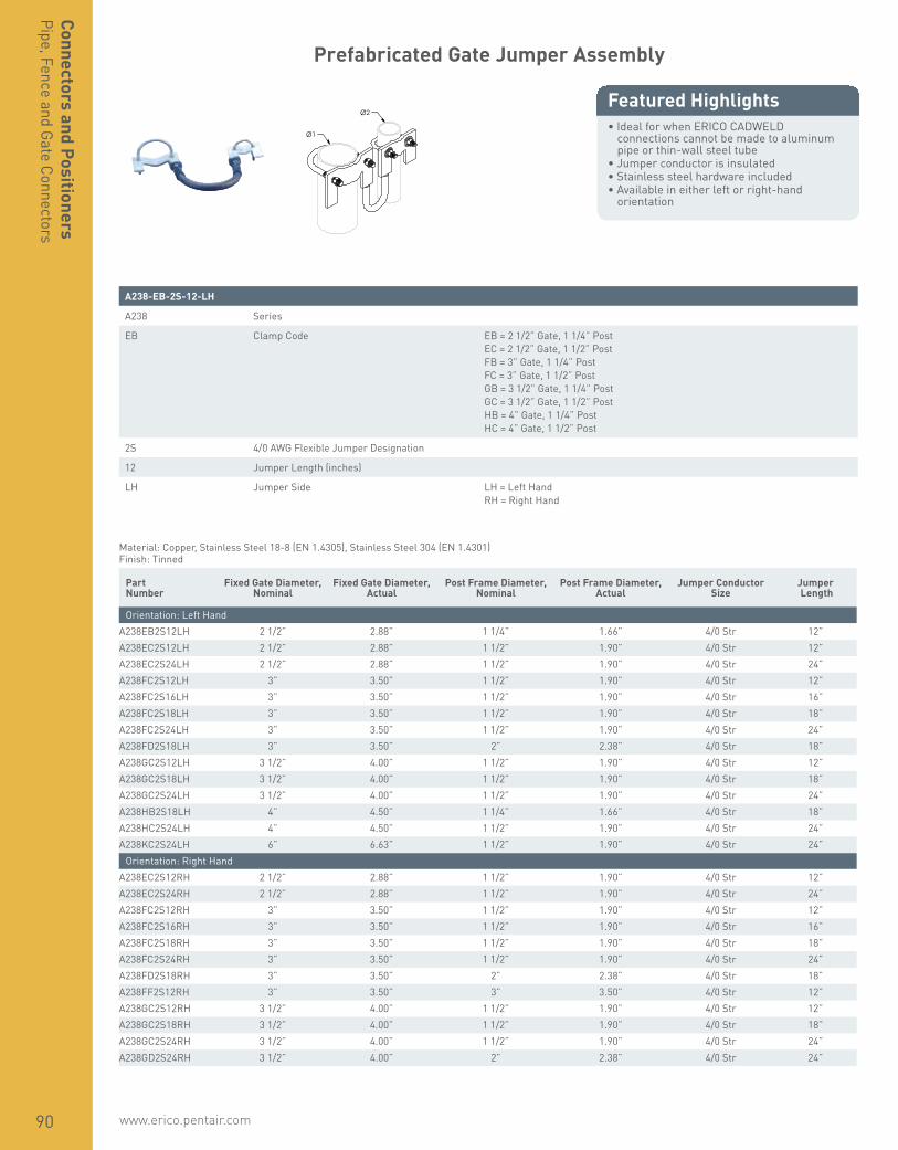
www.erico.pentair.com90
Connectors and PositionersPipe, Fence and Gate Connectors
Prefabricated Gate Jumper Assembly
• Ideal for when ERICO CADWELD connections cannot be made to aluminum pipe or thin-wall steel tube
• Jumper conductor is insulated• Stainless steel hardware included• Available in either left or right-hand
orientation
Featured Highlights Ø2
Ø1
A238-EB-2S-12-LH
A238 Series
EB Clamp Code EB = 2 1/2” Gate, 1 1/4” PostEC = 2 1/2” Gate, 1 1/2” PostFB = 3” Gate, 1 1/4” PostFC = 3” Gate, 1 1/2” PostGB = 3 1/2” Gate, 1 1/4” PostGC = 3 1/2” Gate, 1 1/2” PostHB = 4” Gate, 1 1/4” PostHC = 4” Gate, 1 1/2” Post
2S 4/0 AWG Flexible Jumper Designation
12 Jumper Length (inches)
LH Jumper Side LH = Left HandRH = Right Hand
Material: Copper, Stainless Steel 18-8 (EN 1.4305), Stainless Steel 304 (EN 1.4301)Finish: Tinned
Part Number
Fixed Gate Diameter, Nominal
Fixed Gate Diameter, Actual
Post Frame Diameter, Nominal
Post Frame Diameter, Actual
Jumper Conductor Size
Jumper Length
Orientation: Left HandA238EB2S12LH 2 1/2” 2.88” 1 1/4” 1.66” 4/0 Str 12”A238EC2S12LH 2 1/2” 2.88” 1 1/2” 1.90” 4/0 Str 12”A238EC2S24LH 2 1/2” 2.88” 1 1/2” 1.90” 4/0 Str 24”A238FC2S12LH 3” 3.50” 1 1/2” 1.90” 4/0 Str 12”A238FC2S16LH 3” 3.50” 1 1/2” 1.90” 4/0 Str 16”A238FC2S18LH 3” 3.50” 1 1/2” 1.90” 4/0 Str 18”A238FC2S24LH 3” 3.50” 1 1/2” 1.90” 4/0 Str 24”A238FD2S18LH 3” 3.50” 2” 2.38” 4/0 Str 18”A238GC2S12LH 3 1/2” 4.00” 1 1/2” 1.90” 4/0 Str 12”A238GC2S18LH 3 1/2” 4.00” 1 1/2” 1.90” 4/0 Str 18”A238GC2S24LH 3 1/2” 4.00” 1 1/2” 1.90” 4/0 Str 24”A238HB2S18LH 4” 4.50” 1 1/4” 1.66” 4/0 Str 18”A238HC2S24LH 4” 4.50” 1 1/2” 1.90” 4/0 Str 24”A238KC2S24LH 6” 6.63” 1 1/2” 1.90” 4/0 Str 24”
Orientation: Right HandA238EC2S12RH 2 1/2” 2.88” 1 1/2” 1.90” 4/0 Str 12”A238EC2S24RH 2 1/2” 2.88” 1 1/2” 1.90” 4/0 Str 24”A238FC2S12RH 3” 3.50” 1 1/2” 1.90” 4/0 Str 12”A238FC2S16RH 3” 3.50” 1 1/2” 1.90” 4/0 Str 16”A238FC2S18RH 3” 3.50” 1 1/2” 1.90” 4/0 Str 18”A238FC2S24RH 3” 3.50” 1 1/2” 1.90” 4/0 Str 24”A238FD2S18RH 3” 3.50” 2” 2.38” 4/0 Str 18”A238FF2S12RH 3” 3.50” 3” 3.50” 4/0 Str 12”A238GC2S12RH 3 1/2” 4.00” 1 1/2” 1.90” 4/0 Str 12”A238GC2S18RH 3 1/2” 4.00” 1 1/2” 1.90” 4/0 Str 18”A238GC2S24RH 3 1/2” 4.00” 1 1/2” 1.90” 4/0 Str 24”A238GD2S24RH 3 1/2” 4.00” 2” 2.38” 4/0 Str 24”
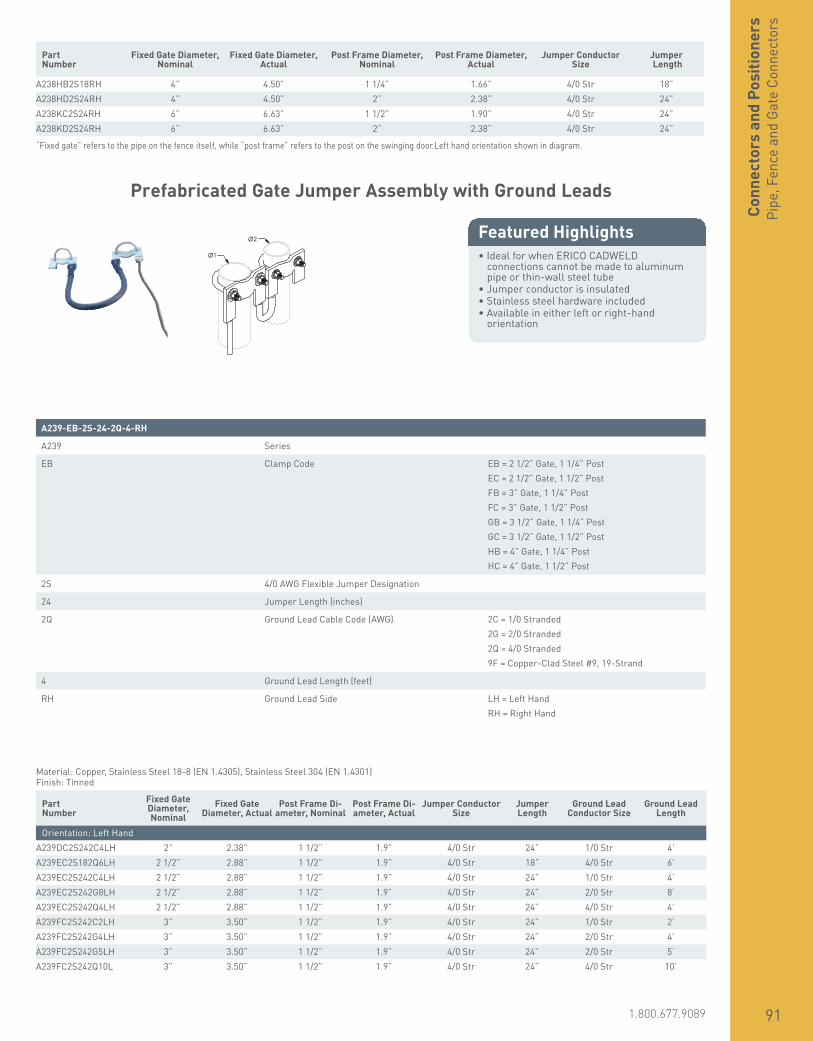
www.erico.pentair.com 1.800.677.9089 91
Conn
ecto
rs a
nd P
ositi
oner
sPi
pe, F
ence
and
Gat
e Co
nnec
tors
Part Number
Fixed Gate Diameter, Nominal
Fixed Gate Diameter, Actual
Post Frame Diameter, Nominal
Post Frame Diameter, Actual
Jumper Conductor Size
Jumper Length
A238HB2S18RH 4” 4.50” 1 1/4” 1.66” 4/0 Str 18”A238HD2S24RH 4” 4.50” 2” 2.38” 4/0 Str 24”A238KC2S24RH 6” 6.63” 1 1/2” 1.90” 4/0 Str 24”A238KD2S24RH 6” 6.63” 2” 2.38” 4/0 Str 24”
“Fixed gate” refers to the pipe on the fence itself, while “post frame” refers to the post on the swinging door.Left hand orientation shown in diagram.
Prefabricated Gate Jumper Assembly with Ground Leads
• Ideal for when ERICO CADWELD connections cannot be made to aluminum pipe or thin-wall steel tube
• Jumper conductor is insulated• Stainless steel hardware included• Available in either left or right-hand
orientation
Featured Highlights
A239-EB-2S-24-2Q-4-RH
A239 Series
EB Clamp Code EB = 2 1/2” Gate, 1 1/4” PostEC = 2 1/2” Gate, 1 1/2” PostFB = 3” Gate, 1 1/4” PostFC = 3” Gate, 1 1/2” PostGB = 3 1/2” Gate, 1 1/4” PostGC = 3 1/2” Gate, 1 1/2” PostHB = 4” Gate, 1 1/4” PostHC = 4” Gate, 1 1/2” Post
2S 4/0 AWG Flexible Jumper Designation
24 Jumper Length (inches)
2Q Ground Lead Cable Code (AWG) 2C = 1/0 Stranded2G = 2/0 Stranded2Q = 4/0 Stranded9F = Copper-Clad Steel #9, 19-Strand
4 Ground Lead Length (feet)
RH Ground Lead Side LH = Left HandRH = Right Hand
Ø2
Ø1
Material: Copper, Stainless Steel 18-8 (EN 1.4305), Stainless Steel 304 (EN 1.4301)Finish: Tinned
Part Number
Fixed Gate Diameter, Nominal
Fixed Gate Diameter, Actual
Post Frame Di-ameter, Nominal
Post Frame Di-ameter, Actual
Jumper Conductor Size
Jumper Length
Ground Lead Conductor Size
Ground Lead Length
Orientation: Left HandA239DC2S242C4LH 2” 2.38” 1 1/2” 1.9” 4/0 Str 24” 1/0 Str 4’A239EC2S182Q6LH 2 1/2” 2.88” 1 1/2” 1.9” 4/0 Str 18” 4/0 Str 6’A239EC2S242C4LH 2 1/2” 2.88” 1 1/2” 1.9” 4/0 Str 24” 1/0 Str 4’A239EC2S242G8LH 2 1/2” 2.88” 1 1/2” 1.9” 4/0 Str 24” 2/0 Str 8’A239EC2S242Q4LH 2 1/2” 2.88” 1 1/2” 1.9” 4/0 Str 24” 4/0 Str 4’A239FC2S242C2LH 3” 3.50” 1 1/2” 1.9” 4/0 Str 24” 1/0 Str 2’A239FC2S242G4LH 3” 3.50” 1 1/2” 1.9” 4/0 Str 24” 2/0 Str 4’A239FC2S242G5LH 3” 3.50” 1 1/2” 1.9” 4/0 Str 24” 2/0 Str 5’A239FC2S242Q10L 3” 3.50” 1 1/2” 1.9” 4/0 Str 24” 4/0 Str 10’
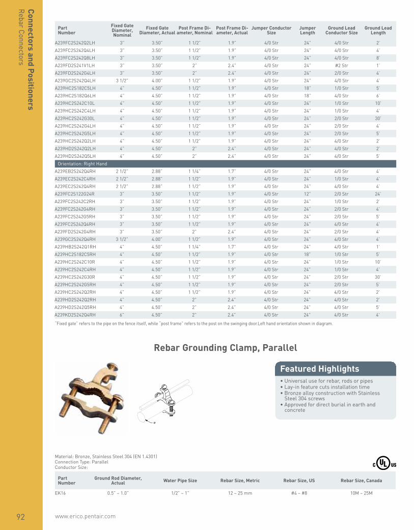
www.erico.pentair.com92
Connectors and PositionersRebar Connectors
Part Number
Fixed Gate Diameter, Nominal
Fixed Gate Diameter, Actual
Post Frame Di-ameter, Nominal
Post Frame Di-ameter, Actual
Jumper Conductor Size
Jumper Length
Ground Lead Conductor Size
Ground Lead Length
A239FC2S242Q2LH 3” 3.50” 1 1/2” 1.9” 4/0 Str 24” 4/0 Str 2’A239FC2S242Q4LH 3” 3.50” 1 1/2” 1.9” 4/0 Str 24” 4/0 Str 4’A239FC2S242Q8LH 3” 3.50” 1 1/2” 1.9” 4/0 Str 24” 4/0 Str 8’A239FD2S241V1LH 3” 3.50” 2” 2.4” 4/0 Str 24” #2 Str 1’A239FD2S242G4LH 3” 3.50” 2” 2.4” 4/0 Str 24” 2/0 Str 4’A239GC2S242Q4LH 3 1/2” 4.00” 1 1/2” 1.9” 4/0 Str 24” 4/0 Str 4’A239HC2S182C5LH 4” 4.50” 1 1/2” 1.9” 4/0 Str 18” 1/0 Str 5’A239HC2S182Q6LH 4” 4.50” 1 1/2” 1.9” 4/0 Str 18” 4/0 Str 6’A239HC2S242C10L 4” 4.50” 1 1/2” 1.9” 4/0 Str 24” 1/0 Str 10’A239HC2S242C4LH 4” 4.50” 1 1/2” 1.9” 4/0 Str 24” 1/0 Str 4’A239HC2S242G30L 4” 4.50” 1 1/2” 1.9” 4/0 Str 24” 2/0 Str 30’A239HC2S242G4LH 4” 4.50” 1 1/2” 1.9” 4/0 Str 24” 2/0 Str 4’A239HC2S242G5LH 4” 4.50” 1 1/2” 1.9” 4/0 Str 24” 2/0 Str 5’A239HC2S242Q2LH 4” 4.50” 1 1/2” 1.9” 4/0 Str 24” 4/0 Str 2’A239HD2S242Q2LH 4” 4.50” 2” 2.4” 4/0 Str 24” 4/0 Str 2’A239HD2S242Q5LH 4” 4.50” 2” 2.4” 4/0 Str 24” 4/0 Str 5’
Orientation: Right HandA239EB2S242Q4RH 2 1/2” 2.88” 1 1/4” 1.7” 4/0 Str 24” 4/0 Str 4’A239EC2S242C4RH 2 1/2” 2.88” 1 1/2” 1.9” 4/0 Str 24” 1/0 Str 4’A239EC2S242Q4RH 2 1/2” 2.88” 1 1/2” 1.9” 4/0 Str 24” 4/0 Str 4’A239FC2S122G24R 3” 3.50” 1 1/2” 1.9” 4/0 Str 12” 2/0 Str 24’A239FC2S242C2RH 3” 3.50” 1 1/2” 1.9” 4/0 Str 24” 1/0 Str 2’A239FC2S242G4RH 3” 3.50” 1 1/2” 1.9” 4/0 Str 24” 2/0 Str 4’A239FC2S242G5RH 3” 3.50” 1 1/2” 1.9” 4/0 Str 24” 2/0 Str 5’A239FC2S242Q4RH 3” 3.50” 1 1/2” 1.9” 4/0 Str 24” 4/0 Str 4’A239FD2S242G4RH 3” 3.50” 2” 2.4” 4/0 Str 24” 2/0 Str 4’A239GC2S242Q4RH 3 1/2” 4.00” 1 1/2” 1.9” 4/0 Str 24” 4/0 Str 4’A239HB2S242Q1RH 4” 4.50” 1 1/4” 1.7” 4/0 Str 24” 4/0 Str 1’A239HC2S182C5RH 4” 4.50” 1 1/2” 1.9” 4/0 Str 18” 1/0 Str 5’A239HC2S242C10R 4” 4.50” 1 1/2” 1.9” 4/0 Str 24” 1/0 Str 10’A239HC2S242C4RH 4” 4.50” 1 1/2” 1.9” 4/0 Str 24” 1/0 Str 4’A239HC2S242G30R 4” 4.50” 1 1/2” 1.9” 4/0 Str 24” 2/0 Str 30’A239HC2S242G5RH 4” 4.50” 1 1/2” 1.9” 4/0 Str 24” 2/0 Str 5’A239HC2S242Q2RH 4” 4.50” 1 1/2” 1.9” 4/0 Str 24” 4/0 Str 2’A239HD2S242Q2RH 4” 4.50” 2” 2.4” 4/0 Str 24” 4/0 Str 2’A239HD2S242Q5RH 4” 4.50” 2” 2.4” 4/0 Str 24” 4/0 Str 5’A239KD2S242Q4RH 6” 4.50” 2” 2.4” 4/0 Str 24” 4/0 Str 4’
“Fixed gate” refers to the pipe on the fence itself, while “post frame” refers to the post on the swinging door.Left hand orientation shown in diagram.
Rebar Grounding Clamp, Parallel
• Universal use for rebar, rods or pipes• Lay-in feature cuts installation time• Bronze alloy construction with Stainless
Steel 304 screws• Approved for direct burial in earth and
concrete
Featured Highlights
ø
Material: Bronze, Stainless Steel 304 (EN 1.4301)Connection Type: ParallelConductor Size:
Part Number
Ground Rod Diameter, Actual Water Pipe Size Rebar Size, Metric Rebar Size, US Rebar Size, Canada
EK16 0.5” – 1.0” 1/2” – 1” 12 – 25 mm #4 – #8 10M – 25M

www.erico.pentair.com 1.800.677.9089 93
Conn
ecto
rs a
nd P
ositi
oner
sRe
bar C
onne
ctor
s
Rebar Grounding Clamp, Perpendicular
• Universal use for rebar, rods or pipes• Lay-in feature cuts installation time• Bronze alloy construction with Stainless
Steel 304 screws• Approved for direct burial in earth and
concrete
Featured Highlights
Material: Bronze, Stainless Steel 304 (EN 1.4301)Connection Type: PerpendicularConductor Size:
Part Number
Ground Rod Diameter, Actual Water Pipe Size Rebar Size, Metric Rebar Size, US Rebar Size, Canada
EK17 0.5” – 1.0” 1/2” – 1” 12 – 25 mm #4 – #8 10M – 25M
Rebar Grounding Clamp, Heavy Duty
• Provides two connection points to concrete encased electrodes (rebar) for states where the Authority Having Jurisdiction (AHJ) requires it
• Meets 2005 NEC® standard requirement for bonding to rebar into the grounding system
• Has high-strength bronze alloy construction• Easy to install
Featured Highlights
Part Number Rebar Size, Metric Rebar Size, US Rebar Size, Canada
Conductor Size: #8 Solid - 2/0 Stranded, 10 mm² Stranded - 70 mm² StrandedRC70 8 – 18 mm #3 – #6 10M – 20M
Conductor Size: #8 Solid - 4/0 Stranded, 10 mm² Stranded - 100 mm² StrandedRC100 18 – 36 mm #6 – #11 20M – 35M

www.erico.pentair.com94
Connectors and PositionersRebar Connectors
Rebar Bonding Clamp
• Provides bond from lightning protection system to rebar
Featured Highlights
W
D
Material: BrassConductor Size, UL: Class 2 (4/0 Max)
Part Number Rebar Size, Canada Rebar Size, Metric Rebar Size, US Depth Width Unit Weight
LPC466 10M Max 29 mm Max #9 Max 1 1/4” 2 1/2” 0.615 lb
Arc Weldable Bond
• 19-strand concentric cable flash-welded to steel rod for a bonding connection to structural steel and to rebar
• Economical alternative to exothermic welding when only a few connections need to be made and an arc welder is available on site
• Rod is sized to match the ampacity of the cable for fault currents
Featured Highlights
Material: Copper, Steel Part Number Conductor Size Cable Length Rod Size Rod Length
EWB2G9164 2/0 Stranded 4’ 9/16” 8”EWB2L584 3/0 Stranded 4’ 5/8” 8”EWB2Q344 4/0 Stranded 4’ 3/4” 8”EWBCS701 70 mm² Stranded 3’ 1/2” 8”

www.erico.pentair.com 1.800.677.9089 95
Conn
ecto
rs a
nd P
ositi
oner
sPe
dest
al C
onne
ctor
s
Universal Pedestal Clamp with Cable Management, MBNUPCJ240
• Only one attachment required for both mesh bonding and cable management
• Eliminates the need for separate mounting brackets for different pedestal types or sizes
• Stainless steel construction of bracket and hardware reduces potential for galvanic corrosion
• Mesh bonding conductors do not have to bend around each pedestal to conform to grid pattern
• Suitable for round or square pedestals
Featured Highlights
Material: Copper, Steel, Stainless Steel 304 (EN 1.4301)Finish: CADDY ARMOUR, Electrogalvanized
Part Number Conductor Size Pedestal Size Standard Packaging Quantity
MBNUPCJ240 #2 Solid - 4/0 Stranded, 35 mm² - 100 mm² 7/8” - 2” Round or Square 25 pc
Universal Pedestal Clamp with Cable Management, MBNUPCJ82
• Only one attachment required for both mesh bonding and cable management
• Eliminates the need for separate mounting brackets for different pedestal types or sizes
• Stainless steel construction of bracket and hardware reduces potential for galvanic corrosion
• Mesh bonding conductors do not have to bend around each pedestal to conform to grid pattern
• Suitable for round or square pedestals
Featured Highlights
Material: Bronze, Steel, Stainless Steel 304 (EN 1.4301)Finish: CADDY ARMOUR, Electrogalvanized
Part Number Conductor Size Pedestal Size Standard Packaging Quantity
MBNUPCJ82 #8 Solid - #2 Stranded, 10 mm² Solid - 35 mm² Stranded 7/8” - 2” Round or Square 25 pc
For individual connector, reference part number MBNC240A
For individual connector, reference part number MBNC82

www.erico.pentair.com96
Connectors and PositionersPedestal Connectors
SRG Connector Pedestal Mounting Bracket
• Mounts SRGC46 connector to square or round pedestals
• Simplifies retrofit installations
Featured Highlights
Material: Stainless Steel 304 (EN 1.4301), Bronze Part Number Pedestal Size Standard Packaging Quantity
SRGC46BR 7/8” Square; 1” Round 10 pc
Common Bonding Network Jumper
• Helps to achieve a secure electrical connection in telecommunications
• Stranded wire allows for small radius bends• Tinned copper lug and hardware included
Featured Highlights
T
L
a
W
A
HS SS
Material: Steel, CopperFinish: Electrogalvanized, TinnedNumber of Wires: 7Insulation: Green Insulated Conductor
Part Number Length Width A Thickness Hole Size Slot Size Angle Conductor
Size Cable LengthStandard
Packaging Quantity
CBNJ09 1.27” 0.48” 0.57” 0.08” 0.27” 0.27” x 0.40” 45° #6 Stranded 9’ 25 pcCBNJ09P10 1.27” 0.48” 0.57” 0.08” 0.27” 0.27” x 0.40” 45° #6 Stranded 9’ 5 x 10 pc

www.erico.pentair.com 1.800.677.9089 97
Copper Lug Mechanical Connector
• Simple to use and install• Suitable for telecom and equipotential
bonding applications
Featured Highlights
HS
TS
Material: Copper Part Number Conductor Size Thread Size Hole Size
EL4 #14 Solid - #4 Stranded, 2.5 mm² Stranded - 16 mm² Stranded 5/16 UNF 0.3”
Flush Mount Positioner, Solid Round Conductor
• Flush-mount positioning clamps for use with solid round conductors, including ERICO CU-BOND Round Conductor
• For use with copper-bonded, copper, or stainless steel solid conductors
Featured Highlights
W1
D
W2
H2 H1
Material: Stainless Steel 18-8 (EN 1.4305), Stainless Steel 316 (EN 1.4401) Part Number Width 1 Width 2 Height 1 Height 2 Depth ERICO CU-BOND
Conductor Unit Weight Complies With
CSS0810000 3.74” 3.15” 0.79” 0.2” 0.67” CBSC8, CBSC10 0.2 kg IEC® 62561-4CSS1314000 3.74” 3.15” 0.79” 0.2” 0.67” CBSC13, CBSC14 0.2 kg IEC® 62561-4CSS1618000 3.74” 3.15” 0.98” 0.2” 0.67” CBSC16, CBSC18 0.2 kg IEC® 62561-4
IEC compliance is valid only for ERICO CU-BOND Conductors listed.
Conn
ecto
rs a
nd P
ositi
oner
sPo
sitio
ners
and
Atta
chm
ents
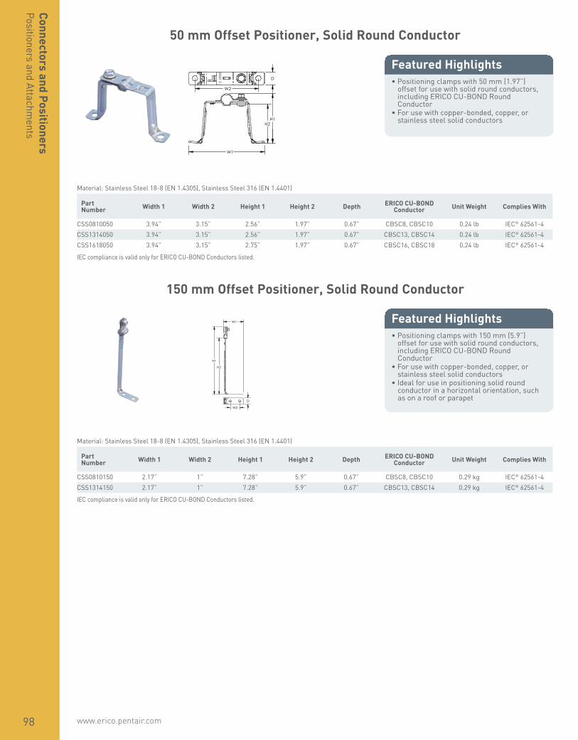
www.erico.pentair.com98
50 mm Offset Positioner, Solid Round Conductor
• Positioning clamps with 50 mm (1.97”) offset for use with solid round conductors, including ERICO CU-BOND Round Conductor
• For use with copper-bonded, copper, or stainless steel solid conductors
Featured Highlights
H1
D
W1
W2
H2
Material: Stainless Steel 18-8 (EN 1.4305), Stainless Steel 316 (EN 1.4401) Part Number Width 1 Width 2 Height 1 Height 2 Depth ERICO CU-BOND
Conductor Unit Weight Complies With
CSS0810050 3.94” 3.15” 2.56” 1.97” 0.67” CBSC8, CBSC10 0.24 lb IEC® 62561-4CSS1314050 3.94” 3.15” 2.56” 1.97” 0.67” CBSC13, CBSC14 0.24 lb IEC® 62561-4CSS1618050 3.94” 3.15” 2.75” 1.97” 0.67” CBSC16, CBSC18 0.24 lb IEC® 62561-4
IEC compliance is valid only for ERICO CU-BOND Conductors listed.
150 mm Offset Positioner, Solid Round Conductor
• Positioning clamps with 150 mm (5.9”) offset for use with solid round conductors, including ERICO CU-BOND Round Conductor
• For use with copper-bonded, copper, or stainless steel solid conductors
• Ideal for use in positioning solid round conductor in a horizontal orientation, such as on a roof or parapet
Featured Highlights
H1
W1
D
H2
W2
Material: Stainless Steel 18-8 (EN 1.4305), Stainless Steel 316 (EN 1.4401) Part Number Width 1 Width 2 Height 1 Height 2 Depth ERICO CU-BOND
Conductor Unit Weight Complies With
CSS0810150 2.17” 1” 7.28” 5.9” 0.67” CBSC8, CBSC10 0.29 kg IEC® 62561-4CSS1314150 2.17” 1” 7.28” 5.9” 0.67” CBSC13, CBSC14 0.29 kg IEC® 62561-4
IEC compliance is valid only for ERICO CU-BOND Conductors listed.
Connectors and PositionersPositioners and Attachm
ents
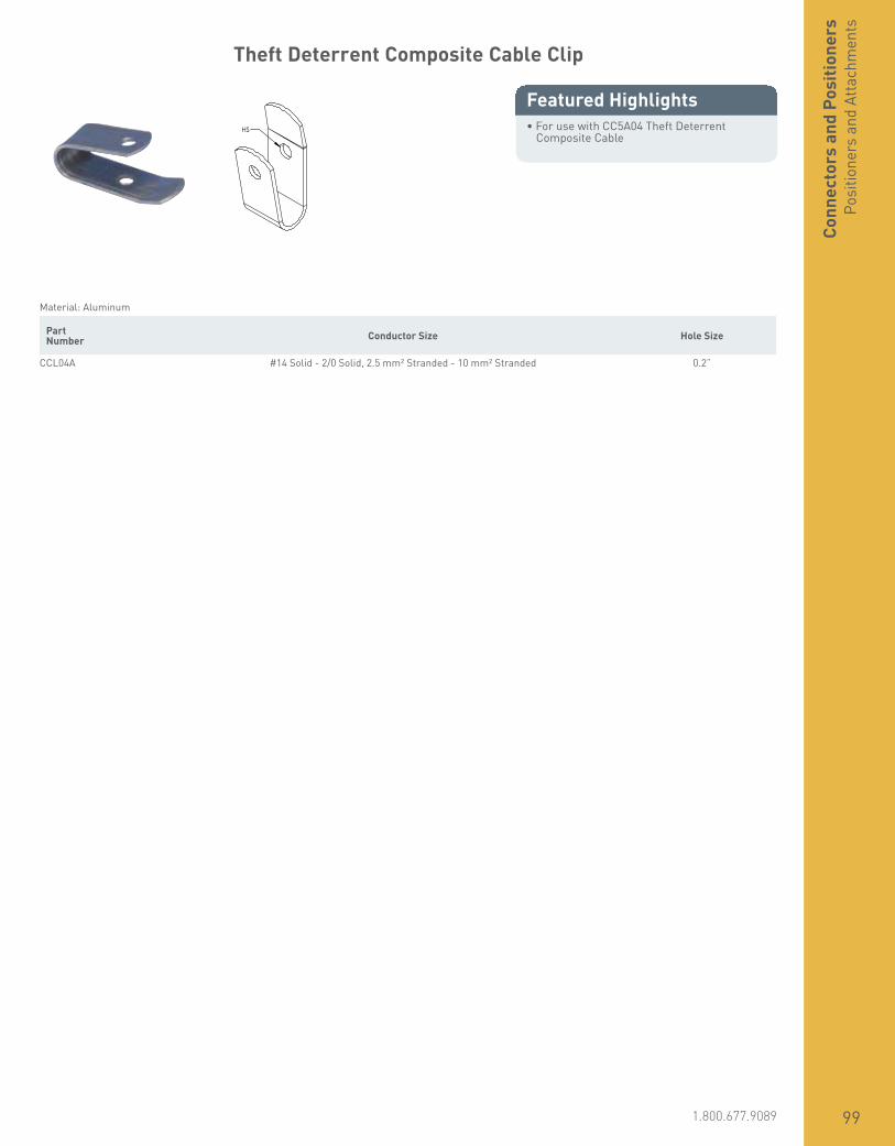
www.erico.pentair.com 1.800.677.9089 99
Theft Deterrent Composite Cable Clip
• For use with CC5A04 Theft Deterrent Composite Cable
Featured Highlights HS
Material: Aluminum Part Number Conductor Size Hole Size
CCL04A #14 Solid - 2/0 Solid, 2.5 mm² Stranded - 10 mm² Stranded 0.2”
Conn
ecto
rs a
nd P
ositi
oner
sPo
sitio
ners
and
Atta
chm
ents

www.erico.pentair.com100

101www.erico.pentair.com 1.800.831.7133
CONDUCTORS
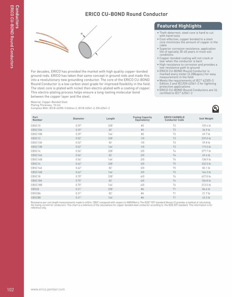
www.erico.pentair.com 1.800.677.9089102
Conductors
ERICO CU-BOND Round Conductor
• Theft-deterrent; steel core is hard to cut with hand tools
• Cost-effective; copper bonded to a steel core minimizes the amount of copper in the cable
• Superior corrosion resistance; application life of typically 30-40 years in most soil conditions
• Copper-bonded coating will not crack or tear when the conductor is bent
• High resistance to corrosion and provides a low-resistance path to ground
• ERICO CU-BOND Round Conductor is marked every meter (3.28') for easy measurement in the field
• Meets the requirements of IEC® 62305-3 Edition 2 and IEC/EN 62561-2 for lightning protection applications
• ERICO CU-BOND Round Conductors are UL certified to IEC® 62561-2
Featured Highlights
For decades, ERICO has provided the market with high quality copper-bonded ground rods. ERICO has taken that same concept in ground rods and made this into a revolutionary new grounding conductor. The core of the ERICO CU-BOND Round Conductor is a low carbon steel grade for improved flexibility in the field. The steel core is plated with nickel then electro-plated with a coating of copper. This electro-plating process helps ensure a long-lasting molecular bond between the copper layer and the steel.
Ø
Material: Copper-Bonded SteelPlating Thickness: 10 milComplies With: IEC® 62305-3 Edition 2; IEC® 62561-2; EN 62561-2
Part Number Diameter Length Fusing Capacity
EquivalencyERICO CADWELD Conductor Code Unit Weight
CBSC10 0.39” 328’ #2 T2 139.4 lbCBSC10A 0.39” 82’ #2 T2 34.9 lbCBSC10B 0.39” 164’ #2 T2 69.7 lbCBSC13 0.52” 328’ 1/0 T3 239.0 lbCBSC13A 0.52” 82’ 1/0 T3 59.8 lbCBSC13B 0.52” 164’ 1/0 T3 119.5 lbCBSC14 0.56” 328’ 2/0 T4 277.7 lbCBSC14A 0.56” 82’ 2/0 T4 69.4 lbCBSC14B 0.56” 164’ 2/0 T4 138.9 lbCBSC16 0.62” 328’ 3/0 T5 332.5 lbCBSC16A 0.62” 82’ 3/0 T5 83.1 lbCBSC16B 0.62” 164’ 3/0 T5 166.3 lbCBSC18 0.70” 328’ 4/0 T6 427.0 lbCBSC18A 0.70” 82’ 4/0 T6 106.8 lbCBSC18B 0.70” 164’ 4/0 T6 213.5 lbCBSC8 0.31” 328’ #4 T1 86.6 lbCBSC8A 0.31” 82’ #4 T1 21.7 lbCBSC8B 0.31” 164’ #4 T1 43.3 lb
Resistance per unit length measurements made in mΩ/m, CBSC compared with respect to AWG/Metric.The IEEE® 837 standard (Annex C) provides a method of calculating the fusing current for conductors. This chart is a reference of the calculations for copper-bonded steel conductor according to the IEEE 837 standard. This information is for reference only.
ConductorsERICO CU
-BOND Round Conductors

www.erico.pentair.com 1.800.677.9089 103
Conductor Physical Size Comparison
Conductor Size Approximate Diameter
Approximate Diameter
Cross Section Cross Section
#4 AWG 0.235” 5.97 mm - -
25 mm² 0.266” 6.76 mm - -
#2 AWG 0.292” 7.42 mm - -
35 mm² 0.301” 7.65 mm - -
CBSC8 0.315” 8 mm 0.08 in² 50.27 mm²
50 mm² 0.35” 8.89 mm - -
1/0 AWG 0.373” 9.47 mm - -
CBSC10 0.394” 10 mm 0.12 in² 78.52 mm²
2/0 AWG 0.419” 10.64 mm - -
70 mm² 0.421” 10.69 mm - -
3/0 AWG 0.41” 10.4 mm - -
95 mm² 0.49” 12.47 mm - -
CBSC13 0.52” 13.2 mm 0.21 in² 138.07 mm²
4/0 AWG 0.528” 13.41 mm - -
CBSC14 0.56” 14.2 mm 0.25 in² 158.90 mm²
120 mm² 0.56” 14.22 mm - -
250 MCM 0.575” 14.61 mm - -
CBSC16 0.618” 15.7 mm 0.31 in² 199.84 mm²
150 mm² 0.62” 15.75 mm - -
300 MCM 0.629” 15.98 mm - -
185 mm² 0.695” 17.65 mm - -
CBSC18 0.697” 17.7 mm 0.38 in² 243.27 mm²
Conductivity Comparison
Part Number AWG (Ω/km) CBSC Resistance per Length Comparison
mm² (Ω/km) CBSC Resistance per Length Comparison
CBSC181/0 AWG 118.52% 50 mm² 110.82%
2 AWG 74.54% 35 mm² 77.57%
CBSC162 AWG 102.20% 35 mm² 106.36%
4 AWG 64.27% 25 mm² 75.97%
CBSC142 AWG 137.78% 25 mm² 102.42%
4 AWG 86.65% 16 mm² 65.55%
CBSC132 AWG 134.46% 25 mm² 99.95%
4 AWG 84.56% 16 mm² 63.97%
CBSC104 AWG 132.25% 16 mm² 100.05%
6 AWG 83.17% 10 mm² 62.53%
CBSC86 AWG 107.85% 16 mm² 129.73%
8 AWG 67.83% 10 mm² 81.08%Co
nduc
tors
ERIC
O CU
-BON
D Ro
und
Cond
ucto
rs
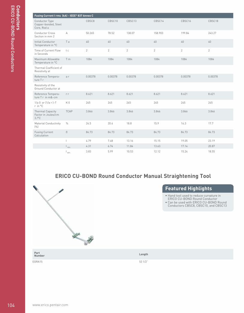
www.erico.pentair.com104
ERICO CU-BOND Round Conductor Manual Straightening Tool
• Hand tool used to reduce curvature in ERICO CU-BOND Round Conductor
• Can be used with ERICO CU-BOND Round Conductors CBSC8, CBSC10, and CBSC13
Featured Highlights
Part Number Length
EGRA15 53 1/2”
Fusing Current I rms (kA) - IEEE® 837 Annex C
Conductor Type Copper-bonded, Steel Core, Rod a
CBSC8 CBSC10 CBSC13 CBSC14 CBSC16 CBSC18
Conductor Cross Section in mm 2
A 50.265 78.52 138.07 158.903 199.84 243.27
Initial Conductor Temperature in °C
T a 40 40 40 40 40 40
Time of Current Flow in Seconds
t c 2 2 2 2 2 2
Maximum Allowable Temperature in °C
T m 1084 1084 1084 1084 1084 1084
Thermal Coefficient of Resistivity at
Reference Tempera-ture T r
a r 0.00378 0.00378 0.00378 0.00378 0.00378 0.00378
Resistivity of the Ground Conductor at
Reference Tempera-ture T r in m&-cm
r r 8.621 8.621 8.621 8.621 8.621 8.621
1/a 0 or (1/a r )–T r in °C
K 0 245 245 245 245 245 245
Thermal Capacity Factor in Joules/cm 3 /°C
TCAP 3.846 3.846 3.846 3.846 3.846 3.846
Material Conductivity (%)
% 24.5 20.4 18.8 15.9 16.3 17.7
Fusing Current Calculation
ß 84.73 84.73 84.73 84.73 84.73 84.73
I 4.79 7.48 13.16 15.15 19.05 23.19
I 90% 4.31 6.74 11.84 13.63 17.14 20.87
I 80% 3.83 5.99 10.53 12.12 15.24 18.55
ConductorsERICO CU
-BOND Round Conductors

www.erico.pentair.com 1.800.677.9089 105
Cond
ucto
rsER
ICO
CU-B
OND
Roun
d Co
nduc
tors
ERICO CU-BOND Round Conductor Powered Straightening Tool
• Operates on 220/240V (single phase) or 110/120V with step-up transformer included on CBSCSSMT
• Two operating modes: Automatic with speed control and manual forward/reverse
• Interchangeable rollers allow the machine to straighten CBSC8, CBSC10, and CBSC13
• Manual straightening bar straightens the first few sections of ERICO CU-BOND Round Conductor prior to feeding it into the machine
• Enclosure covers moving internal parts• Safety switch for emergency shutoff• Includes control rod to calibrate setup of the
straightening machine• Designed to be able to be moved on site by
a forklift• Wheels and collapsible handles allow for
easy movement on the jobsite• Add-on uncoiler holds ERICO CU-BOND
Round Conductor coils and provides a method of feeding material into the machine and gives repeatable and precise straightness results
Featured Highlights
H1
W1
H2
L1
W2
L2
Part Number Length 1 Length 2 Width 1 Width 2 Height 1 Height 2 Operating Voltage Unit Weight
CBSCSSM 43 1/4” 44 1/2” 20” 44 1/2” 39 1/4” 40” 220/240V 507 lbCBSCSSMT 43 1/4” 44 1/2” 20” 44 1/2” 39 1/4” 40” 110/120V - 220/240V 507 lb
Spare parts are available for order. Contact your ERICO representative for more information.
Fusing Current I rms (kA) - IEEE® 837 Annex C
Conductor Type Copper-bonded, Steel Core, Rod a
CBSC8 CBSC10 CBSC13 CBSC14 CBSC16 CBSC18
Conductor Cross Section in mm 2
A 50.265 78.52 138.07 158.903 199.84 243.27
Initial Conductor Temperature in °C
T a 40 40 40 40 40 40
Time of Current Flow in Seconds
t c 2 2 2 2 2 2
Maximum Allowable Temperature in °C
T m 1084 1084 1084 1084 1084 1084
Thermal Coefficient of Resistivity at
Reference Tempera-ture T r
a r 0.00378 0.00378 0.00378 0.00378 0.00378 0.00378
Resistivity of the Ground Conductor at
Reference Tempera-ture T r in m&-cm
r r 8.621 8.621 8.621 8.621 8.621 8.621
1/a 0 or (1/a r )–T r in °C
K 0 245 245 245 245 245 245
Thermal Capacity Factor in Joules/cm 3 /°C
TCAP 3.846 3.846 3.846 3.846 3.846 3.846
Material Conductivity (%)
% 24.5 20.4 18.8 15.9 16.3 17.7
Fusing Current Calculation
ß 84.73 84.73 84.73 84.73 84.73 84.73
I 4.79 7.48 13.16 15.15 19.05 23.19
I 90% 4.31 6.74 11.84 13.63 17.14 20.87
I 80% 3.83 5.99 10.53 12.12 15.24 18.55

www.erico.pentair.com106
ConductorsERICO CU
-BOND Com
posite Cable
ERICO CU-BOND Composite Cable
• Outer strands comprised of tinned copper-bonded steel for theft deterrence and improved corrosion resistance
• Inner copper stranding is tinned for superior corrosion resistance
• Copper stranding inside of conductor increases conductivity and conductor flexibility
• Copper strands are hidden by outer galvanized steel strands
• Available in three sizes/configurations with electrical equivalency to 4, 2/0 and 4/0 AWG copper
• Suitable for direct burial applications• More flexible and easier to work with than
copper clad steel conductors
Featured Highlights
ERICO CU-BOND is a bare concentric stranded conductor that consists of peripheral tinned copper plated steel which protects and conceals the internal copper stranding.
Material: Copper, Copper-Bonded SteelFinish: TinnedInsulated: No
Part Number Stranding Resistance Fusing Capacity
EquivalencyCable
DiameterCable
LengthConductor
CodeERICO
HAMMERLOCKUnit
Weight
CC5A05CB(19) Strands:
(3) Tinned Copper, (16) Tin Plated Copper-
Bonded Steel0.374 Ω/1000’ #4 0.320” 250’ S1 EHL58C2G,
EHL34C2G 61 lb
CC5A20CB(154) Strands:
(133) Tinned Copper, (21) Tin Plated Copper-
Bonded Steel0.087 Ω/1000’ 2/0 0.524” 200’ S5 113 lb
CC5A40CB(161) Strands:
(133) Tinned Copper, (27) Tinned Copper-
Bonded Steel0.056 Ω/1000’ 4/0 0.651” 200’ S7 174 lb
Weight does not include reel.
Insulated Copper Conductor
• Insulated copper conductor is compacted, so the diameter is smaller than conventional insulated copper conductor
• Green and yellow insulation protects the strands of the conductor
Featured HighlightsOD
Material: Copper, Polyvinylchloride Part Number
Conductor Size
Number of Wires
Wire Diameter
Cable Diameter
Outer Diameter
Cable Length
Insulation Thickness
Unit Weight
Conductor Type: Concentric, CompactedICECH120C 120 mm² Stranded 24 0.11” 0.508” 0.63” 1,640’ 0.04” 1,279 lbICECH150C 150 mm² Stranded 30 0.11” 0.557” 0.70” 1,640’ 0.04” 1,698 lbICECH185C 185 mm² Stranded 37 0.11” 0.624” 0.78” 1,640’ 0.04” 2,315 lb

www.erico.pentair.com 1.800.677.9089 107
Cond
ucto
rsN
on-I
nsul
ated
Rou
nd C
ondu
ctor
s
Part Number
Conductor Size
Number of Wires
Wire Diameter
Cable Diameter
Outer Diameter
Cable Length
Insulation Thickness
Unit Weight
ICECH240C 240 mm² Stranded 37 0.11” 0.719” 0.89” 1,640’ 0.04” 3,009 lbICECH50C 50 mm² Stranded 10 0.11” 0.321” 0.43” 164’ 0.04” 57 lbICECH70C 70 mm² Stranded 14 0.11” 0.380” 0.49” 1,640’ 0.04” 794 lbICECH95C 95 mm² Stranded 19 0.11” 0.447” 0.57” 1,640’ 0.04” 1,080 lb
Conductor Type: Concentric, Non-CompactedICECH25 25 mm² Stranded 7 0.90” 0.230” 0.33” 164’ 0.04” 29 lb
Outer diameter dimensions are approximate.
Non-Insulated Solid Conductor
• Solid cable for a variety of applications• Available in smaller spool sizes for
convenience• LPA and LPC parts are used for lightning
protection system downconductor or grounding applications
Featured Highlights
Ø
Part Number Length Cross Section Conductor Size Diameter Unit Weight Certifications
Material: Copper — Finish: BareA809A06F100 100’ 41.70 kcmil #4 Solid 0.204” 0.038 lbLPC151250 250’ 26.24 kcmil #6 Solid 0.161” 0.024 lb ULLPC151CTO 26.24 kcmil #6 Solid 0.161” 0.024 lb ULLPC154CTO 66.36 kcmil #2 Solid 0.325” 0.062 lb ULRCEC6 328’ 55.80 kcmil 6 mm² Solid 0.236” 0.050 lb
Material: Copper — Finish: TinnedLPC154LCTO 66.36 kcmil #2 Solid 0.325” 0.062 lb UL
Unit weight is per foot (0.3048 m).Cut-to-order (CTO) lengths are available for an additional charge.
Non-Insulated Stranded Conductor
• Stranded pure electrolytic copper cable conductors for a variety of applications
• Stranded grounded conductor cut into standard lengths for easy field installation
Featured Highlights
Ø
Material: CopperConductor Type: Concentric
Part Number Number of Wires Wire Diameter Diameter Length Cross Section Conductor Size Unit Weight
A800A09F100 19 0.084” 0.500” 100’ 133.0 kcmil 2/0 Stranded 41.1 lbA800A09F65 19 0.084” 0.500” 65’ 133.0 kcmil 2/0 Stranded 26.7 lbA800A22F100 19 0.106” 0.528” 100’ 211.6 kcmil 4/0 Stranded 65.0 lb
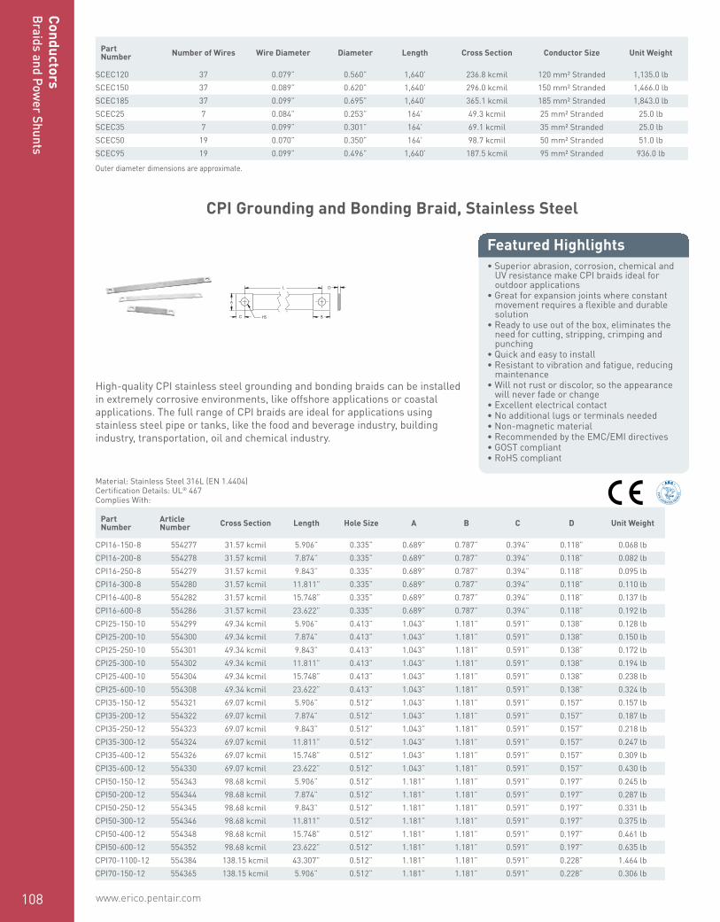
www.erico.pentair.com108
ConductorsBraids and Pow
er Shunts
Part Number Number of Wires Wire Diameter Diameter Length Cross Section Conductor Size Unit Weight
SCEC120 37 0.079” 0.560” 1,640’ 236.8 kcmil 120 mm² Stranded 1,135.0 lbSCEC150 37 0.089” 0.620” 1,640’ 296.0 kcmil 150 mm² Stranded 1,466.0 lbSCEC185 37 0.099” 0.695” 1,640’ 365.1 kcmil 185 mm² Stranded 1,843.0 lbSCEC25 7 0.084” 0.253” 164’ 49.3 kcmil 25 mm² Stranded 25.0 lbSCEC35 7 0.099” 0.301” 164’ 69.1 kcmil 35 mm² Stranded 25.0 lbSCEC50 19 0.070” 0.350” 164’ 98.7 kcmil 50 mm² Stranded 51.0 lbSCEC95 19 0.099” 0.496” 1,640’ 187.5 kcmil 95 mm² Stranded 936.0 lb
Outer diameter dimensions are approximate.
CPI Grounding and Bonding Braid, Stainless Steel
• Superior abrasion, corrosion, chemical and UV resistance make CPI braids ideal for outdoor applications
• Great for expansion joints where constant movement requires a flexible and durable solution
• Ready to use out of the box, eliminates the need for cutting, stripping, crimping and punching
• Quick and easy to install• Resistant to vibration and fatigue, reducing
maintenance• Will not rust or discolor, so the appearance
will never fade or change• Excellent electrical contact• No additional lugs or terminals needed• Non-magnetic material• Recommended by the EMC/EMI directives• GOST compliant• RoHS compliant
Featured Highlights
High-quality CPI stainless steel grounding and bonding braids can be installed in extremely corrosive environments, like offshore applications or coastal applications. The full range of CPI braids are ideal for applications using stainless steel pipe or tanks, like the food and beverage industry, building industry, transportation, oil and chemical industry.
BC
L D
HS
A
Material: Stainless Steel 316L (EN 1.4404)Certification Details: UL® 467Complies With:
Part Number
ArticleNumber Cross Section Length Hole Size A B C D Unit Weight
CPI16-150-8 554277 31.57 kcmil 5.906” 0.335” 0.689” 0.787” 0.394” 0.118” 0.068 lbCPI16-200-8 554278 31.57 kcmil 7.874” 0.335” 0.689” 0.787” 0.394” 0.118” 0.082 lbCPI16-250-8 554279 31.57 kcmil 9.843” 0.335” 0.689” 0.787” 0.394” 0.118” 0.095 lbCPI16-300-8 554280 31.57 kcmil 11.811” 0.335” 0.689” 0.787” 0.394” 0.118” 0.110 lbCPI16-400-8 554282 31.57 kcmil 15.748” 0.335” 0.689” 0.787” 0.394” 0.118” 0.137 lbCPI16-600-8 554286 31.57 kcmil 23.622” 0.335” 0.689” 0.787” 0.394” 0.118” 0.192 lbCPI25-150-10 554299 49.34 kcmil 5.906” 0.413” 1.043” 1.181” 0.591” 0.138” 0.128 lbCPI25-200-10 554300 49.34 kcmil 7.874” 0.413” 1.043” 1.181” 0.591” 0.138” 0.150 lbCPI25-250-10 554301 49.34 kcmil 9.843” 0.413” 1.043” 1.181” 0.591” 0.138” 0.172 lbCPI25-300-10 554302 49.34 kcmil 11.811” 0.413” 1.043” 1.181” 0.591” 0.138” 0.194 lbCPI25-400-10 554304 49.34 kcmil 15.748” 0.413” 1.043” 1.181” 0.591” 0.138” 0.238 lbCPI25-600-10 554308 49.34 kcmil 23.622” 0.413” 1.043” 1.181” 0.591” 0.138” 0.324 lbCPI35-150-12 554321 69.07 kcmil 5.906” 0.512” 1.043” 1.181” 0.591” 0.157” 0.157 lbCPI35-200-12 554322 69.07 kcmil 7.874” 0.512” 1.043” 1.181” 0.591” 0.157” 0.187 lbCPI35-250-12 554323 69.07 kcmil 9.843” 0.512” 1.043” 1.181” 0.591” 0.157” 0.218 lbCPI35-300-12 554324 69.07 kcmil 11.811” 0.512” 1.043” 1.181” 0.591” 0.157” 0.247 lbCPI35-400-12 554326 69.07 kcmil 15.748” 0.512” 1.043” 1.181” 0.591” 0.157” 0.309 lbCPI35-600-12 554330 69.07 kcmil 23.622” 0.512” 1.043” 1.181” 0.591” 0.157” 0.430 lbCPI50-150-12 554343 98.68 kcmil 5.906” 0.512” 1.181” 1.181” 0.591” 0.197” 0.245 lbCPI50-200-12 554344 98.68 kcmil 7.874” 0.512” 1.181” 1.181” 0.591” 0.197” 0.287 lbCPI50-250-12 554345 98.68 kcmil 9.843” 0.512” 1.181” 1.181” 0.591” 0.197” 0.331 lbCPI50-300-12 554346 98.68 kcmil 11.811” 0.512” 1.181” 1.181” 0.591” 0.197” 0.375 lbCPI50-400-12 554348 98.68 kcmil 15.748” 0.512” 1.181” 1.181” 0.591” 0.197” 0.461 lbCPI50-600-12 554352 98.68 kcmil 23.622” 0.512” 1.181” 1.181” 0.591” 0.197” 0.635 lbCPI70-1100-12 554384 138.15 kcmil 43.307” 0.512” 1.181” 1.181” 0.591” 0.228” 1.464 lbCPI70-150-12 554365 138.15 kcmil 5.906” 0.512” 1.181” 1.181” 0.591” 0.228” 0.306 lb

www.erico.pentair.com 1.800.677.9089 109
Cond
ucto
rsBr
aids
and
Pow
er S
hunt
s
Part Number
ArticleNumber Cross Section Length Hole Size A B C D Unit Weight
CPI70-200-12 554366 138.15 kcmil 7.874” 0.512” 1.181” 1.181” 0.591” 0.228” 0.368 lbCPI70-250-12 554367 138.15 kcmil 9.843” 0.512” 1.181” 1.181” 0.591” 0.228” 0.428 lbCPI70-300-12 554368 138.15 kcmil 11.811” 0.512” 1.181” 1.181” 0.591” 0.228” 0.489 lbCPI70-400-12 554370 138.15 kcmil 15.748” 0.512” 1.181” 1.181” 0.591” 0.228” 0.611 lbCPI70-600-12 554374 138.15 kcmil 23.622” 0.512” 1.181” 1.181” 0.591” 0.228” 0.855 lbCPI70-800-12 554378 138.15 kcmil 31.496” 0.512” 1.181” 1.181” 0.591” 0.228” 1.098 lb
MBJ Grounding and Bonding Braid, Tinned Copper
• Complete range of earth/ground flexible connections from 6 - 100 mm² (11.84 - 197.35 kcmil) cross section and from 100 - 500 mm (3.937” - 19.685”) length
• Integral palm, without tin or crimped lugs for superior electrical contact and tensile strength resistance
• Resistant to vibration and fatigue, reducing maintenance
• Provides weight savings, material savings and lower impedance when compared to similar lugged cables with insulation
• Ready to use out of the box, eliminates the need for cutting, stripping, crimping and punching
• Quick and easy to install• Recommended by the EMC/EMI directives
and less impedance than cables• GOST compliant• RoHS compliant
Featured Highlights
MBJ Grounding and Bonding Braids are a reliable and convenient grounding solution for applications that require flexibility and durability. The tinned copper ground braids with massivated palms come ready to install without any additional cutting, stripping, crimping or punching and do not require the addition of tin or crimped lugs. The proprietary manufacturing process optimizes the electrical contact between each wire and helps eliminate moisture issues in the palms, preventing corrosion and lengthening the useful life of the braid.
A
B HS
T
L
Material: CopperFinish: TinnedWorking Temperature: 221 °F MaxComplies With:
Part Number
ArticleNumber Intensity Thickness Cross Section Length Hole Size A B Unit Weight
MBJ100-250-16 563500 349 A 0.157” 197.35 kcmil 9.843” 0.650” 1.969” 2.165” 0.559 lbMBJ100-250-30 563510 349 A 0.157” 197.35 kcmil 9.843” 1.201” 1.969” 2.165” 0.559 lbMBJ100-500-16 563520 349 A 0.157” 197.35 kcmil 19.685” 0.650” 1.969” 2.165” 1.118 lbMBJ100-500-30 563530 349 A 0.157” 197.35 kcmil 19.685” 1.201” 1.969” 2.165” 1.118 lbMBJ10-200-6 556930 75 A 0.043” 19.74 kcmil 7.874” 0.256” 0.433” 0.709” 0.048 lbMBJ10-300-6 556610 75 A 0.043” 19.74 kcmil 11.811” 0.256” 0.433” 0.709” 0.073 lbMBJ16-100-6 563540 120 A 0.059” 31.57 kcmil 3.937” 0.256” 0.591” 0.787” 0.040 lbMBJ16-100-8 556620 120 A 0.059” 31.57 kcmil 3.937” 0.335” 0.591” 0.787” 0.040 lbMBJ16-150-6 563550 120 A 0.059” 31.57 kcmil 5.906” 0.256” 0.591” 0.787” 0.077 lbMBJ16-150-8 556630 120 A 0.059” 31.57 kcmil 5.906” 0.335” 0.591” 0.787” 0.077 lbMBJ16-200-6 563300 120 A 0.059” 31.57 kcmil 7.874” 0.256” 0.591” 0.787” 0.073 lbMBJ16-200-8 556640 120 A 0.059” 31.57 kcmil 7.874” 0.335” 0.591” 0.787” 0.073 lbMBJ16-250-8 556650 120 A 0.059” 31.57 kcmil 9.843” 0.335” 0.591” 0.787” 0.088 lbMBJ16-300-6 563320 120 A 0.059” 31.57 kcmil 11.811” 0.256” 0.591” 0.787” 0.110 lbMBJ16-300-8 556660 120 A 0.059” 31.57 kcmil 11.811” 0.335” 0.591” 0.787” 0.110 lbMBJ16-500-8 556940 120 A 0.059” 31.57 kcmil 19.685” 0.335” 0.591” 0.787” 0.180 lbMBJ25-100-10 556670 150 A 0.059” 49.34 kcmil 3.937” 0.413” 0.866” 1.102” 0.059 lbMBJ25-150-10 556680 150 A 0.059” 49.34 kcmil 5.906” 0.413” 0.866” 1.102” 0.086 lbMBJ25-200-10 556690 150 A 0.059” 49.34 kcmil 7.874” 0.413” 0.866” 1.102” 0.114 lbMBJ25-200-12 563430 150 A 0.059” 49.34 kcmil 7.874” 0.492” 0.866” 1.102” 0.114 lbMBJ25-200-6 563340 150 A 0.059” 49.34 kcmil 7.874” 0.256” 0.866” 1.102” 0.114 lbMBJ25-250-10 556700 150 A 0.059” 49.34 kcmil 9.843” 0.413” 0.866” 1.102” 0.141 lbMBJ25-300-10 556710 150 A 0.059” 49.34 kcmil 11.811” 0.413” 0.866” 1.102” 0.169 lbMBJ25-500-10 556950 150 A 0.059” 49.34 kcmil 19.685” 0.413” 0.866” 1.102” 0.286 lb

www.erico.pentair.com110
ConductorsTape
Part Number
ArticleNumber Intensity Thickness Cross Section Length Hole Size A B Unit Weight
MBJ30-100-10 556720 180 A 0.079” 59.20 kcmil 3.937” 0.413” 0.866” 1.102” 0.070 lbMBJ30-150-10 556730 180 A 0.079” 59.20 kcmil 5.906” 0.413” 0.866” 1.102” 0.103 lbMBJ30-200-10 556740 180 A 0.079” 59.20 kcmil 7.874” 0.413” 0.866” 1.102” 0.136 lbMBJ30-250-10 556750 180 A 0.079” 59.20 kcmil 9.843” 0.413” 0.866” 1.102” 0.165 lbMBJ30-300-10 556760 180 A 0.079” 59.20 kcmil 11.811” 0.413” 0.866” 1.102” 0.202 lbMBJ30-500-10 556960 180 A 0.079” 59.20 kcmil 19.685” 0.413” 0.866” 1.102” 0.341 lbMBJ35-100-10 556770 197 A 0.083” 69.07 kcmil 3.937” 0.413” 0.866” 1.102” 0.081 lbMBJ35-150-10 556780 197 A 0.083” 69.07 kcmil 5.906” 0.413” 0.866” 1.102” 0.119 lbMBJ35-200-10 556790 197 A 0.083” 69.07 kcmil 7.874” 0.413” 0.866” 1.102” 0.158 lbMBJ35-250-10 556800 197 A 0.083” 69.07 kcmil 9.843” 0.413” 0.866” 1.102” 0.196 lbMBJ35-250-25 565000 197 A 0.059” 69.07 kcmil 9.843” 1.004” 1.575” 1.772” 0.196 lbMBJ35-300-10 556810 197 A 0.083” 69.07 kcmil 11.811” 0.413” 0.866” 1.102” 0.242 lbMBJ35-500-10 556970 197 A 0.083” 69.07 kcmil 19.685” 0.413” 0.866” 1.102” 0.396 lbMBJ50-100-10 556820 250 A 0.098” 98.68 kcmil 3.937” 0.413” 1.102” 1.300” 0.114 lbMBJ50-150-10 556830 250 A 0.098” 98.68 kcmil 5.906” 0.413” 1.102” 1.300” 0.169 lbMBJ50-200-10 556840 250 A 0.098” 98.68 kcmil 7.874” 0.413” 1.102” 1.300” 0.264 lbMBJ50-200-12 563440 250 A 0.098” 98.68 kcmil 7.874” 0.492” 1.102” 1.300” 0.264 lbMBJ50-200-16 563360 250 A 0.098” 98.68 kcmil 7.874” 0.650” 1.102” 1.300” 0.242 lbMBJ50-200-18 563370 250 A 0.098” 98.68 kcmil 7.874” 0.728” 1.102” 1.300” 0.242 lbMBJ50-200-6 563350 250 A 0.098” 98.68 kcmil 7.874” 0.256” 1.102” 1.300” 0.264 lbMBJ50-250-10 556850 250 A 0.098” 98.68 kcmil 9.843” 0.413” 1.102” 1.300” 0.279 lbMBJ50-300-10 556860 250 A 0.098” 98.68 kcmil 11.811” 0.413” 1.102” 1.300” 0.337 lbMBJ50-300-16 563390 250 A 0.098” 98.68 kcmil 11.811” 0.650” 1.102” 1.300” 0.330 lbMBJ50-300-18 563400 250 A 0.098” 98.68 kcmil 11.811” 0.728” 1.102” 1.300” 0.308 lbMBJ50-300-6 563380 250 A 0.098” 98.68 kcmil 11.811” 0.256” 1.102” 1.300” 0.330 lbMBJ50-500-10 556980 250 A 0.098” 98.68 kcmil 19.685” 0.413” 1.102” 1.300” 0.561 lbMBJ50-500-12 563560 250 A 0.098” 98.68 kcmil 19.685” 0.492” 1.102” 1.300” 0.561 lbMBJ6-150-6 556600 40 A 0.043” 11.84 kcmil 5.906” 0.256” 0.433” 0.709” 0.022 lbMBJ6-200-6 563410 40 A 0.043” 11.84 kcmil 7.874” 0.256” 0.433” 0.709” 0.037 lbMBJ70-300-10 563460 290 A 0.133” 138.15 kcmil 11.811” 0.413” 1.102” 1.300” 0.462 lbMBJ70-300-12 563420 290 A 0.133” 138.15 kcmil 11.811” 0.492” 1.102” 1.300” 0.462 lbMBJ70-300-16 563470 290 A 0.133” 138.15 kcmil 11.811” 0.650” 1.102” 1.300” 0.440 lbMBJ70-300-22 563480 290 A 0.110” 138.15 kcmil 11.811” 0.886” 1.575” 1.772” 0.440 lbMBJ70-300-6 563450 290 A 0.133” 138.15 kcmil 11.811” 0.256” 1.102” 1.300” 0.462 lbMBJ70-500-10 563490 290 A 0.133” 138.15 kcmil 19.685” 0.413” 1.102” 1.300” 0.748 lb
Tape Conductor
• Lower impedance than equivalent sized round conductor
• Used for lightning protection system downconductor or grounding applications
Featured Highlights
W
L
Material: CopperFinish: Bare
Part Number Length Width Thickness Unit Weight
A811A26F50 50’ 2” 26 GA 0.152 lbA811A26F500 500’ 2” 26 GA 0.152 lbA811A26W4F500 500’ 4” 26 GA 0.231 lbA811C20F100 100’ 3” 20 GA 0.410 lbA811C20F20 20’ 3” 20 GA 0.410 lb

www.erico.pentair.com 1.800.677.9089 111
Cond
ucto
rsTa
pe
Part Number Length Width Thickness Unit Weight
LPC172CTO 3/4” 8 GA 0.110 lb
Cut-to-order (CTO) lengths are available for an additional charge.Unit weight is per meter (3.28’).
Low Impedance Riser
• Used to connect the signal reference grid to equipment
• Welded to the SRG using ERICO CADWELD mold type TW
• Has a lower impedance than a 4/0 AWG copper conductor
Featured Highlights
W
L HS
Material: Copper Part Number Length Width Thickness Hole Size
B802D01A12 12” 2” 26 GA 5/16”B802D01A120 120” 2” 26 GA 5/16”B802D01A24 24” 2” 26 GA 5/16”B802D01A36 36” 2” 26 GA 5/16”B802D01A48 48” 2” 26 GA 5/16”B802D01A5 5” 2” 26 GA 5/16”

www.erico.pentair.com112

113www.erico.pentair.com 1.800.831.7133
GROUNDING & BONDING
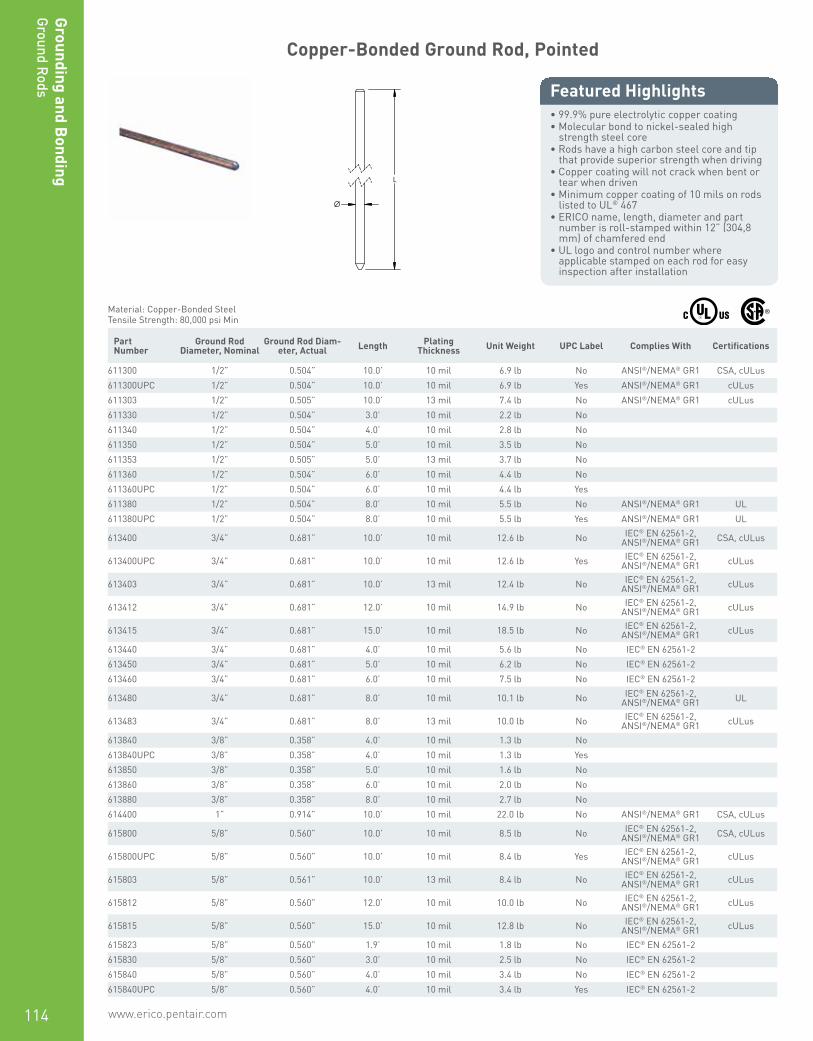
www.erico.pentair.com 1.800.677.9089114
Grounding and Bonding
Ground Rods
Copper-Bonded Ground Rod, Pointed
• 99.9% pure electrolytic copper coating• Molecular bond to nickel-sealed high
strength steel core• Rods have a high carbon steel core and tip
that provide superior strength when driving• Copper coating will not crack when bent or
tear when driven• Minimum copper coating of 10 mils on rods
listed to UL® 467• ERICO name, length, diameter and part
number is roll-stamped within 12” (304,8 mm) of chamfered end
• UL logo and control number where applicable stamped on each rod for easy inspection after installation
Featured Highlights
L
Ø
Material: Copper-Bonded SteelTensile Strength: 80,000 psi Min
Part Number
Ground Rod Diameter, Nominal
Ground Rod Diam-eter, Actual Length Plating
Thickness Unit Weight UPC Label Complies With Certifications
611300 1/2” 0.504” 10.0’ 10 mil 6.9 lb No ANSI®/NEMA® GR1 CSA, cULus611300UPC 1/2” 0.504” 10.0’ 10 mil 6.9 lb Yes ANSI®/NEMA® GR1 cULus611303 1/2” 0.505” 10.0’ 13 mil 7.4 lb No ANSI®/NEMA® GR1 cULus611330 1/2” 0.504” 3.0’ 10 mil 2.2 lb No611340 1/2” 0.504” 4.0’ 10 mil 2.8 lb No611350 1/2” 0.504” 5.0’ 10 mil 3.5 lb No611353 1/2” 0.505” 5.0’ 13 mil 3.7 lb No611360 1/2” 0.504” 6.0’ 10 mil 4.4 lb No611360UPC 1/2” 0.504” 6.0’ 10 mil 4.4 lb Yes611380 1/2” 0.504” 8.0’ 10 mil 5.5 lb No ANSI®/NEMA® GR1 UL611380UPC 1/2” 0.504” 8.0’ 10 mil 5.5 lb Yes ANSI®/NEMA® GR1 UL
613400 3/4” 0.681” 10.0’ 10 mil 12.6 lb No IEC® EN 62561-2, ANSI®/NEMA® GR1 CSA, cULus
613400UPC 3/4” 0.681” 10.0’ 10 mil 12.6 lb Yes IEC® EN 62561-2, ANSI®/NEMA® GR1 cULus
613403 3/4” 0.681” 10.0’ 13 mil 12.4 lb No IEC® EN 62561-2, ANSI®/NEMA® GR1 cULus
613412 3/4” 0.681” 12.0’ 10 mil 14.9 lb No IEC® EN 62561-2, ANSI®/NEMA® GR1 cULus
613415 3/4” 0.681” 15.0’ 10 mil 18.5 lb No IEC® EN 62561-2, ANSI®/NEMA® GR1 cULus
613440 3/4” 0.681” 4.0’ 10 mil 5.6 lb No IEC® EN 62561-2613450 3/4” 0.681” 5.0’ 10 mil 6.2 lb No IEC® EN 62561-2613460 3/4” 0.681” 6.0’ 10 mil 7.5 lb No IEC® EN 62561-2
613480 3/4” 0.681” 8.0’ 10 mil 10.1 lb No IEC® EN 62561-2, ANSI®/NEMA® GR1 UL
613483 3/4” 0.681” 8.0’ 13 mil 10.0 lb No IEC® EN 62561-2, ANSI®/NEMA® GR1 cULus
613840 3/8” 0.358” 4.0’ 10 mil 1.3 lb No613840UPC 3/8” 0.358” 4.0’ 10 mil 1.3 lb Yes613850 3/8” 0.358” 5.0’ 10 mil 1.6 lb No613860 3/8” 0.358” 6.0’ 10 mil 2.0 lb No613880 3/8” 0.358” 8.0’ 10 mil 2.7 lb No614400 1” 0.914” 10.0’ 10 mil 22.0 lb No ANSI®/NEMA® GR1 CSA, cULus
615800 5/8” 0.560” 10.0’ 10 mil 8.5 lb No IEC® EN 62561-2, ANSI®/NEMA® GR1 CSA, cULus
615800UPC 5/8” 0.560” 10.0’ 10 mil 8.4 lb Yes IEC® EN 62561-2, ANSI®/NEMA® GR1 cULus
615803 5/8” 0.561” 10.0’ 13 mil 8.4 lb No IEC® EN 62561-2, ANSI®/NEMA® GR1 cULus
615812 5/8” 0.560” 12.0’ 10 mil 10.0 lb No IEC® EN 62561-2, ANSI®/NEMA® GR1 cULus
615815 5/8” 0.560” 15.0’ 10 mil 12.8 lb No IEC® EN 62561-2, ANSI®/NEMA® GR1 cULus
615823 5/8” 0.560” 1.9’ 10 mil 1.8 lb No IEC® EN 62561-2615830 5/8” 0.560” 3.0’ 10 mil 2.5 lb No IEC® EN 62561-2615840 5/8” 0.560” 4.0’ 10 mil 3.4 lb No IEC® EN 62561-2615840UPC 5/8” 0.560” 4.0’ 10 mil 3.4 lb Yes IEC® EN 62561-2

www.erico.pentair.com 1.800.677.9089 115
Grou
ndin
g an
d B
ondi
ngGr
ound
Rod
s
Part Number
Ground Rod Diameter, Nominal
Ground Rod Diam-eter, Actual Length Plating
Thickness Unit Weight UPC Label Complies With Certifications
615843 5/8” 0.561” 4.0’ 13 mil 3.4 lb No IEC® EN 62561-2615850 5/8” 0.560” 5.0’ 10 mil 4.2 lb No IEC® EN 62561-2615853 5/8” 0.561” 5.0’ 13 mil 4.5 lb No IEC® EN 62561-2615860 5/8” 0.560” 6.0’ 10 mil 5.1 lb No IEC® EN 62561-2615860UPC 5/8” 0.560” 6.0’ 10 mil 5.1 lb Yes IEC® EN 62561-2615863 5/8” 0.561” 6.0’ 13 mil 5.4 lb No IEC® EN 62561-2
615880 5/8” 0.560” 8.0’ 10 mil 6.8 lb No IEC® EN 62561-2, ANSI®/NEMA® GR1 UL
615880UPC 5/8” 0.560” 8.0’ 10 mil 6.8 lb Yes IEC® EN 62561-2, ANSI®/NEMA® GR1 UL
615883 5/8” 0.561” 8.0’ 13 mil 6.8 lb No IEC® EN 62561-2, ANSI®/NEMA® GR1 UL
615883UPC 5/8” 0.561” 8.0’ 13 mil 6.8 lb Yes IEC® EN 62561-2, ANSI®/NEMA® GR1 UL
For rods to be listed to UL® 467, they must be at least 8’ (2.43 m) in length.IEC® EN 62561-2 supercedes EN 50164-2.Additional lengths available.
Copper-Bonded Ground Rod, Sectional
• Cold-rolled threads with continuous, unbroken grain flows preserve copper coating and are stronger than cut threads
• 99.9% pure electrolytic copper coating• Molecular bond to nickel-sealed high
strength steel core• Rods have a high carbon steel core and tip
that provide superior strength when driving• Copper coating will not crack when bent or
tear when driven• Minimum copper coating of 10 mils on rods
listed to UL® 467• ERICO name, length, diameter and part
number is roll-stamped within 12” (304,8 mm) of chamfered end
• UL logo and control number where applicable stamped on each rod for easy inspection after installation
Featured Highlights
L
Ø
TS
Material: Copper-Bonded SteelTensile Strength: 80,000 psi Min
Part Number
Ground Rod Diameter, Nominal
Ground Rod Diameter, Actual Thread Size Length Plating
ThicknessUnit
Weight Complies With Certifications
Thread Location: Chamfered (Non-Pointed) End Only625850 5/8” 0.560” 5/8 UNC 5’ 10 mil 4.2 lb IEC® EN 62561-2
Thread Location: Pointed and Chamfered Ends631300 1/2” 0.504” 9/16 UNC 10’ 10 mil 6.9 lb ANSI®/NEMA® GR1 CSA, cULus631303 1/2” 0.505” 9/16 UNC 10’ 13 mil 7.0 lb ANSI®/NEMA® GR1 cULus631340 1/2” 0.504” 9/16 UNC 4’ 10 mil 2.7 lb631350 1/2” 0.504” 9/16 UNC 5’ 10 mil 3.5 lb631360 1/2” 0.504” 9/16 UNC 6’ 10 mil 4.2 lb631380 1/2” 0.504” 9/16 UNC 8’ 10 mil 5.4 lb ANSI®/NEMA® GR1 UL
633400 3/4” 0.680” 3/4 UNC 10’ 10 mil 12.5 lb ANSI®/NEMA® GR1, IEC® EN 62561-2 CSA, cULus
633403 3/4” 0.681” 3/4 UNC 10’ 13 mil 12.5 lb ANSI®/NEMA® GR1, IEC® EN 62561-2 cULus
633415 3/4” 0.680” 3/4 UNC 15’ 10 mil 18.8 lb ANSI®/NEMA® GR1, IEC® EN 62561-2 cULus
633430 3/4” 0.680” 3/4 UNC 3’ 10 mil 3.8 lb IEC® EN 62561-2633440 3/4” 0.680” 3/4 UNC 4’ 10 mil 4.9 lb IEC® EN 62561-2633450 3/4” 0.680” 3/4 UNC 5’ 10 mil 6.2 lb IEC® EN 62561-2633460 3/4” 0.680” 3/4 UNC 6’ 10 mil 7.1 lb IEC® EN 62561-2633463 3/4” 0.681” 3/4 UNC 6’ 13 mil 7.1 lb IEC® EN 62561-2633470 3/4” 0.680” 3/4 UNC 7’ 10 mil 8.5 lb IEC® EN 62561-2
633480 3/4” 0.680” 3/4 UNC 8’ 10 mil 9.6 lb ANSI®/NEMA® GR1, IEC® EN 62561-2 UL

www.erico.pentair.com116
Grounding and Bonding
Ground Rods
Part Number
Ground Rod Diameter, Nominal
Ground Rod Diameter, Actual Thread Size Length Plating
ThicknessUnit
Weight Complies With Certifications
634400 1” 1.000” 1 UNC 10’ 10 mil 22.1 lb ANSI®/NEMA® GR1 CSA, cULus
635800 5/8” 0.560” 5/8 UNC 10’ 10 mil 8.4 lb ANSI®/NEMA® GR1, IEC® EN 62561-2 CSA, cULus
635803 5/8” 0.561” 5/8 UNC 10’ 13 mil 8.5 lb ANSI®/NEMA® GR1, IEC® EN 62561-2 cULus
635830 5/8” 0.560” 5/8 UNC 3’ 10 mil 2.6 lb IEC® EN 62561-2635840 5/8” 0.560” 5/8 UNC 4’ 10 mil 3.4 lb IEC® EN 62561-2635843 5/8” 0.561” 5/8 UNC 4’ 13 mil 3.4 lb IEC® EN 62561-2635850 5/8” 0.560” 5/8 UNC 5’ 10 mil 4.2 lb IEC® EN 62561-2635860 5/8” 0.560” 5/8 UNC 6’ 10 mil 5.0 lb IEC® EN 62561-2635870 5/8” 0.560” 5/8 UNC 7’ 10 mil 6.4 lb IEC® EN 62561-2
635880 5/8” 0.560” 5/8 UNC 8’ 10 mil 6.7 lb ANSI®/NEMA® GR1, IEC® EN 62561-2 UL
635883 5/8” 0.561” 5/8 UNC 8’ 13 mil 6.7 lb ANSI®/NEMA® GR1, IEC® EN 62561-2 UL
For rods to be listed to UL® 467, they must be at least 8’ (2.43 m) in length.IEC® EN 62561-2 supercedes EN 50164-2.
Convenient Ground Electrode Kit
• Kit includes two ground rods, ground clamp, compression coupler and drive sleeve
• UL®-Listed and NEC®-Compliant• Allows for installation from ground level• Two 4' (1.2 m) ground rods with
coupler provide more convenient storage and transportation than one 8' (2.4 m) ground rod
Featured Highlights
Part Number ERICO Ground Rods Clamp ERICO
HAMMERLOCKERICO
Drive Sleeve Conductor Size
Material: Copper-Bonded Steel, Bronze
CGE5CP 615840 CP58 EDS58 #8 Solid - #2 Stranded, 10 mm² Solid - 35 mm² Stranded
Material: Copper-Bonded Steel, Copper
CGE51K 615840 EHL58C1K EDS58 #4 Solid - #6 Solid, 10 mm² Stranded - 16 mm² Stranded

www.erico.pentair.com 1.800.677.9089 117
Grou
ndin
g an
d B
ondi
ngGr
ound
Rod
s
Portable Ground Rod Kit
• Segmented portable ground rod kit specified by the United States military
• Each of the three ground rod sections is 3’ (0.91 m) long, thus creating a total depth of 9’ (2.74 m) of earth grounding
• All accessories are provided in the kit to assemble the portable ground
• 6’ (1.83 m) of copper grounding cable connected to the rod, makes for an easy connection to a vehicle or other item requiring a ground
Featured Highlights
Part Number
635837
Kit Includes: 3 sectional copper-bonded ground rods - 5/8” x 3” (190.5 mm x 0.91 m), 3 threaded couplers, 1 drive stud, 1 heavy duty ground rod clamp, Tang and collar lugs, and 6’ (1.83 m) of #6 copper wire.
Stainless Steel Ground Rod, Pointed
• For use in highly-corrosive soils
Featured Highlights
L Ø
Material: Stainless Steel 302 (EN 1.4324), Stainless Steel 304 (EN 1.4301)Tensile Strength: 85,000 psi Min
Part Number
Ground Rod Diameter, Nominal
Ground Rod Diameter, Actual Length Unit Weight UPC Label Certifications
681300 1/2” 0.500” 10’ 6.6 lb No683400 3/4” 0.750” 10’ 15.0 lb No cULus683412 3/4” 0.750” 12’ 19.0 lb No683450 3/4” 0.750” 5’ 6.9 lb No683480 3/4” 0.750” 8’ 10.1 lb No UL684400 1” 1.000” 10’ 26.8 lb No684415 1” 1.000” 15’ 30.0 lb No685800 5/8” 0.625” 10’ 10.4 lb No cULus685880 5/8” 0.625” 8’ 8.3 lb No UL685880UPC 5/8” 0.625” 8’ 8.3 lb Yes UL

www.erico.pentair.com118
Grounding and Bonding
Ground Rods | Chemical Ground Electrodes
Stainless Steel Ground Rod, Sectional
• Utilizes a cut thread for highly corrosive soil
Featured Highlights
L
Ø
TS
Tensile Strength: 70,000 psi Min Part Number
Ground Rod Diameter, Nominal
Ground Rod Diameter, Actual Thread Size Length Unit Weight Certifications
Material: Stainless Steel 302 (EN 1.4324), Stainless Steel 304 (EN 1.4301)681300S 1/2” 0.500” 1/2 UNC 10’ 6.6 lb683450S 3/4” 0.750” 3/4 UNC 5’ 6.9 lb684400S 1” 1.000” 1 UNC 10’ 26.8 lb685800S 5/8” 0.625” 5/8 UNC 10’ 10.4 lb cULus685880S 5/8” 0.625” 5/8 UNC 8’ 7.8 lb UL
Material: Stainless Steel 316 (EN 1.4401)683400S316 3/4” 0.750” 3/4 UNC 10’ 13.8 lb cULus
Chemical Ground Electrode
• Contains natural electrolytic salts, which permeate into the surrounding soil to condition the soil and increase its conductivity
• Easy connection to ground electrode conductor using the factory provided pigtail (up or down orientation)
• Provides decades of reliable services due to rugged construction and high-quality metals with a 30-year minimum service life
• 2-1/8” (54 mm) outside diameter copper pipe with 0.083” (2.1 mm) wall
• Available in continuous sections up to 10’ (3.05 m) in length; longer rods can be field assembled using 5’ (1.52 m) or 10’ (3.05 m) extensions
• Optional factory-attached radial strips are available to reduce impedance to high-frequency lightning energy and to control the direction of the dissipation
• L-shaped rods are available for horizontal installation applications where it is impractical to auger deep vertical holes
• Access segment on horizontal (L-shaped) chemical ground electrodes is 32” (813 mm) deep
Featured Highlights
Chemical ground electrodes provide a low impedance ground in locations of high soil resistivity and dry soil conditions. Used in conjunction with a Bentonite backfill and ERICO’s unique GEM material, the ERICO chemical ground rod electrode systems provide a method to improve soil resistivity directly surrounding the electrode, and can replace multiple conventional ground rods. It maintains a low ground resistance, maintenance-free installation that dissipates lightning energy and other dangerous electrical fault currents, even in sandy or rocky soil conditions.
Horizontal with Pigtail Up Horizontal with Pigtail Down Vertical with Pigtail Up Vertical with Pigtail Down

www.erico.pentair.com 1.800.677.9089 119
Grou
ndin
g an
d B
ondi
ngGr
ound
Rod
s | C
hem
ical
Gro
und
Elec
trod
es
ECR-V-10-2Q-4-U-B
ECR ERICO Chemical Ground Electrode System
V Installation H: HorizontalHE: Horizontal ExtendedV: VerticalE: Vertical Extended
10 Electrode Length (‘)
2Q Cable Size 1G: #6 Sol, 1L: #4 Str, 1T: #2 Sol, 1V: #2 Str2C: 1/0 Str, 2G: 2/0 Str, 2K: 3/0 Sol, 2L: 3/0 Str, 2Q: 4/0 Str2V: 250 kcmil Str, 3D: 350 kcmil Str, 3Q: 500 kcmil Str, 4L: 750 kcmil Str
4 Pigtail Length (‘)
U Pigtail Orientation U: Up, D: Down
B* Rod assembly only Add “B” for rod assembly only. Leave blank for kit.
Material: Copper
Global Part Number Electrode Length Pigtail Length Depth Conductor Size Kit
ECRE152Q4U 15’ 4.0’ 4/0 Stranded Yes
ECRE201T4U 20’ 4.0’ #2 Solid Yes
ECRE202G4U 20’ 4.0’ 2/0 Stranded Yes
ECRE202Q4U 20’ 4.0’ 4/0 Stranded Yes
ECRE401T4D 40’ 4.0’ #2 Solid Yes
ECRE402Q4U 40’ 4.0’ 4/0 Stranded Yes
ECRH081T4D 8’ 4.0’ 32” #2 Solid Yes
ECRH081T4U 8’ 4.0’ 32” #2 Solid Yes
ECRH081T4UB 8’ 4.0’ 32” #2 Solid No
ECRH082C4U 8’ 4.0’ 32” 1/0 Stranded Yes
ECRH101T4D 10’ 4.0’ 32” #2 Solid Yes
ECRH101T4U 10’ 4.0’ 32” #2 Solid Yes
ECRH102G4U 10’ 4.0’ 32” 2/0 Stranded Yes
ECRH102Q4D 10’ 4.0’ 32” 4/0 Stranded Yes
ECRH102Q4U 10’ 4.0’ 32” 4/0 Stranded Yes
ECRHE151G4U 15’ 4.0’ 32” #6 Solid Yes
ECRHE152Q4U 15’ 4.0’ 32” 4/0 Stranded Yes
ECRV082Q4D 8’ 4.0’ 4/0 Stranded Yes
ECRV082Q4U 8’ 4.0’ 4/0 Stranded Yes
ECRV101V4U 10’ 4.0’ #2 Stranded Yes
ECRV102C4U 10’ 4.0’ 1/0 Stranded Yes
ECRV102G4U 10’ 4.0’ 2/0 Stranded Yes
ECRV102L4U 10’ 4.0’ 3/0 Stranded Yes
ECRV102Q10U 10’ 10.0’ 4/0 Stranded Yes
ECRV102Q4D 10’ 4.0’ 4/0 Stranded Yes
ECRV102Q4U 10’ 4.0’ 4/0 Stranded Yes
ECRV102Q4UB 10’ 4.0’ 4/0 Stranded No
ECRV102V4U 10’ 4.0’ 250 kcmil Stranded Yes
ECRV103Q4D 10’ 4.0’ 500 kcmil Stranded Yes
ECRV121T4U 12’ 4.0’ #2 Solid Yes
ECRV122V4D 12’ 4.0’ 250 kcmil Stranded Yes
ECRV123Q4D 12’ 4.0’ 500 kcmil Stranded Yes

www.erico.pentair.com120
Grounding and Bonding
Ground Rods
Chemical Ground Electrode Salt Mix
• Individual packages of salt mix are available for sale separately from the chemical ground rod assembly
Featured Highlights
Part Number Unit Weight
ECRCHM15LB 15 lb
Solid Copper Ground Rod, Pointed
• Solid copper ground rods made of high conductive hard drawn bare copper
Featured Highlights
L
Ø
Material: CopperTensile Strength: 42,000 psi Min
Part Number
Ground Rod Diameter, Nominal
Ground Rod Diameter, Actual Length Unit Weight Certifications
LPC700 1/2” 0.500” 8’ 6.1 lb ULLPC702 1/2” 0.500” 10’ 7.6 lb cULusLPC704 5/8” 0.625” 8’ 9.5 lb ULLPC706 5/8” 0.625” 10’ 11.8 lb cULusLPC711 3/4” 0.750” 10’ 17.0 lb cULus
Due to the inherent softness of the copper material, special consideration should be given when driving this product into the soil.
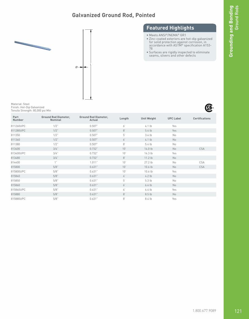
www.erico.pentair.com 1.800.677.9089 121
Grou
ndin
g an
d B
ondi
ngGr
ound
Rod
s
Galvanized Ground Rod, Pointed
• Meets ANSI®/NEMA® GR1• Zinc-coated exteriors are hot-dip galvanized
for solid protection against corrosion, in accordance with ASTM® specification A153-78
• Surfaces are rigidly inspected to eliminate seams, slivers and other defects
Featured Highlights
L Ø
Material: SteelFinish: Hot-Dip GalvanizedTensile Strength: 80,000 psi Min
Part Number
Ground Rod Diameter, Nominal
Ground Rod Diameter, Actual Length Unit Weight UPC Label Certifications
811260UPC 1/2” 0.507” 6’ 4.1 lb Yes811280UPC 1/2” 0.507” 8’ 5.4 lb Yes811350 1/2” 0.507” 5’ 3.4 lb No811360 1/2” 0.507” 6’ 4.1 lb No811380 1/2” 0.507” 8’ 5.4 lb No813400 3/4” 0.732” 10’ 14.0 lb No CSA813400UPC 3/4” 0.732” 10’ 14.3 lb Yes813480 3/4” 0.732” 8’ 11.2 lb No814400 1” 1.011” 10’ 27.2 lb No CSA815800 5/8” 0.631” 10’ 10.6 lb No CSA815800UPC 5/8” 0.631” 10’ 10.6 lb Yes815840 5/8” 0.631” 4’ 4.2 lb No815850 5/8” 0.631” 5’ 5.3 lb No815860 5/8” 0.631” 6’ 6.4 lb No815860UPC 5/8” 0.631” 6’ 6.4 lb Yes815880 5/8” 0.631” 8’ 8.5 lb No815880UPC 5/8” 0.631” 8’ 8.4 lb Yes
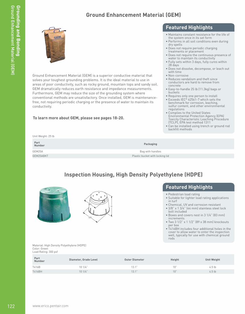
www.erico.pentair.com122
Grounding and Bonding
Ground Enhancement M
aterial (GEM)
Ground Enhancement Material (GEM)
• Maintains constant resistance for the life of the system once in its set form
• Performs in all soil conditions even during dry spells
• Does not require periodic charging treatments or placement
• Does not require the continuous presence of water to maintain its conductivity
• Fully sets within 3 days, fully cures within 28 days
• Does not dissolve, decompose, or leach out with time
• Non-corrosive• Reduces vandalism and theft since
conductors are hard to remove from concrete
• Easy-to-handle 25 lb (11.3kg) bags or buckets
• Requires only one person to install• Exceeds IEC® 62561-7 which sets the
benchmark for corrosion, leaching, sulfur content, and other environmental regulations
• Complies to the United States Environmental Protection Agency (EPA) Toxicity Characteristic Leaching Procedure (TCLP), EPA test method 1311
• Can be installed using trench or ground rod backfill methods
Featured Highlights
Ground Enhancement Material (GEM) is a superior conductive material that solves your toughest grounding problems. It is the ideal material to use in areas of poor conductivity, such as rocky ground, mountain tops and sandy soil. GEM dramatically reduces earth resistance and impedance measurements. Furthermore, GEM may reduce the size of the grounding system where conventional methods are unsatisfactory. Once installed, GEM is maintenance-free, not requiring periodic charging or the presence of water to maintain its conductivity.
Unit Weight: 25 lb Part Number Packaging
GEM25A Bag with handlesGEM25ABKT Plastic bucket with locking lid
Inspection Housing, High Density Polyethylene (HDPE)
• Pedestrian load rating• Suitable for lighter load rating applications
in turf• Chemical, UV and corrosion resistant• 3/8” x 1 3/4” (44 mm) stainless steel lock
bolt included• Boxes and covers nest in 3 1/4” (83 mm)
increments• Two 3 1/2” x 1 1/2” (89 x 38 mm) knockouts
per box• T416BH includes four additional holes in the
cover to allow water to enter the inspection well, typically for use with chemical ground rods
Featured Highlights
H
OD
DG
Material: High Density Polyethylene (HDPE)Color: GreenLoad Rating: 300 psf
Part Number Diameter, Grade Level Outer Diameter Height Unit Weight
T416B 10 1/4” 13.1” 10” 4.5 lbT416BH 10 1/4” 13.1” 10” 4.5 lb
To learn more about GEM, please see pages 18-20.
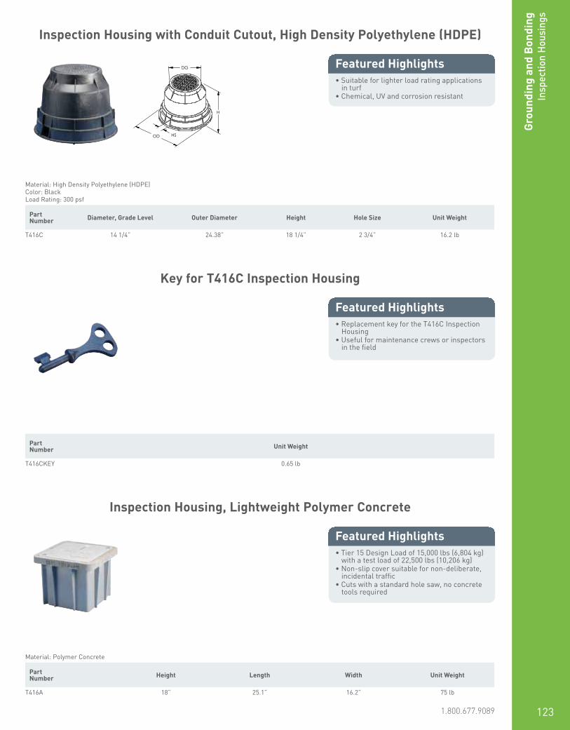
www.erico.pentair.com 1.800.677.9089 123
Grou
ndin
g an
d B
ondi
ngIn
spec
tion
Hou
sing
s
Inspection Housing with Conduit Cutout, High Density Polyethylene (HDPE)
• Suitable for lighter load rating applications in turf
• Chemical, UV and corrosion resistant
Featured Highlights
H
HS
DG
OD
Material: High Density Polyethylene (HDPE)Color: BlackLoad Rating: 300 psf
Part Number Diameter, Grade Level Outer Diameter Height Hole Size Unit Weight
T416C 14 1/4” 24.38” 18 1/4” 2 3/4” 16.2 lb
Key for T416C Inspection Housing
• Replacement key for the T416C Inspection Housing
• Useful for maintenance crews or inspectors in the field
Featured Highlights
Part Number Unit Weight
T416CKEY 0.65 lb
Inspection Housing, Lightweight Polymer Concrete
• Tier 15 Design Load of 15,000 lbs (6,804 kg) with a test load of 22,500 lbs (10,206 kg)
• Non-slip cover suitable for non-deliberate, incidental traffic
• Cuts with a standard hole saw, no concrete tools required
Featured Highlights
Material: Polymer Concrete Part Number Height Length Width Unit Weight
T416A 18” 25.1” 16.2” 75 lb

www.erico.pentair.com124
Grounding and Bonding
Inspection Housings
Part Number Height Length Width Unit Weight
T416D 12” 15.4” 15.4” 31 lbT416E 18” 15.4” 15.4” 35 lbT416F 23” 15.4” 15.4” 47 lb
Product specifications subject to change without notice.
Inspection Housing, High-Impact Polypropylene
• Offers a high level of protection for critical grounding terminations through the use of its lockable lid
• Easy-locking lid only opened with security key
• Ease of ground termination maintenance due to large working aperture
• Lightweight design allows easy handling, storage and transportation
• Suitable for both paving and hot tar applications
• UV-stabilized against degredation by sunlight
• Non-brittle to prevent cold weather damage• Base designed to accomodate Grounding
Busbar for Inspection Housing (545135)
Featured Highlights
H W L
Material: High-Impact Polypropylene Part Number Height Length Width Unit Weight
PIT03 8.5” 9.5” 8.2” 2.8 lb
Inspection Housing, Concrete
• Concrete design for higher load rating• Available with a central lifting hook• Flush-fitting lid with plain surface
minimizes slipping• Suitable for most grounding and lightning
protection installations• Base designed to accept 545140 Grounding
Busbar for Inspection Housings• Square shape
Featured Highlights
H
W
L
Material: ConcreteColor: Gray
Part Number Height Length Width Unit Weight
IP900C 6” 13” 13” 57.2 lb
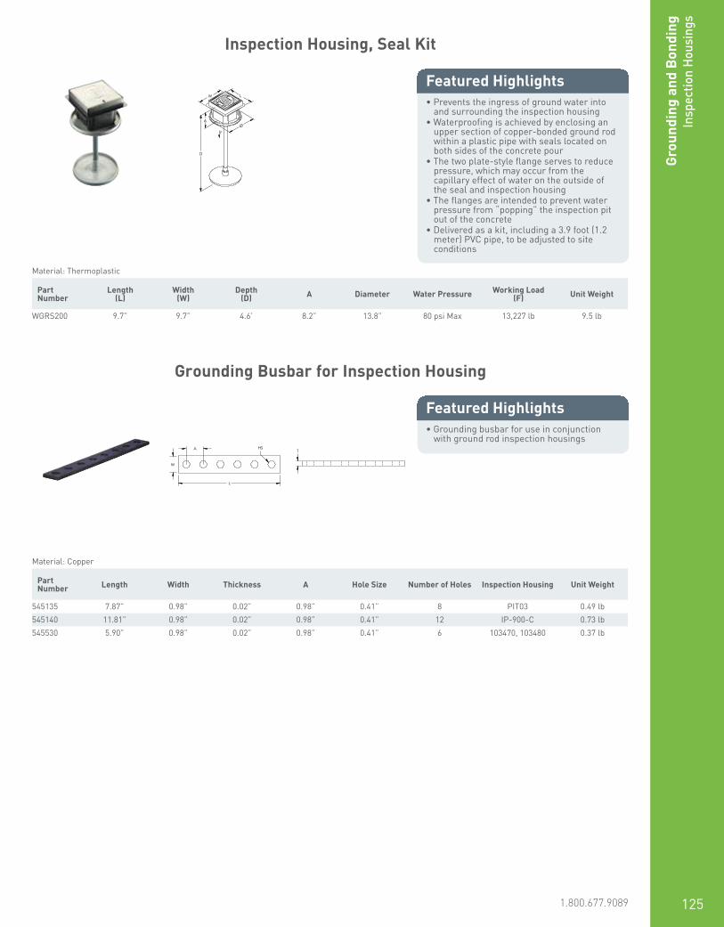
www.erico.pentair.com 1.800.677.9089 125
Grou
ndin
g an
d B
ondi
ngIn
spec
tion
Hou
sing
s
Inspection Housing, Seal Kit
• Prevents the ingress of ground water into and surrounding the inspection housing
• Waterproofing is achieved by enclosing an upper section of copper-bonded ground rod within a plastic pipe with seals located on both sides of the concrete pour
• The two plate-style flange serves to reduce pressure, which may occur from the capillary effect of water on the outside of the seal and inspection housing
• The flanges are intended to prevent water pressure from “popping” the inspection pit out of the concrete
• Delivered as a kit, including a 3.9 foot (1.2 meter) PVC pipe, to be adjusted to site conditions
Featured Highlights W
D
L
Ø A
F
Material: Thermoplastic Part Number
Length(L)
Width(W)
Depth(D) A Diameter Water Pressure Working Load
(F) Unit Weight
WGRS200 9.7” 9.7” 4.6’ 8.2” 13.8” 80 psi Max 13,227 lb 9.5 lb
Grounding Busbar for Inspection Housing
• Grounding busbar for use in conjunction with ground rod inspection housings
Featured Highlights
L
W
HS A T
Material: Copper Part Number Length Width Thickness A Hole Size Number of Holes Inspection Housing Unit Weight
545135 7.87” 0.98” 0.02” 0.98” 0.41” 8 PIT03 0.49 lb545140 11.81” 0.98” 0.02” 0.98” 0.41” 12 IP-900-C 0.73 lb545530 5.90” 0.98” 0.02” 0.98” 0.41” 6 103470, 103480 0.37 lb

www.erico.pentair.com126
Grounding and Bonding
Ground Mats and M
esh
Ground Mat
• Silver brazed joints (35% silver alloy brazing material) provide strength to resist separation during installation and bear the traffic of heavy vehicles
• Conductor spacing available in standard configurations
• Option to add center wire into the mat configuration is available
• Ground mats are laid flat onto pallets for shipping
Featured Highlights
Prefabricated ground mats, made of wire mesh, are ideal for systems designed for safety purposes to protect operators against “touch potentials” at manually operated disconnect switches.
L1
W1
W2
L2
Material: Copper, Copper-Bonded Steel Part Number MAT
Length 1 (L1) 96” Max
Width 1 (W1) 72” Max
Grid Spacing (L2 x W2) 2” x 2”4” x 4”’ 6” x 6”8” x 8”10” x 10”12” x 12”
Conductor Size #4 Solid Copper#6 Solid Copper#6 Copper-Clad Steel (30% or 40% Conductivity#8 Solid Copper#8 Copper-Clad Steel (30% or 40% Conductivity)
Center Wire Conductor Size 1/0 Solid or Stranded2/0 Solid or Stranded4/0 Solid or Stranded250 kcmil Stranded300 kcmil Stranded350 kcmil Stranded500 kcmil Stranded
Overhang Standard: Half Conductor Spacing + 2” (51 mm)With Center WireWith Overhanging Center Wire
W2 and L2 available in listed Grid Spacing only.

www.erico.pentair.com 1.800.677.9089 127
Grou
ndin
g an
d B
ondi
ngGr
ound
Mat
s an
d M
esh
Ground Mesh
• Prefabricated ground mesh wound into a roll format for shipping
• Silver brazed joints (35% silver alloy brazing material) provide strength to resist separation during installation and bear the traffic of heavy vehicles
• Conductor spacing in many rectangular configurations up to 24” x 48” (610 mm x 1219 mm) in 2” (51 mm) increments
• Normally supplied in sections with standard overhang for interconnecting half conductor spacing + 2” (51 mm)
Featured Highlights
Prefabricated ground mesh from ERICO is a convenient, efficient and economical means of improving grounding systems at facilities with high voltage installations and wherever large area grounds are required. Equipotential mesh reduces step potentials at power plants and substations, and effectively minimizes ground plane fluctuations at communications antenna sites. Wire mesh is also an excellent ground screen, reflector and electronic shield for large facilities.
L1
W1
W2
L2
Material: Copper, Copper-Bonded Steel Part Number MESH
Length 2 (L2) 2” – 24”
Width 1 (W1) 20’ Max
Width 2 (W2) 2” – 48”
Conductor Size #6 Solid Copper#6 Copper-Clad Steel (30% or 40% Conductivity)#8 Solid Copper#8 Copper-Clad Steel (30% or 40% Conductivity)#10 Solid Copper
Overhang Standard: Half Conductor Spacing + 2” (51 mm)NoneHalf Conductor Spacing
Unit Weight 500 lb Max
Net Weight (lbs) per 1,000 Square Feet
Conductor Spacing (W2 x L2) Copper-clad Steel Conductor (AWG) Solid Copper Conductor (AWG)
#6 #8 #10 #6 #8 #10
2” x 2” 888 lbs 558 lbs 351 lbs 974 lbs 609 lbs 383 lbs
4” x 4” 443 lbs 279 lbs 175 lbs 487 lbs 305 lbs 192 lbs
6” x 6” 295 lbs 186 lbs 117 lbs 325 lbs 203 lbs 128 lbs
8” x 8” 222 lbs 139 lbs 88 lbs 243 lbs 153 lbs 96 lbs
12” x 12” 148 lbs 93 lbs 59 lbs 163 lbs 102 lbs 64 lbs
24” x 24” 74 lbs 47 lbs 29 lbs 91 lbs 51 lbs 32 lbs
Add 75 lbs per roll for approximate shipping weight.
Length 1 (L1) is unlimited, up to 500 lbs. (227 kg) maximum. Length 2 (L2) and Width 2 (W2) are available in 2” (51 mm) increments only.
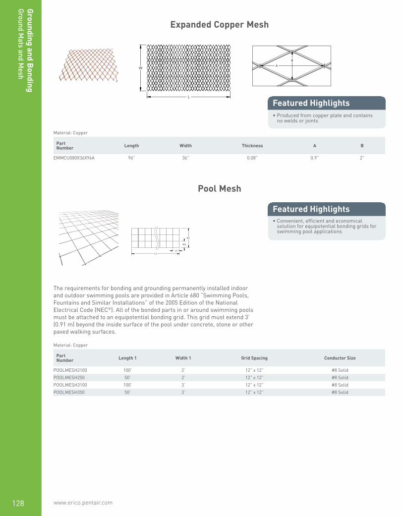
www.erico.pentair.com128
Grounding and Bonding
Ground Mats and M
esh
Expanded Copper Mesh
• Produced from copper plate and contains no welds or joints
Featured Highlights
W
L
A B
Material: Copper Part Number Length Width Thickness A B
EMMCU080X36X96A 96” 36” 0.08” 0.9” 2”
Pool Mesh
• Convenient, efficient and economical solution for equipotential bonding grids for swimming pool applications
Featured Highlights
The requirements for bonding and grounding permanently installed indoor and outdoor swimming pools are provided in Article 680 “Swimming Pools, Fountains and Similar Installations” of the 2005 Edition of the National Electrical Code (NEC®). All of the bonded parts in or around swimming pools must be attached to an equipotential bonding grid. This grid must extend 3’ (0.91 m) beyond the inside surface of the pool under concrete, stone or other paved walking surfaces.
L1
W1
W2
L2
Material: Copper Part Number Length 1 Width 1 Grid Spacing Conductor Size
POOLMESH2100 100’ 2’ 12” x 12” #8 SolidPOOLMESH250 50’ 2’ 12” x 12” #8 SolidPOOLMESH3100 100’ 3’ 12” x 12” #8 SolidPOOLMESH350 50’ 3’ 12” x 12” #8 Solid

www.erico.pentair.com 1.800.677.9089 129
Grou
ndin
g an
d B
ondi
ngSi
gnal
Ref
eren
ce G
rid
Signal Reference Grid
• Provides a low impedance equipotential plane to protect sensitive electronic equipment from transient noise
• Pre-engineered welded grid of 26 gauge copper strips reduces voltage differences between interconnected electronic equipment
• Welded connections do not deteriorate, corrode or loosen with time
• Can be easily field-welded to suit any size computer room
• Complies with IEEE® Standard 1100-1992
Featured Highlights
L1
W1
L2
W2
Material: Copper Part Number Length 1 Width 1 Grid Spacing Thickness Strip Width
SRGBD100 100’ 10’ 24” x 24” 0.016” 2”SRGBE100 100’ 12’ 24” x 24” 0.016” 2”SRGBG100 100’ 16’ 24” x 24” 0.016” 2”
Custom sizes available upon request. Contact your ERICO representative for more information.
Net Weight (lbs) per Standard Mat
Grid Spacing
2” x 2” 4” x 4” 6” x 6” 8” x 8” 12” x 12”
Conductor Size Standard Mat Size (square feet)
4’ x 4’ 4’ x 6’ 4’ x 4’ 4’ x 6’ 4’ x 4’ 4’ x 6’ 4’ x 4’ 4’ x 6’ 4’ x 4’ 4’ x 6’
#6 Copper-Clad Steel Wire
14.6 lbs 21.7 lbs 7.6 lbs 11.2 lbs 5.3 lbs 7.7 lbs 4.1 lbs 6 lbs 2.9 lbs 4.2 lbs
#8 Copper-Clad Steel Wire
9.2 lbs 13.7 lbs 4.8 lbs 7.1 lbs 3.3 lbs 4.9 lbs 2.6 lbs 3.8 lbs 1.9 lbs 2.7 lbs
Weights are for copper-clad steel wire. Add 10% for approximate weight of solid copper wire.
Mats are palletized for shipment. Add 50 lbs per pallet for gross weight. Maximum of 100 mats per pallet.

www.erico.pentair.com130
Grounding and Bonding
Ground Plates
Copper Ground Plate
• Provides a large surface area to dissipate current into the ground
• Available in a variety of sizes and pigtail configurations
Featured Highlights
GPE-C-E-A-H-024-1L-024-(T)
GPE Ground Plate Electrode
C Material A: Steel (HRS M1020)B: Stainless Steel (SS304)C: Copper (C11000)D: Galvanized Steel
D: Galvanized Steel
E Pigtail Connection Type C: Continuous (2 x “L J” ERICO CADWELD Connec-tion)E: End (“L J” ERICO CADWELD Connection Style)N: No Pigtail
A Plate Thickness Code (Stock Tolerance) A: 1/32” (Min. for Lightning – Cu)B: 1/16” (Min. for Power – Cu)C: 3/32”D: 1/8”E: 1/4” (Min. for Power – Stl.)F: 3/8”G: 1/2”H: 1/64” (26 Gauge)J: 3/16”
H Plate Width Code A: 1” · B: 2” · C: 3” · D: 4” · E: 5” · F: 6” · G: 9” · H: 12” · J: 18”K: 24” · L: 30” · M: 36” · N: 42” · P: 48” · Q: 17” · R: 10”
024 Plate Length Code (inches) (3 digits required)
1L* Pigtail Cable Type (ERICO Cable Code)
024* Pigtail Length (inches)
(T)* Tinned
Pigtail Connection
Continuous End None

www.erico.pentair.com 1.800.677.9089 131
Grou
ndin
g an
d B
ondi
ngGr
ound
Pla
tes
Material: Copper Part Number Width Length Pigtail Connection Pigtail Length Conductor Size Thickness
GPECCAM036 36” 36” None 1/32”GPECCAM0361H024 36” 36” Continuous 24” #6 Stranded 1/32”GPECCBJ0181T024 18” 18” Continuous 24” #2 Solid 1/16”GPECCBJ0181T060 18” 18” Continuous 60” #2 Solid 1/16”GPECCBJ181T108S 18” 18” Continuous 108” #2 Solid 1/16”GPECCDK0241L024 24” 24” Continuous 24” #4 Stranded 1/8”GPECCEK0242C036 24” 24” Continuous 36” 1/0 Stranded 1/4”GPECEAJ0181G024 18” 18” End 24” #6 Solid 1/32”GPECEAJ0241G024 18” 24” End 24” #6 Solid 1/32”GPECEAK0241G024 24” 24” End 24” #6 Solid 1/32”GPECEAK0241H024 24” 24” End 24” #6 Stranded 1/32”GPECEAK0242V024 24” 24” End 24” 250 kcmil Stranded 1/32”GPECEAM0361H024 36” 36” End 24” #6 Stranded 1/32”GPECEAM0362V012 36” 36” End 12” 250 kcmil Stranded 1/32”GPECEAP0481H024 48” 48” End 24” #6 Stranded 1/32”GPECEBH0121V024 12” 12” End 24” #2 Stranded 1/16”GPECEBH0241K024 12” 24” End 24” #4 Solid 1/16”GPECEBQ0171G120 17” 17” End 120” #6 Solid 1/16”GPECEDK0241L024 24” 24” End 24” #4 Stranded 1/8”GPECEDK0242Q036 24” 24” End 36” 4/0 Stranded 1/8”GPECEEK0241T024 24” 24” End 24” #2 Solid 1/4”GPECEEK0242Q008 24” 24” End 8” 4/0 Stranded 1/4”GPECEEK0242Q060 24” 24” End 60” 4/0 Stranded 1/4”GPECEEK0242Q120 24” 24” End 120” 4/0 Stranded 1/4”GPECEEK0242Q180 24” 24” End 180” 4/0 Stranded 1/4”GPECEEK0361T024 24” 36” End 24” #2 Solid 1/4”GPECNAJ018 18” 18” None 1/32”GPECNAK024 24” 24” None 1/32”GPECNBH012 12” 12” None 1/16”GPECNBH024 12” 24” None 1/16”GPECNDF006 6” 6” None 1/8”GPECNDH024 12” 24” None 1/8”GPECNEB024 2” 24” None 1/4”GPECNED004 4” 4” None 1/4”GPECNED012 4” 12” None 1/4”GPECNED014 4” 14” None 1/4”GPECNED096 4” 96” None 1/4”GPECNEG024 9” 24” None 1/4”GPECNEH016 12” 16” None 1/4”GPECNEK024 24” 24” None 1/4”GPECNEM040 36” 40” None 1/4”GPECNEN040 42” 40” None 1/4”GPECNFH033 12” 33” None 3/8”GPECNFK024 24” 24” None 3/8”GPECNGF012 6” 12” None 1/2”GPECNGK024 24” 24” None 1/2”GPECNHM096 36” 96” None 1/64”
Finish: TinnedGPECCDM0361T10T 36” 36” Continuous 10” #2 Solid 1/8”GPECEJK0361T24T 24” 36” End 24” #2 Solid 3/16”GPECNDK024T 24” 24” None 1/8”GPECNDM036T 36” 36” None 1/8”

www.erico.pentair.com132
Grounding and Bonding
Ground Plates
Copper Ground Plate with Bent Corners
• Used to ground utility poles• The corners of the ground plate are nailed
into the base of the pole
Featured Highlights
L
HS
W
Material: Copper Part Number Length Width Thickness Hole Size Conductor Size Pigtail Included Pigtail Length
Finish: Bare — Type: Ground Plate, No HolesGPECEHX1 17” 17” 0.064” #6 Solid Yes 12’GPECEHX3 17” 17” 0.064” #2 Stranded Yes 12’
Finish: Tinned — Type: Ground Plate With HolesGPECEHX1T 17” 17” 0.064” 1/2” #6 Solid Yes 12’
The pigtail for GPECEHX1T is tinned, but the plate itself is bare copper.
Copper Ground Plate with Cable Attachments
• Bonding plates provide mechanical attachment points to ground plate
• Listed to UL® 96
Featured Highlights
L
W
T
T
Material: Copper Part Number Width Length Thickness
Number of Cable Attachments: 1LPC753 12” 24” 20 GALPC754 18” 18” 20 GALPC755 36” 36” 20 GA
Number of Cable Attachments: 2LPC750 12” 24” 20 GALPC751 18” 18” 20 GALPC752 36” 36” 20 GALPC756 24” 24” 20 GA

www.erico.pentair.com 1.800.677.9089 133
Grou
ndin
g an
d B
ondi
ngGr
ound
Pla
tes
Copper Utility Ground Plate
• Provides a large surface area to dissipate current into the ground
• Wrap around the bottom of a utility pole to install
Featured Highlights
L
W
Part Number Connector Length Width Thickness Standard Packaging
Quantity
UGP719 SRGC46 19 1/4” 7 1/2” 1/16” 1 pcUGP719BP5 SRGC46 19 1/4” 7 1/2” 1/16” 5 pcUGP719SBP5 ESB2 Split Bolt 19 1/4” 7 1/2” 1/16” 5 pcUGP738 SRGC46 38 1/2” 7 1/2” 1/16” 1 pcUGP738P10 SRGC46 38 1/2” 7 1/2” 1/16” 10 pcUGP738P5 SRGC46 38 1/2” 7 1/2” 1/16” 5 pcUGP738SBP5 ESB2 Split Bolt 38 1/2” 7 1/2” 1/16” 5 pc
Copper Utility Pole Bottom Plate
• Integrated connector provides a convenient method for terminating the grounding conductor
• Quick and easy installation• Cost-effective ground electrode solution• Manufactured of corrosion-resistant
electrolytic copper• Construction meets the requirements of the
NESC®
• Fix cable and nail to base before raising pole
Featured Highlights
ø
Material: Copper Part Number Connector Conductor Size Diameter Thickness
EGP100 Lug #14 Solid - #4 Stranded, 2.5 mm² Stranded - 16 mm² Stranded 7 1/2” 0.025”EGP100HL ERICO HAMMERLOCK #14 Solid - #4 Stranded, 2.5 mm² Stranded - 16 mm² Stranded 7 1/2” 0.025”

www.erico.pentair.com134
Grounding and Bonding
Ground Plates
Steel Ground Plate
• Provides a large surface area to dissipate current into the ground
• Includes a welded steel rod pigtail
Featured Highlights
W
L1
L2
Ø
Material: Steel Part Number Connector Length 1 Length 2 Width Thickness Diameter Certifications
Finish: ElectrogalvanizedEGGP None 16” 2” 10” 1/4” 5/8” C-CSA-USEGGPC HDC58 16” 2” 10” 1/4” 5/8” C-CSA-US
Finish: PlainEBGP None 16” 2” 10” 1/4” 5/8”
B162 Earthpoint, Two Stud
• Long-lasting design• Low ground resistance and impedance• Superior electrical conductivity and
resistance to corrosion• Electrically and mechanically robust and
reliable• Easy to install as a Prefabricated
Earthbridge once ERICO CADWELD welded to a piece of conductor
Featured Highlights
H
W2
W1
D
TS
Material: Brass Part Number Width 1 Width 2 Depth Height Diameter Thread Size
B1622Q 1 3/4” 3 1/4” 1 5/8” 3” 0.53” 1/2 UNC
Assemblies require conductors and ERICO CADWELD connections, which must be ordered separately.

www.erico.pentair.com 1.800.677.9089 135
Grou
ndin
g an
d B
ondi
ngGr
ound
Poi
nts
for
Conc
rete
B161/B164 Earthpoint, Four Stud
• Long-lasting design• Low ground resistance and impedance• Superior electrical conductivity and
resistance to corrosion• Electrically and mechanically robust and
reliable• Easy to install as a Prefabricated
Earthbridge once ERICO CADWELD welded to a piece of conductor
Featured Highlights
H D2
W2
D1
W1
TS
Material: Brass Part Number Width 1 Width 2 Depth 1 Depth 2 Height Diameter Thread Size
B1612Q 1 1/4” 2 1/2” 1” 2 1/4” 3” 0.530” 3/8 UNCB1613Q 1 1/4” 2 1/2” 1” 2 1/4” 3” 0.825” 3/8 UNCB1642Q 1 3/4” 3 1/4” 1 3/4” 3 1/4” 3” 0.530” 1/2 UNCB1643Q 1 3/4” 3 1/4” 1 3/4” 3 1/4” 3” 0.825” 1/2 UNC
Assemblies require conductors and ERICO CADWELD connections, which must be ordered separately.
Ground Point
• Cast grounding plate for equipment, machinery, or structure grounding points
• May be installed flush in concrete floor or wall
• Cable connection under bolt tension
Featured Highlights W
TS
D
A
Material: Brass Part Number Conductor Size, UL Thread Size Depth Width A Unit Weight
LPC682 Class 1 - Class 2 (4/0 Max) 1/2 UNC 3 1/4” 3 1/4” 1 3/4” 1.535 lb

www.erico.pentair.com136
Grounding and Bonding
Ground Points for Concrete
Rebar Bonding Kit, Single Connection
• Kit includes Rebar Bonding Plate, Rebar Bonding Clamp and conductor
• Provides ground system connection points in concrete structures
• Used for equipment, machinery and structure grounding
Featured Highlights
A
A
TS
Material: Brass, Copper Part Number Conductor Type Cable Length Thread Size A Unit Weight
LPC46740X1 LPC404 3’ 1/2 UNC 4” 3.218 lbLPC467X1 LPC401 3’ 1/2 UNC 4” 2.400 lb
Rebar Bonding Kit, Dual Connection
• Kit includes Rebar Bonding Plate, two Rebar Bonding Clamps and two conductors
• Provides ground system connection points in concrete structures
• Used for equipment, machinery and structure grounding
Featured Highlights
A
A
TS
Material: Brass, Copper Part Number Conductor Type Cable Length Thread Size A Unit Weight
LPC46740X2 LPC404 3’ 1/2 UNC 4” 5.792 lbLPC467X2 LPC401 3’ 1/2 UNC 4” 4.154 lb
Cable Length represents the length of a single conductor.
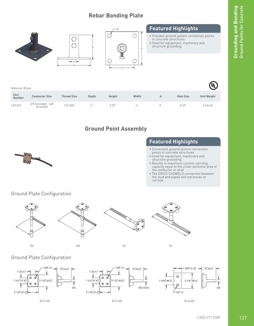
www.erico.pentair.com 1.800.677.9089 137
Grou
ndin
g an
d B
ondi
ngGr
ound
Poi
nts
for
Conc
rete
Rebar Bonding Plate
• Provides ground system connection points in concrete structures
• Used for equipment, machinery and structure grounding
Featured Highlights
W
H
TS
HS
D
A
Material: Brass Part Number Conductor Size Thread Size Depth Height Width A Hole Size Unit Weight
LPC467 2/0 Stranded - 4/0 Stranded 1/2 UNC 4” 2.92” 4” 3” 0.45” 0.644 lb
Ground Point Assembly
• Convenient ground system connection points in concrete structures
• Used for equipment, machinery and structure grounding
• Results in maximum current-carrying capacity equal to the cross-sectional area of the conductor or stud
• The ERICO CADWELD connection between the stud and pigtail will not loosen or corrode
Featured Highlights
Ground Plate Configuration
Ground Plate Configuration
RA
B1612Q B1613Q B1622Q
RB SS TA

www.erico.pentair.com138
Grounding and Bonding
Ground Points for Concrete
B530-A-2Q-72
B530 Ground Plate Configuration B530 = RAB531 = RBB532 = SSB533 = TA
A Ground Plate Part Number A = B1612QB = B1613QC = B1622QD = B1642QE = B1643Q
2Q Cable Code 1G = #6 Solid1L = #4 Stranded1V = #2 Stranded
2C = 1/0 Stranded2G = 2/0 Stranded2Q = 4/0 Stranded
2V = 250 MCM Stranded3D = 350 MCM Stranded3Q = 500 MCM Stranded
72 Cable Length (inches)
Material: Copper Alloy Part Number Ground Plate Configuration Ground Plate Part Number Conductor Size Cable Length
B530A1L12 RA B1612Q #4 Stranded 12”B530A1V12 RA B1612Q #2 Stranded 12”B530A2Q48 RA B1612Q 4/0 Stranded 48”B530A2Q72 RA B1612Q 4/0 Stranded 72”B530B2G24 RA B1613Q 2/0 Stranded 24”B530C1L048 RA B1622Q #4 Stranded 48”B530C2C24 RA B1622Q 1/0 Stranded 24”B530C2G48 RA B1622Q 2/0 Stranded 48”B530C2Q36 RA B1622Q 4/0 Stranded 36”B530C2Q48 RA B1622Q 4/0 Stranded 48”B530C2Q96 RA B1622Q 4/0 Stranded 96”B530D2C48 RA B1642Q 1/0 Stranded 48”B530D2G18 RA B1642Q 2/0 Stranded 18”B530D2G180 RA B1642Q 2/0 Stranded 180”B530D2G24 RA B1642Q 2/0 Stranded 24”B530D2G48 RA B1642Q 2/0 Stranded 48”B530D2Q12 RA B1642Q 4/0 Stranded 12”B530D2Q120 RA B1642Q 4/0 Stranded 120”B530D2Q144 RA B1642Q 4/0 Stranded 144”B530D2Q180 RA B1642Q 4/0 Stranded 180”B530D2Q24 RA B1642Q 4/0 Stranded 24”B530D2Q32 RA B1642Q 4/0 Stranded 32”B530D2Q36 RA B1642Q 4/0 Stranded 36”B530D2Q48 RA B1642Q 4/0 Stranded 48”B530D2Q72 RA B1642Q 4/0 Stranded 72”B530D2Q96 RA B1642Q 4/0 Stranded 96”B531A2Q36 RB B1612Q 4/0 Stranded 36”B531D2G24 RB B1642Q 2/0 Stranded 24”
B1642Q B1643Q

www.erico.pentair.com 1.800.677.9089 139
Grou
ndin
g an
d B
ondi
ngAi
rcra
ft an
d St
atic
Gro
undi
ng
Part Number Ground Plate Configuration Ground Plate Part Number Conductor Size Cable Length
B531D2Q12 RB B1642Q 4/0 Stranded 12”B531D2Q120 RB B1642Q 4/0 Stranded 120”B531D2Q144 RB B1642Q 4/0 Stranded 144”B531D2Q24 RB B1642Q 4/0 Stranded 24”B531D2Q48 RB B1642Q 4/0 Stranded 48”B531D2Q6 RB B1642Q 4/0 Stranded 6”B531D2Q72 RB B1642Q 4/0 Stranded 72”B531D2Q96 RB B1642Q 4/0 Stranded 96”B532A2Q48 SS B1612Q 4/0 Stranded 48”B532C2G24 SS B1622Q 2/0 Stranded 24”B532C2G60 SS B1622Q 2/0 Stranded 60”B532C2Q240 SS B1622Q 4/0 Stranded 240”B532C2Q48 SS B1622Q 4/0 Stranded 48”B532C2V48 SS B1622Q 250 kcmil Stranded 48”B532C3Q48 SS B1622Q 500 kcmil Stranded 48”B532D1L48 SS B1642Q #4 Stranded 48”B532D1V36 SS B1642Q #2 Stranded 36”B532D2C24 SS B1642Q 1/0 Stranded 24”B532D2C36 SS B1642Q 1/0 Stranded 36”B532D2G12 SS B1642Q 2/0 Stranded 12”B532D2G48 SS B1642Q 2/0 Stranded 48”B532D2Q36 SS B1642Q 4/0 Stranded 36”B532D2Q40 SS B1642Q 4/0 Stranded 40”B532D2Q48 SS B1642Q 4/0 Stranded 48”B532D2Q50 SS B1642Q 4/0 Stranded 50”B532D2Q72 SS B1642Q 4/0 Stranded 72”B532E3D96 SS B1643Q 350 kcmil Stranded 96”B532E3Q48 SS B1643Q 500 kcmil Stranded 48”B532E3Q96 SS B1643Q 500 kcmil Stranded 96”B533A2G48 TA B1612Q 2/0 Stranded 48”B533A2Q24 TA B1612Q 4/0 Stranded 24”B533C2Q48 TA B1622Q 4/0 Stranded 48”B533D2Q12 TA B1642Q 4/0 Stranded 12”B533D2Q24 TA B1642Q 4/0 Stranded 24”B533D2Q48 TA B1642Q 4/0 Stranded 48”
Custom lengths available. Please contact ERICO for details.
Aircraft Grounding Receptacle with Bar Attachment Point
• Castings for use in static grounding systems of refueling areas
• Suitable as a combination tie down and static ground point
• Easily connected to grounding system conductor and/or ground rods
• Designed for simple installation with flush paved surfaces
• Compatible with ERICO CADWELD connections
Featured Highlights
D
Ø1 Ø2
AP
Material: Phosphor Bronze Part Number Diameter 1 Diameter 2 Depth Attachment Point Pipe Size Connection Type
B166 3 7/8” 3 5/8” 6 1/4” 3/4” Diameter Bar 1/2” RA, RBB167 4 3/4” 4 13/32” 7 1/4” 1 1/2” Diameter Bar 1/2” RA, RB

www.erico.pentair.com140
Grounding and Bonding
Aircraft and Static Grounding
Aircraft Grounding Receptacle with Ball Stud
• Castings for use in static grounding systems of refueling areas
• Easily connected to grounding system conductor and/or ground rods
• Designed for simple installation with flush paved surfaces
• Compatible with ERICO CADWELD connections
Featured Highlights
D
Ø1 Ø2
AP
Material: Phosphor Bronze Part Number Diameter 1 Diameter 2 Depth Attachment Point Pipe Size Connection Type
B165 2 3/4” 2 3/16” 4 1/2” Permanent 5/8” Ball Stud 1/2” RA, RBB165R 2 3/4” 2 3/16” 4 1/2” Removable 5/8” Ball Stud 1/2” RA, RB
Aircraft Grounding Receptacle Replacement Ball Stud
• Replacement ball stud for B165R Aircraft Grounding Receptacle
Featured Highlights
Material: Phosphor Bronze Part Number
B165RS
Aircraft Grounding Receptacle Replacement Cover
• Replacement covers available for Aircraft Grounding Receptacles
• Includes cover only, without chain or spring clip
Featured Highlights
Ø
Material: Phosphor Bronze Part Number For Use With Diameter
B165B B165 and B165R 2 3/16”

www.erico.pentair.com 1.800.677.9089 141
Grou
ndin
g an
d B
ondi
ngAi
rcra
ft an
d St
atic
Gro
undi
ng
Part Number For Use With Diameter
B166B B166 3 5/8”B167B B167 4 13/32”
Aircraft Grounding Receptacle for Sectional Ground Rods
• Castings for use in static grounding systems of refueling areas
• Designed for simple installation with flush paved surfaces
• Standard pin connection• Chain-retained cover plate• Couple directly to 3/4” (nominal) sectional
or extension rod• LPC681 includes spring clip to secure the
cover plate• Listed to UL® 96
Featured Highlights
H
Ø
Material: Bronze Part Number Diameter Height Attachment Point Spring Clip Included
LPC680 2 3/4” 3 1/2” Permanent 3/4” Ball Stud NoLPC681 2 3/4” 3 1/2” Permanent 3/4” Ball Stud Yes
Aircraft Grounding Tie Down
• Used as an attachment point for static grounding
Featured Highlights
L B
A
TS
Ø
Material: Copper-Bonded Steel, Bronze Part Number Diameter Length Thread Size A B
663400 2” 10’ 3/4 UNC 5” 1”

www.erico.pentair.com142
Grounding and Bonding
Aircraft and Static Grounding
Aircraft Grounding Tie Down Mold
• Plastic mold for making depression in concrete pour around loop in Aircraft Grounding Tie Down
Featured Highlights
L
D
W
Material: High-Impact Polystyrene Part Number Length Width Depth
DM5834 6” 3” 2.9”
Aircraft Grounding Clamp
• Fits ground rods up to 3/4” nominal and ERICO Aircraft Grounding Receptacles B165 and B166
• Cast aluminum construction with plated steel jaws
• Aviation industry standard for bonding and grounding aircraft and refueling vehicles
• Ideal for attaching to landing gear, posts, ground balls, ground rods and other curved unpainted surfaces
• Complies with Mil Spec M83413/7-1
Featured Highlights
Material: Aluminum, Steel Part Number Jaw Opening Throat Depth Harness Included
B2617A 3/4” Max 3/4” No

www.erico.pentair.com 1.800.677.9089 143
Grou
ndin
g an
d B
ondi
ngAi
rcra
ft an
d St
atic
Gro
undi
ng
Static Grounding Clamp For Drums
• Designed specifically for grounding or bonding small containers, drums, totes, machinery or personnel in areas containing flammable liquids or dust
• Plier-type clamp has a die cast aluminum body with two stainless steel points and a hefty 55 pound (25 kg) spring compression
• Design allows the clamp to penetrate multiple layers of paint or corrosion build-up so that proper contact is made to bare metal
Featured Highlights
Material: Aluminum, Stainless Steel 416 (EN 1.4005) Part Number Jaw Opening Throat Depth Harness Included
B2610A 1” Max 1” No
FM is a registered certification mark of FM Approvals LLC, LTD.
Static Grounding Cable Reel, Bare Cable
• Includes a stop at the end of the retractable cable
• Typically used with B2610A Static Grounding Clamp For Drums (sold separately)
Featured Highlights
Material: SteelFinish: Electrogalvanized
Part Number Product Diameter Length
B2618A Cable for grounding flammable drums and totes 3/32” 20’B2618B Cable for grounding tanker trucks and rail cars 3/32” 50’
Containers with flammable liquid should remain closed until bonding and grounding is complete, because an initial spark may occur during the connection of grounding equipment which could ignite vapors or gases.

www.erico.pentair.com144

www.erico.pentair.com 1.800.677.9089
GROUNDINGBUSBARS
145

www.erico.pentair.com146
Grounding Busbar - Electrical Busbar
• Provides a convenient, single-point grounding and bonding location
• Conductors are welded to the bar using a ERICO CADWELD exothermic connection or are mechanically fastened by using lugs
• Custom bars can be designed and manufacturerd to customer specifications
Featured Highlights
Busbars
Grounding Busbars and Supports
Thickness18 = 1/8” 58 = 5/8” 12 = 1/2”38 = 3/8” 14 = 1/4” 34 = 3/4”
Pig Tail Length Ft. (Empty if none)
A = 1 E = 5 J = 9 N = 16 S = 24 W = 32B = 2 F = 6 K = 10 O = 17 T = 25 X = 34C = 3 G = 7 L = 11 P = 18 U = 26 Y = 36D = 4 H = 8 M = 12 Q = 19 V = 27 Z = 38
ConfigurationA = Insul & Brkt C = None (Bar only)B = Brkt only D = Insul only
Tin Plating (Empty if none)
T = Tinned
ERICO Cable Code (Empty if none)
1K = #4 Sol Tin 2C = 1/0 2V = 250 KCM1T = #2 Sol Tin SG = 2/0 3D = 350 KCM 2L = 3/0 3Q = 500 KCM 2Q = 4/0 4L = 750 KCM
Hole Pattern
Length (rounded to the nearest inch, up to 96 inch max.)
ERICO Ground Bar Designaton
Width1 = 1” 4 = 4” 7 = 7”2 = 2” 5 = 5” 8 = 8” 3 = 3” 6 = 6” 9 = 9”
4 4E G B A 1 1 2 C C

www.erico.pentair.com 1.800.677.9089 147
CC
BF
EC
BB
DD
CCSKY
NN
CA
EE
BD
DG
CF
AA
CB
FF
BE
EB
CIGBE
Bus
bars
Grou
ndin
g Bu
sbar
s an
d Su
ppor
ts

www.erico.pentair.com148
GE
KK
HIG
SS
PP
GG
LL
JE
HH
MM
JJ
RR
Busbars
Grounding Busbars and Supports

www.erico.pentair.com 1.800.677.9089 149
Global Part Number
Hole Pattern
Mounting Hole Size Length Width Thickness Tin Plating Pigtail Included
EGBA14112EE EE 0.438” 12” 1” 1/4” No No
EGBA14212BB BB 0.438” 12” 2” 1/4” No No
EGBA14212EE EE 0.438” 12” 2” 1/4” No No
EGBA14212HH HH 0.438” 12” 2” 1/4” No No
EGBA14212NN NN 0.438” 12” 2” 1/4” No No
EGBA14212TES TES 0.438” 12” 2” 1/4” No No
EGBA14215JJ JJ 0.438” 15” 2” 1/4” No No
EGBA14215TES TES 0.438” 15” 2” 1/4” No No
EGBA14224NN NN 0.438” 24” 2” 1/4” No No
EGBA14406CC CC 0.438” 6” 4” 1/4” No No
EGBA14410FF FF 0.438” 10” 4” 1/4” No No
EGBA14412AA AA 0.438” 12” 4” 1/4” No No
EGBA14412BB BB 0.438” 12” 4” 1/4” No No
EGBA14412CC CC 0.438” 12” 4” 1/4” No No
EGBA14412GG GG 0.438” 12” 4” 1/4” No No
EGBA14412LL LL 0.438” 12” 4” 1/4” No No
EGBA14412MM MM 0.438” 12” 4” 1/4” No No
EGBA14412NN NN 0.438” 12” 4” 1/4” No No
EGBA14420CC CC 0.438” 20” 4” 1/4” No No
EGBA14420CCT CC 0.438” 20” 4” 1/4” Yes No
EGBA14420NN NN 0.438” 20” 4” 1/4” No No
EGBA14424CC CC 0.438” 24” 4” 1/4” No No
EGBA14424GG GG 0.438” 24” 4” 1/4” No No
EGBA14424LL LL 0.438” 24” 4” 1/4” No No
EGBA14424MM MM 0.438” 24” 4” 1/4” No No
EGBA14424NN NN 0.438” 24” 4” 1/4” No No
EGBA14436CC CC 0.438” 36” 4” 1/4” No No
Bus
bars
Grou
ndin
g Bu
sbar
s an
d Su
ppor
ts
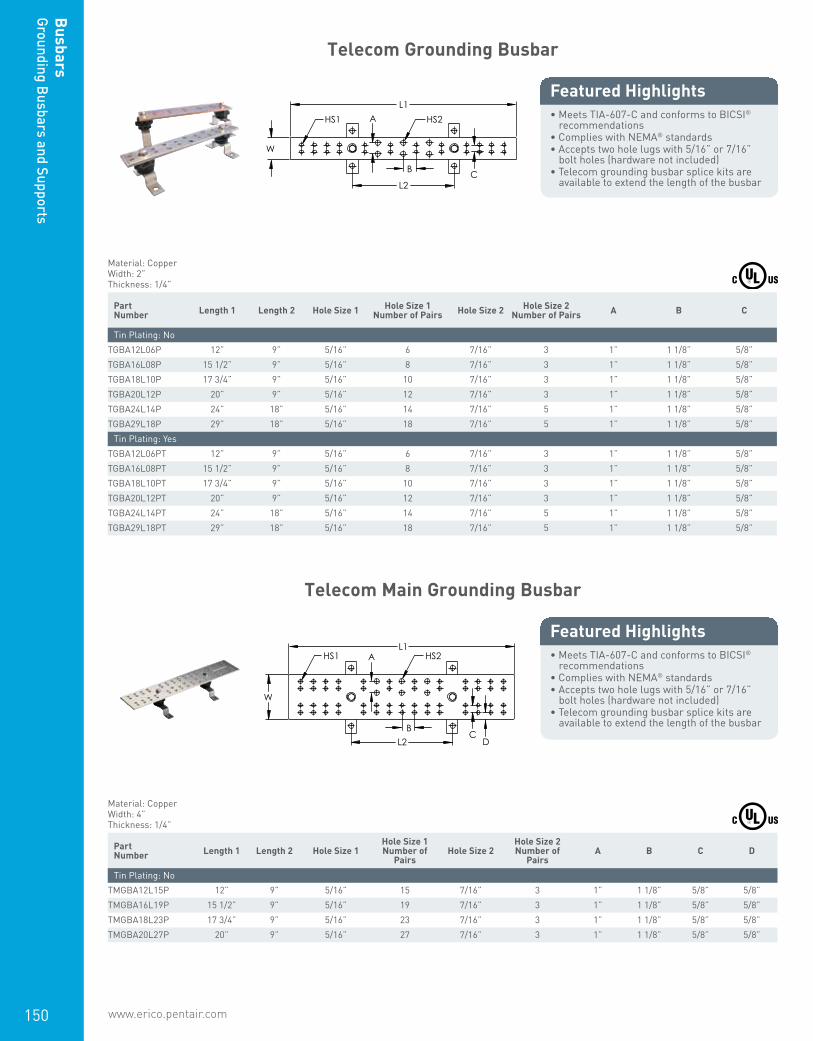
www.erico.pentair.com 1.800.677.9089150
Busbars
Grounding Busbars and Supports
Telecom Grounding Busbar
• Meets TIA-607-C and conforms to BICSI® recommendations
• Complies with NEMA® standards• Accepts two hole lugs with 5/16” or 7/16”
bolt holes (hardware not included)• Telecom grounding busbar splice kits are
available to extend the length of the busbar
Featured Highlights L1
W
L2
A HS1 HS2
C B
Material: CopperWidth: 2”Thickness: 1/4”
Part Number Length 1 Length 2 Hole Size 1 Hole Size 1
Number of Pairs Hole Size 2 Hole Size 2 Number of Pairs A B C
Tin Plating: NoTGBA12L06P 12” 9” 5/16” 6 7/16” 3 1” 1 1/8” 5/8”TGBA16L08P 15 1/2” 9” 5/16” 8 7/16” 3 1” 1 1/8” 5/8”TGBA18L10P 17 3/4” 9” 5/16” 10 7/16” 3 1” 1 1/8” 5/8”TGBA20L12P 20” 9” 5/16” 12 7/16” 3 1” 1 1/8” 5/8”TGBA24L14P 24” 18” 5/16” 14 7/16” 5 1” 1 1/8” 5/8”TGBA29L18P 29” 18” 5/16” 18 7/16” 5 1” 1 1/8” 5/8”
Tin Plating: YesTGBA12L06PT 12” 9” 5/16” 6 7/16” 3 1” 1 1/8” 5/8”TGBA16L08PT 15 1/2” 9” 5/16” 8 7/16” 3 1” 1 1/8” 5/8”TGBA18L10PT 17 3/4” 9” 5/16” 10 7/16” 3 1” 1 1/8” 5/8”TGBA20L12PT 20” 9” 5/16” 12 7/16” 3 1” 1 1/8” 5/8”TGBA24L14PT 24” 18” 5/16” 14 7/16” 5 1” 1 1/8” 5/8”TGBA29L18PT 29” 18” 5/16” 18 7/16” 5 1” 1 1/8” 5/8”
Telecom Main Grounding Busbar
• Meets TIA-607-C and conforms to BICSI® recommendations
• Complies with NEMA® standards• Accepts two hole lugs with 5/16” or 7/16”
bolt holes (hardware not included)• Telecom grounding busbar splice kits are
available to extend the length of the busbar
Featured Highlights L1
W
L2 B
A
C D
HS1 HS2
Material: CopperWidth: 4”Thickness: 1/4”
Part Number Length 1 Length 2 Hole Size 1
Hole Size 1 Number of
PairsHole Size 2
Hole Size 2 Number of
PairsA B C D
Tin Plating: NoTMGBA12L15P 12” 9” 5/16” 15 7/16” 3 1” 1 1/8” 5/8” 5/8”TMGBA16L19P 15 1/2” 9” 5/16” 19 7/16” 3 1” 1 1/8” 5/8” 5/8”TMGBA18L23P 17 3/4” 9” 5/16” 23 7/16” 3 1” 1 1/8” 5/8” 5/8”TMGBA20L27P 20” 9” 5/16” 27 7/16” 3 1” 1 1/8” 5/8” 5/8”
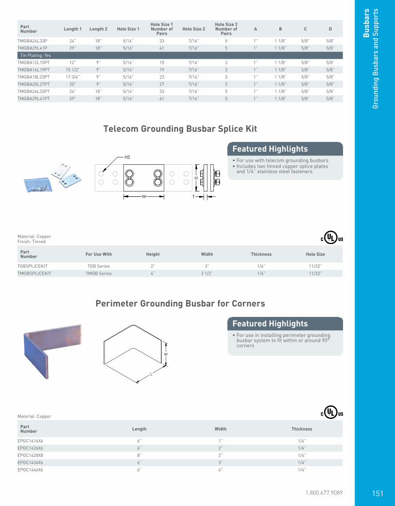
www.erico.pentair.com 1.800.677.9089 151
Bus
bars
Grou
ndin
g Bu
sbar
s an
d Su
ppor
ts
Part Number Length 1 Length 2 Hole Size 1
Hole Size 1 Number of
PairsHole Size 2
Hole Size 2 Number of
PairsA B C D
TMGBA24L33P 24” 18” 5/16” 33 7/16” 5 1” 1 1/8” 5/8” 5/8”TMGBA29L41P 29” 18” 5/16” 41 7/16” 5 1” 1 1/8” 5/8” 5/8”
Tin Plating: YesTMGBA12L15PT 12” 9” 5/16” 15 7/16” 3 1” 1 1/8” 5/8” 5/8”TMGBA16L19PT 15 1/2” 9” 5/16” 19 7/16” 3 1” 1 1/8” 5/8” 5/8”TMGBA18L23PT 17 3/4” 9” 5/16” 23 7/16” 3 1” 1 1/8” 5/8” 5/8”TMGBA20L27PT 20” 9” 5/16” 27 7/16” 3 1” 1 1/8” 5/8” 5/8”TMGBA24L33PT 24” 18” 5/16” 33 7/16” 5 1” 1 1/8” 5/8” 5/8”TMGBA29L41PT 29” 18” 5/16” 41 7/16” 5 1” 1 1/8” 5/8” 5/8”
Telecom Grounding Busbar Splice Kit
• For use with telecom grounding busbars• Includes two tinned copper splice plates
and 1/4” stainless steel fasteners
Featured Highlights
W
H
T
HS
Material: CopperFinish: Tinned
Part Number For Use With Height Width Thickness Hole Size
TGBSPLICEKIT TGB Series 2” 3” 1/4” 11/32”TMGBSPLICEKIT TMGB Series 4” 3 1/2” 1/4” 11/32”
Perimeter Grounding Busbar for Corners
• For use in installing perimeter grounding busbar system to fit within or around 90° corners
Featured Highlights
L
W
Material: Copper Part Number Length Width Thickness
EPGC1416X6 6” 1” 1/4”EPGC1426X6 6” 2” 1/4”EPGC1428X8 8” 2” 1/4”EPGC1436X6 6” 3” 1/4”EPGC1446X6 6” 4” 1/4”
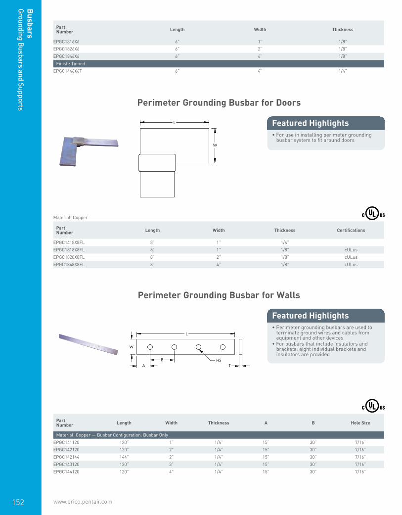
www.erico.pentair.com152
Busbars
Grounding Busbars and Supports
Part Number Length Width Thickness
EPGC1816X6 6” 1” 1/8”EPGC1826X6 6” 2” 1/8”EPGC1846X6 6” 4” 1/8”
Finish: TinnedEPGC1446X6T 6” 4” 1/4”
Perimeter Grounding Busbar for Doors
• For use in installing perimeter grounding busbar system to fit around doors
Featured Highlights L
W
Material: Copper Part Number Length Width Thickness Certifications
EPGC1418X8FL 8” 1” 1/4”EPGC1818X8FL 8” 1” 1/8” cULusEPGC1828X8FL 8” 2” 1/8” cULusEPGC1848X8FL 8” 4” 1/8” cULus
Perimeter Grounding Busbar for Walls
• Perimeter grounding busbars are used to terminate ground wires and cables from equipment and other devices
• For busbars that include insulators and brackets, eight individual brackets and insulators are provided
Featured Highlights
L
W
HS A
B T
Part Number Length Width Thickness A B Hole Size
Material: Copper — Busbar Configuration: Busbar OnlyEPGC141120 120” 1” 1/4” 15” 30” 7/16”EPGC142120 120” 2” 1/4” 15” 30” 7/16”EPGC142144 144” 2” 1/4” 15” 30” 7/16”EPGC143120 120” 3” 1/4” 15” 30” 7/16”EPGC144120 120” 4” 1/4” 15” 30” 7/16”
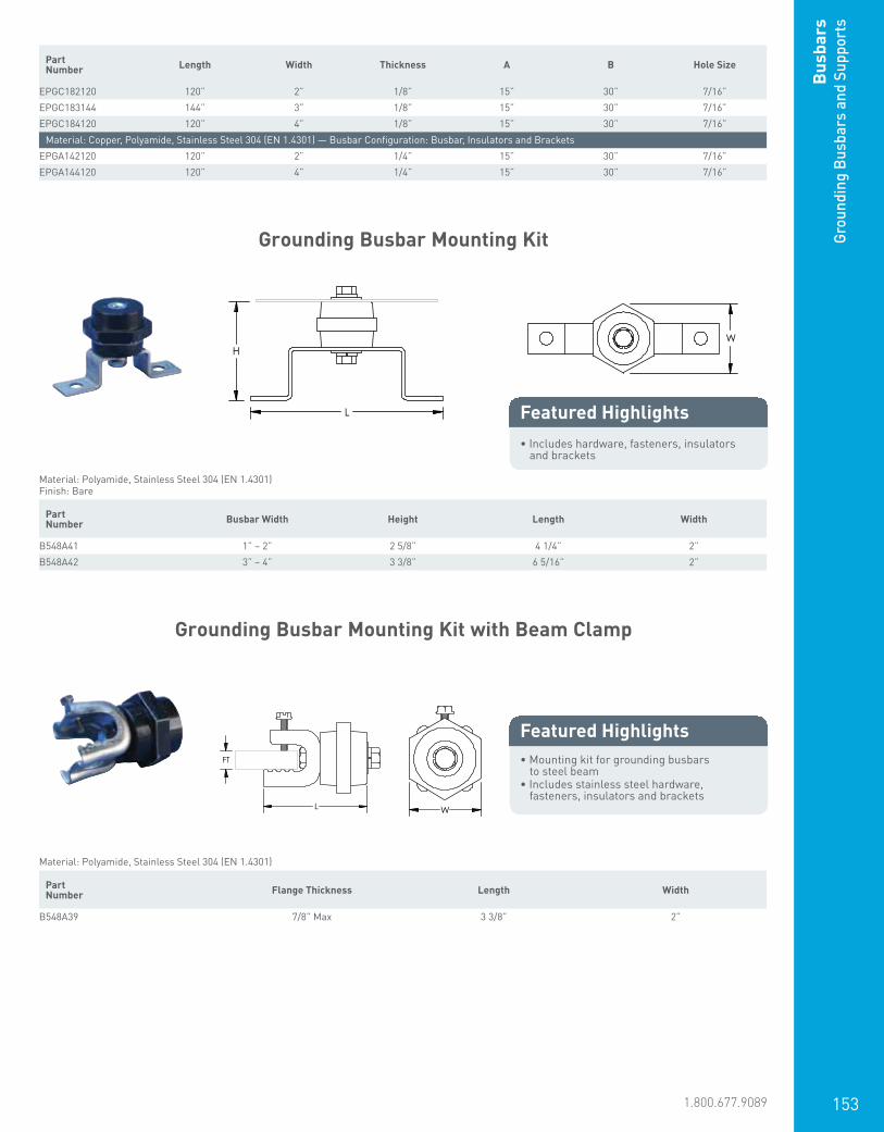
www.erico.pentair.com 1.800.677.9089 153
Bus
bars
Grou
ndin
g Bu
sbar
s an
d Su
ppor
ts
Part Number Length Width Thickness A B Hole Size
EPGC182120 120” 2” 1/8” 15” 30” 7/16”EPGC183144 144” 3” 1/8” 15” 30” 7/16”EPGC184120 120” 4” 1/8” 15” 30” 7/16”
Material: Copper, Polyamide, Stainless Steel 304 (EN 1.4301) — Busbar Configuration: Busbar, Insulators and BracketsEPGA142120 120” 2” 1/4” 15” 30” 7/16”EPGA144120 120” 4” 1/4” 15” 30” 7/16”
Grounding Busbar Mounting Kit
• Includes hardware, fasteners, insulators and brackets
Featured Highlights
H
L
Material: Polyamide, Stainless Steel 304 (EN 1.4301)Finish: Bare
Part Number Busbar Width Height Length Width
B548A41 1” – 2” 2 5/8” 4 1/4” 2”B548A42 3” – 4” 3 3/8” 6 5/16” 2”
Grounding Busbar Mounting Kit with Beam Clamp
• Mounting kit for grounding busbars to steel beam
• Includes stainless steel hardware, fasteners, insulators and brackets
Featured Highlights
L
FT
Material: Polyamide, Stainless Steel 304 (EN 1.4301) Part Number Flange Thickness Length Width
B548A39 7/8” Max 3 3/8” 2”
W
W

www.erico.pentair.com154
Busbars
Grounding Busbars and Supports
Theft-Deterrent Grounding Busbar, Flange Mount Assembly
• Mounts to a typical structural beam flange on a telecom tower without cutting or drilling the flange
• Accepts standard telecommunication grounding lugs (lugs not included)
• Includes 14 Standard Spacers (TDSGAS)
Featured Highlights
L1 L2
A
TS2
TS3TS1
Material: Copper, Stainless Steel 18-8 (EN 1.4305), NylonFinish: TinnedSpacer Thickness: 1/4”
Part Number Length 1 Length 2 Depth Height A Flange
Thickness Thread Size 1 Thread Size 2 Thread Size 3
TDSGABC14 10 1/2” 4” 2.13” 2.7” 1” 1/4” – 1” 3/8 UNC 5/16 UNC 5/16 UNC
Theft-Deterrent Grounding Busbar, Pole Mount Assembly
• Mounts on a standard Schedule 40 ice bridge pole (3.5” or 88.9 mm nominal outer diameter) and provides a path to the buried ground ring via a connection to the post
• This assembly eliminates the need for a solid copper busbar and down lead
• The connection to the ground ring is concealed below grade
• Accepts standard telecommunication grounding lugs (lugs not included)
• Includes 14 Standard Spacers (TDSGAS) and 2 Pole Mount Spacers (TDSGAP)
• Pole itself is not included in the assembly
Featured Highlights
L
A TS
Material: Copper, Stainless Steel 304 (EN 1.4301), Stainless Steel 18-8 (EN 1.4305)Finish: TinnedSpacer Thickness: 1/4”
Part Number Length A Thread Size
TDSGAPA14 10 1/2” 1” 3/8 UNC
D
H FT
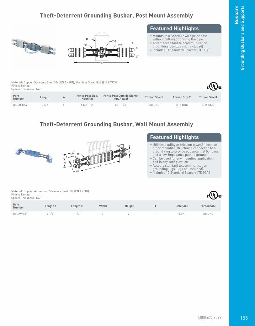
www.erico.pentair.com 1.800.677.9089 155
Bus
bars
Grou
ndin
g Bu
sbar
s an
d Su
ppor
ts
Theft-Deterrent Grounding Busbar, Post Mount Assembly
• Mounts to a Schedule 40 pipe or post without cutting or drilling the pipe
• Accepts standard telecommunication grounding lugs (lugs not included)
• Includes 14 Standard Spacers (TDSGAS)
Featured Highlights
L
A TS2
TS3TS1
Ø
Material: Copper, Stainless Steel 304 (EN 1.4301), Stainless Steel 18-8 (EN 1.4305)Finish: TinnedSpacer Thickness: 1/4”
Part Number Length A Fence Post Size,
NominalFence Post Outside Diame-
ter, Actual Thread Size 1 Thread Size 2 Thread Size 3
TDSGAPC14 10 1/2” 1” 1 1/2” – 2” 1.9” – 2.5” 3/8 UNC 5/16 UNC 5/16 UNC
Theft-Deterrent Grounding Busbar, Wall Mount Assembly
• Utilizes a utility or telecom tower's or other mounting structure’s connection to a ground ring to provide equipotential bonding and a low-impedance path to ground
• Can be used for any mounting application and in any configuration
• Accepts standard telecommunication grounding lugs (lugs not included)
• Includes 17 Standard Spacers (TDSGAS)
Featured Highlights
L2
W
A
HS
L1
TS
Material: Copper, Aluminum, Stainless Steel 304 (EN 1.4301)Finish: TinnedSpacer Thickness: 1/4”
Part Number Length 1 Length 2 Width Height A Hole Size Thread Size
TDSGAWB17 9 1/4” 1 1/2” 2” 2” 1” 0.39” 3/8 UNC
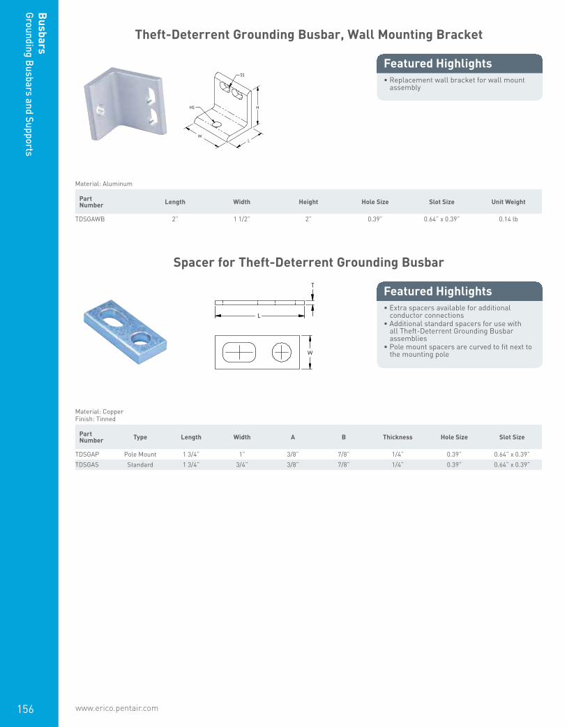
www.erico.pentair.com156
Busbars
Grounding Busbars and Supports
Theft-Deterrent Grounding Busbar, Wall Mounting Bracket
• Replacement wall bracket for wall mount assembly
Featured Highlights
W L
H HS
SS
Material: Aluminum Part Number Length Width Height Hole Size Slot Size Unit Weight
TDSGAWB 2” 1 1/2” 2” 0.39” 0.64” x 0.39” 0.14 lb
Spacer for Theft-Deterrent Grounding Busbar
• Extra spacers available for additional conductor connections
• Additional standard spacers for use with all Theft-Deterrent Grounding Busbar assemblies
• Pole mount spacers are curved to fit next to the mounting pole
Featured Highlights T
L
W
Material: CopperFinish: Tinned
Part Number Type Length Width A B Thickness Hole Size Slot Size
TDSGAP Pole Mount 1 3/4” 1” 3/8” 7/8” 1/4” 0.39” 0.64” x 0.39”TDSGAS Standard 1 3/4” 3/4” 3/8” 7/8” 1/4” 0.39” 0.64” x 0.39”

www.erico.pentair.com 1.800.677.9089 157
Bus
bars
Grou
ndin
g Bu
sbar
s an
d Su
ppor
ts
Grounding Standoff for Telecom Towers
• Provides a direct, low-impedance electrical ground connection to the tower
• Offers a quick installation process• Compact design fits in tight and confined
locations• Available in tinned copper to reduce
dissimilar metal issues• 6 TIA double-hole lug attachment points
Featured Highlights
Most equipment on a telecommunication tower is grounded by connecting a copper conductor to a ground bar mounted to the tower itself. The lead length of the conductor is often extensive, which can add resistance to the grounding system.
HS
H
Material: Copper, Stainless Steel 301 (EN 1.4310)Finish: Tinned
Part Number Diameter Height Hole Size
ETMAGS 5” Max 3” 3/8”
Earth Block
• Used to connect multiple earthing cables to a single point which then connects to the earthing system
• Two holes available (countersink M5) for installation of the earth block
Featured Highlights
W L
H HS1
HS3
HS2
Material: BrassFinish: Tinned
Part Number Length Width Height Hole Size 1 Hole Size 2 Hole Size 3
EBL08 3.465” 0.787” 0.512” 0.157” 0.204” 0.256”
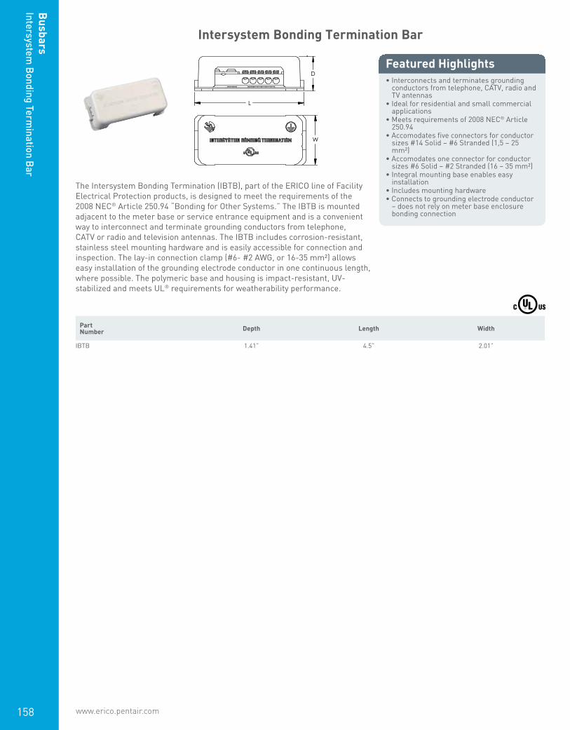
www.erico.pentair.com158
Busbars
Intersystem Bonding Term
ination Bar
Intersystem Bonding Termination Bar
• Interconnects and terminates grounding conductors from telephone, CATV, radio and TV antennas
• Ideal for residential and small commercial applications
• Meets requirements of 2008 NEC® Article 250.94
• Accomodates five connectors for conductor sizes #14 Solid – #6 Stranded (1,5 – 25 mm²)
• Accomodates one connector for conductor sizes #6 Solid – #2 Stranded (16 – 35 mm²)
• Integral mounting base enables easy installation
• Includes mounting hardware• Connects to grounding electrode conductor
– does not rely on meter base enclosure bonding connection
Featured Highlights
The Intersystem Bonding Termination (IBTB), part of the ERICO line of Facility Electrical Protection products, is designed to meet the requirements of the 2008 NEC® Article 250.94 “Bonding for Other Systems.” The IBTB is mounted adjacent to the meter base or service entrance equipment and is a convenient way to interconnect and terminate grounding conductors from telephone, CATV or radio and television antennas. The IBTB includes corrosion-resistant, stainless steel mounting hardware and is easily accessible for connection and inspection. The lay-in connection clamp (#6- #2 AWG, or 16-35 mm²) allows easy installation of the grounding electrode conductor in one continuous length, where possible. The polymeric base and housing is impact-resistant, UV-stabilized and meets UL® requirements for weatherability performance.
L
D
W
Part Number Depth Length Width
IBTB 1.41” 4.5” 2.01”

159www.erico.pentair.com 1.800.831.7133
GROUNDING TOOLS
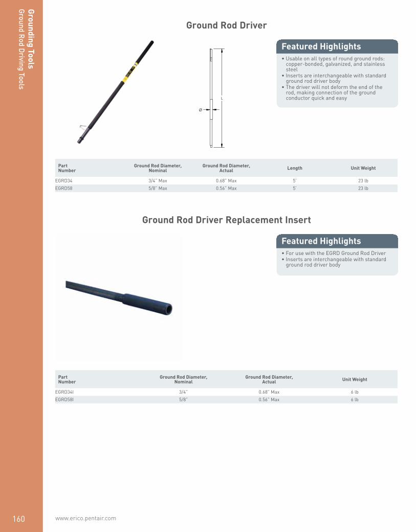
www.erico.pentair.com 1.800.677.9089160
Grounding ToolsGround Rod Driving Tools
Ground Rod Driver
• Usable on all types of round ground rods: copper-bonded, galvanized, and stainless steel
• Inserts are interchangeable with standard ground rod driver body
• The driver will not deform the end of the rod, making connection of the ground conductor quick and easy
Featured Highlights
L
Ø
Part Number
Ground Rod Diameter, Nominal
Ground Rod Diameter, Actual Length Unit Weight
EGRD34 3/4” Max 0.68” Max 5’ 23 lbEGRD58 5/8” Max 0.56” Max 5’ 23 lb
Ground Rod Driver Replacement Insert
• For use with the EGRD Ground Rod Driver• Inserts are interchangeable with standard
ground rod driver body
Featured Highlights
Part Number
Ground Rod Diameter, Nominal
Ground Rod Diameter, Actual Unit Weight
EGRD34I 3/4” 0.68” Max 6 lbEGRD58I 5/8” 0.56” Max 6 lb

www.erico.pentair.com 1.800.677.9089 161
Grou
ndin
g To
ols
Grou
nd R
od D
rivi
ng T
ools
Ground Rod Driving Head for Power Tools
•
Featured Highlights
L
Ø1
Ø2
Material: SteelGround Rod Type: Copper-bonded, Galvanized
Part Number
Ground Rod Diameter, Nominal Diameter 1 Diameter 2 Length
DH34 3/4” 0.78” 0.85” 7”DH58 5/8” 0.58” 0.85” 7”
Ground Rod Driving Head for Rotary Hammer
• Ground rod driving head for use with a rotary hammer
Featured Highlights
L
2
1
3
Material: SteelGround Rod Type: Copper-bonded, Galvanized
Part Number
Ground Rod Diameter, Nominal Diameter 1 Diameter 2 Diameter 3 Length
B13716RH15 5/8” 0.58” 0.74” 0.64” 7.7”

www.erico.pentair.com162
Grounding ToolsGround Rod Driving Tools
Ground Rod Driving Stud for Rotary Hammer with Coupler
• Used in conjunction with a CC58 ground rod coupler to drive a pointed ground rod
• DSCC58 driving stud fits inside CC58 coupler, then the assembly is placed on top of the ground rod
• Hammering is then carried out on the DSCC58
Featured Highlights
L
Ø1
Ø2
Material: SteelGround Rod Type: Copper-bonded
Part Number Ground Rod Diameter, Nominal Diameter 1 Diameter 2 Length
DSCC58 5/8” 0.78” 0.52” 2”
Ground Rod Drive Sleeve for Pointed Ground Rods
• For use with unthreaded ground rods• Slides on top of ground rod to prevent
mushrooming while driving into ground
Featured Highlights
L
Ø
Material: SteelGround Rod Type: Copper-bonded, Galvanized
Part Number Ground Rod Diameter, Nominal Diameter Length
158380 5/8” 0.63” 2.6”B13714 1/2” 0.52” 6.0”B13716 5/8” 0.58” 6.0”B13718 3/4” 0.70” 6.0”B13722 1” 0.94” 6.0”B13731 5/8” 0.64” 6.0”B13733 3/4” 0.77” 6.0”B13737 1” 1.02” 6.0”DH12M 1/2” 0.53” 3.9”DH34M 3/4” 0.79” 3.9”DH58M 5/8” 0.63” 3.9”EDS12 1/2” 0.53” 2.5”EDS58 5/8” 0.58” 2.5”

www.erico.pentair.com 1.800.677.9089 163
Grou
ndin
g To
ols
Grou
nd R
od D
rivi
ng T
ools
Ground Rod Driving Stud for Sectional Ground Rods
• Used in conjuction with threaded couplers while driving sectional ground rods
Featured Highlights
L
TS
Material: Steel Part Number Ground Rod Diameter, Nominal Thread Size Length
158100 5/8” 5/8 UNC 1.25”158110 3/4” 3/4 UNC 1.50”710090 3/8” M10 0.71”710100 3/8” M10 0.83”DS1 1” 1 UNC 2.50”DS12 1/2” 1/2 UNC 1.50”DS12S 1/2” 9/16 UNC 1.75”DS34 3/4” 3/4 UNC 2.00”DS58 5/8” 5/8 UNC 1.75”DS58C 5/8” 5/8 UNC 1.44”
Ground Rod Driving Point for Sectional Ground Rods
• Threaded ground rod driving tip to assist in driving sectional ground rods into the earth
Featured Highlights
L
TS
Material: Steel Part Number Ground Rod Diameter, Nominal Thread Size Length
SDT34 3/4” 3/4 UNC 1.7”SDT58 5/8” 5/8 UNC 1.7”

www.erico.pentair.com164
Grounding ToolsGround Resistance Testers
2- and 3-Point Ground Resistance Tester Kit
• Measures ground resistance (2- and 3-Point) Fall-of-Potential method
• Provides high-breaking fuse protection capacity, 0.1A, >250V
• Auto-ranging: automatically selects the optimum range
• Color-coded terminals and lead identification
• Extremely simple to operate: connect – press – hold – read
• Designed to reject high levels of noise and interference
• Large LCD digital display• Rugged dustproof and rainproof field case• Battery-powered, with low battery indication• Includes eight 1.5V AA batteries to
power approximately 1800 15-second measurements
Featured Highlights
Part Number EST3640
Soil Resistivity Test No
Measurement Range 0 – 2,000 Ω
Resolution 10 mΩ – 1 Ω
Test Current 10.0 – 0.1 mA
Open Voltage 42 V Max
Operating Frequency 128 Hz square wave
Accuracy 3% of Reading +/- 3ct5% of Reading +/- 3ct
Unit Weight 35 lb
Kit includes: Two 300’ (91.4 m) color-coded leads on spools (red and blue), two 5’ (1.5 m) color-coded leads (red and blue), two 100’ (30.5 m) color-coded leads (green and black), four 14.5” (368 mm) T-shaped auxiliary ground electrodes, one set of five-spaded lugs, one 100’ (30.5 m) tape measure, and one carrying bag.

www.erico.pentair.com 1.800.677.9089 165
Grou
ndin
g To
ols
Grou
nd R
esis
tanc
e Te
ster
s
2-, 3- and 4-Point Ground Resistance Tester Kit
• Measures ground resistance (2- and 3-Point) Fall-of-Potential method and soil resistivity (4-Point)
• Fuse protection of 0.1A, >250V, 0.25 x 1.25” with 30kA Interrupt Capacity
• Both models will perform over 2,000 measurements of the 15-second tests between recharging or battery replacement
• Provides a response time of approximately four to eight seconds for a stabilized measurement
• Step voltage tests and touch potential measurements• Auto-ranging: automatically selects the optimum
resistance range and test current• Designed to reject high levels of noise and interference• Extremely simple to operate: connect – press – hold –
read • May also be used for continuity tests on bonding• Large easy-to-read backlit display• LED on faceplate informs operator of high input noise,
high auxiliary rod resistance and fault connections• Rugged dustproof and rainproof field case• Color-coded terminals• Low battery indication
Featured Highlights
Part Number
Soil Resistivity
TestMeasurement
Range Resolution Open Voltage
Test Current
Operating Frequency Accuracy
Auxillary Electrode Influence
Withstanding Voltage
Unit Weight
EST4620 Yes 0 – 2,000 Ω 10 mΩ – 1 Ω 42 V Max 10.0 – 0.1 mA 128 Hz
square wave2% of Reading +/- 1ct, 5% of Reading
+/- 3ct3 – 50 kΩ 250 VAC,
100 VDC 35 lb
EST4630 Yes 0 – 2,000 Ω 10 mΩ – 1 Ω 42 V Max 10.0 – 0.1 mA 128 Hz
square wave2% of Reading +/- 1ct, 5% of Reading
+/- 3ct3 – 50 kΩ 250 VAC,
100 VDC 35 lb
Kit includes: Two 300’ (91.4 m) color-coded leads on spools (red and blue), two 5’ (1.5 m) color-coded leads (red and blue), two 100’ (30.5 m) color-coded leads (green and black), four 14.5” (368 mm) T-shaped auxiliary ground electrodes, one set of five-spaded lugs, one 100’ (30.5 m) tape measure, and one carrying bag.

www.erico.pentair.com166
Grounding ToolsGround Resistance Testers
2-, 3- and 4-Point Ground Resistance Tester Kit with DataView® Software
• Measures Ground Impedance at frequencies up to 5kHz to test lightning strike protection
• Ground Resistance testing using the 2 clamp method (no auxiliary rods needed) using optional current probes
• Includes DataView® software for data storage, real-time display, analysis, report generation and system configuration
• 3-Point Fall-of-Potential measurement with manual or automatic frequency selection
• Used under difficult conditions such as the presence of high-stray currents that normally affect accuracy
• Automatic report generation including the fall of potential plot
• 4-Point soil resistivity measurement with automatic calculation of Rho and user selection of Wenner or Schlumberger test method
• 3-Point earth coupling measurement• Manual and automatic frequency scan from
41 to 5,078Hz for optimum test accuracy in electrically-noisy environments
• Selectable test voltage of 16 or 32V up to 250mA of test current
• 2- and 4-Wire Bond Resistance/Continuity Measurement (DC Resistance) with automatic polarity reversal
• Stores up to 512 complete test results in internal memory
• Optically isolated USB communication included
• Display with automatic backlight when entering a function
• Rugged dustproof and rainproof field case - IP53 rated in closed position
• AC-powered with rechargeable NiMH batteries from wall charger or vehicle power
• Auto-off power management
Featured Highlights
Part Number
EST6472
Kit includes: Two 300’ (91.4 m) color-coded leads on spools (red and blue), two 5’ (1.5 m) color-coded leads (red and blue), two 100’ (30.5 m) color-coded leads (green and black), four 14.5” (368 mm) T-shaped auxiliary ground electrodes, one set of five-spaded lugs, one 100’ (30.5 m) tape measure, and one carrying bag.Ground Resistance Tester Clamp-On Probe is not included and must be ordered separately.
Ground Resistance Tester Information
3-Point Measurement
Range (Auto-Ranging) 0.09Ω to 99.9kΩ
Resolution 0.01Ω to 100Ω
Test Voltage Nominal 16 or 32Vrms user selectable
Operating Frequency 41 to 5078Hz automatic or user selectable
Test Current Up to 250mA
Accuracy ±2% of Reading + 1ct @ 128Hz
2-Clamp Measurement
Range 0.1 to 500Ω
Resolution 0.01 to 1Ω
Operating Frequency Auto: 1367Hz; Manual: 128Hz-1367Hz-1611Hz-1758Hz
Soil Resistivity 4-Point Measurement
Test Method Wenner or Schlumberger selectable with automatic calculation of test results in Ω-meters
Range (Auto-Ranging) 0.01 to 99.99kΩ; ρ max: 999kΩm

www.erico.pentair.com 1.800.677.9089 167
Grou
ndin
g To
ols
Grou
nd R
esis
tanc
e Te
ster
s
Resolution 0.01 to 100Ω
Test Voltage 16 or 32V user selectable
Operating Frequency From 41 to 128Hz selectable
External Voltage Measurement
Range (Auto-Ranging) 0.1 to 65.0VAC/DC – DC to 440Hz
Accuracy ±2% of Reading + 1ct
Resistance Measurement (Bond Testing)
Measurement Type 2-Pole (with lead resistance compensation) or 4-Pole (Kelvin sensing) user selectable
Range (Auto-Ranging) 2-Pole 0.02Ω to 99.99kΩ; 4-Pole 0.02Ω to 99.99kΩ
Accuracy ±2% of Reading + 2cts
Test Voltage 16VDC (+, - or auto polarity)
Test Current Up to 250mA max
Data Storage
Memory Capacity 512 test results (64KB)
Power
Power Source 9.6V rechargeable battery pack (included)
Recharging Source 110/220 50/60Hz external charger with 18Vdc, 1.9A output
Kit includes: Two 300’ (91.4 m) color-coded leads on spools (red and blue), two 5’ (1.5 m) color-coded leads (red and blue), two 100’ (30.5 m) color-coded leads (green and black), four 14.5” (368 mm) T-shaped auxiliary ground electrodes, one set of five-spaded lugs, one 100’ (30.5 m) tape measure, and one carrying bag.Ground Resistance Tester Clamp-On Probe is not included and must be ordered separately.Pentair, CADDY, CADWELD, CRITEC, ERICO, ERIFLEX and LENTON are owned by Pentair or its global affiliates. All other trademarks are the property of their respective owners. Pentair reserves the right to change specifications without prior notice.
DataView is a registered trademark of Chauvin Arnoux, Inc.

www.erico.pentair.com168
Handheld Clamp-On Ground Resistance Tester
• Measures earth resistance without need to disconnect from the electrical system or need for auxillary ground electrodes or reels
• Ground Resistance is auto-ranging from 1 to 199Ω• Current Measurement is auto-ranging from 1mA to 40A• Ground voltage indication - warns of unsafe conditions• Clamping diameter of 1.4” (35 mm) with large jaw design• Stores up to 300 measurements• Includes a hard carrying case, calibration loop, four 1.5V AA
batteries and a user manual
Featured Highlights
Part Number
Ground Resistance
Measurement Range
Ground Resistance Resolution
Ground Resistance Accuracy
Current Measurement
Range
Current Measurement
Resolution
Current Measurement
Accuracy
Current Measurement
FrequencyOperating Frequency
Loop Impedance
Measurement
EST401 0.01 – 1,500.00 Ω 0.001 – 50.000 Ω Approx. 1.5% - 25% 0.20 mA – 39.99 A 1 µA – 10 mA +/- 2% 47 – 800 Hz 2,083 Hz 10 to 100μH;
100 to 500μH
Ground Resistance Tester Clamp-On Probe
• AC Clamp-on probe for use with EST6472• Extends use of EST6472 to be used as a
clamp-on ground resistance tester
Featured Highlights
Part Number Unit Weight
ESR182 3 lb
Grounding ToolsGround Resistance Testers

www.erico.pentair.com 1.800.677.9089 169
Ground Resistance Tester Cable Reel
• Includes two reels of silicone rubber insulated wire—one reel is red and the other reel is blue—for easy stake identification
• The far end of test lead remains attached to the reel base, which eliminates tangling and speeds up the process of test stake deployment
• Each reel includes 500' (152.4 m) of cable, a screwdriver and a lead that connects the reel to the test meter
Featured Highlights
Part Number Cable Length Unit Weight
ESTREELKIT500 500’ 17 lb
Grou
ndin
g To
ols
Grou
nd R
esis
tanc
e Te
ster
s

www.erico.pentair.com170

171www.erico.pentair.com 1.800.831.7133
ERICO CADWELDMOLDS
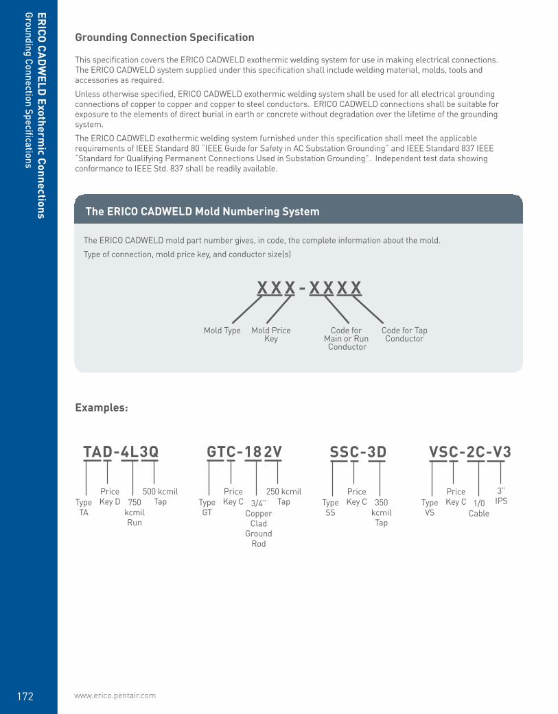
www.erico.pentair.com172
Grounding Connection Specification
This specification covers the ERICO CADWELD exothermic welding system for use in making electrical connections. The ERICO CADWELD system supplied under this specification shall include welding material, molds, tools and accessories as required.
Unless otherwise specified, ERICO CADWELD exothermic welding system shall be used for all electrical grounding connections of copper to copper and copper to steel conductors. ERICO CADWELD connections shall be suitable for exposure to the elements of direct burial in earth or concrete without degradation over the lifetime of the grounding system.
The ERICO CADWELD exothermic welding system furnished under this specification shall meet the applicable requirements of IEEE Standard 80 “IEEE Guide for Safety in AC Substation Grounding” and IEEE Standard 837 IEEE “Standard for Qualifying Permanent Connections Used in Substation Grounding”. Independent test data showing conformance to IEEE Std. 837 shall be readily available.
The ERICO CADWELD mold part number gives, in code, the complete information about the mold.
Type of connection, mold price key, and conductor size(s)
X X X - X X X X
Examples:
Mold Type Code forMain or Run Conductor
Mold PriceKey
Code for TapConductor
SSC-3D
Type SS
350 kcmil Tap
Price Key C
TAD-4L3Q
Type TA
750 kcmil Run
Price Key D
500 kcmil Tap
GTC-18 2V
Type GT
3/4” Copper
Clad Ground
Rod
Price Key C
250 kcmil Tap
VSC-2C-V3
Type VS
1/0 Cable
Price Key C
3” IPS
The ERICO CADWELD Mold Numbering System
ERICO
CADW
ELD Exotherm
ic ConnectionsGrounding Connection Specifications

www.erico.pentair.com 1.800.677.9089 173
ERIC
O C
ADW
ELD
Exo
ther
mic
Con
nect
ions
Grou
ndin
g Co
nnec
tion
Spec
ifica
tions
CADWELD Connections Used for Grounding Reinforcing BarsCADWELD provides efficient and permanent connections for both grounding and attaching lightning protection conductors to rebar. When making CADWELD connections to rebar, the normal materials required are: mold, handle and weld metal. In addition, packing material is also required. These materials act as a seal between the mold and rebar to prevent leaks. One unit of packing material must be ordered for each weld.
CADWELD Connections to Structural Reinforcing Bar and Anchor BoltsWelding of ground conductors to reinforcing bars (rebar) by the CADWELD process should not be harmful if stresses in the rebar are below yield. As design stresses are normally only about 50% to 60% of the nominal yield strength of the rebar, welding by the CADWELD process should not be detrimental under design stresses.
As the ACI Building Code (ACI318-14 Commentary, 25.5.2.1) advises, “splice requirements encourage splicing bars at points of minimum stress … encourage the location of splices away from regions of high tensile stress.” The same advice should apply to locations of CADWELD connections of a ground conductor to rebar. Where possible, locate the weld area away from areas of maximum tensile stress, e.g., near the free end of the bar in a lap splice, on the hook extension for a hooked bar, etc. The same considerations apply to CADWELD connections to anchor bolts.
For lightning protection applications where the main lightning protection conductor is connected to the rebar, ERICO recommends a 2/0 AWG copper conductor for structures over 75 feet in height and a #2 AWG copper conductor for structures under 75 feet. For a bonding conductor, a #6 AWG copper may be used. These sizes meet NFPA78 Code requirement. Anchor bolts are connected in the same way.
All welds to rebar requiring larger than a #150 weld metal will be sold only after review by ERICO.
NOTE:

www.erico.pentair.com174
Cable to Cable
• Forms a permanent, low resistance connection
• Provides a molecular bond• ERICO CADWELD Exothermic Connections
are rated with the same current capacity as the conductor
• Portable installation equipment with no external source of power required
• Installers can be easily trained to make ERICO CADWELD Exothermic Connections
• Connections are visually inspected
Global Part Number
Mold Family Price Key Conductor 1 Conductor 2 Welding Material Ease of Use
Handle Clamp (Sold separately unless noted)
SSC1D SS C #8 Solid #8 Solid 25 or 25PLUSF20 Preferred L160
SSC1G SS C #6 Solid #6 Solid 25 or 25PLUSF20 Preferred L160
SSC1H SS C #6 Concentric #6 Concentric 25 or 25PLUSF20 Preferred L160
SSC1K SS C #4 Solid #4 Solid 45 or 45PLUSF20 Preferred L160
SSC1L SS C #4 Concentric #4 Concentric 25 or 25PLUSF20 Preferred L160
SSC1T SS C #2 Solid #2 Solid 32 or 32PLUSF20 Preferred L160
SSC1V SS C #2 Concentric #2 Concentric 32 or 32PLUSF20 Preferred L160
SSC1Y SS C #1 Concentric #1 Concentric 32 or 32PLUSF20 Preferred L160
SSC2C SS C 1/0 Concentric 1/0 Concentric 45 or 45PLUSF20 Preferred L160
SSC2G SS C 2/0 Concentric 2/0 Concentric 65 or 65PLUSF20 Preferred L160
SSC2Q SS C 4/0 Concentric 4/0 Concentric 90 or 90PLUSF20 Preferred L160
SSC2V SS C 250 kcmil Concentric 250 kcmil Concentric 115 or 115PLUSF20 Preferred L160
SSC3A SS C 300 kcmil Concentric 300 kcmil Concentric 115 or 115PLUSF20 Preferred L160
SSC3D SS C 350 kcmil Concentric 350 kcmil Concentric 150 or 150PLUSF20 Preferred L160
SSC3H SS C 400 kcmil Concentric 400 kcmil Concentric 150 or 150PLUSF20 Preferred L160
SSC3Q SS C 500 kcmil Concentric 500 kcmil Concentric 200 or 200PLUSF20 Preferred L160
SSC4L SS C 750 kcmil Concentric 750 kcmil Concentric 150 x 2 or 300PLUSF20 Preferred L160
SSD4Y SS D 1000 kcmil Concentric 1000 kcmil Concentric 200 x 2 or 400PLUSF20 Preferred L159
SST1G SS T #6 Solid #6 Solid 25 or 25PLUSF20 Preferred Clamp Included
SST1K SS T #4 Solid #4 Solid 25 or 25PLUSF20 Preferred Clamp Included
SST1L SS T #4 Concentric #4 Concentric 25 or 25PLUSF20 Preferred Clamp Included
SST1T SS T #2 Solid #2 Solid 32 or 32PLUSF20 Preferred Clamp Included
SST1V SS T #2 Concentric #2 Concentric 32 or 32PLUSF20 Preferred Clamp Included
SS Molds
ERICO
CADW
ELD Exotherm
ic ConnectionsCable to Cable M
olds

www.erico.pentair.com 1.800.677.9089 175
PC Molds
Global Part Number
Mold Family Price Key Conductor 1 Conductor 2 Welding Material Ease of Use
Handle Clamp (Sold separately unless noted)
PCC1G1G PC C #6 Solid #6 Solid 25 or 25PLUSF20 Preferred L160
PCC1G1H PC C #6 Solid #6 Concentric 25 or 25PLUSF20 Preferred L160
PCC1H1H PC C #6 Concentric #6 Concentric 25 or 25PLUSF20 Preferred L160
PCC1K1G PC C #4 Solid #6 Solid 32 or 32PLUSF20 Preferred L160
PCC1K1K PC C #4 Solid #4 Solid 32 or 32PLUSF20 Preferred L160
PCC1L1G PC C #4 Concentric #6 Solid 32 or 32PLUSF20 Preferred L160
PCC1L1H PC C #4 Concentric #6 Concentric 32 or 32PLUSF20 Preferred L160
PCC1L1L PC C #4 Concentric #4 Concentric 32 or 32PLUSF20 Preferred L160
PCC1T1G PC C #2 Solid #6 Solid 32 or 32PLUSF20 Preferred L160
PCC1T1H PC C #2 Solid #6 Concentric 32 or 32PLUSF20 Preferred L160
PCC1T1T PC C #2 Solid #2 Solid 65 or 65PLUSF20 Preferred L160
PCC1T1V PC C #2 Solid #2 Concentric 65 or 65PLUSF20 Preferred L160
PCC1V1G PC C #2 Concentric #6 Solid 32 or 32PLUSF20 Preferred L160
PCC1V1H PC C #2 Concentric #6 Concentric 32 or 32PLUSF20 Preferred L160
PCC1V1L PC C #2 Concentric #4 Concentric 45 or 45PLUSF20 Preferred L160
PCC1V1T PC C #2 Concentric #2 Solid 65 or 65PLUSF20 Preferred L160
PCC1V1V PC C #2 Concentric #2 Concentric 65 or 65PLUSF20 Preferred L160
PCC1Y1G PC C #1 Concentric #6 Solid 45 or 45PLUSF20 Preferred L160
PCC1Y1H PC C #1 Concentric #6 Concentric 45 or 45PLUSF20 Preferred L160
PCC1Y1V PC C #1 Concentric #2 Concentric 65 or 65PLUSF20 Preferred L160
PCC1Y1Y PC C #1 Concentric #1 Concentric 65 or 65PLUSF20 Preferred L160
PCC2C1G PC C 1/0 Concentric #6 Solid 45 or 45PLUSF20 Preferred L160
PCC2C1H PC C 1/0 Concentric #6 Concentric 45 or 45PLUSF20 Preferred L160
PCC2C1K PC C 1/0 Concentric #4 Solid 65 or 65PLUSF20 Preferred L160
PCC2C1L PC C 1/0 Concentric #4 Concentric 65 or 65PLUSF20 Preferred L160
PCC2C1T PC C 1/0 Concentric #2 Solid 65 or 65PLUSF20 Preferred L160
PCC2C1V PC C 1/0 Concentric #2 Concentric 65 or 65PLUSF20 Preferred L160
PCC2C2C PC C 1/0 Concentric 1/0 Concentric 90 or 90PLUSF20 Preferred L160
PCC2G1G PC C 2/0 Concentric #6 Solid 65 or 65PLUSF20 Preferred L160
PCC2G1H PC C 2/0 Concentric #6 Concentric 65 or 65PLUSF20 Preferred L160
PCC2G1L PC C 2/0 Concentric #4 Concentric 65 or 65PLUSF20 Preferred L160
PCC2G1T PC C 2/0 Concentric #2 Solid 90 or 90PLUSF20 Preferred L160
PCC2G1V PC C 2/0 Concentric #2 Concentric 90 or 90PLUSF20 Preferred L160
PCC2G1Y PC C 2/0 Concentric #1 Concentric 115 or 115PLUSF20 Preferred L160
PCC2G2G PC C 2/0 Concentric 2/0 Concentric 115 or 115PLUSF20 Preferred L160
PCC2Q1G PC C 4/0 Concentric #6 Solid 90 or 90PLUSF20 Preferred L160
PCC2Q1H PC C 4/0 Concentric #6 Concentric 90 or 90PLUSF20 Preferred L160
PCC2Q1K PC C 4/0 Concentric #4 Solid 90 or 90PLUSF20 Preferred L160
PCC2Q1L PC C 4/0 Concentric #4 Concentric 90 or 90PLUSF20 Preferred L160
PCC2Q1T PC C 4/0 Concentric #2 Solid 115 or 115PLUSF20 Preferred L160
ERIC
O C
ADW
ELD
Exo
ther
mic
Con
nect
ions
Cabl
e to
Cab
le M
olds

www.erico.pentair.com176
PCC2Q1V PC C 4/0 Concentric #2 Concentric 115 or 115PLUSF20 Preferred L160
PCC2Q1Y PC C 4/0 Concentric #1 Concentric 115 or 115PLUSF20 Preferred L160
PCC2Q2C PC C 4/0 Concentric 1/0 Concentric 115 or 115PLUSF20 Preferred L160
PCC2Q2G PC C 4/0 Concentric 2/0 Concentric 115 or 115PLUSF20 Preferred L160
PCC2Q2Q PC C 4/0 Concentric 4/0 Concentric 150 or 150PLUSF20 Preferred L160
PCC2V2G PC C 250 kcmil Concentric 2/0 Concentric 150 or 150PLUSF20 Preferred L160
PCC2V2Q PC C 250 kcmil Concentric 4/0 Concentric 200 or 200PLUSF20 Preferred L160
PCC2V2V PC C 250 kcmil Concentric 250 kcmil Concentric 200 or 200PLUSF20 Preferred L160
PCC3Q2Q PC C 500 kcmil Concentric 4/0 Concentric 200 or 200PLUSF20 Preferred L160
PCC3Q3Q PC C 500 kcmil Concentric 500 kcmil Concentric 150 x 2 or 300PLUSF20 Preferred L160
PCD4L4L PC D 750 kcmil Concentric 750 kcmil Concentric 200 x 3 or 600PLUSF20 Preferred L159
PCT1H1H PC T #6 Concentric #6 Concentric 25 or 25PLUSF20 Preferred Clamp Included
PCT1L1D PC T #4 Concentric #8 Solid 32 or 32PLUSF20 Preferred Clamp Included
PCT1L1G PC T #4 Concentric #6 Solid 32 or 32PLUSF20 Preferred Clamp Included
PCT1L1H PC T #4 Concentric #6 Concentric 32 or 32PLUSF20 Preferred Clamp Included
PCT1T1G PC T #2 Solid #6 Solid 32 or 32PLUSF20 Preferred Clamp Included
PCT1T1H PC T #2 Solid #6 Concentric 32 or 32PLUSF20 Preferred Clamp Included
PCT1V1D PC T #2 Concentric #8 Solid 32 or 32PLUSF20 Preferred Clamp Included
PCT1V1G PC T #2 Concentric #6 Solid 32 or 32PLUSF20 Preferred Clamp Included
PCT1V1H PC T #2 Concentric #6 Concentric 32 or 32PLUSF20 Preferred Clamp Included
Global Part Number
Mold Family Price Key Conductor 1 Conductor 2 Welding Material Ease of Use
Handle Clamp (Sold separately unless noted)
TAC1D1D TA C #8 Solid #8 Solid 32 or 32PLUSF20 Preferred L160
TAC1G1G TA C #6 Solid #6 Solid 32 or 32PLUSF20 Preferred L160
TAC1G1H TA C #6 Solid #6 Concentric 32 or 32PLUSF20 Preferred L160
TAC1H1H TA C #6 Concentric #6 Concentric 32 or 32PLUSF20 Preferred L160
TAC1K1K TA C #4 Solid #4 Solid 32 or 32PLUSF20 Preferred L160
TAC1K1L TA C #4 Solid #4 Concentric 32 or 32PLUSF20 Preferred L160
TAC1L1H TA C #4 Concentric #6 Concentric 32 or 32PLUSF20 Preferred L160
TAC1L1L TA C #4 Concentric #4 Concentric 32 or 32PLUSF20 Preferred L160
TAC1T1G TA C #2 Solid #6 Solid 45 or 45PLUSF20 Preferred L160
TAC1T1H TA C #2 Solid #6 Concentric 45 or 45PLUSF20 Preferred L160
TAC1T1K TA C #2 Solid #4 Solid 45 or 45PLUSF20 Preferred L160
TAC1T1L TA C #2 Solid #4 Concentric 45 or 45PLUSF20 Preferred L160
TAC1T1T TA C #2 Solid #2 Solid 45 or 45PLUSF20 Preferred L160
TAC1T1V TA C #2 Solid #2 Concentric 45 or 45PLUSF20 Preferred L160
TAC1V1G TA C #2 Concentric #6 Solid 45 or 45PLUSF20 Preferred L160
TAC1V1H TA C #2 Concentric #6 Concentric 45 or 45PLUSF20 Preferred L160
TA Molds
ERICO
CADW
ELD Exotherm
ic ConnectionsCable to Cable M
olds
Global Part Number
Mold Family Price Key Conductor 1 Conductor 2 Welding Material Ease of Use
Handle Clamp (Sold separately unless noted)
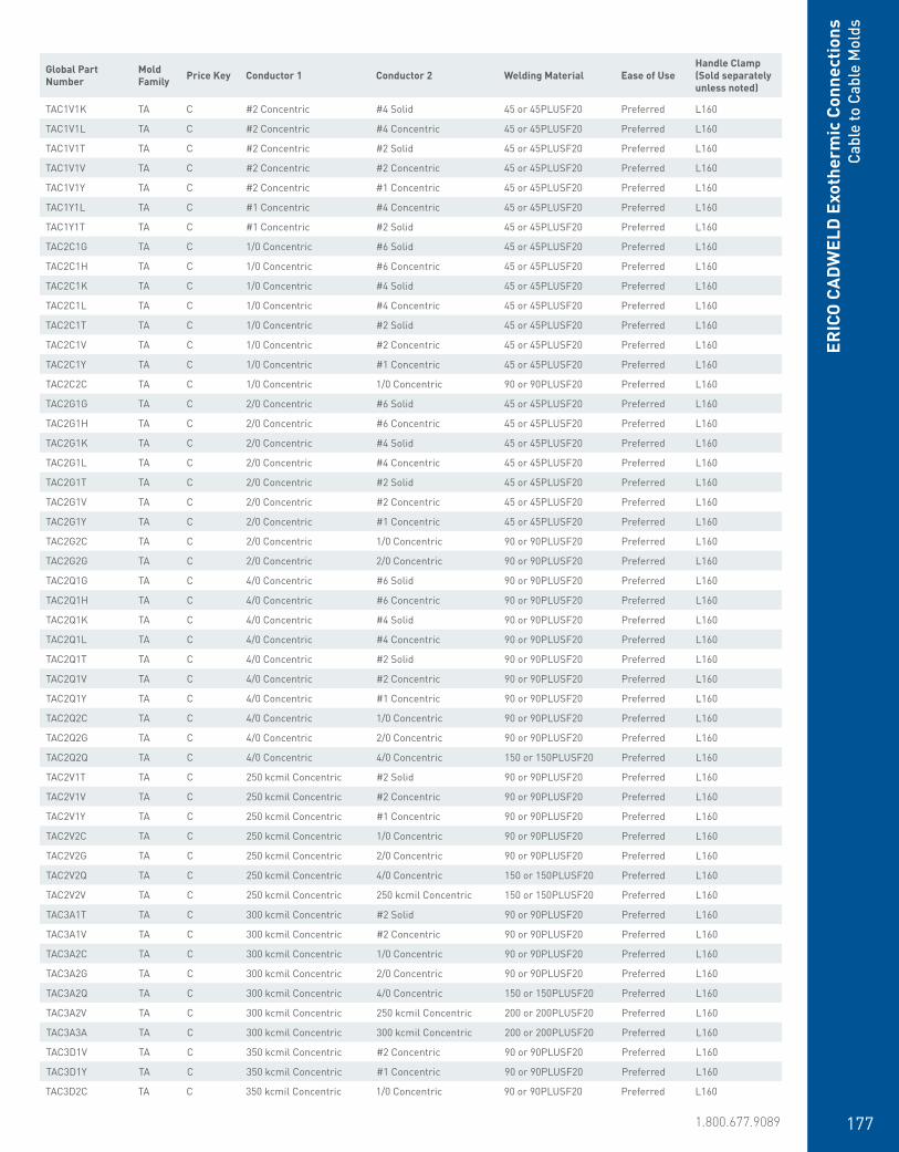
www.erico.pentair.com 1.800.677.9089 177
Global Part Number
Mold Family Price Key Conductor 1 Conductor 2 Welding Material Ease of Use
Handle Clamp (Sold separately unless noted)
TAC1D1D TA C #8 Solid #8 Solid 32 or 32PLUSF20 Preferred L160
TAC1G1G TA C #6 Solid #6 Solid 32 or 32PLUSF20 Preferred L160
TAC1G1H TA C #6 Solid #6 Concentric 32 or 32PLUSF20 Preferred L160
TAC1H1H TA C #6 Concentric #6 Concentric 32 or 32PLUSF20 Preferred L160
TAC1K1K TA C #4 Solid #4 Solid 32 or 32PLUSF20 Preferred L160
TAC1K1L TA C #4 Solid #4 Concentric 32 or 32PLUSF20 Preferred L160
TAC1L1H TA C #4 Concentric #6 Concentric 32 or 32PLUSF20 Preferred L160
TAC1L1L TA C #4 Concentric #4 Concentric 32 or 32PLUSF20 Preferred L160
TAC1T1G TA C #2 Solid #6 Solid 45 or 45PLUSF20 Preferred L160
TAC1T1H TA C #2 Solid #6 Concentric 45 or 45PLUSF20 Preferred L160
TAC1T1K TA C #2 Solid #4 Solid 45 or 45PLUSF20 Preferred L160
TAC1T1L TA C #2 Solid #4 Concentric 45 or 45PLUSF20 Preferred L160
TAC1T1T TA C #2 Solid #2 Solid 45 or 45PLUSF20 Preferred L160
TAC1T1V TA C #2 Solid #2 Concentric 45 or 45PLUSF20 Preferred L160
TAC1V1G TA C #2 Concentric #6 Solid 45 or 45PLUSF20 Preferred L160
TAC1V1H TA C #2 Concentric #6 Concentric 45 or 45PLUSF20 Preferred L160
TAC1V1K TA C #2 Concentric #4 Solid 45 or 45PLUSF20 Preferred L160
TAC1V1L TA C #2 Concentric #4 Concentric 45 or 45PLUSF20 Preferred L160
TAC1V1T TA C #2 Concentric #2 Solid 45 or 45PLUSF20 Preferred L160
TAC1V1V TA C #2 Concentric #2 Concentric 45 or 45PLUSF20 Preferred L160
TAC1V1Y TA C #2 Concentric #1 Concentric 45 or 45PLUSF20 Preferred L160
TAC1Y1L TA C #1 Concentric #4 Concentric 45 or 45PLUSF20 Preferred L160
TAC1Y1T TA C #1 Concentric #2 Solid 45 or 45PLUSF20 Preferred L160
TAC2C1G TA C 1/0 Concentric #6 Solid 45 or 45PLUSF20 Preferred L160
TAC2C1H TA C 1/0 Concentric #6 Concentric 45 or 45PLUSF20 Preferred L160
TAC2C1K TA C 1/0 Concentric #4 Solid 45 or 45PLUSF20 Preferred L160
TAC2C1L TA C 1/0 Concentric #4 Concentric 45 or 45PLUSF20 Preferred L160
TAC2C1T TA C 1/0 Concentric #2 Solid 45 or 45PLUSF20 Preferred L160
TAC2C1V TA C 1/0 Concentric #2 Concentric 45 or 45PLUSF20 Preferred L160
TAC2C1Y TA C 1/0 Concentric #1 Concentric 45 or 45PLUSF20 Preferred L160
TAC2C2C TA C 1/0 Concentric 1/0 Concentric 90 or 90PLUSF20 Preferred L160
TAC2G1G TA C 2/0 Concentric #6 Solid 45 or 45PLUSF20 Preferred L160
TAC2G1H TA C 2/0 Concentric #6 Concentric 45 or 45PLUSF20 Preferred L160
TAC2G1K TA C 2/0 Concentric #4 Solid 45 or 45PLUSF20 Preferred L160
TAC2G1L TA C 2/0 Concentric #4 Concentric 45 or 45PLUSF20 Preferred L160
TAC2G1T TA C 2/0 Concentric #2 Solid 45 or 45PLUSF20 Preferred L160
TAC2G1V TA C 2/0 Concentric #2 Concentric 45 or 45PLUSF20 Preferred L160
TAC2G1Y TA C 2/0 Concentric #1 Concentric 45 or 45PLUSF20 Preferred L160
TAC2G2C TA C 2/0 Concentric 1/0 Concentric 90 or 90PLUSF20 Preferred L160
TAC2G2G TA C 2/0 Concentric 2/0 Concentric 90 or 90PLUSF20 Preferred L160
TAC2Q1G TA C 4/0 Concentric #6 Solid 90 or 90PLUSF20 Preferred L160
TAC2Q1H TA C 4/0 Concentric #6 Concentric 90 or 90PLUSF20 Preferred L160
TAC2Q1K TA C 4/0 Concentric #4 Solid 90 or 90PLUSF20 Preferred L160
TAC2Q1L TA C 4/0 Concentric #4 Concentric 90 or 90PLUSF20 Preferred L160
TAC2Q1T TA C 4/0 Concentric #2 Solid 90 or 90PLUSF20 Preferred L160
TAC2Q1V TA C 4/0 Concentric #2 Concentric 90 or 90PLUSF20 Preferred L160
TAC2Q1Y TA C 4/0 Concentric #1 Concentric 90 or 90PLUSF20 Preferred L160
TAC2Q2C TA C 4/0 Concentric 1/0 Concentric 90 or 90PLUSF20 Preferred L160
TAC2Q2G TA C 4/0 Concentric 2/0 Concentric 90 or 90PLUSF20 Preferred L160
TAC2Q2Q TA C 4/0 Concentric 4/0 Concentric 150 or 150PLUSF20 Preferred L160
TAC2V1T TA C 250 kcmil Concentric #2 Solid 90 or 90PLUSF20 Preferred L160
TAC2V1V TA C 250 kcmil Concentric #2 Concentric 90 or 90PLUSF20 Preferred L160
TAC2V1Y TA C 250 kcmil Concentric #1 Concentric 90 or 90PLUSF20 Preferred L160
TAC2V2C TA C 250 kcmil Concentric 1/0 Concentric 90 or 90PLUSF20 Preferred L160
TAC2V2G TA C 250 kcmil Concentric 2/0 Concentric 90 or 90PLUSF20 Preferred L160
TAC2V2Q TA C 250 kcmil Concentric 4/0 Concentric 150 or 150PLUSF20 Preferred L160
TAC2V2V TA C 250 kcmil Concentric 250 kcmil Concentric 150 or 150PLUSF20 Preferred L160
TAC3A1T TA C 300 kcmil Concentric #2 Solid 90 or 90PLUSF20 Preferred L160
TAC3A1V TA C 300 kcmil Concentric #2 Concentric 90 or 90PLUSF20 Preferred L160
TAC3A2C TA C 300 kcmil Concentric 1/0 Concentric 90 or 90PLUSF20 Preferred L160
TAC3A2G TA C 300 kcmil Concentric 2/0 Concentric 90 or 90PLUSF20 Preferred L160
TAC3A2Q TA C 300 kcmil Concentric 4/0 Concentric 150 or 150PLUSF20 Preferred L160
TAC3A2V TA C 300 kcmil Concentric 250 kcmil Concentric 200 or 200PLUSF20 Preferred L160
TAC3A3A TA C 300 kcmil Concentric 300 kcmil Concentric 200 or 200PLUSF20 Preferred L160
TAC3D1V TA C 350 kcmil Concentric #2 Concentric 90 or 90PLUSF20 Preferred L160
TAC3D1Y TA C 350 kcmil Concentric #1 Concentric 90 or 90PLUSF20 Preferred L160
TAC3D2C TA C 350 kcmil Concentric 1/0 Concentric 90 or 90PLUSF20 Preferred L160
ERIC
O C
ADW
ELD
Exo
ther
mic
Con
nect
ions
Cabl
e to
Cab
le M
olds
Global Part Number
Mold Family Price Key Conductor 1 Conductor 2 Welding Material Ease of Use
Handle Clamp (Sold separately unless noted)

www.erico.pentair.com178
TAC3D2G TA C 350 kcmil Concentric 2/0 Concentric 150 or 150PLUSF20 Preferred L160
TAC3D2Q TA C 350 kcmil Concentric 4/0 Concentric 150 or 150PLUSF20 Preferred L160
TAC3D2V TA C 350 kcmil Concentric 250 kcmil Concentric 200 or 200PLUSF20 Preferred L160
TAC3D3A TA C 350 kcmil Concentric 300 kcmil Concentric 200 or 200PLUSF20 Preferred L160
TAC3D3D TA C 350 kcmil Concentric 350 kcmil Concentric 200 or 200PLUSF20 Preferred L160
TAC3H2C TA C 400 kcmil Concentric 1/0 Concentric 90 or 90PLUSF20 Preferred L160
TAC3H2G TA C 400 kcmil Concentric 2/0 Concentric 90 or 90PLUSF20 Preferred L160
TAC3H2Q TA C 400 kcmil Concentric 4/0 Concentric 150 or 150PLUSF20 Preferred L160
TAC3H2V TA C 400 kcmil Concentric 250 kcmil Concentric 200 or 200PLUSF20 Preferred L160
TAC3H3A TA C 400 kcmil Concentric 300 kcmil Concentric 200 or 200PLUSF20 Preferred L160
TAC3H3D TA C 400 kcmil Concentric 350 kcmil Concentric 200 or 200PLUSF20 Preferred L160
TAC3H3H TA C 400 kcmil Concentric 400 kcmil Concentric 250 or 250PLUSF20 Preferred L160
TAC3Q2C TA C 500 kcmil Concentric 1/0 Concentric 90 or 90PLUSF20 Preferred L160
TAC3Q2G TA C 500 kcmil Concentric 2/0 Concentric 90 or 90PLUSF20 Preferred L160
TAC3Q2Q TA C 500 kcmil Concentric 4/0 Concentric 150 or 150PLUSF20 Preferred L160
TAC3Q2V TA C 500 kcmil Concentric 250 kcmil Concentric 200 or 200PLUSF20 Preferred L160
TAC3Q3A TA C 500 kcmil Concentric 300 kcmil Concentric 200 or 200PLUSF20 Preferred L160
TAC3Q3D TA C 500 kcmil Concentric 350 kcmil Concentric 200 or 200PLUSF20 Preferred L160
TAC3Q3Q TA C 500 kcmil Concentric 500 kcmil Concentric 150 x 2 or 300PLUSF20 Preferred L160
TAC4L2G TA C 750 kcmil Concentric 2/0 Concentric 150 or 150PLUSF20 Preferred L160
TAC4L2Q TA C 750 kcmil Concentric 4/0 Concentric 150 or 150PLUSF20 Preferred L160
TAC4L2V TA C 750 kcmil Concentric 250 kcmil Concentric 200 or 200PLUSF20 Preferred L160
TAC4L3D TA C 750 kcmil Concentric 350 kcmil Concentric 250 or 250PLUSF20 Preferred L160
TAC4Y2G TA C 1000 kcmil Concentric 2/0 Concentric 150 or 150PLUSF20 Preferred L160
TAC4Y2Q TA C 1000 kcmil Concentric 4/0 Concentric 150 or 150PLUSF20 Preferred L160
TAC4Y3D TA C 1000 kcmil Concentric 350 kcmil Concentric 250 or 250PLUSF20 Preferred L160
TAD3Q4L TA D 500 kcmil Concentric 750 kcmil Concentric 200 x 2 or 400PLUSF20 Preferred L159
TAD3X3X TA D 600 kcmil Concentric 600 kcmil Concentric 200 x 2 or 400PLUSF20 Preferred L159
TAD4L3H TA D 750 kcmil Concentric 400 kcmil Concentric 200 x 2 or 400PLUSF20 Preferred L159
TAD4L3Q TA D 750 kcmil Concentric 500 kcmil Concentric 200 x 2 or 400PLUSF20 Preferred L159
TAD4L4L TA D 750 kcmil Concentric 750 kcmil Concentric 500 or 500PLUSF20 Preferred L159
TAD4Y2V TA D 1000 kcmil Concentric 250 kcmil Concentric 200 x 2 or 400PLUSF20 Preferred L159
TAD4Y3Q TA D 1000 kcmil Concentric 500 kcmil Concentric 200 x 2 or 400PLUSF20 Preferred L159
TAD4Y4L TA D 1000 kcmil Concentric 750 kcmil Concentric 500 or 500PLUSF20 Preferred L159
TAD4Y4Y TA D 1000 kcmil Concentric 1000 kcmil Concentric 500 or 500PLUSF20 Preferred L159
Global Part Number
Mold Family Price Key Conductor 1 Conductor 2 Welding Material Ease of Use
Handle Clamp (Sold separately unless noted)
XAC1G1G XA C #6 Solid #6 Solid 45 or 45PLUSF20 Preferred L160
XAC1H1H XA C #6 Concentric #6 Concentric 45 or 45PLUSF20 Preferred L160
ERICO
CADW
ELD Exotherm
ic ConnectionsCable to Cable M
olds
Global Part Number
Mold Family Price Key Conductor 1 Conductor 2 Welding Material Ease of Use
Handle Clamp (Sold separately unless noted)
XA Molds
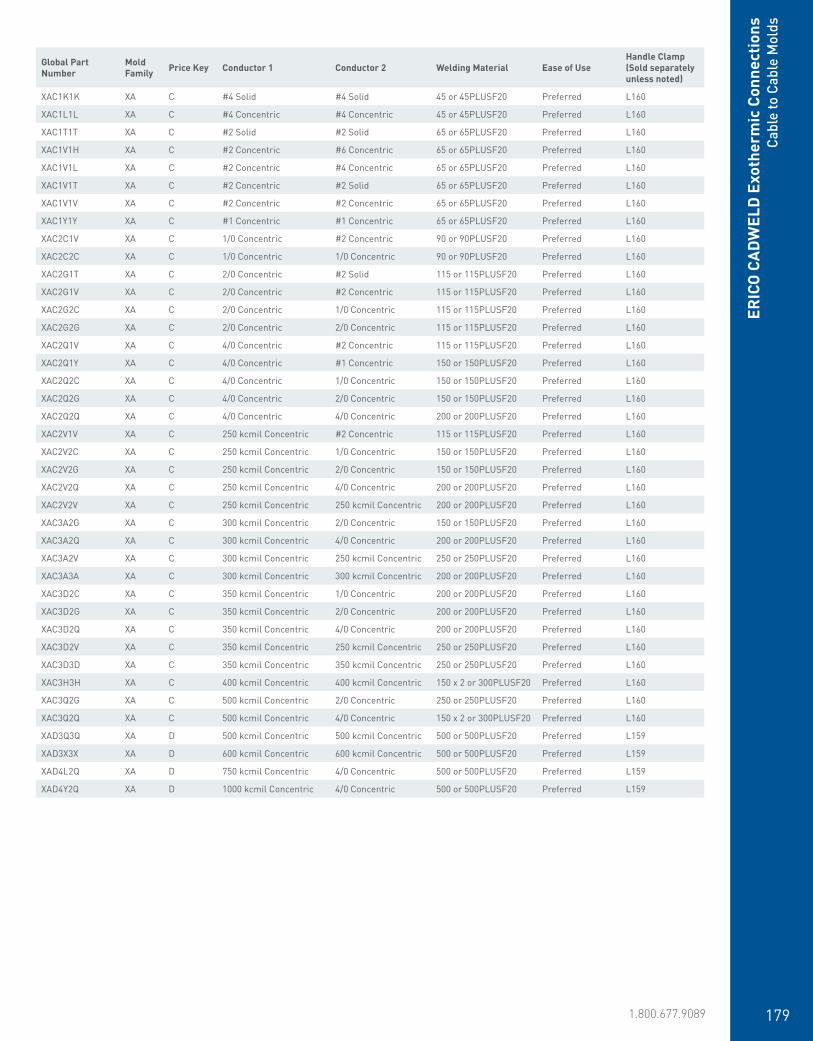
www.erico.pentair.com 1.800.677.9089 179
ERIC
O C
ADW
ELD
Exo
ther
mic
Con
nect
ions
Cabl
e to
Cab
le M
olds
XAC1K1K XA C #4 Solid #4 Solid 45 or 45PLUSF20 Preferred L160
XAC1L1L XA C #4 Concentric #4 Concentric 45 or 45PLUSF20 Preferred L160
XAC1T1T XA C #2 Solid #2 Solid 65 or 65PLUSF20 Preferred L160
XAC1V1H XA C #2 Concentric #6 Concentric 65 or 65PLUSF20 Preferred L160
XAC1V1L XA C #2 Concentric #4 Concentric 65 or 65PLUSF20 Preferred L160
XAC1V1T XA C #2 Concentric #2 Solid 65 or 65PLUSF20 Preferred L160
XAC1V1V XA C #2 Concentric #2 Concentric 65 or 65PLUSF20 Preferred L160
XAC1Y1Y XA C #1 Concentric #1 Concentric 65 or 65PLUSF20 Preferred L160
XAC2C1V XA C 1/0 Concentric #2 Concentric 90 or 90PLUSF20 Preferred L160
XAC2C2C XA C 1/0 Concentric 1/0 Concentric 90 or 90PLUSF20 Preferred L160
XAC2G1T XA C 2/0 Concentric #2 Solid 115 or 115PLUSF20 Preferred L160
XAC2G1V XA C 2/0 Concentric #2 Concentric 115 or 115PLUSF20 Preferred L160
XAC2G2C XA C 2/0 Concentric 1/0 Concentric 115 or 115PLUSF20 Preferred L160
XAC2G2G XA C 2/0 Concentric 2/0 Concentric 115 or 115PLUSF20 Preferred L160
XAC2Q1V XA C 4/0 Concentric #2 Concentric 115 or 115PLUSF20 Preferred L160
XAC2Q1Y XA C 4/0 Concentric #1 Concentric 150 or 150PLUSF20 Preferred L160
XAC2Q2C XA C 4/0 Concentric 1/0 Concentric 150 or 150PLUSF20 Preferred L160
XAC2Q2G XA C 4/0 Concentric 2/0 Concentric 150 or 150PLUSF20 Preferred L160
XAC2Q2Q XA C 4/0 Concentric 4/0 Concentric 200 or 200PLUSF20 Preferred L160
XAC2V1V XA C 250 kcmil Concentric #2 Concentric 115 or 115PLUSF20 Preferred L160
XAC2V2C XA C 250 kcmil Concentric 1/0 Concentric 150 or 150PLUSF20 Preferred L160
XAC2V2G XA C 250 kcmil Concentric 2/0 Concentric 150 or 150PLUSF20 Preferred L160
XAC2V2Q XA C 250 kcmil Concentric 4/0 Concentric 200 or 200PLUSF20 Preferred L160
XAC2V2V XA C 250 kcmil Concentric 250 kcmil Concentric 200 or 200PLUSF20 Preferred L160
XAC3A2G XA C 300 kcmil Concentric 2/0 Concentric 150 or 150PLUSF20 Preferred L160
XAC3A2Q XA C 300 kcmil Concentric 4/0 Concentric 200 or 200PLUSF20 Preferred L160
XAC3A2V XA C 300 kcmil Concentric 250 kcmil Concentric 250 or 250PLUSF20 Preferred L160
XAC3A3A XA C 300 kcmil Concentric 300 kcmil Concentric 200 or 200PLUSF20 Preferred L160
XAC3D2C XA C 350 kcmil Concentric 1/0 Concentric 200 or 200PLUSF20 Preferred L160
XAC3D2G XA C 350 kcmil Concentric 2/0 Concentric 200 or 200PLUSF20 Preferred L160
XAC3D2Q XA C 350 kcmil Concentric 4/0 Concentric 200 or 200PLUSF20 Preferred L160
XAC3D2V XA C 350 kcmil Concentric 250 kcmil Concentric 250 or 250PLUSF20 Preferred L160
XAC3D3D XA C 350 kcmil Concentric 350 kcmil Concentric 250 or 250PLUSF20 Preferred L160
XAC3H3H XA C 400 kcmil Concentric 400 kcmil Concentric 150 x 2 or 300PLUSF20 Preferred L160
XAC3Q2G XA C 500 kcmil Concentric 2/0 Concentric 250 or 250PLUSF20 Preferred L160
XAC3Q2Q XA C 500 kcmil Concentric 4/0 Concentric 150 x 2 or 300PLUSF20 Preferred L160
XAD3Q3Q XA D 500 kcmil Concentric 500 kcmil Concentric 500 or 500PLUSF20 Preferred L159
XAD3X3X XA D 600 kcmil Concentric 600 kcmil Concentric 500 or 500PLUSF20 Preferred L159
XAD4L2Q XA D 750 kcmil Concentric 4/0 Concentric 500 or 500PLUSF20 Preferred L159
XAD4Y2Q XA D 1000 kcmil Concentric 4/0 Concentric 500 or 500PLUSF20 Preferred L159
Global Part Number
Mold Family Price Key Conductor 1 Conductor 2 Welding Material Ease of Use
Handle Clamp (Sold separately unless noted)

www.erico.pentair.com180
Global Part Number
Mold Family
Price Key Conductor 1 Conductor 2 Welding Material Ease of Use
Handle Clamp (Sold separately unless noted)
XB32C2C XB 3 1/0 Concentric 1/0 Concentric 150 or 150PLUSF20 Easy L163
XB32G2G XB 3 2/0 Concentric 2/0 Concentric 200 or 200PLUSF20 Easy L163
XB32L2L XB 3 3/0 Concentric 3/0 Concentric 250 or 250PLUSF20 Easy L163
XB32Q2Q XB 3 4/0 Concentric 4/0 Concentric 250 or 250PLUSF20 Easy L163
XB32V2V XB 3 250 kcmil Concentric 250 kcmil Concentric 150 x 2 or 300PLUSF20 Easy L163
XB43D3D XB 4 350 kcmil Concentric 350 kcmil Concentric 500 or 500PLUSF20 Easy L164
XBC1K1K XB C #4 Solid #4 Solid 65 or 65PLUSF20 Easy L160
XBC1L1L XB C #4 Concentric #4 Concentric 65 or 65PLUSF20 Easy L160
XBC1T1T XB C #2 Solid #2 Solid 90 or 90PLUSF20 Easy L160
XBC1V1L XB C #2 Concentric #4 Concentric 65 or 65PLUSF20 Easy L160
XBC1V1V XB C #2 Concentric #2 Concentric 90 or 90PLUSF20 Easy L160
XBC1Y1Y XB C #1 Concentric #1 Concentric 115 or 115PLUSF20 Easy L160
XBC2C1V XB C 1/0 Concentric #2 Concentric 115 or 115PLUSF20 Easy L160
XBK3X3X XB K 600 kcmil Concentric 600 kcmil Concentric 500 x 2 or 1000PLUSF20 Easy Includes Frame w/Handles
XBK4L3Q XB K 750 kcmil Concentric 500 kcmil Concentric 500 x 2 or 1000PLUSF20 Easy Includes Frame w/Handles
XBK4L4L XB K 750 kcmil Concentric 750 kcmil Concentric 250 x 5 or 1250PLUSF20 Easy Includes Frame w/Handles
XBK4Y3Q XB K 1000 kcmil Concentric 500 kcmil Concentric 500 x 2 or 1000PLUSF20 Easy Includes Frame w/Handles
XBK4Y4Y XB K 1000 kcmil Concentric 1000 kcmil Concentric 500 x 3 or 1500PLUSF20 Easy Includes Frame w/Handles
XBM2C2C XB M 1/0 Concentric 1/0 Concentric 150 or 150PLUSF20 Easy Includes Frame w/Handles
XBM2G2G XB M 2/0 Concentric 2/0 Concentric 200 or 200PLUSF20 Easy Includes Frame w/Handles
XBM2L2L XB M 3/0 Concentric 3/0 Concentric 250 or 250PLUSF20 Easy Includes Frame w/Handles
XBM2Q2Q XB M 4/0 Concentric 4/0 Concentric 250 or 250PLUSF20 Easy Includes Frame w/Handles
XBM2V2V XB M 250 kcmil Concentric 250 kcmil Concentric 150 x 2 or 300PLUSF20 Easy Includes Frame w/Handles
XBP1G1G XB P #6 Solid #6 Solid 32 or 32PLUSF20 Easy Clamp Included
XBP1H1H XB P #6 Concentric #6 Concentric 45 or 45PLUSF20 Easy Clamp Included
XBQ2C2C XB Q 1/0 Concentric 1/0 Concentric 150 or 150PLUSF20 Easy L160
XBQ2G1V XB Q 2/0 Concentric #2 Concentric 150 or 150PLUSF20 Easy L160
XBQ2G2C XB Q 2/0 Concentric 1/0 Concentric 200 or 200PLUSF20 Easy L160
XBQ2G2G XB Q 2/0 Concentric 2/0 Concentric 200 or 200PLUSF20 Easy L160
XBQ2Q2C XB Q 4/0 Concentric 1/0 Concentric 200 or 200PLUSF20 Easy L160
XBQ2Q2G XB Q 4/0 Concentric 2/0 Concentric 200 or 200PLUSF20 Easy L160
XBQ2Q2Q XB Q 4/0 Concentric 4/0 Concentric 250 or 250PLUSF20 Easy L160
XBQ2V2G XB Q 250 kcmil Concentric 2/0 Concentric 250 or 250PLUSF20 Easy L160
XBQ2V2Q XB Q 250 kcmil Concentric 4/0 Concentric 150 x 2 or 300PLUSF20 Easy L160
XB Molds
ERICO
CADW
ELD Exotherm
ic ConnectionsCable to Cable M
olds

www.erico.pentair.com 1.800.677.9089 181
PG Molds
PT Molds
XBQ2V2V XB Q 250 kcmil Concentric 250 kcmil Concentric 150 x 2 or 300PLUSF20 Easy L160
XBV3A3A XB V 300 kcmil Concentric 300 kcmil Concentric 200 x 2 or 400PLUSF20 Easy Includes Frame w/Handles
XBV3D3D XB V 350 kcmil Concentric 350 kcmil Concentric 500 or 500PLUSF20 Easy Includes Frame w/Handles
XBV3H3H XB V 400 kcmil Concentric 400 kcmil Concentric 200 x 3 or 600PLUSF20 Easy Includes Frame w/Handles
XBV3Q3Q XB V 500 kcmil Concentric 500 kcmil Concentric 200 x 3 or 600PLUSF20 Easy Includes Frame w/Handles
Global Part Number
Mold Family Price Key Conductor 1 Conductor 2 Welding Material Ease of Use
Handle Clamp (Sold separately unless noted)
PGT08CU PG T #8 Solid #8 Solid 15 or 15PLUSF20 Easy Clamp Included
PGT10CU PG T #10 Solid #10 Solid 15 or 15PLUSF20 Easy Clamp Included
PGT1D1D PG T #8 Solid #8 Solid 15 or 15PLUSF20 Easy Clamp Included
PGT1G1G PG T #6 Solid #6 Solid 25 or 25PLUSF20 Easy Clamp Included
PGT1G1H PG T #6 Solid #6 Concentric 25 or 25PLUSF20 Easy Clamp Included
PGT1H1H PG T #6 Concentric #6 Concentric 25 or 25PLUSF20 Easy Clamp Included
PGT1K1K PG T #4 Solid #4 Solid 32 or 32PLUSF20 Easy Clamp Included
Global Part Number
Mold Family Price Key Conductor 1 Conductor 2 Welding Material Ease of Use
Handle Clamp (Sold separately unless noted)
PTC1D1D PT C #8 Solid #8 Solid 25 or 25PLUSF20 Preferred L160
PTC1G1G PT C #6 Solid #6 Solid 32 or 32PLUSF20 Preferred L160
PTC1H1H PT C #6 Concentric #6 Concentric 32 or 32PLUSF20 Preferred L160
PTC1K1K PT C #4 Solid #4 Solid 32 or 32PLUSF20 Preferred L160
PTC1L1D PT C #4 Concentric #8 Solid 32 or 32PLUSF20 Preferred L160
PTC1L1G PT C #4 Concentric #6 Solid 32 or 32PLUSF20 Preferred L160
PTC1L1H PT C #4 Concentric #6 Concentric 32 or 32PLUSF20 Preferred L160
PTC1L1L PT C #4 Concentric #4 Concentric 32 or 32PLUSF20 Preferred L160
PTC1T1D PT C #2 Solid #8 Solid 45 or 45PLUSF20 Preferred L160
PTC1T1G PT C #2 Solid #6 Solid 45 or 45PLUSF20 Preferred L160
PTC1T1H PT C #2 Solid #6 Concentric 45 or 45PLUSF20 Preferred L160
ERIC
O C
ADW
ELD
Exo
ther
mic
Con
nect
ions
Cabl
e to
Cab
le M
olds

www.erico.pentair.com182
PTC1T1K PT C #2 Solid #4 Solid 65 or 65PLUSF20 Preferred L160
PTC1T1L PT C #2 Solid #4 Concentric 65 or 65PLUSF20 Preferred L160
PTC1T1T PT C #2 Solid #2 Solid 65 or 65PLUSF20 Preferred L160
PTC1T1V PT C #2 Solid #2 Concentric 65 or 65PLUSF20 Preferred L160
PTC1V1D PT C #2 Concentric #8 Solid 45 or 45PLUSF20 Preferred L160
PTC1V1G PT C #2 Concentric #6 Solid 45 or 45PLUSF20 Preferred L160
PTC1V1H PT C #2 Concentric #6 Concentric 45 or 45PLUSF20 Preferred L160
PTC1V1K PT C #2 Concentric #4 Solid 65 or 65PLUSF20 Preferred L160
PTC1V1L PT C #2 Concentric #4 Concentric 65 or 65PLUSF20 Preferred L160
PTC1V1T PT C #2 Concentric #2 Solid 65 or 65PLUSF20 Preferred L160
PTC1V1V PT C #2 Concentric #2 Concentric 65 or 65PLUSF20 Preferred L160
PTC1Y1G PT C #1 Concentric #6 Solid 65 or 65PLUSF20 Preferred L160
PTC1Y1T PT C #1 Concentric #2 Solid 65 or 65PLUSF20 Preferred L160
PTC1Y1Y PT C #1 Concentric #1 Concentric 65 or 65PLUSF20 Preferred L160
PTC2C1D PT C 1/0 Concentric #8 Solid 65 or 65PLUSF20 Preferred L160
PTC2C1G PT C 1/0 Concentric #6 Solid 65 or 65PLUSF20 Preferred L160
PTC2C1H PT C 1/0 Concentric #6 Concentric 65 or 65PLUSF20 Preferred L160
PTC2C1L PT C 1/0 Concentric #4 Concentric 65 or 65PLUSF20 Preferred L160
PTC2C1T PT C 1/0 Concentric #2 Solid 65 or 65PLUSF20 Preferred L160
PTC2C1V PT C 1/0 Concentric #2 Concentric 65 or 65PLUSF20 Preferred L160
PTC2C1Y PT C 1/0 Concentric #1 Concentric 65 or 65PLUSF20 Preferred L160
PTC2C2C PT C 1/0 Concentric 1/0 Concentric 90 or 90PLUSF20 Preferred L160
PTC2G1D PT C 2/0 Concentric #8 Solid 90 or 90PLUSF20 Preferred L160
PTC2G1G PT C 2/0 Concentric #6 Solid 90 or 90PLUSF20 Preferred L160
PTC2G1H PT C 2/0 Concentric #6 Concentric 90 or 90PLUSF20 Preferred L160
PTC2G1K PT C 2/0 Concentric #4 Solid 65 or 65PLUSF20 Preferred L160
PTC2G1L PT C 2/0 Concentric #4 Concentric 90 or 90PLUSF20 Preferred L160
PTC2G1T PT C 2/0 Concentric #2 Solid 90 or 90PLUSF20 Preferred L160
PTC2G1V PT C 2/0 Concentric #2 Concentric 90 or 90PLUSF20 Preferred L160
PTC2G2C PT C 2/0 Concentric 1/0 Concentric 115 or 115PLUSF20 Preferred L160
PTC2G2G PT C 2/0 Concentric 2/0 Concentric 115 or 115PLUSF20 Preferred L160
PTC2Q1D PT C 4/0 Concentric #8 Solid 90 or 90PLUSF20 Preferred L160
PTC2Q1G PT C 4/0 Concentric #6 Solid 90 or 90PLUSF20 Preferred L160
PTC2Q1H PT C 4/0 Concentric #6 Concentric 90 or 90PLUSF20 Preferred L160
PTC2Q1K PT C 4/0 Concentric #4 Solid 150 or 150PLUSF20 Preferred L160
PTC2Q1L PT C 4/0 Concentric #4 Concentric 150 or 150PLUSF20 Preferred L160
PTC2Q1T PT C 4/0 Concentric #2 Solid 150 or 150PLUSF20 Preferred L160
PTC2Q1V PT C 4/0 Concentric #2 Concentric 150 or 150PLUSF20 Preferred L160
PTC2Q1Y PT C 4/0 Concentric #1 Concentric 150 or 150PLUSF20 Preferred L160
PTC2Q2C PT C 4/0 Concentric 1/0 Concentric 150 or 150PLUSF20 Preferred L160
PTC2Q2G PT C 4/0 Concentric 2/0 Concentric 150 or 150PLUSF20 Preferred L160
PTC2Q2Q PT C 4/0 Concentric 4/0 Concentric 200 or 200PLUSF20 Preferred L160
PTC2V1T PT C 250 kcmil Concentric #2 Solid 150 or 150PLUSF20 Preferred L160
PTC2V1V PT C 250 kcmil Concentric #2 Concentric 150 or 150PLUSF20 Preferred L160
PTC2V2C PT C 250 kcmil Concentric 1/0 Concentric 150 or 150PLUSF20 Preferred L160
PTC2V2G PT C 250 kcmil Concentric 2/0 Concentric 150 or 150PLUSF20 Preferred L160
PTC2V2Q PT C 250 kcmil Concentric 4/0 Concentric 200 or 200PLUSF20 Preferred L160
PTC2V2V PT C 250 kcmil Concentric 250 kcmil Concentric 250 or 250PLUSF20 Preferred L160
PTC3A2Q PT C 300 kcmil Concentric 4/0 Concentric 200 or 200PLUSF20 Preferred L160
PTC3A3A PT C 300 kcmil Concentric 300 kcmil Concentric 150 x 2 or 300PLUSF20 Preferred L160
PTC3D2Q PT C 350 kcmil Concentric 4/0 Concentric 200 or 200PLUSF20 Preferred L160
ERICO
CADW
ELD Exotherm
ic ConnectionsCable to Cable M
olds
Global Part Number
Mold Family Price Key Conductor 1 Conductor 2 Welding Material Ease of Use
Handle Clamp (Sold separately unless noted)

www.erico.pentair.com 1.800.677.9089 183
PTC3D2V PT C 350 kcmil Concentric 250 kcmil Concentric 250 or 250PLUSF20 Preferred L160
PTC3D3D PT C 350 kcmil Concentric 350 kcmil Concentric 150 x 2 or 300PLUSF20 Preferred L160
PTC3H2Q PT C 400 kcmil Concentric 4/0 Concentric 200 or 200PLUSF20 Preferred L160
PTC3Q2G PT C 500 kcmil Concentric 2/0 Concentric 150 or 150PLUSF20 Preferred L160
PTC3Q2Q PT C 500 kcmil Concentric 4/0 Concentric 200 or 200PLUSF20 Preferred L160
PTC3Q2V PT C 500 kcmil Concentric 250 kcmil Concentric 250 or 250PLUSF20 Preferred L160
PTC3Q3A PT C 500 kcmil Concentric 300 kcmil Concentric 150 x 2 or 300PLUSF20 Preferred L160
PTC3Q3D PT C 500 kcmil Concentric 350 kcmil Concentric 150 x 2 or 300PLUSF20 Preferred L160
PTC4L2Q PT C 750 kcmil Concentric 4/0 Concentric 250 or 250PLUSF20 Preferred L160
PTC4Y2Q PT C 1000 kcmil Concentric 4/0 Concentric 150 x 2 or 300PLUSF20 Preferred L160
PTC2Q2Q PT D 4/0 Concentric 4/0 Concentric 200 or 200PLUSF20 Preferred L159
PTD3H3H PT D 400 kcmil Concentric 400 kcmil Concentric 200 x 2 or 400PLUSF20 Preferred L159
PTD3Q3Q PT D 500 kcmil Concentric 500 kcmil Concentric 200 x 2 or 400PLUSF20 Preferred L159
PTF4L4L PT F 750 kcmil Concentric 750 kcmil Concentric 250 x 3 or 750PLUSF20 Preferred L159
PTF4Y4Y PT F 1000 kcmil Concentric 1000 kcmil Concen-tric
500 x 2 or 1000PLUSF20
Preferred L159
PH Molds
Global Part Number
Mold Family
Price Key Conductor 1 Conductor 2 Welding Material Ease of Use Handle Clamp (Sold
separately unless noted)
PHJ2Q2Q PH J 4/0 Concentric 4/0 Concentric 200 x 2 or 400PLUSF20 Difficult Include Frame & Requires L159
PHJ2V2Q PH J 250 kcmil Concentric 4/0 Concentric 200 x 2 or 400PLUSF20 Difficult Include Frame & Requires L159
PHJ2V2V PH J 250 kcmil Concentric 250 kcmil Concentric 200 x 2 or 400PLUSF20 Difficult Include Frame & Requires L159
PHJ3A3A PH J 300 kcmil Concentric 300 kcmil Concentric 200 x 2 or 400PLUSF20 Difficult Include Frame & Requires L159
PHJ3D2Q PH J 350 kcmil Concentric 4/0 Concentric 200 x 2 or 400PLUSF20 Difficult Include Frame & Requires L159
PHJ3D2V PH J 350 kcmil Concentric 250 kcmil Concentric 200 x 2 or 400PLUSF20 Difficult Include Frame & Requires L159
PHJ3Q2Q PH J 500 kcmil Concentric 4/0 Concentric 500 or 500PLUSF20 Difficult Include Frame & Requires L159
PHJ3Q3Q PH J 500 kcmil Concentric 500 kcmil Concentric 250 x 3 or 750PLUSF20 Difficult Include Frame & Requires L159
PHR1K1K PH R #4 Solid #4 Solid 65 or 65PLUSF20 Difficult L160
PHR1L1L PH R #4 Concentric #4 Concentric 65 or 65PLUSF20 Difficult L160
PHR1T1T PH R #2 Solid #2 Solid 115 or 115PLUSF20 Difficult L160
PHR1V1L PH R #2 Concentric #4 Concentric 90 or 90PLUSF20 Difficult L160
PHR1V1T PH R #2 Concentric #2 Solid 115 or 115PLUSF20 Difficult L160
PHR1V1V PH R #2 Concentric #2 Concentric 115 or 115PLUSF20 Difficult L160
PHR2C1T PH R 1/0 Concentric #2 Solid 115 or 115PLUSF20 Difficult L160
PHR2C1V PH R 1/0 Concentric #2 Concentric 115 or 115PLUSF20 Difficult L160
ERIC
O C
ADW
ELD
Exo
ther
mic
Con
nect
ions
Cabl
e to
Cab
le M
olds
Global Part Number
Mold Family Price Key Conductor 1 Conductor 2 Welding Material Ease of Use
Handle Clamp (Sold separately unless noted)

www.erico.pentair.com184
PHR2C2C PH R 1/0 Concentric 1/0 Concentric 150 or 150PLUSF20 Difficult L160
PHR2G1L PH R 2/0 Concentric #4 Concentric 115 or 115PLUSF20 Difficult L160
PHR2G1T PH R 2/0 Concentric #2 Solid 150 or 150PLUSF20 Difficult L160
PHR2G1V PH R 2/0 Concentric #2 Concentric 150 or 150PLUSF20 Difficult L160
PHR2G2C PH R 2/0 Concentric 1/0 Concentric 150 or 150PLUSF20 Difficult L160
PHR2G2G PH R 2/0 Concentric 2/0 Concentric 150 or 150PLUSF20 Difficult L160
PHR2Q1T PH R 4/0 Concentric #2 Solid 200 or 200PLUSF20 Difficult L160
PHR2Q1V PH R 4/0 Concentric #2 Concentric 200 or 200PLUSF20 Difficult L160
PHR2Q2C PH R 4/0 Concentric 1/0 Concentric 250 or 250PLUSF20 Difficult L160
PHR2Q2G PH R 4/0 Concentric 2/0 Concentric 250 or 250PLUSF20 Difficult L160
PHT1D1D PH T #8 Solid #8 Solid 25 or 25PLUSF20 Difficult Clamp Included
Cable to Ground Rod Splice
• Forms a permanent, low resistance connection
• Provides a molecular bond• ERICO CADWELD Exothermic Connections
are rated with the same current capacity as the conductor
• Portable installation equipment with no external source of power required
• Installers can be easily trained to make ERICO CADWELD Exothermic Connections
• Connections are visually inspected
Global Part Number
Mold Family
Price Key
Ground Rod Diameter (Nominal)
Ground Rod Diameter (Actual)
Ground Rod Type
Welding Material Required Ease of Use
Handle Clamp Required
Other Accessories Required
HDGBR12 GB R 3/8” 0.375” Steel 250 or 250PLUSF20 Preferred L160 B120
HDGBC14S GB C 1/2” 0.505” Steel 200 or 200PLUSF20 Preferred L160 B120
HDGBD16 GB D 5/8” 0.563” Copper-bonded 150 x 2 or 300PLUSF20 Preferred L159 B120
HDGBD31 GB D 5/8” 0.625” Steel 150 x 2 or 300PLUSF20 Preferred L159 B120
HDGBF18 GB F 3/4” 0.682” Copper-bonded 200 x 2 or 400PLUSF20 Preferred L159 B120
HDGBF22 GB F 1” 0.914” Copper-bonded 250 x 3 or 750PLUSF20 Preferred L159 B120
HDGBF33 GB F 3/4” 0.750” Steel 200 x 2 or 400PLUSF20 Preferred L159 B120
HDGBF37 GB F 1” 1.000” Steel 250 x 3 or 750PLUSF20 Preferred L159 B120
HDGBR15 GB R 1/2” 0.475” Copper-bonded 250 or 250PLUSF20 Preferred L160 B120
GB Molds
ERICO
CADW
ELD Exotherm
ic ConnectionsCable to Ground Rod Splice M
olds
Global Part Number
Mold Family
Price Key Conductor 1 Conductor 2 Welding Material Ease of Use Handle Clamp (Sold
separately unless noted)
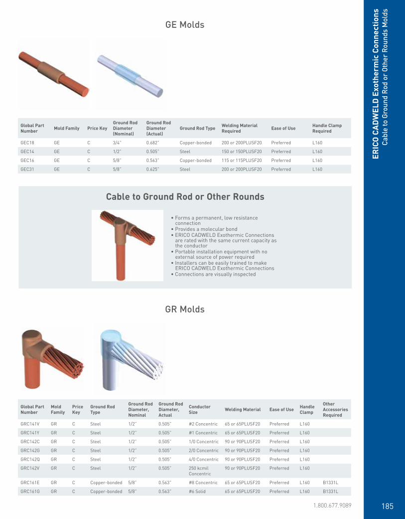
www.erico.pentair.com 1.800.677.9089 185
Cable to Ground Rod or Other Rounds
• Forms a permanent, low resistance connection
• Provides a molecular bond• ERICO CADWELD Exothermic Connections
are rated with the same current capacity as the conductor
• Portable installation equipment with no external source of power required
• Installers can be easily trained to make ERICO CADWELD Exothermic Connections
• Connections are visually inspected
GE Molds
GR Molds
Global Part Number Mold Family Price Key
Ground Rod Diameter (Nominal)
Ground Rod Diameter (Actual)
Ground Rod Type Welding Material Required Ease of Use Handle Clamp
Required
GEC18 GE C 3/4” 0.682” Copper-bonded 200 or 200PLUSF20 Preferred L160
GEC14 GE C 1/2” 0.505” Steel 150 or 150PLUSF20 Preferred L160
GEC16 GE C 5/8” 0.563” Copper-bonded 115 or 115PLUSF20 Preferred L160
GEC31 GE C 5/8” 0.625” Steel 200 or 200PLUSF20 Preferred L160
Global Part Number
Mold Family
Price Key
Ground Rod Type
Ground Rod Diameter, Nominal
Ground Rod Diameter, Actual
Conductor Size Welding Material Ease of Use Handle
Clamp
Other Accessories Required
GRC141V GR C Steel 1/2” 0.505” #2 Concentric 65 or 65PLUSF20 Preferred L160
GRC141Y GR C Steel 1/2” 0.505” #1 Concentric 65 or 65PLUSF20 Preferred L160
GRC142C GR C Steel 1/2” 0.505” 1/0 Concentric 90 or 90PLUSF20 Preferred L160
GRC142G GR C Steel 1/2” 0.505” 2/0 Concentric 90 or 90PLUSF20 Preferred L160
GRC142Q GR C Steel 1/2” 0.505” 4/0 Concentric 90 or 90PLUSF20 Preferred L160
GRC142V GR C Steel 1/2” 0.505” 250 kcmil Concentric
90 or 90PLUSF20 Preferred L160
GRC161E GR C Copper-bonded 5/8” 0.563” #8 Concentric 65 or 65PLUSF20 Preferred L160 B1331L
GRC161G GR C Copper-bonded 5/8” 0.563” #6 Solid 65 or 65PLUSF20 Preferred L160 B1331L
ERIC
O C
ADW
ELD
Exo
ther
mic
Con
nect
ions
Cabl
e to
Gro
und
Rod
or O
ther
Rou
nds
Mol
ds

www.erico.pentair.com186
GRC161H GR C Copper-bonded 5/8” 0.563” #6 Concentric 65 or 65PLUSF20 Preferred L160 B112
GRC161K GR C Copper-bonded 5/8” 0.563” #4 Solid 65 or 65PLUSF20 Preferred L160
GRC161L GR C Copper-bonded 5/8” 0.563” #4 Concentric 65 or 65PLUSF20 Preferred L160
GRC161T GR C Copper-bonded 5/8” 0.563” #2 Solid 65 or 65PLUSF20 Preferred L160
GRC161V GR C Copper-bonded 5/8” 0.563” #2 Concentric 65 or 65PLUSF20 Preferred L160
GRC161Y GR C Copper-bonded 5/8” 0.563” #1 Concentric 65 or 65PLUSF20 Preferred L160
GRC162C GR C Copper-bonded 5/8” 0.563” 1/0 Concentric 90 or 90PLUSF20 Preferred L160
GRC162G GR C Copper-bonded 5/8” 0.563” 2/0 Concentric 90 or 90PLUSF20 Preferred L160
GRC162Q GR C Copper-bonded 5/8” 0.563” 4/0 Concentric 90 or 90PLUSF20 Preferred L160
GRC162V GR C Copper-bonded 5/8” 0.563” 250 kcmil Concentric
90 or 90PLUSF20 Preferred L160
GRC163A GR C Copper-bonded 5/8” 0.563” 300 kcmil Concentric
115 or 115PLUSF20
Preferred L160
GRC163D GR C Copper-bonded 5/8” 0.563” 350 kcmil Concentric
115 or 115PLUSF20
Preferred L160
GRC163H GR C Copper-bonded 5/8” 0.563” 400 kcmil Concentric
150 or 150PLUSF20
Preferred L160
GRC163Q GR C Copper-bonded 5/8” 0.563” 500 kcmil Concentric
150 or 150PLUSF20
Preferred L160
GRC181G GR C Copper-bonded 3/4” 0.682” #6 Solid 90 or 90PLUSF20 Preferred L160 B1331L
GRC181H GR C Copper-bonded 3/4” 0.682” #6 Concentric 90 or 90PLUSF20 Preferred L160 B112
GRC181K GR C Copper-bonded 3/4” 0.682” #4 Solid 90 or 90PLUSF20 Preferred L160
GRC181L GR C Copper-bonded 3/4” 0.682” #4 Concentric 90 or 90PLUSF20 Preferred L160
GRC181T GR C Copper-bonded 3/4” 0.682” #2 Solid 90 or 90PLUSF20 Preferred L160
GRC181V GR C Copper-bonded 3/4” 0.682” #2 Concentric 90 or 90PLUSF20 Preferred L160
GRC181Y GR C Copper-bonded 3/4” 0.682” #1 Concentric 90 or 90PLUSF20 Preferred L160
GRC182C GR C Copper-bonded 3/4” 0.682” 1/0 Concentric 90 or 90PLUSF20 Preferred L160
GRC182G GR C Copper-bonded 3/4” 0.682” 2/0 Concentric 90 or 90PLUSF20 Preferred L160
GRC182Q GR C Copper-bonded 3/4” 0.682” 4/0 Concentric 90 or 90PLUSF20 Preferred L160
GRC182V GR C Copper-bonded 3/4” 0.682” 250 kcmil Concentric
90 or 90PLUSF20 Preferred L160
GRC183A GR C Copper-bonded 3/4” 0.682” 300 kcmil Concentric
115 or 115PLUSF20
Preferred L160
GRC183D GR C Copper-bonded 3/4” 0.682” 350 kcmil Concentric
115 or 115PLUSF20
Preferred L160
GRC183H GR C Copper-bonded 3/4” 0.682” 400 kcmil Concentric
150 or 150PLUSF20
Preferred L160
GRC183Q GR C Copper-bonded 3/4” 0.682” 500 kcmil Concentric
150 or 150PLUSF20
Preferred L160
GRC184L GR C Copper-bonded 3/4” 0.682” 750 kcmil Concentric
250 or 250PLUSF20
Preferred L160
GRC221T GR C Copper-bonded 1” 0.914” #2 Solid 150 or 150PLUSF20
Preferred L160
GRC221V GR C Copper-bonded 1” 0.914” #2 Concentric 150 or 150PLUSF20
Preferred L160
GRC222C GR C Copper-bonded 1” 0.914” 1/0 Concentric 150 or 150PLUSF20
Preferred L160
GRC222G GR C Copper-bonded 1” 0.914” 2/0 Concentric 150 or 150PLUSF20
Preferred L160
GRC222Q GR C Copper-bonded 1” 0.914” 4/0 Concentric 150 or 150PLUSF20
Preferred L160
GRC222V GR C Copper-bonded 1” 0.914” 250 kcmil Concentric
150 or 150PLUSF20
Preferred L160
GRC223D GR C Copper-bonded 1” 0.914” 350 kcmil Concentric
200 or 200PLUSF20
Preferred L160
GRC223Q GR C Copper-bonded 1” 0.914” 500 kcmil Concentric
200 or 200PLUSF20
Preferred L160
GRC224L GR C Copper-bonded 1” 0.914” 750 kcmil Concentric
150 x 2 or 300PLUSF20
Preferred L160
ERICO
CADW
ELD Exotherm
ic ConnectionsCable to Ground Rod or Other Rounds M
olds
Global Part Number
Mold Family
Price Key
Ground Rod Type
Ground Rod Diameter, Nominal
Ground Rod Diameter, Actual
Conductor Size Welding Material Ease of Use Handle
Clamp
Other Accessories Required
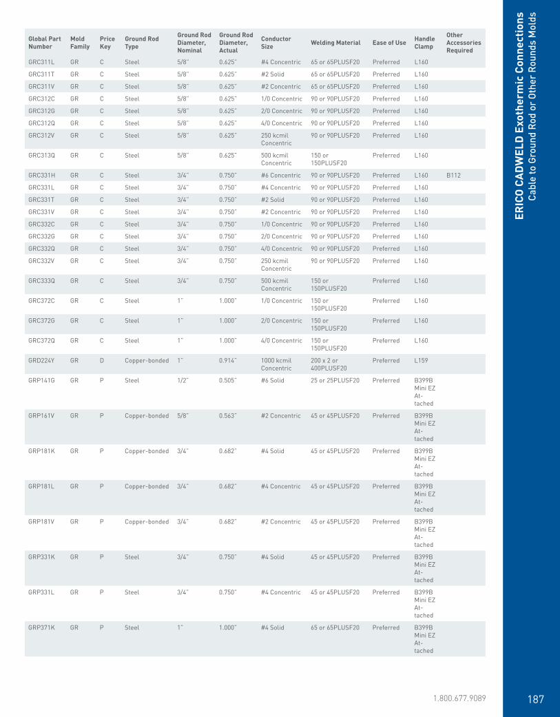
www.erico.pentair.com 1.800.677.9089 187
GRC311L GR C Steel 5/8” 0.625” #4 Concentric 65 or 65PLUSF20 Preferred L160
GRC311T GR C Steel 5/8” 0.625” #2 Solid 65 or 65PLUSF20 Preferred L160
GRC311V GR C Steel 5/8” 0.625” #2 Concentric 65 or 65PLUSF20 Preferred L160
GRC312C GR C Steel 5/8” 0.625” 1/0 Concentric 90 or 90PLUSF20 Preferred L160
GRC312G GR C Steel 5/8” 0.625” 2/0 Concentric 90 or 90PLUSF20 Preferred L160
GRC312Q GR C Steel 5/8” 0.625” 4/0 Concentric 90 or 90PLUSF20 Preferred L160
GRC312V GR C Steel 5/8” 0.625” 250 kcmil Concentric
90 or 90PLUSF20 Preferred L160
GRC313Q GR C Steel 5/8” 0.625” 500 kcmil Concentric
150 or 150PLUSF20
Preferred L160
GRC331H GR C Steel 3/4” 0.750” #6 Concentric 90 or 90PLUSF20 Preferred L160 B112
GRC331L GR C Steel 3/4” 0.750” #4 Concentric 90 or 90PLUSF20 Preferred L160
GRC331T GR C Steel 3/4” 0.750” #2 Solid 90 or 90PLUSF20 Preferred L160
GRC331V GR C Steel 3/4” 0.750” #2 Concentric 90 or 90PLUSF20 Preferred L160
GRC332C GR C Steel 3/4” 0.750” 1/0 Concentric 90 or 90PLUSF20 Preferred L160
GRC332G GR C Steel 3/4” 0.750” 2/0 Concentric 90 or 90PLUSF20 Preferred L160
GRC332Q GR C Steel 3/4” 0.750” 4/0 Concentric 90 or 90PLUSF20 Preferred L160
GRC332V GR C Steel 3/4” 0.750” 250 kcmil Concentric
90 or 90PLUSF20 Preferred L160
GRC333Q GR C Steel 3/4” 0.750” 500 kcmil Concentric
150 or 150PLUSF20
Preferred L160
GRC372C GR C Steel 1” 1.000” 1/0 Concentric 150 or 150PLUSF20
Preferred L160
GRC372G GR C Steel 1” 1.000” 2/0 Concentric 150 or 150PLUSF20
Preferred L160
GRC372Q GR C Steel 1” 1.000” 4/0 Concentric 150 or 150PLUSF20
Preferred L160
GRD224Y GR D Copper-bonded 1” 0.914” 1000 kcmil Concentric
200 x 2 or 400PLUSF20
Preferred L159
GRP141G GR P Steel 1/2” 0.505” #6 Solid 25 or 25PLUSF20 Preferred B399B Mini EZ At-tached
GRP161V GR P Copper-bonded 5/8” 0.563” #2 Concentric 45 or 45PLUSF20 Preferred B399B Mini EZ At-tached
GRP181K GR P Copper-bonded 3/4” 0.682” #4 Solid 45 or 45PLUSF20 Preferred B399B Mini EZ At-tached
GRP181L GR P Copper-bonded 3/4” 0.682” #4 Concentric 45 or 45PLUSF20 Preferred B399B Mini EZ At-tached
GRP181V GR P Copper-bonded 3/4” 0.682” #2 Concentric 45 or 45PLUSF20 Preferred B399B Mini EZ At-tached
GRP331K GR P Steel 3/4” 0.750” #4 Solid 45 or 45PLUSF20 Preferred B399B Mini EZ At-tached
GRP331L GR P Steel 3/4” 0.750” #4 Concentric 45 or 45PLUSF20 Preferred B399B Mini EZ At-tached
GRP371K GR P Steel 1” 1.000” #4 Solid 65 or 65PLUSF20 Preferred B399B Mini EZ At-tached
ERIC
O C
ADW
ELD
Exo
ther
mic
Con
nect
ions
Cabl
e to
Gro
und
Rod
or O
ther
Rou
nds
Mol
ds
Global Part Number
Mold Family
Price Key
Ground Rod Type
Ground Rod Diameter, Nominal
Ground Rod Diameter, Actual
Conductor Size Welding Material Ease of Use Handle
Clamp
Other Accessories Required

www.erico.pentair.com188
GRP371L GR P Steel 1” 1.000” #4 Concentric 65 or 65PLUSF20 Preferred B399B Mini EZ At-tached
GRT14A1G GR T Steel 1/2” 0.505” #6 Solid 25 or 25PLUSF20 Preferred B399A Mini EZ At-tached
GRT14A1H GR T Steel 1/2” 0.505” #6 Concentric 25 or 25PLUSF20 Preferred B399A Mini EZ At-tached
GRT14A1K GR T Steel 1/2” 0.505” #4 Solid 25 or 25PLUSF20 Preferred B399A Mini EZ At-tached
GRT14A1L GR T Steel 1/2” 0.505” #4 Concentric 25 or 25PLUSF20 Preferred B399A Mini EZ At-tached
GRT14A1T GR T Steel 1/2” 0.505” #2 Solid 32 or 32PLUSF20 Preferred B399A Mini EZ At-tached
GRT14A1V GR T Steel 1/2” 0.505” #2 Concentric 32 or 32PLUSF20 Preferred B399A Mini EZ At-tached
GRT14B1G GR T Copper-bonded 1/2” 0.562” #6 Solid 25 or 25PLUSF20 Preferred B399A Mini EZ At-tached
GRT14B1H GR T Copper-bonded 1/2” 0.562” #6 Concentric 25 or 25PLUSF20 Preferred B399A Mini EZ At-tached
GRT14C1G GR T Steel 1/2” 0.505” #6 Solid 25 or 25PLUSF20 Preferred B399A Mini EZ At-tached
GRT14C1H GR T Steel 1/2” 0.505” #6 Concentric 25 or 25PLUSF20 Preferred B399A Mini EZ At-tached
GRT14C1K GR T Steel 1/2” 0.505” #4 Solid 25 or 25PLUSF20 Preferred B399A Mini EZ At-tached
GRT14C1L GR T Steel 1/2” 0.505” #4 Concentric 25 or 25PLUSF20 Preferred B399A Mini EZ At-tached
GRT14C1T GR T Steel 1/2” 0.505” #2 Solid 32 or 32PLUSF20 Preferred B399A Mini EZ At-tached
GRT14C1V GR T Steel 1/2” 0.500” #2 Concentric 32 or 32PLUSF20 Preferred B399A Mini EZ At-tached
ERICO
CADW
ELD Exotherm
ic ConnectionsCable to Ground Rod or Other Rounds M
olds
Global Part Number
Mold Family
Price Key
Ground Rod Type
Ground Rod Diameter, Nominal
Ground Rod Diameter, Actual
Conductor Size Welding Material Ease of Use Handle
Clamp
Other Accessories Required
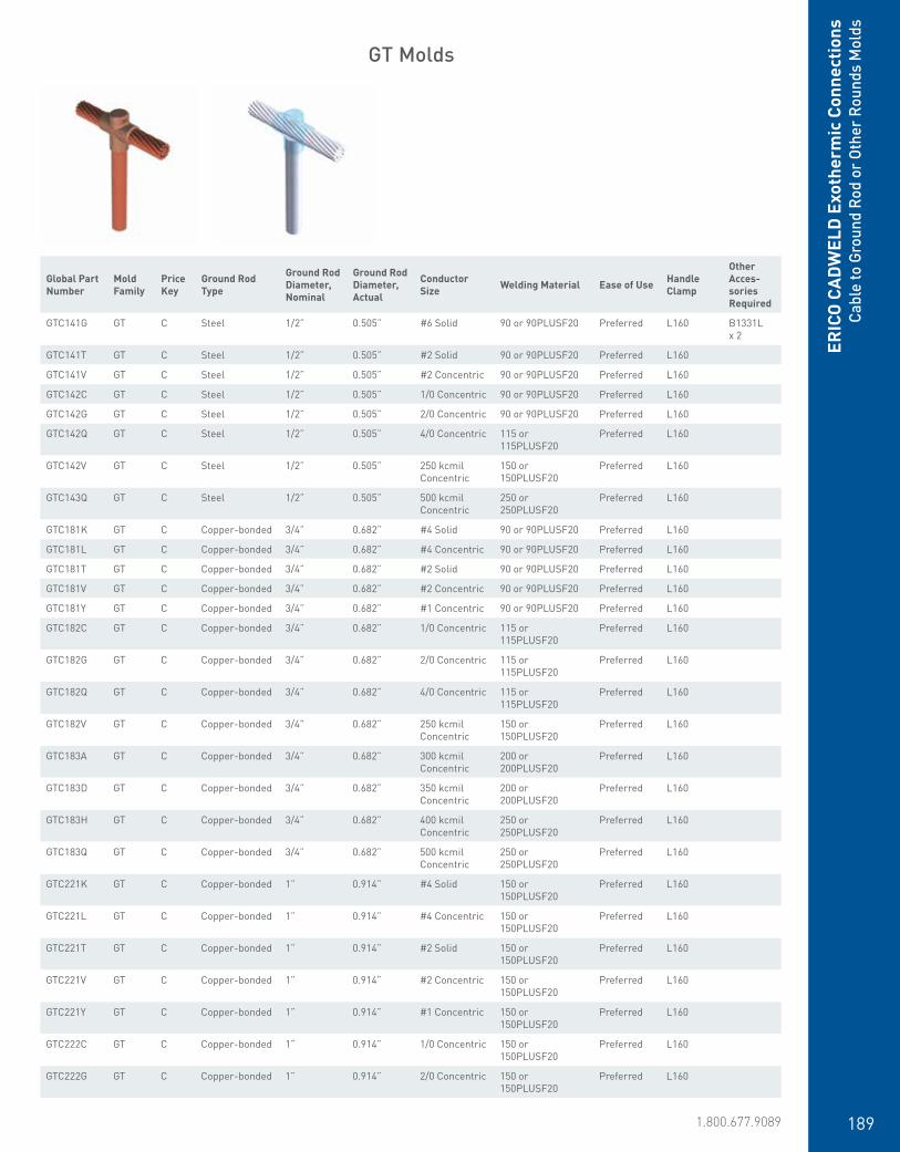
www.erico.pentair.com 1.800.677.9089 189
Global Part Number
Mold Family
Price Key
Ground Rod Type
Ground Rod Diameter, Nominal
Ground Rod Diameter, Actual
Conductor Size Welding Material Ease of Use Handle
Clamp
Other Acces-sories Required
GTC141G GT C Steel 1/2” 0.505” #6 Solid 90 or 90PLUSF20 Preferred L160 B1331L x 2
GTC141T GT C Steel 1/2” 0.505” #2 Solid 90 or 90PLUSF20 Preferred L160
GTC141V GT C Steel 1/2” 0.505” #2 Concentric 90 or 90PLUSF20 Preferred L160
GTC142C GT C Steel 1/2” 0.505” 1/0 Concentric 90 or 90PLUSF20 Preferred L160
GTC142G GT C Steel 1/2” 0.505” 2/0 Concentric 90 or 90PLUSF20 Preferred L160
GTC142Q GT C Steel 1/2” 0.505” 4/0 Concentric 115 or 115PLUSF20
Preferred L160
GTC142V GT C Steel 1/2” 0.505” 250 kcmil Concentric
150 or 150PLUSF20
Preferred L160
GTC143Q GT C Steel 1/2” 0.505” 500 kcmil Concentric
250 or 250PLUSF20
Preferred L160
GTC181K GT C Copper-bonded 3/4” 0.682” #4 Solid 90 or 90PLUSF20 Preferred L160
GTC181L GT C Copper-bonded 3/4” 0.682” #4 Concentric 90 or 90PLUSF20 Preferred L160
GTC181T GT C Copper-bonded 3/4” 0.682” #2 Solid 90 or 90PLUSF20 Preferred L160
GTC181V GT C Copper-bonded 3/4” 0.682” #2 Concentric 90 or 90PLUSF20 Preferred L160
GTC181Y GT C Copper-bonded 3/4” 0.682” #1 Concentric 90 or 90PLUSF20 Preferred L160
GTC182C GT C Copper-bonded 3/4” 0.682” 1/0 Concentric 115 or 115PLUSF20
Preferred L160
GTC182G GT C Copper-bonded 3/4” 0.682” 2/0 Concentric 115 or 115PLUSF20
Preferred L160
GTC182Q GT C Copper-bonded 3/4” 0.682” 4/0 Concentric 115 or 115PLUSF20
Preferred L160
GTC182V GT C Copper-bonded 3/4” 0.682” 250 kcmil Concentric
150 or 150PLUSF20
Preferred L160
GTC183A GT C Copper-bonded 3/4” 0.682” 300 kcmil Concentric
200 or 200PLUSF20
Preferred L160
GTC183D GT C Copper-bonded 3/4” 0.682” 350 kcmil Concentric
200 or 200PLUSF20
Preferred L160
GTC183H GT C Copper-bonded 3/4” 0.682” 400 kcmil Concentric
250 or 250PLUSF20
Preferred L160
GTC183Q GT C Copper-bonded 3/4” 0.682” 500 kcmil Concentric
250 or 250PLUSF20
Preferred L160
GTC221K GT C Copper-bonded 1” 0.914” #4 Solid 150 or 150PLUSF20
Preferred L160
GTC221L GT C Copper-bonded 1” 0.914” #4 Concentric 150 or 150PLUSF20
Preferred L160
GTC221T GT C Copper-bonded 1” 0.914” #2 Solid 150 or 150PLUSF20
Preferred L160
GTC221V GT C Copper-bonded 1” 0.914” #2 Concentric 150 or 150PLUSF20
Preferred L160
GTC221Y GT C Copper-bonded 1” 0.914” #1 Concentric 150 or 150PLUSF20
Preferred L160
GTC222C GT C Copper-bonded 1” 0.914” 1/0 Concentric 150 or 150PLUSF20
Preferred L160
GTC222G GT C Copper-bonded 1” 0.914” 2/0 Concentric 150 or 150PLUSF20
Preferred L160
GT Molds
ERIC
O C
ADW
ELD
Exo
ther
mic
Con
nect
ions
Cabl
e to
Gro
und
Rod
or O
ther
Rou
nds
Mol
ds

www.erico.pentair.com190
GTC222Q GT C Copper-bonded 1” 0.914” 4/0 Concentric 150 or 150PLUSF20
Preferred L160
GTC222V GT C Copper-bonded 1” 0.914” 250 kcmil Concentric
200 or 200PLUSF20
Preferred L160
GTC223D GT C Copper-bonded 1” 0.914” 350 kcmil Concentric
200 or 200PLUSF20
Preferred L160
GTC223H GT C Copper-bonded 1” 0.914” 400 kcmil Concentric
200 or 200PLUSF20
Preferred L160
GTC223Q GT C Copper-bonded 1” 0.914” 500 kcmil Concentric
250 or 250PLUSF20
Preferred L160
GTC311L GT C Steel 5/8” 0.625” #4 Concentric 90 or 90PLUSF20 Preferred L160
GTC311T GT C Steel 5/8” 0.625” #2 Solid 90 or 90PLUSF20 Preferred L160
GTC311V GT C Steel 5/8” 0.625” #2 Concentric 90 or 90PLUSF20 Preferred L160
GTC311Y GT C Steel 5/8” 0.625” #1 Concentric 90 or 90PLUSF20 Preferred L160
GTC312C GT C Steel 5/8” 0.625” 1/0 Concentric 90 or 90PLUSF20 Preferred L160
GTC312G GT C Steel 5/8” 0.625” 2/0 Concentric 115 or 115PLUSF20
Preferred L160
GTC312Q GT C Steel 5/8” 0.625” 4/0 Concentric 115 or 115PLUSF20
Preferred L160
GTC312V GT C Steel 5/8” 0.625” 250 kcmil Concentric
150 or 150PLUSF20
Preferred L160
GTC313A GT C Steel 5/8” 0.625” 300 kcmil Concentric
200 or 200PLUSF20
Preferred L160
GTC313D GT C Steel 5/8” 0.625” 350 kcmil Concentric
200 or 200PLUSF20
Preferred L160
GTC313H GT C Steel 5/8” 0.625” 400 kcmil Concentric
250 or 250PLUSF20
Preferred L160
GTC313Q GT C Steel 5/8” 0.625” 500 kcmil Concentric
250 or 250PLUSF20
Preferred L160
GTC331T GT C Steel 3/4” 0.750” #2 Solid 90 or 90PLUSF20 Preferred L160
GTC331Y GT C Steel 3/4” 0.750” #1 Concentric 90 or 90PLUSF20 Preferred L160
GTC333H GT C Steel 3/4” 0.750” 400 kcmil Concentric
250 or 250PLUSF20
Preferred L160
GTC331V GT C Steel 3/4” 0.750” #2 Concentric 90 or 90PLUSF20 Preferred L160
GTC332C GT C Steel 3/4” 0.750” 1/0 Concentric 115 or 115PLUSF20
Preferred L160
GTC332G GT C Steel 3/4” 0.750” 2/0 Concentric 115 or 115PLUSF20
Preferred L160
GTC332Q GT C Steel 3/4” 0.750” 4/0 Concentric 115 or 115PLUSF20
Preferred L160
GTC332V GT C Steel 3/4” 0.750” 250 kcmil Concentric
150 or 150PLUSF20
Preferred L160
GTC333A GT C Steel 3/4” 0.750” 300 kcmil Concentric
200 or 200PLUSF20
Preferred L160
GTC333D GT C Steel 3/4” 0.750” 350 kcmil Concentric
200 or 200PLUSF20
Preferred L160
GTC333Q GT C Steel 3/4” 0.750” 500 kcmil Concentric
250 or 250PLUSF20
Preferred L160
GTC371L GT C Steel 1” 1.000” #4 Concentric 150 or 150PLUSF20
Preferred L160
GTC371V GT C Steel 1” 1.000” #2 Concentric 150 or 150PLUSF20
Preferred L160
GTC372C GT C Steel 1” 1.000” 1/0 Concentric 150 or 150PLUSF20
Preferred L160
GTC372G GT C Steel 1” 1.000” 2/0 Concentric 150 or 150PLUSF20
Preferred L160
GTC372Q GT C Steel 1” 1.000” 4/0 Concentric 150 or 150PLUSF20
Preferred L160
GTC372V GT C Steel 1” 1.000” 250 kcmil Concentric
200 or 200PLUSF20
Preferred L160
ERICO
CADW
ELD Exotherm
ic ConnectionsCable to Ground Rod or Other Rounds M
olds
Global Part Number
Mold Family
Price Key
Ground Rod Type
Ground Rod Diameter, Nominal
Ground Rod Diameter, Actual
Conductor Size Welding Material Ease of Use Handle
Clamp
Other Acces-sories Required

www.erico.pentair.com 1.800.677.9089 191
GTC373Q GT C Steel 1” 1.000” 500 kcmil Concentric
250 or 250PLUSF20
Preferred L160
GTD164L GT D Copper-bonded 5/8” 0.563” 750 kcmil Concentric
200 x 2 or 400PLUSF20
Preferred L159
GTD184L GT D Copper-bonded 3/4” 0.682” 750 kcmil Concentric
200 x 2 or 400PLUSF20
Preferred L159
GTD184Y GT D Copper-bonded 3/4” 0.682” 1000 kcmil Concentric
500 or 500PLUSF20
Preferred L159
GTD224L GT D Copper-bonded 1” 0.914” 750 kcmil Concentric
500 or 500PLUSF20
Preferred L159
GTD224Y GT D Copper-bonded 1” 0.914” 1000 kcmil Concentric
500 or 500PLUSF20
Preferred L159
GTD374Y GT D Steel 1” 1.000” 1000 kcmil Concentric
500 or 500PLUSF20
Preferred L159
GTP161T GT P Copper-bonded 5/8” 0.563” #2 Solid 45 or 45PLUSF20 Preferred B399B Mini EZ Attached
GTP161V GT P Copper-bonded 5/8” 0.563” #2 Concentric 65 or 65PLUSF20 Preferred B399B Mini EZ Attached
GTP181G GT P Copper-bonded 3/4” 0.682” #6 Solid 45 or 45PLUSF20 Preferred B399B Mini EZ Attached
GTP181H GT P Copper-bonded 3/4” 0.682” #6 Concentric 45 or 45PLUSF20 Preferred B399B Mini EZ Attached
GTP181K GT P Copper-bonded 3/4” 0.682” #4 Solid 65 or 65PLUSF20 Preferred B399B Mini EZ Attached
GTP181L GT P Copper-bonded 3/4” 0.682” #4 Concentric 65 or 65PLUSF20 Preferred B399B Mini EZ Attached
GTP181T GT P Copper-bonded 3/4” 0.682” #2 Solid 65 or 65PLUSF20 Preferred B399B Mini EZ Attached
GTP181V GT P Copper-bonded 3/4” 0.682” #2 Concentric 65 or 65PLUSF20 Preferred B399B Mini EZ Attached
GTP331G GT P Steel 3/4” 0.750” #6 Solid 45 or 45PLUSF20 Preferred B399B Mini EZ Attached
GTP331H GT P Steel 3/4” 0.750” #6 Concentric 45 or 45PLUSF20 Preferred B399B Mini EZ Attached
GTP331K GT P Steel 3/4” 0.750” #4 Solid 65 or 65PLUSF20 Preferred B399B Mini EZ Attached
GTP331L GT P Steel 3/4” 0.750” #4 Concentric 65 or 65PLUSF20 Preferred B399B Mini EZ Attached
GTT14A1A GT T Steel 1/2” 0.505” #10 Solid 32 or 32PLUSF20 Preferred B399A Mini EZ Attached
GTT14A1G GT T Steel 1/2” 0.505” #6 Solid 32 or 32PLUSF20 Preferred B399A Mini EZ Attached
GTT14A1H GT T Steel 1/2” 0.505” #6 Concentric 32 or 32PLUSF20 Preferred B399A Mini EZ Attached
GTT14A1K GT T Steel 1/2” 0.505” #4 Solid 32 or 32PLUSF20 Preferred B399A Mini EZ Attached
GTT14A1L GT T Steel 1/2” 0.505” #4 Concentric 32 or 32PLUSF20 Preferred B399A Mini EZ Attached
ERIC
O C
ADW
ELD
Exo
ther
mic
Con
nect
ions
Cabl
e to
Gro
und
Rod
or O
ther
Rou
nds
Mol
ds
Global Part Number
Mold Family
Price Key
Ground Rod Type
Ground Rod Diameter, Nominal
Ground Rod Diameter, Actual
Conductor Size Welding Material Ease of Use Handle
Clamp
Other Acces-sories Required

www.erico.pentair.com192
GTT14B1H GT T Copper-bonded 1/2” 0.562” #6 Concentric 32 or 32PLUSF20 Preferred B399A Mini EZ Attached
GTT14C1G GT T Steel 1/2” 0.505” #6 Solid 32 or 32PLUSF20 Preferred B399A Mini EZ Attached
GTT14C1H GT T Steel 1/2” 0.505” #6 Concentric 32 or 32PLUSF20 Preferred B399A Mini EZ Attached
GTT14C1K GT T Steel 1/2” 0.505” #4 Solid 32 or 32PLUSF20 Preferred B399A Mini EZ Attached
GTT14C1L GT T Steel 1/2” 0.505” #4 Concentric 32 or 32PLUSF20 Preferred B399A Mini EZ Attached
GTT161G GT T Copper-bonded 5/8” 0.563” #6 Solid 32 or 32PLUSF20 Preferred B399A Mini EZ Attached
GTT161H GT T Copper-bonded 5/8” 0.563” #6 Concentric 32 or 32PLUSF20 Preferred B399A Mini EZ Attached
GTT161K GT T Copper-bonded 5/8” 0.563” #4 Solid 32 or 32PLUSF20 Preferred B399A Mini EZ Attached
GTT161L GT T Copper-bonded 5/8” 0.563” #4 Concentric 32 or 32PLUSF20 Preferred B399A Mini EZ Attached
GTT311G GT T Steel 5/8” 0.625” #6 Solid 32 or 32PLUSF20 Preferred B399A Mini EZ Attached
GTT311H GT T Steel 5/8” 0.625” #6 Concentric 32 or 32PLUSF20 Preferred B399A Mini EZ Attached
GTT311K GT T Steel 5/8” 0.625” #4 Solid 32 or 32PLUSF20 Preferred B399A Mini EZ Attached
GTT311L GT T Steel 5/8” 0.625” #4 Concentric 32 or 32PLUSF20 Preferred B399A Mini EZ Attached
ERICO
CADW
ELD Exotherm
ic ConnectionsCable to Ground Rod or Other Rounds M
olds
Global Part Number
Mold Family
Price Key
Ground Rod Type
Ground Rod Diameter, Nominal
Ground Rod Diameter, Actual
Conductor Size Welding Material Ease of Use Handle
Clamp
Other Acces-sories Required

www.erico.pentair.com 1.800.677.9089 193
Global Part Number
Mold Family
Price Key
Ground Rod Type
Ground Rod Diameter, Nominal
Ground Rod Diameter, Actual
Conductor Size Welding Material Ease of Use Handle
Clamp
Other Accessories Required
GYE141V GY E Steel 1/2” 0.505” #2 Concentric 90 or 90PLUSF20 Preferred L160
GYE142C GY E Steel 1/2” 0.505” 1/0 Concentric 115 or 115PLUSF20
Preferred L160
GYE142G GY E Steel 1/2” 0.505” 2/0 Concentric 115 or 115PLUSF20
Preferred L160
GYE142L GY E Steel 1/2” 0.505” 3/0 Concentric 150 or 150PLUSF20
Preferred L160
GYE142Q GY E Steel 1/2” 0.505” 4/0 Concentric 150 or 150PLUSF20
Preferred L160
GYE142V GY E Steel 1/2” 0.505” 250 kcmil Concentric
150 or 150PLUSF20
Preferred L160
GYE161G GY E Copper-bonded 5/8” 0.563” #6 Solid 90 or 90PLUSF20 Preferred L160 B1331L x 2
GYE161H GY E Copper-bonded 5/8” 0.563” #6 Concentric 90 or 90PLUSF20 Preferred L160 B112 x 2
GYE161K GY E Copper-bonded 5/8” 0.563” #4 Solid 90 or 90PLUSF20 Preferred L160
GYE161L GY E Copper-bonded 5/8” 0.563” #4 Concentric 90 or 90PLUSF20 Preferred L160
GYE161Q GY E Copper-bonded 5/8” 0.563” #3 Concentric 90 or 90PLUSF20 Preferred L160
GYE161T GY E Copper-bonded 5/8” 0.563” #2 Solid 90 or 90PLUSF20 Preferred L160
GYE161V GY E Copper-bonded 5/8” 0.563” #2 Concentric 90 or 90PLUSF20 Preferred L160
GYE162C GY E Copper-bonded 5/8” 0.563” 1/0 Concentric 115 or 115PLUSF20
Preferred L160
GYE162G GY E Copper-bonded 5/8” 0.563” 2/0 Concentric 115 or 115PLUSF20
Preferred L160
GYE162Q GY E Copper-bonded 5/8” 0.563” 4/0 Concentric 150 or 150PLUSF20
Preferred L160
GYE162V GY E Copper-bonded 5/8” 0.563” 250 kcmil Concentric
150 or 150PLUSF20
Preferred L160
GYE163A GY E Copper-bonded 5/8” 0.563” 300 kcmil Concentric
200 or 200PLUSF20
Preferred L160
GYE163D GY E Copper-bonded 5/8” 0.563” 350 kcmil Concentric
250 or 250PLUSF20
Preferred L160
GYE181G GY E Copper-bonded 3/4” 0.682” #6 Solid 90 or 90PLUSF20 Preferred L160 B1331L x 2
GYE181H GY E Copper-bonded 3/4” 0.682” #6 Concentric 90 or 90PLUSF20 Preferred L160 B112 x 2
GYE181K GY E Copper-bonded 3/4” 0.682” #4 Solid 90 or 90PLUSF20 Preferred L160
GYE181L GY E Copper-bonded 3/4” 0.682” #4 Concentric 90 or 90PLUSF20 Preferred L160
GYE181T GY E Copper-bonded 3/4” 0.682” #2 Solid 90 or 90PLUSF20 Preferred L160
GYE181V GY E Copper-bonded 3/4” 0.682” #2 Concentric 90 or 90PLUSF20 Preferred L160
GYE181Y GY E Copper-bonded 3/4” 0.682” #1 Concentric 115 or 115PLUSF20
Preferred L160
GYE182C GY E Copper-bonded 3/4” 0.682” 1/0 Concentric 115 or 115PLUSF20
Preferred L160
GYE182G GY E Copper-bonded 3/4” 0.682” 2/0 Concentric 115 or 115PLUSF20
Preferred L160
GYE332V GY E Steel 3/4” 0.750” 250 kcmil Concentric
200 or 200PLUSF20
Preferred L160
GYE372G GY E Steel 1” 1.000” 2/0 Concentric 115 or 115PLUSF20
Preferred L160
GY Molds
ERIC
O C
ADW
ELD
Exo
ther
mic
Con
nect
ions
Cabl
e to
Gro
und
Rod
or O
ther
Rou
nds
Mol
ds

www.erico.pentair.com194
ERICO
CADW
ELD Exotherm
ic Connections
GYE372Q GY E Steel 1” 1.000” 4/0 Concentric 150 or 150PLUSF20
Preferred L160
GYE372V GY E Steel 1” 1.000” 250 kcmil Concentric
200 or 200PLUSF20
Preferred L160
GYF163Q GY F Copper-bonded 5/8” 0.563” 500 kcmil Concentric
200 x 2 or 400PLUSF20
Preferred L159
GYF183Q GY F Copper-bonded 3/4” 0.682” 500 kcmil Concentric
500 or 500PLUSF20
Preferred L159
GYF313H GY F Steel 5/8” 0.625” 400 kcmil Concentric
200 x 2 or 400PLUSF20
Preferred L159
GYF313Q GY F Steel 5/8” 0.625” 500 kcmil Concentric
200 x 2 or 400PLUSF20
Preferred L159
GYF333Q GY F Steel 3/4” 0.750” 500 kcmil Concentric
500 or 500PLUSF20
Preferred L159
GYJ163H GY J Copper-bonded 5/8” 0.563” 400 kcmil Concentric
150 x 2 or 300PLUSF20
Preferred L159
GYJ163Q GY J Copper-bonded 5/8” 0.563” 500 kcmil Concentric
200 x 2 or 400PLUSF20
Preferred L159
GYJ164L GY J Copper-bonded 5/8” 0.563” 750 kcmil Concentric
500 or 500PLUSF20
Preferred L159
GYJ183D GY J Copper-bonded 3/4” 0.682” 350 kcmil Concentric
150 x 2 or 300PLUSF20
Preferred L159
GYJ183H GY J Copper-bonded 3/4” 0.682” 400 kcmil Concentric
500 or 500PLUSF20
Preferred L159
GYJ183Q GY J Copper-bonded 3/4” 0.682” 500 kcmil Concentric
500 or 500PLUSF20
Preferred L159
GYJ184L GY J Copper-bonded 3/4” 0.682” 750 kcmil Concentric
500 or 500PLUSF20
Preferred L159
GYJ223D GY J Copper-bonded 1” 0.914” 350 kcmil Concentric
150 x 2 or 300PLUSF20
Preferred L159
GYJ223Q GY J Copper-bonded 1” 0.914” 500 kcmil Concentric
500 or 500PLUSF20
Preferred L159
GYE182Q GY E Copper-bonded 3/4” 0.682” 4/0 Concentric 150 or 150PLUSF20
Preferred L160
GYE182V GY E Copper-bonded 3/4” 0.682” 250 kcmil Concentric
200 or 200PLUSF20
Preferred L160
GYE189B GY E Copper-bonded 3/4” 0.682” 7/#8 Copper-weld
115 or 115PLUSF20
Preferred L160
GYE222C GY E Copper-bonded 1” 0.914” 1/0 Concentric 115 or 115PLUSF20
Preferred L160
GYE222G GY E Copper-bonded 1” 0.914” 2/0 Concentric 115 or 115PLUSF20
Preferred L160
GYE222Q GY E Copper-bonded 1” 0.914” 4/0 Concentric 150 or 150PLUSF20
Preferred L160
GYE222V GY E Copper-bonded 1” 0.914” 250 kcmil Concentric
200 or 200PLUSF20
Preferred L160
GYE223D GY E Copper-bonded 1” 0.914” 350 kcmil Concentric
150 x 2 or 300PLUSF20
Preferred L160
GYE311T GY E Steel 5/8” 0.625” #2 Solid 90 or 90PLUSF20 Preferred L160
GYE311V GY E Steel 5/8” 0.625” #2 Concentric 90 or 90PLUSF20 Preferred L160
GYE312C GY E Steel 5/8” 0.625” 1/0 Concentric 115 or 115PLUSF20
Preferred L160
GYE312G GY E Steel 5/8” 0.625” 2/0 Concentric 115 or 115PLUSF20
Preferred L160
GYE312Q GY E Steel 5/8” 0.625” 4/0 Concentric 150 or 150PLUSF20
Preferred L160
GYE312V GY E Steel 5/8” 0.625” 250 kcmil Concentric
150 or 150PLUSF20
Preferred L160
GYE331T GY E Steel 3/4” 0.750” #2 Solid 90 or 90PLUSF20 Preferred L160
GYE331V GY E Steel 3/4” 0.750” #2 Concentric 90 or 90PLUSF20 Preferred L160
GYE332C GY E Steel 3/4” 0.750” 1/0 Concentric 115 or 115PLUSF20
Preferred L160
Cable to Ground Rod or Other Rounds Molds
Global Part Number
Mold Family
Price Key
Ground Rod Type
Ground Rod Diameter, Nominal
Ground Rod Diameter, Actual
Conductor Size Welding Material Ease of Use Handle
Clamp
Other Accessories Required

www.erico.pentair.com 1.800.677.9089 195
ERIC
O C
ADW
ELD
Exo
ther
mic
Con
nect
ions
GYE332G GY E Steel 3/4” 0.750” 2/0 Concentric 115 or 115PLUSF20
Preferred L160
GYE332Q GY E Steel 3/4” 0.750” 4/0 Concentric 150 or 150PLUSF20
Preferred L160
GYJ224L GY J Copper-bonded 1” 0.914” 750 kcmil Concentric
500 or 500PLUSF20
Preferred L159
GYJ313Q GY J Steel 5/8” 0.625” 500 kcmil Concentric
200 x 2 or 400PLUSF20
Preferred L159
GYJ333D GY J Steel 3/4” 0.750” 350 kcmil Concentric
150 x 2 or 300PLUSF20
Preferred L159
GYJ333Q GY J Steel 3/4” 0.750” 500 kcmil Concentric
500 or 500PLUSF20
Preferred L159
GYJ373Q GY J Steel 1” 1.000” 500 kcmil Concentric
500 or 500PLUSF20
Preferred L159
GYR142C GY R Steel 1/2” 0.505” 1/0 Concentric 115 or 115PLUSF20
Preferred L160
GYR142G GY R Steel 1/2” 0.505” 2/0 Concentric 115 or 115PLUSF20
Preferred L160
GYR142Q GY R Steel 1/2” 0.505” 4/0 Concentric 150 or 150PLUSF20
Preferred L160
GYR161G GY R Copper-bonded 5/8” 0.563” #6 Solid 90 or 90PLUSF20 Preferred L160 B1331L x 2
GYR161H GY R Copper-bonded 5/8” 0.563” #6 Concentric 90 or 90PLUSF20 Preferred L160 B112 x 2
GYR161L GY R Copper-bonded 5/8” 0.563” #4 Concentric 90 or 90PLUSF20 Preferred L160
GYR161T GY R Copper-bonded 5/8” 0.563” #2 Solid 90 or 90PLUSF20 Preferred L160
GYR161V GY R Copper-bonded 5/8” 0.563” #2 Concentric 90 or 90PLUSF20 Preferred L160
GYR162C GY R Copper-bonded 5/8” 0.563” 1/0 Concentric 115 or 115PLUSF20
Preferred L160
GYR162G GY R Copper-bonded 5/8” 0.563” 2/0 Concentric 115 or 115PLUSF20
Preferred L160
GYR162Q GY R Copper-bonded 5/8” 0.563” 4/0 Concentric 150 or 150PLUSF20
Preferred L160
GYR162V GY R Copper-bonded 5/8” 0.563” 250 kcmil Concentric
150 or 150PLUSF20
Preferred L160
GYR163A GY R Copper-bonded 5/8” 0.563” 300 kcmil Concentric
200 or 200PLUSF20
Preferred L160
GYR163D GY R Copper-bonded 5/8” 0.563” 350 kcmil Concentric
250 or 250PLUSF20
Preferred L160
GYR181G GY R Copper-bonded 3/4” 0.682” #6 Solid 90 or 90PLUSF20 Preferred L160 B1331L x 2
GYR181H GY R Copper-bonded 3/4” 0.682” #6 Concentric 90 or 90PLUSF20 Preferred L160 B112 x 2
GYR181T GY R Copper-bonded 3/4” 0.682” #2 Solid 90 or 90PLUSF20 Preferred L160
GYR181V GY R Copper-bonded 3/4” 0.682” #2 Concentric 90 or 90PLUSF20 Preferred L160
GYR182C GY R Copper-bonded 3/4” 0.682” 1/0 Concentric 115 or 115PLUSF20
Preferred L160
GYR182G GY R Copper-bonded 3/4” 0.682” 2/0 Concentric 115 or 115PLUSF20
Preferred L160
GYR182Q GY R Copper-bonded 3/4” 0.682” 4/0 Concentric 150 or 150PLUSF20
Preferred L160
GYR182V GY R Copper-bonded 3/4” 0.682” 250 kcmil Concentric
200 or 200PLUSF20
Preferred L160
GYR183D GY R Copper-bonded 3/4” 0.682” 350 kcmil Concentric
150 x 2 or 300PLUSF20
Preferred L160
GYR312G GY R Steel 5/8” 0.625” 2/0 Concentric 115 or 115PLUSF20
Preferred L160
GYR331H GY R Steel 3/4” 0.750” #6 Concentric 90 or 90PLUSF20 Preferred L160 B112 x 2
GYR331V GY R Steel 3/4” 0.750” #2 Concentric 90 or 90PLUSF20 Preferred L160
GYR332G GY R Steel 3/4” 0.750” 2/0 Concentric 115 or 115PLUSF20
Preferred L160
GYR332Q GY R Steel 3/4” 0.750” 4/0 Concentric 150 or 150PLUSF20
Preferred L160
GYR332V GY R Steel 3/4” 0.750” 250 kcmil Concentric
200 or 200PLUSF20
Preferred L160
Cabl
e to
Gro
und
Rod
or O
ther
Rou
nds
Mol
ds
Global Part Number
Mold Family
Price Key
Ground Rod Type
Ground Rod Diameter, Nominal
Ground Rod Diameter, Actual
Conductor Size Welding Material Ease of Use Handle
Clamp
Other Accessories Required

www.erico.pentair.com196
GN Molds
GN Mold Kit
Global Part Number
Mold Family Price Key Ground Rod Type
Ground Rod Diameter, Nominal
Ground Rod Diameter, Actual
Conductor Size Welding Material Required
Ease of Use
Handle Clamp Required
GNR161H GN R Copper-bonded 5/8” 0.563” #6 Concentric 90 or 90PLUSF20 Easy L160
GNR161T GN R Copper-bonded 5/8” 0.563” #2 Solid 90 or 90PLUSF20 Easy L160
GNR161V GN R Copper-bonded 5/8” 0.563” #2 Concentric 90 or 90PLUSF20 Easy L160
GNR162C GN R Copper-bonded 5/8” 0.563” 1/0 Concentric 115 or 115PLUSF20 Easy L160
GNR181H GN R Copper-bonded 3/4” 0.682” #6 Concentric 90 or 90PLUSF20 Easy L160
GNR181T GN R Copper-bonded 3/4” 0.682” #2 Solid 90 or 90PLUSF20 Easy L160
Global Part Number
Mold Family Price Key Ground Rod Type
Ground Rod Diameter, Nominal
Ground Rod Diameter, Actual
Conductor Size
Welding Material Required
Ease of Use Handle Clamp Required
K217 GN See Kit Pricing Copper-bonded 5/8” 0.560” #6 Solid 25, Included in Kit Easy B399DS, Included in Kit
K217R GN See Kit Pricing Copper-bonded 5/8” 0.560” #6 Solid 25, Included in Kit Easy B399DS, Included in Kit
K218 GN See Kit Pricing Copper-bonded 5/8” 0.560” #4 Solid 25, Included in Kit Easy B399DS, Included in Kit
K218R GN See Kit Pricing Copper-bonded 5/8” 0.560” #4 Solid 25, Included in Kit Easy B399DS, Included in Kit
K220 GN See Kit Pricing Copper-bonded 1/2” 0.504” #6 Solid 25, Included in Kit Easy B399DS, Included in Kit
K220R GN See Kit Pricing Copper-bonded 1/2” 0.504” #6 Solid 25, Included in Kit Easy B399DS, Included in Kit
K221 GN See Kit Pricing Copper-bonded 1/2” 0.504” #4 Solid 25, Included in Kit Easy B399DS, Included in Kit
K221R GN See Kit Pricing Copper-bonded 1/2” 0.504” #4 Solid 25, Included in Kit Easy B399DS, Included in Kit
K222 GN See Kit Pricing Copper-bonded 3/4” 0.681” #6 Solid 25, Included in Kit Easy B399DS, Included in Kit
K222R GN See Kit Pricing Copper-bonded 3/4” 0.681” #6 Solid 25, Included in Kit Easy B399DS, Included in Kit
K223 GN See Kit Pricing Copper-bonded 3/4” 0.681” #4 Solid 25, Included in Kit Easy B399DS, Included in Kit
K223R GN See Kit Pricing Copper-bonded 3/4” 0.681” #4 Solid 25, Included in Kit Easy B399DS, Included in Kit
ERICO
CADW
ELD Exotherm
ic ConnectionsCable to Ground Rod or Other Rounds M
olds

www.erico.pentair.com 1.800.677.9089 197
NC Molds
Global Part Number
Mold fam-ily
Price Key Conductor 1 Conductor 2
Ground Rod Size, Nominal
Ground Rod Size Actual
Ground Rod Type
Welding Material Required
Ease of Use
Handle Clamp
NCF222V NC F 250 kcmil Concentric
250 kcmil Concentric
1” 0.914” Copper- bonded
200 x 2 or 400PLUSF20
Preferred L159, Sold Separately
NCF223D NC F 350 kcmil Concentric
350 kcmil Concentric
1” 0.914” Copper- bonded
200 x 2 or 400PLUSF20
Preferred L159, Sold Separately
NCF223Q NC F 500 kcmil Concentric
500 kcmil Concentric
1” 0.914” Copper- bonded
250 x 3 or 750PLUSF20
Preferred L159, Sold Separately
NCF313Q NC F 500 kcmil Concentric
500 kcmil Concentric
5/8” 0.625” Steel 200 x 3 or 600PLUSF20
Preferred L159
NCF333Q NC F 500 kcmil Concentric
500 kcmil Concentric
3/4” 0.750” Steel 200 x 3 or 600PLUSF20
Preferred L159
NCR142C NC R 1/0 Concentric 1/0 Concentric 1/2” 0.505” Steel 115 or 115PLUSF20 Preferred L160
NCR142G NC R 2/0 Concentric 2/0 Concentric 1/2” 0.505” Steel 150 or 150PLUSF20 Preferred L160
NCR142Q NC R 4/0 Concentric 4/0 Concentric 1/2” 0.505” Steel 200 or 200PLUSF20 Preferred L160
NCR161T NC R #2 Solid #2 Solid 5/8” 0.563” Cop-per-bonded
115 or 115PLUSF20 Preferred L160
NCR161T1G NC R #2 Solid #6 Solid 5/8” 0.563” Cop-per-bonded
115 or 115PLUSF20 Preferred L160
NCR161V NC R #2 Concentric #2 Concentric 5/8” 0.563” Cop-per-bonded
115 or 115PLUSF20 Preferred L160
NCR161Y NC R #1 Concentric #1 Concentric 5/8” 0.563” Cop-per-bonded
115 or 115PLUSF20 Preferred L160
NCR162C NC R 1/0 Concentric 1/0 Concentric 5/8” 0.563” Cop-per-bonded
150 or 150PLUSF20 Preferred L160
NCR162G NC R 2/0 Concentric 2/0 Concentric 5/8” 0.563” Cop-per-bonded
200 or 200PLUSF20 Preferred L160
NCR162G2Q NC R 2/0 Concentric 4/0 Concentric 5/8” 0.563” Cop-per-bonded
250 or 250PLUSF20 Preferred L160
NCR162Q NC R 4/0 Concentric 4/0 Concentric 5/8” 0.563” Cop-per-bonded
250 or 250PLUSF20 Preferred L160
NCR162V NC R 250 kcmil Concentric
250 kcmil Concentric
5/8” 0.563” Cop-per-bonded
150 x 2 or 300PLUSF20
Preferred L160
Cable to Cable to Ground Rod or Other Rounds
• Forms a permanent, low resistance connection
• Provides a molecular bond• ERICO CADWELD Exothermic Connections
are rated with the same current capacity as the conductor
• Portable installation equipment with no external source of power required
• Installers can be easily trained to make ERICO CADWELD Exothermic Connections
• Connections are visually inspected
ERIC
O C
ADW
ELD
Exo
ther
mic
Con
nect
ions
Cabl
e to
Cab
le to
Gro
und
Rod
or O
ther
Rou
nds
Mol
ds

www.erico.pentair.com198
ERICO
CADW
ELD Exotherm
ic Connections
NCR181T NC R #2 Solid #2 Solid 3/4” 0.682” Cop-per-bonded
115 or 115PLUSF20 Preferred L160
NCR181V NC R #2 Concentric #2 Concentric 3/4” 0.682” Cop-per-bonded
115 or 115PLUSF20 Preferred L160
NCR181Y NC R #1 Concentric #1 Concentric 3/4” 0.682” Cop-per-bonded
115 or 115PLUSF20 Preferred L160
NCR182C NC R 1/0 Concentric 1/0 Concentric 3/4” 0.682” Cop-per-bonded
150 or 150PLUSF20 Preferred L160
NCR182G NC R 2/0 Concentric 2/0 Concentric 3/4” 0.682” Cop-per-bonded
200 or 200PLUSF20 Preferred L160
NCR182Q NC R 4/0 Concentric 4/0 Concentric 3/4” 0.682” Cop-per-bonded
250 or 250PLUSF20 Preferred L160
NCR182V NC R 250 kcmil Concentric
250 kcmil Concentric
3/4” 0.682” Cop-per-bonded
150 x 2 or 300PLUSF20
Preferred L160
NCR221T NC R #2 Solid #2 Solid 1” 0.914” Cop-per-bonded
150 or 150PLUSF20 Preferred L160
NCR221V NC R #2 Concentric #2 Concentric 1” 0.914” Cop-per-bonded
150 or 150PLUSF20 Preferred L160
NCR221Y NC R #1 Concentric #1 Concentric 1” 0.914” Cop-per-bonded
200 or 200PLUSF20 Preferred L160
NCR222C NC R 1/0 Concentric 1/0 Concentric 1” 0.914” Cop-per-bonded
200 or 200PLUSF20 Preferred L160
NCR222G NC R 2/0 Concentric 2/0 Concentric 1” 0.914” Cop-per-bonded
250 or 250PLUSF20 Preferred L160
NCR222Q NC R 4/0 Concentric 4/0 Concentric 1” 0.914” Cop-per-bonded
150 x 2 or 300PLUSF20
Preferred L160
NCR311V NC R #2 Concentric #2 Concentric 5/8” 0.625” Steel 115 or 115PLUSF20 Preferred L160
NCR312C NC R 1/0 Concentric 1/0 Concentric 5/8” 0.625” Steel 150 or 150PLUSF20 Preferred L160
NCR312G NC R 2/0 Concentric 2/0 Concentric 5/8” 0.625” Steel 200 or 200PLUSF20 Preferred L160
NCR312Q NC R 4/0 Concentric 4/0 Concentric 5/8” 0.625” Steel 250 or 250PLUSF20 Preferred L160
NCR332C NC R 1/0 Concentric 1/0 Concentric 3/4” 0.750” Steel 150 or 150PLUSF20 Preferred L160
NCR332G NC R 2/0 Concentric 2/0 Concentric 3/4” 0.750” Steel 200 or 200PLUSF20 Preferred L160
NCR332Q NC R 4/0 Concentric 4/0 Concentric 3/4” 0.750” Steel 250 or 250PLUSF20 Preferred L160
NCR372Q NC R 4/0 Concentric 4/0 Concentric 1” 1.000” Steel 150 x 2 or 300PLUSF20
Preferred L160
Cable to Cable to Ground Rod or Other Rounds Molds
Global Part Number
Mold fam-ily
Price Key Conductor 1 Conductor 2
Ground Rod Size, Nominal
Ground Rod Size Actual
Ground Rod Type
Welding Material Required
Ease of Use
Handle Clamp

www.erico.pentair.com 1.800.677.9089 199
ERIC
O C
ADW
ELD
Exo
ther
mic
Con
nect
ions
Cabl
e to
Cab
le to
Gro
und
Rod
or O
ther
Rou
nds
Mol
ds
Global Part Number
Mold fam-ily
Price Key Conductor 1 Conductor 2
Ground Rod Size, Nominal
Ground Rod Size Actual
Ground Rod Type
Welding Material Required Ease of Use Handle
Clamp
NDF162Q ND F 4/0 Concentric 4/0 Concentric 5/8” 0.563” Cop-per-bonded
150 x 2 or 300PLUSF20
Preferred L159
NDF162V ND F 250 kcmil Concentric
250 kcmil Con-centric
5/8” 0.563” Cop-per-bonded
200 x 2 or 400PLUSF20
Preferred L159
NDF182Q ND F 4/0 Concentric 4/0 Concentric 3/4” 0.682” Cop-per-bonded
150 x 2 or 300PLUSF20
Preferred L159
NDF182V ND F 250 kcmil Concentric
250 kcmil Con-centric
3/4” 0.682” Cop-per-bonded
200 x 2 or 400PLUSF20
Preferred L159
NDF183D ND F 350 kcmil Concentric
350 kcmil Con-centric
3/4” 0.682” Cop-per-bonded
500 or 500PLUSF20 Preferred L159
NDF183Q ND F 500 kcmil Concentric
500 kcmil Con-centric
3/4” 0.682” Cop-per-bonded
250 x 3 or 750PLUSF20
Preferred L159
NDF222G ND F 2/0 Concentric 2/0 Concentric 1” 0.914” Cop-per-bonded
150 x 2 or 300PLUSF20
Preferred L159
NDF222Q ND F 4/0 Concentric 4/0 Concentric 1” 0.914” Cop-per-bonded
200 x 2 or 400PLUSF20
Preferred L159
NDF223Q ND F 500 kcmil Concentric
500 kcmil Con-centric
1” 0.914” Cop-per-bonded
500 x 2 or 1000PLUSF20
Preferred L159
NDF312Q ND F 4/0 Concentric 4/0 Concentric 5/8” 0.625” Steel 150 x 2 or 300PLUSF20
Preferred L159
NDF313Q ND F 500 kcmil Concentric
500 kcmil Con-centric
5/8” 0.625” Steel 250 x 3 or 750PLUSF20
Preferred L159
NDF332Q ND F 4/0 Concentric 4/0 Concentric 3/4” 0.750” Steel 150 x 2 or 300PLUSF20
Preferred L159
NDF372Q ND F 4/0 Concentric 4/0 Concentric 1” 1.000” Steel 200 x 2 or 400PLUSF20
Preferred L159
NDR141L ND R #4 Concentric #4 Concentric 1/2” 0.505” Steel 115 or 115PLUSF20 Preferred L160
NDR142C ND R 1/0 Concentric 1/0 Concentric 1/2” 0.505” Steel 150 or 150PLUSF20 Preferred L160
NDR142G ND R 2/0 Concentric 2/0 Concentric 1/2” 0.505” Steel 200 or 200PLUSF20 Preferred L160
NDR142Q ND R 4/0 Concentric 4/0 Concentric 1/2” 0.505” Steel 250 or 250PLUSF20 Preferred L160
NDR161G ND R #6 Solid #6 Solid 5/8” 0.563” Cop-per-bonded
115 or 115PLUSF20 Preferred L160
NDR161L ND R #4 Concentric #4 Concentric 5/8” 0.563” Cop-per-bonded
115 or 115PLUSF20 Preferred L160
NDR161T ND R #2 Solid #2 Solid 5/8” 0.563” Cop-per-bonded
150 or 150PLUSF20 Preferred L160
NDR161V ND R #2 Concentric #2 Concentric 5/8” 0.563” Cop-per-bonded
150 or 150PLUSF20 Preferred L160
NDR161Y ND R #1 Concentric #1 Concentric 5/8” 0.563” Cop-per-bonded
150 or 150PLUSF20 Preferred L160
NDR162C ND R 1/0 Concentric 1/0 Concentric 5/8” 0.563” Cop-per-bonded
200 or 200PLUSF20 Preferred L160
NDR162G ND R 2/0 Concentric 2/0 Concentric 5/8” 0.563” Cop-per-bonded
250 or 250PLUSF20 Preferred L160
NDR181H ND R #6 Concentric #6 Concentric 3/4” 0.682” Cop-per-bonded
115 or 115PLUSF20 Preferred L160
NDR181L ND R #4 Concentric #4 Concentric 3/4” 0.682” Cop-per-bonded
115 or 115PLUSF20 Preferred L160
ND Molds
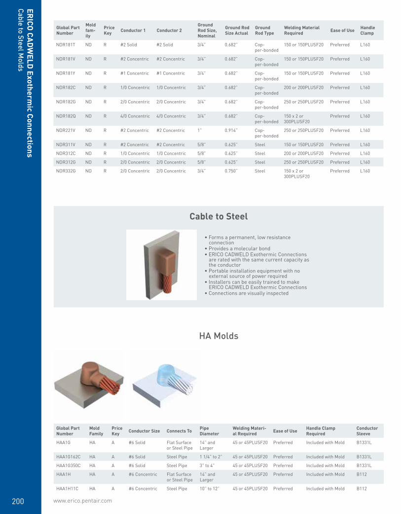
www.erico.pentair.com200
ERICO
CADW
ELD Exotherm
ic Connections
NDR181T ND R #2 Solid #2 Solid 3/4” 0.682” Cop-per-bonded
150 or 150PLUSF20 Preferred L160
NDR181V ND R #2 Concentric #2 Concentric 3/4” 0.682” Cop-per-bonded
150 or 150PLUSF20 Preferred L160
NDR181Y ND R #1 Concentric #1 Concentric 3/4” 0.682” Cop-per-bonded
150 or 150PLUSF20 Preferred L160
NDR182C ND R 1/0 Concentric 1/0 Concentric 3/4” 0.682” Cop-per-bonded
200 or 200PLUSF20 Preferred L160
NDR182G ND R 2/0 Concentric 2/0 Concentric 3/4” 0.682” Cop-per-bonded
250 or 250PLUSF20 Preferred L160
NDR182Q ND R 4/0 Concentric 4/0 Concentric 3/4” 0.682” Cop-per-bonded
150 x 2 or 300PLUSF20
Preferred L160
NDR221V ND R #2 Concentric #2 Concentric 1” 0.914” Cop-per-bonded
250 or 250PLUSF20 Preferred L160
NDR311V ND R #2 Concentric #2 Concentric 5/8” 0.625” Steel 150 or 150PLUSF20 Preferred L160
NDR312C ND R 1/0 Concentric 1/0 Concentric 5/8” 0.625” Steel 200 or 200PLUSF20 Preferred L160
NDR312G ND R 2/0 Concentric 2/0 Concentric 5/8” 0.625” Steel 250 or 250PLUSF20 Preferred L160
NDR332G ND R 2/0 Concentric 2/0 Concentric 3/4” 0.750” Steel 150 x 2 or 300PLUSF20
Preferred L160
HA Molds
Global Part Number
Mold Family
Price Key Conductor Size Connects To Pipe
DiameterWelding Materi-al Required Ease of Use Handle Clamp
RequiredConductor Sleeve
HAA1G HA A #6 Solid Flat Surface or Steel Pipe
14” and Larger
45 or 45PLUSF20 Preferred Included with Mold B1331L
HAA1G162C HA A #6 Solid Steel Pipe 1 1/4” to 2” 45 or 45PLUSF20 Preferred Included with Mold B1331L
HAA1G350C HA A #6 Solid Steel Pipe 3” to 4” 45 or 45PLUSF20 Preferred Included with Mold B1331L
HAA1H HA A #6 Concentric Flat Surface or Steel Pipe
14” and Larger
45 or 45PLUSF20 Preferred Included with Mold B112
HAA1H11C HA A #6 Concentric Steel Pipe 10” to 12” 45 or 45PLUSF20 Preferred Included with Mold B112
Cable to Steel Molds
Cable to Steel
• Forms a permanent, low resistance connection
• Provides a molecular bond• ERICO CADWELD Exothermic Connections
are rated with the same current capacity as the conductor
• Portable installation equipment with no external source of power required
• Installers can be easily trained to make ERICO CADWELD Exothermic Connections
• Connections are visually inspected
Global Part Number
Mold fam-ily
Price Key Conductor 1 Conductor 2
Ground Rod Size, Nominal
Ground Rod Size Actual
Ground Rod Type
Welding Material Required Ease of Use Handle
Clamp
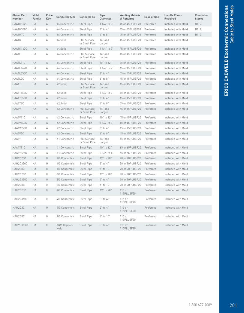
www.erico.pentair.com 1.800.677.9089 201
ERIC
O C
ADW
ELD
Exo
ther
mic
Con
nect
ions
Cabl
e to
Ste
el M
olds
HAA1H162C HA A #6 Concentric Steel Pipe 1 1/4” to 2” 45 or 45PLUSF20 Preferred Included with Mold B112
HAA1H350C HA A #6 Concentric Steel Pipe 3” to 4” 45 or 45PLUSF20 Preferred Included with Mold B112
HAA1H7C HA A #6 Concentric Steel Pipe 6” to 8” 45 or 45PLUSF20 Preferred Included with Mold B112
HAA1K HA A #4 Solid Flat Surface or Steel Pipe
14” and Larger
45 or 45PLUSF20 Preferred Included with Mold
HAA1K162C HA A #4 Solid Steel Pipe 1 1/4” to 2” 45 or 45PLUSF20 Preferred Included with Mold
HAA1L HA A #4 Concentric Flat Surface or Steel Pipe
14” and Larger
45 or 45PLUSF20 Preferred Included with Mold
HAA1L11C HA A #4 Concentric Steel Pipe 10” to 12” 45 or 45PLUSF20 Preferred Included with Mold
HAA1L162C HA A #4 Concentric Steel Pipe 1 1/4” to 2” 45 or 45PLUSF20 Preferred Included with Mold
HAA1L350C HA A #4 Concentric Steel Pipe 3” to 4” 45 or 45PLUSF20 Preferred Included with Mold
HAA1L7C HA A #4 Concentric Steel Pipe 6” to 8” 45 or 45PLUSF20 Preferred Included with Mold
HAA1T HA A #2 Solid Flat Surface or Steel Pipe
14” and Larger
45 or 45PLUSF20 Preferred Included with Mold
HAA1T162C HA A #2 Solid Steel Pipe 1 1/4” to 2” 45 or 45PLUSF20 Preferred Included with Mold
HAA1T350C HA A #2 Solid Steel Pipe 3” to 4” 45 or 45PLUSF20 Preferred Included with Mold
HAA1T7C HA A #2 Solid Steel Pipe 6” to 8” 45 or 45PLUSF20 Preferred Included with Mold
HAA1V HA A #2 Concentric Flat Surface or Steel Pipe
14” and Larger
45 or 45PLUSF20 Preferred Included with Mold
HAA1V11C HA A #2 Concentric Steel Pipe 10” to 12” 45 or 45PLUSF20 Preferred Included with Mold
HAA1V162C HA A #2 Concentric Steel Pipe 1 1/4” to 2” 45 or 45PLUSF20 Preferred Included with Mold
HAA1V350C HA A #2 Concentric Steel Pipe 3” to 4” 45 or 45PLUSF20 Preferred Included with Mold
HAA1V7C HA A #2 Concentric Steel Pipe 6” to 8” 45 or 45PLUSF20 Preferred Included with Mold
HAA1Y HA A #1 Concentric Flat Surface or Steel Pipe
14” and Larger
65 or 65PLUSF20 Preferred Included with Mold
HAA1Y11C HA A #1 Concentric Steel Pipe 10” to 12” 65 or 65PLUSF20 Preferred Included with Mold
HAA1Y325C HA A #1 Concentric Steel Pipe 2 1/2” to 4” 65 or 65PLUSF20 Preferred Included with Mold
HAH2C20C HA H 1/0 Concentric Steel Pipe 12” to 28” 90 or 90PLUSF20 Preferred Included with Mold
HAH2C350C HA H 1/0 Concentric Steel Pipe 3” to 4” 90 or 90PLUSF20 Preferred Included with Mold
HAH2C8C HA H 1/0 Concentric Steel Pipe 6” to 10” 90 or 90PLUSF20 Preferred Included with Mold
HAH2G20C HA H 2/0 Concentric Steel Pipe 12” to 28” 90 or 90PLUSF20 Preferred Included with Mold
HAH2G350C HA H 2/0 Concentric Steel Pipe 3” to 4” 90 or 90PLUSF20 Preferred Included with Mold
HAH2G8C HA H 2/0 Concentric Steel Pipe 6” to 10” 90 or 90PLUSF20 Preferred Included with Mold
HAH2Q20C HA H 4/0 Concentric Steel Pipe 12” to 28” 115 or 115PLUSF20
Preferred Included with Mold
HAH2Q350C HA H 4/0 Concentric Steel Pipe 3” to 4” 115 or 115PLUSF20
Preferred Included with Mold
HAH2Q3C HA H 4/0 Concentric Steel Pipe 2” to 4” 115 or 115PLUSF20
Preferred Included with Mold
HAH2Q8C HA H 4/0 Concentric Steel Pipe 6” to 10” 115 or 115PLUSF20
Preferred Included with Mold
HAH9D350C HA H 7/#6 Copper-weld
Steel Pipe 3” to 4” 115 or 115PLUSF20
Preferred Included with Mold
Global Part Number
Mold Family
Price Key Conductor Size Connects To Pipe
DiameterWelding Materi-al Required Ease of Use Handle Clamp
RequiredConductor Sleeve

www.erico.pentair.com202
ERICO
CADW
ELD Exotherm
ic Connections
HS Molds
Global Part Number
Mold Family
Price Key Conductor Size Connects To Pipe
DiameterWelding Material Required Ease of Use Handle Clamp
RequiredConductor Sleeve
HSC1G HS C #6 Solid Flat Surface or Steel Pipe
14” and Larger 65 or 65PLUSF20 Preferred L160 B1331L
HSC1H HS C #6 Concentric Flat Surface or Steel Pipe
14” and Larger 65 or 65PLUSF20 Preferred L160 B112
HSC1L HS C #4 Concentric Flat Surface or Steel Pipe
14” and Larger 65 or 65PLUSF20 Preferred L160
HSC1T HS C #2 Solid Flat Surface or Steel Pipe
14” and Larger 65 or 65PLUSF20 Preferred L160
HSC1V HS C #2 Concentric Flat Surface or Steel Pipe
14” and Larger 65 or 65PLUSF20 Preferred L160
HSC2C HS C 1/0 Concentric Flat Surface or Steel Pipe
30” and Larger 90 or 90PLUSF20 Preferred L160
HSC2G HS C 2/0 Concentric Flat Surface or Steel Pipe
30” and Larger 90 or 90PLUSF20 Preferred L160
HSC2Q HS C 4/0 Concentric Flat Surface or Steel Pipe
30” and Larger 115 or 115PLUSF20
Preferred L160
HSC2V HS C 250 kcmil Concentric
Flat Surface or Steel Pipe
30” and Larger 115 or 115PLUSF20
Preferred L160
Global Part Number
Mold Family
Price Key Conductor Size Connects To Pipe
Diameter
Welding Material Required
Ease of Use Handle Clamp Required
Conductor Sleeve
HCA1G HC A #6 Solid Flat Surface or Steel Pipe
14” and Larger 45 or 45PLUSF20 Preferred Included with Mold B1331L x 2
HCA1H HC A #6 Concentric Flat Surface or Steel Pipe
14” and Larger 45 or 45PLUSF20 Preferred Included with Mold B112 x 2
HCA1K HC A #4 Solid Flat Surface or Steel Pipe
14” and Larger 45 or 45PLUSF20 Preferred Included with Mold
HCA1L HC A #4 Concentric Flat Surface or Steel Pipe
14” and Larger 45 or 45PLUSF20 Preferred Included with Mold
HCA1T HC A #2 Solid Flat Surface or Steel Pipe
14” and Larger 45 or 45PLUSF20 Preferred Included with Mold
HCA1V HC A #2 Concentric Flat Surface or Steel Pipe
14” and Larger 45 or 45PLUSF20 Preferred Included with Mold
HCA1Y HC A #1 Concentric Flat Surface or Steel Pipe
14” and Larger 65 or 65PLUSF20 Preferred Included with Mold
HC Molds
Cable to Steel Molds

www.erico.pentair.com 1.800.677.9089 203
Global Part Number
Mold Family
Price Key Conductor Size Connects To Pipe
DiameterWelding Material Required Ease of Use Handle Clamp
RequiredConductor Sleeve
HSC1G HS C #6 Solid Flat Surface or Steel Pipe
14” and Larger 65 or 65PLUSF20 Preferred L160 B1331L
HSC1H HS C #6 Concentric Flat Surface or Steel Pipe
14” and Larger 65 or 65PLUSF20 Preferred L160 B112
HSC1L HS C #4 Concentric Flat Surface or Steel Pipe
14” and Larger 65 or 65PLUSF20 Preferred L160
HSC1T HS C #2 Solid Flat Surface or Steel Pipe
14” and Larger 65 or 65PLUSF20 Preferred L160
HSC1V HS C #2 Concentric Flat Surface or Steel Pipe
14” and Larger 65 or 65PLUSF20 Preferred L160
HSC2C HS C 1/0 Concentric Flat Surface or Steel Pipe
30” and Larger 90 or 90PLUSF20 Preferred L160
HSC2G HS C 2/0 Concentric Flat Surface or Steel Pipe
30” and Larger 90 or 90PLUSF20 Preferred L160
HSC2Q HS C 4/0 Concentric Flat Surface or Steel Pipe
30” and Larger 115 or 115PLUSF20
Preferred L160
HSC2V HS C 250 kcmil Concentric
Flat Surface or Steel Pipe
30” and Larger 115 or 115PLUSF20
Preferred L160
Global Part Number
Mold Family
Price Key Conductor Size Connects To Pipe
Diameter
Welding Material Required
Ease of Use Handle Clamp Required
Conductor Sleeve
HCA1G HC A #6 Solid Flat Surface or Steel Pipe
14” and Larger 45 or 45PLUSF20 Preferred Included with Mold B1331L x 2
HCA1H HC A #6 Concentric Flat Surface or Steel Pipe
14” and Larger 45 or 45PLUSF20 Preferred Included with Mold B112 x 2
HCA1K HC A #4 Solid Flat Surface or Steel Pipe
14” and Larger 45 or 45PLUSF20 Preferred Included with Mold
HCA1L HC A #4 Concentric Flat Surface or Steel Pipe
14” and Larger 45 or 45PLUSF20 Preferred Included with Mold
HCA1T HC A #2 Solid Flat Surface or Steel Pipe
14” and Larger 45 or 45PLUSF20 Preferred Included with Mold
HCA1V HC A #2 Concentric Flat Surface or Steel Pipe
14” and Larger 45 or 45PLUSF20 Preferred Included with Mold
HCA1Y HC A #1 Concentric Flat Surface or Steel Pipe
14” and Larger 65 or 65PLUSF20 Preferred Included with Mold
ERIC
O C
ADW
ELD
Exo
ther
mic
Con
nect
ions
Cabl
e to
Ste
el M
olds
HT Molds
VS Molds
Global Part Number
Mold Family
Price Key Conductor Size Connects To Pipe
DiameterWelding Material Required Ease of Use Handle Clamp
Required
HTC1T HT C #2 Solid Flat Surface or Steel Pipe 14” and Larger 65 or 65PLUSF20 Preferred L160
HTC1V HT C #2 Concentric Flat Surface or Steel Pipe 14” and Larger 65 or 65PLUSF20 Preferred L160
HTC2C HT C 1/0 Concentric Flat Surface or Steel Pipe 30” and Larger 90 or 90PLUSF20 Preferred L160
HTC2G HT C 2/0 Concentric Flat Surface or Steel Pipe 30” and Larger 115 or 115PLUSF20 Preferred L160
HTC2Q HT C 4/0 Concentric Flat Surface or Steel Pipe 30” and Larger 150 or 150PLUSF20 Preferred L160
HTC2V HT C 250 kcmil Concentric
Flat Surface or Steel Pipe 30” and Larger 150 or 150PLUSF20 Preferred L160
Global Part Number
Mold Family
Price Key Conductor Size Connects To Pipe
DiameterWelding Materi-al Required Ease of Use Handle Clamp
RequiredConductor Sleeve
VSC1G VS C #6 Solid Flat Surface or Steel Pipe
32” and Larger
45 or 45PLUSF20 Preferred L160 or B396 B1331L
VSC1GV3C VS C #6 Solid Steel Pipe 1-1/2” to 4” 45 or 45PLUSF20 Preferred L160 or B160V B1331L
VSC1GV5C VS C #6 Solid Steel Pipe 4” to 6” 45 or 45PLUSF20 Preferred L160, B160V or B158 B1331L
VSC1GV8C VS C #6 Solid Steel Pipe 6” to 10” 45 or 45PLUSF20 Preferred L160, B160V or B158 B1331L
VSC1H VS C #6 Concentric Flat Surface or Steel Pipe
32” and Larger
45 or 45PLUSF20 Preferred L160 or B396 B112
VSC1HV21C VS C #6 Concentric Steel Pipe 12” to 30” 45 or 45PLUSF20 Preferred L160 B112
VSC1HV3C VS C #6 Concentric Steel Pipe 1-1/2” to 4” 45 or 45PLUSF20 Preferred L160 or B160V B112
VSC1HV8C VS C #6 Concentric Steel Pipe 6” to 10” 45 or 45PLUSF20 Preferred L160, B160V or B158 B112
VSC1K VS C #4 Solid Flat Surface or Steel Pipe
32” and Larger
45 or 45PLUSF20 Preferred L160 or B396
VSC1KV3C VS C #4 Solid Steel Pipe 1-1/2” to 4” 45 or 45PLUSF20 Preferred L160 or B160V
VSC1KV5C VS C #4 Solid Steel Pipe 4” to 6” 45 or 45PLUSF20 Preferred L160, B160V or B158
VSC1KV8C VS C #4 Solid Steel Pipe 6” to 10” 45 or 45PLUSF20 Preferred L160, B160V or B158
VSC1L VS C #4 Concentric Flat Surface or Steel Pipe
32” and Larger
45 or 45PLUSF20 Preferred L160 or B396
VSC1LV21C VS C #4 Concentric Steel Pipe 12” to 30” 45 or 45PLUSF20 Preferred L160
VSC1LV3C VS C #4 Concentric Steel Pipe 1-1/2” to 4” 45 or 45PLUSF20 Preferred L160 or B160V
VSC1LV5C VS C #4 Concentric Steel Pipe 4” to 6” 45 or 45PLUSF20 Preferred L160, B160V or B158
VSC1LV8C VS C #4 Concentric Steel Pipe 6” to 10” 45 or 45PLUSF20 Preferred L160, B160V or B158

www.erico.pentair.com204
VSC1PV3C VS C #3 Solid Steel Pipe 1-1/2” to 4” 45 or 45PLUSF20 Preferred L160 or B160V
VSC1T VS C #2 Solid Flat Surface or Steel Pipe
32” and Larger
45 or 45PLUSF20 Preferred L160 or B396
VSC1TV21C VS C #2 Solid Steel Pipe 12” to 30” 45 or 45PLUSF20 Preferred L160
VSC1TV3C VS C #2 Solid Steel Pipe 1-1/2” to 4” 45 or 45PLUSF20 Preferred L160 or B160V
VSC1TV5C VS C #2 Solid Steel Pipe 4” to 6” 45 or 45PLUSF20 Preferred L160, B160V or B158
VSC1TV8C VS C #2 Solid Steel Pipe 6” to 10” 45 or 45PLUSF20 Preferred L160, B160V or B158
VSC1V VS C #2 Concentric Flat Surface or Steel Pipe
32” and Larger
45 or 45PLUSF20 Preferred L160 or B396
VSC1VV21C VS C #2 Concentric Steel Pipe 12” to 30” 45 or 45PLUSF20 Preferred L160
VSC1VV3C VS C #2 Concentric Steel Pipe 1-1/2” to 4” 45 or 45PLUSF20 Preferred L160 or B160V
VSC1VV5C VS C #2 Concentric Steel Pipe 4” to 6” 45 or 45PLUSF20 Preferred L160, B160V or B158
VSC1VV8C VS C #2 Concentric Steel Pipe 6” to 10” 45 or 45PLUSF20 Preferred L160, B160V or B158
VSC1Y VS C #1 Concentric Flat Surface or Steel Pipe
32” and Larger
65 or 65PLUSF20 Preferred L160 or B396
VSC1YV21C VS C #1 Concentric Steel Pipe 12” to 30” 65 or 65PLUSF20 Preferred L160
VSC1YV3C VS C #1 Concentric Steel Pipe 1-1/2” to 4” 65 or 65PLUSF20 Preferred L160 or B160V
VSC1YV5C VS C #1 Concentric Steel Pipe 4” to 6” 65 or 65PLUSF20 Preferred L160, B160V or B158
VSC1YV8C VS C #1 Concentric Steel Pipe 6” to 10” 65 or 65PLUSF20 Preferred L160, B160V or B158
VSC2C VS C 1/0 Concentric Flat Surface or Steel Pipe
32” and Larger
90 or 90PLUSF20 Preferred L160 or B396
VSC2CV21C VS C 1/0 Concentric Steel Pipe 12” to 30” 90 or 90PLUSF20 Preferred L160
VSC2CV3C VS C 1/0 Concentric Steel Pipe 2” to 4” 90 or 90PLUSF20 Preferred L160 or B160V
VSC2CV5C VS C 1/0 Concentric Steel Pipe 4” to 6” 90 or 90PLUSF20 Preferred L160, B160V or B158
VSC2CV8C VS C 1/0 Concentric Steel Pipe 6” to 10” 90 or 90PLUSF20 Preferred L160, B160V or B158
VSC2G VS C 2/0 Concentric Flat Surface or Steel Pipe
32” and Larger
90 or 90PLUSF20 Preferred L160 or B396
VSC2GV21C VS C 2/0 Concentric Steel Pipe 12” to 30” 90 or 90PLUSF20 Preferred L160
VSC2GV3C VS C 2/0 Concentric Steel Pipe 2” to 4” 90 or 90PLUSF20 Preferred L160 or B160V
VSC2GV5C VS C 2/0 Concentric Steel Pipe 4” to 6” 90 or 90PLUSF20 Preferred L160, B160V or B158
VSC2GV8C VS C 2/0 Concentric Steel Pipe 6” to 10” 90 or 90PLUSF20 Preferred L160, B160V or B158
VSC2Q VS C 4/0 Concentric Flat Surface or Steel Pipe
32” and Larger
115 or 115PLUSF20
Preferred L160 or B396
VSC2QV21C VS C 4/0 Concentric Steel Pipe 12” to 30” 115 or 115PLUSF20
Preferred L160
VSC2QV3C VS C 4/0 Concentric Steel Pipe 2” to 4” 115 or 115PLUSF20
Preferred L160 or B160V
VSC2QV5C VS C 4/0 Concentric Steel Pipe 4” to 6” 115 or 115PLUSF20
Preferred L160, B160V or B158
VSC2QV8C VS C 4/0 Concentric Steel Pipe 6” to 10” 115 or 115PLUSF20
Preferred L160, B160V or B158
VSC2V VS C 250 kcmil Concentric
Flat Surface or Steel Pipe
32” and Larger
115 or 115PLUSF20
Preferred L160 or B396
VSC3A VS C 300 kcmil Concentric
Flat Surface or Steel Pipe
32” and Larger
150 or 150PLUSF20
Preferred L160 or B396
VSC3D VS C 350 kcmil Concentric
Flat Surface or Steel Pipe
32” and Larger
200 or 200PLUSF20
Preferred L160 or B396
VSC3H VS C 400 kcmil Concentric
Flat Surface or Steel Pipe
32” and Larger
200 or 200PLUSF20
Preferred L160 or B396
VSC3Q VS C 500 kcmil Concentric
Flat Surface or Steel Pipe
32” and Larger
200 or 200PLUSF20
Preferred L160 or B396
VSP1K VS P #4 Solid Flat Surface or Steel Pipe
32” and Larger
45 or 45PLUSF20 Preferred Mini EZ Attached or B399BM
VSP1T VS P #2 Solid Flat Surface or Steel Pipe
32” and Larger
45 or 45PLUSF20 Preferred Mini EZ Attached or B399BM
VST1G VS T #6 Solid Flat Surface or Steel Pipe
32” and Larger
25 or 25PLUSF20 Preferred Mini EZ Attached or B399AM
VST1H VS T #6 Concentric Flat Surface or Steel Pipe
32” and Larger
25 or 25PLUSF20 Preferred Mini EZ Attached or B399AM
ERICO
CADW
ELD Exotherm
ic ConnectionsCable to Steel M
olds
Global Part Number
Mold Family
Price Key Conductor Size Connects To Pipe
DiameterWelding Materi-al Required Ease of Use Handle Clamp
RequiredConductor Sleeve
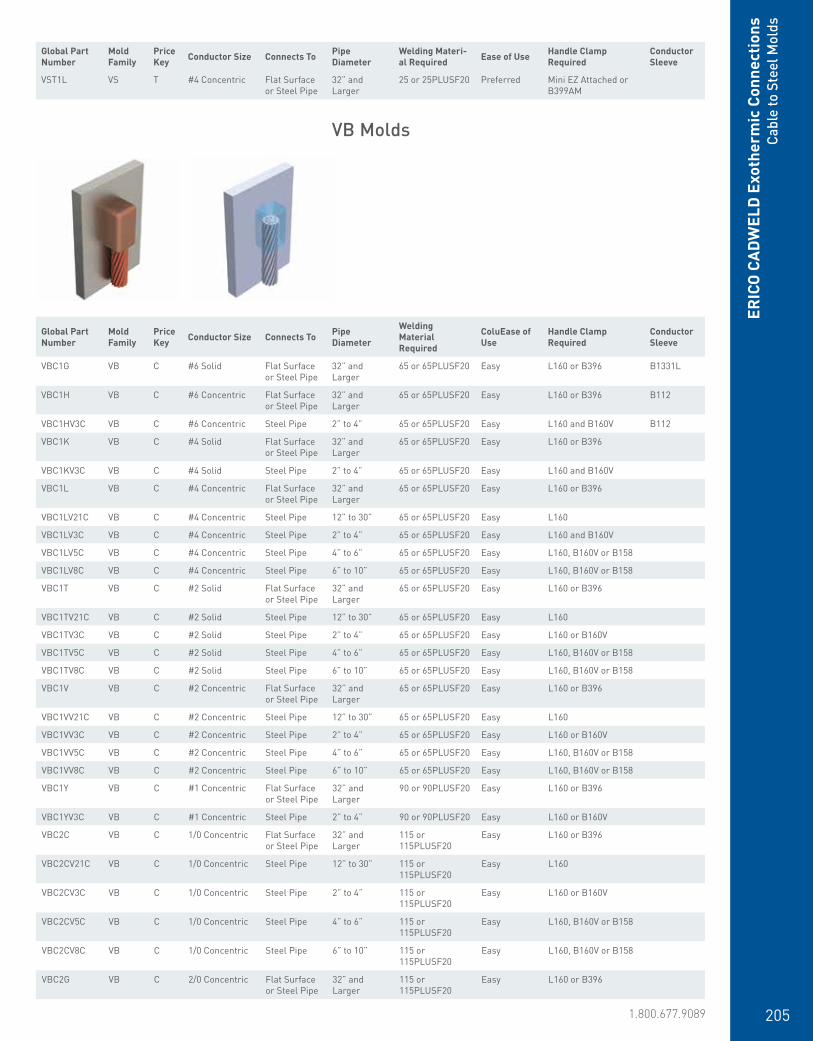
www.erico.pentair.com 1.800.677.9089 205
ERIC
O C
ADW
ELD
Exo
ther
mic
Con
nect
ions
Cabl
e to
Ste
el M
olds
VB Molds
Global Part Number
Mold Family
Price Key Conductor Size Connects To Pipe
Diameter
Welding Material Required
ColuEase of Use
Handle Clamp Required
Conductor Sleeve
VBC1G VB C #6 Solid Flat Surface or Steel Pipe
32” and Larger
65 or 65PLUSF20 Easy L160 or B396 B1331L
VBC1H VB C #6 Concentric Flat Surface or Steel Pipe
32” and Larger
65 or 65PLUSF20 Easy L160 or B396 B112
VBC1HV3C VB C #6 Concentric Steel Pipe 2” to 4” 65 or 65PLUSF20 Easy L160 and B160V B112
VBC1K VB C #4 Solid Flat Surface or Steel Pipe
32” and Larger
65 or 65PLUSF20 Easy L160 or B396
VBC1KV3C VB C #4 Solid Steel Pipe 2” to 4” 65 or 65PLUSF20 Easy L160 and B160V
VBC1L VB C #4 Concentric Flat Surface or Steel Pipe
32” and Larger
65 or 65PLUSF20 Easy L160 or B396
VBC1LV21C VB C #4 Concentric Steel Pipe 12” to 30” 65 or 65PLUSF20 Easy L160
VBC1LV3C VB C #4 Concentric Steel Pipe 2” to 4” 65 or 65PLUSF20 Easy L160 and B160V
VBC1LV5C VB C #4 Concentric Steel Pipe 4” to 6” 65 or 65PLUSF20 Easy L160, B160V or B158
VBC1LV8C VB C #4 Concentric Steel Pipe 6” to 10” 65 or 65PLUSF20 Easy L160, B160V or B158
VBC1T VB C #2 Solid Flat Surface or Steel Pipe
32” and Larger
65 or 65PLUSF20 Easy L160 or B396
VBC1TV21C VB C #2 Solid Steel Pipe 12” to 30” 65 or 65PLUSF20 Easy L160
VBC1TV3C VB C #2 Solid Steel Pipe 2” to 4” 65 or 65PLUSF20 Easy L160 or B160V
VBC1TV5C VB C #2 Solid Steel Pipe 4” to 6” 65 or 65PLUSF20 Easy L160, B160V or B158
VBC1TV8C VB C #2 Solid Steel Pipe 6” to 10” 65 or 65PLUSF20 Easy L160, B160V or B158
VBC1V VB C #2 Concentric Flat Surface or Steel Pipe
32” and Larger
65 or 65PLUSF20 Easy L160 or B396
VBC1VV21C VB C #2 Concentric Steel Pipe 12” to 30” 65 or 65PLUSF20 Easy L160
VBC1VV3C VB C #2 Concentric Steel Pipe 2” to 4” 65 or 65PLUSF20 Easy L160 or B160V
VBC1VV5C VB C #2 Concentric Steel Pipe 4” to 6” 65 or 65PLUSF20 Easy L160, B160V or B158
VBC1VV8C VB C #2 Concentric Steel Pipe 6” to 10” 65 or 65PLUSF20 Easy L160, B160V or B158
VBC1Y VB C #1 Concentric Flat Surface or Steel Pipe
32” and Larger
90 or 90PLUSF20 Easy L160 or B396
VBC1YV3C VB C #1 Concentric Steel Pipe 2” to 4” 90 or 90PLUSF20 Easy L160 or B160V
VBC2C VB C 1/0 Concentric Flat Surface or Steel Pipe
32” and Larger
115 or 115PLUSF20
Easy L160 or B396
VBC2CV21C VB C 1/0 Concentric Steel Pipe 12” to 30” 115 or 115PLUSF20
Easy L160
VBC2CV3C VB C 1/0 Concentric Steel Pipe 2” to 4” 115 or 115PLUSF20
Easy L160 or B160V
VBC2CV5C VB C 1/0 Concentric Steel Pipe 4” to 6” 115 or 115PLUSF20
Easy L160, B160V or B158
VBC2CV8C VB C 1/0 Concentric Steel Pipe 6” to 10” 115 or 115PLUSF20
Easy L160, B160V or B158
VBC2G VB C 2/0 Concentric Flat Surface or Steel Pipe
32” and Larger
115 or 115PLUSF20
Easy L160 or B396
Global Part Number
Mold Family
Price Key Conductor Size Connects To Pipe
DiameterWelding Materi-al Required Ease of Use Handle Clamp
RequiredConductor Sleeve
VST1L VS T #4 Concentric Flat Surface or Steel Pipe
32” and Larger
25 or 25PLUSF20 Preferred Mini EZ Attached or B399AM

www.erico.pentair.com206
VBC2GV21C VB C 2/0 Concentric Steel Pipe 12” to 30” 115 or 115PLUSF20
Easy L160
VBC2GV3C VB C 2/0 Concentric Steel Pipe 2” to 4” 115 or 115PLUSF20
Easy L160 or B160V
VBC2GV5C VB C 2/0 Concentric Steel Pipe 4” to 6” 115 or 115PLUSF20
Easy L160, B160V or B158
VBC2GV8C VB C 2/0 Concentric Steel Pipe 6” to 10” 115 or 115PLUSF20
Easy L160, B160V or B158
VBC2Q VB C 4/0 Concentric Flat Surface or Steel Pipe
32” and Larger
150 or 150PLUSF20
Easy L160 or B396
VBC2QV21C VB C 4/0 Concentric Steel Pipe 12” to 30” 150 or 150PLUSF20
Easy L160
VBC2QV3C VB C 4/0 Concentric Steel Pipe 1-1/2” to 4” 150 or 150PLUSF20
Easy L160 or B160V
VBC2QV5C VB C 4/0 Concentric Steel Pipe 4” to 6” 150 or 150PLUSF20
Easy L160, B160V or B158
VBC2QV8C VB C 4/0 Concentric Steel Pipe 6” to 10” 150 or 150PLUSF20
Easy L160, B160V or B158
VBC2V VB C 250 kcmil Concentric
Flat Surface or Steel Pipe
32” and Larger
200 or 200PLUSF20
Easy L160 or B396
VBC2VV5C VB C 250 kcmil Concentric
Steel Pipe 4” to 6” 200 or 200PLUSF20
Easy L160, B160V or B158
VBC3A VB C 300 kcmil Concentric
Flat Surface or Steel Pipe
32” and Larger
200 or 200PLUSF20
Easy L160 or B396
VBC3H VB C 400 kcmil Concentric
Flat Surface or Steel Pipe
32” and Larger
250 or 250PLUSF20
Easy L160 or B396
VBR3Q VB R 500 kcmil Concentric
Flat Surface or Steel Pipe
32” and Larger
150 x 2 or 300PLUSF20
Easy L160 or B396
Global Part Number
Mold Family
Price Key Conductor Size Connects To Pipe
Diameter
Welding Material Required
Ease of Use Handle Clamp Required
Conductor Sleeve
VFC1G VF C #6 Solid Flat Surface or Steel Pipe
32” and Larger
65 or 65PLUSF20 Preferred L160 or B396 B1331L
VFC1GV3C VF C #6 Solid Steel Pipe 2” to 4” 65 or 65PLUSF20 Preferred L160 or B160V B1331L
VFC1H VF C #6 Concentric Flat Surface or Steel Pipe
32” and Larger
65 or 65PLUSF20 Preferred L160 or B396 B112
VFC1HV3C VF C #6 Concentric Steel Pipe 2” to 4” 65 or 65PLUSF20 Preferred L160 or B160V B112
VFC1K VF C #4 Solid Flat Surface or Steel Pipe
32” and Larger
65 or 65PLUSF20 Preferred L160 or B396
VFC1KV3C VF C #4 Solid Steel Pipe 2” to 4” 65 or 65PLUSF20 Preferred L160 or B160V
VFC1L VF C #4 Concentric Flat Surface or Steel Pipe
32” and Larger
65 or 65PLUSF20 Preferred L160 or B396
VFC1LV21C VF C #4 Concentric Steel Pipe 12” to 30” 65 or 65PLUSF20 Preferred L160
VFC1LV3C VF C #4 Concentric Steel Pipe 2” to 4” 65 or 65PLUSF20 Preferred L160 or B160V
VFC1LV8C VF C #4 Concentric Steel Pipe 6” to 10” 65 or 65PLUSF20 Preferred L160, B160V or B158
VFC1T VF C #2 Solid Flat Surface or Steel Pipe
32” and Larger
65 or 65PLUSF20 Preferred L160 or B396
VF Molds
ERICO
CADW
ELD Exotherm
ic ConnectionsCable to Steel M
olds
Global Part Number
Mold Family
Price Key Conductor Size Connects To Pipe
Diameter
Welding Material Required
ColuEase of Use
Handle Clamp Required
Conductor Sleeve

www.erico.pentair.com 1.800.677.9089 207
ERIC
O C
ADW
ELD
Exo
ther
mic
Con
nect
ions
Cabl
e to
Ste
el M
olds
VFC1TV21C VF C #2 Solid Steel Pipe 12” to 30” 65 or 65PLUSF20 Preferred L160
VFC1TV3C VF C #2 Solid Steel Pipe 2” to 4” 65 or 65PLUSF20 Preferred L160 or B160V
VFC1TV5C VF C #2 Solid Steel Pipe 4” to 6” 65 or 65PLUSF20 Preferred L160, B160V or B158
VFC1V VF C #2 Concentric Flat Surface or Steel Pipe
32” and Larger
65 or 65PLUSF20 Preferred L160 or B396
VFC1VV3C VF C #2 Concentric Steel Pipe 2” to 4” 65 or 65PLUSF20 Preferred L160 or B160V
VFC1VV5C VF C #2 Concentric Steel Pipe 4” to 6” 65 or 65PLUSF20 Preferred L160, B160V or B158
VFC1VV8C VF C #2 Concentric Steel Pipe 6” to 10” 65 or 65PLUSF20 Preferred L160, B160V or B158
VFC1Y VF C #1 Concentric Flat Surface or Steel Pipe
32” and Larger
90 or 90PLUSF20 Preferred L160 or B396
VFC2C VF C 1/0 Concentric Flat Surface or Steel Pipe
32” and Larger
150 or 150PLUSF20
Preferred L160 or B396
VFC2CV3C VF C 1/0 Concentric Steel Pipe 2” to 4” 150 or 150PLUSF20
Preferred L160 or B160V
VFC2CV8C VF C 1/0 Concentric Steel Pipe 6” to 10” 150 or 150PLUSF20
Preferred L160, B160V or B158
VFC2G VF C 2/0 Concentric Flat Surface or Steel Pipe
32” and Larger
150 or 150PLUSF20
Preferred L160 or B396
VFC2GV3C VF C 2/0 Concentric Steel Pipe 2” to 4” 150 or 150PLUSF20
Preferred L160 or B160V
VFC2GV5C VF C 2/0 Concentric Steel Pipe 4” to 6” 150 or 150PLUSF20
Preferred L160, B160V or B158
VFC2GV8C VF C 2/0 Concentric Steel Pipe 6” to 10” 150 or 150PLUSF20
Preferred L160, B160V or B158
VFF3Q VF F 500 kcmil Concentric
Flat Surface or Steel Pipe
32” and Larger
200 x 2 or 400PLUSF20
Preferred L159 and B159M
VFR2Q VF R 4/0 Concentric Flat Surface or Steel Pipe
32” and Larger
200 or 200PLUSF20
Preferred L160 or B396
VFR2QV21C VF R 4/0 Concentric Steel Pipe 12” to 30” 200 or 200PLUSF20
Preferred L160
VFR2QV3C VF R 4/0 Concentric Steel Pipe 2” to 4” 200 or 200PLUSF20
Preferred L160 or B160V
VFR2QV5C VF R 4/0 Concentric Steel Pipe 4” to 6” 200 or 200PLUSF20
Preferred L160, B160V or B158
VFR2QV8C VF R 4/0 Concentric Steel Pipe 6” to 10” 200 or 200PLUSF20
Preferred L160, B160V or B158
VFR2V VF R 250 kcmil Concentric
Flat Surface or Steel Pipe
32” and Larger
200 or 200PLUSF20
Preferred L160 or B396
VFR3A VF R 300 kcmil Concentric
Flat Surface or Steel Pipe
32” and Larger
250 or 250PLUSF20
Preferred L160 or B396
VFR3D VF R 350 kcmil Concentric
Flat Surface or Steel Pipe
32” and Larger
150 x 2 or 300PLUSF20
Preferred L160 or B396
VFR3H VF R 400 kcmil Concentric
Flat Surface or Steel Pipe
32” and Larger
150 x 2 or 300PLUSF20
Preferred L160 or B396
Global Part Number
Mold Family
Price Key Conductor Size Connects To Pipe
Diameter
Welding Material Required
Ease of Use Handle Clamp Required
Conductor Sleeve
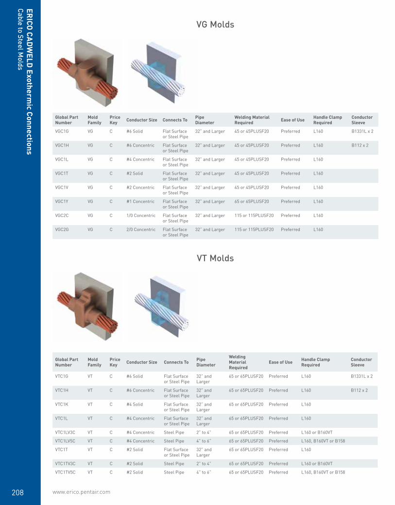
www.erico.pentair.com208
Global Part Number
Mold Family
Price Key Conductor Size Connects To Pipe
DiameterWelding Material Required Ease of Use Handle Clamp
RequiredConductor Sleeve
VGC1G VG C #6 Solid Flat Surface or Steel Pipe
32” and Larger 45 or 45PLUSF20 Preferred L160 B1331L x 2
VGC1H VG C #6 Concentric Flat Surface or Steel Pipe
32” and Larger 45 or 45PLUSF20 Preferred L160 B112 x 2
VGC1L VG C #4 Concentric Flat Surface or Steel Pipe
32” and Larger 45 or 45PLUSF20 Preferred L160
VGC1T VG C #2 Solid Flat Surface or Steel Pipe
32” and Larger 45 or 45PLUSF20 Preferred L160
VGC1V VG C #2 Concentric Flat Surface or Steel Pipe
32” and Larger 45 or 45PLUSF20 Preferred L160
VGC1Y VG C #1 Concentric Flat Surface or Steel Pipe
32” and Larger 65 or 65PLUSF20 Preferred L160
VGC2C VG C 1/0 Concentric Flat Surface or Steel Pipe
32” and Larger 115 or 115PLUSF20 Preferred L160
VGC2G VG C 2/0 Concentric Flat Surface or Steel Pipe
32” and Larger 115 or 115PLUSF20 Preferred L160
VG Molds
VT Molds
Global Part Number
Mold Family
Price Key Conductor Size Connects To Pipe
Diameter
Welding Material Required
Ease of Use Handle Clamp Required
Conductor Sleeve
VTC1G VT C #6 Solid Flat Surface or Steel Pipe
32” and Larger
65 or 65PLUSF20 Preferred L160 B1331L x 2
VTC1H VT C #6 Concentric Flat Surface or Steel Pipe
32” and Larger
65 or 65PLUSF20 Preferred L160 B112 x 2
VTC1K VT C #4 Solid Flat Surface or Steel Pipe
32” and Larger
65 or 65PLUSF20 Preferred L160
VTC1L VT C #4 Concentric Flat Surface or Steel Pipe
32” and Larger
65 or 65PLUSF20 Preferred L160
VTC1LV3C VT C #4 Concentric Steel Pipe 2” to 4” 65 or 65PLUSF20 Preferred L160 or B160VT
VTC1LV5C VT C #4 Concentric Steel Pipe 4” to 6” 65 or 65PLUSF20 Preferred L160, B160VT or B158
VTC1T VT C #2 Solid Flat Surface or Steel Pipe
32” and Larger
65 or 65PLUSF20 Preferred L160
VTC1TV3C VT C #2 Solid Steel Pipe 2” to 4” 65 or 65PLUSF20 Preferred L160 or B160VT
VTC1TV5C VT C #2 Solid Steel Pipe 4” to 6” 65 or 65PLUSF20 Preferred L160, B160VT or B158
ERICO
CADW
ELD Exotherm
ic ConnectionsCable to Steel M
olds

www.erico.pentair.com 1.800.677.9089 209
ERIC
O C
ADW
ELD
Exo
ther
mic
Con
nect
ions
Cabl
e to
Ste
el M
olds
VV Molds
VTC1TV8C VT C #2 Solid Steel Pipe 6” to 10” 65 or 65PLUSF20 Preferred L160, B160VT or B158
VTC1V VT C #2 Concentric Flat Surface or Steel Pipe
32” and Larger
65 or 65PLUSF20 Preferred L160
VTC1VV3C VT C #2 Concentric Steel Pipe 2” to 4” 65 or 65PLUSF20 Preferred L160 or B160VT
VTC2C VT C 1/0 Concentric Flat Surface or Steel Pipe
32” and Larger
115 or 115PLUSF20
Preferred L160
VTC2CV3C VT C 1/0 Concentric Steel Pipe 2” to 4” 115 or 115PLUSF20
Preferred L160 or B160VT
VTC2G VT C 2/0 Concentric Flat Surface or Steel Pipe
32” and Larger
115 or 115PLUSF20
Preferred L160
VTC2GV3C VT C 2/0 Concentric Steel Pipe 2” to 4” 115 or 115PLUSF20
Preferred L160 or B160VT
VTC2Q VT C 4/0 Concentric Flat Surface or Steel Pipe
32” and Larger
150 or 150PLUSF20
Preferred L160
VTC2QV21C VT C 4/0 Concentric Steel Pipe 12” to 30” 150 or 150PLUSF20
Preferred L160
VTC2QV3C VT C 4/0 Concentric Steel Pipe 2” to 4” 150 or 150PLUSF20
Preferred L160 or B160VT
VTC2QV5C VT C 4/0 Concentric Steel Pipe 4” to 6” 150 or 150PLUSF20
Preferred L160, B160VT or B158
VTC2V VT C 250 kcmil Concentric
Flat Surface or Steel Pipe
32” and Larger
150 or 150PLUSF20
Preferred L160
VTD3Q VT D 500 kcmil Concentric
Flat Surface or Steel Pipe
32” and Larger
500 or 500PLUSF20
Preferred L159
Global Part Number
Mold Family
Price Key Conductor Size Connects To Pipe
Diameter
Welding Material Required
Ease of Use Handle Clamp Required
Conductor Sleeve
VVC1G VV C #6 Solid Flat Surface or Steel Pipe
32” and Larger
90 or 90PLUSF20 Preferred L160 or B396 B1331L x 2
VVC1GV3C VV C #6 Solid Steel Pipe 1-1/2” to 4” 90 or 90PLUSF20 Preferred L160 or B160V B1331L x 2
VVC1H VV C #6 Concentric Flat Surface or Steel Pipe
32” and Larger
90 or 90PLUSF20 Preferred L160 or B396 B112 x 2
VVC1K VV C #4 Solid Flat Surface or Steel Pipe
32” and Larger
90 or 90PLUSF20 Preferred L160 or B396
VVC1L VV C #4 Concentric Flat Surface or Steel Pipe
32” and Larger
90 or 90PLUSF20 Preferred L160 or B396
VVC1LV3C VV C #4 Concentric Steel Pipe 1-1/2” to 4” 90 or 90PLUSF20 Preferred L160 or B160V
VVC1T VV C #2 Solid Flat Surface or Steel Pipe
32” and Larger
115 or 115PLUSF20
Preferred L160 or B396
VVC1TV3C VV C #2 Solid Steel Pipe 1-1/2” to 4” 115 or 115PLUSF20
Preferred L160 or B160V
VVC1V VV C #2 Concentric Flat Surface or Steel Pipe
32” and Larger
115 or 115PLUSF20
Preferred L160 or B396
VVC1VV21C VV C #2 Concentric Steel Pipe 12” to 30” 115 or 115PLUSF20
Preferred L160
VVC1VV3C VV C #2 Concentric Steel Pipe 1-1/2” to 4” 115 or 115PLUSF20
Preferred L160 or B160V
Global Part Number
Mold Family
Price Key Conductor Size Connects To Pipe
Diameter
Welding Material Required
Ease of Use Handle Clamp Required
Conductor Sleeve

www.erico.pentair.com210
VVC1Y VV C #1 Concentric Flat Surface or Steel Pipe
32” and Larger
115 or 115PLUSF20
Preferred L160 or B396
VVR2C VV R 1/0 Concentric Flat Surface or Steel Pipe
32” and Larger
200 or 200PLUSF20
Preferred L160 or B396
VVR2CV3C VV R 1/0 Concentric Steel Pipe 2” to 4” 200 or 200PLUSF20
Preferred L160 or B160V
VVR2G VV R 2/0 Concentric Flat Surface or Steel Pipe
32” and Larger
200 or 200PLUSF20
Preferred L160 or B396
VVR2GV21C VV R 2/0 Concentric Steel Pipe 12” to 30” 200 or 200PLUSF20
Preferred L160
VVR2GV3C VV R 2/0 Concentric Steel Pipe 2” to 4” 200 or 200PLUSF20
Preferred L160 or B160V
VVR2GV5C VV R 2/0 Concentric Steel Pipe 4” to 6” 200 or 200PLUSF20
Preferred L160, B160V or B158
VVR2Q VV R 4/0 Concentric Flat Surface or Steel Pipe
32” and Larger
250 or 250PLUSF20
Preferred L160 or B396
VVR2QV21C VV R 4/0 Concentric Steel Pipe 12” to 30” 250 or 250PLUSF20
Preferred L160
VVR2QV3C VV R 4/0 Concentric Steel Pipe 2” to 4” 250 or 250PLUSF20
Preferred L160 or B160V
VVR2QV8C VV R 4/0 Concentric Steel Pipe 6” to 10” 250 or 250PLUSF20
Preferred L160, B160V or B158
VVR2V VV R 250 kcmil Concentric
Flat Surface or Steel Pipe
32” and Larger
250 or 250PLUSF20
Preferred L160 or B396
Global Part Number
Mold Family
Price Key Conductor Size Connects To Welding Material Required Ease of Use Handle Clamp
RequiredConductor Sleeve
VNC1GLH VN C #6 Solid Flat Surface 45 or 45PLUSF20 Preferred L160 B1331L
VNC1HLH VN C #6 Concentric Flat Surface 45 or 45PLUSF20 Preferred L160 B112
VNC1HRH VN C #6 Concentric Flat Surface 45 or 45PLUSF20 Preferred L160 B112
VNC1LLH VN C #4 Concentric Flat Surface 45 or 45PLUSF20 Preferred L160
VNC1LRH VN C #4 Concentric Flat Surface 45 or 45PLUSF20 Preferred L160
VNC1TLH VN C #2 Solid Flat Surface 45 or 45PLUSF20 Preferred L160
VNC1TRH VN C #2 Solid Flat Surface 45 or 45PLUSF20 Preferred L160
VNC1VLH VN C #2 Concentric Flat Surface 45 or 45PLUSF20 Preferred L160
VNC1VRH VN C #2 Concentric Flat Surface 45 or 45PLUSF20 Preferred L160
VNC2CLH VN C 1/0 Concentric Flat Surface 90 or 90PLUSF20 Preferred L160
VNC2CRH VN C 1/0 Concentric Flat Surface 90 or 90PLUSF20 Preferred L160
VNC2GLH VN C 2/0 Concentric Flat Surface 90 or 90PLUSF20 Preferred L160
VNC2GRH VN C 2/0 Concentric Flat Surface 90 or 90PLUSF20 Preferred L160
VNC2LLH VN C 3/0 Concentric Flat Surface 115 or 115PLUSF20 Preferred L160
VNC2LRH VN C 3/0 Concentric Flat Surface 115 or 115PLUSF20 Preferred L160
VNC2QLH VN C 4/0 Concentric Flat Surface 115 or 115PLUSF20 Preferred L160
VNC2QRH VN C 4/0 Concentric Flat Surface 115 or 115PLUSF20 Preferred L160
VNC2VLH VN C 250 kcmil Concentric Flat Surface 115 or 115PLUSF20 Preferred L160
VNC2VRH VN C 250 kcmil Concentric Flat Surface 115 or 115PLUSF20 Preferred L160
VN Molds
ERICO
CADW
ELD Exotherm
ic ConnectionsCable to Steel M
olds
Global Part Number
Mold Family
Price Key Conductor Size Connects To Pipe
Diameter
Welding Material Required
Ease of Use Handle Clamp Required
Conductor Sleeve

www.erico.pentair.com 1.800.677.9089 211
ERIC
O C
ADW
ELD
Exo
ther
mic
Con
nect
ions
Cabl
e to
Lug
or
Busb
ar M
olds
Cable to Lug or Busbar
• Forms a permanent, low resistance connection
• Provides a molecular bond• ERICO CADWELD Exothermic Connections
are rated with the same current capacity as the conductor
• Portable installation equipment with no external source of power required
• Installers can be easily trained to make ERICO CADWELD Exothermic Connections
• Connections are visually inspected
GL Molds
Global Part Number
Mold Family
Price Key Conductor Size Lug / Busbar Size Welding Material
Required Ease of Use Handle Clamp required
Conductor Sleeve
GLCCE1G GL C #6 Solid 1/8” x 1” 32 or 32PLUSF20 Preferred L160 B1331L
GLCCE1H GL C #6 Concentric 1/8” x 1” 32 or 32PLUSF20 Preferred L160 B112
GLCCE1K GL C #4 Solid 1/8” x 1” 32 or 32PLUSF20 Preferred L160
GLCCE1L GL C #4 Concentric 1/8” x 1” 32 or 32PLUSF20 Preferred L160
GLCCE1T GL C #2 Solid 1/8” x 1” 32 or 32PLUSF20 Preferred L160
GLCCE1V GL C #2 Concentric 1/8” x 1” 32 or 32PLUSF20 Preferred L160
GLCCE1Y GL C #1 Concentric 1/8” x 1” 32 or 32PLUSF20 Preferred L160
GLCCE2C GL C 1/0 Concentric 1/8” x 1” 45 or 45PLUSF20 Preferred L160
GLCCE2G GL C 2/0 Concentric 1/8” x 1” 45 or 45PLUSF20 Preferred L160
GLCCE2Q GL C 4/0 Concentric 1/8” x 1” 65 or 65PLUSF20 Preferred L160
GLCDE1H GL C #6 Concentric 3/16” x 1” 45 or 45PLUSF20 Preferred L160 B112
GLCDE2C GL C 1/0 Concentric 3/16” x 1” 45 or 45PLUSF20 Preferred L160
GLCDE2G GL C 2/0 Concentric 3/16” x 1” 65 or 65PLUSF20 Preferred L160
GLCDE2Q GL C 4/0 Concentric 3/16” x 1” 65 or 65PLUSF20 Preferred L160
GLCDE2V GL C 250 kcmil Concentric 3/16” x 1” 65 or 65PLUSF20 Preferred L160
GLCEE2Q GL C 4/0 Concentric 1/4” x 1” 65 or 65PLUSF20 Preferred L160
GLCEE2V GL C 250 kcmil Concentric 1/4” x 1” 90 or 90PLUSF20 Preferred L160
GLCEE3A GL C 300 kcmil Concentric 1/4” x 1” 90 or 90PLUSF20 Preferred L160
GLCEE3D GL C 350 kcmil Concentric 1/4” x 1” 90 or 90PLUSF20 Preferred L160
GLCEG1V GL C #2 Concentric 1/4” x 1 1/2” 90 or 90PLUSF20 Preferred L160
GLCEG2C GL C 1/0 Concentric 1/4” x 1 1/2” 115 or 115PLUSF20 Preferred L160
GLCEG2G GL C 2/0 Concentric 1/4” x 1 1/2” 115 or 115PLUSF20 Preferred L160
GLCEG2Q GL C 4/0 Concentric 1/4” x 1 1/2” 115 or 115PLUSF20 Preferred L160
GLCEG2V GL C 250 kcmil Concentric 1/4” x 1 1/2” 115 or 115PLUSF20 Preferred L160
GLCEG3H GL C 400 kcmil Concentric 1/4” x 1 1/2” 150 or 150PLUSF20 Preferred L160
GLCEG3Q GL C 500 kcmil Concentric 1/4” x 1 1/2” 150 or 150PLUSF20 Preferred L160
GLPCC1T GL P #2 Solid 1/8” x 5/8” 25 or 25PLUSF20 Preferred B399B Mini EZ Attached

www.erico.pentair.com212
ERICO
CADW
ELD Exotherm
ic ConnectionsCable to Lug or Busbar M
olds
LA Molds
Global Part Number
Mold Family
Price Key Conductor Size Lug / Busbar Size Welding Material
Required Ease of Use Handle Clamp required
Conductor Sleeve
LAC1GCE LA C #6 Solid 1/8” x 1” 45 or 45PLUSF20 Preferred L160 B1331L
LAC1GEE LA C #6 Solid 1/4” x 1” 65 or 65PLUSF20 Preferred L160 B1331L
LAC1HCE LA C #6 Concentric 1/8” x 1” 45 or 45PLUSF20 Preferred L160 B112
LAC1HEE LA C #6 Concentric 1/4” x 1” 65 or 65PLUSF20 Preferred L160 B112
LAC1HEG LA C #6 Concentric 1/4” x 1 1/2” 65 or 65PLUSF20 Preferred L160 B112
LAC1KCE LA C #4 Solid 1/8” x 1” 45 or 45PLUSF20 Preferred L160
LAC1KEE LA C #4 Solid 1/4” x 1” 45 or 45PLUSF20 Preferred L160
LAC1LCE LA C #4 Concentric 1/8” x 1” 45 or 45PLUSF20 Preferred L160
LAC1LEE LA C #4 Concentric 1/4” x 1” 45 or 45PLUSF20 Preferred L160
LAC1LEG LA C #4 Concentric 1/4” x 1 1/2” 45 or 45PLUSF20 Preferred L160
LAC1TCE LA C #2 Solid 1/8” x 1” 45 or 45PLUSF20 Preferred L160
LAC1TDE LA C #2 Solid 3/16” x 1” 45 or 45PLUSF20 Preferred L160
LAC1TEE LA C #2 Solid 1/4” x 1” 65 or 65PLUSF20 Preferred L160
LAC1TEG LA C #2 Solid 1/4” x 1 1/2” 65 or 65PLUSF20 Preferred L160
LAC1TEK LA C #2 Solid 1/4” x 3” and wider 65 or 65PLUSF20 Preferred L160
LAC1VCE LA C #2 Concentric 1/8” x 1” 45 or 45PLUSF20 Preferred L160
LAC1VDE LA C #2 Concentric 3/16” x 1” 45 or 45PLUSF20 Preferred L160
LAC1VEE LA C #2 Concentric 1/4” x 1” 65 or 65PLUSF20 Preferred L160
LAC1VEG LA C #2 Concentric 1/4” x 1 1/2” 65 or 65PLUSF20 Preferred L160
LAC1YCE LA C #1 Concentric 1/8” x 1” 45 or 45PLUSF20 Preferred L160
LAC2C002 LA C 1/0 Concentric 1/4” x 1” 65 or 65PLUSF20 Preferred L160
LAC2CCE LA C 1/0 Concentric 1/8” x 1” 45 or 45PLUSF20 Preferred L160
LAC2CDE LA C 1/0 Concentric 3/16” x 1” 65 or 65PLUSF20 Preferred L160
LAC2CEE LA C 1/0 Concentric 1/4” x 1” 65 or 65PLUSF20 Preferred L160
LAC2CEG LA C 1/0 Concentric 1/4” x 1 1/2” 65 or 65PLUSF20 Preferred L160
LAC2CEK LA C 1/0 Concentric 1/4” x 3” and wider 65 or 65PLUSF20 Preferred L160
LAC2G002 LA C 2/0 Concentric 1/4” x 1” 65 or 65PLUSF20 Preferred L160
LAC2GCE LA C 2/0 Concentric 1/8” x 1” 65 or 65PLUSF20 Preferred L160
LAC2GCEW LA C 2/0 Concentric 1/8” x 1” 65 or 65PLUSF20 Preferred L160
LAC2GDE LA C 2/0 Concentric 3/16” x 1” 65 or 65PLUSF20 Preferred L160
LAC2GEE LA C 2/0 Concentric 1/4” x 1” 65 or 65PLUSF20 Preferred L160
LAC2GEEW LA C 2/0 Concentric 1/4” x 1” 65 or 65PLUSF20 Preferred L160
LAC2GEG LA C 2/0 Concentric 1/4” x 1 1/2” 65 or 65PLUSF20 Preferred L160
LAC2Q002 LA C 4/0 Concentric 1/4” x 1” 90 or 90PLUSF20 Preferred L160
LAC2QCE LA C 4/0 Concentric 1/8” x 1” 65 or 65PLUSF20 Preferred L160
LAC2QCEW LA C 4/0 Concentric 1/8” x 1” 65 or 65PLUSF20 Preferred L160
LAC2QDE LA C 4/0 Concentric 3/16” x 1” 90 or 90PLUSF20 Preferred L160
LAC2QEE LA C 4/0 Concentric 1/4” x 1” 90 or 90PLUSF20 Preferred L160
LAC2QEEW LA C 4/0 Concentric 1/4” x 1” 90 or 90PLUSF20 Preferred L160
LAC2QEG LA C 4/0 Concentric 1/4” x 1 1/2” 90 or 90PLUSF20 Preferred L160
LAC2QEGW LA C 4/0 Concentric 1/4” x 1 1/2” 90 or 90PLUSF20 Preferred L160
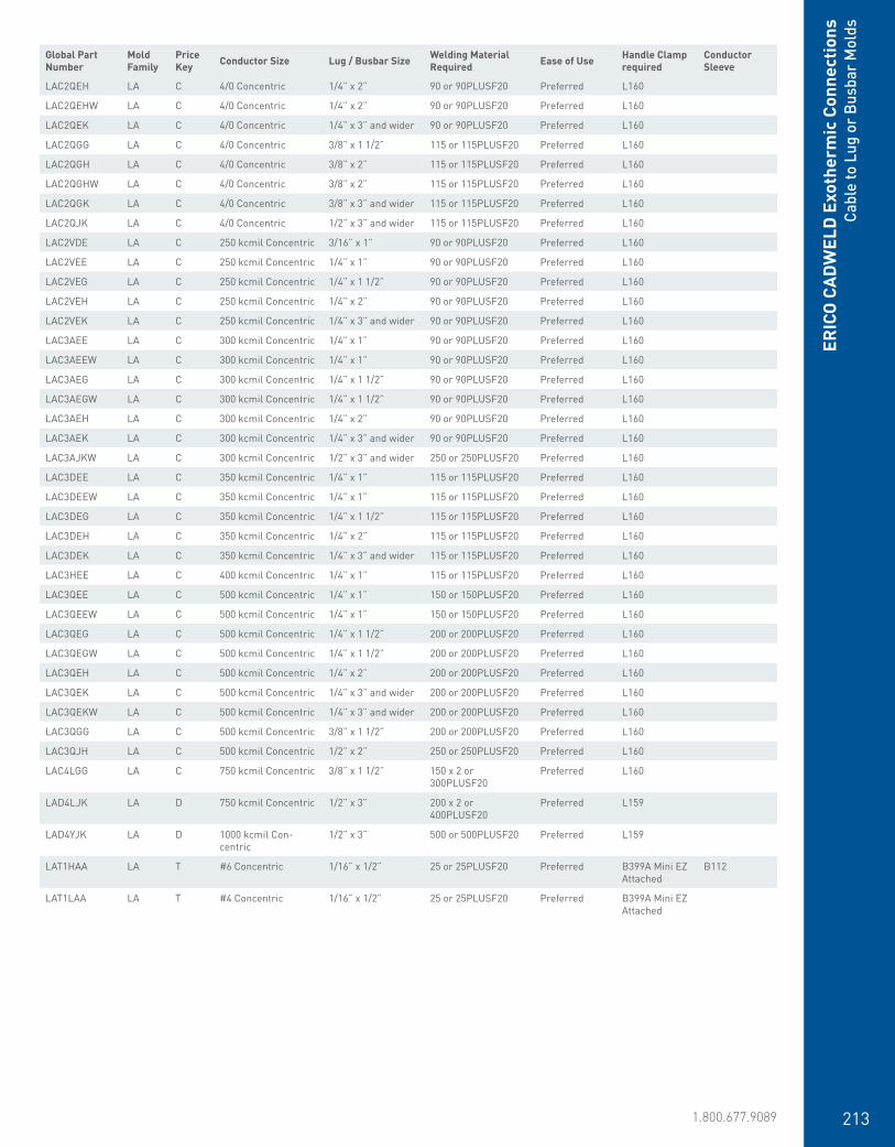
www.erico.pentair.com 1.800.677.9089 213
ERIC
O C
ADW
ELD
Exo
ther
mic
Con
nect
ions
Cabl
e to
Lug
or
Busb
ar M
olds
LAC2QEH LA C 4/0 Concentric 1/4” x 2” 90 or 90PLUSF20 Preferred L160
LAC2QEHW LA C 4/0 Concentric 1/4” x 2” 90 or 90PLUSF20 Preferred L160
LAC2QEK LA C 4/0 Concentric 1/4” x 3” and wider 90 or 90PLUSF20 Preferred L160
LAC2QGG LA C 4/0 Concentric 3/8” x 1 1/2” 115 or 115PLUSF20 Preferred L160
LAC2QGH LA C 4/0 Concentric 3/8” x 2” 115 or 115PLUSF20 Preferred L160
LAC2QGHW LA C 4/0 Concentric 3/8” x 2” 115 or 115PLUSF20 Preferred L160
LAC2QGK LA C 4/0 Concentric 3/8” x 3” and wider 115 or 115PLUSF20 Preferred L160
LAC2QJK LA C 4/0 Concentric 1/2” x 3” and wider 115 or 115PLUSF20 Preferred L160
LAC2VDE LA C 250 kcmil Concentric 3/16” x 1” 90 or 90PLUSF20 Preferred L160
LAC2VEE LA C 250 kcmil Concentric 1/4” x 1” 90 or 90PLUSF20 Preferred L160
LAC2VEG LA C 250 kcmil Concentric 1/4” x 1 1/2” 90 or 90PLUSF20 Preferred L160
LAC2VEH LA C 250 kcmil Concentric 1/4” x 2” 90 or 90PLUSF20 Preferred L160
LAC2VEK LA C 250 kcmil Concentric 1/4” x 3” and wider 90 or 90PLUSF20 Preferred L160
LAC3AEE LA C 300 kcmil Concentric 1/4” x 1” 90 or 90PLUSF20 Preferred L160
LAC3AEEW LA C 300 kcmil Concentric 1/4” x 1” 90 or 90PLUSF20 Preferred L160
LAC3AEG LA C 300 kcmil Concentric 1/4” x 1 1/2” 90 or 90PLUSF20 Preferred L160
LAC3AEGW LA C 300 kcmil Concentric 1/4” x 1 1/2” 90 or 90PLUSF20 Preferred L160
LAC3AEH LA C 300 kcmil Concentric 1/4” x 2” 90 or 90PLUSF20 Preferred L160
LAC3AEK LA C 300 kcmil Concentric 1/4” x 3” and wider 90 or 90PLUSF20 Preferred L160
LAC3AJKW LA C 300 kcmil Concentric 1/2” x 3” and wider 250 or 250PLUSF20 Preferred L160
LAC3DEE LA C 350 kcmil Concentric 1/4” x 1” 115 or 115PLUSF20 Preferred L160
LAC3DEEW LA C 350 kcmil Concentric 1/4” x 1” 115 or 115PLUSF20 Preferred L160
LAC3DEG LA C 350 kcmil Concentric 1/4” x 1 1/2” 115 or 115PLUSF20 Preferred L160
LAC3DEH LA C 350 kcmil Concentric 1/4” x 2” 115 or 115PLUSF20 Preferred L160
LAC3DEK LA C 350 kcmil Concentric 1/4” x 3” and wider 115 or 115PLUSF20 Preferred L160
LAC3HEE LA C 400 kcmil Concentric 1/4” x 1” 115 or 115PLUSF20 Preferred L160
LAC3QEE LA C 500 kcmil Concentric 1/4” x 1” 150 or 150PLUSF20 Preferred L160
LAC3QEEW LA C 500 kcmil Concentric 1/4” x 1” 150 or 150PLUSF20 Preferred L160
LAC3QEG LA C 500 kcmil Concentric 1/4” x 1 1/2” 200 or 200PLUSF20 Preferred L160
LAC3QEGW LA C 500 kcmil Concentric 1/4” x 1 1/2” 200 or 200PLUSF20 Preferred L160
LAC3QEH LA C 500 kcmil Concentric 1/4” x 2” 200 or 200PLUSF20 Preferred L160
LAC3QEK LA C 500 kcmil Concentric 1/4” x 3” and wider 200 or 200PLUSF20 Preferred L160
LAC3QEKW LA C 500 kcmil Concentric 1/4” x 3” and wider 200 or 200PLUSF20 Preferred L160
LAC3QGG LA C 500 kcmil Concentric 3/8” x 1 1/2” 200 or 200PLUSF20 Preferred L160
LAC3QJH LA C 500 kcmil Concentric 1/2” x 2” 250 or 250PLUSF20 Preferred L160
LAC4LGG LA C 750 kcmil Concentric 3/8” x 1 1/2” 150 x 2 or 300PLUSF20
Preferred L160
LAD4LJK LA D 750 kcmil Concentric 1/2” x 3” 200 x 2 or 400PLUSF20
Preferred L159
LAD4YJK LA D 1000 kcmil Con-centric
1/2” x 3” 500 or 500PLUSF20 Preferred L159
LAT1HAA LA T #6 Concentric 1/16” x 1/2” 25 or 25PLUSF20 Preferred B399A Mini EZ Attached
B112
LAT1LAA LA T #4 Concentric 1/16” x 1/2” 25 or 25PLUSF20 Preferred B399A Mini EZ Attached
Global Part Number
Mold Family
Price Key Conductor Size Lug / Busbar Size Welding Material
Required Ease of Use Handle Clamp required
Conductor Sleeve
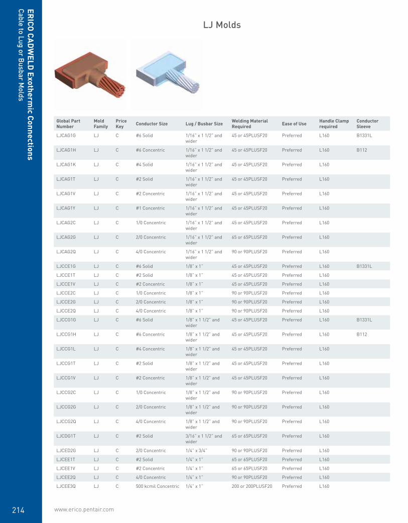
www.erico.pentair.com214
LJ Molds
Global Part Number
Mold Family
Price Key Conductor Size Lug / Busbar Size Welding Material
Required Ease of Use Handle Clamp required
Conductor Sleeve
LJCAG1G LJ C #6 Solid 1/16” x 1 1/2” and wider
45 or 45PLUSF20 Preferred L160 B1331L
LJCAG1H LJ C #6 Concentric 1/16” x 1 1/2” and wider
45 or 45PLUSF20 Preferred L160 B112
LJCAG1K LJ C #4 Solid 1/16” x 1 1/2” and wider
45 or 45PLUSF20 Preferred L160
LJCAG1T LJ C #2 Solid 1/16” x 1 1/2” and wider
45 or 45PLUSF20 Preferred L160
LJCAG1V LJ C #2 Concentric 1/16” x 1 1/2” and wider
45 or 45PLUSF20 Preferred L160
LJCAG1Y LJ C #1 Concentric 1/16” x 1 1/2” and wider
45 or 45PLUSF20 Preferred L160
LJCAG2C LJ C 1/0 Concentric 1/16” x 1 1/2” and wider
45 or 45PLUSF20 Preferred L160
LJCAG2G LJ C 2/0 Concentric 1/16” x 1 1/2” and wider
65 or 65PLUSF20 Preferred L160
LJCAG2Q LJ C 4/0 Concentric 1/16” x 1 1/2” and wider
90 or 90PLUSF20 Preferred L160
LJCCE1G LJ C #6 Solid 1/8” x 1” 45 or 45PLUSF20 Preferred L160 B1331L
LJCCE1T LJ C #2 Solid 1/8” x 1” 45 or 45PLUSF20 Preferred L160
LJCCE1V LJ C #2 Concentric 1/8” x 1” 45 or 45PLUSF20 Preferred L160
LJCCE2C LJ C 1/0 Concentric 1/8” x 1” 90 or 90PLUSF20 Preferred L160
LJCCE2G LJ C 2/0 Concentric 1/8” x 1” 90 or 90PLUSF20 Preferred L160
LJCCE2Q LJ C 4/0 Concentric 1/8” x 1” 90 or 90PLUSF20 Preferred L160
LJCCG1G LJ C #6 Solid 1/8” x 1 1/2” and wider
45 or 45PLUSF20 Preferred L160 B1331L
LJCCG1H LJ C #6 Concentric 1/8” x 1 1/2” and wider
45 or 45PLUSF20 Preferred L160 B112
LJCCG1L LJ C #4 Concentric 1/8” x 1 1/2” and wider
45 or 45PLUSF20 Preferred L160
LJCCG1T LJ C #2 Solid 1/8” x 1 1/2” and wider
45 or 45PLUSF20 Preferred L160
LJCCG1V LJ C #2 Concentric 1/8” x 1 1/2” and wider
45 or 45PLUSF20 Preferred L160
LJCCG2C LJ C 1/0 Concentric 1/8” x 1 1/2” and wider
90 or 90PLUSF20 Preferred L160
LJCCG2G LJ C 2/0 Concentric 1/8” x 1 1/2” and wider
90 or 90PLUSF20 Preferred L160
LJCCG2Q LJ C 4/0 Concentric 1/8” x 1 1/2” and wider
90 or 90PLUSF20 Preferred L160
LJCDG1T LJ C #2 Solid 3/16” x 1 1/2” and wider
65 or 65PLUSF20 Preferred L160
LJCED2G LJ C 2/0 Concentric 1/4” x 3/4” 90 or 90PLUSF20 Preferred L160
LJCEE1T LJ C #2 Solid 1/4” x 1” 65 or 65PLUSF20 Preferred L160
LJCEE1V LJ C #2 Concentric 1/4” x 1” 65 or 65PLUSF20 Preferred L160
LJCEE2Q LJ C 4/0 Concentric 1/4” x 1” 90 or 90PLUSF20 Preferred L160
LJCEE3Q LJ C 500 kcmil Concentric 1/4” x 1” 200 or 200PLUSF20 Preferred L160
ERICO
CADW
ELD Exotherm
ic ConnectionsCable to Lug or Busbar M
olds
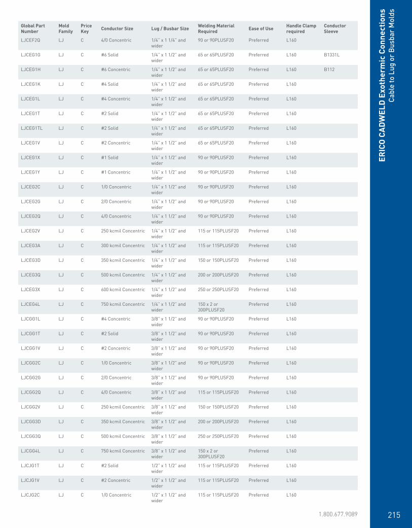
www.erico.pentair.com 1.800.677.9089 215
ERIC
O C
ADW
ELD
Exo
ther
mic
Con
nect
ions
Cabl
e to
Lug
or
Busb
ar M
olds
LJCEF2Q LJ C 4/0 Concentric 1/4” x 1 1/4” and wider
90 or 90PLUSF20 Preferred L160
LJCEG1G LJ C #6 Solid 1/4” x 1 1/2” and wider
65 or 65PLUSF20 Preferred L160 B1331L
LJCEG1H LJ C #6 Concentric 1/4” x 1 1/2” and wider
65 or 65PLUSF20 Preferred L160 B112
LJCEG1K LJ C #4 Solid 1/4” x 1 1/2” and wider
65 or 65PLUSF20 Preferred L160
LJCEG1L LJ C #4 Concentric 1/4” x 1 1/2” and wider
65 or 65PLUSF20 Preferred L160
LJCEG1T LJ C #2 Solid 1/4” x 1 1/2” and wider
65 or 65PLUSF20 Preferred L160
LJCEG1TL LJ C #2 Solid 1/4” x 1 1/2” and wider
65 or 65PLUSF20 Preferred L160
LJCEG1V LJ C #2 Concentric 1/4” x 1 1/2” and wider
65 or 65PLUSF20 Preferred L160
LJCEG1X LJ C #1 Solid 1/4” x 1 1/2” and wider
90 or 90PLUSF20 Preferred L160
LJCEG1Y LJ C #1 Concentric 1/4” x 1 1/2” and wider
90 or 90PLUSF20 Preferred L160
LJCEG2C LJ C 1/0 Concentric 1/4” x 1 1/2” and wider
90 or 90PLUSF20 Preferred L160
LJCEG2G LJ C 2/0 Concentric 1/4” x 1 1/2” and wider
90 or 90PLUSF20 Preferred L160
LJCEG2Q LJ C 4/0 Concentric 1/4” x 1 1/2” and wider
90 or 90PLUSF20 Preferred L160
LJCEG2V LJ C 250 kcmil Concentric 1/4” x 1 1/2” and wider
115 or 115PLUSF20 Preferred L160
LJCEG3A LJ C 300 kcmil Concentric 1/4” x 1 1/2” and wider
115 or 115PLUSF20 Preferred L160
LJCEG3D LJ C 350 kcmil Concentric 1/4” x 1 1/2” and wider
150 or 150PLUSF20 Preferred L160
LJCEG3Q LJ C 500 kcmil Concentric 1/4” x 1 1/2” and wider
200 or 200PLUSF20 Preferred L160
LJCEG3X LJ C 600 kcmil Concentric 1/4” x 1 1/2” and wider
250 or 250PLUSF20 Preferred L160
LJCEG4L LJ C 750 kcmil Concentric 1/4” x 1 1/2” and wider
150 x 2 or 300PLUSF20
Preferred L160
LJCGG1L LJ C #4 Concentric 3/8” x 1 1/2” and wider
90 or 90PLUSF20 Preferred L160
LJCGG1T LJ C #2 Solid 3/8” x 1 1/2” and wider
90 or 90PLUSF20 Preferred L160
LJCGG1V LJ C #2 Concentric 3/8” x 1 1/2” and wider
90 or 90PLUSF20 Preferred L160
LJCGG2C LJ C 1/0 Concentric 3/8” x 1 1/2” and wider
90 or 90PLUSF20 Preferred L160
LJCGG2G LJ C 2/0 Concentric 3/8” x 1 1/2” and wider
90 or 90PLUSF20 Preferred L160
LJCGG2Q LJ C 4/0 Concentric 3/8” x 1 1/2” and wider
115 or 115PLUSF20 Preferred L160
LJCGG2V LJ C 250 kcmil Concentric 3/8” x 1 1/2” and wider
150 or 150PLUSF20 Preferred L160
LJCGG3D LJ C 350 kcmil Concentric 3/8” x 1 1/2” and wider
200 or 200PLUSF20 Preferred L160
LJCGG3Q LJ C 500 kcmil Concentric 3/8” x 1 1/2” and wider
250 or 250PLUSF20 Preferred L160
LJCGG4L LJ C 750 kcmil Concentric 3/8” x 1 1/2” and wider
150 x 2 or 300PLUSF20
Preferred L160
LJCJG1T LJ C #2 Solid 1/2” x 1 1/2” and wider
115 or 115PLUSF20 Preferred L160
LJCJG1V LJ C #2 Concentric 1/2” x 1 1/2” and wider
115 or 115PLUSF20 Preferred L160
LJCJG2C LJ C 1/0 Concentric 1/2” x 1 1/2” and wider
115 or 115PLUSF20 Preferred L160
Global Part Number
Mold Family
Price Key Conductor Size Lug / Busbar Size Welding Material
Required Ease of Use Handle Clamp required
Conductor Sleeve
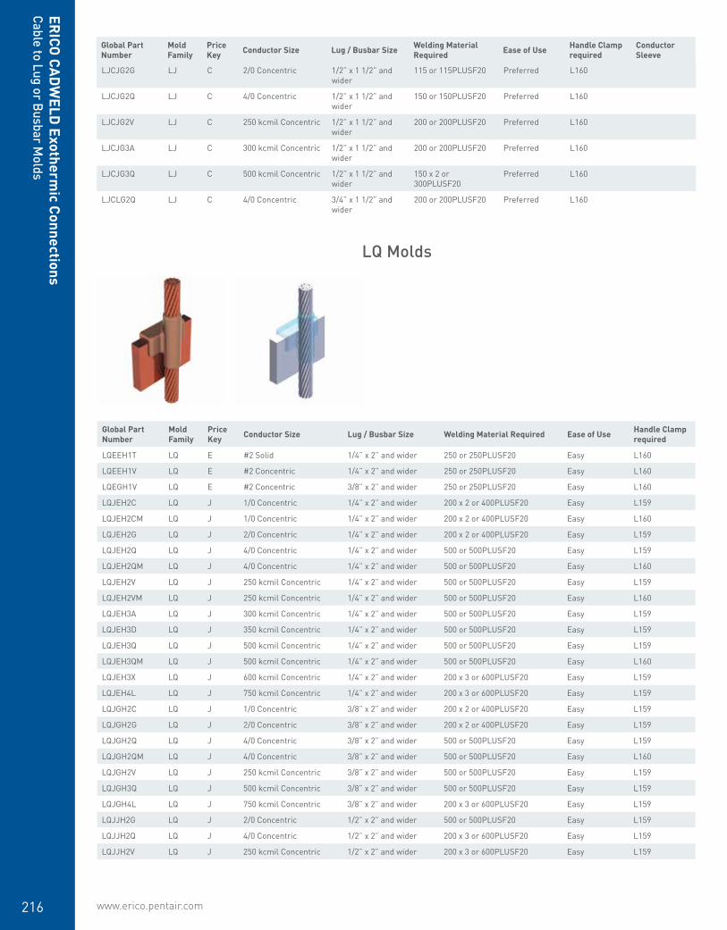
www.erico.pentair.com216
LJCJG2G LJ C 2/0 Concentric 1/2” x 1 1/2” and wider
115 or 115PLUSF20 Preferred L160
LJCJG2Q LJ C 4/0 Concentric 1/2” x 1 1/2” and wider
150 or 150PLUSF20 Preferred L160
LJCJG2V LJ C 250 kcmil Concentric 1/2” x 1 1/2” and wider
200 or 200PLUSF20 Preferred L160
LJCJG3A LJ C 300 kcmil Concentric 1/2” x 1 1/2” and wider
200 or 200PLUSF20 Preferred L160
LJCJG3Q LJ C 500 kcmil Concentric 1/2” x 1 1/2” and wider
150 x 2 or 300PLUSF20
Preferred L160
LJCLG2Q LJ C 4/0 Concentric 3/4” x 1 1/2” and wider
200 or 200PLUSF20 Preferred L160
Global Part Number
Mold Family
Price Key Conductor Size Lug / Busbar Size Welding Material Required Ease of Use Handle Clamp
required
LQEEH1T LQ E #2 Solid 1/4” x 2” and wider 250 or 250PLUSF20 Easy L160
LQEEH1V LQ E #2 Concentric 1/4” x 2” and wider 250 or 250PLUSF20 Easy L160
LQEGH1V LQ E #2 Concentric 3/8” x 2” and wider 250 or 250PLUSF20 Easy L160
LQJEH2C LQ J 1/0 Concentric 1/4” x 2” and wider 200 x 2 or 400PLUSF20 Easy L159
LQJEH2CM LQ J 1/0 Concentric 1/4” x 2” and wider 200 x 2 or 400PLUSF20 Easy L160
LQJEH2G LQ J 2/0 Concentric 1/4” x 2” and wider 200 x 2 or 400PLUSF20 Easy L159
LQJEH2Q LQ J 4/0 Concentric 1/4” x 2” and wider 500 or 500PLUSF20 Easy L159
LQJEH2QM LQ J 4/0 Concentric 1/4” x 2” and wider 500 or 500PLUSF20 Easy L160
LQJEH2V LQ J 250 kcmil Concentric 1/4” x 2” and wider 500 or 500PLUSF20 Easy L159
LQJEH2VM LQ J 250 kcmil Concentric 1/4” x 2” and wider 500 or 500PLUSF20 Easy L160
LQJEH3A LQ J 300 kcmil Concentric 1/4” x 2” and wider 500 or 500PLUSF20 Easy L159
LQJEH3D LQ J 350 kcmil Concentric 1/4” x 2” and wider 500 or 500PLUSF20 Easy L159
LQJEH3Q LQ J 500 kcmil Concentric 1/4” x 2” and wider 500 or 500PLUSF20 Easy L159
LQJEH3QM LQ J 500 kcmil Concentric 1/4” x 2” and wider 500 or 500PLUSF20 Easy L160
LQJEH3X LQ J 600 kcmil Concentric 1/4” x 2” and wider 200 x 3 or 600PLUSF20 Easy L159
LQJEH4L LQ J 750 kcmil Concentric 1/4” x 2” and wider 200 x 3 or 600PLUSF20 Easy L159
LQJGH2C LQ J 1/0 Concentric 3/8” x 2” and wider 200 x 2 or 400PLUSF20 Easy L159
LQJGH2G LQ J 2/0 Concentric 3/8” x 2” and wider 200 x 2 or 400PLUSF20 Easy L159
LQJGH2Q LQ J 4/0 Concentric 3/8” x 2” and wider 500 or 500PLUSF20 Easy L159
LQJGH2QM LQ J 4/0 Concentric 3/8” x 2” and wider 500 or 500PLUSF20 Easy L160
LQJGH2V LQ J 250 kcmil Concentric 3/8” x 2” and wider 500 or 500PLUSF20 Easy L159
LQJGH3Q LQ J 500 kcmil Concentric 3/8” x 2” and wider 500 or 500PLUSF20 Easy L159
LQJGH4L LQ J 750 kcmil Concentric 3/8” x 2” and wider 200 x 3 or 600PLUSF20 Easy L159
LQJJH2G LQ J 2/0 Concentric 1/2” x 2” and wider 500 or 500PLUSF20 Easy L159
LQJJH2Q LQ J 4/0 Concentric 1/2” x 2” and wider 200 x 3 or 600PLUSF20 Easy L159
LQJJH2V LQ J 250 kcmil Concentric 1/2” x 2” and wider 200 x 3 or 600PLUSF20 Easy L159
LQ Molds
ERICO
CADW
ELD Exotherm
ic ConnectionsCable to Lug or Busbar M
olds
Global Part Number
Mold Family
Price Key Conductor Size Lug / Busbar Size Welding Material
Required Ease of Use Handle Clamp required
Conductor Sleeve

www.erico.pentair.com 1.800.677.9089 217
ERIC
O C
ADW
ELD
Exo
ther
mic
Con
nect
ions
Busb
ar to
Bus
bar
Mol
ds
Busbar to Busbar
• Forms a permanent, low resistance connection
• Provides a molecular bond• ERICO CADWELD Exothermic Connections
are rated with the same current capacity as the conductor
• Portable installation equipment with no external source of power required
• Installers can be easily trained to make ERICO CADWELD Exothermic Connections
• Connections are visually inspected
BA Molds
BB Molds
Global Part Number Mold Family Price Key Busbar Size 1 Busbar Size 2 Welding Material Required Ease of Use Handle Clamp
Required
BACCA BA C 1/8” x 1/2” 1/8” x 1/2” 45 or 45PLUSF20 Preferred L160
BACCE BA C 1/8” x 1” 1/8” x 1” 45 or 45PLUSF20 Preferred L160
BACDE BA C 3/16” x 1” 3/16” x 1” 65 or 65PLUSF20 Preferred L160
BACEE BA C 1/4” x 1” 1/4” x 1” 90 or 90PLUSF20 Preferred L160
BACEH BA C 1/4” x 2” 1/4” x 2” 200 or 200PLUSF20 Preferred L160
BADEK BA D 1/4” x 3” 1/4” x 3” 200 x 2 or 400PLUSF20 Preferred L159
BADEM BA D 1/4” x 4” 1/4” x 4” 500 or 500PLUSF20 Preferred L159
BADGK BA D 3/8” x 3” 3/8” x 3” 500 or 500PLUSF20 Preferred L159
Global Part Number Mold Family Price Key Busbar Size 1 Busbar Size 2 Welding Material
Required Ease of Use Handle Clamp Required
BBCCE BB C 1/8” x 1” 1/8” x 1” 90 or 90PLUSF20 Easy L160
BBCEF BB C 1/4” x 1 1/4” 1/4” x 1 1/4” 150 or 150PLUSF20 Easy L160
BBCEG BB C 1/4” x 1 1/2” 1/4” x 1 1/2” 150 or 150PLUSF20 Easy L160
BBDEHEH BB D 1/4” x 2” 1/4” x 2” 250 or 250PLUSF20 Easy L159
BBFEK BB F 1/4” x 3” 1/4” x 3” 200 x 2 or 400PLUSF20 Easy L159

www.erico.pentair.com218
ERICO
CADW
ELD Exotherm
ic ConnectionsBusbar to Busbar M
olds
BM Molds
BQ Molds
Global Part Number Mold Family Price Key Busbar Size 1 Busbar Size 2 Welding Material
Required Ease of Use Handle Clamp Required
BMCCECE BM C 1/8” x 1” 1/8” x 1” 90 or 90PLUSF20 Easy L160
BMCCGCG BM C 1/8” x 1/2” 1/8” x 1/2” 90 or 90PLUSF20 Easy L160
BMCDEDE BM C 3/16” x 1” 3/16” x 1” 90 or 90PLUSF20 Easy L160
BMDCHCH BM D 1/8” x 2” 1/8” x 2” 250 or 250PLUSF20 Easy L159
BMDEKEK BM D 1/4” x 3” and wider 1/4” x 3” 200 x 2 or 400PLUSF20 Easy L159
BMKEMEM BM K 1/4” x 4” and wider 1/4” x 4” 200 x 3 or 600PLUSF20 Easy Frame Included
Global Part Number Mold Family Price Key Busbar Size 1 Busbar Size 2 Welding Material
Required Ease of Use Handle Clamp Required
BQDEHEH BQ D 1/4” x 2” and wider 1/4” x 2” 200 x 2 or 400PLUSF20 Preferred L159
BQDEKEK BQ D 1/4” x 3” 1/4” x 3” 200 x 2 or 400PLUSF20 Preferred L159
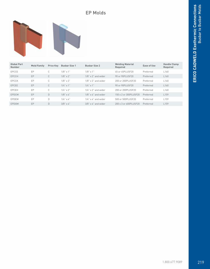
www.erico.pentair.com 1.800.677.9089 219
ERIC
O C
ADW
ELD
Exo
ther
mic
Con
nect
ions
Busb
ar to
Bus
bar
Mol
ds
EP Molds
Global Part Number Mold Family Price Key Busbar Size 1 Busbar Size 2 Welding Material
Required Ease of Use Handle Clamp Required
EPCCE EP C 1/8” x 1” 1/8” x 1” 45 or 45PLUSF20 Preferred L160
EPCCH EP C 1/8” x 2” 1/8” x 2” and wider 90 or 90PLUSF20 Preferred L160
EPCCK EP C 1/8” x 3” 1/8” x 3” and wider 200 or 200PLUSF20 Preferred L160
EPCEE EP C 1/4” x 1” 1/4” x 1” 90 or 90PLUSF20 Preferred L160
EPCEH EP C 1/4” x 2” 1/4” x 2” and wider 200 or 200PLUSF20 Preferred L160
EPDCM EP D 1/8” x 4” 1/8” x 4” and wider 150 x 2 or 300PLUSF20 Preferred L159
EPDEM EP D 1/4” x 4” 1/4” x 4” and wider 500 or 500PLUSF20 Preferred L159
EPDGM EP D 3/8” x 4” 3/8” x 4” and wider 200 x 3 or 600PLUSF20 Preferred L159
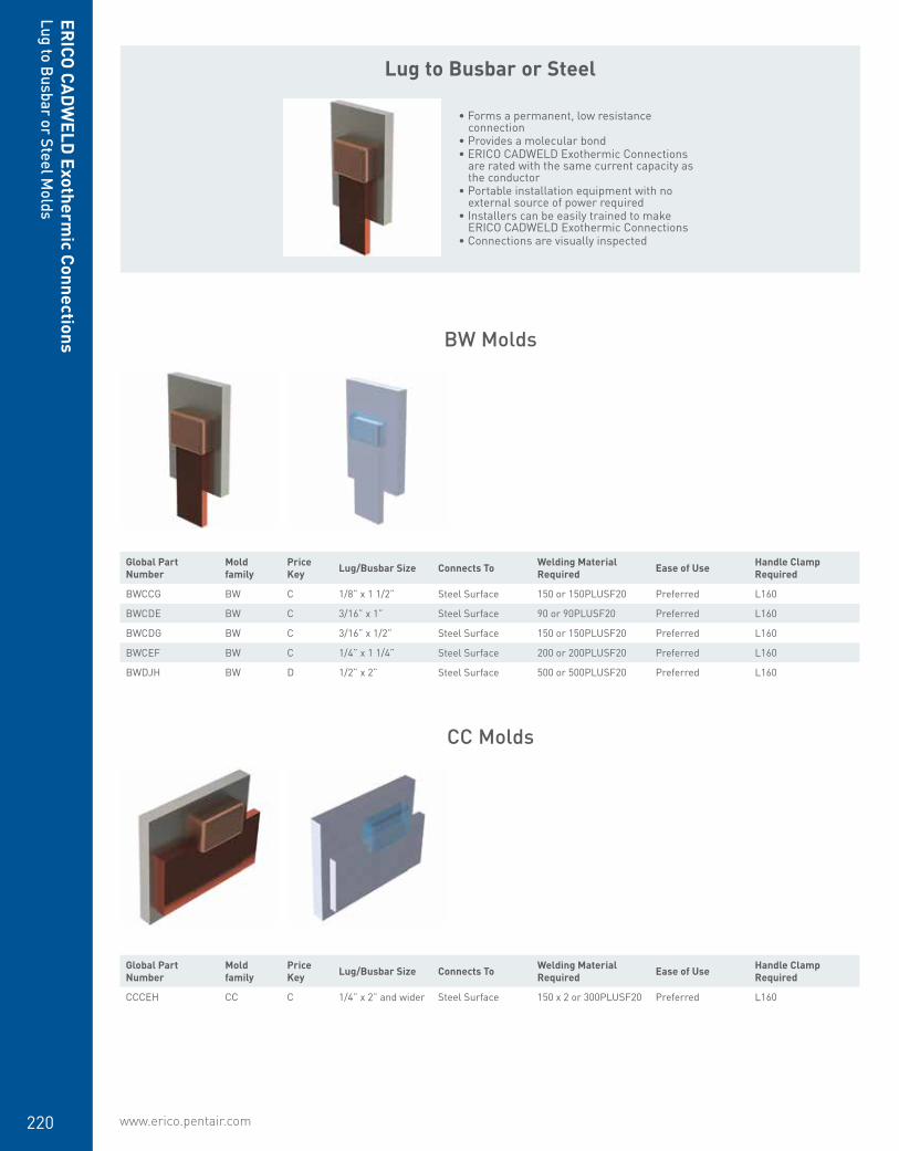
www.erico.pentair.com220
Lug to Busbar or Steel
• Forms a permanent, low resistance connection
• Provides a molecular bond• ERICO CADWELD Exothermic Connections
are rated with the same current capacity as the conductor
• Portable installation equipment with no external source of power required
• Installers can be easily trained to make ERICO CADWELD Exothermic Connections
• Connections are visually inspected
Global Part Number
Mold family
Price Key Lug/Busbar Size Connects To Welding Material
Required Ease of Use Handle Clamp Required
BWCCG BW C 1/8” x 1 1/2” Steel Surface 150 or 150PLUSF20 Preferred L160
BWCDE BW C 3/16” x 1” Steel Surface 90 or 90PLUSF20 Preferred L160
BWCDG BW C 3/16” x 1/2” Steel Surface 150 or 150PLUSF20 Preferred L160
BWCEF BW C 1/4” x 1 1/4” Steel Surface 200 or 200PLUSF20 Preferred L160
BWDJH BW D 1/2” x 2” Steel Surface 500 or 500PLUSF20 Preferred L160
BW Molds
CC Molds
Global Part Number
Mold family
Price Key Lug/Busbar Size Connects To Welding Material
Required Ease of Use Handle Clamp Required
CCCEH CC C 1/4” x 2” and wider Steel Surface 150 x 2 or 300PLUSF20 Preferred L160
ERICO
CADW
ELD Exotherm
ic ConnectionsLug to Busbar or Steel M
olds

www.erico.pentair.com 1.800.677.9089 221
Global Part Number
Mold family
Price Key Lug/Busbar Size Connects To Welding Material
Required Ease of Use Handle Clamp Required
BWCCG BW C 1/8” x 1 1/2” Steel Surface 150 or 150PLUSF20 Preferred L160
BWCDE BW C 3/16” x 1” Steel Surface 90 or 90PLUSF20 Preferred L160
BWCDG BW C 3/16” x 1/2” Steel Surface 150 or 150PLUSF20 Preferred L160
BWCEF BW C 1/4” x 1 1/4” Steel Surface 200 or 200PLUSF20 Preferred L160
BWDJH BW D 1/2” x 2” Steel Surface 500 or 500PLUSF20 Preferred L160
ERIC
O C
ADW
ELD
Exo
ther
mic
Con
nect
ions
Cabl
e to
Reb
ar M
olds
Cable to Rebar
• Forms a permanent, low resistance connection
• Provides a molecular bond• ERICO CADWELD Exothermic Connections
are rated with the same current capacity as the conductor
• Portable installation equipment with no external source of power required
• Installers can be easily trained to make ERICO CADWELD Exothermic Connections
• Connections are visually inspected
CF Molds
RR Molds
Global Part Number
Mold family
Price Key Lug/Busbar Size Connects To Welding Material
Required Ease of Use Handle Clamp Required
CFCDELH CF C 3/16” x 1” Steel Surface 150 or 150PLUSF20 Easy L160
CFDEHRH CF D 1/4” x 2” and wider Steel Surface 150 x 2 or 300PLUSF20 Easy L160
Global Part Number
Mold Family
Price Key
Rebar Size, US Conductor Size Welding Material
Required
Shim /Batting Required
Ease of UseHandle Clamp Required
Conductor Sleeve
RRA521H RR A #4 #6 Concentric 25 or 25PLUSF20 B143B Preferred B112
RRA521K RR A #4 #4 Solid 32 or 32PLUSF20 B143B Preferred
RRA521L RR A #4 #4 Concentric 32 or 32PLUSF20 B143B Preferred
RRA521T RR A #4 #2 Solid 45 or 45PLUSF20 B143A Preferred
RRA521V RR A #4 #2 Concentric 45 or 45PLUSF20 B143A Preferred
RRA521Y RR A #4 #1 Concentric 65 or 65PLUSF20 B143A Preferred
RRA531D RR A #5 #8 Solid 25 or 25PLUSF20 B143B Preferred B1331K
RRA531G RR A #5 #6 Solid 25 or 25PLUSF20 B143B Preferred B1331L
RRA531H RR A #5 #6 Concentric 25 or 25PLUSF20 B143B Preferred B112
RRA531K RR A #5 #4 Solid 32 or 32PLUSF20 B143B Preferred

www.erico.pentair.com222
ERICO
CADW
ELD Exotherm
ic ConnectionsCable to Rebar M
olds
RRA531L RR A #5 #4 Concentric 32 or 32PLUSF20 B143B Preferred
RRA531T RR A #5 #2 Solid 45 or 45PLUSF20 B143A Preferred
RRA531V RR A #5 #2 Concentric 45 or 45PLUSF20 B143A Preferred
RRA531Y RR A #5 #1 Concentric 65 or 65PLUSF20 B143A Preferred
RRA541G RR A #6 #6 Solid 25 or 25PLUSF20 B143B Preferred B1331L
RRA541H RR A #6 #6 Concentric 25 or 25PLUSF20 B143B Preferred B112
RRA541L RR A #6 #4 Concentric 32 or 32PLUSF20 B143B Preferred
RRA541T RR A #6 #2 Solid 45 or 45PLUSF20 B143B Preferred
RRA541V RR A #6 #2 Concentric 45 or 45PLUSF20 B143B Preferred
RRA541Y RR A #6 #1 Concentric 65 or 65PLUSF20 B143B Preferred
RRA551L RR A #7 #4 Concentric 32 or 32PLUSF20 B143B Preferred
RRA551T RR A #7 #2 Solid 45 or 45PLUSF20 B143B Preferred
RRA551V RR A #7 #2 Concentric 45 or 45PLUSF20 B143B Preferred
RRA561L RR A #8 #4 Concentric 32 or 32PLUSF20 B143B Preferred
RRA561T RR A #8 #2 Solid 45 or 45PLUSF20 B143B Preferred
RRA561V RR A #8 #2 Concentric 45 or 45PLUSF20 B143B Preferred
RRA561Y RR A #8 #1 Concentric 65 or 65PLUSF20 B143B Preferred
RRA571T RR A #9 #2 Solid 45 or 45PLUSF20 B143B Preferred
RRA571V RR A #9 #2 Concentric 45 or 45PLUSF20 B143B Preferred
RRH562C RR H #8 1/0 Concentric 90 or 90PLUSF20 B144C Preferred
RRH562G RR H #8 2/0 Concentric 90 or 90PLUSF20 B144C Preferred
RRH562L RR H #8 3/0 Concentric 115 or 115PLUSF20 B144C Preferred
RRH562Q RR H #8 4/0 Concentric 115 or 115PLUSF20 B144C Preferred
RRH562V RR H #8 250 kcmil Concentric
150 or 150PLUSF20 B144C Preferred
RRH572C RR H #9 1/0 Concentric 90 or 90PLUSF20 B144C Preferred
RRH572G RR H #9 2/0 Concentric 90 or 90PLUSF20 B144C Preferred
RRH572L RR H #9 3/0 Concentric 115 or 115PLUSF20 B144C Preferred
RRH572Q RR H #9 4/0 Concentric 115 or 115PLUSF20 B144C Preferred
RRH572V RR H #9 250 kcmil Concentric
150 or 150PLUSF20 B144C Preferred
RRH582C RR H #10 1/0 Concentric 90 or 90PLUSF20 B144C Preferred
RRH582G RR H #10 2/0 Concentric 90 or 90PLUSF20 B144C Preferred
RRH582L RR H #10 3/0 Concentric 115 or 115PLUSF20 B144C Preferred
RRH582Q RR H #10 4/0 Concentric 115 or 115PLUSF20 B144C Preferred
RRH582V RR H #10 250 kcmil Concentric
150 or 150PLUSF20 B144C Preferred
RRH592C RR H #11 1/0 Concentric 90 or 90PLUSF20 B144C Preferred
RRH592G RR H #11 2/0 Concentric 90 or 90PLUSF20 B144C Preferred
RRH592L RR H #11 3/0 Concentric 115 or 115PLUSF20 B144C Preferred
RRH592Q RR H #11 4/0 Concentric 115 or 115PLUSF20 B144C Preferred
RRH592V RR H #11 250 kcmil Concentric
150 or 150PLUSF20 B144C Preferred
RRA581H RR A #10 #6 Concentric 25 or 25PLUSF20 B143B Preferred B112
RRA581T RR A #10 #2 Solid 45 or 45PLUSF20 B143B Preferred
RRA581V RR A #10 #2 Concentric 45 or 45PLUSF20 B143B Preferred
RRA591H RR A #11 #6 Concentric 25 or 25PLUSF20 B143B Preferred B112
RRA591L RR A #11 #4 Concentric 32 or 32PLUSF20 B143B Preferred
RRA591T RR A #11 #2 Solid 45 or 45PLUSF20 B143B Preferred
RRA591V RR A #11 #2 Concentric 45 or 45PLUSF20 B143B Preferred
RRC511H RR C #3 #6 Concentric 25 or 25PLUSF20 Preferred L160
RRC511L RR C #3 #4 Concentric 32 or 32PLUSF20 Preferred L160
RRC511T RR C #3 #2 Solid 45 or 45PLUSF20 Preferred L160
Global Part Number
Mold Family
Price Key
Rebar Size, US Conductor Size Welding Material
Required
Shim /Batting Required
Ease of UseHandle Clamp Required
Conductor Sleeve
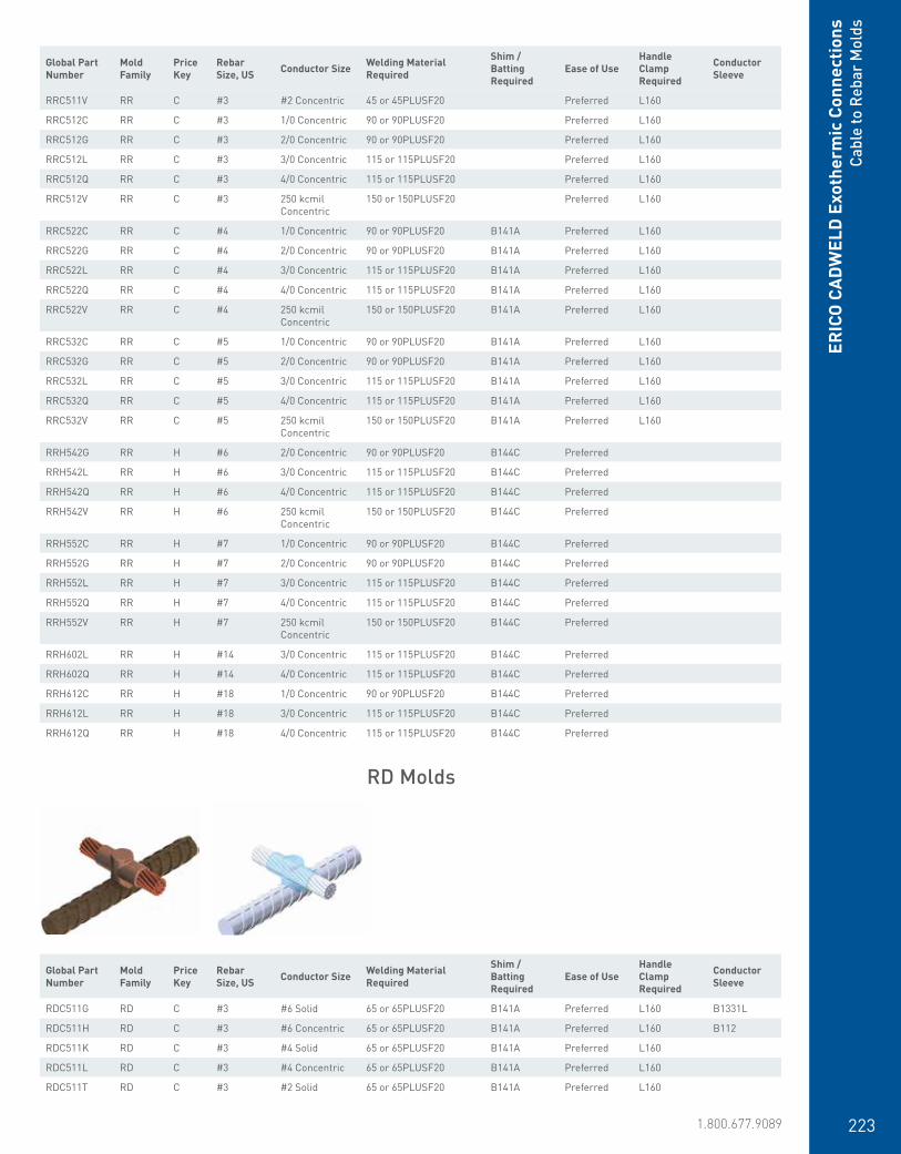
www.erico.pentair.com 1.800.677.9089 223
ERIC
O C
ADW
ELD
Exo
ther
mic
Con
nect
ions
Cabl
e to
Reb
ar M
olds
RRC511V RR C #3 #2 Concentric 45 or 45PLUSF20 Preferred L160
RRC512C RR C #3 1/0 Concentric 90 or 90PLUSF20 Preferred L160
RRC512G RR C #3 2/0 Concentric 90 or 90PLUSF20 Preferred L160
RRC512L RR C #3 3/0 Concentric 115 or 115PLUSF20 Preferred L160
RRC512Q RR C #3 4/0 Concentric 115 or 115PLUSF20 Preferred L160
RRC512V RR C #3 250 kcmil Concentric
150 or 150PLUSF20 Preferred L160
RRC522C RR C #4 1/0 Concentric 90 or 90PLUSF20 B141A Preferred L160
RRC522G RR C #4 2/0 Concentric 90 or 90PLUSF20 B141A Preferred L160
RRC522L RR C #4 3/0 Concentric 115 or 115PLUSF20 B141A Preferred L160
RRC522Q RR C #4 4/0 Concentric 115 or 115PLUSF20 B141A Preferred L160
RRC522V RR C #4 250 kcmil Concentric
150 or 150PLUSF20 B141A Preferred L160
RRC532C RR C #5 1/0 Concentric 90 or 90PLUSF20 B141A Preferred L160
RRC532G RR C #5 2/0 Concentric 90 or 90PLUSF20 B141A Preferred L160
RRC532L RR C #5 3/0 Concentric 115 or 115PLUSF20 B141A Preferred L160
RRC532Q RR C #5 4/0 Concentric 115 or 115PLUSF20 B141A Preferred L160
RRC532V RR C #5 250 kcmil Concentric
150 or 150PLUSF20 B141A Preferred L160
RRH542G RR H #6 2/0 Concentric 90 or 90PLUSF20 B144C Preferred
RRH542L RR H #6 3/0 Concentric 115 or 115PLUSF20 B144C Preferred
RRH542Q RR H #6 4/0 Concentric 115 or 115PLUSF20 B144C Preferred
RRH542V RR H #6 250 kcmil Concentric
150 or 150PLUSF20 B144C Preferred
RRH552C RR H #7 1/0 Concentric 90 or 90PLUSF20 B144C Preferred
RRH552G RR H #7 2/0 Concentric 90 or 90PLUSF20 B144C Preferred
RRH552L RR H #7 3/0 Concentric 115 or 115PLUSF20 B144C Preferred
RRH552Q RR H #7 4/0 Concentric 115 or 115PLUSF20 B144C Preferred
RRH552V RR H #7 250 kcmil Concentric
150 or 150PLUSF20 B144C Preferred
RRH602L RR H #14 3/0 Concentric 115 or 115PLUSF20 B144C Preferred
RRH602Q RR H #14 4/0 Concentric 115 or 115PLUSF20 B144C Preferred
RRH612C RR H #18 1/0 Concentric 90 or 90PLUSF20 B144C Preferred
RRH612L RR H #18 3/0 Concentric 115 or 115PLUSF20 B144C Preferred
RRH612Q RR H #18 4/0 Concentric 115 or 115PLUSF20 B144C Preferred
Global Part Number
Mold Family
Price Key
Rebar Size, US Conductor Size Welding Material
Required
Shim / Batting Required
Ease of UseHandle Clamp Required
Conductor Sleeve
RDC511G RD C #3 #6 Solid 65 or 65PLUSF20 B141A Preferred L160 B1331L
RDC511H RD C #3 #6 Concentric 65 or 65PLUSF20 B141A Preferred L160 B112
RDC511K RD C #3 #4 Solid 65 or 65PLUSF20 B141A Preferred L160
RDC511L RD C #3 #4 Concentric 65 or 65PLUSF20 B141A Preferred L160
RDC511T RD C #3 #2 Solid 65 or 65PLUSF20 B141A Preferred L160
RD Molds
Global Part Number
Mold Family
Price Key
Rebar Size, US Conductor Size Welding Material
Required
Shim /Batting Required
Ease of UseHandle Clamp Required
Conductor Sleeve

www.erico.pentair.com224
RDC521G RD C #4 #6 Solid 65 or 65PLUSF20 B141A Preferred L160 B1331L
RDC521H RD C #4 #6 Concentric 65 or 65PLUSF20 B141A Preferred L160 B112
RDC521K RD C #4 #4 Solid 65 or 65PLUSF20 B141A Preferred L160
RDC521L RD C #4 #4 Concentric 65 or 65PLUSF20 B141A Preferred L160
RDC521T RD C #4 #2 Solid 65 or 65PLUSF20 B141A Preferred L160
RDC521V RD C #4 #2 Concentric 90 or 90PLUSF20 B141A Preferred L160
RDC531G RD C #5 #6 Solid 65 or 65PLUSF20 B141A Preferred L160 B1331L
RDC531H RD C #5 #6 Concentric 65 or 65PLUSF20 B141A Preferred L160 B112
RDC531K RD C #5 #4 Solid 65 or 65PLUSF20 B141A Preferred L160
RDC531L RD C #5 #4 Concentric 65 or 65PLUSF20 B141A Preferred L160
RDC531T RD C #5 #2 Solid 90 or 90PLUSF20 B141A Preferred L160
RDC531V RD C #5 #2 Concentric 90 or 90PLUSF20 B141A Preferred L160
RDH541H RD H #6 #6 Concentric 65 or 65PLUSF20 B144C Preferred B112
RDH541L RD H #6 #4 Concentric 65 or 65PLUSF20 B144C Preferred
RDH541T RD H #6 #2 Solid 90 or 90PLUSF20 B144C Preferred
RDH541V RD H #6 #2 Concentric 90 or 90PLUSF20 B144C Preferred
RDH542C RD H #6 1/0 Concentric 115 or 115PLUSF20 B144C Preferred
RDH542G RD H #6 2/0 Concentric 115 or 115PLUSF20 B144C Preferred
RDH542Q RD H #6 4/0 Concentric 150 or 150PLUSF20 B144C Preferred
RDH542V RD H #6 250 kcmil Concentric
150 or 150PLUSF20 B144C Preferred
RDH551G RD H #7 #6 Solid 65 or 65PLUSF20 B144C Preferred B1331L
RDH551H RD H #7 #6 Concentric 65 or 65PLUSF20 B144C Preferred B112
RDH551L RD H #7 #4 Concentric 65 or 65PLUSF20 B144C Preferred
RDH551T RD H #7 #2 Solid 90 or 90PLUSF20 B144C Preferred
RDH551V RD H #7 #2 Concentric 90 or 90PLUSF20 B144C Preferred
RDH552C RD H #7 1/0 Concentric 115 or 115PLUSF20 B144C Preferred
RDH552G RD H #7 2/0 Concentric 115 or 115PLUSF20 B144C Preferred
RDH552Q RD H #7 4/0 Concentric 150 or 150PLUSF20 B144C Preferred
RDH552V RD H #7 250 kcmil Concentric
150 or 150PLUSF20 B144C Preferred
RDH561L RD H #8 #4 Concentric 65 or 65PLUSF20 B144C Preferred
RDH561T RD H #8 #2 Solid 90 or 90PLUSF20 B144C Preferred
RDH561V RD H #8 #2 Concentric 90 or 90PLUSF20 B144C Preferred
RDH561Y RD H #8 #1 Concentric 90 or 90PLUSF20 B144C Preferred
RDH562C RD H #8 1/0 Concentric 115 or 115PLUSF20 B144C Preferred
RDH562G RD H #8 2/0 Concentric 115 or 115PLUSF20 B144C Preferred
RDH562Q RD H #8 4/0 Concentric 150 or 150PLUSF20 B144C Preferred
RDH562V RD H #8 250 kcmil Concentric
150 or 150PLUSF20 B144C Preferred
RDH571T RD H #9 #2 Solid 90 or 90PLUSF20 B144C Preferred
RDH571V RD H #9 #2 Concentric 90 or 90PLUSF20 B144C Preferred
RDH572C RD H #9 1/0 Concentric 115 or 115PLUSF20 B144C Preferred
RDH572G RD H #9 2/0 Concentric 115 or 115PLUSF20 B144C Preferred
RDH572Q RD H #9 4/0 Concentric 150 or 150PLUSF20 B144C Preferred
RDH572V RD H #9 250 kcmil Concentric
150 or 150PLUSF20 B144C Preferred
RDH581T RD H #10 #2 Solid 90 or 90PLUSF20 B144C Preferred
RDH581V RD H #10 #2 Concentric 90 or 90PLUSF20 B144C Preferred
RDH582C RD H #10 1/0 Concentric 115 or 115PLUSF20 B144C Preferred
RDH582G RD H #10 2/0 Concentric 115 or 115PLUSF20 B144C Preferred
ERICO
CADW
ELD Exotherm
ic ConnectionsCable to Rebar M
olds
Global Part Number
Mold Family
Price Key
Rebar Size, US Conductor Size Welding Material
Required
Shim / Batting Required
Ease of UseHandle Clamp Required
Conductor Sleeve
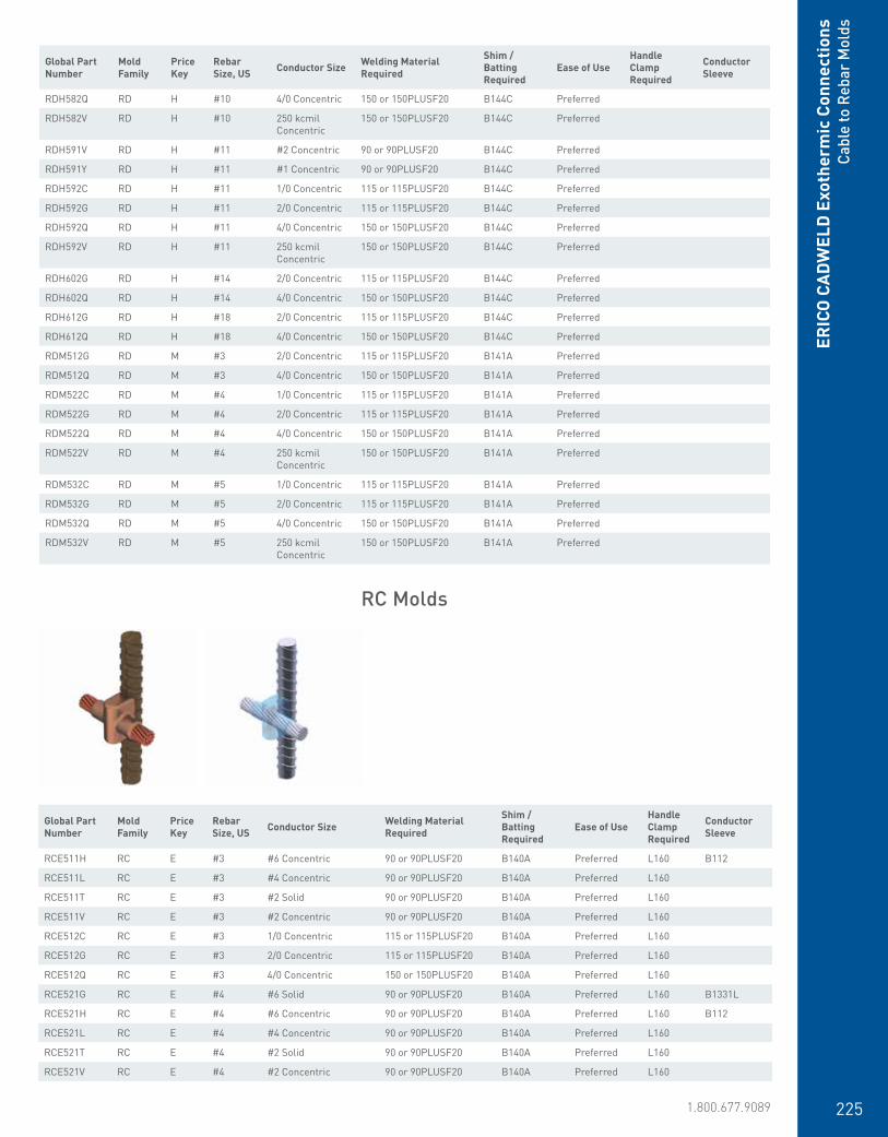
www.erico.pentair.com 1.800.677.9089 225
ERIC
O C
ADW
ELD
Exo
ther
mic
Con
nect
ions
Cabl
e to
Reb
ar M
olds
RDH582Q RD H #10 4/0 Concentric 150 or 150PLUSF20 B144C Preferred
RDH582V RD H #10 250 kcmil Concentric
150 or 150PLUSF20 B144C Preferred
RDH591V RD H #11 #2 Concentric 90 or 90PLUSF20 B144C Preferred
RDH591Y RD H #11 #1 Concentric 90 or 90PLUSF20 B144C Preferred
RDH592C RD H #11 1/0 Concentric 115 or 115PLUSF20 B144C Preferred
RDH592G RD H #11 2/0 Concentric 115 or 115PLUSF20 B144C Preferred
RDH592Q RD H #11 4/0 Concentric 150 or 150PLUSF20 B144C Preferred
RDH592V RD H #11 250 kcmil Concentric
150 or 150PLUSF20 B144C Preferred
RDH602G RD H #14 2/0 Concentric 115 or 115PLUSF20 B144C Preferred
RDH602Q RD H #14 4/0 Concentric 150 or 150PLUSF20 B144C Preferred
RDH612G RD H #18 2/0 Concentric 115 or 115PLUSF20 B144C Preferred
RDH612Q RD H #18 4/0 Concentric 150 or 150PLUSF20 B144C Preferred
RDM512G RD M #3 2/0 Concentric 115 or 115PLUSF20 B141A Preferred
RDM512Q RD M #3 4/0 Concentric 150 or 150PLUSF20 B141A Preferred
RDM522C RD M #4 1/0 Concentric 115 or 115PLUSF20 B141A Preferred
RDM522G RD M #4 2/0 Concentric 115 or 115PLUSF20 B141A Preferred
RDM522Q RD M #4 4/0 Concentric 150 or 150PLUSF20 B141A Preferred
RDM522V RD M #4 250 kcmil Concentric
150 or 150PLUSF20 B141A Preferred
RDM532C RD M #5 1/0 Concentric 115 or 115PLUSF20 B141A Preferred
RDM532G RD M #5 2/0 Concentric 115 or 115PLUSF20 B141A Preferred
RDM532Q RD M #5 4/0 Concentric 150 or 150PLUSF20 B141A Preferred
RDM532V RD M #5 250 kcmil Concentric
150 or 150PLUSF20 B141A Preferred
RC Molds
Global Part Number
Mold Family
Price Key
Rebar Size, US Conductor Size Welding Material
Required
Shim /Batting Required
Ease of UseHandle Clamp Required
Conductor Sleeve
RCE511H RC E #3 #6 Concentric 90 or 90PLUSF20 B140A Preferred L160 B112
RCE511L RC E #3 #4 Concentric 90 or 90PLUSF20 B140A Preferred L160
RCE511T RC E #3 #2 Solid 90 or 90PLUSF20 B140A Preferred L160
RCE511V RC E #3 #2 Concentric 90 or 90PLUSF20 B140A Preferred L160
RCE512C RC E #3 1/0 Concentric 115 or 115PLUSF20 B140A Preferred L160
RCE512G RC E #3 2/0 Concentric 115 or 115PLUSF20 B140A Preferred L160
RCE512Q RC E #3 4/0 Concentric 150 or 150PLUSF20 B140A Preferred L160
RCE521G RC E #4 #6 Solid 90 or 90PLUSF20 B140A Preferred L160 B1331L
RCE521H RC E #4 #6 Concentric 90 or 90PLUSF20 B140A Preferred L160 B112
RCE521L RC E #4 #4 Concentric 90 or 90PLUSF20 B140A Preferred L160
RCE521T RC E #4 #2 Solid 90 or 90PLUSF20 B140A Preferred L160
RCE521V RC E #4 #2 Concentric 90 or 90PLUSF20 B140A Preferred L160
Global Part Number
Mold Family
Price Key
Rebar Size, US Conductor Size Welding Material
Required
Shim / Batting Required
Ease of UseHandle Clamp Required
Conductor Sleeve

www.erico.pentair.com226
ERICO
CADW
ELD Exotherm
ic ConnectionsCable to Rebar M
olds
RCE521Y RC E #4 #1 Concentric 115 or 115PLUSF20 B140A Preferred L160
RCE522C RC E #4 1/0 Concentric 115 or 115PLUSF20 B140A Preferred L160
RCE522G RC E #4 2/0 Concentric 115 or 115PLUSF20 B140A Preferred L160
RCE522Q RC E #4 4/0 Concentric 150 or 150PLUSF20 B140A Preferred L160
RCE522V RC E #4 250 kcmil Concentric 150 or 150PLUSF20 B140A Preferred L160
RCE531G RC E #5 #6 Solid 90 or 90PLUSF20 B140A Preferred L160 B1331L
RCE531H RC E #5 #6 Concentric 90 or 90PLUSF20 B140A Preferred L160 B112
RCE531L RC E #5 #4 Concentric 90 or 90PLUSF20 B140A Preferred L160
RCE531T RC E #5 #2 Solid 90 or 90PLUSF20 B140A Preferred L160
RCE531V RC E #5 #2 Concentric 90 or 90PLUSF20 B140A Preferred L160
RCE532C RC E #5 1/0 Concentric 115 or 115PLUSF20 B140A Preferred L160
RCE532G RC E #5 2/0 Concentric 115 or 115PLUSF20 B140A Preferred L160
RCE532Q RC E #5 4/0 Concentric 150 or 150PLUSF20 B140A Preferred L160
RCE532V RC E #5 250 kcmil Concentric 150 or 150PLUSF20 B140A Preferred L160
RCE541H RC E #6 #6 Concentric 90 or 90PLUSF20 B144B Preferred L160 B112
RCE541L RC E #6 #4 Concentric 90 or 90PLUSF20 B144B Preferred L160
RCE541T RC E #6 #2 Solid 90 or 90PLUSF20 B144B Preferred L160
RCE541V RC E #6 #2 Concentric 90 or 90PLUSF20 B144B Preferred L160
RCE542C RC E #6 1/0 Concentric 115 or 115PLUSF20 B144B Preferred L160
RCE542G RC E #6 2/0 Concentric 115 or 115PLUSF20 B144B Preferred L160
RCE542Q RC E #6 4/0 Concentric 150 or 150PLUSF20 B144B Preferred L160
RCE551H RC E #7 #6 Concentric 90 or 90PLUSF20 B144B Preferred L160 B112
RCE551L RC E #7 #4 Concentric 90 or 90PLUSF20 B144B Preferred L160
RCE551T RC E #7 #2 Solid 90 or 90PLUSF20 B144B Preferred L160
RCE551V RC E #7 #2 Concentric 90 or 90PLUSF20 B144B Preferred L160
RCE552C RC E #7 1/0 Concentric 115 or 115PLUSF20 B144B Preferred L160
RCE552G RC E #7 2/0 Concentric 115 or 115PLUSF20 B144B Preferred L160
RCE552Q RC E #7 4/0 Concentric 150 or 150PLUSF20 B144B Preferred L160
RCE561H RC E #8 #6 Concentric 90 or 90PLUSF20 B144B Preferred L160 B112
RCE561K RC E #8 #4 Solid 90 or 90PLUSF20 B144B Preferred L160
RCE561T RC E #8 #2 Solid 90 or 90PLUSF20 B144B Preferred L160
RCE561V RC E #8 #2 Concentric 90 or 90PLUSF20 B144B Preferred L160
RCE562C RC E #8 1/0 Concentric 115 or 115PLUSF20 B144B Preferred L160
RCE562G RC E #8 2/0 Concentric 115 or 115PLUSF20 B144B Preferred L160
RCE562Q RC E #8 4/0 Concentric 150 or 150PLUSF20 B144B Preferred L160
RCE571T RC E #9 #2 Solid 90 or 90PLUSF20 B144B Preferred L160
RCE571V RC E #9 #2 Concentric 90 or 90PLUSF20 B144B Preferred L160
RCE572C RC E #9 1/0 Concentric 115 or 115PLUSF20 B144B Preferred L160
RCE572G RC E #9 2/0 Concentric 115 or 115PLUSF20 B144B Preferred L160
RCE572Q RC E #9 4/0 Concentric 150 or 150PLUSF20 B144B Preferred L160
RCE581V RC E #10 #2 Concentric 90 or 90PLUSF20 B144B Preferred L160
RCE582C RC E #10 1/0 Concentric 115 or 115PLUSF20 B144B Preferred L160
RCE582G RC E #10 2/0 Concentric 115 or 115PLUSF20 B144B Preferred L160
RCE582Q RC E #10 4/0 Concentric 150 or 150PLUSF20 B144B Preferred L160
RCE591G RC E #11 #6 Solid 90 or 90PLUSF20 B144B Preferred L160 B1331L
RCE591V RC E #11 #2 Concentric 90 or 90PLUSF20 B144B Preferred L160
RCE591Y RC E #11 #1 Concentric 115 or 115PLUSF20 B144B Preferred L160
RCE592C RC E #11 1/0 Concentric 115 or 115PLUSF20 B144B Preferred L160
RCE592G RC E #11 2/0 Concentric 115 or 115PLUSF20 B144B Preferred L160
RCE592Q RC E #11 4/0 Concentric 150 or 150PLUSF20 B144B Preferred L160
RCE602G RC E #14 2/0 Concentric 115 or 115PLUSF20 B144B Preferred L160
Global Part Number
Mold Family
Price Key
Rebar Size, US Conductor Size Welding Material
Required
Shim /Batting Required
Ease of UseHandle Clamp Required
Conductor Sleeve
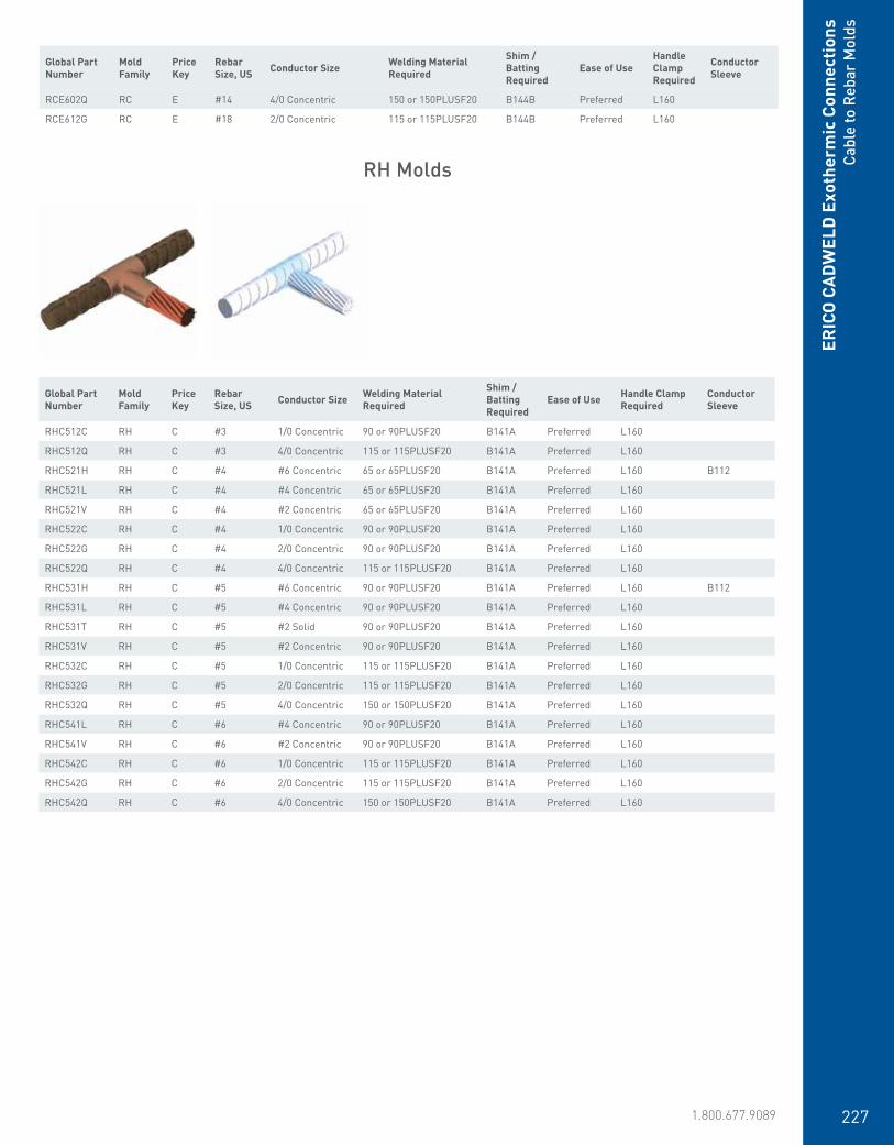
www.erico.pentair.com 1.800.677.9089 227
ERIC
O C
ADW
ELD
Exo
ther
mic
Con
nect
ions
Cabl
e to
Reb
ar M
olds
RH Molds
Global Part Number
Mold Family
Price Key
Rebar Size, US Conductor Size Welding Material
Required
Shim / Batting Required
Ease of Use Handle Clamp Required
Conductor Sleeve
RHC512C RH C #3 1/0 Concentric 90 or 90PLUSF20 B141A Preferred L160
RHC512Q RH C #3 4/0 Concentric 115 or 115PLUSF20 B141A Preferred L160
RHC521H RH C #4 #6 Concentric 65 or 65PLUSF20 B141A Preferred L160 B112
RHC521L RH C #4 #4 Concentric 65 or 65PLUSF20 B141A Preferred L160
RHC521V RH C #4 #2 Concentric 65 or 65PLUSF20 B141A Preferred L160
RHC522C RH C #4 1/0 Concentric 90 or 90PLUSF20 B141A Preferred L160
RHC522G RH C #4 2/0 Concentric 90 or 90PLUSF20 B141A Preferred L160
RHC522Q RH C #4 4/0 Concentric 115 or 115PLUSF20 B141A Preferred L160
RHC531H RH C #5 #6 Concentric 90 or 90PLUSF20 B141A Preferred L160 B112
RHC531L RH C #5 #4 Concentric 90 or 90PLUSF20 B141A Preferred L160
RHC531T RH C #5 #2 Solid 90 or 90PLUSF20 B141A Preferred L160
RHC531V RH C #5 #2 Concentric 90 or 90PLUSF20 B141A Preferred L160
RHC532C RH C #5 1/0 Concentric 115 or 115PLUSF20 B141A Preferred L160
RHC532G RH C #5 2/0 Concentric 115 or 115PLUSF20 B141A Preferred L160
RHC532Q RH C #5 4/0 Concentric 150 or 150PLUSF20 B141A Preferred L160
RHC541L RH C #6 #4 Concentric 90 or 90PLUSF20 B141A Preferred L160
RHC541V RH C #6 #2 Concentric 90 or 90PLUSF20 B141A Preferred L160
RHC542C RH C #6 1/0 Concentric 115 or 115PLUSF20 B141A Preferred L160
RHC542G RH C #6 2/0 Concentric 115 or 115PLUSF20 B141A Preferred L160
RHC542Q RH C #6 4/0 Concentric 150 or 150PLUSF20 B141A Preferred L160
Global Part Number
Mold Family
Price Key
Rebar Size, US Conductor Size Welding Material
Required
Shim /Batting Required
Ease of UseHandle Clamp Required
Conductor Sleeve
RCE602Q RC E #14 4/0 Concentric 150 or 150PLUSF20 B144B Preferred L160
RCE612G RC E #18 2/0 Concentric 115 or 115PLUSF20 B144B Preferred L160

www.erico.pentair.com228
RJ Molds
Global Part Number
Mold Family
Price Key
Rebar Size, US Conductor Size Welding Material
Required
Shim /Batting Required
Ease of UseHandle Clamp Required
Conductor Sleeve
RJC522C RJ C #4 1/0 Concentric 115 or 115PLUSF20 B140A Preferred L160
RJC522G RJ C #4 2/0 Concentric 115 or 115PLUSF20 B140A Preferred L160
RJC522Q RJ C #4 4/0 Concentric 150 or 150PLUSF20 B140A Preferred L160
RJC522V RJ C #4 250 kcmil Concentric
150 or 150PLUSF20 B140A Preferred L160
RJC531H RJ C #5 #6 Concentric 45 or 45PLUSF20 B140A Preferred L160 B112
RJC531K RJ C #5 #4 Solid 65 or 65PLUSF20 B140A Preferred L160
RJC531L RJ C #5 #4 Concentric 65 or 65PLUSF20 B140A Preferred L160
RJC531T RJ C #5 #2 Solid 65 or 65PLUSF20 B140A Preferred L160
RJC531V RJ C #5 #2 Concentric 65 or 65PLUSF20 B140A Preferred L160
RJC531Y RJ C #5 #1 Concentric 90 or 90PLUSF20 B140A Preferred L160
RJC532C RJ C #5 1/0 Concentric 115 or 115PLUSF20 B140A Preferred L160
RJC532G RJ C #5 2/0 Concentric 115 or 115PLUSF20 B140A Preferred L160
RJC532Q RJ C #5 4/0 Concentric 150 or 150PLUSF20 B140A Preferred L160
RJC532V RJ C #5 250 kcmil Concentric
150 or 150PLUSF20 B140A Preferred L160
RJC541H RJ C #6 #6 Concentric 45 or 45PLUSF20 B140A Preferred L160 B112
RJC541L RJ C #6 #4 Concentric 65 or 65PLUSF20 B140A Preferred L160
RJC541T RJ C #6 #2 Solid 65 or 65PLUSF20 B140A Preferred L160
RJC541V RJ C #6 #2 Concentric 65 or 65PLUSF20 B140A Preferred L160
RJC542C RJ C #6 1/0 Concentric 115 or 115PLUSF20 B140A Preferred L160
RJC542G RJ C #6 2/0 Concentric 115 or 115PLUSF20 B140A Preferred L160
RJC542Q RJ C #6 4/0 Concentric 150 or 150PLUSF20 B140A Preferred L160
RJC542V RJ C #6 250 kcmil Concentric
150 or 150PLUSF20 B140A Preferred L160
RJE551L RJ E #7 #4 Concentric 65 or 65PLUSF20 B144A Preferred L160
RJE551T RJ E #7 #2 Solid 65 or 65PLUSF20 B144A Preferred L160
RJE551V RJ E #7 #2 Concentric 65 or 65PLUSF20 B144A Preferred L160
RJE552C RJ E #7 1/0 Concentric 115 or 115PLUSF20 B144B Preferred L160
RJE552G RJ E #7 2/0 Concentric 115 or 115PLUSF20 B144B Preferred L160
RJE552Q RJ E #7 4/0 Concentric 150 or 150PLUSF20 B144B Preferred L160
RJE561L RJ E #8 #4 Concentric 65 or 65PLUSF20 B144A Preferred L160
RJE561T RJ E #8 #2 Solid 65 or 65PLUSF20 B144A Preferred L160
RJE561V RJ E #8 #2 Concentric 65 or 65PLUSF20 B144A Preferred L160
RJE562C RJ E #8 1/0 Concentric 115 or 115PLUSF20 B144B Preferred L160
RJE562Q RJ E #8 4/0 Concentric 150 or 150PLUSF20 B144B Preferred L160
RJE562V RJ E #8 250 kcmil Concentric
150 or 150PLUSF20 B144B Preferred L160
RJE571L RJ E #9 #4 Concentric 65 or 65PLUSF20 B144A Preferred L160
RJE571T RJ E #9 #2 Solid 65 or 65PLUSF20 B144A Preferred L160
RJE571V RJ E #9 #2 Concentric 65 or 65PLUSF20 B144A Preferred L160
RJE572C RJ E #9 1/0 Concentric 115 or 115PLUSF20 B144B Preferred L160
ERICO
CADW
ELD Exotherm
ic ConnectionsCable to Rebar M
olds

www.erico.pentair.com 1.800.677.9089 229
ERIC
O C
ADW
ELD
Exo
ther
mic
Con
nect
ions
Cabl
e to
Gro
und
Rece
ptac
le o
r Gr
ound
Pla
te M
olds
RJE572G RJ E #9 2/0 Concentric 115 or 115PLUSF20 B144B Preferred L160
RJE572Q RJ E #9 4/0 Concentric 150 or 150PLUSF20 B144B Preferred L160
RJE572V RJ E #9 250 kcmil Concentric
150 or 150PLUSF20 B144B Preferred L160
RJE581T RJ E #10 #2 Solid 65 or 65PLUSF20 B144A Preferred L160
RJE581V RJ E #10 #2 Concentric 65 or 65PLUSF20 B144A Preferred L160
RJE582C RJ E #10 1/0 Concentric 115 or 115PLUSF20 B144B Preferred L160
RJE582G RJ E #10 2/0 Concentric 115 or 115PLUSF20 B144B Preferred L160
RJE582Q RJ E #10 4/0 Concentric 150 or 150PLUSF20 B144B Preferred L160
RJE582V RJ E #10 250 kcmil Concentric
150 or 150PLUSF20 B144B Preferred L160
RJE591V RJ E #11 #2 Concentric 65 or 65PLUSF20 B144A Preferred L160
RJE592C RJ E #11 1/0 Concentric 115 or 115PLUSF20 B144B Preferred L160
RJE592G RJ E #11 2/0 Concentric 115 or 115PLUSF20 B144B Preferred L160
RJE592Q RJ E #11 4/0 Concentric 150 or 150PLUSF20 B144B Preferred L160
RJE592V RJ E #11 250 kcmil Concentric
150 or 150PLUSF20 B144B Preferred L160
RJE602C RJ E #14 1/0 Concentric 115 or 115PLUSF20 B144B Preferred L160
Global Part Number Mold Family Price
Key Conductor Size Ground Receptacle Welding Material Required Ease of Use Handle Clamp
RAC2C RA C 1/0 Concentric B165 Grounding Receptacle 150 or 150PLUSF20 Preferred L160
RAC2G RA C 2/0 Concentric B165 Grounding Receptacle 150 or 150PLUSF20 Preferred L160
RAC2Q RA C 4/0 Concentric B165 Grounding Receptacle 150 or 150PLUSF20 Preferred L160
RA Molds
Cable to Ground Receptacle or Ground Plate
• Forms a permanent, low resistance connection
• Provides a molecular bond• ERICO CADWELD Exothermic Connections
are rated with the same current capacity as the conductor
• Portable installation equipment with no external source of power required
• Installers can be easily trained to make ERICO CADWELD Exothermic Connections
• Connections are visually inspected
Global Part Number
Mold Family
Price Key
Rebar Size, US Conductor Size Welding Material
Required
Shim /Batting Required
Ease of UseHandle Clamp Required
Conductor Sleeve

www.erico.pentair.com230
RB Molds
Global Part Number
Mold Family Price Key Conductor Size Ground Receptacle Welding Material Required Ease of Use Handle Clamp
RBC2G RB C 2/0 Concentric B165 Grounding Receptacle 150 or 150PLUSF20 Preferred L160
RBC2Q RB C 4/0 Concentric B165 Grounding Receptacle 200 or 200PLUSF20 Preferred L160
ERICO
CADW
ELD Exotherm
ic ConnectionsCable to Ground Receptacle or Ground Plate M
olds
GB/GR Molds
Global Part Number
Mold Family
Price Key Conductor Size
Ground Plate/Grounding Receptacle
Ground Rod Diameter, Nominal
Ground Rod Diameter, Actual
Ground Rod Type
Welding Material Required
Ease of Use Handle Clamp
GBJGR 162CR2
GB/GR J 1/0 Concentric B166 Grounding Receptacle
5/8” 0.563” Copper-bonded
200 x 2 or 200PLUSF20
Preferred L159
GBJGR 162QR1
GB/GR J 4/0 Concentric B165 Grounding Receptacle
5/8” 0.563” Copper-bonded
200 x 2 or 200PLUSF20
Preferred L159
GBJGR 182CR1
GB/GR J 1/0 Concentric B165 Grounding Receptacle
3/4” 0.682” Copper-bonded
200 x 2 or 200PLUSF20
Preferred L159
GBJGR 182CR2
GB/GR J 1/0 Concentric B166 Grounding Receptacle
3/4” 0.682” Copper-bonded
200 x 2 or 200PLUSF20
Preferred L159
GBJGR 182GR1
GB/GR J 2/0 Concentric B165 Grounding Receptacle
3/4” 0.682” Copper-bonded
200 x 2 or 200PLUSF20
Preferred L159
GBJGR 182GR2
GB/GR J 2/0 Concentric B166 Grounding Receptacle
3/4” 0.682” Copper-bonded
200 x 2 or 200PLUSF20
Preferred L159
GBJGR182QR1
GB/GR J 4/0 Concentric B165 Grounding Receptacle
3/4” 0.682” Copper-bonded
200 x 2 or 200PLUSF20
Preferred L159
GBJGR 332GR1
GB/GR J 2/0 Concentric B165 Grounding Receptacle
3/4” 0.750” Steel 200 x 2 or 200PLUSF20
Preferred L159
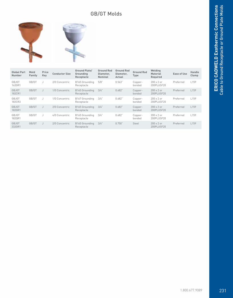
www.erico.pentair.com 1.800.677.9089 231
ERIC
O C
ADW
ELD
Exo
ther
mic
Con
nect
ions
Cabl
e to
Gro
und
Rece
ptac
le o
r Gr
ound
Pla
te M
olds
GB/GT Molds
Global Part Number
Mold Family
Price Key Conductor Size
Ground Plate/Grounding Receptacle
Ground Rod Diameter, Nominal
Ground Rod Diameter, Actual
Ground Rod Type
Welding Material Required
Ease of Use Handle Clamp
GBJGT 162GR1
GB/GT J 2/0 Concentric B165 Grounding Receptacle
5/8” 0.563” Copper-bonded
200 x 2 or 200PLUSF20
Preferred L159
GBJGT 182CR1
GB/GT J 1/0 Concentric B165 Grounding Receptacle
3/4” 0.682” Copper-bonded
200 x 2 or 200PLUSF20
Preferred L159
GBJGT 182CR3
GB/GT J 1/0 Concentric B167 Grounding Receptacle
3/4” 0.682” Copper-bonded
200 x 2 or 200PLUSF20
Preferred L159
GBJGT 182GR1
GB/GT J 2/0 Concentric B165 Grounding Receptacle
3/4” 0.682” Copper-bonded
200 x 2 or 200PLUSF20
Preferred L159
GBJGT182QR1
GB/GT J 4/0 Concentric B165 Grounding Receptacle
3/4” 0.682” Copper-bonded
200 x 2 or 200PLUSF20
Preferred L159
GBJGT 332GR1
GB/GT J 2/0 Concentric B165 Grounding Receptacle
3/4” 0.750” Steel 200 x 2 or 200PLUSF20
Preferred L159

www.erico.pentair.com232
ERICO
CADW
ELD Exotherm
ic ConnectionsCopper or Steel Stud to Steel Surface M
olds
Global Part Number Mold Family Price Key Stud Type Connects To Welding Material
Required Ease of Use Handle Clamp required
HVC12 HV C 3/8” Steel Stud Steel Surface 45 or 45PLUSF20 Easy L160
HVC12CU HV C 3/8” Copper Stud Steel Surface 90 or 90PLUSF20 Easy L160
HVC14CU HV C 1/2” Copper Stud Steel Surface 115 or 115PLUSF20 Easy L160
HVC18 HV C 3/4” Steel Stud Steel Surface 150 or 150PLUSF20 Easy L160
HVC31CU HV C 5/8” Copper Stud Steel Surface 150 or 150PLUSF20 Easy L160
HVD37CU HV D 1” Copper Stud Steel Surface 200 x 2 or 400PLUSF20 Easy L159
Global Part Number Mold Family Price Key Stud Type Connects To Welding Material
Required Ease of Use Handle Clamp required
HXC10 HX C 1/4” Steel Stud Steel Surface 25 or 25PLUSF20 Easy L160
HXC12 HX C 3/8” Steel Stud Steel Surface 45 or 45PLUSF20 Easy L160
HXC14 HX C 1/2” Steel Stud Steel Surface 65 or 65PLUSF20 Easy L160
HXC14CU HX C 1/2” Copper Stud Steel Surface 115 or 115PLUSF20 Easy L160
HXC16 HX C 5/8” Steel Stud Steel Surface 90 or 90PLUSF20 Easy L160
HXC22 HX C 1” Steel Stud Steel Surface 150 x 2 or 300PLUSF20 Easy L160
HV Molds
HX Molds
Copper or Steel Stud to Steel Surface
• Forms a permanent, low resistance connection
• Provides a molecular bond• ERICO CADWELD Exothermic Connections
are rated with the same current capacity as the conductor
• Portable installation equipment with no external source of power required
• Installers can be easily trained to make ERICO CADWELD Exothermic Connections
• Connections are visually inspected

www.erico.pentair.com 1.800.677.9089 233
ERIC
O C
ADW
ELD
Exo
ther
mic
Con
nect
ions
Addi
tiona
l Mol
ds
Cable to Cable
SVEase of Use: DIFFICULTMold Split: V
PREase of Use: EASYMold Split: V
TVEase of Use: DIFFICULTMold Split: V
YREase of Use: EASYMold Split: H
SEEase of Use: DIFFICULTMold Split: V
PBEase of Use: DIFFICULTMold Split: V
TCEase of Use: DIFFICULTMold Split: V
YDEase of Use: DIFFICULTMold Split: V
SCEase of Use: PREFERREDMold Split: -
PAEase of Use: EASYMold Split: -
TLEase of Use: DIFFICULTMold Split: V
YCEase of Use: DIFFICULTMold Split: V
PPEase of Use: PREFERREDMold Split: -
PDEase of Use: DIFFICULTMold Split: V
TFEase of Use: DIFFICULTMold Split: V
XGEase of Use: DIFFICULTMold Split: -
TDEase of Use: DIFFICULTMold Split: -
XCEase of Use: DIFFICULTMold Split: V
Additional Molds
The CADWELD connection styles presented in the additional mold section are “non-catalog” offerings.These connection styles and others are available when standard connections do not meet the installation requirements.Connections are identified with an ease of use and a mold split identifier. Ease of use categories include: preferred, easy, difficult and most difficult.
If possible, efforts should be made to use preferred or easy to use connection styles.Mold split identifies molds that have a vertically split crucible (V). Those without a designation do not have a vertically split crucible.For additional information and/or assistance in ordering non-catalog connection styles, please contact your ERICO-CADWELD representative.

www.erico.pentair.com234
Cable to Ground Rods
Cable to Steel Studs to Steel Surface
GFEase of Use: PREFERREDMold Split: V
GSEase of Use: PREFERREDMold Split: V
GPEase of Use: DIFFICULTMold Split: V
GMEase of Use: EASYMold Split: V
GCEase of Use: DIFFICULTMold Split: V
DQEase of Use: PREFERREDMold Split: V
VLEase of Use: PREFERREDMold Split: V
HXEase of Use: PREFERREDMold Split: V
GHEase of Use: DIFFICULTMold Split: V
GDEase of Use: DIFFICULTMold Split: V
GQEase of Use: EASYMold Split: V
VAEase of Use: PREFERREDMold Split: V
HVEase of Use: PREFERREDMold Split: V
GGEase of Use: PREFERREDMold Split: -
GVEase of Use: PREFERREDMold Split: V
GWEase of Use: EASYMold Split: V
GJEase of Use: PREFERREDMold Split: -
GXEase of Use: DIFFICULTMold Split: V
ERICO
CADW
ELD Exotherm
ic ConnectionsAdditional M
olds

www.erico.pentair.com 1.800.677.9089 235
Cable to Rebar
Cable to Lug or Busbar
RGEase of Use: PREFERREDMold Split: V
LBEase of Use: PREFERREDMold Split: V
RTEase of Use: EASYMold Split: V
LVEase of Use: PREFERREDMold Split: V
DREase of Use: EASYMold Split: V
MEEase of Use: EASYMold Split: V
RLEase of Use: EASYMold Split: V
LLEase of Use: PREFERREDMold Split: V
LFEase of Use: DIFFICULTMold Split: V
LHEase of Use: DIFFICULTMold Split: -
RFEase of Use: EASYMold Split: V
LXEase of Use: EASYMold Split: V
RMEase of Use: EASYMold Split: V
LSEase of Use: EASYMold Split: V
LEEase of Use: EASYMold Split: V
REEase of Use: EASYMold Split: V
LDEase of Use: DIFFICULTMold Split: -
RWEase of Use: EASYMold Split: V
LWEase of Use: PREFERREDMold Split: -
LKEase of Use: EASYMold Split: -
RVEase of Use: EASYMold Split: V
MGEase of Use: EASYMold Split: -
RQEase of Use: EASYMold Split: V
LMEase of Use: PREFERREDMold Split: -
LGEase of Use: DIFFICULTMold Split: -
ERIC
O C
ADW
ELD
Exo
ther
mic
Con
nect
ions
Addi
tiona
l Mol
ds
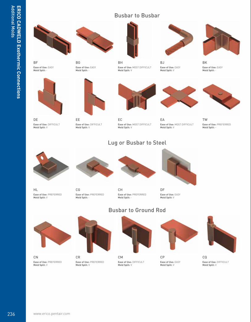
www.erico.pentair.com236
Busbar to Busbar
Busbar to Ground Rod
Lug or Busbar to Steel
BFEase of Use: EASYMold Split: -
CNEase of Use: PREFERREDMold Split: V
HLEase of Use: PREFERREDMold Split: V
DEEase of Use: DIFFICULTMold Split: V
BKEase of Use: EASYMold Split: -
CQEase of Use: DIFFICULTMold Split: V
TWEase of Use: PREFERREDMold Split: -
BHEase of Use: MOST DIFFICULTMold Split: V
CMEase of Use: DIFFICULTMold Split: V
CHEase of Use: PREFERREDMold Split: -
ECEase of Use: MOST DIFFICULTMold Split: V
BGEase of Use: EASYMold Split: -
CREase of Use: PREFERREDMold Split: V
CGEase of Use: PREFERREDMold Split: -
EEEase of Use: DIFFICULTMold Split: V
BJEase of Use: EASYMold Split: V
CPEase of Use: EASYMold Split: V
DFEase of Use: EASYMold Split: V
EAEase of Use: MOST DIFFICULTMold Split: V
ERICO
CADW
ELD Exotherm
ic ConnectionsAdditional M
olds

www.erico.pentair.com 1.800.677.9089 237
ERICO CADWELDWELDING MATERIAL, TOOLS + ACCESSORIES

www.erico.pentair.com 1.800.677.9089238
ERICO
CADW
ELD Exotherm
ic ConnectionsW
elding Materials
ERICO CADWELD Welding Material, F20
• Mixture consists mainly of copper oxide and aluminum
• Primarily used in grounding and bonding applications
• Welding material is in the top of the tube and starting material is in the bottom of the tube
• Packaged by size in plastic tubes with clear caps
• Tubes packaged in plastic boxes along with metal disks
• Each welded connection uses a single disk• Non-explosive• Not subject to spontaneous ignition• See specific ERICO CADWELD connection
details to determine welding material requirements
Featured Highlights
Part Number Standard Packaging Quantity
115 10 pc15 20 pc150 10 pc200 10 pc25 20 pc250 10 pc32 20 pc45 20 pc500 10 pc65 20 pc90 10 pc
ERICO CADWELD PLUS Welding Material, F20
• Mixture consists mainly of copper oxide and aluminum
• Primarily used in grounding and bonding applications
• Integrated welding material package• Color coding by size for easy identification• Electronic ignition• No starting material required• Non-explosive• Not subject to spontaneous ignition• See specific ERICO CADWELD connection
details to determine welding material requirements
Featured Highlights
Part Number Color Code Ring Certifications Standard Packaging Quantity
115PLUSF20 Orange cULus 10 pc1250PLUSF20 None 5 pc150PLUSF20 Dark Blue cULus 10 pc15PLUSF20 Black cULus 20 pc200PLUSF20 Yellow cULus 10 pc

www.erico.pentair.com 1.800.677.9089 239
ERIC
O C
ADW
ELD
Exo
ther
mic
Con
nect
ions
Wel
ding
Mat
eria
ls
Part Number Color Code Ring Certifications Standard Packaging Quantity
250PLUSF20 Purple cULus 10 pc25PLUSF20 Red cULus 20 pc300PLUSF20 Light Green cULus 10 pc32PLUSF20 White cULus 20 pc400PLUSF20 Brown 10 pc45PLUSF20 Light Blue cULus 20 pc500PLUSF20 Light Brown 10 pc600PLUSF20 White 5 pc65PLUSF20 Dark Green cULus 20 pc750PLUSF20 White 5 pc90PLUSF20 Gray cULus 10 pc
ERICO CADWELD EXOLON Welding Material, F20
• Mixture consists mainly of copper oxide and aluminum
• Primarily used in grounding and bonding applications
• Designed for applications where low smoke emission is required
• Welding material packaged in tubes without starting material
• Tubes packaged with filters and igniters• Electronic ignition• Each weld uses one igniter• Not subject to spontaneous ignition• See specific ERICO CADWELD connection
details to determine welding material requirements
Featured Highlights
Part Number Certifications
XL115 cULusXL15 cULusXL150 cULusXL200 cULusXL25 cULusXL250 cULusXL300 cULusXL32 cULusXL400 cULusXL45 cULusXL500 cULusXL600XL65 cULusXL750XL90 cULus
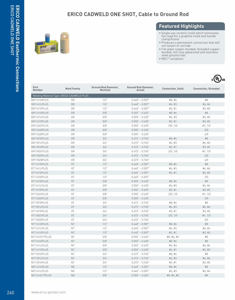
www.erico.pentair.com240
ERICO
CADW
ELD Exotherm
ic ConnectionsERICO CADW
ELD ONE SH
OT
ERICO CADWELD ONE SHOT, Cable to Ground Rod
• Single use ceramic mold which eliminates the need for a graphite mold and handle clamp/frame
• Produces a permanent connection that will not loosen or corrode
• Fits plain copper-bonded, threaded copper-bonded, full-size galvanized and stainless steel ground rods
• NEC® compliant
Featured Highlights
Part Number Mold Family Ground Rod Diameter,
NominalGround Rod Diameter,
Actual Connection, Solid Connection, Stranded
Welding Material Type: ERICO CADWELD PLUSGR1141GPLUS GR 1/2” 0.440” – 0.507” #8, #6 #8GR1141LPLUS GR 1/2” 0.440” – 0.507” #4, #3 #6, #4GR1141VPLUS GR 1/2” 0.440” – 0.507” #2, #1 #3, #2GR1161GPLUS GR 5/8” 0.555” – 0.635” #8, #6 #8GR1161LPLUS GR 5/8” 0.555” – 0.635” #4, #3 #6, #4GR1161VPLUS GR 5/8” 0.555” – 0.635” #2, #1 #3, #2GR1162CPLUS GR 5/8” 0.555” – 0.635” 2/0, 1/0 #1, 1/0GR1162GPLUS GR 5/8” 0.555” – 0.635” 2/0GR1162QPLUS GR 5/8” 0.555” – 0.635” 4/0GR1181GPLUS GR 3/4” 0.673” – 0.765” #8, #6 #8GR1181LPLUS GR 3/4” 0.673” – 0.765” #4, #3 #6, #4GR1181VPLUS GR 3/4” 0.673” – 0.765” #2, #1 #3, #2GR1182CPLUS GR 3/4” 0.673” – 0.765” 2/0, 1/0 #1, 1/0GR1182GPLUS GR 3/4” 0.673” – 0.765” 2/0GR1182QPLUS GR 3/4” 0.673” – 0.765” 4/0GT1141GPLUS GT 1/2” 0.440” – 0.507” #8, #6 #8GT1141LPLUS GT 1/2” 0.440” – 0.507” #4, #3 #6, #4GT1141VPLUS GT 1/2” 0.440” – 0.507” #2, #1 #3, #2GT1142GPLUS GT 1/2” 0.440” – 0.507” 2/0GT1161GPLUS GT 5/8” 0.555” – 0.635” #8, #6 #8GT1161LPLUS GT 5/8” 0.555” – 0.635” #4, #3 #6, #4GT1161VPLUS GT 5/8” 0.555” – 0.635” #2, #1 #3, #2GT1162CPLUS GT 5/8” 0.555” – 0.635” 2/0, 1/0 #1, 1/0GT1162GPLUS GT 5/8” 0.555” – 0.635” 2/0GT1181GPLUS GT 3/4” 0.673” – 0.765” #8, #6 #8GT1181LPLUS GT 3/4” 0.673” – 0.765” #4, #3 #6, #4GT1181VPLUS GT 3/4” 0.673” – 0.765” #2, #1 #3, #2GT1182CPLUS GT 3/4” 0.673” – 0.765” 2/0, 1/0 #1, 1/0GT1182GPLUS GT 3/4” 0.673” – 0.765” 2/0NT1141GPLUS NT 1/2” 0.440” – 0.507” #8, #6 #8NT1141LPLUS NT 1/2” 0.440” – 0.507” #4, #3 #6, #4NT1141VPLUS NT 1/2” 0.440” – 0.507” #2, #1 #3, #2NT1161G1TPLUS NT 5/8” 0.555” – 0.635” #8, #6, #2 #8NT1161GPLUS NT 5/8” 0.555” – 0.635” #8, #6 #8NT1161LPLUS NT 5/8” 0.555” – 0.635” #4, #3 #6, #4NT1161VPLUS NT 5/8” 0.555” – 0.635” #2, #1 #3, #2NT1181GPLUS NT 3/4” 0.673” – 0.765” #8, #6 #8NT1181LPLUS NT 3/4” 0.673” – 0.765” #4, #3 #6, #4NT1181VPLUS NT 3/4” 0.673” – 0.765” #2, #1 #3, #2NX1141GPLUS NX 1/2” 0.440” – 0.507” #8, #6 #8NX1141LPLUS NX 1/2” 0.440” – 0.507” #4, #3 #6, #4NX1161G1TPLUS NX 5/8” 0.555” – 0.635” #8, #6, #2 #8
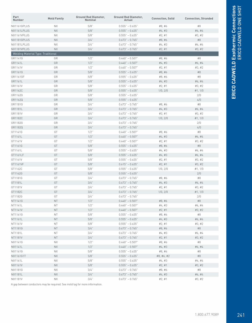
www.erico.pentair.com 1.800.677.9089 241
ERIC
O C
ADW
ELD
Exo
ther
mic
Con
nect
ions
ERIC
O CA
DWEL
D ON
E SH
OT
Part Number Mold Family Ground Rod Diameter,
NominalGround Rod Diameter,
Actual Connection, Solid Connection, Stranded
NX1161GPLUS NX 5/8” 0.555” – 0.635” #8, #6 #8NX1161LPLUS NX 5/8” 0.555” – 0.635” #4, #3 #6, #4NX1161VPLUS NX 5/8” 0.555” – 0.635” #2, #1 #3, #2NX1181GPLUS NX 3/4” 0.673” – 0.765” #8, #6 #8NX1181LPLUS NX 3/4” 0.673” – 0.765” #4, #3 #6, #4NX1181VPLUS NX 3/4” 0.673” – 0.765” #2, #1 #3, #2
Welding Material Type: TraditionalGR1141G GR 1/2” 0.440” – 0.507” #8, #6 #8GR1141L GR 1/2” 0.440” – 0.507” #4, #3 #6, #4GR1141V GR 1/2” 0.440” – 0.507” #2, #1 #3, #2GR1161G GR 5/8” 0.555” – 0.635” #8, #6 #8GR1161GF GR 5/8” 0.555” – 0.635” #8, #6 #8GR1161L GR 5/8” 0.555” – 0.635” #4, #3 #6, #4GR1161V GR 5/8” 0.555” – 0.635” #2, #1 #3, #2GR1162C GR 5/8” 0.555” – 0.635” 1/0, 2/0 #1, 1/0GR1162G GR 5/8” 0.555” – 0.635” 2/0GR1162Q GR 5/8” 0.555” – 0.635” 4/0GR1181G GR 3/4” 0.673” – 0.765” #8, #6 #8GR1181L GR 3/4” 0.673” – 0.765” #4, #3 #6, #4GR1181V GR 3/4” 0.673” – 0.765” #2, #1 #3, #2GR1182C GR 3/4” 0.673” – 0.765” 1/0, 2/0 #1, 1/0GR1182G GR 3/4” 0.673” – 0.765” 2/0GR1182Q GR 3/4” 0.673” – 0.765” 4/0GT1141G GT 1/2” 0.440” – 0.507” #8, #6 #8GT1141L GT 1/2” 0.440” – 0.507” #4, #3 #6, #4GT1141V GT 1/2” 0.440” – 0.507” #2, #1 #3, #2GT1161G GT 5/8” 0.555” – 0.635” #8, #6 #8GT1161L GT 5/8” 0.555” – 0.635” #4, #3 #6, #4GT1161LF GT 5/8” 0.555” – 0.635” #4, #3 #6, #4GT1161V GT 5/8” 0.555” – 0.635” #2, #1 #3, #2GT1161VF GT 5/8” 0.615” – 0.635” #2, #1 #3, #2GT1162C GT 5/8” 0.555” – 0.635” 1/0, 2/0 #1, 1/0GT1162G GT 5/8” 0.555” – 0.635” 2/0GT1181G GT 3/4” 0.673” – 0.765” #8, #6 #8GT1181L GT 3/4” 0.673” – 0.765” #4, #3 #6, #4GT1181V GT 3/4” 0.673” – 0.765” #2, #1 #3, #2GT1182C GT 3/4” 0.673” – 0.765” 1/0, 2/0 #1, 1/0GT1182G GT 3/4” 0.673” – 0.765” 2/0NT1141G NT 1/2” 0.440” – 0.507” #8, #6 #8NT1141L NT 1/2” 0.440” – 0.507” #4, #3 #6, #4NT1141V NT 1/2” 0.440” – 0.507” #2, #1 #3, #2NT1161G NT 5/8” 0.555” – 0.635” #8, #6 #8NT1161L NT 5/8” 0.555” – 0.635” #4, #3 #6, #4NT1161V NT 5/8” 0.555” – 0.635” #2, #1 #3, #2NT1181G NT 3/4” 0.673” – 0.765” #8, #6 #8NT1181L NT 3/4” 0.673” – 0.765” #4, #3 #6, #4NT1181V NT 3/4” 0.673” – 0.765” #2, #1 #3, #2NX1141G NX 1/2” 0.440” – 0.507” #8, #6 #8NX1141L NX 1/2” 0.440” – 0.507” #4, #3 #6, #4NX1161G NX 5/8” 0.555” – 0.635” #8, #6 #8NX1161G1T NX 5/8” 0.555” – 0.635” #8, #6, #2 #8NX1161L NX 5/8” 0.555” – 0.635” #4, #3 #6, #4NX1161V NX 5/8” 0.555” – 0.635” #2, #1 #3, #2NX1181G NX 3/4” 0.673” – 0.765” #8, #6 #8NX1181L NX 3/4” 0.673” – 0.765” #4, #3 #6, #4NX1181V NX 3/4” 0.673” – 0.765” #2, #1 #3, #2
A gap between conductors may be required. See mold tag for more information.

www.erico.pentair.com242
ERICO
CADW
ELD Exotherm
ic ConnectionsLugs
ERICO CADWELD ONE SHOT, Cable to Cable
• Single use ceramic mold which eliminates the need for a graphite mold and handle clamp/frame
• Produces a permanent connection that will not loosen or corrode
• NEC® compliant
Featured Highlights
Part Number Mold Family Connection, Solid Connection, Stranded
Welding Material Type: ERICO CADWELD PLUSPG11LPLUS PG #4, #3 #6, #4
Welding Material Type: TraditionalPG11L PG #3, #4 #6, #4PG11V PG #2, #1 #3, #2
1 Hole Lug
• Provides an efficient bolting surface for grounding and power applications
• Electrolytic grade copper• For use with ERICO CADWELD type LA
connections only
Featured Highlights
T
L
Material: CopperFinish: TinnedType: NEMA®
Part Number Length Width Thickness A Hole Size Equivalent Conductor Size
B101AA 1.250” 0.500” 0.062” 0.310” 0.281” 39 kcmilB101CE 1.940” 1.000” 0.125” 0.500” 0.438” 159 kcmilB101DE 1.940” 1.000” 0.188” 0.563” 0.563” 239 kcmilB101EE 2.190” 1.000” 0.250” 0.625” 0.563” 318 kcmilB101EG 2.500” 1.500” 0.250” 0.750” 0.688” 477 kcmilB101GG 2.750” 1.500” 0.375” 0.750” 0.688” 716 kcmilB101GH 3.380” 2.000” 0.375” 1.000” 0.688” 955 kcmilB101JH 3.380” 2.000” 0.500” 1.000” 0.563” 1,273 kcmilB101QQ 1.941” 1.000” 0.125” 0.470” 0.410” 159 kcmilPBB101EG 2.500” 1.500” 0.250” 0.750” 0.688” 477 kcmilPBB101GH 3.380” 2.000” 0.375” 1.000” 0.688” 955 kcmil
For sizes not listed, contact ERICO.

www.erico.pentair.com 1.800.677.9089 243
ERIC
O C
ADW
ELD
Exo
ther
mic
Con
nect
ions
Lugs
2 Hole Lug
• Provides an efficient bolting surface for grounding and power applications
• Electrolytic grade copper• For use with ERICO CADWELD type LA
connections only
Featured Highlights
T
L
Material: CopperFinish: TinnedType: NEMA®
Part Number Length Width Thickness A B Hole Size Equivalent Conductor Size
B102CE 4.000” 1.0” 0.125” 0.625” 1.75” 0.563” 159 kcmilB102DE 4.000” 1.0” 0.188” 0.625” 1.75” 0.563” 239 kcmilB102EE 4.125” 1.0” 0.250” 0.625” 1.75” 0.563” 318 kcmilB102EG 4.125” 1.5” 0.250” 0.625” 1.75” 0.563” 477 kcmilB102EH 4.125” 2.0” 0.250” 0.625” 1.75” 0.563” 637 kcmilB102GG 4.750” 1.5” 0.375” 0.625” 1.75” 0.563” 716 kcmilB102GH 4.750” 2.0” 0.375” 0.625” 1.75” 0.563” 955 kcmilB102JH 5.250” 2.0” 0.500” 0.625” 1.75” 0.563” 1,273 kcmil
For sizes not listed, contact ERICO.
4 Hole Lug
• Provides an efficient bolting surface for grounding and power applications
• Electrolytic grade copper• For use with ERICO CADWELD type LA
connections only
Featured Highlights
T
L
Material: CopperFinish: TinnedType: NEMA®
Part Number Length Width Thickness A B Hole Size Equivalent Conductor Size
B104EK 4.50” 3” 0.250” 0.625” 1.75” 0.563” 955 kcmilB104GK 4.75” 3” 0.375” 0.625” 1.75” 0.563” 1,432 kcmilB104JK 4.75” 3” 0.500” 0.625” 1.75” 0.563” 1,910 kcmil
For sizes not listed, contact ERICO.
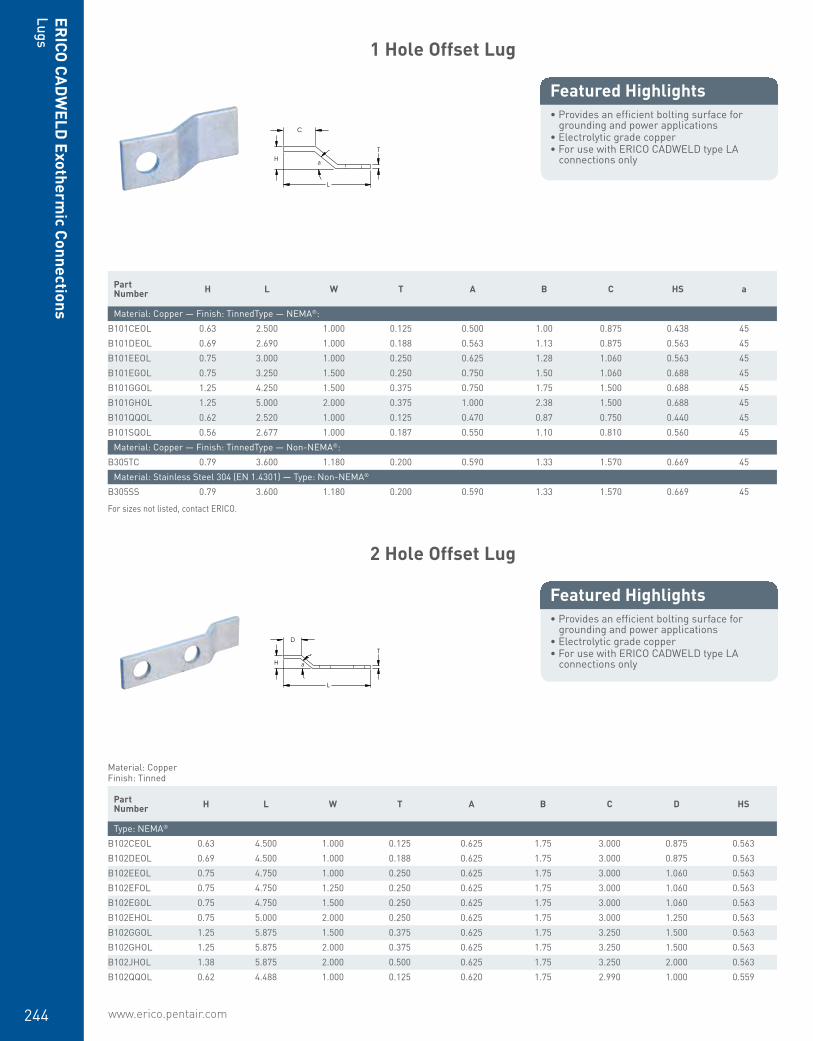
www.erico.pentair.com244
ERICO
CADW
ELD Exotherm
ic ConnectionsLugs
1 Hole Offset Lug
• Provides an efficient bolting surface for grounding and power applications
• Electrolytic grade copper• For use with ERICO CADWELD type LA
connections only
Featured Highlights
C
H T
a
L
Part Number H L W T A B C HS a
Material: Copper — Finish: TinnedType — NEMA®:B101CEOL 0.63 2.500 1.000 0.125 0.500 1.00 0.875 0.438 45B101DEOL 0.69 2.690 1.000 0.188 0.563 1.13 0.875 0.563 45B101EEOL 0.75 3.000 1.000 0.250 0.625 1.28 1.060 0.563 45B101EGOL 0.75 3.250 1.500 0.250 0.750 1.50 1.060 0.688 45B101GGOL 1.25 4.250 1.500 0.375 0.750 1.75 1.500 0.688 45B101GHOL 1.25 5.000 2.000 0.375 1.000 2.38 1.500 0.688 45B101QQOL 0.62 2.520 1.000 0.125 0.470 0.87 0.750 0.440 45B101SQOL 0.56 2.677 1.000 0.187 0.550 1.10 0.810 0.560 45
Material: Copper — Finish: TinnedType — Non-NEMA®:B305TC 0.79 3.600 1.180 0.200 0.590 1.33 1.570 0.669 45
Material: Stainless Steel 304 (EN 1.4301) — Type: Non-NEMA®
B305SS 0.79 3.600 1.180 0.200 0.590 1.33 1.570 0.669 45
For sizes not listed, contact ERICO.
2 Hole Offset Lug
• Provides an efficient bolting surface for grounding and power applications
• Electrolytic grade copper• For use with ERICO CADWELD type LA
connections only
Featured Highlights
L
H a
D
T
Material: CopperFinish: Tinned
Part Number H L W T A B C D HS
Type: NEMA®
B102CEOL 0.63 4.500 1.000 0.125 0.625 1.75 3.000 0.875 0.563B102DEOL 0.69 4.500 1.000 0.188 0.625 1.75 3.000 0.875 0.563B102EEOL 0.75 4.750 1.000 0.250 0.625 1.75 3.000 1.060 0.563B102EFOL 0.75 4.750 1.250 0.250 0.625 1.75 3.000 1.060 0.563B102EGOL 0.75 4.750 1.500 0.250 0.625 1.75 3.000 1.060 0.563B102EHOL 0.75 5.000 2.000 0.250 0.625 1.75 3.000 1.250 0.563B102GGOL 1.25 5.875 1.500 0.375 0.625 1.75 3.250 1.500 0.563B102GHOL 1.25 5.875 2.000 0.375 0.625 1.75 3.250 1.500 0.563B102JHOL 1.38 5.875 2.000 0.500 0.625 1.75 3.250 2.000 0.563B102QQOL 0.62 4.488 1.000 0.125 0.620 1.75 2.990 1.000 0.559
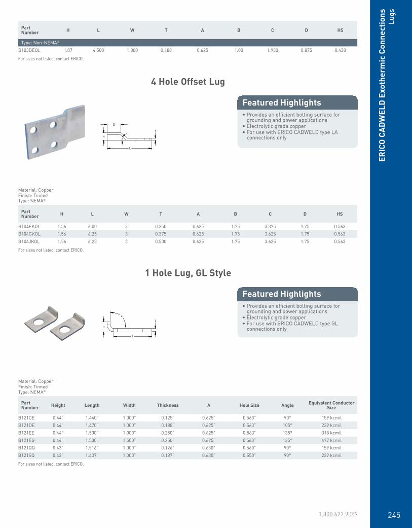
www.erico.pentair.com 1.800.677.9089 245
ERIC
O C
ADW
ELD
Exo
ther
mic
Con
nect
ions
Lugs
Part Number H L W T A B C D HS
Type: Non-NEMA®
B103DEOL 1.07 4.500 1.000 0.188 0.625 1.00 1.930 0.875 0.438
For sizes not listed, contact ERICO.
4 Hole Offset Lug
• Provides an efficient bolting surface for grounding and power applications
• Electrolytic grade copper• For use with ERICO CADWELD type LA
connections only
Featured Highlights
D
H a
T
L
Material: CopperFinish: TinnedType: NEMA®
Part Number H L W T A B C D HS
B104EKOL 1.56 6.00 3 0.250 0.625 1.75 3.375 1.75 0.563B104GKOL 1.56 6.25 3 0.375 0.625 1.75 3.625 1.75 0.563B104JKOL 1.56 6.25 3 0.500 0.625 1.75 3.625 1.75 0.563
For sizes not listed, contact ERICO.
1 Hole Lug, GL Style
• Provides an efficient bolting surface for grounding and power applications
• Electrolytic grade copper• For use with ERICO CADWELD type GL
connections only
Featured Highlights
H
L
T a
Material: CopperFinish: TinnedType: NEMA®
Part Number Height Length Width Thickness A Hole Size Angle Equivalent Conductor
Size
B121CE 0.44” 1.440” 1.000” 0.125” 0.625” 0.563” 90° 159 kcmilB121DE 0.44” 1.470” 1.000” 0.188” 0.625” 0.563” 105° 239 kcmilB121EE 0.44” 1.500” 1.000” 0.250” 0.625” 0.563” 135° 318 kcmilB121EG 0.44” 1.500” 1.500” 0.250” 0.625” 0.563” 135° 477 kcmilB121QQ 0.43” 1.516” 1.000” 0.126” 0.630” 0.560” 90° 159 kcmilB121SQ 0.43” 1.437” 1.000” 0.187” 0.630” 0.550” 90° 239 kcmil
For sizes not listed, contact ERICO.

www.erico.pentair.com246
ERICO
CADW
ELD Exotherm
ic ConnectionsLugs
2 Hole Lug, GL Style
• Provides an efficient bolting surface for grounding and power applications
• Electrolytic grade copper• For use with ERICO CADWELD type GL
connections only
Featured Highlights
H
L
T a
Material: CopperFinish: Tinned
Part Number H L W T A B HS a Equivalent Con-
ductor Size
Type: NEMA®
B122CE 0.44 3.19 1.00 0.125 0.625 1.75 0.563 90 159B122DE 0.44 3.25 1.00 0.188 0.625 1.75 0.563 90 239B122EE 0.44 3.25 1.00 0.250 0.625 1.75 0.563 90 318B122EG 0.44 3.25 1.50 0.250 0.625 1.75 0.563 90 477
Type: Non-NEMA®
B123CE03 0.44 2.47 1.00 0.125 0.625 1.00 0.438 90 159B123EG03 0.44 3.25 1.50 0.250 0.625 1.00 0.438 90 477
For sizes not listed, contact ERICO.
2 Hole Telecom Lug
• Provides an efficient bolting surface for grounding and power applications
• Electrolytic grade copper• Hole spacing for telecom ground bars• For use with ERICO CADWELD mold
GLPCC001TC only
Featured Highlights
H
L
T a
Material: CopperFinish: Tinned
Part Number Height Length Width Thickness A B Hole Size Angle Equivalent
Conductor Size
B922CC14A 0.31” 1.875” 0.625” 0.125” 0.375” 0.625” 0.281” 90° 99 kcmilB922CC14B 0.31” 1.875” 0.625” 0.125” 0.375” 0.750” 0.281” 90° 99 kcmilB922CC14C 0.31” 1.875” 0.625” 0.125” 0.375” 1.000” 0.281” 90° 99 kcmilB922CC38B 0.31” 1.875” 0.625” 0.125” 0.375” 0.750” 0.281” 90° 99 kcmilB922CC38C 0.31” 1.875” 0.625” 0.125” 0.375” 1.000” 0.281” 90° 99 kcmilB922CE716B 0.44” 1.875” 1.000” 0.125” 0.625” 0.750” 0.281” 90° 159 kcmil
For sizes not listed, contact ERICO.

www.erico.pentair.com 1.800.677.9089 247
Prefabricated Lug Bond
• Made with bare annealed copper cable• Tinned copper NEMA® lugs welded to the
cable with ERICO CADWELD connections
Featured Highlights
Prefabricated lug bonds are custom made to specifications. Common usage includes cable tray bonding and grounding, structure bonds, surge arrester leads and power jumpers.Material: CopperFinish: Tinned
Part Number
Conductor Size
Number of Wires Length 1 Length 2 Width Thickness Hole Size Angle
Lug Configuration: B212B2121L8 #4 Stranded 7 8” 1.47” 1” 0.19” 9/16”B2121V12 #2 Stranded 7 12” 1.47” 1” 0.19” 9/16”B2122G16 2/0 Stranded 7 16” 1.47” 1” 0.19” 9/16”B2122Q20 4/0 Stranded 7 20” 1.47” 1” 0.19” 9/16”B2122Q24 4/0 Stranded 7 24” 1.47” 1” 0.19” 9/16”
Lug Configuration: B213B2131L15 #4 Stranded 7 15” 3.25” 1” 0.19” 9/16”B2131L20 #4 Stranded 7 20” 3.25” 1” 0.19” 9/16”B2131L22 #4 Stranded 7 22” 3.25” 1” 0.19” 9/16”B2131L24 #4 Stranded 7 24” 3.25” 1” 0.19” 9/16”B2131L28 #4 Stranded 7 28” 3.25” 1” 0.19” 9/16”B2131L32 #4 Stranded 7 32” 3.25” 1” 0.19” 9/16”B2131L35 #4 Stranded 7 35” 3.25” 1” 0.19” 9/16”B2131L38 #4 Stranded 7 38” 3.25” 1” 0.19” 9/16”B2131L42 #4 Stranded 7 42” 3.25” 1” 0.19” 9/16”B2131L44 #4 Stranded 7 44” 3.25” 1” 0.19” 9/16”B2131V18 #2 Stranded 7 18” 3.25” 1” 0.19” 9/16”B2131V36 #2 Stranded 7 36” 3.25” 1” 0.19” 9/16”B2132G11 2/0 Stranded 7 11” 3.25” 1” 0.19” 9/16”B2132G14 2/0 Stranded 7 14” 3.25” 1” 0.19” 9/16”B2132Q18 4/0 Stranded 7 18” 3.25” 1” 0.19” 9/16”B2132Q36 4/0 Stranded 7 36” 3.25” 1” 0.19” 9/16”B2132Q48 4/0 Stranded 7 48” 3.25” 1” 0.19” 9/16”B2132Q54 4/0 Stranded 7 54” 3.25” 1” 0.19” 9/16”B2132Q60 4/0 Stranded 7 60” 3.25” 1” 0.19” 9/16”B2132V18 250 kcmil Stranded 19 18” 3.25” 1” 0.19” 9/16”
Lug Configuration: B216B2162C72 1/0 Stranded 7 72” 1.47” 1” 0.19” 9/16”B2162C96 1/0 Stranded 7 96” 1.47” 1” 0.19” 9/16”B2162Q24 4/0 Stranded 7 24” 1.47” 1” 0.19” 9/16”B2162Q8 4/0 Stranded 7 8” 1.47” 1” 0.19” 9/16”
Lug Configuration: B217B2171L24 #4 Stranded 7 24” 3.25” 1” 0.19” 9/16”B2172C12 1/0 Stranded 7 12” 3.25” 1” 0.19” 9/16”B2172G24 2/0 Stranded 7 24” 3.25” 1” 0.19” 9/16”B2172Q12 4/0 Stranded 7 12” 3.25” 1” 0.19” 9/16”B2172Q24 4/0 Stranded 7 24” 3.25” 1” 0.19” 9/16”
Lug Configuration: B218B2182Q30 4/0 Stranded 7 30” 1.47” 1” 0.19” 9/16” 45°
Lug Configuration: B219B2192C12 1/0 Stranded 7 12” 3.25” 1” 0.19” 9/16” 45°
ERIC
O C
ADW
ELD
Exo
ther
mic
Con
nect
ions
Lugs

www.erico.pentair.com248
ERICO
CADW
ELD Exotherm
ic ConnectionsClam
ps and Clamping Tools
Part Number
Conductor Size
Number of Wires Length 1 Length 2 Width Thickness Hole Size Angle
B2192Q08 4/0 Stranded 7 8” 3.25” 1” 0.19” 9/16” 45°B2192Q12 4/0 Stranded 7 12” 3.25” 1” 0.19” 9/16” 45°
Handle Clamp
• Used to securely close the mold around the conductors
• Handle clamps are required for most molds• Specialized frames and handles are
required for some molds• L160SM has off-set handles to ease the
installation of connections in a ditch• See specific ERICO CADWELD mold
requirements
Featured Highlights
Part Number Fits Mold Price Key
L159 D, F, J, ZL160 C, E, Q, RL160SM C, E, Q, R
Handle Clamp for Three-Piece Vertical Split Molds
• Opens the mold in two directions• Provides more convenience and further
simplifies the installation process
Featured Highlights
Part Number Fits Mold Price Key
L163 3L164 4
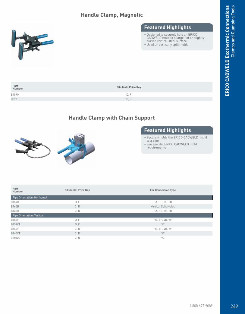
www.erico.pentair.com 1.800.677.9089 249
ERIC
O C
ADW
ELD
Exo
ther
mic
Con
nect
ions
Clam
ps a
nd C
lam
ping
Too
ls
Handle Clamp, Magnetic
• Designed to securely hold an ERICO CADWELD mold to a large flat or slightly curved vertical steel surface
• Used on vertically split molds
Featured Highlights
Part Number Fits Mold Price Key
B159M D, FB396 C, R
Handle Clamp with Chain Support
• Securely holds the ERICO CADWELD mold to a pipe
• See specific ERICO CADWELD mold requirements
Featured Highlights
Part Number Fits Mold Price Key For Connection Type
Pipe Orientation: HorizontalB159H D, F HA, HC, HS, HTB160B C, R Vertical Split MoldsB160H C, R HA, HC, HS, HT
Pipe Orientation: VerticalB159V D, F VS, VF, VB, VVB159VT D, F VTB160V C, R VS, VF, VB, VVB160VT C, R VTL160VG C, R VG

www.erico.pentair.com250
ERICO
CADW
ELD Exotherm
ic ConnectionsClam
ps and Clamping Tools
Handle Clamp Chain
• Handle clamp accessory used on specific clamps to securely hold the ERICO CADWELD mold to a pipe
• See specific ERICO CADWELD mold requirements
Featured Highlights
Part Number For Connection Type Handle Clamp Chain Length Pipe Orientation Pipe Size
B158 HA, HC, HS, HT, VB B159V, B160V, B159VT, B160VT, B159H, and B160H 20” Horizontal, Vertical 4” – 10”
Magnetic Assembly
• Powerful welding magnet securely positions the mold during the connection process to a flat steel surface or steel pipe
• Helps with mold stability to reduce the chance of welding material leakage
• Quickly and easily attaches to hold down “A” Price Key molds (new or retrofit)
• Assembly is adjustable• Ideal when used with ERICO CADWELD
PLUS to allow for use of full extension of control unit lead
Featured Highlights
Part Number
B323N2

www.erico.pentair.com 1.800.677.9089 251
ERIC
O C
ADW
ELD
Exo
ther
mic
Con
nect
ions
Clam
ps a
nd C
lam
ping
Too
ls
Pipe Clamp Chain
• Handle clamp accessory• Used on specific clamps to hold the ERICO
CADWELD mold to a particular surface• See specific ERICO CADWELD mold
requirements
Featured Highlights
Part Number Fits Mold Price Key Pipe Size Pipe Orientation
B319 CAN, CAP, CAT 6” Max VerticalB320 CAA 6” Max Horizontal
Support Clamp for Vertical Flat Steel Surface
• Securely supports an ERICO CADWELD mold to a vertical “H” column or angle
• Easily attaches to an L160 or L159 handle clamp
• For use with type VF molds for up to 3/4” (19.1 mm) thick steel
• For use with type VB, VG, VN, and VS molds for up to 1” (25.4 mm) thick steel
Featured Highlights
Part Number For Use With Handle Clamp
B134 L160, Sold SeparatelyB135 L159, Sold Separately
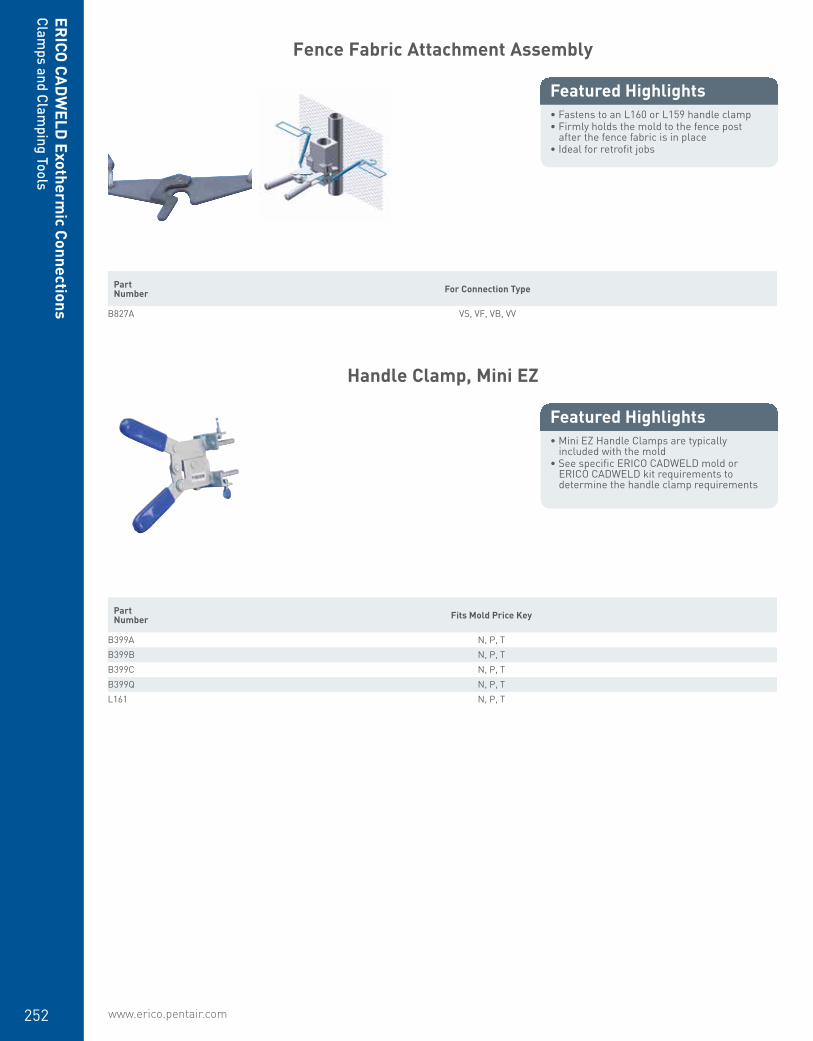
www.erico.pentair.com252
ERICO
CADW
ELD Exotherm
ic ConnectionsClam
ps and Clamping Tools
Fence Fabric Attachment Assembly
• Fastens to an L160 or L159 handle clamp• Firmly holds the mold to the fence post
after the fence fabric is in place• Ideal for retrofit jobs
Featured Highlights
Part Number For Connection Type
B827A VS, VF, VB, VV
Handle Clamp, Mini EZ
• Mini EZ Handle Clamps are typically included with the mold
• See specific ERICO CADWELD mold or ERICO CADWELD kit requirements to determine the handle clamp requirements
Featured Highlights
Part Number Fits Mold Price Key
B399A N, P, TB399B N, P, TB399C N, P, TB399Q N, P, TL161 N, P, T
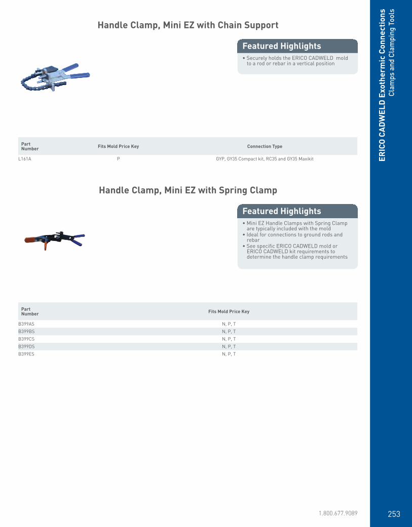
www.erico.pentair.com 1.800.677.9089 253
ERIC
O C
ADW
ELD
Exo
ther
mic
Con
nect
ions
Cla
mps
and
Cla
mpi
ng T
ools
Handle Clamp, Mini EZ with Chain Support
• Securely holds the ERICO CADWELD mold to a rod or rebar in a vertical position
Featured Highlights
Part Number Fits Mold Price Key Connection Type
L161A P GYP, GY35 Compact kit, RC35 and GY35 Maxikit
Handle Clamp, Mini EZ with Spring Clamp
• Mini EZ Handle Clamps with Spring Clamp are typically included with the mold
• Ideal for connections to ground rods and rebar
• See specific ERICO CADWELD mold or ERICO CADWELD kit requirements to determine the handle clamp requirements
Featured Highlights
Part Number Fits Mold Price Key
B399AS N, P, TB399BS N, P, TB399CS N, P, TB399DS N, P, TB399ES N, P, T

www.erico.pentair.com254
ERICO
CADW
ELD Exotherm
ic ConnectionsClam
ps and Clamping Tools
Handle Clamp, Mini EZ, Magnetic
• Designed to securely hold an ERICO CADWELD mold to a large flat or slightly curved vertical steel surface
• Allows for simple placement of the ERICO CADWELD mold in the desired connection location
• See specific ERICO CADWELD mold or ERICO CADWELD kit requirements to determine the handle clamp requirements
Featured Highlights
Part Number Fits Mold Price Key
B399AM N, P, TB399BM N, P, T
Cable Clamp Assembly
• Designed for use with hard-drawn copper cable, copper-bonded conductors or any cable under tension
• Use of the clamp aids in preventing cable movement and prolongs mold life
Featured Highlights
Part Number
B265

www.erico.pentair.com 1.800.677.9089 255
ERIC
O C
ADW
ELD
Exo
ther
mic
Con
nect
ions
Disk
s, S
leev
es, S
him
s an
d Ba
ttin
g
Ground Rod Clamping Tool
• Must be used to provide the correct positioning of ground rods and mold while splicing the rods with ERICO CADWELD for HDGB and GB type connections
Featured Highlights
Part Number
B120
Disk
• Required each time a traditional ERICO CADWELD connection is made
• Placed at the bottom of the crucible, holding the welding material until the reaction takes place
Featured Highlights
Material: Steel Part Number Welding Material Diameter
B117A 15 - 32, Sold Separately 3/4”B117B 45 - 115, Sold Separately 1”B117C 150 - 500, Sold Separately 1 1/2”

www.erico.pentair.com256
ERICO
CADW
ELD Exotherm
ic ConnectionsDisks, Sleeves, Shim
s and Batting
Disk Kit
• Contains three disk sizes for common ERICO CADWELD connection applications
• Convenience item for replacing lost or damaged disks
Featured Highlights
Part Number Material
T328D Steel
Disk Container
• Metal container for holding disks and small ERICO CADWELD accessories
Featured Highlights
Part Number Diameter Height
T328 3” 1”

www.erico.pentair.com 1.800.677.9089 257
ERIC
O C
ADW
ELD
Exo
ther
mic
Con
nect
ions
Disk
s, S
leev
es, S
him
s an
d Ba
ttin
g
Conductor Sleeve
• Used to adapt a limited range of smaller size cables to a larger size ERICO CADWELD Mold
• Provides strength and stability on finely-stranded copper conductors
Featured Highlights
L
Ø
T
Part Number Length Thickness Diameter
Material: Copper — Finish: TinnedType — Chamfered:S01 1.000” 0.031” 0.561”S07 1.000” 0.031” 0.671”SBS09C 1.000” 0.031” 0.328”SBS11C 0.813” 0.031” 0.212”SBS12C 1.063” 0.031” 0.212”SBS13C 1.500” 0.031” 0.212”
Material: Copper — Finish: TinnedType — Flared:180380 0.984” 0.094” 0.209”H102F 1.024” 0.041” 0.169”H106AF 1.378” 0.039” 0.591”H106F 1.024” 0.039” 0.591”H113F 1.024” 0.039” 0.315”H11F 1.024” 0.039” 0.512”PBS24F 1.500” 0.031” 0.795”S01F 1.000” 0.031” 0.561”S02F 1.000” 0.031” 0.611”S03F 1.000” 0.031” 0.455”S05F 1.000” 0.031” 0.391”S06F 1.000” 0.031” 0.480”S07F 1.000” 0.031” 0.671”S09F 1.000” 0.031” 0.328”S17F 1.000” 0.031” 0.344”S20F 1.000” 0.031” 0.240”S429F1C12 0.750” 0.015” 0.134”S429F1F 0.375” 0.015” 0.168”S429F1J 0.375” 0.015” 0.212”S429F1N 0.438” 0.015” 0.268”S429F1N12 0.750” 0.015” 0.268”S429F1S 0.438” 0.015” 0.300”S429F1W 0.438” 0.015” 0.336”S429F1W12 0.750” 0.015” 0.336”S429F2A 0.500” 0.015” 0.380”S429F2A12 0.750” 0.015” 0.380”S429F2E 0.500” 0.015” 0.428”S429F2E16 1.000” 0.015” 0.428”S429F2J 0.500” 0.020” 0.480”S429F2J16 1.000” 0.020” 0.480”S429F2N 0.563” 0.020” 0.540”S429F2N16 1.000” 0.020” 0.540”S429F2S 0.563” 0.020” 0.605”S429F2S16 1.000” 0.020” 0.605”S429F2W16 1.000” 0.020” 0.658”S429F3B16 1.000” 0.020” 0.722”S429F3F 0.688” 0.020” 0.780”
www.erico.pentair.com258
ERICO
CADW
ELD Exotherm
ic ConnectionsDisks, Sleeves, Shim
s and Batting
Part Number Length Thickness Diameter
S429F3F16 1.000” 0.020” 0.780”S429F3K16 1.000” 0.025” 0.832”S429F3M12 0.750” 0.015” 0.242”S429F3N16 1.000” 0.025” 0.882”S429F3S20 1.250” 0.025” 0.930”S429F4C16 1.000” 0.020” 0.466”S429F4K16 1.000” 0.020” 0.666”S429F4M16 1.000” 0.020” 0.749”S429F4N24 1.500” 0.035” 1.155”S429F4P16 1.000” 0.020” 0.799”S429F4T20 1.250” 0.025” 0.982”S429F4X24 1.500” 0.035” 1.074”S429F5A24 1.500” 0.035” 1.332”S429F5B24 1.500” 0.035” 1.134”S429F5E24 1.500” 0.035” 1.224”S429F5F24 1.500” 0.035” 1.375”S429FY922 1.375” 0.078” 0.833”
Material: Copper — Finish: TinnedType — Straight:B112 1.063” 0.031” 0.212”B1331H 1.000” 0.025” 0.106”B1331K 1.000” 0.031” 0.140”B1331L 1.000” 0.031” 0.170”B1331V 1.000” 0.031” 0.240”B1331Y 1.000” 0.031” 0.265”B1332C 1.000” 0.031” 0.312”B1332G 1.000” 0.031” 0.344”B1332L 1.000” 0.031” 0.391”B1332Q 1.000” 0.031” 0.430”H101 1.024” 0.039” 0.236”H102 0.984” 0.041” 0.169”H103 0.984” 0.047” 0.209”H105 0.925” 0.039” 0.118”H117 0.984” 0.039” 0.276”S4291F 0.375” 0.015” 0.168”S4291J 0.375” 0.015” 0.212”S4291N12 0.750” 0.015” 0.268”S4291W 0.438” 0.015” 0.336”S4291W12 0.750” 0.015” 0.336”S4292A 0.500” 0.015” 0.380”S4292E 0.500” 0.015” 0.428”S4292J 0.500” 0.020” 0.480”S4292J16 1.000” 0.020” 0.480”S4292N 0.563” 0.020” 0.540”S4292S 0.563” 0.020” 0.605”S4293F 0.688” 0.020” 0.780”
Material: Steel — Finish: Copper PlatedType — Flared:KH118003532 2.000” 0.035” 1.180”

www.erico.pentair.com 1.800.677.9089 259
ERIC
O C
ADW
ELD
Exo
ther
mic
Con
nect
ions
Disk
s, S
leev
es, S
him
s an
d Ba
ttin
g
Sleeve Kit
• Contains a variety of adapter sleeves that allow a buildup of smaller conductors to fit the opening of larger sized conductors in a ERICO CADWELD mold
• Includes shim stock for wrapping around a conductor, increasing the diameter to fit larger conductor openings in a ERICO CADWELD mold
• Contains extra disks for all sizes of traditional welding material
• Includes extra flints for ERICO CADWELD Flint Ignitors
Featured Highlights
Part Number
T427
Copper Shim
• Wrapped around the cable until the diameter is about the same as the cable opening in the mold
Featured Highlights
L
W
Material: Copper Part Number Length Width Thickness
B140A 1.5” 3.0” 0.013”B140B 2.5” 3.0” 0.013”B140K 4.5” 1.5” 0.013”B140L 5.5” 1.5” 0.013”B140N 3.0” 1.5” 0.013”B141A 1.5” 3.0” 0.013”B141C 2.5” 3.0” 0.013”

www.erico.pentair.com260
ERICO
CADW
ELD Exotherm
ic ConnectionsDisks, Sleeves, Shim
s and Batting
ERICO CADWELD Replacement Part Kit
• Miscellaneous handle clamp and ERICO CADWELD connection accessories
• Kit includes: (1) disk container, (2) handle clamp thumb screws, (1) handle clamp clevis pin, (1) handle clamp hitch pin, (1) handle clamp adjustment screw, (10) replacement flints, (4) B140A copper shims, (5) B1331L tinned copper sleeves, and (5) B1332Q tinned copper sleeves
Featured Highlights
Part Number
K158A
Batting/Packing Material
• Preformed ceramic packing material• Seals mold conductor openings• Prevents welding material leakage• See ERICO CADWELD mold requirements
for specific batting part number
Featured Highlights
Part Number
ACB4000H1ACC4005H2ACC4007H3ACC4035H8ACC4035H9ACC4061H1ACC4061H2ACC4061H3ACC4061H4ACC4062H1B142AB142BB143AB143BB144AB144BB144CB144DB144EB144MB144QB145A

www.erico.pentair.com 1.800.677.9089 261
ERIC
O C
ADW
ELD
Exo
ther
mic
Con
nect
ions
Tool
s an
d Ac
cess
orie
s
Galvanizing Bar
• Used to repair a galvanized surface that has been damaged by welding or drilling
• Low-temperature self-fluxing material• The bar may be melted using the heat
produced after making a ERICO CADWELD connection, or a small torch may be used
Featured Highlights
Part Number Material
T319 Zinc Alloy
Galvanizing Spray
• Easy-to-use galvanizing paint in a spray can• Used to touch up heat affected areas on
galvanized steel surfaces after welding
Featured Highlights
Part Number Unit Weight
T372A 1 lb
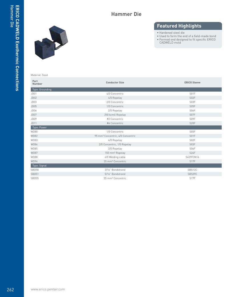
www.erico.pentair.com262
ERICO
CADW
ELD Exotherm
ic ConnectionsH
amm
er Die
Hammer Die
• Hardened steel die• Used to form the end of a field-made bond• Formed end designed to fit specific ERICO
CADWELD mold
Featured Highlights
Material: Steel Part Number Conductor Size ERICO Sleeve
Type: GroundingJD01 4/0 Concentric S01FJD02 4/0 Ropelay S02FJD03 2/0 Concentric S03FJD05 1/0 Concentric S05FJD06 2/0 Ropelay S06FJD07 250 kcmil Ropelay S07FJD09 #2 Concentric S09FJD11 #4 Concentric S20F
Type: PowerWD80 1/0 Concentric S05FWD82 95 mm² Concentric, 4/0 Concentric S01FWD83 4/0 Ropelay S02FWD84 2/0 Concentric, 1/0 Ropelay S03FWD85 2/0 Ropelay S06FWD87 150 mm² Ropelay S24FWD88 4/0 Welding cable S429F3N16WD94 35 mm² Concentric S17F
Type: SignalSBD50 3/16” Bondstrand SBS12CSBD51 5/16” Bondstrand SBS09CSBD55 35 mm² Concentric S17F

www.erico.pentair.com 1.800.677.9089 263
ERIC
O C
ADW
ELD
Exo
ther
mic
Con
nect
ions
Igni
tion
Syst
ems
Mold Sealer
• Ideal for sealing hot or cold molds to retard leakage from large stranded conductors
• Prolongs useful mold life when the cable opening becomes worn
• Required on certain ERICO CADWELD molds such as Types HA, HB, HC, VG and VN
Featured Highlights
Part Number Unit Weight
T403 2 lb
Flint Ignitor
• Used to ignite the starting material when making a traditional ERICO CADWELD connection or a LENTON CADWELD rebar connection
Featured Highlights
Part Number
T320

www.erico.pentair.com264
ERICO
CADW
ELD Exotherm
ic ConnectionsIgnition System
s
Replacement Flint
• Replacement flints for T320 Flint Ignitor
Featured Highlights
Part Number Standard Packaging Quantity
T320A 10 pc
Flint Ignitor Extension
• Attaches to T320 Flint Ignitor and allows the installer to be approximately 30” (762 mm) away from the mold
• Ideal for applications such as making a mold in a narrow trench while the installer is at ground level
Featured Highlights
Part Number
B32130

www.erico.pentair.com 1.800.677.9089 265
ERIC
O C
ADW
ELD
Exo
ther
mic
Con
nect
ions
Igni
tion
Syst
ems
ERICO CADWELD PLUS Control Unit
• Battery-powered controller box designed for 600 connections with one set of batteries
• Requires no special batteries or charger• Comes standard with high temperature lead• Connects to the welding material ignition
strip with a custom made, purpose-designed termination clip
• Sends a predetermined voltage to the ignition strip and initiates the reaction
• PBPLUSCU meets AREMA® C&S Manual Recommendations; Part 8.1.34, 2013
Featured Highlights
Part Number Cable Length Batteries Working Temperature Certifications
Type: Controller Box with LeadsPBPLUSCU 6’ 8 Lithium AA Batteries -40 to 140 °F cURusPLUSCU 6’ 8 Standard AA Batteries 0 – 130 °F cURus, NOMPLUSCU15L 15’ 8 Standard AA Batteries 0 – 130 °F cURus
Type: Replacement Leads OnlyPLUSCULD15QC 15’PLUSCULDQC 6’
Battery Pack
• Battery, charger, and carrying case required for the ignition of ERICO CADWELD EXOLON welding material
• Battery operates approximately 200 connections before requiring a recharge
• Charger, all electrical connections and instructions are included in the battery case
Featured Highlights
Part Number
XLB971A1
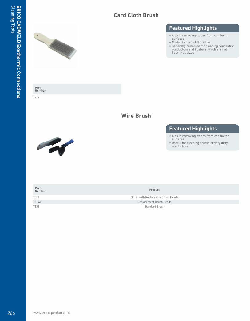
www.erico.pentair.com266
ERICO
CADW
ELD Exotherm
ic ConnectionsCleaning Tools
Card Cloth Brush
• Aids in removing oxides from conductor surfaces
• Made of short, stiff bristles• Generally preferred for cleaning concentric
conductors and busbars which are not heavily oxidized
Featured Highlights
Part Number
T313
Wire Brush
• Aids in removing oxides from conductor surfaces
• Useful for cleaning coarse or very dirty conductors
Featured Highlights
Part Number Product
T314 Brush with Replaceable Brush HeadsT314A Replacement Brush HeadsT336 Standard Brush

www.erico.pentair.com 1.800.677.9089 267
ERIC
O C
ADW
ELD
Exo
ther
mic
Con
nect
ions
Clea
ning
Too
ls
Mold Cleaning Brush
• Ideal for cleaning ERICO CADWELD molds• Soft bristles minimize wear of graphite
during the cleaning process• Removes slag and particles from mold
cavity, tap hole, crucible and cover
Featured Highlights
Part Number Type
T302A WideT394 Narrow
Mold Cleaner
• Used to remove the slag from the crucible area of the mold after making a ERICO CADWELD connection
Featured Highlights
Part Number Mold Type
B136A Most ERICO CADWELD molds using #65 welding material and smallerB136B Most ERICO CADWELD molds using #90 welding material and largerB136D Most ERICO CADWELD rail bond moldsB136E Specific ERICO CADWELD molds only (See mold requirements to determine need)B136F Specific ERICO CADWELD molds only (See mold requirements to determine need)

www.erico.pentair.com268
ERICO
CADW
ELD Exotherm
ic ConnectionsH
and Tools
ERICO CADWELD Tool Kit
• Convenient tool kits for ERICO CADWELD connection installations
Featured Highlights
Part Number Product
T315 Standard KitT315A Complete KitT343 Heavy-Duty KitT343R Heavy-Duty Kit with Rasp
Torch Head
• Self-igniting propane torch head• Squeezing the control knob produces an
instant flame; releasing it extinguishes the flame
• No flame adjusting • Burn tip remains cool during normal use• Operates on its side or upside down• Can withstand 60 MPH (96 KPH) winds
without flareout• Fits all standard 14.1 and 16.4 ounce (400
and 465 gram) propane cylinders
Featured Highlights
Part Number
T111
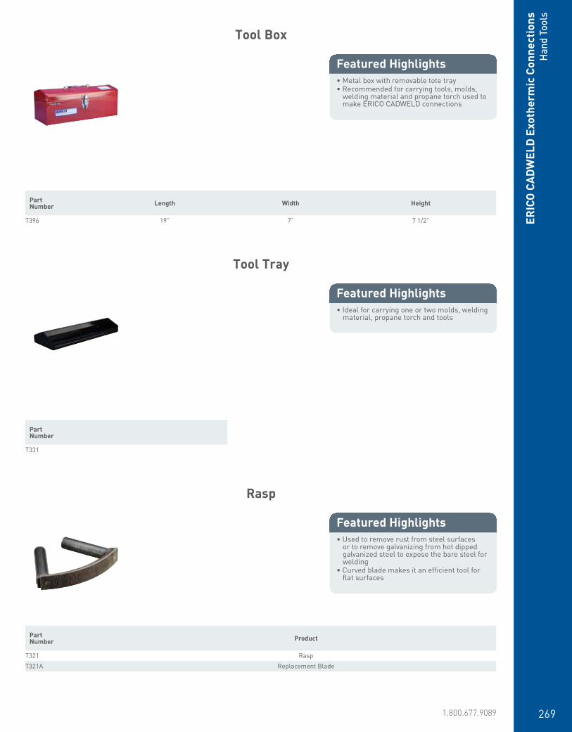
www.erico.pentair.com 1.800.677.9089 269
ERIC
O C
ADW
ELD
Exo
ther
mic
Con
nect
ions
Han
d To
ols
Tool Box
• Metal box with removable tote tray• Recommended for carrying tools, molds,
welding material and propane torch used to make ERICO CADWELD connections
Featured Highlights
Part Number Length Width Height
T396 19” 7” 7 1/2”
Tool Tray
• Ideal for carrying one or two molds, welding material, propane torch and tools
Featured Highlights
Part Number
T331
Rasp
• Used to remove rust from steel surfaces or to remove galvanizing from hot dipped galvanized steel to expose the bare steel for welding
• Curved blade makes it an efficient tool for flat surfaces
Featured Highlights
Part Number Product
T321 RaspT321A Replacement Blade
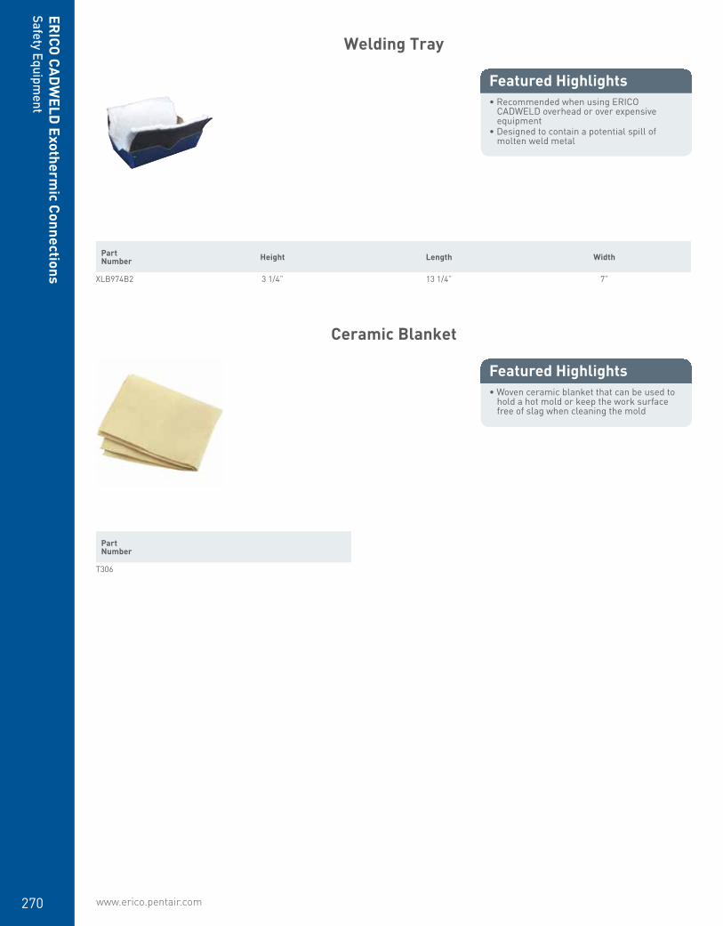
www.erico.pentair.com270
ERICO
CADW
ELD Exotherm
ic ConnectionsSafety Equipm
ent
Welding Tray
• Recommended when using ERICO CADWELD overhead or over expensive equipment
• Designed to contain a potential spill of molten weld metal
Featured Highlights
Part Number Height Length Width
XLB974B2 3 1/4” 13 1/4” 7”
Ceramic Blanket
• Woven ceramic blanket that can be used to hold a hot mold or keep the work surface free of slag when cleaning the mold
Featured Highlights
Part Number
T306
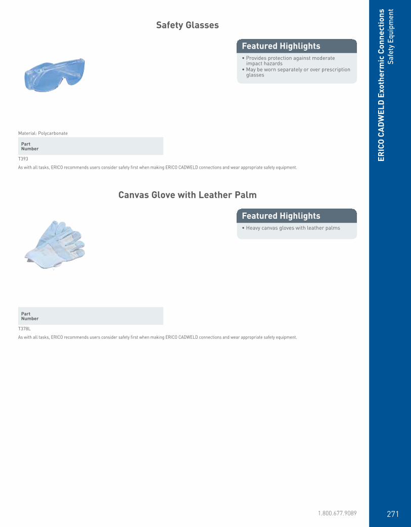
www.erico.pentair.com 1.800.677.9089 271
ERIC
O C
ADW
ELD
Exo
ther
mic
Con
nect
ions
Safe
ty E
quip
men
t
Safety Glasses
• Provides protection against moderate impact hazards
• May be worn separately or over prescription glasses
Featured Highlights
Material: Polycarbonate Part Number
T393
As with all tasks, ERICO recommends users consider safety first when making ERICO CADWELD connections and wear appropriate safety equipment.
Canvas Glove with Leather Palm
• Heavy canvas gloves with leather palms
Featured Highlights
Part Number
T378L
As with all tasks, ERICO recommends users consider safety first when making ERICO CADWELD connections and wear appropriate safety equipment.

www.erico.pentair.com272
www.erico.pentair.com 1.800.677.9089
TECHNICAL CHARTS
273

274 www.erico.pentair.com
Technical Charts
Size (AWG/MCM/mm2) Circular Mils Stranding Nominal O.D.
of StrandApprox, O.D.
(inches)Approx, O.D.
(mm)Weight
(lbs/mft)CADWELD Cable Code
8 AWG 16,510 Solid – 0.1285 3.26 50.0 1D8 AWG 16,510 7/.0486” 0.0486 0.1460 3.71 50.1 1E6 AWG 26,240 Solid – 0.1620 4.11 79.5 1G6 AWG 26,240 7/.0612” 0.0612 0.1840 4.67 81.1 1H16 mm2 31,600 7/1.17 0.0461 0.2010 5.11 96.1 W34 AWG 41.740 Solid – 0.2043 5.19 126.3 1K4 AWG 41,740 7/.0772” 0.0772 0.2320 5.89 129.0 1L4 AWG 41,740 19/.0469” 0.0469 0.2350 5.97 129.0 1L
25 mm2 49,300 7/2.14 mm 0.0843 0.2530 6.43 152.5 Y125 mm2 49,300 19/1.35 0.0531 0.2660 6.76 152.5 Y12 AWG 66,360 Solid – 0.2576 6.54 200.9 1T2 AWG 66,360 7/.0974” 0.0974 0.2920 7.42 204.9 1V2 AWG 66,360 19/.0591” 0.0591 0.2920 7.42 205.0 1V
35 mm2 66,360 19/1.53 mm 0.0602 0.3010 7.65 211.0 Y250 mm2 98,500 19/1.78 mm 0.0701 0.3500 8.89 287.6 Y31/0 AWG 105,600 Solid – 0.3249 8.25 319.5 2B1/0 AWG 105,600 7/.1228” 0.1228 0.3690 9.37 326.0 2C1/0 AWG 105,600 19/.0745” 0.0745 0.3730 9.47 326.0 2C2/0 AWG 133,100 Solid – 0.3648 9.27 402.8 2F2/0 AWG 133,100 7/.1379” 0.1379 0.4140 10.52 410.9 2G2/0 AWG 133,100 19/.0837” 0.0837 0.4190 10.64 410.9 2G70 mm2 138,000 19/2.14 mm 0.0843 0.4210 10.69 415.3 Y43/0 AWG 167,800 Solid – 0.4096 10.40 507.8 2K3/0 AWG 167,800 7/.1548” 0.1548 0.4650 11.81 518.0 2L3/0 AWG 167,800 19/.0940” 0.0940 0.4700 11.94 518.0 2L95 mm2 187,000 37/1.78 mm 0.0700 0.4910 12.47 576.5 Y595 mm2 187,000 19/2.52 0.0992 0.4960 12.60 576.5 Y54/0 AWG 211,600 Solid – 0.4600 11.68 610.5 2P4/0 AWG 211,600 7/.1739” 0.1739 0.5220 13.26 653.0 2Q4/0 AWG 211,600 19/.1055” 0.1055 0.5280 13.41 653.0 2Q120 mm2 237,000 37/2.03 mm 0.0799 0.5600 14.22 737.1 Y6250 MCM 250,000 19/.1147” 0.1147 0.5750 14.61 771.0 2V250 MCM 250,000 37/.0822” 0.0822 0.5750 14.61 771.0 2V150 mm2 296,000 37/2.25 mm 0.0886 0.6200 15.75 896.4 Y7300 MCM 300,000 19/.1257” 0.1257 0.6290 15.98 926.9 3A300 MCM 300,000 37/.0900” 0.0900 0.6290 15.98 926.9 3A185 mm2 365,000 27/2.52 mm 0.0992 0.6950 17.65 1124.1 Y8400 MCM 400,000 37/.1040 0.1040 0.7200 18.29 1235.2 3H240 mm2 474,000 61/2.25 mm 0.0886 0.7970 20.24 1478.2 Y9500 MCM 500,000 19/.1622” 0.1622 0.8130 20.65 1544.0 3Q500 MCM 500,000 37/.1162” 0.1162 0.8130 20.65 1544.0 3Q750 MCM 750,000 61/.1109” 0.1109 0.9980 25.35 2316.0 4L500 mm2 987,000 61/3.20 mm 0.1260 1.1340 28.80 2990.8 W1
1000 MCM 1,000,000 61/.1280” 0.1280 1.1520 29.26 3088.0 4Y
Concentric Stranded Conductor Sizes

275www.erico.pentair.com 1.800.677.9089
Technical Charts
Cable Stranding
Nominal Diameter kcmil Equivalent
Copper Size*CADWELD Cable Code
7/#10 .306 72.7 3 AWG 9A7/#8 .385 115.6 1 9B7/#7 .433 145.7 1/0 9C7/#6 .486 183.8 2/0 9D7/#5 .546 231.7 3/0 9E
19/#9 .572 248.8 3/0 9F7/#4 .613 292.2 4/0 9L
19/#8 .642 313.7 4/0 9G19/#7 .721 395.5 250 Kcmil 9H37/#9 .801 484.4 300 7W19/#6 .810 498.8 350 9J37/#8 .899 610.9 400 7V19/#5 .910 628.9 450 9K37/#7 1.010 770.3 500 9M
Nominal Size Material Type Thread
SizeBody Dia.
CADWELD Ground Rod
Code
1/2”
Copper-bonded Sectional
9/16”.505 14
Steel* Plain .500 14Copper-bonded Plain .475 15Copper-bonded Sectional 1/2” .447 13Copper-bonded Sectional
5/8”.563 16
5/8”
Steel* Plain .625 31Copper-bonded Plain .563 16Copper-bonded Sectional
3/4”.682 18
3/4”
Steel* Plain .750 33Copper-bonded Plain .682 18Copper-bonded Sectional
1”.914 22
1”Steel* Plain 1.000 37
Copper-bonded Plain .914 22
Thickness (inches)
Width (inches)
Circular Mil Size
Weight (lbs per foot)
CADWELD Busbar Code
1 159,200 .484 CE
1/81-1/2 238,700 .726 CG
2 318,300 .969 CH
3/16
1 238,700 .727 DE2 477,500 1.45 DH1 318,300 .969 EE
1-1/2 477,500 1.45 EG
1/4
2 636,600 1.94 EH3 954,900 2.91 EK4 1,273,000 3.88 EM1 477,500 1.45 GE
1-1/2 716,200 2.18 GG
3/8
2 954,900 2.91 GH3 1,432,000 4.36 GK4 1,910,000 5.81 GM2 1,273,000 3.88 JH
1/23 1,910,000 5.81 JK4 2,546,000 7.75 JM
Useful Conversions
Area Square Inches x 1273 = kcmil Square Millimeters x 1.974 = kcmil kcmil x 0.5067 = Square Millimeters
Density
Copper: 0.323 lb/in3 Steel: 0.283 lb/in3
Rebar Sizes
Nominal DimensionsEquivalent
Copper Sizes*
CADWELD Rebar CodeDia. (inches)
Cross-Secitonal Area (Sq.
inches)3 .375 .11 9 AWG 514 .500 .20 7 525 .625 .31 5 536 .750 .44 3 547 .875 .60 2 558 1.000 .79 1 569 1.128 1.00 1/0 57
10 1.270 1.27 2/0 5811 1.410 1.56 3/0 5914 1.693 2.25 250 kcmil 6018 2.257 4.00 450 61
DSA Copper-bonded Conductor
Reinforcing Bars
Bare Copper-Bonded Conductor
Rectangular Copper Busbar
*Approximate based on fusing current calculations
*Plain steel, stainless steel, stainless clad rods or galvanized steel.
* Based on 8% IACS, rounded to the next higher commercial copper size.

276 www.erico.pentair.com
Nominal Size (inches)
O.D.(inches) OD (mm) Wall Thickness
(inches)CADWELD Mold Code
1 1.315 33.4 .133 11-1/4 1.660 42.1 .140 1.251-1/2 1.900 48.2 .145 1.50
2 2.375 60.3 .154 22-1/2 2.875 73.0 .203 2.50
3 3.500 88.9 .216 33-1/2 4.000 101.6 .226 3.50
4 4.500 114.3 .237 45 5.563 141.3 .258 56 6.625 168.2 .280 68 8.625 219.0 .322 8
10 10.750 273.0 .365 10
Steel Pipe Sizes
Other Standard Sections used for Fence Posts
Standard Weight(Schedule 40)
ASTM® A53-90-BANSI®/ASME® B36.10M-1985
Section CADWELD Mold Code
1-1/2” square PS15 2” square PS20 2-1/2” square PS25 3” square PS30* 1.875 x 1.625 x .133 “H” PH1 2.25 x 1.95 .143 “H” PH2
*For D or F mold price only.
Technical Charts

277www.erico.pentair.com 1.800.677.9089
Index
15 236
15PLUSF20 236
25 236
25PLUSF20 236
32 236
32PLUSF20 237
45 236
45PLUSF20 237
65 236
65PLUSF20 237
90 236
90PLUSF20 237
115 236
115PLUSF20 236
150 236
150PLUSF20 236
200 236
200PLUSF20 236
250 236
250PLUSF20 236
300PLUSF20 237
400PLUSF20 237
500 236
500PLUSF20 237
600PLUSF20 237
750PLUSF20 237
1250PLUSF20 236
50010EBOSS 72
158100 163
158110 163
158380 162
180380 255
545135 125
545140 125
545530 125
611300 114
611300UPC 114
611303 114
611330 114
611340 114
611350 114
611353 114
611360 114
611360UPC 114
611380 114
611380UPC 114
613400 114
613400UPC 114
613403 114
613412 114
613415 114
613440 114
613450 114
613460 114
613480 114
613483 114
613840 114
613840UPC 114
613850 114
613860 114
613880 114
614400 114
615800 114
615800UPC 114
615803 114
615812 114
615815 114
615823 114
615830 114
615840 114
615840UPC 114
615843 115
615850 115
615853 115
615860 115
615860UPC 115
615863 115
615880 115
615880UPC 115
615883 115
615883UPC 115
625850 115
631300 115
631303 115
631340 115
631350 115
631360 115
631380 115
633400 115
633403 115
633415 115
633430 115
633440 115
633450 115
633460 115
633463 115
633470 115
633480 115
634400 116
635800 116
635803 116
635830 116
635837 117
635840 116
635843 116
635850 116
635860 116
635870 116
635880 116
635883 116
663400 141
681300 117
681300S 118
683400 117
683400S316 118
683412 117
683450 117
683450S 118
683480 117
684400 117
684400S 118
684415 117
685800 117
685800S 118
685880 117
685880S 118
685880UPC 117
710090 163
710100 163
811260UPC 121
811280UPC 121
811350 121
811360 121
811380 121
813400 121
813400UPC 121
813480 121
814400 121
815800 121
815800UPC 121
815840 121
815850 121
815860 121
815860UPC 121
815880 121
815880UPC 121
A235C2C1LH 89
A235D2G2RH 89
A235D2G4LH 89
A235D2Q4LH 89
A235D2Q4RH 89
A235D2Q5LH 89
A235D2Q5RH 89
A235E2G4LH 89
A235E2Q2RH 89
A235E2Q4LH 89
A235E2Q5LH 89
A235E2Q5RH 89
A235F2C2LH 89
A235G2Q2RH 89
A235H2C10RH 89
A238EB2S12LH 90
A238EC2S12LH 90
A238EC2S12RH 90
A238EC2S24LH 90
A238EC2S24RH 90
A238FC2S12LH 90
A238FC2S12RH 90
A238FC2S16LH 90
A238FC2S16RH 90
A238FC2S18LH 90
A238FC2S18RH 90
A238FC2S24LH 90
A238FC2S24RH 90
A238FD2S18LH 90
A238FD2S18RH 90
A238FF2S12RH 90
A238GC2S12LH 90
A238GC2S12RH 90
A238GC2S18LH 90
A238GC2S18RH 90
A238GC2S24LH 90
A238GC2S24RH 90
A238GD2S24RH 90
A238HB2S18LH 90
A238HB2S18RH 91
A238HC2S24LH 90
A238HD2S24RH 91
A238KC2S24LH 90
A238KC2S24RH 91
A238KD2S24RH 91
A239DC2S242C4LH 91
A239EB2S242Q4RH 92
A239EC2S182Q6LH 91
A239EC2S242C4LH 91
A239EC2S242C4RH 92
A239EC2S242G8LH 91
A239EC2S242Q4LH 91
A239EC2S242Q4RH 92
A239FC2S122G24R 92
A239FC2S242C2LH 91
A239FC2S242C2RH 92
A239FC2S242G4LH 91
A239FC2S242G4RH 92
A239FC2S242G5LH 91
A239FC2S242G5RH 92
A239FC2S242Q2LH 92
A239FC2S242Q4LH 92
A239FC2S242Q4RH 92
A239FC2S242Q8LH 92
A239FC2S242Q10L 91
A239FD2S241V1LH 92
A239FD2S242G4LH 92
A239FD2S242G4RH 92
A239GC2S242Q4LH 92
A239GC2S242Q4RH 92
A239HB2S242Q1RH 92
A239HC2S182C5LH 92
A239HC2S182C5RH 92
A239HC2S182Q6LH 92
A239HC2S242C4LH 92
A239HC2S242C4RH 92
A239HC2S242C10L 92
A239HC2S242C10R 92
A239HC2S242G4LH 92
A239HC2S242G5LH 92
A239HC2S242G5RH 92
A239HC2S242G30L 92
A239HC2S242G30R 92
A239HC2S242Q2LH 92
A239HC2S242Q2RH 92
A239HD2S242Q2LH 92
A239HD2S242Q2RH 92
A239HD2S242Q5LH 92
A239HD2S242Q5RH 92
A239KD2S242Q4RH 92
A800A09F65 107
A800A09F100 107
A800A22F100 107
A809A06F100 107
A811A26F50 110
A811A26F500 110
A811A26W4F500 110
A811C20F20 110
A811C20F100 110
ACB4000H1 258
ACC4005H2 258
ACC4007H3 258
ACC4035H8 258
ACC4035H9 258
ACC4061H1 258
ACC4061H2 258
ACC4061H3 258
ACC4061H4 258
ACC4062H1 258
B101AA 240
B101CE 240
B101CEOL 242
B101DE 240
B101DEOL 242
B101EE 240
B101EEOL 242
B101EG 240
B101EGOL 242
B101GG 240
B101GGOL 242
B101GH 240
B101GHOL 242
B101JH 240
B101QQ 240
Part Page Part Page Part Page Part Page Part Page
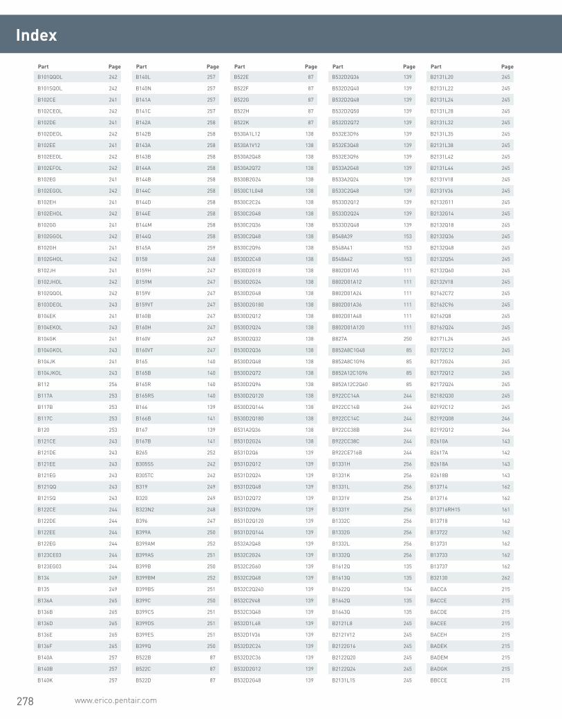
278 www.erico.pentair.com
B101QQOL 242
B101SQOL 242
B102CE 241
B102CEOL 242
B102DE 241
B102DEOL 242
B102EE 241
B102EEOL 242
B102EFOL 242
B102EG 241
B102EGOL 242
B102EH 241
B102EHOL 242
B102GG 241
B102GGOL 242
B102GH 241
B102GHOL 242
B102JH 241
B102JHOL 242
B102QQOL 242
B103DEOL 243
B104EK 241
B104EKOL 243
B104GK 241
B104GKOL 243
B104JK 241
B104JKOL 243
B112 256
B117A 253
B117B 253
B117C 253
B120 253
B121CE 243
B121DE 243
B121EE 243
B121EG 243
B121QQ 243
B121SQ 243
B122CE 244
B122DE 244
B122EE 244
B122EG 244
B123CE03 244
B123EG03 244
B134 249
B135 249
B136A 265
B136B 265
B136D 265
B136E 265
B136F 265
B140A 257
B140B 257
B140K 257
B140L 257
B140N 257
B141A 257
B141C 257
B142A 258
B142B 258
B143A 258
B143B 258
B144A 258
B144B 258
B144C 258
B144D 258
B144E 258
B144M 258
B144Q 258
B145A 259
B158 248
B159H 247
B159M 247
B159V 247
B159VT 247
B160B 247
B160H 247
B160V 247
B160VT 247
B165 140
B165B 140
B165R 140
B165RS 140
B166 139
B166B 141
B167 139
B167B 141
B265 252
B305SS 242
B305TC 242
B319 249
B320 249
B323N2 248
B396 247
B399A 250
B399AM 252
B399AS 251
B399B 250
B399BM 252
B399BS 251
B399C 250
B399CS 251
B399DS 251
B399ES 251
B399Q 250
B522B 87
B522C 87
B522D 87
B522E 87
B522F 87
B522G 87
B522H 87
B522K 87
B530A1L12 138
B530A1V12 138
B530A2Q48 138
B530A2Q72 138
B530B2G24 138
B530C1L048 138
B530C2C24 138
B530C2G48 138
B530C2Q36 138
B530C2Q48 138
B530C2Q96 138
B530D2C48 138
B530D2G18 138
B530D2G24 138
B530D2G48 138
B530D2G180 138
B530D2Q12 138
B530D2Q24 138
B530D2Q32 138
B530D2Q36 138
B530D2Q48 138
B530D2Q72 138
B530D2Q96 138
B530D2Q120 138
B530D2Q144 138
B530D2Q180 138
B531A2Q36 138
B531D2G24 138
B531D2Q6 139
B531D2Q12 139
B531D2Q24 139
B531D2Q48 139
B531D2Q72 139
B531D2Q96 139
B531D2Q120 139
B531D2Q144 139
B532A2Q48 139
B532C2G24 139
B532C2G60 139
B532C2Q48 139
B532C2Q240 139
B532C2V48 139
B532C3Q48 139
B532D1L48 139
B532D1V36 139
B532D2C24 139
B532D2C36 139
B532D2G12 139
B532D2G48 139
B532D2Q36 139
B532D2Q40 139
B532D2Q48 139
B532D2Q50 139
B532D2Q72 139
B532E3D96 139
B532E3Q48 139
B532E3Q96 139
B533A2G48 139
B533A2Q24 139
B533C2Q48 139
B533D2Q12 139
B533D2Q24 139
B533D2Q48 139
B548A39 153
B548A41 153
B548A42 153
B802D01A5 111
B802D01A12 111
B802D01A24 111
B802D01A36 111
B802D01A48 111
B802D01A120 111
B827A 250
B852A8C1G48 85
B852A8C1G96 85
B852A12C1G96 85
B852A12C2Q60 85
B922CC14A 244
B922CC14B 244
B922CC14C 244
B922CC38B 244
B922CC38C 244
B922CE716B 244
B1331H 256
B1331K 256
B1331L 256
B1331V 256
B1331Y 256
B1332C 256
B1332G 256
B1332L 256
B1332Q 256
B1612Q 135
B1613Q 135
B1622Q 134
B1642Q 135
B1643Q 135
B2121L8 245
B2121V12 245
B2122G16 245
B2122Q20 245
B2122Q24 245
B2131L15 245
B2131L20 245
B2131L22 245
B2131L24 245
B2131L28 245
B2131L32 245
B2131L35 245
B2131L38 245
B2131L42 245
B2131L44 245
B2131V18 245
B2131V36 245
B2132G11 245
B2132G14 245
B2132Q18 245
B2132Q36 245
B2132Q48 245
B2132Q54 245
B2132Q60 245
B2132V18 245
B2162C72 245
B2162C96 245
B2162Q8 245
B2162Q24 245
B2171L24 245
B2172C12 245
B2172G24 245
B2172Q12 245
B2172Q24 245
B2182Q30 245
B2192C12 245
B2192Q08 246
B2192Q12 246
B2610A 143
B2617A 142
B2618A 143
B2618B 143
B13714 162
B13716 162
B13716RH15 161
B13718 162
B13722 162
B13731 162
B13733 162
B13737 162
B32130 262
BACCA 215
BACCE 215
BACDE 215
BACEE 215
BACEH 215
BADEK 215
BADEM 215
BADGK 215
BBCCE 215
Index
Part Page Part Page Part Page Part Page Part Page
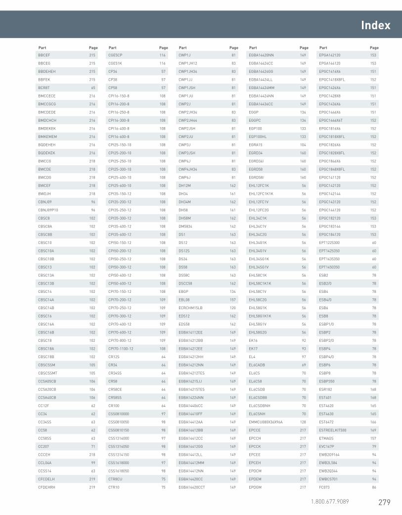
279www.erico.pentair.com 1.800.677.9089
Index
BBCEF 215
BBCEG 215
BBDEHEH 215
BBFEK 215
BCR8T 65
BMCCECE 216
BMCCGCG 216
BMCDEDE 216
BMDCHCH 216
BMDEKEK 216
BMKEMEM 216
BQDEHEH 216
BQDEKEK 216
BWCCG 218
BWCDE 218
BWCDG 218
BWCEF 218
BWDJH 218
CBNJ09 96
CBNJ09P10 96
CBSC8 102
CBSC8A 102
CBSC8B 102
CBSC10 102
CBSC10A 102
CBSC10B 102
CBSC13 102
CBSC13A 102
CBSC13B 102
CBSC14 102
CBSC14A 102
CBSC14B 102
CBSC16 102
CBSC16A 102
CBSC16B 102
CBSC18 102
CBSC18A 102
CBSC18B 102
CBSCSSM 105
CBSCSSMT 105
CC5A05CB 106
CC5A20CB 106
CC5A40CB 106
CC12F 62
CC34 62
CC34SS 63
CC58 62
CC58SS 63
CC207 71
CCCEH 218
CCL04A 99
CCSS14 63
CFCDELH 219
CFDEHRH 219
CGE5CP 116
CGE51K 116
CP34 57
CP38 57
CP58 57
CPI16-150-8 108
CPI16-200-8 108
CPI16-250-8 108
CPI16-300-8 108
CPI16-400-8 108
CPI16-600-8 108
CPI25-150-10 108
CPI25-200-10 108
CPI25-250-10 108
CPI25-300-10 108
CPI25-400-10 108
CPI25-600-10 108
CPI35-150-12 108
CPI35-200-12 108
CPI35-250-12 108
CPI35-300-12 108
CPI35-400-12 108
CPI35-600-12 108
CPI50-150-12 108
CPI50-200-12 108
CPI50-250-12 108
CPI50-300-12 108
CPI50-400-12 108
CPI50-600-12 108
CPI70-150-12 108
CPI70-200-12 109
CPI70-250-12 109
CPI70-300-12 109
CPI70-400-12 109
CPI70-600-12 109
CPI70-800-12 109
CPI70-1100-12 108
CR12S 64
CR34 64
CR34SS 64
CR58 64
CR58CE 64
CR58SS 64
CR100 64
CSS0810000 97
CSS0810050 98
CSS0810150 98
CSS1314000 97
CSS1314050 98
CSS1314150 98
CSS1618000 97
CSS1618050 98
CTR8CU 75
CTR10 75
CWP1J 81
CWP1JH12 83
CWP1JH34 83
CWP1JJ 81
CWP1JSH 81
CWP1JU 81
CWP2J 81
CWP2JH34 83
CWP2JH44 83
CWP2JSH 81
CWP2JU 81
CWP3J 81
CWP3JSH 81
CWP4J 81
CWP4JH34 83
CWP6J 81
DH12M 162
DH34 161
DH34M 162
DH58 161
DH58M 162
DM5834 142
DS1 163
DS12 163
DS12S 163
DS34 163
DS58 163
DS58C 163
DSCC58 162
EBGP 134
EBL08 157
ECRCHM15LB 120
EDS12 162
EDS58 162
EGBA14112EE 149
EGBA14212BB 149
EGBA14212EE 149
EGBA14212HH 149
EGBA14212NN 149
EGBA14212TES 149
EGBA14215JJ 149
EGBA14215TES 149
EGBA14224NN 149
EGBA14406CC 149
EGBA14410FF 149
EGBA14412AA 149
EGBA14412BB 149
EGBA14412CC 149
EGBA14412GG 149
EGBA14412LL 149
EGBA14412MM 149
EGBA14412NN 149
EGBA14420CC 149
EGBA14420CCT 149
EGBA14420NN 149
EGBA14424CC 149
EGBA14424GG 149
EGBA14424LL 149
EGBA14424MM 149
EGBA14424NN 149
EGBA14436CC 149
EGGP 134
EGGPC 134
EGP100 133
EGP100HL 133
EGRA15 104
EGRD34 160
EGRD34I 160
EGRD58 160
EGRD58I 160
EHL12FC1K 56
EHL12FC1K1K 56
EHL12FC1V 56
EHL12FC2G 56
EHL34C1K 56
EHL34C1V 56
EHL34C2G 56
EHL34G1K 56
EHL34G1V 56
EHL34SG1K 56
EHL34SG1V 56
EHL58C1K 56
EHL58C1K1K 56
EHL58C1V 56
EHL58C2G 56
EHL58G1K 56
EHL58G1K1K 56
EHL58G1V 56
EHL58G2G 56
EK16 92
EK17 93
EL4 97
EL6CADB 69
EL6CS 70
EL6CS8 70
EL6CSDB 70
EL6CSDB8 70
EL6CSDBNH 70
EL6CSNH 70
EMMCU080X36X96A 128
EPCCE 217
EPCCH 217
EPCCK 217
EPCEE 217
EPCEH 217
EPDCM 217
EPDEM 217
EPDGM 217
EPGA142120 153
EPGA144120 153
EPGC1416X6 151
EPGC1418X8FL 152
EPGC1426X6 151
EPGC1428X8 151
EPGC1436X6 151
EPGC1446X6 151
EPGC1446X6T 152
EPGC1816X6 152
EPGC1818X8FL 152
EPGC1826X6 152
EPGC1828X8FL 152
EPGC1846X6 152
EPGC1848X8FL 152
EPGC141120 152
EPGC142120 152
EPGC142144 152
EPGC143120 152
EPGC144120 152
EPGC182120 153
EPGC183144 153
EPGC184120 153
EPT1225300 60
EPT1425350 60
EPT1435350 60
EPT1450350 60
ESB2 78
ESB2/0 78
ESB4 78
ESB4/0 78
ESB6 78
ESB8 78
ESBP1/0 78
ESBP2 78
ESBP2/0 78
ESBP4 78
ESBP4/0 78
ESBP6 78
ESBP8 78
ESBP350 78
ESR182 168
EST401 168
EST4620 165
EST4630 165
EST6472 166
ESTREELKIT500 169
ETMAGS 157
EVC167P 79
EWB2G9164 94
EWB2L584 94
EWB2Q344 94
EWBCS701 94
FC073 86
Part Page Part Page Part Page Part Page Part Page

280 www.erico.pentair.com
Index
FC074 86
FC075 86
FC076 86
FC076DH 86
FC078 86
FC078DH 86
FC079 86
FC080 86
FC082 86
FC082DH 86
FJ1T18 87
FJ1T24 87
FJ1T42 87
FJ1T96 87
FJ1T240 87
FJ2G12 88
FJ2G16 88
FJ2G18 88
FJ2G24 88
FJ2G30 88
FJ2G36 88
FJ2G72 88
FJ2G84 88
FJ2G96 88
FJ2G120 88
FJ2G132 88
FJ2G144 88
FJ2G168 88
FJ2G180 88
FJ2G228 88
FJ2G360 88
FJ2Q16 88
FJ2Q18 88
FJ2Q24 88
FJ2Q36 88
FJ2Q48 88
FJ2Q120 88
FJ2Q156 88
FJ2Q168 88
FJ2Q180 88
FJ2Q216 88
FJ2Q240 88
FJ2Q252 88
FJ2Q384 88
FJ2Q600 88
FJ2QA24 88
GC064 58
GC065 58
GC065TH 59
GCC34 63
GCC58F 63
GEC14 183
GEC16 183
GEC18 183
GEC31 183
GEM25A 122
GEM25ABKT 122
GLCCE1G 209
GLCCE1H 209
GLCCE1K 209
GLCCE1L 209
GLCCE1T 209
GLCCE1V 209
GLCCE1Y 209
GLCCE2C 209
GLCCE2G 209
GLCCE2Q 209
GLCDE1H 209
GLCDE2C 209
GLCDE2G 209
GLCDE2Q 209
GLCDE2V 209
GLCEE2Q 209
GLCEE2V 209
GLCEE3A 209
GLCEE3D 209
GLCEG1V 209
GLCEG2C 209
GLCEG2G 209
GLCEG2Q 209
GLCEG2V 209
GLCEG3H 209
GLCEG3Q 209
GLPCC1T 209
GNR161H 194
GNR161T 194
GNR161V 194
GNR162C 194
GNR181H 194
GNR181T 194
GPECCAM036 131
GPECCAM0361H024 131
GPECCBJ0181T024 131
GPECCBJ0181T060 131
GPECCBJ181T108S 131
GPECCDK0241L024 131
GPECCDM0361T10T 131
GPECCEK0242C036 131
GPECEAJ0181G024 131
GPECEAJ0241G024 131
GPECEAK0241G024 131
GPECEAK0241H024 131
GPECEAK0242V024 131
GPECEAM0361H024 131
GPECEAM0362V012 131
GPECEAP0481H024 131
GPECEBH0121V024 131
GPECEBH0241K024 131
GPECEBQ0171G120 131
GPECEDK0241L024 131
GPECEDK0242Q036 131
GPECEEK0241T024 131
GPECEEK0242Q008 131
GPECEEK0242Q060 131
GPECEEK0242Q120 131
GPECEEK0242Q180 131
GPECEEK0361T024 131
GPECEHX1 132
GPECEHX1T 132
GPECEHX3 132
GPECEJK0361T24T 131
GPECNAJ018 131
GPECNAK024 131
GPECNBH012 131
GPECNBH024 131
GPECNDF006 131
GPECNDH024 131
GPECNDK024T 131
GPECNDM036T 131
GPECNEB024 131
GPECNED004 131
GPECNED012 131
GPECNED014 131
GPECNED096 131
GPECNEG024 131
GPECNEH016 131
GPECNEK024 131
GPECNEM040 131
GPECNEN040 131
GPECNFH033 131
GPECNFK024 131
GPECNGF012 131
GPECNGK024 131
GPECNHM096 131
GR1141G 239
GR1141GPLUS 238
GR1141L 239
GR1141LPLUS 238
GR1141V 239
GR1141VPLUS 238
GR1161G 239
GR1161GF 239
GR1161GPLUS 238
GR1161L 239
GR1161LPLUS 238
GR1161V 239
GR1161VPLUS 238
GR1162C 239
GR1162CPLUS 238
GR1162G 239
GR1162GPLUS 238
GR1162Q 239
GR1162QPLUS 238
GR1181G 239
GR1181GPLUS 238
GR1181L 239
GR1181LPLUS 238
GR1181V 239
GR1181VPLUS 238
GR1182C 239
GR1182CPLUS 238
GR1182G 239
GR1182GPLUS 238
GR1182Q 239
GR1182QPLUS 238
GRC141V 183
GRC141Y 183
GRC142C 183
GRC142G 183
GRC142Q 183
GRC142V 183
GRC161E 183
GRC161G 183
GRC161H 184
GRC161K 184
GRC161L 184
GRC161T 184
GRC161V 184
GRC161Y 184
GRC162C 184
GRC162G 184
GRC162Q 184
GRC162V 184
GRC163A 184
GRC163D 184
GRC163H 184
GRC163Q 184
GRC181G 184
GRC181H 184
GRC181K 184
GRC181L 184
GRC181T 184
GRC181V 184
GRC181Y 184
GRC182C 184
GRC182G 184
GRC182Q 184
GRC182V 184
GRC183A 184
GRC183D 184
GRC183H 184
GRC183Q 184
GRC184L 184
GRC221T 184
GRC221V 184
GRC222C 184
GRC222G 184
GRC222Q 184
GRC222V 184
GRC223D 184
GRC223Q 184
GRC224L 184
GRC311L 185
GRC311T 185
GRC311V 185
GRC312C 185
GRC312G 185
GRC312Q 185
GRC312V 185
GRC313Q 185
GRC331H 185
GRC331L 185
GRC331T 185
GRC331V 185
GRC332C 185
GRC332G 185
GRC332Q 185
GRC332V 185
GRC333Q 185
GRC372C 185
GRC372G 185
GRC372Q 185
GRD224Y 185
GRP141G 185
GRP161V 185
GRP181K 185
GRP181L 185
GRP181V 185
GRP331K 185
GRP331L 185
GRP371K 185
GRP371L 186
GRT14A1G 186
GRT14A1H 186
GRT14A1K 186
GRT14A1L 186
GRT14A1T 186
GRT14A1V 186
GRT14B1G 186
GRT14B1H 186
GRT14C1G 186
GRT14C1H 186
GRT14C1K 186
GRT14C1L 186
GRT14C1T 186
GRT14C1V 186
GT1141G 239
GT1141GPLUS 238
GT1141L 239
GT1141LPLUS 238
Part Page Part Page Part Page Part Page Part Page

281www.erico.pentair.com 1.800.677.9089
Index
GT1141V 239
GT1141VPLUS 238
GT1142GPLUS 238
GT1161G 239
GT1161GPLUS 238
GT1161L 239
GT1161LF 239
GT1161LPLUS 238
GT1161V 239
GT1161VF 239
GT1161VPLUS 238
GT1162C 239
GT1162CPLUS 238
GT1162G 239
GT1162GPLUS 238
GT1181G 239
GT1181GPLUS 238
GT1181L 239
GT1181LPLUS 238
GT1181V 239
GT1181VPLUS 238
GT1182C 239
GT1182CPLUS 238
GT1182G 239
GT1182GPLUS 238
GTC141G 187
GTC141T 187
GTC141V 187
GTC142C 187
GTC142G 187
GTC142Q 187
GTC142V 187
GTC143Q 187
GTC181K 187
GTC181L 187
GTC181T 187
GTC181V 187
GTC181Y 187
GTC182C 187
GTC182G 187
GTC182Q 187
GTC182V 187
GTC183A 187
GTC183D 187
GTC183H 187
GTC183Q 187
GTC221K 187
GTC221L 187
GTC221T 187
GTC221V 187
GTC221Y 187
GTC222C 187
GTC222G 187
GTC222Q 188
GTC222V 188
GTC223D 188
GTC223H 188
GTC223Q 188
GTC311L 188
GTC311T 188
GTC311V 188
GTC311Y 188
GTC312C 188
GTC312G 188
GTC312Q 188
GTC312V 188
GTC313A 188
GTC313D 188
GTC313H 188
GTC313Q 188
GTC331T 188
GTC331V 188
GTC331Y 188
GTC332C 188
GTC332G 188
GTC332Q 188
GTC332V 188
GTC333A 188
GTC333D 188
GTC333H 188
GTC333Q 188
GTC371L 188
GTC371V 188
GTC372C 188
GTC372G 188
GTC372Q 188
GTC372V 188
GTC373Q 189
GTD164L 189
GTD184L 189
GTD184Y 189
GTD224L 189
GTD224Y 189
GTD374Y 189
GTP161T 189
GTP161V 189
GTP181G 189
GTP181H 189
GTP181K 189
GTP181L 189
GTP181T 189
GTP181V 189
GTP331G 189
GTP331H 189
GTP331K 189
GTP331L 189
GTT14A1A 189
GTT14A1G 189
GTT14A1H 189
GTT14A1K 189
GTT14A1L 189
GTT14B1H 190
GTT14C1G 190
GTT14C1H 190
GTT14C1K 190
GTT14C1L 190
GTT161G 190
GTT161H 190
GTT161K 190
GTT161L 190
GTT311G 190
GTT311H 190
GTT311K 190
GTT311L 190
GUV16070 60
GUV70185 60
GYE141V 191
GYE142C 191
GYE142G 191
GYE142L 191
GYE142Q 191
GYE142V 191
GYE161G 191
GYE161H 191
GYE161K 191
GYE161L 191
GYE161Q 191
GYE161T 191
GYE161V 191
GYE162C 191
GYE162G 191
GYE162Q 191
GYE162V 191
GYE163A 191
GYE163D 191
GYE181G 191
GYE181H 191
GYE181K 191
GYE181L 191
GYE181T 191
GYE181V 191
GYE181Y 191
GYE182C 191
GYE182G 191
GYE182Q 192
GYE182V 192
GYE189B 192
GYE222C 192
GYE222G 192
GYE222Q 192
GYE222V 192
GYE223D 192
GYE311T 192
GYE311V 192
GYE312C 192
GYE312G 192
GYE312Q 192
GYE312V 192
GYE331T 192
GYE331V 192
GYE332C 192
GYE332G 193
GYE332Q 193
GYE332V 191
GYE372G 191
GYE372Q 192
GYE372V 192
GYF163Q 192
GYF183Q 192
GYF313H 192
GYF313Q 192
GYF333Q 192
GYJ163H 192
GYJ163Q 192
GYJ164L 192
GYJ183D 192
GYJ183H 192
GYJ183Q 192
GYJ184L 192
GYJ223D 192
GYJ223Q 192
GYJ224L 193
GYJ313Q 193
GYJ333D 193
GYJ333Q 193
GYJ373Q 193
GYR142C 193
GYR142G 193
GYR142Q 193
GYR161G 193
GYR161H 193
GYR161L 193
GYR161T 193
GYR161V 193
GYR162C 193
GYR162G 193
GYR162Q 193
GYR162V 193
GYR163A 193
GYR163D 193
GYR181G 193
GYR181H 193
GYR181T 193
GYR181V 193
GYR182C 193
GYR182G 193
GYR182Q 193
GYR182V 193
GYR183D 193
GYR312G 193
GYR331H 193
GYR331V 193
GYR332G 193
GYR332Q 193
GYR332V 193
H11F 255
H101 256
H102 256
H102F 255
H103 256
H105 256
H106AF 255
H106F 255
H113F 255
H117 256
HAA1G 198
HAA1G162C 198
HAA1G350C 198
HAA1H 198
HAA1H7C 199
HAA1H11C 198
HAA1H162C 199
HAA1H350C 199
HAA1K 199
HAA1K162C 199
HAA1L 199
HAA1L7C 199
HAA1L11C 199
HAA1L162C 199
HAA1L350C 199
HAA1T 199
HAA1T7C 199
HAA1T162C 199
HAA1T350C 199
HAA1V 199
HAA1V7C 199
HAA1V11C 199
HAA1V162C 199
HAA1V350C 199
HAA1Y 199
HAA1Y11C 199
HAA1Y325C 199
HAH2C8C 199
HAH2C20C 199
HAH2C350C 199
HAH2G8C 199
HAH2G20C 199
HAH2G350C 199
HAH2Q3C 199
HAH2Q8C 199
Part Page Part Page Part Page Part Page Part Page

282 www.erico.pentair.com
HAH2Q20C 199
HAH2Q350C 199
HAH9D350C 199
HCA1G 200
HCA1H 200
HCA1K 200
HCA1L 200
HCA1T 200
HCA1V 200
HCA1Y 200
HDC1 57
HDC12 57
HDC34 57
HDC34SP 57
HDC58 57
HDC58R 57
HDGBC14S 182
HDGBD16 182
HDGBD31 182
HDGBF18 182
HDGBF22 182
HDGBF33 182
HDGBF37 182
HDGBR12 182
HDGBR15 182
HSC1G 200
HSC1H 200
HSC1L 200
HSC1T 200
HSC1V 200
HSC2C 200
HSC2G 200
HSC2Q 200
HSC2V 200
HTC1T 201
HTC1V 201
HTC2C 201
HTC2G 201
HTC2Q 201
HTC2V 201
IBTB 158
ICECH25 107
ICECH50C 107
ICECH70C 107
ICECH95C 107
ICECH120C 106
ICECH150C 106
ICECH185C 106
ICECH240C 107
IP900C 124
JD01 260
JD02 260
JD03 260
JD05 260
JD06 260
JD07 260
JD09 260
JD11 260
K158A 258
K217 194
K217R 194
K218 194
K218R 194
K220 194
K220R 194
K221 194
K221R 194
K222 194
K222R 194
K223 194
K223R 194
KH118003532 256
KUL 74
L159 246
L160 246
L160SM 246
L160VG 247
L161 250
L161A 251
L163 246
L164 246
LAC1GCE 210
LAC1GEE 210
LAC1HCE 210
LAC1HEE 210
LAC1HEG 210
LAC1KCE 210
LAC1KEE 210
LAC1LCE 210
LAC1LEE 210
LAC1LEG 210
LAC1TCE 210
LAC1TDE 210
LAC1TEE 210
LAC1TEG 210
LAC1TEK 210
LAC1VCE 210
LAC1VDE 210
LAC1VEE 210
LAC1VEG 210
LAC1YCE 210
LAC2C002 210
LAC2CCE 210
LAC2CDE 210
LAC2CEE 210
LAC2CEG 210
LAC2CEK 210
LAC2G002 210
LAC2GCE 210
LAC2GCEW 210
LAC2GDE 210
LAC2GEE 210
LAC2GEEW 210
LAC2GEG 210
LAC2Q002 210
LAC2QCE 210
LAC2QCEW 210
LAC2QDE 210
LAC2QEE 210
LAC2QEEW 210
LAC2QEG 210
LAC2QEGW 210
LAC2QEH 211
LAC2QEHW 211
LAC2QEK 211
LAC2QGG 211
LAC2QGH 211
LAC2QGHW 211
LAC2QGK 211
LAC2QJK 211
LAC2VDE 211
LAC2VEE 211
LAC2VEG 211
LAC2VEH 211
LAC2VEK 211
LAC3AEE 211
LAC3AEEW 211
LAC3AEG 211
LAC3AEGW 211
LAC3AEH 211
LAC3AEK 211
LAC3AJKW 211
LAC3DEE 211
LAC3DEEW 211
LAC3DEG 211
LAC3DEH 211
LAC3DEK 211
LAC3HEE 211
LAC3QEE 211
LAC3QEEW 211
LAC3QEG 211
LAC3QEGW 211
LAC3QEH 211
LAC3QEK 211
LAC3QEKW 211
LAC3QGG 211
LAC3QJH 211
LAC4LGG 211
LAD4LJK 211
LAD4YJK 211
LAT1HAA 211
LAT1LAA 211
LJCAG1G 212
LJCAG1H 212
LJCAG1K 212
LJCAG1T 212
LJCAG1V 212
LJCAG1Y 212
LJCAG2C 212
LJCAG2G 212
LJCAG2Q 212
LJCCE1G 212
LJCCE1T 212
LJCCE1V 212
LJCCE2C 212
LJCCE2G 212
LJCCE2Q 212
LJCCG1G 212
LJCCG1H 212
LJCCG1L 212
LJCCG1T 212
LJCCG1V 212
LJCCG2C 212
LJCCG2G 212
LJCCG2Q 212
LJCDG1T 212
LJCED2G 212
LJCEE1T 212
LJCEE1V 212
LJCEE2Q 212
LJCEE3Q 212
LJCEF2Q 213
LJCEG1G 213
LJCEG1H 213
LJCEG1K 213
LJCEG1L 213
LJCEG1T 213
LJCEG1TL 213
LJCEG1V 213
LJCEG1X 213
LJCEG1Y 213
LJCEG2C 213
LJCEG2G 213
LJCEG2Q 213
LJCEG2V 213
LJCEG3A 213
LJCEG3D 213
LJCEG3Q 213
LJCEG3X 213
LJCEG4L 213
LJCGG1L 213
LJCGG1T 213
LJCGG1V 213
LJCGG2C 213
LJCGG2G 213
LJCGG2Q 213
LJCGG2V 213
LJCGG3D 213
LJCGG3Q 213
LJCGG4L 213
LJCJG1T 213
LJCJG1V 213
LJCJG2C 213
LJCJG2G 214
LJCJG2Q 214
LJCJG2V 214
LJCJG3A 214
LJCJG3Q 214
LJCLG2Q 214
LPA571 83
LPC151CTO 107
LPC154CTO 107
LPC154LCTO 107
LPC172CTO 111
LPC330 85
LPC330L 85
LPC331 85
LPC331L 85
LPC466 94
LPC466B 80
LPC467 137
LPC467X1 136
LPC467X2 136
LPC502 74
LPC502A 74
LPC502L 74
LPC513 76
LPC513L 76
LPC516 72
LPC516A 72
LPC516L 72
LPC517 73
LPC517L 73
LPC532 66
LPC532L 66
LPC540 65
LPC540A 65
LPC540L 65
LPC557 67
LPC557L 67
LPC559 66
LPC559L 66
LPC570 82
LPC570L 82
LPC571 83
LPC571L 83
LPC580 82
LPC580L 82
LPC595NB 75
LPC595NB13 75
Index
Part Page Part Page Part Page Part Page Part Page
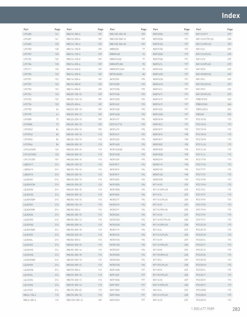
283www.erico.pentair.com 1.800.677.9089
LPC680 141
LPC681 141
LPC682 135
LPC700 120
LPC702 120
LPC704 120
LPC706 120
LPC711 120
LPC750 132
LPC751 132
LPC752 132
LPC753 132
LPC754 132
LPC755 132
LPC756 132
LPC790 62
LPC795 61
LPC858 73
LPC858L 73
LPC5962 84
LPC5963 84
LPC5964 84
LPC5966 84
LPC46740X1 136
LPC46740X2 136
LPC151250 107
LQEEH1T 214
LQEEH1V 214
LQEGH1V 214
LQJEH2C 214
LQJEH2CM 214
LQJEH2G 214
LQJEH2Q 214
LQJEH2QM 214
LQJEH2V 214
LQJEH2VM 214
LQJEH3A 214
LQJEH3D 214
LQJEH3Q 214
LQJEH3QM 214
LQJEH3X 214
LQJEH4L 214
LQJGH2C 214
LQJGH2G 214
LQJGH2Q 214
LQJGH2QM 214
LQJGH2V 214
LQJGH3Q 214
LQJGH4L 214
LQJJH2G 214
LQJJH2Q 214
LQJJH2V 214
MBJ6-150-6 110
MBJ6-200-6 110
MBJ10-200-6 109
MBJ10-300-6 109
MBJ16-100-6 109
MBJ16-100-8 109
MBJ16-150-6 109
MBJ16-150-8 109
MBJ16-200-6 109
MBJ16-200-8 109
MBJ16-250-8 109
MBJ16-300-6 109
MBJ16-300-8 109
MBJ16-500-8 109
MBJ25-100-10 109
MBJ25-150-10 109
MBJ25-200-6 109
MBJ25-200-10 109
MBJ25-200-12 109
MBJ25-250-10 109
MBJ25-300-10 109
MBJ25-500-10 109
MBJ30-100-10 110
MBJ30-150-10 110
MBJ30-200-10 110
MBJ30-250-10 110
MBJ30-300-10 110
MBJ30-500-10 110
MBJ35-100-10 110
MBJ35-150-10 110
MBJ35-200-10 110
MBJ35-250-10 110
MBJ35-250-25 110
MBJ35-300-10 110
MBJ35-500-10 110
MBJ50-100-10 110
MBJ50-150-10 110
MBJ50-200-6 110
MBJ50-200-10 110
MBJ50-200-12 110
MBJ50-200-16 110
MBJ50-200-18 110
MBJ50-250-10 110
MBJ50-300-6 110
MBJ50-300-10 110
MBJ50-300-16 110
MBJ50-300-18 110
MBJ50-500-10 110
MBJ50-500-12 110
MBJ70-300-6 110
MBJ70-300-10 110
MBJ70-300-12 110
MBJ70-300-16 110
MBJ70-300-22 110
MBJ70-500-10 110
MBJ100-250-16 109
MBJ100-250-30 109
MBJ100-500-16 109
MBJ100-500-30 109
MBNC82 77
MBNC240 76
MBNC240A 77
MBNUPCJ82 95
MBNUPCJ240 95
MPSC404SS 80
NCF222V 195
NCF223D 195
NCF223Q 195
NCF313Q 195
NCF333Q 195
NCR142C 195
NCR142G 195
NCR142Q 195
NCR161T 195
NCR161T1G 195
NCR161V 195
NCR161Y 195
NCR162C 195
NCR162G 195
NCR162G2Q 195
NCR162Q 195
NCR162V 195
NCR181T 196
NCR181V 196
NCR181Y 196
NCR182C 196
NCR182G 196
NCR182Q 196
NCR182V 196
NCR221T 196
NCR221V 196
NCR221Y 196
NCR222C 196
NCR222G 196
NCR222Q 196
NCR311V 196
NCR312C 196
NCR312G 196
NCR312Q 196
NCR332C 196
NCR332G 196
NCR332Q 196
NCR372Q 196
NDF162Q 197
NDF162V 197
NDF182Q 197
NDF182V 197
NDF183D 197
NDF183Q 197
NDF222G 197
NDF222Q 197
NDF223Q 197
NDF312Q 197
NDF313Q 197
NDF332Q 197
NDF372Q 197
NDR141L 197
NDR142C 197
NDR142G 197
NDR142Q 197
NDR161G 197
NDR161L 197
NDR161T 197
NDR161V 197
NDR161Y 197
NDR162C 197
NDR162G 197
NDR181H 197
NDR181L 197
NDR181T 198
NDR181V 198
NDR181Y 198
NDR182C 198
NDR182G 198
NDR182Q 198
NDR221V 198
NDR311V 198
NDR312C 198
NDR312G 198
NDR332G 198
NT1141G 239
NT1141GPLUS 238
NT1141L 239
NT1141LPLUS 238
NT1141V 239
NT1141VPLUS 238
NT1161G 239
NT1161G1TPLUS 238
NT1161GPLUS 238
NT1161L 239
NT1161LPLUS 238
NT1161V 239
NT1161VPLUS 238
NT1181G 239
NT1181GPLUS 238
NT1181L 239
NT1181LPLUS 238
NT1181V 239
NT1181VPLUS 238
NX1141G 239
NX1141GPLUS 238
NX1141L 239
NX1141LPLUS 238
NX1161G 239
NX1161G1T 239
NX1161G1TPLUS 238
NX1161GPLUS 239
NX1161L 239
NX1161LPLUS 239
NX1161V 239
NX1161VPLUS 239
NX1181G 239
NX1181GPLUS 239
NX1181L 239
NX1181LPLUS 239
NX1181V 239
NX1181VPLUS 239
PBB101EG 240
PBB101GH 240
PBPLUSCU 263
PBS24F 255
PCC1G1G 173
PCC1G1H 173
PCC1H1H 173
PCC1K1G 173
PCC1K1K 173
PCC1L1G 173
PCC1L1H 173
PCC1L1L 173
PCC1T1G 173
PCC1T1H 173
PCC1T1T 173
PCC1T1V 173
PCC1V1G 173
PCC1V1H 173
PCC1V1L 173
PCC1V1T 173
PCC1V1V 173
PCC1Y1G 173
PCC1Y1H 173
PCC1Y1V 173
PCC1Y1Y 173
PCC2C1G 173
PCC2C1H 173
PCC2C1K 173
PCC2C1L 173
PCC2C1T 173
PCC2C1V 173
PCC2C2C 173
PCC2G1G 173
PCC2G1H 173
PCC2G1L 173
PCC2G1T 173
PCC2G1V 173
PCC2G1Y 173
PCC2G2G 173
PCC2Q1G 173
PCC2Q1H 173
Index
Part Page Part Page Part Page Part Page Part Page
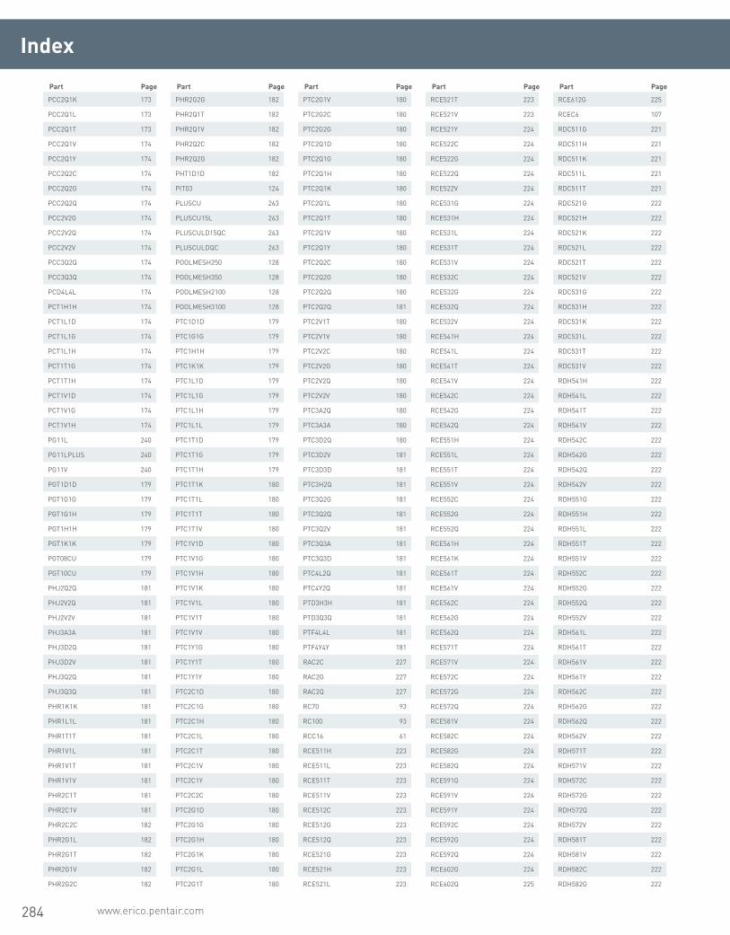
284 www.erico.pentair.com
PCC2Q1K 173
PCC2Q1L 173
PCC2Q1T 173
PCC2Q1V 174
PCC2Q1Y 174
PCC2Q2C 174
PCC2Q2G 174
PCC2Q2Q 174
PCC2V2G 174
PCC2V2Q 174
PCC2V2V 174
PCC3Q2Q 174
PCC3Q3Q 174
PCD4L4L 174
PCT1H1H 174
PCT1L1D 174
PCT1L1G 174
PCT1L1H 174
PCT1T1G 174
PCT1T1H 174
PCT1V1D 174
PCT1V1G 174
PCT1V1H 174
PG11L 240
PG11LPLUS 240
PG11V 240
PGT1D1D 179
PGT1G1G 179
PGT1G1H 179
PGT1H1H 179
PGT1K1K 179
PGT08CU 179
PGT10CU 179
PHJ2Q2Q 181
PHJ2V2Q 181
PHJ2V2V 181
PHJ3A3A 181
PHJ3D2Q 181
PHJ3D2V 181
PHJ3Q2Q 181
PHJ3Q3Q 181
PHR1K1K 181
PHR1L1L 181
PHR1T1T 181
PHR1V1L 181
PHR1V1T 181
PHR1V1V 181
PHR2C1T 181
PHR2C1V 181
PHR2C2C 182
PHR2G1L 182
PHR2G1T 182
PHR2G1V 182
PHR2G2C 182
PHR2G2G 182
PHR2Q1T 182
PHR2Q1V 182
PHR2Q2C 182
PHR2Q2G 182
PHT1D1D 182
PIT03 124
PLUSCU 263
PLUSCU15L 263
PLUSCULD15QC 263
PLUSCULDQC 263
POOLMESH250 128
POOLMESH350 128
POOLMESH2100 128
POOLMESH3100 128
PTC1D1D 179
PTC1G1G 179
PTC1H1H 179
PTC1K1K 179
PTC1L1D 179
PTC1L1G 179
PTC1L1H 179
PTC1L1L 179
PTC1T1D 179
PTC1T1G 179
PTC1T1H 179
PTC1T1K 180
PTC1T1L 180
PTC1T1T 180
PTC1T1V 180
PTC1V1D 180
PTC1V1G 180
PTC1V1H 180
PTC1V1K 180
PTC1V1L 180
PTC1V1T 180
PTC1V1V 180
PTC1Y1G 180
PTC1Y1T 180
PTC1Y1Y 180
PTC2C1D 180
PTC2C1G 180
PTC2C1H 180
PTC2C1L 180
PTC2C1T 180
PTC2C1V 180
PTC2C1Y 180
PTC2C2C 180
PTC2G1D 180
PTC2G1G 180
PTC2G1H 180
PTC2G1K 180
PTC2G1L 180
PTC2G1T 180
PTC2G1V 180
PTC2G2C 180
PTC2G2G 180
PTC2Q1D 180
PTC2Q1G 180
PTC2Q1H 180
PTC2Q1K 180
PTC2Q1L 180
PTC2Q1T 180
PTC2Q1V 180
PTC2Q1Y 180
PTC2Q2C 180
PTC2Q2G 180
PTC2Q2Q 180
PTC2Q2Q 181
PTC2V1T 180
PTC2V1V 180
PTC2V2C 180
PTC2V2G 180
PTC2V2Q 180
PTC2V2V 180
PTC3A2Q 180
PTC3A3A 180
PTC3D2Q 180
PTC3D2V 181
PTC3D3D 181
PTC3H2Q 181
PTC3Q2G 181
PTC3Q2Q 181
PTC3Q2V 181
PTC3Q3A 181
PTC3Q3D 181
PTC4L2Q 181
PTC4Y2Q 181
PTD3H3H 181
PTD3Q3Q 181
PTF4L4L 181
PTF4Y4Y 181
RAC2C 227
RAC2G 227
RAC2Q 227
RC70 93
RC100 93
RCC16 61
RCE511H 223
RCE511L 223
RCE511T 223
RCE511V 223
RCE512C 223
RCE512G 223
RCE512Q 223
RCE521G 223
RCE521H 223
RCE521L 223
RCE521T 223
RCE521V 223
RCE521Y 224
RCE522C 224
RCE522G 224
RCE522Q 224
RCE522V 224
RCE531G 224
RCE531H 224
RCE531L 224
RCE531T 224
RCE531V 224
RCE532C 224
RCE532G 224
RCE532Q 224
RCE532V 224
RCE541H 224
RCE541L 224
RCE541T 224
RCE541V 224
RCE542C 224
RCE542G 224
RCE542Q 224
RCE551H 224
RCE551L 224
RCE551T 224
RCE551V 224
RCE552C 224
RCE552G 224
RCE552Q 224
RCE561H 224
RCE561K 224
RCE561T 224
RCE561V 224
RCE562C 224
RCE562G 224
RCE562Q 224
RCE571T 224
RCE571V 224
RCE572C 224
RCE572G 224
RCE572Q 224
RCE581V 224
RCE582C 224
RCE582G 224
RCE582Q 224
RCE591G 224
RCE591V 224
RCE591Y 224
RCE592C 224
RCE592G 224
RCE592Q 224
RCE602G 224
RCE602Q 225
RCE612G 225
RCEC6 107
RDC511G 221
RDC511H 221
RDC511K 221
RDC511L 221
RDC511T 221
RDC521G 222
RDC521H 222
RDC521K 222
RDC521L 222
RDC521T 222
RDC521V 222
RDC531G 222
RDC531H 222
RDC531K 222
RDC531L 222
RDC531T 222
RDC531V 222
RDH541H 222
RDH541L 222
RDH541T 222
RDH541V 222
RDH542C 222
RDH542G 222
RDH542Q 222
RDH542V 222
RDH551G 222
RDH551H 222
RDH551L 222
RDH551T 222
RDH551V 222
RDH552C 222
RDH552G 222
RDH552Q 222
RDH552V 222
RDH561L 222
RDH561T 222
RDH561V 222
RDH561Y 222
RDH562C 222
RDH562G 222
RDH562Q 222
RDH562V 222
RDH571T 222
RDH571V 222
RDH572C 222
RDH572G 222
RDH572Q 222
RDH572V 222
RDH581T 222
RDH581V 222
RDH582C 222
RDH582G 222
Index
Part Page Part Page Part Page Part Page Part Page
285www.erico.pentair.com 1.800.677.9089
Index
RDH582Q 223
RDH582V 223
RDH591V 223
RDH591Y 223
RDH592C 223
RDH592G 223
RDH592Q 223
RDH592V 223
RDH602G 223
RDH602Q 223
RDH612G 223
RDH612Q 223
RDM512G 223
RDM512Q 223
RDM522C 223
RDM522G 223
RDM522Q 223
RDM522V 223
RDM532C 223
RDM532G 223
RDM532Q 223
RDM532V 223
REP16120L 59
RHC512C 225
RHC512Q 225
RHC521H 225
RHC521L 225
RHC521V 225
RHC522C 225
RHC522G 225
RHC522Q 225
RHC531H 225
RHC531L 225
RHC531T 225
RHC531V 225
RHC532C 225
RHC532G 225
RHC532Q 225
RHC541L 225
RHC541V 225
RHC542C 225
RHC542G 225
RHC542Q 225
RJC522C 226
RJC522G 226
RJC522Q 226
RJC522V 226
RJC531H 226
RJC531K 226
RJC531L 226
RJC531T 226
RJC531V 226
RJC531Y 226
RJC532C 226
RJC532G 226
RJC532Q 226
RJC532V 226
RJC541H 226
RJC541L 226
RJC541T 226
RJC541V 226
RJC542C 226
RJC542G 226
RJC542Q 226
RJC542V 226
RJE551L 226
RJE551T 226
RJE551V 226
RJE552C 226
RJE552G 226
RJE552Q 226
RJE561L 226
RJE561T 226
RJE561V 226
RJE562C 226
RJE562Q 226
RJE562V 226
RJE571L 226
RJE571T 226
RJE571V 226
RJE572C 226
RJE572G 227
RJE572Q 227
RJE572V 227
RJE581T 227
RJE581V 227
RJE582C 227
RJE582G 227
RJE582Q 227
RJE582V 227
RJE591V 227
RJE592C 227
RJE592G 227
RJE592Q 227
RJE592V 227
RJE602C 227
RRA521H 219
RRA521K 219
RRA521L 219
RRA521T 219
RRA521V 219
RRA521Y 219
RRA531D 219
RRA531G 219
RRA531H 219
RRA531K 219
RRA531L 220
RRA531T 220
RRA531V 220
RRA531Y 220
RRA541G 220
RRA541H 220
RRA541L 220
RRA541T 220
RRA541V 220
RRA541Y 220
RRA551L 220
RRA551T 220
RRA551V 220
RRA561L 220
RRA561T 220
RRA561V 220
RRA561Y 220
RRA571T 220
RRA571V 220
RRA581H 220
RRA581T 220
RRA581V 220
RRA591H 220
RRA591L 220
RRA591T 220
RRA591V 220
RRC511H 220
RRC511L 220
RRC511T 220
RRC511V 221
RRC512C 221
RRC512G 221
RRC512L 221
RRC512Q 221
RRC512V 221
RRC522C 221
RRC522G 221
RRC522L 221
RRC522Q 221
RRC522V 221
RRC532C 221
RRC532G 221
RRC532L 221
RRC532Q 221
RRC532V 221
RRH542G 221
RRH542L 221
RRH542Q 221
RRH542V 221
RRH552C 221
RRH552G 221
RRH552L 221
RRH552Q 221
RRH552V 221
RRH562C 220
RRH562G 220
RRH562L 220
RRH562Q 220
RRH562V 220
RRH572C 220
RRH572G 220
RRH572L 220
RRH572Q 220
RRH572V 220
RRH582C 220
RRH582G 220
RRH582L 220
RRH582Q 220
RRH582V 220
RRH592C 220
RRH592G 220
RRH592L 220
RRH592Q 220
RRH592V 220
RRH602L 221
RRH602Q 221
RRH612C 221
RRH612L 221
RRH612Q 221
S01 255
S01F 255
S02F 255
S03F 255
S05F 255
S06F 255
S07 255
S07F 255
S09F 255
S17F 255
S20F 255
S429F1C12 255
S429F1F 255
S429F1J 255
S429F1N 255
S429F1N12 255
S429F1S 255
S429F1W 255
S429F1W12 255
S429F2A 255
S429F2A12 255
S429F2E 255
S429F2E16 255
S429F2J 255
S429F2J16 255
S429F2N 255
S429F2N16 255
S429F2S 255
S429F2S16 255
S429F2W16 255
S429F3B16 255
S429F3F 255
S429F3F16 256
S429F3K16 256
S429F3M12 256
S429F3N16 256
S429F3S20 256
S429F4C16 256
S429F4K16 256
S429F4M16 256
S429F4N24 256
S429F4P16 256
S429F4T20 256
S429F4X24 256
S429F5A24 256
S429F5B24 256
S429F5E24 256
S429F5F24 256
S429FY922 256
S4291F 256
S4291J 256
S4291N12 256
S4291W 256
S4291W12 256
S4292A 256
S4292E 256
S4292J 256
S4292J16 256
S4292N 256
S4292S 256
S4293F 256
SBCS0810 67
SBCS1314 67
SBD50 260
SBD51 260
SBD55 260
SBS09C 255
SBS11C 255
SBS12C 255
SBS13C 255
SCEC25 108
SCEC35 108
SCEC50 108
SCEC95 108
SCEC120 108
SCEC150 108
SCEC185 108
SDT34 163
SDT58 163
SP58 57
SP58B916 57
SRC15 61
SRGBD100 129
SRGBE100 129
SRGBG100 129
Part Page Part Page Part Page Part Page Part Page

286 www.erico.pentair.com
Index
SRGC46 78
SRGC46BR 96
SSC1D 172
SSC1G 172
SSC1H 172
SSC1K 172
SSC1L 172
SSC1T 172
SSC1V 172
SSC1Y 172
SSC2C 172
SSC2G 172
SSC2Q 172
SSC2V 172
SSC3A 172
SSC3D 172
SSC3H 172
SSC3Q 172
SSC4L 172
SSD4Y 172
SST1G 172
SST1K 172
SST1L 172
SST1T 172
SST1V 172
T111 266
T302A 265
T306 268
T313 264
T314 264
T314A 264
T315 266
T315A 266
T319 259
T320 261
T320A 262
T321 267
T321A 267
T328 254
T328D 254
T331 267
T336 264
T343 266
T343R 266
T372A 259
T378L 269
T393 269
T394 265
T396 267
T403 261
T416A 123
T416B 122
T416BH 122
T416C 123
T416CKEY 123
T416D 124
T416E 124
T416F 124
T427 257
TAC1D1D 174
TAC1G1G 174
TAC1G1H 174
TAC1H1H 174
TAC1K1K 174
TAC1K1L 174
TAC1L1H 174
TAC1L1L 174
TAC1T1G 174
TAC1T1H 174
TAC1T1K 174
TAC1T1L 174
TAC1T1T 174
TAC1T1V 174
TAC1V1G 174
TAC1V1H 174
TAC1V1K 174
TAC1V1L 174
TAC1V1T 174
TAC1V1V 175
TAC1V1Y 175
TAC1Y1L 175
TAC1Y1T 175
TAC2C1G 175
TAC2C1H 175
TAC2C1K 175
TAC2C1L 175
TAC2C1T 175
TAC2C1V 175
TAC2C1Y 175
TAC2C2C 175
TAC2G1G 175
TAC2G1H 175
TAC2G1K 175
TAC2G1L 175
TAC2G1T 175
TAC2G1V 175
TAC2G1Y 175
TAC2G2C 175
TAC2G2G 175
TAC2Q1G 175
TAC2Q1H 175
TAC2Q1K 175
TAC2Q1L 175
TAC2Q1T 175
TAC2Q1V 175
TAC2Q1Y 175
TAC2Q2C 175
TAC2Q2G 175
TAC2Q2Q 175
TAC2V1T 175
TAC2V1V 175
TAC2V1Y 175
TAC2V2C 175
TAC2V2G 175
TAC2V2Q 175
TAC2V2V 175
TAC3A1T 175
TAC3A1V 175
TAC3A2C 175
TAC3A2G 175
TAC3A2Q 175
TAC3A2V 175
TAC3A3A 175
TAC3D1V 175
TAC3D1Y 175
TAC3D2C 175
TAC3D2G 175
TAC3D2Q 175
TAC3D2V 175
TAC3D3A 175
TAC3D3D 175
TAC3H2C 176
TAC3H2G 176
TAC3H2Q 176
TAC3H2V 176
TAC3H3A 176
TAC3H3D 176
TAC3H3H 176
TAC3Q2C 176
TAC3Q2G 176
TAC3Q2Q 176
TAC3Q2V 176
TAC3Q3A 176
TAC3Q3D 176
TAC3Q3Q 176
TAC4L2G 176
TAC4L2Q 176
TAC4L2V 176
TAC4L3D 176
TAC4Y2G 176
TAC4Y2Q 176
TAC4Y3D 176
TAD3Q4L 176
TAD3X3X 176
TAD4L3H 176
TAD4L3Q 176
TAD4L4L 176
TAD4Y2V 176
TAD4Y3Q 176
TAD4Y4L 176
TAD4Y4Y 176
TDSGABC14 154
TDSGAP 156
TDSGAPA14 154
TDSGAPC14 155
TDSGAS 156
TDSGAWB 156
TDSGAWB17 155
TGBA12L06P 150
TGBA12L06PT 150
TGBA16L08P 150
TGBA16L08PT 150
TGBA18L10P 150
TGBA18L10PT 150
TGBA20L12P 150
TGBA20L12PT 150
TGBA24L14P 150
TGBA24L14PT 150
TGBA29L18P 150
TGBA29L18PT 150
TGBSPLICEKIT 151
TGC2/0 70
TMGBA12L15P 150
TMGBA12L15PT 151
TMGBA16L19P 150
TMGBA16L19PT 151
TMGBA18L23P 150
TMGBA18L23PT 151
TMGBA20L27P 150
TMGBA20L27PT 151
TMGBA24L33P 151
TMGBA24L33PT 151
TMGBA29L41P 151
TMGBA29L41PT 151
TMGBSPLICEKIT 151
UGP719 133
UGP719BP5 133
UGP719SBP5 133
UGP738 133
UGP738P5 133
UGP738P10 133
UGP738SBP5 133
VBC1G 203
VBC1H 203
VBC1HV3C 203
VBC1K 203
VBC1KV3C 203
VBC1L 203
VBC1LV3C 203
VBC1LV5C 203
VBC1LV8C 203
VBC1LV21C 203
VBC1T 203
VBC1TV3C 203
VBC1TV5C 203
VBC1TV8C 203
VBC1TV21C 203
VBC1V 203
VBC1VV3C 203
VBC1VV5C 203
VBC1VV8C 203
VBC1VV21C 203
VBC1Y 203
VBC1YV3C 203
VBC2C 203
VBC2CV3C 203
VBC2CV5C 203
VBC2CV8C 203
VBC2CV21C 203
VBC2G 203
VBC2GV3C 204
VBC2GV5C 204
VBC2GV8C 204
VBC2GV21C 204
VBC2Q 204
VBC2QV3C 204
VBC2QV5C 204
VBC2QV8C 204
VBC2QV21C 204
VBC2V 204
VBC2VV5C 204
VBC3A 204
VBC3H 204
VBR3Q 204
VC62 79
VC207IT 71
VFC1G 204
VFC1GV3C 204
VFC1H 204
VFC1HV3C 204
VFC1K 204
VFC1KV3C 204
VFC1L 204
VFC1LV3C 204
VFC1LV8C 204
VFC1LV21C 204
VFC1T 204
VFC1TV3C 205
VFC1TV5C 205
VFC1TV21C 205
VFC1V 205
VFC1VV3C 205
VFC1VV5C 205
VFC1VV8C 205
VFC1Y 205
VFC2C 205
VFC2CV3C 205
VFC2CV8C 205
VFC2G 205
VFC2GV3C 205
Part Page Part Page Part Page Part Page Part Page

287www.erico.pentair.com 1.800.677.9089
Index
VFC2GV5C 205
VFC2GV8C 205
VFF3Q 205
VFR2Q 205
VFR2QV3C 205
VFR2QV5C 205
VFR2QV8C 205
VFR2QV21C 205
VFR2V 205
VFR3A 205
VFR3D 205
VFR3H 205
VGC1G 206
VGC1H 206
VGC1L 206
VGC1T 206
VGC1V 206
VGC1Y 206
VGC2C 206
VGC2G 206
VNC1GLH 208
VNC1HLH 208
VNC1HRH 208
VNC1LLH 208
VNC1LRH 208
VNC1TLH 208
VNC1TRH 208
VNC1VLH 208
VNC1VRH 208
VNC2CLH 208
VNC2CRH 208
VNC2GLH 208
VNC2GRH 208
VNC2LLH 208
VNC2LRH 208
VNC2QLH 208
VNC2QRH 208
VNC2VLH 208
VNC2VRH 208
VSC1G 201
VSC1GV3C 201
VSC1GV5C 201
VSC1GV8C 201
VSC1H 201
VSC1HV3C 201
VSC1HV8C 201
VSC1HV21C 201
VSC1K 201
VSC1KV3C 201
VSC1KV5C 201
VSC1KV8C 201
VSC1L 201
VSC1LV3C 201
VSC1LV5C 201
VSC1LV8C 201
VSC1LV21C 201
VSC1PV3C 202
VSC1T 202
VSC1TV3C 202
VSC1TV5C 202
VSC1TV8C 202
VSC1TV21C 202
VSC1V 202
VSC1VV3C 202
VSC1VV5C 202
VSC1VV8C 202
VSC1VV21C 202
VSC1Y 202
VSC1YV3C 202
VSC1YV5C 202
VSC1YV8C 202
VSC1YV21C 202
VSC2C 202
VSC2CV3C 202
VSC2CV5C 202
VSC2CV8C 202
VSC2CV21C 202
VSC2G 202
VSC2GV3C 202
VSC2GV5C 202
VSC2GV8C 202
VSC2GV21C 202
VSC2Q 202
VSC2QV3C 202
VSC2QV5C 202
VSC2QV8C 202
VSC2QV21C 202
VSC2V 202
VSC3A 202
VSC3D 202
VSC3H 202
VSC3Q 202
VSP1K 202
VSP1T 202
VST1G 202
VST1H 202
VST1L 203
VTC1G 206
VTC1H 206
VTC1K 206
VTC1L 206
VTC1LV3C 206
VTC1LV5C 206
VTC1T 206
VTC1TV3C 206
VTC1TV5C 206
VTC1TV8C 207
VTC1V 207
VTC1VV3C 207
VTC2C 207
VTC2CV3C 207
VTC2G 207
VTC2GV3C 207
VTC2Q 207
VTC2QV3C 207
VTC2QV5C 207
VTC2QV21C 207
VTC2V 207
VTD3Q 207
VVC1G 207
VVC1GV3C 207
VVC1H 207
VVC1K 207
VVC1L 207
VVC1LV3C 207
VVC1T 207
VVC1TV3C 207
VVC1V 207
VVC1VV3C 207
VVC1VV21C 207
VVC1Y 208
VVR2C 208
VVR2CV3C 208
VVR2G 208
VVR2GV3C 208
VVR2GV5C 208
VVR2GV21C 208
VVR2Q 208
VVR2QV3C 208
VVR2QV8C 208
VVR2QV21C 208
VVR2V 208
WD80 260
WD82 260
WD83 260
WD84 260
WD85 260
WD87 260
WD88 260
WD94 260
WGRS200 125
XAC1G1G 176
XAC1H1H 176
XAC1K1K 176
XAC1L1L 176
XAC1T1T 176
XAC1V1H 176
XAC1V1L 176
XAC1V1T 176
XAC1V1V 177
XAC1Y1Y 177
XAC2C1V 177
XAC2C2C 177
XAC2G1T 177
XAC2G1V 177
XAC2G2C 177
XAC2G2G 177
XAC2Q1V 177
XAC2Q1Y 177
XAC2Q2C 177
XAC2Q2G 177
XAC2Q2Q 177
XAC2V1V 177
XAC2V2C 177
XAC2V2G 177
XAC2V2Q 177
XAC2V2V 177
XAC3A2G 177
XAC3A2Q 177
XAC3A2V 177
XAC3A3A 177
XAC3D2C 177
XAC3D2G 177
XAC3D2Q 177
XAC3D2V 177
XAC3D3D 177
XAC3H3H 177
XAC3Q2G 177
XAC3Q2Q 177
XAD3Q3Q 177
XAD3X3X 177
XAD4L2Q 177
XAD4Y2Q 177
XB32C2C 178
XB32G2G 178
XB32L2L 178
XB32Q2Q 178
XB32V2V 178
XB43D3D 178
XBC1K1K 178
XBC1L1L 178
XBC1T1T 178
XBC1V1L 178
XBC1V1V 178
XBC1Y1Y 178
XBC2C1V 178
XBK3X3X 178
XBK4L3Q 178
XBK4L4L 178
XBK4Y3Q 178
XBK4Y4Y 178
XBM2C2C 178
XBM2G2G 178
XBM2L2L 178
XBM2Q2Q 178
XBM2V2V 178
XBP1G1G 178
XBP1H1H 178
XBQ2C2C 178
XBQ2G1V 178
XBQ2G2C 178
XBQ2G2G 178
XBQ2Q2C 178
XBQ2Q2G 178
XBQ2Q2Q 178
XBQ2V2G 178
XBQ2V2Q 178
XBQ2V2V 179
XBV3A3A 179
XBV3D3D 179
XBV3H3H 179
XBV3Q3Q 179
XL15 237
XL25 237
XL32 237
XL45 237
XL65 237
XL90 237
XL115 237
XL150 237
XL200 237
XL250 237
XL300 237
XL400 237
XL500 237
XL600 237
XL750 237
XLB971A1 263
XLB974B2 268
ZWP1J 81
Part Page Part Page Part Page Part Page Part Page

288 www.erico.pentair.com

289www.erico.pentair.com 1.800.831.7133

290 www.erico.pentair.com

291www.erico.pentair.com 1.800.831.7133

E1243C-NAEN 59M0216
Pentair products shall be installed and used only as indicated in Pentair’s product instruction sheets and training materials. Instruction sheets are available at www.erico.pentair.com and from your Pentair customer service representative. Improper installation, misuse, misapplication or other failure to completely follow Pentair’s instructions and warnings may cause product malfunction, property damage, serious bodily injury and death and/or void your warranty.
© 2009 – 2010, 2016 Pentair All Rights ReservedPentair, CADDY, CADWELD, CRITEC, ERICO, ERIFLEX and LENTON are owned by Pentair or its global affiliates. All other trademarks are the property of their respective owners. Pentair reserves the right to change specifications without prior notice.
ERICO · 1.800.677.9089 · www.erico.pentair.com
ENGINEERED ELECTRICAL FASTENING SYSTEMSSolon, OHTel: +1.800.677.9089
TECHNICAL SOLUTIONS