EPPE CX | PX .
[ENG ]
KoCoS Messtechnik AGSüdring 4234497 Korbach, GermanyTel. +49 5631 9596-40Fax +49 5631 [email protected] K O C O S M E S S T E C H N I K A G
EPPE.
KO C O S - T H E T E C H N O L O G Y G R O U P | W H E R E P R E C I S I O N M E E T S Q UA L I T Y
Subj
ect t
o ch
ange
with
out p
rior n
otic
e |
2018
05 I
© K
oCoS
Mes
stec
hnik
AG
Power Quality Analyser

Multi-functional measurement technology for fully automatic power monitoring
EPPE CX and EPPE PX are powerful, multi-functional measuring instruments for comprehensive, continuous and fully automatic power monitoring at all voltage levels.
Various different types of signal inputs for voltages and currents as well as optional sensor inputs and outputs make the devices extremely flexible to use. EPPE CX | PX can be tailored to meet the individual needs and requirements of the user.
The applications listed below are given as examples of the wide range of different uses of the devices:
n Power quality analysisn Power quality monitoringn Differential current measurementn Fault analysisn Measurement of harmonicsn Monitoring and analysis of renewable power systemsn Network optimisationn Load managementn Monitoring to EN 50160n Fault locationn Trend recordingn Critical load monitoringn Consumption measurements, e.g. for load optimisation
EPPE PXThe portable solution in a carrying caseEPPE PX has been specially developed for mobile measurements and installation monitoring. Sensor inputs, direct inputs for current measurement and galvanically isolated voltage inputs make the device extremely flexible to use. The rugged carrying case protects the measuring device even in harsh environmental conditions.
EPPE CX Stationary, fully automatic monitoring system for panel mounting
EPPE CX is ideal for fully automatic monitoring with continuous measurement data transfer to a central data system. Evaluation is performed automatically and a built-in alarm system informs the employees responsible should a fault occur.
EPPE CX | PX
32
54
Inputs and outputs
Safe to operate even under extreme conditionsAll analog and binary inputs and outputs and all interfaces are galvanically isolated and meet stringent occupational health and safety requirements. Their excellent immunity to electro-magnetic disturbances ensures smooth operation even when conditions are extreme.
Analog inputsEPPE CX | PX analog channels are generally sampled at a rate of 200 kHz. Because of the absolutely linear frequency response, all the inputs provide high accuracy (< 0.05%) across the entire measuring range.
Features:n 16 bit A/D convertern Sampling rate 200 kHzn Accuracy < 0.05% (of range)n Overcurrent-protected up to 500 A for max. 1 sec. EppE CXn 4 x 600 V Ph-N, 4 x 10 A (measurements on protection or measurement transformers)
EppE PXn 4 x 600 V Ph-N, 4 x 32 A, 4 x 3 V Ph-N (measurements on protection or measurement transformers and via external current sensors)
EppE CX
Binary inputs and outputsThe binary inputs are divided into groups, each of which has a common reference point. The special input circuitry of the binary inputs is designed for operation with voltages between 24 V and 300 V and effectively suppresses the detection of transients which can be caused by switching operations, for example. Freely configurable relay outputs can be used to indicate status signals, alarm signals or limit value violations to control systems, for example.
Features CX:n16 binary inputsn Response threshold: 24...300 VDC, activation range is configurablen Resolution: 0.1 msn 6 electronic relay outputs
Features pX:n8 binary inputsn 2 groups of 4 channelsn Response threshold: 24...300 VDCn Resolution: 0.1 msn 2 potential-free relay contacts
Sensor inputsThe storage and analysis of environmental factors are becoming increasingly important for measuring systems which are used for monitoring and analysis, particularly for those used in renewable power generating systems (PV systems, wind power plants, etc.).Factors such as light irradiation, ambient temperature, module temperature, humidity, wind speed, wind direction, sound intensity, generator temperature, etc. can provide helpful information for analysis or fault diagnostics.
The EPPE CX | PX power quality analysers enable these measurement values to be recorded with the aid of sensor measurement inputs and can issue alarm signals to the user if pre-defined limit values are exceeded.
In the case of a malfunction, this additional measurement data is helpful for the purposes of analysis and for the development of remedial measures. The sensor measurement inputs also allow a further current measurement to be carried out which can be used for the identification and elimination of leakage currents.
EppE PX

76
Data communication via UMTS routerAs reliance on renewable energy sources grows, increasing numbers of power quality analysers are used in plants which do not have a wired communication network. Automatic data download using a mobile network via UMTS, for example, is recommended as an alternative to downloading data onto a USB flash drive.
This means that communication and data transfer are fully independent of any kind of wired infrastructure. What is more, even in rural areas and small towns it is possible to reach a high data transmission rate (of up to 100 Mbit/s) when downloading the measurement data. The UMTS router establishes an Internet connection and the data can be transferred easily and reliably to a central server (database) by means of a VPN tunnel. The portable EPPE PX features separate connections to supply power to a UMTS router.
EppE PXnEthernetn USB (active/passive)n GSM/GPRS modemn UMTS router
CommunICatIon Multi-processor systemEPPE CX | PX feature an integrated multi-processor system with separate processors for real-time measurements, for the user interface and the communications interfaces. This is the only way to ensure user-friendly operation, fast and reliable data transfer and easy integration into any network.
Configuration with USB flash driveIf neither a wired nor a wireless communication network is available, configuration can also be carried out directly using a USB flash drive. Saved measurement data can also be transferred quickly and easily to a USB flash drive without a direct communication connection.
Communication interfacesThe measuring systems provide the following interfaces for integration in communication networks:
EppE CXnEthernetn USB (active/passive)n RS485n RS232n GSM/GPRS modemn UMTS router
Integrated web serverEPPE CX | PX have an integrated web server which allows users to access relevant measurement data from any PC with any Internet browser. There is no need to install special software.
Radio linkUMTS router, GSM/GPRS modem
Web server
Remote link Network capabilityEthernet, optical Ethernet (FO)
Direct linkUSB flash drive

8
IEC 61850 || ModbusFor integration in substation control and protection or for the exchange of data with other systems, EPPE CX can use a range of data protocols, including IEC 61850 and Modbus.These communications services run in parallel, enabling data to be exchanged quickly between different systems.
OfficeNetwork
Evaluation PCs
Service & evaluation
Substation network
LAN / WAN / GSM
Data server & administration
Evaluation at station level
Firewall
data mEmory
The measurement data can be recorded safely and reliably in the internal flash memory and can be transferred quickly and conveniently to a PC. No measurement data is lost, even when there is an interruption to the power supply.
powEr supply
Power supply unitsThe standard wide-range power supply unit allows flexible powering.
EppE CX:Wide-range power supply unit: 85...265 VAC / 90...275 VDC
EppE PX:External wide-range power supply unit: 100...240 VAC (100...350 VDC)
Internal DC power supply unit: 9…18 VDC
Internal emergency power supplyThe device is automatically supplied with power for a period of up to 8 seconds should there be a short-term interruption to the voltage supply.The emergency power supply is completely maintenance-free!It is not necessary for the battery of the EPPE CX | PX to be replaced by the manufacturer as is often the case with similar systems after just one year.
9

11
The KoCoS-Interlink interface can be used to synchronize the time of a number of EPPE devices and to pass on trigger information. This results in a significant reduction in costs as only one measuring device per location needs to be synchronized as the „master“ system.The cross-triggering function can also be used to start fault recordings absolutely simultaneously on a number of EPPE systems at once.
tImE synChronIzatIon
Power quality analysis and fault analysis with full area coverage call for precise time synchronization. Only when measured values are recorded by a number of devices absolutely simultaneously, is it possible to compare them with one another and analyse them correctly.EPPE CX | PX can use the following methods of time synchronization:
EppE CX GPS DCF77 NTP/SNTP IRIG-B Synchronization to PC time Seconds and minutes pulse KoCoS Interlink interface
EppE PX GPS DCF77 NTP/SNTP Synchronization to PC time KoCoS Interlink interface
Gateway
DatabaseUMTSrouter
UMTSrouter
USB flash drive
Network
Evaluation unit
Data importComtradePQDIFCSV
Data exportComtradePQDIFCSV
Mobilemeasurement
GPS time synchronization
GatewayInterlink Interlink
Mobile network
Internet
10

1312
rECordIng FunCtIons
Power quality recordingThe continuous recording of all power system parameters allows comprehensive power quality analysis to DIN EN 50160 or
quality criteria defined by the individual user.Characteristic values are captured and calculated to IEC 61000-4-30 class A, IEC 61000-4-7 and IEC 61000-4-15. Automatic evaluation and the creation of quality reports as PDF files make it easy to provide proof of quality whenever required, even without specialist knowledge.
Continuous data recordingThe data logger function records measurement data
continuously. The recorded data can be downloaded to a central computer without interrupting the measurement.As a result, data can be recorded continuously for a number of years. The averaging intervals can be configured in line with individual requirements. For each averaging interval, the mean value for the given time and the highest and lowest single RMS values for a system cycle are recorded with an exact time stamp. Long-term recordings provide comprehensive information on the entire power system, expose slow changes, as can result from a changing load or generator structure, and
reveal potential for energy savings.
Event recording Event recording provides information on the time, level and duration of limit value violations and a classification of events to EN50160, for example. If required, the event signatures can also be recorded with a time resolution of half a period.
Fast fault recording for power system faultsWhen a limit value violation occurs, all analog and binary signals are recorded with a configurable resolution of 100 Hz to 30 kHz. The recording comprises separately configurable time windows for pre-fault, fault and post-fault periods. The fault recording duration can either be set to a fixed length or can be controlled by the actual duration of the event.
Slow fault recordingIn addition to the analog and digital signals which are measured directly, the RMS fault recorder can also record all the quantities calculated on the basis of these signals, such as frequency, unbalance, positive sequence system, negative sequence system and zero sequence system, active power, reactive power and apparent power, harmonics etc. The sampling rate can be set between 1 Hz and double the system frequency (100 Hz / 120 Hz). The recording is ideal for detecting and assessing slow processes, such as power swings, or for generator monitoring.
Recording of digital events and statesBinary inputs are primarily used to read in signals from protection relays, circuit breaker positions or machine conditions, for example, which are of decisive importance for the analysis of fault records. The binary inputs can also be used to trigger fault records in order to obtain a high-resolution record of the state of the power system at the moment of switching.
Energy meterPower consumption can be monitored using the built-in energy meter with accuracy class 0.2S and optimised with the aid of long-term trend analysis. Active, reactive and apparent energy can be recorded and analysed extremely precisely.
1514
opEr atIng ConCEpt
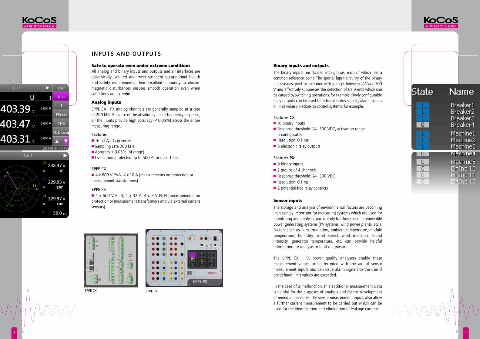
Operation via touch screenThe device can be operated easily using the ergonomic touch screen. All functions and measured value displays can be selected directly from the main menu. All important measured values and status information can be seen at a glance. Alternatively, the device can also be operated with the aid of the function keys.
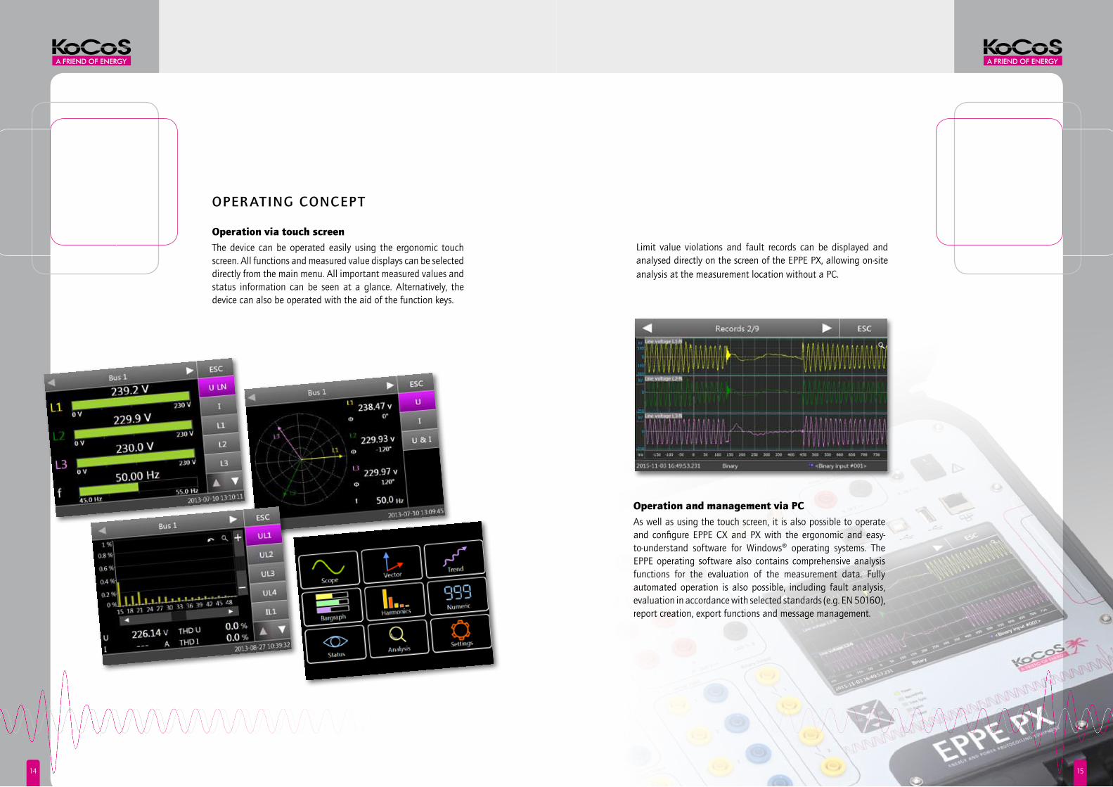
Limit value violations and fault records can be displayed and analysed directly on the screen of the EPPE PX, allowing on-site analysis at the measurement location without a PC.
Operation and management via PCAs well as using the touch screen, it is also possible to operate and configure EPPE CX and PX with the ergonomic and easy-to-understand software for Windows® operating systems. The EPPE operating software also contains comprehensive analysis functions for the evaluation of the measurement data. Fully automated operation is also possible, including fault analysis, evaluation in accordance with selected standards (e.g. EN 50160), report creation, export functions and message management.

1716
soF t warE For opEr atIon and EvaluatIon
The ergonomic software designed in accordance with the Windows® Fluent concept is designed to meet real-world requirements and can be put to a wide variety of different uses, ranging from the operation of an individual measuring device to the administration of complex groups of EPPE measuring devices. There are 2 different versions of the software which differ in functionality and in the number of devices to be managed.
“Professional“ EPPE operating software Full range of functions Management of up to 5 EPPE measuring instruments
“Premium“ EPPE operating softwareFull range of functions Management of an unlimited number of EPPE measuring instruments
The scope of delivery of EPPE PX includes EPPE software for operation and evaluation with a full range of functions for managing one measuring instrument.
All the versions of the software are very easy to use and feature a variety of functions, including the following:
Flexible configuration for optimum adaptation to a wide range of measurement tasks
Remote configuration/administration
Fully automatic operation of the measuring system with· remote data transmission· archiving of records in a database· printout or dispatch of fault reports and PQ quality reports· export to common PQ and fault record formats· online monitoring
Easy-to-use analysis tool with automatic evaluation and assessment of power quality to international standards (e.g. EN 50160)
Multi-screen capability (optimum overview, a wealth of informa-tion at a glance)
19
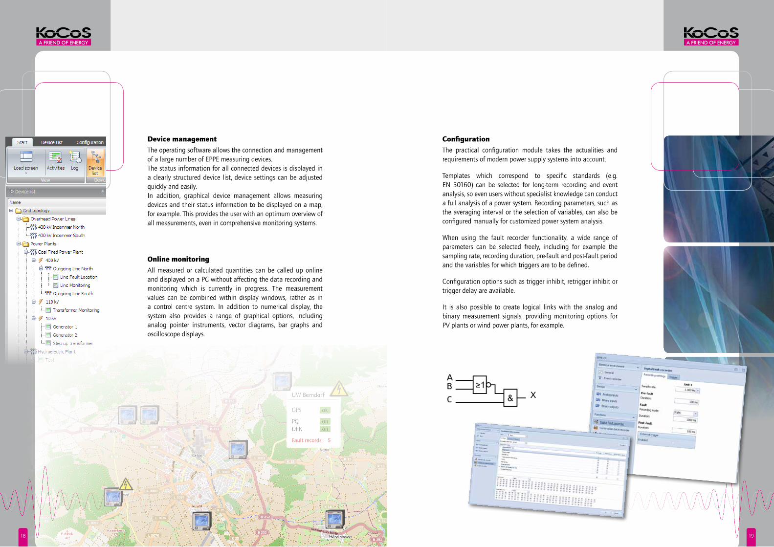
ConfigurationThe practical configuration module takes the actualities and requirements of modern power supply systems into account.
Templates which correspond to specific standards (e.g. EN 50160) can be selected for long-term recording and event analysis, so even users without specialist knowledge can conduct a full analysis of a power system. Recording parameters, such as the averaging interval or the selection of variables, can also be configured manually for customized power system analysis.
When using the fault recorder functionality, a wide range of parameters can be selected freely, including for example the sampling rate, recording duration, pre-fault and post-fault period and the variables for which triggers are to be defined.
Configuration options such as trigger inhibit, retrigger inhibit or trigger delay are available.
It is also possible to create logical links with the analog and binary measurement signals, providing monitoring options for PV plants or wind power plants, for example.
Device management The operating software allows the connection and management of a large number of EPPE measuring devices.The status information for all connected devices is displayed in a clearly structured device list, device settings can be adjusted quickly and easily.In addition, graphical device management allows measuring devices and their status information to be displayed on a map, for example. This provides the user with an optimum overview of all measurements, even in comprehensive monitoring systems.
Online monitoringAll measured or calculated quantities can be called up online and displayed on a PC without affecting the data recording and monitoring which is currently in progress. The measurement values can be combined within display windows, rather as in a control centre system. In addition to numerical display, the system also provides a range of graphical options, including analog pointer instruments, vector diagrams, bar graphs and oscilloscope displays.
18
UW Berndorf
GPS ok
PQ onDFR on
Fault records: 5
2120
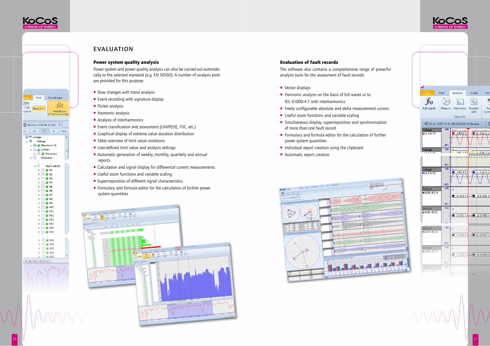
EvaluatIon Power system quality analysisPower system and power quality analysis can also be carried out automati-cally to the selected standard (e.g. EN 50160). A number of analysis tools are provided for this purpose:
Slow changes with trend analysis
Event recording with signature display
Flicker analysis
Harmonic analysis
Analysis of interharmonics
Event classification and assessment (UNIPEDE, ITIC, etc.)
Graphical display of extreme value duration distribution
Table overview of limit value violations
User-defined limit value and analysis settings
Automatic generation of weekly, monthly, quarterly and annual reports
Calculation and signal display for differential current measurements
Useful zoom functions and variable scaling
Superimposition of different signal characteristics
Formulary and formula editor for the calculation of further power system quantities
Evaluation of fault recordsThe software also contains a comprehensive range of powerful analysis tools for the assessment of fault records:
Vector displays
Harmonic analysis on the basis of full waves or to
IEC 61000-4-7 with interharmonics
Freely configurable absolute and delta measurement cursors
Useful zoom functions and variable scaling
Simultaneous display, superimposition and synchronization of more than one fault record
Formulary and formula editor for the calculation of further power system quantities
Individual report creation using the clipboard
Automatic report creation
2322
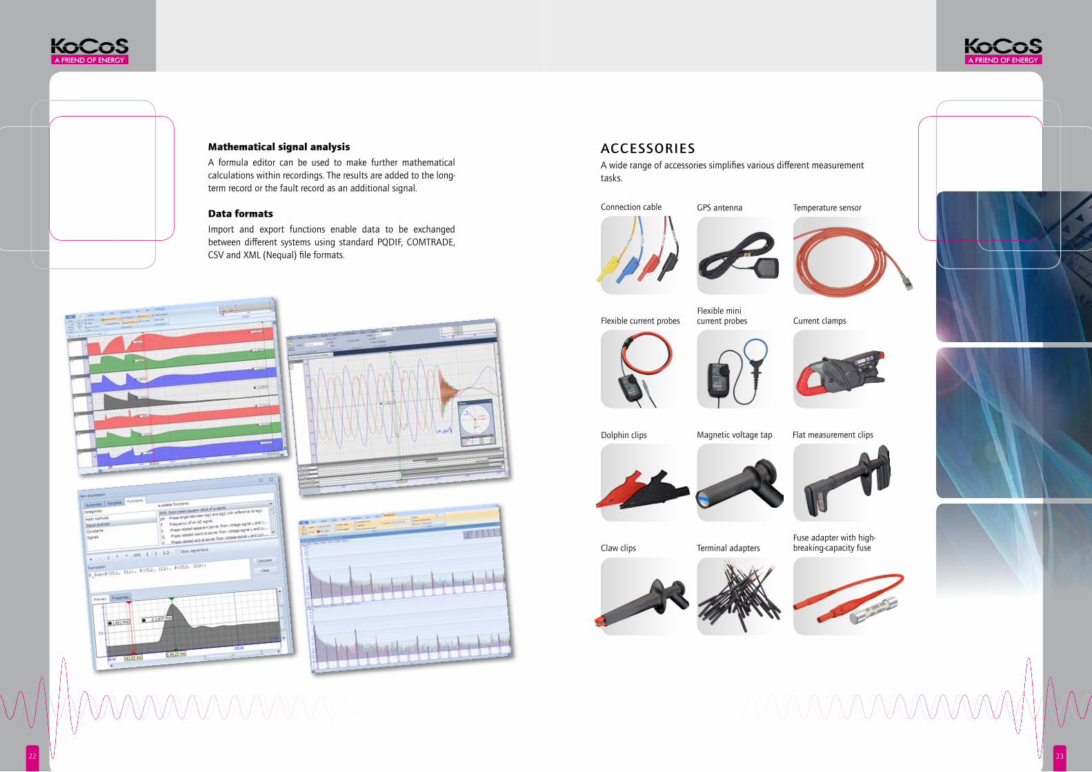
Mathematical signal analysisA formula editor can be used to make further mathematical calculations within recordings. The results are added to the long-term record or the fault record as an additional signal.
Data formatsImport and export functions enable data to be exchanged between different systems using standard PQDIF, COMTRADE, CSV and XML (Nequal) file formats.
aCCEssorIEsA wide range of accessories simplifies various different measurement tasks.
Connection cable
Flexible current probes
Dolphin clips Magnetic voltage tap
Terminal adapters
Flat measurement clips
Fuse adapter with high-breaking-capacity fuse Claw clips
Flexible minicurrent probes Current clamps
Temperature sensorGPS antenna
2524
PRODUCT OVERVIEW EPPE PX
Article number: power quality analyser EppE pX including software for operation and evaluation 4183
Analog inputs:4 voltage inputs (600 VAC L-N), 4 current inputs (32 AAC), 4 current sensor inputs (3 VAC)Sensor inputs / outputs: 4 sensor inputs (0…10 V), 1 temperature input, 1 process outputPower supply unit: 100...240 VAC (100...350 VDC), 9...18 VDCCommunication interfaces: Ethernet RJ45, USB (active/passive)Time synchronization: Internal real-time clock, GPS and DCF receiver, Interlink interface,8 binary inputs2 relay outputs4 GB data memory7“ colour graphical display with touch screenMeasurements according to IEC 61000-4-30 / EN 50160Connection cable set for voltage inputsConnection cable set for direct inputs for current measurementConnection cable for sensor inputDolphin clips, set of 4 x black / red 10 terminal adaptersGPS antenna with magnetic baseAccessory case, standard
AccessoriesFlexible current probe ACP3000 (switchable 30/300/3000 A) .................................................................................................................4146Flexible current probe ACP300 (switchable 3/30/300 A) ...........................................................................................................................4502Passive AC current clamp 10 A .................................................................................................................................................................................4169Temperature sensor .......................................................................................................................................................................................................4186Extended connection cable set .................................................................................................................................................................................4059Fuse adapter with high-breaking-capacity fuse ...................................................................................................................................................4187Terminal adapter TA, 25 pieces ................................................................................................................................................................................ 1171Set of flat measurement clips, 4 x black ................................................................................................................................................................4192Set of magnetic voltage taps, 4 x black / red .....................................................................................................................................................4188Set of claw clips, 4 x black / red ............................................................................................................................................................................4190Set of dolphin clips, 4 x black / red / yellow / blue ........................................................................................................................................4193
Operating PCsPortable operating PC .................................................................................................................................................................................................6065Stationary operating PC ........................................................................................................................................................................................... 11630
PRODUCT OVERVIEW EPPE CX
Article number: power quality analyser EppE CX ...................................................................................................................................... 4224
softwareProfessional EPPE software .................................................................................................................................................... 4152Premium EPPE software .......................................................................................................................................................... 4151
accessoriesGPS receiver module ............................................................................................................................................................... 4060 GPS antenna with magnetic base ....................................................................................................................................... 11679GPS antenna for installation on a building with surge protector and antenna lead ........................................ 11558Wall mount ................................................................................................................................................................................ 4218
operating pCsPortable operating PC ............................................................................................................................................................. 6065Stationary operating PC ......................................................................................................................................................... 11630Stationary operating PC for 19“ rack mounting ............................................................................................................. 6932
Server (tower) ............................................................................................................................................................................ 4179Server (rack) for 19“ rack mounting .................................................................................................................................... 4178
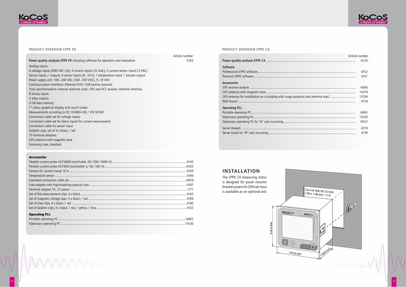
Install atIon The EPPE CX measuring instrument is designed for panel mounting. A bracket system for DIN-rail mounting is available as an optional extra.
2726
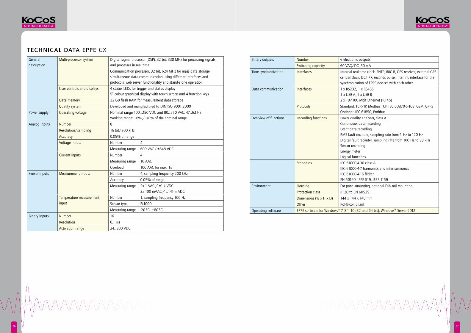
General description
Multi-processor system Digital signal processor (DSP), 32 bit, 330 MHz for processing signals and processes in real time
Communication processor, 32 bit, 624 MHz for mass data storage, simultaneous data communication using different interfaces and protocols, web server functionality and stand-alone operation
User controls and displays 4 status LEDs for trigger and status display 5“ colour graphical display with touch screen and 4 function keys
Data memory 32 GB flash RAM for measurement data storage
Quality system Developed and manufactured to DIN ISO 9001:2000
Power supply Operating voltage Nominal range 100...250 VDC and 90...250 VAC; 47...63 HzWorking range: +6% / -10% of the nominal range
Analog inputs
Number 8
Resolution/sampling 16 bit/200 kHz
Accuracy 0.05% of range
Voltage inputs Number 4
Measuring range 600 VAC / ±848 VDC
Current inputs Number 4
Measuring range 10 AAC
Overload 100 AAC for max. 1s
Sensor inputs Measurement inputs Number 4, sampling frequency 200 kHz
Accuracy 0.05% of range
Measuring range 2x 1 VAC / ±1.4 VDC 2x 100 mAAC / ±141 mADC
Temperature measurement input
Number 1, sampling frequency 100 Hz
Sensor type Pt1000
Measuring range -20°C...+80°C
Binary inputs Number 16
Resolution 0.1 ms
Activation range 24…300 VDC
tEChnICal data EppE CXBinary outputs Number 6 electronic outputs
Switching capacity 60 VAC/DC, 50 mA
Time synchronization Interfaces Internal real-time clock, SNTP, IRIG-B, GPS receiver, external GPS central clock, DCF 77, seconds pulse, Interlink interface for the synchronization of EPPE devices with each other
Data communication Interfaces 1 x RS232, 1 x RS485 1 x USB-A, 1 x USB-B2 x 10/100 Mbit Ethernet (RJ 45)
Protocols Standard: TCP/IP, Modbus TCP, IEC 60870-5-103, GSM, GPRSOptional: IEC 61850, Profibus
Overview of functions Recording functions Power quality analyser, class AContinuous data recordingEvent data recordingRMS fault recorder, sampling rate from 1 Hz to 120 HzDigital fault recorder, sampling rate from 100 Hz to 30 kHzSensor recordingEnergy meterLogical functions
Standards IEC 61000-4-30 class AIEC 61000-4-7 harmonics and interharmonicsIEC 61000-4-15 flickerEN 50160, IEEE 519, IEEE 1159
Environment Housing For panel-mounting, optional DIN-rail mounting
Protection class IP 20 to EN 60529
Dimensions (W x H x D) 144 x 144 x 140 mm
Other RoHS-compliant
Operating software EPPE software for Windows® 7, 8.1, 10 (32 and 64 bit), Windows® Server 2012
2928
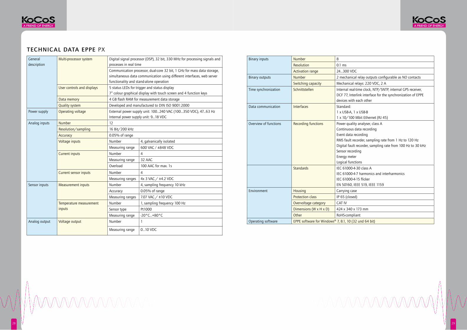
tEChnICal data EppE PXGeneraldescription
Multi-processor system Digital signal processor (DSP), 32 bit, 330 MHz for processing signals and processes in real time
Communication processor, dual-core 32 bit, 1 GHz for mass data storage, simultaneous data communication using different interfaces, web server functionality and stand-alone operation
User controls and displays 5 status LEDs for trigger and status display 7“ colour graphical display with touch screen and 4 function keys
Data memory 4 GB flash RAM for measurement data storage
Quality system Developed and manufactured to DIN ISO 9001:2000
Power supply Operating voltage External power supply unit: 100...240 VAC (100...350 VDC), 47...63 HzInternal power supply unit: 9…18 VDC
Analog inputs Number 12
Resolution/sampling 16 Bit/200 kHz
Accuracy 0.05% of range
Voltage inputs Number 4, galvanically isolated
Measuring range 600 VAC / ±848 VDC
Current inputs Number 4
Measuring range 32 AAC
Overload 100 AAC for max. 1s
Current sensor inputs Number 4
Measuring ranges 4x 3 VAC / ±4.2 VDC
Sensor inputs Measurement inputs Number 4, sampling frequency 10 kHz
Accuracy 0.05% of range
Measuring ranges 7.07 VAC / ±10 VDC
Temperature measurement inputs
Number 1, sampling frequency 100 Hz
Sensor type Pt1000
Measuring range -20°C...+80°C
Analog output Voltage output Number 1
Measuring range 0…10 VDC
Binary inputs Number 8
Resolution 0.1 ms
Activation range 24…300 VDC
Binary outputs Number 2 mechanical relay outputs configurable as NO contacts
Switching capacity Mechanical relays: 220 VDC, 2 A
Time synchronization Schnittstellen Internal real-time clock, NTP/SNTP, internal GPS receiver, DCF 77, Interlink interface for the synchronization of EPPE devices with each other
Data communication Interfaces Standard:1 x USB-A, 1 x USB-B1 x 10/100 Mbit Ethernet (RJ 45)
Overview of functions Recording functions Power quality analyser, class AContinuous data recordingEvent data recordingRMS fault recorder, sampling rate from 1 Hz to 120 HzDigital fault recorder, sampling rate from 100 Hz to 30 kHzSensor recordingEnergy meterLogical functions
Standards IEC 61000-4-30 class AIEC 61000-4-7 harmonics and interharmonicsIEC 61000-4-15 flickerEN 50160, IEEE 519, IEEE 1159
Environment Housing Carrying case
Protection class IP 65 (closed)
Overvoltage category CAT IV
Dimensions (W x H x D) 424 x 340 x 173 mm
Other RoHS-compliant
Operating software EPPE software for Windows® 7, 8.1, 10 (32 und 64 bit)

3130
PE N L1 L2 L3
GPS/DCF
Ethernet
Power supply I1, I2, I3, IN
U1, U2, U3, U (EN)
Binary signals
EN 50160 - Analysis of voltage, current, power (energy)
U1, U2, U3, U (EN)
I1, I2, I3, IN
DC current
DC voltage
DC current
Humidity sensor
DC voltage
Light irradiation
Outside temperature
Module temperature
Sensor inputs
GPS/DCF
Power supply
Ethernet
=Inverter
Power utilitiy
Consumer
I1, I2, I3, IN
U1, U2, U3, U (EN)
Binary signals
PV plant
EX amplEs oF applICatIons EppE CX | PX
Differential current measurement including voltage analysis
Wind power plant
Temperature
PE N L1 L2 L3
GPS
Ethernet
Power supply
U1, U2, U3, U (EN)
I1, I2, I3, IN
I (PE)
Sensor inputs
Binary signals
GPS/DCF
Power supply
UMTS router
U1, U2, U3, U (EN)
I1, I2, I3, IN
Wind intensity
Wind direction
Acoustic noise
Rotor oscillation
Temperature
Sensor inputs
Mobile network
Internet
Binary signals