Electronic Supplementary Information (ESI)
Enhanced Synergistic Catalysis by Novel Triple-phase Interfaces Design of
NiO/Ru@Ni for Hydrogen Evolution Reaction
Chenglin Zhong,‡a Qingwen Zhou,‡a Shengwen Li,a Lin Cao,a Jiachen Li,b Zihan Shen,a Haixia Ma,b Jianguo Liu,a
Minghui Lua and Huigang Zhang*a
aNational Laboratory of Solid State Microstructures, College of Engineering and Applied Sciences, and Collaborative
Innovation Center of Advanced Microstructures, Nanjing University, Nanjing 210093, P.R. China.
*E-mail:[email protected]
bDepartment of Chemical Engineering, Northwest University, Xi’an 710069, P. R. China
Fig. S1 SEM images of PNS.
Electronic Supplementary Material (ESI) for Journal of Materials Chemistry A.This journal is © The Royal Society of Chemistry 2019
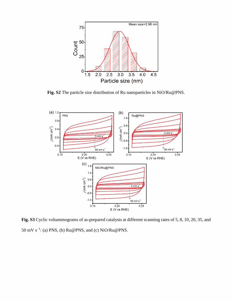
Fig. S2 The particle size distribution of Ru nanoparticles in NiO/Ru@PNS.
Fig. S3 Cyclic voltammograms of as-prepared catalysts at different scanning rates of 5, 8, 10, 20, 35, and
50 mV s−1: (a) PNS, (b) Ru@PNS, and (c) NiO/Ru@PNS.

Fig. S4 TOFs of NiO/Ru@PNS and Ru@PNS at different overpotential.
Fig. S5 Optical photograph shows the bubble generation at −200 mA cm−2.

Fig. S6 (a) SEM image of the NiO/Ru@PNS electrode surface after 80 h electrolysis. (b) TEM image,
(c) HRTEM image, and (d) SAED of the obtained Ru nanoparticles from the NiO/Ru@PNS sample after
the 80 h electrolysis.
Fig. S7 Faradaic efficiency of NiO/Ru@PNS for HER.
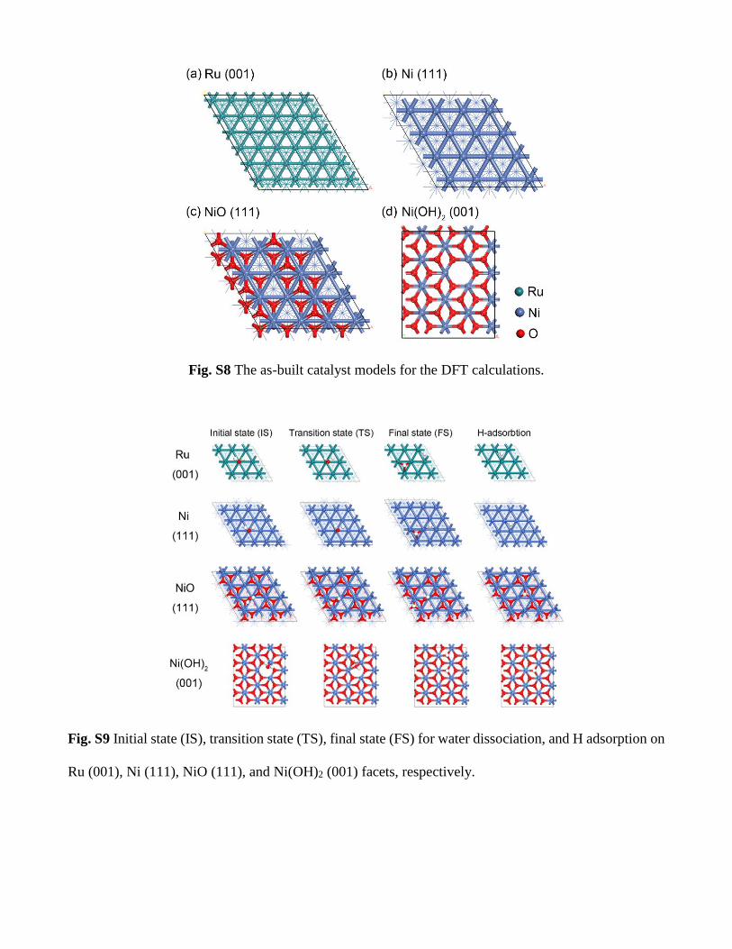
Fig. S8 The as-built catalyst models for the DFT calculations.
Fig. S9 Initial state (IS), transition state (TS), final state (FS) for water dissociation, and H adsorption on
Ru (001), Ni (111), NiO (111), and Ni(OH)2 (001) facets, respectively.
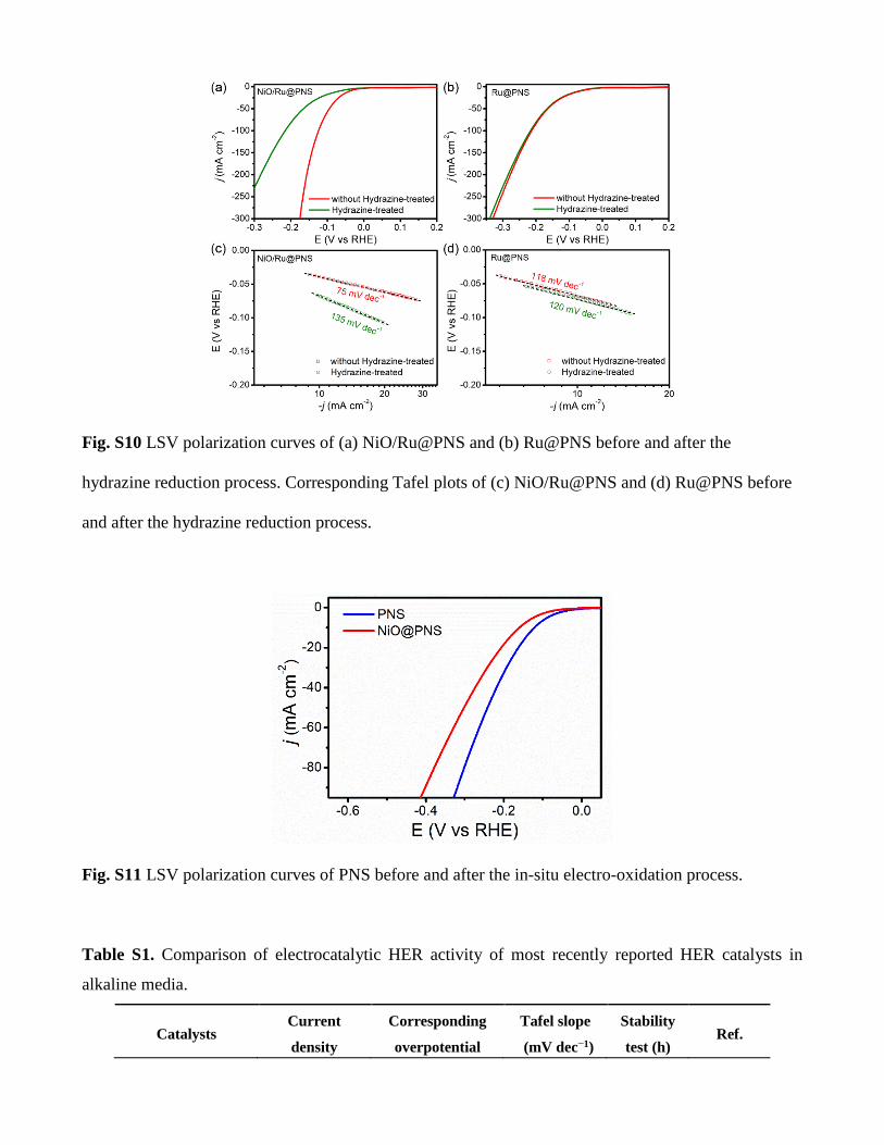
Fig. S10 LSV polarization curves of (a) NiO/Ru@PNS and (b) Ru@PNS before and after the
hydrazine reduction process. Corresponding Tafel plots of (c) NiO/Ru@PNS and (d) Ru@PNS before
and after the hydrazine reduction process.
Fig. S11 LSV polarization curves of PNS before and after the in-situ electro-oxidation process.
Table S1. Comparison of electrocatalytic HER activity of most recently reported HER catalysts in
alkaline media.
Catalysts Current
density
Corresponding
overpotential
Tafel slope
(mV dec−1)
Stability
test (h) Ref.
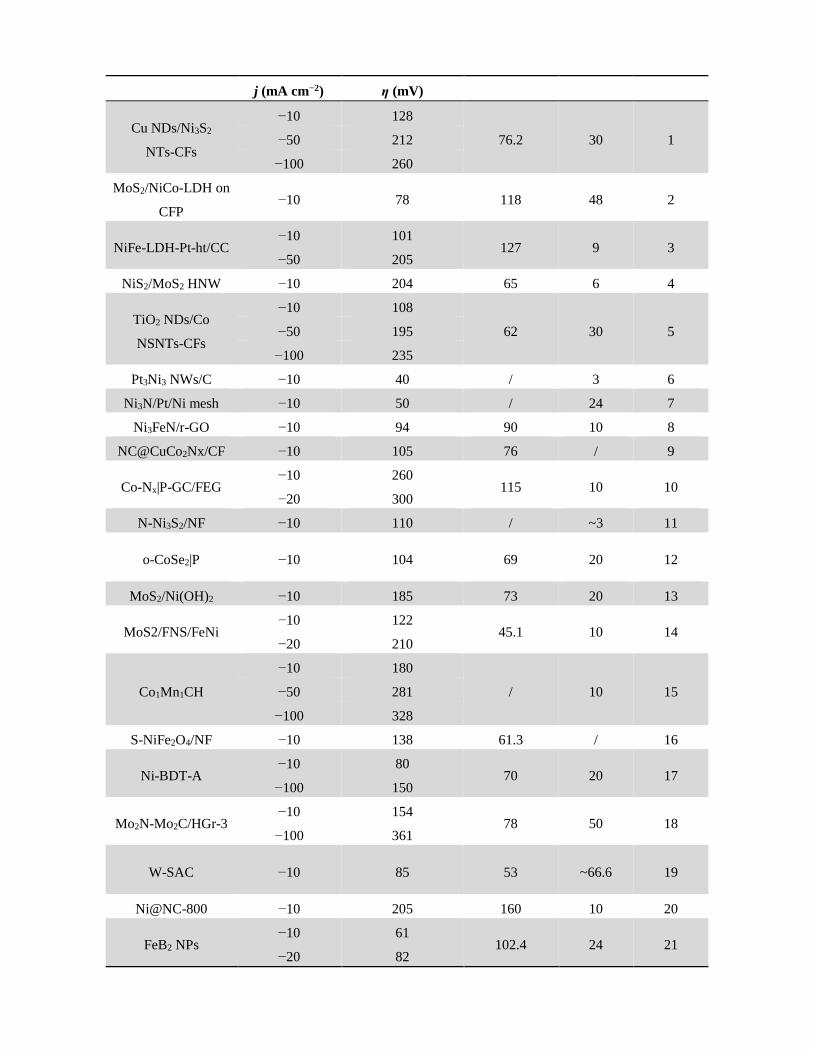
j (mA cm−2) η (mV)
Cu NDs/Ni3S2
NTs-CFs
−10 128
76.2 30 1 −50 212
−100 260
MoS2/NiCo-LDH on
CFP −10 78 118 48 2
NiFe-LDH-Pt-ht/CC −10 101
127 9 3 −50 205
NiS2/MoS2 HNW −10 204 65 6 4
TiO2 NDs/Co
NSNTs-CFs
−10 108
62 30 5 −50 195
−100 235
Pt3Ni3 NWs/C −10 40 / 3 6
Ni3N/Pt/Ni mesh −10 50 / 24 7
Ni3FeN/r-GO −10 94 90 10 8
NC@CuCo2Nx/CF −10 105 76 / 9
Co-Nx|P-GC/FEG −10 260
115 10 10 −20 300
N-Ni3S2/NF −10 110 / ~3 11
o-CoSe2|P −10 104 69 20 12
MoS2/Ni(OH)2 −10 185 73 20 13
MoS2/FNS/FeNi −10 122
45.1 10 14 −20 210
Co1Mn1CH
−10 180
/ 10 15 −50 281
−100 328
S-NiFe2O4/NF −10 138 61.3 / 16
Ni-BDT-A −10 80
70 20 17 −100 150
Mo2N-Mo2C/HGr3 −10 154
78 50 18 −100 361
W-SAC −10 85 53 ~66.6 19
Ni@NC-800 −10 205 160 10 20
FeB2 NPs −10 61
102.4 24 21 −20 82

−100 172
NFN-MOF/NF −10 87 35.2 30 22
NiFeSP/NF −10 94
82.6 25 23 −50 150
Ni(OH)2@CuS −10 150 24.2 24 24
NiO/Ru@PNS
−10 39
75 80 This
work
−50 94
−100 124
−200 157
Supplemental Information Note S1: Calculation of double-layer capacitance (Cdl).
The Cdl was used to determine the electrochemically active surface area (ECSA) of each electrode
according to the reference.25 To measure the value of Cdl, the potential was swept between 0.157 and
0.257 V versus the reversible hydrogen electrode (RHE) at varied scan rates. A potential range of
0.157~0.257 V was selected for the capacitance measurements because no obvious faradaic reactions can
be observed in this region. The capacitive currents of ΔJ׀Ja-Jc0.207@׀ V/2 are plotted with respect to the
cyclic voltammetry (CV) scan rates. The data are fitted to a line, whose slope is the Cdl. The Cdl is
proportional to the surface area of electrode.
The ECSA of a catalyst can be calculated from the Cdl according equation S1:2–4
ECSA = CdlCs
(S1)
where Cs is the capacitance of the sample of an atomically smooth planar surface of material per unit
area under identical electrolyte conditions. Here we use general specific capacitance of Cs=0.04 mF cm−2
in 1 M KOH based on typical reported values.26,27

Supplemental Information Note S2: Calculation of turn over frequency (TOF).
The TOF values can be calculated by the equation TOF = I/2nF, where these physical variables F, n,
and I are corresponding to the Faraday constant (~96485 C/mol), the number of active sites (mol), and
the current (A) during the LSV measurement in 1 M KOH, respectively. The factor 1/2 is due to fact that
two electrons are required to form one hydrogen molecule from two protons.
The number of active sites was determined by an electrochemical method.28-31 The CV curves were
carried out in the potential range of -0.2–0.6 V vs RHE with a scan rate of 50 mV s–1 in 1M PBS
electrolyte (pH = 7). Due to the difficulty in assigning the observed peaks to a given redox couple, the
number of active sites is nearly proportional to the integrated voltammetric charges (cathodic and anodic)
over the CV curves. Supposing a one electron process for both reduction and oxidation, we can get the
upper limit of the number of active sites (n) based on the equation n = Q/2F, where F and Q are the
Faraday constant and the whole charge of CV curve, respectively. The resulting value is the number of
active sites of the catalyst.
Supplemental Information Note S3: H2 quantification and Faraday efficiency.
Faraday efficiencies of the HER were calculated by the ratio of the actual amount of evolved H2 to the
theoretical amount of H2.32,33 H2 was collected by a water drainage method and its amount (in mol) was
then calculated using the ideal gas law.34,35 The theoretical H2 amount is determined by assuming that
100% electrolysis efficiency. Fig. S6 shows the experimental and theoretical amounts of H2 after 90 min
electrolysis.
Supplemental Information Note S4: The density functional theory (DFT) Computational details.
The DFT studies were performed by using the Vienna Ab initio Simulation Package (VASP)36,37
along with the projector augmented wave (PAW)38 method. The generalized gradient approximation
(GGA)39 functional with the Perdew-Burke-Emzerhof formulation was adopted to describe the exchange-
correlation interaction among electrons, and we used an energy cutoff of 450 eV for the plane wave
expansion. A semi-empirical van der waals (vdW)40,41 correction (optB86b-vdW) for the dispersion
interactions was considered. More than 10 Å thick slabs with 16 Å of vacuum along the z-direction were
used to model for calculation of the surface so that these systems were large enough to avoid artificial
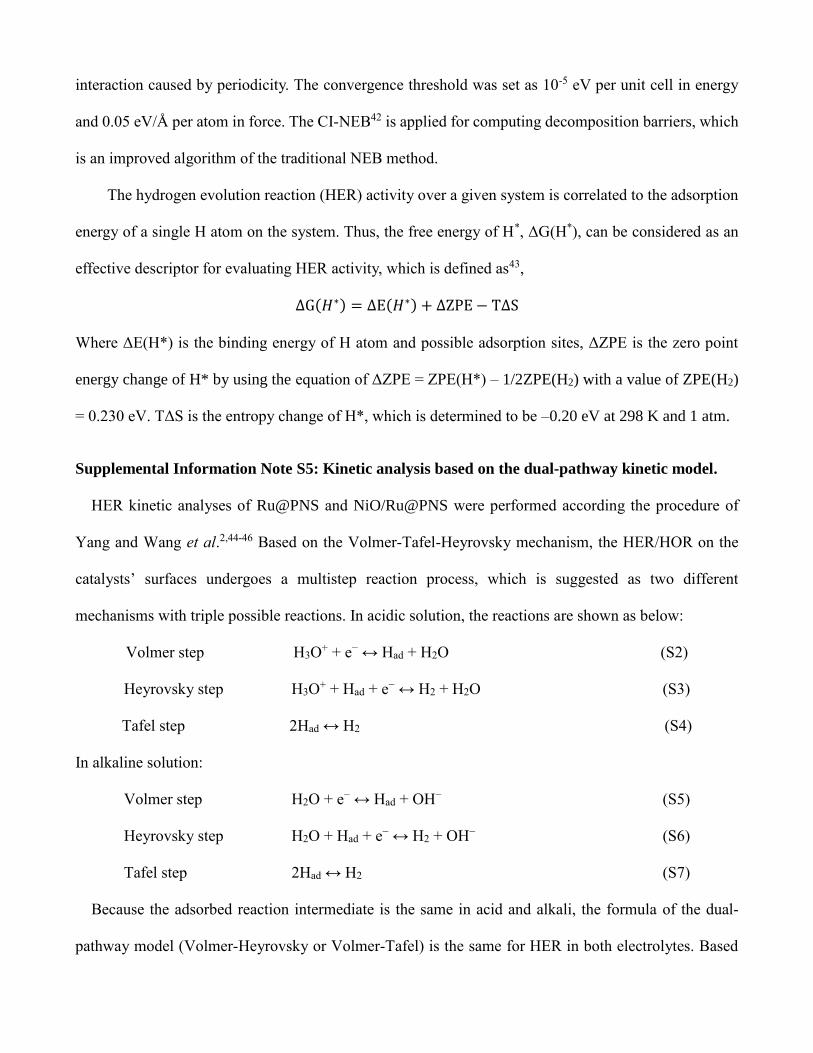
interaction caused by periodicity. The convergence threshold was set as 10-5 eV per unit cell in energy
and 0.05 eV/Å per atom in force. The CI-NEB42 is applied for computing decomposition barriers, which
is an improved algorithm of the traditional NEB method.
The hydrogen evolution reaction (HER) activity over a given system is correlated to the adsorption
energy of a single H atom on the system. Thus, the free energy of H*, ΔG(H*), can be considered as an
effective descriptor for evaluating HER activity, which is defined as43,
∆G(𝐻∗) = ∆E(𝐻∗) + ∆ZPE − T∆S
Where ΔE(H*) is the binding energy of H atom and possible adsorption sites, ΔZPE is the zero point
energy change of H* by using the equation of ΔZPE = ZPE(H*) – 1/2ZPE(H2) with a value of ZPE(H2)
= 0.230 eV. TΔS is the entropy change of H*, which is determined to be –0.20 eV at 298 K and 1 atm.
Supplemental Information Note S5: Kinetic analysis based on the dual-pathway kinetic model.
HER kinetic analyses of Ru@PNS and NiO/Ru@PNS were performed according the procedure of
Yang and Wang et al.2,44-46 Based on the Volmer-Tafel-Heyrovsky mechanism, the HER/HOR on the
catalysts’ surfaces undergoes a multistep reaction process, which is suggested as two different
mechanisms with triple possible reactions. In acidic solution, the reactions are shown as below:
Volmer step H3O+ + e− ↔ Had + H2O (S2)
Heyrovsky step H3O+ + Had + e− ↔ H2 + H2O (S3)
Tafel step 2Had ↔ H2 (S4)
In alkaline solution:
Volmer step H2O + e− ↔ Had + OH− (S5)
Heyrovsky step H2O + Had + e− ↔ H2 + OH− (S6)
Tafel step 2Had ↔ H2 (S7)
Because the adsorbed reaction intermediate is the same in acid and alkali, the formula of the dual-
pathway model (Volmer-Heyrovsky or Volmer-Tafel) is the same for HER in both electrolytes. Based
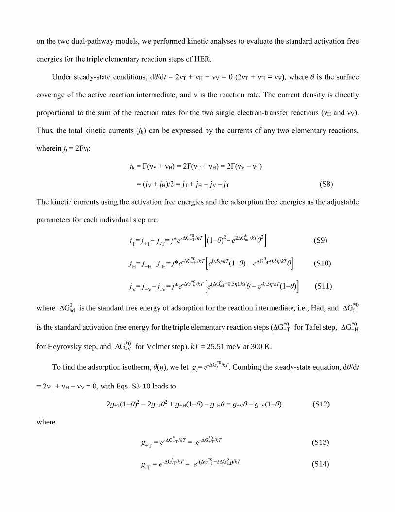
on the two dual-pathway models, we performed kinetic analyses to evaluate the standard activation free
energies for the triple elementary reaction steps of HER.
Under steady-state conditions, dθ/dt = 2νT + νH − νV = 0 (2νT + νH = νV), where θ is the surface
coverage of the active reaction intermediate, and ν is the reaction rate. The current density is directly
proportional to the sum of the reaction rates for the two single electron-transfer reactions (νH and νV).
Thus, the total kinetic currents (jk) can be expressed by the currents of any two elementary reactions,
wherein ji = 2Fνi:
jk = F(νV + νH) = 2F(νT + νH) = 2F(νV – νT)
= (jV + jH)/2 = jT + jH = jV – jT (S8)
The kinetic currents using the activation free energies and the adsorption free energies as the adjustable
parameters for each individual step are:
jT= j
+T– j
-T= j*e-∆G+T
*0/kT [(1–θ)
2– e2∆Gad0
/kTθ2] (S9)
jH
= j+H
– j-H
= j*e-∆G+H*0
/kT [e0.5η/kT(1–θ) – e∆Gad0
-0.5η/kTθ] (S10)
jV
= j+V
– j-V
= j*e-∆G-V*0
/kT [e(∆Gad0
+0.5η)/kTθ – e-0.5η/kT(1–θ)] (S11)
where ∆Gad0
is the standard free energy of adsorption for the reaction intermediate, i.e., Had, and ∆Gi*0
is the standard activation free energy for the triple elementary reaction steps (∆G+T*0
for Tafel step, ∆G+H*0
for Heyrovsky step, and ∆G-V*0
for Volmer step). kT = 25.51 meV at 300 K.
To find the adsorption isotherm, θ(η), we let gi= e-∆Gi
*0/kT. Combing the steady-state equation, dθ/dt
= 2νT + νH − νV = 0, with Eqs. S8-10 leads to
2g+T(1–θ)2 – 2g–Tθ2 + g+H(1–θ) – g–Hθ = g+Vθ – g–V(1–θ) (S12)
where
g+T
= e-∆G+T*
/kT = e-∆G+T*0
/kT (S13)
g-T
= e-∆G-T*
/kT = e-(∆G+T*0
+2∆Gad0
)/kT (S14)
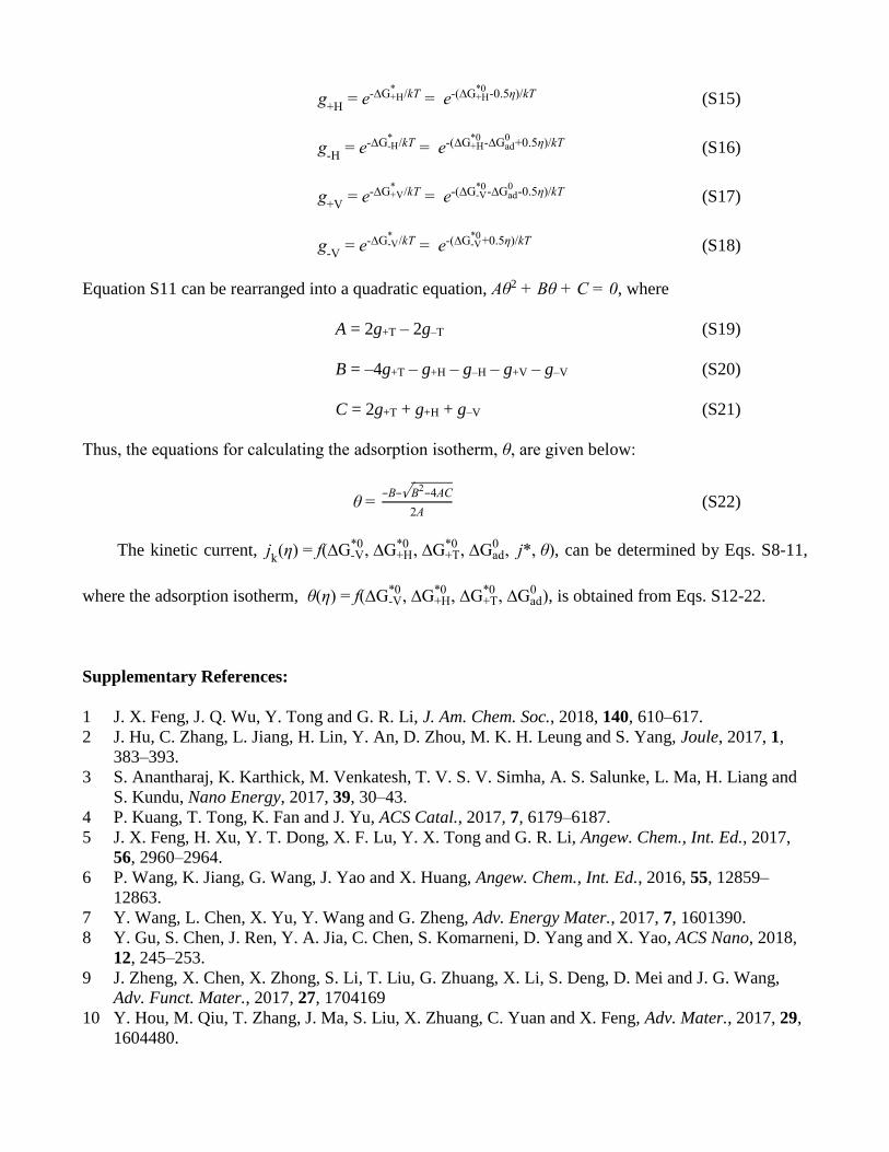
g+H
= e-∆G+H*
/kT = e-(∆G+H*0
-0.5η)/kT (S15)
g-H
= e-∆G-H*
/kT = e-(∆G+H*0
-∆Gad0
+0.5η)/kT (S16)
g+V
= e-∆G+V*
/kT = e-(∆G-V*0
-∆Gad0
-0.5η)/kT (S17)
g-V
= e-∆G-V*
/kT = e-(∆G-V*0
+0.5η)/kT (S18)
Equation S11 can be rearranged into a quadratic equation, Aθ2 + Bθ + C = 0, where
A = 2g+T – 2g–T (S19)
B = –4g+T – g+H – g–H – g+V – g–V (S20)
C = 2g+T + g+H + g–V (S21)
Thus, the equations for calculating the adsorption isotherm, θ, are given below:
θ = –B–√B2–4AC
2A (S22)
The kinetic current, jk(η) = f(∆G-V
*0, ∆G+H
*0, ∆G+T
*0, ∆Gad
0, j*, θ), can be determined by Eqs. S8-11,
where the adsorption isotherm, θ(η) = f(∆G-V*0
, ∆G+H*0
, ∆G+T*0
, ∆Gad0
), is obtained from Eqs. S12-22.
Supplementary References:
1 J. X. Feng, J. Q. Wu, Y. Tong and G. R. Li, J. Am. Chem. Soc., 2018, 140, 610–617.
2 J. Hu, C. Zhang, L. Jiang, H. Lin, Y. An, D. Zhou, M. K. H. Leung and S. Yang, Joule, 2017, 1,
383–393.
3 S. Anantharaj, K. Karthick, M. Venkatesh, T. V. S. V. Simha, A. S. Salunke, L. Ma, H. Liang and
S. Kundu, Nano Energy, 2017, 39, 30–43.
4 P. Kuang, T. Tong, K. Fan and J. Yu, ACS Catal., 2017, 7, 6179–6187.
5 J. X. Feng, H. Xu, Y. T. Dong, X. F. Lu, Y. X. Tong and G. R. Li, Angew. Chem., Int. Ed., 2017,
56, 2960–2964.
6 P. Wang, K. Jiang, G. Wang, J. Yao and X. Huang, Angew. Chem., Int. Ed., 2016, 55, 12859–
12863.
7 Y. Wang, L. Chen, X. Yu, Y. Wang and G. Zheng, Adv. Energy Mater., 2017, 7, 1601390.
8 Y. Gu, S. Chen, J. Ren, Y. A. Jia, C. Chen, S. Komarneni, D. Yang and X. Yao, ACS Nano, 2018,
12, 245–253.
9 J. Zheng, X. Chen, X. Zhong, S. Li, T. Liu, G. Zhuang, X. Li, S. Deng, D. Mei and J. G. Wang,
Adv. Funct. Mater., 2017, 27, 1704169
10 Y. Hou, M. Qiu, T. Zhang, J. Ma, S. Liu, X. Zhuang, C. Yuan and X. Feng, Adv. Mater., 2017, 29,
1604480.
11 P. Chen, T. Zhou, M. Zhang, Y. Tong, C. Zhong, N. Zhang, L. Zhang, C. Wu and Y. Xie, Adv.
Mater., 2017, 29, 1701584.
12 Y. R. Zheng, P. Wu, M. R. Gao, X. L. Zhang, F. Y. Gao, H. X. Ju, R. Wu, Q. Gao, R. You, W. X.
Huang, S. J. Liu, S. W. Hu, J. Zhu, Z. Li and S. H. Yu, Nat. Commun., 2018, 9, 2533.
13 Z. Zhu, H. Yin, C. T. He, M. Al Mamun, P. Liu, L. Jiang, Y. Zhao, Y. Wang, H. G. Yang, Z. Tang,
D. Wang, X. M. Chen and H. Zhao, Adv. Mater., 2018, 1801171.
14 Y. Wu, F. Li, W. Chen, Q. Xiang, Y. Ma, H. Zhu, P. Tao, C. Song, W. Shang, T. Deng and J. Wu,
Adv. Mater., 2018, 30, 1803151.
15 T. Tang, W. J. Jiang, S. Niu, N. Liu, H. Luo, Y. Y. Chen, S. F. Jin, F. Gao, L. J. Wan and J. S. Hu,
J. Am. Chem. Soc., 2017, 139, 8320–8328.
16 J. Liu, D. Zhu, T. Ling, A. Vasileff and S. Z. Qiao, Nano Energy, 2017, 40, 264–273.
17 C. Hu, Q. Ma, S. F. Hung, Z. N. Chen, D. Ou, B. Ren, H. M. Chen, G. Fu and N. Zheng, Chem,
2017, 3, 122–133.
18 H. Yan, Y. Xie, Y. Jiao, A. Wu, C. Tian, X. Zhang, L. Wang and H. Fu, Adv. Mater., 2018, 30,
1704156.
19 W. Chen, J. Pei, C. T. He, J. Wan, H. Ren, Y. Wang, J. Dong, K. Wu, W. C. Cheong, J. Mao, X.
Zheng, W. Yan, Z. Zhuang, C. Chen, Q. Peng, D. Wang and Y. Li, Adv. Mater., 2018, 30,
1800396.
20 Y. Xu, W. Tu, B. Zhang, S. Yin, Y. Huang, M. Kraft and R. Xu, Adv. Mater., 2017, 29, 1605957.
21 H. Li, P. Wen, Q. Li, C. Dun, J. Xing, C. Lu, S. Adhikari, L. Jiang, D. L. Carroll and S. M. Geyer,
Adv. Energy Mater., 2017, 7, 1700513.
22 D. Senthil Raja, X. F. Chuah and S. Y. Lu, Adv. Energy Mater., 2018, 1801065.
23 Y. Xin, X. Kan, L. Y. Gan and Z. Zhang, ACS Nano, 2017, 11, 10303–10312.
24 S. Q. Liu, H. R. Wen, Y. Guo, Y. W. Zhu, X. Z. Fu, R. Sun and C. P. Wong, Nano Energy, 2018,
44, 7–14.
25 Z. L. Wang, X. F. Hao, Z. Jiang, X. P. Sun, D. Xu, J. Wang, H. X. Zhong, F. L. Meng and X. B.
Zhang, J. Am. Chem. Soc., 2015, 137, 15070–15073.
26 C. C. L. McCrory, S. Jung, J. C. Peters and T. F. Jaramillo, J. Am. Chem. Soc., 2013, 135, 16977–
16987.
27 Y. Liu, X. Liang, L. Gu, Y. Zhang, G. D. Li, X. Zou and J. S. Chen, Nat. Commun., 2018, 9, 2609.
28 D. Merki, S. Fierro, H. Vrubel and X. Hu, Chem. Sci., 2011, 2, 1262-1267.
29 J. Tian, Q. Liu, A. M. Asiri and X. P. Sun, J. Am. Chem. Soc., 2014, 136, 7587-7590.
30 X. J. Liu, J. He, S. Z. Zhao, Y. P. Liu, Z. Zhao, J. Luo, G. Z. Hu, X. M. Sun and Y. Ding, Nat. Commun.,
2018, 9, 4365.
31 X. J. Fan, Y. Y. Liu, S. Chen, J. J. Shi, J. J. Wang, A. Fan, W. Y. Zan, S. D. Li, W. A. Goddard and X. M.
Zhang, Nat. Commun., 2018, 9, 1809.
32 Y. Sun, K. Xu, Z. Wei, H. Li, T. Zhang, X. Li, W. Cai, J. Ma, H. J. Fan and Y. Li, Adv. Mater.,
2018, 1802121, 1802121.
33 L. L. Feng, G. Yu, Y. Wu, G. D. Li, H. Li, Y. Sun, T. Asefa, W. Chen and X. Zou, J. Am. Chem.
Soc., 2015, 137, 14023–14026.
34 Y. Liu, Q. Li, R. Si, G. D. Li, W. Li, D. P. Liu, D. Wang, L. Sun, Y. Zhang and X. Zou, Adv.
Mater., 2017, 29, 1606200.
35 H. Xu, J. Cao, C. Shan, B. Wang, P. Xi, W. Liu and Y. Tang, Angew. Chem., Int. Ed., 2018, 57,
8654–8658.
36 G. Kresse and J. Furthmüller, Phys. Rev. B, 1996, 54, 11169.
37 G. Kresse and J. Furthmüller, Comput. Mater. Sci., 1996, 6, 15.
38 G. Kresse and D. Joubert, Phys. Rev. B, 1999, 59, 1758.
39 J. P. Perdew, K. Burke and M. Ernzerhof, Phys. Rev. Lett., 1996, 77, 3865.
40 J. Klime, D. R. Bowler and A. Michaelides, Phys. Rev. B Condens. Matter Mater. Phys., 2011, 83,
195131.
41 J. Klimeš, D. R. Bowler and A. Michaelides, J. Phys. Condens. Matter, 2009, 22, 022201.
42 G. Henkelman, B. P. Uberuaga and H. Jónsson, J. Chem. Phys., 2000, 113, 9901–9904.
43 J. K. Nørskov, T. Bligaard, A. Logadottir, J. R. Kitchin, J. G. Chen, S. Pandelov and U. Stimming,
J. Electrochem. Soc., 2005, 152, J23.
44 K. Elbert, J. Hu, Z. Ma, Y. Zhang, G. Chen, W. An, P. Liu, H. S. Isaacs, R. R. Adzic and J. X.
Wang, ACS Catal., 2015, 5, 6764−6772.
45 J. X. Wang, T. E. Springer and R. R. Adzic, J. Electrochem. Soc., 2006, 153, A1732–A1740.
46 J. X. Wang, T. E. Springer, P. Liu, M. Shao and R. R. Adzic, J. Phys. Chem. C, 2007, 111, 12425–
12433.