INSTRUCTION MANUALMANUAL DE INSTRUCCIONES
MANUEL D’INSTRUCTIONS
52047798 REV 1 © 2014 Greenlee Textron Inc. 3/14
Read and understand all of the instructions and safety information in this manual before operating or servicing this tool.
Lea y entienda todas las instrucciones y la información sobre seguridad que aparecen en este manual, antes de manejar estas herramientas o darles mantenimiento.
Lire attentivement et bien comprendre toutes les instructions et les informations sur la sécurité de ce manuel avant d’utiliser ou de procéder à l’entretien de cet outil.
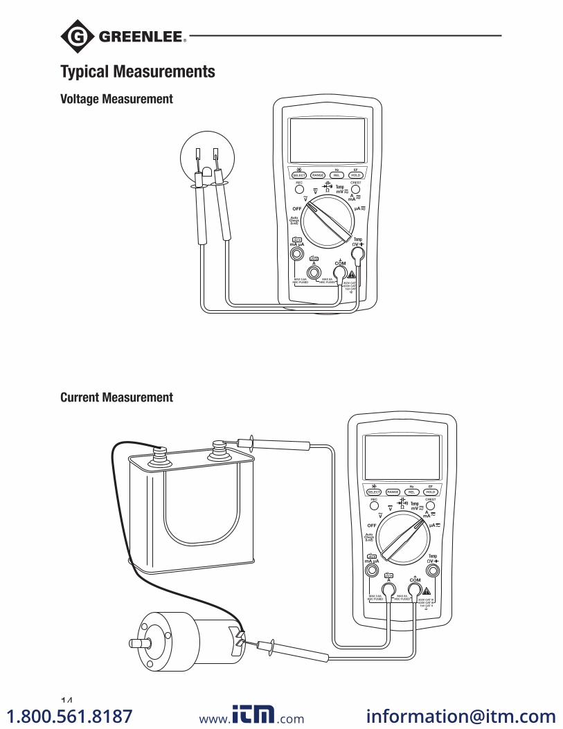
DM-200A • DM-210A DM-510A
Digital Multimeters
Multímetros digitales
Multimètres numériques
www. .com [email protected]
2
Description
The Greenlee DM-200A, DM-210A, and DM-510A Digital Multimeters are hand-held testing devices with the following measurement capabilities: AC and DC voltage, AC and DC current, frequency, and resistance. They also check diodes and verify continuity. An optional optically isolated computer inter-face with software facilitates the recording of readings from the meter to a computer.
Other specialized capabilities and functions common to all meters include:
• Backlighted LCD for reading in dim conditions.
• Beep-Jack™ audible warning alerts the user with a beep and an error message on the LCD if thetest lead is plugged into the mA/μA or A input terminal while the selector switch is not in the mA/μA
or A position.
• Non-contact and single-probe voltage detection capability.
• Bar graph display, which responds more quickly than the numeric display — useful for detectingfaulty contacts, potentiometer clicks, and signal spikes.
• Relative zero mode.
• Data hold mode.
• Selectable automatic power off.
The DM-210A and DM-510A multimeters have the following additional capabilities: temperature (K-type thermocouples only) and capacitance.
The DM-510A multimeter has an AutoCheck™ function for automatic selection of AC voltage, DC voltage, and resistance with low input impedance to mask “ghost” voltages. The DM-510A also has a crest function, which captures voltage or current signal peaks, as well as a recording function, which stores the maximum and minimum input readings. The DM-510A is a true RMS meter.
Safety
Safety is essential in the use and maintenance of Greenlee tools and equipment. This instruction manual and any markings on the tool provide information for avoiding hazards and unsafe practices related to the use of this tool. Observe all of the safety information provided.
Purpose of This Manual
This instruction manual is intended to familiarize all personnel with the safe operation and maintenance procedures for the Greenlee DM-200A, DM-210A, and DM-510A Digital Multimeters
Keep this manual available to all personnel.
Do not discard this product or throw away!
www. .com [email protected]
DM-200A • DM-210A • DM-510A
3
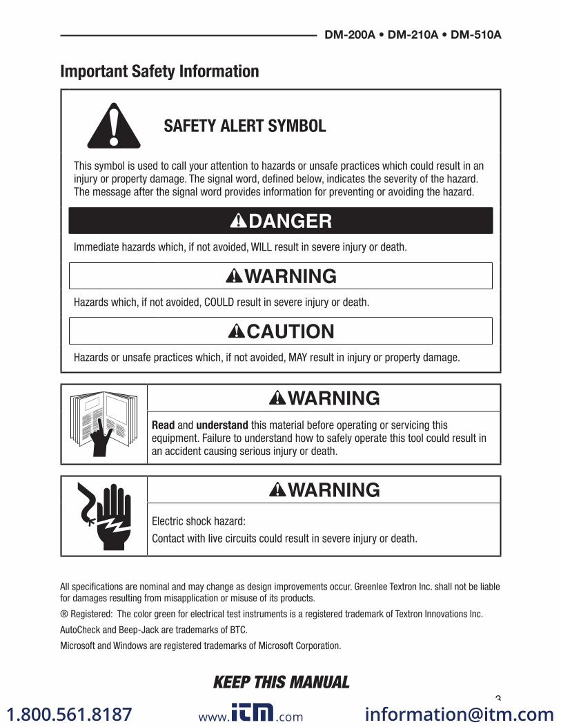
SAFETY ALERT SYMBOL
This symbol is used to call your attention to hazards or unsafe practices which could result in an injury or property damage. The signal word, defined below, indicates the severity of the hazard. The message after the signal word provides information for preventing or avoiding the hazard.
Immediate hazards which, if not avoided, WILL result in severe injury or death.
Hazards which, if not avoided, COULD result in severe injury or death.
Hazards or unsafe practices which, if not avoided, MAY result in injury or property damage.
Read and understand this material before operating or servicing this equipment. Failure to understand how to safely operate this tool could result in an accident causing serious injury or death.
Electric shock hazard:
Contact with live circuits could result in severe injury or death.
Important Safety Information
All specifications are nominal and may change as design improvements occur. Greenlee Textron Inc. shall not be liable for damages resulting from misapplication or misuse of its products.
® Registered: The color green for electrical test instruments is a registered trademark of Textron Innovations Inc.
AutoCheck and Beep-Jack are trademarks of BTC.
Microsoft and Windows are registered trademarks of Microsoft Corporation.
KEEP THIS MANUAL
www. .com [email protected]
4
Important Safety Information
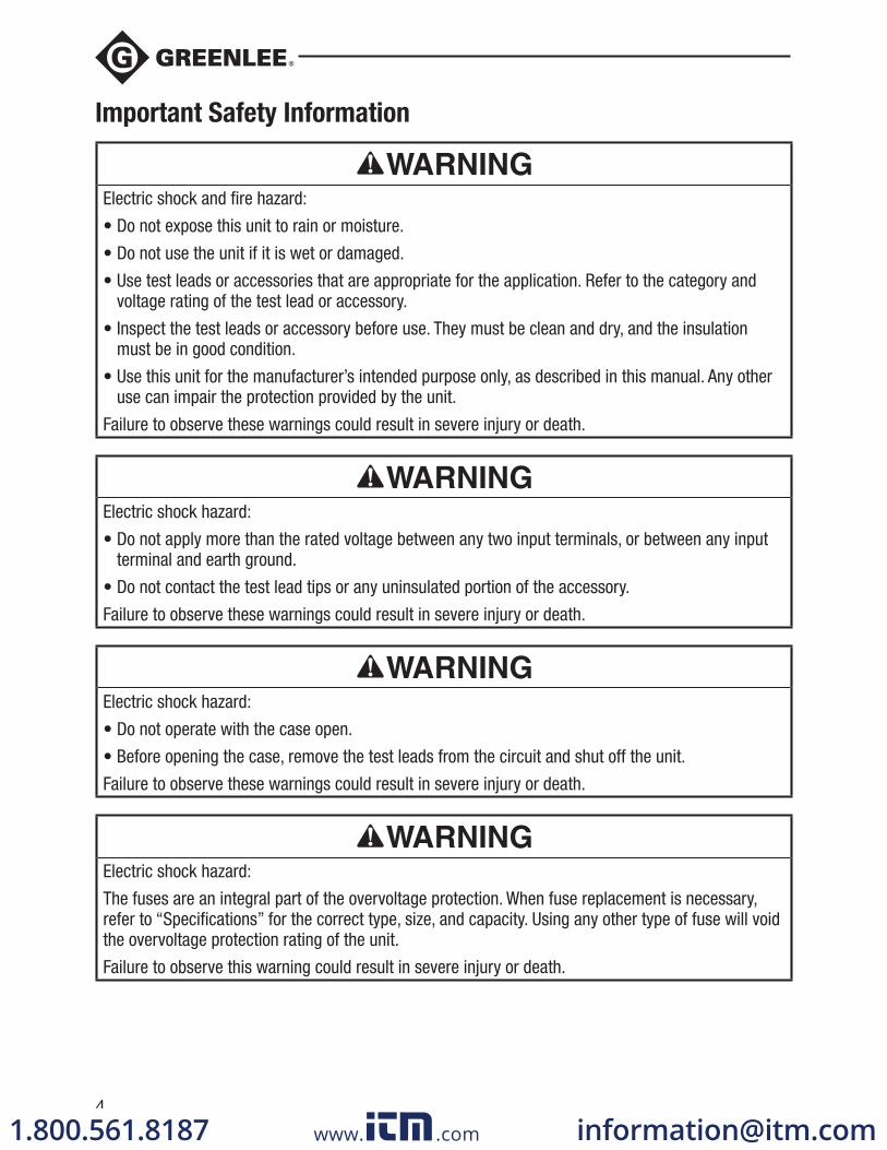
Electric shock and fire hazard:
• Do not expose this unit to rain or moisture.
• Do not use the unit if it is wet or damaged.
• Use test leads or accessories that are appropriate for the application. Refer to the category and voltage rating of the test lead or accessory.
• Inspect the test leads or accessory before use. They must be clean and dry, and the insulation must be in good condition.
• Use this unit for the manufacturer’s intended purpose only, as described in this manual. Any other use can impair the protection provided by the unit.
Failure to observe these warnings could result in severe injury or death.
Electric shock hazard:
• Do not apply more than the rated voltage between any two input terminals, or between any input terminal and earth ground.
• Do not contact the test lead tips or any uninsulated portion of the accessory.
Failure to observe these warnings could result in severe injury or death.
Electric shock hazard:
• Do not operate with the case open.
• Before opening the case, remove the test leads from the circuit and shut off the unit.
Failure to observe these warnings could result in severe injury or death.
Electric shock hazard:
The fuses are an integral part of the overvoltage protection. When fuse replacement is necessary, refer to “Specifications” for the correct type, size, and capacity. Using any other type of fuse will void the overvoltage protection rating of the unit.
Failure to observe this warning could result in severe injury or death.
www. .com [email protected]
DM-200A • DM-210A • DM-510A
5
Important Safety Information
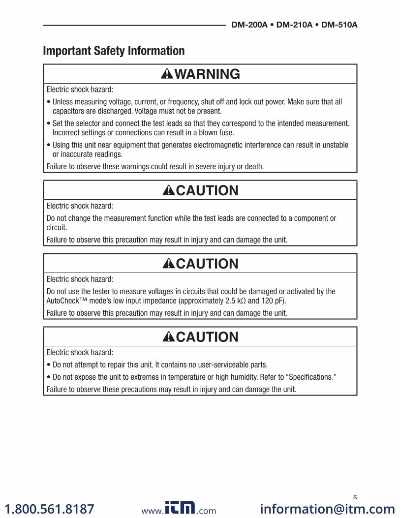
Electric shock hazard:
• Unless measuring voltage, current, or frequency, shut off and lock out power. Make sure that all capacitors are discharged. Voltage must not be present.
• Set the selector and connect the test leads so that they correspond to the intended measurement. Incorrect settings or connections can result in a blown fuse.
• Using this unit near equipment that generates electromagnetic interference can result in unstable or inaccurate readings.
Failure to observe these warnings could result in severe injury or death.
Electric shock hazard:
Do not change the measurement function while the test leads are connected to a component or circuit.
Failure to observe this precaution may result in injury and can damage the unit.
Electric shock hazard:
Do not use the tester to measure voltages in circuits that could be damaged or activated by the AutoCheck™ mode’s low input impedance (approximately 2.5 kΩ and 120 pF).
Failure to observe this precaution may result in injury and can damage the unit.
Electric shock hazard:
• Do not attempt to repair this unit. It contains no user-serviceable parts.
• Do not expose the unit to extremes in temperature or high humidity. Refer to “Specifications.”
Failure to observe these precautions may result in injury and can damage the unit.
www. .com [email protected]
6
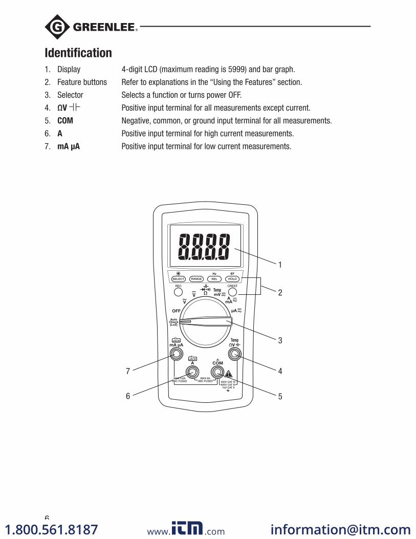
Identification
1. Display 4-digit LCD (maximum reading is 5999) and bar graph.
2. Feature buttons Refer to explanations in the “Using the Features” section.
3. Selector Selects a function or turns power OFF.
4. ΩV Positive input terminal for all measurements except current.
5. COM Negative, common, or ground input terminal for all measurements.
6. A Positive input terminal for high current measurements.
7. mA μA Positive input terminal for low current measurements.
6
7
1
2
4
5
3
www. .com [email protected]
DM-200A • DM-210A • DM-510A
7
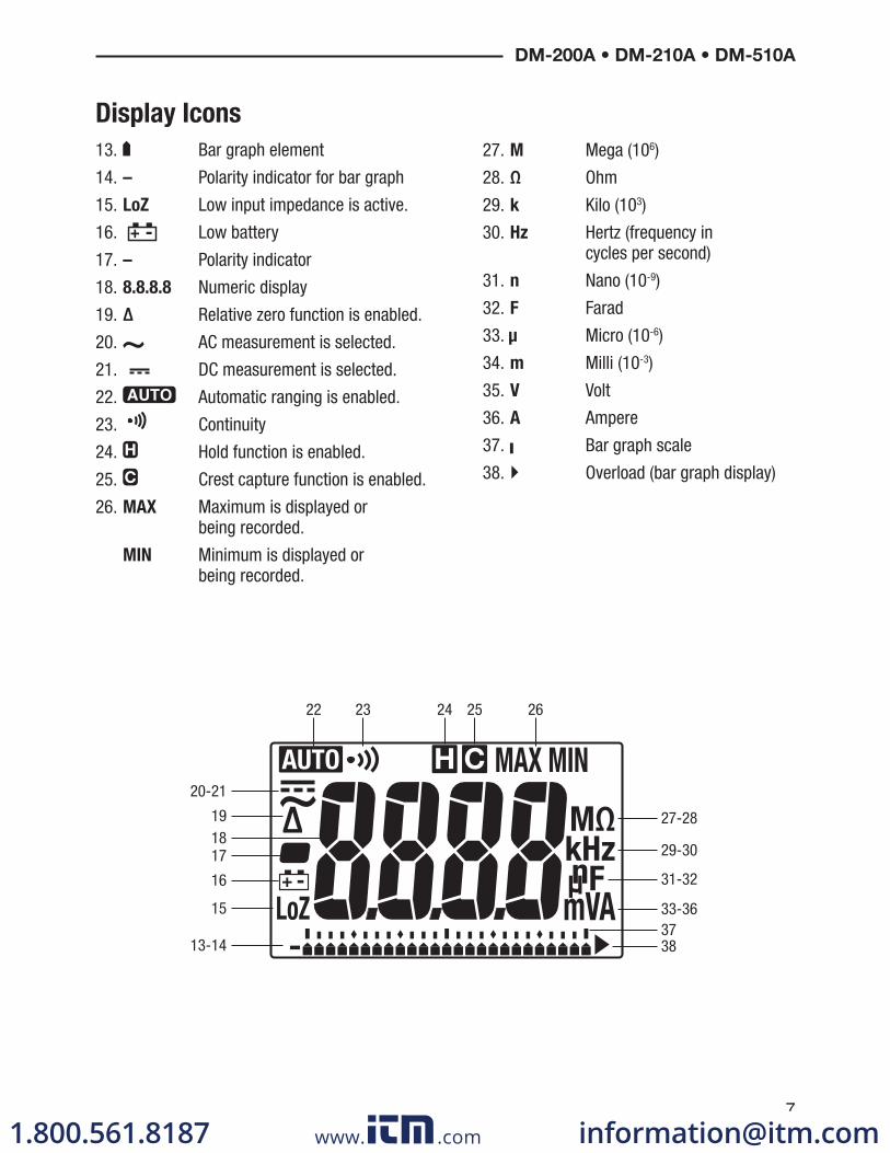
13. Bar graph element
14. – Polarity indicator for bar graph
15. LoZ Low input impedance is active.
16. Low battery
17. – Polarity indicator
18. 8.8.8.8 Numeric display
19. Δ Relative zero function is enabled.
20. AC measurement is selected.
21. DC measurement is selected.
22. Automatic ranging is enabled.
23. Continuity
24. Hold function is enabled.
25. Crest capture function is enabled.
26. MAX Maximum is displayed or being recorded.
MIN Minimum is displayed or being recorded.
27. M Mega (106)
28. Ω Ohm
29. k Kilo (103)
30. Hz Hertz (frequency in cycles per second)
31. n Nano (10-9)
32. F Farad
33. μ Micro (10-6)
34. m Milli (10-3)
35. V Volt
36. A Ampere
37. Bar graph scale
38. Overload (bar graph display)
Display Icons
27-28
29-30
31-32
33-36
3837
19
20-21
16
15
13-14
1718
22 23 24 25 26
www. .com [email protected]
8
Using the Features
All Models
• SELECT: Press momentarily to toggle between functions.
• : Press and hold until backlight illuminates. Press and hold again to turn off. The backlight automatically turns off after approximately 30 seconds to extend battery life.
• RANGE: Press once to enter the manual ranging mode. The icon will disappear from the display. Press repeatedly to step through the ranges. Press and hold to return to the automatic ranging mode.
Note: When using MAX/MIN, HOLD, or Δ mode, pressing RANGE will cause the meter to exit that mode.
• REL: Finds the difference between two measurements. While taking a measurement, press REL to set the display to zero. The Δ icon will appear on the display. Take the second measurement. The value on the display will be the difference between the two measurements. Press again to exit this mode.
• Hz: Press and hold until the meter beeps to enable frequency measurement. The frequency function can be used with the selector in any voltage or current setting. Use the V or A settings for measuring the frequency of sinusoidal waveforms. Use the mV setting for measuring the frequency of 3 volt or 5 volt logic level, square waveform signals.
The sensitivity of the frequency measurement function varies with the measurement range. To automatically select a sensitivity level, measure the voltage or current first, and then press Hz. If the reading becomes unstable or reads zero, press the RANGE button to select a different sensitivity level.
The number of bar graph elements indicates the sensitivity selected:
• 1 element = 6 V, 6 A, 60 mA, or 600 μA
• 2 elements = 60 V, 10 A, 600 mA, or 6000 μA
• 3 elements = 600 V
• 4 elements = 1000 V
• HOLD : Press momentarily to hold the present value on the display. Press again to exit this mode.
This feature does not affect the bar graph.• EF: Set the meter to any current or voltage function. Press and hold until the meter beeps to detect
the electric field that surrounds current-carrying conductors. Signal strength is displayed as a series of dashes on the display.
• Use the tester’s built-in antenna (located along the top, near the LCD) for tracing live circuits or locating a break in a wire.
• For more precision, such as distinguishing between current-carrying and ground wires, connect a test lead to the ΩV input terminal and use it as a probe for direct contact verification of AC voltage.
• Automatic Power Off: To extend battery life, the meter will shut itself off after approximately 30 minutes of inactivity. To restore power, press either the SELECT, CREST, or REC button or turn the selector to OFF and then back on. To disable this feature, press SELECT while turning the meter on.
www. .com [email protected]
DM-200A • DM-210A • DM-510A
9
• Disabling the Beeper: Hold down the RANGE button while turning the meter on to temporarily disable the beeper feature. Turn the selector to OFF and then back on to enable the beeper.
DM-510A Only
• Low Impedance AutoCheck™ Mode: In this mode, the meter automatically selects the proper measurement based on the input.
• If there is no input, “Auto” appears on the display.
• If the voltage is above approximately 1 volt AC or DC, voltage is displayed.
• If both AC and DC voltages are present, the larger voltage is displayed.
• If no voltage is present and there is resistance less than approximately 10 MΩ, resistance is displayed. If the measured resistance is below the continuity threshold (between 10 Ω and 80 Ω), then the continuity tone will sound.
This mode features low input impedance to mask stray or “ghost” voltage pickup. The input imped-ance is approximately 2.5 kΩ at low voltage, increasing to approximately 375 kΩ at 1000 V.
The symbol “LoZ” indicates that the meter is in a low impedance mode. Do not use the AutoCheck™ mode on circuits that could be damaged or activated by such low input impedance. Instead use the selector to select the high impedance AC or DC volts modes to minimize loading for such circuits.
Range-Lock and Function Feature: While in the AutoCheck™ mode, press the SELECT button momentarily to lock the displayed function. Press the RANGE button momentarily to lock the dis-played measurement range. Press either button repeatedly to step through the ranges or functions.
Energized Circuit Alert: If the resistance mode is locked in the AutoCheck™ mode and the leads are placed across an energized circuit, the meter will emit an audible warning tone.
• REC: Press momentarily to activate the MAX/MIN recording mode. The input value is measured every 50 ms in this mode. “MAX MIN” will appear on the display. The LCD will display the actual input value. The meter will beep whenever the maximum or minimum is updated. Press repeatedly to select the desired display: maximum, minimum, or actual input. Press and hold to exit this mode.
The automatic power off feature is disabled when using this function.• CREST: Press momentarily to activate the crest recording mode. The input value is measured every
5 ms in this mode. and “MAX” will appear on the display. The LCD will display the maximum crest value. Press repeatedly to select the desired display: maximum or minimum crest value. Press and hold to exit this mode.
Automatic ranging and automatic power off are disabled when using this function.
Using the Features (cont’d)
www. .com [email protected]
10
AC Measurement
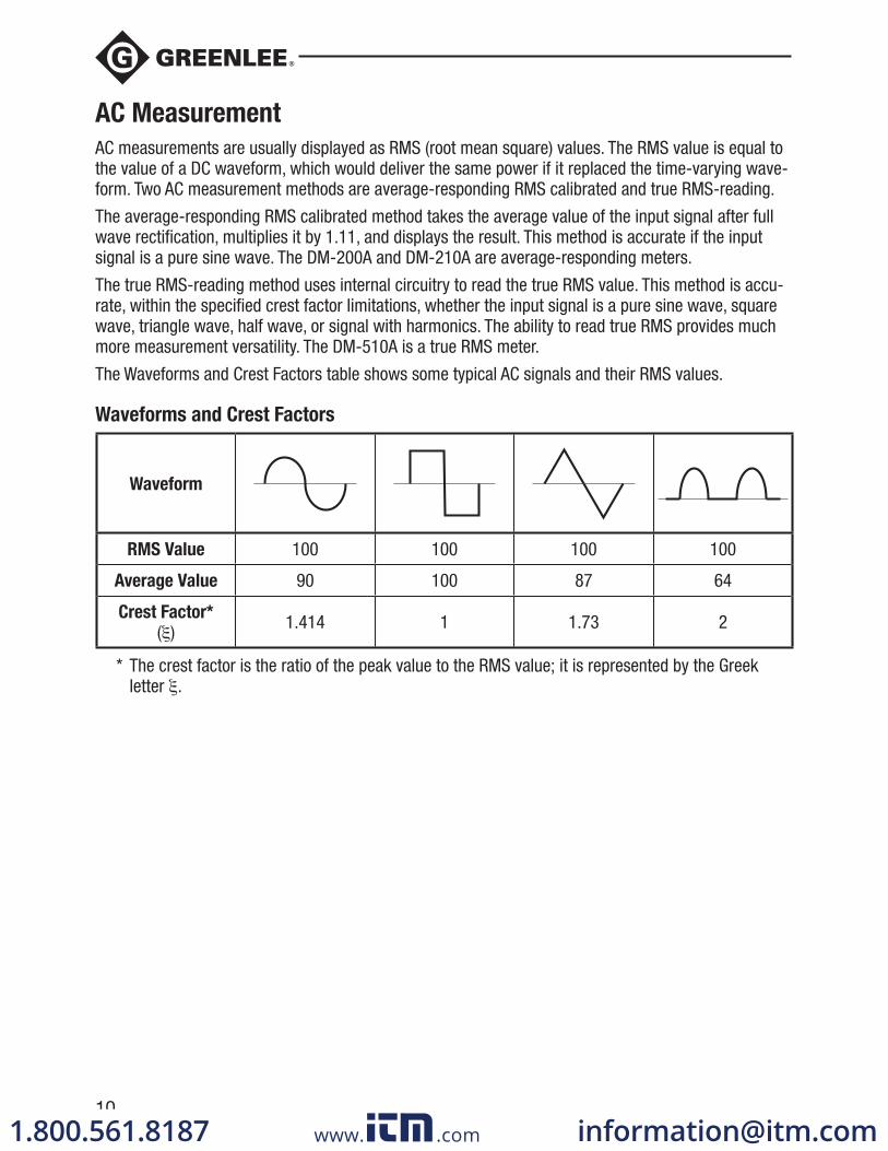
AC measurements are usually displayed as RMS (root mean square) values. The RMS value is equal to the value of a DC waveform, which would deliver the same power if it replaced the time-varying wave-form. Two AC measurement methods are average-responding RMS calibrated and true RMS-reading.
The average-responding RMS calibrated method takes the average value of the input signal after full wave rectification, multiplies it by 1.11, and displays the result. This method is accurate if the input signal is a pure sine wave. The DM-200A and DM-210A are average-responding meters.
The true RMS-reading method uses internal circuitry to read the true RMS value. This method is accu-rate, within the specified crest factor limitations, whether the input signal is a pure sine wave, square wave, triangle wave, half wave, or signal with harmonics. The ability to read true RMS provides much more measurement versatility. The DM-510A is a true RMS meter.
The Waveforms and Crest Factors table shows some typical AC signals and their RMS values.
Waveforms and Crest Factors
Waveform
RMS Value 100 100 100 100
Average Value 90 100 87 64
Crest Factor*
( ) 1.414 1 1.73 2
* The crest factor is the ratio of the peak value to the RMS value; it is represented by the Greek letter .
www. .com [email protected]
DM-200A • DM-210A • DM-510A
11
Using the Optional Software
These meters are compatible with Greenlee DMSC-2U, an optically isolated computer interface cable and software. It allows measurements to be logged to a personal computer using the Microsoft® Windows® operating system.
Installing the Software
1. Insert the CD into the computer’s CDROM drive.
2. The installation program should launch automatically. If it does not, double click on the CD icon in “My Computer.”
3. The installation program menu will appear. Click on “Software Installation.”
4. Type your meter’s catalog number (for example, “DM-510A”) in the dialog box.
5. Complete the remaining dialog boxes according to user preferences.
6. Refer to the program’s Readme file for instructions on using the software.
Connecting the Optical Interface Cable
1. Align the interface with the slot on the back of the meter. The cable must point to the left.
2. Push the interface into the slot.
3. For USB applications, proceed to step 5.
4. For RS-232 applications, connect the interface cable to a serial port on the computer, and proceed to step 8.
5. Connect the interface cable to the RS-232-to-USB adapter supplied with DMSC-2U.
6. Connect the square end of the USB cable to the RS-232-to-USB adapter.
7. Connect the other end of the USB cable to the computer.
8. Press the HOLD button while turning the meter on to enable its communication capabilities.
www. .com [email protected]
12
Operation
Electric shock hazard:
Contact with live circuits could result in severe injury or death.
1. Refer to the Settings Table. Set the selector to the proper setting, press SELECT (when instructed to do so), and connect the test leads to the meter.
2. Refer to “Typical Measurements” for specific measurement instructions.
3. Test the unit on a known functioning circuit or component.
• If the unit does not function as expected on a known functioning circuit, replace the battery and/or fuses.
4. Take the reading from the circuit or component to be tested.
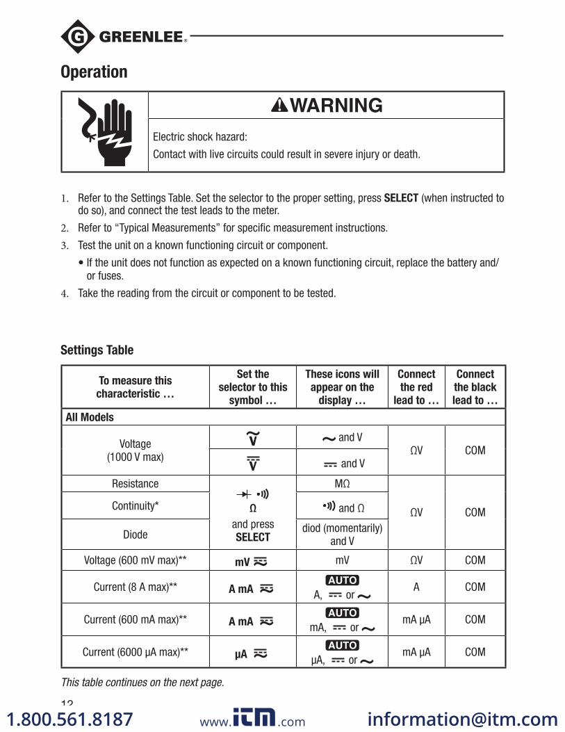
Settings Table
To measure this
characteristic …
Set the
selector to this
symbol …
These icons will
appear on the
display …
Connect
the red
lead to …
Connect
the black
lead to …
All Models
Voltage (1000 V max)
and VΩV COM
and V
Resistance
Ω and press SELECT
MΩ
ΩV COMContinuity* and Ω
Diode diod (momentarily) and V
Voltage (600 mV max)** mV mV ΩV COM
Current (8 A max)** A mA A, or A COM
Current (600 mA max)** A mA mA, or mA μA COM
Current (6000 μA max)** μA μA, or mA μA COM
This table continues on the next page.
www. .com [email protected]

DM-200A • DM-210A • DM-510A
13
Operation (cont’d)Settings Table (cont’d)
To measure this
characteristic …
Set the
selector to this
symbol …
These icons will
appear on the
display …
Connect
the red
lead to …
Connect
the black
lead to …
All Models (cont’d)
Frequency—Line Level Voltage or Current
, A, mA, or μA and press Hz
Hz ΩV COM
Frequency—Logic Level*** mV and press Hz Hz ΩV COM
EF single probe†
Any voltage or current function and press EF for at least 1 second
E.F.ΩV —
EF non-contact† — —
DM-210A and DM-510A Only
Capacitance††
Ω and press SELECT
nFTemp
ΩV COM
Temperature Temp
C or F (press SELECT to
change scale)
Temp ΩV COM
DM-510A Only
Auto select AC volts, DC volts, resistance, and continuity (low
impedance measurement)AutoCheck
and LoZ
Temp ΩV COM
* Tone indicates continuity. The threshold is between 10 Ω and 80 Ω. ** Press SELECT for AC or DC, as required. *** Logic level frequency has a fixed sensitivity and is for digital signals. Refer to “Accuracy”. † Refer to the “Using the Features” section for an explanation of EF (electric field detection). †† Discharge capacitor before measurement. Discharge a large capacitor through an appropriate
resistive load.
www. .com [email protected]
DM-200A • DM-210A • DM-510A
15
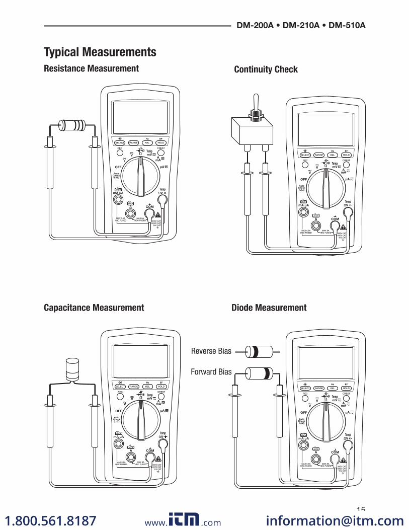
Typical Measurements
Continuity Check
Capacitance Measurement Diode Measurement
Forward Bias
Reverse Bias
Resistance Measurement
www. .com [email protected]
16
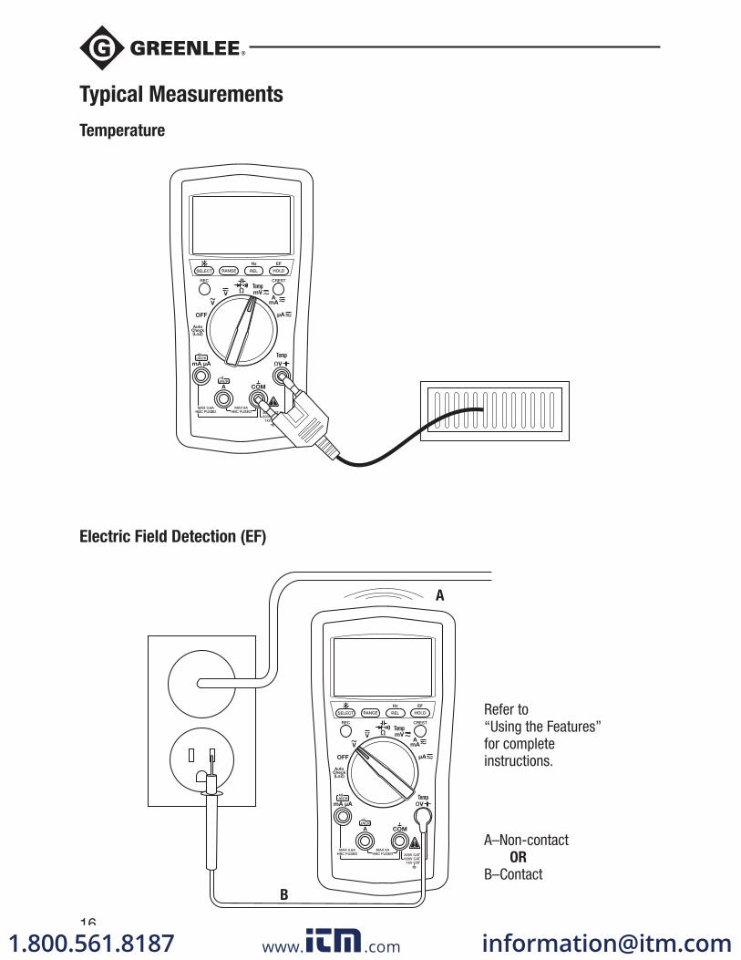
Typical Measurements
Temperature
Electric Field Detection (EF)
Refer to“Using the Features”for completeinstructions.
A–Non-contact OR
B–Contact
A
B
www. .com [email protected]
DM-200A • DM-210A • DM-510A
17
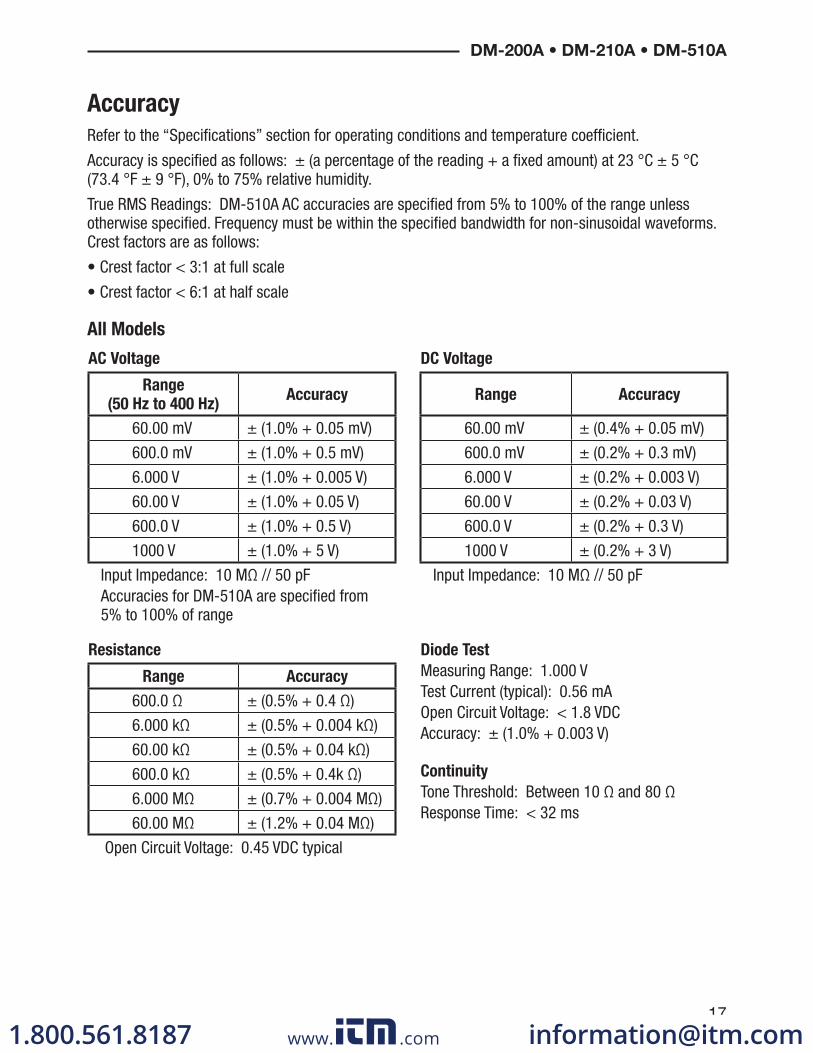
Accuracy
Refer to the “Specifications” section for operating conditions and temperature coefficient.
Accuracy is specified as follows: ± (a percentage of the reading + a fixed amount) at 23 °C ± 5 °C (73.4 °F ± 9 °F), 0% to 75% relative humidity.
True RMS Readings: DM-510A AC accuracies are specified from 5% to 100% of the range unless otherwise specified. Frequency must be within the specified bandwidth for non-sinusoidal waveforms. Crest factors are as follows:
• Crest factor < 3:1 at full scale
• Crest factor < 6:1 at half scale
All Models
AC Voltage DC Voltage
Range
(50 Hz to 400 Hz)Accuracy Range Accuracy
60.00 mV ± (1.0% + 0.05 mV) 60.00 mV ± (0.4% + 0.05 mV)
600.0 mV ± (1.0% + 0.5 mV) 600.0 mV ± (0.2% + 0.3 mV)
6.000 V ± (1.0% + 0.005 V) 6.000 V ± (0.2% + 0.003 V)
60.00 V ± (1.0% + 0.05 V) 60.00 V ± (0.2% + 0.03 V)
600.0 V ± (1.0% + 0.5 V) 600.0 V ± (0.2% + 0.3 V)
1000 V ± (1.0% + 5 V) 1000 V ± (0.2% + 3 V)
Input Impedance: 10 MΩ // 50 pF Accuracies for DM-510A are specified from
5% to 100% of range
Input Impedance: 10 MΩ // 50 pF
Resistance Diode Test
Measuring Range: 1.000 VTest Current (typical): 0.56 mAOpen Circuit Voltage: < 1.8 VDCAccuracy: ± (1.0% + 0.003 V)
Continuity
Tone Threshold: Between 10 Ω and 80 ΩResponse Time: < 32 ms
Range Accuracy
600.0 Ω ± (0.5% + 0.4 Ω)
6.000 kΩ ± (0.5% + 0.004 kΩ)
60.00 kΩ ± (0.5% + 0.04 kΩ)
600.0 kΩ ± (0.5% + 0.4k Ω)
6.000 MΩ ± (0.7% + 0.004 MΩ)
60.00 MΩ ± (1.2% + 0.04 MΩ)
Open Circuit Voltage: 0.45 VDC typical
www. .com [email protected]
18
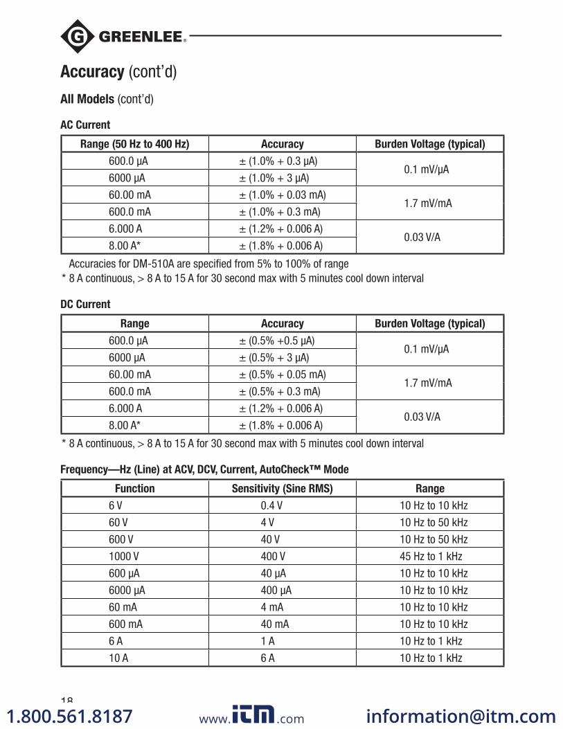
AC Current
Range (50 Hz to 400 Hz) Accuracy Burden Voltage (typical)
600.0 μA ± (1.0% + 0.3 μA)0.1 mV/μA
6000 μA ± (1.0% + 3 μA)
60.00 mA ± (1.0% + 0.03 mA)1.7 mV/mA
600.0 mA ± (1.0% + 0.3 mA)
6.000 A ± (1.2% + 0.006 A)0.03 V/A
8.00 A* ± (1.8% + 0.006 A)
Accuracies for DM-510A are specified from 5% to 100% of range * 8 A continuous, > 8 A to 15 A for 30 second max with 5 minutes cool down interval
DC Current
Range Accuracy Burden Voltage (typical)
600.0 μA ± (0.5% +0.5 μA)0.1 mV/μA
6000 μA ± (0.5% + 3 μA)
60.00 mA ± (0.5% + 0.05 mA)1.7 mV/mA
600.0 mA ± (0.5% + 0.3 mA)
6.000 A ± (1.2% + 0.006 A)0.03 V/A
8.00 A* ± (1.8% + 0.006 A)
* 8 A continuous, > 8 A to 15 A for 30 second max with 5 minutes cool down interval
Frequency —Hz (Line) at ACV, DCV, Current, AutoCheck™ Mode
Function Sensitivity (Sine RMS) Range
6 V 0.4 V 10 Hz to 10 kHz
60 V 4 V 10 Hz to 50 kHz
600 V 40 V 10 Hz to 50 kHz
1000 V 400 V 45 Hz to 1 kHz
600 μA 40 μA 10 Hz to 10 kHz
6000 μA 400 μA 10 Hz to 10 kHz
60 mA 4 mA 10 Hz to 10 kHz
600 mA 40 mA 10 Hz to 10 kHz
6 A 1 A 10 Hz to 1 kHz
10 A 6 A 10 Hz to 1 kHz
Accuracy (cont’d)
All Models (cont’d)
www. .com [email protected]
DM-200A • DM-210A • DM-510A
19
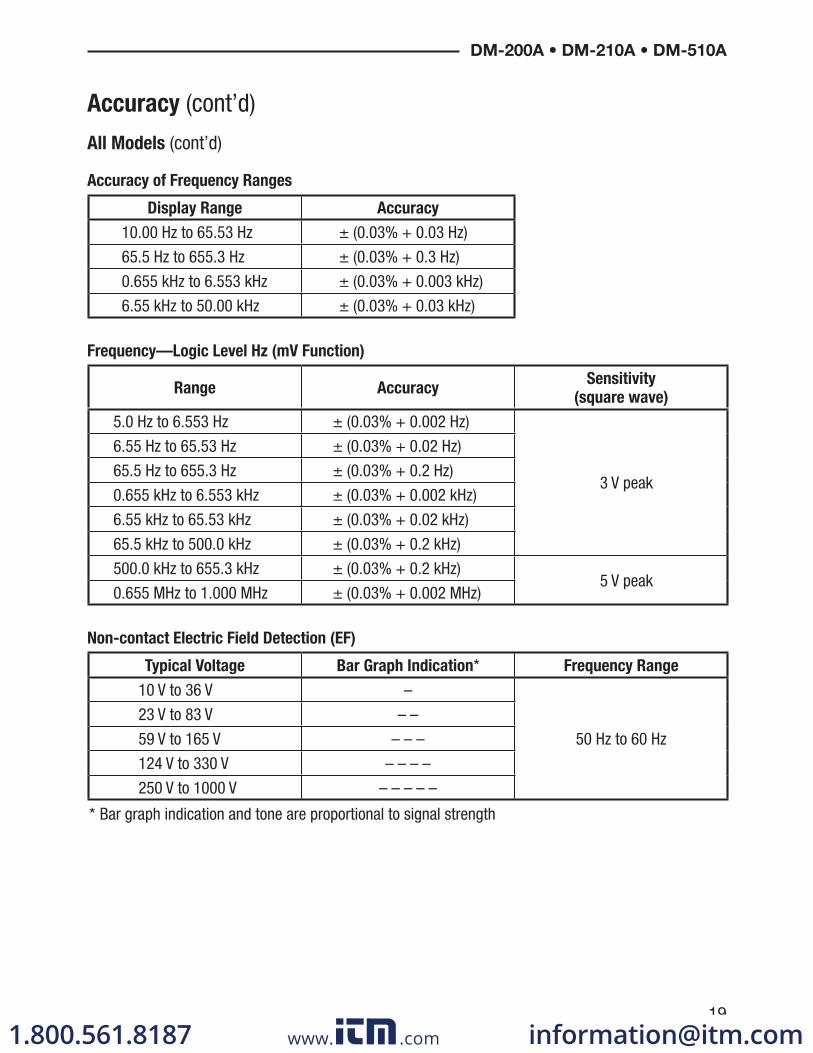
Accuracy (cont’d)
All Models (cont’d)
Accuracy of Frequency Ranges
Display Range Accuracy
10.00 Hz to 65.53 Hz ± (0.03% + 0.03 Hz)
65.5 Hz to 655.3 Hz ± (0.03% + 0.3 Hz)
0.655 kHz to 6.553 kHz ± (0.03% + 0.003 kHz)
6.55 kHz to 50.00 kHz ± (0.03% + 0.03 kHz)
Frequency—Logic Level Hz (mV Function)
Range AccuracySensitivity
(square wave)
5.0 Hz to 6.553 Hz ± (0.03% + 0.002 Hz)
3 V peak
6.55 Hz to 65.53 Hz ± (0.03% + 0.02 Hz)
65.5 Hz to 655.3 Hz ± (0.03% + 0.2 Hz)
0.655 kHz to 6.553 kHz ± (0.03% + 0.002 kHz)
6.55 kHz to 65.53 kHz ± (0.03% + 0.02 kHz)
65.5 kHz to 500.0 kHz ± (0.03% + 0.2 kHz)
500.0 kHz to 655.3 kHz ± (0.03% + 0.2 kHz)5 V peak
0.655 MHz to 1.000 MHz ± (0.03% + 0.002 MHz)
Non-contact Electric Field Detection (EF)
Typical Voltage Bar Graph Indication* Frequency Range
10 V to 36 V –
50 Hz to 60 Hz
23 V to 83 V – –
59 V to 165 V – – –
124 V to 330 V – – – –
250 V to 1000 V – – – – –
* Bar graph indication and tone are proportional to signal strength
www. .com [email protected]

20
DM-210A and DM-510A Only
Capacitance Temperature
Range Accuracy Range Accuracy
60.00 nF ± (2.0% + 0.05 nF) -50 °C to 1000 °C ± (0.3% + 3 °C)
600.0 nF ± (2.0% + 0.5 nF) -58 °F to 1832 °F ± (0.3% + 6 °F)
6.000 μF ± (1.5% + 0.005 μF) The accuracy information is for the meter only; refer to the information sheet provided with the temperature probe (purchased separately) for its accuracy
60.00 μF ± (1.5% + 0.05 μF)
600.0 μF ± (1.5% + 0.5 μF)
3000 μF ± (2.0% + 5 μF)
Accuracies are for film capacitors (capacitors with negligible dielectric absorption); measurements of larger capacitors can take up to 30 seconds
DM-510A Only
AC Voltage AutoCheck™ Mode DC Voltage AutoCheck™ Mode
Range (50/60 Hz) Accuracy Range Accuracy
6.000 V ± (1.4% + 0.005 V) 6.000 V ± (1.3% + 0.003 V)
60.00 V ± (1.4% + 0.05 V) 60.00 V ± (1.3% + 0.03 V)
600.0 V ± (1.4% + 0.5 V) 600.0 V ± (1.3% + 0.3 V)
1000 V ± (1.4% + 5 V) 1000 V ± (1.3% + 3 V)
Input Impedance: Initial 2.5 kΩ // 120 pF typical at voltages up to 50 V; increases with voltage to approximately 375 kΩ at 1000 V
AutoCheck™ Trigger Level: > 1.0 V (50/60 Hz) typical
Input Impedance: Initial 2.5 kΩ // 120 pF typical at voltages up to 50 V; increases with voltage to approximately 375 kΩ at 1000 V
AutoCheck™ Trigger Level: > +1.0 VDC and < -1.0 VDC typical
Resistance AutoCheck™ Mode Record Mode (Voltage and Current) for
recording signal maximums and minimums
≥ 100 ms in duration
Accuracy: Specified accuracy + 100 digits
Crest Capture (Voltage and Current) for
Crests ≥ 5 ms in duration
Accuracy: Specified accuracy ± 150 digits
Range Accuracy
600.0 Ω ± (1.2% + 1.0 Ω)
6.000 kΩ ± (1.2% + 0.010 kΩ)
60.00 kΩ ± (1.2% + 0.10 kΩ)
600.0 kΩ ± (1.2% + 1.0 kΩ)
6.000 MΩ ± (1.2% + 0.010 MΩ)
60.00 MΩ ± (1.2% + 0.10 MΩ)
Open Circuit Voltage: 0.45 VDC typical AutoCheck™ Trigger Level: < 10.00 MΩ
typical
Accuracy (cont’d)
www. .com [email protected]
DM-200A • DM-210A • DM-510A
21
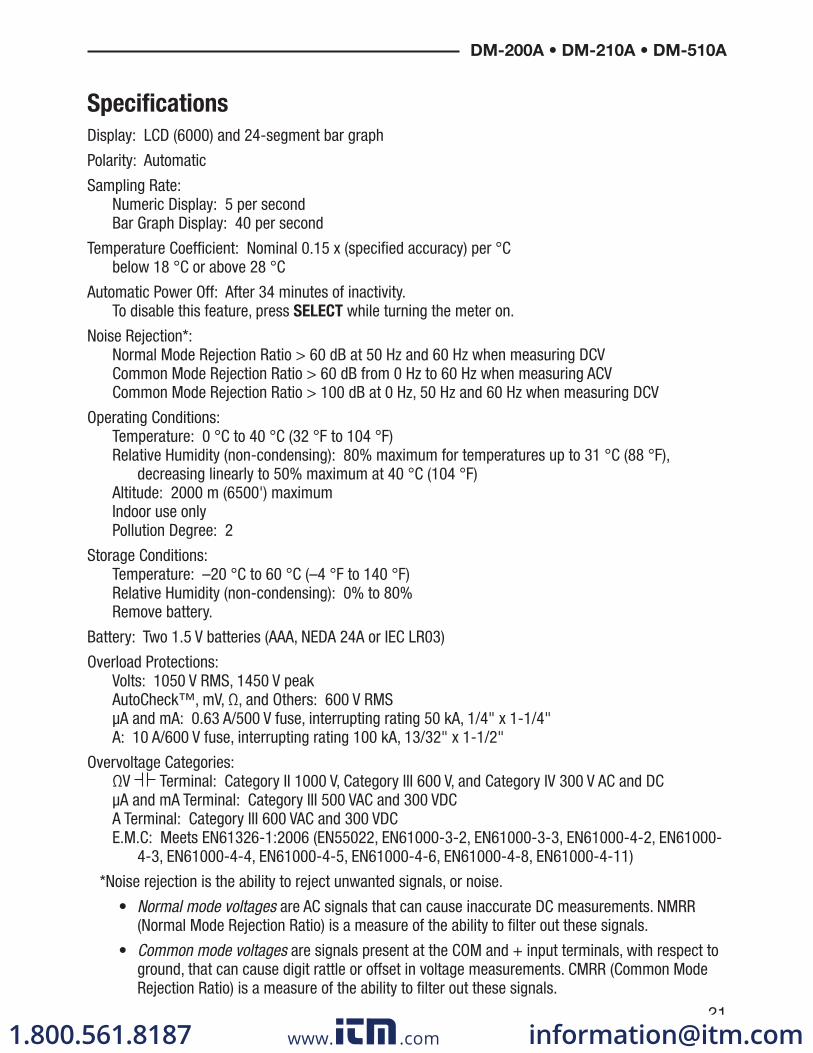
Specifications
Display: LCD (6000) and 24-segment bar graph
Polarity: Automatic
Sampling Rate:Numeric Display: 5 per secondBar Graph Display: 40 per second
Temperature Coefficient: Nominal 0.15 x (specified accuracy) per °C below 18 °C or above 28 °C
Automatic Power Off: After 34 minutes of inactivity. To disable this feature, press SELECT while turning the meter on.
Noise Rejection*:Normal Mode Rejection Ratio > 60 dB at 50 Hz and 60 Hz when measuring DCVCommon Mode Rejection Ratio > 60 dB from 0 Hz to 60 Hz when measuring ACVCommon Mode Rejection Ratio > 100 dB at 0 Hz, 50 Hz and 60 Hz when measuring DCV
Operating Conditions:Temperature: 0 °C to 40 °C (32 °F to 104 °F)Relative Humidity (non-condensing): 80% maximum for temperatures up to 31 °C (88 °F),
decreasing linearly to 50% maximum at 40 °C (104 °F)Altitude: 2000 m (6500') maximumIndoor use onlyPollution Degree: 2
Storage Conditions:Temperature: –20 °C to 60 °C (–4 °F to 140 °F)Relative Humidity (non-condensing): 0% to 80%Remove battery.
Battery: Two 1.5 V batteries (AAA, NEDA 24A or IEC LR03)
Overload Protections:Volts: 1050 V RMS, 1450 V peakAutoCheck™, mV, Ω, and Others: 600 V RMSμA and mA: 0.63 A/500 V fuse, interrupting rating 50 kA, 1/4" x 1-1/4"A: 10 A/600 V fuse, interrupting rating 100 kA, 13/32" x 1-1/2"
Overvoltage Categories:ΩV Terminal: Category II 1000 V, Category III 600 V, and Category IV 300 V AC and DCμA and mA Terminal: Category III 500 VAC and 300 VDCA Terminal: Category III 600 VAC and 300 VDCE.M.C: Meets EN61326-1:2006 (EN55022, EN61000-3-2, EN61000-3-3, EN61000-4-2, EN61000-
4-3, EN61000-4-4, EN61000-4-5, EN61000-4-6, EN61000-4-8, EN61000-4-11)
*Noise rejection is the ability to reject unwanted signals, or noise.
• Normal mode voltages are AC signals that can cause inaccurate DC measurements. NMRR (Normal Mode Rejection Ratio) is a measure of the ability to filter out these signals.
• Common mode voltages are signals present at the COM and + input terminals, with respect to ground, that can cause digit rattle or offset in voltage measurements. CMRR (Common Mode Rejection Ratio) is a measure of the ability to filter out these signals.
www. .com [email protected]
22
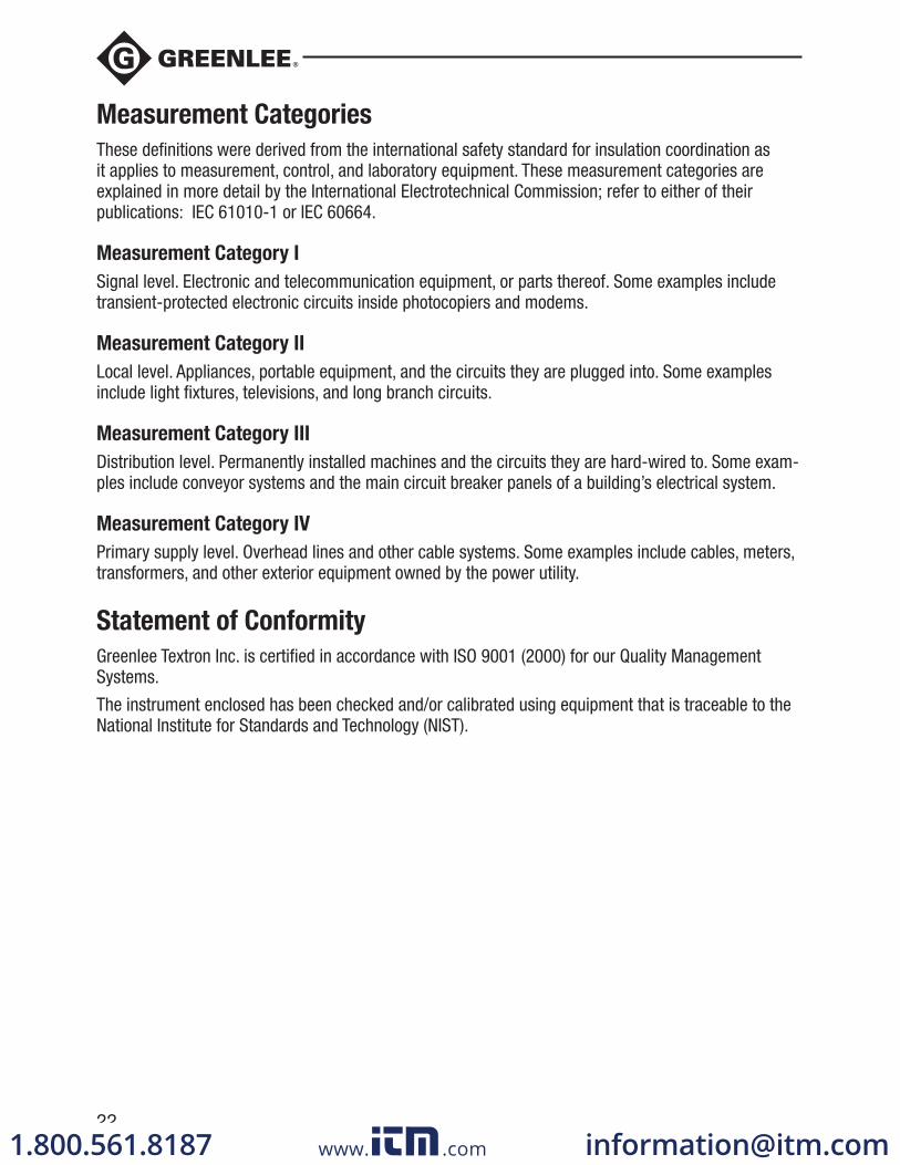
Measurement Categories
These definitions were derived from the international safety standard for insulation coordination as it applies to measurement, control, and laboratory equipment. These measurement categories are explained in more detail by the International Electrotechnical Commission; refer to either of their publications: IEC 61010-1 or IEC 60664.
Measurement Category I
Signal level. Electronic and telecommunication equipment, or parts thereof. Some examples include transient-protected electronic circuits inside photocopiers and modems.
Measurement Category II
Local level. Appliances, portable equipment, and the circuits they are plugged into. Some examples include light fixtures, televisions, and long branch circuits.
Measurement Category III
Distribution level. Permanently installed machines and the circuits they are hard-wired to. Some exam-ples include conveyor systems and the main circuit breaker panels of a building’s electrical system.
Measurement Category IV
Primary supply level. Overhead lines and other cable systems. Some examples include cables, meters, transformers, and other exterior equipment owned by the power utility.
Statement of Conformity
Greenlee Textron Inc. is certified in accordance with ISO 9001 (2000) for our Quality Management Systems.
The instrument enclosed has been checked and/or calibrated using equipment that is traceable to the National Institute for Standards and Technology (NIST).
www. .com [email protected]

DM-200A • DM-210A • DM-510A
23
Maintenance
Electric shock hazard:
Before opening the case, remove the test leads from the circuit and shut off the unit.
Failure to observe these warnings could result in severe injury or death.
Electric shock hazard:
The fuses are an integral part of the overvoltage protection. When fuse replacement is necessary, refer to “Specifications” for the correct type, size, and capacity. Using any other type of fuse will void the overvoltage protection rating of the unit.
Failure to observe this warning could result in severe injury or death.
Replacing the Battery and Fuses
1. Disconnect the unit from the circuit. Turn the unit OFF.
2. Remove the rubber boot.
3. Remove the screw from the back cover.
4. Remove the back cover.
5. Replace and batteries (observe polarity) and/or fuse(s).
6. Replace the cover, screw, and rubber boot.
Cleaning
Periodically wipe the case with a damp cloth and mild detergent; do not use abrasives or solvents.
www. .com [email protected]
DM-200A • DM-210A • DM-510A
71
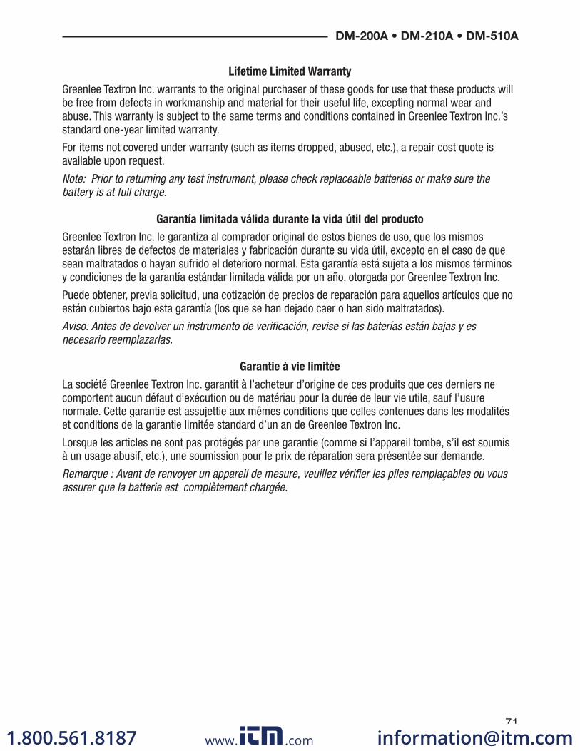
Lifetime Limited Warranty
Greenlee Textron Inc. warrants to the original purchaser of these goods for use that these products will be free from defects in workmanship and material for their useful life, excepting normal wear and abuse. This warranty is subject to the same terms and conditions contained in Greenlee Textron Inc.’s standard one-year limited warranty.
For items not covered under warranty (such as items dropped, abused, etc.), a repair cost quote is available upon request.
Note: Prior to returning any test instrument, please check replaceable batteries or make sure the battery is at full charge.
Garantía limitada válida durante la vida útil del producto
Greenlee Textron Inc. le garantiza al comprador original de estos bienes de uso, que los mismos estarán libres de defectos de materiales y fabricación durante su vida útil, excepto en el caso de que sean maltratados o hayan sufrido el deterioro normal. Esta garantía está sujeta a los mismos términos y condiciones de la garantía estándar limitada válida por un año, otorgada por Greenlee Textron Inc.
Puede obtener, previa solicitud, una cotización de precios de reparación para aquellos artículos que no están cubiertos bajo esta garantía (los que se han dejado caer o han sido maltratados).
Aviso: Antes de devolver un instrumento de verificación, revise si las baterías están bajas y es necesario reemplazarlas.
Garantie à vie limitée
La société Greenlee Textron Inc. garantit à l’acheteur d’origine de ces produits que ces derniers ne comportent aucun défaut d’exécution ou de matériau pour la durée de leur vie utile, sauf l’usure normale. Cette garantie est assujettie aux mêmes conditions que celles contenues dans les modalités et conditions de la garantie limitée standard d’un an de Greenlee Textron Inc.
Lorsque les articles ne sont pas protégés par une garantie (comme si l’appareil tombe, s’il est soumis à un usage abusif, etc.), une soumission pour le prix de réparation sera présentée sur demande.
Remarque : Avant de renvoyer un appareil de mesure, veuillez vérifier les piles remplaçables ou vous assurer que la batterie est complètement chargée.
www. .com [email protected]