Desig
natio
n:
E1
–07
Method
9501—F
ederalTestM
ethodS
tandardN
o.791b
Stan
dard
Sp
ecificatio
nfo
rA
ST
ML
iqu
id-in
-Glass
Th
ermo
meters
1
This
standardis
issuedunder
thefixed
designationE
1;thenum
berim
mediately
following
thedesignation
indicatesthe
yearof
originaladoption
or,inthe
caseof
revision,theyear
oflastrevision.A
number
inparentheses
indicatesthe
yearof
lastreapproval.Asuperscript
epsilon(e)
indicatesan
editorialchange
sincethe
lastrevision
orreapproval.
This
standardhas
beenapproved
foruse
byagencies
ofthe
Departm
entof
Defense.
1.Scope
1.1T
hisspecification
coversliquid-in-glass
thermom
etersgraduated
indegrees
Celsius
ordegrees
Fahrenheitthat
arefrequently
identifiedand
usedin
methods
underthe
jurisdictionof
thevarious
technicalcomm
itteesw
ithinA
STM
.The
varioustherm
ometers
specifiedare
listedin
Table1.
The
inclusionof
anIP
number
inTable
1indicates,
where
appearing,that
thetherm
ometer
specificationhas
beenjointly
agreedupon
bythe
British
Instituteof
Petroleum(IP)
andA
STM
.1.2
This
specification
alsocovers
adjustable-rangeenclosed-scale
thermom
eters,graduated
indegrees
Celsius,
which
areused
inA
STM
methods.
1.3T
heenclosed-scale
thermom
etersare
comm
onlycalled
Beckm
anntherm
ometers.
They
aresuitable
form
easuringsm
alltem
peraturedifferences
notexceeding
6°C
within
alarger
rangeof
temperature.
The
thermom
etersare
unsuitableform
easuringC
elsius-orkelvin-scaletem
peraturesunless
theyhave
beencom
paredw
ithstandard
instruments
imm
ediatelybefore
use.1.4
An
alphabeticlistof
theA
STM
Therm
ometers
includedin
thisstandard
isgiven
inTable
2.1.5
Alist
ofA
STM
Therm
ometers
isgiven
inTable
3to
facilitateselection
accordingto
temperature
range,imm
ersion,and
scale-errorrequirem
ents.
NO
TE
1—For
alisting
oftherm
ometers
recomm
endedfor
generallaboratory
use,theScientific
Apparatus
Makers
Association
Specificationsfor
General
PurposeG
lassL
aboratoryT
hermom
etersm
aybe
consulted. 2
NO
TE
2—It
hasbeen
foundby
experiencethat
theseA
STM
Therm
om-
eters,althoughdeveloped
ingeneral
forspecific
tests,may
alsobe
foundsuitable
forother
applications,thusprecluding
theneed
fornew
thermom
-eter
specificationsdiffering
inonly
minor
features.H
owever,
itis
suggestedthattechnicalcom
mittees
contactSubcomm
itteeE
20.05before
choosinga
currentlyspecified
thermom
eterfor
anew
method
tobe
surethe
thermom
eterw
illbe
suitablefor
theintended
application.
1.6For
non-mercury
alternativesto
E1
thermom
eterssee
SpecificationE
2251.
1.7T
hisstandard
doesnot
purportto
addressall
ofthe
safetyconcerns,
ifany,
associatedw
ithits
use.It
isthe
responsibilityof
theuser
ofthis
standardto
establishappro-
priatesafety
andhealth
practicesand
determine
theapplica-
bilityof
regulatorylim
itationsprior
touse.
1.8W
AR
NIN
G-
Mercury
hasbeen
designatedby
EPA
andm
anystate
agenciesas
ahazardous
material
thatcan
causecentral
nervoussystem
,kidney
andliver
damage.
Mercury,
orits
vapor,m
aybe
hazardousto
healthand
corrosiveto
materials.C
autionshould
betaken
when
handlingm
ercuryand
mercury
containingproducts.
Seethe
applicableproduct
Ma-
terialSafetyD
ataSheet(M
SDS)
fordetails
andE
PA’s
website-
http://ww
w.epa.gov/m
ercury/faq.htm-
foradditional
informa-
tion.U
sersshould
beaw
arethat
sellingm
ercuryand/or
mercury
containingproducts
intoyour
statem
aybe
prohibitedby
statelaw
.
2.R
eferencedD
ocuments
2.1A
STM
Standards:3
E77
TestM
ethodfor
Inspectionand
Verification
ofT
her-m
ometers
E344
Terminology
Relating
toT
hermom
etryand
Hydrom
-etry
E563
Practicefor
Preparationand
Use
ofan
Ice-PointBath
asa
Reference
Temperature
E2251
Specificationfor
Liquid-in-G
lassA
STM
Therm
om-
etersw
ithL
ow-H
azardPrecision
Liquids
3.Term
inology
3.1D
efinitions—T
hedefinitions
givenin
Terminology
E344
apply.3.2
Definitions
ofTerm
sSpecific
toT
hisStandard:
3.2.1adjusting
device,n—
asection
ofthe
instrument
usedto
adjusttheam
ountofm
ercuryin
thebulb
andm
aincapillary
tothat
neededfor
theintended
temperature
interval.3.2.2
bulblength,
n—the
distancefrom
thebottom
ofthe
bulbto
thejunction
ofthe
bulband
thestem
tubing.3.2.3
contractioncham
ber,n—
anenlargem
entof
thecap-
illary,that
will
appearbelow
them
ainscale
orbetw
eenthe
1T
hisspecification
isunder
thejurisdiction
ofA
STM
Com
mittee
E20
onTem
peratureM
easurement
andis
thedirect
responsibilityof
Subcomm
itteeE
20.05on
Liquid-in-G
lassT
hermom
etersand
Hydrom
eters.C
urrentedition
approvedN
ov.1,
2007.Published
Decem
ber2007.
Originally
approvedin
1939.L
astprevious
editionapproved
in2005
asE
1–
05.2
Available
fromSA
MA
Group
ofAssocs.,225
Reinekers,Ste.625,A
lexandria,V
A23314.
3For
referencedA
STM
standards,visit
theA
STM
website,
ww
w.astm
.org,or
contactAST
MC
ustomer
Serviceat
service@astm
.org.For
Annual
Book
ofA
STM
Standardsvolum
einform
ation,referto
thestandard’s
Docum
entSumm
arypage
onthe
AST
Mw
ebsite.
1
Copyright
©A
ST
MInternational,
100B
arrH
arborD
rive,P
OB
oxC
700,W
estC
onshohocken,P
A19428-2959,
United
States.
Copyright A
ST
M International
Provided by IH
S under license w
ith AS
TM
S
old to:Inspectorate Am
erica Corp, 415918
Not for R
esale,03/03/2008 18:43:10 MS
TN
o reproduction or networking perm
itted without license from
IHS
--``,,`,,,,``,`,,```,``,,,`````,-`-`,,`,,`,`,,`---

main
scaleand
theauxiliary
scale,w
hichserves
toreduce
itslength
orto
preventcontraction
ofthe
liquidcolum
ninto
thebulb.
3.2.4diam
eter,n—
thelargest
outsidedim
ensionof
theglass
asm
easuredw
itha
ringgage.
3.2.5expansion
chamber,
n—an
enlargement
atthe
topof
thecapillary
toprovide
protectionagainst
breakagecaused
byexcessive
gaspressure.
3.2.6interval
error,n—
thedeviation
ofthe
nominal
valueof
atem
peratureintervalfrom
itstrue
value;eitherfor
thetotal
range(totalinterval)
orfor
apartof
therange
(partialinterval).3.2.7
saddle,n—
thebottom
supportof
theenclosed
scale.3.2.8
settingtem
perature,n—
thetem
peraturethat
yieldsa
readingof
zeroon
them
ainscale
fora
givenadjustm
entofthe
amount
ofm
ercuryin
thebulb
andm
aincapillary.
3.2.9therm
ometric
liquid,n—the
liquidin
aliquid-in-glass
thermom
eterthat
indicatesthe
valueof
temperature.
3.2.10top
ofthe
thermom
eter,n—
thetop
ofthe
finishedinstrum
ent.3.2.11
totallength,
n—the
distancefrom
thebottom
ofthe
bulbto
thetop
ofthe
finishedtherm
ometer,
includingany
specialfinish
atthe
top.3.2.12
Other
descriptionsof
terms
shallbe
inaccordance
with
theTerm
inologysection
ofTest
Method
E77.
Part
A—
Solid-StemT
hermom
eters
4.Specifications
4.1T
heindividual
thermom
etersshall
conformto
thede-
tailedspecifications
givenin
Table1
andto
thegeneral
requirements
specifiedin
Sections5-15.
4.2T
hermom
etersm
anufacturedto
previousrevisions
ofthis
specificationshall
retainthe
same
AST
Mstatus
asthose
meeting
currentspecifications.
4.3T
heencapsulation
(jacketing)of
theglass
ofliquid-in-
glasstherm
ometers
with
polyfluorinatedhydrocarbons
will
changetheir
performance
andphysical
characteristics,includ-
ing,but
notlim
itedto,
responsetim
e,accuracy,
andphysical
dimensions.
Therefore,
underno
circumstances
shouldan
encapsulatedor
otherwise
modified
AST
Mtherm
ometer
beused
inperform
ingtests
thatspecify
theuse
ofan
AST
Mtherm
ometer.
5.T
ype
5.1T
hetherm
ometers,as
specifiedin
Table1,shallbe
filledw
ithone
ofthe
following
liquids:5.1.1
Mercury,
5.1.2M
ercurythallium
eutecticalloy,
or5.1.3
Tolueneor
othersuitable
liquidcolored
with
aperm
a-nent
reddye.
5.2T
hefilling
abovethe
liquidshall
benitrogen
orother
suitableinert
gas.
6.Stem
6.1Stem
—T
hestem
shallbe
made
ofsuitable
thermom
etertubing
andshall
havea
plainfront
andenam
elback,
unlessotherw
isespecified
inTable
1.6.2
TopF
inish—T
hetop
ofall
thermom
etersspecified
inTable
1shall
havea
plainrounded
finish,exceptthe
following
which
shallhave
thetop
finishindicated
below(unless
indicatedas
optional):6.2.1
Glass
Button
Finish:
Therm
ometers
23C,
24C,
and25C
6.2.2Special
Finish:
6.2.2.1Suitable
forassem
blyin
astandard
304.8-mm
(12-in.)
non-sparkingm
etalarm
orw
ithopen
face;in
acup
caseassem
bly;or
ina
flushingcase
assembly:
Therm
ometers
58C,
58F,59C
,59F,
60C,
60F,97C
,97F,
98C,
98F,130C
,and
130F
6.2.2.2Suitable
forassem
blyin
a12-in.non-sparking
metal
armor
with
openface:
Therm
ometer
99F
6.2.3R
ingTop
(optionalonly)—
Therm
ometers
11Cand
11F.
7.B
ulb
7.1T
hebulb
shallbem
adeof
glasshaving
aviscosity
ofat
least1014.6
poisesat490
°C(914
°F)and
atleast1013.4
poisesat
520°C
(968°F).
7.2T
hermom
etersm
adew
ithbulb
glassesnot
meeting
them
inimum
propertiesin
7.1shall
notbe
subjectedto
tempera-
turesabove
405°C
(760°F)
orbe
continuouslyexposed
totem
peraturesabove
370°C
(700°F).
8.C
apillaryC
learances
8.1T
hefollow
ingdistances
between
graduationsand
thebulb,
andbetw
eengraduations
andenlargem
entsin
thecapil-
lary,shall
bem
inimum
limits
fortherm
ometers
inthis
speci-fication.
NO
TE
3—In
orderfor
atherm
ometer
tobe
usableover
itsentire
graduatedrange,
graduationm
arksshould
notbe
placedtoo
closeto
anyenlargem
entin
thecapillary.
Insufficientim
mersion
ofthe
thermom
etricliquid
inthe
main
bulbor
capillaryenlargem
ent,graduationm
arksplaced
overparts
ofthe
capillarythat
havebeen
changedby
manufacturing
operations,or
graduationsso
closeto
thetop
ofthe
thermom
eterthat
excessivegas
pressureresults
when
thetherm
ometric
liquidis
raisedto
thislevel,
may
leadto
appreciableerrors.
8.1.1A
13-mm
lengthof
unchangedcapillary
between
thebulb
andthe
imm
ersionline
orlow
estgraduation,
ifthe
graduationis
notabove100
°C(212
°F);a30-m
mlength
ifthe
graduationis
above100
°C(212
°F).8.1.2
A5-m
mlength
ofunchanged
capillarybetw
eenan
enlargementand
thegraduation
nextbelow,exceptatthe
topof
thetherm
ometer.
8.1.3A
10-mm
lengthof
unchangedcapillary
between
anenlargem
ent,otherthan
thebulb,and
theim
mersion
lineor
thegraduation
nextabove,
ifthe
graduationis
notabove
100°C
(212°F);
a30-m
mlength
ifthe
graduationis
above100
°C(212
°F).8.1.4
A10-m
mlength
ofunchanged
capillaryabove
thehighest
graduation,ifthere
isan
expansioncham
berat
thetop
ofthe
thermom
eter;a
30-mm
lengthif
thereis
noexpansion
chamber.
Forthe
purposesof
thisrequirem
ent,“an
expansioncham
ber”is
interpretedas
anenlargem
entatthetop
endof
thecapillary
borew
hichshallhave
acapacity
equivalenttonotless
than20
mm
ofunchanged
capillary.
E1
–07
2C
opyright AS
TM
International P
rovided by IHS
under license with A
ST
M
Sold to:Inspectorate A
merica C
orp, 415918N
ot for Resale,03/03/2008 18:43:10 M
ST
No reproduction or netw
orking permitted w
ithout license from IH
S
--``,,`,,,,``,`,,```,``,,,`````,-`-`,,`,,`,`,,`---
8.2It
ispossible
tom
anufacturetherm
ometers
thatcom
plyw
iththe
specificationsgiven
inTable
1,but
donot
meet
therequirem
entsfor
capillaryclearances
givenabove.In
anycase,
thedistances
givenin
thissection
shallbethe
governingfactor.
Under
nocircum
stancesshall
thescales
ontherm
ometers
beplaced
closerthan
thesem
inimum
distances.
9.G
raduationsand
Inscriptions9.1
All
graduationlines,
imm
ersionlines,
figures,and
lettersshall
beclearly
defined,suitably
colored,and
perma-
nent.The
width
andthe
sharpnessof
thegraduation
linesshall
bein
accordancew
ith9.2.
The
middle
ofthe
graduationline
shallbe
determinable.
9.1.1A
suitablyetched
thermom
eterw
iththe
etchedlines
andfigures
filledw
itha
pigment
shallbe
consideredperm
a-nently
marked
providedit
passesthe
testfor
permanency
ofpigm
entin
TestM
ethodE
77.9.1.2
Atherm
ometer
marked
byother
means
shallalso
beconsidered
permanently
marked,provided
itpassesthe
testforperm
anencyof
pigment
inTest
Method
E77.
9.2G
raduationL
ines—A
llgraduation
linesshall
bestraight,of
uniformw
idth,andperpendicular
tothe
axisof
thetherm
ometer.
The
width
ofthe
graduationlines
shallbe
asfollow
s:9.2.1
Group
1—M
aximum
linew
idth0.10
mm
;for
ther-m
ometers
thatm
ayread
tofractions
ofa
division,often
with
magnifying
aids:T
hermom
eters14C
,14F,
26C,
28C,
28F,29C
,29F,
30F,33C
,33F,
34C,
34F,35C
,35F,
44C,
44F,45C
,45F,
46C,
46F,47C
,47F,
48C,
48F,50F,
51F,52C
,56C
,56F,
62C,
62F,63C
,63F,
64C,
64F,65C
,65F,
66C,
66F,67C
,67F,
68C,
68F,69C
,69F,
70C,
70F,72C
,72F,
73C,
73F,74C
,74F,
89C,
90C,
91C,
92C,
93C,
94C,
95C,
96C,
100C,
101C,
110C,
110F,111C
,112C
,113C
,113F,
116C,
117C,
118C,
118F,119C
,119F,
120C,
121C,
126C,
126F,127C
,128C
,128F,
129C,
129F,132C
,133C
,and
137C.
9.2.2G
roup2—
Maxim
umline
width
0.15m
m;
forther-
mom
etersthatm
aybe
readto
thenearesthalf
divisionor
where
thecongestion
ofscaledictates
theuse
ofascale
with
moderate
fineness:T
hermom
eters1C
,1F,
2C,
2F,3C
,3F,
5C,
5F,6C
,6F,
7C,
7F,8C
,8F,
9C,
9F,10C
,10F,
11C,
11F,12C
,12F,
13C,
15C,
15F,16C
,16F,
17C,
17F,18C
,18F,
19C,
19F,20C
,20F,
21C,
21F,22C
,22F,
23C,
24C,
25C,
36C,
37C,
38C,
39C,
40C,
41C,
42C,
43C,
43F,49C
,54C
,54F,
61C,
61F,71C
,71F,
82C,
82F,83C
,83F,
84C,
84F,85C
,85F,
86C,
86F,87C
,87F,
99C,
99F,102C
,103C
,104C
,105C
,106C
,107C
,108F,
109F,114C
,122C
,123C
,124C
,125C
,134C
,135C
,135F,
136C,
and136F.
9.2.3G
roup3—
Maxim
umline
width
0.20m
m;
forther-
mom
etersw
ithm
oreopen
scales,usually
readto
thenearest
division,often
times
underadverse
conditionsw
herea
boldgraduation
istherefore
desired:T
hermom
eters27C
,57C
,57F,
58C,
58F,59C
,59F,
60C,
60F,75F,
76F,77F,
78F,79F,
80F,81F,
88C,
88F,97C
,97F,
98C,
98F,130C
,and
130F.
9.3Im
mersion
Line—
On
partialim
mersion
thermom
etersan
imm
ersionline
shallbeperm
anentlym
arkedon
thefrontof
thetherm
ometer
atthedistance
abovethe
bottomof
thebulb
asspecified
inTable
1w
ithina
toleranceof
60.5
mm
,exceptforT
hermom
eters82F
to87F,w
hichshallhave
noim
mersion
line.T
heim
mersion
inscriptionshallbe
written
incapitalletters
andabbreviated
(forexam
ple,76
mm
imm
ersionshall
bew
ritten76
MM
IMM
).
9.4Term
inalN
umbers—
The
terminal
number
shallbe
infullw
henthere
areone
orm
orenum
beredgraduations
between
itand
thelast
fullnum
ber,before
theterm
inalnum
ber.T
hisrule
neednot
necessarilybe
followed
for:9.4.1
SayboltViscosity
Therm
ometers:
17C,
17F,19C
,19F,
20C,
20F,21C
,21F,
77F,78F,
79F,80F,
and81F
9.4.2K
inematic
ViscosityT
hermom
eters:28F,
29F,30F,
44F,45F,
46F,47F,
48F,72F,
73F,74F,
110F,118F,
126F,128F,
and129F
9.4.3E
nglerViscosity
Therm
ometers:
23C,
24C,
and25C
9.4.4P
recisionT
hermom
eters:65F,
66F,67C
,67F,
and68C
9.4.5Tank
Therm
ometer:
97F
9.4.6Solidification
Point
Therm
ometers:
100Cand
101C
9.4.7R
eidVapor
Pressure:
18Cand
18F
9.4.8O
xidationStability:
22Cand
22F
9.5Scale
Below
Zero—
When
ascale
extendsboth
aboveand
below0
°Cor
0°F,
thetw
oparts
ofthe
scaleshall
bedifferentiated
bysom
em
eans.Exam
plesof
suitablem
eansare:
9.5.1D
ifferentpigmentcolors
forthe
two
partsof
thescale,
9.5.2D
ifferentstyle
ofnum
ericalcharacters
forthe
two
partsof
thescale,
and9.5.3
Use
ofm
inussigns
beforeappropriate
numbers
below0
°Cor
0°F.
10.Special
Inscription
10.1T
hespecial
inscriptionspecified
inTable
1shall
bem
arkedon
thetherm
ometer
incapital
lettersand
Arabic
numbers
without
theuse
ofperiods.
Inaddition
tothe
specialinscription
prescribedin
Table1,
eachtherm
ometer
shallbe
permanently
marked
with
aunique
serialnum
berand
them
anufacturer’stradenam
eor
mark.
10.2E
ngravingR
evisionD
ateon
AST
MT
hermom
eters—Include
yearof
currentrevision
inA
STM
designation(for
example,A
STM
1C-99).
11.P
ermanency
ofP
igment
11.1T
hetestfor
permanency
ofpigm
entshallbeperform
edon
anyconvenientportion
ofthe
scalesection
ofthe
thermom
-eter.T
hepigm
entshallnotchalk,burnout,or
loosenas
aresult
ofthis
test(see
TestM
ethodE
77).
12.B
ulbStability
12.1T
hetest
forbulb
stabilityshall
bem
adefor
thefollow
ingtherm
ometers
inthe
temperature
rangespecified
belowfor
24h.
The
scaleindications
afterthe
testshall
bew
ithinthe
maxim
umscale
errorspecified
inTable
1.O
bser-vations
ofa
referencepoint
beforeand
afterthe
testto
givea
measure
ofthe
degreeof
bulbstability
achievedin
manufac-
ture.The
bulbis
consideredstable
ifthe
changein
indications
E1
–07
3C
opyright AS
TM
International P
rovided by IHS
under license with A
ST
M
Sold to:Inspectorate A
merica C
orp, 415918N
ot for Resale,03/03/2008 18:43:10 M
ST
No reproduction or netw
orking permitted w
ithout license from IH
S
--``,,`,,,,``,`,,```,``,,,`````,-`-`,,`,,`,`,,`---
ofthe
thermom
eterin
thetest
isno
more
than0.7
( 7⁄10)
ofthe
maxim
umscale
errorfound
inTable
1.R
eferenceshould
bem
adeto
TestM
ethodE
77.A
ST
MT
hermom
eterN
umber
TestTem
peratureR
ange
3C,
8C,
10C,
11C,
70C360
to370°C
3F,8F,
10F,11F,
70F680
to700°F
2C,
7C,
69C,
107C280
to290°C
2F,7F,
69F540
to560
°F
13.Scale
Error
13.1T
hermom
etersshall
beverified
andcalibrated
atthe
temperatures
specifiedin
Table4.Partialim
mersion
thermom
-eters
shallbe
calibratedfor
theem
ergentstem
temperatures
specifiedin
Table4.
13.1.1A
tthe
time
ofpurchase,
thescale
errorsshall
bew
ithinthe
maxim
umscale
errorfound
inTable
1.T
heindications
ofm
anyhigh
temperature
andfractionally
gradu-ated
thermom
etersm
aychange
with
time
andcontinued
usedue
tom
inutechanges
inbulb
volume.Periodic
verificationof
thesetherm
ometers,
eitherover
theentire
scaleor
reverifica-tion
ata
referencetem
perature(ice
pointor
steampoint),
inaccordance
with
proceduresset
forthin
TestM
ethodE
77,is
recomm
ended.For
additionalinform
ationon
preparingice-
pointbaths
seePractice
E563.
13.2D
ueto
theapplication
requirements
forrange
andconstruction
ofthe
following
thermom
eters,it
isnot
practicalto
includereference
pointssuch
asthe
iceand
steampoints.
13C,
14C,
14F,17C
,17F,
18C,
18F,19C
,19F,
20C,
20F,21C
,21F,
23C,
24C,
26C,
27C,
38C,
49C,
50F,51F,
56C,
56F,76F,
77F,78F,
79F,80F,
81F,83C
,83F,
84C,
84F,87C
,87F,
91C,
92C,
93C,
96C,
98C,
98F,100C
,101C
,102C
,103C
,104C
,105C
,106C
,107C
,108F,
109F,111C
,116C
,117C
,122C
,123C
,and
124C
14.C
ase
14.1E
achtherm
ometer
shallbe
suppliedin
asuitable
caseon
which
shallappear
thefollow
ingm
arking(except
when
atransparentcase
isused):the
letters“A
STM
,”the
thermom
eternum
ber(33C
,33F,
etc.),and
thetem
peraturerange.
15.M
ethodsof
Verification
andC
alibration
15.1T
hermom
etersshall
beverified
andcalibrated
atthe
specifiedim
mersion
inaccordance
with
TestM
ethodE
77.
15.2For
partialim
mersion
thermom
eters,careful
consider-ation
ofem
ergentstem
temperatures
shallbe
observed.
15.2.1D
uringthe
manufacture
ofpartial
imm
ersionther-
mom
eters,the
manufacturer
shallcalibrate
thetherm
ometers
sothe
indicatedtem
peraturesare
within
them
aximum
permis-
sibleerrors
foundin
Table1
when
theem
ergentstemtem
pera-tures
foundin
Table4
areapplied
tothe
readings.
NO
TE
4—To
achievethe
requirements
in15.2.1,the
manufacturer
may
haveto
measure
emergent
stemtem
peraturesabove
itsbath,
calculatecorrection
factors,andoffsetits
calibrationsaccordingly.See
TestMethod
E77
forthe
procedureto
correctfor
emergent
stemtem
peratures.
E1
–07
4C
opyright AS
TM
International P
rovided by IHS
under license with A
ST
M
Sold to:Inspectorate A
merica C
orp, 415918N
ot for Resale,03/03/2008 18:43:10 M
ST
No reproduction or netw
orking permitted w
ithout license from IH
S
--``,,`,,,,``,`,,```,``,,,`````,-`-`,,`,,`,`,,`---
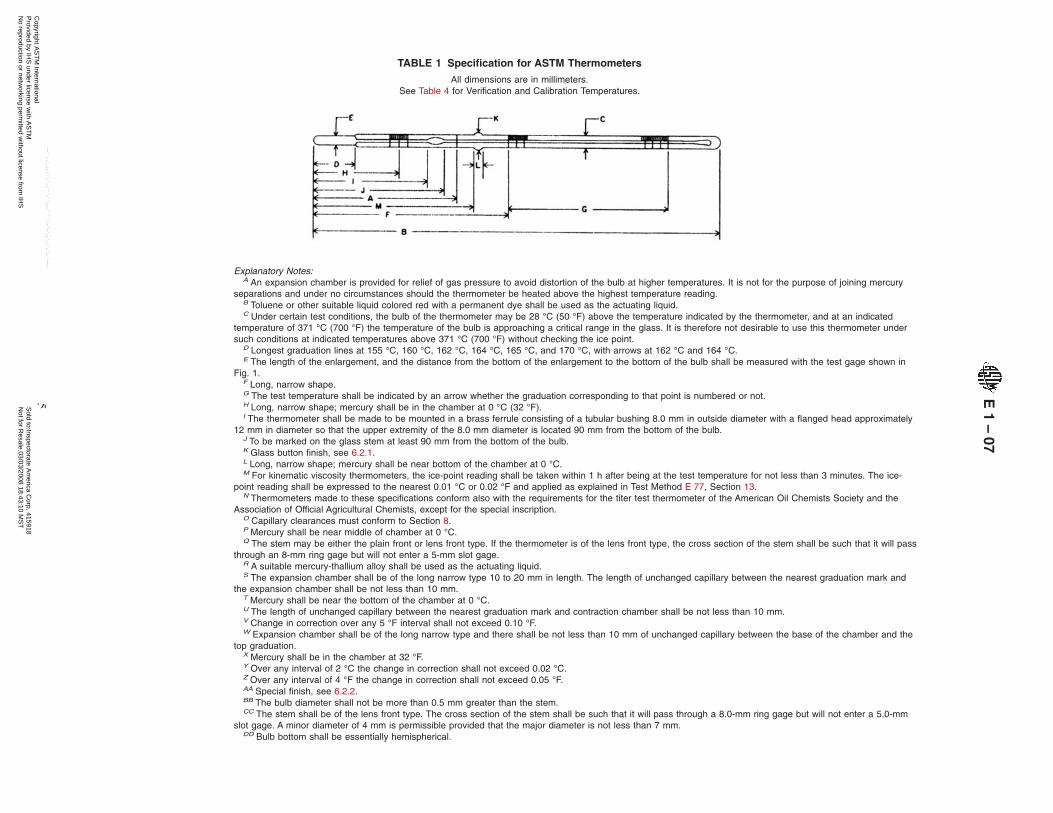
TABLE 1 Specification for ASTM Thermometers
All dimensions are in millimeters.See Table 4 for Verification and Calibration Temperatures.
Explanatory Notes:A An expansion chamber is provided for relief of gas pressure to avoid distortion of the bulb at higher temperatures. It is not for the purpose of joining mercury
separations and under no circumstances should the thermometer be heated above the highest temperature reading.B Toluene or other suitable liquid colored red with a permanent dye shall be used as the actuating liquid.C Under certain test conditions, the bulb of the thermometer may be 28 °C (50 °F) above the temperature indicated by the thermometer, and at an indicated
temperature of 371 °C (700 °F) the temperature of the bulb is approaching a critical range in the glass. It is therefore not desirable to use this thermometer undersuch conditions at indicated temperatures above 371 °C (700 °F) without checking the ice point.
D Longest graduation lines at 155 °C, 160 °C, 162 °C, 164 °C, 165 °C, and 170 °C, with arrows at 162 °C and 164 °C.E The length of the enlargement, and the distance from the bottom of the enlargement to the bottom of the bulb shall be measured with the test gage shown in
Fig. 1.F Long, narrow shape.G The test temperature shall be indicated by an arrow whether the graduation corresponding to that point is numbered or not.H Long, narrow shape; mercury shall be in the chamber at 0 °C (32 °F).I The thermometer shall be made to be mounted in a brass ferrule consisting of a tubular bushing 8.0 mm in outside diameter with a flanged head approximately
12 mm in diameter so that the upper extremity of the 8.0 mm diameter is located 90 mm from the bottom of the bulb.J To be marked on the glass stem at least 90 mm from the bottom of the bulb.K Glass button finish, see 6.2.1.L Long, narrow shape; mercury shall be near bottom of the chamber at 0 °C.M For kinematic viscosity thermometers, the ice-point reading shall be taken within 1 h after being at the test temperature for not less than 3 minutes. The ice-
point reading shall be expressed to the nearest 0.01 °C or 0.02 °F and applied as explained in Test Method E 77, Section 13.N Thermometers made to these specifications conform also with the requirements for the titer test thermometer of the American Oil Chemists Society and the
Association of Official Agricultural Chemists, except for the special inscription.O Capillary clearances must conform to Section 8.P Mercury shall be near middle of chamber at 0 °C.Q The stem may be either the plain front or lens front type. If the thermometer is of the lens front type, the cross section of the stem shall be such that it will pass
through an 8-mm ring gage but will not enter a 5-mm slot gage.R A suitable mercury-thallium alloy shall be used as the actuating liquid.S The expansion chamber shall be of the long narrow type 10 to 20 mm in length. The length of unchanged capillary between the nearest graduation mark and
the expansion chamber shall be not less than 10 mm.T Mercury shall be near the bottom of the chamber at 0 °C.U The length of unchanged capillary between the nearest graduation mark and contraction chamber shall be not less than 10 mm.V Change in correction over any 5 °F interval shall not exceed 0.10 °F.W Expansion chamber shall be of the long narrow type and there shall be not less than 10 mm of unchanged capillary between the base of the chamber and the
top graduation.X Mercury shall be in the chamber at 32 °F.Y Over any interval of 2 °C the change in correction shall not exceed 0.02 °C.Z Over any interval of 4 °F the change in correction shall not exceed 0.05 °F.AA Special finish, see 6.2.2.BB The bulb diameter shall not be more than 0.5 mm greater than the stem.CC The stem shall be of the lens front type. The cross section of the stem shall be such that it will pass through a 8.0-mm ring gage but will not enter a 5.0-mm
slot gage. A minor diameter of 4 mm is permissible provided that the major diameter is not less than 7 mm.DD Bulb bottom shall be essentially hemispherical.
E1
–07
5C
opyright AS
TM
International P
rovided by IHS
under license with A
ST
M
Sold to:Inspectorate A
merica C
orp, 415918N
ot for Resale,03/03/2008 18:43:10 M
ST
No reproduction or netw
orking permitted w
ithout license from IH
S
--``,,`,,,,``,`,,```,``,,,`````,-`-`,,`,,`,`,,`---
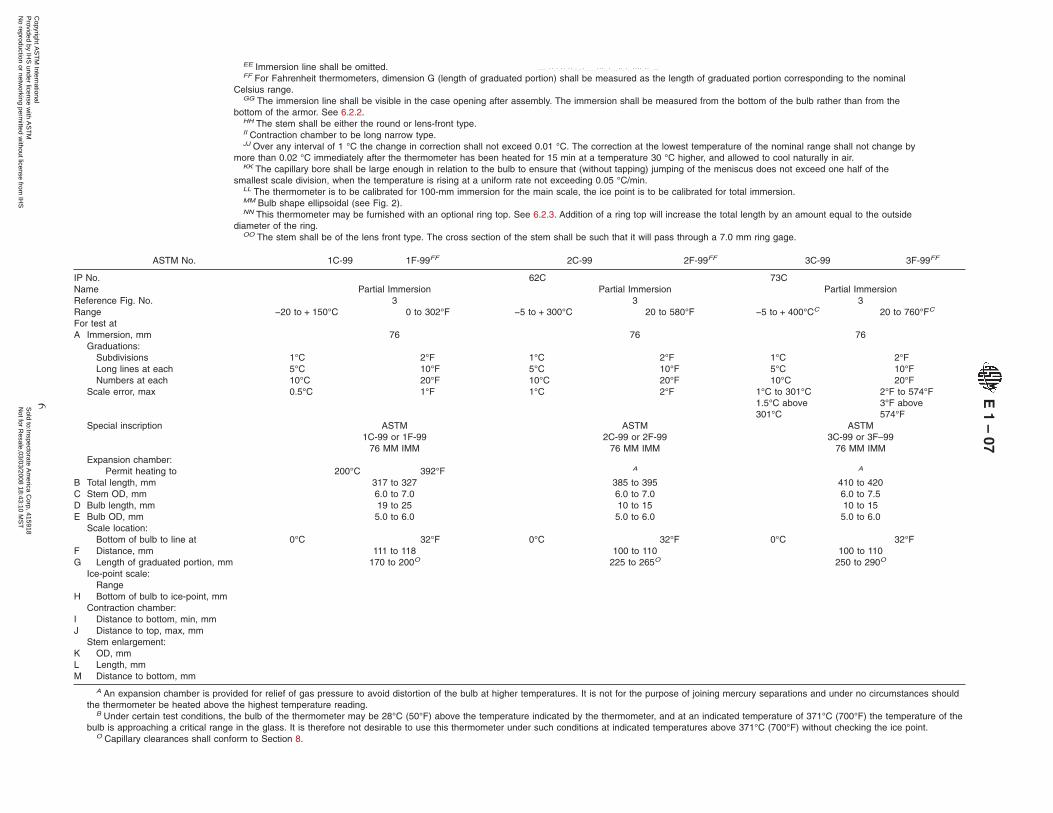
EE Immersion line shall be omitted.FF For Fahrenheit thermometers, dimension G (length of graduated portion) shall be measured as the length of graduated portion corresponding to the nominal
Celsius range.GG The immersion line shall be visible in the case opening after assembly. The immersion shall be measured from the bottom of the bulb rather than from the
bottom of the armor. See 6.2.2.HH The stem shall be either the round or lens-front type.II Contraction chamber to be long narrow type.JJ Over any interval of 1 °C the change in correction shall not exceed 0.01 °C. The correction at the lowest temperature of the nominal range shall not change by
more than 0.02 °C immediately after the thermometer has been heated for 15 min at a temperature 30 °C higher, and allowed to cool naturally in air.KK The capillary bore shall be large enough in relation to the bulb to ensure that (without tapping) jumping of the meniscus does not exceed one half of the
smallest scale division, when the temperature is rising at a uniform rate not exceeding 0.05 °C/min.LL The thermometer is to be calibrated for 100-mm immersion for the main scale, the ice point is to be calibrated for total immersion.MM Bulb shape ellipsoidal (see Fig. 2).NN This thermometer may be furnished with an optional ring top. See 6.2.3. Addition of a ring top will increase the total length by an amount equal to the outside
diameter of the ring.OO The stem shall be of the lens front type. The cross section of the stem shall be such that it will pass through a 7.0 mm ring gage.
ASTM No. 1C-99 1F-99FF 2C-99 2F-99FF 3C-99 3F-99FF
IP No. 62C 73CName Partial Immersion Partial Immersion Partial ImmersionReference Fig. No. 3 3 3Range −20 to + 150°C 0 to 302°F −5 to + 300°C 20 to 580°F −5 to + 400°CC 20 to 760°FC
For test atA Immersion, mm 76 76 76
Graduations:Subdivisions 1°C 2°F 1°C 2°F 1°C 2°FLong lines at each 5°C 10°F 5°C 10°F 5°C 10°FNumbers at each 10°C 20°F 10°C 20°F 10°C 20°F
Scale error, max 0.5°C 1°F 1°C 2°F 1°C to 301°C1.5°C above301°C
2°F to 574°F3°F above574°F
Special inscription ASTM ASTM ASTM1C-99 or 1F-99 2C-99 or 2F-99 3C-99 or 3F–99
76 MM IMM 76 MM IMM 76 MM IMMExpansion chamber:
Permit heating to 200°C 392°F A A
B Total length, mm 317 to 327 385 to 395 410 to 420C Stem OD, mm 6.0 to 7.0 6.0 to 7.0 6.0 to 7.5D Bulb length, mm 19 to 25 10 to 15 10 to 15E Bulb OD, mm 5.0 to 6.0 5.0 to 6.0 5.0 to 6.0
Scale location:Bottom of bulb to line at 0°C 32°F 0°C 32°F 0°C 32°F
F Distance, mm 111 to 118 100 to 110 100 to 110G Length of graduated portion, mm 170 to 200O 225 to 265O 250 to 290O
Ice-point scale:Range
H Bottom of bulb to ice-point, mmContraction chamber:
I Distance to bottom, min, mmJ Distance to top, max, mm
Stem enlargement:K OD, mmL Length, mmM Distance to bottom, mm
A An expansion chamber is provided for relief of gas pressure to avoid distortion of the bulb at higher temperatures. It is not for the purpose of joining mercury separations and under no circumstances shouldthe thermometer be heated above the highest temperature reading.
B Under certain test conditions, the bulb of the thermometer may be 28°C (50°F) above the temperature indicated by the thermometer, and at an indicated temperature of 371°C (700°F) the temperature of thebulb is approaching a critical range in the glass. It is therefore not desirable to use this thermometer under such conditions at indicated temperatures above 371°C (700°F) without checking the ice point.
O Capillary clearances shall conform to Section 8.
E1
–07
6C
opyright AS
TM
International P
rovided by IHS
under license with A
ST
M
Sold to:Inspectorate A
merica C
orp, 415918N
ot for Resale,03/03/2008 18:43:10 M
ST
No reproduction or netw
orking permitted w
ithout license from IH
S
--``,,`,,,,``,`,,```,``,,,`````,-`-`,,`,,`,`,,`---

TABLE 1 ContinuedFF For Fahrenheit thermometers, dimension G (length of graduated portion) shall be measured as the length of graduated portion corresponding to the nominal Celsius range.
ASTM No. 5C-86 5F-86FF 6C-86 6F-86FF 7C-86 7F-86FF
IP No. 1C 2C 5CName Cloud and Pour Low Cloud and PourB Low DistillationReference Fig. No. 3 3 4Range −38 to + 50°C −36 to + 120°F −80 to + 20°C −112 to + 70°F −2 to + 300°C 30 to 580°FFor test atA Immersion, mm 108 76 total
Graduations:Subdivisions 1°C 2°F 1°C 2°F 1°C 2°FLong lines at each 5°C 10°F 5°C 10°F 5°C 10°FNumbers at each 10°C 20°F 10°C 20°F 10°C 20°F
Scale error, max 0.5°C 1°F 1°C to − 33°C2°C below − 33°C
2°F to − 28°F4°F below − 28°F
0.5°C to 150°C1°C above 150°C
1°F to 300°F2°F above 300°F
Special inscription ASTM5C-86 or 5F–86
108 MM IMM
ASTM6C-86 or 6F-86
76 MM IMM
ASTM7C-86 or 7F–86
Expansion chamber:Permit heating to 100°C 212°F 60°C 140°F A
B Total length, mm 225 to 235 225 to 235 380 to 390C Stem OD, mm 6.0 to 8.0 6.0 to 8.0 6.0 to 8.0D Bulb length, mm 7 to 10 7 to 10 10 to 15E Bulb OD, mm ≤5.5 and ≥stem ≤5.0 and ≥stem ≤5.0 and ≥stem
Scale location:Bottom of bulb to line at −38°C −36°F −70°C −94°F 0°C 32°F
F Distance, mm 120 to 130 100 to 120 100 to 110G Length of graduated portion, mm 65 to 85O 70 to 100O 225 to 255O
Ice-point scale:Range
H Bottom of bulb to ice-point, mmContraction chamber:
I Distance to bottom, min, mmJ Distance to top, max, mm
Stem enlargement:K OD, mmL Length, mmM Distance to bottom, mm
A An expansion chamber is provided for relief of gas pressure to avoid distortion of the bulb at higher temperatures. It is not for the purpose of joining mercury separations and under no circumstances shouldthe thermometer be heated above the highest temperature reading.
B Toluene or other suitable liquid colored red with a permanent dye shall be used as the actuating liquid.O Capillary clearances shall conform to Section 8.FF For Fahrenheit thermometers, dimension G (length of graduated portion) shall be measured as the length of graduated portion corresponding to the nominal Celsius range.
E1
–07
7C
opyright AS
TM
International P
rovided by IHS
under license with A
ST
M
Sold to:Inspectorate A
merica C
orp, 415918N
ot for Resale,03/03/2008 18:43:10 M
ST
No reproduction or netw
orking permitted w
ithout license from IH
S
--``,,`,,,,``,`,,```,``,,,`````,-`-`,,`,,`,`,,`---

TABLE 1 Continued
ASTM No. 8C-86 8F-86FF 9C-86 9F-86FF 10C-86 10F-86FF
IP No. 6C 15C 16CName High Distillation Low-Pensky-Martens High-Pensky-MartensReference Fig. No. 4 5 5Range −2 to + 400°CC 30 to 760°FC −5 to + 110°C 20 to 230°F 90 to 370°C 200 to 700°FFor test atA Immersion, mm total 57 57
Graduations:Subdivisions 1°C 2°F 0.5°C 1°F 2°C 5°FLong lines at each 5°C 10°F 1°C and 5°C 5°F 10°C 25°FNumbers at each 10°C 20°F 5°C 10°F 20°C 50°F
Scale error, max 1°C to 300°C1.5°C above 300°C
2°F to 570°F3°F above 570°F
0.5°C 1°F 1°C to 260°C2°C above 260°C
2.5°F to 500°F3.5°F above 500°F
Special inscription ASTM8C-86 or 8F-86
ASTM9C-86 or 9F–86
57 MM IMM
ASTM10C-86 or 10F–86
57 MM IMMExpansion chamber:
Permit heating to A 160°C 320°F A
B Total length, mm 380 to 390 285 to 295 285 to 295C Stem OD, mm 6.0 to 8.0 6.0 to 7.0 6.0 to 7.0D Bulb length, mm 10 to 15 9 to 13 7 to 10E Bulb OD, mm ≤5.0 and ≥stem ≤5.5 and ≥stem ≤4.5 and ≥stem
Scale location:Bottom of bulb to line at 0°C 32°F 0°C 32°F 90°C 200°F
F Distance, mm 30 to 40 85 to 95 80 to 90G Length of graduated portion, mm 290 to 330O 140 to 175O 145 to 180O
Ice-point scale:Range
H Bottom of bulb to ice-point, mmContraction chamber:
I Distance to bottom, min, mmJ Distance to top, max, mm
Stem enlargementK OD, mm 7.5 to 8.5 7.5 to 8.5L Length, mm 2.5 to 5.0E 2.5 to 5.0E
M Distance to bottom, mm 64 to 66 64 to 66
A An expansion chamber is provided for relief of gas pressure to avoid distortion of the bulb at higher temperatures. It is not for the purpose of joining mercury separations and under no circumstances shouldthe thermometer be heated above the highest temperature reading.
C Under certain test conditions, the bulb of the thermometer may be 28°C (50°F) above the temperature indicated by the thermometer, and at an indicated temperature of 371°C (700°F) the temperature of thebulb is approaching a critical range in the glass. It is therefore not desirable to use this thermometer under such conditions at indicated temperatures above 371°C (700°F) without checking the ice point.
E The length of the enlargement, and the distance from the bottom of the enlargement to the bottom of the bulb shall be measured with the test gage shown in Fig. 1.O Capillary clearances shall conform to Section 8.FF For Fahrenheit thermometers, dimension G (length of graduated portion) shall be measured as the length of graduated portion corresponding to the nominal Celsius range.
E1
–07
8C
opyright AS
TM
International P
rovided by IHS
under license with A
ST
M
Sold to:Inspectorate A
merica C
orp, 415918N
ot for Resale,03/03/2008 18:43:10 M
ST
No reproduction or netw
orking permitted w
ithout license from IH
S
--``,,`,,,,``,`,,```,``,,,`````,-`-`,,`,,`,`,,`---

TABLE 1 Continued
ASTM No. 11C-86 11F-86FF 12C-86 12F-86FF 13C-86
IP No. 28C 64C 64F 47CName Cleveland Open Flash Density-Wide Range Loss on HeatReference Fig. No. 3 4 9Range −6 to + 400°CC 20 to 760°FC −20 to + 102°C −5 to + 215°F 155 to 170°CFor test atA Immersion, mm 25 total total
Graduations:Subdivisions 2°C 5°F 0.2°C 0.5°F 0.5°CLong lines at each 10°C 10°F 1°C 1°F 1°CD
Numbers at each 20°C 20°F 2°C 5°F 155°C, 160°C, 165°C,170°C
Scale error, max 2°C to 260°C4°C above 260°C
5°F to 500°F7°F above 500°F
0.15°C 0.25°F 0.5°C
Special inscription ASTM11C-86 or 11F–86
25 MM IMM
ASTM12C-86 or 12F–86
ASTM13C-86
Expansion chamber:Permit heating to A 150°C 300°F 200°C
B Total length, mm 305 to 315NN 415 to 425 150 to 160C Stem OD, mm 6.0 to 8.0 6.0 to 8.0 5.5 to 7.0D Bulb length, mm 7 to 10 15 to 20 10 to 15E Bulb OD, mm ≤4.5 and ≥stem bulb size ≥stem size ≤5.0 and ≥stem
Scale location:Bottom of bulb to line at 0°C 32°F −20°C −4°F 155°C
F Distance, mm 45 to 55 35 to 50 50 to 60G Length of graduated portion,
mm210 to 240O 305 to 350O 40 to 60O
Ice-point scale:Range
H Bottom of bulb to ice-point,mmContraction chamber:
I Distance to bottom, min, mmJ Distance to top, max, mm 30F
Stem enlargement:K OD, mmL Length, mmM Distance to bottom, mm
A An expansion chamber is provided for relief of gas pressure to avoid distortion of the bulb at higher temperatures. It is not for the purpose of joining mercury separations, and under nocircumstances should the thermometer be heated above the highest temperature reading.
C Under certain test conditions, the bulb of the thermometer may be 28°C (50°F) above the temperature indicated by the thermometer, and at an indicated temperature of 371°C (700°F) thetemperature of the bulb is approaching a critical range in the glass. It is therefore not desirable to use this thermometer under such conditions at indicated temperatures above 371°C (700°F) withoutchecking the ice point.
D Longest graduation lines at 155°C, 160°C, 162°C, 164°C, 165°C, and 170°C, with arrows at 162°C and 164°C.F Long, narrow shape.O Capillary clearances shall conform to Section 8.FF For Fahrenheit thermometers, dimension G (length of graduated portion) shall be measured as the length of graduated portion corresponding to the nominal Celsius range.NN This thermometer may be furnished with an optional ring top. See 6.2.3. Addition of a ring top will increase the total length by an amount equal to the outside diameter of the ring.
E1
–07
9C
opyright AS
TM
International P
rovided by IHS
under license with A
ST
M
Sold to:Inspectorate A
merica C
orp, 415918N
ot for Resale,03/03/2008 18:43:10 M
ST
No reproduction or netw
orking permitted w
ithout license from IH
S
--``,,`,,,,``,`,,```,``,,,`````,-`-`,,`,,`,`,,`---

TABLE 1 Continued
ASTM No. 14C-86 14F-86FF 15C-86 15F-86FF 16C-86 16F-86FF
IP No. 17C 60C 61CName Wax Melting Point Low Softening Point High Softening PointReference Fig. No. 7 4 4Range 38 to 82°C 100 to 180°F −2 to + 80°C 30 to 180°F 30 to 200°C 85 to 392°FFor test atA Immersion, mm 79 total total
Graduations:Subdivisions 0.1°C 0.2°F 0.2°C 0.5°F 0.5°C 1°FLong lines at each 0.5°C 1°F 1°C 1°F 1°C 5°FNumbers at each 1°C 2°F 2°C 5°F 5°C 10°F
Scale error, max 0.1°C 0.2°F 0.2°C 0.4°F 0.3°C 0.5°FSpecial inscription ASTM
14C-86 or 14F–8679 MM IMM
ASTM15C-86 or 15F–86
ASTM16C-86 or 16F–86
Expansion chamber:Permit heating to 100°C 212°F 130°C 270°F 250°C 482°F
B Total length, mm 370 to 380 390 to 400 390 to 400C Stem OD, mm 6.0 to 8.0 6.0 to 8.0 6.0 to 8.0D Bulb length, mm 18 to 28 9 to 14 9 to 14E Bulb OD, mm 5.0 to 6.0 4.5 to 5.5 4.5 to 5.5
Scale location:Bottom of bulb to line at 40°C 104°F 0°C 32°F 30°C 86°F
F Distance, mm 115 to 125 75 to 90 75 to 90G Length of graduated portion, mm 210 to 240O 245 to 285O 245 to 280O
Ice-point scale:Range
H Bottom of bulb to ice-point, mmContraction chamber:
I Distance to bottom, min, mmJ Distance to top, max, mm 41
Stem enlargement:K OD, mmL Length, mmM Distance to bottom, mm
O Capillary clearances shall conform to Section 8.FF For Fahrenheit thermometers, dimension G (length of graduated portion) shall be measured as the length of graduated portion corresponding to the nominal Celsius range.
E1
–07
10C
opyright AS
TM
International P
rovided by IHS
under license with A
ST
M
Sold to:Inspectorate A
merica C
orp, 415918N
ot for Resale,03/03/2008 18:43:10 M
ST
No reproduction or netw
orking permitted w
ithout license from IH
S
--``,,`,,,,``,`,,```,``,,,`````,-`-`,,`,,`,`,,`---

TABLE 1 Continued
ASTM No. 17C-86 17F-86FF 18C-86 18F-86FF 19C-86 19F-86FF
IP No. 23CName Saybolt Viscosity Reid Vapor Pressure Saybolt ViscosityReference Fig. No. 8 8 8Range 19 to 27°C 66 to 80°F 34 to 42°C 94 to 108°F 49 to 57°C 120 to 134°FFor test at 21.1 and 25°CG 70 and 77°FG 37.8°CG 100°FG 50 and 54.4°CG 122 and 130°FG
A Immersion, mm total total totalGraduations:
Subdivisions 0.1°C 0.2°F 0.1°C 0.2°F 0.1°C 0.2°FLong lines at each 0.5°C 1°F 0.5°C 1°F 0.5°C 1°FNumbers at each 1°C, except 21 2°F 1°C 2°F 1°C, except 54 2°F
Scale error, max 0.1°C 0.2°F 0.1°C 0.2°F 0.1°C 0.2°FSpecial inscription ASTM
17C-86 or 17F-86ASTM
18C-86 or 18F-86ASTM
19C-86 or 19F-86Expansion chamber:
Permit heating to 100°C 212°F 100°C 212°F 115°C 240°FB Total length, mm 270 to 280 270 to 280 270 to 280C Stem OD, mm 6.0 to 7.0 6.0 to 7.0 6.0 to 7.0D Bulb length, mm 25 to 35 25 to 35 25 to 35E Bulb OD, mm ≤5.0 and ≥stem ≥stem ≤5.0 and ≥stem
Scale location:Bottom of bulb to line at 19°C 66°F 34°C 94°F 49°C 120°F
F Distance, mm 135 to 150 130 to 150 135 to 150G Length of graduated portion, mm 67 to 101O 60 to 90O 67 to 101O
Ice-point scale:Range
H Bottom of bulb to ice-point, mmContraction chamber:
I Distance to bottom, min, mmJ Distance to top, max, mm 60H 60H 60H
Stem enlargement:K OD, mm 8.0 to 10.0 8.0 to 10.0 8.0 to 10.0L Length, mm 4.0 to 7.0 4.0 to 7.0 4.0 to 7.0M Distance to bottom, mm 112 to 116 112 to 116 112 to 116
G The test temperatures shall be indicated by an arrow whether the graduation corresponding to that point is numbered or not.H Long, narrow shape; mercury shall be in the chamber at 0°C (32°F).O Capillary clearances shall conform to Section 8.FF For Fahrenheit thermometers, dimension G (length of graduated portion) shall be measured as the length of graduated portion corresponding to the nominal Celsius range.
E1
–07
11C
opyright AS
TM
International P
rovided by IHS
under license with A
ST
M
Sold to:Inspectorate A
merica C
orp, 415918N
ot for Resale,03/03/2008 18:43:10 M
ST
No reproduction or netw
orking permitted w
ithout license from IH
S
--``,,`,,,,``,`,,```,``,,,`````,-`-`,,`,,`,`,,`---
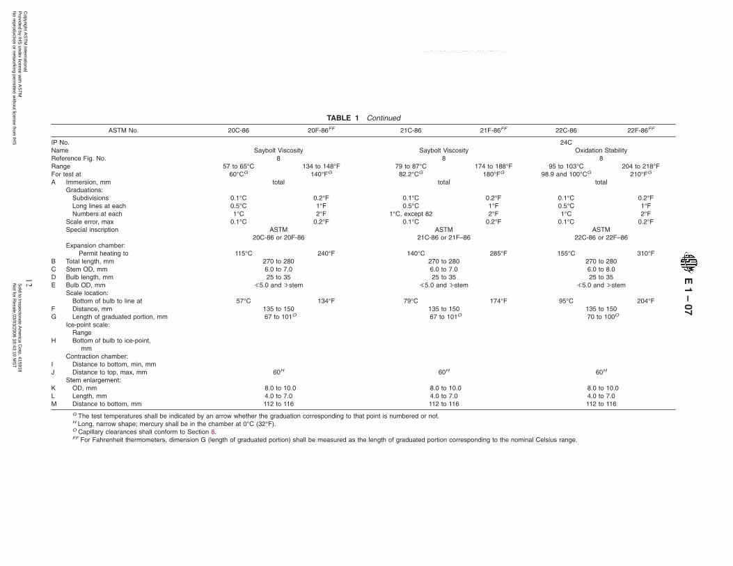
TABLE 1 Continued
ASTM No. 20C-86 20F-86FF 21C-86 21F-86FF 22C-86 22F-86FF
IP No. 24CName Saybolt Viscosity Saybolt Viscosity Oxidation StabilityReference Fig. No. 8 8 8Range 57 to 65°C 134 to 148°F 79 to 87°C 174 to 188°F 95 to 103°C 204 to 218°FFor test at 60°CG 140°FG 82.2°CG 180°FG 98.9 and 100°CG 210°FG
A Immersion, mm total total totalGraduations:
Subdivisions 0.1°C 0.2°F 0.1°C 0.2°F 0.1°C 0.2°FLong lines at each 0.5°C 1°F 0.5°C 1°F 0.5°C 1°FNumbers at each 1°C 2°F 1°C, except 82 2°F 1°C 2°F
Scale error, max 0.1°C 0.2°F 0.1°C 0.2°F 0.1°C 0.2°FSpecial inscription ASTM
20C-86 or 20F-86ASTM
21C-86 or 21F–86ASTM
22C-86 or 22F–86Expansion chamber:
Permit heating to 115°C 240°F 140°C 285°F 155°C 310°FB Total length, mm 270 to 280 270 to 280 270 to 280C Stem OD, mm 6.0 to 7.0 6.0 to 7.0 6.0 to 8.0D Bulb length, mm 25 to 35 25 to 35 25 to 35E Bulb OD, mm ≤5.0 and ≥stem ≤5.0 and ≥stem ≤5.0 and ≥stem
Scale location:Bottom of bulb to line at 57°C 134°F 79°C 174°F 95°C 204°F
F Distance, mm 135 to 150 135 to 150 135 to 150G Length of graduated portion, mm 67 to 101O 67 to 101O 70 to 100O
Ice-point scale:Range
H Bottom of bulb to ice-point,mm
Contraction chamber:I Distance to bottom, min, mmJ Distance to top, max, mm 60H 60H 60H
Stem enlargement:K OD, mm 8.0 to 10.0 8.0 to 10.0 8.0 to 10.0L Length, mm 4.0 to 7.0 4.0 to 7.0 4.0 to 7.0M Distance to bottom, mm 112 to 116 112 to 116 112 to 116
G The test temperatures shall be indicated by an arrow whether the graduation corresponding to that point is numbered or not.H Long, narrow shape; mercury shall be in the chamber at 0°C (32°F).O Capillary clearances shall conform to Section 8.FF For Fahrenheit thermometers, dimension G (length of graduated portion) shall be measured as the length of graduated portion corresponding to the nominal Celsius range.
E1
–07
12C
opyright AS
TM
International P
rovided by IHS
under license with A
ST
M
Sold to:Inspectorate A
merica C
orp, 415918N
ot for Resale,03/03/2008 18:43:10 M
ST
No reproduction or netw
orking permitted w
ithout license from IH
S
--``,,`,,,,``,`,,```,``,,,`````,-`-`,,`,,`,`,,`---

TABLE 1 Continued
ASTM No. 23C-86 24C-86 25C-86
IP No.Name Engler ViscosityI Engler ViscosityI Engler ViscosityI
Reference Fig. No. 7K 7K 7K
Range 18 to 28°C 39 to 54°C 95 to 105°CFor test at 25°C 40 and 50°C 100°CA Immersion, mm 90 90 90
Graduations:Subdivisions 0.2°C 0.2°C 0.2°CLong lines at each 1°C 1°C 1°CNumbers at each 2°C full figures at 25 2°C full figures at 40 and 50 2°C full figures at 100
Scale error, max 0.1°C at 25°C 0.1°C at 40 and 50°C 0.1°C at 100°CSpecial inscription ASTM
23C-8690 MM IMMJ
ASTM24C-8690 MM IMMJ
ASTM25C-8690 MM IMMJ
Expansion chamber:Permit heating to 100°C 105°C 155°C
B Total length, mm 207 to 217 232 to 242 207 to 217C Stem OD, mm 5.5 to 6.5 5.5 to 6.5 5.5 to 6.5D Bulb length, mm 13 to 19 13 to 19 13 to 19E Bulb OD, mm 5.5 to 6.5 5.5 to 6.5 5.5 to 6.5
Scale location:Bottom of bulb to line at 18°C 39°C 95°C
F Distance, mm 108 to 118 108 to 118 108 to 118G Length of graduated portion, mm 42 to 69O 67 to 94O 42 to 69O
Ice-point scale:Range
H Bottom of bulb to ice-point, mmContraction chamber:
I Distance to bottom, min, mmJ Distance to top, max, mm 60I 60I 60I
Stem enlargement:K OD, mmL Length, mmM Distance to bottom, mm
I The thermometer shall be made to be mounted in a brass ferrule consisting of a tubular bushing 8.0 mm in outside diameter with a flanged head approximately 12 mm in diameter so that the upperextremity of the 8.0 mm diameter is located 90 mm from the bottom of the bulb.
J To be marked on the glass stem at least 90 mm from the bottom of the bulb.K Glass button finish, see 6.2.1.L Long, narrow shape; mercury shall be near bottom of the chamber at 0°C.O Capillary clearances shall conform to Section 8.
E1
–07
13C
opyright AS
TM
International P
rovided by IHS
under license with A
ST
M
Sold to:Inspectorate A
merica C
orp, 415918N
ot for Resale,03/03/2008 18:43:10 M
ST
No reproduction or netw
orking permitted w
ithout license from IH
S
--``,,`,,,,``,`,,```,``,,,`````,-`-`,,`,,`,`,,`---
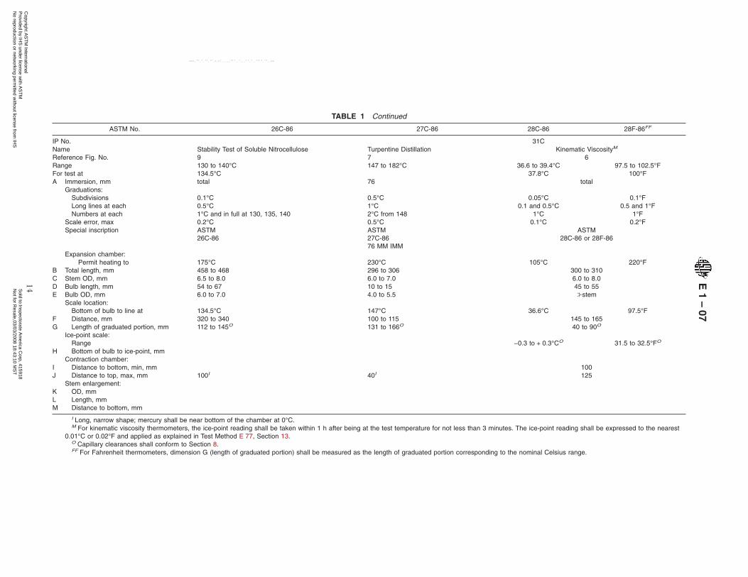
TABLE 1 Continued
ASTM No. 26C-86 27C-86 28C-86 28F-86FF
IP No. 31CName Stability Test of Soluble Nitrocellulose Turpentine Distillation Kinematic ViscosityM
Reference Fig. No. 9 7 6Range 130 to 140°C 147 to 182°C 36.6 to 39.4°C 97.5 to 102.5°FFor test at 134.5°C 37.8°C 100°FA Immersion, mm total 76 total
Graduations:Subdivisions 0.1°C 0.5°C 0.05°C 0.1°FLong lines at each 0.5°C 1°C 0.1 and 0.5°C 0.5 and 1°FNumbers at each 1°C and in full at 130, 135, 140 2°C from 148 1°C 1°F
Scale error, max 0.2°C 0.5°C 0.1°C 0.2°FSpecial inscription ASTM
26C-86ASTM27C-8676 MM IMM
ASTM28C-86 or 28F-86
Expansion chamber:Permit heating to 175°C 230°C 105°C 220°F
B Total length, mm 458 to 468 296 to 306 300 to 310C Stem OD, mm 6.5 to 8.0 6.0 to 7.0 6.0 to 8.0D Bulb length, mm 54 to 67 10 to 15 45 to 55E Bulb OD, mm 6.0 to 7.0 4.0 to 5.5 ≥stem
Scale location:Bottom of bulb to line at 134.5°C 147°C 36.6°C 97.5°F
F Distance, mm 320 to 340 100 to 115 145 to 165G Length of graduated portion, mm 112 to 145O 131 to 166O 40 to 90O
Ice-point scale:Range −0.3 to + 0.3°CO 31.5 to 32.5°FO
H Bottom of bulb to ice-point, mmContraction chamber:
I Distance to bottom, min, mm 100J Distance to top, max, mm 100I 40I 125
Stem enlargement:K OD, mmL Length, mmM Distance to bottom, mm
I Long, narrow shape; mercury shall be near bottom of the chamber at 0°C.M For kinematic viscosity thermometers, the ice-point reading shall be taken within 1 h after being at the test temperature for not less than 3 minutes. The ice-point reading shall be expressed to the nearest
0.01°C or 0.02°F and applied as explained in Test Method E 77, Section 13.O Capillary clearances shall conform to Section 8.FF For Fahrenheit thermometers, dimension G (length of graduated portion) shall be measured as the length of graduated portion corresponding to the nominal Celsius range.
E1
–07
14C
opyright AS
TM
International P
rovided by IHS
under license with A
ST
M
Sold to:Inspectorate A
merica C
orp, 415918N
ot for Resale,03/03/2008 18:43:10 M
ST
No reproduction or netw
orking permitted w
ithout license from IH
S
--``,,`,,,,``,`,,```,``,,,`````,-`-`,,`,,`,`,,`---

TABLE 1 Continued
ASTM No. 29C-86 29F-86FF 30F-86FF 33C-86 33F-86FF
IP No. 34C 20CName Kinematic ViscosityM Kinematic ViscosityM Low Aniline PointReference Fig. No. 6 6 3Range 52.6 to 55.4°C 127.5 to 132.5°F 207.5 to 212.5°F −38 to + 42°C −36.5 to + 107.5°FFor test at 54.4°C 130°F 210°FA Immersion, mm total total 50
Graduations:Subdivisions 0.05°C 0.1°F 0.1°F 0.2°C 0.5°FLong lines at each 0.1 and 0.5°C 0.5 and 1°F 0.5 and 1°F 1°C 1°FNumbers at each 1°C 1°F 1°F 2°C 5°F
Scale error, max 0.1°C 0.2°F 0.2°F 0.2°C 0.5°FSpecial inscription ASTM
29C-86 or 29F–86ASTM30F-86
ASTM33C-86 or 33F-86
50 MM IMMExpansion chamber:
Permit heating to 105°C 220°F 266°F 100°C 212°FB Total length, mm 300 to 310 300 to 310 415 to 425C Stem OD, mm 6.0 to 8.0 6.0 to 8.0 6.0 to 7.5D Bulb length, mm 45 to 55 45 to 55 10 to 20E Bulb OD, mm ≥stem ≥stem ≤5.0 and ≥stem
Scale location:Bottom of bulb to line at 52.6°C 127.5°F 207.5°F −35°C −31°F
F Distance, mm 145 to 165 145 to 165 100 to 125G Length of graduated portion, mm 40 to 90O 40 to 90O 240 to 280O
Ice-point scale:Range −0.3 to + 0.3°CO 31.5 to 32.5°FO 31.5 to 32.5°FO
H Bottom of bulb to ice-point, mmContraction chamber:
I Distance to bottom, min, mm 100 100J Distance to top, max, mm 125 125
Stem enlargement:K OD, mmL Length, mmM Distance to bottom, mm
M For kinematic viscosity thermometers, the ice-point reading shall be taken within 1 h after being at the test temperature for not less than 3 minutes. The ice-point reading shall be expressed to the nearest0.01°C or 0.02°F and applied as explained in Test Method E 77, Section 13.
O Capillary clearances shall conform to Section 8.FF For Fahrenheit thermometers, dimension G (length of graduated portion) shall be measured as the length of graduated portion corresponding to the nominal Celsius range.
E1
–07
15C
opyright AS
TM
International P
rovided by IHS
under license with A
ST
M
Sold to:Inspectorate A
merica C
orp, 415918N
ot for Resale,03/03/2008 18:43:10 M
ST
No reproduction or netw
orking permitted w
ithout license from IH
S
--``,,`,,,,``,`,,```,``,,,`````,-`-`,,`,,`,`,,`---

TABLE 1 Continued
ASTM No. 34C-86 34F-86FF 35C-86 35F-86FF 36C-86
IP No. 21C 59CName Medium Aniline Point High Aniline Point Titer TestN
Reference Fig. No. 3 7 3Range 25 to 105°C 77 to 221°F 90 to 170°C 194 to 338°F −2 to + 68°CFor test atA Immersion, mm 50 50 45
Graduations:Subdivisions 0.2°C 0.5°F 0.2°C 0.5°F 0.2°CLong lines at each 1°C 1°F 1°C 1°F 1°CNumbers at each 2°C 5°F 2°C 5°F 2°C
Scale error, max 0.2°C 0.5°F 0.4°C 1.0°F 0.2°CSpecial inscription ASTM
34C-86 or 34F-8650 MM IMM
ASTM35C-86 or 35F–86
50 MM IMM
ASTM36C-8645 MM IMM
Expansion chamber:Permit heating to 150°C 302°F 220°C 428°F 85°CO
B Total length, mm 415 to 425 415 to 425 400 to 410C Stem OD, mm 6.0 to 7.5 6.0 to 7.5 6.0 to 7.0Q
D Bulb length, mm 10 to 20 10 to 20 15 to 25E Bulb OD, mm ≤5.0 and ≥stem 5.0 to ≥stem ≤5.5 and ≥stem
Scale location:Bottom of bulb to line at 25°C 77°F 90°C 194°F −2°C
F Distance, mm 100 to 115 100 to 115 50 to 60G Length of graduated portion, mm 240 to 280O 240 to 280O 290 to 320O
Ice-point scale:Range
H Bottom of bulb to ice-point, mmContraction chamber:
I Distance to bottom, min, mmJ Distance to top, max, mm 35P
Stem enlargement:K OD, mmL Length, mmM Distance to bottom, mm
N Thermometers made to these specifications conform also with the requirements for the titer test thermometer of the American Oil Chemists Society and the Association of Official Agricultural Chemists, exceptfor the special inscription.
O Capillary clearances shall conform to Section 8.P Mercury shall be near middle of chamber at 0°C.Q The stem may be either the plain front or lens front type. If the thermometer is of the lens front type, the cross section of the stem shall be such that it will pass through an 8-mm ring gage but will not enter a
5-mm slot gage.FF For Fahrenheit thermometers, dimension G (length of graduated portion) shall be measured as the length of graduated portion corresponding to the nominal Celsius range.
E1
–07
16C
opyright AS
TM
International P
rovided by IHS
under license with A
ST
M
Sold to:Inspectorate A
merica C
orp, 415918N
ot for Resale,03/03/2008 18:43:10 M
ST
No reproduction or netw
orking permitted w
ithout license from IH
S
--``,,`,,,,``,`,,```,``,,,`````,-`-`,,`,,`,`,,`---
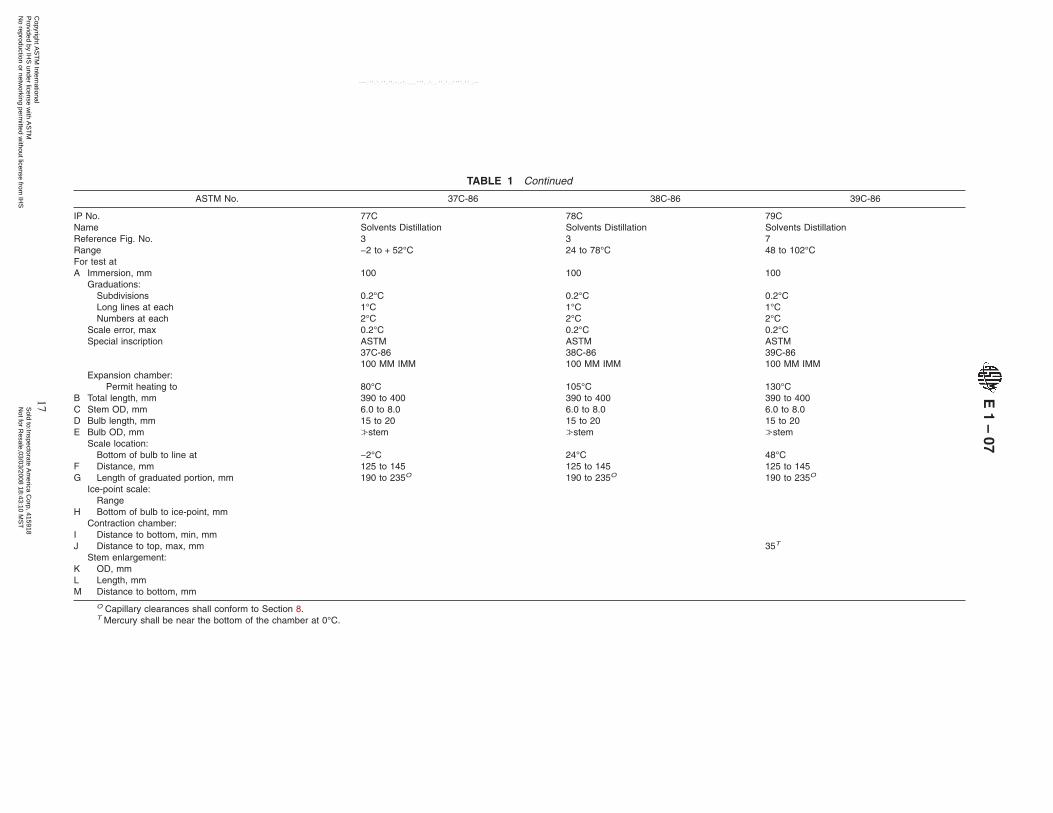
TABLE 1 Continued
ASTM No. 37C-86 38C-86 39C-86
IP No. 77C 78C 79CName Solvents Distillation Solvents Distillation Solvents DistillationReference Fig. No. 3 3 7Range −2 to + 52°C 24 to 78°C 48 to 102°CFor test atA Immersion, mm 100 100 100
Graduations:Subdivisions 0.2°C 0.2°C 0.2°CLong lines at each 1°C 1°C 1°CNumbers at each 2°C 2°C 2°C
Scale error, max 0.2°C 0.2°C 0.2°CSpecial inscription ASTM
37C-86100 MM IMM
ASTM38C-86100 MM IMM
ASTM39C-86100 MM IMM
Expansion chamber:Permit heating to 80°C 105°C 130°C
B Total length, mm 390 to 400 390 to 400 390 to 400C Stem OD, mm 6.0 to 8.0 6.0 to 8.0 6.0 to 8.0D Bulb length, mm 15 to 20 15 to 20 15 to 20E Bulb OD, mm ≥stem ≥stem ≥stem
Scale location:Bottom of bulb to line at −2°C 24°C 48°C
F Distance, mm 125 to 145 125 to 145 125 to 145G Length of graduated portion, mm 190 to 235O 190 to 235O 190 to 235O
Ice-point scale:Range
H Bottom of bulb to ice-point, mmContraction chamber:
I Distance to bottom, min, mmJ Distance to top, max, mm 35T
Stem enlargement:K OD, mmL Length, mmM Distance to bottom, mm
O Capillary clearances shall conform to Section 8.T Mercury shall be near the bottom of the chamber at 0°C.
E1
–07
17C
opyright AS
TM
International P
rovided by IHS
under license with A
ST
M
Sold to:Inspectorate A
merica C
orp, 415918N
ot for Resale,03/03/2008 18:43:10 M
ST
No reproduction or netw
orking permitted w
ithout license from IH
S
--``,,`,,,,``,`,,```,``,,,`````,-`-`,,`,,`,`,,`---

TABLE 1 Continued
ASTM No. 40C-86 41C-86 42C-86
IP No. 80C 81C 82CName Solvents Distillation Solvents Distillation Solvents DistillationReference Fig. No. 7 7 7Range 72 to 126°C 98 to 152°C 95 to 255°CFor test atA Immersion, mm 100 100 100
Graduations:Subdivisions 0.2°C 0.2°C 0.5°CLong lines at each 1°C 1°C 1°CNumbers at each 2°C 2°C 5°C
Scale error, max 0.2°C 0.3°C 1°CSpecial inscription ASTM ASTM ASTM
40C-86 41C-86 42C-86100 MM IMM 100 MM IMM 100 MM IMM
Expansion chamber:Permit heating to 150°C 180°C 280°C
B Total length, mm 390 to 400 390 to 400 390 to 400C Stem OD, mm 6.0 to 8.0 6.0 to 8.0 6.0 to 8.0D Bulb length, mm 15 to 20 15 to 20 15 to 20E Bulb OD, mm ≥stem ≥stem ≥stem
Scale location:Bottom of bulb to line at
F Distance, mm 72°C 98°C 95°CG Length of graduated portion, mm 125 to 145 125 to 145 125 to 145
190 to 235O 190 to 235O 190 to 235O
Ice-point scale:Range
H
I
Bottom of bulb to ice-point, mmContraction chamber:
Distance to bottom, min, mmJ Distance to top, max, mm 35T 35T 35T
Stem enlargement:K OD, mmL Length, mmM Distance to bottom, mm
O Capillary clearances shall conform to Section 8.T Mercury shall be near the bottom of the chamber at 0°C.
E1
–07
18C
opyright AS
TM
International P
rovided by IHS
under license with A
ST
M
Sold to:Inspectorate A
merica C
orp, 415918N
ot for Resale,03/03/2008 18:43:10 M
ST
No reproduction or netw
orking permitted w
ithout license from IH
S
--``,,`,,,,``,`,,```,``,,,`````,-`-`,,`,,`,`,,`---
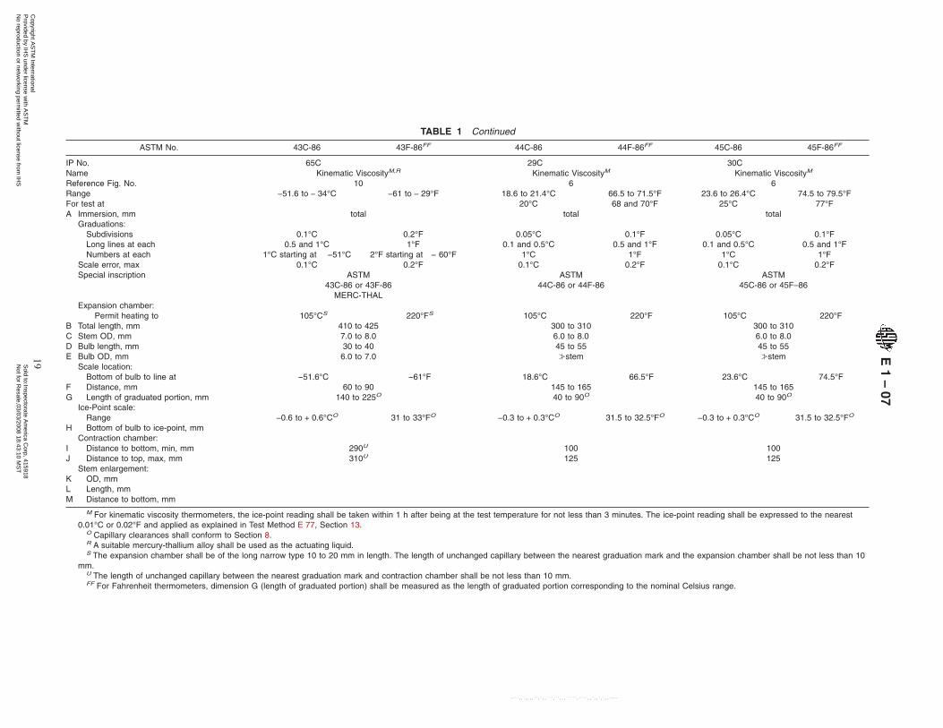
TABLE 1 Continued
ASTM No. 43C-86 43F-86FF 44C-86 44F-86FF 45C-86 45F-86FF
IP No. 65C 29C 30CName Kinematic ViscosityM,R Kinematic ViscosityM Kinematic ViscosityM
Reference Fig. No. 10 6 6Range −51.6 to − 34°C −61 to − 29°F 18.6 to 21.4°C 66.5 to 71.5°F 23.6 to 26.4°C 74.5 to 79.5°FFor test at 20°C 68 and 70°F 25°C 77°FA Immersion, mm
Graduations:total total total
SubdivisionsLong lines at each
0.1°C0.5 and 1°C
0.2°F1°F
0.05°C0.1 and 0.5°C
0.1°F0.5 and 1°F
0.05°C0.1 and 0.5°C
0.1°F0.5 and 1°F
Numbers at each 1°C starting at −51°C 2°F starting at − 60°F 1°C 1°F 1°C 1°FScale error, max 0.1°C 0.2°F 0.1°C 0.2°F 0.1°C 0.2°FSpecial inscription ASTM ASTM ASTM
43C-86 or 43F-86 44C-86 or 44F-86 45C-86 or 45F–86MERC-THAL
Expansion chamber:Permit heating to 105°CS 220°FS 105°C 220°F 105°C 220°F
B Total length, mm 410 to 425 300 to 310 300 to 310C Stem OD, mm 7.0 to 8.0 6.0 to 8.0 6.0 to 8.0D Bulb length, mm 30 to 40 45 to 55 45 to 55E Bulb OD, mm 6.0 to 7.0 ≥stem ≥stem
Scale location:Bottom of bulb to line at −51.6°C −61°F 18.6°C 66.5°F 23.6°C 74.5°F
F Distance, mm 60 to 90 145 to 165 145 to 165G Length of graduated portion, mm 140 to 225O 40 to 90O 40 to 90O
Ice-Point scale:Range −0.6 to + 0.6°CO 31 to 33°FO −0.3 to + 0.3°CO 31.5 to 32.5°FO −0.3 to + 0.3°CO 31.5 to 32.5°FO
H Bottom of bulb to ice-point, mmContraction chamber:
I Distance to bottom, min, mm 290U 100 100J Distance to top, max, mm 310U 125 125
Stem enlargement:K OD, mmL Length, mmM Distance to bottom, mm
M For kinematic viscosity thermometers, the ice-point reading shall be taken within 1 h after being at the test temperature for not less than 3 minutes. The ice-point reading shall be expressed to the nearest0.01°C or 0.02°F and applied as explained in Test Method E 77, Section 13.
O Capillary clearances shall conform to Section 8.R A suitable mercury-thallium alloy shall be used as the actuating liquid.S The expansion chamber shall be of the long narrow type 10 to 20 mm in length. The length of unchanged capillary between the nearest graduation mark and the expansion chamber shall be not less than 10
mm.U The length of unchanged capillary between the nearest graduation mark and contraction chamber shall be not less than 10 mm.FF For Fahrenheit thermometers, dimension G (length of graduated portion) shall be measured as the length of graduated portion corresponding to the nominal Celsius range.
E1
–07
19C
opyright AS
TM
International P
rovided by IHS
under license with A
ST
M
Sold to:Inspectorate A
merica C
orp, 415918N
ot for Resale,03/03/2008 18:43:10 M
ST
No reproduction or netw
orking permitted w
ithout license from IH
S
--``,,`,,,,``,`,,```,``,,,`````,-`-`,,`,,`,`,,`---

TABLE 1 Continued
ASTM No. 46C-86 46F-86FF 47C-86 47F-86FF 48C-86 48F-86FF
IP No. 66C 35C 90CNameReference Fig. No.
Kinematic ViscosityM
6Kinematic ViscosityM
6Kinematic ViscosityM
6RangeFor test at
48.6 to 51.4°C50°C
119.5 to 124.5°F122°F
58.6 to 61.4°C60°C
137.5 to 142.5°F140°F
80.6 to 83.4°C82.2°C
177.5 to 182.5°F180°F
A Immersion, mm total total totalGraduations:
SubdivisionsLong lines at eachNumbers at each
0.05°C0.1 and 0.5°C
1°C
0.1°F0.5 and 1°F
1°F
0.05°C0.1 and 0.5°C
1°C
0.1°F0.5 and 1°F
1°F
0.05°C0.1 and 0.5°C
1°C
0.1°F0.5 and 1°F
1°FScale error, max 0.1°C 0.2°F 0.1°C 0.2°F 0.1°C 0.2°FSpecial inscription ASTM
46C-86 or 46F–86ASTM
47C-86 or 47F–86ASTM
48C-86 or 48F–86Expansion chamber:
Permit heating to 105°C 220°F 105°C 220°F 105°C 220°FB Total length, mm 300 to 310 300 to 310 300 to 310C Stem OD, mm 6.0 to 8.0 6.0 to 8.0 6.0 to 8.0D Bulb length, mm 45 to 55 45 to 55 45 to 55E Bulb OD, mm ≥stem ≥stem ≥stem
Scale location:Bottom of bulb to line at 48.6°C 119.5°F 58.6°C 137.5°F 80.6°C 177.5°F
F Distance, mm 145 to 165 145 to 165 145 to 165G Length of graduated portion, mm 40 to 90O 40 to 90O 40 to 90O
Ice-point scale:Range −0.3 to + 0.3°CO 31.5 to 32.5°FO −0.3 to + 0.3°CO 31.5 to 32.5°FO −0.3 to + 0.3°CO 31.5 to 32.5°FO
H Bottom of bulb to ice-point, mmContraction chamber:
I Distance to bottom, min, mm 100 100 100J Distance to top, max, mm 125 125 125
KLM
Stem enlargement:OD, mmLength, mmDistance to bottom, mm
M For kinematic viscosity thermometers, the ice-point reading shall be taken within 1 h after being at the test temperature for not less than 3 minutes. The ice-point reading shall be expressed to the nearest0.01°C or 0.02°F and applied as explained in Test Method E 77, Section 13.
O Capillary clearances shall conform to Section 8.FF For Fahrenheit thermometers, dimension G (length of graduated portion) shall be measured as the length of graduated portion corresponding to the nominal Celsius range.
E1
–07
20C
opyright AS
TM
International P
rovided by IHS
under license with A
ST
M
Sold to:Inspectorate A
merica C
orp, 415918N
ot for Resale,03/03/2008 18:43:10 M
ST
No reproduction or netw
orking permitted w
ithout license from IH
S
--``,,`,,,,``,`,,```,``,,,`````,-`-`,,`,,`,`,,`---
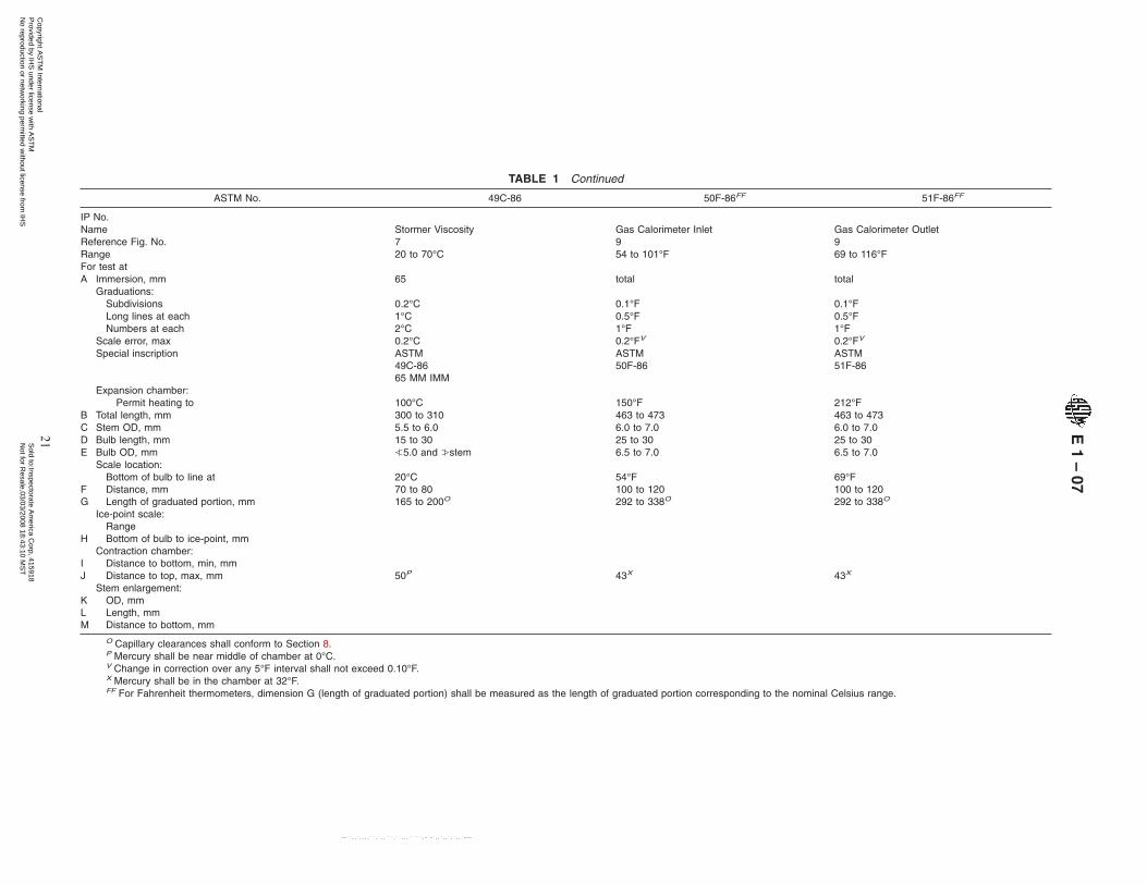
TABLE 1 Continued
ASTM No. 49C-86 50F-86FF 51F-86FF
IP No.Name Stormer Viscosity Gas Calorimeter Inlet Gas Calorimeter OutletReference Fig. No. 7 9 9Range 20 to 70°C 54 to 101°F 69 to 116°FFor test atA Immersion, mm 65 total total
Graduations:Subdivisions 0.2°C 0.1°F 0.1°FLong lines at each 1°C 0.5°F 0.5°FNumbers at each 2°C 1°F 1°F
Scale error, max 0.2°C 0.2°FV 0.2°FV
Special inscription ASTM49C-8665 MM IMM
ASTM50F-86
ASTM51F-86
Expansion chamber:Permit heating to 100°C 150°F 212°F
B Total length, mm 300 to 310 463 to 473 463 to 473C Stem OD, mm 5.5 to 6.0 6.0 to 7.0 6.0 to 7.0D Bulb length, mm 15 to 30 25 to 30 25 to 30E Bulb OD, mm ≤5.0 and ≥stem 6.5 to 7.0 6.5 to 7.0
Scale location:
FG
Bottom of bulb to line atDistance, mmLength of graduated portion, mm
20°C70 to 80165 to 200O
54°F100 to 120292 to 338O
69°F100 to 120292 to 338O
Ice-point scale:Range
H
I
Bottom of bulb to ice-point, mmContraction chamber:
Distance to bottom, min, mmJ Distance to top, max, mm 50P 43X 43X
KLM
Stem enlargement:OD, mmLength, mmDistance to bottom, mm
O Capillary clearances shall conform to Section 8.P Mercury shall be near middle of chamber at 0°C.V Change in correction over any 5°F interval shall not exceed 0.10°F.X Mercury shall be in the chamber at 32°F.FF For Fahrenheit thermometers, dimension G (length of graduated portion) shall be measured as the length of graduated portion corresponding to the nominal Celsius range.
E1
–07
21C
opyright AS
TM
International P
rovided by IHS
under license with A
ST
M
Sold to:Inspectorate A
merica C
orp, 415918N
ot for Resale,03/03/2008 18:43:10 M
ST
No reproduction or netw
orking permitted w
ithout license from IH
S
--``,,`,,,,``,`,,```,``,,,`````,-`-`,,`,,`,`,,`---

TABLE 1 Continued
ASTM No. 52C-86 54C-86 54F-86FF 56C-86 56F-86FF
IP No. 18CNameReference Fig. No.
Butadiene Boiling Point Range4
Congealing Point4
Bomb Calorimeter9
Range −10 to + 5°C 20 to 100.6°C 68 to 213°F 19 to 35°C 66 to 95°FFor test atA Immersion, mm total total total
Graduations:Subdivisions 0.1°C 0.2°C 0.5°F 0.02°C 0.05°FLong lines at each 0.5°C 1°C 1°F 0.1°C 0.1 and
0.5°FNumbers at each 1°C 2°C 5°F 0.2°C 1°F
Scale error, max 0.1°C 0.2°C 0.5°F 0.10°CY 0.20°FZ
Special inscription ASTM52C-86
ASTM54C–86 or 54F-86
ASTM56C–86 or 56F-86
Expansion chamber:Permit heating to 100°CW 110°C 230°F 66°C 150°F
B Total length, mm 157 to 167 305 to 315 570 to 600C Stem OD, mm 6.0 to 6.5 6.0 to 8.0 7.0 to 8.0D Bulb length, mm 9 to 13 10 to 12 35 to 55E Bulb OD, mm 5.5 to ≥stem 4.5 to 6.0MM 7.0 to 8.0BB
Scale location:Bottom of bulb to line at −10°C 20°C 68°F 19°C 66°F
F Distance, mm 28 to 36 60 to 70 165 to 187G Length of graduated portion, mm 70 to 100O 170 to 215O 323 to 385O
Ice-point scale:Range
H Bottom of bulb to ice-point, mmContraction chamber:
I Distance to bottom, min, mmJ Distance to top, max, mm 76
Stem enlargement:K OD, mmL Length, mmM Distance to bottom, mm
O Capillary clearances shall conform to Section 8.W Expansion chamber shall be of the long narrow type and there shall be not less than 10 mm of unchanged capillary between the base of the chamber and the top graduation.Y Over any interval of 2°C the change in correction shall not exceed 0.02°C.Z Over any interval of 4°F the change in correction shall not exceed 0.05°F.BB The bulb diameter shall not be more than 0.5 mm greater than the stem.FF For Fahrenheit thermometers, dimension G (length of graduated portion) shall be measured as the length of graduated portion corresponding to the nominal Celsius range.MM Bulb shape ellipsoidal (see Fig. 2).
E1
–07
22C
opyright AS
TM
International P
rovided by IHS
under license with A
ST
M
Sold to:Inspectorate A
merica C
orp, 415918N
ot for Resale,03/03/2008 18:43:10 M
ST
No reproduction or netw
orking permitted w
ithout license from IH
S
--``,,`,,,,``,`,,```,``,,,`````,-`-`,,`,,`,`,,`---
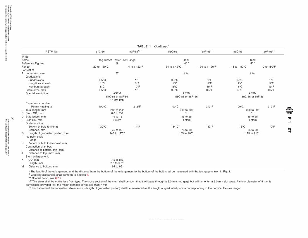
TABLE 1 Continued
ASTM No. 57C-86 57F-86FF 58C-86 58F-86FF 59C-86 59F-86FF
IP No.Name Tag Closed Tester Low Range Tank TankReference Fig. No. 5 4AA 4AA
Range −20 to + 50°C −4 to + 122°F −34 to + 49°C −30 to + 120°F −18 to + 82°C 0 to 180°FFor test atA Immersion, mm 57 total total
Graduations:Subdivisions 0.5°C 1°F 0.5°C 1°F 0.5°C 1°FLong lines at each 1°C 5°F 1°C 5°F 1°C 5°FNumbers at each 5°C 10°F 5°C 10°F 5°C 10°F
Scale error, max 0.5°C 1°F 0.3°C 0.5°F 0.3°C 0.5°FSpecial inscription ASTM
57C-86 or 57F-8657 MM IMM
ASTM58C-86 or 58F–86
ASTM59C-86 or 59F-86
Expansion chamber:Permit heating to 100°C 212°F 100°C 212°F 100°C 212°F
B Total length, mm 282 to 292 300 to 305 300 to 305C Stem OD, mm 6.0 to 7.0 CC CC
D Bulb length, mm 9 to 13 15 to 25 15 to 25E Bulb OD, mm ≥stem ≥stem ≥stem
Scale location:Bottom of bulb to line at −20°C −4°F −34°C −30°F −18°C 0°F
F Distance, mm 75 to 90 75 to 90 65 to 80G Length of graduated portion, mm 143 to 177O 165 to 205O 175 to 210O
Ice-point scaleRange
H
IJ
Bottom of bulb to ice-point, mmContraction chamber:
Distance to bottom, min, mmDistance to top, max, mm
Stem enlargement:KLM
OD, mmLength, mmDistance to bottom, mm
7.5 to 8.52.5 to 5.0E
64 to 66
E The length of the enlargement, and the distance from the bottom of the enlargement to the bottom of the bulb shall be measured with the test gage shown in Fig. 1.O Capillary clearances shall conform to Section 8.AA Special finish, see 6.2.2.CC The stem shall be of the lens front type. The cross section of the stem shall be such that it will pass through a 8.0-mm ring gage but will not enter a 5.0-mm slot gage. A minor diameter of 4 mm is
permissible provided that the major diameter is not less than 7 mm.FF For Fahrenheit thermometers, dimension G (length of graduated portion) shall be measured as the length of graduated portion corresponding to the nominal Celsius range.
E1
–07
23C
opyright AS
TM
International P
rovided by IHS
under license with A
ST
M
Sold to:Inspectorate A
merica C
orp, 415918N
ot for Resale,03/03/2008 18:43:10 M
ST
No reproduction or netw
orking permitted w
ithout license from IH
S
--``,,`,,,,``,`,,```,``,,,`````,-`-`,,`,,`,`,,`---

TABLE 1 Continued
ASTM No. 60C-86 60F-86FF 61C-86 61F-86FF 62C-86 62F-86FF
IP No. 63CNameReference Fig. No.
Tank4AA
Petrolatum Melting Point7
Precision4
Range 77 to 260°C 170 to 500°F 32 to 127°C 90 to 260°F −38 to + 2°C −36 to + 35°FFor test atA Immersion, mm total 79 total
Graduations:Subdivisions 1°C 2°F 0.2°C 0.5°F 0.1°C 0.2°FLong lines at each 5°C 10°F 1°C 1°F 0.5°C 1°FNumbers at each 10°C 20°F 2°C 5°F 1°C 2°F
Scale error, max 0.5°C 1°F 0.2°C 0.5°F 0.1°C 0.2°FSpecial inscription ASTM
60C-86 or 60F-86ASTM
61C-86 or 61F-8679 MM IMM
ASTM62C-86 or 62F-86
Expansion chamber:Permit heating to A 150°C 300°F 55°C 130°F
B Total length, mm 300 to 305 375 to 385 374 to 384C Stem OD, mm CC 6.0 to 8.0 7.0 to 8.0D Bulb length, mm 15 to 25 18 to 28DD 25 to 35E Bulb OD, mm ≥stem 5.0 to 6.0 6.0 to 7.0
Scale location:Bottom of bulb to line at 77°C 170°F 32°C 90°F −35°C −31°F
F Distance, mm 105 to 120 105 to 115 77 to 98G Length of graduated portion, mm 135 to 170O 200 to 240O 239 to 289O
Ice-point scale:Range
H Bottom of bulb to ice-point, mmContraction chamber:
IJ
Distance to bottom, min, mmDistance to top, max, mm 41
KLM
Stem enlargement:OD, mmLength, mmDistance to bottom, mm
A An expansion chamber is provided for relief of gas pressure to avoid distortion of the bulb at higher temperatures. It is not for the purpose of joining mercury separations and under no circumstances shouldthe thermometer be heated above the highest temperature reading.
O Capillary clearances shall conform to Section 8.AA Special finish, see 6.2.2.CC The stem shall be of the lens front type. The cross section of the stem shall be such that it will pass through a 8.0-mm ring gage but will not enter a 5.0-mm slot gage. A minor diameter of 4 mm is
permissible provided that the major diameter is not less than 7 mm.DD Bulb bottom shall be essentially hemispherical.FF For Fahrenheit thermometers, dimension G (length of graduated portion) shall be measured as the length of graduated portion corresponding to the nominal Celsius range.
E1
–07
24C
opyright AS
TM
International P
rovided by IHS
under license with A
ST
M
Sold to:Inspectorate A
merica C
orp, 415918N
ot for Resale,03/03/2008 18:43:10 M
ST
No reproduction or netw
orking permitted w
ithout license from IH
S
--``,,`,,,,``,`,,```,``,,,`````,-`-`,,`,,`,`,,`---
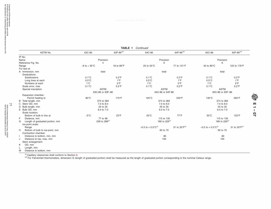
TABLE 1 Continued
ASTM No. 63C-86 63F-86FF 64C-86 64F-86FF 65C-86 65F-86FF
IP No.NameReference Fig. No.
Precision4
Precision6
Precision6
Range −8 to + 32°C 18 to 89°F 25 to 55°C 77 to 131°F 50 to 80°C 122 to 176°FFor test atA Immersion, mm total total total
Graduations:Subdivisions 0.1°C 0.2°F 0.1°C 0.2°F 0.1°C 0.2°FLong lines at each 0.5°C 1°F 0.5°C 1°F 0.5°C 1°FNumbers at each 1°C 2°F 1°C 2°F 1°C 2°F
Scale error, max 0.1°C 0.2°F 0.1°C 0.2°F 0.1°C 0.2°FSpecial inscription ASTM ASTM ASTM
63C-86 or 63F–86 64C-86 or 64F-86 65C-86 or 65F–86Expansion chamber:
Permit heating to 80°C 175°F 105°C 220°F 130°C 265°FB Total length, mm 374 to 384 374 to 384 374 to 384C Stem OD, mm 7.0 to 8.0 7.0 to 8.0 7.0 to 8.0D Bulb length, mm 25 to 35 25 to 35 25 to 35E Bulb OD, mm 6.0 to 7.0 6.0 to 7.0 6.0 to 7.0
Scale location:Bottom of bulb to line at −5°C 23°F 25°C 77°F 50°C 122°F
F Distance, mm 77 to 98 115 to 135 115 to 135G Length of graduated portion, mm 239 to 289O 189 to 229O 189 to 229O
Ice-point scale:Range −0.5 to + 0.5°CO 31 to 33°FO −0.5 to + 0.5°CO 31 to 33°FO
H Bottom of bulb to ice-point, mm 60 to 70 60 to 70Contraction chamber:
I Distance to bottom, min, mm 80 80J Distance to top, max, mm 100 100
KLM
Stem enlargement:OD, mmLength, mmDistance to bottom, mm
O Capillary clearances shall conform to Section 8.FF For Fahrenheit thermometers, dimension G (length of graduated portion) shall be measured as the length of graduated portion corresponding to the nominal Celsius range.
E1
–07
25C
opyright AS
TM
International P
rovided by IHS
under license with A
ST
M
Sold to:Inspectorate A
merica C
orp, 415918N
ot for Resale,03/03/2008 18:43:10 M
ST
No reproduction or netw
orking permitted w
ithout license from IH
S
--``,,`,,,,``,`,,```,``,,,`````,-`-`,,`,,`,`,,`---
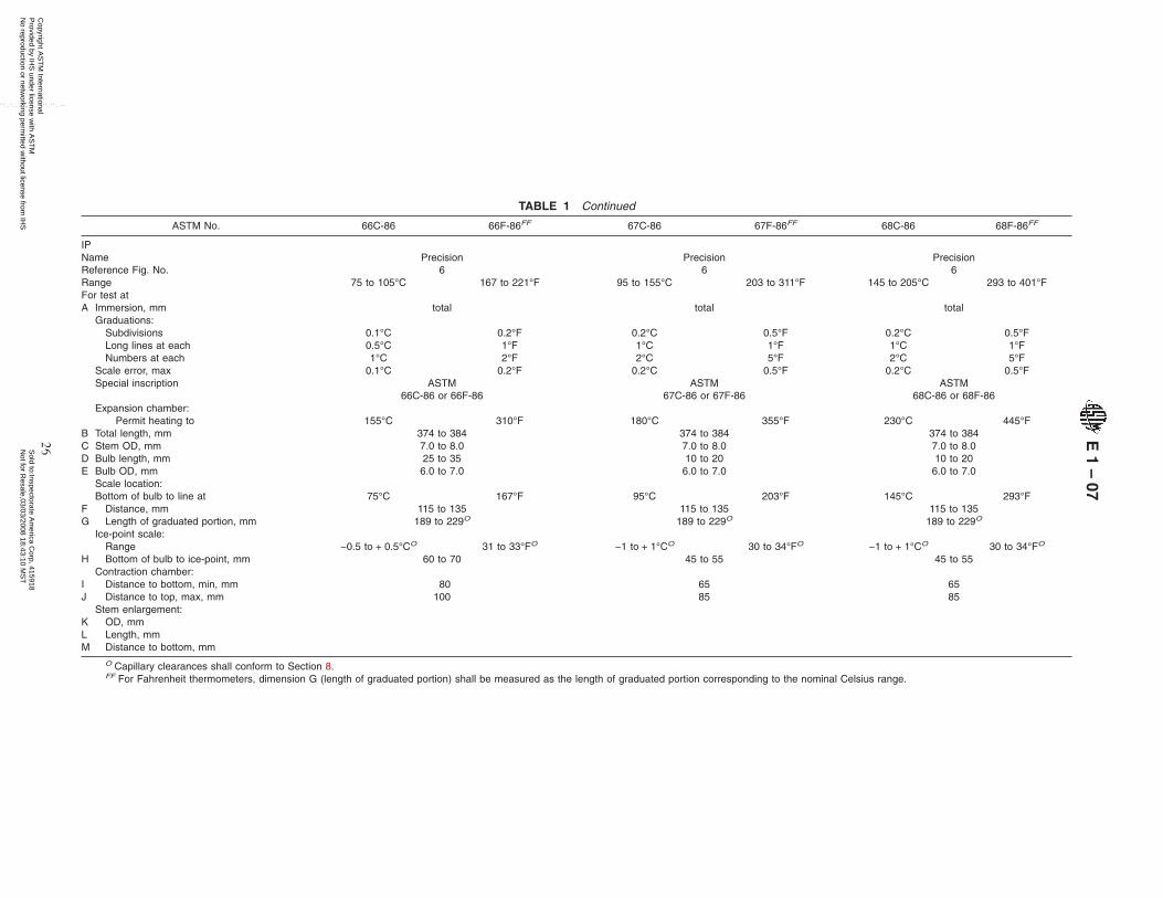
TABLE 1 Continued
ASTM No. 66C-86 66F-86FF 67C-86 67F-86FF 68C-86 68F-86FF
IPNameReference Fig. No.
Precision6
Precision6
Precision6
Range 75 to 105°C 167 to 221°F 95 to 155°C 203 to 311°F 145 to 205°C 293 to 401°FFor test atA Immersion, mm total total total
Graduations:Subdivisions 0.1°C 0.2°F 0.2°C 0.5°F 0.2°C 0.5°FLong lines at each 0.5°C 1°F 1°C 1°F 1°C 1°FNumbers at each 1°C 2°F 2°C 5°F 2°C 5°F
Scale error, max 0.1°C 0.2°F 0.2°C 0.5°F 0.2°C 0.5°FSpecial inscription ASTM
66C-86 or 66F-86ASTM
67C-86 or 67F-86ASTM
68C-86 or 68F-86Expansion chamber:
Permit heating to 155°C 310°F 180°C 355°F 230°C 445°FB Total length, mm 374 to 384 374 to 384 374 to 384C Stem OD, mm 7.0 to 8.0 7.0 to 8.0 7.0 to 8.0D Bulb length, mm 25 to 35 10 to 20 10 to 20E Bulb OD, mm 6.0 to 7.0 6.0 to 7.0 6.0 to 7.0
Scale location:Bottom of bulb to line at 75°C 167°F 95°C 203°F 145°C 293°F
F Distance, mm 115 to 135 115 to 135 115 to 135G Length of graduated portion, mm 189 to 229O 189 to 229O 189 to 229O
Ice-point scale:Range −0.5 to + 0.5°CO 31 to 33°FO −1 to + 1°CO 30 to 34°FO −1 to + 1°CO 30 to 34°FO
H Bottom of bulb to ice-point, mm 60 to 70 45 to 55 45 to 55Contraction chamber:
I Distance to bottom, min, mm 80 65 65J Distance to top, max, mm 100 85 85
Stem enlargement:K OD, mmL Length, mmM Distance to bottom, mm
O Capillary clearances shall conform to Section 8.FF For Fahrenheit thermometers, dimension G (length of graduated portion) shall be measured as the length of graduated portion corresponding to the nominal Celsius range.
E1
–07
26C
opyright AS
TM
International P
rovided by IHS
under license with A
ST
M
Sold to:Inspectorate A
merica C
orp, 415918N
ot for Resale,03/03/2008 18:43:10 M
ST
No reproduction or netw
orking permitted w
ithout license from IH
S
--``,,`,,,,``,`,,```,``,,,`````,-`-`,,`,,`,`,,`---
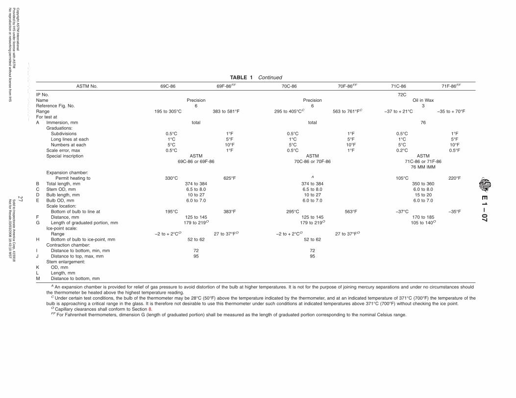
TABLE 1 Continued
ASTM No. 69C-86 69F-86FF 70C-86 70F-86FF 71C-86 71F-86FF
IP No. 72CNameReference Fig. No.
Precision6
Precision6
Oil in Wax3
Range 195 to 305°C 383 to 581°F 295 to 405°CC 563 to 761°FC −37 to + 21°C −35 to + 70°FFor test atA Immersion, mm total total 76
Graduations:Subdivisions 0.5°C 1°F 0.5°C 1°F 0.5°C 1°FLong lines at each 1°C 5°F 1°C 5°F 1°C 5°FNumbers at each 5°C 10°F 5°C 10°F 5°C 10°F
Scale error, max 0.5°C 1°F 0.5°C 1°F 0.2°C 0.5°FSpecial inscription ASTM
69C-86 or 69F-86ASTM
70C-86 or 70F-86ASTM
71C-86 or 71F-8676 MM IMM
Expansion chamber:Permit heating to 330°C 625°F A 105°C 220°F
B Total length, mm 374 to 384 374 to 384 350 to 360C Stem OD, mm 6.5 to 8.0 6.5 to 8.0 6.0 to 8.0D Bulb length, mm 10 to 27 10 to 27 15 to 20E Bulb OD, mm 6.0 to 7.0 6.0 to 7.0 6.0 to 7.0
Scale location:Bottom of bulb to line at 195°C 383°F 295°C 563°F −37°C −35°F
F Distance, mm 125 to 145 125 to 145 170 to 185G Length of graduated portion, mm 179 to 219O 179 to 219O 105 to 140O
Ice-point scale:Range −2 to + 2°CO 27 to 37°FO −2 to + 2°CO 27 to 37°FO
H Bottom of bulb to ice-point, mm 52 to 62 52 to 62Contraction chamber:
I Distance to bottom, min, mm 72 72J Distance to top, max, mm 95 95
Stem enlargement:K OD, mmL Length, mmM Distance to bottom, mm
A An expansion chamber is provided for relief of gas pressure to avoid distortion of the bulb at higher temperatures. It is not for the purpose of joining mercury separations and under no circumstances shouldthe thermometer be heated above the highest temperature reading.
C Under certain test conditions, the bulb of the thermometer may be 28°C (50°F) above the temperature indicated by the thermometer, and at an indicated temperature of 371°C (700°F) the temperature of thebulb is approaching a critical range in the glass. It is therefore not desirable to use this thermometer under such conditions at indicated temperatures above 371°C (700°F) without checking the ice point.
O Capillary clearances shall conform to Section 8.FF For Fahrenheit thermometers, dimension G (length of graduated portion) shall be measured as the length of graduated portion corresponding to the nominal Celsius range.
E1
–07
27C
opyright AS
TM
International P
rovided by IHS
under license with A
ST
M
Sold to:Inspectorate A
merica C
orp, 415918N
ot for Resale,03/03/2008 18:43:10 M
ST
No reproduction or netw
orking permitted w
ithout license from IH
S
--``,,`,,,,``,`,,```,``,,,`````,-`-`,,`,,`,`,,`---

TABLE 1 Continued
ASTM No. 72C-86 72F-86FF 73C-86 73F-86FF 74C-86 74F-86FF
IP No. 67C 68C 69CName Kinematic ViscosityM Kinematic ViscosityM,R Kinematic ViscosityM,R
Reference Fig. No. 10 10 10Range −19.4 to − 16.6°C −2.5 to + 2.5°F −41.4 to − 38.6°C −42.5 to − 37.5°F −55.4 to − 52.6°C −67.5 to − 62.5°FFor test at −17.8°C 0°F −40°C −40°F −53.9°C −65°FA Immersion, mm total total total
Graduations: 0.05°C 0.1°F 0.05°C 0.1°F 0.05°C 0.1°FLong lines at each 0.1 and 0.5°C 0.5 and 1°F 0.1 and 0.5°C 0.5 and 1°F 0.1 and 0.5°C 0.5 and 1°FNumbers at each 1°C 1°F 1°C 1°F 1°C 1°F
Scale error, max 0.1°C 0.2°F 0.1°C 0.2°F 0.1°C 0.2°FSpecial inscription ASTM
72C-86 or 72F-86ASTM
73C-86 or 73F-86MERC-THAL
ASTM74C-86 or 74F-86
MERC-THALExpansion chamber:
Permit heating to 105°C 220°F 105°C 220°F 105°C 220°FB Total length, mm 300 to 310 300 to 310 300 to 310C Stem OD, mm 6.0 to 8.0 6.0 to 8.0 6.0 to 8.0D Bulb length, mm 45 to 55 45 to 55 45 to 55E Bulb OD, mm ≥stem ≥stem ≥stem
Scale location:Bottom of bulb to line at −19.4°C −2.5°F −41.4°C −42.5°F −55.4°C −67.5°F
F Distance, mm 80 to 110 80 to 110 80 to 110G Length of graduated portion, mm 40 to 90O 40 to 90O 40 to 90O
Ice-point scale:Range −0.3 to + 0.3°CO 31.5 to 32.5°FO −0.3 to + 0.3°CO 31.5 to 32.5°FO −0.3 to + 0.3°CO 31.5 to 32.5°FO
H Bottom of bulb to ice-point, mmContraction chamber:
I Distance to bottom, min, mm 180 180 180J Distance to top, max, mm 205 205 205
Stem enlargement:K OD, mmL Length, mmM Distance to bottom, mm
O Capillary clearances shall conform to Section 8.M For kinematic viscosity thermometers, the ice-point reading shall be taken within 1 h after being at the test temperature for not less than 3 minutes. The ice-point reading shall be expressed to the nearest
0.01°C or 0.02°F and applied as explained in Test Method E 77, Section 13.R A suitable mercury-thallium alloy shall be used as the actuating liquid.FF For Fahrenheit thermometers, dimension G (length of graduated portion) shall be measured as the length of graduated portion corresponding to the nominal Celsius range.
E1
–07
28C
opyright AS
TM
International P
rovided by IHS
under license with A
ST
M
Sold to:Inspectorate A
merica C
orp, 415918N
ot for Resale,03/03/2008 18:43:10 M
ST
No reproduction or netw
orking permitted w
ithout license from IH
S
--``,,`,,,,``,`,,```,``,,,`````,-`-`,,`,,`,`,,`---

TABLE 1 Continued
ASTM No. 75F-86FF 76F-86FF 77F-86FF
IP No.Name Coolant (Antifreeze) Freezing Point Coolant (Antifreeze) Freezing PointR Saybolt ViscosityReference Fig. No. 3 3 8Range −35 to + 35°F −65 to + 5°F 245 to 265°FFor test at 250°FG
A Immersion, mm 100 100 totalGraduations:
Subdivisions 0.5°F 0.5°F 0.5°FLong lines at each 1°F 1°F 1°FNumbers at each 5°F 5°F 5°F
Scale error, max 0.5°F 1°F 0.5°FSpecial inscription ASTM
75F-86100 MM IMM
ASTM76F-86100 MM IMMMERC-THAL
ASTM77F-86
Expansion chamber:Permit heating to 140°F 140°F 315°F
B Total length, mm 403 to 413 403 to 413 270 to 280C Stem OD, mm 6.0 to 7.0 6.0 to 7.0 6.0 to 7.0D Bulb length, mm 20 to 30 20 to 30 25 to 35E Bulb OD, mm 5.0 to 6.0 5.0 to 6.0 <5.0 and >stem
Scale location:Bottom of bulb to line at −35°F −65°F 245°F
F Distance, mm 200 to 230 200 to 230 135 to 150G Length of graduated portion, mm 116 to 162O 116 to 162O 67 to 101O
Ice-point scale:Range
H Bottom of bulb to ice-point, mmContraction chamber:
I Distance to bottom, min, mmJ Distance to top, max, mm 60H
Stem enlargement:K OD, mm 8.0 to 10.0L Length, mm 4.0 to 7.0M Distance to bottom, mm 112 to 116
G The test temperature shall be indicated by an arrow whether the graduation corresponding to that point is numbered or not.H Long, narrow shape; mercury shall be in the chamber at 0°C (32°F).O Capillary clearances shall conform to Section 8.R A suitable mercury-thallium alloy shall be used as the actuating liquid.FF For Fahrenheit thermometers, dimension G (length of graduated portion) shall be measured as the length of graduated portion corresponding to the nominal Celsius range.
E1
–07
29C
opyright AS
TM
International P
rovided by IHS
under license with A
ST
M
Sold to:Inspectorate A
merica C
orp, 415918N
ot for Resale,03/03/2008 18:43:10 M
ST
No reproduction or netw
orking permitted w
ithout license from IH
S
--``,,`,,,,``,`,,```,``,,,`````,-`-`,,`,,`,`,,`---
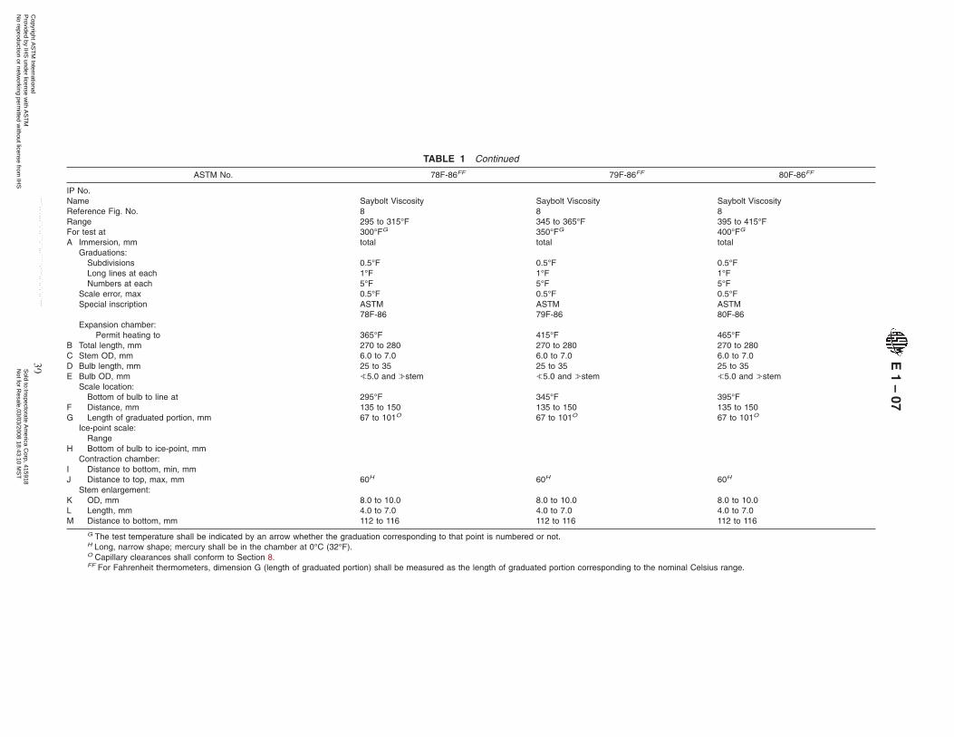
TABLE 1 Continued
ASTM No. 78F-86FF 79F-86FF 80F-86FF
IP No.Name Saybolt Viscosity Saybolt Viscosity Saybolt ViscosityReference Fig. No. 8 8 8Range 295 to 315°F 345 to 365°F 395 to 415°FFor test at 300°FG 350°FG 400°FG
A Immersion, mm total total totalGraduations:
Subdivisions 0.5°F 0.5°F 0.5°FLong lines at each 1°F 1°F 1°FNumbers at each 5°F 5°F 5°F
Scale error, max 0.5°F 0.5°F 0.5°FSpecial inscription ASTM
78F-86ASTM79F-86
ASTM80F-86
Expansion chamber:Permit heating to 365°F 415°F 465°F
B Total length, mm 270 to 280 270 to 280 270 to 280C Stem OD, mm 6.0 to 7.0 6.0 to 7.0 6.0 to 7.0D Bulb length, mm 25 to 35 25 to 35 25 to 35E Bulb OD, mm ≤5.0 and ≥stem ≤5.0 and ≥stem ≤5.0 and ≥stem
Scale location:Bottom of bulb to line at 295°F 345°F 395°F
F Distance, mm 135 to 150 135 to 150 135 to 150G Length of graduated portion, mm 67 to 101O 67 to 101O 67 to 101O
Ice-point scale:Range
H Bottom of bulb to ice-point, mmContraction chamber:
I Distance to bottom, min, mmJ Distance to top, max, mm 60H 60H 60H
Stem enlargement:K OD, mm 8.0 to 10.0 8.0 to 10.0 8.0 to 10.0L Length, mm 4.0 to 7.0 4.0 to 7.0 4.0 to 7.0M Distance to bottom, mm 112 to 116 112 to 116 112 to 116
G The test temperature shall be indicated by an arrow whether the graduation corresponding to that point is numbered or not.H Long, narrow shape; mercury shall be in the chamber at 0°C (32°F).O Capillary clearances shall conform to Section 8.FF For Fahrenheit thermometers, dimension G (length of graduated portion) shall be measured as the length of graduated portion corresponding to the nominal Celsius range.
E1
–07
30C
opyright AS
TM
International P
rovided by IHS
under license with A
ST
M
Sold to:Inspectorate A
merica C
orp, 415918N
ot for Resale,03/03/2008 18:43:10 M
ST
No reproduction or netw
orking permitted w
ithout license from IH
S
--``,,`,,,,``,`,,```,``,,,`````,-`-`,,`,,`,`,,`---

TABLE 1 Continued
ASTM No. 81F-86FF 82C-86 82F-86FF 83C-03 83F-03FF
IP No.Name Saybolt Viscosity Fuel Rating Engine Fuel Rating Air-LowReference Fig. No. 8 11 11Range 445 to 465°F −15 to + 105°C 0 to 220°F 15 to 70°C 60 to 160°FFor test at 450°FG 51.7°C and 65.6°CG 125°Fand
150°FG
A Immersion, mm total 30EE 40EE
Graduations:Subdivisions 0.5°F 1°C 2°F 1°C 1°FLong lines at each 1°F 5°C 10°F 5°C 5°FNumbers at each 5°F 10°C 20°F 10°C 10°F
Scale error, max 0.5°F 1°C 2°F 1°C 2°FSpecial inscription ASTM ASTM ASTM
81F-86 82C-86 or 82F-86 83C-03 or 83F-0330 MM IMM 40 MM IMM
Expansion chamber:Permit heating to 515°F 125°C 260°F 100°C 215°F
B Total length, mm 270 to 280 159 to 165 168 to 174C Stem OD, mm 6.0 to 7.0 6.0 to 7.0 6.0 to 7.0D Bulb length, mm 25 to 35 6 to 11 6 to 11E Bulb OD, mm ≤5.0 and ≥stem 5.0 to 6.5 5.0 to 6.5
Scale location:Bottom of bulb to line at 445°F −15°C 0°F 15°C 60°F
F Distance, mm 135 to 150 62 to 70 71 to 78G Length of graduated portion, mm 67 to 101O 65 to 81O 64 to 81O
Ice-point scale:Range
H Bottom of bulb to ice-point, mmContraction chamber:
I Distance to bottom, min, mmJ Distance to top, max, mm 60H
Stem enlargement:K OD, mm 8.0 to 10.0 8.0 to 9.0 8.0 to 9.0L Length, mm 4.0 to 7.0M Distance to bottom, mm 112 to 116 28 to 32 38 to 42
G The test temperature shall be indicated by an arrow whether the graduation corresponding to that point is numbered or not.H Long, narrow shape; mercury shall be in the chamber at 0°C (32°F).O Capillary clearances shall conform to Section 8.EE Immersion line shall be omitted.FF For Fahrenheit thermometers, dimension G (length of graduated portion) shall be measured as the length of graduated portion corresponding to the nominal Celsius range.
E1
–07
31C
opyright AS
TM
International P
rovided by IHS
under license with A
ST
M
Sold to:Inspectorate A
merica C
orp, 415918N
ot for Resale,03/03/2008 18:43:10 M
ST
No reproduction or netw
orking permitted w
ithout license from IH
S
--``,,`,,,,``,`,,```,``,,,`````,-`-`,,`,,`,`,,`---

TABLE 1 Continued
ASTM No. 84C-86 84F-86FF 85C-86 85F-86FF 86C-86 86F-86FF
IP No.Name Fuel Rating, Orifice Tank Fuel Rating, Surge Fuel Rating, MixReference Fig. No. 11 11 8Range 25 to 80°C 75 to 175°F 40 to 150°C 100 to 300°F 95 to 175°C 200 to 350°FFor test at 51.7°CG 125°FG 107.2°CG 225°FG 104.4°C and 220°F and
148.9°CG 300°FG
A Immersion, mm 249EE 181EE 35EE
Graduations:Subdivisions 1°C 1°F 1°C 2°F 1°C 2°FLong lines at each 5°C 5°F 5°C 10°F 5°C 10°FNumbers at each 10°C 10°F 10°C 20°F 10°C 20°F
Scale error, max 1°C 2°F 1°C 2°F 1°C 2°FSpecial inscription ASTM
84C-86 or 84F-86249 MM IMM
ASTM85C-86 or 85F-86
181 MM IMM
ASTM86C-86 or 86F-86
35 MM IMMExpansion chamber:
Permit heating to 100°C 215°F 170°C 340°F 195°C 390°FB Total length, mm 378 to 387 305 to 314 164 to 170C Stem OD, mm 6.0 to 7.0 6.0 to 7.0 6.0 to 7.0D Bulb length, mm 6 to 11 6 to 11 6 to 11E Bulb OD, mm 5.0 to 6.5 5.0 to 6.5 5.0 to 6.5
Scale location:Bottom of bulb to line at 25°C 75°F 40°C 100°F 95°C 200°F
FG
Distance, mmLength of graduated portion, mm
284 to 29262 to 79O
213 to 22154 to 77O
67 to 7558 to 81O
Ice-point scale:Range
H Bottom of bulb to ice-point, mmContraction chamber:
I Distance to bottom, min, mmJ Distance to top, max, mm 22
Stem enlargement:K OD, mm 8.0 to 9.0 8.0 to 9.0 8.0 to 9.0L Length, mmM Distance to bottom, mm 247 to 251 179 to 183 33 to 37
O Capillary clearances shall conform to Section 8.EE Immersion line shall be omitted.FF For Fahrenheit thermometers, dimension G (length of graduated portion) shall be measured as the length of graduated portion corresponding to the nominal Celsius range.
E1
–07
32C
opyright AS
TM
International P
rovided by IHS
under license with A
ST
M
Sold to:Inspectorate A
merica C
orp, 415918N
ot for Resale,03/03/2008 18:43:10 M
ST
No reproduction or netw
orking permitted w
ithout license from IH
S
--``,,`,,,,``,`,,```,``,,,`````,-`-`,,`,,`,`,,`---

TABLE 1 Continued
ASTM No. 87C-86 87F-86FF 88C-86 88F-86FF 89C-86
IP No.Name Fuel Rating Coolant Vegetable Oil Flash Solidification PointReference Fig. No. 8 5 3Range 150 to 205°C 300 to 400°F 10 to 200°C 50 to 392°F −20 to + 10°CFor test at 190.6°CG 375°FG
A Immersion, mm 40EE 57 76Graduations:
Subdivisions 1°C 1°F 1°C 2°F 0.1°CLong lines at each 5°C 5°F 5°C 10°F 0.5°CNumbers at each 10°C 10°F 10°C 20°F 1.0°C
Scale error, max 1°C 2°F 1°C 2°F 0.1°CSpecial inscription ASTM
87C-86 or 87F-8640 MM IMM
ASTM88C-86 or 88F-86
57 MM IMM
ASTM89C-8676 MM IMM
Expansion chamber:Permit heating to 225°C 440°F 250°C 490°F 60°C
B Total length, mm 169 to 175 282 to 292 365 to 375C Stem OD, mm 6.0 to 7.0 6.0 to 7.0 6.0 to 7.0D Bulb length, mm 6 to 11 9 to 13 18 to 28E Bulb OD, mm 5.0 to 6.5 ≥stem ≤5.0 and ≥stem
Scale location:Bottom of bulb to line at 150°C 300°F 10°C 50°F −20°C
FG
Distance, mmLength of graduated portion, mm
72 to 8059 to 82O
75 to 90143 to 177O
116 to 130185 to 219O
Ice-point scale:Range
H Bottom of bulb to ice-point, mmContraction chamber:
I Distance to bottom, min, mmJ Distance to top, max, mm 21
Stem enlargement:K OD, mm 8.0 to 9.0 7.5 to 8.5E
L Length, mm 2.5 to 5.0M Distance to bottom, mm 38 to 42 64 to 66
E The length of the enlargement, and the distance from the bottom of the enlargement to the bottom of the bulb shall be measured with the test gage shown in Fig. 1.O Capillary clearances shall conform to Section 8.EE Immersion line shall be omitted.FF For Fahrenheit thermometers, dimension G (length of graduated portion) shall be measured as the length of graduated portion corresponding to the nominal Celsius range.
E1
–07
33C
opyright AS
TM
International P
rovided by IHS
under license with A
ST
M
Sold to:Inspectorate A
merica C
orp, 415918N
ot for Resale,03/03/2008 18:43:10 M
ST
No reproduction or netw
orking permitted w
ithout license from IH
S
--``,,`,,,,``,`,,```,``,,,`````,-`-`,,`,,`,`,,`---
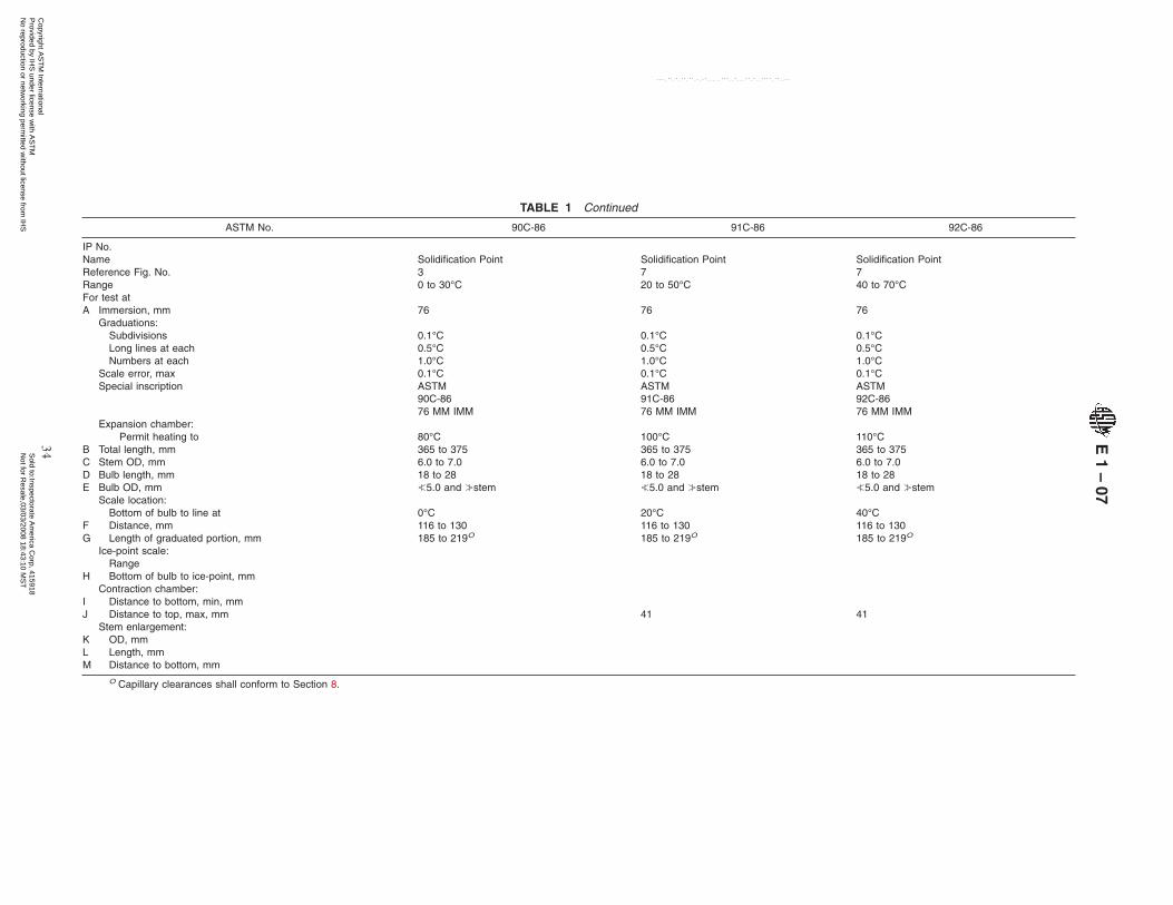
TABLE 1 Continued
ASTM No. 90C-86 91C-86 92C-86
IP No.Name Solidification Point Solidification Point Solidification PointReference Fig. No. 3 7 7Range 0 to 30°C 20 to 50°C 40 to 70°CFor test atA Immersion, mm 76 76 76
Graduations:Subdivisions 0.1°C 0.1°C 0.1°CLong lines at each 0.5°C 0.5°C 0.5°CNumbers at each 1.0°C 1.0°C 1.0°C
Scale error, max 0.1°C 0.1°C 0.1°CSpecial inscription ASTM
90C-86ASTM91C-86
ASTM92C-86
76 MM IMM 76 MM IMM 76 MM IMMExpansion chamber:
Permit heating to 80°C 100°C 110°CB Total length, mm 365 to 375 365 to 375 365 to 375C Stem OD, mm 6.0 to 7.0 6.0 to 7.0 6.0 to 7.0D Bulb length, mm 18 to 28 18 to 28 18 to 28E Bulb OD, mm ≤5.0 and ≥stem ≤5.0 and ≥stem ≤5.0 and ≥stem
Scale location:Bottom of bulb to line at 0°C 20°C 40°C
F Distance, mm 116 to 130 116 to 130 116 to 130G Length of graduated portion, mm 185 to 219O 185 to 219O 185 to 219O
Ice-point scale:Range
H Bottom of bulb to ice-point, mmContraction chamber:
I Distance to bottom, min, mmJ Distance to top, max, mm 41 41
Stem enlargement:K OD, mmL Length, mmM Distance to bottom, mm
O Capillary clearances shall conform to Section 8.
E1
–07
34C
opyright AS
TM
International P
rovided by IHS
under license with A
ST
M
Sold to:Inspectorate A
merica C
orp, 415918N
ot for Resale,03/03/2008 18:43:10 M
ST
No reproduction or netw
orking permitted w
ithout license from IH
S
--``,,`,,,,``,`,,```,``,,,`````,-`-`,,`,,`,`,,`---

TABLE 1 Continued
ASTM No. 93C-86 94C-86 95C-86
IP No.Name Solidification Point Solidification Point Solidification PointReference Fig. No. 7 7 7Range 60 to 90°C 80 to 110°C 100 to 130°CFor test atA Immersion, mm 76 76 76
Graduations:Subdivisions 0.1°C 0.1°C 0.1°CLong lines at each 0.5°C 0.5°C 0.5°CNumbers at each 1.0°C 1.0°C 1.0°C
Scale error, max 0.1°C 0.1°C 0.2°CSpecial inscription ASTM ASTM ASTM
93C-86 94C-86 95C-8676 MM IMM 76 MM IMM 76 MM IMM
Expansion chamber:Permit heating to 130°C 150°C 170°C
B Total length, mm 365 to 375 365 to 375 365 to 375C Stem OD, mm 6.0 to 7.0 6.0 to 7.0 6.0 to 7.0D Bulb length, mm 18 to 28 18 to 28 18 to 28E Bulb OD, mm ≤5.0 and ≥stem ≤5.0 and ≥stem ≤5.0 and ≥stem
Scale location:Bottom of bulb to line at 60°C 80°C 100°C
F Distance, mm 116 to 130 116 to 130 116 to 130G Length of graduated portion, mm 185 to 219O 185 to 219O 185 to 219O
Ice-point scale:Range
H Bottom of bulb to ice-point, mmContraction chamber:
I Distance to bottom, min, mmJ Distance to top, max, mm 41 41 41
Stem enlargement:K OD, mmL Length, mmM Distance to bottom, mm
O Capillary clearances shall conform to Section 8.
E1
–07
35C
opyright AS
TM
International P
rovided by IHS
under license with A
ST
M
Sold to:Inspectorate A
merica C
orp, 415918N
ot for Resale,03/03/2008 18:43:10 M
ST
No reproduction or netw
orking permitted w
ithout license from IH
S
--``,,`,,,,``,`,,```,``,,,`````,-`-`,,`,,`,`,,`---
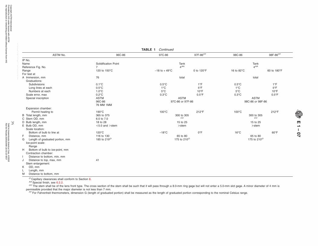
TABLE 1 Continued
ASTM No. 96C-86 97C-86 97F-86FF 98C-86 98F-86FF
IP No.Name Solidification Point Tank TankReference Fig. No. 7 4AA 4AA
Range 120 to 150°C −18 to + 49°C 0 to 120°F 16 to 82°C 60 to 180°FFor test atA Immersion, mm 76 total total
Graduations:Subdivisions 0.1°C 0.5°C 1°F 0.5°C 1°FLong lines at each 0.5°C 1°C 5°F 1°C 5°FNumbers at each 1.0°C 5°C 10°F 5°C 10°F
Scale error, max 0.2°C 0.3°C 0.5°F 0.3°C 0.5°FSpecial inscription ASTM
96C-8676 MM 1MM
ASTM97C-86 or 97F-86
ASTM98C-86 or 98F-86
Expansion chamber:Permit heating to 190°C 100°C 212°F 100°C 212°F
B Total length, mm 365 to 375 300 to 305 300 to 305C Stem OD, mm 6.0 to 7.0 CC CC
D Bulb length, mm 18 to 28 15 to 25 15 to 25E Bulb OD, mm ≤5.0 and ≥stem ≥stem ≥stem
Scale location:Bottom of bulb to line at 120°C −18°C 0°F 16°C 60°F
F Distance, mm 116 to 130 65 to 80 65 to 80G Length of graduated portion, mm 185 to 219O 175 to 210O 175 to 210O
Ice-point scale:Range
H Bottom of bulb to ice-point, mmContraction chamber:
I Distance to bottom, min, mmJ Distance to top, max, mm 41
Stem enlargement:K OD, mmL Length, mmM Distance to bottom, mm
O Capillary clearances shall conform to Section 8.AA Special finish, see 6.2.2.CC The stem shall be of the lens front type. The cross section of the stem shall be such that it will pass through a 8.0-mm ring gage but will not enter a 5.0-mm slot gage. A minor diameter of 4 mm is
permissible provided that the major diameter is not less than 7 mm.FF For Fahrenheit thermometers, dimension G (length of graduated portion) shall be measured as the length of graduated portion corresponding to the nominal Celsius range.
E1
–07
36C
opyright AS
TM
International P
rovided by IHS
under license with A
ST
M
Sold to:Inspectorate A
merica C
orp, 415918N
ot for Resale,03/03/2008 18:43:10 M
ST
No reproduction or netw
orking permitted w
ithout license from IH
S
--``,,`,,,,``,`,,```,``,,,`````,-`-`,,`,,`,`,,`---

TABLE 1 Continued
ASTM No. 99C-92 99F-86FF 100C-86 101C-86
IP No.Name Weathering TestR Solidification Point Solidification PointReference Fig. No. 3AA 7 7Range −50 to + 5°C −58 to + 41°F 145 to 205°C 195 to 305°CFor test atA Immersion, mm 35GG 76 76
Graduations:Subdivisions 0.2°C 0.5°F 0.2°C 0.5°CLong lines at each 1°C 1°F 1°C 1°CNumbers at each 2°C 5°F 2°C 5°C
Scale error, max 0.2°C 0.4°F 0.4°C 1.0°CSpecial inscription ASTM ASTM ASTM
99C-92 or 99F–86 100C-86 101C–8635 MM IMM 76 MM IMM 76 MM IMMMERC-THAL
Expansion chamber:Permit heating to Elongated type Elongated type 150°F 250°C 330°C
66°CB Total length, mm 299 to 305 365 to 375 365 to 375C Stem OD, mm 6.5 to 8.0HH 6.0 to 7.0 6.0 to 7.0D Bulb length, mm 15 to 20 18 to 28 18 to 28E Bulb OD, mm 6.0 to 7.0 ≤5.0 and ≥stem ≤5.0 and ≥stem
Scale location:Bottom of bulb to line at −50°C −58°F 145°C 195°C
F Distance, mm 50 to 75 116 to 130 116 to 130G Length of graduated portion, mm 169 to 215O 185 to 219O 185 to 219O
Ice-point scale:Range
H Bottom of bulb to ice-point, mmI Contraction chamber:
Distance to bottom, min, mmJ Distance to top, max, mm 41 41K Stem enlargement:
OD, mmL Length, mmM Distance to bottom, mm
O Capillary clearances shall conform to Section 8.R A suitable mecury-thallium alloy shall be used as the actuating liquid.AA Special finish, see 6.2.2.FF For Fahrenheit thermometers, dimension G (length of graduated portion) shall be measured as the length of graduated portion corresponding to the nominal Celsius range.GG The immersion line shall be visible in the case opening after assembly. The immersion shall be measured from the bottom of the bulb rather than from the bottom of the armor. See 6.2.2.HH The stem shall be either the round or lens-front type.
E1
–07
37C
opyright AS
TM
International P
rovided by IHS
under license with A
ST
M
Sold to:Inspectorate A
merica C
orp, 415918N
ot for Resale,03/03/2008 18:43:10 M
ST
No reproduction or netw
orking permitted w
ithout license from IH
S
--``,,`,,,,``,`,,```,``,,,`````,-`-`,,`,,`,`,,`---
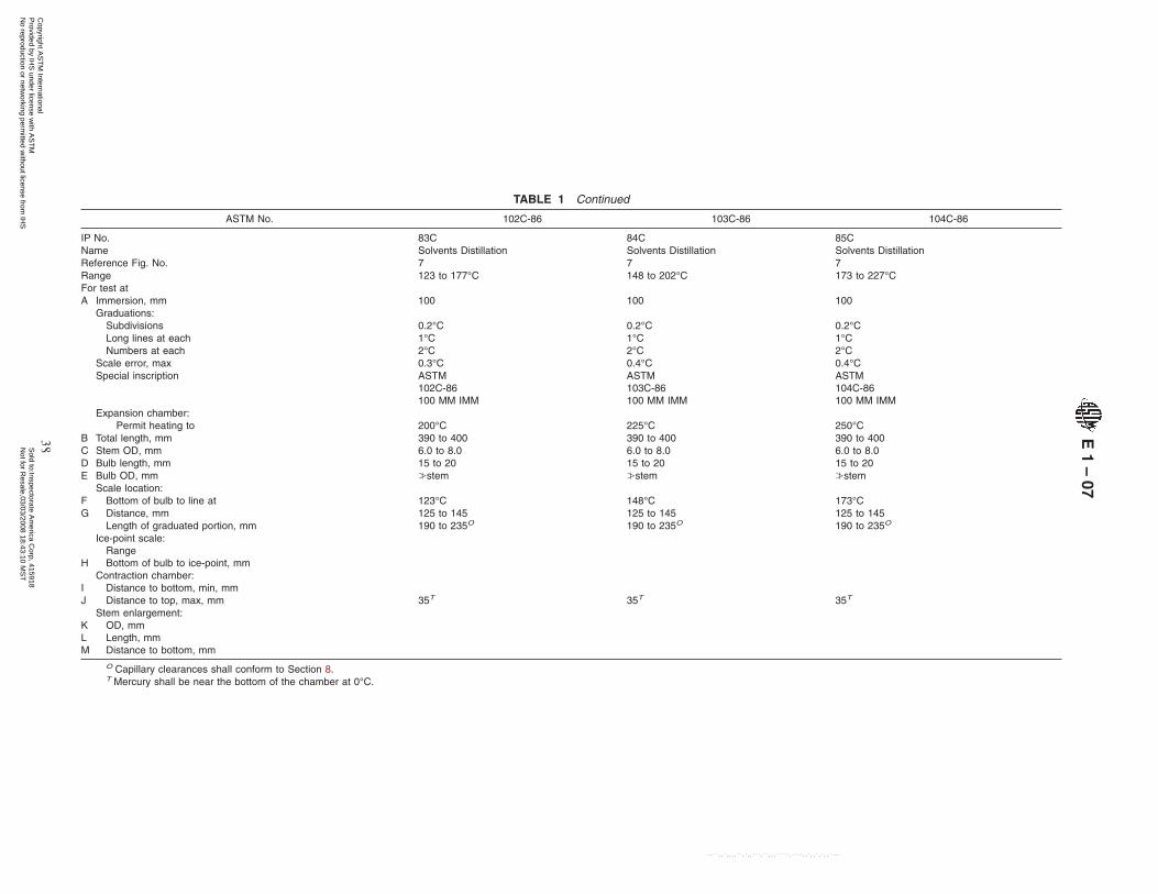
TABLE 1 Continued
ASTM No. 102C-86 103C-86 104C-86
IP No. 83C 84C 85CName Solvents Distillation Solvents Distillation Solvents DistillationReference Fig. No. 7 7 7Range 123 to 177°C 148 to 202°C 173 to 227°CFor test atA Immersion, mm 100 100 100
Graduations:Subdivisions 0.2°C 0.2°C 0.2°CLong lines at each 1°C 1°C 1°CNumbers at each 2°C 2°C 2°C
Scale error, max 0.3°C 0.4°C 0.4°CSpecial inscription ASTM
102C-86100 MM IMM
ASTM103C-86100 MM IMM
ASTM104C-86100 MM IMM
Expansion chamber:Permit heating to 200°C 225°C 250°C
B Total length, mm 390 to 400 390 to 400 390 to 400C Stem OD, mm 6.0 to 8.0 6.0 to 8.0 6.0 to 8.0D Bulb length, mm 15 to 20 15 to 20 15 to 20E Bulb OD, mm ≥stem ≥stem ≥stem
Scale location:F Bottom of bulb to line at 123°C 148°C 173°CG Distance, mm 125 to 145 125 to 145 125 to 145
Length of graduated portion, mm 190 to 235O 190 to 235O 190 to 235O
H
I
Ice-point scale:RangeBottom of bulb to ice-point, mm
Contraction chamber:Distance to bottom, min, mm
J Distance to top, max, mm 35T 35T 35T
KLM
Stem enlargement:OD, mmLength, mmDistance to bottom, mm
O Capillary clearances shall conform to Section 8.T Mercury shall be near the bottom of the chamber at 0°C.
E1
–07
38C
opyright AS
TM
International P
rovided by IHS
under license with A
ST
M
Sold to:Inspectorate A
merica C
orp, 415918N
ot for Resale,03/03/2008 18:43:10 M
ST
No reproduction or netw
orking permitted w
ithout license from IH
S
--``,,`,,,,``,`,,```,``,,,`````,-`-`,,`,,`,`,,`---

TABLE 1 Continued
ASTM No. 105C-86 106C-86 107C-86
IP No. 86C 87C 88CName Solvents Distillation Solvents Distillation Solvents DistillationReference Fig. No. 7 7 7Range 198 to 252°C 223 to 277°C 248 to 302°CFor test atA Immersion, mm 100 100 100
Graduations:Subdivisions 0.2°C 0.2°C 0.2°CLong lines at each 1°C 1°C 1°CNumbers at each 2°C 2°C 2°C
Scale error, max 0.6°C 0.8°C 1.0°CSpecial inscription ASTM
105C-86100 MM IMM
ASTM106C-86100 MM IMM
ASTM107C-86100 MM IMM
Expansion chamber:Permit heating to 275°C 300°C 325°C
B Total length, mm 390 to 400 390 to 400 390 to 400C Stem OD, mm 6.0 to 8.0 6.0 to 8.0 6.0 to 8.0D Bulb length, mm 15 to 20 15 to 20 15 to 20E Bulb OD, mm ≥stem ≥stem ≥stem
Scale location:Bottom of bulb to line at 198°C 223°C 248°C
F Distance, mm 125 to 145 125 to 145 125 to 145G Length of graduated portion, mm 190 to 235O 190 to 235O 190 to 235O
H
I
Ice-point scale:RangeBottom of bulb to ice-point, mm
Contraction chamber:Distance to bottom, min, mm
J Distance to top, max, mm 35T 35T 35T
KLM
Stem enlargement:OD, mmLength, mmDistance to bottom, mm
O Capillary clearances shall conform to Section 8.T Mercury shall be near the bottom of the chamber at 0°C.
E1
–07
39C
opyright AS
TM
International P
rovided by IHS
under license with A
ST
M
Sold to:Inspectorate A
merica C
orp, 415918N
ot for Resale,03/03/2008 18:43:10 M
ST
No reproduction or netw
orking permitted w
ithout license from IH
S
--``,,`,,,,``,`,,```,``,,,`````,-`-`,,`,,`,`,,`---
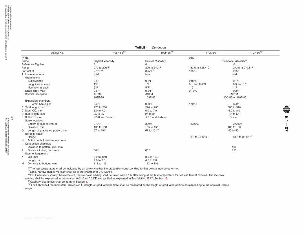
TABLE 1 Continued
ASTM No. 108F-86FF 109F-86FF 110C-86 110F-86FF
IP No. 93CName Saybolt Viscosity Saybolt Viscosity Kinematic ViscosityM
Reference Fig. No. 8 8 6Range 270 to 290°F 320 to 340°F 133.6 to 136.4°C 272.5 to 277.5°FFor test at 275°FG 325°FG 135°C 275°FA Immersion, mm total total total
Graduations:Subdivisions 0.5°F 0.5°F 0.05°C 0.1°FLong lines at each 1°F 1°F 0.1 and 0.5°C 0.5 and 1°FNumbers at each 5°F 5°F 1°C 1°F
Scale error, max 0.5°F 0.5°F 0.15°C 0.3°FSpecial inscription ASTM
108F-86ASTM109F-86
ASTM110C-86 or 110F-86
Expansion chamber:Permit heating to 340°F 390°F 170°C 350°F
B Total length, mm 270 to 280 270 to 280 300 to 310C Stem OD, mm 6.0 to 7.0 6.0 to 7.0 6.0 to 8.0D Bulb length, mm 25 to 35 25 to 35 45 to 55E Bulb OD, mm ≤5.0 and ≥stem ≤5.0 and ≥stem ≥stem
Scale location:Bottom of bulb to line at 270°F 320°F 133.6°C 272.5°F
F Distance, mm 135 to 150 135 to 150 160 to 180G Length of graduated portion, mm 67 to 101O 67 to 101O 40 to 90O
Ice-point scale:Range –0.3 to +0.6°C 31.5 to 33.0°FO
H Bottom of bulb to ice-point, mmContraction chamber:
I Distance to bottom, min, mm 100J Distance to top, max, mm 60H 60H 125
Stem enlargement:K OD, mm 8.0 to 10.0 8.0 to 10.0L Length, mm 4.0 to 7.0 4.0 to 7.0M Distance to bottom, mm 112 to 116 112 to 116
G The test temperature shall be indicated by an arrow whether the graduation corresponding to that point is numbered or not.H Long, narrow shape; mercury shall be in the chamber at 0°C (32°F).M For kinematic viscosity thermometers, the ice-point reading shall be taken within 1 h after being at the test temperature for not less than 3 minutes. The ice-point
reading shall be expressed to the nearest 0.01°C or 0.02°F and applied as explained in Test Method E 77, Section 13.O Capillary clearances shall conform to Section 8.FF For Fahrenheit thermometers, dimension G (length of graduated portion) shall be measured as the length of graduated portion corresponding to the nominal Celsius
range.
E1
–07
40C
opyright AS
TM
International P
rovided by IHS
under license with A
ST
M
Sold to:Inspectorate A
merica C
orp, 415918N
ot for Resale,03/03/2008 18:43:10 M
ST
No reproduction or netw
orking permitted w
ithout license from IH
S
--``,,`,,,,``,`,,```,``,,,`````,-`-`,,`,,`,`,,`---

TABLE 1 Continued
ASTM No. 111C-86 112C-86 113C-86 113F-86FF
IP No. 89CNameReference Fig. No.
Tar Acids Distillation7
Solidification Point of Benzene6
Softening Point (Bitumen) Wide Range4
Range 170 to 250°C 4 to 6°C −1 to + 175°C 30 to 350°FFor test at 5.4°CA Immersion, mm 100 total total
Graduations:SubdivisionsLong lines at eachNumbers at each
0.2°C1°C2°C
0.02°C0.1°C0.2°C
0.5°C1°C5°C
1°F5°F10°F
Scale error, max 0.4°C to 225°C0.6°C above 225°C
0.04°C 0.5°C 1°F
Special inscription ASTM111C-86100 MM IMM
ASTM112C-86
ASTM113C-86 or 113F-86
Expansion chamber:Permit heating to 275°C 50°C 225°C 440°F
B Total length, mm 390 to 400 210 to 220 400 to 410C Stem OD, mm 6.0 to 7.0 6.0 to 7.5 6.0 to 8.0D Bulb length, mm 10 to 15 25 to 35 10 to 15E Bulb OD, mm 6.0 to 7.0 6.0 to ≥stem 4.5 to 5.5
Scale location:Bottom of bulb to line at 170°C 4°C 0°C 32°F
FG
Distance, mmLength of graduated portion, mm
115 to 135200 to 245O
100 to 11545 to 75O
80 to 90250 to 290O
Ice-point scale:Range −0.2 to + 0.2°CO
H Bottom of bulb to ice-point, mm 60 to 70Contraction chamber:
I Distance to bottom, min, mm 80J Distance to top, max, mm 35 90II
KLM
Stem enlargement:OD, mmLength, mmDistance to bottom, mm
II Contraction chamber to be long narrow type.O Capillary clearances shall conform to Section 8.FF For Fahrenheit thermometers, dimension G (length of graduated portion) shall be measured as the length of graduated portion corresponding to the nominal Celsius range.
E1
–07
41C
opyright AS
TM
International P
rovided by IHS
under license with A
ST
M
Sold to:Inspectorate A
merica C
orp, 415918N
ot for Resale,03/03/2008 18:43:10 M
ST
No reproduction or netw
orking permitted w
ithout license from IH
S
--``,,`,,,,``,`,,```,``,,,`````,-`-`,,`,,`,`,,`---

TABLE 1 Continued
ASTM No. 114C-86 115C-86 116C-86 117C-86
IP No. 14CName Aviation Fuel Freezing PointB See Table 5 Bomb Calorimeter Bomb CalorimeterReference Fig. No. 4 9 and 14 9 and 14Range −80 to + 20°C 18.9 to 25.1°C 23.9 to 30.1°CFor test atA Immersion, mm total total total
Graduations:Subdivisions 0.5°C 0.01°C 0.01°CLong lines at each 1°C 0.05°C 0.05°CNumbers at each 5°C 0.1°C 0.1°C
Scale error, max 1°C 0.1°CJJ 0.1°CJJ
Special inscription ASTM ASTM ASTM114C-86 116C-86 117C-86
Expansion chamber:Permit heating to 45°C 60°C 60°C
B Total length, mm 295 to 305 604 to 614 604 to 614C Stem OD, mm 6.0 to 8.0 7.0 to 8.2 7.0 to 8.2D Bulb length, mm 8 to 16 KK KK
E Bulb OD, mm ≥stem 7.0 to 8.2BB 7.0 to 8.2BB
Scale location:Bottom of bulb to line at −80°C 19°C 24°C
F Distance, mm 50 to 70 220 to 240 220 to 240G Length of graduated portion, mm 170 to 210O 300 to 350O 300 to 350O
Ice-point scale:Range
H Bottom of bulb to ice-point, mmContraction chamber:
I Distance to bottom, min, mmJ Distance to top, max, mm 110 110
Stem enlargement:K OD, mmL Length, mmM Distance to bottom, mm
B Toluene or other suitable liquid colored red with a permanent dye shall be used as the actuating liquid.O Capillary clearances shall conform to Section 8.BB The bulb diameter shall not be more than 0.5 mm greater than the stem.JJ Over any interval of 1°C the change in correction shall not exceed 0.01°C. The correction at the lowest temperature of the nominal range shall not change by more than 0.02°C immediately after the
thermometer has been heated for 15 min at a temperature 30°C higher, and allowed to cool naturally in air.KK The capillary bore shall be large enough in relation to the bulb to ensure that (without tapping) jumping of the meniscus does not exceed one half of the smallest scale division, when the temperature is
rising at a uniform rate not exceeding 0.05°C/min.
E1
–07
42C
opyright AS
TM
International P
rovided by IHS
under license with A
ST
M
Sold to:Inspectorate A
merica C
orp, 415918N
ot for Resale,03/03/2008 18:43:10 M
ST
No reproduction or netw
orking permitted w
ithout license from IH
S
--``,,`,,,,``,`,,```,``,,,`````,-`-`,,`,,`,`,,`---

TABLE 1 Continued
ASTM No. 118C-86 118F-86FF 119C-86 119F-86FF 120C-86
IP No. 92CName Kinematic ViscosityM Coolant (Antifreeze)
Freezing PointKinematic
ViscosityM
Reference Fig. No. 6 10 6Range 28.6 to 31.4°C 83.5 to 88.5°F −38.3 to − 30°C −37 to − 22°F 38.6 to 41.4°CFor test at 30°C 86°F 40°CA Immersion, mm total 100LL total
Graduations:Subdivisions 0.05°C 0.1°F 0.1°C 0.2°F 0.05°CLong lines at each 0.1 and 0.5°C 0.5 and 1°F 0.5°C 1°F 0.1 and 0.5°CNumbers at each 1°C 1°F 1°C 2°F 1°C
Scale error, max 0.1°C 0.2°F 0.2°C 0.4°F 0.1°C
Special inscription ASTM ASTM ASTM118C-86 or 118F-86 119C-86 or 119F-86 120C-86
100 MM IMMExpansion chamber:
Permit heating to 105°C 220°F 50°C 122°F 105°CB Total length, mm 300 to 310 415 to 425 300 to 310C Stem OD, mm 6.0 to 8.0 6.0 to 7.0 6.0 to 8.0D Bulb length, mm 45 to 55 25 to 35 45 to 55E Bulb OD, mm ≥stem 5.0 to ≥stem ≥stem
Scale location:Bottom of bulb to line at 28.6°C 83.5°F −38.3°C −37°F 38.6°C
F Distance, mm 145 to 165 200 to 230 145 to 165G Length of graduated portion, mm 40 to 90O 60 to 110O 40 to 90O
Ice-point scale:Range −0.3 to + 0.3°CO 31.5 to 32.5°FO −0.5 to + 0.5°CO 31 to 33°FO −0.3 to + 0.3°CO
H Bottom of bulb to ice-point, mm 370 to 390Contraction chamber:
I Distance to bottom, min, mm 100 325 100J Distance to top, max, mm 125 350 125
Stem enlargement:K OD, mmL Length, mmM Distance to bottom, mm
M For kinematic viscosity thermometers, the ice-point reading shall be taken within 1 h after being at the test temperature for not less than 3 minutes. The ice-point reading shall be expressed to the nearest0.01°C or 0.02°F and applied as explained in Test Method E 77, Section 13.
O Capillary clearances shall conform to Section 8.FF For Fahrenheit thermometers, dimension G (length of graduated portion) shall be measured as the length of graduated portion corresponding to the nominal Celsius range.II The thermometer is to be calibrated for 100-mm immersion for the main scale, the ice point is to be calibrated for total immersion.
E1
–07
43C
opyright AS
TM
International P
rovided by IHS
under license with A
ST
M
Sold to:Inspectorate A
merica C
orp, 415918N
ot for Resale,03/03/2008 18:43:10 M
ST
No reproduction or netw
orking permitted w
ithout license from IH
S
--``,,`,,,,``,`,,```,``,,,`````,-`-`,,`,,`,`,,`---
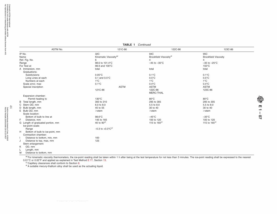
TABLE 1 Continued
ASTM No. 121C-86 122C-86 123C-86
IP No. 32C 94C 95CNameRef. Fig. No.
Kinematic ViscosityM
6Brookfield ViscosityR
4Brookfield Viscosity4
Range 98.6 to 101.4°C –45 to –35°C –35 to –25°CFor Test at 98.9 and 100°C 150°CA Immersion, mm total total total
Graduations:Subdivisions 0.05°C 0.1°C 0.1°CLong Lines at each 0.1 and 0.5°C 0.5°C 0.5°CNumbers at each 1°C 1°C 1°C
Scale error, max 0.1°C 0.4°C 0.4°CSpecial inscription ASTM
121C-86ASTM122C-86MERC-THAL
ASTM123C-86
Expansion chamber:Permit heating to 130°C 80°C 80°C
B Total length, mm 300 to 310 295 to 305 295 to 305C Stem OD, mm 6.0 to 8.0 5.5 to 8.0 5.5 to 8.0D Bulb length, mm 45 to 55 30 to 40 30 to 40E Bulb OD, mm ≥stem ≥stem ≥stem
Scale location:Bottom of bulb to line at 98.6°C –45°C –35°C
F Distance, mm 145 to 165 100 to 120 100 to 120G Length of graduated portion, mm 40 to 90O 115 to 165O 115 to 165O
Ice-point scale:Range –0.3 to +0.3°CO
H Bottom of bulb to ice-point, mmContraction chamber:
I Distance to bottom, min, mm 100J Distance to top, max, mm 125
Stem enlargement:KLM
OD, mmLength, mmDistance to bottom, mm
M For kinematic viscosity thermometers, the ice-point reading shall be taken within 1 h after being at the test temperature for not less than 3 minutes. The ice-point reading shall be expressed to the nearest0.01°C or 0.02°F and applied as explained in Test Method E 77, Section 13.
O Capillary clearances shall conform to Section 8.R A suitable mecury-thallium alloy shall be used as the actuating liquid.
E1
–07
44C
opyright AS
TM
International P
rovided by IHS
under license with A
ST
M
Sold to:Inspectorate A
merica C
orp, 415918N
ot for Resale,03/03/2008 18:43:10 M
ST
No reproduction or netw
orking permitted w
ithout license from IH
S
--``,,`,,,,``,`,,```,``,,,`````,-`-`,,`,,`,`,,`---
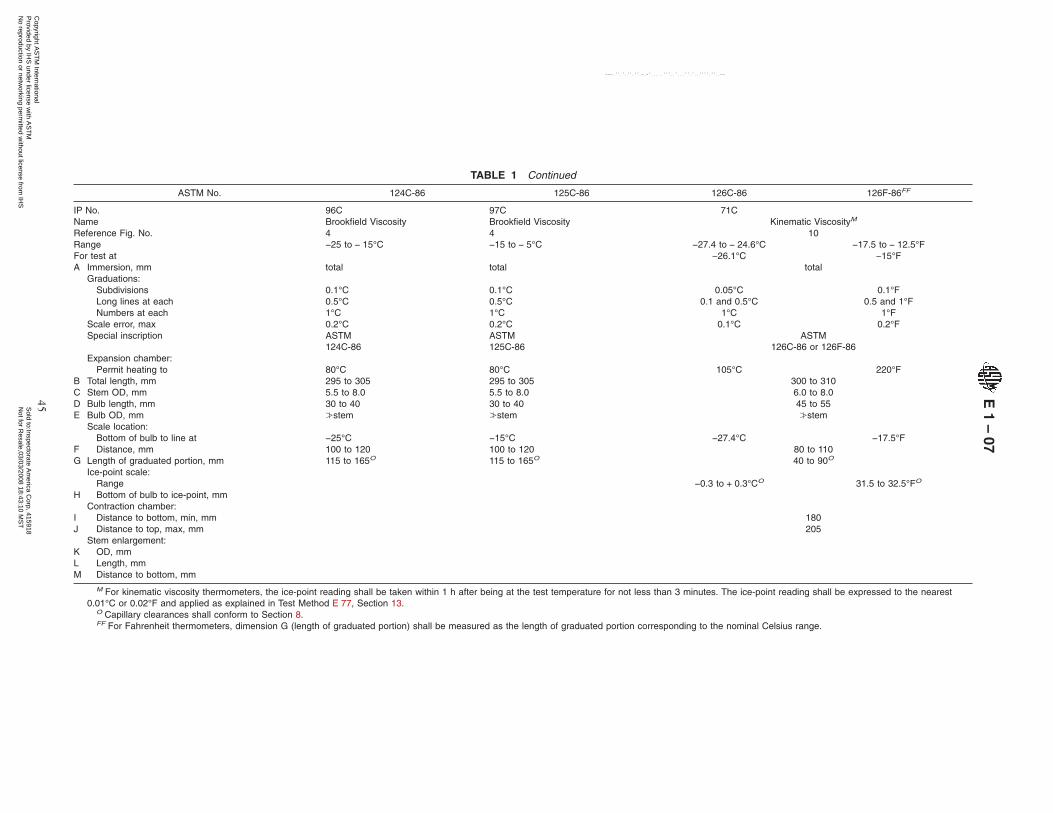
TABLE 1 Continued
ASTM No. 124C-86 125C-86 126C-86 126F-86FF
IP No. 96C 97C 71CName Brookfield Viscosity Brookfield Viscosity Kinematic ViscosityM
Reference Fig. No. 4 4 10Range −25 to − 15°C −15 to − 5°C −27.4 to − 24.6°C −17.5 to − 12.5°FFor test at −26.1°C −15°FA Immersion, mm total total total
Graduations:Subdivisions 0.1°C 0.1°C 0.05°C 0.1°FLong lines at each 0.5°C 0.5°C 0.1 and 0.5°C 0.5 and 1°FNumbers at each 1°C 1°C 1°C 1°F
Scale error, max 0.2°C 0.2°C 0.1°C 0.2°FSpecial inscription ASTM
124C-86ASTM125C-86
ASTM126C-86 or 126F-86
Expansion chamber:Permit heating to 80°C 80°C 105°C 220°F
B Total length, mm 295 to 305 295 to 305 300 to 310C Stem OD, mm 5.5 to 8.0 5.5 to 8.0 6.0 to 8.0D Bulb length, mm 30 to 40 30 to 40 45 to 55E Bulb OD, mm ≥stem ≥stem ≥stem
Scale location:Bottom of bulb to line at −25°C −15°C −27.4°C −17.5°F
F Distance, mm 100 to 120 100 to 120 80 to 110G Length of graduated portion, mm 115 to 165O 115 to 165O 40 to 90O
Ice-point scale:Range −0.3 to + 0.3°CO 31.5 to 32.5°FO
H Bottom of bulb to ice-point, mmContraction chamber:
I Distance to bottom, min, mm 180J Distance to top, max, mm 205
Stem enlargement:K OD, mmL Length, mmM Distance to bottom, mm
M For kinematic viscosity thermometers, the ice-point reading shall be taken within 1 h after being at the test temperature for not less than 3 minutes. The ice-point reading shall be expressed to the nearest0.01°C or 0.02°F and applied as explained in Test Method E 77, Section 13.
O Capillary clearances shall conform to Section 8.FF For Fahrenheit thermometers, dimension G (length of graduated portion) shall be measured as the length of graduated portion corresponding to the nominal Celsius range.
E1
–07
45C
opyright AS
TM
International P
rovided by IHS
under license with A
ST
M
Sold to:Inspectorate A
merica C
orp, 415918N
ot for Resale,03/03/2008 18:43:10 M
ST
No reproduction or netw
orking permitted w
ithout license from IH
S
--``,,`,,,,``,`,,```,``,,,`````,-`-`,,`,,`,`,,`---

TABLE 1 Continued
ASTM No. 127C-86 128C-86 128F-86FF 129C-86 129F-86FF
IP No. 99C 33C 36CName Kinematic ViscosityM Kinematic ViscosityM Kinematic ViscosityM
Ref. Fig. No. 10 4 6Range −21.4 to − 18.6°C −1.4 to + 1.4°C 29.5 to 34.5°F 91.6 to 94.4°C 197.5 to 202.5°FFor Test at −20°C 0°C 32°F 93.3°C 200°FA Immersion, mm total total total
Graduations:Subdivisions 0.05°C 0.05°C 0.1°F 0.05°C 0.1°FLong Lines at each 0.1 and 0.5°C 0.1 and 0.5°C 0.5 and 1°F 0.1 and 0.5°C 0.5 and 1°FNumbers at each 1°C 1°C 1°F 1°C 1°F
Scale error, max 0.1°C 0.1°C 0.2°F 0.1°C 0.2°FSpecial inscription ASTM
127C-86ASTM
128C-86 or 128F-86ASTM
129C-86 or 129F-86Expansion chamber:
Permit heating to 105°C 105°C 220°F 120°C 250°FB Total length, mm 300 to 310 300 to 310 300 to 310C Stem OD, mm 6.0 to 8.0 6.0 to 8.0 6.0 to 8.0D Bulb length, mm 45 to 55 45 to 55 45 to 55E Bulb OD, mm ≥stem ≥stem ≥stem
Scale location:Bottom of bulb to line at −21.4°C −1.4°C 29.5°F 91.6°C 197.5°F
F Distance, mm 80 to 110 145 to 165 145 to 165G Length of graduated portion, mm 40 to 90O 40 to 90O 40 to 90O
Ice-point scale:Range −0.3 to + 0.3°CO −0.3 to + 0.3°CO 31.5 to 32.5°FO
H Bottom of bulb to ice-point, mmContraction chamber:
I Distance to bottom, min, mm 180 100J Distance to top, max, mm 205 125
Stem enlargement:KLM
OD, mmLength, mmDistance to bottom, mm
M For kinematic viscosity thermometers, the ice-point reading shall be taken within 1 h after being at the test temperature for not less than 3 minutes. The ice-point reading shall be expressed to the nearest0.01°C or 0.02°F and applied as explained in Test Method E 77, Section 13.
O Capillary clearance shall conform to Section 8.FF For Fahrenheit thermometers, dimension G (length of graduated portion) shall be measured as the length of graduated portion corresponding to the nominal Celsius range.
E1
–07
46C
opyright AS
TM
International P
rovided by IHS
under license with A
ST
M
Sold to:Inspectorate A
merica C
orp, 415918N
ot for Resale,03/03/2008 18:43:10 M
ST
No reproduction or netw
orking permitted w
ithout license from IH
S
--``,,`,,,,``,`,,```,``,,,`````,-`-`,,`,,`,`,,`---
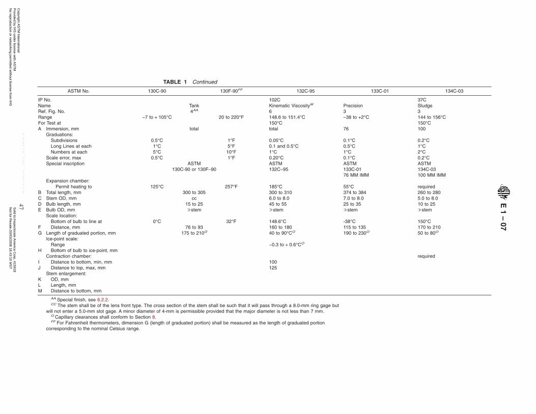
TABLE 1 Continued
ASTM No. 130C-90 130F-90FF 132C-95 133C-01 134C-03
IP No. 102C 37CNameRef. Fig. No.
Tank4AA
Kinematic ViscosityM
6Precision3
Sludge3
Range −7 to + 105°C 20 to 220°F 148.6 to 151.4°C –38 to +2°C 144 to 156°CFor Test at 150°C 150°CA Immersion, mm total total 76 100
Graduations:Subdivisions 0.5°C 1°F 0.05°C 0.1°C 0.2°CLong Lines at each 1°C 5°F 0.1 and 0.5°C 0.5°C 1°CNumbers at each 5°C 10°F 1°C 1°C 2°C
Scale error, max 0.5°C 1°F 0.20°C 0.1°C 0.2°CSpecial inscription ASTM
130C-90 or 130F–90ASTM132C–95
ASTM133C-0176 MM IMM
ASTM134C-03100 MM IMM
Expansion chamber:Permit heating to 125°C 257°F 185°C 55°C required
B Total length, mm 300 to 305 300 to 310 374 to 384 260 to 280C Stem OD, mm cc 6.0 to 8.0 7.0 to 8.0 5.0 to 8.0D Bulb length, mm 15 to 25 45 to 55 25 to 35 10 to 25E Bulb OD, mm ≥stem ≥stem ≥stem ≥stem
Scale location:Bottom of bulb to line at 0°C 32°F 148.6°C -38°C 150°C
F Distance, mm 76 to 93 160 to 180 115 to 135 170 to 210G Length of graduated portion, mm 175 to 210O 40 to 90°CO 190 to 230O 50 to 80O
Ice-point scale:Range −0.3 to + 0.6°CO
H Bottom of bulb to ice-point, mmContraction chamber: required
I Distance to bottom, min, mm 100J Distance to top, max, mm 125
Stem enlargement:KLM
OD, mmLength, mmDistance to bottom, mm
AA Special finish, see 6.2.2.CC The stem shall be of the lens front type. The cross section of the stem shall be such that it will pass through a 8.0-mm ring gage but
will not enter a 5.0-mm slot gage. A minor diameter of 4-mm is permissible provided that the major diameter is not less than 7 mm.O Capillary clearances shall conform to Section 8.FF For Fahrenheit thermometers, dimension G (length of graduated portion) shall be measured as the length of graduated portion
corresponding to the nominal Celsius range.
E1
–07
47C
opyright AS
TM
International P
rovided by IHS
under license with A
ST
M
Sold to:Inspectorate A
merica C
orp, 415918N
ot for Resale,03/03/2008 18:43:10 M
ST
No reproduction or netw
orking permitted w
ithout license from IH
S
--``,,`,,,,``,`,,```,``,,,`````,-`-`,,`,,`,`,,`---
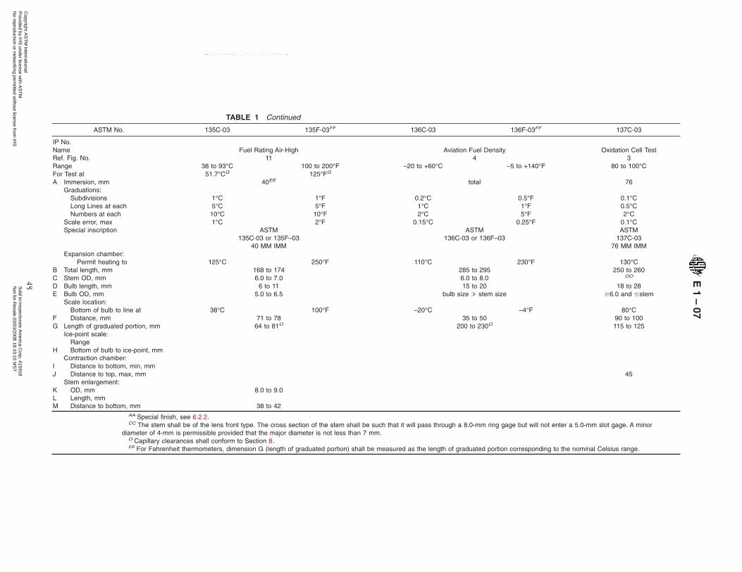
TABLE 1 Continued
ASTM No. 135C-03 135F-03FF 136C-03 136F-03FF 137C-03
IP No.NameRef. Fig. No.
Fuel Rating Air-High11
Aviation Fuel Density4
Oxidation Cell Test3
Range 38 to 93°C 100 to 200°F –20 to +60°C –5 to +140°F 80 to 100°CFor Test at 51.7°CG 125°FG
A Immersion, mm 40EE total 76Graduations:
Subdivisions 1°C 1°F 0.2°C 0.5°F 0.1°CLong Lines at each 5°C 5°F 1°C 1°F 0.5°CNumbers at each 10°C 10°F 2°C 5°F 2°C
Scale error, max 1°C 2°F 0.15°C 0.25°F 0.1°CSpecial inscription ASTM
135C-03 or 135F–0340 MM IMM
ASTM136C-03 or 136F–03
ASTM137C-03
76 MM IMMExpansion chamber:
Permit heating to 125°C 250°F 110°C 230°F 130°CB Total length, mm 168 to 174 285 to 295 250 to 260C Stem OD, mm 6.0 to 7.0 6.0 to 8.0 OO
D Bulb length, mm 6 to 11 15 to 20 18 to 28E Bulb OD, mm 5.0 to 6.5 bulb size ≥ stem size $6.0 and #stem
Scale location:Bottom of bulb to line at 38°C 100°F –20°C –4°F 80°C
F Distance, mm 71 to 78 35 to 50 90 to 100G Length of graduated portion, mm 64 to 81O 200 to 230O 115 to 125
Ice-point scale:Range
H Bottom of bulb to ice-point, mmContraction chamber:
I Distance to bottom, min, mmJ Distance to top, max, mm 45
Stem enlargement:KLM
OD, mmLength, mmDistance to bottom, mm
8.0 to 9.0
38 to 42AA Special finish, see 6.2.2.CC The stem shall be of the lens front type. The cross section of the stem shall be such that it will pass through a 8.0-mm ring gage but will not enter a 5.0-mm slot gage. A minor
diameter of 4-mm is permissible provided that the major diameter is not less than 7 mm.O Capillary clearances shall conform to Section 8.FF For Fahrenheit thermometers, dimension G (length of graduated portion) shall be measured as the length of graduated portion corresponding to the nominal Celsius range.
E1
–07
48C
opyright AS
TM
International P
rovided by IHS
under license with A
ST
M
Sold to:Inspectorate A
merica C
orp, 415918N
ot for Resale,03/03/2008 18:43:10 M
ST
No reproduction or netw
orking permitted w
ithout license from IH
S
--``,,`,,,,``,`,,```,``,,,`````,-`-`,,`,,`,`,,`---

TAB
LE
2A
lph
abetical
List
of
AS
TM
Th
ermo
meters
Co
veredb
yS
pecifi
cation
E1
NO
TE
1—T
hespecifications
appearin
numeric
sequencein
thisstandard.
Therm
ometer
Nam
eT
hermom
eterN
o.T
hermom
eterN
ame
Therm
ometer
No.
°C°F
°C°F
Aviation
fueldensity136C
136F...
...A
viationfuelfreezing
point114C
...3C
3FB
omb
calorimeter
56C56F
Petrolatum
melting
point61C
61F116C
...P
recision62C
62F117C
...63C
63FB
rookfieldV
iscosity122C
...64C
64F123C
...65C
65F124C
...66C
66F125C
...67C
67FB
utadieneboiling
pointrange
52C...
68C68F
Cleveland
openflash
11C11F
69C69F
Cloud
andpour
5C5F
70C70F
......
133C...
Cloud
andpour,
low6C
6FR
eidvapor
pressure18C
18FC
ongealingpoint
54C54F
Saybolt
viscosity17C
17FC
oolant(antifreeze)
freezingpoint
...75F
18C18F
...76F
19C19F
119C119F
20C20F
Density
wide
range12C
12F21C
21FE
nclosedscale
115C...
22C22F
Engler
viscosity23C
......
77F24C
......
78F25C
......
79FF
uelrating82C
82F...
80F83C
83F...
81F84C
84F...
108F85C
85F...
109F...
...S
ludge134C
...86C
86FS
ofteningpoint
(bitumen)
wide-range
113C113F
87C87F
Solidification
point89C
...135C
135F...
...G
ascalorim
eter,inlet
...50F
90C...
Gas
calorimeter,
outlet...
51F91C
...G
eneralpurpose—see
partialimm
ersion;precision
92C...
Gravity
12C12F
93C...
High
anilinepoint
35C35F
94C...
High
distillation8C
8F95C
...H
ighP
enskyM
artens10C
10F96C
...H
ighsoftening
point16C
16F100C
...K
inematic
viscosity28C
28F101C
...29C
29FS
olidificationpoint
ofbenzene
112C...
...30F
Solvents
distillation37C
...43C
43F38C
...44C
44F39C
...45C
45F40C
...46C
46F41C
...47C
47F42C
...48C
48F102C
...72C
72F103C
...73C
73F104C
...74C
74F105C
...110C
110F106C
...118C
118F107C
...120C
...S
tabilitytest
ofsoluble
nitrocellulose26C
...121C
...S
tormer
viscosity49C
...126C
126FTag
closedtester,
lowrange
57C57F
127C128C129C132C
...128F129F
Tagclosed
tester,high
rangeTank
9C58C59C
9F58F59F
Losson
heat13C
...60C
60FLow
anilinepoint
33C33F
97C97F
Lowcloud
andpour
6C6F
98C98F
Lowdistillation
7C7F
130C130F
LowP
enskyM
artens9C
9FTar
acidsdistillation
111C...
Lowsoftening
point15C
15FTiter
test36C
...M
ediumaniline
point34C
34FTurpentine
distillation27C
...O
ilinw
ax71C
71FV
egetableoilflash
88C88F
Oxidation
celltest137C
......
...
E1
–07
49C
opyright AS
TM
International P
rovided by IHS
under license with A
ST
M
Sold to:Inspectorate A
merica C
orp, 415918N
ot for Resale,03/03/2008 18:43:10 M
ST
No reproduction or netw
orking permitted w
ithout license from IH
S
--``,,`,,,,``,`,,```,``,,,`````,-`-`,,`,,`,`,,`---
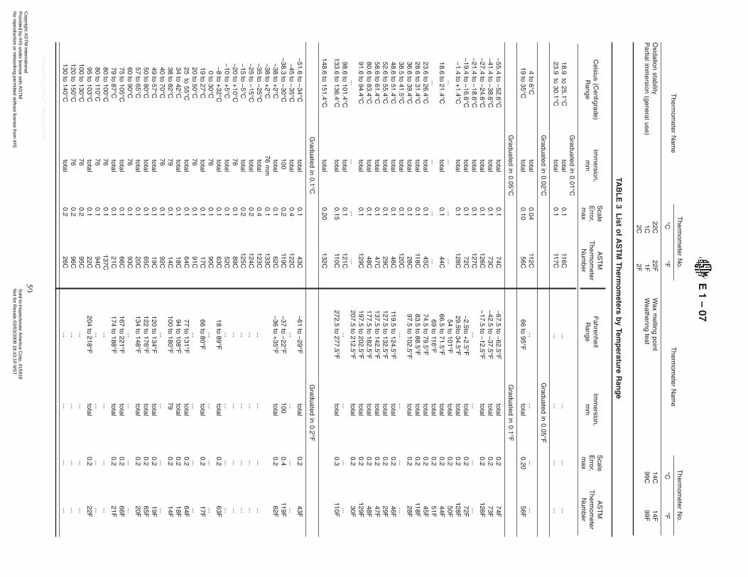
Therm
ometer
Nam
eT
hermom
eterN
o.T
hermom
eterN
ame
Therm
ometer
No.
°C°F
°C°F
Oxidation
stabilityP
artialimm
ersion(generaluse)
22C1C2C
22F1F2F
Wax
melting
pointW
eatheringtest
14C99C
14F99F
TAB
LE
3L
isto
fA
ST
MT
herm
om
etersb
yTem
peratu
reR
ang
e
Celsius
(Centigrade)
Range
Imm
ersion,m
m
Scale
Error,
max
AS
TM
Therm
ometer
Num
ber
FahrenheitR
angeIm
mersion,
mm
Scale
Error,
max
AS
TM
Therm
ometer
Num
ber
Graduated
in0.01°C
18.9to
25.1°Ctotal
0.1116C
......
......
23.9to
30.1°Ctotal
0.1117C
......
......
Graduated
in0.02°C
Graduated
in0.05°F
4to
6°Ctotal
0.04112C
......
......
19to
35°Ctotal
0.1056C
66to
95°Ftotal
0.2056F
Graduated
in0.05°C
Graduated
in0.1°F
−55.4
to−
52.6°Ctotal
0.174C
−67.5
to−
62.5°Ftotal
0.274F
−41.4
to−
38.6°Ctotal
0.173C
−42.5
to−
37.5°Ftotal
0.273F
−27.4
to−
24.6°Ctotal
0.1126C
−17.5
to−
12.5°Ftotal
0.2126F
−21.4
to−
18.6°Ctotal
0.1127C
......
......
−19.4
to−
16.6°Ctotal
0.172C
−2.5to
+2.5°F
total0.2
72F−
1.4to
+1.4°C
total0.1
128C29.5to
34.5°Ftotal
0.2128F
......
......
54to
101°Ftotal
0.250F
18.6to
21.4°Ctotal
0.144C
66.5to
71.5°Ftotal
0.244F
......
......
69to
116°Ftotal
0.251F
23.6to
26.4°Ctotal
0.145C
74.5to
79.5°Ftotal
0.245F
28.6to
31.4°Ctotal
0.1118C
83.5to
88.5°Ftotal
0.2118F
36.6to
39.4°Ctotal
0.128C
97.5to
102.5°Ftotal
0.228F
38.5to
41.5°Ctotal
0.1120C
......
......
48.6to
51.4°Ctotal
0.146C
119.5to
124.5°Ftotal
0.246F
52.6to
55.4°Ctotal
0.129C
127.5to
132.5°Ftotal
0.229F
58.6to
61.4°Ctotal
0.147C
137.5to
142.5°Ftotal
0.247F
80.6to
83.4°Ctotal
0.148C
177.5to
182.5°Ftotal
0.248F
91.6to
94.4°Ctotal
0.1129C
197.5to
202.5°Ftotal
0.2129F
......
......
207.5to
212.5°Ftotal
0.230F
98.6to
101.4°Ctotal
0.1121C
......
......
133.6to
136.4°Ctotal
0.15110C
272.5to
277.5°Ftotal
0.3110F
148.6to
151.4°Ctotal
0.20132C
Graduated
in0.1°C
Graduated
in0.2°F
−51.6
to−
34°Ctotal
0.143C
−61
to−
29°Ftotal
0.243F
−45
to−
35°Ctotal
0.4122C
......
......
−38.3
to−
30°C100
0.2119C
−37
to−
22°F100
0.4119F
−38
to+
2°Ctotal
0.162C
−36
to+
35°Ftotal
0.262F
–38to
+2°C
76m
m0.1
133C−
35to
−25°C
total0.4
123C...
......
...−
25to
−15°C
total0.2
124C...
......
...−
15to
−5°C
total0.2
125C...
......
...−
20to
+10°C
760.1
89C...
......
...−
10to
+5°C
total0.1
52C...
......
...−
8to
+32°C
total0.1
63C18
to89°F
total0.2
63F0
to30°C
760.1
90C...
......
...19
to27°C
total0.1
17C66
to80°F
total0.2
17F20
to50°C
760.1
91C...
......
...25
to55°C
total0.1
64C77
to131°F
total0.2
64F34
to42°C
total0.1
18C94
to108°F
total0.2
18F38
to82°C
790.1
14C100
to180°F
790.2
14F40
to70°C
760.1
92C...
......
...49
to57°C
total0.1
19C120
to134°F
total0.2
19F50
to80°C
total0.1
65C122
to176°F
total0.2
65F57
to65°C
total0.1
20C134
to148°F
total0.2
20F60
to90°C
760.1
93C...
......
...75
to105°C
total0.1
66C167
to221°F
total0.2
66F79
to87°C
total0.1
21C174
to188°F
total0.2
21F80
to100°C
760.1
137C...
......
...80
to110°C
760.1
94C...
......
...95
to103°C
total0.1
22C204
to218°F
total0.2
22F100
to130°C
760.2
95C...
......
...120
to150°C
760.2
96C...
......
...130
to140°C
total0.2
26C...
......
...
E1
–07
50C
opyright AS
TM
International P
rovided by IHS
under license with A
ST
M
Sold to:Inspectorate A
merica C
orp, 415918N
ot for Resale,03/03/2008 18:43:10 M
ST
No reproduction or netw
orking permitted w
ithout license from IH
S
--``,,`,,,,``,`,,```,``,,,`````,-`-`,,`,,`,`,,`---

TAB
LE
3C
ontinued
Celsius
(Centigrade)
Range
Imm
ersion,m
m
Scale
Error,
max
AS
TM
Therm
ometer
Num
ber
FahrenheitR
angeIm
mersion,
mm
Scale
Error,
max
AS
TM
Therm
ometer
Num
ber
Graduated
in0.2°C
Graduated
in0.5°F
......
......
−65
to+
5°F100
176F
−50
to+
5°C35
0.299C
−55
to+
40°F35
0.499F
−38
to+
42°C50
0.233C
−36.5
to+
107.5°F50
0.533F
......
......
−35
to+
35°F100
0.575F
−20
to+
60°Ctotal
0.15136C
−5
to+
140°Ftotal
0.25136F
−20
to+
102°Ctotal
0.1512C
−5
to+
215°Ftotal
0.2512F
−2
to+
52°C100
0.237C
......
......
−2
to+
68°C45
0.236C
......
......
−2
to+
80°Ctotal
0.215C
30to
180°Ftotal
0.415F
18to
28°C90
0.123C
......
......
20to
70°C65
0.249C
......
......
20to
100.6°Ctotal
0.254C
68to
213°Ftotal
0.554F
24to
78°C100
0.238C
......
......
25to
105°C50
0.234C
77to
221°F50
0.534F
32to
127°C79
0.261C
90to
260°F79
0.561F
39to
54°C90
0.124C
......
......
48to
102°C100
0.239C
......
......
72to
126°C100
0.240C
......
......
90to
170°C50
0.435C
194to
338°F50
135F
95to
105°C90
0.125C
......
......
98to
152°C100
0.341C
......
......
95to
155°Ctotal
0.267C
203to
311°Ftotal
0.567F
......
......
245to
265°Ftotal
0.577F
123to
177°C100
0.3102C
......
......
......
......
270to
290°Ftotal
0.5108F
144to
156°C100
0.2134C
295to
315°Ftotal
0.578F
145to
205°Ctotal
0.268C
293to
401°Ftotal
0.568F
145to
205°C76
0.4100C
......
......
148to
202°C100
0.4103C
......
......
......
......
320to
340°Ftotal
0.5109F
170to
250°C100
A111C
......
......
173to
227°C100
0.4104C
......
......
......
......
345to
365°Ftotal
0.579F
198to
252°C100
0.6105C
......
......
......
......
395to
415°Ftotal
0.580F
......
......
445to
465°Ftotal
0.581F
223to
277°C100
0.8106C
......
......
248to
302°C100
1107C
......
......
Graduated
in0.5°C
Graduated
in1°F
−80
to+
20°Ctotal
1114C
......
......
−37
to+
21°C76
0.271C
−35
to+
70°F76
0.571F
−34
to+
49°Ctotal
0.558C
−30
to+
120°Ftotal
0.558F
−20
to+
50°C57
0.557C
−4
to+
122°F57
157F
−18
to+
49°Ctotal
0.597C
0to
120°Ftotal
0.597F
−18
to+
82°Ctotal
0.559C
0to
180°Ftotal
0.559F
−7
to+
105°Ctotal
0.5130C
20to
220°Ftotal
1130F
−5
to+
110°C57
0.59C
20to
230°F57
19F
−1
to+
175°Ctotal
0.5113C
30to
350°Ftotal
1113F
......
......
60to
160°F40
283F
16to
82°Ctotal
0.598C
60to
180°Ftotal
0.598F
......
......
75to
175°F249
284F
30to
200°Ctotal
0.316C
85to
392°Ftotal
0.516F
95to
255°C100
142C
100to
200°F40
2135F
147to
182°C76
0.527C
......
......
155to
170°Ctotal
0.513C
......
......
......
......
300to
400°F40
287F
195to
305°Ctotal
0.569C
383to
581°Ftotal
169F
195to
305°C76
1101C
......
......
295to
405°Ctotal
0.570C
563to
761°Ftotal
170F
Graduated
in1°C
Graduated
in2°F
−80
to+
20°C76
B6C
−112
to+
70°F76
C6F
−38
to+
50°C108
0.55C
−36
to+
120°F108
15F
−15
to+
105°C30
182C
0to
220°F30
282F
−20
to+
150°C76
0.51C
0to
302°F76
11F
−5
to+
300°C76
12C
20to
580°F76
22F
−5
to+
400°C76
D3C
20to
760°F76
E3F
−2
to+
300°Ctotal
F7C
30to
580°Ftotal
G7F
−2
to+
400°Ctotal
H8C
30to
760°Ftotal
I8F
10to
200°C57
188C
50to
392°F57
288F
E1
–07
51C
opyright AS
TM
International P
rovided by IHS
under license with A
ST
M
Sold to:Inspectorate A
merica C
orp, 415918N
ot for Resale,03/03/2008 18:43:10 M
ST
No reproduction or netw
orking permitted w
ithout license from IH
S
--``,,`,,,,``,`,,```,``,,,`````,-`-`,,`,,`,`,,`---

TAB
LE
3C
ontinued
Celsius
(Centigrade)
Range
Imm
ersion,m
m
Scale
Error,
max
AS
TM
Therm
ometer
Num
ber
FahrenheitR
angeIm
mersion,
mm
Scale
Error,
max
AS
TM
Therm
ometer
Num
ber
15to
70°C40
183C
......
......
25to
80°C249
184C
......
......
38to
93°C40
1135C
......
......
40to
150°C181
185C
100to
300°F181
285F
77to
260°Ctotal
160C
170to
500°Ftotal
160F
95to
175°C35
186C
200to
350°F35
286F
150to
205°C40
187C
......
......
Graduated
in2°C
Graduated
in5°F
−6
to+
400°C25
J11C
20to
760°F25
K11F
90to
370°C57
L10C
200to
700°F57
M10F
A0.4°C
to225°C
;0.6°C
above225°C
.B
1°Cto
−33°C
;2°C
below−
33°C.
C2°F
to−
28°F;
4°Fbelow
−28°F.
D1°C
to301°C
;1.5°C
above301°C
.E
2°Fto
574°F;
3°Fabove
574°F.F
0.5°Cto
150°C;
1°Cabove
150°C.
G1°F
to300°F
;2°F
above300°F.
H1°C
to300°C
;1.5°C
above300°C
.I2°F
to570°F
;3°F
above570°F.
J2°C
to260°C
;4°C
above260°C
.K
5°Fto
500°F;
7°Fabove
500°F.L
1°Cto
260°C;
2°Cabove
260°C.
M2.5°F
to500°F
;3.5°F
above500°F.
TAB
LE
4V
erificatio
nan
dC
alibratio
nTem
peratu
resA
Temperature
Av
Temp.
ofE
mergent
Mercury
Colum
n
Temperature
Av
Temp.
ofE
mergent
Mercury
Colum
n
Temperature
Av
Temp.
ofE
mergent
Mercury
Colum
n
Temperature
Av
Temp.
ofE
mergent
Mercury
Colum
n
Therm
ometer
1C−
20to
+150°C
Therm
ometer
1F0
to302°F
Therm
ometer
2C−
5to
+300°C
Therm
ometer
2F−
20to
+580°F
−20°C
15°C0°F
60°F0°C
22°C32°F
72°F0°C
22°C32°F
72°F75°C
34°C150°F
90°F50°C
30°C122°F
86°F150°C
35°C300°F
95°F100°C
33°C212°F
91°F225°C
40°C450°F
105°F150°C
36°C302°F
97°F300°C
45°C580°F
114°F
Therm
ometer
3C−
5to
+400°C
Therm
ometer
3F20
to760°F
Therm
ometer
5C−
38to
+50°C
Therm
ometer
5F−
36to
+120°F
0°C21°C
32°F70°F
−35°C
21°C−
30°F70°F
100°C33°C
200°F90°F
0°C21°C
32°F70°F
200°C39°C
370°F101°F
50°C21°C
120°F70°F
300°C44°C
540°F110°F
370°C54°C
700°F129°F
Therm
ometer
6C−
80to
+20°C
Therm
ometer
6F−
112to
+70°F
Therm
ometer
7C−
2to
+300°C
Therm
ometer
7F30
to580°F
−70°C
21°C−
94°F70°F
0°C32°F
−35°C
21°C−
30°F70°F
50°C100°F
0°CB
21°C32°F
B70°F
100°C200°F
20°C21°C
70°F70°F
150°C300°F
200°C400°F
250°C500°F
300°C570°F
Therm
ometer
8C−
2to
+400°C
Therm
ometer
8F30
to760°F
Therm
ometer
9C−
5to
+110°C
Therm
ometer
9F20
to230°F
0°C32°F
0°C19°C
32°F66°F
100°C200°F
35°C28°C
100°F86°F
200°C370°F
70°C40°C
160°F106°F
300°C540°F
105°C50°C
220°F123°F
370°C700°F
Therm
ometer
10C90
to370°C
Therm
ometer
10F200
to700°F
Therm
ometer
11C−
6to
+400°C
Therm
ometer
11F20
to760°F
100°C61°C
212°F141°F
0°C18°C
32°F64°F
200°C71°C
390°F159°F
100°C44°C
200°F110°F
300°C87°C
570°F189°F
200°C64°C
370°F144°F
E1
–07
52C
opyright AS
TM
International P
rovided by IHS
under license with A
ST
M
Sold to:Inspectorate A
merica C
orp, 415918N
ot for Resale,03/03/2008 18:43:10 M
ST
No reproduction or netw
orking permitted w
ithout license from IH
S
--``,,`,,,,``,`,,```,``,,,`````,-`-`,,`,,`,`,,`---
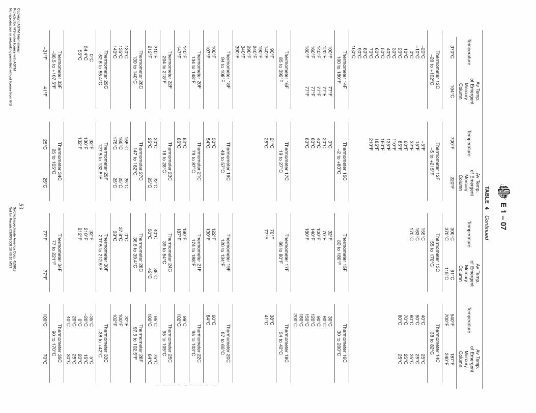
TAB
LE
4C
ontinued
Temperature
Av
Temp.
ofE
mergent
Mercury
Colum
n
Temperature
Av
Temp.
ofE
mergent
Mercury
Colum
n
Temperature
Av
Temp.
ofE
mergent
Mercury
Colum
n
Temperature
Av
Temp.
ofE
mergent
Mercury
Colum
n
370°C104°C
700°F220°F
300°C91°C
540°F187°F
370°C115°C
700°F240°F
Therm
ometer
12C−
20to
+102°C
Therm
ometer
12F−
5to
+215°F
Therm
ometer
13C155
to170°C
Therm
ometer
14C38
to82°C
−20°C
−5°F
155°C40°C
25°C−
10°C15°F
163°C50°C
25°C0°C
32°F170°C
60°C25°C
10°C60°F
70°C25°C
20°C85°F
80°C25°C
30°C110°F
40°C135°F
50°C160°F
60°C185°F
70°C210°F
80°C90°C
100°C
Therm
ometer
14F100
to180°F
Therm
ometer
15C−
2to
+80°C
Therm
ometer
15F30
to180°F
Therm
ometer
16C30
to200°C
100°F77°F
0°C32°F
30°C120°F
77°F20°C
70°F60°C
140°F77°F
40°C100°F
90°C160°F
77°F60°C
140°F120°C
180°F77°F
80°C180°F
150°C180°C200°C
Therm
ometer
16F85
to392°F
Therm
ometer
17C19
to27°C
Therm
ometer
17F66
to80°F
Therm
ometer
18C34
to42°C
90°F21°C
70°F38°C
140°F25°C
77°F41°C
190°F240°F290°F340°F390°F
Therm
ometer
18F94
to108°F
Therm
ometer
19C49
to57°C
Therm
ometer
19F120
to134°F
Therm
ometer
20C57
to65°C
100°F107°F
50°C54°C
122°F130°F
60°C64°C
Therm
ometer
20F134
to148°F
Therm
ometer
21C79
to87°C
Therm
ometer
21F174
to188°F
Therm
ometer
22C95
to103°C
140°F147°F
82°C86°C
180°F187°F
99°C102°C
Therm
ometer
22F204
to218°F
Therm
ometer
23C18
to28°C
Therm
ometer
24C39
to54°C
Therm
ometer
25C95
to105°C
210°F212°F
20°C25°C
22°C25°C
40°C50°C
35°C42°C
95°C100°C
75°C64°C
Therm
ometer
26C130
to140°C
Therm
ometer
27C147
to182°C
Therm
ometer
28C36.6
to39.4°C
Therm
ometer
28F97.5
to102.5°F
130°C135°C140°C
155°C165°C175°C
25°C25°C25°C
0°C37.8°C
39°C
32°F100°F102°F
Therm
ometer
29C52.6
to55.4°C
Therm
ometer
29F127.5
to132.5°F
Therm
ometer
30F207.5
to212.5°F
Therm
ometer
33C−
38to
+42°C
0°C54.4°C
55°C
32°F130°F132°F
32°F210°F212°F
−35°C
−20°C0°C
20°C40°C
5°C15°C20°C25°C30°C
Therm
ometer
33F−
36.5to
+107.5°F
Therm
ometer
34C25
to105°C
Therm
ometer
34F77
to221°F
Therm
ometer
35C90
to170°C
−31°F
41°F25°C
25°C77°F
77°F100°C
70°C
E1
–07
53C
opyright AS
TM
International P
rovided by IHS
under license with A
ST
M
Sold to:Inspectorate A
merica C
orp, 415918N
ot for Resale,03/03/2008 18:43:10 M
ST
No reproduction or netw
orking permitted w
ithout license from IH
S
--``,,`,,,,``,`,,```,``,,,`````,-`-`,,`,,`,`,,`---
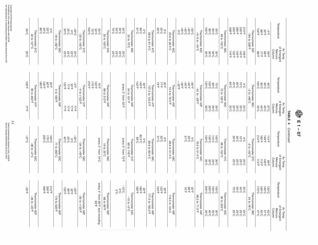
TAB
LE
4C
ontinued
Temperature
Av
Temp.
ofE
mergent
Mercury
Colum
n
Temperature
Av
Temp.
ofE
mergent
Mercury
Colum
n
Temperature
Av
Temp.
ofE
mergent
Mercury
Colum
n
Temperature
Av
Temp.
ofE
mergent
Mercury
Colum
n
−4°F
59°F45°C
37°C113°F
99°F120°C
63°C32°F
68°F65°C
43°C149°F
109°F140°C
57°C68°F
77°F85°C
45°C185°F
113°F160°C
50°C104°F
86°F100°C
45°C212°F
113°F170°C
47°C
Therm
ometer
35F194
to338°F
Therm
ometer
36C−
2to
+68°C
Therm
ometer
37C−
2to
+52°C
Therm
ometer
38C24
to78°C
212°F158°F
0°C25°C
0°C25°C
25°C25°C
250°F145°F
15°C25°C
15°C25°C
40°C25°C
285°F134°F
30°C25°C
30°C25°C
55°C25°C
320°F122°F
45°C25°C
50°C25°C
75°C25°C
338°F116°F
65°C25°C
Therm
ometer
39C48
to102°C
Therm
ometer
40C72
to126°C
Therm
ometer
41C98
to152°C
Therm
ometer
42C95
to255°C
50°C30°C
75°C30°C
100°C30°C
100°C30°C
65°C30°C
90°C30°C
115°C33°C
150°C35°C
80°C30°C
105°C30°C
130°C35°C
200°C40°C
100°C30°C
125°C30°C
150°C35°C
250°C45°C
Therm
ometer
43C−
51.6to
−34°C
Therm
ometer
43F−
61to
−29°F
Therm
ometer
44C18.6
to21.4°C
Therm
ometer
44F66.5
to71.5°F
−50°C
−45°C
−40°C
−35°C0°C
−60°F
−50°F
−40°F
−30°F
+32°F
0°C20°C21°C
32°F68°F70°F
Therm
ometer
45C23.6
to26.4°C
Therm
ometer
45F74.5
to79.5°F
Therm
ometer
46C48.6
to51.4°C
Therm
ometer
46F119.5
to124.5
0°C25°C26°C
32°F77°F79°F
0°C50°C51°C
32°F122°F124°F
Therm
ometer
47C58.6
to61.4°C
Therm
ometer
47F137.5
to142.5°F
Therm
ometer
48C80.6
to83.4°C
Therm
ometer
48F177.5
to182.5°F
0°C60°C61°C
32°F140°F142°F
0°C82.2°C
83°C
32°F180°F182°F
Therm
ometer
49C20
to70°C
Therm
ometer
50F54
to101°F
Therm
ometer
51F69
to116°F
Therm
ometer
52C−
10to
+5°C
20°C35°C50°C70°C
25°C25°C25°C25°C
every5°
from55°F
every5°
from70°F
−10°C
0°C5°C
Therm
ometer
54C20
to100°C
Therm
ometer
54F68
to213°F
Therm
ometer
56C19
to35°C
Therm
ometer
56F66
to95°F
20°C50°C75°C
100°C
70°F120°F170°F210°F
every2°
from19°C
every4°
from66°F
andincluding
95°F
Therm
ometer
57C−
20to
+50°C
Therm
ometer
57F−
4to
+122°F
Therm
ometer
58C−
34to
+49°C
Therm
ometer
58F−
30to
+120°F
−20°C
25°C−
3°F77°F
−30°C
−20°F
0°C25°C
32°F77°F
0°C32°F
25°C25°C
77°F77°F
25°C80°F
50°C25°C
122°F77°F
45°C120°F
Therm
ometer
59C−
18to
+82°C
Therm
ometer
59F0
to180°F
Therm
ometer
60C77
to260°C
Therm
ometer
60F170
to500°F
0°C25°C55°C80°C
32°F80°F130°F180°F
100°C175°C255°C
212°F350°F490°F
Therm
ometer
61C32
to127°C
Therm
ometer
61F90
to260°F
Therm
ometer
62C−
38to
+2°C
Therm
ometer
62F−
36to
+35°F
40°C25°C
100°F77°F
−37°C
−35°F
E1
–07
54C
opyright AS
TM
International P
rovided by IHS
under license with A
ST
M
Sold to:Inspectorate A
merica C
orp, 415918N
ot for Resale,03/03/2008 18:43:10 M
ST
No reproduction or netw
orking permitted w
ithout license from IH
S
--``,,`,,,,``,`,,```,``,,,`````,-`-`,,`,,`,`,,`---

TAB
LE
4C
ontinued
Temperature
Av
Temp.
ofE
mergent
Mercury
Colum
n
Temperature
Av
Temp.
ofE
mergent
Mercury
Colum
n
Temperature
Av
Temp.
ofE
mergent
Mercury
Colum
n
Temperature
Av
Temp.
ofE
mergent
Mercury
Colum
n
60°C25°C
150°F77°F
−30°C
−15°F
80°C25°C
200°F77°F
−20°C
0°F100°C
25°C250°F
77°F−
10°C15°F
120°C25°C
0°C32°F
Therm
ometer
63C−
8to
+32°C
Therm
ometer
63F18
to89°F
Therm
ometer
64C25
to55°C
Therm
ometer
64F77
to131°F
−7°C
20°F0°C
32°F0°C
32°F25°C
80°F10°C
50°F35°C
95°F20°C
70°F45°C
115°F30°C
88°F55°C
130°F
Therm
ometer
65C50
to80°C
Therm
ometer
65F122
to176°F
Therm
ometer
66C75
to105°C
Therm
ometer
66F167
to221°F
0°C32°F
0°C32°F
50°C125°F
75°C168°F
60°C145°F
85°C185°F
70°C160°F
95°C200°F
80°C175°F
105°C220°F
Therm
ometer
67C95
to155°C
Therm
ometer
67F203
to311°F
Therm
ometer
68C145
to205°C
Therm
ometer
68F293
to401°F
0°C32°F
0°C32°F
100°C205°F
150°C300°F
110°C240°F
170°C340°F
130°C275°F
190°C370°F
150°C310°F
205°C400°F
Therm
ometer
69C195
to305°C
Therm
ometer
69F383
to581°F
Therm
ometer
70C295
to405°C
Therm
ometer
70F563
to761°F
0°C32°F
0°C32°F
200°C400°F
300°C570°F
235°C460°F
335°C640°F
270°C520°F
370°C700°F
305°C580°F
400°C760°F
Therm
ometer
71C−
37to
+21°C
Therm
ometer
71F−
35to
+70°F
Therm
ometer
72C−
19.4to
−16.6°C
Therm
ometer
72F−
2.5to
+2.5°F
−35°C
21°C−
30°F70°F
−19°C
−2°F
−18°C
21°C0°F
70°F−
17.8°C0°F
0°C21°C
32°F70°F
0°C32°F
20°C21°C
70°F70°F
Therm
ometer
73C−
41.4to
−38.6°C
Therm
ometer
73F−
42.5to
−37.5°F
Therm
ometer
74C−
55.4to
−52.6°C
Therm
ometer
74F−
67.5to
−62.5°F
−41°C
−40°C0°C
−42°F
−40°F32°F
−55°C
−53.9°C
0°C
−67°F
−65°F32°F
Therm
ometer
75F−
35to
+35°F
Therm
ometer
76F−
65to
+5°F
Therm
ometer
77F245
to265°F
Therm
ometer
78F295
to315°F
−35°F0°F
32°F
55°F65°F75°F
−65°F
−30°F
+5°F
25°F55°F75°F
250°F260°F
300°F310°F
Therm
ometer
79F345
to365°F
Therm
ometer
80F395
to415°F
Therm
ometer
81F445
to465°F
Therm
ometer
82C−
15to
+105°C
350°F360°F
400°F410°F
450°F460°F
0°C50°C
100°C
71°C71°C71°C
Therm
ometer
82F0
to220°F
Therm
ometer
83C15
to70°C
Therm
ometer
83F60
to160°F
Therm
ometer
84C25
to80°C
32°F100°F200°F
160°F160°F160°F
25°C70°C
35°C35°C
85°F135°F
95°F95°F
30°C80°C
27°C27°C
Therm
ometer
84F75
to175°F
Therm
ometer
85C40
to150°C
Therm
ometer
85F100
to300°F
Therm
ometer
86C95
to175°C
E1
–07
55C
opyright AS
TM
International P
rovided by IHS
under license with A
ST
M
Sold to:Inspectorate A
merica C
orp, 415918N
ot for Resale,03/03/2008 18:43:10 M
ST
No reproduction or netw
orking permitted w
ithout license from IH
S
--``,,`,,,,``,`,,```,``,,,`````,-`-`,,`,,`,`,,`---
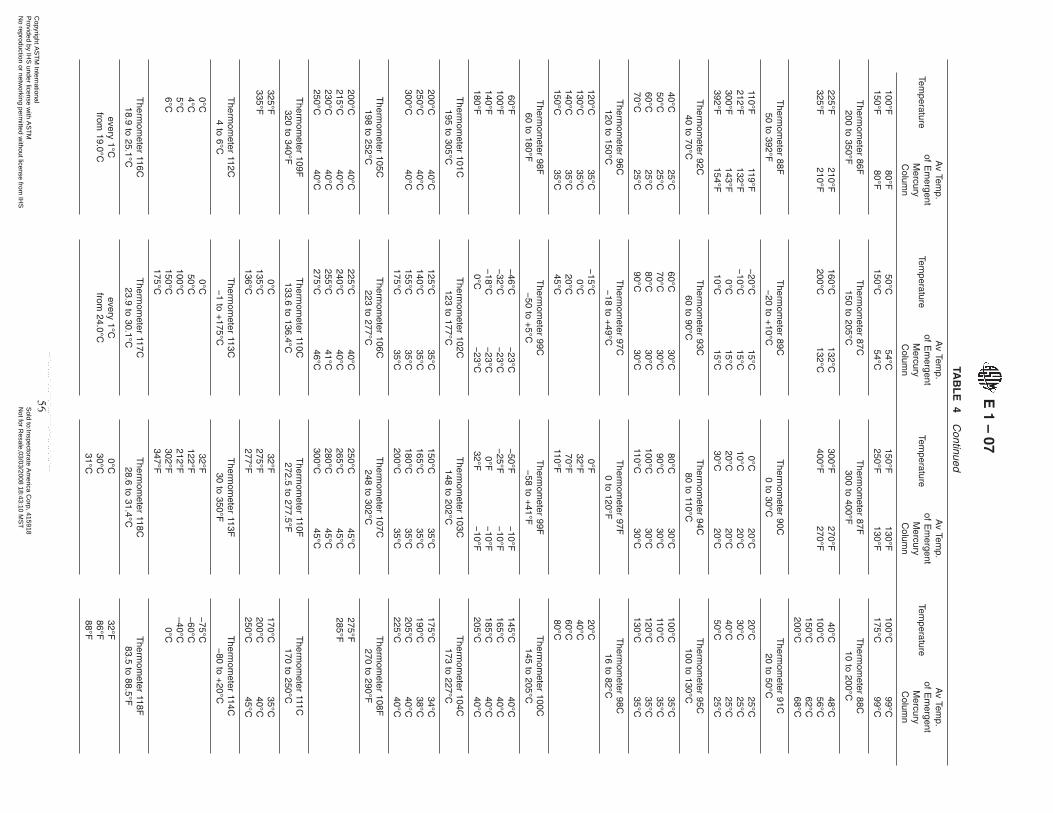
TAB
LE
4C
ontinued
Temperature
Av
Temp.
ofE
mergent
Mercury
Colum
n
Temperature
Av
Temp.
ofE
mergent
Mercury
Colum
n
Temperature
Av
Temp.
ofE
mergent
Mercury
Colum
n
Temperature
Av
Temp.
ofE
mergent
Mercury
Colum
n
100°F150°F
80°F80°F
50°C150°C
54°C54°C
150°F250°F
130°F130°F
100°C175°C
99°C99°C
Therm
ometer
86F200
to350°F
Therm
ometer
87C150
to205°C
Therm
ometer
87F300
to400°F
Therm
ometer
88C10
to200°C
225°F325°F
210°F210°F
160°C200°C
132°C132°C
300°F400°F
270°F270°F
40°C100°C150°C200°C
48°C56°C62°C68°C
Therm
ometer
88F50
to392°F
Therm
ometer
89C−
20to
+10°C
Therm
ometer
90C0
to30°C
Therm
ometer
91C20
to50°C
110°F119°F
−20°C
15°C0°C
20°C20°C
25°C212°F
132°F−
10°C15°C
10°C20°C
30°C25°C
300°F143°F
0°C15°C
20°C20°C
40°C25°C
392°F154°F
10°C15°C
30°C20°C
50°C25°C
Therm
ometer
92C40
to70°C
Therm
ometer
93C60
to90°C
Therm
ometer
94C80
to110°C
Therm
ometer
95C100
to130°C
40°C25°C
60°C30°C
80°C30°C
100°C35°C
50°C25°C
70°C30°C
90°C30°C
110°C35°C
60°C25°C
80°C30°C
100°C30°C
120°C35°C
70°C25°C
90°C30°C
110°C30°C
130°C35°C
Therm
ometer
96C120
to150°C
Therm
ometer
97C−
18to
+49°C
Therm
ometer
97F0
to120°F
Therm
ometer
98C16
to82°C
120°C130°C140°C150°C
35°C35°C35°C35°C
−15°C0°C
20°C45°C
0°F32°F70°F
110°F
20°C40°C60°C80°C
Therm
ometer
98F60
to180°F
Therm
ometer
99C−
50to
+5°C
Therm
ometer
99F−
58to
+41°F
Therm
ometer
100C145
to205°C
60°F−
46°C−
23°C−
50°F−
10°F145°C
40°C100°F
−32°C
−23°C
−25°F
−10°F
165°C40°C
140°F−
18°C−
23°C0°F
−10°F
185°C40°C
180°F0°C
−23°C
32°F−
10°F205°C
40°C
Therm
ometer
101C195
to305°C
Therm
ometer
102C123
to177°C
Therm
ometer
103C148
to202°C
Therm
ometer
104C173
to227°C
200°C40°C
125°C35°C
150°C35°C
175°C34°C
250°C40°C
140°C35°C
165°C35°C
190°C38°C
300°C40°C
155°C35°C
180°C35°C
205°C40°C
175°C35°C
200°C35°C
225°C40°C
Therm
ometer
105C198
to252°C
Therm
ometer
106C223
to277°C
Therm
ometer
107C248
to302°C
Therm
ometer
108F270
to290°F
200°C40°C
225°C40°C
250°C45°C
275°F215°C
40°C240°C
40°C265°C
45°C285°F
230°C40°C
255°C41°C
280°C45°C
250°C40°C
275°C46°C
300°C45°C
Therm
ometer
109F320
to340°F
Therm
ometer
110C133.6
to136.4°C
Therm
ometer
110F272.5
to277.5°F
Therm
ometer
111C170
to250°C
325°F335°F
0°C135°C136°C
32°F275°F277°F
170°C200°C250°C
35°C40°C45°C
Therm
ometer
112C4
to6°C
Therm
ometer
113C−
1to
+175°C
Therm
ometer
113F30
to350°F
Therm
ometer
114C−
80to
+20°C
0°C4°C5°C6°C
0°C50°C
100°C150°C175°C
32°F122°F212°F302°F347°F
−75°C
−60°C
−40°C0°C
Therm
ometer
116C18.9
to25.1°C
Therm
ometer
117C23.9
to30.1°C
Therm
ometer
118C28.6
to31.4°C
Therm
ometer
118F83.5
to88.5°F
every1°C
from19.0°C
every1°C
from24.0°C
0°C30°C31°C
32°F86°F88°F
E1
–07
56C
opyright AS
TM
International P
rovided by IHS
under license with A
ST
M
Sold to:Inspectorate A
merica C
orp, 415918N
ot for Resale,03/03/2008 18:43:10 M
ST
No reproduction or netw
orking permitted w
ithout license from IH
S
--``,,`,,,,``,`,,```,``,,,`````,-`-`,,`,,`,`,,`---

TAB
LE
4C
ontinued
Temperature
Av
Temp.
ofE
mergent
Mercury
Colum
n
Temperature
Av
Temp.
ofE
mergent
Mercury
Colum
n
Temperature
Av
Temp.
ofE
mergent
Mercury
Colum
n
Temperature
Av
Temp.
ofE
mergent
Mercury
Colum
n
Therm
ometer
119C−
38.3to
−30°C
Therm
ometer
119F−
37to
−22°F
Therm
ometer
120C38.6
to41.4°C
Therm
ometer
121C98.6
to101.4°C
−38°C
−30°C0°C
18°C20°C0°C
−36°F
−22°F
+32°F
64°F68°F32°F
0°C40°C41°C
0°C100°C101°C
Therm
ometer
122C−
45to
−35°C
Therm
ometer
123C−
35to
−25°C
Therm
ometer
124C−
25to
−15°C
Therm
ometer
125C−
15to
−5°C
−45°C
−40°C
−35°C
−35°C
−30°C
−25°C
−25°C
−20°C
−15°C
−15°C
−10°C−
5°C
Therm
ometer
126C−
27.4to
−24.6°C
Therm
ometer
126F−
17.5to
−12.5°F
Therm
ometer
127C−
21.4to
−18.6°C
Therm
ometer
128C−
1.4to
+1.4°C
−27°C
−26.1°C
0°C
−17°F
−15°F
32°F
−21°C
−20°C0°C
0°C1°C
Therm
ometer
128F29.5
to34.5°F
Therm
ometer
129C91.6
to94.4°C
Therm
ometer
129F197.5
to202.5°F
Therm
ometer
130C−
7to
+105°C
32°F34°F
0°C93.3°C
94°C
32°F200°F202°F
0°C35°C70°C
105°C
Therm
ometer
130F20
to220°F
Therm
ometer
132C148.6
to151.4°C
Therm
ometer
133C–38
to+
2°CT
hermom
eter134C
144to
156°C
32°F100°F160°F220°F
0°C150°C151°C
–36–30–24–18–12–60
25°C25°C25°C25°C25°C25°C25°C
145°C150°C155°C
40°C40°C40°C
Therm
ometer
135C38
to93°C
Therm
ometer
135F100
to200°F
Therm
ometer
136C–20
to+
60°CT
hermom
eter136F
–5to
+140°F
50°C90°C
35°C35°C
125°F195°F
95°F95°F
–20°C–10°C0°C10°C20°C30°C40°C50°C60°C
–5°F15°F32°F60°F85°F110°F135°F
Therm
ometer
137C80
to100°C
80°C90°C100°C
30°C30°C30°C
AF
orverification
andcalibration
oftotalim
mersion
thermom
eterssee
TestM
ethodE
77.F
orT
hermom
eters1C
,1F,2C,2F,3C
,3F,23C,24C
,and25C
theem
ergentcolumn
temperatures
correspondon
theaverage
with
thoseattained
inverification
usingequipm
entsuch
asthat
describedin
TestM
ethodE
77.F
orallotherthermom
eterslisted,the
emergentcolum
ntem
peraturesare
thoseattained
when
usingthe
thermom
etersin
thetestequipm
entforwhich
thetherm
ometers
were
originallydesigned.In
some
casesthese
temperatures
arem
arkedlydifferentfrom
thoserealized
duringverification.A
lsoin
some
instances,suchas
Therm
ometers
35Cand
35F,thevalues
may
notseemreasonable.A
nalysisofthe
factorsaffecting
emergentcolum
ntem
peraturesin
usew
illprovidethe
explanationfor
suchapparent
inconsistencies.B
This
thermom
eteris
especiallysensitive
tochanges
inem
ergentcolum
ntem
peraturesbecause
organicliquids
areused
asthe
thermom
eterfluid.
As
am
eansof
avoidingerrors
dueto
thiscause
theice
pointshouldbe
takenattotalim
mersion
andthe
correctioncalculated
forpartialim
mersion
byusing
theem
ergentstemcorrection
formula
givenin
TestM
ethodE
77.
E1
–07
57C
opyright AS
TM
International P
rovided by IHS
under license with A
ST
M
Sold to:Inspectorate A
merica C
orp, 415918N
ot for Resale,03/03/2008 18:43:10 M
ST
No reproduction or netw
orking permitted w
ithout license from IH
S
--``,,`,,,,``,`,,```,``,,,`````,-`-`,,`,,`,`,,`---
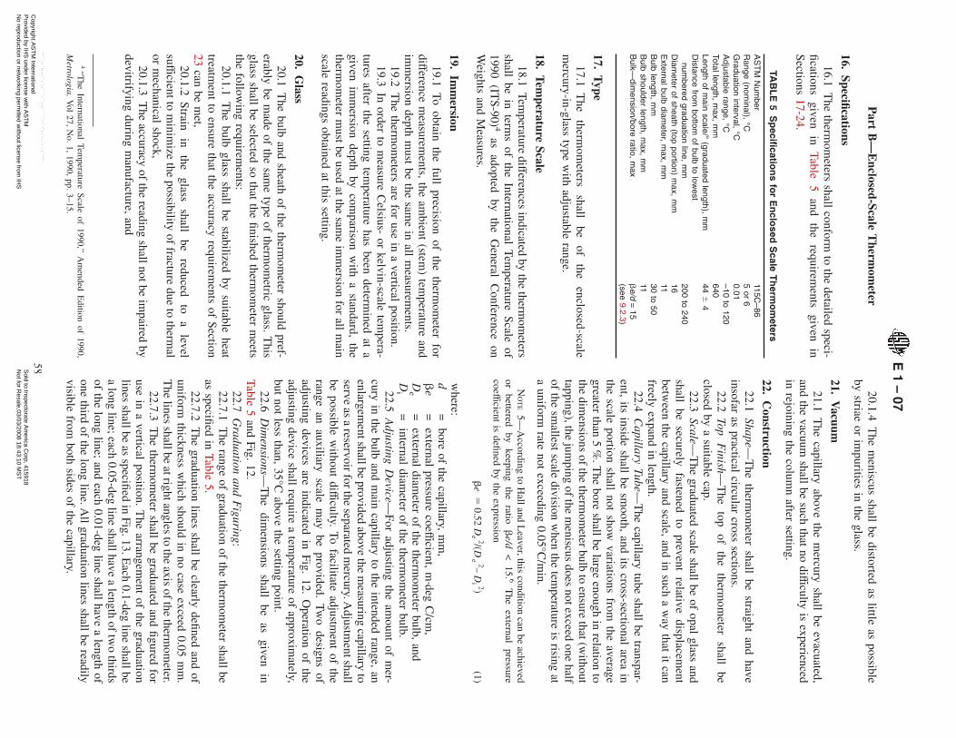
Part
B—
Enclosed-Scale
Therm
ometer
16.Specifications
16.1T
hetherm
ometers
shallconform
tothe
detailedspeci-
ficationsgiven
inTable
5and
therequirem
entsgiven
inSections
17-24.
TAB
LE
5S
pecifi
cation
sfo
rE
nclo
sedS
caleT
herm
om
eters
AS
TM
Num
ber115C
–86R
ange(nom
inal),°C
5or
6G
raduationinterval,
°C0.01
Adjustable
range,°C
–10to
120Totallength,
max,
mm
640Length
ofm
ainscale/°
(graduatedlength),
mm
446
4D
istancefrom
bottomof
bulbto
lowest
numbered
graduationline,
mm
200to
240D
iameter
ofsheath
(topportion)
max,
mm
16E
xternalbulbdiam
eter,m
ax,m
m11
Bulb
length,m
m30
to50
Bulb
shoulderlength,
max,
mm
11B
ulk—dim
ension/boreratio,
max
be/d
=15
(see9.2.3)
17.T
ype
17.1T
hetherm
ometers
shallbe
ofthe
enclosed-scalem
ercury-in-glasstype
with
adjustablerange.
18.Tem
peratureScale
18.1Tem
peraturedifferences
indicatedby
thetherm
ometers
shallbe
interm
sof
theInternational
Temperature
Scaleof
1990(IT
S-90) 4as
adoptedby
theG
eneralC
onferenceon
Weights
andM
easures.
19.Im
mersion
19.1To
obtainthe
fullprecision
ofthe
thermom
eterfor
differencem
easurements,
theam
bient(stem
)tem
peratureand
imm
ersiondepth
must
bethe
same
inall
measurem
ents.19.2
The
thermom
etersare
foruse
ina
verticalposition.
19.3In
orderto
measure
Celsius-
orkelvin-scale
tempera-
turesafter
thesetting
temperature
hasbeen
determined
ata
givenim
mersion
depthby
comparison
with
astandard,
thetherm
ometer
must
beused
atthe
same
imm
ersionfor
allm
ainscale
readingsobtained
atthis
setting.
20.G
lass
20.1T
hebulb
andsheath
ofthe
thermom
etershould
pref-erably
bem
adeof
thesam
etype
oftherm
ometric
glass.T
hisglass
shallbe
selectedso
thatthe
finishedtherm
ometer
meets
thefollow
ingrequirem
ents:20.1.1
The
bulbglass
shallbe
stabilizedby
suitableheat
treatment
toensure
thatthe
accuracyrequirem
entsof
Section23
canbe
met,
20.1.2Strain
inthe
glassshall
bereduced
toa
levelsufficientto
minim
izethe
possibilityof
fracturedue
totherm
alor
mechanical
shock,20.1.3
The
accuracyof
thereading
shallnotbeim
pairedby
devitrifyingduring
manufacture,
and
20.1.4T
hem
eniscusshall
bedistorted
aslittle
aspossible
bystriae
orim
puritiesin
theglass.
21.V
acuum
21.1T
hecapillary
abovethe
mercury
shallbe
evacuated,and
thevacuum
shallbe
suchthat
nodifficulty
isexperienced
inrejoining
thecolum
nafter
setting.
22.C
onstruction
22.1Shape—
The
thermom
etershall
bestraight
andhave
insofaras
practicalcircular
crosssections.
22.2Top
Finish—
The
topof
thetherm
ometer
shallbe
closedby
asuitable
cap.22.3
Scale—T
hegraduated
scaleshall
beof
opalglass
andshall
besecurely
fastenedto
preventrelative
displacement
between
thecapillary
andscale,
andin
sucha
way
thatit
canfreely
expandin
length.22.4
Capillary
Tube—T
hecapillary
tubeshall
betranspar-
ent,its
insideshall
besm
ooth,and
itscross-sectional
areain
thescale
portionshall
notshow
variationsfrom
theaverage
greaterthan
5%
.The
boreshall
belarge
enoughin
relationto
thedim
ensionsof
thetherm
ometer
bulbto
ensurethat(w
ithouttapping),the
jumping
ofthe
meniscus
doesnotexceed
onehalf
ofthe
smallest
scaledivision
when
thetem
peratureis
risingat
auniform
ratenot
exceeding0.05°C
/min.
NO
TE
5—A
ccordingto
Halland
Leaver,this
conditioncan
beachieved
orbettered
bykeeping
theratio
be/d
<15. 6
The
externalpressure
coefficientis
definedby
theexpression
be
50.52
De
2/~ De
2–D
i 2!(1)
where:
d=
boreof
thecapillary,
mm
,b
e=
externalpressure
coefficient,m
·degC
/cm,
De
=external
diameter
ofthe
thermom
eterbulb,
andD
i=
internaldiam
eterof
thetherm
ometer
bulb.22.5
Adjusting
Device—
Foradjusting
theam
ountof
mer-
curyin
thebulb
andm
aincapillary
tothe
intendedrange,
anenlargem
entshallbeprovided
abovethe
measuring
capillaryto
serveas
areservoir
forthe
separatedm
ercury.Adjustm
entshallbe
possiblew
ithoutdifficulty.
Tofacilitate
adjustment
ofthe
rangean
auxiliaryscale
may
beprovided.
Two
designsof
adjustingdevices
areindicated
inFig.
12.O
perationof
theadjusting
deviceshall
requirea
temperature
ofapproxim
ately,but
notless
than,35°C
abovethe
settingpoint.
22.6D
imensions—
The
dimensions
shallbe
asgiven
inTable
5and
Fig.12.
22.7G
raduationand
Figuring:
22.7.1T
herange
ofgraduation
ofthe
thermom
etershall
beas
specifiedin
Table5.
22.7.2T
hegraduation
linesshall
beclearly
definedand
ofuniform
thicknessw
hichshould
inno
caseexceed
0.05m
m.
The
linesshallbe
atrightanglesto
theaxis
ofthe
thermom
eter.22.7.3
The
thermom
etershall
begraduated
andfigured
foruse
ina
verticalposition.
The
arrangement
ofthe
graduationlines
shallbeas
specifiedin
Fig.13.Each
0.1-degline
shallbea
longline;each
0.05-degline
shallhavea
lengthof
two
thirdsof
thelong
line;and
each0.01-deg
lineshall
havea
lengthof
onethird
ofthe
longline.A
llgraduation
linesshall
bereadily
visiblefrom
bothsides
ofthe
capillary.4
“The
InternationalTem
peratureScale
of1990,”
Am
endedE
ditionof
1990,M
etrologia,V
ol27,
No.
1,1990,
pp.3–15.
E1
–07
58C
opyright AS
TM
International P
rovided by IHS
under license with A
ST
M
Sold to:Inspectorate A
merica C
orp, 415918N
ot for Resale,03/03/2008 18:43:10 M
ST
No reproduction or netw
orking permitted w
ithout license from IH
S
--``,,`,,,,``,`,,```,``,,,`````,-`-`,,`,,`,`,,`---
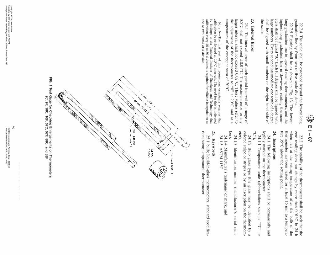
22.7.4T
hescale
shallbe
extendedbeyond
thelow
estlong
graduationline
byfrom
two
tofive
scaledivisions.
22.7.5Figuring
shallbe
asshow
nin
Fig.13.
The
lowest
longgraduation
linein
upward
readingtherm
ometers,and
thehighest
longgraduation
linein
downw
ardreading
thermom
-eters
shallbefigured
“0.”E
achfulldegree
shallbefigured
with
largenum
bers.Every
secondinterm
ediateone
tenthofa
degreeshall
befigured
with
small
numbers
onthe
right-handside
ofthe
scale.
23.Interval
Error
23.1T
heinterval
errorof
eachpartial
intervalof
arange
of0.5°C
shallnot
exceed6
0.01°C.T
hem
aximum
errorfor
anylarger
intervalshall
notexceed
0.02°C.
These
valuesrefer
tothe
adjustment
ofthe
thermom
eterto
“0”at
20°Cand
ata
temperature
ofthe
emergent
stemof
20°C.
NO
TE
6—T
hefirst
partof
thisrequirem
entessentially
requiresthat
calibrationbe
performed
at0.5°C
intervals.The
needfor
thisis
indicatedby
findingsat
theN
ationalInstitute
ofStandards
andTechnology
thatcalibration
every40
to50
divisionsis
requiredfor
reliableinterpolation
toone
ortw
otenths
ofa
division.
23.2T
hestability
ofthe
thermom
etershall
besuch
thatthe
zeroreading
doesnot
changeby
more
than0.01°C
in24
hw
henleft
atthe
settingtem
peratureafter
thebulb
ofthe
thermom
eterhas
beenheated
forat
least15
min
toa
tempera-
ture35°C
abovethe
settingpoint.
24.Inscriptions
24.1T
hefollow
inginscriptions
shallbe
permanently
andlegibly
marked
onthe
thermom
eter:24.1.1
Temperature
scale(abbreviations
suchas
“°C”
or“C
”),24.1.2
Bulb
glasstype
(theglass
may
beidentified
bya
coloredstripe
orstripes
orby
aninscription
onthe
thermom
-eter),
24.1.3Identification
number
(manufacturer’s
serialnum
-ber),
24.1.4M
anufacturer’stradenam
eor
mark,
and24.1.5
AST
M115C
.
25.K
eywords
25.1bulb;
liquid-in-glasstherm
ometers;
standardspecifica-
tion;stem
;tem
perature;therm
ometer
FIG
.1
TestG
age
for
Ch
ecking
En
largem
ents
on
Th
ermo
meters
9C,
9F,10C
,10F,
57C,
57F,88C
,an
d88F
E1
–07
59C
opyright AS
TM
International P
rovided by IHS
under license with A
ST
M
Sold to:Inspectorate A
merica C
orp, 415918N
ot for Resale,03/03/2008 18:43:10 M
ST
No reproduction or netw
orking permitted w
ithout license from IH
S
--``,,`,,,,``,`,,```,``,,,`````,-`-`,,`,,`,`,,`---
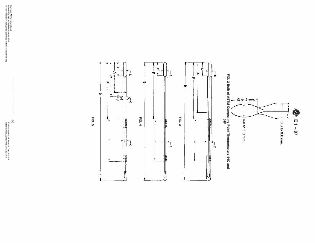
FIG
.2
Bu
lbo
fA
ST
MC
on
gealin
gP
oin
tT
herm
om
eters54C
and
54F
FIG
.3
FIG
.4
FIG
.5
E1
–07
60C
opyright AS
TM
International P
rovided by IHS
under license with A
ST
M
Sold to:Inspectorate A
merica C
orp, 415918N
ot for Resale,03/03/2008 18:43:10 M
ST
No reproduction or netw
orking permitted w
ithout license from IH
S
--``,,`,,,,``,`,,```,``,,,`````,-`-`,,`,,`,`,,`---

FIG
.6
FIG
.7
FIG
.8
FIG
.9
E1
–07
61C
opyright AS
TM
International P
rovided by IHS
under license with A
ST
M
Sold to:Inspectorate A
merica C
orp, 415918N
ot for Resale,03/03/2008 18:43:10 M
ST
No reproduction or netw
orking permitted w
ithout license from IH
S
--``,,`,,,,``,`,,```,``,,,`````,-`-`,,`,,`,`,,`---

FIG
.10
FIG
.11
E1
–07
62C
opyright AS
TM
International P
rovided by IHS
under license with A
ST
M
Sold to:Inspectorate A
merica C
orp, 415918N
ot for Resale,03/03/2008 18:43:10 M
ST
No reproduction or netw
orking permitted w
ithout license from IH
S
--``,,`,,,,``,`,,```,``,,,`````,-`-`,,`,,`,`,,`---

NO
TE
1—A
lldim
ensionsare
inm
illimetres.
FIG
.12
En
closed
Scale
Ad
justab
leR
ang
eT
herm
om
eters
FIG
.13
Grad
uatio
nan
dF
igu
ring
E1
–07
63C
opyright AS
TM
International P
rovided by IHS
under license with A
ST
M
Sold to:Inspectorate A
merica C
orp, 415918N
ot for Resale,03/03/2008 18:43:10 M
ST
No reproduction or netw
orking permitted w
ithout license from IH
S
--``,,`,,,,``,`,,```,``,,,`````,-`-`,,`,,`,`,,`---

AS
TM
Internationaltakesno
positionrespecting
thevalidity
ofany
patentrights
assertedin
connectionw
ithany
itemm
entionedin
thisstandard.U
sersofthis
standardare
expresslyadvised
thatdetermination
ofthevalidity
ofanysuch
patentrights,andthe
riskof
infringement
ofsuch
rights,are
entirelytheir
own
responsibility.
This
standardis
subjecttorevision
atanytim
eby
theresponsible
technicalcomm
itteeand
mustbe
reviewed
everyfive
yearsand
ifnotrevised,eitherreapprovedorw
ithdrawn.Y
ourcomm
entsare
invitedeitherforrevision
ofthisstandard
orforadditionalstandardsand
shouldbe
addressedto
AS
TM
InternationalHeadquarters.Y
ourcom
ments
willreceive
carefulconsiderationata
meeting
oftheresponsible
technicalcomm
ittee,w
hichyou
may
attend.If
youfeelthat
yourcom
ments
havenot
receiveda
fairhearing
youshould
make
yourview
sknow
nto
theA
ST
MC
omm
itteeon
Standards,
atthe
addressshow
nbelow
.
This
standardis
copyrightedby
AS
TM
International,100B
arrH
arborD
rive,PO
Box
C700,W
estConshohocken,P
A19428-2959,
United
States.
Individualreprints
(singleor
multiple
copies)of
thisstandard
may
beobtained
bycontacting
AS
TM
atthe
aboveaddress
orat
610-832-9585(phone),
610-832-9555(fax),
orservice@
astm.org
(e-mail);
orthrough
theA
ST
Mw
ebsite(w
ww
.astm.org).
FIG
.14
Sch
emes
for
Grad
uatio
nan
dF
igu
ring
E1
–07
64C
opyright AS
TM
International P
rovided by IHS
under license with A
ST
M
Sold to:Inspectorate A
merica C
orp, 415918N
ot for Resale,03/03/2008 18:43:10 M
ST
No reproduction or netw
orking permitted w
ithout license from IH
S
--``,,`,,,,``,`,,```,``,,,`````,-`-`,,`,,`,`,,`---
![Precision Thermometers for Material Testing€¦ · ASTM like thermometers Blue filling. Type. ASTM [*] The accuracy acc. to ASTM Standard by these types cannot be maintained over](https://static.cupdf.com/doc/110x72/6091d61515d1b743c219679b/precision-thermometers-for-material-testing-astm-like-thermometers-blue-filling.jpg)