ADAMA SCIENCE AND TECHNOLOGY UNIVERSITY School of Mechanical, Chemical and Materials Engineering
Design and Manufacturing of Concrete Mixing Machine
A Project submitted in partial fulfillment of the requirements for the award of the degree of
Master of Science in
Manufacturing Technology Teachers’ Education
By Abebe Wube GSR/5252/06
Bayuo Yilma GSR/5257/06
Gemta Alemu GSR/5266/06
Tadele Worku GSR/5278/06
Major Advisor: Dr. Habtamu Beri Co-Advisor: Ato. Dagmawi Hailu
Department of Manufacturing and Vehicle Engineering May, 2015
Adama

ADAMA SCIENCE AND TECHNOLOGY UNIVERSITY
School of Mechanical, Chemical and Materials Engineering
Department of Manufacturing and Vehicle Engineering
Design and Manufacturing of Concrete Mixing Machine
By
Abebe Wube GSR/5252/06
Bayuo Yilma GSR/5257/06
Gemta Alemu GSR/5266/06
Tadele Worku GSR/5278/06
Approved by Board of Examiners
_________________________________ ___________ ____________ Chairman, Department Graduate Committee Signature Date _________________________________ ___________ ____________ Internal Examiner Signature Date _________________________________ ___________ ____________ External Examiner Signature Date _________________________________ ___________ ____________ Advisor Signature Date

i
DECLARATION
We hereby declare that the work which is being presented in the project entitled
“Design and Manufacturing of Concrete Mixing Machine” in partial fulfillment of
the requirements for the award of the degree of Master of Science in Manufacturing
Technology of Technical Teachers’ Education is an authentic record of our own
work carried out from March 2015 to May 2015 under the supervision of School of
Mechanical and Chemical Engineering, Department of Mechanical and Vehicle
Engineering, Adama Science and Technology University, Adama-Ethiopia.
The matter embodied in this project has not been submitted by us or others for the
award of any other degree or diploma. All relevant resources of information used in
this thesis have been duly acknowledged.
Abebe Wube ______________________ _______________
Bayou Yilma ______________________ _______________
Gemta Alemu ______________________ _______________
Tadele Worku ______________________ _______________
Student Signature Date This is to certify that the above statement made by the candidates is correct to the
best of my knowledge and belief. This project has been submitted for examination
with my approval.
Dr. Habtamu Beri __________________ _________________
Advisor Signature Date

ii
Acknowledgements
This project work could not have been completed without the support and
encouragement of several people. We are highly indebted to our advisor,
Habtamu Beri (PhD), Dean for Research Affairs, Adama Science and
Technology University, Adama, for his excellent and sustainable direction,
invaluable feedback, constructive suggestions, detailed corrections, support
and encouragement that played enormous role resulted for the successful
accomplishment of this project.
We would like to extend our gratitude to our Co-advisor Ato Dagmawi Hailu,
School of Mechanical and Chemical Engineering, Associate dean for
Administrative Affairs, Lecturer in mechanical and vehicle engineering
department of ASTU, who played his part in providing us valuable direction
both in theoretical and practical staring from the very beginning of the work.
The efforts of all mechanical and vehicle engineering department workers and
school of mechanical and chemical engineering are also highly appreciated and
acknowledged. Tekleberhan Amabaye and Afrotsion construction contractors’
organization and SME for construction works workers, supervisors and mixer
machine operators are also peoples who supported us in providing valuable
information from Adama town.
We also own thanks and appreciation to Ato Adebabay Hailu and Asnakech
Gudeta for their support and encouragement during the process of
accomplishment of this project.
Furthermore, we would like to extend our thanks to ASTU tool men, for their
cooperation in using machineries, hand tools and work shop to finalize our
project.
Finally, this effort would not be possible without each of our families; their
efforts and sacrifices that have been helped great towards the completion of
this project.

iii
Table of Contents
Contents Pages
DECLARATION ................................................................................................. i
Acknowledgements .......................................................................................... ii
Table of Contents ........................................................................................... iii
List of Tables .................................................................................................. vi
List of Figures .............................................................................................. vii
Abbreviations and Acronyms ........................................................................ viii
Abstract ........................................................................................................ ix
CHAPTER ONE
INTRODUCTION 1
1.1. Background ............................................................................................ 1
1.2. Statement of the problem ........................................................................ 3
1.3. Objectives ............................................................................................... 5
1.3.1 General objective .................................................................................. 5
1.3.2.Specific objectives ................................................................................. 5
1.4. Significance of the project ........................................................................ 5
1.5. Scope of the project ................................................................................. 5
1.6. Limitations ............................................................................................. 6
CHAPTER TWO
REVIEW OF LITERATURE 7
2.1 Introduction ............................................................................................. 7
2.2 Onsite and portable concrete mixers ………………………………………………….. 7
2.3 Hardware ..................................................................................................... 9
2.3.1 Batch Mixers ......................................................................................... 9
2.3.1.1 Drum Mixers ................................................................................. 9
2.3.1.2 Pan Mixers................................................................................... 12
2.3.2 Continuous Mixers .............................................................................. 12
2.4 Mixing Method ........................................................................................... 13
2.4.1 Loading, Mixing and Discharging .......................................................... 13
2.4.2 Mixing Energy ..................................................................................... 15
2.5 Mixer Efficiency ......................................................................................... 15
2.5.1 Performance Attributes as indicators of efficiency .................................. 16
2.5.2 Composition as an indicator of efficiency 16

iv
2.5.3 Hybrid: Composition and performance as joint indicators of efficiency 17
2.5.4 Output rate as an indicator of efficiency 19
2.6 Mixing energy 19
2.7 Wear and Tear 21
CHAPTER THREE
MATERIALS AND METHODOLOGY 22
3.1 Instrument Development ............................................................................ 22
3.2 Sample Selection ....................................................................................... 22
3.3 Data Collection .......................................................................................... 23
3.3.1 Survey questionnaire ..................................................................... 24
3.3.2 Interview ...................................................................................... 24
3.3.3 Direct Observation .......................................................................... 25
3.4 Data Analysis and Interpretation ................................................................ 25
CHAPTER FOUR
DESIGN ANALYSIS AND MATERIAL SELECTION 27
4.1 Introduction ............................................................................................. 27
4.2 Material Selection Process and its factor .................................................... 29
4.2.1 Material Selection for significant parts or components .......................... 31
4.2.1.1 Material Selection for Shafts ..................................................... 31
4.2.1.2 Material Selection for larger pulley ............................................ 33
4.2.1.3 Material Selection for bearing house ......................................... 37
4.2.1.4 Standard bearing ..................................................................... 37
4.3 Design of critical components ..................................................................... 38
4.3.1 Design of driver shaft .......................................................................... 39
4.3.2 Design of pulley .................................................................................. 51
4.3.3 Determination of belt length ................................................................ 54
4.4 Ergonomic Consideration 68
CHAPTER FIVE
MANUFACTURING PROCESS AND ASSEMBLING 70
5.1 Manufacturing Process 70
5.1.1 General steps to manufacture components of the machine 70
5.2 Assembling Procedure 80
v
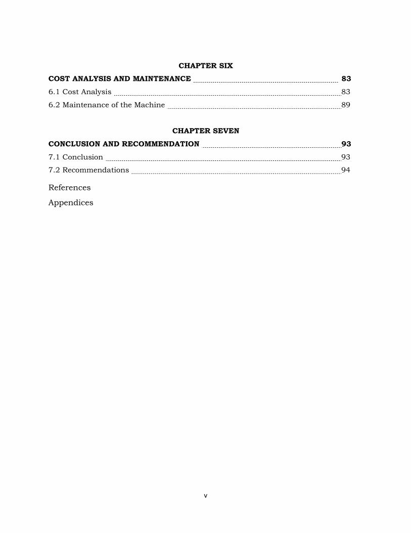
CHAPTER SIX
COST ANALYSIS AND MAINTENANCE 83
6.1 Cost Analysis 83
6.2 Maintenance of the Machine 89
CHAPTER SEVEN
CONCLUSION AND RECOMMENDATION 93
7.1 Conclusion 93
7.2 Recommendations 94
References
Appendices
vi
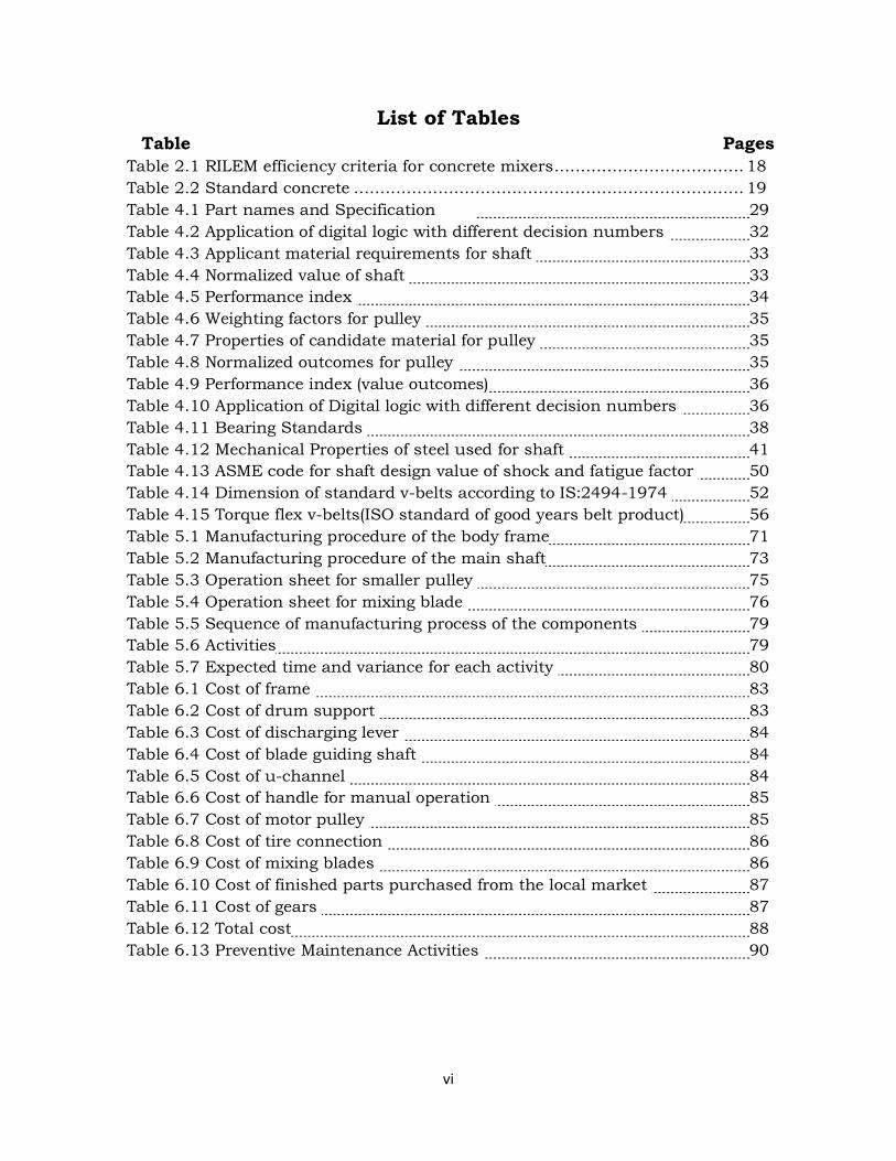
List of Tables Table Pages
Table 2.1 RILEM efficiency criteria for concrete mixers .................................... 18
Table 2.2 Standard concrete .......................................................................... 19
Table 4.1 Part names and Specification 29
Table 4.2 Application of digital logic with different decision numbers 32
Table 4.3 Applicant material requirements for shaft 33
Table 4.4 Normalized value of shaft 33
Table 4.5 Performance index 34
Table 4.6 Weighting factors for pulley 35
Table 4.7 Properties of candidate material for pulley 35
Table 4.8 Normalized outcomes for pulley 35
Table 4.9 Performance index (value outcomes) 36
Table 4.10 Application of Digital logic with different decision numbers 36
Table 4.11 Bearing Standards 38
Table 4.12 Mechanical Properties of steel used for shaft 41
Table 4.13 ASME code for shaft design value of shock and fatigue factor 50
Table 4.14 Dimension of standard v-belts according to IS:2494-1974 52
Table 4.15 Torque flex v-belts(ISO standard of good years belt product) 56
Table 5.1 Manufacturing procedure of the body frame 71
Table 5.2 Manufacturing procedure of the main shaft 73
Table 5.3 Operation sheet for smaller pulley 75
Table 5.4 Operation sheet for mixing blade 76
Table 5.5 Sequence of manufacturing process of the components 79
Table 5.6 Activities 79
Table 5.7 Expected time and variance for each activity 80
Table 6.1 Cost of frame 83
Table 6.2 Cost of drum support 83
Table 6.3 Cost of discharging lever 84
Table 6.4 Cost of blade guiding shaft 84
Table 6.5 Cost of u-channel 84
Table 6.6 Cost of handle for manual operation 85
Table 6.7 Cost of motor pulley 85
Table 6.8 Cost of tire connection 86
Table 6.9 Cost of mixing blades 86
Table 6.10 Cost of finished parts purchased from the local market 87
Table 6.11 Cost of gears 87
Table 6.12 Total cost 88
Table 6.13 Preventive Maintenance Activities 90

vii
List of Figures Figure Pages
Figure 2.1 Portable site concrete mixer ............................................................................ 8
Figure 2.2 An outdated model a small scale concrete mixer. ............................................ 9
Figure 2.3 Cross section of drum. .................................................................................. 10
Figure 2.4 Cross section of non tilting mixer ................................................................. 11
Figure 2.5 Cross section of a tilting mixer ............................................................ 11
Figure 2.6 Various Configuration for pan mixers ........................................................... 13
Figure 2.7 Mixing Schedule ............................................................................................ 14
Figure 4.1 Material selection process for a machine part 30
Figure 4.2 Shaft assemblies with pulley and bearing 39
Figure 4.3 Twisting moment of torque of shaft 43
Figure 4.4 Shear force diagram for shaft 43
Figure 4.5 Bending moment acting on the shaft 44
Figure 4.6 Bending moment acting on the shaft @xz plane 45
Figure 4.7 Shear force of magnitude xz plane 45
Figure 4.8 Magnitude of bending moment @yz plane 46
Figure 4.9 Magnitude of bending moment 47
Figure 4.10 Deflection of the shaft 47
Figure 4.11 Free body diagram of force analysis on the pulley 53
Figure 4.12 Belt Drivers 55
Figure 4.13 Belt Tension 57
Figure 4.14 Force acting on the key 58
Figure 4.15 Force analysis of gear 63
Figure 4.16 Radial arm length of the shaft 66
Figure 5.1 Frame of the machine 71
Figure 5.2 Main shaft 72
Figure 5.3 Larger pulley 74
Figure 5.4 Smaller (motor) pulley 74
Figure 5.5 Mixing Blade 75
Figure 5.6 Spur gear 76
Figure 5.7 Standard bearing houses 78
Figure 5.8 Isometric drawing of the project 81

viii
LIST OF ABBREVIATIONS AND ACRONYMS
AC: Alternate Current
ASME: American Society of Mechanical Engineering
ASTU: Adama Science and Technology University
COV: Coefficient of Variation
DC: Direct Current
HRWRA: High Range Water Reducer Admixture
RILEM: Re’union International des Laboratories d’ Essais et de
Recherches sur les Mate’riaux et les constructions
RPM: Revolution per Minute
SEM: Scanning Electron Microscope
SME: Small and Micro Enterprise
TVET: Technical and Vocational Education and Training
WF: Weight Factor

ix
Abstract
A typical concrete mixer uses a revolving drum to mix the components. Mixing
concrete is a combining process in which aggregate/gravels, grits, stone chips,
cement and water is revolving up and down using radial or centrifugal force and
mix simultaneously in a drum to make concrete. Concrete is a substance used for
building and construction industry which is made by the mixture of cement,
stone chips, and water. Now a day concrete mixing process using mixer machine
can be time saving and applicable in every construction sites from small scale to
large scale level. Small scale construction enterprises are owned by individual
entrepreneurs, firms, and shareholders currently involved in fabrication of dam,
irrigation and etc. and thus the mixer we produced considered as its efficiency is
good, the machine performance and mixing time is 150-200kg with in 10min or
930 kg per hour. When using manual, the human power delivered to 50kg in 10
min mixing rate is minimized from relative to the power.
Construction site workers expressed their feeling through questionnaire we
provided them if their organization can get mixer machine with a reasonable
price for the ease of mixing. According to their response most of the time they are
mixing or producing concrete by the oldest method, which is using shovel. In this
(oldest method) operation the time required to provide concrete is much greater
than expected and uses more and more manpower. Therefore, to make the gap
narrower we made a design and produced the machine with local materials,
easily movable mechanisms, optional operation design that is using manual in
operation with the machine when electric power is interrupted without the delay
of mixing time and etc in order to produce homogenous mixture of concrete with
very attractive and reasonable selling price of 24,844.215 Ethiopian birr. The
machine was tested for its functionality and no unexpected or exaggerated
problem is observed except machining speed variation than expected using three
phase 2hp electric motor. Meaning the speed is slightly higher than designed and
we recommend using electric motor of lesser power or hp. If urban and rural
development experts at different levels and stakeholders create awareness for
easy dissemination of the technology in to rural areas because the machine was
designed to work electrically and manually, part of the problems of construction
and building industry may be minimized as our understanding.
Key words:- Concrete mixer, mixer efficiency, homogenous mixture etc.

1
CHAPTER ONE
INTRODUCTION
1.1 Background of the Study
Some form of concrete, the mix of a binder, aggregate and water, has existed since
the dynasties of the Egyptian pharaohs when water, sand and lime were mixed to
use as mortar in building sections of the pyramids. Romans also used a form of
concrete in constructing their aqueducts, the Coliseum and other major
constructions. Scientists in the 1800s began experimenting and perfecting
hydraulic cement, which is what the construction industry still uses today. The
name for Portland cement came from the Isle of Portland, off the English coast,
where deposits of the mineral components used in modern concrete were first found
and chemically isolated. By 1908, Thomas Edison was experimenting with building
pre-cast concrete houses in Union, N.J. Most of those houses are still standing and
being used. Then there are the famed Hoover and Grand Coulee dams, built in
1936, that stand among the wonders of the world.
Stephen Stepanian developed and applied to patent the first motorized transit mixer
in 1916, in an effort to replace the horse-drawn concrete mixer used at the time.
Wooden paddles churned the mixture as the cart wheels turned, but the design was
of limited use. It was cumbersome and slow. The same, however, could be said of
the engines and trucks during that period. But by the 1940s, engines and truck-
frame construction caught up to the need for a rugged vehicle capable of hauling
thousands of pounds of wet, or unset, concrete. As the building boom following
World War II went into full swing, mixer trucks came into their own.
The large drum mixer seen on roads today hasn't changed much from Stephanie’s
vision of a better concrete hauler. Mobile transit mixers are a mix-and-match
selection of engine, truck frame and rotating mixer. The mixer is similar, though
larger in scale, than the smaller ones found on construction sites. A large motor,
separate from the engine, rotates the drum on the truck body, and a series of
blades or a screw powered by the same motor keeps the aggregate, water and

2
cement in constant motion. This keeps the premixed concrete from setting, though
the clock is often ticking to get the load to the construction site, road section or
parking lot. Most cement manufacturers suggest keeping the time between mixing
and pouring to 90 minutes at most. It's even better to get it to the site in less than
an hour.
As technology has changed, so has the basic mixer design. While many transit
mixers still have rotating drums, most don't simply pick up a load of wet cement
and transport it.
Most transit mixers have a separate water tank in the truck. The spinning drum
keeps the dry ingredients, aggregate and cements mixing during most of the trip.
When the driver is within a few miles of the site, water is added to create concrete
fresh for delivery.
This is considered "batch" delivery of ready-mixed concrete, mixing ingredients off
site and trucking them where they're needed. Advances in technology have made it
possible to mix concrete at the job site, though transit mixers are still the
workhorse of the field.
Volumetric and metered mixers are becoming more common. Both types are
essentially on-site custom concrete plants. Separate holding tanks of aggregate,
cement and water are contained in one truck with a computer hooked to augers
and pumps. At the site, the customer can order a specific type of concrete (there are
more than a dozen) that can be mixed by the truck.
Volumetric and metered mixers are often used during high-rise construction and
can be paired with pumper trucks to deliver concrete more than 15 stories above
the ground.
A concrete mixer also commonly called a cement mixer is a device that
homogeneously combines cement, aggregate such as sand or gravel, and water to
form concrete. A typical concrete mixer uses a revolving drum to mix the
components. For smaller volume works portable concrete mixers are often used so
that the concrete can be made at the construction site, giving the workers ample

3
time to use the concrete before it hardens. An alternative to a machine is mixing
concrete by hand. This is usually done in a wheelbarrow; however, several
companies have recently begun to use modified tarps for this purpose.
Concrete is mixed either by hand or machine. No matter which method is used, one
must follow well-established procedures if expected finished concrete of good
quality. But an oversight in proper concrete mixing, whether through lack of
competence or inattention to detail, cannot be corrected later. Therefore, in order
for proper mixing procedure it is advisable to use the right mixing machine. Based
on the above fact we are going to manufacture a well adjusted and easily affordable
and even manageable through electrical and manually operated concrete mixer for
the construction industry.
1.2 Statement of the problem
With the development and transformation of society from a global
perspective concrete mixer development, in the early stages of industrial, concrete
mixer manufacturing industry is the main industry; and in the middle and late
industrialization, services gradually become the main industry. Today, concrete
mixing machine companies have entered a "post-industrial era", relying on the
advantages of brand and manufacturing services and other charges in the global
high-end market advantage.
Mini concrete mixer companies build service system, not just in improving
hardware and management level, more importantly, efforts to improve the quality of
personnel concrete mixer equipment marketing and technical services team, the
company initiated a "customer first" and for customers to create the greatest value
of the concept, the combination of the depth of manufacturing and services.
Innovation around the core product or core competencies, and service combine to
achieve better development. Thus in our country concrete mixer machine was
imported from the developed countries with high amount of foreign currency cost,
either heavy or small duty concrete mixer machine except Kality metal work factory,
Abe engineering(Adama), and defence engineering found in Ethiopia are producing
it with 100% copying. Still there is no an appropriate modification and production

4
of mixer related to cost reduction phenomena. This is happened by various factors,
like the privation of appropriate technology related to produce concrete mixer
machine in domestic level, the machine required complex manufacturing process,
maintainability, operation, well trained man power etc. so the micro enterprise and
TVET institution are not engaged in producing concrete mixing machine.
Our project is expected to find solution for the problems occurred in small scale
construction enterprises in making concrete rather than traditional way and to
improve the quality of concrete by avoiding dusts and impurities that could be
mixed during mixing. Most construction workers mix concrete on the floor using
shovel due to unavailability of proper mixing machine. The concrete obtained by
this process lack quality and homogenous mixture.
We modified the existing concrete mixer due to the following;
Machines require high cost either to purchase or manufacture.
The time required in regulating and setting the machine is comparatively
higher.
There was no study made to produce or manufacture the machine in TVET and
by most micro enterprise workshops.
It is difficult or need some load carrying machines or cars to move from place
to place.
Therefore, in order to minimize the stated problems above we produced a tilt
drum type concrete mixer machine.
1.3 Objectives
1.3.1 General Objective
The overall objective of this project is to improve the design, size, maintenance and
Manufacturing of a concrete mixing machine.
5
1.3.2 Specific objectives
The following are the specific objectives of the project:
- Identify problems related to the machines based on suppliers and users
feed-back.
- To produce a machine with a minimum cost
- To select materials according to the specification
- To select manufacturing process suitable for the project
- To Inspect and test the project to ensure its functionality
1.4 Significance of the study The concrete mixer we produced can have several purposes when compared to the
other and heavy duty mixer machine: therefore, it is:
Easy to operate
Lesser maintenance
Easy to move from place to place
Easy to produce and transfer to small and medium scale enterprises.
It is easy to operate, durable and have a longer functional life. It has a lesser
cost of maintenance and will be available in the leading industrial price if
transferred to SME.
1.5 Scope of the Project
We designed and manufactured manual and electrically operated concrete mixing
machine. The mixing process can be set electrically using 2hp single phase electric
motor and manually by free hand with the help of crank shaft or, in short, handle
when an electric power is not available in the site by considering human ergonomic
factors. Our target community for a proof-of-concept design is the construction
center or industry or small scale micro enterprise (MSE) and private construction
industry engaged in production of concrete for building or construction purpose.

6
1.6 Limitations
Budget constraint is one of the problems we faced to start the project on time in
order to complete successfully within the schedule of the university. Besides,
shortage of raw materials in the market and time constraints due to unpredicted
occasions existed is the other. Searching for the right material and standards from
local market and unavailability and poor working conditions of machines also taken
much time and money than we expected. We added some amount to what we
budgeted due to transportation cost for looking the right materials and standards
(from Adama and Addis Ababa) and inflation of materials’ price are some of the
limitations we faced.

7
CHAPTER TWO
REVIEW OF LITERATURE
2.1 Introduction
As for all materials, the performance of concrete is determined by its
microstructure. Its microstructure is determined by its composition, its curing
conditions, and also by the mixing method and mixer conditions used to process
the concrete. The mixing procedure includes the type of mixer, the order of
introduction of the materials into the mixer, and the energy of mixing (duration and
power). To control the workability of the fresh concrete, for example, it is important
to control how the concrete is processed during manufacture.
In this overview, the different mixers commercially available have been presented
together with a review of the mixing methods. Further, the advantages and
disadvantages of the different mixers and mixing methods and their application
were examined. A review of mixing methods in regards to the quality of the concrete
produced and some procedures used to determine the effectiveness of mixing
methods were also given.
The methodology to determine the quality of the concrete mixed is often referred to
as the measurement of the efficiency of the mixer. The efficiency parameters of a
mixer are affected by the order in which the various constituents of the concrete are
introduced into the mixer, the type of mixer, and the mixing energy (power and
duration) used.
2.2 On-site and portable concrete mixers
For smaller jobs, such as residential repairs, renovations, or hobbyist-scale
projects, many cubic yards of concrete are usually not required. Bagged cement is
readily available in small-batch sizes and aggregate and water is easily obtained in
small quantities for the small work site. To service this small-batch concrete
market, there are many types of small portable concrete mixers available.
A typical portable concrete mixer uses a small revolving drum to mix the
components. For smaller jobs the concrete made at the construction site has no

8
time lost in transport, giving the workers ample time to use the concrete before it
hardens.
Portable concrete mixers may be powered by a gasoline engine, although it is more
common that they are powered by electric motors using standard mains current.
These concrete mixers are further divided based on their loading mechanism.
Cement, sand and other aggregates are loaded in a hydraulically operated hopper
and then poured in the mixing drum for final mixing and then can be unloaded by
tilting the drum. While in Hand Feed Concrete Mixers, cement, sand and other
aggregates are directly added to the mixing drum manually. These both type of
concrete mixers are highly popular and used in regular construction activities in
Africa, some Middle Eastern Countries and in the Indian subcontinent.
Figure 2.1 Portable site concrete mixer[15]
This portable concrete/mortar mixer has wheels and a towing tongue so that it can
be towed by a motor vehicle and moved around the worksite by hand, and its
rotation is powered by mains electricity. The lever allows the concrete/mortar to be
tipped into a wheelbarrow.

9
Figure 2.2 An outdated model of a small scale concrete mixer[15]
These older mixers are heavy and cannot be moved as easily. They are still self
powered with an electric motor.
2.3 Hardware: the Mixers
There are two main categories of mixer: batch mixers and continuous mixers. The
first type of mixer produces concrete one batch at a time, while the second type
produces concrete at a constant rate. The first type needs to be emptied completely
after each mixing cycle, cleaned (if possible), and reloaded with the materials for the
next batch of concrete. In the second type, the constituents are continuously
entered at one end as the fresh concrete exits the other end. The various designs of
each type of mixer will now be discussed.
2.3.1 Batch Mixers
Two main types of batch mixer can be distinguished by the orientation of the axis of
rotation: horizontal or inclined (drum mixers) or vertical (pan mixers). The drum
mixers have a drum, with fixed blades, rotating around its axis, while the pan
mixers may have either the blades or the pan rotating around the axis.
2.3.1.1 Drum Mixers
All the drum mixers have a container with a cross section similar to that shown in
Figure 2.3. The blades are attached to the inside of the movable drum. Their main
purpose is to lift the materials as the drum rotates. In each rotation, the lifted
material drops back into the mixer at the bottom of the drum and the cycle starts
again. Parameters that can be controlled are the rotation speed of the drum and, in
certain mixers, the angle of inclination of the rotation axis. There are three main
types of drum mixers:
• non-tilting drum;
10
• reversing drum;
• tilting drum.
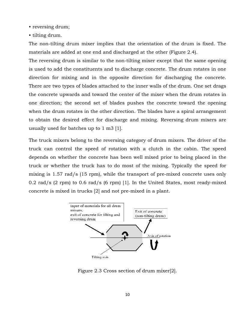
The non-tilting drum mixer implies that the orientation of the drum is fixed. The
materials are added at one end and discharged at the other (Figure 2.4).
The reversing drum is similar to the non-tilting mixer except that the same opening
is used to add the constituents and to discharge concrete. The drum rotates in one
direction for mixing and in the opposite direction for discharging the concrete.
There are two types of blades attached to the inner walls of the drum. One set drags
the concrete upwards and toward the center of the mixer when the drum rotates in
one direction; the second set of blades pushes the concrete toward the opening
when the drum rotates in the other direction. The blades have a spiral arrangement
to obtain the desired effect for discharge and mixing. Reversing drum mixers are
usually used for batches up to 1 m3 [1].
The truck mixers belong to the reversing category of drum mixers. The driver of the
truck can control the speed of rotation with a clutch in the cabin. The speed
depends on whether the concrete has been well mixed prior to being placed in the
truck or whether the truck has to do most of the mixing. Typically the speed for
mixing is 1.57 rad/s (15 rpm), while the transport of pre-mixed concrete uses only
0.2 rad/s (2 rpm) to 0.6 rad/s (6 rpm) [1]. In the United States, most ready-mixed
concrete is mixed in trucks [2] and not pre-mixed in a plant.
Figure 2.3 Cross section of drum mixer[2].
11
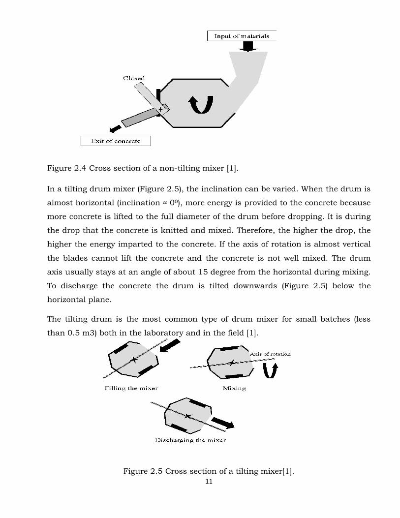
Figure 2.4 Cross section of a non-tilting mixer [1].
In a tilting drum mixer (Figure 2.5), the inclination can be varied. When the drum is
almost horizontal (inclination ≈ 00), more energy is provided to the concrete because
more concrete is lifted to the full diameter of the drum before dropping. It is during
the drop that the concrete is knitted and mixed. Therefore, the higher the drop, the
higher the energy imparted to the concrete. If the axis of rotation is almost vertical
the blades cannot lift the concrete and the concrete is not well mixed. The drum
axis usually stays at an angle of about 15 degree from the horizontal during mixing.
To discharge the concrete the drum is tilted downwards (Figure 2.5) below the
horizontal plane.
The tilting drum is the most common type of drum mixer for small batches (less
than 0.5 m3) both in the laboratory and in the field [1].
Figure 2.5 Cross section of a tilting mixer[1].
12
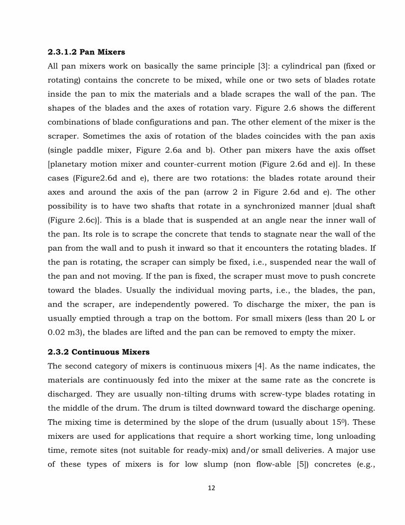
2.3.1.2 Pan Mixers
All pan mixers work on basically the same principle [3]: a cylindrical pan (fixed or
rotating) contains the concrete to be mixed, while one or two sets of blades rotate
inside the pan to mix the materials and a blade scrapes the wall of the pan. The
shapes of the blades and the axes of rotation vary. Figure 2.6 shows the different
combinations of blade configurations and pan. The other element of the mixer is the
scraper. Sometimes the axis of rotation of the blades coincides with the pan axis
(single paddle mixer, Figure 2.6a and b). Other pan mixers have the axis offset
[planetary motion mixer and counter-current motion (Figure 2.6d and e)]. In these
cases (Figure2.6d and e), there are two rotations: the blades rotate around their
axes and around the axis of the pan (arrow 2 in Figure 2.6d and e). The other
possibility is to have two shafts that rotate in a synchronized manner [dual shaft
(Figure 2.6c)]. This is a blade that is suspended at an angle near the inner wall of
the pan. Its role is to scrape the concrete that tends to stagnate near the wall of the
pan from the wall and to push it inward so that it encounters the rotating blades. If
the pan is rotating, the scraper can simply be fixed, i.e., suspended near the wall of
the pan and not moving. If the pan is fixed, the scraper must move to push concrete
toward the blades. Usually the individual moving parts, i.e., the blades, the pan,
and the scraper, are independently powered. To discharge the mixer, the pan is
usually emptied through a trap on the bottom. For small mixers (less than 20 L or
0.02 m3), the blades are lifted and the pan can be removed to empty the mixer.
2.3.2 Continuous Mixers
The second category of mixers is continuous mixers [4]. As the name indicates, the
materials are continuously fed into the mixer at the same rate as the concrete is
discharged. They are usually non-tilting drums with screw-type blades rotating in
the middle of the drum. The drum is tilted downward toward the discharge opening.
The mixing time is determined by the slope of the drum (usually about 150). These
mixers are used for applications that require a short working time, long unloading
time, remote sites (not suitable for ready-mix) and/or small deliveries. A major use
of these types of mixers is for low slump (non flow-able [5]) concretes (e.g.,

13
pavements). Due to the short mixing time, the air content is not easily controlled
even with the addition of air entraining admixtures [6].
Figure 2.6 Various configurations for pan mixers. The arrows indicate the direction of rotation of the pan, blades, and scraper[6]. 2.4 Mixing Method
In describing the mixing process, the mixer hardware is only one of several
components. The mixing process also includes the loading method, the discharge
method, the mixing time, and the mixing energy.
2.4.1 Loading, Mixing, and Discharging
The loading method includes the order of loading the constituents into the mixer
and also the duration of the loading period. The duration of this period depends on
how long the constituents are mixed dry before the addition of water and how fast
the constituents are loaded.
The loading period is extended from the time when the first constituent is
introduced in the mixer to when all the constituents are in the mixer. RILEM
(Re´union Internationale des Laboratoires d’Essais et de Recherches sur les
Mate´riaux et les constructions) [8] divides the loading period into two parts: dry
mixing and wet mixing (Figure 2.7). Dry mixing is the mixing that occurs during

14
loading but before water is introduced. Wet mixing is the mixing after or while water
is being introduced, but still during loading. This means that materials are
introduced any time during the loading period: all before the water, all after the
water, partially before and partially after.
Figure 2.7 Mixing schedule ([8] for further discussion of this graph). The loading period is important because some of the concrete properties will depend
on the order in which the constituents are introduced in the mixer. It is well known
that the delayed addition of high range water reducer admixture (HRWRA) leads to a
better dispersion of the cement. The same workability can be thus being achieved
with a lower dosage of HRWRA [7]. Unfortunately, there is no systematic study, to
our knowledge, that has examined the influence of the order of constituent loading
on concrete properties. Most operators rely on experience and trial and error to
determine the loading order of their mixer.
Very often, the mixing time is defined as the time elapsed between the loadings of
the first constituent to the final discharge of the concrete. RILEM [8] took another
approach defining mixing time as the time between the loading of all constituents

15
and the beginning of concrete discharge (Figure 2.7). It should be noted that solid
constituents can be added at various stages of the loading period: during dry
mixing, after water is added, after a second period of mixing (third slope in Figure
2.7). Both definitions are acceptable. In any case, it is important that the mixing
process be described fully for each batch of concrete.
The discharge from the mixer should be arranged so that it increases productivity
(fast discharge), and it does not modify (slow discharge) the homogeneity of the
concrete. For instance, if the discharge involves a sudden change in velocity—as in
falling a long distance onto a rigid surface—there could be a separation of the
constituents by size or, in other words, segregation [8].
2.4.2 Mixing Energy
The energy needed to mix a concrete batch is determined by the product of the
power consumed during a mixing cycle and the duration of the cycle. It is often
considered, inappropriately, a good indicator of the effectiveness of the mixer [9,
10]. The reason that it is not a good indicator is because of the high dependence of
the power consumed on the type of mixture, the batch size and the loading method
[11]. For example, a mixer that has a powerful motor could be used to mix less
workable or higher viscosity concretes. The mixing energy could be similar to that of
a less powerful mixer but one filled with a more workable concrete.
2.5. Mixer Efficiency
As it has been pointed out, the variables affecting the mixing methods are
numerous, not always controlled, and not a reliable indicator of the quality of the
concrete produced. There is, therefore, a need for a methodology to determine the
quality of the concrete produced as an intrinsic measure of the efficiency of the
mixer. The concept of “mixer efficiency” is used to qualify how well a mixer can
produce a uniform concrete from its constituents. RILEM [8] defines that a mixer is
efficient “if it distributes all the constituents uniformly in the container without
favoring one or the other”. Therefore, in evaluating mixer efficiency, properties such
as segregation and aggregate grading throughout the mixture should be monitored.

16
2.5.1 Performance Attributes as Indicators of Efficiency
Since the macroscopic properties of concrete are affected by its composition, it is
conceivable that the homogeneity of the concrete produced could be monitored by
measuring the performance of specimens prepared with concrete taken from
different parts of the mixer or at different times during the discharge. Properties
that are often considered are workability of the fresh concrete as defined by the:
slump;
• density of the concrete;
• air content; and
• compressive strength.
Disadvantage of this method is that it is indirect. It does not directly show that the
concrete is homogeneous but only assumes that any potential in-homogeneity
affects the properties considered. In addition, it is possible that either the
measurement methods selected are not sensitive enough to local changes in
composition, perhaps because the samples are too large, or that the
properties selected are intrinsically not affected by in-homogeneity. The consistency
in the properties is a useful guide but not a definitive indicator of product
homogeneity.
It can give a false sense of security about the mixing method used.
2.5.2 Composition as an Indicator of Efficiency
A more direct method to determine the efficiency of a mixer would be to measure
the homogeneity of the concrete. This method does not rely on an assumption about
the dependency of macroscopic properties on the concrete composition. The
measure of the concrete homogeneity can be achieved by determining the
distribution of the various solid constituents such as coarse and fine aggregates,
mineral admixtures, and cement paste throughout the mixture. However, there are
no standard tests to determine homogeneity. Nevertheless, the analysis of samples
of concrete taken in various parts of a mixer or at various times during the
discharge is usually accomplished by washing out the cement paste and then by
sieving the aggregates. By weighing the sample before and after washing out the
cement paste, the cement paste content can be estimated. The aggregates collected

17
after the cleaning period are then dried and sieved and their size distribution is
analyzed. Because the cement paste is washed out and determined as a whole,
there is no provision to determine the dispersion of the mineral admixtures or very
fine fillers. As demands for higher performance concretes grow, more precise
methods will be needed, such as microscopic observations by scanning electron
microscope (SEM), to measure the distribution of the mineral admixtures.
Based on the concept that measuring compositional homogeneity of a mixture can
provide evidence of the efficiency of the mixer, RILEM [8] tried to establish a
classification of mixer efficiency by defining three classes of mixers: ordinary mixer,
performance mixer, and high performance mixer. Each class is defined by the range
of four criteria: water/fine ratio, fine content (mainly the cement and other fine
powder), coarse aggregate content (between D/2 and D, with D the maximum
aggregate size) and air content. Several samples (the number is not specified) are
taken from the mixer or from the concrete discharge, and the above parameters are
measured. The average of all the measurements collected for each parameter and
the standard deviation are calculated. The coefficient of variation (ratio of standard
deviation to the average, COV) gives a measure of the homogeneity of the concrete
produced, i.e., a smaller COV implies a more uniform mixture. Table 2.1 shows the
criteria and the values of COV requested. The COV does not depend on the type of
concrete selected because it only depends on the relative variation of the
parameters for a concrete. This method, proposed by RILEM, is the only attempt by
any organization to standardize the process of measuring the efficiency of a
concrete mixer.
2.5.3 Hybrid: Composition and Performance as Joint Indicators of
Efficiency
The hybrid method to determine the efficiency of a mixer combines the methods
described in Sections. 2.5.1 and 2.5.2. The only reference to a hybrid method was
found in a paper by Peterson [12], which has been adopted in Sweden. The
properties selected by Peterson are:
• distribution of cement content, fine aggregates and coarse aggregates in the mixer,
measured as described in Section 2.5.2.;

18
• variations in compressive strength;
• variations in consistency as measured by the slump test with increased mixing
time.
Table 2.1 RILEM efficiency criteria for concrete mixers [8]
Property Performance criteria
Ordinary mixers Performance mixers High performance
(OM) (PM) mixers (HPM)
W/F COV < 6% COV < 5 % COV < 3 %
with df < 0.25 mm
F content COV < 6% COV < 5 % COV < 3 %
with df < 0.25 mm
D/2 to D content COV < 20% COV < 15 % COV < 10 %
Air content _ M < 2 % _M < 1 %
s < 1 % s < 0.5 %
F is the fine-element content (units are those of mass or mass/volume)
W is the water content (units are those of mass or mass/volume)
M is the maximum residual
df is the maximum size of the fine aggregates (mm)
D is the maximum size of coarse aggregates (mm)
s is the standard deviation.
As many parameters can affect the variations in concrete performance, the method
adopted by Peterson was suggested to compare mixers using the same concrete.
Peterson gives three types of concrete to select from (Table 2.2). These concretes
were selected by him, and there were no fundamental studies to determine whether
they are the optimum mixture composition for the purpose. He suggested that all
three concretes be used with the mixer to be evaluated. Eight samples from each
batch should be taken at various times during the concrete discharge, and the
properties listed above measured.
A mixer can be considered adequate if the fractional variation between
measurements on any of the above properties is less than 6 % to 8 % for each batch
of concrete.
19
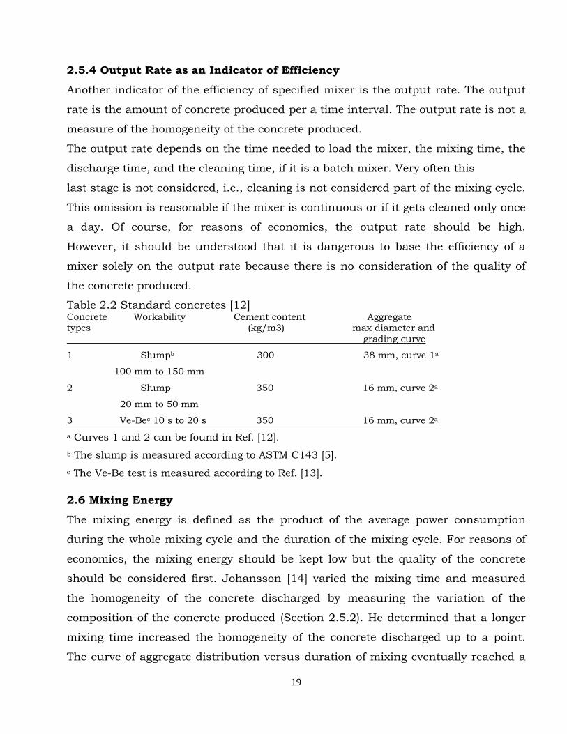
2.5.4 Output Rate as an Indicator of Efficiency
Another indicator of the efficiency of specified mixer is the output rate. The output
rate is the amount of concrete produced per a time interval. The output rate is not a
measure of the homogeneity of the concrete produced.
The output rate depends on the time needed to load the mixer, the mixing time, the
discharge time, and the cleaning time, if it is a batch mixer. Very often this
last stage is not considered, i.e., cleaning is not considered part of the mixing cycle.
This omission is reasonable if the mixer is continuous or if it gets cleaned only once
a day. Of course, for reasons of economics, the output rate should be high.
However, it should be understood that it is dangerous to base the efficiency of a
mixer solely on the output rate because there is no consideration of the quality of
the concrete produced.
Table 2.2 Standard concretes [12] Concrete Workability Cement content Aggregate types (kg/m3) max diameter and grading curve
1 Slumpb 300 38 mm, curve 1a
100 mm to 150 mm
2 Slump 350 16 mm, curve 2a
20 mm to 50 mm
3 Ve-Bec 10 s to 20 s 350 16 mm, curve 2a
a Curves 1 and 2 can be found in Ref. [12].
b The slump is measured according to ASTM C143 [5].
c The Ve-Be test is measured according to Ref. [13].
2.6 Mixing Energy
The mixing energy is defined as the product of the average power consumption
during the whole mixing cycle and the duration of the mixing cycle. For reasons of
economics, the mixing energy should be kept low but the quality of the concrete
should be considered first. Johansson [14] varied the mixing time and measured
the homogeneity of the concrete discharged by measuring the variation of the
composition of the concrete produced (Section 2.5.2). He determined that a longer
mixing time increased the homogeneity of the concrete discharged up to a point.
The curve of aggregate distribution versus duration of mixing eventually reached a

20
plateau, implying that any further mixing would not improve the homogeneity of the
concrete produced. According to the measurements performed by Johansson [14],
the time at which the plateau is reached depended strongly on the type of mixer
and has some dependence on the maximum coarse aggregate size. Of course,
shorter mixing times that still obtain an acceptable homogeneity for a given mixture
are desired. This could determine the best mixer for the application, if the loading
method is kept constant. Therefore, the optimum mixing time should be determined
for each concrete mixture before starting a large production. The power
consumption is often used to estimate the workability of the concrete. The theory
behind this usage is based on principles of operation of a rheometer. A rheometer is
an instrument that measures the stress generated by the material tested while
applying a strain. In this case the strain is the constant speed of the blades and the
stress is measured by the energy consumption. If it were possible to rotate the
blades at different speeds and measure the power consumption at each speed, the
mixer could be used to characterize the concrete’s rheological behavior.
Nevertheless, while the data obtained will not allow calculation of the rheological
parameters of the concrete in fundamental units because the flow of concrete in a
mixer is not linear and no equations are available for such a case, the measure of
the energy consumption at one speed can be used to compare concretes prepared
with the same mixer [15], or to monitor the workability of a concrete while it is
mixed. For a given mixture composition, if the power consumption increases, it is
an indication that the concrete workability is reduced. Therefore, the operator could
determine the necessity of adding more water or HRWRA to obtain the workability
desired. This methodology will avoid the necessity of discharging the mixer,
measuring the workability using for instance a slump cone just to determine the
amount of water, or determining the HRWRA dosage needed to obtain the desired
workability.
Therefore, the mixing energy is a very useful tool to determine variation in the
workability of the concrete being produced. However, there is no strong evidence
that mixing energy can be used to determine the efficiency of a mixer, unless the
only performance requirement is the workability.

21
2.7 Wear and Tear
In determining mixer efficiency, the main focus has been determining the
homogeneity and the quality of the concrete produced. It was assumed that the
mixer was operating as designed by its manufacturer. But long usage of a mixer
leads to wear of the blades and/or scraper, or the build-up of materials (hardened
mortar or cement paste) on the blades, the container, and/or the scraper. Wear and
build-up will change the geometry of the mixer and therefore the flow pattern of the
concrete, and may lead to changes in the concrete produced [16]. To avoid this
situation, the concrete mixer should be thoroughly cleaned at the end of each day of
operation and the blades and/or scraper changed on a regular schedule.
It can be argued that criteria for a mixer selection should include
• ease of cleaning;
• cost and difficulty of replacing the blades or parts;
• sensitivity of the mixer to wear and tear of the blades.
Therefore, to summarize what is stated in the literature, the existing concrete mixer
machines have some short comings in the following areas.
Micro enterprises and TVET institution are not engaged in producing concrete
mixing machine.
Portable concrete mixers may be powered by a gasoline engine, although it is
more common that they are powered by electric motors using standard
mains current and if there is interruption of electric power, the operation
become stopped.
The older mixers are heavy and cannot be moved as easily. They are still self
powered with an electric motor.
But our design is based on the consideration of avoiding as much all the
above mentioned problems. So that, the above literatures we organized are helpful
in finding the science of production of concrete mixing machine.

22
CHAPTER THREE
MATERIALS AND METHODOLOGY
3.1 Introduction
This chapter presents the research methodology employed to achieve the thesis
objective including instrument development, sample selection, data collection and
data analysis.
3.2 Instrument development
In this study, exploratory research method is used to identify key issues and key
variables. Exploratory research might involve a literature search or conducting
focus group interviews. The exploration of new phenomena can help our need for
better understanding and test the feasibility of a more extensive study, or determine
the best methods to be used in a subsequent study. For these reasons, exploratory
research is broad in focus and provides definite answers to specific research issues.
3.3 Sample selection
Sampling involves selecting relatively small number of elements from the large
defined group of elements and expecting that the information gathered from small
group allow generalization to be made about the larger group of population.
(Research method for construction 3rd edition)
The sampling units are the defined target population elements available for
selection during the sampling process. In this research, three of Adama Town
construction site workers are selected purposely as the total population from
Afrotsion construction PLC, Tekleberhan Ambaye construction PLC, and Small and
Micro enterprise construction site contractors since the result can be considered for
the whole building construction site workers in the country.
A total of 15(5 from SME, 3 from Tekleberhan Ambaye and 7 from Afrotsion)
numbers of concrete mixing workers are randomly selected from the population of
30 from the three sites. The reason why only Adama Town is selected for this study
is, the town is near to Adama Science and Technology University(ASTU) and due to
limited budget and time constraint as well; the researchers couldn’t include other
places from the country. The sampling is selected by using random sampling
23
method. The sample ratio can give sufficient information because it is taken 50%
out of total population.
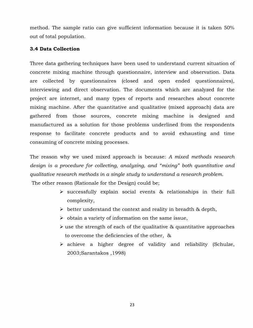
3.4 Data Collection
Three data gathering techniques have been used to understand current situation of
concrete mixing machine through questionnaire, interview and observation. Data
are collected by questionnaires (closed and open ended questionnaires),
interviewing and direct observation. The documents which are analyzed for the
project are internet, and many types of reports and researches about concrete
mixing machine. After the quantitative and qualitative (mixed approach) data are
gathered from those sources, concrete mixing machine is designed and
manufactured as a solution for those problems underlined from the respondents
response to facilitate concrete products and to avoid exhausting and time
consuming of concrete mixing processes.
The reason why we used mixed approach is because: A mixed methods research
design is a procedure for collecting, analyzing, and “mixing” both quantitative and
qualitative research methods in a single study to understand a research problem.
The other reason (Rationale for the Design) could be;
successfully explain social events & relationships in their full
complexity,
better understand the context and reality in breadth & depth,
obtain a variety of information on the same issue,
use the strength of each of the qualitative & quantitative approaches
to overcome the deficiencies of the other, &
achieve a higher degree of validity and reliability (Schulze,
2003;Sarantakos ,1998)

24
3. 4.1 Survey questionnaire
Survey questionnaire is designed and distributed for assessing concrete mixing
machine in selected areas. Twelve questionnaires were distributed and collected all
in all from the randomly selected users. The composition of the persons who were
participated in the response of the questionnaire includes:
Concrete mixing workers, concrete users, technical workers, and others who work
in related area.
The objectives of the questionnaire are:
- To identify the problems related with concrete production for building and
construction workers.
- To assess attitudes and tendency towards concrete mixing machine
- To know how effectively is the concrete mixing machine is used in the
construction site.
- To compare the existing mixing operation with two ways (electrical and manual)
concrete mixing machine.
The survey questionnaire contains about fifteen questions requiring two types of
answers.
a. The first type uses options from the alternatives (objective)
b. Subjective type questions, which need brief answer.
3.4.2 Interview
The interview included from different private sectors and customers specially small
and micro enterprise. Structured interviews (face to face) were conducted with
different concrete mixing workers and concrete product users. Most of the interview
questions conducted is similar to the questions in the questionnaire. This helped us
to crosscheck the response given by the respondents on both methods of
assessment.
Objectives of conducting the interviews:
- To investigate feeling of the people who use the existing concrete mixing
machine in Adama town.
- To observe overall activities and processes in the respective areas of concrete
25
producers for construction.
- To assess the existing system of concrete mixing method and identify the
drawbacks.
- To assess the need of users and gathering data that are related with how to
make some changes to the existing concrete mixing system.
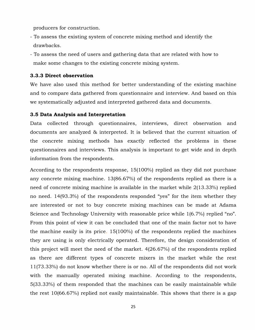
3.3.3 Direct observation
We have also used this method for better understanding of the existing machine
and to compare data gathered from questionnaire and interview. And based on this
we systematically adjusted and interpreted gathered data and documents.
3.5 Data Analysis and Interpretation
Data collected through questionnaires, interviews, direct observation and
documents are analyzed & interpreted. It is believed that the current situation of
the concrete mixing methods has exactly reflected the problems in these
questionnaires and interviews. This analysis is important to get wide and in depth
information from the respondents.
According to the respondents response, 15(100%) replied as they did not purchase
any concrete mixing machine. 13(86.67%) of the respondents replied as there is a
need of concrete mixing machine is available in the market while 2(13.33%) replied
no need. 14(93.3%) of the respondents responded “yes” for the item whether they
are interested or not to buy concrete mixing machines can be made at Adama
Science and Technology University with reasonable price while 1(6.7%) replied “no”.
From this point of view it can be concluded that one of the main factor not to have
the machine easily is its price. 15(100%) of the respondents replied the machines
they are using is only electrically operated. Therefore, the design consideration of
this project will meet the need of the market. 4(26.67%) of the respondents replied
as there are different types of concrete mixers in the market while the rest
11(73.33%) do not know whether there is or no. All of the respondents did not work
with the manually operated mixing machine. According to the respondents,
5(33.33%) of them responded that the machines can be easily maintainable while
the rest 10(66.67%) replied not easily maintainable. This shows that there is a gap
26
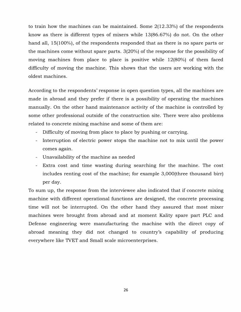
to train how the machines can be maintained. Some 2(12.33%) of the respondents
know as there is different types of mixers while 13(86.67%) do not. On the other
hand all, 15(100%), of the respondents responded that as there is no spare parts or
the machines come without spare parts. 3(20%) of the response for the possibility of
moving machines from place to place is positive while 12(80%) of them faced
difficulty of moving the machine. This shows that the users are working with the
oldest machines.
According to the respondents’ response in open question types, all the machines are
made in abroad and they prefer if there is a possibility of operating the machines
manually. On the other hand maintenance activity of the machine is controlled by
some other professional outside of the construction site. There were also problems
related to concrete mixing machine and some of them are:
- Difficulty of moving from place to place by pushing or carrying.
- Interruption of electric power stops the machine not to mix until the power
comes again.
- Unavailability of the machine as needed
- Extra cost and time wasting during searching for the machine. The cost
includes renting cost of the machine; for example 3,000(three thousand birr)
per day.
To sum up, the response from the interviewee also indicated that if concrete mixing
machine with different operational functions are designed, the concrete processing
time will not be interrupted. On the other hand they assured that most mixer
machines were brought from abroad and at moment Kality spare part PLC and
Defense engineering were manufacturing the machine with the direct copy of
abroad meaning they did not changed to country’s capability of producing
everywhere like TVET and Small scale microenterprises.
27
CHAPTER FOUR
DESIGN ANALYSIS AND MATERIAL SELECTION
4.1 Introduction
This chapter introduces the design analysis and material selection of critical
components for manual and electrical concrete mixing machine on the problems
identified with a view to evaluate the necessary design parameters, strength and
size of materials for consideration in the selection of the various machine parts.
Design
From the study of existing ideas, a new idea has to be conceived. The idea is then
studied keeping in mind its commercial success and given shape and form in the
form of drawings. In the preparation of these drawings, care must be taken of the
availability of resources about money, men and materials required for the
successful completion of the new idea into an actual reality. In designing a machine
component, it is necessary to have a good knowledge of many subjects such as
Mathematics, Engineering Mechanics, Strength of Materials, Theory of Machines,
Workshop Processes and Engineering Drawing.
General Considerations in Design
- Type of load and stresses caused by the load;
- Motion of the parts or kinematics of the machine;
- Selection of materials;
- Form and size of the parts;
- Ergonomic consideration; and
- Use of standard parts and safety operations; etc.
This designs of manual and electrical concrete mixer machine focus on two
functions that are manual mixing and electrical mixing process. Starting from the
idea of design principles and functional requirements, the researchers designed the
parts of the machine based on the design procedures.
Redesigned Machine description
The mixing process is done by the impact of a cylindrical drum equipped with a
number of blade mounted on its sideline attached to the central shaft. Its operation
is achieved by rotational motion of a cylinder fitted with beater peg inside the drum
28
and its stationary grid (twist) which results in the process of shake (stir) the grain
inside the drum during the mixing process of concrete. The mini concrete mixing
machine was redesigned to be made from the following major parts.
I. Mixing blade: is a device that homogeneously mix cement, aggregate such as
sand or gravel, and water to form concrete, by means of a revolving drum. It
is the part where the grains are beaten and remix the component of an
aggregate simultaneously in the barrel to make concrete. It is made from
HSS, that has 2 blades attached with inside of the revolving drum of the
machine with a wing length of 250mm from the central shaft. It consists of a
rotary drum with beater pegs and a stationary concave grid, normally in axial
flow thresher.
II. Mixing drum: It is the standard part made of mild steel material and it is
a t t a che d w i t h a sha f t and u - c hann e l f r om mo t o r side with
external diameter of 580mm and length of 810mm. It is used as a container
to mix aggregate, cement sand and water for the production of concrete. And
also 480mm length u-channel is welded on drum base as reinforcement.
U- Channel is firmly welded to the base of a drum to fix shaft end by bolt
together. The function of this u-channel is to provide strength to the drum
base because drum base cannot alone with-stand the twisting load of the
shaft.
U-channel of 70, 80 and 560mm of internal, external and length respectively
with T- shape are attached with the base of the drum by shielded metal arc
welding.
29
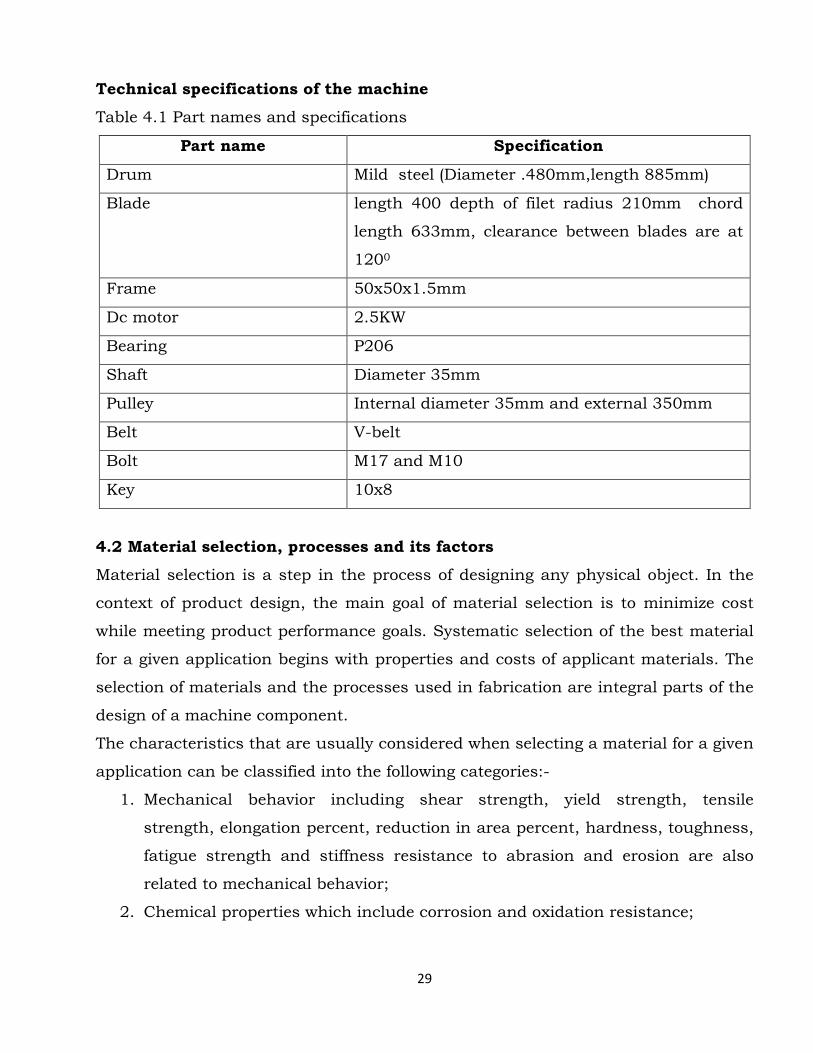
Technical specifications of the machine
Table 4.1 Part names and specifications
Part name Specification
Drum Mild steel (Diameter .480mm,length 885mm)
Blade length 400 depth of filet radius 210mm chord
length 633mm, clearance between blades are at
1200
Frame 50x50x1.5mm
Dc motor 2.5KW
Bearing P206
Shaft Diameter 35mm
Pulley Internal diameter 35mm and external 350mm
Belt V-belt
Bolt M17 and M10
Key 10x8
4.2 Material selection, processes and its factors
Material selection is a step in the process of designing any physical object. In the
context of product design, the main goal of material selection is to minimize cost
while meeting product performance goals. Systematic selection of the best material
for a given application begins with properties and costs of applicant materials. The
selection of materials and the processes used in fabrication are integral parts of the
design of a machine component.
The characteristics that are usually considered when selecting a material for a given
application can be classified into the following categories:-
1. Mechanical behavior including shear strength, yield strength, tensile
strength, elongation percent, reduction in area percent, hardness, toughness,
fatigue strength and stiffness resistance to abrasion and erosion are also
related to mechanical behavior;
2. Chemical properties which include corrosion and oxidation resistance;

30
3. Physical characteristics including electrical, magnetic and thermal properties.
Density is also included in this category;
4. Process ability which includes castability, workability, weldability and
machinability.
In selecting materials for a given application it is useful to classify them according
to the major function they are expected to perform in service.
One of the most difficult problems for the designer is improper materials selection
for engineering purpose. The best material is one which services the desired
objectives of material selection is at the minimum cost and the required purpose
must be followed.
So that, we considered the flowing factors while selecting material.
- Availability of the material in the form and shape desired;
- Total cost of the material including initial and future cost;
- Material properties as they relate to service performance
requirements;
- Suitability of material for working condition in service;
- Substitutability of the materials; and
- The processing of the material into a finished part.
Generally material selection factors are service performance (specifications),
availability, economics (total cost), material properties, manufacturing processes,
formability and join ability and finishing and coatings.
Figure 4.1 Material selection processes for a machine parts [Automation,
31
Production system and Computer Integrated Manufacturing, 2nd edition]
4.2.1 Material selection for significant parts/components
Selecting the right material for the machine can fulfill the functional requirement of
the specific part. We followed the digital logic methods to select the suitable
material.
The steps for digital logic methods are:-
- Set the functional requirements for the part under consideration. This
are used to set rating factor;
- Rank the rating factors (properties) then determine the weight factors;
- Total number of decision/N/= Where n is the number of rating
factors/properties/;
- Write the most suitable candidate materials and enlist properties from
standard data table /the data quantitative or qualitative/ ;
- Normalize the outcomes of the parts;
- Value outcomes and overall satisfaction of parts. The overall satisfaction
shall at last ranked, and the rank shows the result on the basis of the
allocated weight factors which gives the best overall satisfaction for the
functional requirements of the part.
4.2.1.1 Material selection for Shafts
In order to minimize deflections, medium carbon steel is the logical choice for a
shaft material because of its high modulus of elasticity, though cast or nodular iron
is sometimes also used, especially if gear or other attachments are integrally cast
with the shaft. Most machine shafts are made from low-to- medium carbon steel,
either cold rolled or hot rolled, though alloy steels are also used where their higher
strength are needed. Cold-rolled steel is more often used for small-diameter
shaft(less than about 3-inch in diameter) and hot-rolled used for large size.
(Textbook of machine element Shigley 8th ed.)
Functional requirement for Shaft
The main function of shaft is to transmit power. Since the shaft is subjected to high
torque, it may be bent, so the shaft should have properties that to resist bending
moment and torsion.
32
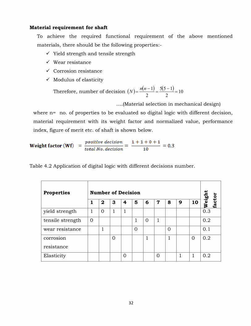
Material requirement for shaft
To achieve the required functional requirement of the above mentioned
materials, there should be the following properties:-
Yield strength and tensile strength
Wear resistance
Corrosion resistance
Modulus of elasticity
Therefore, number of decision 10
2
155
2
1
nnN
….(Material selection in mechanical design)
where n= no. of properties to be evaluated so digital logic with different decision,
material requirement with its weight factor and normalized value, performance
index, figure of merit etc. of shaft is shown below.
Table 4.2 Application of digital logic with different decisions number.
Properties
Number of Decision
Weig
ht
facto
r
1 2 3 4 5 6 7 8 9 10
yield strength 1 0 1 1 0.3
tensile strength 0 1 0 1 0.2
wear resistance 1 0 0 0.1
corrosion
resistance
0 1 1 0 0.2
Elasticity 0 0 1 1 0.2

33
Table 4.3 Applicant material requirements for shaft
No Materials yield
strength
tensile
strength
wear
resistance
corrosion
resistance
modulus of
elasticity
1 AISI NO.1010
hot- rolled
179 324 3 4 12
2 AISI No.1020
hot- rolled
207 379 4 3 12
3 ASTM
No.A570-A
170 310 2 1 13
4 ASTM No.
A675 Grade-
45
155 380 3 2 13
Table 4.4 Normalized value of shaft
No. Material yield
strength
tensile
strength
wear
resistance
corrosion
resistance
modulus of
elasticity
1 SAE/AISI
NO.1010
hot- rolled
86.5 85.3 75 100 92.3
2 SAE/AISI
No.1020 hot-
rolled
100 99.7 100 75 92.3
3 ASTM
No.A570-A
82.13 81.6 50 25 100
4 ASTM No.
A675 Grade-
45
74.9 100 75 50 100

34
Note: - During normalizing numbers 100 is given the maximum number for
higher functional requirement of material and for the remaining number used
in cross multiplication to obtain similar results, but for lower requirements of
material (for example specific gravity) 100 gives to the smallest no. & for the
rest no. use the smaller no. multiplying by 100 divided the no. to obtain the
required result.
Performance index () = (normalized value) (weight factor)
Table 4.5 Shows performance index (value out comes)
From the above result of material selection shows that AISI No.1020 hot
rolled is the material for the shafts so mostly shafts are made of low -to-
medium carbon steel one of these materials is mild-steel.
4.2.1.2 Material selection for large Pulley
Functional requirement for pulley
The main function of pulley is to transmit power from the prime mover to the
driven shaft through belt.
Material requirement for pulley
The material should possess optimal tensile strength;
The material should have adequate value of yield strength;
Density of the material should meet value of safe operation ;
It possesses moderate specific heat capacity;
No. Material Yield strength x 0.3
Tensile strength x 0.2
Wear resistance x 0.1
Corrosion resistance x 0.2
Modulus of elasticity x 0.2
Performance index
Rank
1 SAE/AISI NO.1010 hot- rolled 25.95 17.06 7.5 20 18.46 88.97
2
2 SAE/AISI No.1020 hot- rolled 30 19.94 10 15 18.46 93.4
1
3 ASTM No.A570-A 24.64 16.32 5 5 20 70.96
4
4 ASTM No. A675 Grade-45 22.47 20 7.5 10 20 79.97
3

35
Coefficient of linear expansion of the material should lie at range of
minimal value;
Wear resistance.
Total number of decision/N/ = Where n=5 ; N = = 10
Table 4.6 Weighting factors for pulley
Properties Number of Decision Weight
factor 1 2 3 4 5 6 7 8 9 10
Tensile strength 0 0 1 1 2/10 = 0.2
Yield strength 0 0 0 1 1/10 = 0.1
Density 1 1 1 0 3/10 = 0.3
Specific heat capacity 0 1 0 0 1/10 = 0.1
Coefficient of linear expansion 1 1 1 0 3/10 = 0.3
Table 4.7 Properties of candidate materials for pulley
Materials
Tensile strength
Yield strength
Density
Specific heat capacity
Coefficient of linear expansion
AISI1010 370 300 7.85 0.47 12.20
AISI1035 550 460 7.85 0.48 11.50
ASTM 20 152 152 7.20 0.34 11.00
ASTM 25 197 197 7.35 0.46 10.00
Table 4.8 Normalized outcomes for pulley
Materials
Tensile strength
Yield strength
Density
Specific heat capacity
Coefficient of linear expansion
AISI1010 67 65 100 72 82 AISI1035 100 100 100 71 87 ASTM 20 27 33 92 100 91 ASTM 25 32 39 95 74 100

36
Table 4.9 Shows performance index (value out comes)
Materials
Tensile
strength
x 0.2
Yield
strength
X0.1
Density
x0.3
Specific heat
capacity
x 0.2
Coefficient
of linear
expansion
X 0.3
Performance
Index
R
an
k
AISI1010 13.45 6.5 30 7.2 24.6 81.75 2
AISI1035 20 10 30 7.1 26.1 93.20 1
ASTM 20 5.4 3.3 27.6 10 27.3 73.6 4
ASTM 25 6.4 3.9 28.5 7.4 30 76.2 3
Therefore, from the above candidate materials AISI1035 is a best suitable for
the pulley material which is relatively less weight.
Table 4.10 Application of digital logic with different decisions numbers
No. Properties
Decision number Wf
1 2 3 4 5 6 7 8 9 10 11 12 13 14 15
1 Yield
strength
1 1 0 0 0 0.13
2 Tensile
strength
0 1 0 0 0 0.07
3 Young's
modulus
0 0 1 1 0 0.13
4 Fatigue
strength
1 1 0 1 1 0.27
5 Density 1 1 0 0 0 0.13
6 Corrosion
resistance
1 1 1 0 1 0.27

37
4.2.1.3 Material selection for bearing house
Function requirement
Since the bearing is inserted into the bearing house for supporting the shaft
and facilitate its motion the bearing housing should have a property that resist
the bearing stress and also it resist the torsion of the shaft due to rotational
motion. The machinability of the part should be considered to have a shape of
bearing.
Material Requirement
To satisfy the functional requirement for selecting bearing house, the material
should have:-
- better yield strength-better tensile strength
- higher young's modulus of elasticity-high corrosion resistance
- it should be tough enough-it should be machine able
- it should be light in weight
4.2.1.4 Material selection for bearing
Functional requirement
A bearing is a machine element which supports other moving machine
components (known as Journal, i.e., the portion of the shaft resting on the
sleeve). It permits a relative and smooth motion between the contact surfaces of
the members, while carrying the load.
Since there is a relative motion between the bearing and the moving element, a
certain amount of power must be absorbed in overcoming friction, and if the
surface actually touches, there will be a rapid wear.
Material Requirement
The various considerations in the selection of bearings to satisfy the functional
requirement, the bearing should have:
Direction of load relative to bearing axis;

38
Intensity of loads. Ball bearings can sustain considerable
loads;
Speed of rotation;
Thermal stability;
Shaft stiffness. Rigid bearings are used for stiff well designed
shafts;
Class of accuracy of the machine.
Table 4.11 Shows bearing standards (fundamentals of machine component
design)
Already, we have designed shaft diameter of 35mm. therefore based on the
diameter of shaft and the properties of bearing mentioned above, ball bearing
with Bearing Basic Number L06, from the above table is selected for this
project.
4.3 Design of Critical Components
The main parts of our project includes Motor, Pulleys, shaft, mixing blade, Key,
Bolt, drum and stand etc.
Design of Shaft
The torsion equation may now be written as
= or T = d3 d= we modified the
shaft diameters to 25-38 that is recommended from standard table (text book
of machine design)
The length
ѳ=TL/JG …………………………………. Eq(1)
Bearing Basic
Number
Bore(mm) OD
(mm)
W(mm)
L05 25 47 12
205 25 52 15
305 25 62 17
L06 30 55 13

39
Where T= twisting moment of shaft
L= length of shaft
J= polar momentum of shaft material
G= 0.8x10⁵ mpa
A B C D
50mm 30mm 20mm
T1 390mm T2
Figure 4.1 shaft Assembly with pulley & bearing
J= d4 …………………………………..eq(2)
J= 304 =79481.25mpa
ɵ 0.01 L= 240mm
Therefore the shaft length adopted from the standard table 200 -450mm is
advisable from the standard table machine design page 443
4.3.1 Design of Driver Shaft
This shaft is a rotating solid part which is used to transmit power from the
electric motor through belt and pulleys to the driven shaft through pulley by
means of key. The power is delivered to the shaft by some tangential force and
the resultant torque (or twisting moment) set up wit in the shaft permits the
power to be transmitted to the driven shaft. The required torque to transmit
power to the driver shaft is obtained by using the following relation.

40
We know that power transmitted (in watts) by the shaft,
P = , ω= so, T = Where T- is twisting moment in N-m
n - is speed of shaft in RPM = 1400 RPM
P-is power required = 2.5 Kw = 17183.8 N-m
d
dT
2
3
…………………………….eq(3)
14002
6010005.2
x
wxxT
Where
d=diameter of the shaft T= is torque transmitted by shaft
Sys =yield stress of shaft 400 c8 taken from machine design table below Fs = factor of safety
The members like pulleys, bearing house, mounted on the shaft are exerted
forces which cause the shaft to bending and twisting.
The material to be selected for the manufacturing of shaft for the project
should meet the following criteria. The desirable properties of the materials for
the designed shaft should be;
- Sufficient in strength-Machine able
- Impact resistance- Tough and resist fatigue
- Heat resistance
- Good heat treatment
- Wear resistance
Mechanical properties of steels used for shafts (Text book of Machine
design)

41
Table 4.12 Mechanical properties of steels used for shafts
Indian
Standard
Designation
Ultimate tensile
strength in
MPa
Yield
strength in
MPa
Remark
40C8 560-670 200-380 Used for shafts, gears stud bolts,
spindle, washer etc. for light
stressed
45C8 610-700 220-350 Used for lead screws, feed rods
bigger gears, bigger shafted…
50C4 640-760 370
5012 700 minimum 390
From this mechanical properties of steels used for shafts, we choose 40C8
material because our project is derived with simple mechanism by considering
its yield strength of 380 MPa.
Because the ordinary transmission shaft are made of medium carbon steel with
a carbon content from 0.15 % to 0.40% such as 30 C8 or 40 C8 these steel are
commonly called machinery steel where the greater strength is required high
carbon steel such as 45C8 or 50C8 are employed.
Stresses on the shafts
The stresses induced in the shaft are:
- Shear stress due to transmission of torque (i.e. due to torsional load)
- Bending stress (compression) due to forces acting up on the shaft
- Stress due to combined torsional and bending loads.
Maximum permissible working stress for transmission shafts
According ASME code for commercial steel shafts, the maximum permissible
shear stress is taken as 40-42 MPa for shafts with key and 55-56 MPa for
shafts without key.
For shafts purchased under definite physical specification, the permissible
shear stress (allowable shear stress) is 25 % of yield strength but not over 18%
of ultimate strength in tension for shafts with key ways.

42
τ=0.75σy or τ=0.18σu Where τ - is permissible shear stress
σy -is yield strength
σu -is ultimate tensile strength
For this design the permissible stress is τ=0.5σy = 0.5x380 MPa = 190 MPa
τ=0.75σy because it is keyway on the shaft so shear stress is maximum
τmax = 0.75σy = 0.75x380mpa =285mpa
In designing shafts on the bases of strength, the following cases may be
considered.
i. Shafts subjected to twisting moment or torque only
When the shaft is subjected to twisting moment (torque) only, then the
diameter of the shaft may be obtained by using the torsion equation.
= Where, T- is twisting moment acting up on the shaft
J- is polar moment of inertia of the shaft about the axis of rotation
τ - is torsional shear stress and r- is radius of the shaft = d/2
For round solid shafts polar moment of inertia,
J = d4…….. ………………………….eq(4)
The torsion equation may now be written as
d= ……. ………………………….. eq(5)
= or T = d3
P = , = =
p
150mm 150mm
Ra Rb
Figure 4.2 Twisting moment or torque of shaft

43
The tangential force due to the torque of pulley becomes
Ft
Shear force and bending moment
X X
Z
YRayy YRby
Figure 4.3 Shear force diagram for shaft
Radial force (Fr) in400 grooving of the pulley is
Fr= Fttan =343.68Nmm xtan400 =288.838Nmm
Reaction force at the bearing point
Ray=
Rax =
Therefore reaction force Ra and Rb becomes
2
2
2
2
19.144
84.171
Rby
RaxRbRa =224.32
Resultant force (F) is
W = Ft = =448.64N
The shear load and bending moment acting on the shaft can be
obtained as
B.M at Z=0
VX= Rax =
B.M at Z=200mm
VX= Rax –Fr

44
VX =144.19-288.38 =-144.19N
B.M at Z=300mm
VX= Rax –Fr +Rbx
VX =144.19-288.38+144.19 =0
Vx= 144.19N
100mm
A B
200mm
Vx = -144.19N
Figure 4.4 Bending moment acting on the shaft
Reaction force @ zy plane
B,M at Z = 0
B.M @ Vy =Ray= = =
Vy = 56.84 N
B.M @ y =200mm
Vy =Rby – Ft
Vy = 56.84 - 113.68
Vy =- -56.84 N
B.m@ Z=300mm
Vy = Ray –Ft+Rby
Vy = 56.84 -113.68 +56.84 Vy = 0
Va =56.86N 100mm
A B
200mm Vb = -56.86N
Figure 4.5 Bending moment acting on the shaft @ xz plane

45
shear force of magnitude XZ plane
X
Z
300mm
Figure 4.6 Shear force of magnitude XZ plane
The bending moment of @ xy plane is
B.m @z =0
Mx =Rax(Z-0) =Rx(0-0)
B.m @ z = 200mm
Mx = Rax(200-0)-Fr(0-0)
Mx =28838N
B.M @z= 300
Mx = Rax(200-0)-Fr(z-200mm) +Rax(z-300)
Mx =144.19(300-0) -288.38(300-200) +144.19(300-300)=0
B.m @Z =275mm
Mx = Rax (Z-0) –Fr(Z-65mm)
Mx = 144.19(275mm)-288.38(275.38-200)
Mx =39625.25- 21628.5
Mx =18023.75N.mm
38730N
34368N
A B C
275mm
300mm
Figure 4.7 Magnitude of bending moment @ yz plane

46
Bending Moment of YZ Plane
B.M @ Z= 0
My =Ray(Z-0)
B.M @ Z=200mm
My = Ray (Z-0) Ft(Z-0)
My= 171.84(200-0) -343.68(200-200)
My = 34368N.mm
B.M @Z =300mm
My =Ray(Z-0)- Ft(Z-200) +Rby(z-300mm)=0
B.m @ z=275mm
My = Ray (z-0)- Ft(Z-200)
My = 171.84(275-0) -113.68(275-200)
My= 47256-1136.75
My =38734N.mm
Magnitude of bending moment
M 2 =Mx2 +My2 ………………………...eq(6)
= 288382 + 343682
=44864.1245N.mm
Magnitude of at Z =275mm
B.M @ Z=275mm
M= 2222 3436875.18023 MYMX = 34416.35 N.
44864.1245N.mm
34416.35Nmmm
A B
275mm
300mm
Figure 4.8 Magnitude of bending moment

47
Design of shear stress of shaft
The torsion equation may now be written as
= or T = d3
T = d3 170609.45= = 20.28N.mm = ڄ353
So 54.34mpa>20.28 mpa The design is safe
Deflection of shaft
Since the shaft is considered as simple beam concentrated load (P) a center
X P
L/2 L/2
L
Figure 4.9 Deflection of the shaft
Y max = where Ymax = maximum shear stress of the shaft
P= load of the shaft
E = the elongation of the shaft for steel is 209.55x10²mpa
I = momentum of inertia the solid shaft
L = length of the shaft
I =πd4 / 64 ---------------------------eq(7)
I = π354 / 64 =736244.4N.mm
Max =44864.1245N.mm
So Y max = = =0.0283x106 mm
Yx (when x<L/2) =
Since L/2 =300/2 =150mm
Let take X= 150/2 45 mm
Y max = {(419.67x150)(3x(3002 -4(1502)}
Y max= 0.01133mm

48
The transition shaft
Shafts subjected to combined twisting moment(T) and bending
moment(M)
When the shaft is subjected to combined twisting moment and bending
moment, the shaft must be designed on the bases of the two moments
simultaneously. Two types of theories have been subjected to account for
the elastic failure of the shaft when it is subjected two various combined
stresses. The two types of theories are:
a. Maximum shear stress theories: used for this design because it is used
for ductile materials such as mild steel
b. Maximum normal stress theory: used for brittle material such as Cast
iron.
According to Maximum shear stress theory, the maximum shear stress in
the shaft is given by
Substituting the values of τ and σb from torsion equation and bending
equation, we have
max= 2
max = max d3………………………..eq(8)
The expression 2 is known as equivalent twisting moment and is
denoted by Te.
The equivalent twisting moment Te may be defined as the twisting moment,
which when acting alone produces the same shear stress ( ) as the actual
twisting moment. By limiting the maximum shear stress ( max) equals to the
allowable shear stress ( ) for the shaft material equation4.8 can be written
as:
Te = d3………..……………………eq(9)

49
I. Maximum principle stress. Since the shaft is subjected to bending and
torsion moment at any axial force.
x =b = ……………………....eq(9a)
bm = ………………. …….……………eq(9b)
By substituting the equation
bm1 = ……… ..eq(10)
Ft =
Maximum bending of on the pulley for shaft
Mb =
1 =
1 =
1 =
1 =
1 =
Therefore Design is safe because 54.34N.mm>35.65N.mm
Experimental investigation suggest that maximum principle stress theory
gives good prediction for brittle material that are made up of ductile
material, like steel and therefore it is not applicable to shaft design.
II. maximum shear stress is theory is the principal shear stress
max = …………..……eq 11
max=
max =the lower of the two values is and there are key ways on the shaft
must be Tmax=0.75x54.34N .mm2 =37.5N.mm
So, the design is safe 37.5N.mm>28.3N.mm
III. Equivalent torsional moment of the expression called

50
Te = =
IV. Equivalent torsional moment
Tb =
Teb=
ASME code shaft design Value of shock and fatigue factor kb and kt
Where kb=fatigue factor
Kt=shock factor
Table 4.13 ASME code for shaft design Value of shock and fatigue factor
Application Kb kt
1 Load gradually applied 1.5 1.0
2 Load suddenly applied (minor shock) 1.5-2.0 1.0-1.5
3 Load suddenly applied (heavy shock) 2.00-3.00 1.5-3.0
max = ………eq 12
max = =42.5N.mm
Therefore the design are safe because 54.34n/mm2>42.5N.mm2
1 =
=
=
= 53.43N.mm
Also the design is safe because 54.34mpa >53.43mpa
4.3.1 Design of pulley
Pulleys are used to transmit power from one shaft to another by means
of belts. Since the velocity ratio is the inverse ratio of the diameters of
driving and driven pulleys, therefore the pulley diameters should be
carefully selected in order to have a desired velocity ratio. The pulleys
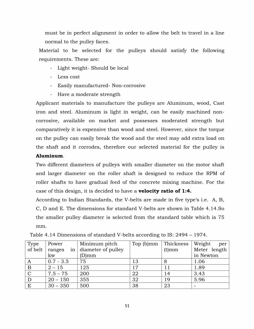
51
must be in perfect alignment in order to allow the belt to travel in a line
normal to the pulley faces.
Material to be selected for the pulleys should satisfy the following
requirements. These are:
- Light weight- Should be local
- Less cost
- Easily manufactured- Non-corrosive
- Have a moderate strength
Applicant materials to manufacture the pulleys are Aluminum, wood, Cast
iron and steel. Aluminum is light in weight, can be easily machined non-
corrosive, available on market and possesses moderated strength but
comparatively it is expensive than wood and steel. However, since the torque
on the pulley can easily break the wood and the steel may add extra load on
the shaft and it corrodes, therefore our selected material for the pulley is
Aluminum.
Two different diameters of pulleys with smaller diameter on the motor shaft
and larger diameter on the roller shaft is designed to reduce the RPM of
roller shafts to have gradual feed of the concrete mixing machine. For the
case of this design, it is decided to have a velocity ratio of 1:4.
According to Indian Standards, the V-belts are made in five type’s i.e. A, B,
C, D and E. The dimensions for standard V-belts are shown in Table 4.14.So
the smaller pulley diameter is selected from the standard table which is 75
mm.
Table 4.14 Dimensions of standard V-belts according to IS: 2494 – 1974.
Type of belt
Power ranges in kw
Minimum pitch diameter of pulley (D)mm
Top (b)mm Thickness (t)mm
Weight per Meter length in Newton
A 0.7 - 3.5 75 13 8 1.06 B 2 – 15 125 17 11 1.89 C 7.5 – 75 200 22 14 3.43 D 20 – 150 355 32 19 5.96 E 30 – 350 500 38 23 -

52
Now from the selected small diameter of pulley and velocity ratio (VR), it can
calculate the large pulley diameter on the roller shaft.
Now from the selected small diameter of pulley and velocity ratio (VR), it can
calculate the large pulley diameter on the roller shaft.
VR = ……………………….………. Eq(13)
= Where d – is diameter of small pulley on the motor shaft;
D – is diameter of larger pulley on the drive shaft;
the large diameter adopted 250mm- 500mm is recommendable from standard
table in machine design book table 17 page 455.
Now by taking 1400 RPM of motor (on smaller pulley), the RPM of the larger
pulley (on the driven shaft) is given by dxn1 = Dxn2 where n1 –is RPM of
smaller pulley. N2- is rpm of larger pulley
n2/d =n1/D n2 = n1xd/D n2 = 1400rpmx75 mm/300mm = 350rpm
n2 =350rpm
let as now the pulley speed 25m/sec
V = 25m/secx75mm/300mm= 6.25m/sec
So the design is safe 25m/sec >6,25m/sec
Force analysis of small pulley
We know that power transmitted (in watts) by the shaft,
P = , ω= so, T = Where T- is twisting moment in N-m
n - is speed of shaft in RPM = 1400 RPM
P-is power required =2.5wat
T = = 17052.315 N-m
Free body diagram of the force and moment acting on small pulley train
Ft
Ra
Figure 4.10 Free body diagram of force analysis on the pulley

53
Tangential force (Ft)
Ft=Dp
Tp2………………………………..eq(14)
Ft= Tangential force
Tp= torque transmitted by pulley
Dp= diameter of small pulley
Ft)
FR=Fttan(ɵ)………………..………….eq(15)
@ Radial force(Fr) =Pr =FR=Fttan(ɵ)
(Fr) =1136.8x tan400 =953.9N
cos
)(Ft
Fr …………………………….eq(16)
Resultant force cos
)(Ft
Fr
(Fr) =1483.99
Pulley bending
@reliability of material (R) =0.95
@No. of load cycle (N)= 109
K=1
@ and design factor =2.5
V=
Dynamic factor of shaft (KV) =
A= 56+56(1-B)
B= 0.25(12-QV) Where QV= 0.8255 it comes from machine design Norton
A =56+56(1-0.8255) =59.77
Whereas KV =59.77+779.21(0.5)0.825
Then bending stress on small pulley
= =5895.127psi

54
4.3.3 Determination of Belt Length.
For any type of the belt drive it is always desirable to know the length of
belt required. It will be required in the selection of the belt. The length
can be determined by the geometric considerations. However, actual
length is slightly shorter than the theoretically determined value.
Figure 4.11 Belt drives(From Engineering Data book for v – belt.)
The belt drive is shown in Figure 4.1. Let O1 and O2 be the pulley centers
and AB and CD be the common tangents on the circles representing the
two pulleys.
The total length of the belt ‘L’ is given by
L = AB +Arc BH + DC+ Arc CGA, equals to the formula;
L = 2C + 1.57(D+ d) +((D - d)2 ) / 4C
Where, C= center distance, D = driven pulley (larger pulley), d = driver
pulley (smaller pulley)
Let r be the radius of the smaller pulley, R = the radius of the larger
pulley,
C be the center distance between the pulleys which is 400 mm based on
the design, and β be the angle subtended by the tangents AB and CD
with O1O2.
By geometry, < O2O1N = < C O1 J = < DO2K = β
Arc BHD = ( + 2 β) R, and Arc CGA = ( + 2 β)r
AB = CD = O1N = O1 O2Cos β = C cos β
Sin β = (D - d)/C = (300-75)/400 = 0.5625
β = Sin-1(0.5625) = 34.230
L = 2C + 1.57(D+ d) + (D - d)2 / 4C

55
L = 2(400) + 1.57(300 + 75) +
= 800 + 588.75 + 31.64
= 1420.39 mm
From standard table, SPZ it is close to the datum length = 1420mm and
inside diameter, Li = 1400 mm.
Therefore, belt specification for this machine is ZX 55 x 1400 Li and
1420 L is selected based on the following table. These data are suitable
and ISO standard because it describes the relations of center distance,
pulley diameters and belt dimensions. In addition, it guides to select
standard sizes and appropriate movements.
Table 4.15 Torque f l e x ® v- belt s (ISO standard of Good year’s Belt
products)
Belt reference Imperial reference (inch)
Inside length Li (mm)
Datum length Ld (mm)
ZX 53 ½ 53 ½ 1365 1385 ZX 53 ½ 53 ½ 1365 1385 ZX 54 54 1375 1395 ZX 54 ½ 54 ½ 1390 1410 ZX 55 55 1400 1420 ZX 56 56 1425 1450 ZX 57 57 1450 1470 ZX 57 ½ 57 ½ 1465 1485 ZX 58 ¼ 58 ¼ 1475 1500 ZX 58 ½ 58 ½ 1490 1510
Contact Angle of belt and pulley
These angles are important because commercially available belts rated with
on assumed contact angle of 1800. This will occur only if the drive ratio is
1:1(no speed change). The angle of contact on the smaller of the two pulley
will always less than 1800, requiring a lower power rating. The tensile force
in the belt maximum on the tight side of the belt. The bending of the belt
around the pulley, maximum at the tight side of the belt bends around the
smaller pulley. Where, 1 = Contact angle of belt on small pulley.
2 = Contact angle of belt on large pulley.
L = Belt length.
C = Center distance between pulleys
d = Small pulley diameter.

56
<AGC = 1 = 1800 – 2sin-1[ ]
< BHD = 2 = 1800 + 2sin-1[ ]
Contact angle of small pulley (1) Contact angle of large pulley (2)
1 = 180 – 2sin-1[ ] 2 = 180 + 2Sin-1[ ]
= 180 – 2Sin-1[ ] = 180 + 2Sin-1[ ]
= 180 – 2Sin-1[ ] = 180 + 2Sin-1[ ]
1 = 147.330 2 = 212.670
Tensions of belt
P = (T1-T2) V
Where, T1- is tension on the tight side of belt
T2 - is tension on the slack side of belt
V- is velocity of the belt in small pulley
P -is power from the above design =2,5x10³ watt
That is V= = = 5495 m/s
Therefore, T1-T2 = P/V =
Figure 4.12 Belt tension
T1-T2 = 0.645N ………………….eq(17)
2.3 log ( ) = µ where, µ- is coefficient of friction between the smaller
pulley and v-belt by taking µ= 0.12 from table µ - is contact angle on small
pulley in radian that is 147.33o = 2.57 rad
2.3 log ( ) = 0.12x2.57
log ( ) = = 0.134
= 1.36 by taking anti log of 0.134
T1=1.36T2…………………………eq(18)

57
Therefore by combining the two equations, that is:
1.36T2 - T2=0.645N T2 = = 1.8Nin the slack side
T1=1.36T2 = 1.36x 1. T1=2.45N in the tight side
Square sunk key: the only difference between a rectangular sunk key and a
square sunk key is that its width and thickness are equal, i.e w=t=d/4
There two failure mecanism of key :-
1. When it can be sheared during stress (Torsional shear stress in the key)
2. When it can be crushed due to the comprehensive bearing force
Figure 4.13 Force acting on the key
Let T=Torque transmitted by the shaft
F=Tangential force acting at the circumference of the of the shaft
D=Diameter of the shaft
L=length of the key
W=width of the key
T=thickness of the key, and
cand =Shear and crushing stresses for the material of key
Shear force F = Area of resisting shear x shear stress
F = L x w x ………….4.12
T= F x d/2, T = L x w x x d/17060.198 mpa = Lx10x40 N/mm2 x30/2
L = 17060.198/10x8x40
L= 5.33mm

58
1. Torsional shear stress in the key
let =shear stress on the shaft
T = torque transmitted by the shaft
r= radius of the shaft
J = polar momentum of the solid shaft
=221596.88mpax15mm / 79481.21 =42.5mpa
2. When it can be crushed due to the comprehensive bearing force
Shear force F = Area of resisting crushing x crushing stress
F = L x t/2 x σc ………………………eq(19)
We know that T= F x d/2
T = L x t/2x σc x d/2 ……………….eq(20)
17060.198 N-mm = Lx4x70 N/mm2 x30/2
L = 17060.198/15x4x70 = 40.62 mm
Taking the larger of the two values, developers have length of key.
L = 40.62 mm say 40.62 mm.
So the design is safe 54.45mpa >42.5mpa because the shear stress of
key is less than the permissible value
According to H.F moore the shear strength factor
e = 1-0.2(w/d) -1.1(h/d) ……….eq(21)
Where e =effect of factor the keyway
w = width of the keyway
d = diameter of the shaft
h = height of the keyway
e = 1-0.2(w/d) -1.1(h/d) = 1-0.2(7.5/30) -1.1(5/2x30)
e =0.8125
Therefore, strength of the shaft with
keyway =π/ 16x xd3xe =π/16x40mpax303x0.8125 =17466.162 N
and strength the of the key = L x w x x d/2
= 40.33x10x40mpax30/2
= 241980N

59
39.116.17466
241980
N
N
haftngthofthesNormalstre
ygthofthekeShearstren
So the key is in good design condition
From the design of pulley, the tangential force Ft applied to the rotating the belt
by on the pulley 448.68N. This force acts perpendicular to the face of the pulley
groove that is resulting in shearing of bolts along their axis. This force is
equally distributed through the four bolts. Therefore the force applied in each
bolt is half of the tangential force i.e Fb = 0.5Ft = 0.5x448.68N= 224.34N
Using maximum shear stress theory,
τmax<0.75σy/n ……………………..eq(22)
Because the shaft is keyways
Where τmax-is the maximum shear stress
y - is yield strength of bolt and
n –is factor of safety, by taking n = 5
The bolt has high yield strength which low or medium carbon steel
(Property class 5.8) having yield strength of σy = 520Mpa from data books.
τ = 0.75x520/5 = 78N/mm2
Thus τ= F b/A Where Fb– is force applied on bolt = 224.34N
A –is stress area on bolt = Πd2/4, d is diameter of bolt
T=π ………………………….…. Eq (23)
where d = for the shaft
Shear stress of the bolt
T = 170609.451mpa x4 = 682437.804mpa
682437.80mpa =π = 128.79mpa
Let d1 = Nominal diameter of bolt since the diameter of shaft is 30mm let
as take the number of bolts n=4
And pitch circle diameter of bolt D1= 3d
D1 = 30x3 =90mm

60
Where T= torque transmitted by shaft
d1 = diameter of bolt
= shear stress of the bolt
n= number of bolt it depends on the shaft diameter
D1= pitch circle of diameter of bolts
T = π/4xd12x xnxD1/2 -------------eq(24)
682432.804mpa = π/4x128.79mpa x4x45d2
d =
The coarse tread is the nearest standard size of bolt is M10 is safe take
from the standard table from machine element V.BBHNDARI page 460.
= 2T/πd2D----------------------------eq(25)
= 2x225196.88/3.14x602x 90 = 44.2708 mpa
Since the induced shear stress on the bolt is less than the permissible
shear stress
54.34mpa >44.2708mpa so the design is safe.
Gear ratio
Spur gear ratio
Mg=np = Zp
Np = Zp
= 1400/560 Rpm
= 2.5 &
Mg = Zg/Zp since ZP = 14 minimum number of pinion gear
2.5 = Zg/18 Zg = 45
Spur gear ratio 20 ;560 or 1 ;28
Assume 200 depth involves profile module m =3
M = 1 25.4 = 3 pd = 25.4 = 8.466in(215.05mm)
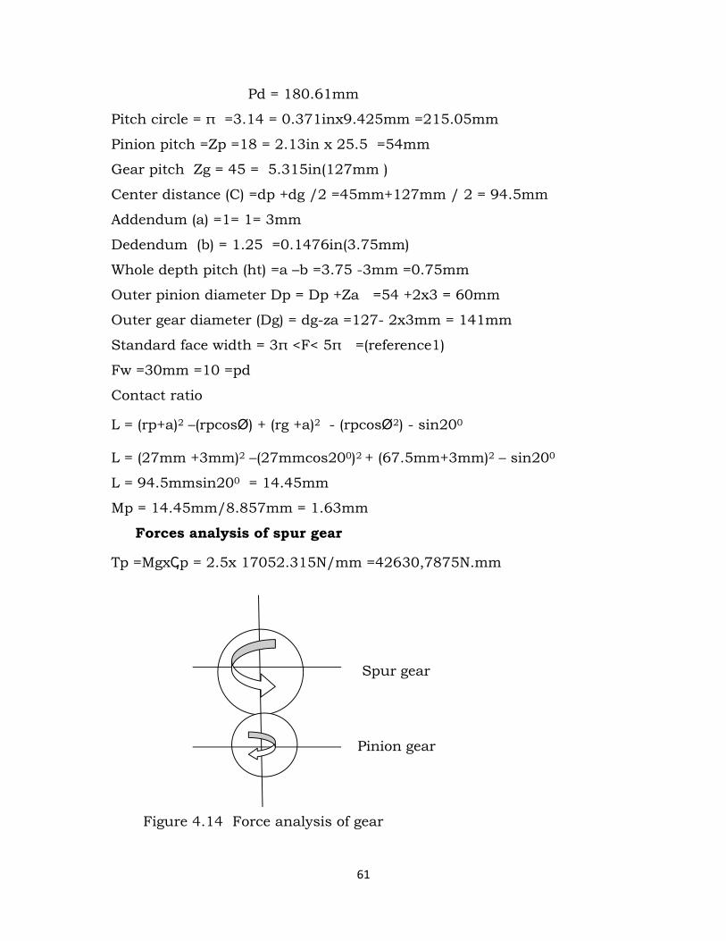
61
Pd = 180.61mm
Pitch circle = π =3.14 = 0.371inx9.425mm =215.05mm
Pinion pitch =Zp =18 = 2.13in x 25.5 =54mm
Gear pitch Zg = 45 = 5.315in(127mm )
Center distance (C) =dp +dg /2 =45mm+127mm / 2 = 94.5mm
Addendum (a) =1= 1= 3mm
Dedendum (b) = 1.25 =0.1476in(3.75mm)
Whole depth pitch (ht) =a –b =3.75 -3mm =0.75mm
Outer pinion diameter Dp = Dp +Za =54 +2x3 = 60mm
Outer gear diameter (Dg) = dg-za =127- 2x3mm = 141mm
Standard face width = 3π <F< 5π =(reference1)
Fw =30mm =10 =pd
Contact ratio
L = (rp+a)2 –(rpcosØ) + (rg +a)2 - (rpcosØ2) - sin200
L = (27mm +3mm)2 –(27mmcos200)2 + (67.5mm+3mm)2 – sin200
L = 94.5mmsin200 = 14.45mm
Mp = 14.45mm/8.857mm = 1.63mm
Forces analysis of spur gear
Tp =MgxႺp = 2.5x 17052.315N/mm =42630,7875N.mm
Spur gear
Pinion gear
Figure 4.14 Force analysis of gear

62
Tangential force = 2xTp/dp = 2x17052.315 N.mm/ 54mm 631.567N
Radial force (fr) = pr =Fr = Ft tanØ = 631.567xtan200 =229.87N
Resultant force = 631.57 / cos200 672.1N
Material selection of gear
Based on the material selection guidelines of candidate material for gear
should have good strength (especially fatigue strength) , high stiffness good
machinability & in some application good corrosion resistance steel alloy
gray steel, cast iron bronze. Steel gear are widely used because of high
strength, good resistance & moderate cost but because of wear resistance
requirement steel gears usually heat treated to produce a hard surface on
the teeth. For our spur gear material we used cast iron.
Heat treatment of shaft
Annealing consists of heating the metal to a suitable temperature, holding
at that temperature for a certain time (called soaking), and slowly cooling. It
is performed on a metal for any of the following reasons:
(1) To reduce hardness and brittleness,
(2) To alter microstructure so that desirable mechanical properties can be
obtained,
(3) To soften metals for improved machinability or formability,
(4) To recrystallize cold-worked (strain-hardened) metals, and
(5) To relieve residual stresses induced by prior processes.
Different terms are used in annealing, depending on the details of the
process and the temperature used relative to the recrystallization
temperature of the metal being treated.
Full annealing is associated with ferrous metals (usually low and medium
carbon steels); it involves heating the alloy into the austenite region,
followed by slow cooling in the furnace to produce coarse pearlite.
Normalizing involves similar heating and soaking cycles, but the cooling
rates are faster. The steel is allowed to cool in air to room temperature. This

63
results in fine pearlite, higher strength and hardness, but lower ductility
than the full anneal treatment.
Material Annealing Temperature(0C) Dead mild steel(Carbon<0.15%) Mild steel(Carbon<0.15-0.3%) Medium carbon steel(Carbon<0.3-0.7%) High carbon steel(Carbon<0.7-1.5%)
870-930 840-870 780-840 760-780
Soaking time may be given in the rate of 3-4 minutes for everyone mm
thickness of the cross section of materials.
In annealing, the work piece is allowed to cool inside the furnace only after
switching off electrical power or oil supply to the furnace. This ensure that
the workpices cool at a very slow rate. This process results in softening of
material and increase inductility due to grain growth.
Normalizing: Normalizing entails heating to the same temperatures as
recommended for annealing (except for high carbon steel specimens, which
are to be heated to much higher temperatures than for annealing
particularly as carbon percentage in sample increases), soaking and then
cooling the sample in still air. Main object of normalizing is getting rid of
internal stresses and grain-refinement.
Hardening: Hardening involves heating (to the same temperatures as in
case of annealing) and soaking. Thereafter, the work piece is taken out of
the furnace and quickly cooled at a very fast rate in a tank of cold water or
oil, agitating the water/oil vigorously. (This cooling operation is
called‘‘quenching.’’) The result is hardening of the work piece. However, in
order to harden, the carbon content, the work piece should be at least
0.25%. Therefore, dead mild steel cannot be hardened in this way. Mild
steel will also harden slightly for specimens containing over 0.25% carbon.
Higher the carbon percentage, higher will be resulting hardness. Hardened
pieces become brittle and their extreme brittleness becomes a great

64
disadvantage. They tend to fail in-service. Therefore hardening process is
invariably followed by a tempering process.
Tempering: Tempering means giving up a certain amount of hardness but
shedding a great deal of brittleness acquired in the process of hardening. It
is a tradeoff between hardness and brittleness, so that hardened
component may give useful service without failure. Tempering involves
heating the carbon steel part to a temperature varying from 150°–600°C
(depending upon how much trade off is required) and cooling the
component in an oil or salt bath or even in air.
Case hardening: As mentioned above, only those carbon steels can be
hardened whose carbon content is about 0.25% or more. How do we harden
dead mild steel? The answer is by case hardening. In this process, the work
piece is packed in charcoal and heated as in annealing. It is kept at that
high temperature for a few hours. The result is that carbon enters into the
surface of the work piece to the depth of a mm or two depending upon the
heating time. The work piece now has a case where carbon percentage is as
per requirement for hardening. It is then heated and quenched in the usual
manner. The result is a component whose surface acquires hardness, but
core remains soft and tough.
Radial Arm length of the shaft
300
150
Figure 4. 15 Arm length of the shaft
We applied Newton 2nd law of motion when the torque is applied to rotating
bodies that states the torque is directly proportional to the rate of change of
angular momentum
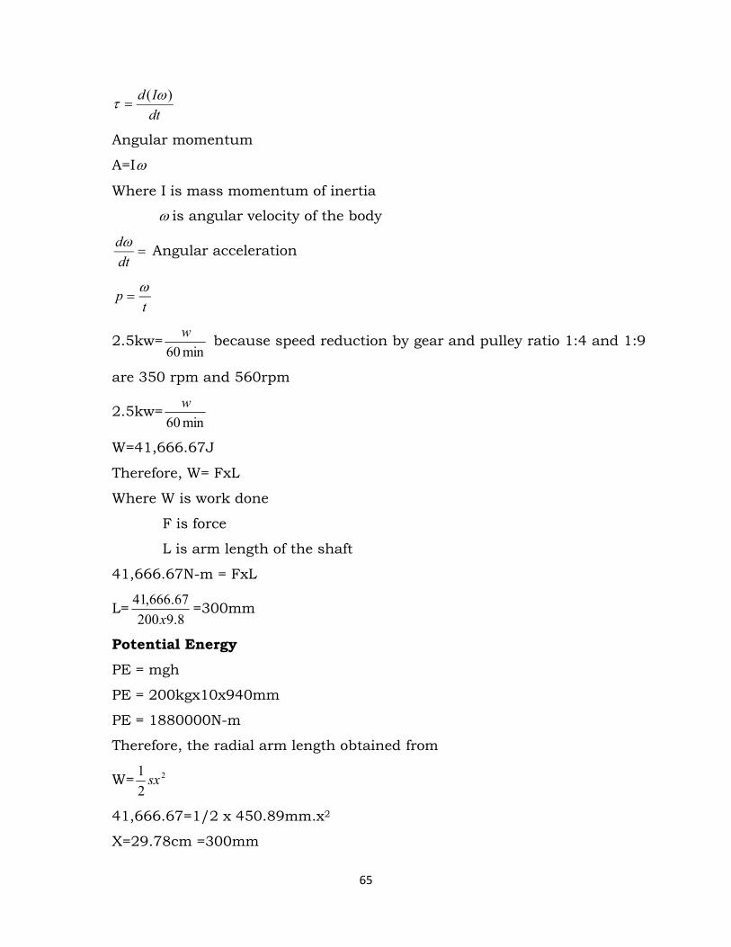
65
dt
Id )(
Angular momentum
A=I
Where I is mass momentum of inertia
is angular velocity of the body
dt
d Angular acceleration
tp
2.5kw=min60
w because speed reduction by gear and pulley ratio 1:4 and 1:9
are 350 rpm and 560rpm
2.5kw=min60
w
W=41,666.67J
Therefore, W= FxL
Where W is work done
F is force
L is arm length of the shaft
41,666.67N-m = FxL
L=8.9200
67.666,41
x=300mm
Potential Energy
PE = mgh
PE = 200kgx10x940mm
PE = 1880000N-m
Therefore, the radial arm length obtained from
W= 2
2
1sx
41,666.67=1/2 x 450.89mm.x2
X=29.78cm =300mm

66
4.4 Ergonomics considerations
Human aspects play an important role in the ergonomic considerations. An
effor thas been made to understand the muscular problems faced by the
workers while manually concret mixing machine
Optimum metrics were obtained for operators of different heights and a
customizable design of our machine is proposed to enhance the
ergonomical considration to the machine. All design decisions were made
based on anthropometric data of an average person.
The design of the machine is mainly aimed to solve the problems such as
musculoskeletal injuries, back strian that come due to the awkward
postures of the traditional and manual method of mixing process by using
crank shaft (handle). The main ergonomics feature in this design is the
presence of a comfortable driving mechanism that suits for medium age
and any sex groups of people.

67
CHAPTER FIVE
MANUFACTURING PROCESS AND ASSEMBLY
This chapter deals with the process and Operation sheet for critical
components, Procedures of assembling components and maintenance of the
project.
5.1 Manufacturing process
Manufacturing process is part of the production process which is directly
concerned with the change of procedure or dimensions of parts being
produced. It is usually carried out as a unit operation, which means that a
single step in the sequence of steps required transforming the starting material
into a final product.
Manufacturing is derived from the Latin word ‘manu-factus’, means made by
hand. In modern context it involves making products from raw material by
using various processes, by making use of hand tools, machinery or even
computers. It is therefore a study of the processes required to make parts and
to assemble them in machines.
5.1.1 General steps to manufacture components of the machine:-
Taking the material for the component according to the design
parameters and material selection.
Assuring the selected material dimension and parameter by proper
measuring tool.
Marking (layingout) the selected material to the recommended
dimensions.
Selecting the appropriate machining process or tool for cutting the
material to prepare the rough dimension.
Keeping selected material in the selected machine or tool to make the
rough dimensions.
Accomplishing the operation within the recommended and measured
dimension on the marked line with recommended allowance.
Making the joining operation (welding, bolt & nut, …)
68
Checking the recommended dimension and parameter.
Polishing the assembled component according to the recommended
finishing process.
Painting if it is necessary
Making ready the component for assembly.
Manufacturing operation
During manufacturing process we have considered the basic manufacturing
steps such as process operation and assembling operation.
The manufacturing process used in the fabrication of the concrete mixing
machine is such that the total cost of fabrication is reducing and also one
that can make use of the available materials. The manufacturing process
involved in this work includes, cutting materials using either hand or power
hack saw, machining, joining of metal parts using welding, bolt and nut.
Each component of the machine is fabricated separately before they
are joined or welded together. The following are the procedure of
fabrication of each component of final products.
Main frame or stand of the machine
The frame supports the entire machine which is made by joining (Length
2200, Width 50, Height 50 and Thickness 2mm) square pipe to make the
overall dimension of it to length 1400, width 980, and height 900mm and
shape it by welding.
Two tires having a height of 190 mm each were welded with the end of
plates attached to tires by bolt 980x40x70mm pipe at the bottom of the
frame of one side for easily movement of the machine. The inclined angles
were designed to 1200 from the horizontal to have better ground gripping.

69
Part number: 01
Material: Steel
Quantity: 1
Figure 5.1 Frame of the machine
Table 5.1 Manufacturing procedure of the body frame
Op. no.
Description of job Tool and
cutter description
Depth of
cut(mm)
Time Machining cost
Setup hrs
Machining time hrs
Rate Birr/hr
Cost Birr
1
0 cut the pipe to
the desired length
cutting end of the pipe to 45 deg. from each layout
combination square, hacksaw
70.7 0.15
0.25
40 6
1 removing the notches to form angle of 120 deg
combination square, hacksaw
67.8 0.25
0.50
35 8.75
2
0 Drill the
holes through
the marked points
Setting up collate chuck, swivel the vertical milling head and drill the holes to diameter 12 and depth 50mm
drill bit, collate chuck
50
0.40 30 12
1 Enlarging the drilled hole to diameter 18mm using larger drill.
50
0.30 0.5 25 7.5
2 finish the hole to diameter 30H7 reamer
0.1 0.2 0.11 20 4
3
0
Join the cut portion
by welding
setting up the welding machine to the recommended ampere 0.2 0.1 0.1 50 5
1 Welding the components ø3.2 electrode 0.9 0.07 0.5 200 100
2
removing slag and chips
chipping hammer, wire brush 0.3 0.04 0.15 30 4.5

70
Main (Drum) shaft manufacturing Process
The procedures to produce the Main (Drum) shaft are:
1. First we prepared a bar of Ø38mm.
2. With a power hack saw, we cut the bar to a length of 260mm.
3. Then, using lathe machine the ends of shaft is faced to produce a length
of 250 mm.
4. Rough turn one end of the shaft to 36.5mm diameter to a length of 250
mm.
5. Finish turns this end of the shaft to 35mm diameter.
6. Set a milling machine to cut key way on the stepped end of the shaft.
7. Using end mill cut a key way of length and width 20mm and 8mm for
pulley respectively.

71
Part number: 02
Material: Mild steel
Quantity: 01
Figure 5.2 Main shaft
Table 5.2 Manufacturing procedure of the main shaft
Op. no.
Description of job
Tool and
cutter description
Depth of
cut(mm)
Speed Time
Machining cost Cutting
speed Feed speed in m/mi
n(RPM)
mm per tooth
mm per rev
Setup hrs
Machining time hrs
Rate Birr/hr
Cost Birr
2
0
Machine the main or drum
shaft
Preparing and cutting Ø38mm bar to a length of 260mm using lathe machine.
lathe cutter
19 96 2546.9
0.15
200 30
1 facing to produce a length of 250 mm.
0.5
0.25
200 50
2 turning one end of the shaft to 36.5mm diameter to a length of 250 mm
0.25
3
Finishing turn the end of the shaft to 35±0.05mm diameter.
0.2
4 Setting a milling machine to cut key way on the stepped end of the shaft.
5
Using end mill, cut a key way of length and width 20mm and 8mm for pulley respectively
Milling
cutter 4 0.1 0.1 50 5

72
Pulleys production
It is one of the machine element used to transmit motion from the smaller pulley
to the driver shaft through V-belt. Since its size is larger than smaller pulley, it
has an advantage of reducing speed of rotation of AC motor by one-fourth to
have less speed on driver and driven shafts. It can be manufactured from
aluminum/cast/by using casting iron process. But we designed to use cast iron
for better strength and durability. For this reason we directly searched and
purchase it from the market due to unavailability of raw materials with specified
material type.
Ø660 660
Material------------AISI1035
Blank size---------Ø305x26 mm 25
Quantity----------- 01
Operation sheet for smaller pulley
It is one of the machine element used to transmit motion from the prime mover
to the larger pulley through V-belt. Since its size is smaller than larger pulley, it
has an advantage of reducing speed of rotation of AC motor by one-fourth to
have less speed on the larger pulley. It is manufactured from aluminum by using
machining process.
Material------------ AISI 1035
Blank size---------Ø80x50 mm
Quantity----------- 01
Figure 5.4 Smaller pulley
Figure 5.3 Larger pulley

73
Table 5.3 Operation sheet for smaller pulley
No. Operation Machine used Tools & Equipment’s used
Dimension
1 Measuring & cutting to size
Power hacksaw
Venire caliper, steel rule
Ø = 80 mm L= 50 mm
2 Facing on one side Lathe machine carbide cutter & V. caliper
Ø = 80 mm L= 48.5 mm
3 Turning and chamfering
Lathe machine Carbide cutter Vernier Caliper
Ø = 75 mm L= 48.5 mm
4 Facing on the other side
Lathe machine Carbide cutter Vernier Caliper
Ø = 75 mm L=47 mm
5 Turning a hub and chamfering
Lathe machine Carbide cutter Vernier Caliper
Ø = 40 mm W= 24 mm
6 Drilling Lathe machine Center drill, Drill bit And V. Caliper
Ø =24 mm D= 47 mm
7 Milling a key way Milling machine
Slotting attachment with HSS cutter
6x3.5x47 mm
Mixing blade production
It is one of the machine components of concrete mixing machine which is made
from mild steel plate with 6 mm thickness. The purpose of mixing blade is to stir
aggregates, cement, sand and water during mixing or combining. They play a
significant role in making the concrete with homogeneous output. They are three
in number attached to the side of the drum by bolt and nut.
Operation sheet for mixing blade
Material: AISI 1820
Blank size: 500x40x6mm
Quantity: 03
Figure 5.5 Mixing blade

74
Table 5.4 Operation sheet for mixing blade
No.
Operation
Machine used
Tools & Equipments used
Dimension
1 Measuring & cutting to size
Hand shear Steel rule and tape rule
W= 50mm L= 500 mm
2 Drilling Bench type drilling machine
M10 Ø10 mm Center to center 452mm
3 Connecting with drum
Bolt and nut of M10
Adjustable wrench
Gear manufacturing
Gears are used extensively for transmission of power. They find application in
automobiles, oil engines, machine tools, industrial machinery, agricultural
machinery, geared motors, etc. To meet the strenuous service conditions the
gears should have robust construction, reliable performance, high efficiency,
economy and long life. Also, the gears should be fatigue free and free from high
stresses to avoid their frequent failures. Gear drives should be free from noise,
chatter and should ensure high load carrying capacity at constant velocity
ratio.
Spur gears are the most common type, which transmit power or motion
between parallel shafts or between a shaft and a rack. They are simple in
design and measurement. In our machine, the shafts are parallel and
revolution per minute is low and no significant noise.
Figure5.6.Spur gear
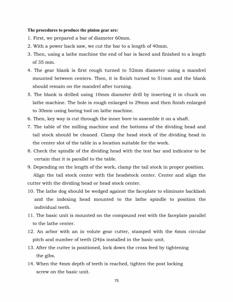
75
The procedures to produce the pinion gear are:
1. First, we prepared a bar of diameter 60mm.
2. With a power hack saw, we cut the bar to a length of 40mm.
3. Then, using a lathe machine the end of bar is faced and finished to a length
of 35 mm.
4. The gear blank is first rough turned to 52mm diameter using a mandrel
mounted between centers. Then, it is finish turned to 51mm and the blank
should remain on the mandrel after turning.
5. The blank is drilled using 10mm diameter drill by inserting it in chuck on
lathe machine. The hole is rough enlarged to 29mm and then finish enlarged
to 30mm using boring tool on lathe machine.
6. Then, key way is cut through the inner bore to assemble it on a shaft.
7. The table of the milling machine and the bottoms of the dividing head and
tail stock should be cleaned. Clamp the head stock of the dividing head in
the center slot of the table in a location suitable for the work.
8. Check the spindle of the dividing head with the test bar and indicator to be
certain that it is parallel to the table.
9. Depending on the length of the work, clamp the tail stock in proper position.
Align the tail stock center with the headstock center. Center and align the
cutter with the dividing head or head stock center.
10. The lathe dog should be wedged against the faceplate to eliminate backlash
and the indexing head mounted to the lathe spindle to position the
individual teeth.
11. The basic unit is mounted on the compound rest with the faceplate parallel
to the lathe center.
12. An arbor with an in volute gear cutter, stamped with the 6mm circular
pitch and number of teeth (24)is installed in the basic unit.
13. After the cutter is positioned, lock down the cross feed by tightening
the gibs.
14. When the 4mm depth of teeth is reached, tighten the post locking
screw on the basic unit.

76
15. The cutter is then fed into the blank by hand using the lathe carriage
wheel.
16. The procedures are continued until all the teeth are cut and
completed.
The standard bearing house
Figure 5.7 Standard bearing House (Catalogue Oko,2005)
The standard bearing house with its bearing is selected for our project was
bought from the local market. The selected bearing is self centered type and
can resist the load radial on the shaft. The size of the bearing and bearing
house selected is based on the standard values indicated on the above table. As
it was indicated on the standard table above, the housing number SNG507-606
is appropriate for the shaft diameter of 30 mm. So that, the selected bearing
house for the project is the housing number of SNG507-606.
Note: The operation sheet for other parts like driven shaft, motor basement,
drum basement, stud bolt, frame, and handle is similar to the operation sheet
of parts mentioned above based on size, operation, tools and machines
required and their operation sequences are explained in Labor cost for
manufacturing components.

77
Sequence of manufacturing processes
The activities mentioned by table below by table were critical activities and
concern has been given to complete the project in time. Thus, the total
production time is 136Hr.
Table.5.6 : Sequence of manufacturing processes of the components and
assembling of mini concrete mixer machine in time estimates.
Activities Activities description Duration Hr
A Producing Main frame of the machine 16Hr B drum basement 8Hr C motor basement 12Hr D Drum 12Hr E Shaft 10Hr
F Pulley 8Hr
G Producing handle 8Hr H crank shaft 1Hr I Assembling all components 12Hr
Activities A and B can start simultaneously. Activity A followed by D, E, and F.
Activity B is followed by activity C,G and H.
Table 5.7 Activities
Activity A B C D E F G H I
Optimistic
time(t1)
16 8 12 12 10 8 8 1 12
Most likely
time(t2
16 8 12 12 10 8 10 1 12
Pessimistic
time(t3)
17 12 14 14 12 10 16 2 14
Expected time =
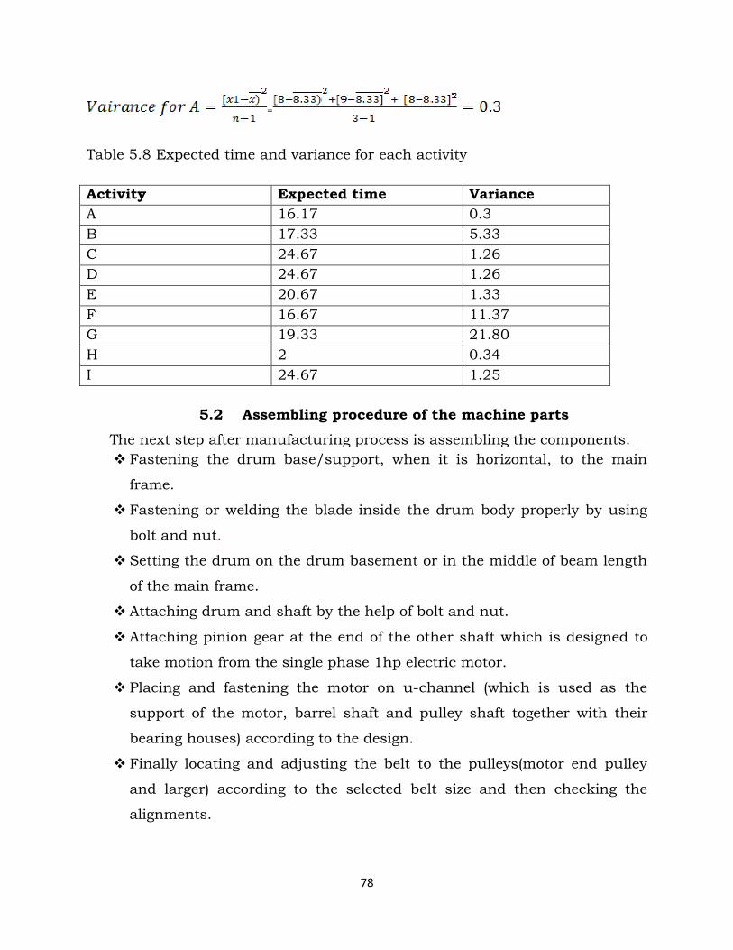
78
=
Table 5.8 Expected time and variance for each activity
Activity Expected time Variance
A 16.17 0.3
B 17.33 5.33
C 24.67 1.26
D 24.67 1.26
E 20.67 1.33
F 16.67 11.37
G 19.33 21.80
H 2 0.34
I 24.67 1.25
5.2 Assembling procedure of the machine parts
The next step after manufacturing process is assembling the components.
Fastening the drum base/support, when it is horizontal, to the main
frame.
Fastening or welding the blade inside the drum body properly by using
bolt and nut.
Setting the drum on the drum basement or in the middle of beam length
of the main frame.
Attaching drum and shaft by the help of bolt and nut.
Attaching pinion gear at the end of the other shaft which is designed to
take motion from the single phase 1hp electric motor.
Placing and fastening the motor on u-channel (which is used as the
support of the motor, barrel shaft and pulley shaft together with their
bearing houses) according to the design.
Finally locating and adjusting the belt to the pulleys(motor end pulley
and larger) according to the selected belt size and then checking the
alignments.

79
Figure 5.9 Isometric drawing of the object

80
Subassemblies of the machine
1. Main frame
2. Revolving drum
3. Mixing blade
4. Drum basement
5. Motor basement
6. Motor
7. Hand lever
8. Manual hand driven
The Steps to disassemble the machine components are:
I. Removing the belt from the motor and pulley with safety
consideration.
II. Removing the main shaft from the drum.
III. Disassembling main shaft and bearing house and then by
loosening the bolts from the u-channel.
IV. Loosening the bolts to disassemble larger pulley, pinion gear and
their shaft.
V. Then taking out the shaft, bearing house (bearing) and pulley
together from the u-channel.
VI. Removing the bearing house (bearing) from the shaft connected to
the discharging lever.
VII. Loosening the mixing blade from inside of the drum.
VIII. Then complete the disassembling mechanism with the required
safety procedures.

81
CHAPTER SIX
COST ANALYSIS AND TEST RESULT
In our project, cost refers to the amount of money invested in the production of
the machine. The analysis of this cost may help someone who wants to produce
the same machine or to make another design by considering the amount used
in this machine as reference or starting cost.
6.1 Cost Analysis
Cost of frame
The cost for body frame is shown in the table below.
Table 6.1 Cost of frame
No. Item Quantity Unit cost Total cost
1 Mild steel square hollow section 50mm x50mm x 1.5mm
2pcs 420 840
2 Electrode 1pack 220 220
3 Hole drilling by using portable drill 0.5hrs 30.0 15
4 Cutting using hack saw 2hrs 30.0 60
5 Welding using shielded metal arc welding machine
3hrs 30.0 90
Total Cost 1225.00
Cost of Drum support
Table 6.2 Cost of drum support
No. Item Quantity Unit cost Total cost
1 Mild steel square hollow section 40mm x40mm x 1.5mm
2pcs 380 760
2 Electrode 1pack 220 220
3 Cutting using hack saw ½ hrs 30.0 15
4 Welding using shielded metal arc welding machine
1½ hrs 30.0 45
Total Cost 1040.00

82
Cost of discharging lever
Table 6.3 Cost of discharging lever
No. Item Quantity Unit cost Total cost
1
Mild steel round solid bar of
Ø30mm and length 1000mm 1pc 320 320
2 Hole drilling by using portable drill 0.5hrs 30.0 15
3 Cutting using hack saw 0.75hrs 30.0 22.5
Total Cost 357.50
Cost of blade guiding shaft
Table 6.4 Cost of blade guiding shaft (inside the drum)
No. Item Quantity Unit cost Total cost
1 Mild steel round solid bar of Ø25mm and length 400mm
1pc 280 280
2 Electrode 10pcs 2 20
3 Cutting using hack saw ½ hrs 30.0 15
4 Welding using shielded metal arc welding machine
½ hrs 30.0 15
Total Cost 330.00
Cost of U-Channel
Table 6.5 Cost of u-channel
No. Item Quantity Unit cost Total cost
1 Mild steel of section 1500x80x5mm
1pc 120 120
2 Electrode 20pcs 2 40
3 Cutting using hack saw ½ hrs 30.0 15
4 Welding using shielded metal arc welding machine
¼ hrs 30.0 7.5
Total Cost 182.50

83
Cost of rotating handle
Table 6.6 Cost of rotating handle
No. Item Quantity Unit cost Total cost
1
Round hollow pipe of section
Ø30mm and length 700mm 1pc 190 190
2 Electrode 8pcs 2 16
3 Cutting using hack saw ½ hrs 30.0 15
4
Welding using shielded metal arc
welding machine ½ hrs 30.0 15
Total Cost 236.00
Cost of motor pulley
Cost of shafts
Cost of stock = V =A * L
V = 322 25.406,2402505.17 mmxxxlr =0.00024m3 where r is radius and
l is length of the shaft respectively.
= 7800kg/m3 for iron
m = *v =7800kg/m3x0.00024m3=1.872kg
No Item Quantity Unit cost Total cost
1 Aluminum Ingot 1pc 200 200
2 HSS Cutter 1pc 60 60
3 Machining by using lathe machine
3hrs 40 120
Total cost 400.00

84
1kg = 170 birr,
170*1.872=318.24 birr
318.24 x4 = 1,272.96, because the quantity of the shaft is four
It took around 320 birr for machining and the overall cost becomes
1,592.96 birr.
Cost of tires Connection
Table 6.8. Cost of tires connection
No. Item Quantity
Unit cost
Total cost
1 Electrode 10pcs 2 20
2 Welding with shield metal arc welding
15min 30 7.5
Total cost 27.5 birr
Cost of mixing blade
Table 6.9 Cost of mixing blade
No Item Quantity Unit cost Total cost
1 Flat plate 500mmx50mm x 6mm 3 35 105
2 Cutting by hack saw 0.125hrs 25 3.125
3 Drilling using drilling machine 0.25hrs 35 8.75
Total cost 116.875
birr
Cost of components bought from local market
Sometimes it is difficult to manufacture some parts due to unavailability
of materials, machines to produce them, and etc. for this reason we
directly purchased them from local market.
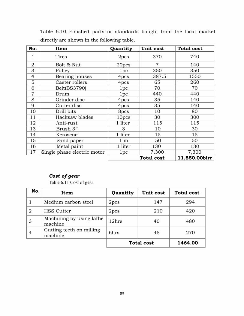
85
Table 6.10 Finished parts or standards bought from the local market
directly are shown in the following table.
No. Item Quantity Unit cost Total cost
1 Tires 2pcs 370 740
2 Bolt & Nut 20pcs 7 140 3 Pulley 1pc 350 350 4 Bearing houses 4pcs 387.5 1550 5 Caster rollers 4pcs 65 260 6 Belt(BS3790) 1pc 70 70 7 Drum 1pc 440 440 8 Grinder disc 4pcs 35 140 9 Cutter disc 4pcs 35 140 10 Drill bits 8pcs 10 80 11 Hacksaw blades 10pcs 30 300 12 Anti-rust 1 liter 115 115 13 Brush 3’’ 3 10 30 14 Kerosene 1 liter 15 15 15 Sand paper 1 m 50 50 16 Metal paint 1 liter 130 130 17 Single phase electric motor 1pc 7,300 7,300
Total cost 11,850.00birr
Cost of gear
Table 6.11 Cost of gear
No. Item Quantity Unit cost Total cost
1 Medium carbon steel 2pcs 147 294
2 HSS Cutter 2pcs 210 420
3 Machining by using lathe machine
12hrs 40 480
4 Cutting teeth on milling machine
6hrs 45 270
Total cost 1464.00

86
Total cost
Table 6.12 Total cost
No Item Cost(Birr) 1 Cost of frame 1225.00 2 Cost of drum
support/basement 1040.00
3 Cost of discharging lever 357.50 4 Cost of blade guiding shaft 330.00 5 Cost of u-channel 182.50 6 Cost of rotating handle 236.00 7 Cost of motor pulley 400.00 8 Cost of shafts 1592.00 9 Cost of tires connection 27.5 10 Cost of mixing blades 116.875 11 Cost of components bought
from local market 11,850
12 Cost of gears 1464.00 Total Cost 18,821.375
Contingencies: - it is compensation due to some errors and unexpected failure
of time in our project. It is usually taken as 10% of the manufacturing cost.
Contingency = 10%18,821.375 Birr
= 100
1018,821.375 Birr
Contingency = 1,882.1375 so that, overhead and labor
cost is included or considered to be in contingency cost
Total manufacturing cost = Manufacturing cost +
Contingency
= 18,821.375 Birr + 1,8820.1375Birr
= 20,703.5125 Birr
Profit: - it is usually taken as 20% of the total cost.
Profit = 100
2020,703.5125Birr
Profit = 4,140.7025 Birr
Selling price = Profit + Total manufacturing cost = 4,140.7025+20,703.5125 Birr
=24,844.215 Birr
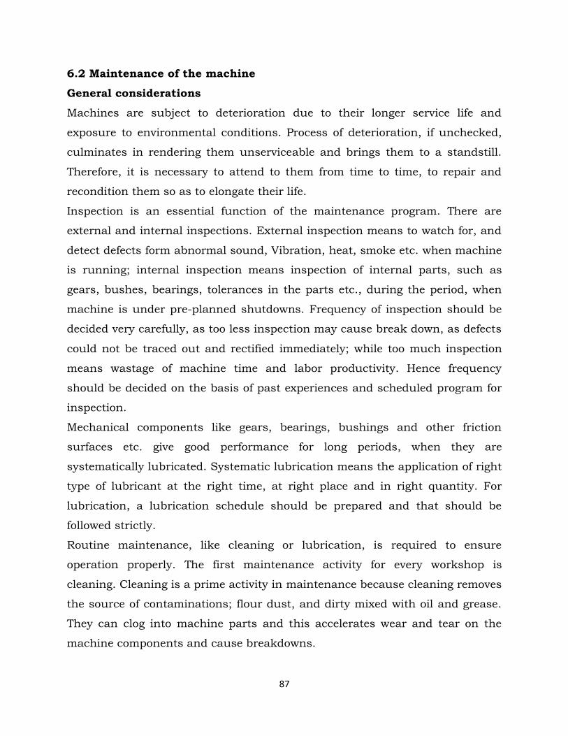
87
6.2 Maintenance of the machine
General considerations
Machines are subject to deterioration due to their longer service life and
exposure to environmental conditions. Process of deterioration, if unchecked,
culminates in rendering them unserviceable and brings them to a standstill.
Therefore, it is necessary to attend to them from time to time, to repair and
recondition them so as to elongate their life.
Inspection is an essential function of the maintenance program. There are
external and internal inspections. External inspection means to watch for, and
detect defects form abnormal sound, Vibration, heat, smoke etc. when machine
is running; internal inspection means inspection of internal parts, such as
gears, bushes, bearings, tolerances in the parts etc., during the period, when
machine is under pre-planned shutdowns. Frequency of inspection should be
decided very carefully, as too less inspection may cause break down, as defects
could not be traced out and rectified immediately; while too much inspection
means wastage of machine time and labor productivity. Hence frequency
should be decided on the basis of past experiences and scheduled program for
inspection.
Mechanical components like gears, bearings, bushings and other friction
surfaces etc. give good performance for long periods, when they are
systematically lubricated. Systematic lubrication means the application of right
type of lubricant at the right time, at right place and in right quantity. For
lubrication, a lubrication schedule should be prepared and that should be
followed strictly.
Routine maintenance, like cleaning or lubrication, is required to ensure
operation properly. The first maintenance activity for every workshop is
cleaning. Cleaning is a prime activity in maintenance because cleaning removes
the source of contaminations; flour dust, and dirty mixed with oil and grease.
They can clog into machine parts and this accelerates wear and tear on the
machine components and cause breakdowns.

88
Preventive maintenance activities of the Concrete Mixing machine
Table 6.13 Preventive maintenance activities
No.
Activities (detail of work)
Frequency
Estimated
time
Comment
1 ELECTRICAL
Check operation of start/stop
switch.
5 weeks 30 minutes
2 MECHANICAL
Transmission gear check up 2 weeks 1hrs
Lubrication system check up for
bearings
1 weeks 1hrs
Check up for belt tension 2weeks 20 minutes
check up for blades 1 week 1hr
check up for drum guiding rollers 2weeks 2hrs
check up for loosened bolts and nuts 4days 1hr
Checkup for pulleys 2weeks 20 minutes
List of spare parts required for repairing
The principal spare parts that are required frequently to change when parts are
worn out through long time performance are: bearings, belts, guiding rollers
and blades. These parts can be easily manufactured to satisfy customer
demand with respect to the entire machine.

89
SAFETY
Good slogan of safety states that “it is better to be safe than sorry!”
With respect to safety, everything has its own way of safe working condition.
Therefore, the machine may cause injury, unexpected damage or strike to the
human body if it is wrongly operated or safety consideration is poor. Among
which the revolving belt may caught clothes, if something like tools or other
materials were kept over the revolving part of the machine before start and
unknowingly, these parts may be thrown and cause accident after the machine
started running and etc. to avoid these and such;
All necessary parts should be in place after use and in separate place far
from the machine during the machine is running
All bolts should be tightened.
The output should always be in the down position. There is no reason
why it should be in the upright position after mixing.
Ensure that the motor throttle is set in its off position and it is
recommended that the spark plug wire be disconnected and kept away
from the spark plug.
Warning: Never start the machine if anything is kept inside the machine other
than the necessary operation. This could result in injury or damage to the
operator.
Working Principles
Starting and Running the Mixer
1) Ensure that all the mixer components are properly assembled and ready
for operation.
2) Rotate the drum by hand to make sure that there are no restrictions to
rotation.
3) Remember to tension the belt (the slack side of the belt) and make sure
that the belt is seated properly in all pulleys and is not rubbing on
anything.
4) Start the machine and observe the situation of the machine and if it is safe

90
start loading inputs of the concrete.
5) After proper mixing process push the discharging lever downward to unload
the mixture all in all while the machine is running.
6) Release the discharging lever slowly until the machine returns its normal
position.
7) Continue mixing by following the above steps but make sure that the drum
is empty before loading the subsequent process.
Troubleshooting
I. Problem: Excessive vibration
Solution
Check whether the drum is rotating over the roller or not.
Check all bolts of bearing house are tightened.
Check pulleys and belt system.
II. Problem: the pulley is not rotating
Solution
Check the motor seat to properly fix at the right position in order to
tight properly with pulley.
Check whether the motor is rotating or not.
III. Problem: Belt deterioration or breaking prematurely(Check belt or pulley
manufacture’s catalog for full detailed list.)
Solution
Check for foreign objects in the drive; make sure that the guard is
installed.
Check for oil or grease on belts. Clean belts and sheaves with a
degreasing agent or detergent and water. Remove the source of oil or
grease
Re‐tension the belt.
91
CHAPTER SEVEN
CONCLUSION AND RECOMMENDATION
7.1. Conclusion
The demand of this machine is higher and it is the time to respond for the
concrete mixer workers’ problem. It can solve the exhausting manual concrete
processing tasks and saves time. It can also facilitate products with pure
inputs without adding dusts or other foreign materials. This concrete mixer
machine has two functions; namely, manual mixing in the absence of
electricity and electrical or self rotating. Therefore the design best meets the
country’s demand in order to alleviate problems of heterogeneous concrete
production specially using shovel to mix. Since the main function of this
machine is to process concrete for construction industry workers it can
facilitate productivity and it increases quality as well. One of the major
problems in our country is ineffective use of resources that result in cracking of
some part of building, cracking of parts of bridges and etc arise from improper
mixing or producing of heterogeneous concrete. This is due to addition of dusts
and foreign materials during mixing when it is used the oldest method in order
to facilitate the production time faster.
The machine is tested for its functionality and in the first test of mixing, all the
concrete inputs were loaded while the machine was running and discharged
after proper mixing time and thus we got the machine is ready for the next
batches except the speed was slightly higher than intended or required for
proper mixing even if it is not exaggerated. Whatever the machine is technically
feasible. Thus, the project is functional as per the design.
The machine can perform the following activities:
Move from place to place easily by the help of tires attached to one side of
the frame.
Mix to the required ratio manually or electrically

92
This machine has also the following advantages:
o Manufactured from local materials
o Easy to assemble and disassemble.
o It does not need highly skilled manpower.
o Convenient for transportation.
o Low in cost and easy to maintain.
o Having two functions (manual and electrical) leads not to buy two
different machines, this helps to save time and money.
o It can create job opportunity.
It can be easily manufactured and distributed to various areas of our
country and easily adapted as technology transfer to SMEs.
7.2. Recommendation
This small scale or mini concrete mixing machine is designed to optimize
effective utilization of concrete and its constituents which are vastly wasted in
rural areas where inputs are mixed manually using shovel in large volume
without considering producing foreign material free concrete. Furthermore, the
machine is proposed to produce in TVET and Small and micro Enterprises to
duplicate for the concrete using community. Besides, this technology is
believed to enhance and support medium level construction companies or
contractors in producing quality concrete.
In addition to what had been indicated in this project work, we would like to
recommend the following points:
This design is a small scale, so it can be enlarged to increase its capacity
or volume of production.
This design can be changed by considering some practical aspects like
using belt and pulley only without gear in order to ease production.
When the power rating (kwh) of the machine is increased for large scale
machines, the revolution per minute (rpm) also increases and hence, this
maximizes the capacity of production. Therefore, we recommend large
power ratings for larger machines.

93
In towns, small and micro enterprises (SME) can manufacture and
multiply the machines for construction sector to produce easily producible
concrete.
Rural and urban development experts at different levels can create
awareness for easy dissemination of the technology in to rural areas
because the machine was designed to work electrically and manually.
Medium level construction contractors owning large capital can purchase
and employ the machine while others can purchase in team to utilize the
machine.

References
[1] R. Sonnenberg, Concrete mixers and mix systems, Concr. Precast
Plant Technol. 64, 88-98 (1998).
[2] C. F. Ferraris and C. Lobo, Processing of HPC, Concr. Int. 20 (4), 61-
64 (1998).
[3] H. Beitzel, Concrete production plants and mixers some aspects of
their design and operation, Part 2, Beton + Fertigteil-Technik 5, 305-
310 (1984).
[4] ACI Committee 304, Guide for the use of volumetric-measuring and
continuous-mixing concrete equipment, ACI (1991).
[5] Standard test method for slump of hydraulic cement concrete, ASTM
C143-90, 04.02 (1990).
[6] G. Larose and M. Pigeon, Be´ton produit en be´tonnie`re mobile et en
usine conventionelle. Comparison des carate´ristiques du re´-seau de
bulles d’air, Can. J. Civ. Eng. 15 (3), 306-314 (1988).
[7] A. M. Paillere, J. J. Serano, and M. Grimaldi, Influence of dosage and
addition method of superplasticizers on the workability retention of
high strength concrete with and without silica fume, in Proc. of Int.
RILEM symp. Admixtures for Concrete: Improvement of Properties, E.
Va´squez, ed., Chapman and Hall, London (1990) pp. 63-79.
[8] Y. Charonnat and H. Beitzel, RILEM TC 150 ECM: Efficiency of
concrete mixers; report: efficiency of concrete mixers towards
qualification of mixers, Mater. Struct. (Suppl. 196) 30, 28-32 (1997).
[9] J. A. Orban, P. A. Parcevaux, and D. J. Guillot, Specific mixing energy:
a key factor for cement slurry quality, 61st annual Technical
Conference and Exhibition of the SPE, SPE-15578 (1986) pp. 1-8.
[10] T. Osterberg, Measurements of properties of fresh high performance
concrete and effects of the mixing process, Special Concretes:
Workability and Mixing, Bartos, ed., Spon London (1993) pp. 17-30.
[11] S. Soga and K. Takagi, Influence of the mixing energy on fresh
concrete, Trans. Jap. Concr. Inst. 8, 73-80 (1986).

[12] O. Peterson, Swedish method to measure effectiveness of concrete
mixers, Special Concretes: Workability and Mixing, Bartos, ed., Spon
(1993) pp. 39-48.
[13] P. Bartos, Fresh concrete: properties and tests, Elsevier, New York
(1992).
[14] A. Johansson, The Relationship between mixing time and the type of
concrete mixer, Natl. Swed. Build. Res. Summaries T1: 1971 (1971).
[15] Hunker, Henry L. (2000). Columbus, Ohio: A Personal Geography.
Ohio State University Press. p. 196. ISBN 978-0-8142-0857-1.
[16] "Control Technology for Ready-mix Truck Drum Cleaning" (PDF). U.S.
Department of Health and Human Services. 31 May 2001. Retrieved
21 October 2013.
[17] Portland Cement Association: History of Ready Mixed Concrete
Industry site
[18] Casey, Jon M. "Parmer Metered Concrete offers precision and
quality". Hard Hat News. Retrieved 24 November 2014.
[19] "MacGyver" Legend of the Holy Rose: Part 1 (1989)

APPENDIX A
Adama Science and Technology University
School of Mechanical and chemical Engineering
Department of Mechanical and Vehicle engineering
Questionnaire
Dear respondents: Concrete mixer is a machine used to mix aggregates,
cements and water in order to provide concrete for construction and
building industry. This is M.Sc thesis project questionnaire aimed at
identifying the current concrete mixer problems in building and
construction industry of the country.
So, you are kindly requested to fill the questionnaires as per the instruction
given for each item. If you would like to change any of your response to a
question, please do so by clearly crossing the incorrect response and
making the response you intend. Note that:
You are not required to write your name.
Put () mark in the box/cell for questions with options, and
write briefly whenever necessary.
You have to return the questionnaire to the person from
which you received as soon as possible after completion.
Thank you!!!

Part I. Tick (√ or x) in the given box.
በሚስማማዎት ሳጥን ዉስጥ የ() ምልክት ያስቀምጡ!
I. Personal characteristics
የግል መረጃ
1. Sex: Male Female ፆታ፡ ወንድ ሴት
2. Age: 15 -20 21 – 30 31 – 40 Above 40
እድሜ
1. Educational qualification level: የትምህርት ደረጃ
- Under graduate (Degree) Diploma
ድግሪ ድፕሎማ
- Postgraduate (Master) Certificate By experience ማስተርስ ሰርቴፊኬት በልምድ
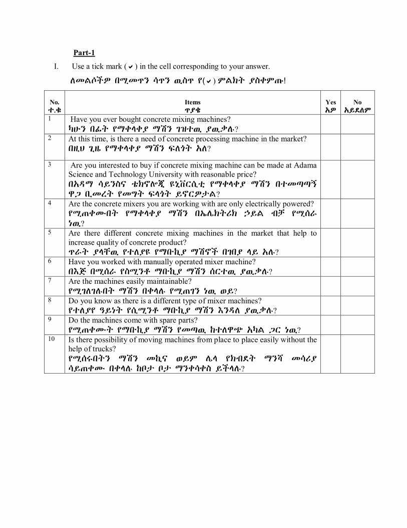
Part-1
I. Use a tick mark () in the cell corresponding to your answer.
ለመልሶችዎ በሚመጥን ሳጥን ዉስጥ የ() ምልክት ያስቀምጡ!
No. ተ.ቁ
Items ጥያቄ
Yes አዎ
No
አይደለም 1 Have you ever bought concrete mixing machines?
ካሁን በፊት የማቀላቀያ ማሽን ገዝተዉ ያዉቃሉ?
2 At this time, is there a need of concrete processing machine in the market? በዚህ ጊዜ የማቀላቀያ ማሽን ፍለጎት አለ?
3 Are you interested to buy if concrete mixing machine can be made at Adama Science and Technology University with reasonable price?
በአዳማ ሳይንስና ቴክኖሎጂ ዩኒቨርሲቲ የማቀላቀያ ማሽን በተመጣጣኝ ዋጋ ቢመረት የመግት ፍላጎት ይኖርዎታል?
4 Are the concrete mixers you are working with are only electrically powered? የሚጠቀሙበት የማቀላቀያ ማሽን በኤሌክትሪክ ኃይል ብቻ የሚሰራ ነዉ?
5 Are there different concrete mixing machines in the market that help to increase quality of concrete product? ጥራት ያላቸዉ የተለያዩ የማቡኪያ ማሽኖች በገበያ ላይ አሉ?
6 Have you worked with manually operated mixer machine?
በእጅ በሚሰራ የስሚንቶ ማቡኪያ ማሽን ሰርተዉ ያዉቃሉ?
7 Are the machines easily maintainable?
የሚገለገሉበት ማሽን በቀላሉ የሚጠገን ነዉ ወይ?
8 Do you know as there is a different type of mixer machines? የተለያየ ዓይነት የሲሚንቶ ማቡኪያ ማሽን እንዳለ ያዉቃሉ?
9 Do the machines come with spare parts?
የሚጠቀሙት የማቡኪያ ማሽን የመጣዉ ከተለዋጭ አካል ጋር ነዉ?
10 Is there possibility of moving machines from place to place easily without the help of trucks?
የሚሰሩበትን ማሽን መኪና ወይም ሌላ የክብደት ማንሻ መሳሪያ ሳይጠቀሙ በቀላሉ ከቦታ ቦታ ማንቀሳቀስ ይችላሉ?

Part II
1. Where the machines you are using do made in? _________________________
የሚገለገሉበት ማሽን የየት ሀገር ስሪት ነዉ?
2. How do you feel if manually operated concrete mixing machine is designed and
produced to have an alternative where there is no/interruption of electricity?
መብራት በለሌ ጊዜ ሊያገለግል የሚችል አማራጭ የማቡኪያ ማሽን ቢሰራ
ምን ይሰማዎታል ወይም እንዴት ያዩታል?
__________________________________________________________________
__________________________________________________________________
3. Who control the maintenance activity of the machine?
የማሽኑን ጥገና አስመልክቶ በስራዎ አካባቢ የሚቆጣጠረዉ ሰዉ ማን ነዉ?
______________________
4. Is there problems related to concrete mixing machine you faced?
ከሚገለገሉበት ማቡኪያ መሳሪያ ጋር ተያይዞ ያጋጠመዎት ችግር አለ? -
_____________
If your answer for question number 5 is “yes”, list some of them.
______________________________________________________________________________
______________________________________________________________________________
_________.
Thank You!

Appendix B
Detail drawings
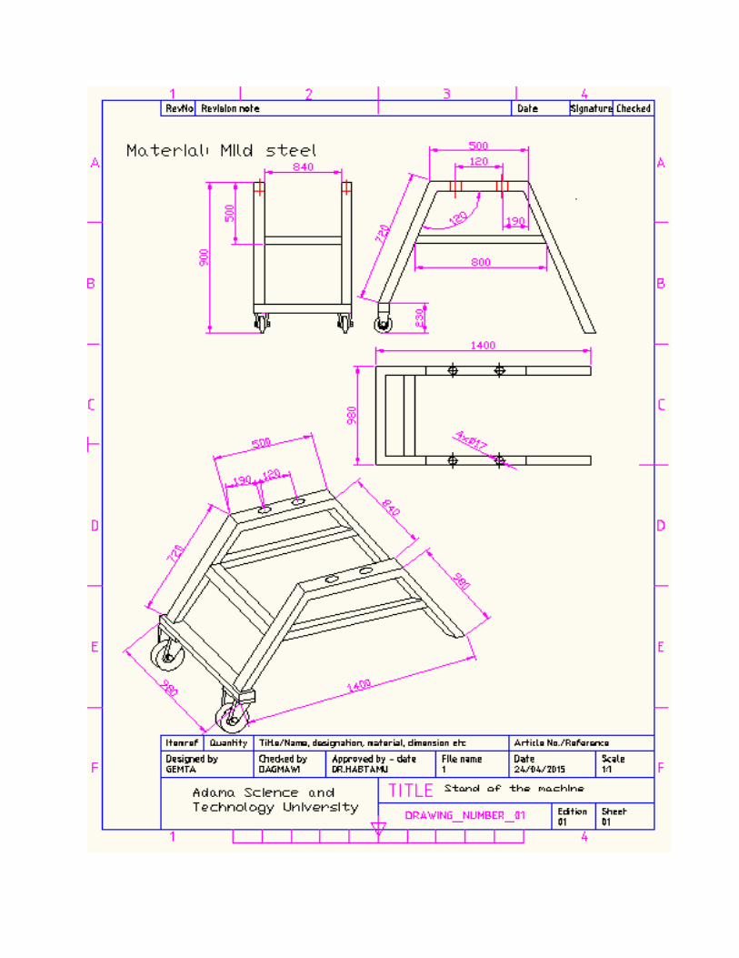


Appendix C
Standard bearing house