ENGINEERED PRECAST
MANUFACTURED
100% INDOORS WITH CONTROLLED CONDITIONS
FAST AND EASYINSTALLATION
ASSUREDQUALITY
REDUCED RISK

decastltd.com
BOXCULVERTS
APPLICATIONS• Conveyance of storm water from urban developments• Designed for gravity fl ow of fl uids• Can be used as small bridges and for stream crossing where natural stream bed does not have to be maintained
STANDARD(S) REFERENCES
ADDITIONAL INFORMATIONContact us at [email protected] for:
• Box culvert sizes, not listed on next page• 3-sided box culverts• Special loading conditions (increased depth of cover, railway loading, other special loading conditions)• Post tensioned box culverts
DIMENSIONSOPSS Design: standard length of sections is 2.44mDECAST Design: standard length of sections is 2.5m
OPSS DESIGN
SPAN X RISE (mm)
WALL THICKNESS (mm)
APPROX. MASS (kg/m)
1800 x 900 200 3,380
1800 x 1200 200 3,690
2400 x 1200 200 4,560
2400 x1500 200 4,870
2400 x 1800 200 5,170
3000 x 150 250 6,860
3000 x 1800 250 7,250
3000 x 2100 250 7,630
3000 x 2400 250 8,020
DECAST DESIGN
SPAN X RISE (mm)
WALL THICKNESS (mm)
APPROX. MASS (kg/m)
3600 x 2400 300 10,130
3600 x 3000 300 11,010
3600 x 3600 300 11,900
3600 x 4200 300 12,780
4200 x 2400 300 11,010
4200 x 3000 300 11,900
4200 x 3600 300 12,780
4200 x 4200 300 13,660
4800 x 2400 350 14,140
4800 x 3000 350 15,160
4800 x 3600 350 16,190
4800 x 4200 350 17,220
5400 x 2400 350 15,160
5400 x 3000 350 16,190
5400 x 3600 350 17,220
5400 x 4200 350 18,250
• Plant Prequalifi cation Program
• OPSS 1821• CSA S6 – CHDBC
• OPSS 422• ASTM C1433• CSA A23.4
• Bends• Reducers & Increasers• Radius Sections• Beveled Ends• Scribed Holes
• Flush Ends• Maintenance Hole Tees• Plugs and Caps• Dowels and Inserts - 15 M
FEATURES AVAILABLE ON REQUEST

decastltd.com
O-SeriesTM 4 - 20
20 - 27
1.0 - 4.2
3.2 - 6.4
3.1-63.7(13 - 65) (3.2 - 13.8) (33 - 685)
51.1 - 134.0(66 - 87) (10.5 - 21) (550 - 1442)
Hydraulics, clear spans, grade separations
Longer span hydraulics, clear spans, gradeseparations
O-SeriesTM
Twin Leaf
PREC
AST
RISE
CLEA
R RI
SE O-SERIESTM PRECAST BRIDGE UNIT
INVERT ELEVATION
BOTTOM OF ARCH
TOP OF ARCH
PRECAST SPANFOUNDATION WITHONE-SIDED KEYWAY
BOTTOM OF LEG
BOTTOM OF FOOTING
APPLICATIONS SPANm (ft)
RISEm (ft)
WATERWAYAREA m2 (ft2)PRECAST BRIDGE UNIT
FOUNDATION WITHONE-SIDED KEYWAY
DE-SPAN ®MODULAR PRECAST BRIDGES & CULVERTS
O-SERIESTMMODULAR PRECAST BRIDGES & CULVERTS
ADDITIONAL FEATURES & INFORMATION
snoitces dewekS •sgniliar dna sbals hcaorppa ,sliardraug rof stresni tsaC •
• Wingwalls, headwalls and footings dna gnippihs ,ngised no tnedneped snoisnemid noitceS •
context of installation
DIMENSIONS
SERVICESNAPS-ED rof sgniward larutcurts laniF •
•
® are sealed (stamped) by a Professional Engineer. DECAST holds a Certifi cate of Authorization licence #11600360, issued by Professional Engineers Ontario
• Installation assistance and consultation can be provided
APPLICATIONS • Small bridge construction and replacement
FEATURES AND BENEFITS• Fully engineered, modular system• Rapid installation• Precast Footings & Express Foundations• Outward horizontal reactions – one-sided keyway, reduced forming and grouting• Maximized clear span and clear distance between footings• Lower installation and maintenance costs• Three-sided structure provides a natural bottom for environmental applications
• Underpasses / overpasses for roads, stream crossings(to preserve natural streambed), pedestrian walkways
Precast Footings & Express Foundations
Span 4 m to 16 m
Rise 0.9 m to 3.6 m
Laying Length 1.2 m to 2.5 m
Leg Thickness 250 mm minimum
Deck Thickness 300 mm minimum
Haunch Length 1371 mm, 2032 mm, 4270 mm

decastltd.com
A PRECAST CONCRETE RETAINING WALL SYSTEM DESIGNED TO MEET DEMAND FOR MINIMALEXCAVATION REQUIREMENTS
• Wall Face 1.22m x 2.44m (4′ x 8′)
• Wall Height 1.22m to 12.20m (4′ to 40′)
• Stem Length 1.83m to 6.10m (6′ to 20′)
• Traffic Barrier 0.91m or 1.07m (3′ or 3.5’)
decastltd.com
GRAVIX®
PRECAST WALL SYSTEM
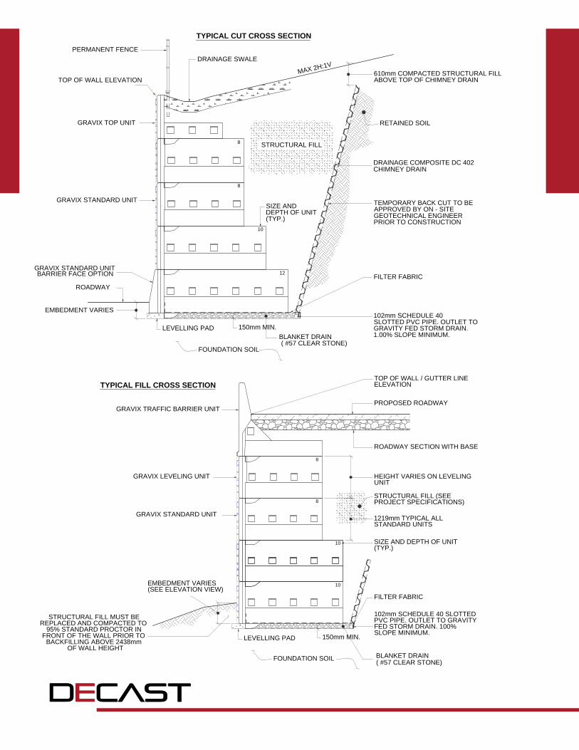
DECAST is now offering a new precast retaining wall system that reduces excavation requirements (typically 30% less than conventional RSS walls), uses native backfill instead of expensive granular, temporary shoring is not needed and steel straps or geogrid are not required. Additionally, there is a crash-tested, traffic barrier option that provides a finished retaining wall with the barrier in place.
TYPICAL CUT CROSS SECTION
TYPICAL FILL CROSS SECTION
GRAVIX TRAFFIC BARRIER UNIT
GRAVIX LEVELING UNIT
GRAVIX STANDARD UNIT
EMBEDMENT VARIES(SEE ELEVATION VIEW)
STRUCTURAL FILL MUST BEREPLACED AND COMPACTED TO
95% STANDARD PROCTOR INFRONT OF THE WALL PRIOR TO
BACKFILLING ABOVE 2438mmOF WALL HEIGHT
LEVELLING PAD
FOUNDATION SOIL
150mm MIN.
10
10
8
8
1219mm TYPICAL ALLSTANDARD UNITS
HEIGHT VARIES ON LEVELING
UNIT
ROADWAY SECTION WITH BASE
PROPOSED ROADWAY
TOP OF WALL / GUTTER LINEELEVATION
STRUCTURAL FILL (SEEPROJECT SPECIFICATIONS)
SIZE AND DEPTH OF UNIT(TYP.)
FILTER FABRIC
102mm SCHEDULE 40 SLOTTEDPVC PIPE. OUTLET TO GRAVITYFED STORM DRAIN. 100%SLOPE MINIMUM.
BLANKET DRAIN ( #57 CLEAR STONE)
12
10
8
8
610mm COMPACTED STRUCTURAL FILLABOVE TOP OF CHIMNEY DRAIN
DRAINAGE COMPOSITE DC 402CHIMNEY DRAIN
RETAINED SOIL
TEMPORARY BACK CUT TO BEAPPROVED BY ON - SITEGEOTECHNICAL ENGINEERPRIOR TO CONSTRUCTION
FILTER FABRIC
102mm SCHEDULE 40SLOTTED PVC PIPE. OUTLET TOGRAVITY FED STORM DRAIN.1.00% SLOPE MINIMUM.
LEVELLING PAD
FOUNDATION SOIL
150mm MIN.BLANKET DRAIN ( #57 CLEAR STONE)
EMBEDMENT VARIES
ROADWAY
GRAVIX STANDARD UNITBARRIER FACE OPTION
GRAVIX STANDARD UNIT
GRAVIX TOP UNIT
TOP OF WALL ELEVATION
PERMANENT FENCEDRAINAGE SWALE
SIZE ANDDEPTH OF UNIT(TYP.)
MAX 2H:1V
STRUCTURAL FILL
decastltd.com
A PRECAST CONCRETE RETAINING WALL SYSTEM DESIGNED TO MEET DEMAND FOR MINIMALEXCAVATION REQUIREMENTS
• Wall Face 1.22m x 2.44m (4′ x 8′)
• Wall Height 1.22m to 12.20m (4′ to 40′)
• Stem Length 1.83m to 6.10m (6′ to 20′)
• Traffic Barrier 0.91m or 1.07m (3′ or 3.5’)
decastltd.com
GRAVIX®
PRECAST WALL SYSTEM
DECAST is now offering a new precast retaining wall system that reduces excavation requirements (typically 30% less than conventional RSS walls), uses native backfill instead of expensive granular, temporary shoring is not needed and steel straps or geogrid are not required. Additionally, there is a crash-tested, traffic barrier option that provides a finished retaining wall with the barrier in place.
TYPICAL CUT CROSS SECTION
TYPICAL FILL CROSS SECTION
GRAVIX TRAFFIC BARRIER UNIT
GRAVIX LEVELING UNIT
GRAVIX STANDARD UNIT
EMBEDMENT VARIES(SEE ELEVATION VIEW)
STRUCTURAL FILL MUST BEREPLACED AND COMPACTED TO
95% STANDARD PROCTOR INFRONT OF THE WALL PRIOR TO
BACKFILLING ABOVE 2438mmOF WALL HEIGHT
LEVELLING PAD
FOUNDATION SOIL
150mm MIN.
10
10
8
8
1219mm TYPICAL ALLSTANDARD UNITS
HEIGHT VARIES ON LEVELING
UNIT
ROADWAY SECTION WITH BASE
PROPOSED ROADWAY
TOP OF WALL / GUTTER LINEELEVATION
STRUCTURAL FILL (SEEPROJECT SPECIFICATIONS)
SIZE AND DEPTH OF UNIT(TYP.)
FILTER FABRIC
102mm SCHEDULE 40 SLOTTEDPVC PIPE. OUTLET TO GRAVITYFED STORM DRAIN. 100%SLOPE MINIMUM.
BLANKET DRAIN ( #57 CLEAR STONE)
12
10
8
8
610mm COMPACTED STRUCTURAL FILLABOVE TOP OF CHIMNEY DRAIN
DRAINAGE COMPOSITE DC 402CHIMNEY DRAIN
RETAINED SOIL
TEMPORARY BACK CUT TO BEAPPROVED BY ON - SITEGEOTECHNICAL ENGINEERPRIOR TO CONSTRUCTION
FILTER FABRIC
102mm SCHEDULE 40SLOTTED PVC PIPE. OUTLET TOGRAVITY FED STORM DRAIN.1.00% SLOPE MINIMUM.
LEVELLING PAD
FOUNDATION SOIL
150mm MIN.BLANKET DRAIN ( #57 CLEAR STONE)
EMBEDMENT VARIES
ROADWAY
GRAVIX STANDARD UNITBARRIER FACE OPTION
GRAVIX STANDARD UNIT
GRAVIX TOP UNIT
TOP OF WALL ELEVATION
PERMANENT FENCEDRAINAGE SWALE
SIZE ANDDEPTH OF UNIT(TYP.)
MAX 2H:1V
STRUCTURAL FILL

decastltd.com
BOX MAINTENANCE HOLES
INSIDEDIMENSIONS
(mm)
MAX. STRAIGHT PIPE SIZE
- LONG WALL(mm)
MAX. STRAIGHT PIPE SIZE
- SHORT WALL(mm)
MAX. RIGHT ANGLE PIPE SIZE
- LONG WALL (mm)
MAX. RIGHT ANGLE PIPE SIZE - SHORT WALL
(mm)
MAX. STRAIGHT OPSS BOX CULVERT
- LONG WALL(mm)
MAX. STRAIGHT OPSS BOX CULVERT
- SHORT WALL (mm)
1200x1200 825 DIA. 825 DIA. 375 DIA. 375 DIA. N/A N/A
900x1800 1350 DIA. 525 DIA. 750 DIA. 200 DIA. N/A N/A
1500x1800 1350 DIA. 1050 DIA. 750 DIA. 525 DIA. N/A N/A
1800x2400 1800 DIA. 1350 DIA. 1050 DIA. 750 DIA. 1800x1200 N/A
2400x2400 1800 DIA. 1800 DIA. 1050 DIA. 1050 DIA. 1800x1200 1800x1200
1800x3000 2250 DIA. 1350 DIA. 1500 DIA. 750 DIA. 2400x1800 N/A
2400x3000 2250 DIA. 1800 DIA. 1500 DIA. 1050 DIA. 2400x1800 1800x1200
3000x3000 2250 DIA. 2250 DIA. 1500 DIA. 1500 DIA. 2400x1800 2400x1800
2400x3800 3000 DIA. 1800 DIA. 1950 DIA. 1050 DIA. 3000x2400 1800x1200
3000x3800 3000 DIA. 2250 DIA. 1950 DIA. 1500 DIA. 3000x2400 2400x1800
3000x4400 3000 DIA. 3000 DIA. 2250 DIA. 1500 DIA. 3000x2400 2400x1800
3000x5000 3000 DIA. 3000 DIA. 2550 DIA. 1500 DIA. 3000x2400 2400x1800
INSIDE DIMENSIONS
(mm)
WALL THICKNESS
(mm)
SLAB THICKNESS
(mm)
1200x1200 225 225
900x1800 225 225
1500x1800 225 225
1800x2400 225 / 250 225 / 300
2400x2400 225 / 250 300
1800x3000 225 / 250 300
2400x3000 225 / 250 300
3000x3000 225 / 250 300
2400x3800 250 300
3000x3800 250 300
3000x4400 250 300
3000x5000 250 300
APPLICATIONS
• Used when pipe diameters to be inserted are too large for a round maintenance hole
• Can be used as pumping stations, control structures and wet wells
DIMENSIONS
• 900mm x 1800mm to 3000mm x 5000mm• Walls are 225mm minimum• Base and top are 225mm minimum
ADDITIONAL INFORMATION
• Joints are sealed with butyl mastic sealant• For other sizes and/or depths greater than
7m, contact [email protected]
decastltd.com
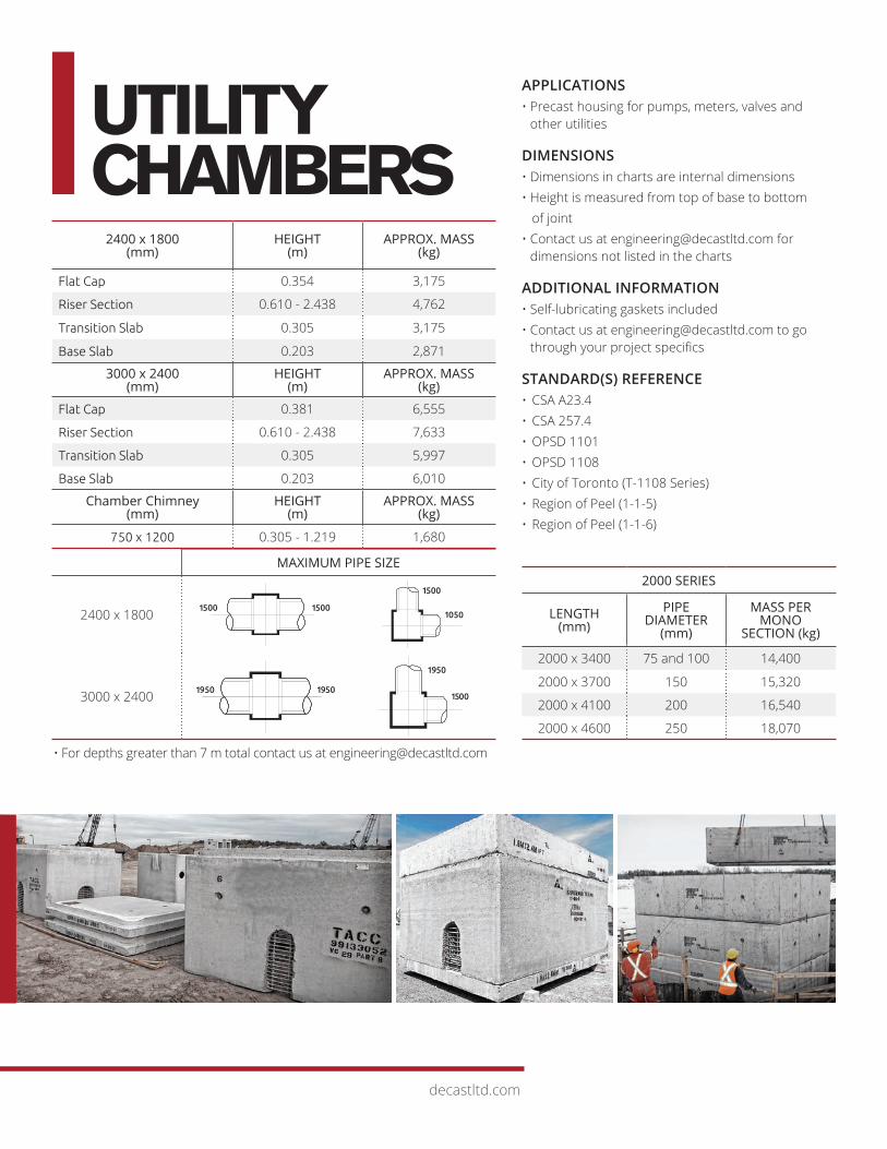
UTILITY CHAMBERS
ENGINEEREDPRECAST SOLUTIONSOur engineering team can work with you to design the exact precast concrete products you need to achieve your project objectives.
With DECAST you get higher quality, long asset life and leading engineered precast solutions.
2000 SERIES
LENGTH (mm)
PIPE DIAMETER
(mm)
MASS PER MONO
SECTION (kg)
2000 x 3400 75 and 100 14,400
2000 x 3700 150 15,320
2000 x 4100 200 16,540
2000 x 4600 250 18,070
MAXIMUM PIPE SIZE
2400 x 1800
3000 x 2400
2400 x 1800 (mm)
HEIGHT (m)
APPROX. MASS (kg)
Flat Cap 0.354 3,175
Riser Section 0.610 - 2.438 4,762
Transition Slab 0.305 3,175
Base Slab 0.203 2,871
3000 x 2400 (mm)
HEIGHT (m)
APPROX. MASS (kg)
Flat Cap 0.381 6,555
Riser Section 0.610 - 2.438 7,633
Transition Slab 0.305 5,997
Base Slab 0.203 6,010
Chamber Chimney(mm)
HEIGHT (m)
APPROX. MASS (kg)
750 x 1200 0.305 - 1.219 1,680
• For depths greater than 7 m total contact us at [email protected]
1500
1950 1950
1500
1500
1950
1050
1500
APPLICATIONS• Precast housing for pumps, meters, valves and
other utilities
DIMENSIONS• Dimensions in charts are internal dimensions• Height is measured from top of base to bottom of joint• Contact us at [email protected] for
dimensions not listed in the charts
ADDITIONAL INFORMATION• Self-lubricating gaskets included• Contact us at [email protected] to go
through your project specifi cs
STANDARD(S) REFERENCE• CSA A23.4• CSA 257.4• OPSD 1101• OPSD 1108• City of Toronto (T-1108 Series)• Region of Peel (1-1-5)• Region of Peel (1-1-6)

decastltd.com
UTILITY CHAMBERS
ENGINEEREDPRECAST SOLUTIONSOur engineering team can work with you to design the exact precast concrete products you need to achieve your project objectives.
With DECAST you get higher quality, long asset life and leading engineered precast solutions.
2000 SERIES
LENGTH (mm)
PIPE DIAMETER
(mm)
MASS PER MONO
SECTION (kg)
2000 x 3400 75 and 100 14,400
2000 x 3700 150 15,320
2000 x 4100 200 16,540
2000 x 4600 250 18,070
MAXIMUM PIPE SIZE
2400 x 1800
3000 x 2400
2400 x 1800 (mm)
HEIGHT (m)
APPROX. MASS (kg)
Flat Cap 0.354 3,175
Riser Section 0.610 - 2.438 4,762
Transition Slab 0.305 3,175
Base Slab 0.203 2,871
3000 x 2400 (mm)
HEIGHT (m)
APPROX. MASS (kg)
Flat Cap 0.381 6,555
Riser Section 0.610 - 2.438 7,633
Transition Slab 0.305 5,997
Base Slab 0.203 6,010
Chamber Chimney(mm)
HEIGHT (m)
APPROX. MASS (kg)
750 x 1200 0.305 - 1.219 1,680
• For depths greater than 7 m total contact us at [email protected]
1500
1950 1950
1500
1500
1950
1050
1500
APPLICATIONS• Precast housing for pumps, meters, valves and
other utilities
DIMENSIONS• Dimensions in charts are internal dimensions• Height is measured from top of base to bottom of joint• Contact us at [email protected] for
dimensions not listed in the charts
ADDITIONAL INFORMATION• Self-lubricating gaskets included• Contact us at [email protected] to go
through your project specifi cs
STANDARD(S) REFERENCE• CSA A23.4• CSA 257.4• OPSD 1101• OPSD 1108• City of Toronto (T-1108 Series)• Region of Peel (1-1-5)• Region of Peel (1-1-6)

decastltd.comdecastltd.com
WEB www.decastltd.com4
CONTACT Rob Micieli 416.605.7374 Vice President, Sales
David Archer, P.Eng. 705.715.1269 Manager, Engineering &Business Development
Mauro DeFranco, P.Eng.
647.500.3789 Technical Sales Engineer
Frank Mazza, C.E.T.
416.520.2779
John Pozzobon, C.E.T.
905.302.1062
Martin Fischer 705.796.8868
Jenny Ogden 705.734.2892ext 2240Manager, Shipping
Sales
Sales
Sales
SALES [email protected]
ENGINEERING
INFO & INQUIRIES
DECAST Ltd.8807 County Road 56Utopia, ON L0M 1T01.800.461.5632705.734.2892
! %
0


![Outback Sleepers Product Brochure Final[2] · Outback Sleepers offer the highest quality concrete retaining wall sleepers and precast panels, engineered to achieve wall heights in](https://static.cupdf.com/doc/110x72/5e8fc5dc543b38593c3f803b/outback-sleepers-product-brochure-final2-outback-sleepers-offer-the-highest-quality.jpg)