PRODUCTION SYSTEMS
CTU System
MAINTENANCE MANUAL

2 2
Binar Production Systems – CTU Maintenance
2019-04-11 ver 1.02 eng
Binar Elektronik AB
Visit/Delivery: Hedekullevägen 24, SE-461 38 Trollhättan
Post: Box 2001, 461 11 Trollhättan
Tel +46-(0)520-47 32 00 • www.binarelektronik.se • [email protected]
This document is copy protected and all rights belong to Binar Elektronik AB. This document may not, in whole or in part, be copied, photocopied or translated
without Binar AB's written consent. This document contains copyright information and may not be used or communicated to third parties without the prior written consent of Binar Elektronik AB.
3 3
Table of Contents
1. Introduction and system overview ................................. 4 1.1 Introduction ................................................................ 4
1.1.1 Prepared for the future ........................................ 4 1.2 Components ................................................................ 4
1.2.1 CTU ................................................................... 5 1.2.2 HAU ................................................................... 5 1.2.3 Standard cables .................................................. 6 1.2.4 Specific cables .................................................... 6
1.3 Overview .................................................................... 7
2. Fault processing ............................................................. 9
3. Trouble shooting tree ................................................... 10 3.1 NO LED indication on CTU ......................................... 10 3.2 CTU Bus error ............................................................ 11 3.3 Test cable indication problem ...................................... 12 3.4 Test Failed ................................................................ 13
4. Preventive maintenance ............................................... 14 4.1 CTU .......................................................................... 14 4.2 HAU ......................................................................... 14 4.3 Standard cables ......................................................... 14 4.4 Test cables ................................................................ 14
4.4.1 Switch probe .................................................... 14 4.4.2 Hocking system ................................................. 14 4.4.3 Cable gland ...................................................... 14 4.4.4 Spring probe ..................................................... 15 4.4.5 LED ................................................................. 26
5. Repairing ...................................................................... 26 5.1 Changing test cable .................................................... 26
5.1.1 Disassembling and repair ................................... 26 5.1.2 Root cause analyze ............................................ 26
5.2 Changing CTU ............................................................ 26 5.2.1 CAN ................................................................. 26 5.2.2 Profinet ............................................................ 26
5.3 Changing HAU ........................................................... 27 5.4 Changing X-CONN-card ............................................... 28
6. Data and spare parts .................................................... 29 6.1 Technical data ........................................................... 29 6.2 Dimensions ............................................................... 29
6.2.1 CTU Dimensions .............................................. 29 6.2.2 HAU Dimensions ................................................ 29
6.3 Certifications ............................................................. 30 6.3.1 CTU ................................................................. 30 6.3.2 HAU ................................................................. 31
4
4
1. Introduction and system overview
1.1 Introduction
The CTU system is used to perform component connection tests to preassembled car parts. The test objective is
to find assembly errors before the parts are assembled in the car. In order to manufacture at low cost, it is very
important to keep high quality throughout the whole process and not only assure quality at the EOL, but also at
every workstation where assembly is done.
In a modern car, there are a lot of electrical consumers like LEDs, speakers, sensors, switches, outlets and so
on. Those components are assembled onto parts like seats, interior door panels, interior roofs, bumpers and
cockpits. If one of those sensors, switches etc. is not functioning when the car is checked at the EOL, there is
often a major cost to correct it.
The LP335 CTU, Connection Test Unit, is a module that has a standardized electrical interface that may be used
to quality assure assembly of electrical harness. The most common method is to power up the components that
has been connected to the harness and measure the current consumption. The system can also measure the
impedance. For the more intelligent modules connected to the harness, there are three communication chan-
nels; CAN, LIN and Serial (RS232), that can be used. Those channels require a specific driver to be developed
for each case.
To be able to connect to each harness, a specific cable adapter must be manufactured. LP335 CTU includes in-
and outputs to control LEDs and read a switch in the adaptor. The LEDs can be lit up in the colors green, yellow
and red. They will show status to the operator during the test sequence. A switch inside the adaptor is used to
verify that the adaptor has been connected to the test harness.
1.1.1 Prepared for the future
The CTU is based on a PCB that is developed together with Volvo Car Tooling. The board contains several fea-
tures that is used in other equipment sold to Volvo Car. The latest is a new M12 Ethernet port included for fu-
ture internal service, WEB page for status monitoring and more.
1.2 Components
The components in a CTU system is.
- CTU
- HAU
- Standard cables
- Special cables
5
5
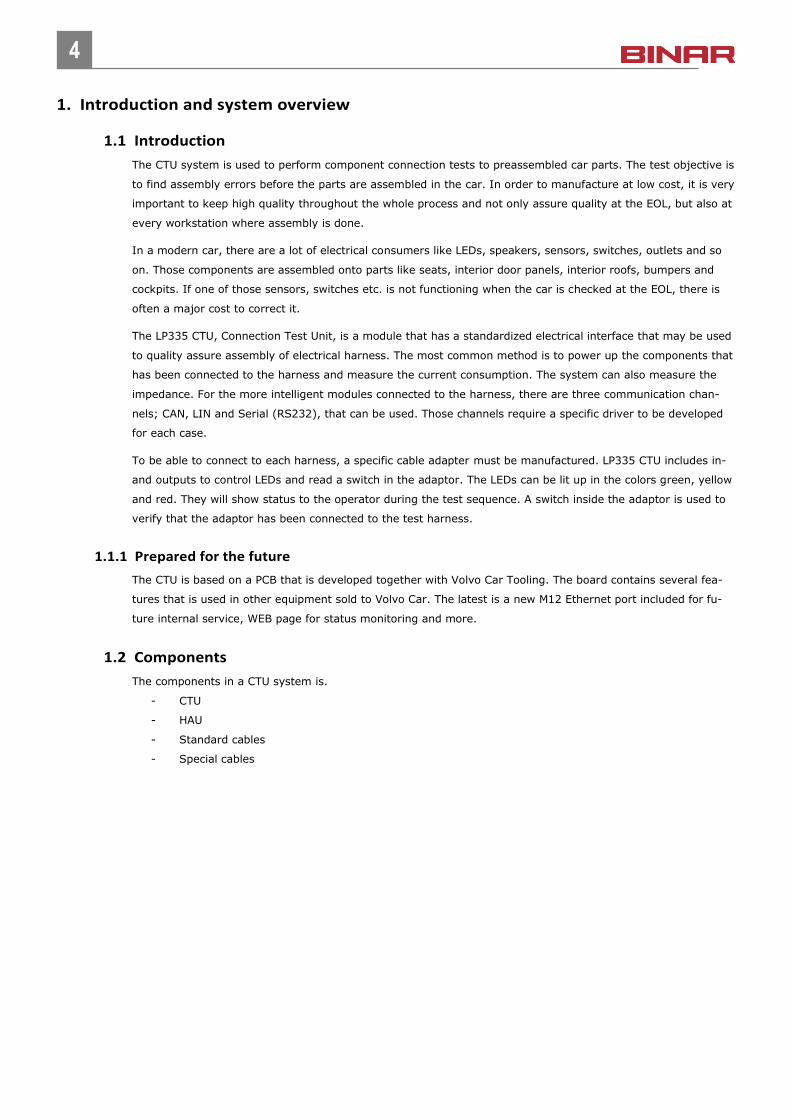
1.2.1 CTU
The main part of the CTU System is the CTU. The CTU is connected to the factory network and is acting like an
intelligent I/O-node. The interface is either CAN or ProfiNet.
Picture: LP335 – CTU (Connection test unit)
The CTU has 8 connectors at the bottom intended for connection of test objects. In the current version of the
CTU only connector 1 to 4 is implemented, Connector 5 to 8 is intended for future usage to communicate with
test objects.
In addition, there is one power connector and two bus connectors to connect to the factory network.
In most installations it is not enough with one CTU. When several CTUs is needed or when special cross connec-
tions are required a HAU is used.
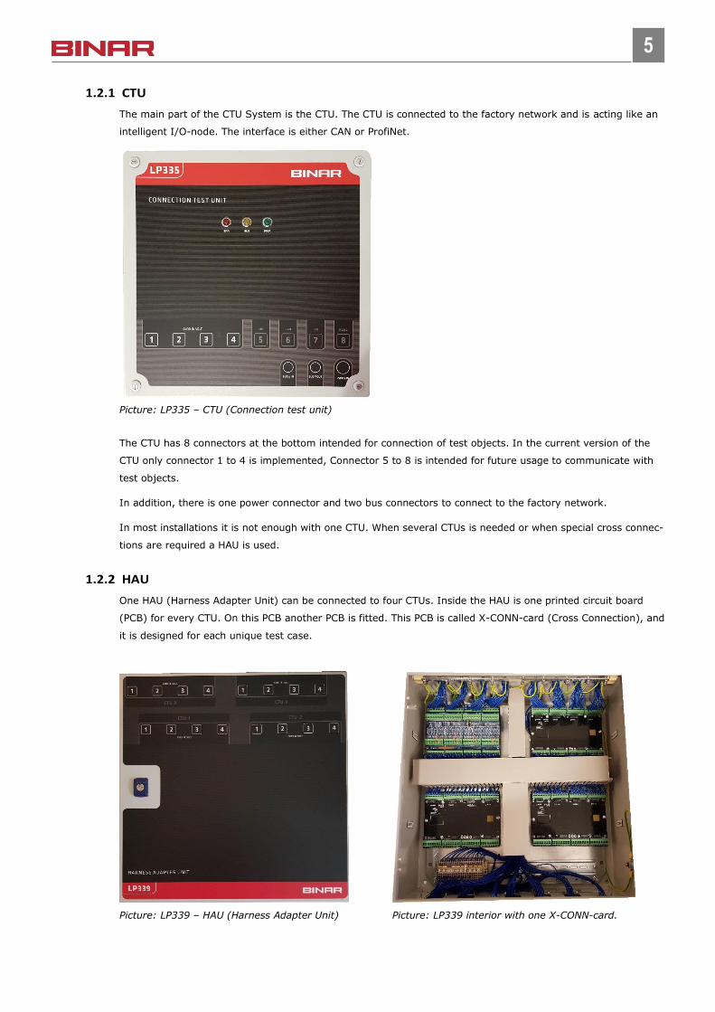
1.2.2 HAU
One HAU (Harness Adapter Unit) can be connected to four CTUs. Inside the HAU is one printed circuit board
(PCB) for every CTU. On this PCB another PCB is fitted. This PCB is called X-CONN-card (Cross Connection), and
it is designed for each unique test case.
Picture: LP339 – HAU (Harness Adapter Unit) Picture: LP339 interior with one X-CONN-card.
6
6
At the bottom of the HAU connectors for the specific cables are mounted. The gland plate is not a standard
part, it is made unique for every test case.
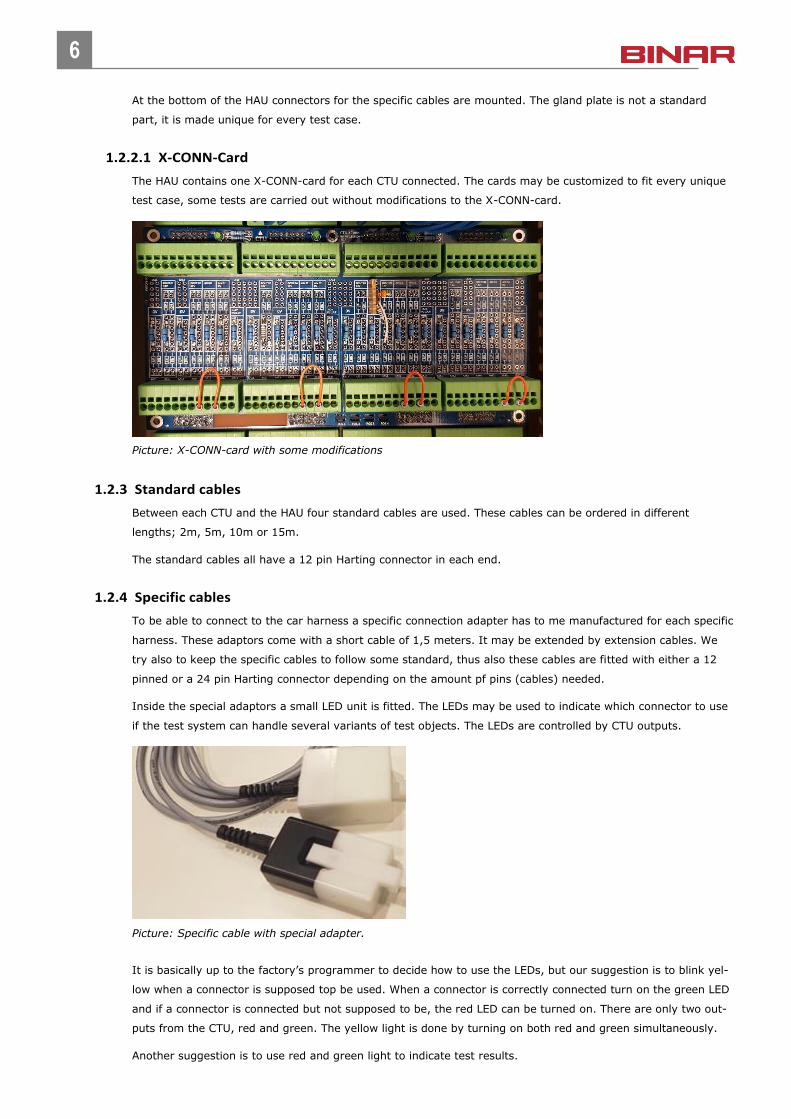
1.2.2.1 X-CONN-Card
The HAU contains one X-CONN-card for each CTU connected. The cards may be customized to fit every unique
test case, some tests are carried out without modifications to the X-CONN-card.
Picture: X-CONN-card with some modifications
1.2.3 Standard cables
Between each CTU and the HAU four standard cables are used. These cables can be ordered in different
lengths; 2m, 5m, 10m or 15m.
The standard cables all have a 12 pin Harting connector in each end.
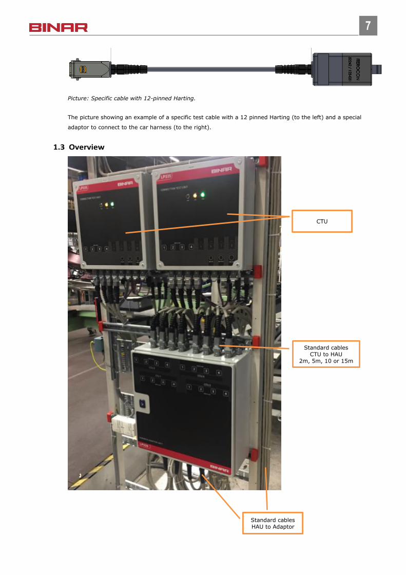
1.2.4 Specific cables
To be able to connect to the car harness a specific connection adapter has to me manufactured for each specific
harness. These adaptors come with a short cable of 1,5 meters. It may be extended by extension cables. We
try also to keep the specific cables to follow some standard, thus also these cables are fitted with either a 12
pinned or a 24 pin Harting connector depending on the amount pf pins (cables) needed.
Inside the special adaptors a small LED unit is fitted. The LEDs may be used to indicate which connector to use
if the test system can handle several variants of test objects. The LEDs are controlled by CTU outputs.
Picture: Specific cable with special adapter.
It is basically up to the factory’s programmer to decide how to use the LEDs, but our suggestion is to blink yel-
low when a connector is supposed top be used. When a connector is correctly connected turn on the green LED
and if a connector is connected but not supposed to be, the red LED can be turned on. There are only two out-
puts from the CTU, red and green. The yellow light is done by turning on both red and green simultaneously.
Another suggestion is to use red and green light to indicate test results.
7
7
Picture: Specific cable with 12-pinned Harting.
The picture showing an example of a specific test cable with a 12 pinned Harting (to the left) and a special
adaptor to connect to the car harness (to the right).
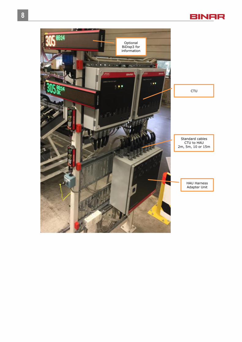
1.3 Overview
Standard cables
Standard cables CTU to HAU
2m, 5m, 10 or 15m
CTU
Standard cables HAU to Adaptor
CTU
8
8
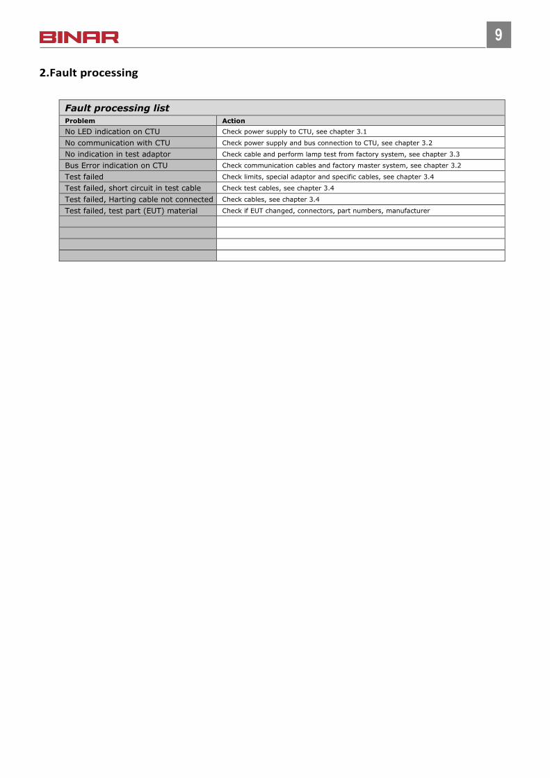
Standard cables CTU to HAU
2m, 5m, 10 or 15m
HAU Harness Adapter Unit
Optional BiDisp3 for information
CTU
9
9
2.Fault processing
Fault processing list
Problem Action
No LED indication on CTU Check power supply to CTU, see chapter 3.1
No communication with CTU Check power supply and bus connection to CTU, see chapter 3.2
No indication in test adaptor Check cable and perform lamp test from factory system, see chapter 3.3
Bus Error indication on CTU Check communication cables and factory master system, see chapter 3.2
Test failed Check limits, special adaptor and specific cables, see chapter 3.4
Test failed, short circuit in test cable Check test cables, see chapter 3.4
Test failed, Harting cable not connected Check cables, see chapter 3.4
Test failed, test part (EUT) material Check if EUT changed, connectors, part numbers, manufacturer
10
10
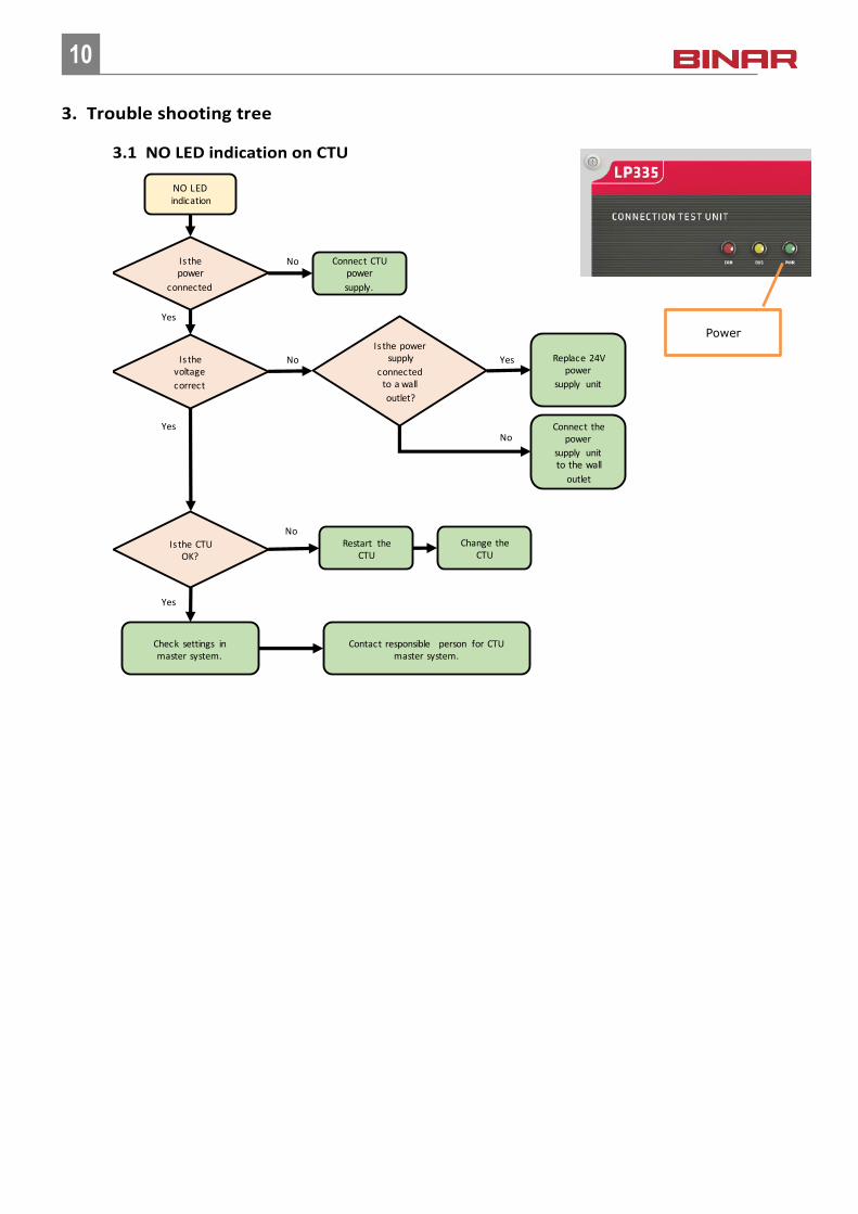
3. Trouble shooting tree
3.1 NO LED indication on CTU
Is the power
connected
NO LED indication
Yes
No Connect CTU power
supply.
Is the CTU OK?
No
Yes
Is the voltage
correct
No
Yes
Check settings in master system.
Contact responsible person for CTU master system.
Replace 24V power
supply unit
Restart the CTU
Change the CTU
Is the power supply
connected to a wall
outlet?
Yes
Connect the power
supply unit to the wall
outlet
No
Power
11
11
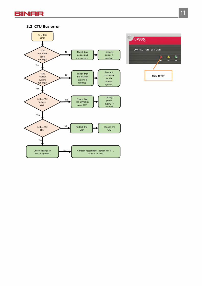
3.2 CTU Bus error
Is the communic
ation running?
CTU Bus Error
Yes
No Check bus cables and
connectors.
Yes
No Check that the 24VDC is
over 21V.
Is the CTU Voltage
OK?
Is the CTU OK?
No
Yes
No
Is the master
system running?
NoCheck that the master
system is running.
Yes
Check settings in master system.
Change cables if
needed.
Contact responsible person for CTU master system.
Contact reasonable
for the master
system.
Restart the CTU
Change power
supply if needed.
Change the CTU
Bus Error
12
12
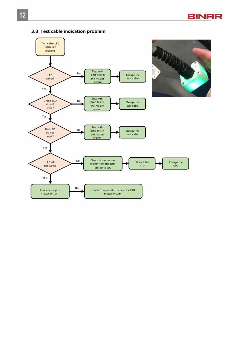
3.3 Test cable indication problem
LED works?
Test cable LED indication
problem
Yes
NoTest with
lamp test in
the master system
Yes
NoRed LED do not
work?
LED still not work?
No
Yes
No
Green LED do not
work?
No
Yes
Check settings in master system.
Contact responsible person for CTU master system.
Change the CTU
Change the test cable
Test with lamp test in
the master system
Change the test cable
Test with lamp test in
the master system
Change the test cable
Check in the master system that the right
out put is set.
Restart the CTU
13
13
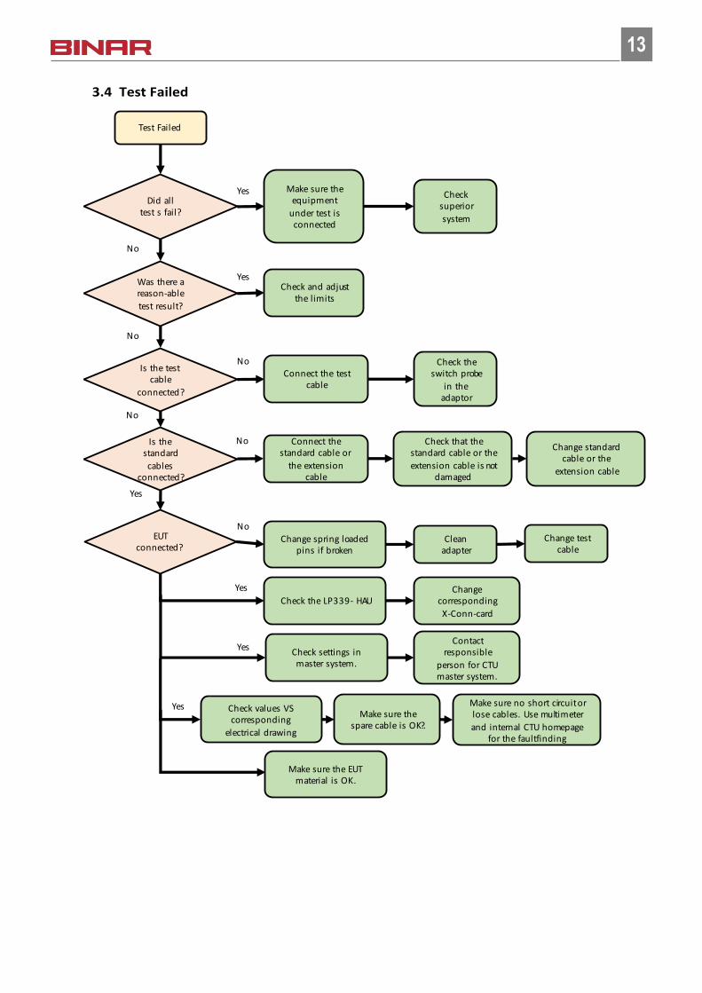
3.4 Test Failed
Did all test s fail?
Test Failed
No
Yes Make sure the equipment
under test is connected
Yes
NoIs the test
cable
connected?
EUT connected?
No
Yes
Was there a reason-able
test result?
Yes
No
Check settings in master system.
Contact responsible
person for CTU master system.
Change test cable
Check superior
system
Check and adjust the limits
Connect the test cable
Check the switch probe
in the adaptor
Change spring loaded pins if broken
Clean adapter
Change corresponding
X-Conn-card
Check the LP339 - HAU
Yes
Check values VS corresponding
electrical drawing
Make sure the spare cable is OK?.
Yes Make sure no short circuit or lose cables. Use multimeter
and internal CTU homepage for the faultfinding
Make sure the EUT material is OK.
NoIs the standard
cables connected?
No
Connect the standard cable or
the extension cable
Check that the standard cable or the
extension cable is not damaged
Change standard cable or the
extension cable
14
14
4. Preventive maintenance
4.1 CTU
Make sure all connectors are firmly connected and that the box is clean and closed. Also check for damages. If
the box is damaged it should be replaced or at least verified to have its full function before further usage.
4.2 HAU
Make sure all connectors are firmly connected and that the box is clean and closed. Also check for damages. If
the box is damaged it should be replaced or at least verified to have its full function before further usage.
If the HAU has been in transport or moved in any way, make sure to open it and verify that all X-CONN-cards
are correctly fitted.
4.3 Standard cables
Make sure all connectors are firmly connected that no cables are damaged. Moving cables should be checked
more regular to avoid problem. Depending on how often the system is used the moving cables should be
changed minimum once per year.
4.4 Test cables
Make sure all connectors are firmly connected that no cables are damaged. Moving cables should be checked
more regular to avoid problem (weekly). Depending on how often the system is used the moving cables should
be changed minimum once per year and 6 months at 68 jph.
Make sure the special adaptor is not damaged in any way. The adaptors are a sensitive part in the CTU concept
and need special attention.
Pins can be broken if something is penetrating the connector when it’s not used, be aware about how its han-
dled, how it is hanging, how its removed and dropped by the operator when they use it.
The test cables included adaptors, switch probe, hocking, gland, LED, spring probes (pins) should be checked
weekly.
Clean all the parts with a vacuum cleaner and a fine soft brush, use no oil or cleaning chemicals!
4.4.1 Switch probe
Check the function of the switch probe by pressing it with a small tool, it should be moving in and out without
any hiccups.
4.4.2 Hocking system
Make sure the hocking system is clean and that its working correctly.
4.4.3 Cable gland
Check the cable gland so its tightened and not damaged and make sure the cable attached properly.
15
15
4.4.4 Spring probe
Check the spring probe (pins) as soon as needed but minimum once a week.
The spring probes is recommended to change every month if used daily at 68 jph.
If an adaptor is broken, send it to the supplier for repair.
There are 2 types of spring probes (probe with pin head and probe with a bowl head) and the approach to re-
move and to assemble the probes differs.
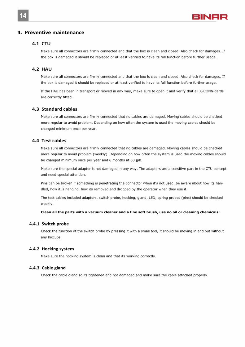
4.4.4.1 Probes removal (pin type)
Ensure you have a plier that is not too big and fits between the probes.
Grab the probe with pliers with firm pressure
16
16
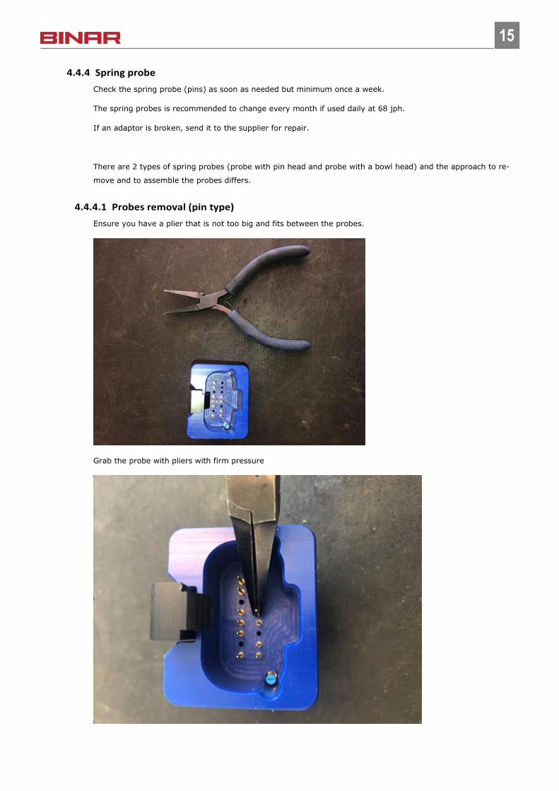
Pull out the probe straight upp, the socket will remain in the connector
4.4.4.2 Probes removal (bowl type)
Ensure you have screwdriver that will fit the cavity
17
17
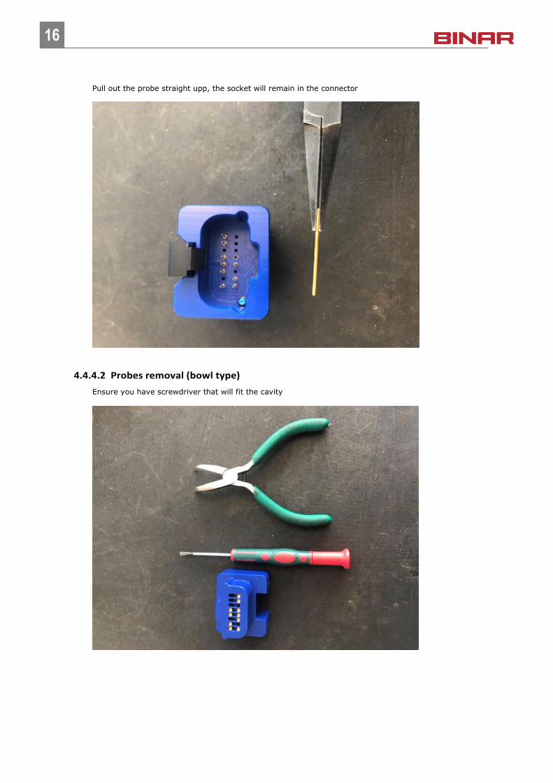
Insert the screwdriver in the cavity below the probe and support the screwdriver on the plastic to achieve lever
Now gently pusch down the screwdriver
18
18
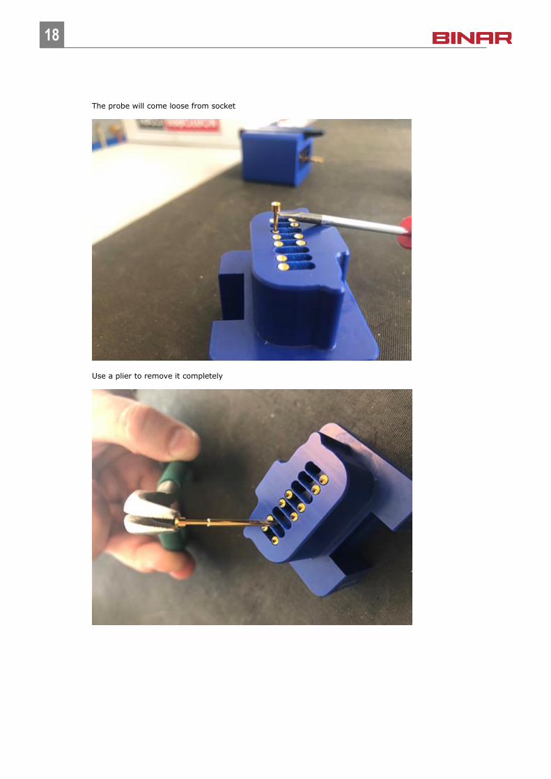
The probe will come loose from socket
Use a plier to remove it completely
19
19
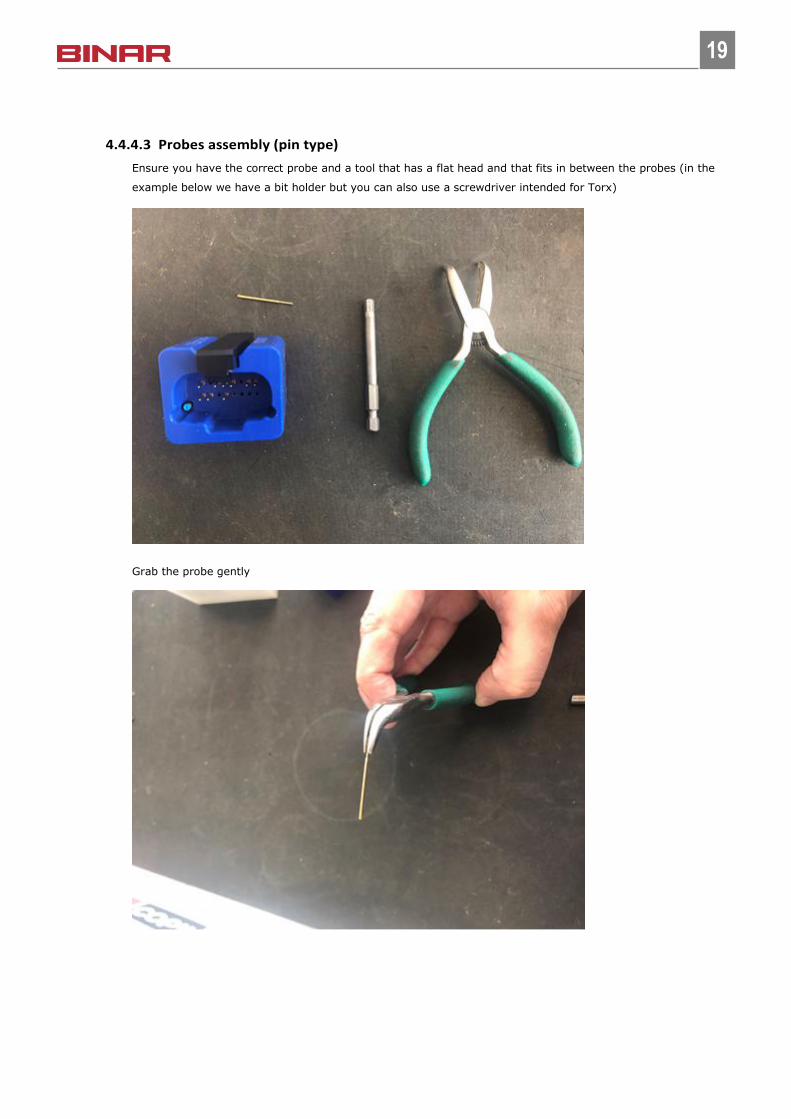
4.4.4.3 Probes assembly (pin type)
Ensure you have the correct probe and a tool that has a flat head and that fits in between the probes (in the
example below we have a bit holder but you can also use a screwdriver intended for Torx)
Grab the probe gently
20
20
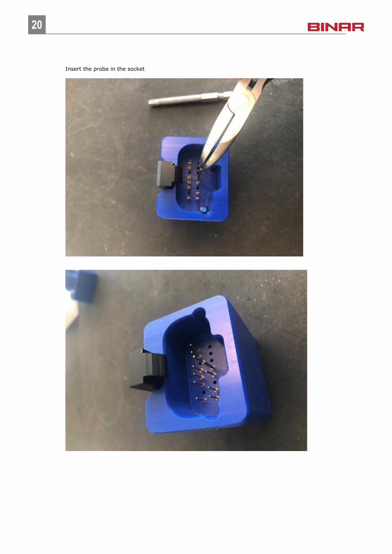
Insert the probe in the socket
21
21
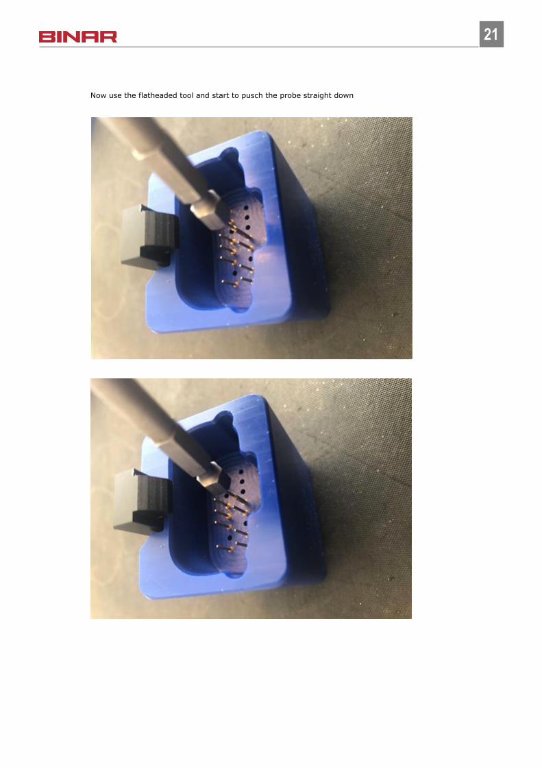
Now use the flatheaded tool and start to pusch the probe straight down
22
22
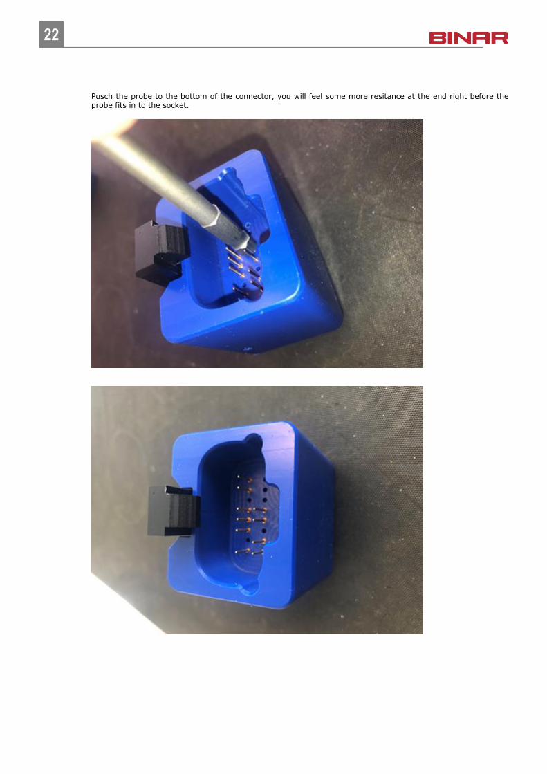
Pusch the probe to the bottom of the connector, you will feel some more resitance at the end right before the probe fits in to the socket.
23
23
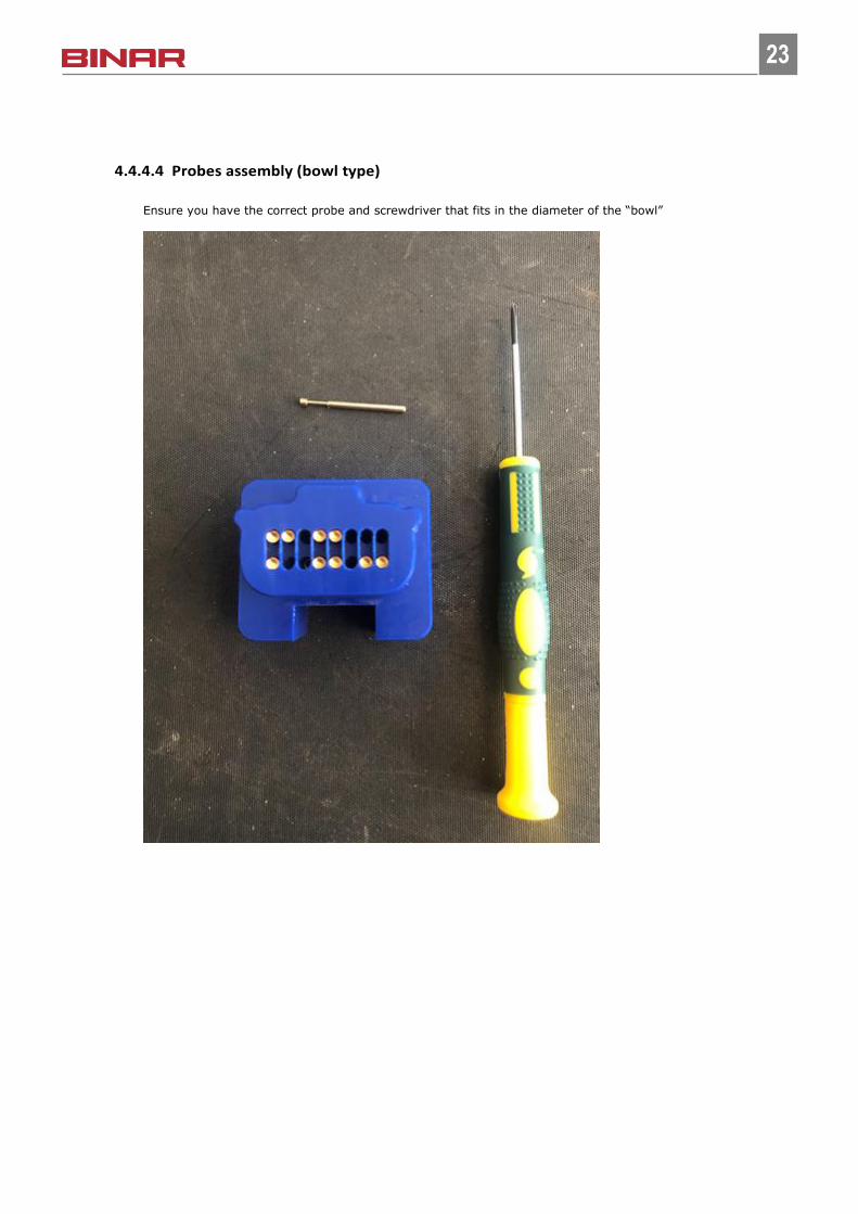
4.4.4.4 Probes assembly (bowl type)
Ensure you have the correct probe and screwdriver that fits in the diameter of the “bowl”
24
24
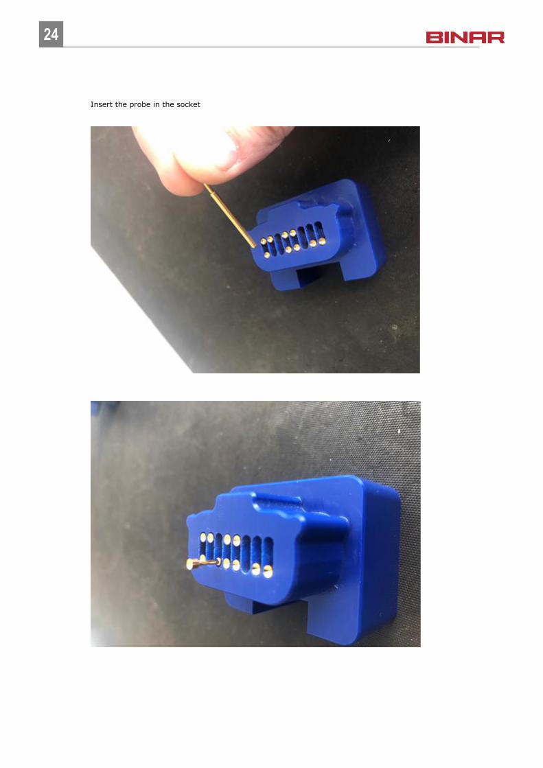
Insert the probe in the socket
25
25
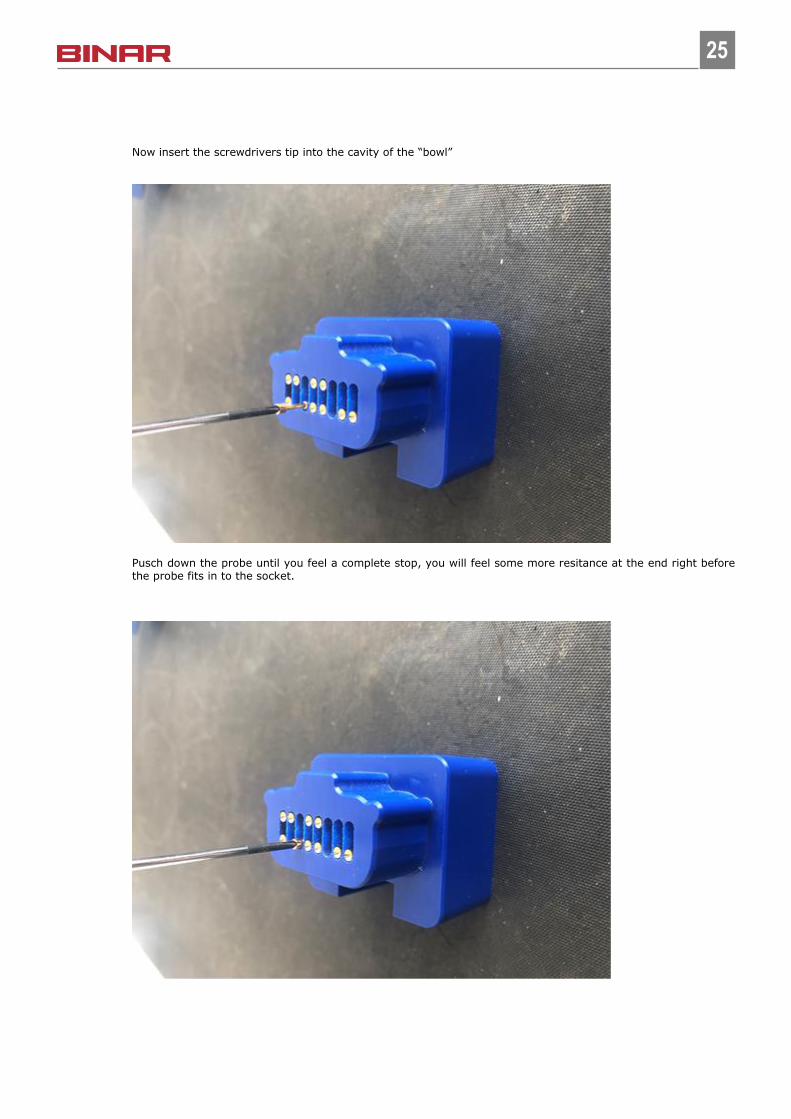
Now insert the screwdrivers tip into the cavity of the “bowl”
Pusch down the probe until you feel a complete stop, you will feel some more resitance at the end right before the probe fits in to the socket.
26
26
4.4.5 LED
Check that the LED is working properly.
5. Repairing
5.1 Changing test cable
Make sure the new cable has the same part number as the old one. Disconnect the old cable and connect the
new one the same way.
5.1.1 Disassembling and repair
Repairs should only be done by educated and skilled maintenance personal, to soldering inside the adaptors
should only be done by personal with soldering education and diploma. If the adapter is disassembled the guar-
antee ends for the test cable. We recommend that the cables is sent to the supplier for repair.
5.1.2 Root cause analyze
1. Was the cable removed before going to next station?
2. Do the process stop the line is operator forget to remove the test cable?
3. How does the process look like, do the operator remove the cable by releasing the hock properly?
4. No risk that the cable will hook in to something on the line?
5. Have someone disassembled the connector and not tightened the gland?
6. Was the cable gland loose when the problem was found?
7. How do the cables been mounted, can they hit something or each other when operator release them?
Take photos of the problem and send the broken cable to supplier.
5.2 Changing CTU
The CTUs come in two different versions depending on communication interface.
CAN variant part number 51335 LP335/CTU/C and have A-coded M12 connectors.
Profinet variant part number 52335 LP335/CTU/P and have D-coded M12 connectors.
5.2.1 CAN
To replace a CAN-version, change the MAC-address of the CTU in the superior communication system and re-
place the CTU.
Make sure to disconnect the power supply before disconnecting other cables and connect the power supply to
the new CTU after connecting all the other cables. While the CAN-cables are disconnected the CAN-nodes lo-
cated after this CTU on the CAN-bus will not communicate with the master.
5.2.2 Profinet
When replacing a ProfiNet version of a CTU, make sure it has the same “Device Name” as the old one and re-
place it. To change the CTU’s “Device Name” use for example Siemens tool “PRONETA”.

27
27
Make sure to disconnect the power supply before disconnecting other cables and connect the power supply to
the new CTU after connecting all the other cables. While the power supply to the CTU is disconnected the
ProfiNet communication will not go through the CTU.
5.3 Changing HAU
The HAU has no intelligence and no communication with any other device. To change a HAU simply replace it
with an identical one.
If the spare HAU is missing the gland plate, all wires from the bottom Harting connectors must be removed
from the base card in the HAU and the plate must be removed and installed in the new HAU. Also, the X-CONN-
cards must be moved to the new HAU, see next chapter.
28
28
5.4 Changing X-CONN-card
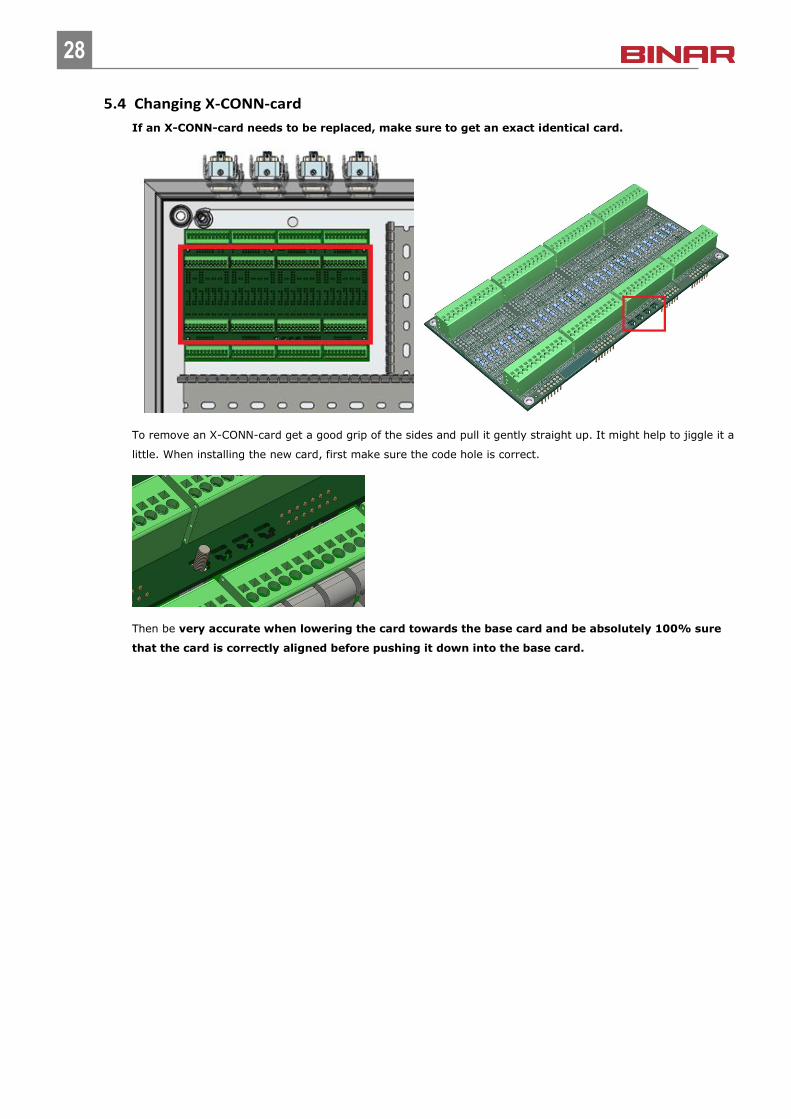
If an X-CONN-card needs to be replaced, make sure to get an exact identical card.
To remove an X-CONN-card get a good grip of the sides and pull it gently straight up. It might help to jiggle it a
little. When installing the new card, first make sure the code hole is correct.
Then be very accurate when lowering the card towards the base card and be absolutely 100% sure
that the card is correctly aligned before pushing it down into the base card.
29
29
6. Data and spare parts
6.1 Technical data
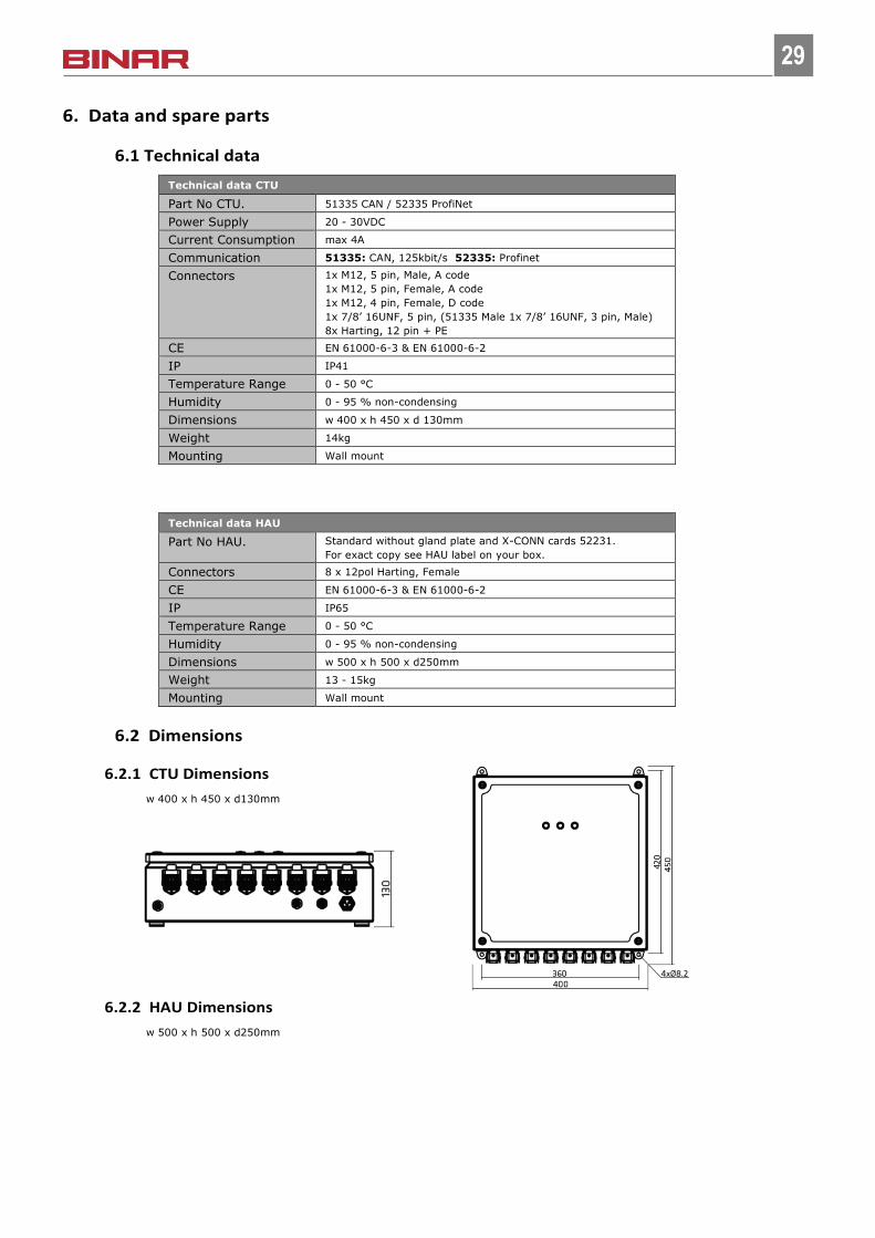
Technical data CTU
Part No CTU. 51335 CAN / 52335 ProfiNet
Power Supply 20 - 30VDC
Current Consumption max 4A
Communication 51335: CAN, 125kbit/s 52335: Profinet
Connectors 1x M12, 5 pin, Male, A code
1x M12, 5 pin, Female, A code
1x M12, 4 pin, Female, D code
1x 7/8’ 16UNF, 5 pin, (51335 Male 1x 7/8’ 16UNF, 3 pin, Male)
8x Harting, 12 pin + PE
CE EN 61000-6-3 & EN 61000-6-2
IP IP41
Temperature Range 0 - 50 °C
Humidity 0 - 95 % non-condensing
Dimensions w 400 x h 450 x d 130mm
Weight 14kg
Mounting Wall mount
Technical data HAU
Part No HAU. Standard without gland plate and X-CONN cards 52231.
For exact copy see HAU label on your box.
Connectors 8 x 12pol Harting, Female
CE EN 61000-6-3 & EN 61000-6-2
IP IP65
Temperature Range 0 - 50 °C
Humidity 0 - 95 % non-condensing
Dimensions w 500 x h 500 x d250mm
Weight 13 - 15kg
Mounting Wall mount
6.2 Dimensions
6.2.1 CTU Dimensions
w 400 x h 450 x d130mm
6.2.2 HAU Dimensions
w 500 x h 500 x d250mm
30
30
6.3 Certifications
6.3.1 CTU
31
31
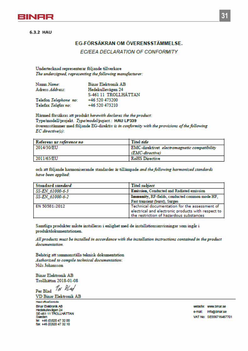
6.3.2 HAU