8/3/2019 Couplings of Micro Strip Square Open-loop Resonators for Cross-coupled Planar Microwave Filters
http://slidepdf.com/reader/full/couplings-of-micro-strip-square-open-loop-resonators-for-cross-coupled-planar 1/11
IEEE TRANSACTIONS ON MICROWAVE THBORY AN D TECHNIQUES, VOL 44, NO 12, DECEMBER 1996
~
2099
lings of Microstrip SquareII
Open-Loop Resonators tor
Cross-Coupled Planar Microwave FiltersJ i a - S h e n g H o n g , Member , IEEE, and M i c h a e l J. Lancas te r , Member, IEEE
Abstract- A new type of cross-coupled planar microwave
filter using coupled microstrip square open-loop 1,esonators is
proposed. A method for the rigorous calculation of the coupling
coefficients of three basic coupling structures encmountered in
this type of filters is developed. Simple empirical models are
derived for estimation of the coupling coefficients. Experiments
are performed to verify the theory. A four-pole elliptic function
filter of this type is designed and fabricated. Both the theoretical
and experimental performance is presented.
I. INTRODUCTION
ODERN microwav e comm unication systf ms require,M specially in satellite and mobile communications,
high-performance narrow-band bandpass filters having low
insertion loss and high selectivity together with linear phase
or flat group delay in the passband. According to the early
work on filter synthesis 111, it has been knowri that when
frequency selectivity and bandpass loss are cons:dered to be
the important filtering properties, then the optimum filters
are those exhibiting ripple in both passbands an d stopbands.
Such a filter response can be realized using filter5 with cross
couplings between nonadjacent resonators 121. 'These cross
couplings give a number of alternative paths which a signal
may take between the input and output ports. Depending
on the phasing of the signals, the multipath effect may
cause attenuation poles at finite frequencies or group delay
flattening, or even both simultaneously. Usually, the cross-
coupled resonator filters are realized u sing waveguide cavities
or dielectric resonator loaded cavities because of their low
loss. However, in order to reduce size, weight, and cost, there
has been a growing interest in planar structures [3]-[14].
The disadvantage of high conductor loss of the planar filters
using conventional conducting thin films can be cwercome by
replacing them with high-temperature superconducting (HTS)
thin films. These can have a very low conductor loss [3]-[6].
An alternative is by combining with active MMIC devices to
compensate the loss [141.One difficulty in realizing the cross-coupled microwave
filters in the planar structures is to identify and control the
required electric and magnetic couplings for the nonadjacent
Manuscript received April 18, 1996; revised July 22, 15'96. This work
was supported by the Engineering and Physical Sciences Research Council
(EPSRC), U.K.
The authors are with the School of Electronic and Electrical Engineering,University of Birmingham, Edgbaston, Birmingham B IS 2T7, U.K.
Publisher Item Identifier S 00 1 8-9480(96)07906-9.
P
Frght-pule
Fig. 1, Some cross-coupled planar microwave handpass filters comprised of
coupled microstrip square open-loop resonators on substrate (not shown) with
a relative dielectric constant E~ an d a thickness h.
resonators. Several new cross-coupled planar filter structures
have been proposed recently, including the microstrip dual-
mode filters [3], [9], the dual-plane multicouple line filters
[ I O ] and the microstrip square open-loop resonator filters
[13]. Shown in Fig. 1 are some typical cross-coupled planar
filters comprised of microstrip square open-loop resonators.
Comp ared with the microstrip dual-mode filters the microstrip
square open-loop resonator filters can have a smaller size. For
instance a four-pole dual-mode ring filter requires a circuit
size amounting to 2A,,/n- x & , I T , where A is the guided
wavelength at the midband frequency. Whilst the circuit size
for a four-pole open-loop resonator filter as shown in Fig. 1,
only amounts to A4 x X,,/4, giving more than 50% sizereduction. Compared with the dual-plane multicoupled line
filters, the microstrip open-loop resonator filters are much
simpler in structure, they require no grounding and coupling
apertures. It would also seem that the coupled square open-
loop resonators are more flexible to construct a variety of
cross-coupled planar filters which have the similar coupling
configurations as those of waveguide cavity cross-coupled
filters.
8/3/2019 Couplings of Micro Strip Square Open-loop Resonators for Cross-coupled Planar Microwave Filters
http://slidepdf.com/reader/full/couplings-of-micro-strip-square-open-loop-resonators-for-cross-coupled-planar 2/11
2100 IEEE TRANSACTIONS ON MICROWAVE THEORY AND TECHNIQUES, VOL. 44, NO . 12, DECEMBER 1996
a Y
a- +
(c )
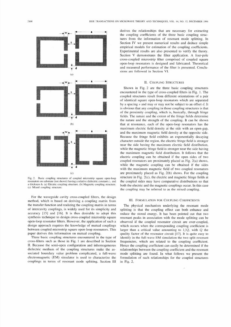
Fig. 2. Basic coupling structures of coupled microstrip square open-loop
resonators on substrate (not shown) having a relative dielectric constant E~ an da thickness h. (a) Electric coupling structure. (b) Magnetic coupling structure.(c) Mixed coupling structure.
For the waveguide cavity cross-coupled filters, the design
method, which is based on deriving a coupling matrix from
the transfer function and realizing the coupling matrix in terms
of intercavity couplings, is widely used for its simplicity and
accuracy [15] an d [16]. It is thus desirable to adopt this
synthesis technique to design cross-coupled microstrip square
open-loop resonator filters. However, the application of such adesign approach requires the know ledge of mutual couplings
between coupled microstrip square open-loop resonators. This
paper derives this information on mutual coupling.
Three basic coupling structures encountered in the type of
cross-filters such as those in Fig. 1 are described in Section
11. Because the semi-open configuration and inhomogeneous
dielectric medium of the coupling structures make the as-
sociated boundary value problem complicated, a full-wave
electromagnetic (EM) simulator is used to characterize the
couplings in terms of resonant mode splitting. Section I11
derives the relationships that are necessary for extracting
the coupling coefficients of the three basic coupling struc-
tures from the information of resonant mode splitting. In
Section IV we present numerical results and deduce simple
empirical models for estimation of the coupling coefficients.
Experimental results are also presented to verify the theory.
Section V demonstrates the filter application. A four-polecross-coupled microstrip filter comprised of coupled square
open-loop resonators is designed and fabricated. Theoretical
and measured performance of the filter is presented. Conclu-
sions are followed in Section VI.
11. COUPLINGTRUCTURES
Shown in Fig. 2 are the three basic coupling structures
encountered in the type of cross-coupled filters in Fig. 1. T h e
coupled structures result from different orientations of a pair
of identical square open-loop resonators which are separated
by a spacing s and may or m ay not be subject to an offset d. It
is obvious that any coup ling in those coupling structures is that
of the proximity coupling, which is, basically, through fringe
fields. The nature and the extent of the fringe fields determine
the nature and the strength of the coupling. It can be shown
that at resonance, each of the open-loop resonators has the
maximum electric field density at the side with an open-gap,
and the maximum magnetic field density at the opposite side.
Because the fringe field exhibits an exponentially decaying
character outside the region, the electric fringe field is stronger
near the side having the maximum electric field distribution,
while the m agnetic fringe field is stronger near the side having
the maximum magnetic field distribution. It follows that the
electric coupling can be obtained if the open sides of two
coupled resonators are proximately placed as Fig. 2(a) shows,
while the magnetic coupling can be obtained if the sideswith the maximum magnetic field of two coupled resonators
are proximately placed as Fig. 2(b) shows. For the coupling
structure in Fig. 2(c), the electric and magn etic fringe fields at
the coupled sides may have comparative distributions so that
both the electric and the magn etic coupling s occur. In this case
the coupling may be referred to as the mixed coupling.
111. FORMULATIONOR COUPLING COEFFICIENTS
The physical mechanism underlying the resonant mode
splitting is that the coupling effect can both enhance and
reduce the stored energy. It has been pointed out that two
resonant peaks in association with the mode splitting can be
observed if the coupled resonator circuit are over-coupled,
which occurs when the corresponding coupling coefficient is
larger than a critical value amounting to l / Q , with Q th e
quality factor of the resonator circuit [17]. It is quite easy to
identify in the full-wave EM simulation the two split resonant
frequencies, which are related to the coupling coefficient.
Hence the coupling coefficient can easily be determined if the
relationships between the coupling coefficient and the resonant
mode splitting are found. In what follows we present the
formulation of such relationships for the coupled structures
in Fig. 2.

8/3/2019 Couplings of Micro Strip Square Open-loop Resonators for Cross-coupled Planar Microwave Filters
http://slidepdf.com/reader/full/couplings-of-micro-strip-square-open-loop-resonators-for-cross-coupled-planar 3/11
HONG AND LANCASTER: COUPLINGS OF MICROSTRIP SQUARE OPEN-LOOP RESONATORS 2101
A . Electric Coupling
For the fundamental mode near its resonance, an equivalent
lumped-element circuit model for the coupling structure in
Fig. 2(a) is given in Fig. 3(a), where L an d C are the self-
inductance and self-capacitance so that (LC)- ' / ' equals the
angular resonant frequency of uncoupled resonators, and C,
represents the mutual capacitance. At this stage it should be
make clear that the coupled structure considered is inher-
ently distributed element so that the lumped-element circuit
equivalence is valid on a narrow-band basis, namely, near
its resonance as we have emphasized at the beginning. The
same comment is applicable for the other coupled structures
discussed later, Now, if we look into reference planes TI-Tian d T2 - Ti, we can see a two-port network which may be
described by the following set of equations
I1 =jwcv,- wc,v, ( 1 4
I2 =jwCV, - wC,Vl (1b)
in which a sinusoidal waveform is assumed. It might be well
to mention that ( la) and (lb) imply that the self-capacitanceC is the capacitance seen in one resonant loop of Fig. 3(a)
when the capacitanc e in the adjacent loop is shorted out. Thus,
the second terms on the right-hand side of ( la ) and (l b) are
the induced currents resulted from the increasing voltage in
resonant loop 2 and loop 1, respectively. From (la) and (Ib)
four Y parameters
y11 = y 2 2
Yl2 =El
= w c ( 2 4
= - J W C , (2b)
can easily be found by definitions.
According to the network theory [181 an alternz ive form ofthe equivalent circuit in Fig. 3(a) can be obtained and is shown
in Fig. 3(b). This form yields the same two-porl parameters
with those of the circuit of Fig. 3(a), but it is more con venient
for our discussions. Actually, it can be shown that the electric
coupling between the two resonant loop s is repreliented by an
admittance inverter J = wC,. If the symmetry plane T - T'
in Fig. 3(b) is replaced by a n electric wall (or a silort-circuit),
the resultant circuit has a resonant frequency
1
f e = 2 7 l 4 7 c T z J '( 3 )
This resonant frequency is lower than that of uncoupled
single resonator, which has also been confirmed by the full-
wave simulations. A physical explanation is that the coupling
effect enhances the capability of storing charge of the single
resonator when the electric wall is inserted in the symmetrical
plane of the coupled structure. Similarly, replacing the sym me-
try plane in Fig. 3(b) by a magnetic wall (or an open-circuit)results in a sin gle resonant circuit having a resonant frequency
1
= 2 n J m(4)
In this case the coup ling effect reduces the cap abill y of storing
charge so that the resonant frequency is increased.
y,, :T'i L _ _ _ - - - - - -' l T',
J=wC,(b)
Fig 3 (a) Equivalent circuit of the coupled open-loop resonators exhibitingthe electric coupling (b) An alternative form of the equivalent circuit with anadmittance inverter J = wC,,, to represent the coupling
Equations (3) and (4) can be used to find the electric
coupling coefficient IC E
(5)
which is identical with the definition of ratio of the coupled
electric energy to the stored energy of uncoupled singleresonator.
B. Magnetic Coupling
Shown in Fig. 4(a) is an equivalent lumped-element circuit
model for the coupling structure in Fig. 2(b) near its resonance,
where L an d C are the self-inductance and self-capacitance,
an d L , represents the mutual inductance. In this case the
coupling equations described the two-port network at reference
planes TI - Ti an d Tz - Ti ar e
VI =jwLI1 + wL,I2, ( 6 4
v,=jwLI, + jWLmII. (6b)
Equations (6a) and (6b) also imply that the self-inductanceL is the inductance seen in one resonant loop of Fig. 4(a)
when the adjacent loop is open-circuited. Thus, the second
terms on the right-hand side of (6a) and (6b) are the induced
voltage resulted from the increasing current in loops 2 an d
1, respectively. From (6a) and (6b) we can find four Z -
parameters

8/3/2019 Couplings of Micro Strip Square Open-loop Resonators for Cross-coupled Planar Microwave Filters
http://slidepdf.com/reader/full/couplings-of-micro-strip-square-open-loop-resonators-for-cross-coupled-planar 4/11
2102 IEEE TRANSACTIONS ON MICROWAVE THEORY AND TECHNIQUES, VOL. 44, NO. 12, DECEMBER 1996
Fig. 4. (a) Equivalent circuit of the coupled open-loop resonators exhibiting
the magnetic coupling. (b) An alternative form of the equivalent circuit withan impedance inverter K = wLh to represent the coupling.
Sho wn in Fig. 4(b) is an alternative fo rm of equivalent
circuits having the same network parameters as those of
Fig. 4 (a). Similarly, it can be shown that the magnetic cou pling
between the two resonant loops is represented by an impedance
inverter K = wL,. If the symmetry plane T -T' in Fig. 4(b)
is replaced by an electric wall (or a short-circuit), the resultant
single resonant circuit has a resonant frequency
It can be shown that the increase in resonant frequency,
which has also been observed in the full-wave simulations,
is because the coupling effect reduces the stored flux in the
single resonator circuit when the electric wall is inserted in
the symmetric plane. If the symmetry plane in Fig. 4(b) is
replaced by a magnetic wall (or an open-circuit), the resultant
single resonant circuit has a resonant frequency
1
.fm = 27rJ(L + L m ) C .(9)
In this case it turns out that the coupling effect increases the
stored flux so that the resonant frequency is shifted down.
Similarly, (8) an d (9) can be used to find the magnetic
coupling coefficient k~
It should be emphasized that the magnetic coupling coefficient
defined by (10) corresponds to the definition of ratio of the
coupled magnetic energy to the stored energy of uncoupled
single resonator. One might also notice that the magnetic
coupling defined by (10) and the electric coupling defined by
( 5 ) are in phase opposition. This type o f coupling is what we
really need for the realization of cross-coupled filters.
C. Mixed Coupling
For the coupling structure of Fig. 2(c), the electric and
magnetic field distributions on the coupled arms of two
resonators are comparative so that neither the electric coupling
nor the magnetic coupling can be ignored. Hence, in this case
the coupling may be referred to as the mixed coupling. For the
fundamental m ode of this coupling structure near its resonance,
a network representation is shown in Fig. 5(a). Notice that
the Y-parameters are the parameters of a two-port network
looked into the left of reference plane TI - Ti and the right
of reference plane T2 - Ti, hile the 2-parameters are the
parameters of the other two-port network looked into the right
of reference plane TI - T{ and the left of reference plane
T2 - Ti. The Y - and 2-parameters are defined by
y11 = y 2 2
y12 =Y21
21 1 = 2 2 2
21 2 =Z21
= w c ,
= w c k
= w L ,
= j w L L .
where C , L , C i , an d LA are the self-capacitance, the self-
inductance, the mutual capacitance, and the mutual inductanceof an associated equivalent lumped-element circuit shown in
Fig. 5(b). It should be explained that the minus sign assigned
to the mutual capacitance is based on tw o facts. The first
fact is that the electric and magnetic couplings enhance each
other (add in phase). The second fact is that when the
symmetry plane of the equivalent circuit is shorted-circuit,
which may correspond to the excitation for the currents on
the coupled arms of Fig. 2(c) having the same magnitude but
the opposite direction, the resonant frequency is higher than
that o f uncoupled single resonator. In Fig. 5(b), one can also
identify an impedance inverter K = w L i and a n admittance
inverter J = WCL hich represent the magnetic coupling and
By inserting an electric wall and a magnetic wall intothe symmetry plane of the equ ivalent circuit in Fig. 5(b),
respectively, we obtain
the electric coupling, respectively.
1f e =
27r2/(L- L L ) ( C- CL) '1
f m = 27rJ(L + LL) (C+ CL) .
As can be seen that both the magnetic and electric couplings
have the same effect on the resonant frequency shifting. In
other words, they reduce or enhance the stored fluxlcharge of

8/3/2019 Couplings of Micro Strip Square Open-loop Resonators for Cross-coupled Planar Microwave Filters
http://slidepdf.com/reader/full/couplings-of-micro-strip-square-open-loop-resonators-for-cross-coupled-planar 5/11
HONG AND LANCASTER: COUPLINGS OF MICROSTRIP SQUARE OPEN-LOOP RESONATORS 2103
K=& L,I
T'
(b)
Fig. 5 . (a) Network representation of the coupled open-loop resonatorsexhibiting the mixed coupling. (b) An associated equivalent circuit with an
impedance inverter K = wLk and an admittance inverter J = w C k to
represent the magnetic coupling and the electric coupling, reiipectively.
the single resonant circuit at the same time when the electric
wall or the magnetic wall is inserted.
From (13) and (14) the mixed coupling coefficient k~ ca n
be found to be
It is reasonable to assume that LAC:, << LG, and thus (15)
becomes
which clearly indicates that the mixed couplin:; is resulted
from the superposition of the magnetic and electric couplings,
which are in phase, as would be expected.
Iv. NUM ER IC AL C OM P UTATIONS AND RESULTS
Before presenting any numerical results it should be re-
marked that for numerical computations, depending on the
particul'ar EM sim ulator used as well as the couplin g structure
analyzed, it may sometimes be difficult to implement the
electric wall or the magnetic wall, or even the both in the
simulation. For instance, the mixed coupling structure in
Fig. 2(c) is actually symmetrical about a rotational axis rather
than a plane. In this case, the difficulty can be removed easily
by analyzing the whole coupling structure instead of the half,
and finding the natural resonant frequencies of two resonant
peaks ob servable from the resonant frequency response . It can
be shown (see the Appendix) that the two natural resonant
frequencies obtained in this way are f e an d f m .
Shown in Fig. 6 are the typical resonant frequency responses
of the three types of coupled open-loop resonators, which are
obtained using a full-wave EM simulator based on the method
of moments [19]. The two resonant peaks which correspond
to the resonant frequencies f e an d f m , defined above, are
clearly identified. It can be seen that as the coupling spacings decreases the two resonant peaks move outwards and the
trough in the middle deepens, which implies an increase in
the coupling. I t would also seem that for the same coupling
spacing the magnetic coupling is the strongest whereas the
electric coupling is the weakest. From the information of
resonant mode splitting the coupling coefficients can then be
extracted using (9 , lo), and (15) derived in the last section.
The computed results give an insight into the characteristics
of couplings and indicate that the couplings depend not only
on the spacing but also on the other parameters.
Shown in Fig. 7 are the computed coupling co efficients for
different dielectric constants of substrate. The electric coupling
k . ~hows a dependence of dielectric constant. The lower the
dielectric constant, the stronger is the electric coupling. This
is because the electric field is much confined in the substrate
closer to the microstrip line having a higher dielectric constant.
The numerical results also indicate that for low values of
dielectric constant the variation of electric coupling with E, is
rapid while it is rather slow for high values of E ~ . gain from
Fig. 7 we can see that the magnetic coupling k~ clearly show s
an independence of dielectric constant as what should be
expected. While the mixed coupling k~ exhibits also a depen-
dence on dielectric constant because it involves electric cou-
pling. The width w of coupled open-loo p arms (refer to Fig. 2)
is another parameter on which the couplings depend. Fig. 8
shows the comp uted couplings vary with respect to w. I t would
seem that the couplings are stronger for a smaller w. The rea-son for this is beca use the fringe field is strong er for a narrow
microstrip line. It is found that the couplings also depend on
the size a of open-loop resonator (refer to Fig. 2). One ca n
see in Fig. 9 that for the other parameters fixcd the couplings
increase as the size a increases. This phenomenon may also
attribute to the increase in fringe field wh en a is increased. AS
stated above the coupled open-loop resonators may or may not
be subject to an offset. Fig. 10 shows the computed coupling
coefficients with and without the offset. As can be seen the
magnetic and the mixed couplings do not change m uch against

8/3/2019 Couplings of Micro Strip Square Open-loop Resonators for Cross-coupled Planar Microwave Filters
http://slidepdf.com/reader/full/couplings-of-micro-strip-square-open-loop-resonators-for-cross-coupled-planar 6/11
2104 IEEE TRANSACTIONS ON MICROWAVE THEORY A N D TECHNIQUES, VOL. 44, NO . 12, DECEMBER 1996
10 c I
-20Cm
-40
Electric Couplinq I
2.40 2.45 2.50 2.55 2.60 2.65
Frequency GHz
s=2.0 mm
s=l Omm. .. . s=2.0 mm
s=3.0 mm
10
Maqnetic Couplinq
2C
2.40 2.45 2.50 2.55 2.60 2.65
Frequency GHz
mP
s=l Omm
.. .-.. s=2.0"
~ 3 . 0m
10
0
MixedCouplinq
-10 I/ :j
2.40 2.45 2.50 2.55 2.60 2.65
Frequency GHz
Fig. 6 .
coupled microstrip square open-loop resonators.
the offset d of the coupled resonators, whereas the electric
coupling is more sensitive to the offset. For the filter realization
the offset in electric coupling structure can actually be avoided.
It may be convenient for the filter design to estimate the
couplings of coupled open-loop resonators using some closed
formulas. It is found that for a given substrate with a relative
dielectric constant E , and a thickness h, the coupling coeffi-cients can be characterized in terms of normalized dimensions
s / h , w / h , an d a / h . B y fitting the numerical results obtainedabove w e find that the coupling coefficients may be fitted into
the following models
Typical resonant mode splitting phenomena of the three types of
7r
k~ =- F,
A, = 0.2259 ~ 0.015 71e, + 0.1 .JET+I. 0h
exp (-A,) . ex p (-Be)exp ( - D e )16
Be = 1.0678 + 0.266 . I n ( .[p e = 1.0886 + 0.031 46 -(;I4
0.05
E 0.04.a,
6 0.03
8a 0.02
s3 0.018
XU
0.001. 0 1.5 2.0 2.5 3.0
Spacing Im m
0.08
,s 0.06
8 0.04
z.c1
g
as9 0.02
8 0.00
1.0 1.5 2.0 2.5 3.0
Spacing mm
d-.g 0.06
0.04F
29 0.02
8
-4.-~ 4 0 . 8
- - - A - - -, =25 . 0
4.-~ 4 0 . 8
- - - A - - -, =25 . 0
0.00-.0 1.5 2.0 2.5 3.0
Spacing mm
Fig. 7. Coupling coefficients for resonators with a = 7. 0 mm , w = 1 .0mm , an d d = 0. 0 mm on a substrate with a thickness h = 1.27 mm an d
different relative dielectric constants.
+$ . ($15
for the electric coupling coefficient
k M =-r . F, . exp ( - A m ) ex p ( - B m ) exp ( -D l rL )
16W
-0.068 34 + 0.141 42 - + 0.086 55h
s p mB , = 1 . 2 . () ,
6m = 0.8885 - 0.1751
0.1557 a (18)h
Fm = - 0.5014 + 1.0051
8/3/2019 Couplings of Micro Strip Square Open-loop Resonators for Cross-coupled Planar Microwave Filters
http://slidepdf.com/reader/full/couplings-of-micro-strip-square-open-loop-resonators-for-cross-coupled-planar 7/11
HONG AND LANCASTER COUPLINGS OF MICROSTRIP SQUARE OPEN-LOOP RESONATORS 2105
1.0 1.5 2.0 2.5 3.0
Spacing Im m
0.08
3
80.00
1.0 1.5 2.0 2.5 3.0
Spacing Imm
1.0 1.5 2.0 2.5 3.0
Spacing mm
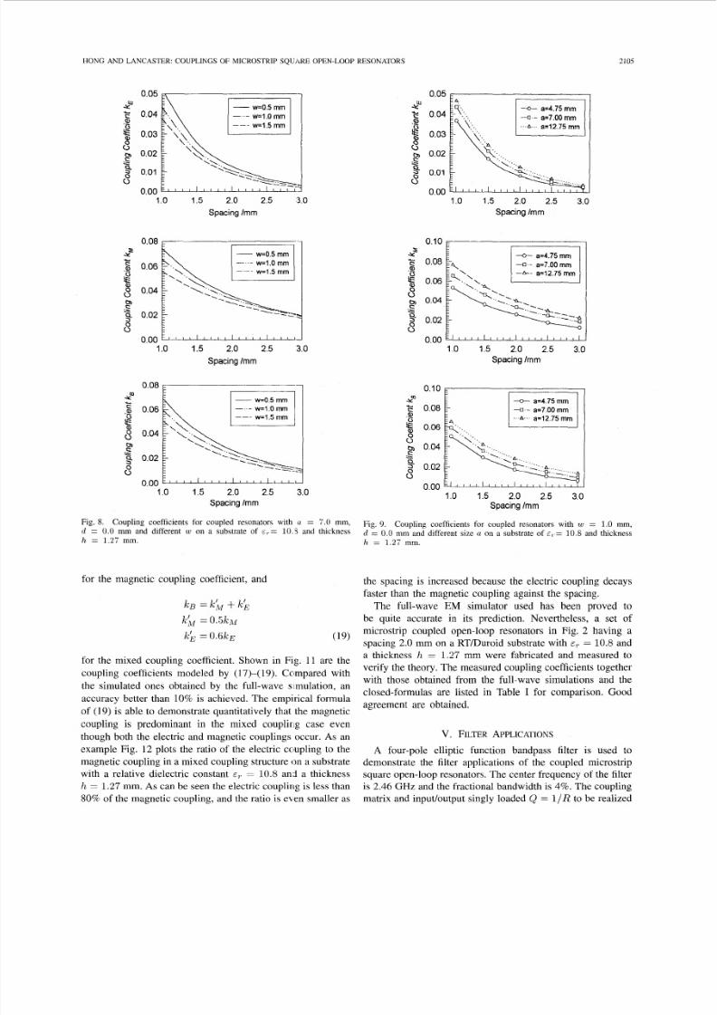
Fig. 8. Coupling coefficients for coupled resonators with (I = 7.0 m m,d = 0.0 mm and different w on a substrate of E ~ = 0.3 and thickness
h = 1.27 mm.
for the magnetic coupling coefficient, and
for the mixed coupling coefficient. Shown in Fig. 11 are the
coupling coefficients modeled by (17)-(19). Compared with
the simulated ones obtained by the full-wave simulation, anaccuracy better than 10% is achieved. The empirical formula
of (19) is able to demonstrate quantitatively that the magnetic
coupling is predominant in the mixed couplirig case even
though both the electric and magnetic couplings occur. As an
examp le Fig. 1 2 plots the ratio of the electric coupling to the
magnetic coupling in a m ixed coupling structure on a substrate
with a relative dielectric constant E, = 10.8 and a thickness
h = 1.27 mm. As can be seen the electric coupling is less than
80% of the magnetic coupling, and the ratio is e\ en smaller as
0.05
0.04
0.03
0.02
0.01
0.00
4.-=7.00 mm- - - A - - -a-12.75 m m
1.0 1.5 2.0 2.5 3.0
Spacing Im m
0 10
- 0 0 8 -I a=7 00 mm-A-- a=12 75 mm
9
8- 00 2
80 00
1 0 1 5 2 0 2 5 3 0
Spacing Im m
4.-=7.00 mm.. A- a=12.75 m m
1.0 1.5 2.0 2.5 3.0
Spacing Imm
Fig. 9. Coupling coefficients for coupled resonators with w = 1. 0 mm,d = 0. 0 mm and different size a on a substrate of E,-= 10.8 and thickness
h = 1 . 2 7 mm .
the spacing is increased because the electric coupling decays
faster than the magnetic coupling against the spacing.
The full-wave EM simulator used has been proved to
be quite accurate in its prediction. Nevertheless, a set of
microstrip coupled open-loop resonators in Fig. 2 having a
spacing 2.0 mm on a RTDu roid substrate with E, = 10.8 an d
a thickness h = 1.27 mm were fabricated and measured to
verify the theory. The measured cou pling coefficients together
with those obtained from the full-wave simulations and theclosed-formulas are listed in Table I for comparison. Good
agreement are obtained.
V. FILTER PPLICATIONS
A four-pole elliptic function bandpass filter is used to
demonstrate the filter applications of the coupled microstrip
square open-loop resonators. The center frequency of the filter
is 2.46 G H z and the fractional bandwidth is 4%. The coupling
matrix and input/output singly loaded Q = I /R to be realized

8/3/2019 Couplings of Micro Strip Square Open-loop Resonators for Cross-coupled Planar Microwave Filters
http://slidepdf.com/reader/full/couplings-of-micro-strip-square-open-loop-resonators-for-cross-coupled-planar 8/11
2106 IEEE TRANSACTIONS ON MICROWAVE THEORY AN D TECHNIQUES, VOL. 44, NO. 12, DECEMBER 1996
1 0 1 5 2 0 2 5 3 0
Spacing mm
- d = l Om m
1 0 1 5 2 0 2 5 3 0
Spacing l m m
- d = l O m m
1 0 1 5 2 0 2 5 3 0
Spacing mmFig. 10. Coupling coefficients of the three types of coupled microstrip square
open- loop resonators with a = 7.0 mm , w = 1.0 mm and different offset d
on a substrate of E ? = 10.8 and thickness h = 1 . 2 i m m.
ar e
0 0.0261 0 -0.0029
0
(20)
0.0261 0 0.022
-0.0029 0 0.026 1
0 0.022 0 0.0261= [
R = 0.035 01.
The positive couplings = = = an d
M23 = M32 are realized by the mixed and magn etic couplings,respectively, while the negative coupling A414 = ar erealized by the electric coupling. The inputloutput loads are
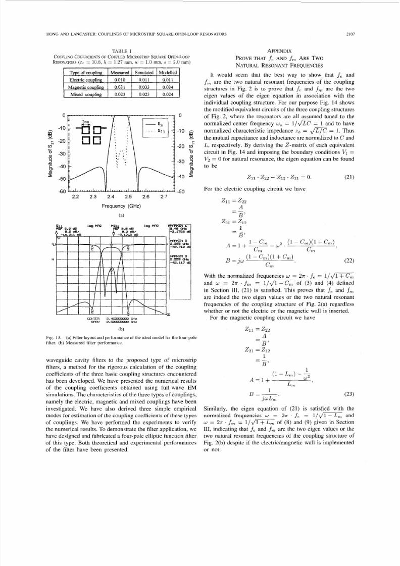
achieved via tapped feed lines [20]. Fig. 13(a) shows the
layout of the filter and the frequency responses com puted by an
ideal circuit model. The filter was fabricated on a RTDuroid
substrate with a relative dielectric constant of 10.8 and a
thickness of 1.27 mm. The measured filter performance is
given in Fig. 13(b). The passband insertion loss is about 2.2
dB. This is mainly due to the conductor loss for a measured
resonator &If 200.
- - modelled (&,=IO 8)
-- modelled ( ~ , =25 )
0 full-wave
o full-waveA full-wave
0 06
?? 00 5
8 004
8 003
C
0,
3 00 2
800 1
0 000 75 1 00 12 5 150 1 75 2 00 2 25 2 50
Normalized spacing s lh
075 100 125 150 175 200 225 250
Normalized spacingslh
0 08
s006
g2 00 4
0,
s3 00 2
s
modelled
modelled
modelled
full-wavefull-wave
full-wave
(a/h=3.7402)
(a/h=5.5118)
(a/h=l0.0394)
- odelled (w/h=0.3937)- - modelled (w/h=0.7874)
modelled (w/h=1.1811)
0 full-wave
full-waveA full-wave
0.00-.7 5 1.00 1.25 1.50 1.75 2.00 2.25 2.50
Normalized spacing sl h
Fig. 11 .formulas to those simulated uying the full-wave EM simulator.
Comparison of the coupling coefficients modeled using the closed
1.0 L
w/h=0.7874a/h-5.5118e,=10.8
0.0
0.75 1.00 1.25 1.50 1.75 2.00 2.25 2.50
Normalized spacing sl h
Fig. 12.coupling structure, showing the magnetic coupling is predominant.
Ratio of the electric coupling to the magnetic coupling in the mixed
VI . CONCLUSION
We have proposed a new type of planar c ross-coupled filters
using coupled microstrip square open-loop resonators. In order
to apply the design technique which is widely used for the
8/3/2019 Couplings of Micro Strip Square Open-loop Resonators for Cross-coupled Planar Microwave Filters
http://slidepdf.com/reader/full/couplings-of-micro-strip-square-open-loop-resonators-for-cross-coupled-planar 9/11
HONG AND LANCASTER: COUPLINGS OF MICROSTRIP SQUARE OPEN-LOOP RESONATORS
TABLE I
COUPLINGOEFFICIENTSF COUPLED ICROSTRIPQUA RE PEN-LOOP
RESONATORSE ~ 10.8, h = 1 .2 7 m m, w = 1.0 mm, 5 = 2. 0 mm )
ielled
011
034
--
0
-10
- -20
-30
‘e -40
-50
-60
hsmm*-
733
0,
I
3
2.2 2.3 2.4 2.5 2.6 2.7
Frequency (GHz)
(a )
0
-10 gs
-20 m-
-30 2
...Y-O
a,J
Cln
-40
-50
cain33 2.-c*b
9D(w 0.-m
(b)
Fig. 13.filter. (b) Measured filter performance.
(a) Filter layout and performance of the ideal model for the four-pole
waveguide cavity filters to the proposed type of microstrip
filters, a method for the rigorous calculation of the coupling
coefficients of the three basic coupling structures encountered
has been developed. We have presented the numerical resultsof the coupling coefficients obtained using fiill-wave EM
simulations. The characteristics of the three types of couplings,
namely the electric, magnetic and mixed couplirlgs have been
investigated. We have also derived three simple empirical
modes for estimation of the coupling coefficients of these types
of couplings. We have performed the experiments to verify
the nu merical results. To demon strate the filter application, we
have designed and fabricated a four-pole elliptic function filter
of this type. Both theoretical and experimental performances
of the filter have been presented.
~
2107
APPENDIX
NATURAL ESONAN T REQUENCIES
It would seem that the best way to show that fe an d
f,. are the two natural resonant frequencies of the coupling
structures in Fig. 2 is to prove that f e an d fm are the two
eigen values of the eigen equation in association with theindividual coupling structure. For our purpose Fig. 14 shows
the modified equivalent circuits of the three co upling structures
of Fig. 2, where the resonators are all assumed tuned to the
normalized center frequency w, = l/m 1 and to have
normalized characteristic impedance z , = = 1. Thus
the mutual cap acitance and inductance are normalized to C an d
L, respectively. By deriving the 2-matrix of each equivalent
circuit in Fig. 14 and imposing the boundary conditions VI =
Vz = 0 for natural resonance, the eigen equation can b e found
to be
PROVE THAT f e AN D f m ARE TW O
For the electric coupling circuit we have
With the normalized frequencies w = 2n . e = 1 / J m
an d w = 2n . fm = l/J= of (3) an d (4) defined
in Section 111, (21) is satisfied. This proves that fe an d fm
are indeed the two eigen values or the two natural resonant
frequencies of the coupling structure of Fig. 2(a) regardless
whether or not the electric or the magnetic wall is inserted.
For the magnetic coupling circuit we have
211 = z 2 2
A
B’
2 2 1 = 2 1 2
-1
B’- -
1(1- L,) --
= l + W 2
L ,
(23)
Similarly, the eigen equation of (21) is satisfied with the
normalized frequencies w = 271. . f C = 1/Jmnd
w = 2n . f m = l / d m f (8) an d (9) given in Section
111, indicating that f e an d fm are the two eigen values or the
two natural resonant frequencies of the coupling structure of
Fig. 2(b) despite if the electric/magnetic wall is implemented
or not.
1B=-.
j W L ,

8/3/2019 Couplings of Micro Strip Square Open-loop Resonators for Cross-coupled Planar Microwave Filters
http://slidepdf.com/reader/full/couplings-of-micro-strip-square-open-loop-resonators-for-cross-coupled-planar 10/11
2 I08 IEEE TRANSACTIONS ON MICROWAVE THEORY AND TECHNIQUES, VOL. 44, NO. 12, DECEMBER 1996
Electric Coupling
--I --fv -to
v,=o v,=o
~ I F IF Ii0 0
Magnetic Coupling
1,=o
Mixed Coupling
Fig. 14. Normalizcd equivalent circuits of the electric, the magnetic, andthe mixed coupling structures for deriving the eigen equation of the coupled
resonator circuit.
For the mixed coupling circuit we have
A s can be seen Zl10 = 0 for the normalized frequency
w = 27r . ,fin = l/d(lL L ) ( l - ChL)of (13) an d
Zl le = 0 for the normalized frequency w = 2;r . f e =
1/d(1 LirL)( l C;n) f (14) so that, again, (21) is satisfied,
which give a proof that f c an d fm defined by (13) an d (14) ar e
the two eigen values or the two natural resonant frequencies
of the coupling structure of Fig. 2(c) without inserting the
electric wall or the magnetic wall.
REFERENCES
S. Darlington, “Synthesis of reactance four poles which produce pre-
scribed insertion loss characteristics,” J . Math. Phys. , vol. 18, pp .
257-353, Sept. 1939.R. Levy and S. B. Cohn, “A history of microwave filter research, design,
and development,” IEEE Trans. Microwave T heoty Tech. , vol. MTT-32,
pp. 1055-1067, Sept. 1984.
J. A. Curits and S. J. Fiedziuszko, “Miniature dual mode microstripfilters,” in IEEE MTT-S, Dig . , 1991 , pp . 4434 46 .-, “Multi-layered planar filters based on aperture coupled dual
mode microstrip or stripline resonators,” in IEEE MTT-S Dig. , 1992,pp. 1203-1206.G. L. M atthaei and G. L. Hey-Shipton, “Nove l staggered resonator arraysuperconducting 2.3 GHr bandpass filter,” in IEEE M T T - S Dig.,un e1993, pp. 1269-1272.S. J. Hedges and R. G . Humphreys, “An extracted pole microstrip elliptic
function filter using high temperature superconductors,” in Proc. Eur.
Microwave C o n f , 1994, pp. 517-521.M. Sagawa, K. Takahashi, and M. Makimoto, “Miniaturized hairpin
resonator filters and their application to receiver front-end M IC’s,” IE E E
Trans. Microwave Th eory Tech. , vol. 37, pp. 1991-1997, Dec . 1989.M. Makimo to, “Microstripline split-ring resonators and their application
to bandpass filters,” Electronics and Communication in Japan. Ne wYork: Wiley, 1989, vol. 12, no. 5, pt. 2, pp. 104-112.J. S. Hong and M. J. Lancaster, “Realization of quasielliptic function
filter using dual-mode microstrip square loop resonators,” Elec. Lett.,vol. 31, pp. 2085-2086, 1995.S. J. Yao, R. R. Bonetti, and A. E. Williams, “Generalized dual-plane
multicoupled line filters,” IEEE Trans. Microwave Theory Tech. , vol .
41 , pp. 2182-2189, Dec. 1993.R. R. Bonetti and A. E. Williams, “New design techniques for coupled
line filters with transmission zeros,” in Proc. Eur. Microwave Con5,1993, pp. 240-243.J. S. Hong and M. J . Lancaster, “Microstrip bandpass filter using
degenerate modes of a novel meander loop resonator,” IEEE Microwave
Guided Wave L e x , vol. 5 , pp. 371-372, 1995.- “Canonical microstrip filter using square open-loop resonators,”
Elec. Lett., vol. 31 , pp. 2020-2022, 1995.C. Rauscher, “Microwave channelized active filters-A new modular
approach to achieving compactness and high selectivity,” IEEE Trans.
Microwave Theory Tech., vol. 44, pp. 122-132, Jan. 1996.A. E. Atia and A. E. Williams, “Narrow-bandpass waveguide filters,”
IEEE Tranr. Microwave Theory Tech. , vol. MT T-20, pp. 258-265, Apr.1972.
A. E. Atia, A. E. Williams, and R . W. Newcomb, “Narrow-bandmultiple-coupled cavity synthesis,” IEEE Trans. Circ. Syr., vol. CAS-21,
pp. 649-655, Sept. 1974.B. I. Bleaney and B. Bleaney, Electriciw and Magnetism, 3rd ed.
Oxford: Oxford Univ. Press, 1976, vol. 1 , ch. 7.C. G. Montgomery. R. H. Dicke, and E . M. Purcell, Principles of
Microwave Circuit.y.EM User’s Manual. Sonnet Software, Inc., Version 2.4, 1993.J. S. Wong, “Microstrip tapped-line filter design,” IEEE Trans . Mi-
crowave Theorj Tech. , vol. MTT-27, pp. 44-50, Jan. 1979.
New York: McGraw-Hill, 1948, ch. 4.
Jia-Sheng Hong (M’94) received the D.Phi1. de-
gree in engineering science from Oxford University,U.K. , in 1994. In 1983, he was awarded a Friedrich
Ebert Scholarship.From 1979 to 1983, he worked at Fuzhou Uni-
versity, China, as a Teachingmesearch Assistant inradio engineering. He visited Karlsruhe University,
Germany, where he worked on microwave andmillimeter-wave techniques from 1984 to 1985. In1986, he returned to Fuzhou University as a Lecturer
in microwave communications. In 1990. he wasawarded a K . C. Wong Scholarship by Oxford University and became a
graduate member of St. Peter’s College at Oxford University, where heconducted research in electromagnetic theory and applications. Since 1994,
he has been a Research Fellow at Birmingham University, U.K. His current
interests include RF and microwave devices for communications, antennas,
microwave applications of high temperature superconductors, electromagneticmodeling, and the genetic approach for signal processing and optimization.

8/3/2019 Couplings of Micro Strip Square Open-loop Resonators for Cross-coupled Planar Microwave Filters
http://slidepdf.com/reader/full/couplings-of-micro-strip-square-open-loop-resonators-for-cross-coupled-planar 11/11
HONG AND LANCASTER: COUPLINGS OF MICROSTRIP SQUARE OPEN-LOOP RESONATORS
Michael J. Lancaster (M’94) received the degreein physics from Bath University, U K. , in 1980. He
received the Ph.I>. degree in 1984 for research intononlinear underwater acoustics.
He joined the surface acoustic wave (SAW) groupat the Department of Engineering Science at Oxford
University as a Research Fellow. The research wasin the design of new, novel SAW devices, including
filters and filter banks. These de\,ices worked inthe frequency range 10 MHz-1 G-Iz. In 1987, hebecame a Lecturer at The University of Birming-
ham in the School of Electronic and Electrical Engineering, lecturing inelectromagnetic theory and m icrowave engineering. Shortly alter he joined the
school, he began the study of the science and applications of high temperature
superconductors, working mainly at microwave frequencie i. Currently, he
heads the Electronic and Materials Devices group as a Reader. His presentpersonal research interests include microwave filters and antennas, as well
as the high frequency properties and applications of a number of novel anddiverse materials.
2109