— CONTROL SEC TION 5
IEC manual motor starters

5-2 IEC MANUAL MOTOR STARTERS, CONTROL SECTION 5

5-3IEC MANUAL MOTOR STARTERS, CONTROL SECTION 5
— Table of contents
Manual motor starters5-4 Overview5-6 MS116 manual motor starters5-7 MS132 manual motor starters5-8 MS132-K manual motor starters with push-in spring
terminals5-9 MS165 manual motor starters5-10 MO132 manual motor starters magnetic only5-11 MO165 manual motor starters magnetic only
Circuit breakers for transformer protection5-12 MS132-T circuit breakers for transformer protection5-13 MS132-KT circuit breakers for transformer protection
with push-in spring terminals
5-14 Accessories
DRAS09 … DRAS16 enclosed direct-on-line starters5-22 4 to 7.5 kW, protected by thermal overload relays, AC or
DC operated5-24 Up to 7.5 kW and 10 hp, protected by thermal overload
relays, AC operated HF0.6, HF2.4, HF9 electronic compact starters5-26 Direct-on-line starter5-27 Reversing starter

5-4 IEC MANUAL MOTOR STARTERS, CONTROL SECTION 5
—Manual motor startersOverview
Table for short-circuit ratings for 400/415 V ACStandard range Performance rangeMS116 MS132, MS165
Selection parameters
Rated operational power
Setting range for thermal release
TypeShort-circuit breaking capacity Type
Short-circuit breaking capacity
Icu Ics Icu Ics0.03 kW² 0.1 … 0.16 A MS116-0.16 100 kA 50 kA MS132-0.16³ 100 kA 100 kA0.06 kW 0.16 … 0.25 A MS116-0.25 100 kA 50 kA MS132-0.25³ 100 kA 100 kA0.09 kW 0.25 … 0.4 A MS116-0.4 100 kA 50 kA MS132-0.4³ 100 kA 100 kA0.18 kW 0.4 … 0.63 A MS116-0.63 100 kA 50 kA MS132-0.63³ 100 kA 100 kA0.25 kW 0.63 … 1.0 A MS116-1.0 100 kA 50 kA MS132-1.0³ 100 kA 100 kA0.55 kW 1.0…1.6 A MS116-1.6 100 kA 50 kA MS132-1.6³ 100 kA 100 kA0.75 kW 1.6…2.5 A MS116-2.5 75 kA 50 kA MS132-2.5³ 100 kA 100 kA1.5 kW 2.5…4.0 A MS116-4.0 75 kA 50 kA MS132-4.0³ 100 kA 100 kA2.2 kW 4.0…6.3 A MS116-6.3 50 kA 50 kA MS132-6.3³ 100 kA 100 kA4.0 kW 6.3…10 A MS116-10 50 kA 50 kA MS132-10³ 100 kA 100 kA5.5 kW 8…12 A MS116-12 50 kA 25 kA MS132-12 100 kA 100 kA7.5 kW 10…16 A MS116-16 16 kA 16 kA MS132-16³ / MS165-16 100 kA 100 kA7.5 kW 14 ... 20 A – – – MS165-20 100 kA 100 kA7.5 kW 16…20 A MS116-20 16 kA 10 kA MS132-20³ 100 kA 100 kA11 kW 18 … 25 A – – – MS165-25 100 kA 100 kA11 kW 20…25 A MS116-25 16 kA 10 kA MS132-25³ 50 kA 50 kA15 kW 25…32 A MS116-32 16 kA 10 kA MS132-32³ 50 kA 25 kA15 kW 23 ... 32 A – – – MS165-32 100 kA 100 kA22 kW 30 ... 42 A – – – MS165-42 50 kA 50 kA22 kW 40 ... 54 A – – – MS165-54 50 kA 30 kA25 kW – – – – – – –30 kW 52 ... 65 A – – – MS165-65 50 kA 30 kA37 kW 62 ... 73 A – – – MS165-73 30 kA 30 kA45 kW 70 ... 80 A – – – MS165-80 30 kA 30 kA² 690 V AC³ Available with push-in spring terminals.
Type MS116 MS132 MS165Thermal and electromagnetic protection Yes Yes YesElectromagnetic protection – – –Phase loss sensitivity Yes Yes YesSwitch position ON/OFF ON/OFF/TRIP ON/OFF/TRIPMagnetic trip indication – Yes YesLockable handle without accessories – Yes YesDisconnecting feature Yes Yes YesWidth 45 mm 45 mm 55 mmRated operational current Ie 0.10 ... 32 A 0.10 ... 32 A 10 ... 80 ASetting range 0.10 ... 32 A 0.10 ... 32 A 10 ... 80 AAmbient air temperature -25 ... +55°C¹ -25 ... +60°C¹ -25 ... +60°C¹¹ Compensated
AccessoriesAuxiliary contact HKF1, HK1Signaling contact
for tripped alarm SK1for short-circuit alarm – CK1
Shunt trip AA1Undervoltage release UA1

5-5IEC MANUAL MOTOR STARTERS, CONTROL SECTION 5
—Manual motor startersOverview
Table for short-circuit ratings for 400/415 V ACPerformance range Transformer protectionMO132, MO165 MS132-T
Selection parameters
Rated operational power
Setting range for thermal release
TypeShort-circuit breaking capacity Type
Short-circuit breaking capacity
Icu Ics Icu / Ics
0.03 kW² 0.1 … 0.16 A MO132-0.16 100 kA 100 kA MS132-0.16T³ 100 kA0.06 kW 0.16 … 0.25 A MO132-0.25 100 kA 100 kA MS132-0.25T³ 100 kA0.09 kW 0.25 … 0.4 A MO132-0.4 100 kA 100 kA MS132-0.4T³ 100 kA0.18 kW 0.4 … 0.63 A MO132-0.63 100 kA 100 kA MS132-0.63T³ 100 kA0.25 kW 0.63 … 1.0 A MO132-1.0 100 kA 100 kA MS132-1.0T³ 100 kA0.55 kW 1.0…1.6 A MO132-1.6 100 kA 100 kA MS132-1.6T³ 100 kA0.75 kW 1.6…2.5 A MO132-2.5 100 kA 100 kA MS132-2.5T³ 100 kA1.5 kW 2.5…4.0 A MO132-4.0 100 kA 100 kA MS132-4.0T³ 100 kA2.2 kW 4.0…6.3 A MO132-6.3 100 kA 100 kA MS132-6.3T³ 100 kA4.0 kW 6.3…10 A MO132-10 100 kA 100 kA MS132-10T³ 100 kA5.5 kW 8…12 A MO132-12 100 kA 100 kA MS132-12T 100 kA7.5 kW 10…16 A MO132-16 / MO165-16 100 kA 100 kA MS132-16T³ 100 kA7.5 kW 14 ... 20 A MO165-20 100 kA 100 kA – –7.5 kW 16…20 A MO132-20 100 kA 100 kA MS132-20T³ 100 kA11 kW 18 … 25 A – – – – –11 kW 20…25 A MO132-25 / MO165-25 50 kA / 100 kA 50 kA / 100 kA MS132-25T³ 50 kA15 kW 25…32 A MO132-32 50 kA 25 kA Transformer protection:
The instantaneous short-circuit current setting is 20 times the rated operational current.
15 kW 23 ... 32 A MO165-32 100 kA 100 kA
22 kW 30 ... 42 A MO165-42 50 kA 50 kA
22 kW 40 ... 54 A MO165-54 50 kA 30 kA25 kW – – – –30 kW 52 ... 65 A MO165-65 50 kA 30 kA37 kW 62 ... 73 A MO165-73 30 kA 30 kA45 kW 70 ... 80 A MO165-80 30 kA 30 kA² 690 V AC³ Available with push-in spring terminals.
Type MO132 MO165 MS132-TThermal and electromagnetic protection – – YesElectromagnetic protection Yes Yes –Phase loss sensitivity – – YesSwitch position ON/OFF/TRIP ON/OFF/TRIP ON/OFF/TRIPMagnetic trip indication – – YesLockable handle without accessories Yes Yes YesDisconnecting feature Yes Yes YesWidth 45 mm 55 mm 45 mmRated operational current Ie 0.16 ... 32 A 16 ... 80 A 0.16 ... 25 ASetting range – – 0.10 ... 25 AAmbient air temperature -25 ... +60°C -25 ... +60°C -25 ... +60°C¹¹ Compensated
AccessoriesAuxiliary contact HKF1, HK1 HKF1, HK1Signaling contact
for tripped alarm SK1 SK1for short-circuit alarm – CK1
Shunt trip AA1 AA1Undervoltage release UA1 UA1

5-6 IEC MANUAL MOTOR STARTERS, CONTROL SECTION 5
—Manual motor startersMS116
0.10 to 32 A – with thermal and electromagnetic protection
Rated operational power400 V AC-3, AC-3e
Setting range
Short-circuit breakingcapacity Ics at 400 V AC
Rated instantaneous short-circuit current setting li
Type Order codeWeight(1 pce)
kW A kA A kg0.03¹ 0.10 ... 0.16 50 2.00 MS116-0.16 1SAM250000R1001 0.2250.06 0.16 ... 0.25 50 3.10 MS116-0.25 1SAM250000R1002 0.2250.09 0.25 ... 0.40 50 5.00 MS116-0.4 1SAM250000R1003 0.2250.18 0.40 ... 0.63 50 7.90 MS116-0.63 1SAM250000R1004 0.2250.25 0.63 ... 1.00 50 12.5 MS116-1.0 1SAM250000R1005 0.2250.55 1.00 ... 1.60 50 20.0 MS116-1.6 1SAM250000R1006 0.2650.75 1.60 ... 2.50 50 31.3 MS116-2.5 1SAM250000R1007 0.2651.50 2.50 ... 4.00 50 50.0 MS116-4.0 1SAM250000R1008 0.2652.20 4.00 ... 6.30 50 78.8 MS116-6.3 1SAM250000R1009 0.2654.00 6.30 ... 10.0 50 150 MS116-10 1SAM250000R1010 0.2655.50 8.00 ... 12.0 25 180 MS116-12 1SAM250000R1012 0.2657.50 10.0 ... 16.0 16 240 MS116-16 1SAM250000R1011 0.2657.50 16.0 ... 20.0 10 300 MS116-20 1SAM250000R1013 0.31011.0 20.0 ... 25.0 10 375 MS116-25 1SAM250000R1014 0.31015.0 25.0 ... 32.0 10 480 MS116-32 1SAM250000R1015 0.310
Mounted auxiliary contacts 1 N.O. + 1 N.C.0.03¹ 0.10 ... 0.16 50 2.00 MS116-0.16-HKF1-11 1SAM250005R1001 0.2400.06 0.16 ... 0.25 50 3.10 MS116-0.25-HKF1-11 1SAM250005R1002 0.2400.09 0.25 ... 0.40 50 5.00 MS116-0.4-HKF1-11 1SAM250005R1003 0.2400.18 0.40 ... 0.63 50 7.90 MS116-0.63-HKF1-11 1SAM250005R1004 0.2400.25 0.63 ... 1.00 50 12.5 MS116-1.0-HKF1-11 1SAM250005R1005 0.2400.55 1.00 ... 1.60 50 20.0 MS116-1.6-HKF1-11 1SAM250005R1006 0.2800.75 1.60 ... 2.50 50 31.3 MS116-2.5-HKF1-11 1SAM250005R1007 0.2801.50 2.50 ... 4.00 50 50.0 MS116-4.0-HKF1-11 1SAM250005R1008 0.2802.20 4.00 ... 6.30 50 78.8 MS116-6.3-HKF1-11 1SAM250005R1009 0.2804.00 6.30 ... 10.0 50 150 MS116-10.0-HKF1-11 1SAM250005R1010 0.2805.50 8.00 ... 12.0 25 180 MS116-12.0-HKF1-11 1SAM250005R1012 0.2807.50 10.0 ... 16.0 16 240 MS116-16.0-HKF1-11 1SAM250005R1011 0.2807.50 16.0 ... 20.0 10 300 MS116-20-HKF1-11 1SAM250005R1013 0.32611.0 20.0 ... 25.0 10 375 MS116-25-HKF1-11 1SAM250005R1014 0.32615.0 25.0 ... 32.0 10 480 MS116-32-HKF1-11 1SAM250005R1015 0.326
Note: Manual motor starters should always be selected so that the actual motor current is within the setting range.¹ 690 V
2CD
C24
100
4V0
017
MS116-16
MS116-25
2CD
C24
1019
V0
017
MS116-0.16-HKF1-11
2CD
C24
1020
V0
017
MS116-32-HKF1-11
2CD
C24
1017
V0
017
5-7IEC MANUAL MOTOR STARTERS, CONTROL SECTION 5
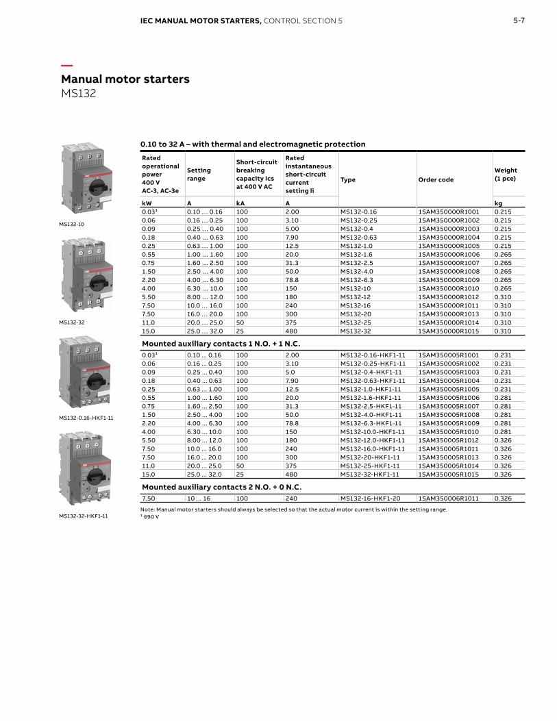
—Manual motor startersMS132
0.10 to 32 A – with thermal and electromagnetic protection
Rated operational power400 V AC-3, AC-3e
Setting range
Short-circuit breaking capacity Ics at 400 V AC
Rated instantaneous short-circuit current setting li
Type Order codeWeight(1 pce)
kW A kA A kg0.03¹ 0.10 … 0.16 100 2.00 MS132-0.16 1SAM350000R1001 0.2150.06 0.16 … 0.25 100 3.10 MS132-0.25 1SAM350000R1002 0.2150.09 0.25 … 0.40 100 5.00 MS132-0.4 1SAM350000R1003 0.2150.18 0.40 … 0.63 100 7.90 MS132-0.63 1SAM350000R1004 0.2150.25 0.63 … 1.00 100 12.5 MS132-1.0 1SAM350000R1005 0.2150.55 1.00 … 1.60 100 20.0 MS132-1.6 1SAM350000R1006 0.2650.75 1.60 … 2.50 100 31.3 MS132-2.5 1SAM350000R1007 0.2651.50 2.50 … 4.00 100 50.0 MS132-4.0 1SAM350000R1008 0.2652.20 4.00 … 6.30 100 78.8 MS132-6.3 1SAM350000R1009 0.2654.00 6.30 … 10.0 100 150 MS132-10 1SAM350000R1010 0.2655.50 8.00 … 12.0 100 180 MS132-12 1SAM350000R1012 0.3107.50 10.0 … 16.0 100 240 MS132-16 1SAM350000R1011 0.3107.50 16.0 … 20.0 100 300 MS132-20 1SAM350000R1013 0.31011.0 20.0 … 25.0 50 375 MS132-25 1SAM350000R1014 0.31015.0 25.0 … 32.0 25 480 MS132-32 1SAM350000R1015 0.310
Mounted auxiliary contacts 1 N.O. + 1 N.C.0.03¹ 0.10 ... 0.16 100 2.00 MS132-0.16-HKF1-11 1SAM350005R1001 0.2310.06 0.16 ... 0.25 100 3.10 MS132-0.25-HKF1-11 1SAM350005R1002 0.2310.09 0.25 ... 0.40 100 5.0 MS132-0.4-HKF1-11 1SAM350005R1003 0.2310.18 0.40 ... 0.63 100 7.90 MS132-0.63-HKF1-11 1SAM350005R1004 0.2310.25 0.63 ... 1.00 100 12.5 MS132-1.0-HKF1-11 1SAM350005R1005 0.2310.55 1.00 ... 1.60 100 20.0 MS132-1.6-HKF1-11 1SAM350005R1006 0.2810.75 1.60 ... 2.50 100 31.3 MS132-2.5-HKF1-11 1SAM350005R1007 0.2811.50 2.50 ... 4.00 100 50.0 MS132-4.0-HKF1-11 1SAM350005R1008 0.2812.20 4.00 ... 6.30 100 78.8 MS132-6.3-HKF1-11 1SAM350005R1009 0.2814.00 6.30 ... 10.0 100 150 MS132-10.0-HKF1-11 1SAM350005R1010 0.2815.50 8.00 ... 12.0 100 180 MS132-12.0-HKF1-11 1SAM350005R1012 0.3267.50 10.0 ... 16.0 100 240 MS132-16.0-HKF1-11 1SAM350005R1011 0.3267.50 16.0 ... 20.0 100 300 MS132-20-HKF1-11 1SAM350005R1013 0.32611.0 20.0 ... 25.0 50 375 MS132-25-HKF1-11 1SAM350005R1014 0.32615.0 25.0 ... 32.0 25 480 MS132-32-HKF1-11 1SAM350005R1015 0.326
Mounted auxiliary contacts 2 N.O. + 0 N.C.7.50 10 ... 16 100 240 MS132-16-HKF1-20 1SAM350006R1011 0.326
Note: Manual motor starters should always be selected so that the actual motor current is within the setting range.¹ 690 V
2CD
C24
100
2V0
013
MS132-10
2CD
C24
100
6V
00
17
MS132-32
MS132-0.16-HKF1-11
MS132-32-HKF1-11
2CD
C24
1021
V0
017
2CD
C24
1022
V0
017

5-8 IEC MANUAL MOTOR STARTERS, CONTROL SECTION 5
—Manual motor startersMS132-K with push-in spring terminals
0.10 to 32 A – with thermal and electromagnetic protection
Rated operational power 400 V AC-3, AC-3e
Setting range
Short-circuit breaking capacity Ics at 400 V AC
Rated instantaneous short-circuit current setting li
Type Order codeWeight (1 pce)
kW A kA A kg0.03¹ 0.10 … 0.16 100 2.00 MS132-0.16K 1SAM350010R1001 0.2560.06 0.16 … 0.25 100 3.10 MS132-0.25K 1SAM350010R1002 0.2560.09 0.25 … 0.40 100 5.00 MS132-0.4K 1SAM350010R1003 0.2560.18 0.40 … 0.63 100 7.90 MS132-0.63K 1SAM350010R1004 0.2560.25 0.63 … 1.00 100 12.5 MS132-1.0K 1SAM350010R1005 0.2560.55 1.00 … 1.60 100 20.0 MS132-1.6K 1SAM350010R1006 0.2980.75 1.60 … 2.50 100 31.3 MS132-2.5K 1SAM350010R1007 0.2801.50 2.50 … 4.00 100 50.0 MS132-4.0K 1SAM350010R1008 0.2862.20 4.00 … 6.30 100 78.8 MS132-6.3K 1SAM350010R1009 0.2894.00 6.30 … 10.0 100 150 MS132-10K 1SAM350010R1010 0.2967.50 10.0 … 16.0 100 240 MS132-16K 1SAM350010R1011 0.3167.50 16.0 … 20.0 100 300 MS132-20K 1SAM350010R1013 0.31711.0 20.0 … 25.0 50 375 MS132-25K 1SAM350010R1014 0.31615.0 25.0 … 32.0 25 480 MS132-32K 1SAM350010R1015 0.316
Note: Manual motor starters should always be selected so that the actual motor current is within the setting range.¹ 690 V
2CD
C24
1025
V0
017
MS132-32K

5-9IEC MANUAL MOTOR STARTERS, CONTROL SECTION 5
—Manual motor startersMS165
10 to 80 A – with thermal and electromagnetic protection
Rated operational power400 V AC-3, AC-3e
Setting range
Short-circuit breakingcapacity Ics at 400 V AC
Rated instantaneous short-circuit current setting li
Type Order codeWeight(1 pce)
kW A kA A kg7.5 10 ... 16 100 240 MS165-16 1SAM451000R1011 0.9507.5 14 ... 20 100 300 MS165-20 1SAM451000R1012 0.95011 18 ... 25 100 375 MS165-25 1SAM451000R1013 0.96015 23 ... 32 100 480 MS165-32 1SAM451000R1014 0.97022 30 ... 42 50 630 MS165-42 1SAM451000R1015 0.97022 40 ... 54 30 810 MS165-54 1SAM451000R1016 0.97030 52 ... 65 30 975 MS165-65 1SAM451000R1017 0.98037 62 ... 73 30 1022 MS165-73 1SAM451000R1018 1.00045 70 ... 80 30 1120 MS165-80 1SAM451000R1019 1.000
Note: Manual motor starters should always be selected so that the actual motor current is within the setting range.
MS165-65
2CD
C24
100
7V0
017

5-10 IEC MANUAL MOTOR STARTERS, CONTROL SECTION 5
—Manual motor startersMO132 magnetic only
0.16 to 32 A – with electromagnetic protection
Rated operational power400 V AC-3, AC-3e
Rated operationalcurrent
Short-circuit breaking capacity Ics at 400 V AC
Rated instantaneous short-circuit current setting li
Type Order codeWeight(1 pce)
kW A kA A kg0.03¹ 0.16 100 2.00 MO132-0.16 1SAM360000R1001 0.2150.06 0.25 100 3.10 MO132-0.25 1SAM360000R1002 0.2150.09 0.40 100 5.00 MO132-0.4 1SAM360000R1003 0.2150.12 0.63 100 7.90 MO132-0.63 1SAM360000R1004 0.2150.25 1.0 100 12.5 MO132-1.0 1SAM360000R1005 0.2150.55 1.6 100 20.0 MO132-1.6 1SAM360000R1006 0.2650.75 2.5 100 31.3 MO132-2.5 1SAM360000R1007 0.2651.5 4.0 100 50.0 MO132-4.0 1SAM360000R1008 0.2652.2 6.3 100 78.8 MO132-6.3 1SAM360000R1009 0.2654.0 10 100 125 MO132-10 1SAM360000R1010 0.2655.5 12 100 150 MO132-12 1SAM360000R1012 0.3107.5 16 100 200 MO132-16 1SAM360000R1011 0.3107.5 20 100 250 MO132-20 1SAM360000R1013 0.31011 25 50 313 MO132-25 1SAM360000R1014 0.31015 32 25 400 MO132-32 1SAM360000R1015 0.310
Note: For overload protection of motors, an appropriate thermal or electronic overload relay must be used.¹ 690 V
2CD
C24
1018
V0
017
MO132-6.3
2CD
C24
1015
V0
017
MO132-32
Page 2-14

5-11IEC MANUAL MOTOR STARTERS, CONTROL SECTION 5
—Manual motor startersMO165 magnetic only
16 to 80 A – with electromagnetic protection
Rated operational power400 V AC-3, AC-3e
Rated operational current
Short-circuit breaking capacity Ics at 400 V AC
Rated instantaneous short-circuit current setting li
Type Order codeWeight(1 pce)
kW A kA A kg7.5 16 100 240 MO165-16 1SAM461000R1011 0.9507.5 20 100 300 MO165-20 1SAM461000R1012 0.95011 25 100 375 MO165-25 1SAM461000R1013 0.96015 32 100 480 MO165-32 1SAM461000R1014 0.97022 42 50 630 MO165-42 1SAM461000R1015 0.97022 54 30 810 MO165-54 1SAM461000R1016 0.97030 65 30 975 MO165-65 1SAM461000R1017 0.98037 73 30 1022 MO165-73 1SAM461000R1018 1.00045 80 30 1120 MO165-80 1SAM461000R1019 1.000
Note: For overload protection of motors, an appropriate thermal or electronic overload relay must be used.
MO165-65
2CD
C24
100
8V
00
17

5-12 IEC MANUAL MOTOR STARTERS, CONTROL SECTION 5
—Circuit breakers for transformer protectionMS132-T
0.10 to 25 A – with thermal and electromagnetic protection
Setting range
Short-circuit breaking capacity Icsat 400 V AC
Rated instantaneous short-circuit current setting li
Type Order codeWeight(1 pce)
A kA A kg0.10 … 0.16 100 3.2 MS132-0.16T 1SAM340000R1001 0.2150.16 … 0.25 100 5 MS132-0.25T 1SAM340000R1002 0.2150.25 … 0.40 100 8 MS132-0.4T 1SAM340000R1003 0.2150.40 … 0.63 100 12.6 MS132-0.63T 1SAM340000R1004 0.2150.63 … 1.00 100 20 MS132-1.0T 1SAM340000R1005 0.2151.00 … 1.60 100 32 MS132-1.6T 1SAM340000R1006 0.2651.60 … 2.50 100 50 MS132-2.5T 1SAM340000R1007 0.2652.50 … 4.00 100 80 MS132-4.0T 1SAM340000R1008 0.2654.00 … 6.30 100 126 MS132-6.3T 1SAM340000R1009 0.2656.30 … 10.0 100 200 MS132-10T 1SAM340000R1010 0.2658.00 … 12.0 100 240 MS132-12T 1SAM340000R1012 0.31010.0 … 16.0 100 320 MS132-16T 1SAM340000R1011 0.31016.0 … 20.0 100 400 MS132-20T 1SAM340000R1013 0.31020.0 … 25.0 50 500 MS132-25T 1SAM340000R1014 0.3102C
DC
2410
02F
00
142C
DC
2410
09V
00
17
Page 2-29
MS132-10T
MS132-25T

5-13IEC MANUAL MOTOR STARTERS, CONTROL SECTION 5
—Circuit breakers for transformer protection MS132-KT with push-in spring terminals
0.10 to 25 A – with thermal and electromagnetic protection
Setting range
Short-circuit breaking capacity Icsat 400 V AC
Rated instantaneous short-circuit current setting li
Type Order codeWeight(1 pce)
A kA A kg0.10 … 0.16 100 3.2 MS132-0.16KT 1SAM340010R1001 0.2560.16 … 0.25 100 5 MS132-0.25KT 1SAM340010R1002 0.2560.25 … 0.40 100 8 MS132-0.4KT 1SAM340010R1003 0.2560.40 … 0.63 100 12.6 MS132-0.63KT 1SAM340010R1004 0.2560.63 … 1.00 100 20 MS132-1.0KT 1SAM340010R1005 0.2561.00 … 1.60 100 32 MS132-1.6KT 1SAM340010R1006 0.2981.60 … 2.50 100 50 MS132-2.5KT 1SAM340010R1007 0.2802.50 … 4.00 100 80 MS132-4.0KT 1SAM340010R1008 0.2864.00 … 6.30 100 126 MS132-6.3KT 1SAM340010R1009 0.2896.30 … 10.0 100 200 MS132-10KT 1SAM340010R1010 0.29610.0 … 16.0 100 320 MS132-16KT 1SAM340010R1011 0.31616.0 … 20.0 100 400 MS132-20KT 1SAM340010R1013 0.31720.0 … 25.0 50 500 MS132-25KT 1SAM340010R1014 0.316
MS132-KT

5-14 IEC MANUAL MOTOR STARTERS, CONTROL SECTION 5
Suitable forAuxiliary contacts N.O.
Auxiliary contacts N.C.
Description Type Order codePkgqty
Weight (1 pce)
kg
Auxiliary contacts – mountable on the front
MS116, MS132, MS165, MO132, MO165, MS132-T,MS132-K, MS132-KT
1 1 – HKF1-11 1SAM201901R1001 10 0.015
1 0 – HKF1-10 1SAM201901R1003 10 0.013
0 1 – HKF1-01 1SAM201901R1004 10 0.013
2 0 – HKF1-20 1SAM201901R1002 10 0.015
Auxiliary contacts – mountable on the right
MS116, MS132, MS165, MO132, MO165, MS132-T, MS132-K, MS132-KT
1 1 max. 2 pieces HK1-11 1SAM201902R1001 2 0.035
2 0 max. 2 pieces HK1-20 1SAM201902R1002 2 0.035
0 2 max. 2 pieces HK1-02 1SAM201902R1003 2 0.035
MS116, MS132, MO132, MS132-T, MS132-K, MS132-KT
2 0max. 2 pieceswith leading contacts
HK1-20L 1SAM201902R1004 2 0.035
Signaling contacts – mountable on the right
MS116, MS132, MS165, MO132, MO165, MS132-T, MS132-K, MS132-KT
1 1 for tripped alarm SK1-11 1SAM201903R1001 2 0.035
2 0 for tripped alarm SK1-20 1SAM201903R1002 2 0.035
0 2 for tripped alarm SK1-02 1SAM201903R1003 2 0.035
MS132, MS165, MS132-T, MS132-K, MS132-KT
1 1for short-circuit alarm
CK1-11 1SAM301901R1001 2 0.035
2 0for short-circuit alarm
CK1-20 1SAM301901R1002 2 0.035
0 2for short-circuit alarm
CK1-02 1SAM301901R1003 2 0.035
Note : For BEA connecting links with AF, AS and B mini contactors please refer to Control Catalog Section 2.
HKF1-11
1S
BC
1012
09
F00
14
HK1-11
1S
BC
1012
10F0
014
SK1-11
1SB
C10
128
6F0
014
CK1-11
1SB
C10
120
8F0
014
Page 2-35 —AccessoriesMS116, MS132, MS165, MO132, MO165, MS132-T, MS132-K, MS132-KT

5-15IEC MANUAL MOTOR STARTERS, CONTROL SECTION 5
—AccessoriesMS116, MS132, MS165, MO132, MO165, MS132-T
Suitable forRated control supply voltage
Type Order codePkgqty
Weight (1 pce)
50 HzV AC
60 HzV AC
kg
Shunt trips – mountable on the left
MS116, MS132, MS165, MO132, MO165, MS132-T
20 ... 24 20 ... 24 AA1-24 1SAM201910R1001 1 0.100110 110 AA1-110 1SAM201910R1002 1 0.100200 ... 240 200 ... 240 AA1-230 1SAM201910R1003 1 0.100350 ... 415 350 ... 415 AA1-400 1SAM201910R1004 1 0.100
Undervoltage releases – mountable on the left
MS116, MS132, MS165, MO132, MO165, MS132-T
20 24 UA1-20 1SAM201904R1010 1 0.10024 – UA1-24 1SAM201904R1001 1 0.10048 – UA1-48 1SAM201904R1002 1 0.10060 – UA1-60 1SAM201904R1003 1 0.100110 120 UA1-110 1SAM201904R1004 1 0.100– 208 UA1-208 1SAM201904R1008 1 0.100230 240 UA1-230 1SAM201904R1005 1 0.100400 – UA1-400 1SAM201904R1006 1 0.100415 480 UA1-415 1SAM201904R1007 1 0.100– 575 UA1-575 1SAM201904R1009 1 0.100
Note : For BEA..-4K push-in spring connecting links with AF09..K ... AF38..K please refer to Control Catalog Section 2 - "Connection accessories for starting solutions with push-in spring terminals".
1S
BC
1012
11F0
014
AA1-24
1S
BC
1012
12F0
014
UA1-24

5-16 IEC MANUAL MOTOR STARTERS, CONTROL SECTION 5
—AccessoriesWith push-in spring terminals
Suitable forAuxiliary contacts N.O.
Auxiliary contactsN.C.
Description Type Order codePkg qty
Weight (1 pce)
kg
Auxiliary contacts - mountable on the frontMS116, MS132, MS165 MO132, MO165, MS132-T,MS132-K, MS132-KT
1 1 – HKF1-11K 1SAM201901R1201 10 0.016
2 0 – HKF1-20K 1SAM201901R1202 10 0.016
Auxiliary contacts - mountable on the right
MS116, MS132, MS165 MO132, MO165, MS132-T,MS132-K, MS132-KT
1 1 max. 2 pieces HK1-11K 1SAM201902R1201 2 0.035
2 0 max. 2 pieces HK1-20K 1SAM201902R1202 2 0.035
0 2 max. 2 pieces HK1-02K 1SAM201902R1203 2 0.035
2 0with leading contacts
HK1-20LK 1SAM201902R1204 2 0.035
Signaling contacts - mountable on the rightMS116, MS132, MS165 MO132, MO165, MS132-T,MS132-K, MS132-KT
1 1 for tripped alarm SK1-11K 1SAM201903R1201 2 0.035
2 0 for tripped alarm SK1-20K 1SAM201903R1202 2 0.035
0 2 for tripped alarm SK1-02K 1SAM201903R1203 2 0.035
Page 2-372C
DC
2410
28V
00
17
2CD
C24
1027
V0
017
2CD
C24
1029
V0
017
SK1-11K
HKF1-11K
HK1-11K

5-17IEC MANUAL MOTOR STARTERS, CONTROL SECTION 5
Suitable for
Rated operational current
Number of manual motor starters
Number of lateral auxiliary contacts
Type Order codePkgqty
Weight (1 pce)
A kg
Three-phase busbars
MS116, MS132, MO132
65 2 0 PS1-2-0-65 1SAM201906R1102 10 0.03465 3 0 PS1-3-0-65 1SAM201906R1103 10 0.05565 4 0 PS1-4-0-65 1SAM201906R1104 10 0.07765 5 0 PS1-5-0-65 1SAM201906R1105 10 0.09865 2 1 PS1-2-1-65 1SAM201906R1112 10 0.03665 3 1 PS1-3-1-65 1SAM201906R1113 10 0.06065 4 1 PS1-4-1-65 1SAM201906R1114 10 0.08765 5 1 PS1-5-1-65 1SAM201906R1115 10 0.10865 2 2 PS1-2-2-65 1SAM201906R1122 10 0.04065 3 2 PS1-3-2-65 1SAM201906R1123 10 0.06765 4 2 PS1-4-2-65 1SAM201906R1124 10 0.09565 5 2 PS1-5-2-65 1SAM201906R1125 10 0.122
MS116, MS132, MO132
100 3 0 PS1-3-0-100 1SAM201916R1103 10 0.084100 4 0 PS1-4-0-100 1SAM201916R1104 10 0.117100 5 0 PS1-5-0-100 1SAM201916R1105 10 0.154100 3 1 PS1-3-1-100 1SAM201916R1113 10 0.094100 4 1 PS1-4-1-100 1SAM201916R1114 10 0.134100 5 1 PS1-5-1-100 1SAM201916R1115 10 0.172100 3 2 PS1-3-2-100 1SAM201916R1123 10 0.105
Note: busbars are only suitable for screw versions
Suitable for
Rated operational current
Rated cross section
Mounting form
Type Order codePkgqty
Weight (1 pce)
A mm² kg
Three-phase feeder terminals
MS116, MS132, MO132
65 25 Flat S1-M1-25 1SAM201907R1101 10 0.03865 25 High S1-M2-25 1SAM201907R1102 10 0.051
65 25UL/CSA Type E/F and IEC
S1-M3-25 1SAM201907R1103 10 0.042
100 35UL/CSA Type E/F and IEC
S1-M3-35 1SAM201913R1103 10 0.060
PS1-2-0-65
PS1-3-1-100
S1-M3-35
S1-M2-25
—AccessoriesMS116, MS132, MO132, MS132-T
5-18 IEC MANUAL MOTOR STARTERS, CONTROL SECTION 5
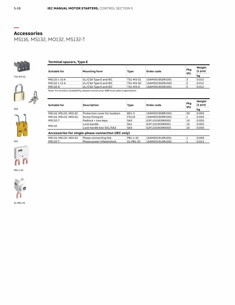
—AccessoriesMS116, MS132, MO132, MS132-T
Terminal spacers, Type E
Suitable for Mounting form Type Order codePkgqty
Weight (1 pce)
kgMS132 ≤ 10 A UL/CSA Type E and IEC TS1-M3-S1 1SAM301902R1001 2 0.012MS132 ≥ 12 A UL/CSA Type E and IEC TS1-M3-S2 1SAM301902R1002 2 0.012MS132-K UL/CSA Type E and IEC TS1-M3-K 1SAM301903R1001 2 0.012Note: For product availability, please consult your ABB local sales organization
Suitable for Description Type Order codePkgqty
Weight (1 pce)
kgMS116, MS132, MO132 Protection cover for busbars BS1-3 1SAM201908R1001 50 0.003MS116, MS132, MO132, MS132-T
Screw fixing kit FS116 1SAM201909R1001 1 0.020Padlock + two keys SA2 GJF1101903R0002 10 0.020
MS116Lock handle SA1 GJF1101903R0001 10 0.003Lock handle box SA1/SA2 SA3 GJF1101903R0003 10 0.050
Accessories for single-phase connection (IEC only)MS116, MS132, MO132, MS132-T
Phase connecting link PB1-1-32 1SAM201914R1001 1 0.009Phase power infeed block S1-PB1-25 1SAM201914R1002 1 0.013
TS1-M3-S1
SA2
SA1
PB1-1-32
S1-PB1-25

5-19IEC MANUAL MOTOR STARTERS, CONTROL SECTION 5
Three-phase busbars
Suitable for
Rated operational current
Number of manual motor starters
Number of lateral auxiliary contacts
Type Order codePkgqty
Weight (1 pce)
A kg
MS165, MO165
125 2 0 PS2-2-0-125 1SAM401920R1002 10 0.100125 3 0 PS2-3-0-125 1SAM401920R1003 10 0.162125 4 0 PS2-4-0-125 1SAM401920R1004 10 0.226125 2 2 PS2-2-2-125 1SAM401920R1022 10 0.117125 3 2 PS2-3-2-125 1SAM401920R1023 10 0.197125 4 2 PS2-4-2-125 1SAM401920R1024 10 0.277
Other busbar types on request.
Feeder block
Suitable for
Rated operational current
Rated cross section
Mounting form
Type Order codePkgqty
Weight (1 pce)
A mm² kg
MS165, MO165 125 50UL508A and IEC
S2-M3-50 1SAM401923R1003 1 0.172
Suitable for Description Type Order codePkgqty
Weight (1 pce)
kg
MS165, MO165Terminal shroud KA165 1SAM401922R1001 10 0.025Protection cover for busbars BS2-3 1SAM401921R1001 10 0.005Padlock + two keys SA2 GJF1101903R0002 10 0.020
PS2-2-0-125
PS2-3-0-125
S2-M3-50
KA165
BS2-3
SA2
—AccessoriesMS165, MO165

5-20 IEC MANUAL MOTOR STARTERS, CONTROL SECTION 5
Suitable for Description Color Type Order codePkgqty
Weight (1 pce)
kg
IP65 enclosures (NEMA Type 12)
MS116, MS132, MO132
Padlockable max. 3 padlocks with bail diameter 4 ... 6.5 mm
Yellow/red IB132-Y 1SAM201911R1011 1 0.370
Grey/black IB132-G 1SAM201911R1010 1 0.370
IP65 door mounting kits (NEMA Type 12)
MS116, MS132, MO132
Padlockable max. 3 padlocks with bail diameter 4 ... 6.5 mm
Yellow/red DMS132-Y 1SAM201912R1011 1 0.170
Grey/black DMS132-G 1SAM201912R1010 1 0.170
Indication I-O-T and ON-OFF-T.
IB132-Y
IB132-G
DMS132-Y
DMS132-G
—AccessoriesMS116, MS132, MO132

5-21IEC MANUAL MOTOR STARTERS, CONTROL SECTION 5
—AccessoriesMS116, MS132, MS165, MO132, MO165
Suitable for
DescriptionShaft length Color Type Order code
Pkgqty
Weight (1 pce)
mm pce kg
Shafts
MS116, MS132, MO132, MS165, MO165
For MSHD handles. Shaft diameter 6 mm. Shaft extension for door coupling driver.
85 – OXS6X85 1SCA101647R1001 1 0.020
105 – OXS6X105 1SCA108043R1001 1 0.020
130 – OXS6X130 1SCA101655R1001 1 0.030
180 – OXS6X180 1SCA101659R1001 1 0.040
IP64 handles (NEMA Type 1, 3R, 12)
MS116, MS132, MO132, MS165, MO165
Padlockable max. 3 padlocks with bail diameter 5 … 8 mm, door interlock in ON position defeatable, for use with 6 mm OXS6…types up to 180 mm or driver shafts MSOX.
– Black MSHD-LB¹ 1SAM201920R1001 1 0.065
– Yellow MSHD-LY¹ 1SAM201920R1002 1 0.065
– Black MSHD-LTB² 1SAM201920R1011 1 0.065
– Yellow MSHD-LTY² 1SAM201920R1012 1 0.065
Driver
MS116, MS132, MO132, MS165, MO165
Coupling driver for use with 6 mm OXS6… types up to 180 mm.
– – MSMN³ 1SAM101923R0002 1 0.002
– – MSMNO⁴ 1SAM101923R0012 1 0.002
Shaft alignment ring
MS116, MS132, MO132, MS165, MO165
The MSH-AR supports the long shafts for alignment to the handle inlet. It makes closing panel doors more easy. Use for OXS6X > 105 mm.
– – MSH-AR 1SAM201920R1000 1 0.010
Shaft supporter
MS116, MS132, MO132
With the MSAH it is possible to support the shaft in the extension of handle (MSHD). It is mandatory for the usage of shafts >130 mm.
– – MSAH1 1SAM201909R1021 1 0.035
¹ Indication I-O and ON-OFF (recommended for MS116)² Indication I-O and ON-OFF + Trip indication³ Coded - Positioning of ON indication dependent on mounting orientation of the MMS⁴ Uncoded - Positioning of ON indication independent of mounting orientation of the MMS.
MSHD-LB
MSHD-LY
MSMN
MSH-AR
MSAH1

5-22 IEC MANUAL MOTOR STARTERS, CONTROL SECTION 5
DRAS+ T16 to be ordered separately
—Enclosed direct-on-line startersDRAS09 … DRAS16
4 to 7.5 kW, protected by thermal overload relays, AC or DC operatedIEC - AC-3
Rated control circuit voltageUcOther control voltages see AS voltage code table
Control supply wiring
Type Order code
WeightPkg(1 pce)
Rated operationalpower max.
currentθ ≤ 40°CUe=400 V
220 V230 V240 V
400 V 500 V
kW kW kW A V 50/60 Hz V DC kg
AC operated with AS 3-pole contactors
2.2 4 4 9
24 – Separate supply DRAS09-20S 1SBK104235R2000 0.650230 – Phase-to-neutral DRAS09-26N 1SBK104135R2600 0.650240 – Phase-to-neutral DRAS09-27N 1SBK104135R2700 0.650400 – Phase-to-phase DRAS09-28P 1SBK104035R2800 0.650415 – Phase-to-phase DRAS09-29P 1SBK104035R2900 0.650
3 5.5 5.5 12
24 – Separate supply DRAS12-20S 1SBK114235R2000 0.650230 – Phase-to-neutral DRAS12-26N 1SBK114135R2600 0.650240 – Phase-to-neutral DRAS12-27N 1SBK114135R2700 0.650400 – Phase-to-phase DRAS12-28P 1SBK114035R2800 0.650415 – Phase-to-phase DRAS12-29P 1SBK114035R2900 0.650
4 7.5 7.5 15.5
24 – Separate supply DRAS16-20S 1SBK124235R2000 0.650230 – Phase-to-neutral DRAS16-26N 1SBK124135R2600 0.650240 – Phase-to-neutral DRAS16-27N 1SBK124135R2700 0.650400 – Phase-to-phase DRAS16-28P 1SBK124035R2800 0.650415 – Phase-to-phase DRAS16-29P 1SBK124035R2900 0.650
DC operated with ASL 3-pole contactors
2.2 4 4 9– 24
Separate supplyDRASL09-81S 1SBK104335R8100 0.700
– 48 DRASL09-83S 1SBK104335R8300 0.700
3 5.5 5.5 12– 24
Separate supplyDRASL12-81S 1SBK114335R8100 0.700
– 48 DRASL12-83S 1SBK114335R8300 0.700
4 7.5 7.5 15.5– 24
Separate supplyDRASL16-81S 1SBK124335R8100 0.700
– 48 DRASL16-83S 1SBK124335R8300 0.700
Page 9-2

5-23IEC MANUAL MOTOR STARTERS, CONTROL SECTION 5
Empty enclosurewith push-button
T16
—Enclosed direct-on-line startersDRAS09 … DRAS16
4 to 7.5 kW, protected by thermal overload relays, AC or DC operated - continued
T16 thermal overload relays to be ordered separately
Setting range Short-circuit protective device
Trip class Type Order codeWeight(1 pce)
A kg0.10…0.13 0.5 A, Fuse type T
10
T16-0.13 1SAZ711201R1005 0.1000.13…0.17
1.0 A, Fuse type TT16-0.17 1SAZ711201R1008 0.100
0.17…0.23 T16-0.23 1SAZ711201R1009 0.1000.23…0.31 T16-0.31 1SAZ711201R1013 0.1000.31…0.41
2.0 A, Fuse type gGT16-0.41 1SAZ711201R1014 0.100
0.41…0.55 T16-0.55 1SAZ711201R1017 0.1000.55…0.74 4.0 A, Fuse type gG T16-0.74 1SAZ711201R1021 0.1000.74…1.00
6.0 A, Fuse type gGT16-1.0 1SAZ711201R1023 0.100
1.00…1.30 T16-1.3 1SAZ711201R1025 0.1001.30…1.70
10.0 A, Fuse type gGT16-1.7 1SAZ711201R1028 0.100
1.70…2.30 T16-2.3 1SAZ711201R1031 0.1002.30…3.10 T16-3.1 1SAZ711201R1033 0.1003.10…4.20
20.0 A, Fuse type gGT16-4.2 1SAZ711201R1035 0.100
4.20…5.70 T16-5.7 1SAZ711201R1038 0.1005.70…7.60
35.0 A, Fuse type gGT16-7.6 1SAZ711201R1040 0.100
7.60…10.0 T16-10 1SAZ711201R1043 0.10410.0…13.0
40.0 A, Fuse type gGT16-13 1SAZ711201R1045 0.104
13.0…16.0 T16-16 1SAZ711201R1047 0.104
Empty enclosure with push-button– – – FR16AS-12VARS 1SBN101035R1000 0.394
To be completed with AS or ASL contactor, T16 thermal overload relay and MCB-10B (1SFA611610R2001) contact block.
5-24 IEC MANUAL MOTOR STARTERS, CONTROL SECTION 5
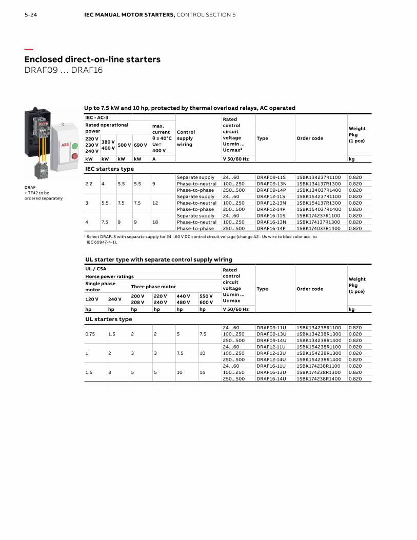
—Enclosed direct-on-line startersDRAF09 … DRAF16
Up to 7.5 kW and 10 hp, protected by thermal overload relays, AC operated
IEC - AC-3
Control supply wiring
Rated control circuit voltageUc min ... Uc max¹
Type Order code
WeightPkg(1 pce)
Rated operationalpower
max. currentθ ≤ 40°CUe= 400 V
220 V230 V240 V
380 V 400 V
500 V 690 V
kW kW kW kW A V 50/60 Hz kg
IEC starters type
2.2 4 5.5 5.5 9Separate supply 24…60 DRAF09-11S 1SBK134237R1100 0.820Phase-to-neutral 100...250 DRAF09-13N 1SBK134137R1300 0.820Phase-to-phase 250...500 DRAF09-14P 1SBK134037R1400 0.820
3 5.5 7.5 7.5 12Separate supply 24…60 DRAF12-11S 1SBK154237R1100 0.820Phase-to-neutral 100...250 DRAF12-13N 1SBK154137R1300 0.820Phase-to-phase 250...500 DRAF12-14P 1SBK154037R1400 0.820
4 7.5 9 9 18Separate supply 24…60 DRAF16-11S 1SBK174237R1100 0.820Phase-to-neutral 100...250 DRAF16-13N 1SBK174137R1300 0.820Phase-to-phase 250...500 DRAF16-14P 1SBK174037R1400 0.820
¹ Select DRAF..S with separate supply for 24...60 V DC control circuit voltage (change A2 - Us wire to blue color acc. to IEC 60947-4-1).
DRAF+ TF42 to be ordered separately
UL starter type with separate control supply wiringUL / CSA Rated
control circuit voltageUc min ... Uc max
Type Order code
WeightPkg(1 pce)
Horse power ratingsSingle phase motor
Three phase motor
120 V 240 V200 V 208 V
220 V 240 V
440 V 480 V
550 V 600 V
hp hp hp hp hp hp V 50/60 Hz kg
UL starters type
0.75 1.5 2 2 5 7.524…60 DRAF09-11U 1SBK134238R1100 0.820100...250 DRAF09-13U 1SBK134238R1300 0.820250...500 DRAF09-14U 1SBK134238R1400 0.820
1 2 3 3 7.5 1024…60 DRAF12-11U 1SBK154238R1100 0.820100...250 DRAF12-13U 1SBK154238R1300 0.820250...500 DRAF12-14U 1SBK154238R1400 0.820
1.5 3 5 5 10 1524…60 DRAF16-11U 1SBK174238R1100 0.820100...250 DRAF16-13U 1SBK174238R1300 0.820250...500 DRAF16-14U 1SBK174238R1400 0.820

5-25IEC MANUAL MOTOR STARTERS, CONTROL SECTION 5
—Enclosed direct-on-line startersDRAF09 … DRAF16
Up to 7.5 kW and 10 hp, protected by thermal overload relays, AC operated - continued
TF42 thermal overload relays to be ordered separately
Setting range Short-circuit protective device
Trip class Type Order codeWeight(1 pce)
A kg0.10 ... 0.13 0.5 A, Fuse type T 10 TF42-0.13 1SAZ721201R1005 0.1300.13 ... 0.17 1.0 A, Fuse type T 10 TF42-0.17 1SAZ721201R1008 0.1300.17 ... 0.23 1.0 A, Fuse type T 10 TF42-0.23 1SAZ721201R1009 0.1300.23 ... 0.31 1.0 A, Fuse type T 10 TF42-0.31 1SAZ721201R1013 0.1300.31 ... 0.41 2.0 A, Fuse type gG 10 TF42-0.41 1SAZ721201R1014 0.1300.41 ... 0.55 2.0 A, Fuse type gG 10 TF42-0.55 1SAZ721201R1017 0.1300.55 ... 0.74 4.0 A, Fuse type gG 10 TF42-0.74 1SAZ721201R1021 0.1300.74 ... 1.00 6.0 A, Fuse type gG 10 TF42-1.0 1SAZ721201R1023 0.1301.00 ... 1.30 6.0 A, Fuse type gG 10 TF42-1.3 1SAZ721201R1025 0.1301.30 ... 1.70 10.0 A, Fuse type gG 10 TF42-1.7 1SAZ721201R1028 0.1301.70 ... 2.30 10.0 A, Fuse type gG 10 TF42-2.3 1SAZ721201R1031 0.1302.30 ... 3.10 10.0 A, Fuse type gG 10 TF42-3.1 1SAZ721201R1033 0.1303.10 ... 4.20 20.0 A, Fuse type gG 10 TF42-4.2 1SAZ721201R1035 0.1304.20 ... 5.70 20.0 A, Fuse type gG 10 TF42-5.7 1SAZ721201R1038 0.1305.70 ... 7.60 35.0 A, Fuse type gG 10 TF42-7.6 1SAZ721201R1040 0.1307.60 ... 10.0 35.0 A, Fuse type gG 10 TF42-10 1SAZ721201R1043 0.13010.0 ... 13.0 40.0 A, Fuse type gG 10 TF42-13 1SAZ721201R1045 0.13013.0 ... 16.0 40.0 A, Fuse type gG 10 TF42-16 1SAZ721201R1047 0.13016.0 ... 20.0 63.0 A, Fuse type gG 10 TF42-20 1SAZ721201R1049 0.145
Empty enclosure with push-buttonmm cable inlet/outlet suitable for IEC starter types – FR16AF-12 1SBN101337R1000 0.53Inch cable inlet/outlet suitable for UL starter types – FR16AF-12U 1SBN101338R1000 0.53
To be completed with AF contactor, TF42 thermal overload relay and CB5-10 (1SBN010013R1010) start contact block.
TF42
Empty enclosurewith push-button

5-26 IEC MANUAL MOTOR STARTERS, CONTROL SECTION 5
Page 10-8
Direct-on-line starter
Rated operational current AC-53a
Rated operational powerAC-53a
Rated operational current AC-51
Setting range
Full load amps motor use
Type Order codeWeight(1 pce)
A kW A A A kg
Direct-on-line starter with overload protection0.6 0.18 (400V) 0.6 0.075 … 0.6 0.6 HF0.6-DOL-24VDC 1SAT112000R1011 0.2052.4 0.75 (400V) 2.4 0.18 … 2.4 2.4 HF2.4-DOL-24VDC 1SAT122000R1011 0.2186.5 3.00 (400V) 9.0 1.5 … 9.0 6.5 HF9-DOL-24VDC 1SAT142000R1011 0.206
Direct-on-line starter with overload protection and emergency stop0.6 0.18 (400V) 0.6 0.075 … 0.6 0.6 HF0.6-DOLE-24VDC 1SAT113000R1011 0.2052.4 0.75 (400V) 2.4 0.18 … 2.4 2.4 HF2.4-DOLE-24VDC 1SAT123000R1011 0.2186.5 3.00 (400V) 9.0 1.5 … 9.0 6.5 HF9-DOLE-24VDC 1SAT143000R1011 0.206
HF9-DOL-24VDC
—Electronic compact startersHF0.6, HF2.4, HF9
HF9-DOLE-24VDC

5-27IEC MANUAL MOTOR STARTERS, CONTROL SECTION 5
Reversing starter
Rated operational current AC-53a
Rated operational powerAC-53a
Rated operational current AC-51
Setting range
Full load amps motor use
Type Order codeWeight(1 pce)
A kW A A A kg
Reversing starter with no monitoring and no overload functionality6.5 3.00 (400V) 9.0 – 6.5 HF9-R-24VDC 1SAT144000R1011 0.174
Reversing starter with overload protection0.6 0.18 (400V) 0.6 0.075 … 0.6 0.6 HF0.6-ROL-24VDC 1SAT115000R1011 0.2172.4 0.75 (400V) 2.4 0.18 … 2.4 2.4 HF2.4-ROL-24VDC 1SAT125000R1011 0.2196.5 3.00 (400V) 9.0 1.5 … 9.0 6.5 HF9-ROL-24VDC 1SAT145000R1011 0.218
Reversing starter with overload protection and emergency stop0.6 0.18 (400V) 0.6 0.075 … 0.6 0.6 HF0.6-ROLE-24VDC 1SAT116000R1011 0.2182.4 0.75 (400V) 2.4 0.18 … 2.4 2.4 HF2.4-ROLE-24VDC 1SAT126000R1011 0.2706.5 3.00 (400V) 9.0 1.5 … 9.0 6.5 HF9-ROLE-24VDC 1SAT146000R1011 0.289
HF9-R-24VDC
HF9-ROL-24VDC
HF9-ROLE-24VDC
—Electronic compact startersHF0.6, HF2.4, HF9

5-28 IEC MANUAL MOTOR STARTERS, CONTROL SECTION 5
—Notes