1
Combustion process in high-speed diesel enginesConventional combustion characteristics
New combustion concept characteristics
Benefits and drawbacks
Carlo Beatrice Istituto Motori – CNR
The Requirements to the Modern Diesel Engine
V6 PSA engine
MARKET ENVIRONMENT
COST
PERFORMANCE
FUN TO DRIVE
EMISSIONS
FUEL CONSUMPTIONCustomer’s cost Low CO2 emiss.FULL
LO
AD
/SPE
ED C
ON
DIT
ION
S
NED
C P
RO
CED
UR
E
Carlo Beatrice, IM-CNR

2
4-Stroke DIESEL ENGINE CYCLE
DIESEL SPRAY STRUCTURE
Break up length
θ Cone angle
Sauter Mean Diameter and air/fuel mixing are affected by different spray parameters. The air/fuel mixing process strongly affects the engine fuel consumption and the pollutant emissions.
Final SMR: 5÷÷÷÷10µµµµm

3
-40 0 40Angoli di manovella dell'albero motore [°]
0
20
40
60Pr
essi
one
nel c
ilind
ro [b
ar]
0
0.5
1
1.5
2
2.5
Alz
ata
dello
spi
llo in
ietto
re [m
m]
0
100
200
300
Pres
sion
e di
man
data
del
la p
ompa
di i
niez
ione
[bar
]
P.M.S.Accensione della miscelaformatasi durante in tempodi ritardo all'accensione
Diesel engine cylinder pressure cycle
Tempo di ritardo all’accensione
Area di lavoro attivo
Ignition, flame evolution and soot formationIgnition, flame evolution and soot formationin a diesel sprayin a diesel spray
0 1 2 3 4 50
50
100
150 Injection duration
Time after injection (ms)
RO
HR
(J/m
s)
Source: Tokyo University

4
Visible combustion evolution in a DI diesel engine
Conventional diesel combustion
Source: Sandia National Laboratories
Classical Diesel Combustion Concept: in principle a non-stationary heterogeneous diffusive and partially premixed turbulent combustion
NOx controlled by:• flame temperature (Zel’dovichmechanism);• local N2 and O2 concentration
PM formation controlled by:• over-rich fuel concentration;• local O2 lack;• combustion temperature
Picture of a almost steady-state burning condition
Carlo Beatrice, IM-CNR

5
NOx formation background
NOx formation background

6
NOx formation backgroundIM: 1985 LD SC engine with FSV Daimler Benz: 2007 HD SC engine and CFD
simulation
NOx formation background
Source: Daimler Benz

7
DI Diesel engine combustion system design
Adequate spray penetration and fuelatomization control the optimum air/fuelmixing and then the final pollutantemissions.

8

9
NOx formation background
Source: Daimler Benz
Not for LD engine
NOx formation background
10
Source: Daimler Benz
Effectof EGR Rate on NOxReduction
HD Engine
Effectof OxygenConcentrationof IntakeAir on NOxFormation
Source: Daimler Benz
For different engine load there isthe same reduction rate for NOX vs O2 concentration

11
Decrease of local Gas Temperatures via EGR
In the photos the area with higher luminosity correspond to high sooting area at higher temperature
CFD simulation
Source: Daimler Benz
Decrease of local Gas Temperatures via EGRSource: Sandia Fuel: DGE, C6H14O3

12
Diesel combustion control
To assure the engine functionality an adequate control of SOC and combustion rate have to be realized.
Adequate Control of Adequate Control of AirAir--EGREGR--Fuel mixing Fuel mixing and of ignition delay and of ignition delay
timetime
BoostingBoosting
Intake Intake TemperatureTemperature
EGR Ratio (EGR Ratio (intint –– ext)ext)
Compression Compression RatioRatio
Thermal Thermal ConditionsConditions
Injection StrategyInjection Strategy
Combustion Combustion System System
ArchitectureArchitectureFuel Fuel
qualityquality
Control of:Control of:••CombComb. . NoiseNoise;;••Peak Peak pressurepressure;;••EfficiencyEfficiency;;••PollutantPollutant emissionsemissions
In every engine conditions there is an optimum Air/EGR Fuel mixing that realizes the better compromise among the output characteristics
Carlo Beatrice, IM-CNR
While for SI engines, the HCCI study is oriented to reduce both FC and NOx formation, for Diesel, the HCCI/PCCI research is oriented to exploit the very low simultaneous level of both PM and NOx, preserving the low Diesel BSFC.
Increased premixed level and EGR reduce local over-rich air/fuel ratio.
Source: SAE paper 2001-01-0655
New concepts combustion in diesel engines
Low Nox
Carlo Beatrice, IM-CNR

13
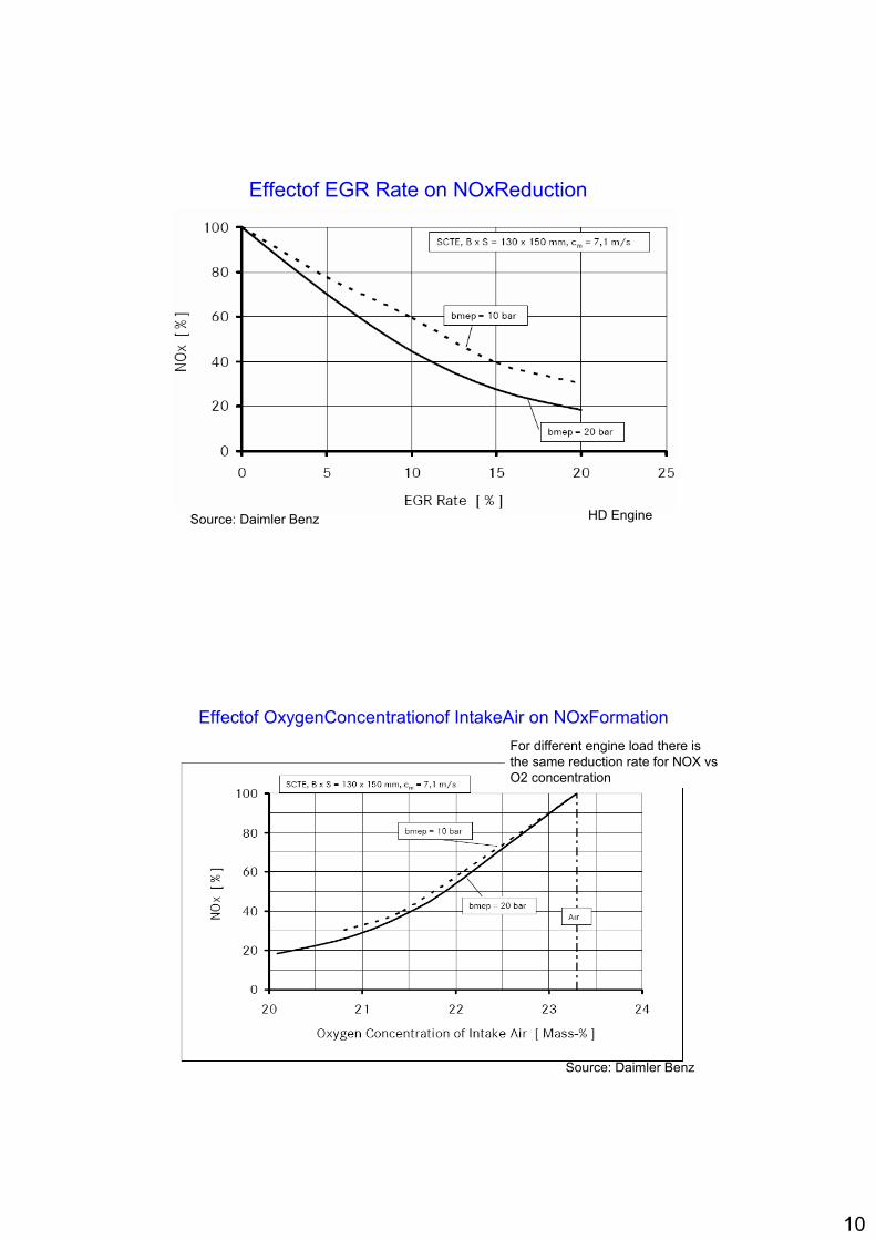
HCCI/PCCI combustion process
13° BTDC 12° BTDC 10° BTDC 8° BTDC9° BTDC 7° BTDC11° BTDC
3° BTDC TDC 4° ATDC 10° ATDC 15° ATDC 21° ATDC17° ATDC
Conventional Diesel Combustion
Nearly HCCI Combustion with diesel fuel in a LD DI Diesel engine
Source: Vaglieco et al., SAE paper 2007-01-0192
Carlo Beatrice, IM-CNR
Lowering flame temperature below a typical treshold reduces the soot formation.
Soot Yeld under pure pyrolisys vs Temperature
0
0.2
0.4
0.6
0.8
1
1700 1800 1900 2000 2100 2200
Temperature [K]
Soo
t Yel
d [a
.u.]
Tetradecane
Source: Beatrice et al., Comb. Sci. & Tech. 2001
Low Temperature Combustion regime
Carlo Beatrice, IM-CNR
HCCI/PCCI combustion process
14
Calculated NOx and soot formation rate vs φ-T map for the diesel combustion
Source: SAE paper 2001-01-0655
Carlo Beatrice, IM-CNR
HCCI/PCCI combustion process
When fuel burns under diesel combustion, fuel molecules are oxidated under different φ and T conditions
Source: SAE paper 2001-01-0655 Reduced NOx and Soot formationCarlo Beatrice, IM-CNR
HCCI/PCCI combustion characteristics

15
Source SAE Paper 2000-01-0331
HCCI for Diesel fuel can be approached with PFI or very Early injection strategies:
• PFI leads to very difficult control of global in-cylinder A/F, oil dilution by fuel, unburned HCs, SOC control and noise limitation;
•Early injection leads to same problems but less critical, depending on the combustion system and injection strategy.
•In both cases, due to the high boiling point of heavy fractions of the fuel, the homogenization is never reached.
Carlo Beatrice, IM-CNR
HCCI/PCCI combustion characteristics
HCCI Combustion approach for LD DI Diesel engines
Source MTZ
With conventional LD DI combustion systems the homogeneous approach is more and more stringent with heavy problems of knocking conditions
0
10
20
30
40
50
60
320 340 360 380 400 420 440Crank Angle [°]
Cyl
inde
r pre
ssur
e [b
ar]
-20
0
20
40
60
80
100
120
Rat
e of
Hea
t Rel
ease
[%/°
]
N-Heptane
1500 rpm @ 4.5 bar IMEP
Syngle-Cylinder LD DI Diesel engine
High knockingconditions
Carlo Beatrice, IM-CNR
16
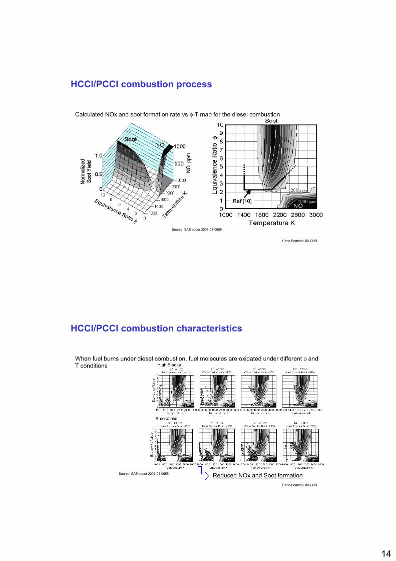
From HCCI to Premixed Low Temperature Combustion (PCCI/LTC)PCCI with diluted air/fuel charge by high EGR rate can be defined as the middle between HCCI and diesel combustion.They are characterized by almost premixed stratified Air/EGR/Fuel charge with a better link between injection event and SOC as in the diesel combustion.
Source: Neely et al., SAE Paper 2005-01-1091
1400 rpm @ 3 bar IMEP
0
10
20
30
40
50
60
70
-30 -20 -10 0 10 20 30 40 50 60C.A.[°]
CY
LIN
DE
R P
RE
SS
UR
E [b
ar]
.
-10
0
10
20
30
40
RO
HR
[%/°
]
Diesel fuel
SOImain = 11 BTDC
4-Cylinder LD DI diesel eninge
SOC after EOIControlled SOC
PCCI combustion is a “stratified highly diluted quasi-total premixed combustion”
Carlo Beatrice, IM-CNR
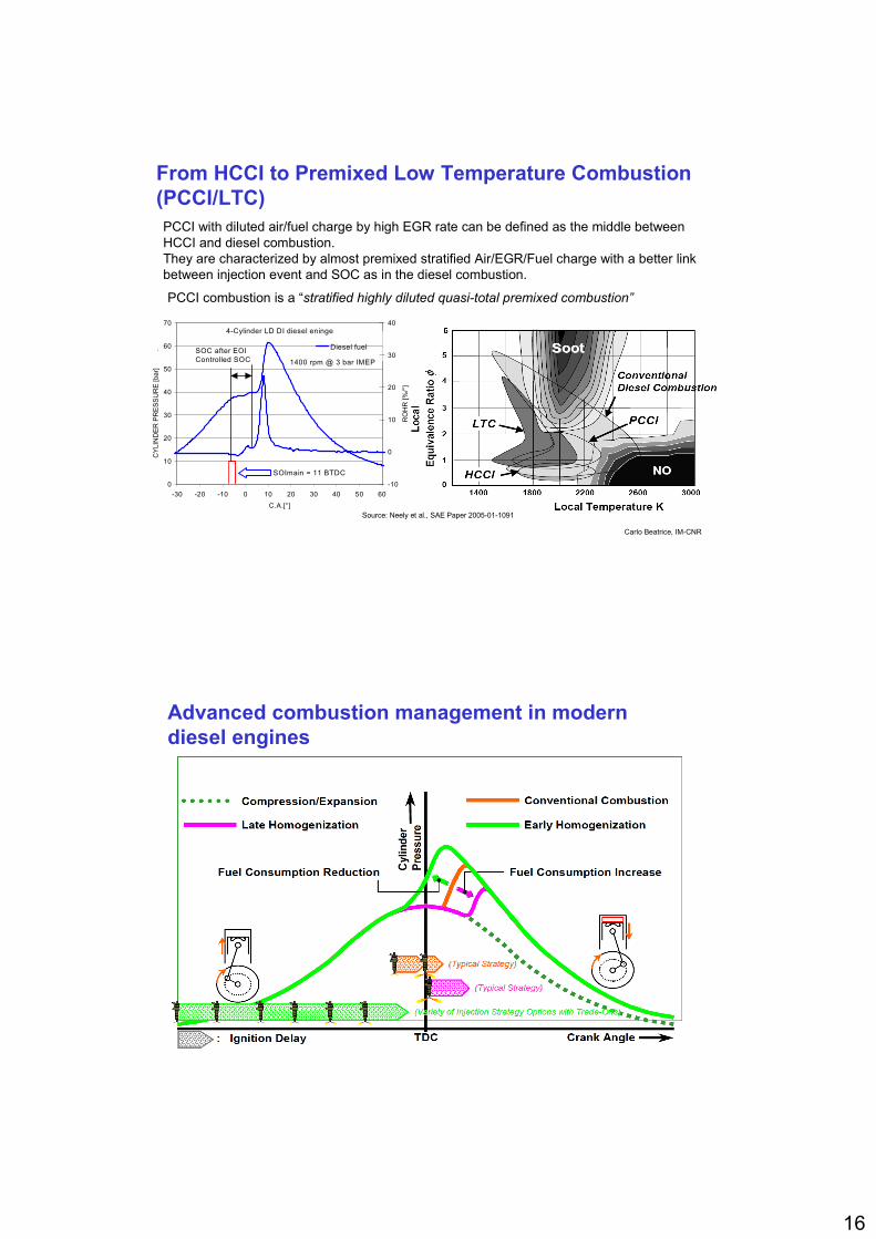
Advanced combustion management in modern diesel engines

17
PCCI vs Conventional Diesel Combustion
0
40
80
120
160
200
HC raw CO raw NOx raw BSFC
Emis
sion
Inde
xes
[%] Conventional Diesel
PCCI Combustion
1500 rpm @ 2 bar of BMEP
4-Cylinder LD DI Diesel engine
0
0.01
0.02
0.03
0.04
0.05
Smoke
Emis
sion
Inde
xes
[g/k
Wh]
Low Load with Early Injection Strategy
Carlo Beatrice, IM-CNR
PCCI vs Conventional Diesel Combustion
Medium Load with Late Injection Strategy
0
40
80
120
160
200
HC raw CO raw NOx raw BSFC
Em
issi
on In
dexe
s [%
] Conventional DieselPCCI Combustion
2000 rpm @ 5 bar of BMEP
4-Cylinder LD DI Diesel engine
0
0.03
0.06
0.09
0.12
Smoke
Emis
sion
Inde
xes
[g/k
Wh]
Carlo Beatrice, IM-CNR

18
Problems of PCCI application to DI Diesel engine
Few problems at low load. Heavy problems at medium high load:
• SOC control;
• pollutants;
• FC;
• engine durability;
• cylinder to cylinder balancement;
• transient engine control;
NOx;HCs;CO;PM.
adequate EGR distrb.impingmentoverleaning
low comb. temp.quenching
low O2 local conc.
η thermod.η comb.
Fouling componentsmech. stress (knocking)oil dilution
cylind. to cylind. EGR distrib.cylind. to cylind. thermal cond.
response of combustion to all above factors durnigtransient conditions
Carlo Beatrice, IM-CNR
KIVACFD Computations
Fuel Injection
Initial Conditions
Fuel evaporationBreakup models
Ignition delay+
Combustion Model
Detailedkinetics
solver and time step
locallychosen
KIVA
3V_R
el2
MultimethodMultimethodsolverssolvers
DVODEDVODE /SDIRK/SDIRK
Combustion ModelCHEMKIN 3.1CHEMKIN 3.1
Numerical Solvers
Conventionalcombustionapplication
reaction scheme:
44 species and 112 reactions
for n-heptane

19
• The continuous dimensional distribution function isdiscretized into classes of fixed molecular weight
ParticlesParticles formationformation modelingmodeling –– sectional approach
• In the earlier stages of the engine combustion number weighted particle distribution is mono-modal• With the progress of combustion the size distributions change from monomodal into bi-modal: after 12 CAD, first mode corresponds to particles smaller than 3nm and second mode to a peak between 30 and 60 nm.
D’Anna, A., Detailed kinetic modeling of Particulate Formation in Rich Premixed Flames of Ethylene, Energy Fuels 22, 2008
Advanced technologies to realize practical application of HCCI combustion: Combustion System Architecture
To increase premixing level, reducing unburned compounds, reducing cylinder wall wetting (oil dilution) and extend the HCCI application, an accurate combustion system design is needed
ReducedCR
low smoke;≈ FC;≈NOx;High CO, HCs;
extension of PCCI application area
NADI TM system (IFP)
Carlo Beatrice, IM-CNR

20
Advanced technologies to realize practical application of HCCI combustion: EGR
EGR is the main driver for NOx control
Source: Imarisio et al., ATA congress, Siracusa 2006
The use of an advanced EGR layout with LP+HP EGR can extend the engine tolerability to the high EGR rate increasing the HCCI application area at medium load
Carlo Beatrice, IM-CNR
Advanced technologies to realize practical application of HCCI combustion: Advanced Injection Systems
To improve the premixed Air/EGR/Fuel charge inside the cylinder, to employ injection system with injection rate shaping will be useful.
Source: Imarisio et al., ATA congress, Siracusa 2006
Improved solenoid injectoror
Piezo injector
time
Inje
ctio
nflo
wra
te
first flat slope
final high flow rate
Source: Hammer (BOSCH), ATA congress, Bari 2004
low impingment;low oil dilution;low overleaning.
fuel distrib. control;comb. rate control.
Source: Gastaldi et al. (RENAULT), ATA congress, Siracusa 2006
Carlo Beatrice, IM-CNR

21
Advanced technologies to realize practical application of HCCI combustion: Advanced Air Layout Systems 2
exhaust stroke
re-opening exhaust valve during intake stroke
cam angle
valv
e lif
t
VVA system can be a very useful tool to control the in-cylinder temperature during the warm up in the NEDC.
Source: Lisbona et al., TDCE congress, Ischia 2007
Carlo Beatrice, IM-CNR
Advanced technologies to realize practical application of HCCI combustion: Closed Loop Combustion Control
PCCI applicationin a veichle withclosed loopcomb. control
Closed Loop Comb. Control is the prerequisite for SOC control and EGR effectsSource: Lisbona et al., TDCE congress, Ischia 2007
Source: Hűlser et al., SAE paper 2006-01-1146
Carlo Beatrice, IM-CNR

22
THE FUTURE HCCI DI CI engines
The correct development and application of all technologies will help to bring the LD DI engines to match the future stringent emission regulation preserving the fuel consumption, fun to drive and performance at full load.
The improvement ok knowledge in the HCCI combustion characteristics is fundamental to define the line-guides for HCCI combustion control technologies.
The practical application of HCCI to the real CI engines will depend on the acquisition of the necessary knowledge to control the desiderate characteristics of the air/EGR/fuel charge inside the cylinder before the start of the combustion.
Carlo Beatrice, IM-CNR