Nalcor Energy - Lower Churchill Project
) nalcorenergy
LOWER CHURCHILL PROJECT
SOBI Marine Crossing "Phase 2" Conceptual Design
ILK-PT-ED-8110-M R-RP-0001-O1
Comments: Total # of Pages
___________ (Including Cover):494
Bi / Issued For Use .Tr-__7 /777
__________
I 3'dl.oft S. Driscol i1adden T. Ralph B. Bug G. Flemi P. HrrgtcV
Status/ Date Reason For Issue Prepared By Checked By Checked By Checked By Dept. Manager ProjectRevision I Approval Manager
Aoproval
This document contains intellectual property of the Nalcor Energy - Lower Churchill Project and shall not be copied,bNFIDENTIALITV NOTE: used or distributed in whole or in part without the prior written consent from the Nalcor Energy - Lower Churchih
__Project.
__- ____ _ __
Muskrat Falls Project - CE-44 Rev. 2 (Public) Page 1 of 333
SOBI Marine Crossing "Phase 2" Conceptual Design ILK-PT-ED-8110-MR-RP-0001-O1Rev. B
(
Professional Engineers Stamp:(where required)
Form #: LCP 1T ED-0000 IM FR 0002-01 Rev. Al
Muskrat Falls Project - CE-44 Rev. 2 (Public) Page 2 of 333

Table of Contents
Acronym list .................................................................................................................. 4
1.0 STRAIT OF BELLE ISLE CROSSING ...................................................................... 5
1.1 Background ................................................................................................................ 5 1.2 Scope of Work ............................................................................................................ 7
2.0 Conceptual Design Solution................................................................................... 8 3.0 Feasibility Analysis and Approach ...................................................................... 11
3.1 Documentation Review.............................................................................................12 3.2 Routing ......................................................................................................................13 3.3 Cables ........................................................................................................................15
3.3.1 ABB High Voltage Cables ................................................................................................... 15 3.3.2 Nexans Norway AS ............................................................................................................. 16 3.3.3 Prysmian Powerlink ............................................................................................................. 17
3.4 Transition Compounds .............................................................................................17 3.5 Insulation Types and Conversion Technology .......................................................18 3.6 Integrated Fiber Optic Cable Installation.................................................................18 3.7 Burial Depth of Cables in HDD Boreholes ...............................................................18 3.8 External Influences ...................................................................................................18
3.8.1 Icebergs ............................................................................................................................... 19 3.8.2 Sea Currents ....................................................................................................................... 19 3.8.3 Vessel Traffic ....................................................................................................................... 20 3.8.4 Fishing Gear ........................................................................................................................ 20
3.9 Protection Methods ..................................................................................................20 3.9.1 Horizontal Directional Drilling (HDD) Landfall ..................................................................... 20 3.9.2 Rock Placement .................................................................................................................. 21 3.9.3 Trenching ............................................................................................................................ 21 3.9.4 Trenched Landfall................................................................................................................ 22 3.9.5 Shore-based Tunnel with Seafloor Piercing Landfall .......................................................... 23 3.9.6 Micro-Tunneling Landfall ..................................................................................................... 24 3.9.7 Other Local Protection Technologies .................................................................................. 24
3.10 Installation and Marine Operations ......................................................................24 3.10.1 Cable Installation Vessels ................................................................................................... 25 3.10.2 Other Intervention Vessels .................................................................................................. 26 3.10.3 Transportation ..................................................................................................................... 27 3.10.4 Inspection, Repair, Maintenance (IRM) .............................................................................. 27
3.10.4.1 Inspection .................................................................................................................... 27 3.10.4.2 Repair .......................................................................................................................... 27
4.0 Qualitative Risks ................................................................................................... 29
5.0 Commitments and Construction Schedule ......................................................... 30
6.0 Capital Cost ........................................................................................................... 31
Muskrat Falls Project - CE-44 Rev. 2 (Public) Page 3 of 333

7.0 Operating Cost ...................................................................................................... 32
8.0 Repair Cost ............................................................................................................ 32
9.0 Spending Profile .................................................................................................... 33
Muskrat Falls Project - CE-44 Rev. 2 (Public) Page 4 of 333
Appendices Appendix A – Proposed Seabed Crossing Route
Appendix B – Work Scopes 2010
Appendix C – Gap Registry
Appendix D – ABB Cable Cost
Appendix E – Nexans HDD Pulling Tension Confirmation
Appendix F – Nexans Cable Cost
Appendix G – Nexans MI Cross Sectional Breakdown
Appendix H – Prysmian Pulling Tension
Appendix I – Prysmian Study Results
Appendix J – Cu and Al Budgetary Costs
Appendix K – Vessel Traffic
Appendix L – Fishing Gear
Appendix M – HDD Feasibility Report
Appendix N – RT-1 and Assotrencher IV
Appendix O – Shore Based Tunnel to Seabed Techniques
Appendix P – Pro Dive Solutions
Appendix Q – COPS Report
Appendix R – AHMTEC Cable Protection System
Appendix S – Vos Product Innovation
Appendix T – Serpent Cable Flotation System
Appendix U – Cable Laying Vessel Specifications
Appendix V – Skagerrak Information
Appendix W – Scanmudring SCANmaskin Information
Appendix X – Cutting Grapnel
Appendix Y – Nexans Skagerrak Cable Repair Specifications
Appendix Z – SOBI Seabed Installation Schedule
Appendix AA – Cost Estimate
Appendix AB – Repair Cost
Appendix AC – Westney Risk Report
Muskrat Falls Project - CE-44 Rev. 2 (Public) Page 5 of 333

Acronym list
CAD Canadian Dollars CIV Cable Installation Vessel COPS Continuous Operating Protection System DCC Document Control Center DP Dynamic Positioning EA Environmental Assessment EIS Environmental Impact Statement EPC Engineering, Procurement, Construction FEED Front End Engineering Design GVI General Visual Inspection GPS Global Positioning System HDD Horizontal Directional Drilling HDPE High Density Polyethylene HIRA Hazard Identification Risk Assessment HMM Hatch-Mott Macdonald HVDC High Voltage Direct Current IRM Inspection, Repair And Maintenance ITP Inspection Testing Plan LCC Line Commutated Conversion LCP Lower Churchill Project MI Mass Impregnated NDA Non-Disclosure Agreement NE-LCP Nalcor Energy - Lower Churchill Project NPT Non-Productive Time NPV Net Present Value PM&E Project Management & Engineering ROV Remote Operated Vehicle SOBI Strait Of Belle Isle TBM Tunnel Boring Machine TDR Time Domain Reflectometry UCS Uniaxial Compressive Strength VSC Voltage Source Converter WOW Waiting On Weather WTO Work Task Order XLPE Cross Linked Polyethylene
Muskrat Falls Project - CE-44 Rev. 2 (Public) Page 6 of 333

1.0 STRAIT OF BELLE ISLE CROSSING
1.1 Background
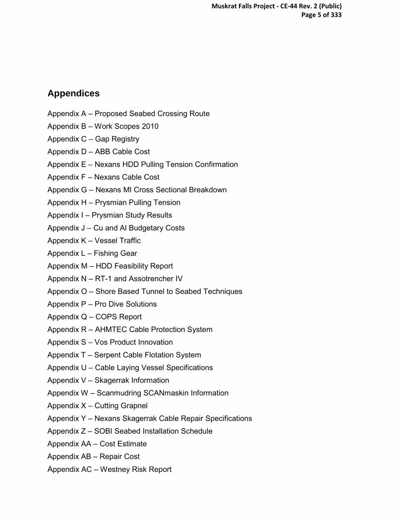
Nalcor Energy is headquartered in St. John’s, NL, Canada. Its business includes the development, generation, transmission and sale of electricity; the exploration, development, production and sale of oil and gas; industrial fabrication and energy marketing. Focused on sustainable growth, the company is leading the development of the province’s energy resources and has a corporate-wide framework which facilitates the prudent management of its assets while continuing an unwavering focus on the safety of its workers and the public. Nalcor currently has five lines of business: Newfoundland and Labrador Hydro, Churchill Falls, Oil and Gas, Lower Churchill Project and Bull Arm Fabrication. The Churchill River, located in the Province of Newfoundland and Labrador, Canada, is a significant source of renewable, clean electrical energy; however, the potential of this river has yet to be fully developed. The existing 5,428 megawatt (MW) Churchill Falls Generating Station, which began producing power in 1971, harnesses about 65 percent of the potential generating capacity of the River. The remaining 35 percent is planned to be developed via two sites on the lower Churchill River, known as the Lower Churchill Project. The Project includes two undeveloped hydroelectric sites and associated transmission systems, specifically the Lower Churchill Hydroelectric Generation Project (Generation Project) and Labrador – Island Transmission Link (Transmission Project). The Generation Project consists of proposed generating facilities at two sites in on the lower Churchill River in Central Labrador- a 2250 MW facility at Gull Island and an 824 MW facility at Muskrat Falls. The Labrador – Island Transmission Link is a proposed 1,100km High Voltage direct current (HVdc) transmission line connecting Central Labrador with the island of Newfoundland’s Avalon Peninsula. In November 2010, Nalcor Energy entered a Partnership with Emera Inc. to develop phase one of the Lower Churchill Project. This development includes the Muskrat Falls generating facility, the Labrador – Island Transmission Link and an additional transmission line, the Maritime Transmission Link, connecting the island of Newfoundland and nei ghboring province, Nova Scotia. Phase one of the Project is valued at $6.2 billion.
Muskrat Falls Project - CE-44 Rev. 2 (Public) Page 7 of 333
Figure 1 - Schematic Depiction of the HVdc Route
Muskrat Falls Project - CE-44 Rev. 2 (Public) Page 8 of 333

1.2 Scope of Work
With reference to the Lower Churchill Project Gateway Process LCP-PT-MD-0000-PM-0001-01 (refer to Figure 2), the SOBI seabed crossing conceptual design is required prior to moving into Phase 3.
The scope of work during Phase 2 i nvolved development of a t echnically feasible solution for extending the HVdc transmission system across the SOBI. It has been determined that the seabed crossing would have cables placed on or beneath the seafloor. A SOBI Crossing Team Charter was established to outline the purpose, objectives, success factors, and roles for execution of the work. A specialized team was mobilized and technical feasibility analyses were undertaken to develop a c onceptual design to meet the charter objectives. The results of the feasibility analyses, including the finalized conceptual design are described hereafter.
Figure 2 - Gateway Process
Muskrat Falls Project - CE-44 Rev. 2 (Public) Page 9 of 333

2.0 Conceptual Design Solution
The following sections detail the process for the cable installation on a conceptual design basis and include:
Routing
The cable corridor in which the conceptual cable route is to be defined is as shown in Figure 3. This corridor takes into account the landfall and protection methods discussed in this report. The estimated length is approximately 36 km with roughly 32 km on the sea floor. The route is depicted within a 500 m wide corridor with a 1500 m diameter circular seafloor piercing target zone for HDD. Detailed cable spacing and routing will be carried out in phase 3
Figure 3 Conceptual Cable Corridor
Cables
The current conceptual cable design includes:
• Single Core (Copper or Aluminum conductor, pending detailed design)
Muskrat Falls Project - CE-44 Rev. 2 (Public) Page 10 of 333

• Mass impregnated paper insulated cables
• Double wire armor (DWA) in a counter-helical fashion to maximize pulling tension and provide rock armoring. Armor will consist of steel wire coated in Bitumen.
• Outer serving will consist of two layers of polypropylene yarn or high density polyethelyne as needed.
• Cables will each be rated to carry 450 MW at 320 kV.
The LCP preliminary cable design for the Strait of Belle Isle is within the limits of previous cable designs. While incorporating long-term field proven technology only. The cables for the 900 MW – 320 kV case could either be Mass Impregnated (MI) or Cross-linked Polyethylene (XLPE), with the former being the lowest risk design at this time due to the extensive global in-service track record. XLPE has been type tested at 320 kV, however the first 320 kV cable has not yet been installed. Long term aging tests have been completed as part of the type testing, but there is no significant field service data for 150 kV XLPE and above.
Transition Compounds and Terminations
At each side of the crossing, all three cables will terminate at a Transition Compound, to be designed, supplied, and constructed by the EPCM contractor. It is envisaged at this time that the cables will be pulled to shore then land trenched to the location of the transition compound. The compound location is not yet defined but will most likely be located 150 m to 1000 m from each shoreline. The compound will house the cable terminations, as well as any switch gear that is required for system operation. Actual footprint and height of the compounds will be determined by the EPCM and are based on isolation requirements and installation techniques of the terminations. The cables will enter the transition compound through a foundation penetration.
End terminations for each cable will reside inside the Transition Compound, and will be inclusive of the stand, insulator, and ancillary equipment. All equipment associated with the end termination will be supplied and installed as part of the cable supply contract.
Landfall - HDD
For both shore approaches, Horizontal Directional Drilling (HDD) will be ut ilized to protect the cables and will run from the shore to a p oint on the seafloor within the designated piercing target zone. This point will be approximately 2 km from the shoreline, however may become shorter or longer pending detailed design. The HDD solution will p rovide steel-lined boreholes for each shore approach. A footprint of approximately 2-6 acres is required on both Newfoundland and Labr ador sides of the Strait to execute the HDD scope.
Cable Installation
Muskrat Falls Project - CE-44 Rev. 2 (Public) Page 11 of 333

The current philosophy is that the cable installation will include a subsea joint to allow for pull-in without laying an over length on the seafloor. The sequence for each current cable installation is as follows:
• Pull-in side 1 • Normal lay • Abandon • Pull-in side 2 • Normal lay • Recover side 1 • Join • Abandon
Deepwater Zones – Rock Placement
For the deepwater zones Rock Placement will be utilized to protect the cables between the HDD seafloor piercing on the Newfoundland side and the HDD seafloor piercing on the Labrador side. Each cable will be protected by a dedicated rock berm, which will be 0.5 - 1.5 m high with the potential for higher regions if additional protection is required. Preliminary studies suggest that the rock berm will have a nominal side slope ratio of 1:4 (rise:run) and will be 8-12 m wide at the base. The current rock has been based on a 8” D minus (maximum graded target size will be 8 inch diameter).
Muskrat Falls Project - CE-44 Rev. 2 (Public) Page 12 of 333

External InfluencesExternal
Influences
ReportTechnical, Cost,
Schedule, Risk, Go Forward Plan
Early and Continuous Supplementary Work Identification
Previous Documentation
Review
Cable(s) /Transmission
Definition
SOBI Route
Analysis
Installation
Methodology
Protection
Methodology
DELIVERABLE
ReportTechnical, Cost,
Schedule, Risk, Go Forward Plan
Early and Continuous Supplementary Work Identification
Previous Documentation
Review
Cable(s) /Transmission
Definition
SOBI Route
Analysis
Installation
Methodology
Protection
Methodology
ReportTechnical, Cost,
Schedule, Risk, Go Forward Plan
Early and Continuous Supplementary Work Identification
Previous Documentation
Review
Cable(s) /Transmission
Definition
SOBI Route
Analysis
Installation
Methodology
Protection
Methodology
Early and Continuous Supplementary Work Identification
Previous Documentation
Review
Cable(s) /Transmission
Definition
SOBI Route
Analysis
Installation
Methodology
Protection
Methodology
Previous Documentation
Review
Cable(s) /Transmission
Definition
SOBI Route
Analysis
Installation
Methodology
Protection
Methodology
DELIVERABLE
MAR APRIL MAY JUNE JULY AUGUST SEPTEMBER OCTOBER NOVEMBER DEC
ReportTechnical, Cost,
Schedule, Risk, Go Forward Plan
Early and Continuous Supplementary Work Identification
Previous Documentation
Review
Cable(s) /Transmission
Definition
SOBI Route
Analysis
Installation
Methodology
Protection
Methodology
DELIVERABLE
ReportTechnical, Cost,
Schedule, Risk, Go Forward Plan
Early and Continuous Supplementary Work Identification
Previous Documentation
Review
Cable(s) /Transmission
Definition
SOBI Route
Analysis
Installation
Methodology
Protection
Methodology
ReportTechnical, Cost,
Schedule, Risk, Go Forward Plan
Early and Continuous Supplementary Work Identification
Previous Documentation
Review
Cable(s) /Transmission
Definition
SOBI Route
Analysis
Installation
Methodology
Protection
Methodology
Early and Continuous Supplementary Work Identification
Previous Documentation
Review
Cable(s) /Transmission
Definition
SOBI Route
Analysis
Installation
Methodology
Protection
Methodology
Previous Documentation
Review
Cable(s) /Transmission
Definition
SOBI Route
Analysis
Installation
Methodology
Protection
Methodology
DELIVERABLE
3.0 Feasibility Analysis and Approach
As of Q1 2010, a team was mobilized to progress feasibility of seabed cable installation with a target to complete a conceptual design by late Q4 2010. The following schematic outlines the process flow implemented by the team and timing for the feasibility study.
Figure 3 - Feasibility Study Execution Plan
Muskrat Falls Project - CE-44 Rev. 2 (Public) Page 13 of 333

The following is a summary of the schedule that was developed to progress the work. The detailed schedule is included in Appendix B.
Figure 3 - Seabed Feasibility Summary Schedule
3.1 Documentation Review
A comprehensive documentation review was undertaken to understand all value added work completed prior to 2010. T he scope involved reviewing all studies, reports, and project material for the past four decades. The objective was to identify all useful information that could be obt ained from past studies, and i dentify gaps in the information. These gaps and oppor tunities were then incorporated into each of the individual sub-scopes for the HVdc cable crossing of the Strait of Belle Isle.
Through the course of the two month review, more than 100 reports, 70 drawings and maps, and 120 p resentations were reviewed and assesed. A n information and gap register was developed with over 850 l ine items for incorporation into the sub-scopes. This register is included in Appendix C.
Muskrat Falls Project - CE-44 Rev. 2 (Public) Page 14 of 333

3.2 Routing
The Strait of Belle Isle seabed crossing, although merely some 18 km from shore to shore, is extremely complex and pos es numerous challenges for installation and protection that include sea currents, icebergs, pack-ice, tidal forces, hard rock sea bottom, varying water depths, fishing activities, and vessel traffic. Prior to the current task force’s engagement to engineer a solution, two 0.5 km wide seafloor corridors were selected by a pr evious consultant, in cooperation with Nalcor Energy. T his work was carried out in 2007. These routes have been cited as part of the environment assessment process. To minimize impact on the overall project schedule and pr event any environmental related re-work, the mandate of the team was to adhere to portions of the previously selected routing where technically feasible.
Analysis of various external influences and p rotection methods demonstrate that a portion of the easterly route selected in 2007 potentially poses a high level of risk and is, on a go-forward basis, not considered to be feasible for a seabed crossing unless there are new developments in iceberg risk compensation This is primarily applicable to the shelf area on the Labrador side that is located in an ar ea of a higher risk for iceberg scour than the deep channel portion of the western corridor. In view of the above, the western corridor, combined with some portions of the easterly corridor, is preferred for the conceptual design seabed crossing route. Due to the ability to achieve deeper water in less distance from shore, an alternate route to Shoal Cove has been considered as the base case and w ill be carried forward in the environmental assessment process (refer to Appendix A)
To develop an adequate solution for the entire westerly corridor combined with portions of the easterly corridor, a zone approach was implemented. The route was divided into the following zones (refer to Figure 4):
• Labrador Landfall (Zone 1) – This zone starts on land that is nominally 150 to 1000 m from the shoreline, and extends to a water depth between 65 and 85 meters, near the Deepwater Channel. Protection in this zone is primarily required for tidal, pack ice, icebergs, and fishing.
• Deepwater Channel (Zone 2) – A nominally 400 – 750 m wide deepwater channel that starts on the Labrador side and runs to approximately the midpoint on the route. Protection in this zone is primarily required for vessel traffic (dropped objects) and fishing.
• Eastern Corridor (Zone 3) – A region of nominally 65 - 75 m water depth that runs from the Labrador Landfall to the Deepwater Basin. Protection in this zone is primarily required for vessel traffic and fishing and has a higher probability of iceberg scour.
• Deepwater Basin (Zone 4) – A region of nominally 100 to 120 m water depth that runs from Deepwater Channel to the Newfoundland landfall in both corridors. Protection in this zone is primarily required for vessel traffic (dropped objects) and fishing.
Muskrat Falls Project - CE-44 Rev. 2 (Public) Page 15 of 333

• Newfoundland Shore Approach (Zone 5) – This zone that is nominally 150 to 1000 m from the shoreline, and extends to a water depth between 65 and 85 meters. Protection in this zone is primarily required for tidal, pack ice, icebergs, and fishing.
These zones are depicted in the following schematic.
Figure 4 - Subsea Corridor Zones
Upon review of the current work status for the sub-scopes as detailed in Section 3.0, and owing to deliverables and indicators received as of December 2010 as described in that section, it was determined that the following is the recommended solution for the SOBI seabed crossing. The cable routing is as shown in Figure 3. This route takes into account the landfall and pr otection methods discussed in this report. The estimated length is approximately 36 km with roughly 32 km on the sea floor. The route is depicted as a 500 m wide corridor with a 1500 m diameter circular seafloor piercing target zone. Detailed cable spacing and routing will be carried out in phase 3 with a recommendation that a no fish zone be established.
Labrador Shore Approach (Zone 1)
Deep Water Channel (Zone 2)
Eastern Corridor (Zone 3)
Deep Water Basin (Zone 4)
Newfoundland Shore Approach (Zone 5)
Muskrat Falls Project - CE-44 Rev. 2 (Public) Page 16 of 333

This solution is feasible from a technical and schedule perspective. Developments and further engineering may result in a change in design through Phase 3.
The following sections outline the work performed for each component of the study execution plan. For all sub-scopes a work task order (WTO), a separate contract, or an internal research task was implemented.
3.3 Cables
An assessment of HVdc cable technologies to meet the transmission parameters, as outlined in the design basis, was commenced early Q2 2010. Extensive research into the cable industry in general, and more specifically, cable suppliers and relevant projects was carried out to gain an understanding of HVdc cables. Of the global cable manufacturers, ABB, Nexans, and Prysmian were selected as candidates for conceptual study work as they are the three leading HVdc cable manufacturers in volume and technology and have the proven track record when it comes to large-scale HVdc projects. These three vendors have all indicated that the solution definition as defined above is feasible for the SOBI.
To further establish the feasibility of existing cable technologies for SOBI conditions, a scope of work was developed to be issued to cable manufacturers for development of a conceptual level design. The scope of work issued included a comprehensive suite of input parameters. Each supplier was asked to perform preliminary design calculations and feasibility work, as well as to provide a cable recommendation for the SOBI criteria. Output specifications were requested and were to include all parameters pertinent to transmission, installation, protection, inspection, repair and maintenance.
3.3.1 ABB High Voltage Cables
The scope of work was issued to ABB on July 5th and ABB has since reverted with a detailed proposal. The proposal has been reviewed and accepted by Nalcor. A service agreement has been established and work will be completed by ABB in Phase 3.
To acquire information required for the SOBI decision, a site visit was carried out with ABB on August 24th in Karlskrona, Sweden at their engineering and fabrication facility. Meetings held included extensive details on design, supply, and installation for the project with ABB key personnel.
Of the three cable types being considered in the scope of work, ABB has indicated that oil-filled is not a viable option. Oil-filled cables carry the inherent environmental risk in the case of damage, and are considerably more complicated and expensive to produce.
Mass impregnated cables will be detailed in the scope of work and ABB will carry out appropriate design development where required. Mass impregnated cables can meet the transmission requirement established for the project, and the acceptable level of reliability for the link. Mechanical, electrical, and thermal specifications for mass impregnated cables meet the requirements as established in the solution definition for seabed cable installation. ABB has an excellent cable manufacturing track record, with
Muskrat Falls Project - CE-44 Rev. 2 (Public) Page 17 of 333

no reported failures due to manufacturing defects for protected cables. Budgetary costs are included in Appendix D.
Cross-linked polyethylene (XLPE) insulated cable design will also be dev eloped on a conceptual level for the SOBI crossing. ABB has recommended XLPE as they favor the technology from both a manufacturing and installation perspective. Type testing has been completed for 320 kV, which included 1 year long term aging tests. XLPE cables at this voltage have not yet been installed; however budgetary costs are included in Appendix D (Same as above).
ABB has indicated that the installation of HVdc cables in the Strait of Belle Isle is feasible according to the solution definition and installation criteria including HDD pull-in.
ABB has indicated that a 2-3 year booking lead time for a factory slot is necessary to ensure timely delivery of cable product. This is subject to market conditions and is likely to change given the large number of potential upcoming submarine cable projects. Given the current market conditions, it was recommended that a factory slot should be booked in Q4 2011 or Q1 2012, to meet a 2015 installation window.
3.3.2 Nexans Norway AS
The scope of work was issued to Nexans on J une 29th. U pon review of the scope, Nexans indicated that they would not require a contract to execute the study work as they considered it typical of a budgetary exercise. N exans commenced work on t he scope during early August.
A site visit with Nexans was carried out on A ugust 26th-27th to discuss cable design, supply, installation, and protection. Their head office is located in Oslo, Norway where installation and des ign discussions occurred. Fur ther design, installation, and manufacturing details were discussed at their fabrication facility located in Halden, Norway.
The insulation type to be i nvestigated as part of Nexans’ study work will be Mass Impregnated. Oil filled cables have been des cribed by the company as being least desirable for application in the Strait of Belle Isle, due t o environmental concerns and costly design and manufacturing processes. XLPE will also not be c onsidered by Nexans as a viable option for the Strait of Belle Isle. Nexans sights concerns regarding the time proven reliability of XLPE. 150 kV XLPE cables have been t ype tested and qualified by Nexans, but they have currently not produced a cable for a project with a higher voltage.
As per Nexans commentary, mass impregnated type cables are a w ell proven technology. N exans has an ex cellent mass impregnated cable manufacturing track record, with no reported failures due to manufacturing defects for adequately protected cables. A cable recently recovered and tested that was installed in 1975 indicated no signs of degradation within the core, insulation, and armoring.
The Nexans recommendation for our project is mass impregnated type cables. These cables will meet and exceed the requirements as defined in the solution definition and installation criteria including HDD pull-in. Reference email in Appendix E. Budgetary
Muskrat Falls Project - CE-44 Rev. 2 (Public) Page 18 of 333
costs for an MI cable with increased armor layers are included in Appendix F, along with the double armor layered cable that can meet our pull-in requirements. An MI cross-sectional breakdown for a cable with 2 armor layers is shown in Appendix G.
Nexans representatives state that a minimum of two years is required to book a factory slot, ideally in 2012 to meet the 2015 installation schedule. Nexans indicated that there are several projects on the horizon with thousands of kilometers of cable, many of which have target installation campaigns in the 2015-2016 installation seasons.
3.3.3 Prysmian Powerlink
The scope of work was issued to Prysmian on June 29th, 2010. Upon review of the scope, Prysmian indicated that they would not require a contract to execute the study work as they considered it typical of a budgetary exercise. Prysmian commenced work on the scope in early August.
Preliminary information regarding pulling tension and cable type was received on August 19th. This information confirms the HDD pull-in is feasible from a c able mechanical design perspective. R efer to Appendix H. O n September 1st, the preliminary cable design was received from Prysmian. A design review was held with the company on Sept. 2nd. Refer to Appendix I for Prysmian cable design deliverables. Prysmian have indicated that the solution definition outlined above is fully feasible for MI cables. Prysmian currently has no track record for XLPE above 200 kV, but they are currently in the process of developing 320 kV, and hav e successfully type tested at 300 kV. A variation on the MI cable design is Polypropylene Laminate insulation which is designed to withstand higher temperatures and an oner ous service level higher than that of MI. Budgetary costs are located in Appendix J with pricing for both Aluminum and Copper conductors.
Prysmian’s offices and factory are located in Milan and Naples, Italy, respectively. They have stated that a minimum of 2 years is required for a factory slot booking, or at best 2012 to meet the 2015 installation schedule.
3.4 Transition Compounds
To understand how the cables terminate at each end, research was conducted into the details of the Transition Compound. A formal scope of work was not issued to a contractor as Transition Compounds as the topic of Transition Compound design was included during discussions with the cable manufacturers.
The investigation indicated that all three cables will terminate at a Transition Compound on each side of the SOBI. It is envisaged at this time that the cables will be pulled to shore and subsequently land trenched to the transition compound location, which will be located 150 m to 1000 m from each shoreline. The compound will house the cable terminations, as well as any switch gear that is required for system operation. Actual footprint and height of the compounds are still under investigation and are based on isolation requirements and i nstallation techniques, however, at 320 kV, it is recommended that the terminations, at a minimum, need to have 3 m spacing.
Muskrat Falls Project - CE-44 Rev. 2 (Public) Page 19 of 333

End terminations for each cable will reside inside the Transition Compound, and will be inclusive of the stand, insulator, and ancillary equipment. All equipment associated with the end termination will be supplied and installed as part of the cable supply contract.
Further work will be undertaken to completely understand the all requirements for design and erection of the Transition Compounds.
3.5 Insulation Types and Conversion Technology
The European suppliers have indicated that XLPE is only appropriate for VSC technology, and not LCC. With VSC technology, power flow can be r eversed without reversing polarity, and t his can happen m any times per day. LCC on the other hand, must invert polarity with power direction changes. With polarity inversion, stress application doubles therefore giving high risk of accelerated insulation breakdown with XLPE.
One of the three Asian manufacturer’s, JPower, have indicated that their XLPE technology is different from that of the European suppliers and c an withstand polarity reverses. They have stated that type tests have been completed and can be provided.
3.6 Integrated Fiber Optic Cable Installation
Installation of a fiber optic cable can be carried out in parallel with the cable installation by one of two means: Firstly, the fiber optic cable can be a separate cable and bundled by straps during installation to the HVdc cable as it is overboarded. To accommodate pull-in through the HDD borehole, the fiber optic external cable could be un-bundled for that length of the cable, and would have to be pulled in through a fiber optic dedicated borehole.
Secondly, the fiber optic cable can be made internal to the HVdc cable by one of two means; immediately external of the lead sheathing, and beneath the extruded polyethylene sheath or, by replacement of one or two of the armor wires. Some concerns have been raised with this method including damage to the fiber optic cable when the HVdc cable is in high tension and during manufacturing.
3.7 Burial Depth of Cables in HDD Boreholes
When designing cables for burial in HDD boreholes, the depth of burial and the thermal resistivity of the surrounding rock or soil must be known for detailed design of HDD boreholes. Boreholes that are too deep o r thermal resistivity values that are too high can limit the ability of the cables to achieve rated transmission capacity. Fur ther geotechnical investigation must be c ompleted to determine thermal resistivity of the rock/soil surrounding the boreholes in order to design the cables. Borehole trajectories must be finalized through an interface process with cable supplier.
3.8 External Influences
External influences cover factors that pose a risk to the cables during the initial installation phase and throughout service life. These factors will have an influence on
Muskrat Falls Project - CE-44 Rev. 2 (Public) Page 20 of 333

Protection Methods, Cable Routing, Installation Methods, Cable Design, and Inspection, Repair and Maintenance (IRM). It was identified in the documentation review that further work was required to understand external influences that include icebergs, sea currents, vessel traffic, and fishing gear. Studies were undertaken to quantify the extent of these external influences, the details of which are included in the sections below.
3.8.1 Icebergs
As icebergs pose a s ignificant risk to the installation and l ong term operation of the subsea cables, it is important to understand the probability of an iceberg coming into contact with the bottom and thus the installed cable.
In the past studies have noted a maximum depth that icebergs can scour the sea bed with water depths that range from 60 m to 110 m. The studies that have indicated a shallower max scour depth have provided a qualitative rationale to justify the numbers, while the reports that have indicated the deepest max depth have used theoretical situations and calculations without discussing the probability of such an event occurring, or are based on individual observations and not measurements. Thorough the literature review the majority of reports indicate that icebergs should only be considered a threat up to a depth in the range of 60-80 m. To be conservative this concept design is using 80 m and l ess to be the basis of protection for icebergs. As icebergs are further understood, this value may be revisited.
As an initial step to understand icebergs further, a study was conducted by C-Core to create a mathematical model to predict the occurrence of iceberg scour and provide a probability of impact along the proposed cable route. The study takes into accout all the most recent bathymetry and iceberg information. As part of this work, an iceberg scour database was generated. The results of this report can be found in Document number ILK-CC-CD-8110-EN-RP-0001-01 titled “Iceberg Risks to Subsea Cables in Strait of Belle Isle”.
The report indicates that the probability of impact between icebergs and the bottom (or a cable on the seafloor) is reduced with water depth.
The final depth to which protection will be provided for iceberg scour will be decided when all study work, including potential iceberg observation programs, is completed and will be based on a probability analysis of impact. It is recommended that throughout the design, icebergs be studied further and the model updated as more information become available.
3.8.2 Sea Currents
There had been several studies in the past that reviewed the sea currents in the Strait of Belle Isle. These studies provided snapshots into the currents at various locations along the Strait and were conducted for various durations at various times of the year. In addition to the results of the monitoring, there were attempts to predict the maximum currents that may be experienced in the Strait.
Muskrat Falls Project - CE-44 Rev. 2 (Public) Page 21 of 333

Most recently, in 2007, these reports were compiled in a summary report that described the environmental conditions in the Strait of Belle Isle. However, this report did not provide concise summary of the sea currents.
A study was undertaken by AMEC in summer 2010 to provide a s ummary of the expected average and maximum currents for the various seasons at near surface, mid depth and near bottom of the Strait. This report is intended to provide an overview that can be used as an input into the preliminary design and for accessing the constructability of the subsea crossing.
The report “Summary of Ocean Current Statistics for the Cable Crossing at the Strait of Belle Isle” ILK-AM-CD-0000-EN-RP-0001-01 has been r eceived by Nalcor which provides average and maximum currents by season. The results from the report have been considered in the installation and protection methodologies. It is recommended that further current monitoring be carried out in the design phase.
3.8.3 Vessel Traffic
The Strait of Belle Isle is a c ommercial shipping route therefore, traffic in the route is monitored and records maintained. The Canadian Coast Guard was contacted and has provided a listing of the commercial vessel traffic over the past two years. T his information has been used as an input into the cable protection design. Additionally, as the source of this information is established, ongoing and/or longer term records can be obtained should they be required (refer to Appendix K).
3.8.4 Fishing Gear
A significant amount of information regarding fishing activity has been obtained from a socio economic and env ironmental perspective, however recent information regarding fishing activities and gear utilized in the SOBI area was not available.
Canning and P it Associates were contracted to execute a study on the current fishing gear and activities relating to the protection of the submarine cable.
The report “Review of Fishing Equipment – Strait of Belle Isle” ILK-CP-ED-0000-EN-RP-0001-01 has been received by Nalcor and indicated that the primary fishing activity in the Strait of Belle Isle is that of scallop fishing. This report provides information on the frequency of trawling activities, the types of gear and t he potential impact forces that may be encountered due to the gear. See Appendix L for report
3.9 Protection Methods
3.9.1 Horizontal Directional Drilling (HDD) Landfall
Horizontal Directional Drilling (HDD) is a method of drilling a borehole with a s hallow entry angle, controlling the route of the drilled hole and exiting the surface at a controlled location. For the SOBI application, the drilling equipment will be set up on shore and will drill out under the landfall zone and continue below the seafloor to its exit point. Once
Muskrat Falls Project - CE-44 Rev. 2 (Public) Page 22 of 333

complete, this borehole will be us ed as a c onduit for the HVdc cable to be pul led through.
Hatch Ltd. (Hatch Mott MacDonald - HMM) was contracted to complete a feasibility study of using HDD as a means of protection for the cables. This study “Feasibility Study for the Strait of Belle Isle” H336344-RPT-CA01-250 provides an assessment of current horizontal directional drilling technology to provide a conduit out to waters of significant depth to avoid the risk associated with pack-ice impact / scouring and to reduce the risk of iceberg impact to an acceptable level. A long with providing the feasibility of drilling the required length, this study addressed constructability and provides a construction schedule and cost estimate.
Figure 4 - Concept HDD Route
The report has confirmed that a HDD bore hole, complete with steel liner drilled to 80 m water depth is feasible on both sides of the strait. It has identified a concept profile for both sides as shown in Figure 7, with lengths of 1.2 km on the Labrador side and 2.7 km on the Island side. Reference Appendix M for details.
3.9.2 Rock Placement
The primary method of protection of the cable between the boreholes is by means of constructing a rock berm over the cables. This berm will provide on bottom stability of the cable and will provide protection from fishing activities. A preliminary rock berm design was completed by Tideway “Lower Churchill Project Rock Berm Concept Development Study Report” document number ILK-TW-ED-0000-EN-RP-0001-01. The report has indicated that a berm is constructible in the conditions that are likely to be experienced in the Strait of Bell Isle. It also addresses minimum design rock cover and includes cost estimates.
3.9.3 Trenching
Trenching has been h eavily investigated for the Strait of Belle Isle and c an be appropriately broken into two categories, namely, rock and soft sediment trenching. A scope of work was developed to understand trenching capabilities globally from a supply
Muskrat Falls Project - CE-44 Rev. 2 (Public) Page 23 of 333

and technical limits perspective. The scope of work centered on rock trenching as a potentially feasible solution for cable protection in the Strait seafloor conditions.
Extensive research was carried out as to who the vendors were that possessed the technology to trench in hard rock conditions. It was determined through correspondence and discussions with industry experts that no such technology exists. Currently there are only general concepts that have not been proven in rock over 60 MPa. Two of the most powerful trenchers in the world today are the RT-1, owned and operated by CTC Marine, and t he Asso Trencher IV, owned and operated by Asso Divers. T hese trenchers are capable of cutting rock up to a UCS value of 60 MPa. See Appendix N for specs on the RT-1 and Asso Trencher IV.
Soft sediment trenching on t he other hand, is utilized extensively on s ubmarine cable projects throughout the world. T he technology is very well established and there are numerous companies that supply and oper ate soft sediment trenching technology. Among the companies with the largest and most powerful equipment, and installation vessels, resides CTC Marine, Asso Divers and LD TravOcean.
Trenching could be considered as an optimization method for cable protection in the Strait of Belle Isle. A very high percentage of the seafloor on the designated cable route consists of bedrock with minimal overburden. The portions with overburden deep enough for cable burial are minimal, but the depth maybe be s ufficient to protect the cable in an opt imization scenario pending detailed design. Fu rther investigations into company equipment are required to provide confirmation of suitability for Strait of Belle Isle conditions.
3.9.4 Trenched Landfall
The traditional landfall has been considered as a potential alternative to HDD.
The world leaders of landfall design, Royal Boskalis Westminster N.V and Tideway Offshore Contractors have been awarded a scope of work detailing landfall methodology. Nalcor Energy conducted a v isit to the Netherlands with Boskalis and Tideway to discuss the potential for a trenched land fall in the SOBI.
A traditional landfall consists of cable protection from shore through the water line to approximately 20 m water depth. The envisaged protection would include three individual trenches excavated using a backhoe dredger with the possibility of drilling and blasting at locations of highly competent bedrock. Due to the amount of rock that would have to be excavated there is a possibility that drilling and blasting would be completed in a previous season or that two sets of equipment would be mobilized to complete the installation in one season. The feasibility and detail of the trenched landfall is provided in:
• Boskalis Shore Approach Feasibility Study - Strait of Belle Isle (SOBI) cable crossing – ILK-BV-ED-0000-EN-RP-0001-01
• Tidway Shore Approach Feasibility Study Report - ILK-TW-ED-0000-EN-RP-0002-01
Muskrat Falls Project - CE-44 Rev. 2 (Public) Page 24 of 333

3.9.5 Shore-based Tunnel with Seafloor Piercing Landfall
The report DC1130 “Submarine Cable-Strait of Belle Isle – Design, Method, Cost and Plan” which was executed by Stanett SF of Norway in 2007 / 2008 on a subcontract to Hatch Ltd. recommended that, as the preferred crossing solution, a 1.5 km long shore-based tunnel be constructed on the Labrador side of the Strait. The tunnel would extend out underneath the seabed to a point where the water depth above the termination of the tunnel would be 70 m. T he 70 m water depth was based on t hat being the depth required to avoid iceberg impact on the cables. The subsea tunnel itself would terminate some 75 meters below the seabed. M icrotunnels would be dr illed vertically upwards from the end o f the main tunnel to pierce the seabed. Fr om there, the HVdc cables would be pulled-in to the shore-based tunnel through the microtunnels and therein joined to HVdc cables that would have already been i nstalled in the main tunnel downward from the landward end. Special means would be taken to seal the microtunnels (i.e. using J-tubes / packers) to preclude the ingress of seawater into the main tunnel. The noted report also recommended the above approach as an option on the Newfoundland side of the Strait wherein the shore-based tunnel would need to be some 3.3 km long to reach the same water depths.
It was indicated in the referenced report that subsea tunnel to seafloor piercings are a common and mastered technique.
In 2010 a s cope of work was developed to further investigate the technical feasibility of utilizing this technology in the SOBI. The scope was issued to Statnett. A main focus of the scope was for Statnett to provide further / definitive information regarding the ideas and concepts described and recommended by them in DC1130.
Part 1 o f the noted report has been received. I t is very clear from the report that the recommendations made by Statnett in the 2008 study essentially have no precedent. The report specifically states that “this method has not been applied for a power cable before”. It also notes that, with respect to the Troll A gas platform constructed in the 1990’s, the concept was considered but was not implemented. With respect to the sealing arrangement that would need t o be i mplemented for the SOBI solution, the report notes that “there is up to now no direct reference for the potential SOBI case where it would be a need for sealing against ca 7 bar water pressure”. There has been an example of a project that utilized a subsea piercing for a gas pipeline pull-in, but presently this technology is not easily transferred to HVdc cables.
Following the completion of Part 1, Part 2 was also received from Statnett. With the additional details contained in Part 2, which was an elaboration of Part 1, there is still no precedent for applying this method to the Strait of Belle Isle.
Preliminary discussion with the 3 major cable vendors involved in the conceptual design have indicated that they have not executed, nor have any knowledge of projects where cables have been installed through a piercing of this nature.
See Appendix O for further details.
Muskrat Falls Project - CE-44 Rev. 2 (Public) Page 25 of 333

3.9.6 Micro-Tunneling Landfall
Microtunneling is a process that uses a remotely controlled Microtunnel Boring Machine (MTBM) combined with the pipe jacking technique to directly install product pipelines underground in a single pass. Nalcor Energy has investigated the feasibility through consultation with Tideway and has determined that micro-tunneling to the depths needed for the SOBI crossing are outside the limitations of today’s technology. There remains a possibility of incorporating a more in depth study of the technology into existing landfall SOW to detail current and future micro-tunneling technologies.
3.9.7 Other Local Protection Technologies
For locations of potential increased risk several different options including combinations of protection methods can be ut ilized. Concrete mattresses consist of high strength concrete segments linked together with a network of high strength polypropylene ropes to form a continuous flexible concrete barrier. The designs vary from different suppliers however a local company, Pro-Dive Solutions, offers various designs outlined in Appendix P. Concrete mattresses are used for protection from external forces throughout the cable and oil and g as industry. The design can be m ade as robust as needed for the application of protection. Installation can be performed from a light intervention vessel with an adequate crane and an ROV.
Another form of mattressing is the Continuous Operating Protection System (COPS) offered by LD TravOcean. COPS is a system which is designed to lay a continuous concrete mattress of approx 500 m length each on the seabed over the cable. The grout is mixed on a support vessel and pum ped down to the subsea crawler (remotely operated) to fill the mattress. Details of the COPS are outlined in Appendix Q.
Articulated steel half shells can be utilized as primary protection if bolted to the seabed bedrock using saddle clamps. The articulated pipes can also be used as secondary protection underneath mattresses or rock dumping in high iceberg return period scour locations along the SOBI Lay route. Several possible companies exist that provide this service including AHMTEC Cable Protection Systems and Vos Product Innovations BV. Refer to Appendix O and P for further information and c orrespondence regarding the articulated pipe protection.
3.10 Installation and Marine Operations
The current installation philosophy consists of the installation of three HVdc cables, each with one subsea joint, from a Cable Installation Vessel (CIV). Cable installation vessels that have been considered for this project are outlined in section 3.9.1.
The envisaged process includes transpooling the cables onto a capable CIV from the manufacturing plant and transporting to field. Possible manufacture locations are outlined in section 3.2 but are not limited to these specific sites. Cable installation will commence subsequent to the completion of all HDD bore holes to limit scheduling risk.
Initiation would consist of the abandonment of the first end (capped by a pulling head or prepared with Kellems Grips) at the location of the first bore hole on either side of the SOBI. Details of the HDD bore hole configuration are illustrated in section 3.8.1. A line
Muskrat Falls Project - CE-44 Rev. 2 (Public) Page 26 of 333

from a high powered winch located onshore will be passed through the bore hole to the opening on the seafloor. An ROV will be utilized to secure the pulling head to the winch line and the vessel will pay out as the winch hauls the cable through the bore hole. Once the cable is secured onshore the CIV will perform normal lay to the proposed joint location and the cable 2nd end will be abandoned. The process would be repeated from the opposite side of the SOBI until both cable 2nd ends are positioned at the joint location.
There remains a possibility that the pull–in tensions will be above the limit of the cable. In this instance the cable could be fed down through the bore hole. The potential for this occurrence is highest at the Newfoundland side. The location of the joint would then be located close to the exit on the Newfoundland side.
Sufficient overage (~ 3 x water depths) would be included in the cable length to allow for the jointing operation. The full jointing operation details are incorporated in the IRM section 3.9.4. Protection removal and r einstatement is not applicable during initial installation. The general procedure includes recovery of the initially abandoned cable to the CIV and positioning both ends parallel to each other in the jointing house on deck in preparation for jointing activities. A jointing house, specified in section 3.9.4.2, will be included on the CIV. Subsequent to the jointing activity the joined cable would be abandoned using an A-Frame or similar device and abandon in an ohm shape.
Alternate Installation methodologies for the additional landfall technologies are understood and considered standard in the industry.
The installation for a traditional shore approach could include such technologies as a Seaserpent Cable Flotation for cable control due to currents. Details of the Seaserpent Cable Flotation system are illustrated in Appendix T. Included in the normal lay section could be the addition of articulated pipe for localized protection for potentially increased risk sections. This is normal practice and has minimal impact on lay speed.
Increased cable segmentation may be considered the optimal solution if the limitations of vessels, carousels reels or transportation deem necessary. This would increase the time of normal lay significantly, however shouldn’t impact first power.
This installation methodology has been formed from the contribution of consultations with Nexans, Prysmiam, ABB, Global Marine, Scanmudring, Five Oceans Limted, Boskalis, Tideway and Van Oord as well as research into technologies.
3.10.1 Cable Installation Vessels
Cable installation vessels have been examined considering the SOBI cable installation applicability. The equipment and s pecifications have been ex amined in detail and a re either currently capable or would be capable with a few inexpensive, standard alterations. The following vessels are considered as viable cable installers:
Vessel Owner Charter Gulio Verne Prysmian Powerlink Prysmian Powerlink Skagerrak Nexans AS Nexans AS
Muskrat Falls Project - CE-44 Rev. 2 (Public) Page 27 of 333

Team Oman Team IV Ltd. ABB
Cable Innovator Global Marine System Ltd. Global Marine System Ltd.
CS Sovereign Global Marine System Ltd. Global Marine System Ltd.
North Ocean 102 North Sea Shipping A/S McDermott
Stemat Spirit Visser and Smit Marine Contracting
Global Marine System Ltd.
M/V Elektron Statnett Elecktron AS Teliri Elettra TLC SPA Elettra TLC SPA ASEAN Explorer ACPL Marine Pte. Ltd. ASEAN Cableship ASEAN Restorer International Cableship Pte. Ltd ASEAN Cableship
CS Teneo Tyco Telecommunications Tyco Tellecommunications
CS Global Sentinel CS Global Sentinel LP
Tyco Tellecommunications
Emerald Sea McDermott International McDermott International
In depth datasheets and details of the above vessels are included in Appendix U.
Boskalis and Tideway are in the process of converting the Seahorse into a c able installation vessel. Tideway is also constructing the conversion of the Rolling stone into a cable installation vessel. These vessels will have a high cable capacity compared to today’s standards.
To satisfy a turnkey manufacture and installation campaign, the cable suppliers outlined in section 3.9.1 would need a capable Cable Installation Vessel. As indicated above the Installation requirements will be fully satisfied by the Nexans Skaggerrak cable installation vessel. A detailed review of the vessel capabilities and i nstallation of techniques was carried out while members of the team visited Halden, Norway. T he extensive specifications are outlined in Appendix V.
ABB could use the Team Oman or the Aker Connector as installation vessels for the Strait of Belle Isle, dependent upon m arket conditions and av ailability. The Aker Connector details are not yet available as the vessel is not scheduled for completion until 2012.
Prysmiam would incorporate the highly capable Gulio Verne.
3.10.2 Other Intervention Vessels
The majority of CIV’s have smaller intervention vessels on board to assist with termination and i nitiation onboard. Therefore, in this event, other intervention vessels are not needed. Maersk and A tlantic Towing currently have a f leet of intervention vessels that are experienced with subsea intervention. These companies also provide guard or patrol vessel for installation and protection activities.
Muskrat Falls Project - CE-44 Rev. 2 (Public) Page 28 of 333

3.10.3 Transportation
The transportation of cables in their entirety as well as the transportation of all installation equipment would ideally and likely be completed by the CIV. If there was an excess of cable or equipment a c ontracted barge would be f ully capable to assist. Adequate barges with substantial deck space are available through Giant Marine, Jumbo Shipping and Big Lift Shipping.
3.10.4 Inspection, Repair, Maintenance (IRM)
3.10.4.1 Inspection
The envisaged inspection program will consist of a General Visual Inspection (GVI) campaign by ROV for 3 consecutive years post installation. This inspection will have emphasis on rock berm deterioration and general anomalies. The GVI campaign will be re-addressed following the 3 consecutive years to determine how frequent the inspection will need to be performed.
3.10.4.2 Repair
As losses of income are high for each day subsequent to a fault it is imperative that all steps for the repair are in place prior to damage. Subsequent to a fault the succeeding steps are generally followed: • Fault Finding • Securing of repair vessel contract • Planning of repair operation • Mobilization of repair vessel and equipment • De-burial of the faulty cable portion • Loading of spare cable and jointing kit • Jointer crew embarks • Repair effected and protection re-established. Fault Finding
A number of methods for fault location are available. Cable damage can range from high-ohmic fault to low-ohmic insulation damage or a possible complete rupture of the cable. Time domain reflectometry (TDR) is based on an electric impulse, which is sent into the faulty cable conductor. Knowing the impulse propagation velocity, one can calculate the distance to the fault by measuring travel time. Bridge measurements are based on resistance measurements in the conductor from one cable end to the fault. The above methods will find a fault within a few percentage points of the overall length. For a 35 km cable this generalizes the fault to a 350 – 750 m length location. For fine localization a signal current can be sent into the conductor from shore. At the cable fault
Muskrat Falls Project - CE-44 Rev. 2 (Public) Page 29 of 333

the signal current exits through the damaged insulation which creates a difference in magnetic field on both sides of the fault location. A search coil on-board of the search vessel records the characteristics of the magnetic field from the signal current and records a significant change in signal intensity. The search coil can be mounted on an ROV for finer accuracy. The accuracy of this method is twice the water depth from coil location; therefore if the coil is located on an ROV the fault can be located within a couple of meters. Spare Cable / Equipment Spare cable in the magnitude of 2.5 - 5 percent of the installed length will be manufactured with the full length cables as well as a joint kit which would include a paper wrapping machine, soldering equipment and a lead tube. Preparation for Recovery Scanmudring has provided information on rock berm removal for cable repair and has proven feasible in the SOBI environment. The ROV that would be used for this operation is the Scanmaskin. Details of equipment and general costs are outlined in Appendix W. The Scanmudring equipment can be utilized on a cable installation vessel used for the repair or on an independent vessel. Water jetting equipment can also be utilized as a less invasive and perilous alternative. The size of rock that is currently proposed is within the capabilities of such equipment. If a fault occurs within the bore hole the cable would be cut at the mouth of the bore hole and the winch and winch line utilized during installation would be operated to and attached to the cable head while the cable vessel recovers the cable to deck. The operation would then be consistent with the current repair procedure with the winch and winch line reinstating the cable subsequent to the repair. Repair Vessel The vessel used for repair would be a cable lay vessel. The load capacity would eclipse the weight of handling the spare cable and handling equipment. Specifications for the vessel include a large open deck with sufficient space for the jointing house, cable engines, winches, cranes etc. A turntable or cable hold for the spare cable must be installed on the vessel as well as chutes to deploy the cable and joint overboard. The vessel must be equipped with an ROV for recovery. The environmental conditions and proximity to land for this project dictate that the repair vessel would be Dynamic Position (DP) equipped. Repair Operation The repair procedure completely depends on the depth and location of the fault. The location of the fault for the SOBI HVdc cable can occur in one of two scenarios. It could be located in the horizontally directionally drilled (HDD) bore hole or buried underneath the rock berm. A generic repair operation would consist of the following:
Muskrat Falls Project - CE-44 Rev. 2 (Public) Page 30 of 333
The cable is cut at the fault site. Cutting the cable can be completed with an ROV cutting tool as well as a cutting grapnel that is deployed similar to an anchor and dragged along the line. The faulty section of cable could be several hundred meters in length depending on the damage. The repair vessel would position itself over the cut section of cable that has both ends prepared with a transponder, a ground and ROV friendly clamp ensuring no water ingress. The repair vessel then would proceed to recover one end o f the existing cable and pos ition it in the jointing house. The jointing house can often be positioned bow to stern or port to starboard and this directly affects the position of the carousel as the spare cable and existing cable must be parallel in the jointing house to join. Subsequent to the jointing the joint and the spare cable must be laid as the repair vessel travels to the location of the other cut end of the existing cable. Recovery is performed similar to the recovery of the other end. The existing cable must be deflected around a structure that can deploy the cable after the join has been laid. The repair vessel would have a s tandard method of cable deployment. This structure is built for purpose and is determined from the deck layout. The spare cable section would be laid down in an ohm like overage loop.
Nexans has provided Nalcor Energy with their general description of a repair operation or the Nexans Skagerrak vessel. This general description is detailed in Appendix Y.
The Scanmaskin would then be available to reinstate the rock berm protection on t he cable and for the overage loop other local protection technologies outlined in section 3.8.7 would be utilized either during abandonment (articulated pipe) or subsequent to abandonment.
4.0 Qualitative Risks
A Westney Risk Assessment has been c ompleted and t he major risks identified. The document is live and will be updated as necessary.
Muskrat Falls Project - CE-44 Rev. 2 (Public) Page 31 of 333

5.0 Commitments and Construction Schedule
Long lead commitments, comprised of cable procurement factory slots and v essel booking, are required to achieve the desired construction schedule. As indicated by all three major cable vendors, the timing to place an order for cables and vessels slots to meet the 2015 installation season is currently late 2011 through early 2012. I f seabed cable installation progresses, slot and v essel availability will be c losely monitored to identify opportunities and threats to the commitment schedule.
For seabed cable installation two schedules have been considered, a t wo season aggressive installation schedule (2015 and 2016) and a t hree season window conservative installation schedule (2014, 2015, and 2016). There is no difference in work duration between the schedule options, however, the three season schedule completes installation early and allows for work roll-over into the 2016 season. For the purpose of this comparison the conservative 2014 start construction schedule has been selected. The following is the high level construction schedule. The detailed schedule is included in Appendix Z.
Figure 5 - SOBI Seabed Installation Schedule
Muskrat Falls Project - CE-44 Rev. 2 (Public) Page 32 of 333

6.0 Capital Cost
A Class 4 c ost estimate (+30/-30%) has been prepared for the complete seabed crossing option inclusive of cable supply and installation, and protection. The estimate currently totals $280 MM CAD, the high level summary of which is outlined in the table below. The detailed cost estimate is included in Appendix AA, and identifies unit rates, quantities, and assumptions.
SOBI Seabed Crossing - Feasibility/Study Estimate Date 15-Sep-10 Estimate is Study/Feasibility Level (+/- 30% Accuracy, 1-15% Engineering Complete) General Assumptions / Estimate Basis: 1 3 Single Core Submarine cables. 2 Protection methodology maintains a high level of reliability. 3 Includes cable installation to Transition Compound location. 4 Estimate does not include contingency. 5 Estimate does not include PM&E. 6 Estimate does not include Waiting on Weather (WOW) nor Non-Productive Time (NPT). 7 Estimate does not include allowance for future recovery and repair operations.(priced separately) 8 Estimate does not include annual inspection allowance. (priced separately) Pre/Post Survey (i) HDD Site Works(i) Seabed Leveling Cable Supply (3x) HDD Cable Installation Rock Berm (1/4 slope with 1 m cover) Total $ 280,429,494 CAD (2010 Dollars) (i) Assumed Allowance
Muskrat Falls Project - CE-44 Rev. 2 (Public) Page 33 of 333
7.0 Operating Cost
There is no direct operating nor maintenance costs associated with seabed cable installation, with the exception of visual inspection. I nspection will be required in two regions, the terminations in the transition compounds and the rock berm on the seabed.
The three terminations in each transition compound (six in total) are to be inspected annually to assess leakage of insulating fluid and deterioration. This is a low cost activity that does not required significant recourses.
The rock berm with a nominal length of 32 km will initially require a g eneral visual inspection (GVI) annually during the summer months to assess berm condition and identify any degradation due to erosion (sea currents) or impacts (anchors / fishing). This inspection will involve flying the rock berms with an R OV and v isually assessing deterioration. A local supply-type vessel with an observation class ROV or better will be required. The cost of the annual inspection is assumed to be approximately $500,000. This is based on u tilizing a s upply vessel with ROV spread from either St. John’s or Halifax (~$100,000 / day) with a 1 day mobilization duration, 3 day inspection duration, and 1 day demobilization duration. Pending favorable results of the initial few annual inspections (no berm deterioration detected) the GVI frequency could be reduced to once every two years (or longer) for the remainder of the service life.
8.0 Repair Cost
As indicated by all three vendors, no c ables in operation have failed due t o manufacturing defects. All failures have been due to external influence such as fishing snags. Although cable protection will be designed to be sufficiently robust and a failure during the service life is unlikely, it may be pos sible in an e xtreme case to sustain damage and hence execute a repair.
For repair on a seabed cable an intervention vessel will be required with at a minimum a cable jointing area on the deck, a functioning crane, a work class ROV, and a suction / excavation type ROV. This type of vessel could be mobilized from the fleet of vessels based out of St. John’s or Halifax. A lso required would be a s pare section of cable (included at the time of order and stored locally) and a cable vendor repair team with tools and consumables for execution of a repair. Localized protection for the expansion loop will also be required and will likely include articulated pipe, rock, or mattresses.
A preliminary cost has been developed for a repair and is $7.7 MM CAD. Breakdown of the cost is included in Appendix AB.
Muskrat Falls Project - CE-44 Rev. 2 (Public) Page 34 of 333

9.0 Spending Profile
The following is a pr eliminary envisaged capital spending profile for the project that indicates the percentage of the CAPEX estimate spent between now and 2016.
Year 2011 2012 2013 2014 2015 2016
% CAPEX 0% 10% 20% 30% 35% 5%
Muskrat Falls Project - CE-44 Rev. 2 (Public) Page 35 of 333

Appendix A- Proposed Seabed Crossing Route
Muskrat Falls Project - CE-44 Rev. 2 (Public) Page 36 of 333

SEABED CROSSING OPTIONCONCEPTIONAL CORRIDOR
10 2 3 4 5KILOMETERS
1500
1500
SEAFLOOR PIERCING TARGET ZONE
TRANSITION COMPOUND TARGET ZONE
ROCK PLACEMENT LOCATION
FORTEAU POINT
SHOAL COVE
Muskrat Falls Project - CE-44 Rev. 2 (Public) Page 37 of 333

Appendix B- Work Scopes 2010
Muskrat Falls Project - CE-44 Rev. 2 (Public) Page 38 of 333

Activity ID Activity Name OD RD Performance% Complete
LC_WTO Start Finish PE UDF BLStart
UDF BLFinish
Scope 10 - SOBI Seabed Feasibility WorkScope 10 - SOBI Seabed Feasibility WorkScope 10 - SOBI Seabed Feasibility WorkScope 10 - SOBI Seabed Feasibility WorkScope 10 - SOBI Seabed Feasibility WorkScope 10 - SOBI Seabed Feasibility WorkScope 10 - SOBI Seabed Feasibility WorkScope 10 - SOBI Seabed Feasibility WorkScope 10 - SOBI Seabed Feasibility WorkScope 10 - SOBI Seabed Feasibility WorkScope 10 - SOBI Seabed Feasibility WorkSC10_0550_181 PROGRESS SUMMARY- (LOE) - SOBI SB Sea Current Study (AM0002) 117d 0d 100% AM0002 23-Jun-10 A 09-Dec-10 A GF 01-Jun-10 31-Jul-10
SC10_0550_231 PROGRESS SUMMARY- (LOE) - SOBI SB HDD Studies (LC-EN-017) 120d 2d 99.5% LC-EN-017 05-Jul-10 A 05-Jan-11 GF 06-Jul-10 20-Oct-10
SC10_0250_237 PROGRESS SUMMARY - (LOE) Probabilistic Analysis of Iceberg & Subsea Cable
Route (By C-Core), (LC-EN-013)
40d 12d 85% LC-EN-013 26-Jul-10 A 19-Jan-11 GF.BB 21-Jul-10 16-Sep-10
SC10_0550_251 PROGRESS SUMMARY- (LOE) - SOBI SB Fishing Studies ( LC-EN-019) 120d 0d 100% LC-EN-019 30-Jul-10 A 12-Nov-10 A GF 15-Jul-10 29-Oct-10
SC11_0550_281 PROGRESS SUMMARY- (LOE) - SOBI Technical Services - Cable Conduit
Options (Piercings), (DC1401)
120d 0d 100% DC1401 17-Aug-10 A 03-Nov-10 A GF 12-Jul-10 30-Sep-10
SC10_0550_241 PROGRESS SUMMARY- (LOE) - SOBI Shore Approach Feas. Study (LC-EN-021) 120d 21d 80% LC-EN-021 23-Aug-10 A 01-Feb-11 GF 05-Jul-10 30-Sep-10
SC10_0550_221 PROGRESS SUMMARY- (LOE) - SOBI Preliminary Rock Berm Design (
LC-EN-018)
120d 0d 100% LC-EN-018 27-Aug-10 A 29-Nov-10 A GF 12-Jul-10 30-Sep-10
SC10_0390_153 PROGRESS SUMMARY- (LOE) - SOBI Shore Approach Feas. Study (LC-EN-022) 10d 0d 100% LC-EN-022 31-Aug-10 A 09-Dec-10 A GF.BM 24-Aug-10 07-Sep-10
SC10_0390_163 PROGRESS SUMMARY- (LOE) - ABB CABLE VENDOR FEAS. Study (WTO TBD) 62d 61d 0% LC-EN-022 12-Jan-11 07-Apr-11 GF.BM 03-Jan-11 31-Mar-11
GAP AnalysisGAP AnalysisGAP AnalysisGAP AnalysisGAP AnalysisGAP AnalysisGAP AnalysisGAP AnalysisGAP AnalysisGAP AnalysisGAP Analysis
SC10_0210_135 Identification of reports 5d 0d 100% IWS 05-Apr-10 A 09-Apr-10 A GF 05-Apr-10 09-Apr-10
SC10_0210_145 Review of Reports ( Gap Analysis) 30d 0d 100% IWS 12-Apr-10 A 04-Jun-10 A GF 12-Apr-10 04-Jun-10
SC10_0210_155 Review of Posters and Maps 2d 0d 100% IWS 12-Apr-10 A 21-May-10 A GF 12-Apr-10 21-May-10
SC10_0210_165 Develop a categorized gap register 21d 0d 100% IWS 26-Apr-10 A 24-May-10 A GF 26-Apr-10 24-May-10
SC10_0210_175 PREVIOUS DOCUMENTATION REVIEW COMPLETE 0d 0d 100% IWS 24-May-10 A GF 24-May-10
SOBI Decision IndicatorsSOBI Decision IndicatorsSOBI Decision IndicatorsSOBI Decision IndicatorsSOBI Decision IndicatorsSOBI Decision IndicatorsSOBI Decision IndicatorsSOBI Decision IndicatorsSOBI Decision IndicatorsSOBI Decision IndicatorsSOBI Decision Indicators
SC10_0210_185 SOBI CROSSSING DECISION 0d 0d 100% IWS 17-Sep-10 A GF 15-Sep-10
GeneralGeneralGeneralGeneralGeneralGeneralGeneralGeneralGeneralGeneralGeneral
SC10_0020_008 Conceptual Design Input for EIS Target 20d 20d 90% IWS 01-Sep-10 A 31-Jan-11 GF 03-Sep-10 30-Sep-10
J F M A M J J A S O N D J F M A M J J A S O N D
2010 2011
PREVIOUS DOCUMENTATION REVIEW COMPLETE
SOBI CROSSSING DECISION
Nalcor Energy - Lower Churchill Project
Priority Workscope Packages
Layout: PWP: 2010 Priority Workscope Packages
TASK filter: PWP: Scope Package Selector.
Printed: 29-Dec-10
Remaining Work
Critical Remaining Work
Remaining Level of Effort
Milestone
UDF Baseline MS
UDF Baseline
% Complete Page 1 of 16 File: Priority Workscope Packages - TDI Workplan
Baseline:
Data Date: 27-Dec-10
Date Revision Checked Approved
29-Dec-10 Bi-Weekly Report Progress up to Dec 24 cwf
Muskrat Falls Project - CE-44 Rev. 2 (Public) Page 39 of 333

Activity ID Activity Name OD RD Performance% Complete
LC_WTO Start Finish PE UDF BLStart
UDF BLFinish
SC10_0020_028 SUPPLY OF INFORMATION TO ENVIRONMENTAL DEPT. FOR EIS 0d 0d 100% IWS 01-Sep-10 A GF 01-Sep-10
SC10_0080_009 SUBSCOPES COMPLETE WITH CLOSEOUT AND CONCEPT FINALIZED 0d 0d 0% IWS 07-Apr-11 GF 26-Oct-10
SC10_0020_018 SOBI CROSSING ANALYSIS REPORT ISSUED TO SUPPORT MGT. DECISION 0d 0d 0% IWS 07-Apr-11 GF 08-Dec-10
CostCostCostCostCostCostCostCostCostCostCost
SC10_0160_020 Cost Components Feed into Estimator 5d 0d 100% IWS 02-Aug-10 A 31-Aug-10 A GF 01-Oct-10 07-Oct-10
SC10_0170_021 Generate Initial Estimate 10d 0d 100% IWS 02-Aug-10 A 27-Aug-10 A GF 11-Oct-10 22-Oct-10
SC10_0030_015 COST COMPONENTS RECEIVED 0d 0d 100% IWS 27-Aug-10 A GF 01-Oct-10
SC10_0180_022 INITIAL ESTIMATE COMPLETE 0d 0d 100% IWS 27-Aug-10 A GF 10-Dec-10
SC10_0190_023 Review of Initial Estimate 5d 0d 100% IWS 24-Nov-10 A 26-Nov-10 A GF 25-Oct-10 29-Oct-10
SC10_0200_024 Update Estimate 3d 3d 0% IWS 14-Mar-11 16-Mar-11 GF 01-Nov-10 03-Nov-10
SC10_0210_025 ESTIMATE FINALIZED 0d 0d 0% IWS 16-Mar-11 GF 03-Nov-10
Project Execution ScheduleProject Execution ScheduleProject Execution ScheduleProject Execution ScheduleProject Execution ScheduleProject Execution ScheduleProject Execution ScheduleProject Execution ScheduleProject Execution ScheduleProject Execution ScheduleProject Execution Schedule
SC10_0210_035 Develop Project Execution Schedule (Cables, Installation, etc.) 20d 0d 100% IWS 23-Aug-10 A 31-Aug-10 A GF 23-Aug-10 31-Aug-10
SC10_0210_045 SCHEDULE DEVELOPED 0d 0d 100% IWS 31-Aug-10 A GF 02-Dec-10
Risk Identification (Workshop)Risk Identification (Workshop)Risk Identification (Workshop)Risk Identification (Workshop)Risk Identification (Workshop)Risk Identification (Workshop)Risk Identification (Workshop)Risk Identification (Workshop)Risk Identification (Workshop)Risk Identification (Workshop)Risk Identification (Workshop)
SC10_0210_055 Determination of Appropriate Risk Analysis Method 5d 0d 100% IWS 22-Nov-10 A 26-Nov-10 A GF 04-Nov-10 02-Dec-10
SC10_0210_065 Risk Analysis Session 5d 5d 0% IWS 04-Jan-11* 10-Jan-11 GF 03-Dec-10 06-Dec-10
SC10_0210_075 Finalization of Risks 5d 5d 0% IWS 11-Jan-11 17-Jan-11 GF 07-Dec-10 13-Dec-10
Complete Feasibility Study - Final ReportComplete Feasibility Study - Final ReportComplete Feasibility Study - Final ReportComplete Feasibility Study - Final ReportComplete Feasibility Study - Final ReportComplete Feasibility Study - Final ReportComplete Feasibility Study - Final ReportComplete Feasibility Study - Final ReportComplete Feasibility Study - Final ReportComplete Feasibility Study - Final ReportComplete Feasibility Study - Final Report
SC10_0210_085 Generation of Draft Report 12d 12d 80% IWS 25-Oct-10 A 25-Apr-11 GF 04-Nov-10 02-Dec-10
SC10_0210_095 Review of report 5d 5d 0% IWS 26-Apr-11 02-May-11 GF 03-Dec-10 09-Dec-10
J F M A M J J A S O N D J F M A M J J A S O N D
2010 2011
SUPPLY OF INFORMATION TO ENVIRONMENTAL DEPT. FOR EIS
SUBSCOPES COMPLETE WITH CLOSEOUT AND CONCEPT FINALIZED
SOBI CROSSING ANALYSIS REPORT ISSUED TO SUPPORT MGT. DECISION
COST COMPONENTS RECEIVED
INITIAL ESTIMATE COMPLETE
ESTIMATE FINALIZED
SCHEDULE DEVELOPED
Remaining Work
Critical Remaining Work
Remaining Level of Effort
Milestone
UDF Baseline MS
UDF Baseline
% Complete Page 2 of 16 File: Priority Workscope Packages - TDI Workplan
Baseline:
Data Date: 27-Dec-10
Date Revision Checked Approved
29-Dec-10 Bi-Weekly Report Progress up to Dec 24 cwf
Muskrat Falls Project - CE-44 Rev. 2 (Public) Page 40 of 333
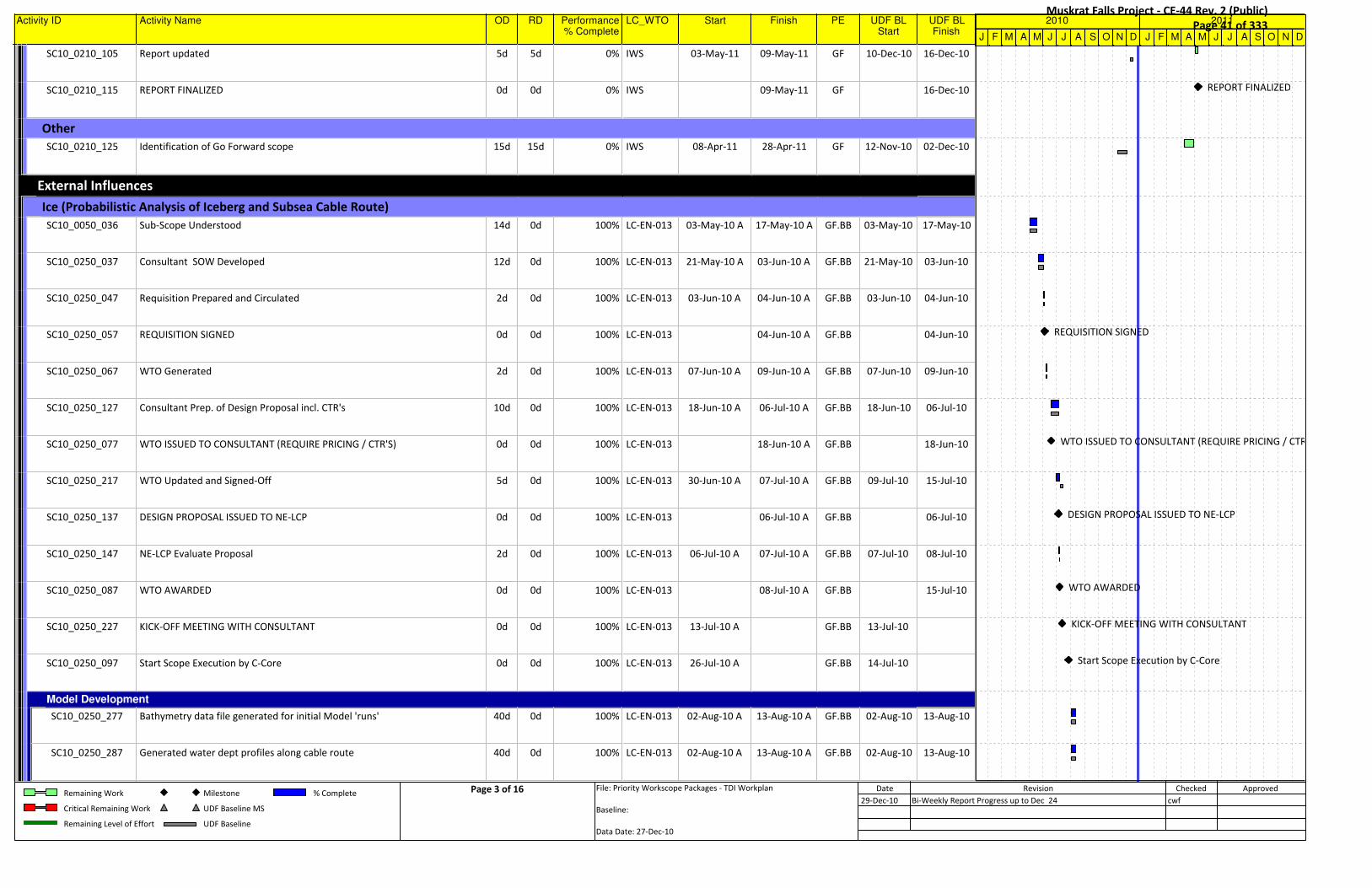
Activity ID Activity Name OD RD Performance% Complete
LC_WTO Start Finish PE UDF BLStart
UDF BLFinish
SC10_0210_105 Report updated 5d 5d 0% IWS 03-May-11 09-May-11 GF 10-Dec-10 16-Dec-10
SC10_0210_115 REPORT FINALIZED 0d 0d 0% IWS 09-May-11 GF 16-Dec-10
OtherOtherOtherOtherOtherOtherOtherOtherOtherOtherOther
SC10_0210_125 Identification of Go Forward scope 15d 15d 0% IWS 08-Apr-11 28-Apr-11 GF 12-Nov-10 02-Dec-10
External InfluencesExternal InfluencesExternal InfluencesExternal InfluencesExternal InfluencesExternal InfluencesExternal InfluencesExternal InfluencesExternal InfluencesExternal InfluencesExternal Influences
Ice (Probabilistic Analysis of Iceberg and Subsea Cable Route)Ice (Probabilistic Analysis of Iceberg and Subsea Cable Route)Ice (Probabilistic Analysis of Iceberg and Subsea Cable Route)Ice (Probabilistic Analysis of Iceberg and Subsea Cable Route)Ice (Probabilistic Analysis of Iceberg and Subsea Cable Route)Ice (Probabilistic Analysis of Iceberg and Subsea Cable Route)Ice (Probabilistic Analysis of Iceberg and Subsea Cable Route)Ice (Probabilistic Analysis of Iceberg and Subsea Cable Route)Ice (Probabilistic Analysis of Iceberg and Subsea Cable Route)Ice (Probabilistic Analysis of Iceberg and Subsea Cable Route)Ice (Probabilistic Analysis of Iceberg and Subsea Cable Route)
SC10_0050_036 Sub-Scope Understood 14d 0d 100% LC-EN-013 03-May-10 A 17-May-10 A GF.BB 03-May-10 17-May-10
SC10_0250_037 Consultant SOW Developed 12d 0d 100% LC-EN-013 21-May-10 A 03-Jun-10 A GF.BB 21-May-10 03-Jun-10
SC10_0250_047 Requisition Prepared and Circulated 2d 0d 100% LC-EN-013 03-Jun-10 A 04-Jun-10 A GF.BB 03-Jun-10 04-Jun-10
SC10_0250_057 REQUISITION SIGNED 0d 0d 100% LC-EN-013 04-Jun-10 A GF.BB 04-Jun-10
SC10_0250_067 WTO Generated 2d 0d 100% LC-EN-013 07-Jun-10 A 09-Jun-10 A GF.BB 07-Jun-10 09-Jun-10
SC10_0250_127 Consultant Prep. of Design Proposal incl. CTR's 10d 0d 100% LC-EN-013 18-Jun-10 A 06-Jul-10 A GF.BB 18-Jun-10 06-Jul-10
SC10_0250_077 WTO ISSUED TO CONSULTANT (REQUIRE PRICING / CTR'S) 0d 0d 100% LC-EN-013 18-Jun-10 A GF.BB 18-Jun-10
SC10_0250_217 WTO Updated and Signed-Off 5d 0d 100% LC-EN-013 30-Jun-10 A 07-Jul-10 A GF.BB 09-Jul-10 15-Jul-10
SC10_0250_137 DESIGN PROPOSAL ISSUED TO NE-LCP 0d 0d 100% LC-EN-013 06-Jul-10 A GF.BB 06-Jul-10
SC10_0250_147 NE-LCP Evaluate Proposal 2d 0d 100% LC-EN-013 06-Jul-10 A 07-Jul-10 A GF.BB 07-Jul-10 08-Jul-10
SC10_0250_087 WTO AWARDED 0d 0d 100% LC-EN-013 08-Jul-10 A GF.BB 15-Jul-10
SC10_0250_227 KICK-OFF MEETING WITH CONSULTANT 0d 0d 100% LC-EN-013 13-Jul-10 A GF.BB 13-Jul-10
SC10_0250_097 Start Scope Execution by C-Core 0d 0d 100% LC-EN-013 26-Jul-10 A GF.BB 14-Jul-10
Model DevelopmentModel DevelopmentModel DevelopmentModel DevelopmentModel DevelopmentModel DevelopmentModel DevelopmentModel DevelopmentModel DevelopmentModel DevelopmentModel Development
SC10_0250_277 Bathymetry data file generated for initial Model 'runs' 40d 0d 100% LC-EN-013 02-Aug-10 A 13-Aug-10 A GF.BB 02-Aug-10 13-Aug-10
SC10_0250_287 Generated water dept profiles along cable route 40d 0d 100% LC-EN-013 02-Aug-10 A 13-Aug-10 A GF.BB 02-Aug-10 13-Aug-10
J F M A M J J A S O N D J F M A M J J A S O N D
2010 2011
REPORT FINALIZED
REQUISITION SIGNED
WTO ISSUED TO CONSULTANT (REQUIRE PRICING / CTR'S)
DESIGN PROPOSAL ISSUED TO NE-LCP
WTO AWARDED
KICK-OFF MEETING WITH CONSULTANT
Start Scope Execution by C-Core
Remaining Work
Critical Remaining Work
Remaining Level of Effort
Milestone
UDF Baseline MS
UDF Baseline
% Complete Page 3 of 16 File: Priority Workscope Packages - TDI Workplan
Baseline:
Data Date: 27-Dec-10
Date Revision Checked Approved
29-Dec-10 Bi-Weekly Report Progress up to Dec 24 cwf
Muskrat Falls Project - CE-44 Rev. 2 (Public) Page 41 of 333

Activity ID Activity Name OD RD Performance% Complete
LC_WTO Start Finish PE UDF BLStart
UDF BLFinish
SC10_0250_297 Draft Report of Model Shell 0d 0d 100% LC-EN-013 13-Aug-10 A GF.BB 31-Aug-10
SC10_0250_307 Acquire/Evaluate alternate bathymetry data to extend model area (CHS) 5d 0d 100% LC-EN-013 16-Aug-10 A 16-Sep-10 A GF.BB 16-Aug-10 20-Aug-10
SC10_0250_317 Analyze available iceberg data for use in model 5d 5d 75% LC-EN-013 16-Aug-10 A 10-Jan-11 GF.BB 17-Aug-10 23-Aug-10
SC10_0250_327 Generate/select relationship for iceberg deterioration 5d 5d 75% LC-EN-013 18-Aug-10 A 17-Jan-11 GF.BB 18-Aug-10 24-Aug-10
SC10_0250_337 Begin coding contact model/generate initial run and evaulate output 5d 5d 75% LC-EN-013 18-Aug-10 A 24-Jan-11 GF.BB 19-Aug-10 25-Aug-10
SC10_0250_347 Document contact model components 5d 5d 75% LC-EN-013 01-Oct-10 A 24-Jan-11 GF.BB 26-Aug-10 01-Sep-10
SC10_0250_377 C-Core Model Finalization 5d 5d 0% LC-EN-013 18-Jan-11 24-Jan-11 GF.BB 26-Aug-10 01-Sep-10
SC10_0250_367 Model Submitted to NE-LCP 2d 2d 0% LC-EN-013 25-Jan-11 26-Jan-11 GF.BB 26-Aug-10 01-Sep-10
Scour AnalysisScour AnalysisScour AnalysisScour AnalysisScour AnalysisScour AnalysisScour AnalysisScour AnalysisScour AnalysisScour AnalysisScour Analysis
SC10_0250_247 (LC-EN-013), Scour Analysis Database Delivery to C-Core (Jacques to Provide
SOBI Bathymetry/Scouring D-Base)
40d 7d 90% LC-EN-013 16-Aug-10 A 12-Jan-11 GF.BB 21-Jul-10 16-Sep-10
Cable Risk AssessmentCable Risk AssessmentCable Risk AssessmentCable Risk AssessmentCable Risk AssessmentCable Risk AssessmentCable Risk AssessmentCable Risk AssessmentCable Risk AssessmentCable Risk AssessmentCable Risk Assessment
SC10_0250_257 C-Core Cable Risk Assessment 40d 2d 75% LC-EN-013 30-Aug-10 A 14-Jan-11 GF.BB 21-Jul-10 16-Sep-10
ReportingReportingReportingReportingReportingReportingReportingReportingReportingReportingReporting
SC10_0250_267 C-Core, Reporting (Incl. project Mgt.) 14d 3d 75% LC-EN-013 11-Oct-10 A 19-Jan-11 GF.BB 21-Jul-10 16-Sep-10
SC10_0250_107 SCOPE COMPLETE - Report Submittal for NE_LCP Review 0d 0d 0% LC-EN-013 19-Jan-11 GF.BB 16-Sep-10
SC10_0250_117 Closed-out 5d 5d 0% LC-EN-013 20-Jan-11 26-Jan-11 GF.BB 17-Sep-10 23-Sep-10
Sea CurrentsSea CurrentsSea CurrentsSea CurrentsSea CurrentsSea CurrentsSea CurrentsSea CurrentsSea CurrentsSea CurrentsSea Currents
SC10_0040_031 Sub-Scope Understood 1d 0d 100% 03-May-10 A 21-May-10 A GF.BB 03-May-10 21-May-10
SC10_0150_032 Consultant SOW Developed 10d 0d 100% 21-May-10 A 03-Jun-10 A GF.BB 21-May-10 03-Jun-10
SC10_0230_033 Requisition Prepared and Circulated 40d 0d 100% 03-Jun-10 A 04-Jun-10 A GF.BB 03-Jun-10 04-Jun-10
SC10_0240_034 Requisition Signed 5d 0d 100% 04-Jun-10 A 07-Jun-10 A GF.BB 04-Jun-10 07-Jun-10
SC10_0240_044 WTO Generated 5d 0d 100% 07-Jun-10 A 09-Jun-10 A GF.BB 07-Jun-10 09-Jun-10
J F M A M J J A S O N D J F M A M J J A S O N D
2010 2011
Draft Report of Model Shell
SCOPE COMPLETE - Report Submittal for NE_LCP Review
Remaining Work
Critical Remaining Work
Remaining Level of Effort
Milestone
UDF Baseline MS
UDF Baseline
% Complete Page 4 of 16 File: Priority Workscope Packages - TDI Workplan
Baseline:
Data Date: 27-Dec-10
Date Revision Checked Approved
29-Dec-10 Bi-Weekly Report Progress up to Dec 24 cwf
Muskrat Falls Project - CE-44 Rev. 2 (Public) Page 42 of 333
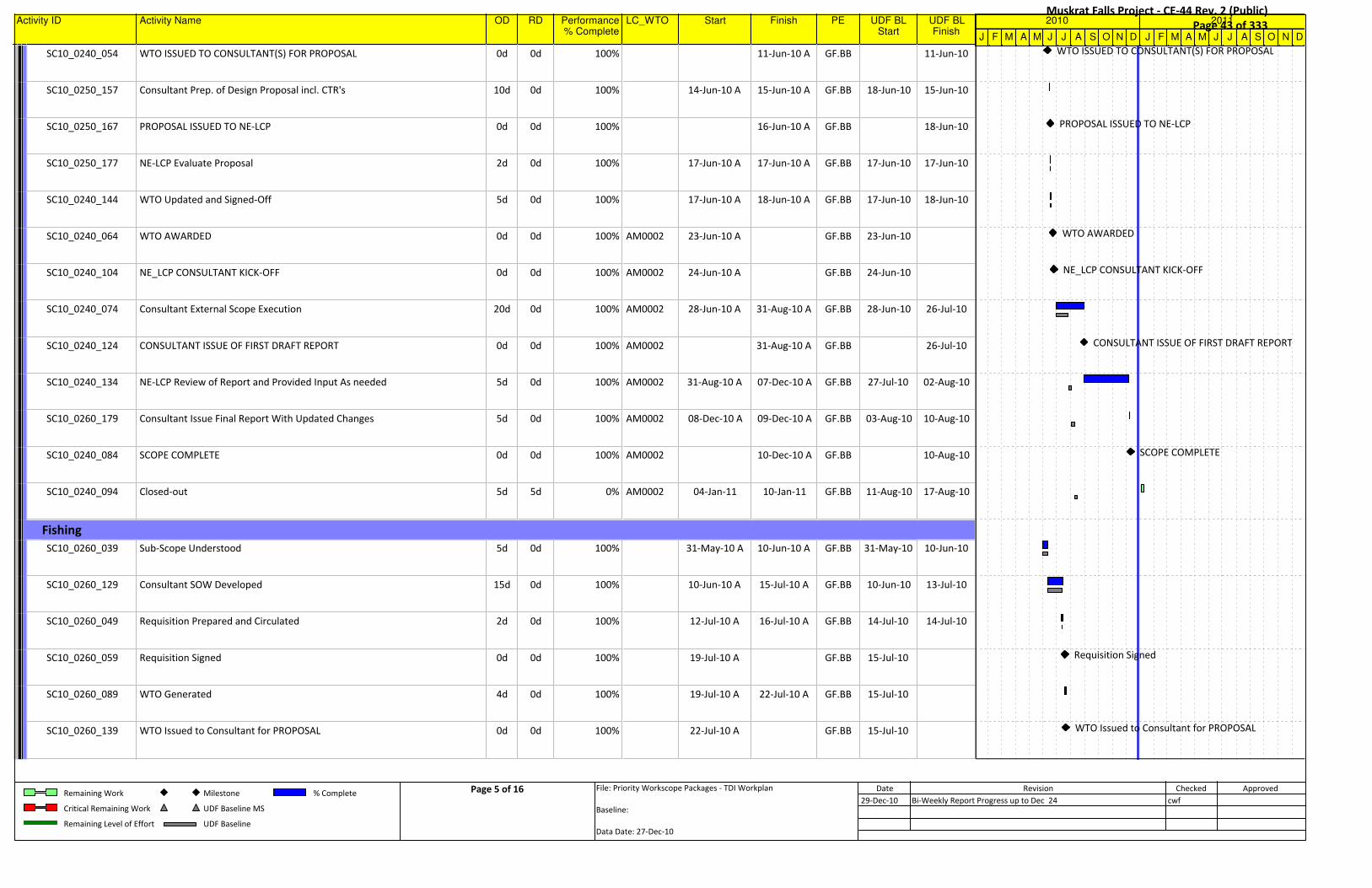
Activity ID Activity Name OD RD Performance% Complete
LC_WTO Start Finish PE UDF BLStart
UDF BLFinish
SC10_0240_054 WTO ISSUED TO CONSULTANT(S) FOR PROPOSAL 0d 0d 100% 11-Jun-10 A GF.BB 11-Jun-10
SC10_0250_157 Consultant Prep. of Design Proposal incl. CTR's 10d 0d 100% 14-Jun-10 A 15-Jun-10 A GF.BB 18-Jun-10 15-Jun-10
SC10_0250_167 PROPOSAL ISSUED TO NE-LCP 0d 0d 100% 16-Jun-10 A GF.BB 18-Jun-10
SC10_0250_177 NE-LCP Evaluate Proposal 2d 0d 100% 17-Jun-10 A 17-Jun-10 A GF.BB 17-Jun-10 17-Jun-10
SC10_0240_144 WTO Updated and Signed-Off 5d 0d 100% 17-Jun-10 A 18-Jun-10 A GF.BB 17-Jun-10 18-Jun-10
SC10_0240_064 WTO AWARDED 0d 0d 100% AM0002 23-Jun-10 A GF.BB 23-Jun-10
SC10_0240_104 NE_LCP CONSULTANT KICK-OFF 0d 0d 100% AM0002 24-Jun-10 A GF.BB 24-Jun-10
SC10_0240_074 Consultant External Scope Execution 20d 0d 100% AM0002 28-Jun-10 A 31-Aug-10 A GF.BB 28-Jun-10 26-Jul-10
SC10_0240_124 CONSULTANT ISSUE OF FIRST DRAFT REPORT 0d 0d 100% AM0002 31-Aug-10 A GF.BB 26-Jul-10
SC10_0240_134 NE-LCP Review of Report and Provided Input As needed 5d 0d 100% AM0002 31-Aug-10 A 07-Dec-10 A GF.BB 27-Jul-10 02-Aug-10
SC10_0260_179 Consultant Issue Final Report With Updated Changes 5d 0d 100% AM0002 08-Dec-10 A 09-Dec-10 A GF.BB 03-Aug-10 10-Aug-10
SC10_0240_084 SCOPE COMPLETE 0d 0d 100% AM0002 10-Dec-10 A GF.BB 10-Aug-10
SC10_0240_094 Closed-out 5d 5d 0% AM0002 04-Jan-11 10-Jan-11 GF.BB 11-Aug-10 17-Aug-10
FishingFishingFishingFishingFishingFishingFishingFishingFishingFishingFishing
SC10_0260_039 Sub-Scope Understood 5d 0d 100% 31-May-10 A 10-Jun-10 A GF.BB 31-May-10 10-Jun-10
SC10_0260_129 Consultant SOW Developed 15d 0d 100% 10-Jun-10 A 15-Jul-10 A GF.BB 10-Jun-10 13-Jul-10
SC10_0260_049 Requisition Prepared and Circulated 2d 0d 100% 12-Jul-10 A 16-Jul-10 A GF.BB 14-Jul-10 14-Jul-10
SC10_0260_059 Requisition Signed 0d 0d 100% 19-Jul-10 A GF.BB 15-Jul-10
SC10_0260_089 WTO Generated 4d 0d 100% 19-Jul-10 A 22-Jul-10 A GF.BB 15-Jul-10
SC10_0260_139 WTO Issued to Consultant for PROPOSAL 0d 0d 100% 22-Jul-10 A GF.BB 15-Jul-10
J F M A M J J A S O N D J F M A M J J A S O N D
2010 2011
WTO ISSUED TO CONSULTANT(S) FOR PROPOSAL
PROPOSAL ISSUED TO NE-LCP
WTO AWARDED
NE_LCP CONSULTANT KICK-OFF
CONSULTANT ISSUE OF FIRST DRAFT REPORT
SCOPE COMPLETE
Requisition Signed
WTO Issued to Consultant for PROPOSAL
Remaining Work
Critical Remaining Work
Remaining Level of Effort
Milestone
UDF Baseline MS
UDF Baseline
% Complete Page 5 of 16 File: Priority Workscope Packages - TDI Workplan
Baseline:
Data Date: 27-Dec-10
Date Revision Checked Approved
29-Dec-10 Bi-Weekly Report Progress up to Dec 24 cwf
Muskrat Falls Project - CE-44 Rev. 2 (Public) Page 43 of 333

Activity ID Activity Name OD RD Performance% Complete
LC_WTO Start Finish PE UDF BLStart
UDF BLFinish
SC10_0250_187 Consultant Prep. of Design Proposal incl. CTR's 10d 0d 100% 23-Jul-10 A 27-Jul-10 A GF.BB 21-Jul-10 03-Aug-10
SC10_0250_207 NE-LCP Evaluate Proposal 2d 0d 100% 23-Jul-10 A 26-Jul-10 A GF.BB 05-Aug-10 06-Aug-10
SC10_0250_197 Consultant Proposal Issued to NE-LCP 0d 0d 100% 27-Jul-10 A GF.BB 03-Aug-10
SC10_0260_079 CONTRACT / WTO ISSUED TO CONSULTANT 0d 0d 100% LC-EN-019 30-Jul-10 A GF.BB 21-Jul-10
SC10_0240_114 NE_LCP Consultant Kick-off 0d 0d 100% LC-EN-019 02-Aug-10 A GF.BB 17-Aug-10
SC10_0260_099 External Scope Execution 15d 0d 100% LC-EN-019 04-Aug-10 A 08-Oct-10 A GF.BB 19-Aug-10 16-Sep-10
SC10_0260_149 CONSULTANT ISSUE DRAFT REPORT 0d 0d 100% LC-EN-019 16-Sep-10 A GF.BB 16-Sep-10
SC10_0260_159 NE-LCP Review of Report and Provide Input As needed 5d 0d 100% LC-EN-019 17-Sep-10 A 05-Nov-10 A GF.BB 17-Sep-10 23-Sep-10
SC10_0260_169 Consultant Issue Final Report With Updated Changes 5d 0d 100% LC-EN-019 12-Nov-10 A 16-Nov-10 A GF.BB 24-Sep-10 30-Sep-10
SC10_0260_109 SCOPE COMPLETE 0d 0d 100% LC-EN-019 26-Nov-10 A GF.BB 30-Sep-10
SC10_0260_119 Closed-out 9d 9d 0% LC-EN-019 04-Jan-11 14-Jan-11 GF.BB 01-Oct-10 07-Oct-10
Vessel Traffic RiskVessel Traffic RiskVessel Traffic RiskVessel Traffic RiskVessel Traffic RiskVessel Traffic RiskVessel Traffic RiskVessel Traffic RiskVessel Traffic RiskVessel Traffic RiskVessel Traffic Risk
SC10_0270_041 Sub-Scope Understood 10d 0d 100% 28-Apr-10 A 12-May-10 A GF 28-Apr-10 12-May-10
SC10_0290_042 Gathering of External Information 4d 0d 100% 13-May-10 A 19-May-10 A GF 13-May-10 19-May-10
SC10_0290_052 Analysis performed 5d 0d 100% 20-May-10 A 14-Sep-10 A GF 20-May-10 19-Aug-10
SC10_0290_062 Scope Complete 0d 0d 100% 15-Sep-10 A GF 24-Jun-10
SC10_0290_072 Closed-out 5d 0d 100% 16-Sep-10 A 17-Sep-10 A GF 25-Jun-10 06-Jul-10
Transmission Definition / CablesTransmission Definition / CablesTransmission Definition / CablesTransmission Definition / CablesTransmission Definition / CablesTransmission Definition / CablesTransmission Definition / CablesTransmission Definition / CablesTransmission Definition / CablesTransmission Definition / CablesTransmission Definition / Cables
Transmission DefinitionTransmission DefinitionTransmission DefinitionTransmission DefinitionTransmission DefinitionTransmission DefinitionTransmission DefinitionTransmission DefinitionTransmission DefinitionTransmission DefinitionTransmission Definition
SC10_0290_082 Identify transmission requirements 15d 0d 100% 24-May-10 A 06-Aug-10 A GF.TR 24-May-10 18-Jun-10
SC10_0290_112 Capture and updated LCP Design Basis Reflect 1d 0d 100% 16-Jun-10 A 27-Aug-10 A GF.TR 16-Jun-10 21-Jun-10
Technology ReviewTechnology ReviewTechnology ReviewTechnology ReviewTechnology ReviewTechnology ReviewTechnology ReviewTechnology ReviewTechnology ReviewTechnology ReviewTechnology Review
J F M A M J J A S O N D J F M A M J J A S O N D
2010 2011
Consultant Proposal Issued to NE-LCP
CONTRACT / WTO ISSUED TO CONSULTANT
NE_LCP Consultant Kick-off
CONSULTANT ISSUE DRAFT REPORT
SCOPE COMPLETE
Scope Complete
Remaining Work
Critical Remaining Work
Remaining Level of Effort
Milestone
UDF Baseline MS
UDF Baseline
% Complete Page 6 of 16 File: Priority Workscope Packages - TDI Workplan
Baseline:
Data Date: 27-Dec-10
Date Revision Checked Approved
29-Dec-10 Bi-Weekly Report Progress up to Dec 24 cwf
Muskrat Falls Project - CE-44 Rev. 2 (Public) Page 44 of 333

Activity ID Activity Name OD RD Performance% Complete
LC_WTO Start Finish PE UDF BLStart
UDF BLFinish
SC10_0290_092 Identify Suppliers and capture information 14d 0d 100% 03-May-10 A 04-Jun-10 A GF.TR 03-May-10 04-Jun-10
SC10_0290_132 Identify relevant world projects and capture information 20d 0d 100% 03-May-10 A 27-Aug-10 A GF.TR 03-May-10 22-Jun-10
Vendor Cable Information / Preliminary DesignVendor Cable Information / Preliminary DesignVendor Cable Information / Preliminary DesignVendor Cable Information / Preliminary DesignVendor Cable Information / Preliminary DesignVendor Cable Information / Preliminary DesignVendor Cable Information / Preliminary DesignVendor Cable Information / Preliminary DesignVendor Cable Information / Preliminary DesignVendor Cable Information / Preliminary DesignVendor Cable Information / Preliminary Design
SC10_0290_102 Prepare a technical query document for cable manufacturers - Develop SOW 8d 0d 100% 09-Jun-10 A 30-Jun-10 A GF.TR 09-Jun-10 25-Jun-10
SC10_0290_152 REQUISITION(S) SIGNED 0d 0d 100% 23-Jun-10 A GF.TR 23-Jun-10
SC10_0290_142 Requisition(s) Prepared and Circulated 3d 0d 100% 24-Jun-10 A 28-Jun-10 A GF.TR 18-Jun-10 22-Jun-10
SC10_0290_162 WTO'S GENERATED 4d 0d 50% 28-Jun-10 A 04-Jan-11 GF.TR 23-Jun-10 29-Jun-10
SC10_0290_172 WTO ISSUED TO CONSULTANT(S) FOR PROPOSAL 0d 0d 0% 04-Jan-11 GF.TR 30-Jun-10
ABBABBABBABBABBABBABBABBABBABBABB
SC10_0290_192 Consultant Development of Proposal With CTR's 10d 0d 100% 07-Jul-10 A 12-Aug-10 A GF.TR 07-Jul-10 12-Jul-10
SC10_0290_372 PROPOSAL ISSUED TO NE-LCP 0d 0d 100% 13-Aug-10 A GF.TR 16-Jul-10
SC10_0290_382 Proposal Evaluated By NE-LCP 2d 0d 100% 17-Aug-10 A 25-Aug-10 A GF.TR 16-Jul-10 16-Jul-10
SC10_0290_632 NE-LCP Meetings with ABB 2d 0d 100% 25-Aug-10 A 31-Aug-10 A GF.TR 16-Jul-10 16-Jul-10
SC10_0290_422 WTO Legal Review process / Contract negotiations with ABB 5d 0d 100% 15-Oct-10 A 26-Nov-10 A GF.TR 20-Jul-10 26-Jul-10
SC10_0290_392 WTO Updated and Signed-Off 5d 6d 95% 22-Oct-10 A 11-Jan-11 GF.TR 20-Jul-10 26-Jul-10
SC10_0290_402 WTO AWARDED 0d 0d 0% 12-Jan-11 GF.TR 27-Jul-10
SC10_0290_412 KICK-OFF MEETING WITH CONSULTANT 0d 0d 0% 13-Jan-11 GF.TR 28-Jul-10
SC10_0290_232 External Scope Execution 20d 48d 0% 17-Jan-11 23-Mar-11 GF.TR 30-Jul-10 27-Aug-10
SC10_0260_219 CONSULTANT ISSUE DRAFT REPORT 0d 0d 0% 23-Mar-11 GF.TR 27-Aug-10
SC10_0260_229 NE-LCP Review of Report and Provide Input As needed 5d 5d 0% 24-Mar-11 30-Mar-11 GF.TR 30-Aug-10 06-Sep-10
SC10_0260_239 Consultant Issue Final Report With Updated Changes 5d 5d 0% 31-Mar-11 07-Apr-11 GF.TR 07-Sep-10 13-Sep-10
J F M A M J J A S O N D J F M A M J J A S O N D
2010 2011
REQUISITION(S) SIGNED
WTO ISSUED TO CONSULTANT(S) FOR PROPOSAL
PROPOSAL ISSUED TO NE-LCP
WTO AWARDED
KICK-OFF MEETING WITH CONSULTANT
CONSULTANT ISSUE DRAFT REPORT
Remaining Work
Critical Remaining Work
Remaining Level of Effort
Milestone
UDF Baseline MS
UDF Baseline
% Complete Page 7 of 16 File: Priority Workscope Packages - TDI Workplan
Baseline:
Data Date: 27-Dec-10
Date Revision Checked Approved
29-Dec-10 Bi-Weekly Report Progress up to Dec 24 cwf
Muskrat Falls Project - CE-44 Rev. 2 (Public) Page 45 of 333

Activity ID Activity Name OD RD Performance% Complete
LC_WTO Start Finish PE UDF BLStart
UDF BLFinish
SC10_0290_242 Scope Complete 0d 0d 0% 07-Apr-11 GF.TR 13-Sep-10
SC10_0290_282 Closed-out 5d 5d 0% 08-Apr-11 14-Apr-11 GF.TR 14-Sep-10 20-Sep-10
NexansNexansNexansNexansNexansNexansNexansNexansNexansNexansNexans
SC10_0290_212 External Scope Execution 20d 0d 100% 24-Aug-10 A 28-Oct-10 A GF.TR 30-Jul-10 27-Aug-10
SC10_0290_342 NE-LCP Meetings with Nexan 2d 0d 100% 24-Aug-10 A 26-Aug-10 A GF.TR 24-Aug-10 25-Aug-10
SC10_0260_189 CONSULTANT ISSUE DRAFT REPORT 2d 0d 100% 01-Sep-10 A 30-Oct-10 A GF.TR 27-Aug-10
SC10_0260_199 NE-LCP Review of Report and Provide Input As needed 5d 0d 100% 10-Nov-10 A 10-Dec-10 A GF.TR 30-Aug-10 06-Sep-10
SC10_0260_209 Consultant Issue Final Report With Updated Changes 10d 0d 100% 08-Dec-10 A 10-Dec-10 A GF.TR 07-Sep-10 13-Sep-10
SC10_0290_222 Scope Complete 0d 0d 100% 10-Dec-10 A GF.TR 13-Sep-10
SC10_0290_292 Closed-out 5d 5d 0% 07-Jan-11 13-Jan-11 GF.TR 14-Sep-10 20-Sep-10
PrysmianPrysmianPrysmianPrysmianPrysmianPrysmianPrysmianPrysmianPrysmianPrysmianPrysmian
SC10_0290_252 External Scope Execution (Not under NE-LCP Contract) 20d 0d 100% 02-Aug-10 A 31-Aug-10 A GF.TR 30-Jul-10 27-Aug-10
SC10_0260_249 CONSULTANT ISSUE DRAFT REPORT 0d 0d 100% 31-Aug-10 A GF.TR 27-Aug-10
SC10_0260_259 NE-LCP Review of Report and Provide Input As needed 5d 0d 100% 31-Aug-10 A 03-Sep-10 A GF.TR 30-Aug-10 06-Sep-10
SC10_0290_352 SOBI Team Meeting with Prysmian 0d 0d 100% 18-Oct-10 A 19-Oct-10 A GF.TR 13-Sep-10
SC10_0290_262 Scope Complete 0d 0d 100% 09-Nov-10 A GF.TR 13-Sep-10
SC10_0290_272 Closed-out 5d 0d 100% 01-Dec-10 A 08-Dec-10 A GF.TR 14-Sep-10 20-Sep-10
Study OutcomeStudy OutcomeStudy OutcomeStudy OutcomeStudy OutcomeStudy OutcomeStudy OutcomeStudy OutcomeStudy OutcomeStudy OutcomeStudy Outcome
SC10_0290_312 Cable Recommendation Summary 25d 72d 50% 03-May-10 A 14-Apr-11 GF.TR 03-May-10 20-Sep-10
SC10_0290_302 Review of External works and analysis 5d 5d 0% 08-Apr-11 14-Apr-11 GF.TR 14-Sep-10 20-Sep-10
Conceptual Design RoutingConceptual Design RoutingConceptual Design RoutingConceptual Design RoutingConceptual Design RoutingConceptual Design RoutingConceptual Design RoutingConceptual Design RoutingConceptual Design RoutingConceptual Design RoutingConceptual Design Routing
SC10_0060_079 Determine Zone Boundaries 5d 0d 98% 05-Jul-10 A 20-Jan-11 GF 01-Oct-10 07-Oct-10
J F M A M J J A S O N D J F M A M J J A S O N D
2010 2011
Scope Complete
Scope Complete
CONSULTANT ISSUE DRAFT REPORT
Scope Complete
Remaining Work
Critical Remaining Work
Remaining Level of Effort
Milestone
UDF Baseline MS
UDF Baseline
% Complete Page 8 of 16 File: Priority Workscope Packages - TDI Workplan
Baseline:
Data Date: 27-Dec-10
Date Revision Checked Approved
29-Dec-10 Bi-Weekly Report Progress up to Dec 24 cwf
Muskrat Falls Project - CE-44 Rev. 2 (Public) Page 46 of 333

Activity ID Activity Name OD RD Performance% Complete
LC_WTO Start Finish PE UDF BLStart
UDF BLFinish
SC10_0060_099 Route selection in each Zone as based on other sub-scopes 10d 10d 95% 05-Jul-10 A 02-Feb-11 GF 11-Oct-10 22-Oct-10
SC10_0060_089 Zones Finalized 0d 0d 0% 20-Jan-11 GF 07-Oct-10
SC10_0060_109 Route finalized 0d 0d 0% 02-Feb-11 GF 22-Oct-10
ProtectionProtectionProtectionProtectionProtectionProtectionProtectionProtectionProtectionProtectionProtection
Rock Placement (Berm)Rock Placement (Berm)Rock Placement (Berm)Rock Placement (Berm)Rock Placement (Berm)Rock Placement (Berm)Rock Placement (Berm)Rock Placement (Berm)Rock Placement (Berm)Rock Placement (Berm)Rock Placement (Berm)
SC10_0410_058 Investgation of Global Rock Placement contractors 25d 0d 100% LC-EN-018 03-May-10 A 31-May-10 A GF.BB 03-May-10 31-May-10
SC10_0420_059 Select Contractors to engage 5d 0d 100% LC-EN-018 31-May-10 A 06-Aug-10 A GF.BB 31-May-10 22-Jun-10
SC10_0410_068 Prepare SOW Developed and Issued For External Scope 10d 0d 100% LC-EN-018 01-Jun-10 A 04-Aug-10 A GF.BB 22-Jun-10 09-Jul-10
SC10_0410_078 Requisition Prepared 2d 0d 100% LC-EN-018 03-Aug-10 A 05-Aug-10 A GF.BB 09-Jul-10 12-Jul-10
SC10_0290_322 WTO'S GENERATED 4d 0d 100% LC-EN-018 24-Aug-10 A 27-Aug-10 A GF.BB 23-Jun-10 29-Jun-10
SC10_0410_108 Requisition Signed 0d 0d 100% LC-EN-018 27-Aug-10 A GF.BB 12-Jul-10
SC10_0290_332 WTO ISSUED TO CONSULTANT(S) FOR PROPOSAL 0d 0d 100% LC-EN-018 27-Aug-10 A GF.BB 30-Jun-10
SC10_0290_362 SOBI Team Meeting with Rock Berm Consultant 0d 0d 100% 18-Oct-10 A 19-Oct-10 A GF.TR 13-Sep-10
VAN OORD (SCOPE WILL NOT BE EXECUTED)VAN OORD (SCOPE WILL NOT BE EXECUTED)VAN OORD (SCOPE WILL NOT BE EXECUTED)VAN OORD (SCOPE WILL NOT BE EXECUTED)VAN OORD (SCOPE WILL NOT BE EXECUTED)VAN OORD (SCOPE WILL NOT BE EXECUTED)VAN OORD (SCOPE WILL NOT BE EXECUTED)VAN OORD (SCOPE WILL NOT BE EXECUTED)VAN OORD (SCOPE WILL NOT BE EXECUTED)VAN OORD (SCOPE WILL NOT BE EXECUTED)VAN OORD (SCOPE WILL NOT BE EXECUTED)
TidewayTidewayTidewayTidewayTidewayTidewayTidewayTidewayTidewayTidewayTideway
SC10_0290_472 Consultant Development of Proposal With CTR's 10d 0d 100% LC-EN-018 04-Aug-10 A 18-Aug-10 A GF.BB 16-Jul-10 30-Jul-10
SC10_0290_482 PROPOSAL ISSUED TO NE-LCP 0d 0d 100% LC-EN-018 18-Aug-10 A GF.BB 30-Jul-10
SC10_0290_492 Proposal Evaluated By NE-LCP 2d 0d 100% LC-EN-018 18-Aug-10 A 30-Aug-10 A GF.BB 30-Jul-10 03-Aug-10
SC10_0290_502 WTO Updated and Signed-Off 5d 0d 100% LC-EN-018 31-Aug-10 A 01-Sep-10 A GF.BB 03-Aug-10 11-Aug-10
SC10_0410_138 External Scope Execution 20d 0d 100% LC-EN-018 01-Sep-10 A 10-Dec-10 A GF.BB 16-Aug-10 14-Sep-10
SC10_0290_512 WTO AWARDED 0d 0d 100% LC-EN-018 01-Sep-10 A GF.BB 11-Aug-10
SC10_0290_522 KICK-OFF MEETING WITH CONSULTANT 0d 0d 100% LC-EN-018 01-Sep-10 A GF.BB 12-Aug-10
J F M A M J J A S O N D J F M A M J J A S O N D
2010 2011
Zones Finalized
Route finalized
Requisition Signed
WTO ISSUED TO CONSULTANT(S) FOR PROPOSAL
PROPOSAL ISSUED TO NE-LCP
WTO AWARDED
KICK-OFF MEETING WITH CONSULTANT
Remaining Work
Critical Remaining Work
Remaining Level of Effort
Milestone
UDF Baseline MS
UDF Baseline
% Complete Page 9 of 16 File: Priority Workscope Packages - TDI Workplan
Baseline:
Data Date: 27-Dec-10
Date Revision Checked Approved
29-Dec-10 Bi-Weekly Report Progress up to Dec 24 cwf
Muskrat Falls Project - CE-44 Rev. 2 (Public) Page 47 of 333
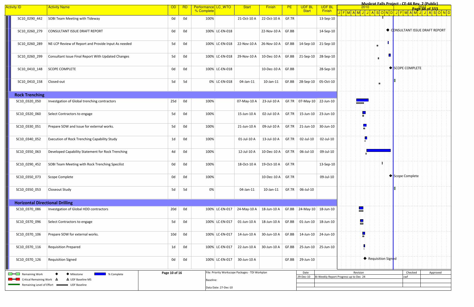
Activity ID Activity Name OD RD Performance% Complete
LC_WTO Start Finish PE UDF BLStart
UDF BLFinish
SC10_0290_442 SOBI Team Meeting with Tideway 0d 0d 100% 21-Oct-10 A 22-Oct-10 A GF.TR 13-Sep-10
SC10_0260_279 CONSULTANT ISSUE DRAFT REPORT 0d 0d 100% LC-EN-018 22-Nov-10 A GF.BB 14-Sep-10
SC10_0260_289 NE-LCP Review of Report and Provide Input As needed 5d 0d 100% LC-EN-018 22-Nov-10 A 26-Nov-10 A GF.BB 14-Sep-10 21-Sep-10
SC10_0260_299 Consultant Issue Final Report With Updated Changes 5d 0d 100% LC-EN-018 29-Nov-10 A 10-Dec-10 A GF.BB 21-Sep-10 28-Sep-10
SC10_0410_148 SCOPE COMPLETE 0d 0d 100% LC-EN-018 10-Dec-10 A GF.BB 28-Sep-10
SC10_0410_158 Closed-out 5d 5d 0% LC-EN-018 04-Jan-11 10-Jan-11 GF.BB 28-Sep-10 05-Oct-10
Rock TrenchingRock TrenchingRock TrenchingRock TrenchingRock TrenchingRock TrenchingRock TrenchingRock TrenchingRock TrenchingRock TrenchingRock Trenching
SC10_0320_050 Investgation of Global trenching contractors 25d 0d 100% 07-May-10 A 23-Jul-10 A GF.TR 07-May-10 22-Jun-10
SC10_0320_060 Select Contractors to engage 5d 0d 100% 15-Jun-10 A 02-Jul-10 A GF.TR 15-Jun-10 23-Jun-10
SC10_0330_051 Prepare SOW and Issue for external works. 5d 0d 100% 21-Jun-10 A 09-Jul-10 A GF.TR 21-Jun-10 30-Jun-10
SC10_0340_052 Execution of Rock Trenching Capability Study 1d 0d 100% 01-Jul-10 A 13-Jul-10 A GF.TR 02-Jul-10 02-Jul-10
SC10_0350_063 Developed Capability Statement for Rock Trenching 4d 0d 100% 12-Jul-10 A 10-Dec-10 A GF.TR 06-Jul-10 09-Jul-10
SC10_0290_452 SOBI Team Meeting with Rock Trenching Specilist 0d 0d 100% 18-Oct-10 A 19-Oct-10 A GF.TR 13-Sep-10
SC10_0350_073 Scope Complete 0d 0d 100% 10-Dec-10 A GF.TR 09-Jul-10
SC10_0350_053 Closeout Study 5d 5d 0% 04-Jan-11 10-Jan-11 GF.TR 06-Jul-10
Horizontal Directional DrillingHorizontal Directional DrillingHorizontal Directional DrillingHorizontal Directional DrillingHorizontal Directional DrillingHorizontal Directional DrillingHorizontal Directional DrillingHorizontal Directional DrillingHorizontal Directional DrillingHorizontal Directional DrillingHorizontal Directional Drilling
SC10_0370_086 Investgation of Global HDD contractors 20d 0d 100% LC-EN-017 24-May-10 A 18-Jun-10 A GF.BB 24-May-10 18-Jun-10
SC10_0370_096 Select Contractors to engage 5d 0d 100% LC-EN-017 01-Jun-10 A 18-Jun-10 A GF.BB 01-Jun-10 18-Jun-10
SC10_0370_106 Prepare SOW for external works. 10d 0d 100% LC-EN-017 14-Jun-10 A 30-Jun-10 A GF.BB 14-Jun-10 24-Jun-10
SC10_0370_116 Requisition Prepared 1d 0d 100% LC-EN-017 22-Jun-10 A 30-Jun-10 A GF.BB 25-Jun-10 25-Jun-10
SC10_0370_126 Requisition Signed 0d 0d 100% LC-EN-017 30-Jun-10 A GF.BB 29-Jun-10
J F M A M J J A S O N D J F M A M J J A S O N D
2010 2011
CONSULTANT ISSUE DRAFT REPORT
SCOPE COMPLETE
Scope Complete
Requisition Signed
Remaining Work
Critical Remaining Work
Remaining Level of Effort
Milestone
UDF Baseline MS
UDF Baseline
% Complete Page 10 of 16 File: Priority Workscope Packages - TDI Workplan
Baseline:
Data Date: 27-Dec-10
Date Revision Checked Approved
29-Dec-10 Bi-Weekly Report Progress up to Dec 24 cwf
Muskrat Falls Project - CE-44 Rev. 2 (Public) Page 48 of 333

Activity ID Activity Name OD RD Performance% Complete
LC_WTO Start Finish PE UDF BLStart
UDF BLFinish
SC10_0370_136 WTOs Generated 4d 0d 100% LC-EN-017 30-Jun-10 A 05-Jul-10 A GF.BB 29-Jun-10 06-Jul-10
SC10_0370_146 WTO ISSUED TO CONSULTANT(S) FOR PROPOSAL 0d 0d 100% LC-EN-017 05-Jul-10 A GF.BB 07-Jul-10
Hatch Mott (ENG. Deliverables)Hatch Mott (ENG. Deliverables)Hatch Mott (ENG. Deliverables)Hatch Mott (ENG. Deliverables)Hatch Mott (ENG. Deliverables)Hatch Mott (ENG. Deliverables)Hatch Mott (ENG. Deliverables)Hatch Mott (ENG. Deliverables)Hatch Mott (ENG. Deliverables)Hatch Mott (ENG. Deliverables)Hatch Mott (ENG. Deliverables)
Scope PreparationScope PreparationScope PreparationScope PreparationScope PreparationScope PreparationScope PreparationScope PreparationScope PreparationScope PreparationScope Preparation
SC10_0390_113 Consultant Development of Proposal With CTR's 10d 0d 100% LC-EN-017 05-Jul-10 A 23-Jul-10 A GF.BB 07-Jul-10 20-Jul-10
SC10_0290_752 WTO Updated and Signed-Off 5d 0d 100% LC-EN-017 23-Jul-10 A 29-Jul-10 A GF.BB 23-Jul-10 29-Jul-10
SC10_0290_732 PROPOSAL ISSUED TO NE-LCP 0d 0d 100% LC-EN-017 26-Jul-10 A GF.BB 21-Jul-10
SC10_0290_742 Proposal Evaluated By NE-LCP 2d 0d 100% LC-EN-017 27-Jul-10 A 30-Jul-10 A GF.BB 21-Jul-10 22-Jul-10
SC10_0440_114 WTO Awarded 0d 0d 100% LC-EN-017 30-Jul-10 A GF.BB 30-Jul-10
SC10_0290_762 KICK-OFF MEETING WITH CONSULTANT 0d 0d 100% LC-EN-017 05-Aug-10 A GF.BB 02-Aug-10
SC10_0290_892 NE-LCP Meeting at Hatch-Mott MacDonald Office 2d 0d 100% LC-EN-017 17-Aug-10 A 19-Aug-10 A GF.BB 02-Aug-10
SC10_0290_902 SOBI Site Meeting (NE-LCP / Hatch-Mott) 3d 0d 100% LC-EN-017 03-Sep-10 A 06-Sep-10 A GF.BB 02-Aug-10
Part 1 (Data Review and Feas. DesignPart 1 (Data Review and Feas. DesignPart 1 (Data Review and Feas. DesignPart 1 (Data Review and Feas. DesignPart 1 (Data Review and Feas. DesignPart 1 (Data Review and Feas. DesignPart 1 (Data Review and Feas. DesignPart 1 (Data Review and Feas. DesignPart 1 (Data Review and Feas. DesignPart 1 (Data Review and Feas. DesignPart 1 (Data Review and Feas. Design
SC10_0370_206 Review Exisitng Geotechnical info review 10d 0d 100% LC-EN-017 10-Aug-10 A 08-Oct-10 A GF.BB 09-Aug-10 20-Aug-10
SC10_0370_266 HDD Bore Profiles Development and Conceptual Design 20d 0d 100% LC-EN-017 30-Aug-10 A 04-Oct-10 A GF.BB 13-Sep-10 08-Oct-10
SC10_0370_216 HDD Industry assessment 10d 0d 100% LC-EN-017 31-Aug-10 A 05-Oct-10 A GF.BB 23-Aug-10 03-Sep-10
SC10_0370_286 HDD Assessment of Shoreline Design and Construction challenges 15d 0d 100% LC-EN-017 31-Aug-10 A 05-Oct-10 A GF.BB 23-Aug-10 10-Sep-10
SC10_0370_226 Site Visit 5d 0d 100% LC-EN-017 01-Sep-10 A 03-Sep-10 A GF.BB 06-Sep-10 10-Sep-10
SC10_0370_276 Complete Drawings for HDD Bore Profiles 20d 0d 100% LC-EN-017 28-Sep-10 A 26-Nov-10 A GF.BB 13-Sep-10 08-Oct-10
Part 2 (Cost Estimate / Schedule)Part 2 (Cost Estimate / Schedule)Part 2 (Cost Estimate / Schedule)Part 2 (Cost Estimate / Schedule)Part 2 (Cost Estimate / Schedule)Part 2 (Cost Estimate / Schedule)Part 2 (Cost Estimate / Schedule)Part 2 (Cost Estimate / Schedule)Part 2 (Cost Estimate / Schedule)Part 2 (Cost Estimate / Schedule)Part 2 (Cost Estimate / Schedule)
SC10_0370_416 Develop Risk Mitigation Measure 15d 0d 100% LC-EN-017 31-Aug-10 A 05-Oct-10 A GF.BB 31-Aug-10 22-Sep-10
SC10_0370_376 Develop Construction Schedule (Level 2) 15d 0d 98% LC-EN-017 07-Sep-10 A 04-Jan-11 GF.BB 07-Sep-10 20-Oct-10
SC10_0370_446 Develop Cost Estimate (AACEI Class 3) 15d 0d 100% LC-EN-017 07-Sep-10 A 26-Oct-10 A GF.BB 07-Sep-10 18-Oct-10
J F M A M J J A S O N D J F M A M J J A S O N D
2010 2011
WTO ISSUED TO CONSULTANT(S) FOR PROPOSAL
PROPOSAL ISSUED TO NE-LCP
WTO Awarded
KICK-OFF MEETING WITH CONSULTANT
Remaining Work
Critical Remaining Work
Remaining Level of Effort
Milestone
UDF Baseline MS
UDF Baseline
% Complete Page 11 of 16 File: Priority Workscope Packages - TDI Workplan
Baseline:
Data Date: 27-Dec-10
Date Revision Checked Approved
29-Dec-10 Bi-Weekly Report Progress up to Dec 24 cwf
Muskrat Falls Project - CE-44 Rev. 2 (Public) Page 49 of 333
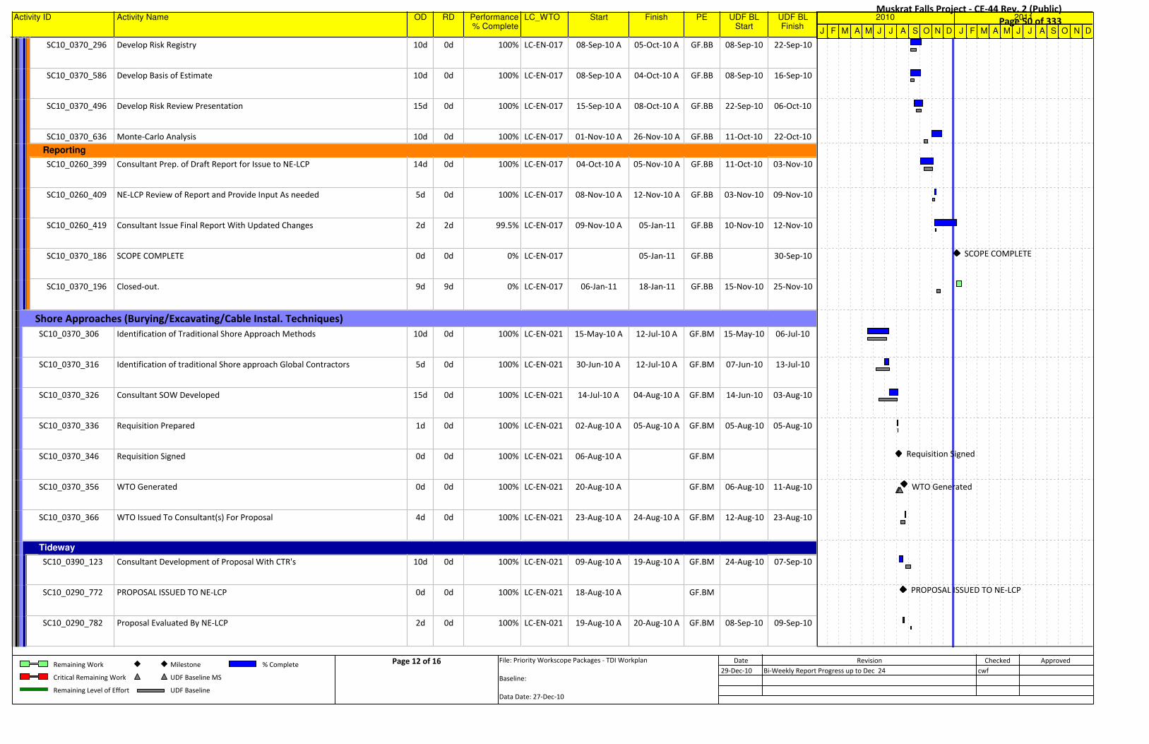
Activity ID Activity Name OD RD Performance% Complete
LC_WTO Start Finish PE UDF BLStart
UDF BLFinish
SC10_0370_296 Develop Risk Registry 10d 0d 100% LC-EN-017 08-Sep-10 A 05-Oct-10 A GF.BB 08-Sep-10 22-Sep-10
SC10_0370_586 Develop Basis of Estimate 10d 0d 100% LC-EN-017 08-Sep-10 A 04-Oct-10 A GF.BB 08-Sep-10 16-Sep-10
SC10_0370_496 Develop Risk Review Presentation 15d 0d 100% LC-EN-017 15-Sep-10 A 08-Oct-10 A GF.BB 22-Sep-10 06-Oct-10
SC10_0370_636 Monte-Carlo Analysis 10d 0d 100% LC-EN-017 01-Nov-10 A 26-Nov-10 A GF.BB 11-Oct-10 22-Oct-10
ReportingReportingReportingReportingReportingReportingReportingReportingReportingReportingReporting
SC10_0260_399 Consultant Prep. of Draft Report for Issue to NE-LCP 14d 0d 100% LC-EN-017 04-Oct-10 A 05-Nov-10 A GF.BB 11-Oct-10 03-Nov-10
SC10_0260_409 NE-LCP Review of Report and Provide Input As needed 5d 0d 100% LC-EN-017 08-Nov-10 A 12-Nov-10 A GF.BB 03-Nov-10 09-Nov-10
SC10_0260_419 Consultant Issue Final Report With Updated Changes 2d 2d 99.5% LC-EN-017 09-Nov-10 A 05-Jan-11 GF.BB 10-Nov-10 12-Nov-10
SC10_0370_186 SCOPE COMPLETE 0d 0d 0% LC-EN-017 05-Jan-11 GF.BB 30-Sep-10
SC10_0370_196 Closed-out. 9d 9d 0% LC-EN-017 06-Jan-11 18-Jan-11 GF.BB 15-Nov-10 25-Nov-10
Shore Approaches (Burying/Excavating/Cable Instal. Techniques)Shore Approaches (Burying/Excavating/Cable Instal. Techniques)Shore Approaches (Burying/Excavating/Cable Instal. Techniques)Shore Approaches (Burying/Excavating/Cable Instal. Techniques)Shore Approaches (Burying/Excavating/Cable Instal. Techniques)Shore Approaches (Burying/Excavating/Cable Instal. Techniques)Shore Approaches (Burying/Excavating/Cable Instal. Techniques)Shore Approaches (Burying/Excavating/Cable Instal. Techniques)Shore Approaches (Burying/Excavating/Cable Instal. Techniques)Shore Approaches (Burying/Excavating/Cable Instal. Techniques)Shore Approaches (Burying/Excavating/Cable Instal. Techniques)
SC10_0370_306 Identification of Traditional Shore Approach Methods 10d 0d 100% LC-EN-021 15-May-10 A 12-Jul-10 A GF.BM 15-May-10 06-Jul-10
SC10_0370_316 Identification of traditional Shore approach Global Contractors 5d 0d 100% LC-EN-021 30-Jun-10 A 12-Jul-10 A GF.BM 07-Jun-10 13-Jul-10
SC10_0370_326 Consultant SOW Developed 15d 0d 100% LC-EN-021 14-Jul-10 A 04-Aug-10 A GF.BM 14-Jun-10 03-Aug-10
SC10_0370_336 Requisition Prepared 1d 0d 100% LC-EN-021 02-Aug-10 A 05-Aug-10 A GF.BM 05-Aug-10 05-Aug-10
SC10_0370_346 Requisition Signed 0d 0d 100% LC-EN-021 06-Aug-10 A GF.BM
SC10_0370_356 WTO Generated 0d 0d 100% LC-EN-021 20-Aug-10 A GF.BM 06-Aug-10 11-Aug-10
SC10_0370_366 WTO Issued To Consultant(s) For Proposal 4d 0d 100% LC-EN-021 23-Aug-10 A 24-Aug-10 A GF.BM 12-Aug-10 23-Aug-10
TidewayTidewayTidewayTidewayTidewayTidewayTidewayTidewayTidewayTidewayTideway
SC10_0390_123 Consultant Development of Proposal With CTR's 10d 0d 100% LC-EN-021 09-Aug-10 A 19-Aug-10 A GF.BM 24-Aug-10 07-Sep-10
SC10_0290_772 PROPOSAL ISSUED TO NE-LCP 0d 0d 100% LC-EN-021 18-Aug-10 A GF.BM
SC10_0290_782 Proposal Evaluated By NE-LCP 2d 0d 100% LC-EN-021 19-Aug-10 A 20-Aug-10 A GF.BM 08-Sep-10 09-Sep-10
J F M A M J J A S O N D J F M A M J J A S O N D
2010 2011
SCOPE COMPLETE
Requisition Signed
WTO Generated
PROPOSAL ISSUED TO NE-LCP
Remaining Work
Critical Remaining Work
Remaining Level of Effort
Milestone
UDF Baseline MS
UDF Baseline
% Complete Page 12 of 16 File: Priority Workscope Packages - TDI Workplan
Baseline:
Data Date: 27-Dec-10
Date Revision Checked Approved
29-Dec-10 Bi-Weekly Report Progress up to Dec 24 cwf
Muskrat Falls Project - CE-44 Rev. 2 (Public) Page 50 of 333
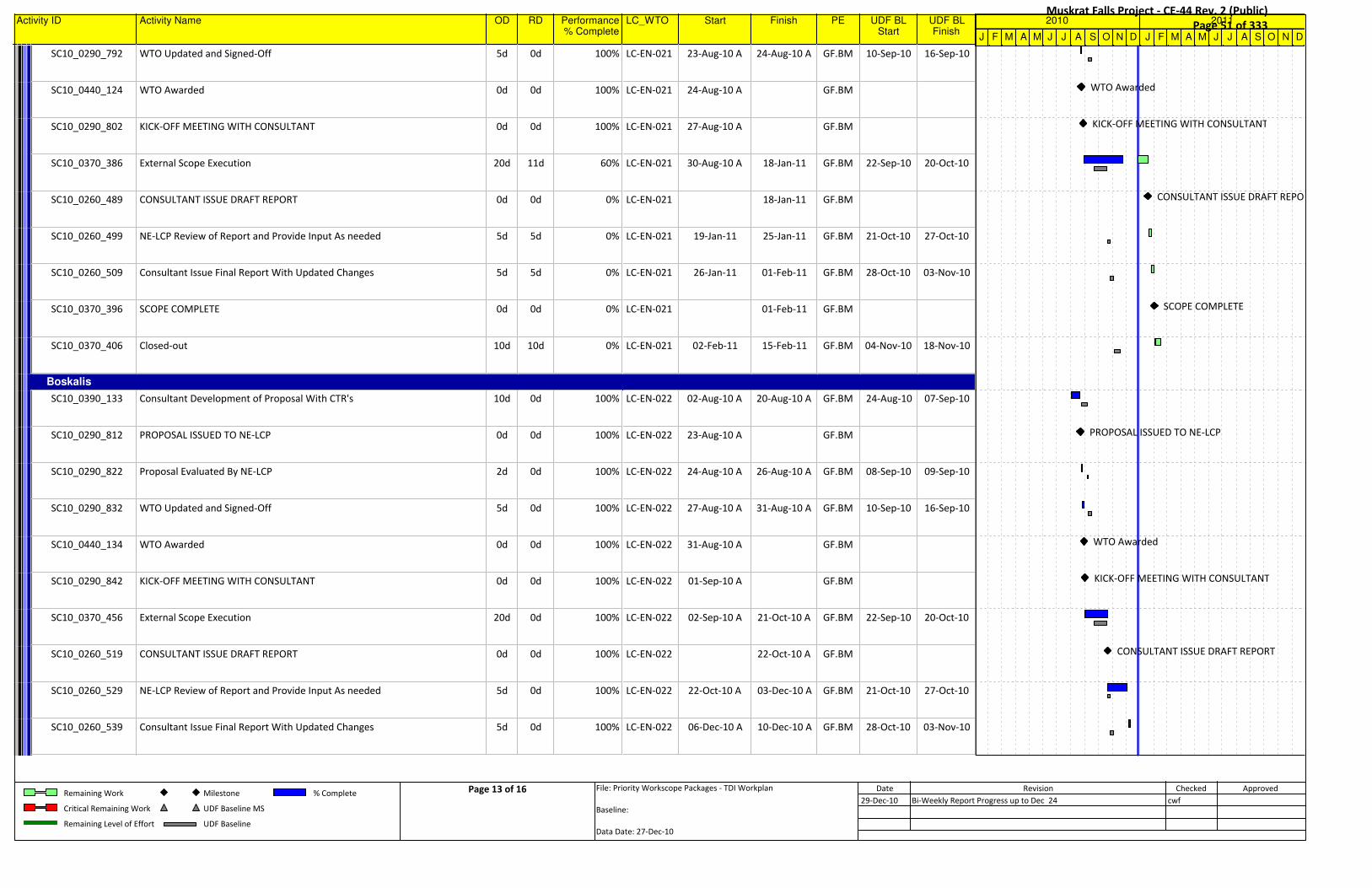
Activity ID Activity Name OD RD Performance% Complete
LC_WTO Start Finish PE UDF BLStart
UDF BLFinish
SC10_0290_792 WTO Updated and Signed-Off 5d 0d 100% LC-EN-021 23-Aug-10 A 24-Aug-10 A GF.BM 10-Sep-10 16-Sep-10
SC10_0440_124 WTO Awarded 0d 0d 100% LC-EN-021 24-Aug-10 A GF.BM
SC10_0290_802 KICK-OFF MEETING WITH CONSULTANT 0d 0d 100% LC-EN-021 27-Aug-10 A GF.BM
SC10_0370_386 External Scope Execution 20d 11d 60% LC-EN-021 30-Aug-10 A 18-Jan-11 GF.BM 22-Sep-10 20-Oct-10
SC10_0260_489 CONSULTANT ISSUE DRAFT REPORT 0d 0d 0% LC-EN-021 18-Jan-11 GF.BM
SC10_0260_499 NE-LCP Review of Report and Provide Input As needed 5d 5d 0% LC-EN-021 19-Jan-11 25-Jan-11 GF.BM 21-Oct-10 27-Oct-10
SC10_0260_509 Consultant Issue Final Report With Updated Changes 5d 5d 0% LC-EN-021 26-Jan-11 01-Feb-11 GF.BM 28-Oct-10 03-Nov-10
SC10_0370_396 SCOPE COMPLETE 0d 0d 0% LC-EN-021 01-Feb-11 GF.BM
SC10_0370_406 Closed-out 10d 10d 0% LC-EN-021 02-Feb-11 15-Feb-11 GF.BM 04-Nov-10 18-Nov-10
BoskalisBoskalisBoskalisBoskalisBoskalisBoskalisBoskalisBoskalisBoskalisBoskalisBoskalis
SC10_0390_133 Consultant Development of Proposal With CTR's 10d 0d 100% LC-EN-022 02-Aug-10 A 20-Aug-10 A GF.BM 24-Aug-10 07-Sep-10
SC10_0290_812 PROPOSAL ISSUED TO NE-LCP 0d 0d 100% LC-EN-022 23-Aug-10 A GF.BM
SC10_0290_822 Proposal Evaluated By NE-LCP 2d 0d 100% LC-EN-022 24-Aug-10 A 26-Aug-10 A GF.BM 08-Sep-10 09-Sep-10
SC10_0290_832 WTO Updated and Signed-Off 5d 0d 100% LC-EN-022 27-Aug-10 A 31-Aug-10 A GF.BM 10-Sep-10 16-Sep-10
SC10_0440_134 WTO Awarded 0d 0d 100% LC-EN-022 31-Aug-10 A GF.BM
SC10_0290_842 KICK-OFF MEETING WITH CONSULTANT 0d 0d 100% LC-EN-022 01-Sep-10 A GF.BM
SC10_0370_456 External Scope Execution 20d 0d 100% LC-EN-022 02-Sep-10 A 21-Oct-10 A GF.BM 22-Sep-10 20-Oct-10
SC10_0260_519 CONSULTANT ISSUE DRAFT REPORT 0d 0d 100% LC-EN-022 22-Oct-10 A GF.BM
SC10_0260_529 NE-LCP Review of Report and Provide Input As needed 5d 0d 100% LC-EN-022 22-Oct-10 A 03-Dec-10 A GF.BM 21-Oct-10 27-Oct-10
SC10_0260_539 Consultant Issue Final Report With Updated Changes 5d 0d 100% LC-EN-022 06-Dec-10 A 10-Dec-10 A GF.BM 28-Oct-10 03-Nov-10
J F M A M J J A S O N D J F M A M J J A S O N D
2010 2011
WTO Awarded
KICK-OFF MEETING WITH CONSULTANT
CONSULTANT ISSUE DRAFT REPORT
SCOPE COMPLETE
PROPOSAL ISSUED TO NE-LCP
WTO Awarded
KICK-OFF MEETING WITH CONSULTANT
CONSULTANT ISSUE DRAFT REPORT
Remaining Work
Critical Remaining Work
Remaining Level of Effort
Milestone
UDF Baseline MS
UDF Baseline
% Complete Page 13 of 16 File: Priority Workscope Packages - TDI Workplan
Baseline:
Data Date: 27-Dec-10
Date Revision Checked Approved
29-Dec-10 Bi-Weekly Report Progress up to Dec 24 cwf
Muskrat Falls Project - CE-44 Rev. 2 (Public) Page 51 of 333
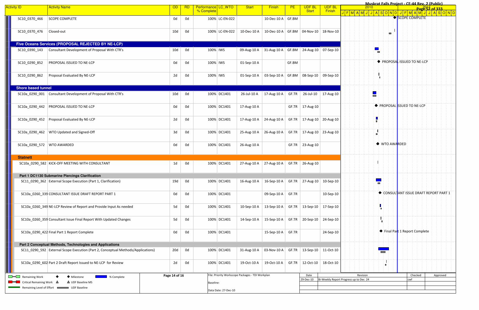
Activity ID Activity Name OD RD Performance% Complete
LC_WTO Start Finish PE UDF BLStart
UDF BLFinish
SC10_0370_466 SCOPE COMPLETE 0d 0d 100% LC-EN-022 10-Dec-10 A GF.BM
SC10_0370_476 Closed-out 10d 0d 100% LC-EN-022 10-Dec-10 A 10-Dec-10 A GF.BM 04-Nov-10 18-Nov-10
Five Oceans Services (PROPOSAL REJECTED BY NE-LCP)Five Oceans Services (PROPOSAL REJECTED BY NE-LCP)Five Oceans Services (PROPOSAL REJECTED BY NE-LCP)Five Oceans Services (PROPOSAL REJECTED BY NE-LCP)Five Oceans Services (PROPOSAL REJECTED BY NE-LCP)Five Oceans Services (PROPOSAL REJECTED BY NE-LCP)Five Oceans Services (PROPOSAL REJECTED BY NE-LCP)Five Oceans Services (PROPOSAL REJECTED BY NE-LCP)Five Oceans Services (PROPOSAL REJECTED BY NE-LCP)Five Oceans Services (PROPOSAL REJECTED BY NE-LCP)Five Oceans Services (PROPOSAL REJECTED BY NE-LCP)
SC10_0390_143 Consultant Development of Proposal With CTR's 10d 0d 100% IWS 09-Aug-10 A 31-Aug-10 A GF.BM 24-Aug-10 07-Sep-10
SC10_0290_852 PROPOSAL ISSUED TO NE-LCP 0d 0d 100% IWS 01-Sep-10 A GF.BM
SC10_0290_862 Proposal Evaluated By NE-LCP 2d 0d 100% IWS 01-Sep-10 A 03-Sep-10 A GF.BM 08-Sep-10 09-Sep-10
Shore based tunnelShore based tunnelShore based tunnelShore based tunnelShore based tunnelShore based tunnelShore based tunnelShore based tunnelShore based tunnelShore based tunnelShore based tunnel
SC10a_0290_001 Consultant Development of Proposal With CTR's 10d 0d 100% DC1401 26-Jul-10 A 17-Aug-10 A GF.TR 26-Jul-10 17-Aug-10
SC10a_0290_442 PROPOSAL ISSUED TO NE-LCP 0d 0d 100% DC1401 17-Aug-10 A GF.TR 17-Aug-10
SC10a_0290_452 Proposal Evaluated By NE-LCP 2d 0d 100% DC1401 17-Aug-10 A 24-Aug-10 A GF.TR 17-Aug-10 20-Aug-10
SC10a_0290_462 WTO Updated and Signed-Off 3d 0d 100% DC1401 25-Aug-10 A 26-Aug-10 A GF.TR 17-Aug-10 23-Aug-10
SC10a_0290_572 WTO AWARDED 0d 0d 100% DC1401 26-Aug-10 A GF.TR 23-Aug-10
StatnettStatnettStatnettStatnettStatnettStatnettStatnettStatnettStatnettStatnettStatnett
SC10a_0290_582 KICK-OFF MEETING WITH CONSULTANT 1d 0d 100% DC1401 27-Aug-10 A 27-Aug-10 A GF.TR 26-Aug-10
Part 1 DC1130 Submarine Piercings ClarificationPart 1 DC1130 Submarine Piercings ClarificationPart 1 DC1130 Submarine Piercings ClarificationPart 1 DC1130 Submarine Piercings ClarificationPart 1 DC1130 Submarine Piercings ClarificationPart 1 DC1130 Submarine Piercings ClarificationPart 1 DC1130 Submarine Piercings ClarificationPart 1 DC1130 Submarine Piercings ClarificationPart 1 DC1130 Submarine Piercings ClarificationPart 1 DC1130 Submarine Piercings ClarificationPart 1 DC1130 Submarine Piercings Clarification
SC11_0290_362 External Scope Execution (Part 1, Clarification) 19d 0d 100% DC1401 16-Aug-10 A 16-Sep-10 A GF.TR 27-Aug-10 10-Sep-10
SC10a_0260_339 CONSULTANT ISSUE DRAFT REPORT PART 1 0d 0d 100% DC1401 09-Sep-10 A GF.TR 10-Sep-10
SC10a_0260_349 NE-LCP Review of Report and Provide Input As needed 5d 0d 100% DC1401 10-Sep-10 A 13-Sep-10 A GF.TR 13-Sep-10 17-Sep-10
SC10a_0260_359 Consultant Issue Final Report With Updated Changes 5d 0d 100% DC1401 14-Sep-10 A 15-Sep-10 A GF.TR 20-Sep-10 24-Sep-10
SC10a_0290_422 Final Part 1 Report Complete 0d 0d 100% DC1401 15-Sep-10 A GF.TR 24-Sep-10
Part 2 Conceptual Methods, Technologies and ApplicationsPart 2 Conceptual Methods, Technologies and ApplicationsPart 2 Conceptual Methods, Technologies and ApplicationsPart 2 Conceptual Methods, Technologies and ApplicationsPart 2 Conceptual Methods, Technologies and ApplicationsPart 2 Conceptual Methods, Technologies and ApplicationsPart 2 Conceptual Methods, Technologies and ApplicationsPart 2 Conceptual Methods, Technologies and ApplicationsPart 2 Conceptual Methods, Technologies and ApplicationsPart 2 Conceptual Methods, Technologies and ApplicationsPart 2 Conceptual Methods, Technologies and Applications
SC11_0290_592 External Scope Execution (Part 2, Conceptual Methods/Applications) 20d 0d 100% DC1401 31-Aug-10 A 03-Nov-10 A GF.TR 13-Sep-10 11-Oct-10
SC10a_0290_602 Part 2 Draft Report Issued to NE-LCP for Review 2d 0d 100% DC1401 19-Oct-10 A 19-Oct-10 A GF.TR 12-Oct-10 18-Oct-10
J F M A M J J A S O N D J F M A M J J A S O N D
2010 2011
SCOPE COMPLETE
PROPOSAL ISSUED TO NE-LCP
PROPOSAL ISSUED TO NE-LCP
WTO AWARDED
CONSULTANT ISSUE DRAFT REPORT PART 1
Final Part 1 Report Complete
Remaining Work
Critical Remaining Work
Remaining Level of Effort
Milestone
UDF Baseline MS
UDF Baseline
% Complete Page 14 of 16 File: Priority Workscope Packages - TDI Workplan
Baseline:
Data Date: 27-Dec-10
Date Revision Checked Approved
29-Dec-10 Bi-Weekly Report Progress up to Dec 24 cwf
Muskrat Falls Project - CE-44 Rev. 2 (Public) Page 52 of 333

Activity ID Activity Name OD RD Performance% Complete
LC_WTO Start Finish PE UDF BLStart
UDF BLFinish
SC10a_0290_612 Part 2 Draft Report updated as required and re-Issued to NE-LCP 2d 0d 100% DC1401 01-Nov-10 A 03-Nov-10 A GF.TR 19-Oct-10 25-Oct-10
SC10a_0290_622 Final Part 2 Report Complete 0d 0d 100% DC1401 03-Nov-10 A GF.TR 25-Oct-10
SC10a_0290_432 Closed-out 20d 0d 100% DC1401 03-Dec-10 A 10-Dec-10 A GF.TR 27-Sep-10 01-Oct-10
SOBI Seabed Installation / Execution (Conceptual Design)SOBI Seabed Installation / Execution (Conceptual Design)SOBI Seabed Installation / Execution (Conceptual Design)SOBI Seabed Installation / Execution (Conceptual Design)SOBI Seabed Installation / Execution (Conceptual Design)SOBI Seabed Installation / Execution (Conceptual Design)SOBI Seabed Installation / Execution (Conceptual Design)SOBI Seabed Installation / Execution (Conceptual Design)SOBI Seabed Installation / Execution (Conceptual Design)SOBI Seabed Installation / Execution (Conceptual Design)SOBI Seabed Installation / Execution (Conceptual Design)
Prep. Scope Development (Research and Studies)Prep. Scope Development (Research and Studies)Prep. Scope Development (Research and Studies)Prep. Scope Development (Research and Studies)Prep. Scope Development (Research and Studies)Prep. Scope Development (Research and Studies)Prep. Scope Development (Research and Studies)Prep. Scope Development (Research and Studies)Prep. Scope Development (Research and Studies)Prep. Scope Development (Research and Studies)Prep. Scope Development (Research and Studies)
SC10_0370_426 Analysis to identify technologies that are applicable and uses 25d 0d 100% IWS 21-Jun-10 A 13-Sep-10 A GF.BM 25-Jun-10 03-Aug-10
SC10_0550_111 Review of capabilities 10d 0d 100% IWS 21-Jun-10 A 13-Sep-10 A GF.BM 07-Jul-10 20-Jul-10
SC10_0550_141 Bathymetry Survey 10d 0d 100% IWS 21-Jun-10 A 23-Jul-10 A GF.BM 18-Jun-10 06-Jul-10
SC10_0550_151 Ground Leveling 10d 0d 100% IWS 21-Jun-10 A 10-Dec-10 A GF.BM 18-Jun-10 06-Jul-10
Pre-Installation Tasks Based on (Other) SOBI Study ResultsPre-Installation Tasks Based on (Other) SOBI Study ResultsPre-Installation Tasks Based on (Other) SOBI Study ResultsPre-Installation Tasks Based on (Other) SOBI Study ResultsPre-Installation Tasks Based on (Other) SOBI Study ResultsPre-Installation Tasks Based on (Other) SOBI Study ResultsPre-Installation Tasks Based on (Other) SOBI Study ResultsPre-Installation Tasks Based on (Other) SOBI Study ResultsPre-Installation Tasks Based on (Other) SOBI Study ResultsPre-Installation Tasks Based on (Other) SOBI Study ResultsPre-Installation Tasks Based on (Other) SOBI Study Results
SC10_0550_121 Cable Spacing Assessment 1d 0d 100% IWS 02-Aug-10 A 10-Dec-10 A GF.BM 18-Nov-10
SC10_0550_131 Determinantion of Environmental Conditions 1d 0d 100% IWS 31-Aug-10 A 06-Dec-10 A GF.BM 31-Jul-10
SC10_0550_171 HDD/Shore Approach 1d 0d 100% IWS 06-Sep-10 A 10-Dec-10 A GF.BM 30-Sep-10
SC10_0550_161 Rock Trenching 1d 0d 100% IWS 01-Nov-10 A 10-Dec-10 A GF.BM 30-Sep-10
Other Cable Protection MethodsOther Cable Protection MethodsOther Cable Protection MethodsOther Cable Protection MethodsOther Cable Protection MethodsOther Cable Protection MethodsOther Cable Protection MethodsOther Cable Protection MethodsOther Cable Protection MethodsOther Cable Protection MethodsOther Cable Protection Methods
SC10_0370_436 Mattresses 30d 0d 100% IWS 21-Jun-10 A 15-Sep-10 A GF.BM 18-Jun-10 03-Aug-10
SC10_0370_486 Articulated pipe 30d 0d 100% IWS 21-Jun-10 A 16-Sep-10 A GF.BM 18-Jun-10 03-Aug-10
Scope Development - Installation / IRM Conceptual DesignScope Development - Installation / IRM Conceptual DesignScope Development - Installation / IRM Conceptual DesignScope Development - Installation / IRM Conceptual DesignScope Development - Installation / IRM Conceptual DesignScope Development - Installation / IRM Conceptual DesignScope Development - Installation / IRM Conceptual DesignScope Development - Installation / IRM Conceptual DesignScope Development - Installation / IRM Conceptual DesignScope Development - Installation / IRM Conceptual DesignScope Development - Installation / IRM Conceptual Design
SC10_0550_091 Identification of Vessels, owners and specifications 10d 0d 100% IWS 28-Jun-10 A 08-Oct-10 A GF.BM 18-Jun-10 06-Jul-10
SC10_0370_546 HDD/Shore Approach Cable Initiation 10d 0d 100% IWS 28-Jun-10 A 28-Oct-10 A GF.BM 18-Jun-10 03-Aug-10
SC10_0370_566 Matresses 10d 0d 100% IWS 28-Jun-10 A 16-Sep-10 A GF.BM 18-Jun-10 03-Aug-10
SC10_0370_576 Sand Bags 10d 0d 100% IWS 28-Jun-10 A 23-Jul-10 A GF.BM 18-Jun-10 03-Aug-10
J F M A M J J A S O N D J F M A M J J A S O N D
2010 2011
Final Part 2 Report Complete
Remaining Work
Critical Remaining Work
Remaining Level of Effort
Milestone
UDF Baseline MS
UDF Baseline
% Complete Page 15 of 16 File: Priority Workscope Packages - TDI Workplan
Baseline:
Data Date: 27-Dec-10
Date Revision Checked Approved
29-Dec-10 Bi-Weekly Report Progress up to Dec 24 cwf
Muskrat Falls Project - CE-44 Rev. 2 (Public) Page 53 of 333

Activity ID Activity Name OD RD Performance% Complete
LC_WTO Start Finish PE UDF BLStart
UDF BLFinish
SC10_0370_506 Support Vessels 10d 0d 100% IWS 16-Jul-10 A 28-Oct-10 A GF.BM 18-Jun-10 03-Aug-10
SC10_0370_516 Transpooling 10d 0d 100% IWS 16-Jul-10 A 28-Oct-10 A GF.BM 18-Jun-10 03-Aug-10
SC10_0370_526 Transit 10d 0d 100% IWS 16-Jul-10 A 28-Oct-10 A GF.BM 18-Jun-10 03-Aug-10
SC10_0370_536 Mobilization 10d 0d 100% IWS 16-Jul-10 A 28-Oct-10 A GF.BM 18-Jun-10 03-Aug-10
SC10_0370_556 Cable Laying 10d 0d 100% IWS 16-Jul-10 A 28-Oct-10 A GF.BM 18-Jun-10 03-Aug-10
SC10_0370_596 Repair 10d 0d 100% IWS 16-Jul-10 A 28-Oct-10 A GF.BM 18-Jun-10 03-Aug-10
SC10_0370_606 COMPLETION MILESTONE- Installation / IRM 0d 0d 100% IWS 03-Dec-10 A GF.BM 18-Jun-10 03-Aug-10
SOBI Installation (Conceptual Design)SOBI Installation (Conceptual Design)SOBI Installation (Conceptual Design)SOBI Installation (Conceptual Design)SOBI Installation (Conceptual Design)SOBI Installation (Conceptual Design)SOBI Installation (Conceptual Design)SOBI Installation (Conceptual Design)SOBI Installation (Conceptual Design)SOBI Installation (Conceptual Design)SOBI Installation (Conceptual Design)
SC10_0010 Development of Installation conceptual design as based on Study Results 30d 0d 100% IWS 02-Aug-10 A 10-Dec-10 A GF.BM 19-Nov-10 14-Jan-11
SC10_0030 Develop High Level Installation Schedule 10d 0d 100% IWS 02-Aug-10 A 15-Sep-10 A GF.BM 17-Jan-11 28-Jan-11
Inspection, Repair, Maintenace (IRM)Inspection, Repair, Maintenace (IRM)Inspection, Repair, Maintenace (IRM)Inspection, Repair, Maintenace (IRM)Inspection, Repair, Maintenace (IRM)Inspection, Repair, Maintenace (IRM)Inspection, Repair, Maintenace (IRM)Inspection, Repair, Maintenace (IRM)Inspection, Repair, Maintenace (IRM)Inspection, Repair, Maintenace (IRM)Inspection, Repair, Maintenace (IRM)
SC10_0070_081 Determine Inspection Regime required for life of field operations 10d 0d 100% IWS 16-Aug-10 A 28-Oct-10 A GF.BM 06-Oct-10 20-Oct-10
SC10_0530_087 Determine potential maintenance requirements 10d 0d 100% IWS 16-Aug-10 A 28-Oct-10 A GF.BM 21-Oct-10 03-Nov-10
SC10_0570_083 Assess repair scenarions for cables protected by varying technologies 15d 0d 100% IWS 16-Aug-10 A 28-Oct-10 A GF.BM 04-Nov-10 25-Nov-10
SC10_0580_084 Develop repair method statements and costs. 15d 0d 100% IWS 26-Aug-10 A 28-Oct-10 A GF.BM 26-Nov-10 16-Dec-10
SC10_0540_089 IRM Scope Complete 0d 0d 100% IWS 28-Oct-10 A GF.BM 16-Dec-10
J F M A M J J A S O N D J F M A M J J A S O N D
2010 2011
COMPLETION MILESTONE- Installation / IRM
IRM Scope Complete
Remaining Work
Critical Remaining Work
Remaining Level of Effort
Milestone
UDF Baseline MS
UDF Baseline
% Complete Page 16 of 16 File: Priority Workscope Packages - TDI Workplan
Baseline:
Data Date: 27-Dec-10
Date Revision Checked Approved
29-Dec-10 Bi-Weekly Report Progress up to Dec 24 cwf
Muskrat Falls Project - CE-44 Rev. 2 (Public) Page 54 of 333

Appendix C- Gap Registry
Muskrat Falls Project - CE-44 Rev. 2 (Public) Page 55 of 333

Year Report Reference Page
Route,
Protection,
Icberg, Current,
Cable,
Installation,
Other
Actions:
pose Question,
Challenge,
Validate,
Unknown, key Info
Description
2008
DC1130 - Submarine Cables - SOBI
Hatch with Statnett, RSW, TGS
Volume 1 - Executive Summary
E-1 R I Routing analysis based on surveys conducted by Hydro in August and September 2007
2008
DC1130 - Submarine Cables - SOBI
Hatch with Statnett, RSW, TGS
Volume 1 - Executive Summary
E-1 Ca U Redundant cable details
2008
DC1130 - Submarine Cables - SOBI
Hatch with Statnett, RSW, TGS
Volume 1 - Executive Summary
E-1 R Q Who recommended the corridors?
2008
DC1130 - Submarine Cables - SOBI
Hatch with Statnett, RSW, TGS
Volume 1 - Executive Summary
E-1 Ic CFJG says iceberg risk is only to be considered to 70 m. Scour data on Labrador side supports this. Only one
observation on NL side.
2008
DC1130 - Submarine Cables - SOBI
Hatch with Statnett, RSW, TGS
Volume 1 - Executive Summary
E-1 R V Protection from natural bathymetric corridors
2008
DC1130 - Submarine Cables - SOBI
Hatch with Statnett, RSW, TGS
Volume 1 - Executive Summary
E-1 P C Proposed water jet trenching in deeper sections
2008
DC1130 - Submarine Cables - SOBI
Hatch with Statnett, RSW, TGS
Volume 1 - Executive Summary
E-1 P U Risk of damage by fishing gear and ship traffic.
2008
DC1130 - Submarine Cables - SOBI
Hatch with Statnett, RSW, TGS
Volume 1 - Executive Summary
E-1 P C 1.5 km tunnel on Lab. Side and 3.5 km tunnel on NL side.
2008
DC1130 - Submarine Cables - SOBI
Hatch with Statnett, RSW, TGS
Volume 1 - Executive Summary
E-1 C U Current details
2008
DC1130 - Submarine Cables - SOBI
Hatch with Statnett, RSW, TGS
Volume 1 - Executive Summary
E-1 I U Risks deemed by installation contractor
2008
DC1130 - Submarine Cables - SOBI
Hatch with Statnett, RSW, TGS
Volume 1 - Executive Summary
E-1 C I HVdc cables in high currents in Cook Strait in New Zealand by the CIS Nexans Skagerrank?
2008
DC1130 - Submarine Cables - SOBI
Hatch with Statnett, RSW, TGS
Volume 1 - Executive Summary
E-1 I V Assumption that the cable laying vessel would need support tugs [Vessel Capabilities]
2008
DC1130 - Submarine Cables - SOBI
Hatch with Statnett, RSW, TGS
Volume 1 - Executive Summary
E-1 I C Marine spread for laying and trenching to be mobilized from Europe
2008
DC1130 - Submarine Cables - SOBI
Hatch with Statnett, RSW, TGS
Volume 1 - Executive Summary
E-2 P V Estimate: one tunnel, 392.9 M, two tunnel, 434.1 M
2008
DC1130 - Submarine Cables - SOBI
Hatch with Statnett, RSW, TGS
Volume 1 - Executive Summary
E-3 R UAdditional information required in the upper 2-3 m of the seabed along the route as well as geological conditions at
depth for tunneling
2008
DC1130 - Submarine Cables - SOBI
Hatch with Statnett, RSW, TGS
Volume 1 - Executive Summary
E-3 Ca Q Thermal resistively as it relates to cable design
Muskrat Falls Project - CE-44 Rev. 2 (Public) Page 56 of 333

Year Report Reference Page
Route,
Protection,
Icberg, Current,
Cable,
Installation,
Other
Actions:
pose Question,
Challenge,
Validate,
Unknown, key Info
Description
2008
DC1130 - Submarine Cables - SOBI
Hatch with Statnett, RSW, TGS
Volume 1 - Executive Summary
E-3 R CClay and organic material that may contribute to high thermal resistively are assumed to not be present [review
with env. Group]
2008
DC1130 - Submarine Cables - SOBI
Hatch with Statnett, RSW, TGS
Volume 1 - Executive Summary
E-3 Ca Q Cable design calcs are mentioned. What cable design calcs?
2008
DC1130 - Submarine Cables - SOBI
Hatch with Statnett, RSW, TGS
Volume 1 - Executive Summary
E-3 Ic U Iceberg scours in shallow waters - recommended camera review [Steve's surveys?]
2008
DC1130 - Submarine Cables - SOBI
Hatch with Statnett, RSW, TGS
Volume 1 - Executive Summary
E-3 I U Likelihood of free spans
2008
DC1130 - Submarine Cables - SOBI
Hatch with Statnett, RSW, TGS
Volume 1 - Executive Summary
E-3 C U Full current details - daily, weekly, annually
2008
DC1130 - Submarine Cables - SOBI
Hatch with Statnett, RSW, TGS
Volume 1 - Executive Summary
E-3 R U Survey data between KP29 and KP23 [32?]
2008
DC1130 - Submarine Cables - SOBI
Hatch with Statnett, RSW, TGS
Volume 1 - Executive Summary
E-3 Ca C Spare cable length of 2000 m + 4 joint repairs at the minimum
2008
DC1130 - Submarine Cables - SOBI
Hatch with Statnett, RSW, TGS
Volume 1 - Executive Summary
E-3 I U Post lay surveys in operations period
2008
DC1130 - Submarine Cables - SOBI
Hatch with Statnett, RSW, TGS
Volume 1 - Executive Summary
E-3 O U Repair preparedness plan and repair procedure
2008
DC1130 - Submarine Cables - SOBI
Hatch with Statnett, RSW, TGS
Volume 2 - Cable Routing
1-1 O I April 2007 Hydro contacted Hatch to undertake a program of studies
2008
DC1130 - Submarine Cables - SOBI
Hatch with Statnett, RSW, TGS
Volume 2 - Cable Routing
1-1 O I Statnett of Oslo
2008
DC1130 - Submarine Cables - SOBI
Hatch with Statnett, RSW, TGS
Volume 2 - Cable Routing
1-1 R IProposed route and landfall alternatives have been derived from the results of a multibeam bathymetry,
geophysical and ground-truthing survey undertaken by Fugro in 2007
2008
DC1130 - Submarine Cables - SOBI
Hatch with Statnett, RSW, TGS
Volume 2 - Cable Routing
1-1 I V Iceberg scours are 1-2 m deep
2008
DC1130 - Submarine Cables - SOBI
Hatch with Statnett, RSW, TGS
Volume 2 - Cable Routing
1-1 Ic C Iceberg protection is required for 70 m water depth or shallower
2008
DC1130 - Submarine Cables - SOBI
Hatch with Statnett, RSW, TGS
Volume 2 - Cable Routing
1-3 R I Desktop study and recent bathy survey undertaken by FJG in Aug. and Sept. 2007. MV Cansea and MV Anticosti.
2008
DC1130 - Submarine Cables - SOBI
Hatch with Statnett, RSW, TGS
Volume 2 - Cable Routing
1-5 R VThe sub-bottom profiler is subjective, with uncertainties associated with the bedrock/overburden interface, leading
to significant deficiencies in quantities for the cable protection
Muskrat Falls Project - CE-44 Rev. 2 (Public) Page 57 of 333
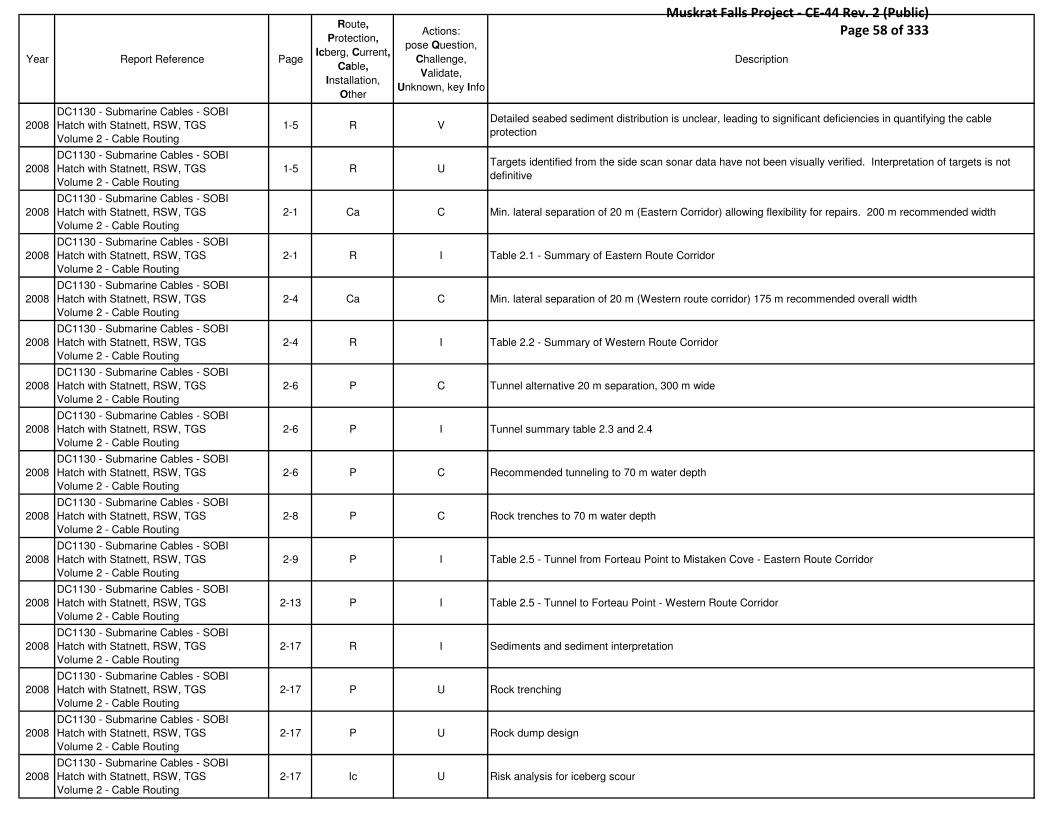
Year Report Reference Page
Route,
Protection,
Icberg, Current,
Cable,
Installation,
Other
Actions:
pose Question,
Challenge,
Validate,
Unknown, key Info
Description
2008
DC1130 - Submarine Cables - SOBI
Hatch with Statnett, RSW, TGS
Volume 2 - Cable Routing
1-5 R VDetailed seabed sediment distribution is unclear, leading to significant deficiencies in quantifying the cable
protection
2008
DC1130 - Submarine Cables - SOBI
Hatch with Statnett, RSW, TGS
Volume 2 - Cable Routing
1-5 R UTargets identified from the side scan sonar data have not been visually verified. Interpretation of targets is not
definitive
2008
DC1130 - Submarine Cables - SOBI
Hatch with Statnett, RSW, TGS
Volume 2 - Cable Routing
2-1 Ca C Min. lateral separation of 20 m (Eastern Corridor) allowing flexibility for repairs. 200 m recommended width
2008
DC1130 - Submarine Cables - SOBI
Hatch with Statnett, RSW, TGS
Volume 2 - Cable Routing
2-1 R I Table 2.1 - Summary of Eastern Route Corridor
2008
DC1130 - Submarine Cables - SOBI
Hatch with Statnett, RSW, TGS
Volume 2 - Cable Routing
2-4 Ca C Min. lateral separation of 20 m (Western route corridor) 175 m recommended overall width
2008
DC1130 - Submarine Cables - SOBI
Hatch with Statnett, RSW, TGS
Volume 2 - Cable Routing
2-4 R I Table 2.2 - Summary of Western Route Corridor
2008
DC1130 - Submarine Cables - SOBI
Hatch with Statnett, RSW, TGS
Volume 2 - Cable Routing
2-6 P C Tunnel alternative 20 m separation, 300 m wide
2008
DC1130 - Submarine Cables - SOBI
Hatch with Statnett, RSW, TGS
Volume 2 - Cable Routing
2-6 P I Tunnel summary table 2.3 and 2.4
2008
DC1130 - Submarine Cables - SOBI
Hatch with Statnett, RSW, TGS
Volume 2 - Cable Routing
2-6 P C Recommended tunneling to 70 m water depth
2008
DC1130 - Submarine Cables - SOBI
Hatch with Statnett, RSW, TGS
Volume 2 - Cable Routing
2-8 P C Rock trenches to 70 m water depth
2008
DC1130 - Submarine Cables - SOBI
Hatch with Statnett, RSW, TGS
Volume 2 - Cable Routing
2-9 P I Table 2.5 - Tunnel from Forteau Point to Mistaken Cove - Eastern Route Corridor
2008
DC1130 - Submarine Cables - SOBI
Hatch with Statnett, RSW, TGS
Volume 2 - Cable Routing
2-13 P I Table 2.5 - Tunnel to Forteau Point - Western Route Corridor
2008
DC1130 - Submarine Cables - SOBI
Hatch with Statnett, RSW, TGS
Volume 2 - Cable Routing
2-17 R I Sediments and sediment interpretation
2008
DC1130 - Submarine Cables - SOBI
Hatch with Statnett, RSW, TGS
Volume 2 - Cable Routing
2-17 P U Rock trenching
2008
DC1130 - Submarine Cables - SOBI
Hatch with Statnett, RSW, TGS
Volume 2 - Cable Routing
2-17 P U Rock dump design
2008
DC1130 - Submarine Cables - SOBI
Hatch with Statnett, RSW, TGS
Volume 2 - Cable Routing
2-17 Ic U Risk analysis for iceberg scour
Muskrat Falls Project - CE-44 Rev. 2 (Public) Page 58 of 333

Year Report Reference Page
Route,
Protection,
Icberg, Current,
Cable,
Installation,
Other
Actions:
pose Question,
Challenge,
Validate,
Unknown, key Info
Description
2008
DC1130 - Submarine Cables - SOBI
Hatch with Statnett, RSW, TGS
Volume 2 - Cable Routing
2-17 I U Shallow water cable installation
2008
DC1130 - Submarine Cables - SOBI
Hatch with Statnett, RSW, TGS
Volume 2 - Cable Routing
2-17 P C Tunnel routing
2008
DC1130 - Submarine Cables - SOBI
Hatch with Statnett, RSW, TGS
Volume 2 - Cable Routing
2-17 R U Ship traffic
2008
DC1130 - Submarine Cables - SOBI
Hatch with Statnett, RSW, TGS
Volume 2 - Cable Routing
2-17 P U Fishing activity
2008
DC1130 - Submarine Cables - SOBI
Hatch with Statnett, RSW, TGS
Volume 2 - Cable Routing
2-17 P C Discussions of rock dump size with fisherman
2008
DC1130 - Submarine Cables - SOBI
Hatch with Statnett, RSW, TGS
Volume 2 - Cable Routing
2-17 R U archaeological find procedure
2008
DC1130 - Submarine Cables - SOBI
Hatch with Statnett, RSW, TGS
Volume 2 - Cable Routing
2-17 R U Landfall construction plan
2008
DC1130 - Submarine Cables - SOBI
Hatch with Statnett, RSW, TGS
Volume 2 - Cable Routing
2-18 C C Need for full water column measurements at 15 min. intervals
2008
DC1130 - Submarine Cables - SOBI
Hatch with Statnett, RSW, TGS
Volume 2 - Cable Routing
3-1 R U Exclusion zones
2008
DC1130 - Submarine Cables - SOBI
Hatch with Statnett, RSW, TGS
Volume 2 - Cable Routing
3-1 R U Coldwater corals [discuss with Steve]
2008
DC1130 - Submarine Cables - SOBI
Hatch with Statnett, RSW, TGS
Volume 2 - Cable Routing
3-1 R V Ideal sediment is < 40 kPa for cable lay
2008
DC1130 - Submarine Cables - SOBI
Hatch with Statnett, RSW, TGS
Volume 2 - Cable Routing
3-1 P C Preferred trenching is water jetting
2008
DC1130 - Submarine Cables - SOBI
Hatch with Statnett, RSW, TGS
Volume 2 - Cable Routing
3-1 R U Protected natural reserves
2008
DC1130 - Submarine Cables - SOBI
Hatch with Statnett, RSW, TGS
Volume 2 - Cable Routing
3-4 P U Extent of near shore wave action
2008
DC1130 - Submarine Cables - SOBI
Hatch with Statnett, RSW, TGS
Volume 2 - Cable Routing
3-4 R U Seismic activity along fault lines - ground displacements
2008
DC1130 - Submarine Cables - SOBI
Hatch with Statnett, RSW, TGS
Volume 2 - Cable Routing
3-4 P V Slopes steeper than 15 degrees should be avoided for jetting operations
Muskrat Falls Project - CE-44 Rev. 2 (Public) Page 59 of 333

Year Report Reference Page
Route,
Protection,
Icberg, Current,
Cable,
Installation,
Other
Actions:
pose Question,
Challenge,
Validate,
Unknown, key Info
Description
2008
DC1130 - Submarine Cables - SOBI
Hatch with Statnett, RSW, TGS
Volume 2 - Cable Routing
3-4 P U Possible abrasion issues in shallow water
2008
DC1130 - Submarine Cables - SOBI
Hatch with Statnett, RSW, TGS
Volume 2 - Cable Routing
3-5 I I Vortex shedding and cycling drag at free spans - avoid!
2008
DC1130 - Submarine Cables - SOBI
Hatch with Statnett, RSW, TGS
Volume 2 - Cable Routing
3-5 I V In water depths less than 10 m, cable laying offshore vessels cannot operate
2008
DC1130 - Submarine Cables - SOBI
Hatch with Statnett, RSW, TGS
Volume 2 - Cable Routing
3-5 I I Inshore to be done with smaller spreads
2008
DC1130 - Submarine Cables - SOBI
Hatch with Statnett, RSW, TGS
Volume 2 - Cable Routing
3-5 R U Corals
2008
DC1130 - Submarine Cables - SOBI
Hatch with Statnett, RSW, TGS
Volume 2 - Cable Routing
3-5 Ca UThermal resistively - important factor in cable design. A survey task is to provide data regarding the thermal
resistively for impact into the cable design basis.
2008
DC1130 - Submarine Cables - SOBI
Hatch with Statnett, RSW, TGS
Volume 2 - Cable Routing
3-5 P U Trawl boards and beams [???]
2008
DC1130 - Submarine Cables - SOBI
Hatch with Statnett, RSW, TGS
Volume 2 - Cable Routing
3-5 P U Grapnels, anchors, and heavy deadweights
2008
DC1130 - Submarine Cables - SOBI
Hatch with Statnett, RSW, TGS
Volume 2 - Cable Routing
3-6 P C Recommended 1 m backfill over cable, hard ground 0.5 m over cable
2008
DC1130 - Submarine Cables - SOBI
Hatch with Statnett, RSW, TGS
Volume 2 - Cable Routing
3-6 P U Sinking vessels!
2008
DC1130 - Submarine Cables - SOBI
Hatch with Statnett, RSW, TGS
Volume 2 - Cable Routing
3-6 P U Anchor penetration
2008
DC1130 - Submarine Cables - SOBI
Hatch with Statnett, RSW, TGS
Volume 2 - Cable Routing
3-6 P Q Setup anchorage exclusion zone do-able?
2008
DC1130 - Submarine Cables - SOBI
Hatch with Statnett, RSW, TGS
Volume 2 - Cable Routing
3-6 P U Emergency ship grounding considerations
2008
DC1130 - Submarine Cables - SOBI
Hatch with Statnett, RSW, TGS
Volume 2 - Cable Routing
3-7 O U "Heavy Plant"?
2008
DC1130 - Submarine Cables - SOBI
Hatch with Statnett, RSW, TGS
Volume 2 - Cable Routing
3-7 P C "'disturbance of seabed down to several meters depth"
2008
DC1130 - Submarine Cables - SOBI
Hatch with Statnett, RSW, TGS
Volume 2 - Cable Routing
3-7 O U Oil and gas planned exploration
Muskrat Falls Project - CE-44 Rev. 2 (Public) Page 60 of 333

Year Report Reference Page
Route,
Protection,
Icberg, Current,
Cable,
Installation,
Other
Actions:
pose Question,
Challenge,
Validate,
Unknown, key Info
Description
2008
DC1130 - Submarine Cables - SOBI
Hatch with Statnett, RSW, TGS
Volume 2 - Cable Routing
3-7 I U port facilities and bridges
2008
DC1130 - Submarine Cables - SOBI
Hatch with Statnett, RSW, TGS
Volume 2 - Cable Routing
3-7 R U Outfalls
2008
DC1130 - Submarine Cables - SOBI
Hatch with Statnett, RSW, TGS
Volume 2 - Cable Routing
3-7 R V Any existing cables buried [later in the report it is stated that there are no cables buried in the straight]
2008
DC1130 - Submarine Cables - SOBI
Hatch with Statnett, RSW, TGS
Volume 2 - Cable Routing
3-7 Ca C
Cable - 2x water depth separation
Pipelines - 3x water depth
Telecable - 2km to be maintained for repeaters
2008
DC1130 - Submarine Cables - SOBI
Hatch with Statnett, RSW, TGS
Volume 2 - Cable Routing
3-7 Ca U Future cables
2008
DC1130 - Submarine Cables - SOBI
Hatch with Statnett, RSW, TGS
Volume 2 - Cable Routing
3-8 R V Wrecks older then 100 years are considered archaeological importance. Min. offset 100 m.
2008
DC1130 - Submarine Cables - SOBI
Hatch with Statnett, RSW, TGS
Volume 2 - Cable Routing
3-8 R V 500 m wreck offset, 100 m arch. Offset, 100 m large debris offset
2008
DC1130 - Submarine Cables - SOBI
Hatch with Statnett, RSW, TGS
Volume 2 - Cable Routing
3-8 R U Military activities and exclusion zones
2008
DC1130 - Submarine Cables - SOBI
Hatch with Statnett, RSW, TGS
Volume 2 - Cable Routing
3-8 O V Currently the Canadian legislation is working to be in accordance with UNCLOs
2008
DC1130 - Submarine Cables - SOBI
Hatch with Statnett, RSW, TGS
Volume 2 - Cable Routing
3-8 O U Mines???
2008
DC1130 - Submarine Cables - SOBI
Hatch with Statnett, RSW, TGS
Volume 2 - Cable Routing
3-8 O U Dump Sites??
2008
DC1130 - Submarine Cables - SOBI
Hatch with Statnett, RSW, TGS
Volume 2 - Cable Routing
4-1 R I Most geophysical data came from FJG 2007
2008
DC1130 - Submarine Cables - SOBI
Hatch with Statnett, RSW, TGS
Volume 2 - Cable Routing
4-1 P I
1970s methods
- bedrock tunnel beneath strait
- 2 bedrock …[check ref]
- lay cables in premade … [check ref]
2008
DC1130 - Submarine Cables - SOBI
Hatch with Statnett, RSW, TGS
Volume 2 - Cable Routing
4-1 R I
Bathy Resources
- FJG 2007 - Route Survey and Interpretation Report
- FJG 2007 - Desk top study
- FJG 2007 - Bathy recon survey
- AMEC Earth and Envi 2008
- CCORE 2007 Ice Scour Risk
- JW 2007 Strait of Belle Isle Constraint Mapping Report
Muskrat Falls Project - CE-44 Rev. 2 (Public) Page 61 of 333
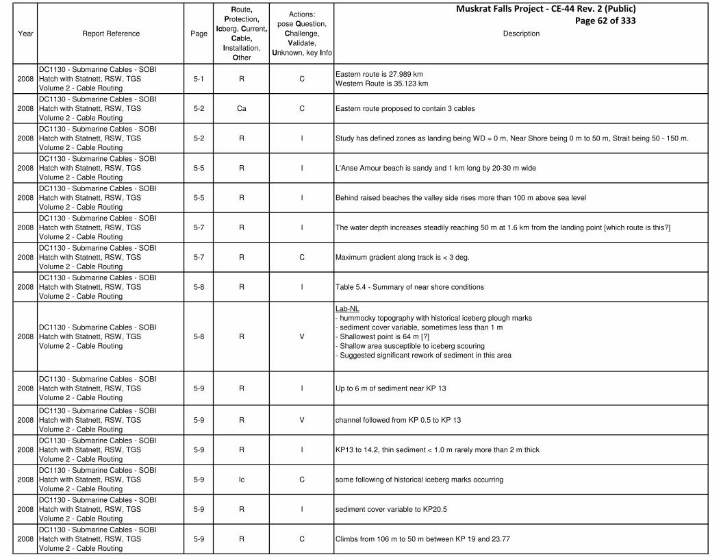
Year Report Reference Page
Route,
Protection,
Icberg, Current,
Cable,
Installation,
Other
Actions:
pose Question,
Challenge,
Validate,
Unknown, key Info
Description
2008
DC1130 - Submarine Cables - SOBI
Hatch with Statnett, RSW, TGS
Volume 2 - Cable Routing
5-1 R CEastern route is 27.989 km
Western Route is 35.123 km
2008
DC1130 - Submarine Cables - SOBI
Hatch with Statnett, RSW, TGS
Volume 2 - Cable Routing
5-2 Ca C Eastern route proposed to contain 3 cables
2008
DC1130 - Submarine Cables - SOBI
Hatch with Statnett, RSW, TGS
Volume 2 - Cable Routing
5-2 R I Study has defined zones as landing being WD = 0 m, Near Shore being 0 m to 50 m, Strait being 50 - 150 m.
2008
DC1130 - Submarine Cables - SOBI
Hatch with Statnett, RSW, TGS
Volume 2 - Cable Routing
5-5 R I L'Anse Amour beach is sandy and 1 km long by 20-30 m wide
2008
DC1130 - Submarine Cables - SOBI
Hatch with Statnett, RSW, TGS
Volume 2 - Cable Routing
5-5 R I Behind raised beaches the valley side rises more than 100 m above sea level
2008
DC1130 - Submarine Cables - SOBI
Hatch with Statnett, RSW, TGS
Volume 2 - Cable Routing
5-7 R I The water depth increases steadily reaching 50 m at 1.6 km from the landing point [which route is this?]
2008
DC1130 - Submarine Cables - SOBI
Hatch with Statnett, RSW, TGS
Volume 2 - Cable Routing
5-7 R C Maximum gradient along track is < 3 deg.
2008
DC1130 - Submarine Cables - SOBI
Hatch with Statnett, RSW, TGS
Volume 2 - Cable Routing
5-8 R I Table 5.4 - Summary of near shore conditions
2008
DC1130 - Submarine Cables - SOBI
Hatch with Statnett, RSW, TGS
Volume 2 - Cable Routing
5-8 R V
Lab-NL
- hummocky topography with historical iceberg plough marks
- sediment cover variable, sometimes less than 1 m
- Shallowest point is 64 m [?]
- Shallow area susceptible to iceberg scouring
- Suggested significant rework of sediment in this area
2008
DC1130 - Submarine Cables - SOBI
Hatch with Statnett, RSW, TGS
Volume 2 - Cable Routing
5-9 R I Up to 6 m of sediment near KP 13
2008
DC1130 - Submarine Cables - SOBI
Hatch with Statnett, RSW, TGS
Volume 2 - Cable Routing
5-9 R V channel followed from KP 0.5 to KP 13
2008
DC1130 - Submarine Cables - SOBI
Hatch with Statnett, RSW, TGS
Volume 2 - Cable Routing
5-9 R I KP13 to 14.2, thin sediment < 1.0 m rarely more than 2 m thick
2008
DC1130 - Submarine Cables - SOBI
Hatch with Statnett, RSW, TGS
Volume 2 - Cable Routing
5-9 Ic C some following of historical iceberg marks occurring
2008
DC1130 - Submarine Cables - SOBI
Hatch with Statnett, RSW, TGS
Volume 2 - Cable Routing
5-9 R I sediment cover variable to KP20.5
2008
DC1130 - Submarine Cables - SOBI
Hatch with Statnett, RSW, TGS
Volume 2 - Cable Routing
5-9 R C Climbs from 106 m to 50 m between KP 19 and 23.77
Muskrat Falls Project - CE-44 Rev. 2 (Public) Page 62 of 333

Year Report Reference Page
Route,
Protection,
Icberg, Current,
Cable,
Installation,
Other
Actions:
pose Question,
Challenge,
Validate,
Unknown, key Info
Description
2008
DC1130 - Submarine Cables - SOBI
Hatch with Statnett, RSW, TGS
Volume 2 - Cable Routing
5-9 R I Two steps in climb: HP 21.07 at 90m and 80 m at KP 22.2
2008
DC1130 - Submarine Cables - SOBI
Hatch with Statnett, RSW, TGS
Volume 2 - Cable Routing
5-9 R C Route corridor has been optimized to try and use as many areas of sediment as possible
2008
DC1130 - Submarine Cables - SOBI
Hatch with Statnett, RSW, TGS
Volume 2 - Cable Routing
5-9 R I 50 m isobath located at KP23.7 where bedrock is at the surface or under a thin lay deposit
2008
DC1130 - Submarine Cables - SOBI
Hatch with Statnett, RSW, TGS
Volume 2 - Cable Routing
5-9 R I Table 5.5 - Summary of conditions - SOBI
2008
DC1130 - Submarine Cables - SOBI
Hatch with Statnett, RSW, TGS
Volume 2 - Cable Routing
5-14 R I Table 5.6 - Summary of Conditions - Near Shore Mistaken Cove
2008
DC1130 - Submarine Cables - SOBI
Hatch with Statnett, RSW, TGS
Volume 2 - Cable Routing
5-14 R I Vertical bedrock steps 2m - 6m KP 23.776 - 26.996
2008
DC1130 - Submarine Cables - SOBI
Hatch with Statnett, RSW, TGS
Volume 2 - Cable Routing
5-14 R U "Sediment migration identified… may provide inadequate protection of installed cables"
2008
DC1130 - Submarine Cables - SOBI
Hatch with Statnett, RSW, TGS
Volume 2 - Cable Routing
5-15 R I Table 5.8 - Areas of Sediment Migration
2008
DC1130 - Submarine Cables - SOBI
Hatch with Statnett, RSW, TGS
Volume 2 - Cable Routing
5-15 R CNo excessive gradients have been found along the route (>15 deg), therefore it is not expected to encounter
Sediment stability hazard's.
2008
DC1130 - Submarine Cables - SOBI
Hatch with Statnett, RSW, TGS
Volume 2 - Cable Routing
5-15 R U Bedrock steps
2008
DC1130 - Submarine Cables - SOBI
Hatch with Statnett, RSW, TGS
Volume 2 - Cable Routing
5-15 R I Table 5.9 - Areas of bedrock bluffs
2008
DC1130 - Submarine Cables - SOBI
Hatch with Statnett, RSW, TGS
Volume 2 - Cable Routing
5-16 R I Table 5.10 Areas of Bedrock Outcrops
2008
DC1130 - Submarine Cables - SOBI
Hatch with Statnett, RSW, TGS
Volume 2 - Cable Routing
5-17 Ca V No thermal resistively measurements have been acquired
2008
DC1130 - Submarine Cables - SOBI
Hatch with Statnett, RSW, TGS
Volume 2 - Cable Routing
5-17 P I Trenchability assessed based on SBP interpretation and isopach chart
2008
DC1130 - Submarine Cables - SOBI
Hatch with Statnett, RSW, TGS
Volume 2 - Cable Routing
5-17 P CTable 5.12 - Trenchability - Eastern Route
e.g. KP 0.35-0.4, soil t is 0-2m = trenchable
2008
DC1130 - Submarine Cables - SOBI
Hatch with Statnett, RSW, TGS
Volume 2 - Cable Routing
5-21 R I Table 5.13 - SSS Targets +/- 10 m from Centerline
Muskrat Falls Project - CE-44 Rev. 2 (Public) Page 63 of 333
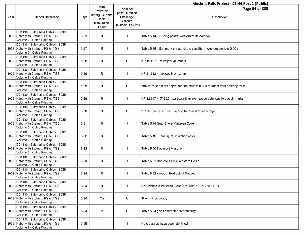
Year Report Reference Page
Route,
Protection,
Icberg, Current,
Cable,
Installation,
Other
Actions:
pose Question,
Challenge,
Validate,
Unknown, key Info
Description
2008
DC1130 - Submarine Cables - SOBI
Hatch with Statnett, RSW, TGS
Volume 2 - Cable Routing
5-23 R I Table 5.14 - Turning points, western route corridor
2008
DC1130 - Submarine Cables - SOBI
Hatch with Statnett, RSW, TGS
Volume 2 - Cable Routing
5-27 R I Table 5.16 - Summary of near shore condition - western corridor 0-50 m
2008
DC1130 - Submarine Cables - SOBI
Hatch with Statnett, RSW, TGS
Volume 2 - Cable Routing
5-28 R C KP 15.427 - Paleo plough marks
2008
DC1130 - Submarine Cables - SOBI
Hatch with Statnett, RSW, TGS
Volume 2 - Cable Routing
5-28 R I KP 21.912 - max depth of 124 m
2008
DC1130 - Submarine Cables - SOBI
Hatch with Statnett, RSW, TGS
Volume 2 - Cable Routing
5-28 R C maximize sediment depth and maintain min 600 m offset from easterly route
2008
DC1130 - Submarine Cables - SOBI
Hatch with Statnett, RSW, TGS
Volume 2 - Cable Routing
5-28 R I KP 22.847 - KP 25.5 - particularly uneven topography due to plough marks
2008
DC1130 - Submarine Cables - SOBI
Hatch with Statnett, RSW, TGS
Volume 2 - Cable Routing
5-28 R C KP 25.5 to KP 28.723 - routing for sediment coverage
2008
DC1130 - Submarine Cables - SOBI
Hatch with Statnett, RSW, TGS
Volume 2 - Cable Routing
5-31 R I Table 5.18 Near Shore Mistaken Cove
2008
DC1130 - Submarine Cables - SOBI
Hatch with Statnett, RSW, TGS
Volume 2 - Cable Routing
5-32 R I Table 5.19 - Landing pt, mistaken cove
2008
DC1130 - Submarine Cables - SOBI
Hatch with Statnett, RSW, TGS
Volume 2 - Cable Routing
5-32 R I Table 5.20 Sediment Migration
2008
DC1130 - Submarine Cables - SOBI
Hatch with Statnett, RSW, TGS
Volume 2 - Cable Routing
5-33 R I Table 5.21 Bedrock Bluffs, Western Route
2008
DC1130 - Submarine Cables - SOBI
Hatch with Statnett, RSW, TGS
Volume 2 - Cable Routing
5-34 R I Table 5.22 Areas of Bedrock at Seabed
2008
DC1130 - Submarine Cables - SOBI
Hatch with Statnett, RSW, TGS
Volume 2 - Cable Routing
5-34 R I Soil thickness between 0 and 1 m from KP 29.7 to KP 34
2008
DC1130 - Submarine Cables - SOBI
Hatch with Statnett, RSW, TGS
Volume 2 - Cable Routing
5-34 Ca U Thermal resistively
2008
DC1130 - Submarine Cables - SOBI
Hatch with Statnett, RSW, TGS
Volume 2 - Cable Routing
5-34 P C Table 5.24 gives estimated trenchability
2008
DC1130 - Submarine Cables - SOBI
Hatch with Statnett, RSW, TGS
Volume 2 - Cable Routing
5-38 I I No crossings have been identified
Muskrat Falls Project - CE-44 Rev. 2 (Public) Page 64 of 333

Year Report Reference Page
Route,
Protection,
Icberg, Current,
Cable,
Installation,
Other
Actions:
pose Question,
Challenge,
Validate,
Unknown, key Info
Description
2008
DC1130 - Submarine Cables - SOBI
Hatch with Statnett, RSW, TGS
Volume 2 - Cable Routing
5-39 R I Tunnel Route, Forteau Point to Western Corridor:
2008
DC1130 - Submarine Cables - SOBI
Hatch with Statnett, RSW, TGS
Volume 2 - Cable Routing
5-39 R I Joins route at KP 1.2, at 70 m water depth
2008
DC1130 - Submarine Cables - SOBI
Hatch with Statnett, RSW, TGS
Volume 2 - Cable Routing
5-39 R I Photo of Forteau Point
2008
DC1130 - Submarine Cables - SOBI
Hatch with Statnett, RSW, TGS
Volume 2 - Cable Routing
5-41 P C Yankee point tunnel proposal to carry cables to 70 m offshore
2008
DC1130 - Submarine Cables - SOBI
Hatch with Statnett, RSW, TGS
Volume 2 - Cable Routing
5-42 R C Table 5.27 - Borehole lay, Yankee Point
2008
DC1130 - Submarine Cables - SOBI
Hatch with Statnett, RSW, TGS
Volume 2 - Cable Routing
5-43 Ca C No thermal data for Forteau Point Tunnel route
2008
DC1130 - Submarine Cables - SOBI
Hatch with Statnett, RSW, TGS
Volume 2 - Cable Routing
5-43 P C Table 5.30 - Trechability data
2008
DC1130 - Submarine Cables - SOBI
Hatch with Statnett, RSW, TGS
Volume 2 - Cable Routing
6-1 R I Environmental conditions Overview
2008
DC1130 - Submarine Cables - SOBI
Hatch with Statnett, RSW, TGS
Volume 2 - Cable Routing
6-1 I V April to Sept. as working window
2008
DC1130 - Submarine Cables - SOBI
Hatch with Statnett, RSW, TGS
Volume 2 - Cable Routing
6-1 I V July to Sept. as optimal temp.
2008
DC1130 - Submarine Cables - SOBI
Hatch with Statnett, RSW, TGS
Volume 2 - Cable Routing
6-2 I I Wind Speeds - fig. 6.2
2008
DC1130 - Submarine Cables - SOBI
Hatch with Statnett, RSW, TGS
Volume 2 - Cable Routing
6-3 I I Fig. 6.3 - Monthly wind rose
2008
DC1130 - Submarine Cables - SOBI
Hatch with Statnett, RSW, TGS
Volume 2 - Cable Routing
6-3 I V Main wave directions are W and SW with height rarely greater than 3 m
2008
DC1130 - Submarine Cables - SOBI
Hatch with Statnett, RSW, TGS
Volume 2 - Cable Routing
6-3 C V Currents are greatest on Labrador coast and at surface
2008
DC1130 - Submarine Cables - SOBI
Hatch with Statnett, RSW, TGS
Volume 2 - Cable Routing
6-4 C V Highest currents speeds recorded are 5.1 kts at surface and 3.4 at bottom
2008
DC1130 - Submarine Cables - SOBI
Hatch with Statnett, RSW, TGS
Volume 2 - Cable Routing
6-4 I UCCORE report is thorough and attempts to model ice conditions. But, it predates survey so does not use latest
bathy data but relays on digi. Data from 1992 (Woodward)
Muskrat Falls Project - CE-44 Rev. 2 (Public) Page 65 of 333

Year Report Reference Page
Route,
Protection,
Icberg, Current,
Cable,
Installation,
Other
Actions:
pose Question,
Challenge,
Validate,
Unknown, key Info
Description
2008
DC1130 - Submarine Cables - SOBI
Hatch with Statnett, RSW, TGS
Volume 2 - Cable Routing
6-4 Ic C Table 6-5 - Iceberg grounding areas
2008
DC1130 - Submarine Cables - SOBI
Hatch with Statnett, RSW, TGS
Volume 2 - Cable Routing
6-4 Ic CNormally icebergs travel down Western channel of SOBI, grounding in water depths less than 70 m. Sometimes
icebergs travel north along eastern side
2008
DC1130 - Submarine Cables - SOBI
Hatch with Statnett, RSW, TGS
Volume 2 - Cable Routing
6-6 Ic I Table 6.2 - Plough Mark Scour Depths - 2 m greatest depth risk
2008
DC1130 - Submarine Cables - SOBI
Hatch with Statnett, RSW, TGS
Volume 2 - Cable Routing
6-7 Ic I Table 6.3 - Plough mark scour cover depths for shielded - non-shielded contact events
2008
DC1130 - Submarine Cables - SOBI
Hatch with Statnett, RSW, TGS
Volume 2 - Cable Routing
6-7 Ic C Pack-ice scour risk - no risk data analyzed previously
2008
DC1130 - Submarine Cables - SOBI
Hatch with Statnett, RSW, TGS
Volume 2 - Cable Routing
6-8 Ic I Table 6.4 - Ice Keel/ Cable contact events
2008
DC1130 - Submarine Cables - SOBI
Hatch with Statnett, RSW, TGS
Volume 2 - Cable Routing
6-8 R I Water temp - 9-10 deg surface max, to < 0 deg in winter
2008
DC1130 - Submarine Cables - SOBI
Hatch with Statnett, RSW, TGS
Volume 2 - Cable Routing
6-9 O I Water salinity
2008
DC1130 - Submarine Cables - SOBI
Hatch with Statnett, RSW, TGS
Volume 2 - Cable Routing
6-10 P I Main fisheries - lobster, scallops, shrimp, cod, capelin, Greenland halibut
2008
DC1130 - Submarine Cables - SOBI
Hatch with Statnett, RSW, TGS
Volume 2 - Cable Routing
6-10 P I Lobster - shallow water, spring, 8-10 weeks, more on Lab. Side
2008
DC1130 - Submarine Cables - SOBI
Hatch with Statnett, RSW, TGS
Volume 2 - Cable Routing
6-10 P I Shellfish - Iceland scallop dragging, 45-55 m, uses drags/dredges pulled along seabed
2008
DC1130 - Submarine Cables - SOBI
Hatch with Statnett, RSW, TGS
Volume 2 - Cable Routing
6-10 P I Shrimp - 150 m to 350 m, closest fishing is Esq. Channel
2008
DC1130 - Submarine Cables - SOBI
Hatch with Statnett, RSW, TGS
Volume 2 - Cable Routing
6-10 P U Shrimp trawling in the strait
2008
DC1130 - Submarine Cables - SOBI
Hatch with Statnett, RSW, TGS
Volume 2 - Cable Routing
6-10 P I Fig. 6.8 - Commercial Fishing Figures
2008
DC1130 - Submarine Cables - SOBI
Hatch with Statnett, RSW, TGS
Volume 2 - Cable Routing
6-12 P I Cod fishing - long-lining, gill nets (fixed anchors to seabed), cod traps with anchored boxes
2008
DC1130 - Submarine Cables - SOBI
Hatch with Statnett, RSW, TGS
Volume 2 - Cable Routing
6-13 I V No cables or pipelines that cross proposed routes
Muskrat Falls Project - CE-44 Rev. 2 (Public) Page 66 of 333

Year Report Reference Page
Route,
Protection,
Icberg, Current,
Cable,
Installation,
Other
Actions:
pose Question,
Challenge,
Validate,
Unknown, key Info
Description
2008
DC1130 - Submarine Cables - SOBI
Hatch with Statnett, RSW, TGS
Volume 2 - Cable Routing
6-14 R UWrecks and debris - 40 identified with limited position data, 1 has arch. Importance (HMS Raleigh - ANY
REMAINING EXPLOSIVES?)
2008
DC1130 - Submarine Cables - SOBI
Hatch with Statnett, RSW, TGS
Volume 2 - Cable Routing
6-14 R U May be unexploded ordinance lost in shallow water near wreck site
2008
DC1130 - Submarine Cables - SOBI
Hatch with Statnett, RSW, TGS
Volume 2 - Cable Routing
6-14 R U Historical assessment required for landfall sites
2008
DC1130 - Submarine Cables - SOBI
Hatch with Statnett, RSW, TGS
Volume 2 - Cable Routing
6-14 R V Any wrecks thought to be of arch importance require to be avoided by 100 m
2008
DC1130 - Submarine Cables - SOBI
Hatch with Statnett, RSW, TGS
Volume 2 - Cable Routing
6-14 R VThe arch. Responsible department has the right to request video inspection data and any other data related to the
route
2008
DC1130 - Submarine Cables - SOBI
Hatch with Statnett, RSW, TGS
Volume 2 - Cable Routing
6-14 R I Close liaison with archaeologists recommended from the get go
2008
DC1130 - Submarine Cables - SOBI
Hatch with Statnett, RSW, TGS
Volume 2 - Cable Routing
6-14 I U New legislation from UNLOSC requirements from Jan. 2008 may affect cable installation and operation
2008
DC1130 - Submarine Cables - SOBI
Hatch with Statnett, RSW, TGS
Volume 2 - Cable Routing
6-14 Ca U Details of cable between NB and PEI
2008
DC1130 - Submarine Cables - SOBI
Hatch with Statnett, RSW, TGS
Volume 2 - Cable Routing
7-1 R C Route selected based on sediment thickness, among other reasons
2008
DC1130 - Submarine Cables - SOBI
Hatch with Statnett, RSW, TGS
Volume 2 - Cable Routing
7-1 R I Table 7.1 Recommended Eastern Corridor
2008
DC1130 - Submarine Cables - SOBI
Hatch with Statnett, RSW, TGS
Volume 2 - Cable Routing
7-1 R C Routing (Plough marks, sediment, etc.)
2008
DC1130 - Submarine Cables - SOBI
Hatch with Statnett, RSW, TGS
Volume 2 - Cable Routing
7-3 R I Table 7.2 - Recommended Western Route Corridor
2008
DC1130 - Submarine Cables - SOBI
Hatch with Statnett, RSW, TGS
Volume 2 - Cable Routing
8-1 Ic URecommended to obtain more data for pack ice limits, iceberg patterns, currents, wind and waves, and water
temp.
2008
DC1130 - Submarine Cables - SOBI
Hatch with Statnett, RSW, TGS
Volume 2 - Cable Routing
8-1 Ic CRecommend CCORE Ice Scan report 2007 be revised and sampling devices be deployed to measure 12 month
data
2008
DC1130 - Submarine Cables - SOBI
Hatch with Statnett, RSW, TGS
Volume 2 - Cable Routing
8-1 R U no previously installed subsea lines in existence
2008
DC1130 - Submarine Cables - SOBI
Hatch with Statnett, RSW, TGS
Volume 2 - Cable Routing
8-1 O I no hydrocarbon concessions required
Muskrat Falls Project - CE-44 Rev. 2 (Public) Page 67 of 333

Year Report Reference Page
Route,
Protection,
Icberg, Current,
Cable,
Installation,
Other
Actions:
pose Question,
Challenge,
Validate,
Unknown, key Info
Description
2008
DC1130 - Submarine Cables - SOBI
Hatch with Statnett, RSW, TGS
Volume 2 - Cable Routing
8-1 P C Report recommends discussions with Fishing industry to understand rock protection size
2008
DC1130 - Submarine Cables - SOBI
Hatch with Statnett, RSW, TGS
Volume 2 - Cable Routing
8-1 P I Trawling and dredging are favored fishing methods
2008
DC1130 - Submarine Cables - SOBI
Hatch with Statnett, RSW, TGS
Volume 2 - Cable Routing
8-1 P I Recommend temp. protection until laid cables are covered to depth
2008
DC1130 - Submarine Cables - SOBI
Hatch with Statnett, RSW, TGS
Volume 2 - Cable Routing
8-2 I V Special notifications required for ship traffic during installation
2008
DC1130 - Submarine Cables - SOBI
Hatch with Statnett, RSW, TGS
Volume 2 - Cable Routing
8-2 I C minimum lay curve radius of 100 m
2008
DC1130 - Submarine Cables - SOBI
Hatch with Statnett, RSW, TGS
Volume 2 - Cable Routing
8-2 Ca C min separation of 20 m based on previous MI cable installation
2008
DC1130 - Submarine Cables - SOBI
Hatch with Statnett, RSW, TGS
Volume 2 - Cable Routing
8-2 Ca C 5 m min separation in trenches
2008
DC1130 - Submarine Cables - SOBI
Hatch with Statnett, RSW, TGS
Volume 2 - Cable Routing
8-2 R U EBSA requires special treatment
2008
DC1130 - Submarine Cables - SOBI
Hatch with Statnett, RSW, TGS
Volume 2 - Cable Routing
8-2 Ca UCompass deviation considerations which might affect cable separation we recommended to be in line with
accepted practice of max. acceptable deviation of 5 deg (Dutch, UK, German guidelines)
2008
DC1130 - Submarine Cables - SOBI
Hatch with Statnett, RSW, TGS
Volume 2 - Cable Routing
9-1 I U Use ROVs to lay cable between boulders and outcrops
2008
DC1130 - Submarine Cables - SOBI
Hatch with Statnett, RSW, TGS
Volume 2 - Cable Routing
9-1 I V ROV equipped cable layer?
2008
DC1130 - Submarine Cables - SOBI
Hatch with Statnett, RSW, TGS
Volume 2 - Cable Routing
9-1 I CFrequent stops during the laying with backing and re-laying are to be expected in order to verify that the cable is
appropriately positioned through seabed irregularities around rocks and boulders
2008
DC1130 - Submarine Cables - SOBI
Hatch with Statnett, RSW, TGS
Volume 2 - Cable Routing
9-1 R I High slope angles can lead to fluidization of sediment and exposure of cable
2008
DC1130 - Submarine Cables - SOBI
Hatch with Statnett, RSW, TGS
Volume 2 - Cable Routing
9-1 R IAreas of rock steps and bedrock bluffs are present and will require protection for the cable (minimized for route
selection).
2008
DC1130 - Submarine Cables - SOBI
Hatch with Statnett, RSW, TGS
Volume 2 - Cable Routing
9-2 C C Strong currents are likely to disrupt operation
2008
DC1130 - Submarine Cables - SOBI
Hatch with Statnett, RSW, TGS
Volume 2 - Cable Routing
9-2 I C Installation window is April to September
Muskrat Falls Project - CE-44 Rev. 2 (Public) Page 68 of 333

Year Report Reference Page
Route,
Protection,
Icberg, Current,
Cable,
Installation,
Other
Actions:
pose Question,
Challenge,
Validate,
Unknown, key Info
Description
2008
DC1130 - Submarine Cables - SOBI
Hatch with Statnett, RSW, TGS
Volume 2 - Cable Routing
9-2 P C Water trenching for protection
2008
DC1130 - Submarine Cables - SOBI
Hatch with Statnett, RSW, TGS
Volume 2 - Cable Routing
9-2 P I Ploughs can be used but aren't recommended
2008
DC1130 - Submarine Cables - SOBI
Hatch with Statnett, RSW, TGS
Volume 2 - Cable Routing
9-3 R U Has archaeological assessment of landfall sites been completed?
2008
DC1130 - Submarine Cables - SOBI
Hatch with Statnett, RSW, TGS
Volume 2 - Cable Routing
10-1 Ca C 3 cables in Eastern corridor and 2 in Western
2008
DC1130 - Submarine Cables - SOBI
Hatch with Statnett, RSW, TGS
Volume 2 - Cable Routing
10-1 R IGeotech samples recommended to be taken along the route to confirm sediment interpretation and establish
trenchability of sediments
2008
DC1130 - Submarine Cables - SOBI
Hatch with Statnett, RSW, TGS
Volume 2 - Cable Routing
10-1 P C Trenching depth variable between 1m and 3 m maximum (in areas of possible enhanced iceberg scour)
2008
DC1130 - Submarine Cables - SOBI
Hatch with Statnett, RSW, TGS
Volume 2 - Cable Routing
10-1 Ic U Re-calculated risk analysis CCORE 2007 for ice scour based on the MBES data collected in 2007
2008
DC1130 - Submarine Cables - SOBI
Hatch with Statnett, RSW, TGS
Volume 2 - Cable Routing
10-1 I UCable installation from small barges in Mistaken Cove (min. water depth for cable vessels is nominally 10 m found
2.442 km distance from the landing point)
2008
DC1130 - Submarine Cables - SOBI
Hatch with Statnett, RSW, TGS
Volume 2 - Cable Routing
10-1 R U Bedrock structure details
2008
DC1130 - Submarine Cables - SOBI
Hatch with Statnett, RSW, TGS
Volume 2 - Cable Routing
10-1 R I App. A: Route Position Listings
2008
DC1130 - Submarine Cables - SOBI
Hatch with Statnett, RSW, TGS
Volume 2 - Cable Routing
10-1 R I App. B: Long. Profiles
2008
DC1130 - Submarine Cables - SOBI
Hatch with Statnett, RSW, TGS
Volume 2 - Cable Routing
10-1 R C App. C: SSS Target Listings (Anything useful here??)
2008
DC1130 - Submarine Cables - SOBI
Hatch with Statnett, RSW, TGS
Volume 2 - Cable Routing
10-1 R I App. D: Grab sample listings
2008
DC1130 - Submarine Cables - SOBI
Hatch with Statnett, RSW, TGS
Volume 2 - Cable Routing
10-1 R I App. E: Photographic Listings
2008
DC1130 - Submarine Cables - SOBI
Hatch with Statnett, RSW, TGS
Volume 2 - Cable Routing
10-1 P I App. F: Fishing Equipment
2008
DC1130 - Submarine Cables - SOBI
Hatch with Statnett, RSW, TGS
Volume 3 - Design, Method, Cost and Plan
1-1 Ca C Principle reason for two corridors is to reduce possibility of simultaneous failure of cables
Muskrat Falls Project - CE-44 Rev. 2 (Public) Page 69 of 333

Year Report Reference Page
Route,
Protection,
Icberg, Current,
Cable,
Installation,
Other
Actions:
pose Question,
Challenge,
Validate,
Unknown, key Info
Description
2008
DC1130 - Submarine Cables - SOBI
Hatch with Statnett, RSW, TGS
Volume 3 - Design, Method, Cost and Plan
2-1 Ca I Table 2.1 - Pole currents for various voltage levels
2008
DC1130 - Submarine Cables - SOBI
Hatch with Statnett, RSW, TGS
Volume 3 - Design, Method, Cost and Plan
2-1 Ca V Conductor calcs done with 12 deg C. as acceptable temp. drop over insulation
2008
DC1130 - Submarine Cables - SOBI
Hatch with Statnett, RSW, TGS
Volume 3 - Design, Method, Cost and Plan
2-1 Ca I Capacity calcs done based on IEC 60287 standard
2008
DC1130 - Submarine Cables - SOBI
Hatch with Statnett, RSW, TGS
Volume 3 - Design, Method, Cost and Plan
2-1 Ca IThermal pre-conditions: burial depth is 3 m, separation of 5 m, soil temp at landfall is 12 deg C and max conductor
temp. is 55 deg C
2008
DC1130 - Submarine Cables - SOBI
Hatch with Statnett, RSW, TGS
Volume 3 - Design, Method, Cost and Plan
2-1 Ca V Insulation in a MI cable is not pressurized and cavities may form during cooling after a load drop
2008
DC1130 - Submarine Cables - SOBI
Hatch with Statnett, RSW, TGS
Volume 3 - Design, Method, Cost and Plan
2-2 Ca I Table 2.2 and 2.3 - Cable Properties as a function of Voltage
2008
DC1130 - Submarine Cables - SOBI
Hatch with Statnett, RSW, TGS
Volume 3 - Design, Method, Cost and Plan
2-2 Ca ISCOF - self-contained oil filled - impregnated with very low viscosity oil to enable flow along the cable to and from
pressurized oil expansion reservoirs at each end
2008
DC1130 - Submarine Cables - SOBI
Hatch with Statnett, RSW, TGS
Volume 3 - Design, Method, Cost and Plan
2-3 Ca I Availability for cable repair in SOBI may be limited due to physical environment.
2008
DC1130 - Submarine Cables - SOBI
Hatch with Statnett, RSW, TGS
Volume 3 - Design, Method, Cost and Plan
2-3 Ca I In the case of failure, the cable may leak oil for a long period until a repair operation can start
2008
DC1130 - Submarine Cables - SOBI
Hatch with Statnett, RSW, TGS
Volume 3 - Design, Method, Cost and Plan
2-3 Ca I To avoid destructive water intrusion, oil reservoirs have to contain large quantities of oil
2008
DC1130 - Submarine Cables - SOBI
Hatch with Statnett, RSW, TGS
Volume 3 - Design, Method, Cost and Plan
2-3 Ca C Oil leaks may be an environmental problem
2008
DC1130 - Submarine Cables - SOBI
Hatch with Statnett, RSW, TGS
Volume 3 - Design, Method, Cost and Plan
2-3 Ca I Table 2.4 - Properties of SCOF cable - Generally bigger and heavier than MI
Muskrat Falls Project - CE-44 Rev. 2 (Public) Page 70 of 333

Year Report Reference Page
Route,
Protection,
Icberg, Current,
Cable,
Installation,
Other
Actions:
pose Question,
Challenge,
Validate,
Unknown, key Info
Description
2008
DC1130 - Submarine Cables - SOBI
Hatch with Statnett, RSW, TGS
Volume 3 - Design, Method, Cost and Plan
3-1 P U Otter/trawl boards
2008
DC1130 - Submarine Cables - SOBI
Hatch with Statnett, RSW, TGS
Volume 3 - Design, Method, Cost and Plan
3-1 R I Table 3.1 - Eastern Route Sections
2008
DC1130 - Submarine Cables - SOBI
Hatch with Statnett, RSW, TGS
Volume 3 - Design, Method, Cost and Plan
3-4 R I Table 3.2 - Western Route Sections
2008
DC1130 - Submarine Cables - SOBI
Hatch with Statnett, RSW, TGS
Volume 3 - Design, Method, Cost and Plan
3-6 R I Routing with Tunnel on Both Sides - Table 3.3 - Eastern Route Sections
2008
DC1130 - Submarine Cables - SOBI
Hatch with Statnett, RSW, TGS
Volume 3 - Design, Method, Cost and Plan
3-8 R I Table 3.4 - Western Route Sections
2008
DC1130 - Submarine Cables - SOBI
Hatch with Statnett, RSW, TGS
Volume 3 - Design, Method, Cost and Plan
4-1 I U Transition Compounds
2008
DC1130 - Submarine Cables - SOBI
Hatch with Statnett, RSW, TGS
Volume 3 - Design, Method, Cost and Plan
4-1 I C Indoor transition compounds cost more (source???)
2008
DC1130 - Submarine Cables - SOBI
Hatch with Statnett, RSW, TGS
Volume 3 - Design, Method, Cost and Plan
4-1 I C Transition compounds assumed to be 400 m from shoreline on Lab. Side, and 600 m from shoreline on NL side
2008
DC1130 - Submarine Cables - SOBI
Hatch with Statnett, RSW, TGS
Volume 3 - Design, Method, Cost and Plan
5-1 P U Extent of trawling in region
2008
DC1130 - Submarine Cables - SOBI
Hatch with Statnett, RSW, TGS
Volume 3 - Design, Method, Cost and Plan
5-1 Ic C Suggested that iceberg risk is limited to < 70 m
2008
DC1130 - Submarine Cables - SOBI
Hatch with Statnett, RSW, TGS
Volume 3 - Design, Method, Cost and Plan
5-1 P C "Protection against emergency anchoring operations can normally not be obtained by burial only"
2008
DC1130 - Submarine Cables - SOBI
Hatch with Statnett, RSW, TGS
Volume 3 - Design, Method, Cost and Plan
5-1 P C Water jet trenching
Muskrat Falls Project - CE-44 Rev. 2 (Public) Page 71 of 333

Year Report Reference Page
Route,
Protection,
Icberg, Current,
Cable,
Installation,
Other
Actions:
pose Question,
Challenge,
Validate,
Unknown, key Info
Description
2008
DC1130 - Submarine Cables - SOBI
Hatch with Statnett, RSW, TGS
Volume 3 - Design, Method, Cost and Plan
5-1 P v Limestone/soft rock has been previously excavated to 3 m
2008
DC1130 - Submarine Cables - SOBI
Hatch with Statnett, RSW, TGS
Volume 3 - Design, Method, Cost and Plan
5-2 R I Rock is grey and brown dolostone, 50% dolomite
2008
DC1130 - Submarine Cables - SOBI
Hatch with Statnett, RSW, TGS
Volume 3 - Design, Method, Cost and Plan
5-2 R I Inside land on NL side is mostly boggy
2008
DC1130 - Submarine Cables - SOBI
Hatch with Statnett, RSW, TGS
Volume 3 - Design, Method, Cost and Plan
5-2 R I Yankee point borehole 74-B-D1
2008
DC1130 - Submarine Cables - SOBI
Hatch with Statnett, RSW, TGS
Volume 3 - Design, Method, Cost and Plan
5-2 R I Dolomite down to about 73 m
2008
DC1130 - Submarine Cables - SOBI
Hatch with Statnett, RSW, TGS
Volume 3 - Design, Method, Cost and Plan
5-3 R I Pt. Amour diamond core (74-B-D2)
2008
DC1130 - Submarine Cables - SOBI
Hatch with Statnett, RSW, TGS
Volume 3 - Design, Method, Cost and Plan
5-3 R IAt Point Amour there are 27 m with interbedded limestone (dolostone) and shale that belongs to the Forteau
Formation
2008
DC1130 - Submarine Cables - SOBI
Hatch with Statnett, RSW, TGS
Volume 3 - Design, Method, Cost and Plan
5-3 P C "Tunneling from land and out under the seafloor is a well-proven technique"
2008
DC1130 - Submarine Cables - SOBI
Hatch with Statnett, RSW, TGS
Volume 3 - Design, Method, Cost and Plan
5-4 I C "Recommend that the gradient be no deeper than 12%"
2008
DC1130 - Submarine Cables - SOBI
Hatch with Statnett, RSW, TGS
Volume 3 - Design, Method, Cost and Plan
5-4 P C 20 m^2 cross section for tunnel
2008
DC1130 - Submarine Cables - SOBI
Hatch with Statnett, RSW, TGS
Volume 3 - Design, Method, Cost and Plan
5-4 P V Cable jointing chamber can be sealed off and pumped dry
2008
DC1130 - Submarine Cables - SOBI
Hatch with Statnett, RSW, TGS
Volume 3 - Design, Method, Cost and Plan
5-4 P V Preferred drilling of micro tunnels is upwards
Muskrat Falls Project - CE-44 Rev. 2 (Public) Page 72 of 333

Year Report Reference Page
Route,
Protection,
Icberg, Current,
Cable,
Installation,
Other
Actions:
pose Question,
Challenge,
Validate,
Unknown, key Info
Description
2008
DC1130 - Submarine Cables - SOBI
Hatch with Statnett, RSW, TGS
Volume 3 - Design, Method, Cost and Plan
5-4 P C One or two spare tunnels should be drilled as contingency
2008
DC1130 - Submarine Cables - SOBI
Hatch with Statnett, RSW, TGS
Volume 3 - Design, Method, Cost and Plan
5-4 P C Micro tunnels to have diameter of 300-400 mm
2008
DC1130 - Submarine Cables - SOBI
Hatch with Statnett, RSW, TGS
Volume 3 - Design, Method, Cost and Plan
5-4 P C Table 5.4.3 - Water Jet Trenching
2008
DC1130 - Submarine Cables - SOBI
Hatch with Statnett, RSW, TGS
Volume 3 - Design, Method, Cost and Plan
5-4 P CMicro tunnels to be laid with steel tubes. If rock is poor quality, micro tunnels have to be installed during drilling.
Technology not yet fully developed.
2008
DC1130 - Submarine Cables - SOBI
Hatch with Statnett, RSW, TGS
Volume 3 - Design, Method, Cost and Plan
5-4 P U Technology anticipated to be commercially viable in 2 to 3 years.
2008
DC1130 - Submarine Cables - SOBI
Hatch with Statnett, RSW, TGS
Volume 3 - Design, Method, Cost and Plan
5-6 P U Use subsea excavator for rock trenching
2008
DC1130 - Submarine Cables - SOBI
Hatch with Statnett, RSW, TGS
Volume 3 - Design, Method, Cost and Plan
5-6 P I Only good to 15 Mpa
2008
DC1130 - Submarine Cables - SOBI
Hatch with Statnett, RSW, TGS
Volume 3 - Design, Method, Cost and Plan
5-6 P Q Which unit??? Www.scanmudring.no
2008
DC1130 - Submarine Cables - SOBI
Hatch with Statnett, RSW, TGS
Volume 3 - Design, Method, Cost and Plan
5-6 I C 20-70 m - offshore construction vessel with crane and winch capacity
2008
DC1130 - Submarine Cables - SOBI
Hatch with Statnett, RSW, TGS
Volume 3 - Design, Method, Cost and Plan
5-6 I C 2 m to 20 m - barge and mobile crane
2008
DC1130 - Submarine Cables - SOBI
Hatch with Statnett, RSW, TGS
Volume 3 - Design, Method, Cost and Plan
5-6 P C Table 5.2 - rock trenching lengths
2008
DC1130 - Submarine Cables - SOBI
Hatch with Statnett, RSW, TGS
Volume 3 - Design, Method, Cost and Plan
5-10 P C Lay in concrete Culverts or use sand protection with rock fill
Muskrat Falls Project - CE-44 Rev. 2 (Public) Page 73 of 333

Year Report Reference Page
Route,
Protection,
Icberg, Current,
Cable,
Installation,
Other
Actions:
pose Question,
Challenge,
Validate,
Unknown, key Info
Description
2008
DC1130 - Submarine Cables - SOBI
Hatch with Statnett, RSW, TGS
Volume 3 - Design, Method, Cost and Plan
5-10 C C Uncertain whether this can be done to currents
2008
DC1130 - Submarine Cables - SOBI
Hatch with Statnett, RSW, TGS
Volume 3 - Design, Method, Cost and Plan
5-10 Ic U Iceberg impact on concrete culverts
2008
DC1130 - Submarine Cables - SOBI
Hatch with Statnett, RSW, TGS
Volume 3 - Design, Method, Cost and Plan
5-10 P C Micro tunneling, plug application "Usually done" but yet technology is not developed??
2008
DC1130 - Submarine Cables - SOBI
Hatch with Statnett, RSW, TGS
Volume 3 - Design, Method, Cost and Plan
5-11 Ca C "Stats show cables that are installed have high reliability"
2008
DC1130 - Submarine Cables - SOBI
Hatch with Statnett, RSW, TGS
Volume 3 - Design, Method, Cost and Plan
6-1 I C There are only 2-3 purpose built cable installation vessels
2008
DC1130 - Submarine Cables - SOBI
Hatch with Statnett, RSW, TGS
Volume 3 - Design, Method, Cost and Plan
6-1 I U Tug requirements
2008
DC1130 - Submarine Cables - SOBI
Hatch with Statnett, RSW, TGS
Volume 3 - Design, Method, Cost and Plan
6-5 I IInstallation analyses will be executed covering areas of cable installation work that requires analyses and
computation. These analyses will be cased on governing documents and industry practice
2008
DC1130 - Submarine Cables - SOBI
Hatch with Statnett, RSW, TGS
Volume 3 - Design, Method, Cost and Plan
6-5 R U Detailed route survey
2008
DC1130 - Submarine Cables - SOBI
Hatch with Statnett, RSW, TGS
Volume 3 - Design, Method, Cost and Plan
6-5 Ca V Estimated loading for 2-3 cables is 6-7 days
2008
DC1130 - Submarine Cables - SOBI
Hatch with Statnett, RSW, TGS
Volume 3 - Design, Method, Cost and Plan
6-5 I V 18 days from Scandinavia to SOBI
2008
DC1130 - Submarine Cables - SOBI
Hatch with Statnett, RSW, TGS
Volume 3 - Design, Method, Cost and Plan
6-5 I C Need 30-35 T bollard pull tug
2008
DC1130 - Submarine Cables - SOBI
Hatch with Statnett, RSW, TGS
Volume 3 - Design, Method, Cost and Plan
6-7 Ca U Cable pull-in arrangement
Muskrat Falls Project - CE-44 Rev. 2 (Public) Page 74 of 333

Year Report Reference Page
Route,
Protection,
Icberg, Current,
Cable,
Installation,
Other
Actions:
pose Question,
Challenge,
Validate,
Unknown, key Info
Description
2008
DC1130 - Submarine Cables - SOBI
Hatch with Statnett, RSW, TGS
Volume 3 - Design, Method, Cost and Plan
6-8 I I ROV to monitor cable touchdown
2008
DC1130 - Submarine Cables - SOBI
Hatch with Statnett, RSW, TGS
Volume 3 - Design, Method, Cost and Plan
6-8 I C Cable laying system called Capjet by Nexxans
2008
DC1130 - Submarine Cables - SOBI
Hatch with Statnett, RSW, TGS
Volume 3 - Design, Method, Cost and Plan
6-9 Ca U Cable pull-in at Yankee Point - sensitivity of cable in water
2008
DC1130 - Submarine Cables - SOBI
Hatch with Statnett, RSW, TGS
Volume 3 - Design, Method, Cost and Plan
7-1 Ca U Time for replacement delivery
2008
DC1130 - Submarine Cables - SOBI
Hatch with Statnett, RSW, TGS
Volume 3 - Design, Method, Cost and Plan
7-1 Ca U Spares requirements
2008
DC1130 - Submarine Cables - SOBI
Hatch with Statnett, RSW, TGS
Volume 3 - Design, Method, Cost and Plan
7-1 Ca C Sufficient spares to serve two repairs
2008
DC1130 - Submarine Cables - SOBI
Hatch with Statnett, RSW, TGS
Volume 3 - Design, Method, Cost and Plan
7-1 P I An anchor hitting an unburied cable can damage up to 800 m as seen in Scandinavia
2008
DC1130 - Submarine Cables - SOBI
Hatch with Statnett, RSW, TGS
Volume 3 - Design, Method, Cost and Plan
7-1 Ca U Number of repair joints required
2008
DC1130 - Submarine Cables - SOBI
Hatch with Statnett, RSW, TGS
Volume 3 - Design, Method, Cost and Plan
7-1 Ca V Terminations may require up to 6 months delivery
2008
DC1130 - Submarine Cables - SOBI
Hatch with Statnett, RSW, TGS
Volume 3 - Design, Method, Cost and Plan
7-1 Ca U Repair joint availability
2008
DC1130 - Submarine Cables - SOBI
Hatch with Statnett, RSW, TGS
Volume 3 - Design, Method, Cost and Plan
7-1 Ca I Recommended repair preparedness plan and repair procedure to be pary of supply contract
2008
DC1130 - Submarine Cables - SOBI
Hatch with Statnett, RSW, TGS
Volume 3 - Design, Method, Cost and Plan
7-1 P I Rock removal equipment: Scanmudring, Five Oceans Services, Van Oord
Muskrat Falls Project - CE-44 Rev. 2 (Public) Page 75 of 333

Year Report Reference Page
Route,
Protection,
Icberg, Current,
Cable,
Installation,
Other
Actions:
pose Question,
Challenge,
Validate,
Unknown, key Info
Description
2008
DC1130 - Submarine Cables - SOBI
Hatch with Statnett, RSW, TGS
Volume 3 - Design, Method, Cost and Plan
8-1 P I Rock costs used on Norned Cable
2008
DC1130 - Submarine Cables - SOBI
Hatch with Statnett, RSW, TGS
Volume 3 - Design, Method, Cost and Plan
8-1 P V Rock trenching costs from Scanmudring - They have worked in NL
2008
DC1130 - Submarine Cables - SOBI
Hatch with Statnett, RSW, TGS
Volume 3 - Design, Method, Cost and Plan
8-1 P I Tunneling costs based on Norwegian experience
2008
DC1130 - Submarine Cables - SOBI
Hatch with Statnett, RSW, TGS
Volume 3 - Design, Method, Cost and Plan
8-1 Ca I Currently a supplier's market for cables
2008
DC1130 - Submarine Cables - SOBI
Hatch with Statnett, RSW, TGS
Volume 3 - Design, Method, Cost and Plan
8-1 Ca V Factories fully loaded for next few years
2008
DC1130 - Submarine Cables - SOBI
Hatch with Statnett, RSW, TGS
Volume 3 - Design, Method, Cost and Plan
8-1 Ca V Costs of cables increase 5-10%/year
2008
DC1130 - Submarine Cables - SOBI
Hatch with Statnett, RSW, TGS
Volume 3 - Design, Method, Cost and Plan
8-1 Ca V New material costs increased by 25% last year…
2008
DC1130 - Submarine Cables - SOBI
Hatch with Statnett, RSW, TGS
Volume 3 - Design, Method, Cost and Plan
8-2 P I Protection assumed at all route sections and at water depths greater than 70 m
2008
DC1130 - Submarine Cables - SOBI
Hatch with Statnett, RSW, TGS
Volume 3 - Design, Method, Cost and Plan
8-2 P C Estimated volume is 40,000 m^3 for five cables
2008
DC1130 - Submarine Cables - SOBI
Hatch with Statnett, RSW, TGS
Volume 3 - Design, Method, Cost and Plan
8-2 P C Assured suitable facilities for rock loading within 4 hours steam
2008
DC1130 - Submarine Cables - SOBI
Hatch with Statnett, RSW, TGS
Volume 3 - Design, Method, Cost and Plan
8-2 Ca I Table 8.1 - Cost estimate summary for SOBI Hvdc cables
2008
DC1130 - Submarine Cables - SOBI
Hatch with Statnett, RSW, TGS
Volume 3 - Design, Method, Cost and Plan
8-3 P V Cost increase for tunnel over Rock Trenches is $40 million
Muskrat Falls Project - CE-44 Rev. 2 (Public) Page 76 of 333

Year Report Reference Page
Route,
Protection,
Icberg, Current,
Cable,
Installation,
Other
Actions:
pose Question,
Challenge,
Validate,
Unknown, key Info
Description
2008
DC1130 - Submarine Cables - SOBI
Hatch with Statnett, RSW, TGS
Volume 3 - Design, Method, Cost and Plan
8-3 P C Water jetting assumed over 13 km. To use rock dumping instead, it would cost $17 M more.
2008
DC1130 - Submarine Cables - SOBI
Hatch with Statnett, RSW, TGS
Volume 3 - Design, Method, Cost and Plan
9-1 Ca V European Suppliers Capacity: Nexxans, 250k/year, ABB 300 k/year, Prysmian, 400k/year
2008
DC1130 - Submarine Cables - SOBI
Hatch with Statnett, RSW, TGS
Volume 3 - Design, Method, Cost and Plan
9-1 Ca V Japanese are more suited for manufacturing oil-filled cables than MI
2008
DC1130 - Submarine Cables - SOBI
Hatch with Statnett, RSW, TGS
Volume 3 - Design, Method, Cost and Plan
9-1 Ca I Facilities may be upgraded to suit this kind of production
2008
DC1130 - Submarine Cables - SOBI
Hatch with Statnett, RSW, TGS
Volume 3 - Design, Method, Cost and Plan
9-1 Ca I Nexxans has in the last year operated the paper-insulated cable facilities in VISCAS factory in Japan
2008
DC1130 - Submarine Cables - SOBI
Hatch with Statnett, RSW, TGS
Volume 3 - Design, Method, Cost and Plan
9-1 Ca I Manufacturing schedule based on two parallel lines/impregnating vessels available continuously for 14-16 months
2008
DC1130 - Submarine Cables - SOBI
Hatch with Statnett, RSW, TGS
Volume 3 - Design, Method, Cost and Plan
9-1 Ca V If type testing is required, cable would be ready in 26-28 months.
2008
DC1130 - Submarine Cables - SOBI
Hatch with Statnett, RSW, TGS
Volume 3 - Design, Method, Cost and Plan
9-1 Ca I Recommended to include at least limited verification type tests of cable and joints
2008
DC1130 - Submarine Cables - SOBI
Hatch with Statnett, RSW, TGS
Volume 3 - Design, Method, Cost and Plan
9-1 Ca C Both cable alternatives will require two laying campaigns
2008
DC1130 - Submarine Cables - SOBI
Hatch with Statnett, RSW, TGS
Volume 3 - Design, Method, Cost and Plan
9-1 Ca CStatnett project: delivery of 130 km, 450 Kv HVdc cable, 90 k of which was land based. To achieve 2014
installation, commitments to manufacturing need to be made around 2008. Manufacturing time??
2008
DC1130 - Submarine Cables - SOBI
Hatch with Statnett, RSW, TGS
Volume 3 - Design, Method, Cost and Plan
9-1 I U Vessel availability
2008
DC1130 - Submarine Cables - SOBI
Hatch with Statnett, RSW, TGS
Volume 3 - Design, Method, Cost and Plan
9-1 Ca I App. A: Cross sections
Muskrat Falls Project - CE-44 Rev. 2 (Public) Page 77 of 333

Year Report Reference Page
Route,
Protection,
Icberg, Current,
Cable,
Installation,
Other
Actions:
pose Question,
Challenge,
Validate,
Unknown, key Info
Description
2008
DC1130 - Submarine Cables - SOBI
Hatch with Statnett, RSW, TGS
Volume 3 - Design, Method, Cost and Plan
9-1 Ca I App. B: Transition Compound
2008
DC1130 - Submarine Cables - SOBI
Hatch with Statnett, RSW, TGS
Volume 3 - Design, Method, Cost and Plan
9-1 O I App. C: Project Schedules
2008
DC1130 - Submarine Cables - SOBI
Hatch with Statnett, RSW, TGS
Volume 3 - Design, Method, Cost and Plan
9-1 O I App. D: Cost Estimate
2008
DC1132 - Fugro Desktop Study - Appendix
B
Ice Scour Risk in Straight…
Section 2.2.1 - Last Paragraph - " Since the
avaliable date…..are limited and not
suitable…"
2-2 I Q
What data will be required to generate mean drift speeds?
How do we get this data?
How long will it take to get this data?
Is there benefit in getting this data?
2008
DC1132 - Fugro Desktop Study - Appendix
B
Ice Scour Risk in Straight…
Section 2.2.2 - Iceberg Density
2-3 Ic Q
Should we use the degree square for which the crossing will take place and not reduce the density by averaging it
with the adjoining square that is only 25% of it's value? This would result in more conservertative numbers.
Was there any consideration to bathymetric sheilding when using the average?
2008
DC1132 - Fugro Desktop Study - Appendix
B
Ice Scour Risk in Straight…
Section 2.2.2 - Iceberg Density
2-3 Ic IQuote - "This is approximately 20 times higher than the iceberg density in the Jeanne d'arc region of the grand
banks"
2008
DC1132 - Fugro Desktop Study - Appendix
B
Ice Scour Risk in Straight…
Section 2.2.2 - Iceberg Density
2-3 Ic QWhat is the Standare Deviation for average iceberg density? i.e. What is a bad year and what was the worst year
recorded?
2008
DC1132 - Fugro Desktop Study - Appendix
B
Ice Scour Risk in Straight…
Section 2.2.2 - Iceberg Density
2-3 Ic QCan we review these numbers including recent data up to and including 2009-2010 ice season?
Are there any Trends noticed in ice density? Are the densities increasing. Decreasing, or remaining the same?
2008
DC1132 - Fugro Desktop Study - Appendix
B
Ice Scour Risk in Straight…
Section 2.2.5 - Iceberg Drift Speed
2-8 Ic QStatement = " Since a grounded Iceberg cannot ground a second time…"
Question - Why not?
2008
DC1132 - Fugro Desktop Study - Appendix
B
Ice Scour Risk in Straight…
Section 2.3 - Modeled Grounding Rates
2-9 Ic Q
Statement = " It should be noted that ….model….does not account for mathymetric effect."
Question - Why not?
Question - How would data change if it did reflect sheilding?
2008
DC1132 - Fugro Desktop Study - Appendix
B
Ice Scour Risk in Straight…
Section 3.4 - contact Frequency and Cover
Depth
3-2 Ic Q
Statement = " the analysis required to evaluate additional clearance..."
Question - Can C-Core Do this?
Question - If so, what infromation is required to complete the calculations?
Muskrat Falls Project - CE-44 Rev. 2 (Public) Page 78 of 333

Year Report Reference Page
Route,
Protection,
Icberg, Current,
Cable,
Installation,
Other
Actions:
pose Question,
Challenge,
Validate,
Unknown, key Info
Description
2008
DC1132 - Fugro Desktop Study - Appendix
B
Ice Scour Risk in Straight…
Section 3.4 - contact Frequency and Cover
Depth
3-2 Ic Q
Continued……….
Question - Is this calculation based on established principles, or is it R&D
Question - Are there guidelines or a basis to cunduct these calculations for burried Cable (apposed to a rigid pipe)
2008
DC1132 - Fugro Desktop Study - Appendix
B
Ice Scour Risk in Straight…
Section 3.4 - contact Frequency and Cover
Depth
3-3 Ic Q
Statement = " Clearance equal to half the scour depth was considered sufficient..."
Question - What is this bases of this assumption?
Question - How does this translate to use of cable vs pipeline?
2008
DC1132 - Fugro Desktop Study - Appendix
B
Ice Scour Risk in Straight…
Section 3.4 - contact Frequency and Cover
Depth
3-3 to 3-
7P Q
General questions for entire section
Theis section discussed various parameters like cover depths corresponding to return periods ( table 3-2 & 3-3)
and relationship between cover depth and return period (graph 3-3 & 3-4), however this is a generalized number
for the whole route. Could this be done for smaller defined sections. This could assist in the optimization of
protection methodsfor the cable. Additionally, clarification could be given as to wether this information is the mean
or max for the whole line.
2008
DC1132 - Fugro Desktop Study - Appendix
B
Ice Scour Risk in Straight…
Section 3.5 - Bathymetric Sheilding
3-4 Ic Q What is the probability of icebergs contacting cable route at incremental depth ranges?
2008
DC1132 - Fugro Desktop Study - Appendix
B
Ice Scour Risk in Straight…
Section 3.5 - Bathymetric Sheilding
3-4 Ic Q
Can it be extablished what bathymetric sheilding is present to determine the max iceberg depth?
Then we can analyzise only portions of the route that are above this depth.
2008
DC1132 - Fugro Desktop Study - Appendix
B
Ice Scour Risk in Straight…
Section 3.5 - Bathymetric Sheilding
3-4 Ic Q
What is the probability of icebergs contacting cable if the cable is not covered?
What are the forces that a iceberg can exert on contact per depth interval?
2008
DC1132 - Fugro Desktop Study - Appendix
B
Ice Scour Risk in Straight…
Section 3.5 - Bathymetric Sheilding
3-4 Ic Q What soil properties are considered when establishing cover depths for iceberg scours?
2008
DC1132 - Fugro Desktop Study - Appendix
B
Ice Scour Risk in Straight…
Section 3.5 - Bathymetric Sheilding
3-8 Ic Q
Fig 3-3
Along route 3, there are three sections that indicate iceberg sheilding.
Why are the portions of the route inbetween these not considered to be sheilded?
2008
DC1132 - Fugro Desktop Study - Appendix
B
Ice Scour Risk in Straight…
Section 4.1 - Pack Ice Conditions
4-1 Ic QTable 4.1
Can a similar table be produced to indicate Weekly or monthly iceberg observations with totals, means, etc.
2008
DC1132 - Fugro Desktop Study - Appendix
B
Ice Scour Risk in Straight…
Section 4.1 - Pack Ice Conditions
4-1 Ic Q
Can we review these numbers including recent data up to and including 2009-2010 ice season?
Are there any Trends noticed in the pack ice conditions? Are the densities increasing. Decreasing, or remaining
the same?
2008
DC1132 - Fugro Desktop Study - Appendix
B
Ice Scour Risk in Straight…
Section 4.2 - Pack Ice Scour Risk
4-7 Ic Q
Can probability of ice scour be developed for incremental depths from 0 down to max depth ( 35m noted for
Beauford Sea )
Additionally, can a force be determined for each interval.
Muskrat Falls Project - CE-44 Rev. 2 (Public) Page 79 of 333

Year Report Reference Page
Route,
Protection,
Icberg, Current,
Cable,
Installation,
Other
Actions:
pose Question,
Challenge,
Validate,
Unknown, key Info
Description
2008
DC1132 - Fugro Desktop Study - Appendix
B
Ice Scour Risk in Straight…
Section 4.2 - Pack Ice Scour Risk
4-7 O Q What happens at shore - min tide -5m and max tide +5m
2008
DC1132 - Fugro Desktop Study - Appendix
B
Ice Scour Risk in Straight…
General
all Ic Q Do NALCOR have any information on PRISE - Pressure Ridge Ice Scour Experiment?
2008
DC1132 - Fugro Desktop Study - Appendix
B
Ice Scour Risk in Straight…
General
all O RecommendationRecommend that a scope of work be developed to answer lquestions from this report to further understand the ice
interaction in the area of proposed route and to help understand the protection required.
1973
#4 Studies Undertaken SOBI Cable
Crossing
Feasibility Study Of Delivering Power From
Gull Island Hydro Electric Site To NFLD
Teshmont and H Zinder & Associates
vol II-Technical Condiderations-appendicies
- C I App. III Bathymetric and Bottom Profiling survey in SOBI NF by NSRC
1973
#4 Studies Undertaken SOBI Cable
Crossing
Feasibility Study Of Delivering Power From
Gull Island Hydro Electric Site To NFLD
Teshmont and H Zinder & Associates
vol II-Technical Condiderations-appendicies
- P I App. IV Study for design, time required, construction and cost estimates of a cable tunnel between Lab and NL
1973
#4 Studies Undertaken SOBI Cable
Crossing
Feasibility Study Of Delivering Power From
Gull Island Hydro Electric Site To NFLD
Teshmont and H Zinder & Associates
vol II-Technical Condiderations-appendicies
2-4 R I Drill Hole NL-side Bottomed in Quartzite at 574' depth hard 20000 to 50000 psi, soft 6000 to 10000 psi
1973
#4 Studies Undertaken SOBI Cable
Crossing
Feasibility Study Of Delivering Power From
Gull Island Hydro Electric Site To NFLD
Teshmont and H Zinder & Associates
vol II-Technical Condiderations-appendicies
14 Ic V Icebergs observed each day no evidence of gouging in photos, or TV unlikely exceed draft >200 ft
Muskrat Falls Project - CE-44 Rev. 2 (Public) Page 80 of 333

Year Report Reference Page
Route,
Protection,
Icberg, Current,
Cable,
Installation,
Other
Actions:
pose Question,
Challenge,
Validate,
Unknown, key Info
Description
1973
#4 Studies Undertaken SOBI Cable
Crossing
Feasibility Study Of Delivering Power From
Gull Island Hydro Electric Site To NFLD
Teshmont and H Zinder & Associates
vol II-Technical Condiderations-appendicies
- R I App. III Bathymetric and Bottom Profiling survey in SOBI NF by NSRC
1973
#5 Final Report On Bathymetry and Bottom
Profiling survey In SOBI NL
NSRC/Teshmont
- R I Sub-bottom profiles and bathymetry superseded by Fugro's Report
1974
#6 Preliminary Data For The Tunnel
Crossing the SOBI
Teshmont Consultants
Vol 1
- R I
Section 5 Diamond drill hole Point Amour, Southeast Labrador, Yankee Point, Northeast Labrador
Section 6 Extension Diamond Drill hole Yankee Point
Section 7 Diamond Drill Hole Point Amour
Section 8 Diamond Drill Hole Point Amour, Southeast Labrador reloged by Patrick Harrison Company
1974
#7 Preliminary Data For the Tunnel
Crossing Of The SOBI
NSRC/Teshmont
vol 2
14 Ic VIcebergs which penetrate the Belle Isle Strait to the vicinity of this survey are unlikely to exceed 200 ft draft and,
therefore, would only constitute a hazard to the submarine cable.
1974
#7 Preliminary Data For the Tunnel
Crossing Of The SOBI
NSRC/Teshmont
vol 2
34 C V 5-6 feet above bottom current 0.3 to 1.3 knots
1974
#7 Preliminary Data For the Tunnel
Crossing Of The SOBI
NSRC/Teshmont
vol 2
34-35 C I current and tidal graph
1973
#8 Study For Construction Of a Cable
Tunnel
Patrick Harrison and Company/ Teshmount
Vol II appendix IV Of feasibility Study
Delivering Power From Gull Island Hydro-
Electric Site to NL
4 R I
Soft Rock -6000 to 10000 psi
Hard Rock- 20000 to 50000 psi
Granite- 32000 psi
1974
#9 Preliminary Report On a Bathymetric and
Bottom Profiling Survey In The SOBI NL
NSRC/Teshmount
5 R IProfiles immediately to the east at distances of approximately 3000 and 6000 feet, show evidence of a fault or
faults downthrowing towards the NL side by an amount of 300 to 400 feet respectively.
1974
#9 Preliminary Report On a Bathymetric and
Bottom Profiling Survey In The SOBI NL
NSRC/Teshmount
9 R I In general across most of the strait a variable thickness of coarse gravel is present
1974
#9 Preliminary Report On a Bathymetric and
Bottom Profiling Survey In The SOBI NL
NSRC/Teshmount
10 C V Current 1-2 knots
Muskrat Falls Project - CE-44 Rev. 2 (Public) Page 81 of 333

Year Report Reference Page
Route,
Protection,
Icberg, Current,
Cable,
Installation,
Other
Actions:
pose Question,
Challenge,
Validate,
Unknown, key Info
Description
1974
#10 Sedimentology Of The Narrowest
Portion Of The Strait Of Belle Isle
G. Drapeau Atlantic Oceanographic
Laboratory, Bedford Institute
Fig 7 R I Sedimentary distribution SOBI
1974
#10 Sedimentology Of The Narrowest
Portion Of The Strait Of Belle Isle
G. Drapeau Atlantic Oceanographic
Laboratory, Bedford Institute
Fig 8 R I Forteau Bay sediment distribution
1979
#41 The Current In The SOBI Preliminary
Report
Nordco Ltd.
5 C V Velocity 2m off bottom 70.1 cm/sec
1979
#41 The Current In The SOBI Preliminary
Report
Nordco Ltd.
5 C V Velocity 12m off bottom 90.4 cm/sec
1979
#41 The Current In The SOBI Preliminary
Report
Nordco Ltd.
5-6 C V Max Velocity At 12m from bottom 197.2 cm/sec=3.83 knots
1979
#41 The Current In The SOBI Preliminary
Report
Nordco Ltd.
18 C V 12m from bottom about 4 knots
1981#47 SOBI 1981 Program
LCDC4 Ic I Iceberg Scour Map
1981
#46 Oceanographic Data Collection SOBI
Field Program/Draft Fig 3d I V Wave height 5m (max)
1981
#46 Oceanographic Data Collection SOBI
Field Program/Draft Fig 6 I V Wave height/ % exceedance
1980
# 45 SOBI Crossing HVdc Transmission
Submarine Cable Scheme Vol IV
SNC Lavalin
- C V App D Bottom Current Data
1980
# 45 SOBI Crossing HVdc Transmission
Submarine Cable Scheme Vol IV
SNC Lavalin
- C V Current Speed (cm/s) vs. Percentage Frequency
1980
# 45 SOBI Crossing HVdc Transmission
Submarine Cable Scheme Vol IV
SNC Lavalin
- C V 2-12m off bottom max 120 cm/s
1980
# 45 SOBI Crossing HVdc Transmission
Submarine Cable Scheme Vol IV
SNC Lavalin
- O I App E Meteorological Data
1980
# 45 SOBI Crossing HVdc Transmission
Submarine Cable Scheme Vol IV
SNC Lavalin
Fig Ex 8-
5I I Wind speed max 24 m/s
1980
# 45 SOBI Crossing HVdc Transmission
Submarine Cable Scheme Vol IV
SNC Lavalin
- I V App F Wave Data
1980
# 45 SOBI Crossing HVdc Transmission
Submarine Cable Scheme Vol IV
SNC Lavalin
- I C Min -13.4, Max 11.2 (worst Case)
1980 #44 SOBI Crossing Submarine Cable - Ic V App A Scour Probility
Muskrat Falls Project - CE-44 Rev. 2 (Public) Page 82 of 333

Year Report Reference Page
Route,
Protection,
Icberg, Current,
Cable,
Installation,
Other
Actions:
pose Question,
Challenge,
Validate,
Unknown, key Info
Description
1980 #44 SOBI Crossing Submarine Cable - R I App B Rock and Overburden Tests
1980 #44 SOBI Crossing Submarine Cable - R I App C Bottom Photographs
1980 #44 SOBI Crossing Submarine Cable 2 Ic IFrom Belle Isle Westward the water shoals, grounding out the larger icebergs and providing a filter allowing only
the shallow draft icebergs to enter the strait proper
1980 #44 SOBI Crossing Submarine Cable 2 Ic V Depending on wind, larger icebergs can enter the strait once their drafts have been adjusted to shoaling conditions
1980 #44 SOBI Crossing Submarine Cable 3 Ic V Deterioration Processes Calving/Rollover
1980 #44 SOBI Crossing Submarine Cable 3 Ic V 235 feet shore to shore forms restriction or filter which will limit draft of icebergs
1980 #44 SOBI Crossing Submarine Cable 7 Ic VOnce icebergs of any shape pass over the sill they can roll or change orientation so that a deeper draft will be
present
1980 #44 SOBI Crossing Submarine Cable 10-14 Ic V
Rectangle can increase draft 110%
Sphere stays the same
Wedge can increase draft 200%
Pyramid can increase draft 240%
1980 #44 SOBI Crossing Submarine Cable 20 Ic V35% of all icebergs able to drift over the sill posses dimensions capable of producing some scour implying 35% of
all icebergs entering the Strait will have one dimension in excess of 175 ft
1980 #44 SOBI Crossing Submarine Cable 21 Ic V 5% of population would be wedge or pyramid but due to transition 20% will be used
1980 #44 SOBI Crossing Submarine Cable 22 Ic V
20% pyramid
65% rectangle
10% Rounded
1980 #44 SOBI Crossing Submarine Cable 22 Ic V 0.6 probility blocky iceberg with draft smaller than any horizontal dimension will drift over the eastern sill
1980 #44 SOBI Crossing Submarine Cable 22 Ic V 0.2 probability that a wedge or pyramid shape on its side will enter
1980 #44 SOBI Crossing Submarine Cable 25 Ic V0.1 probability to rotate to a deeper draft pyramid
0.2 probability for a blocky berg
1980 #44 SOBI Crossing Submarine Cable 28 Ic V If large icebergs have 195 ft draft 0.027 probability exists 3 in 100 will scour
1980 #44 SOBI Crossing Submarine Cable 28 Ic V 0.001 or 1 in 1000 draft 225 ft will scour
1980 #44 SOBI Crossing Submarine Cable 30 Ic V All Probabilities taken into account to produce probability of scour
1980 #44 SOBI Crossing Submarine Cable 32 Ic V2 in 10000 will scour due to rotation but after deteriation changes to 3 in 1000
Once draft 165' 2 in 1000
1980 #44 SOBI Crossing Submarine Cable 34 Ic V Straight line distance 3 in 100 will scour the cable route
1980 #44 SOBI Crossing Submarine Cable 34 Ic V Optimized route 0.003 probability or an event every 4.4 years
1980 #44 SOBI Crossing Submarine CableSection
2-5R I
HB Orthoquartzite 213 Mpa Compressive Strength
HB Limestone 357 Mpa Compressive Strength
Precambrian Gneiss 111 Mpa Compressive Strength
Forteau Dol-Limestone 257 Mpa Compressive Strength
Brador Orthoquartzite 226 Mpa Compressive Strength
1980
# 43 SOBI Crossing HVdc Transmission
Submarine Cable Crossing Volume III
SNC-Lavalin
1-4 I I
Wind speeds 20.8-25.3 km/hr
Max Recorded 47.6 km/hr
Gust 85 km/hr
1980
# 43 SOBI Crossing HVdc Transmission
Submarine Cable Crossing Volume III
SNC-Lavalin
1-4 I V
Wave Height
Max Observed 4.4m
Max Measured 7.3m
Mean wave Height 1.03m
Muskrat Falls Project - CE-44 Rev. 2 (Public) Page 83 of 333

Year Report Reference Page
Route,
Protection,
Icberg, Current,
Cable,
Installation,
Other
Actions:
pose Question,
Challenge,
Validate,
Unknown, key Info
Description
1980
# 43 SOBI Crossing HVdc Transmission
Submarine Cable Crossing Volume III
SNC-Lavalin
1-4 C V
Surface current max (185cm/s) 3.6 knots
Max bottom current 2.75 knots (12m from bottom)
Max (2m from bottom) 2.2 knots
1980
# 43 SOBI Crossing HVdc Transmission
Submarine Cable Crossing Volume III
SNC-Lavalin
1-5 O ITides
1m mean tide
1980
# 43 SOBI Crossing HVdc Transmission
Submarine Cable Crossing Volume III
SNC-Lavalin
1-5 O I 1.5m large tides
1980
# 43 SOBI Crossing HVdc Transmission
Submarine Cable Crossing Volume III
SNC-Lavalin
1-5 Ic VFrom side scan sonar 8 scours seen 36-83m depth 2 scours in 83m off Point Amour
No evidence of scour in deep water off Forteau Bay
1980
# 43 SOBI Crossing HVdc Transmission
Submarine Cable Crossing Volume III
SNC-Lavalin
1-5 Ic V Scours >70m means overturning/ Calving occurs for bergs to pass the sill
1980
# 43 SOBI Crossing HVdc Transmission
Submarine Cable Crossing Volume III
SNC-Lavalin
2-3 Ic VBoth scours in 83m water the larger of the two is 250m long, 10m wide, 1m deep scoured 1m down to the bedrock
(Plate 7)
1980
# 43 SOBI Crossing HVdc Transmission
Submarine Cable Crossing Volume III
SNC-Lavalin
2-4 Ic I
Eastern Area
10 scours
4 close to shore (Ice ridge scours)
6 berg scours (55m depth)
1980
# 43 SOBI Crossing HVdc Transmission
Submarine Cable Crossing Volume III
SNC-Lavalin
4-2 I IAvg Wind Speed
29.4, 28.6, 35.2, 34.7 km/hr
1980
# 43 SOBI Crossing HVdc Transmission
Submarine Cable Crossing Volume III
SNC-Lavalin
5-1 C I
Dawson 1906 Current Study
West 3.45 Knots
East 2.83 Knots
1980
# 43 SOBI Crossing HVdc Transmission
Submarine Cable Crossing Volume III
SNC-Lavalin
5-2 C I
Roughton 1964
Westward 3.4 Knots
Eastward 2.8 Knots
1980
# 43 SOBI Crossing HVdc Transmission
Submarine Cable Crossing Volume III
SNC-Lavalin
5-3 C VThe strongest westward surface current was stated at 5 knots near the northern shore, strong tidal and
meteorological effects superimposed/ eastward was 3.5 knots
1980
# 43 SOBI Crossing HVdc Transmission
Submarine Cable Crossing Volume III
SNC-Lavalin
5-3 C I
Nordco
2m from bottom 4knots
12m from bottom 3.15 knots
1980
# 43 SOBI Crossing HVdc Transmission
Submarine Cable Crossing Volume III
SNC-Lavalin
5-7 C V Max 2m from bottom 2.2 knots
1980
# 43 SOBI Crossing HVdc Transmission
Submarine Cable Crossing Volume III
SNC-Lavalin
5-7 C V
Max Current Velocity(Surface) cm/s with wave action
Yankee Point 131.8
Point Amour 112.1
Watts Point 88.8
Carrol Point 170.9
1980
# 43 SOBI Crossing HVdc Transmission
Submarine Cable Crossing Volume III
SNC-Lavalin
5-8 C V
Max Current Velocity(Surface) cm/s 1m depth
Yankee Point 130
Point Amour 126.3
Watts Point 130.1
Carrol Point 185.5
Muskrat Falls Project - CE-44 Rev. 2 (Public) Page 84 of 333

Year Report Reference Page
Route,
Protection,
Icberg, Current,
Cable,
Installation,
Other
Actions:
pose Question,
Challenge,
Validate,
Unknown, key Info
Description
1980
# 43 SOBI Crossing HVdc Transmission
Submarine Cable Crossing Volume III
SNC-Lavalin
Fig 6 C I Oscillating Current
1980
# 43 SOBI Crossing HVdc Transmission
Submarine Cable Crossing Volume III
SNC-Lavalin
5-10 C IMax observed fluctuations in direction at Yankee Point, Point Amour, Carrol Point, and Watts Point 71.1,31,63.5,
58.1 degrees
1980
# 43 SOBI Crossing HVdc Transmission
Submarine Cable Crossing Volume III
SNC-Lavalin
5-11 C I Currents can be opposite if high wind speed and direction opposite the tidal direction
1980
# 43 SOBI Crossing HVdc Transmission
Submarine Cable Crossing Volume III
SNC-Lavalin
5-17 I I Max predicted wave height 10.7m or 8.4m
1980
# 43 SOBI Crossing HVdc Transmission
Submarine Cable Crossing Volume III
SNC-Lavalin
6-1 Ic I 1974 NSRF reported scour off Point Amour 110m while studies in 68 and 73 showed no scours in this area
1979
# 42 SOBI Crossing HVdc Transmission -
Tunnel Scheme
SNC-Lavalin
Engineering Report, Cost Estimate and
Schedule
1-5 Ca I
Cables
-Oil Filled cable system appears more economical than gas filled and is presently the preferred system (Cost
Basis)
-Oil filled cables require stop joints which in turn present a fire hazard in the shaft
1979
# 42 SOBI Crossing HVdc Transmission -
Tunnel Scheme
SNC-Lavalin
Engineering Report, Cost Estimate and
Schedule
2-2 Ic VIce
-Sill Limit Iceberg > 75m
1979
# 42 SOBI Crossing HVdc Transmission -
Tunnel Scheme
SNC-Lavalin
Engineering Report, Cost Estimate and
Schedule
- C V
Currents
-Currents are tidally dominated max< 3.5 knots
*Current info (Fraquharson & Bailey)
1979
# 42 SOBI Crossing HVdc Transmission -
Tunnel Scheme
SNC-Lavalin
Engineering Report, Cost Estimate and
Schedule
- I I
Wind
-Max Gust 160 km/hr St Anthony
-140 km/hr Battle Harbor
1979
# 42 SOBI Crossing HVdc Transmission -
Tunnel Scheme
SNC-Lavalin
Engineering Report, Cost Estimate and
Schedule
3-7 Ca C
Oil Filled Cables (Tunnel)
-Operation of HVdc oil filled cables in a very deep shaft, connecting to a long tunnel run is an unprecedented
requirement. The hydraulic head of the oil column in the shaft cables is too high to be accommodated without
hydraulic sectionalizing for which stop joints are required. These joints have been known to be critical components
in any AC oil filled cable system therefore they are avoided
1979
# 42 SOBI Crossing HVdc Transmission -
Tunnel Scheme
SNC-Lavalin
Engineering Report, Cost Estimate and
Schedule
- Ca V
DC
Very little operating experience with DC stop joints
-Stop joint failure and replaced
-Hair crack in stress central electrode
Muskrat Falls Project - CE-44 Rev. 2 (Public) Page 85 of 333

Year Report Reference Page
Route,
Protection,
Icberg, Current,
Cable,
Installation,
Other
Actions:
pose Question,
Challenge,
Validate,
Unknown, key Info
Description
1979
# 42 SOBI Crossing HVdc Transmission -
Tunnel Scheme
SNC-Lavalin
Engineering Report, Cost Estimate and
Schedule
4-13 R I Attempt made in 75 to obtain diamond drill core information in the SOBI (This was unsuccessful )
1979
# 42 SOBI Crossing HVdc Transmission -
Tunnel Scheme
SNC-Lavalin
Engineering Report, Cost Estimate and
Schedule
4-14 R I
Medium Penetration Profiling Survey
-Concluded that faulting was not present in any major extent and sedimentatary beds continuous under the strait
-Only major fault 6km off NL coast
-Some problems may be encountered under the deep trench along lab coast (geologic Conds)
1979
# 42 SOBI Crossing HVdc Transmission -
Tunnel Scheme
SNC-Lavalin
Engineering Report, Cost Estimate and
Schedule
4-16 R IDownhole Velocity Logging
-Number of faults and fault zones present
1979
# 42 SOBI Crossing HVdc Transmission -
Tunnel Scheme
SNC-Lavalin
Engineering Report, Cost Estimate and
Schedule
4-17 R I 14 Faults (seismic Interpretation)
1979
# 42 SOBI Crossing HVdc Transmission -
Tunnel Scheme
SNC-Lavalin
Engineering Report, Cost Estimate and
Schedule
4-20 R U
Future Planning
-Substantial increase in the amount of Geotech detail to be provided by rock core recovered from additional
borings
-Boreholes diamond Drilled 545 m
1980
#42A SOBI Crossing HVdc Transmission
Submarine Cable Scheme
SNC-Lavalin
2-1 I I
Wind Speed
South Side 10m/s
North Side 6m/s
Max Gust 23.6m/s
1980
#42A SOBI Crossing HVdc Transmission
Submarine Cable Scheme
SNC-Lavalin
2-4 I I
Tides
1m mean tides
1.5m large tides
1980
#42A SOBI Crossing HVdc Transmission
Submarine Cable Scheme
SNC-Lavalin
2-5 C I
Current
Bottom Max 2.75Knots (Lab Coast)
Surface Currents 3.6 knots (Lab Coast)
2.8 knots (NL coast)
1980
#42A SOBI Crossing HVdc Transmission
Submarine Cable Scheme
SNC-Lavalin
2-11 Ic C Iceberg Scour at 83m
1980
#42A SOBI Crossing HVdc Transmission
Submarine Cable Scheme
SNC-Lavalin
3-2 Ca I
Usual Cable Failure Reasons
1. External Mechanical Damage
2. Repair Joints
3.Factory Joints
4. Sheath Failure
5. Amour Corrosion
6. Other
1980
#42A SOBI Crossing HVdc Transmission
Submarine Cable Scheme
SNC-Lavalin
3-8 Ic I 0.03 probability of iceberg grounding between Point Amour and Yankee Point (Kollmeyer)
Muskrat Falls Project - CE-44 Rev. 2 (Public) Page 86 of 333

Year Report Reference Page
Route,
Protection,
Icberg, Current,
Cable,
Installation,
Other
Actions:
pose Question,
Challenge,
Validate,
Unknown, key Info
Description
1980
#42A SOBI Crossing HVdc Transmission
Submarine Cable Scheme
SNC-Lavalin
3-8 Ic I 0.003 probability of iceberg grounding along optimized route (Kollmeyer)
1980
#42A SOBI Crossing HVdc Transmission
Submarine Cable Scheme
SNC-Lavalin
3-8 P I To Provide protection, the cable must be buried below the rock surface over its entire length
1980
#42A SOBI Crossing HVdc Transmission
Submarine Cable Scheme
SNC-Lavalin
3-9 P QShore areas (trench, adit tunnel, borehole)
Most practacle (trench cut in bedrock)
1980
#42A SOBI Crossing HVdc Transmission
Submarine Cable Scheme
SNC-Lavalin
3-9 P I Trench max layer thickness 0.9m and depth 1.5m width 0.6m (English Channel)
1980
#42A SOBI Crossing HVdc Transmission
Submarine Cable Scheme
SNC-Lavalin
3-9,10 P I
Trawls and Anchors
Anchors (1.5-2m) sandy bottom
Trawls (Fishing Gear) 0.1-0.3m
1980
#42A SOBI Crossing HVdc Transmission
Submarine Cable Scheme
SNC-Lavalin
3-10 P I If protected from icebergs it is more than adequately protected from fishing gear
1980
#42A SOBI Crossing HVdc Transmission
Submarine Cable Scheme
SNC-Lavalin
3-14 Ca Q
Cable Selection
1. MI
2. MI and gas Pressurized
3. Oil Filled
1980
#42A SOBI Crossing HVdc Transmission
Submarine Cable Scheme
SNC-Lavalin
3-16 Ca I
Oil Filled cable is the logical choice for the purposed submarine cable crossing
* Reasoning
Solid cables are not tested for service at 400kV
Only one supplier STK (Based on 300kV test)
No cost advantage
Oil filled max temp 85 degrees, solid 55 degrees
Thermal Resistively of solid insulation reduced current carrying capacity
No warning of the existence of a pinhole or crack like oil filled
Oil filled provide extra reliability under emergency conditions (Temp/Stress)
1980
#42A SOBI Crossing HVdc Transmission
Submarine Cable Scheme
SNC-Lavalin
3-19 C I
Reliability
100% transmission capacity with one cable on permanent outage
Crossing consists of at least 3 cables (Due to the fact any fault in the remaining cable would lead to loss of load)
1980
#42A SOBI Crossing HVdc Transmission
Submarine Cable Scheme
SNC-Lavalin
3-20 P V
-From experience with cables embedded in the seabed it can be concluded that for the strait project with the
cables in a rock trench covered with overburden the risk would be essentially 0
-Where rock trench is located in sound rock the risk is approximately 0, the trench may pass through areas of less
competent rock, particularly where faulting occurs
1980
#42A SOBI Crossing HVdc Transmission
Submarine Cable Scheme
SNC-Lavalin
3-21 Ic V
14 faults most depth> 70m
Probability of Iceberg is 0.03
Probability of Iceberg ground on fault 0.00023 (58 year return period)
1980
#42A SOBI Crossing HVdc Transmission
Submarine Cable Scheme
SNC-Lavalin
3-21 Ic C With trench and burial (200yr return)
Muskrat Falls Project - CE-44 Rev. 2 (Public) Page 87 of 333

Year Report Reference Page
Route,
Protection,
Icberg, Current,
Cable,
Installation,
Other
Actions:
pose Question,
Challenge,
Validate,
Unknown, key Info
Description
1980
#42A SOBI Crossing HVdc Transmission
Submarine Cable Scheme
SNC-Lavalin
3-23 Ca I
Cable Failure (table 4.1 other cable faults applied to the Strait)
Rate 0.0377
Strait Crossing 18km 0.0068/year
1 failure every 147 years
1980
#42A SOBI Crossing HVdc Transmission
Submarine Cable Scheme
SNC-Lavalin
3-24 Ca C
Repair time (Assumed 1 year)
Reasoning:
Repair time 10 days to 2 months when ship can become available repair time estimated at 1 year due to the
shipping season
1980
#42A SOBI Crossing HVdc Transmission
Submarine Cable Scheme
SNC-Lavalin
3-32 Ca I Oil Spill data for oil filled cable
1980
#42A SOBI Crossing HVdc Transmission
Submarine Cable Scheme
SNC-Lavalin
5-3 R I
Location Selection survey 1979 (Point Amour-Yankee Point was selected):
1. Shortest most economical cable
2. No advantage to be gained by deep water (trench whole way)
3. Overburden is generally the same
4. Machine for trenching can operate >100m (No benefit of going in shallow water)
5. Geological studies indicate bedrock and trenching conditions generally the same throughout
1980
#42A SOBI Crossing HVdc Transmission
Submarine Cable Scheme
SNC-Lavalin
5-8 R I
Bedrock Conditions For Trench
22% Hard Limestone
17% Shaley Limestone
17% Sandstone
19% Shaley Sandstone
25% Shale
#42A SOBI Crossing HVdc Transmission
Submarine Cable Scheme
SNC-Lavalin
6-1 I I
3 options for install:
1. Lay cables on sea bed and subsequently bury
2. Lay and bury in a simultaneous operation
3. Cut trenches first and subsequently lay cables in trench
1980
#42A SOBI Crossing HVdc Transmission
Submarine Cable Scheme
SNC-Lavalin
6-1,2 I I
Options For Install:
Trench first and lay cable afterwards (Option 3 preferred)
Reasoning:
-Carry out excavation over any time period, prior to cable laying and without exposing cable to risk
-Possible to use more than 1 excavating rig
-Possible to interrupt excavation operations if needed
-Cables can be laid in short period of time on an established and proven route cables subjected to minimum
handling
-Blasting can be utilized during excavation on route deviation to avoid obstacles
1980
#42A SOBI Crossing HVdc Transmission
Submarine Cable Scheme
SNC-Lavalin
6-2 P I
Removal Of Overburden
-Conventional Dredging (max 60m depth)
-Monitors (Little control of overburden flushed)
-Crawler Mounted Dredging Equipment
-Jet Barges (recommended 6-19)
Muskrat Falls Project - CE-44 Rev. 2 (Public) Page 88 of 333

Year Report Reference Page
Route,
Protection,
Icberg, Current,
Cable,
Installation,
Other
Actions:
pose Question,
Challenge,
Validate,
Unknown, key Info
Description
1980
#42A SOBI Crossing HVdc Transmission
Submarine Cable Scheme
SNC-Lavalin
6-5,6 P U
Rock Trenching
1. Drilling/Blasting (30-40m proven cost is high and procedure is slow)
2. Shaped Changes (Granite/Sandstone results negligable ) Unsuitable
3. Trench Cutting Machine (needs development)
Trench Cutting Machine
-Operate on the rock surface controlled by vessel
-A drum rotating around horizontal axis with tungston carbide teeth (Cutting/ripping)
-Scroll rotating around a vertical axis with diameter equal to trench width tungston carbide tipped teeth again
(Cutting/ripping)
-High Speed rotating wheel tungston carbide tipped teeth to remove rock (Grinding action)
-Two narrow high speed rotating discs diamond tipped teeth parallel slots in the rock
1980
#42A SOBI Crossing HVdc Transmission
Submarine Cable Scheme
SNC-Lavalin
6-7 P I
Ripping (1 Pass)
Grinding (1 Pass) may leave rock to cut and remove later
Two narrow Slots (rock inside the slots needs to be removed 2 passes)
1980
#42A SOBI Crossing HVdc Transmission
Submarine Cable Scheme
SNC-Lavalin
6-9 I I
Boreholes (Inclined)- Major problem with this difficult installing the cables. Treading of cables through the drill
holes would require specially designed rollers at close spacing
-Trenching seems to be best option on and offshore
1980
#42A SOBI Crossing HVdc Transmission
Submarine Cable Scheme
SNC-Lavalin
6-11 Ca CCable Manufacturers/Installers
*No single company or organization is able to tackle the complete scheme
1980
#42A SOBI Crossing HVdc Transmission
Submarine Cable Scheme
SNC-Lavalin
6-20 P U
Trenching
1. The Land and Marine RTMII (Rotating wheel Ripper)
2. HB Zachry Trencher (High speed wheel grinding)
-Excellent promise of being adapted
Dynamic Aspects of Flow Through The
SOBI1 C I
Dawson (1907)
-Residual current fluctuations were unrelated to local winds that were correlated with large scale meteorological
disturbances
19631963 Oceanographic Study
- C I-Current meter (Hydrowerkstatten) Depth: 13 & 50m
-The report is a statistical report with little portent information
1974
Sedimentology Of The Narrowest Portion Of
SOBI
G. Drapeau
- R I
This is Document #10
1981
#56 Laboratory Test Results, Selected Soil
Samples-SOBI Crossing
Newfoundland Geosciences
- R I
Laboratory Test Results
-Summary of Index Test data
-Grain size distribution
-Direct shear test results
-Triaxial shear test results
* No commentary just test results tabular/ graphical form
1981
#57SOBI Marine Borings and Surveys
Contract
SNC-Lavalin
- O IThis document contains information on how to prepare the tenders, tentative work schedule.
*No technical information
1981
#58Report Of Client Representative 1981
SOBI Marine Surveys Start Nearshore
Survey
- R I *Information covered in report #59
Muskrat Falls Project - CE-44 Rev. 2 (Public) Page 89 of 333

Year Report Reference Page
Route,
Protection,
Icberg, Current,
Cable,
Installation,
Other
Actions:
pose Question,
Challenge,
Validate,
Unknown, key Info
Description
1981
#59 Memorandum Re Positions and
Samples of SOBI Offshore Core Holes 1974
Geomarine c/o SNC-Lavalin
1 O IHeron
-170ft long built after WWII to lift submarine nets
1981
#59 Memorandum Re Positions and
Samples of SOBI Offshore Core Holes 1974
Geomarine c/o SNC-Lavalin
2 O I
Vessel
-4x6000lbs anchors on 2000ft wire rope
-Single 75 HP bow thrusters (Not available for this job )
-A main propulsion generator was lost shortly after an engine room flooding while the ship was in Halifax en route
to site
1981
#59 Memorandum Re Positions and
Samples of SOBI Offshore Core Holes 1974
Geomarine c/o SNC-Lavalin
9 O I
First site 74-B-D3
-Anchors begin to slide
-Ship held relatively well
-On the 11th attempt a decision was made to move ship to find thinner overburden
-10" core recovered
1981
#59 Memorandum Re Positions and
Samples of SOBI Offshore Core Holes 1974
Geomarine c/o SNC-Lavalin
9 O IOct 7, 1974 Huron Positioned without trouble third Site 74-B-D11
-This ended after half a day with more lost gear and the whole program was terminated
1981
#59 Memorandum Re Positions and
Samples of SOBI Offshore Core Holes 1974
Geomarine c/o SNC-Lavalin
9 C I
The drilling vessel Heron had a least 2m play and the bending of the drill pipe, by all accounts in the currents
encountered
-Error 35-65m
Muskrat Falls Project - CE-44 Rev. 2 (Public) Page 90 of 333

Year Report Reference Page
Route,
Protection,
Icberg, Current,
Cable,
Installation,
Other
Actions:
pose Question,
Challenge,
Validate,
Unknown, key Info
Description
1981
#59 Memorandum Re Positions and
Samples of SOBI Offshore Core Holes 1974
Geomarine c/o SNC-Lavalin
11 to 18 O I
Jack Davis Notes
-Sept 13 anchors dragging
-Sept 14 One pipe joint bent permanently
-Sept 15 Touched bottom again
-Drill string slipped out of hole -penetrated bottom approx 2' but no recovery
-Discovered loss of 3 collars inner and outter care barrels and diamond bit
-Sept 16 Crown wire and anchor wire tangled failure to anchor
-Sept 19 Found outter core and diamond bit missing
-Sept 20 Drill string on bottom for start of 3rd attempt
-8' penetration pulled inner core (no recovery)
-Stopped drilling too rough (waiting , still in the hole)
-Sept 21 Diamond bit found to be ruined
-Sept 22 Drill String Jamming in hole
-Sept 25 Poor anchorage ship drifted 3000ft
-ninth attempt possibly bedrock
-Pulled core barrel no recovery
-Drill String jamming and continued all night
-Ship moved approx 50' on her anchors
-Sept 27 Union joint leaking spline coupling sheared, broke tong disassembling the strings return to Blanc Sablon
-Oct 3 Broke Crown Wires
-Oct 5 dragged anchors hull cracked
-Oct 7 lost water pressure and weight indicator reading
*There were a total of 19 attempts over 25 days and 4 sucessfull recoveries
1981
#60 Memorandum Re Positions and
Samples of Strait Of Belle Isle Onshore Drill
Holes
Geomarine c/o SNC-Lavalin
- O I*This report is trying to validate drill hole sites and the drilling program performed in 1981 (No portent information
in this report )
1981
#61 Report Of Client Representative SOBI
Marine Survey 1981 Offshore Survey and
Conclusions of Onshore Survey June 1981
Geomarine c/o SNC-Lavalin
4 R C
Atlas Ecosounder
-First found to have a poor plug that ultimately ripped off then, 210 kHz dual frequency was connected, the atlas
quit entirely
1981
#61 Report Of Client Representative SOBI
Marine Survey 1981 Offshore Survey and
Conclusions of Onshore Survey June 1981
Geomarine c/o SNC-Lavalin
- O I
Klein Sidescan Sonar
- Developed a helix problem and would not print on one side
-The most serious problem was bottom "crashes" the sidescan was put into the bottom at least 10 times during the
survey and the fish was not lost
1981
#61 Report Of Client Representative SOBI
Marine Survey 1981 Offshore Survey and
Conclusions of Onshore Survey June 1981
Geomarine c/o SNC-Lavalin
- O I
Airgun
-Was operational and working well throughout the testing however, Nordco was the owner and didn’t utilize it as
much as was needed.
Muskrat Falls Project - CE-44 Rev. 2 (Public) Page 91 of 333

Year Report Reference Page
Route,
Protection,
Icberg, Current,
Cable,
Installation,
Other
Actions:
pose Question,
Challenge,
Validate,
Unknown, key Info
Description
1981
#61 Report Of Client Representative SOBI
Marine Survey 1981 Offshore Survey and
Conclusions of Onshore Survey June 1981
Geomarine c/o SNC-Lavalin
7,8 O I
Log (problems)
-June 4 fish delayed to allow completion
-June 6 Dirty plug from manufacturer
-June 7 Fish crashed (operator attention) acoustic window was cracked and replaced
-June 10 Power supply went down
-June 12 Still major power drawdown after supply was replaced
-June 13 Drawdown due to lack of continuity in the cable
-June 14 Cracked slip rings were discovered
-June 16 ASU flooded, flooded second time and blew preamp, EO plug found to be no good and the external
hydrophone removed
-June 19 Boomer plate leaked 3 times and improperly installed o-ring was found
-June 22 Sheared screws, fish leads wet, slip rings dirty (Minor problem)
1981
#61 Report Of Client Representative SOBI
Marine Survey 1981 Offshore Survey and
Conclusions of Onshore Survey June 1981
Geomarine c/o SNC-Lavalin
17 C I
Current Meters
- 3 Current meters were installed from June 2 to June 30
-Wave buoy appeared to work well but later in June went through long periods of poor data transmission or
complete loss attributed to currents drawing the full mooring below the water.
1981
#61 Report Of Client Representative SOBI
Marine Survey 1981 Offshore Survey and
Conclusions of Onshore Survey June 1981
Geomarine c/o SNC-Lavalin
24 I IHMCS Raleigh
-Shipwreck Point Amour Potentially has explosives on board and should be avoided (5700475N, 509715E)
1981
#61 Report Of Client Representative SOBI
Marine Survey 1981 Offshore Survey and
Conclusions of Onshore Survey June 1981
Geomarine c/o SNC-Lavalin
46 Ic I
Iceberg Scour
-Plates (5-6) 10-20m wide path, snake like sinuous mark sweeping from side to side 59.5-60 rocking and meta-
stable
-Grounded at 59.2m (Pock Mark)
-One suspects overturning and the sharp scour from 59-58 was the same berg
1981
#61 Report Of Client Representative SOBI
Marine Survey 1981 Offshore Survey and
Conclusions of Onshore Survey June 1981
Geomarine c/o SNC-Lavalin
Plate 6 Ic V Scour may show tidal lifting or overturning scour should be examined for depth
1981
#61 Report Of Client Representative SOBI
Marine Survey 1981 Offshore Survey and
Conclusions of Onshore Survey June 1981
Geomarine c/o SNC-Lavalin
72 Ic I Big Rock documented a grounded berg off savage cove 30-40 ft high 84 ft draft
1980
#62A LCDC SOBI Crossing Preliminary
Report Of The UK Rock Cutting Trials
Land and Marine Engineering Ltd.
4 P I Llunddulas Limestone (143 Mpa)
1980
#62A LCDC SOBI Crossing Preliminary
Report Of The UK Rock Cutting Trials
Land and Marine Engineering Ltd.
5 P IQuartzite 134-222 Mpa (Rock to hard to drill)
1980
#62A LCDC SOBI Crossing Preliminary
Report Of The UK Rock Cutting Trials
Land and Marine Engineering Ltd.
6 P I Granite 157.8 Mpa
1980
#62A LCDC SOBI Crossing Preliminary
Report Of The UK Rock Cutting Trials
Land and Marine Engineering Ltd.
8 P I Basalt (Igneous Rock) 274 Mpa
Muskrat Falls Project - CE-44 Rev. 2 (Public) Page 92 of 333

Year Report Reference Page
Route,
Protection,
Icberg, Current,
Cable,
Installation,
Other
Actions:
pose Question,
Challenge,
Validate,
Unknown, key Info
Description
1980
#62A LCDC SOBI Crossing Preliminary
Report Of The UK Rock Cutting Trials
Land and Marine Engineering Ltd.
16 P ILimestone 108-178 Mpa
2m/min wear was slight
1980
#62A LCDC SOBI Crossing Preliminary
Report Of The UK Rock Cutting Trials
Land and Marine Engineering Ltd.
17 P I
Orthoquartzite 70-210 Mpa
1.8 m/min to 0.5 to 0.8 m/min
Abrasive Grinding and Degradation a lot of wear
1980
#62A LCDC SOBI Crossing Preliminary
Report Of The UK Rock Cutting Trials
Land and Marine Engineering Ltd.
18 P I
Granite 68-188Mpa
1.4m/min overload 0.5m/min long duration
Abrasive Grinding Bad wear (Not to the extent of Orthoquartzite)
1980
#62A LCDC SOBI Crossing Preliminary
Report Of The UK Rock Cutting Trials
Land and Marine Engineering Ltd.
18 P I
Sandstone 58-250Mpa
0.6m/min
Wear Polishing Mainly fracture
1980
#62A LCDC SOBI Crossing Preliminary
Report Of The UK Rock Cutting Trials
Land and Marine Engineering Ltd.
19 P I
Basalt 166-308Mpa
0.6m/min
Abrasive Degradation/ Fracture
1980
#62A LCDC SOBI Crossing Preliminary
Report Of The UK Rock Cutting Trials
Land and Marine Engineering Ltd.
obs P I
The testing was performed in Land Quarry with sample rock used to be similar to what will be experienced in the
SOBI this data should be superseded with current rock hardness's from testing in the SOBI and from borehole
samples.
1980
#62A LCDC SOBI Crossing Preliminary
Report Of The UK Rock Cutting Trials
Land and Marine Engineering Ltd.
19 P IThe Cutter 2m Diameter drum 0.4m wide fitted with 114 heavy duty side pull lock pick holders. Trench 0.6m deep
RTM I
1980
#62B LCDC SOBI Crossing Analysis Of The
UK Rock Cutting Trials
Land and Marine Engineering Ltd. On
Behalf
Westminster Land and Marine Pipelines Ltd.
Vol 1, Vol 2 and Vol 8 (site photos)
- P I
Vol 1 - 62A Preliminary report
Vol 2 - Test Result Data Sheets
Vol 8 - Site Photos
1982
#62 SOBI Laboratory Rock Cutting Pick
Test
Levant Otdemir
Colorado School Of Mines
1 R CLimestone Compressive Strength 70000psi
Highest in there program was 62000psi
1982
#62 SOBI Laboratory Rock Cutting Pick
Test
Levent Otdemir
Colorado School Of Mines
1 P C
-The trench proposed though SOBI presents unique engineering challenges. These exist no previous application of
underwater trenching machines in cutting very hard rock such as SOBI rock
*New machine must be developed
1982
#62 SOBI Laboratory Rock Cutting Pick
Test
Levent Otdemir
Colorado School Of Mines
1 P I Testing in linear rock cutting machine two columns and a cross beam on which the cutter holder frame is mounted
1982
#62 SOBI Laboratory Rock Cutting Pick
Test
Levent Otdemir
Colorado School Of Mines
29 P I
Cutter Bits
Conical, plow bit
Conical (Bortunco Inc.)
Plow Bit (Sandvik)
1982
#62 SOBI Laboratory Rock Cutting Pick
Test
Levent Otdemir
Colorado School Of Mines
51 R I HB Limestone 49531 psi Avg, 61831 max
Muskrat Falls Project - CE-44 Rev. 2 (Public) Page 93 of 333
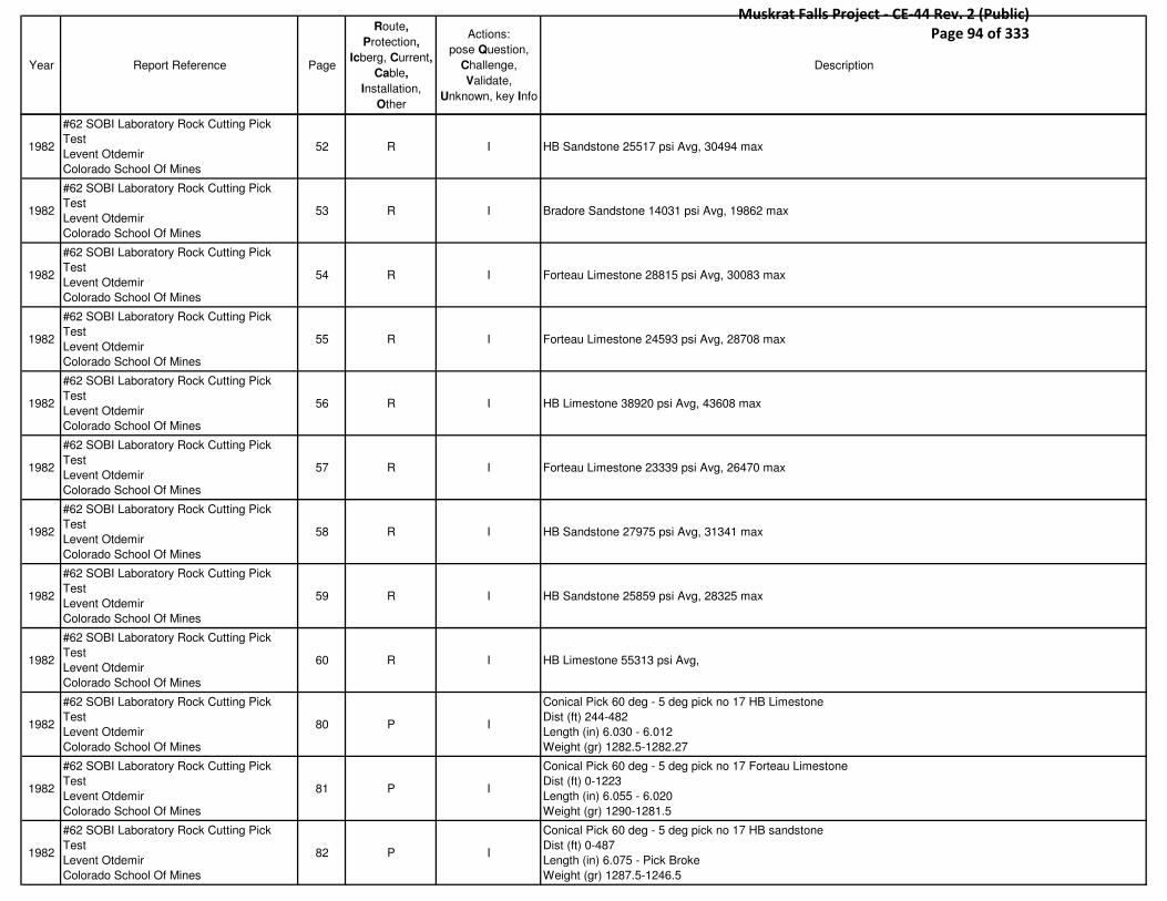
Year Report Reference Page
Route,
Protection,
Icberg, Current,
Cable,
Installation,
Other
Actions:
pose Question,
Challenge,
Validate,
Unknown, key Info
Description
1982
#62 SOBI Laboratory Rock Cutting Pick
Test
Levent Otdemir
Colorado School Of Mines
52 R I HB Sandstone 25517 psi Avg, 30494 max
1982
#62 SOBI Laboratory Rock Cutting Pick
Test
Levent Otdemir
Colorado School Of Mines
53 R I Bradore Sandstone 14031 psi Avg, 19862 max
1982
#62 SOBI Laboratory Rock Cutting Pick
Test
Levent Otdemir
Colorado School Of Mines
54 R I Forteau Limestone 28815 psi Avg, 30083 max
1982
#62 SOBI Laboratory Rock Cutting Pick
Test
Levent Otdemir
Colorado School Of Mines
55 R I Forteau Limestone 24593 psi Avg, 28708 max
1982
#62 SOBI Laboratory Rock Cutting Pick
Test
Levent Otdemir
Colorado School Of Mines
56 R I HB Limestone 38920 psi Avg, 43608 max
1982
#62 SOBI Laboratory Rock Cutting Pick
Test
Levent Otdemir
Colorado School Of Mines
57 R I Forteau Limestone 23339 psi Avg, 26470 max
1982
#62 SOBI Laboratory Rock Cutting Pick
Test
Levent Otdemir
Colorado School Of Mines
58 R I HB Sandstone 27975 psi Avg, 31341 max
1982
#62 SOBI Laboratory Rock Cutting Pick
Test
Levent Otdemir
Colorado School Of Mines
59 R I HB Sandstone 25859 psi Avg, 28325 max
1982
#62 SOBI Laboratory Rock Cutting Pick
Test
Levent Otdemir
Colorado School Of Mines
60 R I HB Limestone 55313 psi Avg,
1982
#62 SOBI Laboratory Rock Cutting Pick
Test
Levent Otdemir
Colorado School Of Mines
80 P I
Conical Pick 60 deg - 5 deg pick no 17 HB Limestone
Dist (ft) 244-482
Length (in) 6.030 - 6.012
Weight (gr) 1282.5-1282.27
1982
#62 SOBI Laboratory Rock Cutting Pick
Test
Levent Otdemir
Colorado School Of Mines
81 P I
Conical Pick 60 deg - 5 deg pick no 17 Forteau Limestone
Dist (ft) 0-1223
Length (in) 6.055 - 6.020
Weight (gr) 1290-1281.5
1982
#62 SOBI Laboratory Rock Cutting Pick
Test
Levent Otdemir
Colorado School Of Mines
82 P I
Conical Pick 60 deg - 5 deg pick no 17 HB sandstone
Dist (ft) 0-487
Length (in) 6.075 - Pick Broke
Weight (gr) 1287.5-1246.5
Muskrat Falls Project - CE-44 Rev. 2 (Public) Page 94 of 333

Year Report Reference Page
Route,
Protection,
Icberg, Current,
Cable,
Installation,
Other
Actions:
pose Question,
Challenge,
Validate,
Unknown, key Info
Description
1982
#62 SOBI Laboratory Rock Cutting Pick
Test
Levent Otdemir
Colorado School Of Mines
83 P I
Conical Pick 60 deg - 5 deg pick no 17 HB sandstone
Dist (ft) 0-260
Length (in) 6.075 - 5.950
Weight (gr) 1284.75-1268.80
1982
#62 SOBI Laboratory Rock Cutting Pick
Test
Levent Otdemir
Colorado School Of Mines
128 P IConical bit force required 6900 lbs at a cut spacing 1.25", penetration 0.5"
1982
#62 SOBI Laboratory Rock Cutting Pick
Test
Levent Otdemir
Colorado School Of Mines
129 P I
Disc Cutter requires 50% more thrust
- It becomes evident that from a cutter drum torque point of view, a machine with disc roller type cutters would
have lower torque and power requirements
1982
#62 SOBI Laboratory Rock Cutting Pick
Test
Levent Otdemir
Colorado School Of Mines
138 P I Plow bit by (Sandvik) Failed Not Feasible!
1982
#62 SOBI Laboratory Rock Cutting Pick
Test
Levent Otdemir
Colorado School Of Mines
138 P I Conical Bit (Bortunco) can do the job, cut with minimal wear
1982
#62 SOBI Laboratory Rock Cutting Pick
Test
Levent Otdemir
Colorado School Of Mines
140 P I Disc Cutting showed it can cut limestone (Superior wear characteristics)
1982
#63 Proposed SOBI Submarine Cable
Installation Oceanographic Aspects
R.G.Ingram
7 C V
BIO 1980 current
15m 2-4 knots
50m 2-3 Knots
Current Observed (Max)
North Side
15m 5.2 knots
50m 3.8 knots
South Side
15m 3.4 knots
50m 2.6 knots
*Combining the maximum observed residual flow 1.6m/s and the largest tidal current 2.0 m/s would produce the
7.2 knot current at 15m and a max at 50 m of 5 knots
1982
#63 Proposed SOBI Submarine Cable
Installation Oceanographic Aspects
R.G.Ingram
17 C USNC- No instrument placed at the narrowest section of the strait, depth in the section is also greater than that of
the narrowest section therefore current for this area are likely lower then maximum.
1982
#63 Proposed SOBI Submarine Cable
Installation Oceanographic Aspects
R.G.Ingram
28 I IMax Wave 1981
Sept and Oct 5m
1982
#63 Proposed SOBI Submarine Cable
Installation Oceanographic Aspects
R.G.Ingram
39 Ic V Scouring can occur up to depths of 140m anywhere in SOBI
Muskrat Falls Project - CE-44 Rev. 2 (Public) Page 95 of 333

Year Report Reference Page
Route,
Protection,
Icberg, Current,
Cable,
Installation,
Other
Actions:
pose Question,
Challenge,
Validate,
Unknown, key Info
Description
1982
#63 Proposed SOBI Submarine Cable
Installation Oceanographic Aspects
R.G.Ingram
39 P C Cables to be placed in trenches 1.5m deep
1982
#64 Report On Seabottom Overburden
Removal For SOBI
Santa Fe Technical Services Co.
3-1 P I
Due to excessively high drawdown forces 1800 tons or more it is not feasible to clear the overburden by plowing
along recommended route.
-Plowing is abandoned
1982
#64 Report On Seabottom Overburden
Removal For SOBI
Santa Fe Technical Services Co.
3-1 P IHydraulic Jetting or/and pumping (educator pumps) better choice
1982
#64 Report On Seabottom Overburden
Removal For SOBI
Santa Fe Technical Services Co.
3-1 C I Nordco 1979 (bottom current 1 Knot)
1982
#64 Report On Seabottom Overburden
Removal For SOBI
Santa Fe Technical Services Co.
3-2 P IRecommended 7m wide, 4 m deep trench
-Pump 95% of overburden + Plow 5 %
1982
#64 Report On Seabottom Overburden
Removal For SOBI
Santa Fe Technical Services Co.
4-8 P I
Pumped & Plowed
-Pumping 95% of overburden (Up to 3" size as specified)
-Removing gravel and rocks by means of plowing
1982
#64 Report On Seabottom Overburden
Removal For SOBI
Santa Fe Technical Services Co.
4-15 P I
Hydrautic Dredging Analysis
-Pumping of submerged materials (Fine particles -6" rock in a water slurry)
-Slurry flow is 30000 gpm 10% overburden
1982
#64 Report On Seabottom Overburden
Removal For SOBI
Santa Fe Technical Services Co.
4-16 P I
From program and assumptions
-2.5m deep, 7m wide
-Volume/Unit Length 30m^3/m
-Rate= 6.25m^3/min
1982
#64 Report On Seabottom Overburden
Removal For SOBI
Santa Fe Technical Services Co.
4-23 P I
Plowing Analysis
-R.J. Brown (Cohesive Soil)
-Plow weight 100ton, 650 tons to excavate the ditch
S.Hata Kyoto University
Ditch is v-shaped with small width @ bottom: result 1950 tons
1982
#64 Report On Seabottom Overburden
Removal For SOBI
Santa Fe Technical Services Co.
4-24 P IHydraulic Jetting Analysis
Nozzle 1/8" to 7/16" 1000-2500 psig (various set ups)
1982
#64 Report On Seabottom Overburden
Removal For SOBI
Santa Fe Technical Services Co.
4-25 P I
Sled Configuration
7m long, 4m deep
One pass sled is recommended because:
-Position control needed for multiple passes is difficult if not impossible in the environment regardless of number of
passes, the spoil piles must be deposited the same distance from the ditch centerline and finally a one pass
ditcher should be faster therefore less expensive
-160 ton can only be met by towing
-Unmanned sled is recommended
-2000gpm pumps, jet nozzles for creating ditch
-Not self Propelled
Muskrat Falls Project - CE-44 Rev. 2 (Public) Page 96 of 333

Year Report Reference Page
Route,
Protection,
Icberg, Current,
Cable,
Installation,
Other
Actions:
pose Question,
Challenge,
Validate,
Unknown, key Info
Description
1982
#64 Report On Seabottom Overburden
Removal For SOBI
Santa Fe Technical Services Co.
- P I
Recommended Ditcher
-Water jets to break up overburden creating (slurry)
-Water educators to transport the spoil
-Trailing Plow to Punch aside larger rocks
1982
#64 Report On Seabottom Overburden
Removal For SOBI
Santa Fe Technical Services Co.
- P I
Barge Mooring Analysis
Capable Requirements
1. wind & current (47000 lb) (3 knots) = 211000 (106 tons)
2. Sled Towing force (300000lb) (150tons)
1982#65 Rock and Soil Testing SOBI
Golder Associates - R I
Sample Comp Strength (Mpa)
17 130
21 138
28 145
30 215
34 238
203 176
206A 248
39 244
1982
#66 SOBI HVdc Transmission Submarine
Cable Scheme
SNC-Lavalin
1-7 I C Waves up to 3m with swell currents
1982
#66 SOBI HVdc Transmission Submarine
Cable Scheme
SNC-Lavalin
2-17 R C
HB Dolomitic Limestone 394MPa
HB Orthoquartzite Sandstone 238 Mpa
Forteau Limestone 257 Mpa
Bradore Sandstone 150 Mpa
1982
#66 SOBI HVdc Transmission Submarine
Cable Scheme
SNC-Lavalin
2-18 R C One extreme sample 480 Mpa
1982
#66 SOBI HVdc Transmission Submarine
Cable Scheme
SNC-Lavalin
3-2 I I Table of wind speeds may, June, July, aug, sept, oct for 1971,81,
1982
#66 SOBI HVdc Transmission Submarine
Cable Scheme
SNC-Lavalin
- C V Current Data again max was BIO 4.9 knots recorded BIO
1982
#66 SOBI HVdc Transmission Submarine
Cable Scheme
SNC-Lavalin
Table
4.4C V Gumbel analysis extreme current predictions and Weibull Model as will max prediction 4.6 Knots 5yr return period.
1982
#66 SOBI HVdc Transmission Submarine
Cable Scheme
SNC-Lavalin
5-5 Ic VMax Draft increase of iceberg is 13.3m (70m draft) of tabular/drydock
*Same iceberg information as in report #68
1982
#66 SOBI HVdc Transmission Submarine
Cable Scheme
SNC-Lavalin
Section
A- - Section A uses mostly same information as report 68
Muskrat Falls Project - CE-44 Rev. 2 (Public) Page 97 of 333

Year Report Reference Page
Route,
Protection,
Icberg, Current,
Cable,
Installation,
Other
Actions:
pose Question,
Challenge,
Validate,
Unknown, key Info
Description
1982
#66 SOBI HVdc Transmission Submarine
Cable Scheme
SNC-Lavalin
7-2 P I
Dredging/ Jetting Companies That Need More Development But May be Feasible
1. Volker Stevin-Aveco
2. Zanen Verstoep
3. Land and Marine
4. Sante Fe
5. Verreault Navigation
6. Brown and Root
*Some information about cutters and trenches but no proven technologies
1982
#67 Analysis Of The Available Information
On The Overburden SOBI Crossing
Jean-Y Changnon
26 C V Max measured bottom current 2.75 knots
1982
#67 Analysis Of The Available Information
On The Overburden SOBI Crossing
Jean-Y Changnon
27 C V Nordco Says 4 knots max measured 3.15 knots
1982
#67 Analysis Of The Available Information
On The Overburden SOBI Crossing
Jean-Y Changnon
27 C V RG Ingram 7 knots upper 3.8 bottom
1982
#67 Analysis Of The Available Information
On The Overburden SOBI Crossing
Jean-Y Changnon
- R I
*This report contains good overburden but is superseded
Overburden 0-4m Avg 1.5m
Lab side pockets up to 9m
1982
#68 SOBI Crossing HVdc Transmission
Submarine Power Cable Scheme
SNC-Lavalin
Vol I Engineering Report-Cost Estimate and
Project Schedule
Part A (Not Included)
Part B Summary description of 1981 results
and related engineering studies
9-6 R I
Rock Type Comp Strength Silica Content(%)
HB Dolomitic 289 394 5 18.7
HB Orthoquartzite 144 238 77 95
Forteau Limestone 167 257 5 6.4
Bradore Sandstone 84 150 77 91.5
1982
#68 SOBI Crossing HVdc Transmission
Submarine Power Cable Scheme
SNC-Lavalin
Vol I Engineering Report-Cost Estimate and
Project Schedule
Part A (Not Included)
Part B Summary description of 1981 results
and related engineering studies
- O I Good meteorological Data However it is the same data from report #69 in less detail
Muskrat Falls Project - CE-44 Rev. 2 (Public) Page 98 of 333

Year Report Reference Page
Route,
Protection,
Icberg, Current,
Cable,
Installation,
Other
Actions:
pose Question,
Challenge,
Validate,
Unknown, key Info
Description
1982
#68 SOBI Crossing HVdc Transmission
Submarine Power Cable Scheme
SNC-Lavalin
Vol I Engineering Report-Cost Estimate and
Project Schedule
Part A (Not Included)
Part B Summary description of 1981 results
and related engineering studies
12-13 Ic I
Type Draft Rollover inc Instantaneous Inc Tilting Inc
Tabular/Drydock 40 3 10 -
50 1.3 11.3 -
60 - 12.6 -
70 - 13.3 -
Wedge/Pyramid 40 - - 7.2
50 - - 8
60 - - 8.7
70 - - 9.1
- means it cant happen
1982
#68 SOBI Crossing HVdc Transmission
Submarine Power Cable Scheme
SNC-Lavalin
Vol I Engineering Report-Cost Estimate and
Project Schedule
Part A (Not Included)
Part B Summary description of 1981 results
and related engineering studies
12-13 Ic I *no icebergs analyzed in this study can increase draft more then 3m
1982
#68 SOBI Crossing HVdc Transmission
Submarine Power Cable Scheme
SNC-Lavalin
Vol I Engineering Report-Cost Estimate and
Project Schedule
Part A (Not Included)
Part B Summary description of 1981 results
and related engineering studies
12-19 Ic V
Draft % Icebergs With Sufficient Energy To Cross Sill
75-80 50
80-85 20
85-90 5
*Rollover due to calving is not considered
1982
#68 SOBI Crossing HVdc Transmission
Submarine Power Cable Scheme
SNC-Lavalin
Vol I Engineering Report-Cost Estimate and
Project Schedule
Part A (Not Included)
Part B Summary description of 1981 results
and related engineering studies
12-19 Ic V
Pcc=Px X Pr X Pp
Probable Iceberg Distribution at The Cable Crossing
Px- Probability of crossing sill
Pr- Probability of iceberg reaching the crossing
Pp- Probable population distribution
Sp=Pcc X Ps
*From static stability Kollemeyers report is fine but fails to take into account the mechanism that would cause
iceberg rollover, & the amount of energy necessary for rollover
Muskrat Falls Project - CE-44 Rev. 2 (Public) Page 99 of 333
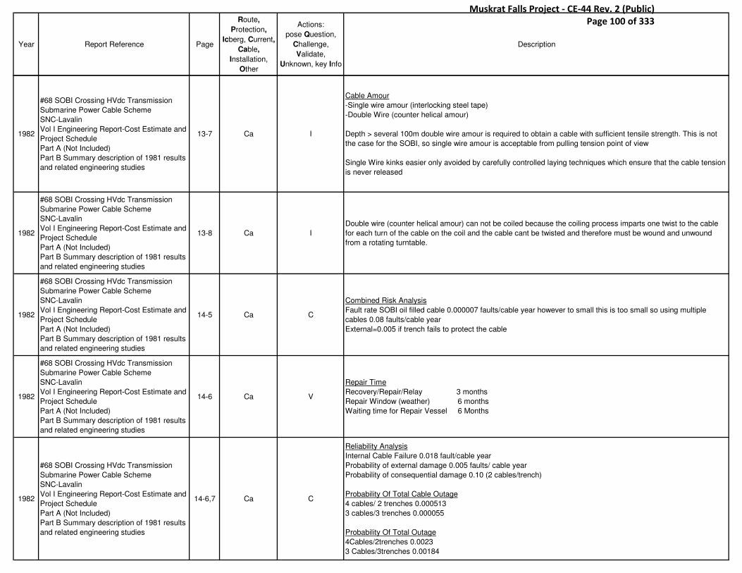
Year Report Reference Page
Route,
Protection,
Icberg, Current,
Cable,
Installation,
Other
Actions:
pose Question,
Challenge,
Validate,
Unknown, key Info
Description
1982
#68 SOBI Crossing HVdc Transmission
Submarine Power Cable Scheme
SNC-Lavalin
Vol I Engineering Report-Cost Estimate and
Project Schedule
Part A (Not Included)
Part B Summary description of 1981 results
and related engineering studies
13-7 Ca I
Cable Amour
-Single wire amour (interlocking steel tape)
-Double Wire (counter helical amour)
Depth > several 100m double wire amour is required to obtain a cable with sufficient tensile strength. This is not
the case for the SOBI, so single wire amour is acceptable from pulling tension point of view
Single Wire kinks easier only avoided by carefully controlled laying techniques which ensure that the cable tension
is never released
1982
#68 SOBI Crossing HVdc Transmission
Submarine Power Cable Scheme
SNC-Lavalin
Vol I Engineering Report-Cost Estimate and
Project Schedule
Part A (Not Included)
Part B Summary description of 1981 results
and related engineering studies
13-8 Ca I
Double wire (counter helical amour) can not be coiled because the coiling process imparts one twist to the cable
for each turn of the cable on the coil and the cable cant be twisted and therefore must be wound and unwound
from a rotating turntable.
1982
#68 SOBI Crossing HVdc Transmission
Submarine Power Cable Scheme
SNC-Lavalin
Vol I Engineering Report-Cost Estimate and
Project Schedule
Part A (Not Included)
Part B Summary description of 1981 results
and related engineering studies
14-5 Ca C
Combined Risk Analysis
Fault rate SOBI oil filled cable 0.000007 faults/cable year however to small this is too small so using multiple
cables 0.08 faults/cable year
External=0.005 if trench fails to protect the cable
1982
#68 SOBI Crossing HVdc Transmission
Submarine Power Cable Scheme
SNC-Lavalin
Vol I Engineering Report-Cost Estimate and
Project Schedule
Part A (Not Included)
Part B Summary description of 1981 results
and related engineering studies
14-6 Ca V
Repair Time
Recovery/Repair/Relay 3 months
Repair Window (weather) 6 months
Waiting time for Repair Vessel 6 Months
1982
#68 SOBI Crossing HVdc Transmission
Submarine Power Cable Scheme
SNC-Lavalin
Vol I Engineering Report-Cost Estimate and
Project Schedule
Part A (Not Included)
Part B Summary description of 1981 results
and related engineering studies
14-6,7 Ca C
Reliability Analysis
Internal Cable Failure 0.018 fault/cable year
Probability of external damage 0.005 faults/ cable year
Probability of consequential damage 0.10 (2 cables/trench)
Probability Of Total Cable Outage
4 cables/ 2 trenches 0.000513
3 cables/3 trenches 0.000055
Probability Of Total Outage
4Cables/2trenches 0.0023
3 Cables/3trenches 0.00184
Muskrat Falls Project - CE-44 Rev. 2 (Public) Page 100 of 333
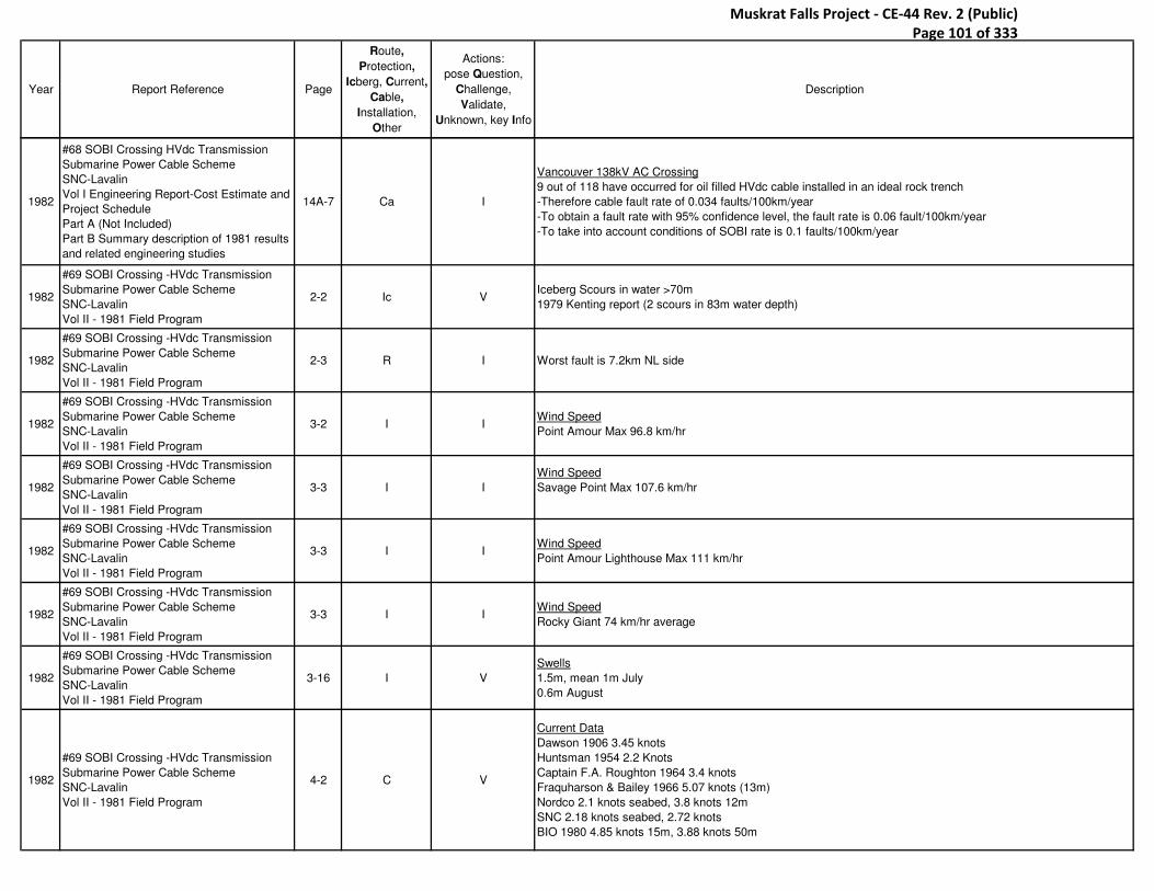
Year Report Reference Page
Route,
Protection,
Icberg, Current,
Cable,
Installation,
Other
Actions:
pose Question,
Challenge,
Validate,
Unknown, key Info
Description
1982
#68 SOBI Crossing HVdc Transmission
Submarine Power Cable Scheme
SNC-Lavalin
Vol I Engineering Report-Cost Estimate and
Project Schedule
Part A (Not Included)
Part B Summary description of 1981 results
and related engineering studies
14A-7 Ca I
Vancouver 138kV AC Crossing
9 out of 118 have occurred for oil filled HVdc cable installed in an ideal rock trench
-Therefore cable fault rate of 0.034 faults/100km/year
-To obtain a fault rate with 95% confidence level, the fault rate is 0.06 fault/100km/year
-To take into account conditions of SOBI rate is 0.1 faults/100km/year
1982
#69 SOBI Crossing -HVdc Transmission
Submarine Power Cable Scheme
SNC-Lavalin
Vol II - 1981 Field Program
2-2 Ic VIceberg Scours in water >70m
1979 Kenting report (2 scours in 83m water depth)
1982
#69 SOBI Crossing -HVdc Transmission
Submarine Power Cable Scheme
SNC-Lavalin
Vol II - 1981 Field Program
2-3 R I Worst fault is 7.2km NL side
1982
#69 SOBI Crossing -HVdc Transmission
Submarine Power Cable Scheme
SNC-Lavalin
Vol II - 1981 Field Program
3-2 I IWind Speed
Point Amour Max 96.8 km/hr
1982
#69 SOBI Crossing -HVdc Transmission
Submarine Power Cable Scheme
SNC-Lavalin
Vol II - 1981 Field Program
3-3 I I
Wind Speed
Savage Point Max 107.6 km/hr
1982
#69 SOBI Crossing -HVdc Transmission
Submarine Power Cable Scheme
SNC-Lavalin
Vol II - 1981 Field Program
3-3 I IWind Speed
Point Amour Lighthouse Max 111 km/hr
1982
#69 SOBI Crossing -HVdc Transmission
Submarine Power Cable Scheme
SNC-Lavalin
Vol II - 1981 Field Program
3-3 I IWind Speed
Rocky Giant 74 km/hr average
1982
#69 SOBI Crossing -HVdc Transmission
Submarine Power Cable Scheme
SNC-Lavalin
Vol II - 1981 Field Program
3-16 I V
Swells
1.5m, mean 1m July
0.6m August
1982
#69 SOBI Crossing -HVdc Transmission
Submarine Power Cable Scheme
SNC-Lavalin
Vol II - 1981 Field Program
4-2 C V
Current Data
Dawson 1906 3.45 knots
Huntsman 1954 2.2 Knots
Captain F.A. Roughton 1964 3.4 knots
Fraquharson & Bailey 1966 5.07 knots (13m)
Nordco 2.1 knots seabed, 3.8 knots 12m
SNC 2.18 knots seabed, 2.72 knots
BIO 1980 4.85 knots 15m, 3.88 knots 50m
Muskrat Falls Project - CE-44 Rev. 2 (Public) Page 101 of 333
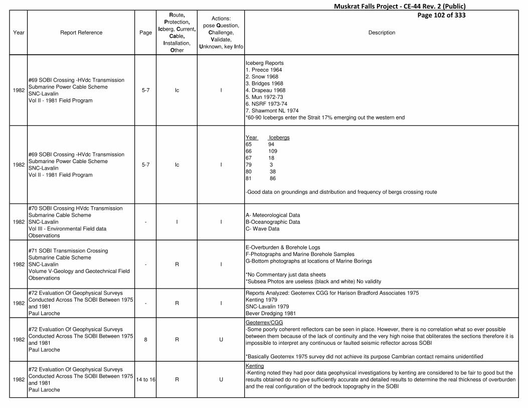
Year Report Reference Page
Route,
Protection,
Icberg, Current,
Cable,
Installation,
Other
Actions:
pose Question,
Challenge,
Validate,
Unknown, key Info
Description
1982
#69 SOBI Crossing -HVdc Transmission
Submarine Power Cable Scheme
SNC-Lavalin
Vol II - 1981 Field Program
5-7 Ic I
Iceberg Reports
1. Preece 1964
2. Snow 1968
3. Bridges 1968
4. Drapeau 1968
5. Mun 1972-73
6. NSRF 1973-74
7. Shawmont NL 1974
*60-90 Icebergs enter the Strait 17% emerging out the western end
1982
#69 SOBI Crossing -HVdc Transmission
Submarine Power Cable Scheme
SNC-Lavalin
Vol II - 1981 Field Program
5-7 Ic I
Year Icebergs
65 94
66 109
67 18
79 3
80 38
81 86
-Good data on groundings and distribution and frequency of bergs crossing route
1982
#70 SOBI Crossing HVdc Transmission
Submarine Cable Scheme
SNC-Lavalin
Vol III - Environmental Field data
Observations
- I I
A- Meteorological Data
B-Oceanographic Data
C- Wave Data
1982
#71 SOBI Transmission Crossing
Submarine Cable Scheme
SNC-Lavalin
Volume V-Geology and Geotechnical Field
Observations
- R I
E-Overburden & Borehole Logs
F-Photographs and Marine Borehole Samples
G-Bottom photographs at locations of Marine Borings
*No Commentary just data sheets
*Subsea Photos are useless (black and white) No validity
1982
#72 Evaluation Of Geophysical Surveys
Conducted Across The SOBI Between 1975
and 1981
Paul Laroche
- R I
Reports Analyzed: Geoterrex CGG for Harison Bradford Associates 1975
Kenting 1979
SNC-Lavalin 1979
Bever Dredging 1981
1982
#72 Evaluation Of Geophysical Surveys
Conducted Across The SOBI Between 1975
and 1981
Paul Laroche
8 R U
Geoterrex/CGG
-Some poorly coherent reflectors can be seen in place. However, there is no correlation what so ever possible
between them because of the lack of continuity and the very high noise that obliterates the sections therefore it is
impossible to interpret any continuous or faulted seismic reflector across SOBI
*Basically Geoterrex 1975 survey did not achieve its purpose Cambrian contact remains unidentified
1982
#72 Evaluation Of Geophysical Surveys
Conducted Across The SOBI Between 1975
and 1981
Paul Laroche
14 to 16 R U
Kenting
-Kenting noted they had poor data geophysical investigations by kenting are considered to be fair to good but the
results obtained do no give sufficiently accurate and detailed results to determine the real thickness of overburden
and the real configuration of the bedrock topography in the SOBI
Muskrat Falls Project - CE-44 Rev. 2 (Public) Page 102 of 333
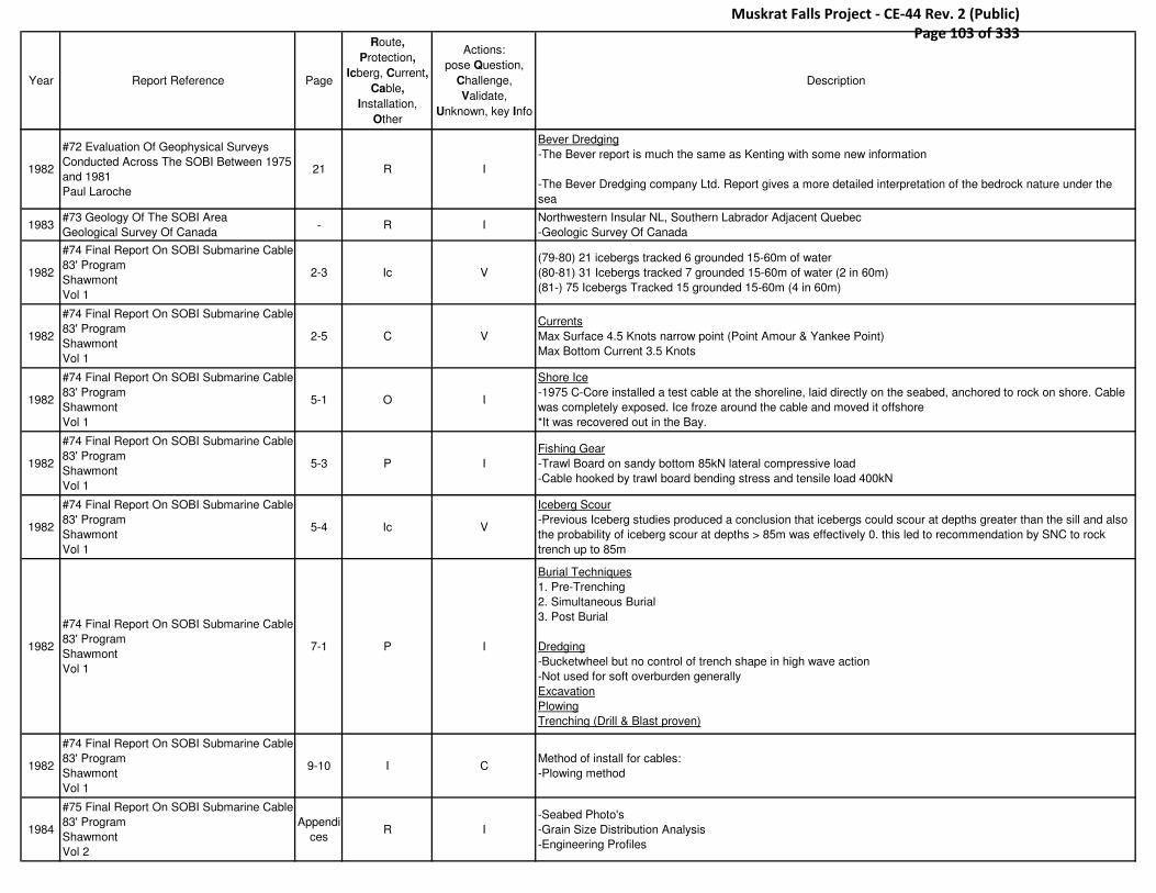
Year Report Reference Page
Route,
Protection,
Icberg, Current,
Cable,
Installation,
Other
Actions:
pose Question,
Challenge,
Validate,
Unknown, key Info
Description
1982
#72 Evaluation Of Geophysical Surveys
Conducted Across The SOBI Between 1975
and 1981
Paul Laroche
21 R I
Bever Dredging
-The Bever report is much the same as Kenting with some new information
-The Bever Dredging company Ltd. Report gives a more detailed interpretation of the bedrock nature under the
sea
1983#73 Geology Of The SOBI Area
Geological Survey Of Canada- R I
Northwestern Insular NL, Southern Labrador Adjacent Quebec
-Geologic Survey Of Canada
1982
#74 Final Report On SOBI Submarine Cable
83' Program
Shawmont
Vol 1
2-3 Ic V
(79-80) 21 icebergs tracked 6 grounded 15-60m of water
(80-81) 31 Icebergs tracked 7 grounded 15-60m of water (2 in 60m)
(81-) 75 Icebergs Tracked 15 grounded 15-60m (4 in 60m)
1982
#74 Final Report On SOBI Submarine Cable
83' Program
Shawmont
Vol 1
2-5 C V
Currents
Max Surface 4.5 Knots narrow point (Point Amour & Yankee Point)
Max Bottom Current 3.5 Knots
1982
#74 Final Report On SOBI Submarine Cable
83' Program
Shawmont
Vol 1
5-1 O I
Shore Ice
-1975 C-Core installed a test cable at the shoreline, laid directly on the seabed, anchored to rock on shore. Cable
was completely exposed. Ice froze around the cable and moved it offshore
*It was recovered out in the Bay.
1982
#74 Final Report On SOBI Submarine Cable
83' Program
Shawmont
Vol 1
5-3 P I
Fishing Gear
-Trawl Board on sandy bottom 85kN lateral compressive load
-Cable hooked by trawl board bending stress and tensile load 400kN
1982
#74 Final Report On SOBI Submarine Cable
83' Program
Shawmont
Vol 1
5-4 Ic V
Iceberg Scour
-Previous Iceberg studies produced a conclusion that icebergs could scour at depths greater than the sill and also
the probability of iceberg scour at depths > 85m was effectively 0. this led to recommendation by SNC to rock
trench up to 85m
1982
#74 Final Report On SOBI Submarine Cable
83' Program
Shawmont
Vol 1
7-1 P I
Burial Techniques
1. Pre-Trenching
2. Simultaneous Burial
3. Post Burial
Dredging
-Bucketwheel but no control of trench shape in high wave action
-Not used for soft overburden generally
Excavation
Plowing
Trenching (Drill & Blast proven)
1982
#74 Final Report On SOBI Submarine Cable
83' Program
Shawmont
Vol 1
9-10 I CMethod of install for cables:
-Plowing method
1984
#75 Final Report On SOBI Submarine Cable
83' Program
Shawmont
Vol 2
Appendi
cesR I
-Seabed Photo's
-Grain Size Distribution Analysis
-Engineering Profiles
Muskrat Falls Project - CE-44 Rev. 2 (Public) Page 103 of 333
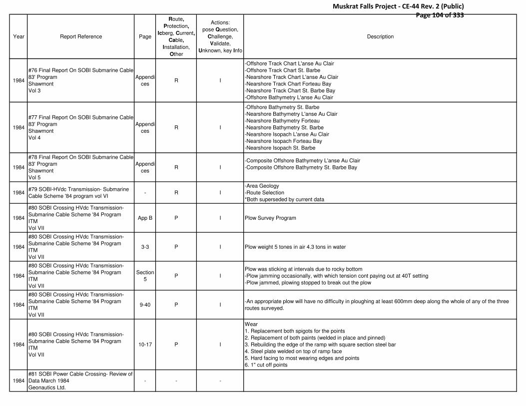
Year Report Reference Page
Route,
Protection,
Icberg, Current,
Cable,
Installation,
Other
Actions:
pose Question,
Challenge,
Validate,
Unknown, key Info
Description
1984
#76 Final Report On SOBI Submarine Cable
83' Program
Shawmont
Vol 3
Appendi
cesR I
-Offshore Track Chart L'anse Au Clair
-Offshore Track Chart St. Barbe
-Nearshore Track Chart L'anse Au Clair
-Nearshore Track Chart Forteau Bay
-Nearshore Track Chart St. Barbe Bay
-Offshore Bathymetry L'anse Au Clair
1984
#77 Final Report On SOBI Submarine Cable
83' Program
Shawmont
Vol 4
Appendi
cesR I
-Offshore Bathymetry St. Barbe
-Nearshore Bathymetry L'anse Au Clair
-Nearshore Bathymetry Forteau
-Nearshore Bathymetry St. Barbe
-Nearshore Isopach L'anse Au Clair
-Nearshore Isopach Forteau Bay
-Nearshore Isopach St. Barbe
1984
#78 Final Report On SOBI Submarine Cable
83' Program
Shawmont
Vol 5
Appendi
cesR I
-Composite Offshore Bathymetry L'anse Au Clair
-Composite Offshore Bathymetry St. Barbe Bay
1984#79 SOBI-HVdc Transmission- Submarine
Cable Scheme '84 program vol VI- R I
-Area Geology
-Route Selection
*Both superseded by current data
1984
#80 SOBI Crossing HVdc Transmission-
Submarine Cable Scheme '84 Program
ITM
Vol VII
App B P I Plow Survey Program
1984
#80 SOBI Crossing HVdc Transmission-
Submarine Cable Scheme '84 Program
ITM
Vol VII
3-3 P I Plow weight 5 tones in air 4.3 tons in water
1984
#80 SOBI Crossing HVdc Transmission-
Submarine Cable Scheme '84 Program
ITM
Vol VII
Section
5P I
Plow was sticking at intervals due to rocky bottom
-Plow jamming occasionally, with which tension cont paying out at 40T setting
-Plow jammed, plowing stopped to break out the plow
1984
#80 SOBI Crossing HVdc Transmission-
Submarine Cable Scheme '84 Program
ITM
Vol VII
9-40 P I-An appropriate plow will have no difficulty in ploughing at least 600mm deep along the whole of any of the three
routes surveyed.
1984
#80 SOBI Crossing HVdc Transmission-
Submarine Cable Scheme '84 Program
ITM
Vol VII
10-17 P I
Wear
1. Replacement both spigots for the points
2. Replacement of both paints (welded in place and pinned)
3. Rebuilding the edge of the ramp with square section steel bar
4. Steel plate welded on top of ramp face
5. Hard facing to most wearing edges and points
6. 1" cut off points
1984
#81 SOBI Power Cable Crossing- Review of
Data March 1984
Geonautics Ltd.
- - -
Muskrat Falls Project - CE-44 Rev. 2 (Public) Page 104 of 333

Year Report Reference Page
Route,
Protection,
Icberg, Current,
Cable,
Installation,
Other
Actions:
pose Question,
Challenge,
Validate,
Unknown, key Info
Description
1984
#82 SOBI HVdc Transmission Submarine
Cable Scheme '84 Program
Marenco Engineering Ltd.
Vol VIII
- I I
Appendices
C,D,E Landing Site Investigations
F Horizontal Positioning
G Fishing Activities Study
1984
#82 SOBI HVdc Transmission Submarine
Cable Scheme '84 Program
Marenco Engineering Ltd.
Vol VIII
7 P U
App c
-L'Anse-Au-Clair will make excellent cable landing site 2-3m burial depth 20m
*Recommend -Short length of trench be excavated near shore during the design stage to ensure the excavation
will remain open long enough to allow for the install
1984
#82 SOBI HVdc Transmission Submarine
Cable Scheme '84 Program
Marenco Engineering Ltd.
Vol VIII
2 R I
App d
Test on cemented sand 24-35 Mpa
3.4-31Mpa
1984
#82 SOBI HVdc Transmission Submarine
Cable Scheme '84 Program
Marenco Engineering Ltd.
Vol VIII
15,16 P V
App g
Fishing Activities
-Approx 95% of all damage caused to communication cables is attributed to fishing activities
-Bottom Trawling has posed the main threat
-December 1984 meeting of the international cable committee reported 100% success rate for all buried cables in
terms of totally eliminating damage caused by fishing activities
-However, sand waves have been a problem in some areas and have caused sections of buried cables to become
exposed
1984
#82 SOBI HVdc Transmission Submarine
Cable Scheme '84 Program
Marenco Engineering Ltd.
Vol VIII
16 P I
Issue
Cable Denmark-Sweden equipped with heavy armoring to withstand impacts of trawl gear 1968-73 considerable
damage was caused to the cable by intensive trawling activities
1984
#82 SOBI HVdc Transmission Submarine
Cable Scheme '84 Program
Marenco Engineering Ltd.
Vol VIII
17 P I
Issue
-PEI-NB 100MW submarine electric cable across Northumberland Strait. -This connection became known as the
longest buried oil-filled cable 21.5km
- 2 km could not be buried due to rock conditions (concrete mattresses)
-Recent examination of the cable showed interference from fishing gear
-In some sandy areas the cable has become exposed due to tide and current conditions
1984
#82 SOBI HVdc Transmission Submarine
Cable Scheme '84 Program
Marenco Engineering Ltd.
Vol VIII
23 P V Impact from fishing gear 15-35 milliseconds
1984
#82 SOBI HVdc Transmission Submarine
Cable Scheme '84 Program
Marenco Engineering Ltd.
Vol VIII
28 P V Fishing Gear Penetrate seabed 5-8 cm, 14cm in sand
1984
#83 1984 Subsea Plow Survey Program -
Preliminary Results
HW Green
2 P IITM Test Plow
-5 ton, 265cm long, 84cm high, 19cm wide
1984
#83 1984 Subsea Plow Survey Program -
Preliminary Results
HW Green
3 P I Test plow speed Avg 1km/hr, max speed 2.7km/hr
Muskrat Falls Project - CE-44 Rev. 2 (Public) Page 105 of 333

Year Report Reference Page
Route,
Protection,
Icberg, Current,
Cable,
Installation,
Other
Actions:
pose Question,
Challenge,
Validate,
Unknown, key Info
Description
1984
#83 1984 Subsea Plow Survey Program -
Preliminary Results
HW Green
3 R I In Areas of bedrock exposure on all 3 routes plow progress was temporarily halted when plow became stuck
1984
#83 1984 Subsea Plow Survey Program -
Preliminary Results
HW Green
5 P I -All three routes are plowable
1984
#83 1984 Subsea Plow Survey Program -
Preliminary Results
HW Green
section
4 P C
Shawmont Portion
Problems:
-Plow to hang up and then shoot ahead rapidly as the tension in the tow wire increased to a sufficient level for it to
break free
-Tendency for the plow to ride in and out of the material very irregularly as it passes over boulders or ridges of
rock. this has implications when laying the cable since the bending radius will cause it to ride the ridges and span
the depressions thereby minimizing penetration and possibly causing point loads on the cable amour
1987
#84A Final Report SOBI Iceberg Tracking
Program April 1987-Oct 1987
Fenco NFLD.
3-1 Ic I34 bergs
23 bergs made it inside area of interest
1987
#84A Final Report SOBI Iceberg Tracking
Program April 1987-Oct 1987
Fenco NFLD.
3-3 Ic VTable
Estimated Iceberg Parameter Information (number, type, draft grounding)
1987
#84A Final Report SOBI Iceberg Tracking
Program April 1987-Oct 1987
Fenco NFLD.
3-11 Ic VBerg 15
5.5 nautical miles off Point Amour 70-80m water 3 hours stationary (Potential grounding)
1987
#84A Final Report SOBI Iceberg Tracking
Program April 1987-Oct 1987
Fenco NFLD.
3-11 Ic V 17 of 34 were noted to have grounded in 24 grounding events
1985#84 SOBI Pisces IV Dives August 1985
Orca Marine Geological Consult- P I
Manned submersible observations of submarine cable test trench in SOBI
*Report to examine trench in a submarine not much portent information
1988
#85 Assessment Of The Practicality Of
Installing A Bedrock Adit, Rock Trench or
Overburden Trench For HVdc Cable
Protection Beneath the SOBI
C. Woodworth Lynas et al (C-Core)
18 P C
Rock Trenching
-The rock cutting characteristics of lithologies beneath the strait have been tested all rock types were found to be
cuttable and preliminary designs for a rock trencher have been achieved
1988
#85 Assessment Of The Practicality Of
Installing A Bedrock Adit, Rock Trench or
Overburden Trench For HVdc Cable
Protection Beneath the SOBI
C. Woodworth Lynas et al (C-Core)
24 Ca I-Northumberland Strait 2x100MW cables installed by (Maritime Electric) 1977 burial depth of 2m
-No scours>0.3m
2004
#88 Fixed Link Between Labrador and
Newfoundland Pre Feasibility Study (Final
Report)
Hatch Mott MacDonald
10 Ic I-By late 1979 a risk associated with iceberg scour problems were conducted and concluded that a cable crossing
(subsea) could be achieved with an appropriate probability of scour
2004
#88 Fixed Link Between Labrador and
Newfoundland Pre Feasibility Study (Final
Report)
Hatch Mott MacDonald
20 C V
Current
15m (7.2 knots)
50m (5 knots)
*No conclusive results
Muskrat Falls Project - CE-44 Rev. 2 (Public) Page 106 of 333
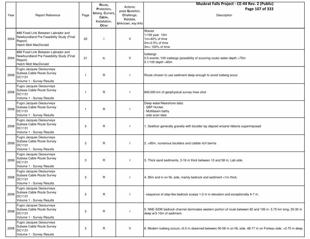
Year Report Reference Page
Route,
Protection,
Icberg, Current,
Cable,
Installation,
Other
Actions:
pose Question,
Challenge,
Validate,
Unknown, key Info
Description
2004
#88 Fixed Link Between Labrador and
Newfoundland Pre Feasibility Study (Final
Report)
Hatch Mott MacDonald
20 I V
Waves
1/100 year 10m
1m>40% of time
2m<2.5% of time
3m< 100% of time
2004
#88 Fixed Link Between Labrador and
Newfoundland Pre Feasibility Study (Final
Report)
Hatch Mott MacDonald
21 Ic V
Icebergs
0.5 events /100 icebergs (possibility of scouring route) water depth >75m
0.1/100 depth >85m
2008
Fugro Jacques Geosurveys
Subsea Cable Route Survey
DC1131
Volume 1 - Survey Results
1 R I Route chosen to use sediment deep enough to avoid iceberg scour
2008
Fugro Jacques Geosurveys
Subsea Cable Route Survey
DC1131
Volume 1 - Survey Results
1 R I 840,000 km of geophysical survey lines shot
2008
Fugro Jacques Geosurveys
Subsea Cable Route Survey
DC1131
Volume 1 - Survey Results
1 R I
Deep water/Nearshore data:
- SBP Huntec
- Multibeam bathy
- side scan data
2008
Fugro Jacques Geosurveys
Subsea Cable Route Survey
DC1131
Volume 1 - Survey Results
3 R I 1. Seafloor generally gravelly with boulder lay deposit w/sand ribbons superimposed
2008
Fugro Jacques Geosurveys
Subsea Cable Route Survey
DC1131
Volume 1 - Survey Results
3 R I 2. >95m, numerous boulders and cobble rich berms
2008
Fugro Jacques Geosurveys
Subsea Cable Route Survey
DC1131
Volume 1 - Survey Results
3 R I 3. Thick sand sediments, 3-16 m thick between 10 and 58 m, Lab side.
2008
Fugro Jacques Geosurveys
Subsea Cable Route Survey
DC1131
Volume 1 - Survey Results
3 R I 4. 95m and in on NL side, mainly bedrock and sediment <1m thick.
2008
Fugro Jacques Geosurveys
Subsea Cable Route Survey
DC1131
Volume 1 - Survey Results
3 R I - sequence of step-like bedrock scarps 1-2 m in elevation and exceptionally 6-7 m.
2008
Fugro Jacques Geosurveys
Subsea Cable Route Survey
DC1131
Volume 1 - Survey Results
3 R I5. NNE-SSW bedrock channel dominates western portion of route between 82 and 106 m. 5.75 km long, 20-30 m
deep w/3-10m of sediment.
2008
Fugro Jacques Geosurveys
Subsea Cable Route Survey
DC1131
Volume 1 - Survey Results
3 R V 6. Modern iceberg scours <0.5 m observed between 50-58 m on NL side, 48-77 m on Forteau side, <0.75 m deep.
Muskrat Falls Project - CE-44 Rev. 2 (Public) Page 107 of 333
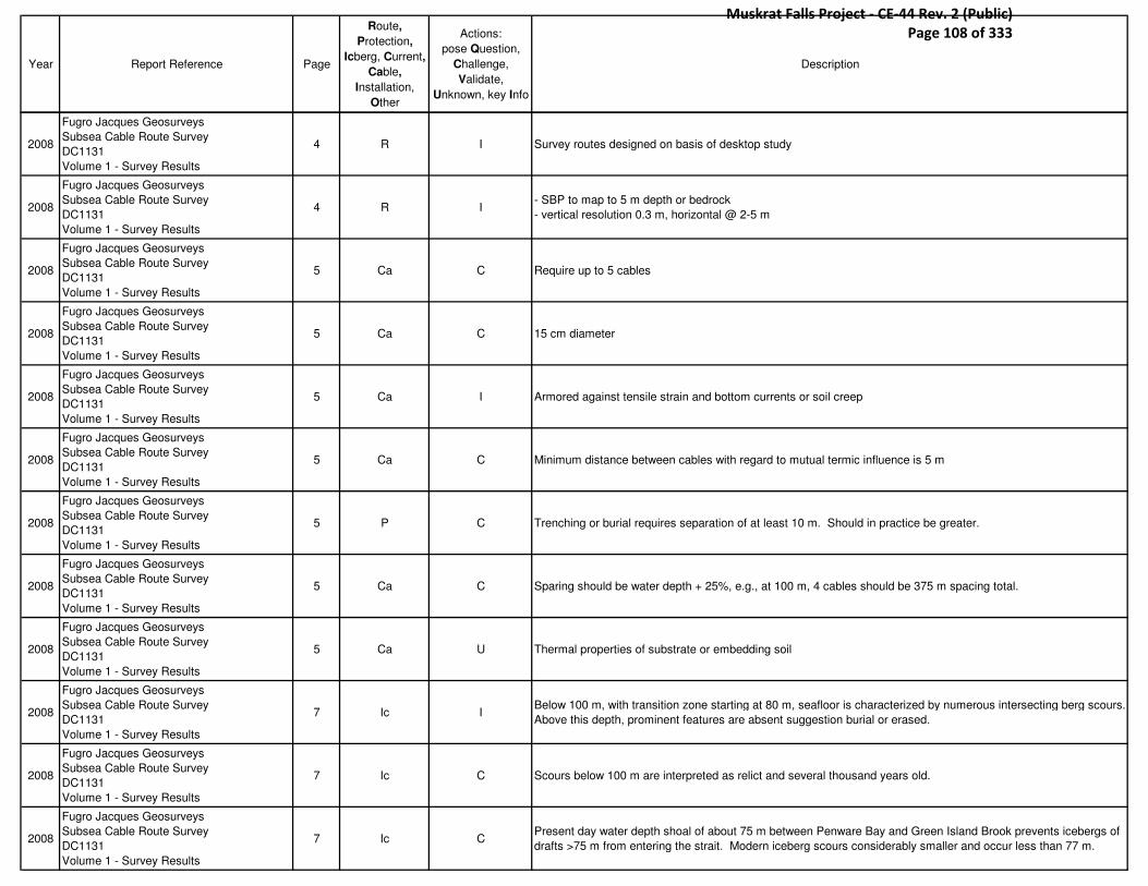
Year Report Reference Page
Route,
Protection,
Icberg, Current,
Cable,
Installation,
Other
Actions:
pose Question,
Challenge,
Validate,
Unknown, key Info
Description
2008
Fugro Jacques Geosurveys
Subsea Cable Route Survey
DC1131
Volume 1 - Survey Results
4 R I Survey routes designed on basis of desktop study
2008
Fugro Jacques Geosurveys
Subsea Cable Route Survey
DC1131
Volume 1 - Survey Results
4 R I- SBP to map to 5 m depth or bedrock
- vertical resolution 0.3 m, horizontal @ 2-5 m
2008
Fugro Jacques Geosurveys
Subsea Cable Route Survey
DC1131
Volume 1 - Survey Results
5 Ca C Require up to 5 cables
2008
Fugro Jacques Geosurveys
Subsea Cable Route Survey
DC1131
Volume 1 - Survey Results
5 Ca C 15 cm diameter
2008
Fugro Jacques Geosurveys
Subsea Cable Route Survey
DC1131
Volume 1 - Survey Results
5 Ca I Armored against tensile strain and bottom currents or soil creep
2008
Fugro Jacques Geosurveys
Subsea Cable Route Survey
DC1131
Volume 1 - Survey Results
5 Ca C Minimum distance between cables with regard to mutual termic influence is 5 m
2008
Fugro Jacques Geosurveys
Subsea Cable Route Survey
DC1131
Volume 1 - Survey Results
5 P C Trenching or burial requires separation of at least 10 m. Should in practice be greater.
2008
Fugro Jacques Geosurveys
Subsea Cable Route Survey
DC1131
Volume 1 - Survey Results
5 Ca C Sparing should be water depth + 25%, e.g., at 100 m, 4 cables should be 375 m spacing total.
2008
Fugro Jacques Geosurveys
Subsea Cable Route Survey
DC1131
Volume 1 - Survey Results
5 Ca U Thermal properties of substrate or embedding soil
2008
Fugro Jacques Geosurveys
Subsea Cable Route Survey
DC1131
Volume 1 - Survey Results
7 Ic IBelow 100 m, with transition zone starting at 80 m, seafloor is characterized by numerous intersecting berg scours.
Above this depth, prominent features are absent suggestion burial or erased.
2008
Fugro Jacques Geosurveys
Subsea Cable Route Survey
DC1131
Volume 1 - Survey Results
7 Ic C Scours below 100 m are interpreted as relict and several thousand years old.
2008
Fugro Jacques Geosurveys
Subsea Cable Route Survey
DC1131
Volume 1 - Survey Results
7 Ic CPresent day water depth shoal of about 75 m between Penware Bay and Green Island Brook prevents icebergs of
drafts >75 m from entering the strait. Modern iceberg scours considerably smaller and occur less than 77 m.
Muskrat Falls Project - CE-44 Rev. 2 (Public) Page 108 of 333

Year Report Reference Page
Route,
Protection,
Icberg, Current,
Cable,
Installation,
Other
Actions:
pose Question,
Challenge,
Validate,
Unknown, key Info
Description
2008
Fugro Jacques Geosurveys
Subsea Cable Route Survey
DC1131
Volume 1 - Survey Results
7 Ic CFeatures previously thought to be ribbed moraines occur in zone of relict iceberg scours, and are in fact bouldery
berms
2008
Fugro Jacques Geosurveys
Subsea Cable Route Survey
DC1131
Volume 1 - Survey Results
7 R I Figure 2.2 - prominent physiographic seafloor features
2008
Fugro Jacques Geosurveys
Subsea Cable Route Survey
DC1131
Volume 1 - Survey Results
7 R I Bathy data connected to LLWLT
2008
Fugro Jacques Geosurveys
Subsea Cable Route Survey
DC1131
Volume 1 - Survey Results
14 R I Survey data presented in 10 horizontal alignment sheets
2008
Fugro Jacques Geosurveys
Subsea Cable Route Survey
DC1131
Volume 1 - Survey Results
16 P I Max plough penetration in 1984 was 80 cm
2008
Fugro Jacques Geosurveys
Subsea Cable Route Survey
DC1131
Volume 1 - Survey Results
18 R I Lab. Side tidal zone slopes at 3-8 deg.
2008
Fugro Jacques Geosurveys
Subsea Cable Route Survey
DC1131
Volume 1 - Survey Results
18 R I Bedrock is Bradore formation sandstone on Lab. Side
2008
Fugro Jacques Geosurveys
Subsea Cable Route Survey
DC1131
Volume 1 - Survey Results
18 R I Eastern route: sand 16 m deep at 50 m depth between kp 0.8 and 0.9.
2008
Fugro Jacques Geosurveys
Subsea Cable Route Survey
DC1131
Volume 1 - Survey Results
21 Ic V WD 110, eastern route, scours with 2 m relief and 50-100 m wide, .5-2km long.
2008
Fugro Jacques Geosurveys
Subsea Cable Route Survey
DC1131
Volume 1 - Survey Results
28 R I 0.5-1.0 m high vertical steps in bedrock at KP 24-27. Stepped bedrock.
2008
Fugro Jacques Geosurveys
Subsea Cable Route Survey
DC1131
Volume 1 - Survey Results
41 R I
Glacial marine ridges are seen clearly on the isopach map, with discrete sediment thickening.
1. KP 25.3-25.5
2. KP 25.9-26
3. KP 26.7
4. KP 27
2008
Fugro Jacques Geosurveys
Subsea Cable Route Survey
DC1131
Volume 1 - Survey Results
41 Ic I200 m east of route at KP 20, between 67 and 69 m water depth, fresh iceberg scour, 160 m long, 2-7 m wide,
depth about 25 cm.
Muskrat Falls Project - CE-44 Rev. 2 (Public) Page 109 of 333

Year Report Reference Page
Route,
Protection,
Icberg, Current,
Cable,
Installation,
Other
Actions:
pose Question,
Challenge,
Validate,
Unknown, key Info
Description
2008
Fugro Jacques Geosurveys
Subsea Cable Route Survey
DC1131
Volume 1 - Survey Results
46 Ic I Scours at 48-77 m water depth near Forteau
2008
Fugro Jacques Geosurveys
Subsea Cable Route Survey
DC1131
Volume 1 - Survey Results
47 R I Fig. 4.18 - side scan sonar mosaic
2008
Fugro Jacques Geosurveys
Subsea Cable Route Survey
DC1131
Volume 1 - Survey Results
48 Ic V Table 4.1 - Fresh iceberg scours
2008
Fugro Jacques Geosurveys
Subsea Cable Route Survey
DC1131
Volume 1 - Survey Results
48 R I 17.5 km shortest route
2008
Fugro Jacques Geosurveys
Subsea Cable Route Survey
DC1131
Volume 1 - Survey Results
51 Ic V NL coast < 69 m (scours???)
2008
Fugro Jacques Geosurveys
Subsea Cable Route Survey
DC1131
Volume 1 - Survey Results
51 R I Sonar Contacts
2007
C-CORE
Ice scour risk in the Strait of Belle Isle and
Cabot Strait
2-3 P C Iceberg density is 20 times higher than in the Jeanne d'Arc Basin
2007
C-CORE
Ice scour risk in the Strait of Belle Isle and
Cabot Strait
2-8 P I 1979-1987, mean iceberg speed of 40 cm/s
2007
C-CORE
Ice scour risk in the Strait of Belle Isle and
Cabot Strait
3-4 P I table 3-1 - Variation in scour and pit depth w/water depth
2007
C-CORE
Ice scour risk in the Strait of Belle Isle and
Cabot Strait
3-6 P U Data for < 90 m was extrapolated
2007
C-CORE
Ice scour risk in the Strait of Belle Isle and
Cabot Strait
3-13 P IScours filled in so quickly that they weren’t detectable a year after their formation. Recommend to collect scour
data immediately after ice season.
2007
C-CORE
Ice scour risk in the Strait of Belle Isle and
Cabot Strait
5-14 P I Deepest scour in Beaufort Sea was 3.6 m.
2007
C-CORE
Ice scour risk in the Strait of Belle Isle and
Cabot Strait
5-23 P I Table 5-7, 5-25 - Pack ice and soil cover
2007
C-CORE
Ice scour risk in the Strait of Belle Isle and
Cabot Strait
2-1 P U
- field data unavailable
- insufficient mapping of the area
- rapid infilling of scour features
- data for iceberg trajectory is unknown
Muskrat Falls Project - CE-44 Rev. 2 (Public) Page 110 of 333

Year Report Reference Page
Route,
Protection,
Icberg, Current,
Cable,
Installation,
Other
Actions:
pose Question,
Challenge,
Validate,
Unknown, key Info
Description
2007
C-CORE
Ice scour risk in the Strait of Belle Isle and
Cabot Strait
3-1 P U Currently there is no scour data
2004
C-CORE
Iceberg scour risk in the SOBI
Prepared for SGE Acres
I P I Required cover depths of 3-5.5 m for 100 and 1000 year returns, respectively
2004
C-CORE
Iceberg scour risk in the SOBI
Prepared for SGE Acres
1-1 Ic I Largest number of bergs between May and June
2004
C-CORE
Iceberg scour risk in the SOBI
Prepared for SGE Acres
- Ic V An iceberg reaches the Cabot strait in 1980 (??)
2004
C-CORE
Iceberg scour risk in the SOBI
Prepared for SGE Acres
- Ic V 496 bergs were recorded by Belle Isle lighthouse keeper in 1858.
2004
C-CORE
Iceberg scour risk in the SOBI
Prepared for SGE Acres
- Ic C0.5 events for every 100 where 85>WD>75 m
0.1 events for every 100 WD>85
2004
C-CORE
Iceberg scour risk in the SOBI
Prepared for SGE Acres
- P V Previous studies aimed to beach and bury to 85 m
2004
C-CORE
Iceberg scour risk in the SOBI
Prepared for SGE Acres
2-1 Ic I No field data available for SOBI
2004
C-CORE
Iceberg scour risk in the SOBI
Prepared for SGE Acres
- Ic I Data required for grounding model is available
2004
C-CORE
Iceberg scour risk in the SOBI
Prepared for SGE Acres
2-5 Ic CAs opposed to C-CORE 2007, iceberg density is stated as 40x the Jeanne d'Arc region. [Reasoning was more ice
charts analyzed].
2008
Fugro Jacques Geosurveys
Proposed Subsea HVDC cable route - SOBI
Desktop Compilation Desk Study
DC1132
1 R I Bedrock is sandstone, limestone, dolomite w/shale.
2008
Fugro Jacques Geosurveys
Proposed Subsea HVDC cable route - SOBI
Desktop Compilation Desk Study
DC1132
- P I Plough: 0-80 cm penetration
2008
Fugro Jacques Geosurveys
Proposed Subsea HVDC cable route - SOBI
Desktop Compilation Desk Study
DC1132
2 P I Directional drilling is an option
Muskrat Falls Project - CE-44 Rev. 2 (Public) Page 111 of 333
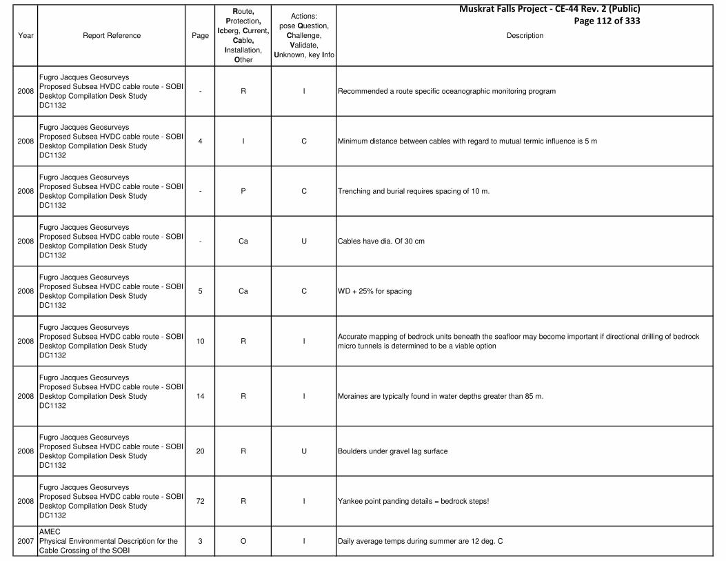
Year Report Reference Page
Route,
Protection,
Icberg, Current,
Cable,
Installation,
Other
Actions:
pose Question,
Challenge,
Validate,
Unknown, key Info
Description
2008
Fugro Jacques Geosurveys
Proposed Subsea HVDC cable route - SOBI
Desktop Compilation Desk Study
DC1132
- R I Recommended a route specific oceanographic monitoring program
2008
Fugro Jacques Geosurveys
Proposed Subsea HVDC cable route - SOBI
Desktop Compilation Desk Study
DC1132
4 I C Minimum distance between cables with regard to mutual termic influence is 5 m
2008
Fugro Jacques Geosurveys
Proposed Subsea HVDC cable route - SOBI
Desktop Compilation Desk Study
DC1132
- P C Trenching and burial requires spacing of 10 m.
2008
Fugro Jacques Geosurveys
Proposed Subsea HVDC cable route - SOBI
Desktop Compilation Desk Study
DC1132
- Ca U Cables have dia. Of 30 cm
2008
Fugro Jacques Geosurveys
Proposed Subsea HVDC cable route - SOBI
Desktop Compilation Desk Study
DC1132
5 Ca C WD + 25% for spacing
2008
Fugro Jacques Geosurveys
Proposed Subsea HVDC cable route - SOBI
Desktop Compilation Desk Study
DC1132
10 R IAccurate mapping of bedrock units beneath the seafloor may become important if directional drilling of bedrock
micro tunnels is determined to be a viable option
2008
Fugro Jacques Geosurveys
Proposed Subsea HVDC cable route - SOBI
Desktop Compilation Desk Study
DC1132
14 R I Moraines are typically found in water depths greater than 85 m.
2008
Fugro Jacques Geosurveys
Proposed Subsea HVDC cable route - SOBI
Desktop Compilation Desk Study
DC1132
20 R U Boulders under gravel lag surface
2008
Fugro Jacques Geosurveys
Proposed Subsea HVDC cable route - SOBI
Desktop Compilation Desk Study
DC1132
72 R I Yankee point panding details = bedrock steps!
2007
AMEC
Physical Environmental Description for the
Cable Crossing of the SOBI
3 O I Daily average temps during summer are 12 deg. C
Muskrat Falls Project - CE-44 Rev. 2 (Public) Page 112 of 333

Year Report Reference Page
Route,
Protection,
Icberg, Current,
Cable,
Installation,
Other
Actions:
pose Question,
Challenge,
Validate,
Unknown, key Info
Description
2007
AMEC
Physical Environmental Description for the
Cable Crossing of the SOBI
4 Ic I Sea Ice begins to dissipate by the end of March
2007
AMEC
Physical Environmental Description for the
Cable Crossing of the SOBI
- O I There is a lot of good climate data
2007
AMEC
Physical Environmental Description for the
Cable Crossing of the SOBI
15 I IApril to June - Northeast & SW winds
July-Dec - SW to W
2007
AMEC
Physical Environmental Description for the
Cable Crossing of the SOBI
17 O ITidal energies flow in a counter clockwise fashion around the gulf increasing in height from 0.6 m at the Magdalen
Islands to nearly 5 m at Quebec city.
2007
AMEC
Physical Environmental Description for the
Cable Crossing of the SOBI
19 O I
Avg. summer temps are 10-11 deg C
- below 60 m, -0.4 to 3.5 deg C
- winter, -1.8 to 2.73 deg. C
2007
AMEC
Physical Environmental Description for the
Cable Crossing of the SOBI
22 I V
Waves: 7 m @ 0.001% of the time, 0-0.5 @ 54%, 2-2.5 @ 2%
Hs exceeded 2 m 8% of the time
7.3 m was maximum recorded
2007
AMEC
Physical Environmental Description for the
Cable Crossing of the SOBI
24 I I Wave data
2007
AMEC
Physical Environmental Description for the
Cable Crossing of the SOBI
35 C I Summary of max. current speeds
2007
AMEC
Physical Environmental Description for the
Cable Crossing of the SOBI
38 C I BIO current measurements
2007
AMEC
Physical Environmental Description for the
Cable Crossing of the SOBI
41 I I
Tides - 2 highs and lows every 24-25 hours
- mean small tide is 0.44, max 1 m
- mean large tide is 1.6 m, max 2.2 m
2007
AMEC
Physical Environmental Description for the
Cable Crossing of the SOBI
- I I Appendices: climate, wave, current data
2008Jacques Whitford for FJG
Strait of Belle Isle constraint Mapping1 O I No primary sewage treatment in study area communities
2008Jacques Whitford for FJG
Strait of Belle Isle constraint Mapping- O I fish disposal sites at L'Anse au Loup and Red Bay
2008Jacques Whitford for FJG
Strait of Belle Isle constraint Mapping- R U Ordinances remaining at Raleigh site?
2008Jacques Whitford for FJG
Strait of Belle Isle constraint Mapping3 I I 40 shipwrecks in area, with 1 arch. Important (Raleigh)
2008Jacques Whitford for FJG
Strait of Belle Isle constraint Mapping- R U Historical resource assessments of cable landing sites may be required.
2008Jacques Whitford for FJG
Strait of Belle Isle constraint Mapping- R I 100 m exclusion zones recommended
2008Jacques Whitford for FJG
Strait of Belle Isle constraint Mapping- R U PAO may require video
Muskrat Falls Project - CE-44 Rev. 2 (Public) Page 113 of 333

Year Report Reference Page
Route,
Protection,
Icberg, Current,
Cable,
Installation,
Other
Actions:
pose Question,
Challenge,
Validate,
Unknown, key Info
Description
2008Jacques Whitford for FJG
Strait of Belle Isle constraint Mapping4 O I Several small craft harbors
2008Jacques Whitford for FJG
Strait of Belle Isle constraint Mapping- P I Scallop dredging at 45-55 m
2008Jacques Whitford for FJG
Strait of Belle Isle constraint Mapping8 P I Shrimps > 150-350 m (more fishing info can be found here)
2008Jacques Whitford for FJG
Strait of Belle Isle constraint Mapping- O I Appendix E: Earthquake Magnitude
2007
C-CORE
Screening study of production options for
Labrador Gas
V1 of2
I P I Risk analysis indicates deep cover depths of > 4 m
2007
C-CORE
Screening study of production options for
Labrador Gas
V1 of2
vi Ic V Ice scour risk is low for WD > 250 m.
2007
C-CORE
Screening study of production options for
Labrador Gas
V1 of2
2-16 Ic V Iceberg scour formulae
2007
C-CORE
Screening study of production options for
Labrador Gas
V1 of2
2-25 Ic V Table 2-7 Unfactored iceberg design loads
2007
C-CORE
Screening study of production options for
Labrador Gas
V1 of2
2-31 P U Trawler scour depths
2007
C-CORE
Screening study of production options for
Labrador Gas
V1 of2
2-31 P I DNV publications 2001, 2006 and HSE 1999 on trawling details
2007
C-CORE
Screening study of production options for
Labrador Gas
V1 of2
2-35 R U Sedimentation rates
2007
C-CORE
Screening study of production options for
Labrador Gas
V1 of2
3-1 R U Soil properties
2007
C-CORE
Screening study of production options for
Labrador Gas
V1 of2
3-3 R U Subgouge deformation extents
2007
C-CORE
Screening study of production options for
Labrador Gas
V1 of2
3-4 R U Frost heave risks
Muskrat Falls Project - CE-44 Rev. 2 (Public) Page 114 of 333

Year Report Reference Page
Route,
Protection,
Icberg, Current,
Cable,
Installation,
Other
Actions:
pose Question,
Challenge,
Validate,
Unknown, key Info
Description
2007
C-CORE
Screening study of production options for
Labrador Gas
V1 of2
3-8 O I Limit state and probabilistic design, stress vs. strain, upper bound design approach
2007
C-CORE
Screening study of production options for
Labrador Gas
V1 of2
3-16 P I HDD - a series of pulls?
2007
C-CORE
Screening study of production options for
Labrador Gas
V1 of2
3-17 P U Hybrid HDD technology
2007
C-CORE
Screening study of production options for
Labrador Gas
V1 of2
3-44 P I TTD - largest trench depth calculations
2007
C-CORE
Screening study of production options for
Labrador Gas
V1 of2
3-48 P I Table 3-9, pipeline plough companies
2007
C-CORE
Screening study of production options for
Labrador Gas
V1 of2
3-52 P I Table 3-10 - Jet trenchers and manufacturers
2007
C-CORE
Screening study of production options for
Labrador Gas
V1 of2
3-53 P I Cutting trenchers - buoyancy tanks
2007
C-CORE
Screening study of production options for
Labrador Gas
V1 of2
3-54 P Q Technip TM09
2007
C-CORE
Screening study of production options for
Labrador Gas
V1 of2
3-57 P I Cutter trenchers
2007
C-CORE
Screening study of production options for
Labrador Gas
V1 of2
5-61 Ca U Cable stability requirements
2007
C-CORE
Screening study of production options for
Labrador Gas
V1 of2
5-67 P I Self pipeline burial - interesting technology, not applicable to SOBI
2007
C-CORE
Screening study of production options for
Labrador Gas
V1 of2
5-75 R I Thaw and consolidation settlement
Muskrat Falls Project - CE-44 Rev. 2 (Public) Page 115 of 333
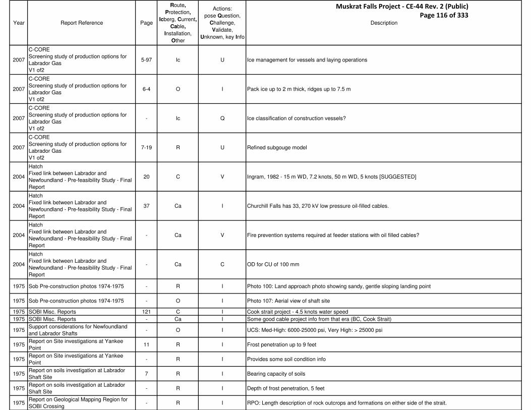
Year Report Reference Page
Route,
Protection,
Icberg, Current,
Cable,
Installation,
Other
Actions:
pose Question,
Challenge,
Validate,
Unknown, key Info
Description
2007
C-CORE
Screening study of production options for
Labrador Gas
V1 of2
5-97 Ic U Ice management for vessels and laying operations
2007
C-CORE
Screening study of production options for
Labrador Gas
V1 of2
6-4 O I Pack ice up to 2 m thick, ridges up to 7.5 m
2007
C-CORE
Screening study of production options for
Labrador Gas
V1 of2
- Ic Q Ice classification of construction vessels?
2007
C-CORE
Screening study of production options for
Labrador Gas
V1 of2
7-19 R U Refined subgouge model
2004
Hatch
Fixed link between Labrador and
Newfoundland - Pre-feasibility Study - Final
Report
20 C V Ingram, 1982 - 15 m WD, 7.2 knots, 50 m WD, 5 knots [SUGGESTED]
2004
Hatch
Fixed link between Labrador and
Newfoundland - Pre-feasibility Study - Final
Report
37 Ca I Churchill Falls has 33, 270 kV low pressure oil-filled cables.
2004
Hatch
Fixed link between Labrador and
Newfoundland - Pre-feasibility Study - Final
Report
- Ca V Fire prevention systems required at feeder stations with oil filled cables?
2004
Hatch
Fixed link between Labrador and
Newfoundland - Pre-feasibility Study - Final
Report
- Ca C OD for CU of 100 mm
1975 Sob Pre-construction photos 1974-1975 - R I Photo 100: Land approach photo showing sandy, gentle sloping landing point
1975 Sob Pre-construction photos 1974-1975 - O I Photo 107: Aerial view of shaft site
1975 SOBI Misc. Reports 121 C I Cook strait project - 4.5 knots water speed
1975 SOBI Misc. Reports - Ca I Some good cable project info from that era (BC, Cook Strait)
1975Support considerations for Newfoundland
and Labrador Shafts- O I UCS: Med-High: 6000-25000 psi, Very High: > 25000 psi
1975Report on Site investigations at Yankee
Point11 R I Frost penetration up to 9 feet
1975Report on Site investigations at Yankee
Point- R I Provides some soil condition info
1975Report on soils investigation at Labrador
Shaft Site7 R I Bearing capacity of soils
1975Report on soils investigation at Labrador
Shaft Site- R I Depth of frost penetration, 5 feet
1975Report on Geological Mapping Region for
SOBI Crossing- R I RPO: Length description of rock outcrops and formations on either side of the strait.
Muskrat Falls Project - CE-44 Rev. 2 (Public) Page 116 of 333

Year Report Reference Page
Route,
Protection,
Icberg, Current,
Cable,
Installation,
Other
Actions:
pose Question,
Challenge,
Validate,
Unknown, key Info
Description
1976 Offshore Seismic Survey 8 R IReasons for bad recording in the survey lines was probably due to very strong winds which caused strong lateral
motion of the vessel.
1976Report on Offshore Drilling and Coring
Program SOBI- O C
"It is currently our opinion that probably no drill ship or rig exists with equipment to handle all the conditions that
can prevail in the Strait."
1976Report on Offshore Drilling and Coring
Program SOBI- O C Drill ship used was not ideal.
1976Report on Offshore Drilling and Coring
Program SOBI- O C Another company proposed a larger dia. Drill string less prone to bending. Proposal was not pursued.
1976Report on Offshore Drilling and Coring
Program SOBI- O C
Geocon stated that standard drilling equipment could not handle the conditions. Exploration company was
cheaper, so they were selected. The ultimate decision was based on cost and cost alone.
1976Report on Offshore Drilling and Coring
Program SOBI- C C Current reverses every 6 hours.
1976Report on Offshore Drilling and Coring
Program SOBI- C C Tidal flow on bottom can reverse direction as much as 3 hours earlier. Surface current up to 5 knots.
1976Report on Offshore Drilling and Coring
Program SOBI- O C Used local fishing vessels to handle ship's anchors.
1976Report on Offshore Drilling and Coring
Program SOBI- O C Built after WWII for handling sub nets. 170 feet long.
1976Report on Offshore Drilling and Coring
Program SOBI27 O I E/R flooded en route to SOBI
1976Report on Offshore Drilling and Coring
Program SOBI- O I STBD main generator filled
1976Report on Offshore Drilling and Coring
Program SOBI- O I Power at half-capacity during drilling
1976Report on Offshore Drilling and Coring
Program SOBI- O I Bow thrusters were down and couldn't be used at any time.
1976Report on Offshore Drilling and Coring
Program SOBI- O I No reserve power for maneuvering.
1976Report on Offshore Drilling and Coring
Program SOBI- O I Lost drill bit and bottom equipment three times.
1976Report on Offshore Drilling and Coring
Program SOBI28 O I So much vibration experienced on drill string, it unscrewed.
1976Report on Offshore Drilling and Coring
Program SOBI- O I Lost drill bit under good weather and good conditions.
1976Report on Offshore Drilling and Coring
Program SOBI- O I Lost bottom end of string when 4-5" pipe failed
1976Report on Offshore Drilling and Coring
Program SOBI- O I Drill shaft failed.
1976Report on Offshore Drilling and Coring
Program SOBI- R I Damaged tool while trying to penetrate the bottom.
1976Report on Offshore Drilling and Coring
Program SOBI- O I Tongs failed that were used to separate string segments.
1976Report on Offshore Drilling and Coring
Program SOBI29 O I Bent drill string
1976Report on Offshore Drilling and Coring
Program SOBI30 I I Vortex issues with string
1976Report on Offshore Drilling and Coring
Program SOBI30 O I Anchors slipped
Muskrat Falls Project - CE-44 Rev. 2 (Public) Page 117 of 333
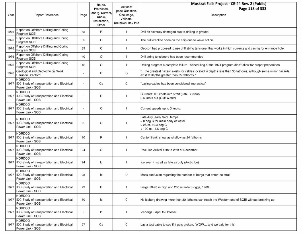
Year Report Reference Page
Route,
Protection,
Icberg, Current,
Cable,
Installation,
Other
Actions:
pose Question,
Challenge,
Validate,
Unknown, key Info
Description
1976Report on Offshore Drilling and Coring
Program SOBI32 R I Drill bit severely damaged due to drilling in ground.
1976Report on Offshore Drilling and Coring
Program SOBI35 O I The hull cracked open on the ship due to wave action.
1976Report on Offshore Drilling and Coring
Program SOBI39 C I Geocon had proposed to use drill string tensioner that works in high currents and casing for entrance hole.
1976Report on Offshore Drilling and Coring
Program SOBI40 O I Drill string tensioners had been recommended
1976Report on Offshore Drilling and Coring
Program SOBI42 O I Drilling program a complete failure. Scheduling of the 1974 program didn't allow for proper preparation.
1976Geological and Geotechnical Work
Harrison Bradford- R C
"…the greatest hazard exists for cables located in depths less than 35 fathoms, although some minor hazards
exist at depths greater than 35 fathoms."
1977
NORDCO
IDC Study of transportation and Electrical
Power Link - SOBI
- Ca C "Laying cables has been considered impractical"
1977
NORDCO
IDC Study of transportation and Electrical
Power Link - SOBI
- C ICurrents: 0.5 knots into strait (Lab. Current)
0.6 knots out (Gulf Water)
1977
NORDCO
IDC Study of transportation and Electrical
Power Link - SOBI
- C I Current speeds up to 3 knots.
1977
NORDCO
IDC Study of transportation and Electrical
Power Link - SOBI
8 O I
Late July, early Sept. temps:
< 0 deg C for main body of water
> 25 m, 10.3 deg C
< 100 m, -1.6 deg C
1977
NORDCO
IDC Study of transportation and Electrical
Power Link - SOBI
10 R I Center Bank' shoal as shallow as 24 fathoms
1977
NORDCO
IDC Study of transportation and Electrical
Power Link - SOBI
24 O I Pack Ice Arrival 15th to 25th of December
1977
NORDCO
IDC Study of transportation and Electrical
Power Link - SOBI
24 Ic I Ice seen in strait as late as July (Arctic Ice)
1977
NORDCO
IDC Study of transportation and Electrical
Power Link - SOBI
28 Ic U Mass confusion regarding the number of bergs that enter the strait
1977
NORDCO
IDC Study of transportation and Electrical
Power Link - SOBI
29 Ic I Bergs 50-70 m high and 200 m wide [Briggs, 1968]
1977
NORDCO
IDC Study of transportation and Electrical
Power Link - SOBI
30 Ic C No iceberg drawing more than 30 fathoms can reach the Western end of SOBI without breaking up
1977
NORDCO
IDC Study of transportation and Electrical
Power Link - SOBI
- Ic I Icebergs - April to October
1977
NORDCO
IDC Study of transportation and Electrical
Power Link - SOBI
57 Ca C Lay a test cable to see if it gets broken. [WOW… and we paid for this]
Muskrat Falls Project - CE-44 Rev. 2 (Public) Page 118 of 333

Year Report Reference Page
Route,
Protection,
Icberg, Current,
Cable,
Installation,
Other
Actions:
pose Question,
Challenge,
Validate,
Unknown, key Info
Description
1977Department of Mines and Energy
Proposed Belle Isle Cable Crossing8 C I Tides from 2-3 knots, up to 5 knots combined
1977Department of Mines and Energy
Proposed Belle Isle Cable Crossing9 O I There is little statistical current data.
1977Department of Mines and Energy
Proposed Belle Isle Cable Crossing9 I C Ice free between Aug and December
1977Department of Mines and Energy
Proposed Belle Isle Cable Crossing12 I Q Skagerrak, reliability for four cables at 250 kV
1977Department of Mines and Energy
Proposed Belle Isle Cable Crossing- C Q Cook Inlet - 10 knots current
1977Department of Mines and Energy
Proposed Belle Isle Cable Crossing16 Ca Q
Sweden-Denmark
- Several faults occurred on the cable
- Otter boards caused the damage
1977Department of Mines and Energy
Proposed Belle Isle Cable Crossing24 P U Otter board details
1977Department of Mines and Energy
Proposed Belle Isle Cable Crossing27 Ca I Cost in 1977, 2 cables, supply and install, burial, at 50-60 m.
1978
NORDCO
Interim Report, Current Metering Program
SOBI
1 C I Emphasis placed on bottom currents
1978
NORDCO
Interim Report, Current Metering Program
SOBI
- C C Numerous issues with battery failures, deployment, etc.
1978
NORDCO
Interim Report, Current Metering Program
SOBI
22 C I Preliminary assessment
1978
NORDCO
Interim Report, Current Metering Program
SOBI
28 C V Currents in upper level as high as 3.2 knots.
1979 Misc Notes - Ic V "Bergs have grounded in water 360 feet deep near the entrance to the Strait"
1979 Misc Notes - R I "Furrows have been found 2 miles long, 100' wide and 20' deep"
1979 Misc Notes - Ca IBC cable details:
525 kV, at 37 km, $23M supply and install
1980Kenting
Interpretation Report for Marine SurveyI Ic I Eight iceberg scour marks occur in the Western area in WD ranging from 36 m to 83 m. - 2 found at 83 m.
1980Kenting
Interpretation Report for Marine Survey11 Ic I
Iceberg scours, SSS data, lines 1220 and 41
Scour dimensions 250 m x 10 m x 1 m and 100 m x 8 m x 1m
1980Kenting
Interpretation Report for Marine Survey14 Ic V
Iceberg scours - ten found in survey area
lines: 510, 520, 530, 50 and 51 - one scour, 400 m long
1980Kenting
Interpretation Report for Marine Survey- Ic V
Small scours (<100 m long)
two scours on line 460, one on 480 and 530
1979
Shawmont
SOBI Cable Crossing, Preliminary
Engineering Report
- Ca I Summary - recommended that cable suppliers and installers visit the site before they bid
1979
Shawmont
SOBI Cable Crossing, Preliminary
Engineering Report
- Ic VThe identification of scours in the 1974 survey contradicts 1968 and 1973 survey which had new marks. Some
identified in 1974 located in depths in excess of 300 feet.
Muskrat Falls Project - CE-44 Rev. 2 (Public) Page 119 of 333

Year Report Reference Page
Route,
Protection,
Icberg, Current,
Cable,
Installation,
Other
Actions:
pose Question,
Challenge,
Validate,
Unknown, key Info
Description
1979
Shawmont
SOBI Cable Crossing, Preliminary
Engineering Report
- C V 1963 Fraquharson and Bailey found 3 knots to be greatest current
1979
Shawmont
SOBI Cable Crossing, Preliminary
Engineering Report
- C U Recommend installing wave rider buoy for several months
1979
Shawmont
SOBI Cable Crossing, Preliminary
Engineering Report
2.9 P I Doors/Otter Boards - 6 x 4', 500 lbs each
1979
Shawmont
SOBI Cable Crossing, Preliminary
Engineering Report
- R Q Ability to mark the charts with cable routing
??? [NORCO Current Study] iii C V - Max currents 4 knots at 12 m from bottom
1981
Beaver Dredging Company
Marine Borings and Surveys
Volume 1 - Executive Summary
10 C V Max water depths 115 m with currents up to 4 knots
1981
Beaver Dredging Company
Marine Borings and Surveys
Volume 1 - Executive Summary
19 Ic V
- Bottom is not conducive to the preservation of iceberg scour marks
- The veneer of sediment is not suited to preservation of scour imprints
- 105 m scour found is most likely not from recent scour
1981
Beaver Dredging Company
Marine Borings and Surveys
Volume 1 - Executive Summary
21 C V 4.1 knots of current max
1981
Beaver Dredging Company
Marine Borings and Surveys
Volume 1 - Executive Summary
24 R I fig 3.2.1 - Borehole locations across the Strait
1981
Beaver Dredging Company
Marine Borings and Surveys
Volume 1 - Executive Summary
25 O I ASK - dynamic positioning systems used by Rock Giant
1981
Beaver Dredging Company
Marine Borings and Surveys
Volume 1 - Executive Summary
30 R I Summary of drilled depths in overburden and rock
1981
Beaver Dredging Company
Marine Borings and Surveys
Volume 1 - Executive Summary
42 I U Weather can be different on both sides of the Strait, and in the middle
1981
Beaver Dredging Company
Marine Borings and Surveys
Volume 1 - Executive Summary
44 Ic C Used long liners to tow away growlers
1981
Beaver Dredging Company
Marine Borings and Surveys
Volume 2 - Marine Surveys
- R I Excellent bottom profile data
1981
Beaver Dredging Company
Marine Borings and Surveys
Volume 2 - Marine Surveys
97 Ic V Thin score marks in area - believed to be caused by trawl boards, and not bergs
1981
Beaver Dredging Company
Marine Borings and Surveys
Volume 2 - Marine Surveys
98 Ic V Zone E: two icebergs features - pock mark and distinct scour (100 m)
1981
Beaver Dredging Company
Marine Borings and Surveys
Volume 2 - Marine Surveys
100 O I Appendix A.2 - Measured tidal extremes
Muskrat Falls Project - CE-44 Rev. 2 (Public) Page 120 of 333
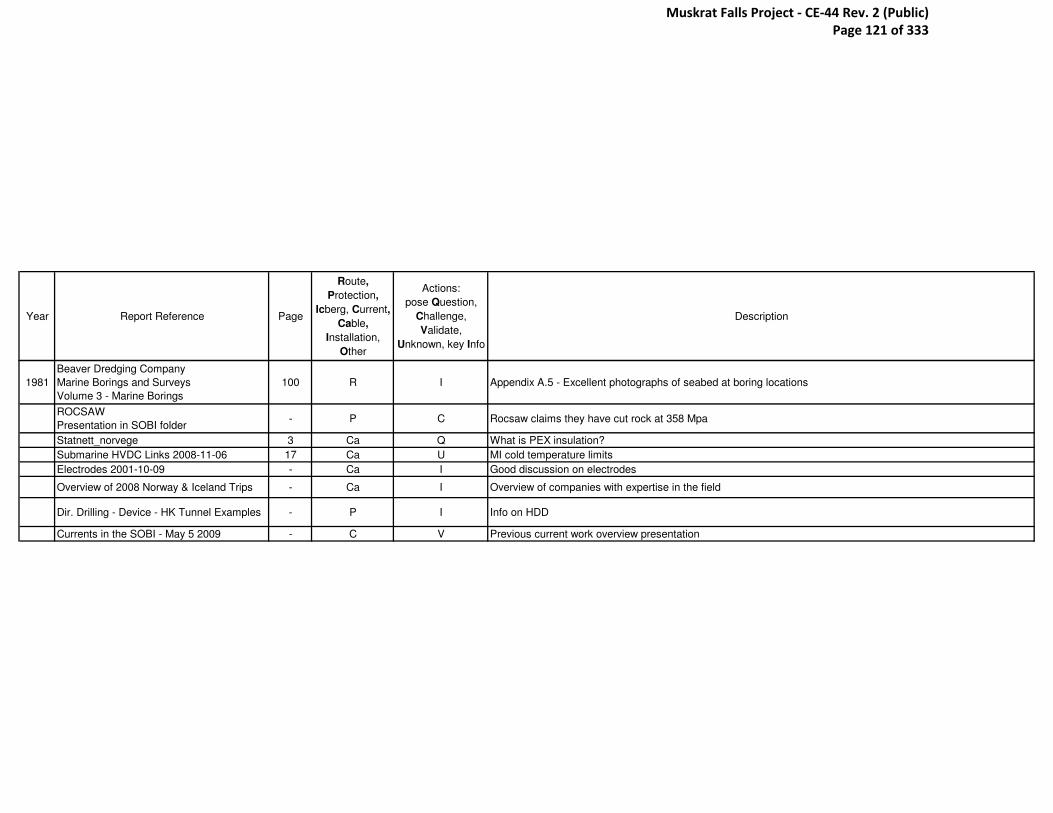
Year Report Reference Page
Route,
Protection,
Icberg, Current,
Cable,
Installation,
Other
Actions:
pose Question,
Challenge,
Validate,
Unknown, key Info
Description
1981
Beaver Dredging Company
Marine Borings and Surveys
Volume 3 - Marine Borings
100 R I Appendix A.5 - Excellent photographs of seabed at boring locations
ROCSAW
Presentation in SOBI folder- P C Rocsaw claims they have cut rock at 358 Mpa
Statnett_norvege 3 Ca Q What is PEX insulation?
Submarine HVDC Links 2008-11-06 17 Ca U MI cold temperature limits
Electrodes 2001-10-09 - Ca I Good discussion on electrodes
Overview of 2008 Norway & Iceland Trips - Ca I Overview of companies with expertise in the field
Dir. Drilling - Device - HK Tunnel Examples - P I Info on HDD
Currents in the SOBI - May 5 2009 - C V Previous current work overview presentation
Muskrat Falls Project - CE-44 Rev. 2 (Public) Page 121 of 333

Appendix D- ABB Cable Cost
Muskrat Falls Project - CE-44 Rev. 2 (Public) Page 122 of 333

To: [email protected] <[email protected]>,
Cc:
Bcc:
Subject: Fw: Budgetary Pricing for Cables and Vessels
----- Forwarded by Tim Ralph/NLHydro on 09/14/2010 09:57 AM -----
From: Bengt Johnnerfelt <[email protected]>To: [email protected]: [email protected], [email protected],
[email protected]: 09/14/2010 09:55 AMSubject: Re: Budgetary Pricing for Cables and Vessels
Tim,
Here are our budgetary prices (+/- 30%) They are in Swedish Krona ,SEK, to avoid fluctuations in currencies . Please note that the prices are per cable and you will need two cables as this will be a bipole .
Best regards,Bengt
Muskrat Falls Project - CE-44 Rev. 2 (Public) Page 123 of 333

Appendix E- Nexans HDD Pulling Tension Confirmation
Muskrat Falls Project - CE-44 Rev. 2 (Public) Page 124 of 333

Tim, Our engineering team has confirmed that allowable max pulling tension for the applicable cable design will
exceed the estimated pulling force required. Therefore, from a cable point of view the pull-ins can be
achieved. Best regards Morten Langnes Export Sales Manager Nexans Norway AS, Energy Division T: +47 22886293 | M: +47 99571588
Strait of Belle Isle Current Information - pulling tension Morten LANGNES to: [email protected] 09/09/2010 05:57 AM Cc: "[email protected]" Show Details History: This message has been replied to and forwarded.
Page 1 of 1
9/9/2010file://M:\Documents and Settings\timralcr\Local Settings\Temp\f\notes2EBE8C\~web2975....
Muskrat Falls Project - CE-44 Rev. 2 (Public) Page 125 of 333

Appendix F- Nexans Cable Cost
Muskrat Falls Project - CE-44 Rev. 2 (Public) Page 126 of 333

FwFwFwFw:::: Strait of Belle Isle Current InformationStrait of Belle Isle Current InformationStrait of Belle Isle Current InformationStrait of Belle Isle Current InformationTim RalphTim RalphTim RalphTim Ralph to: Tim Ralph 09/03/2010 10:23 AM
----- Forwarded by Tim Ralph/NLHydro on 09/03/2010 10:23 AM -----
From: Morten LANGNES <[email protected]>To: "[email protected]" <[email protected]>Cc: "[email protected]" <[email protected]>Date: 09/01/2010 10:54 AMSubject: RE: Strait of Belle Isle Current Information
Tim,
I have updated our budget estimate to take into account that we double the amount of steel armour
compared with the data sheets you received earlier.
The above will be our early information to assist you in your effort to meet the gate deadline . It is my
intention to compile the various pieces of information into a document later .
I hope this is sufficient at the moment, otherwise let me know if you need further details of any kind .
Best regards
Morten Langnes
Export Sales Manager
Nexans Norway AS, Energy Division
T: +47 22886293 | M: +47 99571588
Muskrat Falls Project - CE-44 Rev. 2 (Public) Page 127 of 333

Appendix G- Nexans MI Cross Sectional Breakdown
Muskrat Falls Project - CE-44 Rev. 2 (Public) Page 128 of 333

Appendix H- Prysmian Pulling Tension
Muskrat Falls Project - CE-44 Rev. 2 (Public) Page 129 of 333

Appendix I- Prysmian Study Results
Muskrat Falls Project - CE-44 Rev. 2 (Public) Page 130 of 333

Appendix J- Cu and Al Budgetary Costs
Muskrat Falls Project - CE-44 Rev. 2 (Public) Page 131 of 333
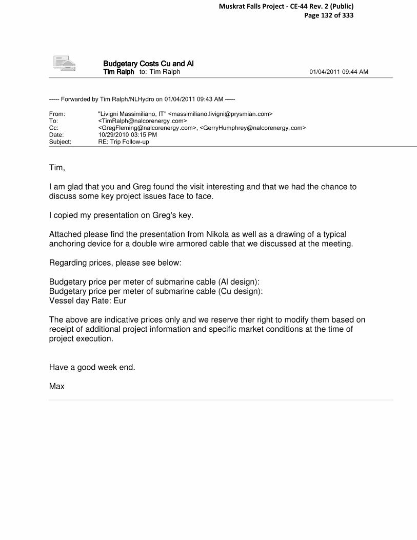
Budgetary Costs Cu and AlBudgetary Costs Cu and AlBudgetary Costs Cu and AlBudgetary Costs Cu and AlTim RalphTim RalphTim RalphTim Ralph to: Tim Ralph 01/04/2011 09:44 AM
----- Forwarded by Tim Ralph/NLHydro on 01/04/2011 09:43 AM -----
From: "Livigni Massimiliano, IT" <[email protected]>To: <[email protected]>Cc: <[email protected]>, <[email protected]>Date: 10/29/2010 03:15 PMSubject: RE: Trip Follow-up
Tim, I am glad that you and Greg found the visit interesting and that we had the chance to discuss some key project issues face to face. I copied my presentation on Greg's key. Attached please find the presentation from Nikola as well as a drawing of a typical anchoring device for a double wire armored cable that we discussed at the meeting. Regarding prices, please see below: Budgetary price per meter of submarine cable (Al design): Budgetary price per meter of submarine cable (Cu design): Vessel day Rate: Eur The above are indicative prices only and we reserve ther right to modify them based on receipt of additional project information and specific market conditions at the time of project execution. Have a good week end. Max
Muskrat Falls Project - CE-44 Rev. 2 (Public) Page 132 of 333

Appendix K- Vessel Traffic
Muskrat Falls Project - CE-44 Rev. 2 (Public) Page 133 of 333
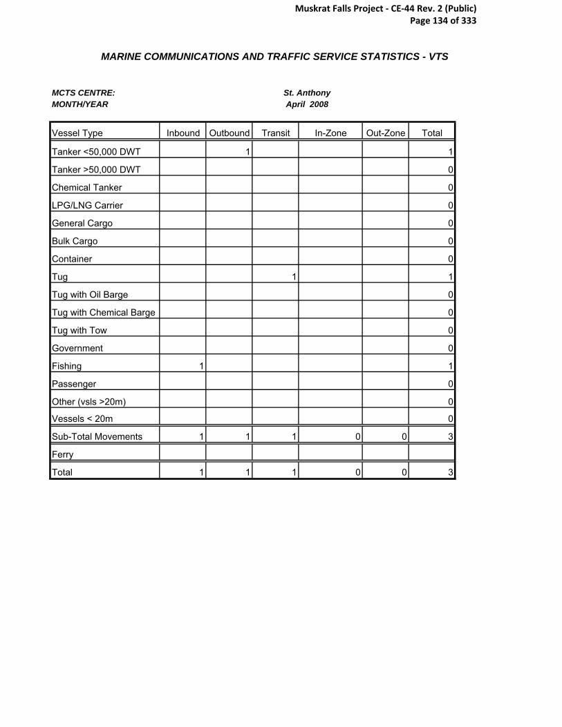
MARINE COMMUNICATIONS AND TRAFFIC SERVICE STATISTICS - VTS
MCTS CENTRE:MONTH/YEAR
Vessel Type Inbound Outbound Transit In-Zone Out-Zone Total
Tanker <50,000 DWT 1 1
Tanker >50,000 DWT 0
Chemical Tanker 0
LPG/LNG Carrier 0
General Cargo 0
Bulk Cargo 0
Container 0
Tug 1 1
Tug with Oil Barge 0
Tug with Chemical Barge 0
Tug with Tow 0
Government 0
Fishing 1 1
Passenger 0
Other (vsls >20m) 0
Vessels < 20m 0
Sub-Total Movements 1 1 1 0 0 3
Ferry
Total 1 1 1 0 0 3
St. AnthonyApril 2008
Muskrat Falls Project - CE-44 Rev. 2 (Public) Page 134 of 333

MARINE COMMUNICATIONS AND TRAFFIC SERVICE STATISTICS - VTS
MCTS CENTRE:MONTH/YEAR
Vessel Type Inbound Outbound Transit In-Zone Out-Zone Total
Tanker <50,000 DWT 0
Tanker >50,000 DWT 0
Chemical Tanker 0
LPG/LNG Carrier 0
General Cargo 0
Bulk Cargo 2 2
Container 0
Tug 0
Tug with Oil Barge 0
Tug with Chemical Barge 0
Tug with Tow 0
Government 1 1
Fishing 0
Passenger 0
Other (vsls >20m) 0
Vessels < 20m 0
Sub-Total Movements 0 0 3 0 0 3
Ferry
Total 0 0 3 0 0 3
St. AnthonyApril 2009
Muskrat Falls Project - CE-44 Rev. 2 (Public) Page 135 of 333

MARINE COMMUNICATIONS AND TRAFFIC SERVICE STATISTICS - VTS
MCTS CENTRE:MONTH/YEAR
Vessel Type Inbound Outbound Transit In-Zone Out-Zone Total
Tanker <50,000 DWT 3 0 3
Tanker >50,000 DWT
Chemical Tanker
LPG/LNG Carrier
General Cargo 3 3
Bulk Cargo 4 4
Container 0 0
Tug 0
Tug with Oil Barge 0
Tug with Chemical Barge 0
Tug with Tow 0
Government 1 2 1 0 4
Fishing 3 3
Passenger 0 0
Other (vsls >20m) 0
Vessels < 20m
Sub-Total Movements 1 2 14 0 0 17
Ferry 1 1
Total 1 2 15 0 0 18
St. Anthony 2010
Muskrat Falls Project - CE-44 Rev. 2 (Public) Page 136 of 333

MARINE COMMUNICATIONS AND TRAFFIC SERVICE STATISTICS - VTS
MCTS CENTRE:MONTH/YEAR
Vessel Type Inbound Outbound Transit In-Zone Out-Zone Total
Tanker <50,000 DWT 8 8
Tanker >50,000 DWT 0
Chemical Tanker 0
LPG/LNG Carrier 0
General Cargo 2 30 32
Bulk Cargo 43 43
Container 31 31
Tug 1 1
Tug with Oil Barge 0
Tug with Chemical Barge 0
Tug with Tow 1 9 10 20
Government 3 8 11
Fishing 8 8
Passenger 1 3 4
Other (vsls >20m) 1 1
Vessels < 20m 0
Sub-Total Movements 0 4 136 9 10 159
Ferry
Total 0 4 136 9 10 159
St. AnthonyAugust 2008
Muskrat Falls Project - CE-44 Rev. 2 (Public) Page 137 of 333

MARINE COMMUNICATIONS & TRAFFIC SERVICES STATISTICS - MCTS
HIGH LEVEL MCTS Centre: St. Anthony
Month / Year: August-2009
MOVEMENTSBY VESSEL TYPE INBOUND OUTBOUND TRANSITING IN-ZONE OUT-OF-ZONE TOTAL
Tanker < 50000 DWT 0 0 11 1 0 12
Tanker > 50000 DWT 0 0 0 0 0 0
Chemical Tanker 0 0 0 0 0 0
LPG/LNG Carrier 0 0 0 0 0 0
Cargo - General 0 0 21 0 0 21
Cargo - Bulk 0 0 22 0 0 22
Container 0 0 20 0 0 20
Tug 0 0 1 0 0 1
Tug with oil barge 0 0 0 0 0 0
Tug with chemical barge 0 0 0 0 0 0
Tug with Tow 0 0 3 0 0 3
Government 0 0 6 0 0 6
Fishing 0 0 3 0 0 3
Passenger Vessels 1 1 1 3 0 6
Other Vessels > 20 m 0 0 1 0 0 1
Other Vessels < 20 m 0 0 0 0 0
Sub-Total Movements 1 1 89 4 0 95
Ferry 0 0 0 0 0 0
Grand Total Movements 1 1 89 4 0 95
Muskrat Falls Project - CE-44 Rev. 2 (Public) Page 138 of 333

MARINE COMMUNICATIONS AND TRAFFIC SERVICE STATISTICS - VTS
MCTS CENTRE:MONTH/YEAR
Vessel Type Inbound Outbound Transit In-Zone Out-Zone Total
Tanker <50,000 DWT 1 1 4 6
Tanker >50,000 DWT 0
Chemical Tanker 0
LPG/LNG Carrier 0
General Cargo 5 5
Bulk Cargo 1 1 16 18
Container 1 17 18
Tug 1 1
Tug with Oil Barge 0
Tug with Chemical Barge 0
Tug with Tow 2 2
Government 1 1 2
Fishing 1 1
Passenger 1 1
Other (vsls >20m) 1 1
Vessels < 20m 0
Sub-Total Movements 4 3 48 0 0 55
Ferry
Total 4 3 48 0 0 55
St. AnthonyDecember 2008
Muskrat Falls Project - CE-44 Rev. 2 (Public) Page 139 of 333

MARINE COMMUNICATIONS AND TRAFFIC SERVICE STATISTICS - VTS
MCTS CENTRE:MONTH/YEAR
Vessel Type Inbound Outbound Transit In-Zone Out-Zone Total
Tanker <50,000 DWT 9 1 10
Tanker >50,000 DWT
Chemical Tanker
LPG/LNG Carrier
General Cargo 7 7
Bulk Cargo 42 42
Container 33 33
Tug
Tug with Oil Barge
Tug with Chemical Barge
Tug with Tow 0
Government 3 2 2 4 11
Fishing 5 5
Passenger 2 2
Other (vsls >20m) 0
Vessels < 20m 0
Sub-Total Movements 3 2 100 5 0 110
Ferry
Total 3 2 100 5 0 110
St. AnthonyDecember 2009
Muskrat Falls Project - CE-44 Rev. 2 (Public) Page 140 of 333

Marine Communications and Traffic Services Statistics St. Anthony M.C.T.S. / Belle Isle Traffic
February 2008 Movements
By Vessel Type Inbound Outbound Transiting In-Zone Out-of-Zone Total
Tanker <50000 Tanker >50000 Chem. Tanker LPG/LNG Carrier Cargo – General 1 1 Cargo – Bulk 3 3 Container Tug Tug with Oil Barge Tug with Chem. Barge Tug with Tow Government Fishing Passenger Vessels Other Vessels > 20m Other Vessels < 20m Sub-Total Movements
4 4
Ferry Grand Total Movements2
4 4
Muskrat Falls Project - CE-44 Rev. 2 (Public) Page 141 of 333

MARINE COMMUNICATIONS AND TRAFFIC SERVICE STATISTICS - VTS
MCTS CENTRE:MONTH/YEAR
Vessel Type Inbound Outbound Transit In-Zone Out-Zone Total
Tanker <50,000 DWT 0
Tanker >50,000 DWT 0
Chemical Tanker 0
LPG/LNG Carrier 0
General Cargo 0
Bulk Cargo 4 4
Container 0
Tug 0
Tug with Oil Barge 0
Tug with Chemical Barge 0
Tug with Tow 0
Government 0
Fishing 0
Passenger 0
Other (vsls >20m) 0
Vessels < 20m 0
Sub-Total Movements 0 0 4 0 0 4
Ferry
Total 0 0 4 0 0 4
St. AnthonyFebruary 2009
Muskrat Falls Project - CE-44 Rev. 2 (Public) Page 142 of 333
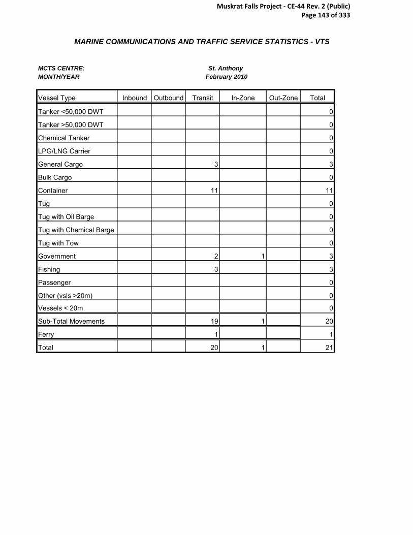
MARINE COMMUNICATIONS AND TRAFFIC SERVICE STATISTICS - VTS
MCTS CENTRE:MONTH/YEAR
Vessel Type Inbound Outbound Transit In-Zone Out-Zone Total
Tanker <50,000 DWT 0
Tanker >50,000 DWT 0
Chemical Tanker 0
LPG/LNG Carrier 0
General Cargo 3 3
Bulk Cargo 0
Container 11 11
Tug 0
Tug with Oil Barge 0
Tug with Chemical Barge 0
Tug with Tow 0
Government 2 1 3
Fishing 3 3
Passenger 0
Other (vsls >20m) 0
Vessels < 20m 0
Sub-Total Movements 19 1 20
Ferry 1 1
Total 20 1 21
St. Anthony February 2010
Muskrat Falls Project - CE-44 Rev. 2 (Public) Page 143 of 333
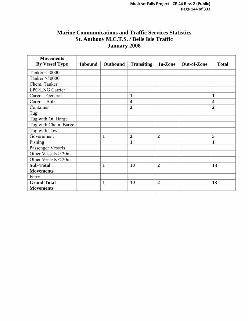
Marine Communications and Traffic Services Statistics St. Anthony M.C.T.S. / Belle Isle Traffic
January 2008
Movements By Vessel Type Inbound Outbound Transiting In-Zone Out-of-Zone Total
Tanker <50000 Tanker >50000 Chem. Tanker LPG/LNG Carrier Cargo – General 1 1 Cargo – Bulk 4 4 Container 2 2 Tug Tug with Oil Barge Tug with Chem. Barge Tug with Tow Government 1 2 2 5 Fishing 1 1 Passenger Vessels Other Vessels > 20m Other Vessels < 20m Sub-Total Movements
1 10 2 13
Ferry Grand Total Movements
1 10 2 13
Muskrat Falls Project - CE-44 Rev. 2 (Public) Page 144 of 333

MARINE COMMUNICATIONS AND TRAFFIC SERVICE STATISTICS - VTS
MCTS CENTRE:MONTH/YEAR
Vessel Type Inbound Outbound Transit In-Zone Out-Zone Total
Tanker <50,000 DWT 6 6
Tanker >50,000 DWT 1 1
Chemical Tanker 0
LPG/LNG Carrier 0
General Cargo 11 11
Bulk Cargo 12 12
Container 1 1 13 15
Tug 0
Tug with Oil Barge 0
Tug with Chemical Barge 0
Tug with Tow 5 5
Government 1 2 3
Fishing 5 5
Passenger 0
Other (vsls >20m) 1 1 2
Vessels < 20m 0
Sub-Total Movements 3 1 56 0 0 60
Ferry 1
Total 3 1 56 0 1 60
St. AnthonyJanuary 2009
Muskrat Falls Project - CE-44 Rev. 2 (Public) Page 145 of 333

MARINE COMMUNICATIONS AND TRAFFIC SERVICE STATISTICS - VTS
MCTS CENTRE:MONTH/YEAR
Vessel Type Inbound Outbound Transit In-Zone Out-Zone Total
Tanker <50,000 DWT 5 5
Tanker >50,000 DWT 0
Chemical Tanker 0
LPG/LNG Carrier 0
General Cargo 2 2
Bulk Cargo 16 16
Container 20 20
Tug 0
Tug with Oil Barge 0
Tug with Chemical Barge 0
Tug with Tow 0
Government 1 1
Fishing 2 2
Passenger 0
Other (vsls >20m) 0
Vessels < 20m 0
Sub-Total Movements 46 46
Ferry 1 1
Total 47 47
St. AnthonyJanuary 2010
Muskrat Falls Project - CE-44 Rev. 2 (Public) Page 146 of 333

MARINE COMMUNICATIONS AND TRAFFIC SERVICE STATISTICS - VTS
MCTS CENTRE:MONTH/YEAR
Vessel Type Inbound Outbound Transit In-Zone Out-Zone Total
Tanker <50,000 DWT 13 13
Tanker >50,000 DWT 0
Chemical Tanker 0
LPG/LNG Carrier 0
General Cargo 29 29
Bulk Cargo 27 27
Container 12 12
Tug 0
Tug with Oil Barge 0
Tug with Chemical Barge 0
Tug with Tow 6 6
Government 1 1 3 5
Fishing 4 4
Passenger 2 1 3
Other (vsls >20m) 1 1 2
Vessels < 20m 0
Sub-Total Movements 2 1 97 1 0 101
Ferry
Total 2 1 97 1 0 101
St. AnthonyJuly 2008
Muskrat Falls Project - CE-44 Rev. 2 (Public) Page 147 of 333

MARINE COMMUNICATIONS & TRAFFIC SERVICES STATISTICS - MCTS
HIGH LEVEL MCTS Centre: St. Anthony
Month / Year: July-2009
MOVEMENTSBY VESSEL TYPE INBOUND OUTBOUND TRANSITING IN-ZONE OUT-OF-ZONE TOTAL
Tanker < 50000 DWT 0 0 9 0 0 9
Tanker > 50000 DWT 0 0 2 0 0 2
Chemical Tanker 0 0 1 0 0 1
LPG/LNG Carrier 0 0 0 0 0 0
Cargo - General 0 0 11 0 0 11
Cargo - Bulk 0 0 19 0 0 19
Container 0 0 5 0 0 5
Tug 0 0 3 0 0 3
Tug with oil barge 0 0 0 0 0 0
Tug with chemical barge 0 0 0 0 0 0
Tug with Tow 0 0 4 0 0 4
Government 0 1 5 1 0 7
Fishing 0 0 4 0 0 4
Passenger Vessels 1 1 2 0 0 4
Other Vessels > 20 m 0 0 3 0 0 3
Other Vessels < 20 m 0 0 0 0 0 0
Sub-Total Movements 1 2 68 1 0 72
Ferry 0 0 0 0 0 0
Grand Total Movements 1 2 68 1 0 72
Muskrat Falls Project - CE-44 Rev. 2 (Public) Page 148 of 333

MARINE COMMUNICATIONS AND TRAFFIC SERVICE STATISTICS - VTS
MCTS CENTRE:MONTH/YEAR
Vessel Type Inbound Outbound Transit In-Zone Out-Zone Total
Tanker <50,000 DWT 9 9
Tanker >50,000 DWT 0
Chemical Tanker 0
LPG/LNG Carrier 0
General Cargo 15 15
Bulk Cargo 22 22
Container 13 13
Tug 0
Tug with Oil Barge 0
Tug with Chemical Barge 0
Tug with Tow 1 1
Government 1 6 7
Fishing 7 7
Passenger 2 3 1 6
Other (vsls >20m) 0
Vessels < 20m 0
Sub-Total Movements 2 4 73 1 0 80
Ferry
Total 2 4 73 1 0 80
Participating Vessels 2.67 Defects/Deficiencies
Clearances Requested Pollution Reports Land/Sea
Reports to OGDs Contraventions(Infringements/Violations)
PPO Instructions Traffic Recommendations
Traffic Directions
St. AnthonyJune 2008
Muskrat Falls Project - CE-44 Rev. 2 (Public) Page 149 of 333

MARINE COMMUNICATIONS & TRAFFIC SERVICES STATISTICS - MCTS
HIGH LEVEL MCTS Centre: St. Anthony
Month / Year: June-2009
MOVEMENTSBY VESSEL TYPE INBOUND OUTBOUND TRANSITING IN-ZONE OUT-OF-ZONE TOTAL
Tanker < 50000 DWT 0 0 5 0 0 5
Tanker > 50000 DWT 0 0 0 0 0 0
Chemical Tanker 0 0 0 0 0 0
LPG/LNG Carrier 0 0 0 0 0 0
Cargo - General 0 0 6 0 0 6
Cargo - Bulk 0 0 7 0 0 7
Container 0 0 1 0 0 1
Tug 0 0 1 0 0 1
Tug with oil barge 0 0 0 0 0 0
Tug with chemical barge 0 0 0 0 0 0
Tug with Tow 0 0 1 0 0 1
Government 1 2 2 1 0 6
Fishing 0 0 5 0 0 5
Passenger Vessels 0 0 0 0 0 0
Other Vessels > 20 m 0 0 0 0 0 0
Other Vessels < 20 m 0 0 0 0 0 0
Sub-Total Movements 1 2 28 1 0 32
Ferry 0 0 0 0 0 0
Grand Total Movements 1 2 28 1 0 32
Muskrat Falls Project - CE-44 Rev. 2 (Public) Page 150 of 333

Marine Communications and Traffic Services Statistics St. Anthony M.C.T.S. / Belle Isle Traffic
March 2008
Movements By Vessel Type Inbound Outbound Transiting In-Zone Out-of-Zone Total
Tanker <50000 Tanker >50000 Chem. Tanker LPG/LNG Carrier Cargo – General Cargo – Bulk 3 3
Container Tug Tug with Oil Barge Tug with Chem. Barge Tug with Tow Government Fishing Passenger Vessels Other Vessels > 20m Other Vessels < 20m Sub-Total Movements
3 3
Ferry Grand Total Movements
3 3
Muskrat Falls Project - CE-44 Rev. 2 (Public) Page 151 of 333
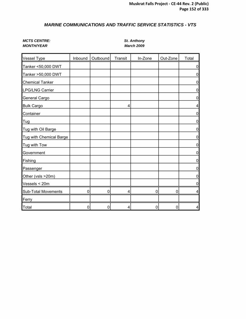
MARINE COMMUNICATIONS AND TRAFFIC SERVICE STATISTICS - VTS
MCTS CENTRE:MONTH/YEAR
Vessel Type Inbound Outbound Transit In-Zone Out-Zone Total
Tanker <50,000 DWT 0
Tanker >50,000 DWT 0
Chemical Tanker 0
LPG/LNG Carrier 0
General Cargo 0
Bulk Cargo 4 4
Container 0
Tug 0
Tug with Oil Barge 0
Tug with Chemical Barge 0
Tug with Tow 0
Government 0
Fishing 0
Passenger 0
Other (vsls >20m) 0
Vessels < 20m 0
Sub-Total Movements 0 0 4 0 0 4
Ferry
Total 0 0 4 0 0 4
St. AnthonyMarch 2009
Muskrat Falls Project - CE-44 Rev. 2 (Public) Page 152 of 333

MARINE COMMUNICATIONS AND TRAFFIC SERVICE STATISTICS - VTS
MCTS CENTRE:MONTH/YEAR
Vessel Type Inbound Outbound Transit In-Zone Out-Zone Total
Tanker <50,000 DWT 0
Tanker >50,000 DWT 0
Chemical Tanker 0
LPG/LNG Carrier 0
General Cargo 1 1
Bulk Cargo 5 5
Container 14 14
Tug 0
Tug with Oil Barge 0
Tug with Chemical Barge 0
Tug with Tow 0
Government 1 1 3 4 9
Fishing 4 4
Passenger 0
Other (vsls >20m) 0
Vessels < 20m 0
Sub-Total Movements 1 1 27 4 33
Ferry
Total 1 1 27 4 33
St. AnthonyMarch 2010
Muskrat Falls Project - CE-44 Rev. 2 (Public) Page 153 of 333

MARINE COMMUNICATIONS AND TRAFFIC SERVICE STATISTICS - VTS
MCTS CENTRE:MONTH/YEAR
Vessel Type Inbound Outbound Transit In-Zone Out-Zone Total
Tanker <50,000 DWT 2 1 7 10
Tanker >50,000 DWT 0
Chemical Tanker 0
LPG/LNG Carrier 0
General Cargo 5 5
Bulk Cargo 6 6
Container 0
Tug 0
Tug with Oil Barge 0
Tug with Chemical Barge 0
Tug with Tow 0
Government 4 4
Fishing 4 4
Passenger 0
Other (vsls >20m) 0
Vessels < 20m 0
Sub-Total Movements 2 1 26 0 0 29
Ferry
Total 2 1 26 0 0 29
St. AnthonyMay 2008
Muskrat Falls Project - CE-44 Rev. 2 (Public) Page 154 of 333

MARINE COMMUNICATIONS AND TRAFFIC SERVICE STATISTICS - VTS
MCTS CENTRE:MONTH/YEAR
Vessel Type Inbound Outbound Transit In-Zone Out-Zone Total
Tanker <50,000 DWT 2 2 4
Tanker >50,000 DWT 0
Chemical Tanker 0
LPG/LNG Carrier 0
General Cargo 0
Bulk Cargo 1 1
Container 0
Tug 0
Tug with Oil Barge 0
Tug with Chemical Barge 0
Tug with Tow 0
Government 2 2
Fishing 1 1
Passenger 0
Other (vsls >20m) 0
Vessels < 20m 0
Sub-Total Movements 0 0 4 4 0 8
Ferry
Total 0 0 4 4 0 8
St. AnthonyMay 2009
Muskrat Falls Project - CE-44 Rev. 2 (Public) Page 155 of 333

MARINE COMMUNICATIONS AND TRAFFIC SERVICE STATISTICS - VTS
MCTS CENTRE:MONTH/YEAR
Vessel Type Inbound Outbound Transit In-Zone Out-Zone Total
Tanker <50,000 DWT 1 1 13 4 19
Tanker >50,000 DWT 0
Chemical Tanker 0
LPG/LNG Carrier 0
General Cargo 18 18
Bulk Cargo 1 35 36
Container 34 34
Tug 1 1
Tug with Oil Barge 0
Tug with Chemical Barge 0
Tug with Tow 3 3
Government 1 3 1 5
Fishing 2 2
Passenger 0
Other (vsls >20m) 0
Vessels < 20m 1 1
Sub-Total Movements 1 3 110 5 0 119
Ferry
Total 1 3 110 5 0 119
St. AnthonyNovember 2008
Muskrat Falls Project - CE-44 Rev. 2 (Public) Page 156 of 333

MARINE COMMUNICATIONS AND TRAFFIC SERVICE STATISTICS - VTS
MCTS CENTRE:MONTH/YEAR
Vessel Type Inbound Outbound Transit In-Zone Out-Zone Total
Tanker <50,000 DWT 1 1 15 17
Tanker >50,000 DWT
Chemical Tanker
LPG/LNG Carrier
General Cargo 12 12
Bulk Cargo 1 1 44 46
Container 31 31
Tug
Tug with Oil Barge
Tug with Chemical Barge
Tug with Tow 5 5
Government 1 1
Fishing 4 4
Passenger 0
Other (vsls >20m) 1 1
Vessels < 20m 0
Sub-Total Movements 2 2 113 0 0 117
Ferry
Total 2 2 113 0 0 117
St. AnthonyNovember 2009
Muskrat Falls Project - CE-44 Rev. 2 (Public) Page 157 of 333

MARINE COMMUNICATIONS AND TRAFFIC SERVICE STATISTICS - VTS
MCTS CENTRE:MONTH/YEAR
Vessel Type Inbound Outbound Transit In-Zone Out-Zone Total
Tanker <50,000 DWT 13 13
Tanker >50,000 DWT 0
Chemical Tanker 0
LPG/LNG Carrier 0
General Cargo 25 25
Bulk Cargo 36 36
Container 37 37
Tug 4 4
Tug with Oil Barge 0
Tug with Chemical Barge 0
Tug with Tow 3 3
Government 1 1 5 1 8
Fishing 2 2
Passenger 1 2 3
Other (vsls >20m) 0
Vessels < 20m 0
Sub-Total Movements 2 3 125 1 0 131
Ferry
Total 2 3 125 1 0 131
St. AnthonyOctober 2008
Muskrat Falls Project - CE-44 Rev. 2 (Public) Page 158 of 333

MARINE COMMUNICATIONS AND TRAFFIC SERVICE STATISTICS - VTS
MCTS CENTRE:MONTH/YEAR
Vessel Type Inbound Outbound Transit In-Zone Out-Zone Total
Tanker <50,000 DWT 20 20
Tanker >50,000 DWT
Chemical Tanker
LPG/LNG Carrier
General Cargo 22 22
Bulk Cargo 29 0
Container 22 22
Tug 1 1
Tug with Oil Barge
Tug with Chemical Barge
Tug with Tow 1 6 2 9
Government 2
Fishing 7 7
Passenger 1 1 2 4
Other (vsls >20m) 1 1
Vessels < 20m 0
Sub-Total Movements 1 3 111 2 0 117
Ferry
Total 1 3 111 2 0 117
St. AnthonyOctober 2009
Muskrat Falls Project - CE-44 Rev. 2 (Public) Page 159 of 333

MARINE COMMUNICATIONS AND TRAFFIC SERVICE STATISTICS - VTS
MCTS CENTRE:MONTH/YEAR
Vessel Type Inbound Outbound Transit In-Zone Out-Zone Total
Tanker <50,000 DWT 2 2 12 1 17
Tanker >50,000 DWT 0
Chemical Tanker 0
LPG/LNG Carrier 0
General Cargo 26 26
Bulk Cargo 32 32
Container 44 44
Tug 1 1
Tug with Oil Barge 0
Tug with Chemical Barge 0
Tug with Tow 2 2
Government 2 1 3 1 7
Fishing 1 8 9
Passenger 1 4 1 6
Other (vsls >20m) 1 1
Vessels < 20m 0
Sub-Total Movements 4 5 133 3 0 145
Ferry
Total 4 5 133 3 0 145
St. AnthonySeptember 2008
Muskrat Falls Project - CE-44 Rev. 2 (Public) Page 160 of 333
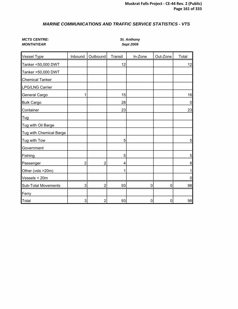
MARINE COMMUNICATIONS AND TRAFFIC SERVICE STATISTICS - VTS
MCTS CENTRE:MONTH/YEAR
Vessel Type Inbound Outbound Transit In-Zone Out-Zone Total
Tanker <50,000 DWT 12 12
Tanker >50,000 DWT
Chemical Tanker
LPG/LNG Carrier
General Cargo 1 15 16
Bulk Cargo 28 0
Container 23 23
Tug
Tug with Oil Barge
Tug with Chemical Barge
Tug with Tow 5 5
Government
Fishing 5 5
Passenger 2 2 4 8
Other (vsls >20m) 1 1
Vessels < 20m 0
Sub-Total Movements 3 2 93 0 0 98
Ferry
Total 3 2 93 0 0 98
St. AnthonySept 2009
Muskrat Falls Project - CE-44 Rev. 2 (Public) Page 161 of 333

Appendix L- Fishing Gear
Muskrat Falls Project - CE-44 Rev. 2 (Public) Page 162 of 333

Appendix M- HDD Feasibility Report
Muskrat Falls Project - CE-44 Rev. 2 (Public) Page 163 of 333

Appendix N- RT-1 and Assotrencher IV
Muskrat Falls Project - CE-44 Rev. 2 (Public) Page 164 of 333
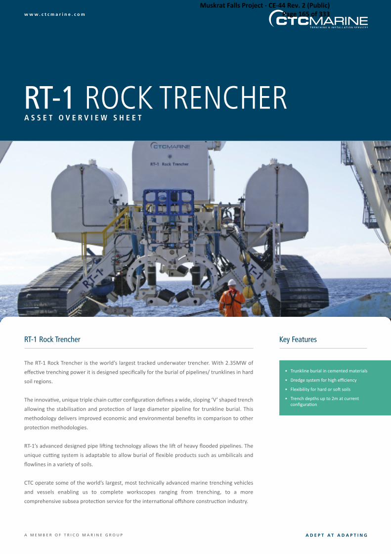
w w w . c t c m a r i n e . c o m
A D E P T A T A D A P T I N GA M E M B E R O F T R I C O M A R I N E G R O U P
A S S E T O V E R V I E W S H E E T
RT-1 Rock Trencher Key Features
RT-1 ROCK TRENCHER
The RT-1 Rock Trencher is the world’s largest tracked underwater trencher. With 2.35MW of
effec+ve trenching power it is designed specifically for the burial of pipelines/ trunklines in hard
soil regions.
The innova+ve, unique triple chain cu,er configura+on defines a wide, sloping ‘V’ shaped trench
allowing the stabilisa+on and protec+on of large diameter pipeline for trunkline burial. This
methodology delivers improved economic and environmental benefits in comparison to other
protec+on methodologies.
RT-1’s advanced designed pipe li�ing technology allows the li� of heavy flooded pipelines. The
unique cu-ng system is adaptable to allow burial of flexible products such as umbilicals and
flowlines in a variety of soils.
CTC operate some of the world’s largest, most technically advanced marine trenching vehicles
and vessels enabling us to complete workscopes ranging from trenching, to a more
comprehensive subsea protec+on service for the interna+onal offshore construc+on industry.
• Trunkline burial in cemented materials
• Dredge system for high efficiency
• Flexibility for hard or so� soils
• Trench depths up to 2m at currentconfigura+on
Muskrat Falls Project - CE-44 Rev. 2 (Public) Page 165 of 333

w w w . c t c m a r i n e . c o mA M E M B E R O F T R I C O M A R I N E G R O U P
A S S E T O V E R V I E W S H E E T
Head OfficeConiscliffe House, Coniscliffe Road,Darlington, DL3 7EE, EnglandT | (+44) 0 1325 390 500F | (+44) 0 1325 390 555E | [email protected]
Singapore Office15 Changi South St1,Singapore, 486783T | (+65) 6329 9642F | (+65) 6543 3416E | [email protected]
Perth OfficeLevel 2, 33 Barrack Street,Perth, 6000, Western AustraliaT | (+61) 8 9218 8400E | [email protected]
Aberdeen OfficeThe Enterprise Centre,Exploration Drive,Bridge of Don, Aberdeen,AB23 8GX, ScotlandT | (+44) 0 1224 355 440
Dubai OfficeP.O. Box 54455, Office No. 5WA 228,West Wing Building #5A,Dubai Airport Free Zone,Dubai U.A.ET | (+971) 4 299 3677F | (+971) 4 299 3946
CTC Marine Projects Ltd. accepts no responsibility for and disclaims all liability for any errors and/or omissions in this publication. SPECIFICATION SUBJECT TO CHANGE WITHOUT NOTICE.
The RT-1 Rock Trencher is not limited to these parameters and can be modifiedby CTC to complete workscopes in excess of its current configuration.
REV01/LH
GENERAL
Opera+ng Depth 500m
Maximum Trench Depth 2m
Trench Profile ‘V’ Trench – 45 degree wall
Pipe Size1500mm O.D maximum clearance (includesallowance for anodes, joints and piggy-back line)
Pipe Following TSS440 pipe tracker, OA sonar and cameras
DIMENSIONS
Length 22.5m
Width 13m
Height 9.6m
Weight in Air 202te
PIPE HANDLING
Configura+on 2 cradles
Pipe Load 65te maximum per cradle
Pipe Size1500mm O.D lateral clearance1500mm O.D ver+cal clearance
Roller Configura+on 2 sets of triple rollers per cradle
SOIL TYPESSuitable for a range of sands, clays and rock
CHAIN CUTTER SYSTEM
Configura+onThree individually powered and posi+oned cu,erchains, set at 45 degrees
Pipe LoadChain 1 – 250kWChain 2 – 400kWChain 3 – 400kW
Pipe Size Heavy duty interleaved chain
Roller Configura+onChain 1 - variable to 2.4m/sChain 2 - variable up to 3.2m/sChain 3 - variable up to 3.2m/s
Cu,er Width 800mm
DREDGE AND JETTING SYSTEM
Configura+on
Four hydraulically driven dredge pumps. Two midmounted units to remove spoil excavated in frontof the main chain cu,ers. Two rear mountedunits for clearing re-circulated spoil from thechain cu,ers and any premature backfill fromso� overburden collapse
Pumps4 x 80kW heavy duty dredge pumps.Opera+ng point approximately1500m3/hr @ 0.75 bar
Main Je-ng System
2 x 350kW direct coupled motor/ pump sets –approximately 2400m3/hr @ 7 bar. Supplies rearjet legs, dredge heads, cu,er chain cleaningand HPU cooling as required
Muskrat Falls Project - CE-44 Rev. 2 (Public) Page 166 of 333

Assotrencher IV, built for the purpose of executing burial
works in soils and conditions where three factors co exist;
Very hard soils, Uneven territories and little or no slack
given to the cables. Its unique design and method of
operation, enables the loading and securing of heavy cables
on the vehicle, without reducing its’ ability to maneuver or
perform effectively the trenching operation.
Although its’ long dimensions, Assotrencher IV is able to
maneuver effectively in rough territories and to withstand
the extraordinary shear forces and tensions resulting from
trenching in areas full of rocks and boulders.
Assotrencher IV, as the entire "Assotrencher" family
vehicle, uses high end technology to show the operator and
record all crucial information necessary to accumulate the
condition of the vehicle and the cable. Crucial data are
recorded in real-time, including images from cameras and
profiling and scanning sonars.
Muskrat Falls Project - CE-44 Rev. 2 (Public) Page 167 of 333

MAIN DATA Length: 6.5 m Breadth: 3.9 m Height: 3.5 m Weight: 25,000 kg Depth rating: 200m TOOL OPTIONS Cutting Wheel (1) Used in hard soils (rock, hard clay) Diameter: 2.0 m Weight: 2,500 kg Cutting Wheel (2) Used in hard soils (rock, hard clay) Diameter: 2.5 m Weight: 6,500 kg Rocksaw Used in mix soils (gravel, stones) Length: 4.9 m Weight: 5,000 kg CABLE LOADING SYSTEM A system of four (4) remote operated grabbers is fitted onto the vehicle for loading the underwater cables to be protected. This system is diver less and utilized these specially made grabbers installed on the lower part of the vehicle, for bottom – loading power cables that have little slack available. UMBILICAL Consisting of multiple Medium Voltage Lines for powering the vehicle and single mode fibers for the communication purposes. Extra simple power lines are also installed for backup purposes, in case of failure of the primary communication lines. POWER STATION A container fitted with the necessary medium voltage fields and the necessary safety measures for the powering of the vehicle is used and installed nearby the generating sets. This container is remotely controlled and monitored from the control room container.
CONTROL ROOM The control system of the vehicle is installed inside a air conditioned 20ft container with large windows for monitoring the launch and recovering activities on deck. Inside this control room all the necessary controls, monitors (video and VGA), recording devices and powering arrangements are installed, while uplink outputs are available for the connection of the control room to the remote viewing stations on the support vessel. Monitoring of the vehicle and recording is done from PC-based software with graphic user-friendly display. Back-up systems are also installed for handling emergency situations. SENSOR EQUIPMENT
• Simrad/Mesotech scanning sonar • Simrad/Mesotech profiling sonar • 8 low light underwater cameras • 2 Pan-Tilt camera modules • Simrad Transponder/Responder • Compass/Attitude sensors • 6 Underwater lights • Pressure monitoring system • TSS 350 Cable Tracker (option) • Onboard small inspection ROV (option)
.
34 Charilaou Trikoupi st. • Piraues • GR 18536, Greece, Tel: +30 210 4527050 Fax: +30 210 4527053
[email protected] • www.assodivers.gr
Muskrat Falls Project - CE-44 Rev. 2 (Public) Page 168 of 333

Appendix O- Shore Based Tunnel to Seabed Techniques
Muskrat Falls Project - CE-44 Rev. 2 (Public) Page 169 of 333

ADDR.: Statnett SF Projects/Cable Technology Hoffsveien 70B, 0377 Oslo PO Box 5192 Majorstuen N-0302 OSLO, NORWAY
Document title
SOBI Cable Crossing
Shore based tunnel to seabed techniques Immediate comments
Classification
Confidential Project No. IFS 55247
Responsible department BK
Document No. 1456707
Pages + attachments 8
Client Nalcor Energy
Client reference
WTO DC1401 Order No.
LC-PM-007
Summary, result:
The Lower Churchill Project is in the process of comparing the tunnel crossing option and the submarine cable option for the HVDC cable crossing of the Strait of Belles Isles. This preliminary report is giving immediate answers to details regarding tunnel to seabed techniques. A final report will be issued shortly. It seems to be a sufficient experience base for thinking that a safe shore approach consisting of a combination of tunnel and drilled holes can be constructed, even if the tunnel ends far below the water surface. Distribution
Rev Date Description Author Checked Approved
2 2A 1
2010-09-10
Issued for client review
TL/GJ/JES
KRø
JES
This document is issued by means of a computerized system. The digitally stored original is electronically approved. The approved document has a name entered in the approved-field. A manual signature is not required
Muskrat Falls Project - CE-44 Rev. 2 (Public) Page 170 of 333

SOBI Cable Crossing
Shore based tunnel to seabed techniques, Immediate comments
Rev.: Date: Page:
1 2010-09-10
2 of 8
Doc-id: 1456707
CONTENTS
1 INTRODUCTION......................................................................................................3
2 BACKGROUND.......................................................................................................3
3 ALTERNATIVE SHORE APPROACH METHODS...................................................3
3.1 Examples .................................................................................................................4
3.2 NorNed and Troll Cable shore approaches ..............................................................6
3.3 Miscellaneous ..........................................................................................................7
3.4 Tunnel and sealing details........................................................................................8
3.5 Pull-in and installation of cable .................................................................................8
4 SHORE APPOACH LABRADOR ............................................................................8
5 SHORE APPROACH NEWFOUNDLAND ...............................................................8
Muskrat Falls Project - CE-44 Rev. 2 (Public) Page 171 of 333
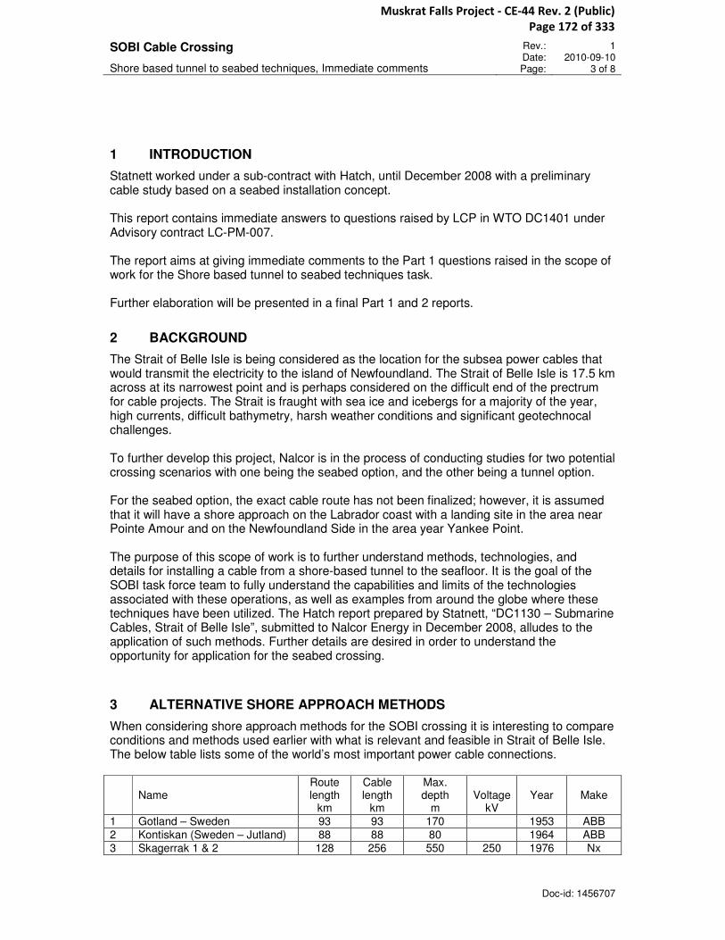
SOBI Cable Crossing
Shore based tunnel to seabed techniques, Immediate comments
Rev.: Date: Page:
1 2010-09-10
3 of 8
Doc-id: 1456707
1 INTRODUCTION
Statnett worked under a sub-contract with Hatch, until December 2008 with a preliminary cable study based on a seabed installation concept. This report contains immediate answers to questions raised by LCP in WTO DC1401 under Advisory contract LC-PM-007. The report aims at giving immediate comments to the Part 1 questions raised in the scope of work for the Shore based tunnel to seabed techniques task. Further elaboration will be presented in a final Part 1 and 2 reports.
2 BACKGROUND
The Strait of Belle Isle is being considered as the location for the subsea power cables that would transmit the electricity to the island of Newfoundland. The Strait of Belle Isle is 17.5 km across at its narrowest point and is perhaps considered on the difficult end of the prectrum for cable projects. The Strait is fraught with sea ice and icebergs for a majority of the year, high currents, difficult bathymetry, harsh weather conditions and significant geotechnocal challenges. To further develop this project, Nalcor is in the process of conducting studies for two potential crossing scenarios with one being the seabed option, and the other being a tunnel option. For the seabed option, the exact cable route has not been finalized; however, it is assumed that it will have a shore approach on the Labrador coast with a landing site in the area near Pointe Amour and on the Newfoundland Side in the area year Yankee Point. The purpose of this scope of work is to further understand methods, technologies, and details for installing a cable from a shore-based tunnel to the seafloor. It is the goal of the SOBI task force team to fully understand the capabilities and limits of the technologies associated with these operations, as well as examples from around the globe where these techniques have been utilized. The Hatch report prepared by Statnett, “DC1130 – Submarine Cables, Strait of Belle Isle”, submitted to Nalcor Energy in December 2008, alludes to the application of such methods. Further details are desired in order to understand the opportunity for application for the seabed crossing.
3 ALTERNATIVE SHORE APPROACH METHODS
When considering shore approach methods for the SOBI crossing it is interesting to compare conditions and methods used earlier with what is relevant and feasible in Strait of Belle Isle. The below table lists some of the world’s most important power cable connections.
Name Route length
km
Cable length
km
Max. depth
m
Voltage
kV
Year
Make
1 Gotland – Sweden 93 93 170 1953 ABB
2 Kontiskan (Sweden – Jutland) 88 88 80 1964 ABB
3 Skagerrak 1 & 2 128 256 550 250 1976 Nx
Muskrat Falls Project - CE-44 Rev. 2 (Public) Page 172 of 333
SOBI Cable Crossing
Shore based tunnel to seabed techniques, Immediate comments
Rev.: Date: Page:
1 2010-09-10
4 of 8
Doc-id: 1456707
4 Italy– Corsica – Sardinia 119 238 500 200 1965 P
5 Fenno Skan 1 (Sweden–Finland)
200 200 120 1989 ABB/Nx
6 Basslink (Victoria – Tasmania) 295 295 200 400 2006 P
7 SwePol (Sweden – Poland) 250 250 80 450 2000 ABB
8 Italy – Greece 163 163 1000 2000 P
9 NorNed (Norway – Netherlands)
580 1160 410 450 2007 ABB/Nx
10 Italy – Corsica – Sardinia 120 - 500 - D P/Nx
11 Spain – Mallorca ca 180 - 900-1800 - D P/Nx
12 Fenno Skan 2 200 200 120 500 2011 Nx
13 Spain – Morocco (SCFF) 25 175 615 420 1995 Nx/P
14 Gulf of Aqaba (SCFF) 15 60 800 420 1998 Nx
ABB – ABB High Voltage Cables Nx – Nexans Norway
P – Prysmian D – Project under development
It is an obvious fact that none of the existing connections is directly comparable to the planned SOBI crossing. The combination of the relatively shallow and very rocky conditions combined with severe ice conditions both in terms of drifting winter ice as well as icebergs drifting through the strait, makes the shore approach challenges new and special. This is why the solution applied in the NorNed case has inspired the method described in the feasibility report issued by Hatch with Statnett as subcontractor. This method will be given immediate comments in this report while the comparison with other installations will be further developed in the complete report to be issued later.
3.1 Examples
It is perhaps five categories of cable installation methods which might be of interest for the SOBI crossing: The a.“NorNed method”, b.directional drilled installations, c.pre-installed pipes ,d.J-tubes and e.subsea tunnel with vertical riser shaft. a. The NorNed method is shown on the drawing below. It is the only of its kind.
Figure1 The NorNed tunnel and drill hole cable installation
Muskrat Falls Project - CE-44 Rev. 2 (Public) Page 173 of 333
SOBI Cable Crossing
Shore based tunnel to seabed techniques, Immediate comments
Rev.: Date: Page:
1 2010-09-10
5 of 8
Doc-id: 1456707
A large tunnel 25 m2 with 12% steepness is leading from the converter station and down to a jointing chamber approximately 5m above highest water level. To the jointing chamber the submarine cables were pulled in through 300 mm drilled rock holes lined with thick walled polyethylene pipes. Basically the same concept has been presumed in the Statnett/ Hatch report, the main difference being that the drilled holes will have to be directed horizontally or probably upwards and would need to penetrate towards e.g. 7 bar water pressure. Exactly this method has not been applied for a large power cable before. However, at Kallsto west of Haugesund a similar method was used for a gas pipeline and for a control cable. This will be further described in the final report. b. Directional drilled installations Pulling of all sorts of cable through drilled, lined holes has become quite common in cable connections for example in motor road crossings, river crossings, etc. The longest pulling known to us so far with cable of a relevant weight is 500m. The safe length will depend on the friction and of number and character of the bends and whether horizontal or vertical. c. Pre-installed pipes Solid shore approach protection can be achieved by pre-installing steel pipes or polyethylene pipes. The pipes can be put into blasted or excavated trenches and be anchored and protected by concreting, rock dump, sandbagging or other. This method was used in Osundet in the first power from shore project to Troll A platform. The large cable was pulled through approximately 50 m thick walled polyethylene pipes from 5 m water depth and up to a jointing pit. Another example known to us is a river crossing in Tinn river close to Notodden in Norway. To protect and anchor the three single core cables in the strong river current three polyethylene pipes were laid in a pre made trench and special concrete was used for under water concreting of the trench backfill. d. J-tubes When bringing cables (as well as umbilicals) from sea floor and up to the topside of an offshore platform J-tubes of steel is being used. The experience with pulling of cables and sealing at the entrance and on the top of these J-tubes is relevant when trying to find good safe methods for SOBI shore approaches. World wide it is a large number of this type of installation. e. Subsea tunnel with vertical riser shaft The perhaps most important example is the Troll A pipeline to shore approach. Two 1 m diameter, two flow pipelines was to be installed from 350 m water depth and to shore over a relatively short distance and through very uneven, rocky seabed.
Muskrat Falls Project - CE-44 Rev. 2 (Public) Page 174 of 333

SOBI Cable Crossing
Shore based tunnel to seabed techniques, Immediate comments
Rev.: Date: Page:
1 2010-09-10
6 of 8
Doc-id: 1456707
It was decided to let the last 3.6 km towards shore be installed in a subsea tunnel. The connection to the seabed was made by blasting a vertical shaft.
3.2 NorNed and Troll Cable shore approaches
As already explained NorNed utilises a combination of tunnel and drilled holes. The very steep, rocky shore made this solution simple to apply since the bore hole reached 50 m water depth with a length of 150 m only. The tunnel as such and the way the cable is installed is relevant and applicable for SOBI shore approach tunnels. However, the fact that the tunnel will end a considerable number of metres below the water surface creates many additional challenges. When the 70 km 52 kV AC cable from shore to the Troll A gas platform was to be engineered in 1993 it was carefully considered if the power cable should utilise the same shore approach as the two large pipelines. The concept for that shore approach is shown as an artist’s impression in figure 2 below.
Figure 2 – The Troll gas pipeline shore approach tunnel system The principle used is the same as developed for hydro power schemes built inside mountains. When the headrace tunnel reaches the intake dam the piercing is normally done by means of a vertical shaft and the last remaining metres blasted under water letting the blasted rock fall down into the tunnel. The pipeline transition from seafloor to tunnel was arranged as a vertical riser with pre-installed bends in the “hat” which was mounted at the top of the vertical shaft. The subsea tie in was done as usual.
Muskrat Falls Project - CE-44 Rev. 2 (Public) Page 175 of 333

SOBI Cable Crossing
Shore based tunnel to seabed techniques, Immediate comments
Rev.: Date: Page:
1 2010-09-10
7 of 8
Doc-id: 1456707
A method for cable tie in was developed and cost estimated and a thorough comparison was done with a bit longer cable route but with a more normal shore approach. The latter was chosen for the following main reasons:
1. Lower cost 2. Risk related to prototype installation method 3. The very large tunnel was for safety reasons (gas) to be operated flooded and
it would take 2-3 months to empty and make the tunnel ready for a potential cable repair.
3.3 Miscellaneous
Tunnel gradient The 12% gradient has been recommended as that gradient makes both construction as well as later use of the tunnel practical based on ordinary truck driving. Cable jointing chamber The design of a rock cavern for jointing will be determined by usage aspects like initial and future number of cables, requirements for any safety or service facilities, the need for turning a truck. The jointing itself will take place in some sort of jointing house (in most cases part of the cable supplier delivery) inside the tunnel, normally with much smaller dimensions than the tunnel or the cavern. Sealing arrangement As can be understood from the examples described, there is up to now no direct reference for the potential SOBI case where it would be a need for sealing against ca 7 bar water pressure. However, based on the Kallsto experience and on engineering using a combination of previous, well established methods, we see clear possibility to basically maintain the proposed shore approach method. The intention is to describe this in more detail in the final report. Construction of micro tunnels There exist different drilling techniques for construction of micro tunnels. Examples will be described in the final report. Although we think that micro tunnelling can be used also when working against water pressure, it is reason to alternatively consider use of the vertical shaft method for the piercing. Drilling gradient Upwards drilling gradient is preferred because it is easier to get rid of the drill mud. It is, however, quite possible to drill downwards. This was done in the NorNed case. Micro tunnel diameter is determined by the cable pulling conditions. The rule of thumb is to try to achieve an inner diameter of the micro tunnel of 1.5 times the outer cable diameter. That could typically lead to a 200 mm requirement. With a thick-walled lining and some need for clearance for installation of the lining a 300 mm bore hole is in many cases practical. And this type of diameter can most often be achieved in one single drilling operation. Steel tube lining With micro tunnels in rock different types of lining can be used. In the NorNed case thick-walled polyethylene was used. However, when sealing against considerable water pressure is to be part of the system, steel lining is most likely a more practical solution. Details on steel lining installation Something more on this subject will be made part of the final report. It is, however, important to be aware that different contractors would have different preferences with respect to construction methods. In the rock hole case the lining
Muskrat Falls Project - CE-44 Rev. 2 (Public) Page 176 of 333

SOBI Cable Crossing
Shore based tunnel to seabed techniques, Immediate comments
Rev.: Date: Page:
1 2010-09-10
8 of 8
Doc-id: 1456707
will and can in most cases be installed after the drilling has been completed by pulling the full length into the hole in one continuous pulling operation. Drilling technology status As already stated this subject will be elaborated on in the final report. Achievable hole lengths Our understanding is that the present longest experienced micro tunnel drilling onshore is 750 m. More update on this later. Available contractors It is presently three-four Norwegian companies specialising in rock micro tunnelling. A broader picture to be established in the final report.
3.4 Tunnel and sealing details
Answers raised will be answered more completely in the final report. A large plug in the tunnel will rather be made by a combination of steel and concrete. The question regarding permanent or temporary pumping arrangement needs to be determined after having established an operational philosophy for the cable crossing. The system which will give the quickest access and readiness for inspections and a potential repair is of course to install permanent lighting and a pumping system. Anyway a pumping system during construction will most likely be necessary.
3.5 Pull-in and installation of cable
The main principle for the pull-in operation is to get the cable connected to a winch wire and get the cable pulled in in a controlled manner by subsea ROV monitoring and proper communication between the different operators on the cable ship and in the tunnel. At a depth of 70 m only this type of operation is a well established operation. The plan is to get this described and illustrated in the final report.
4 SHORE APPOACH LABRADOR
The character of the Labrador shore is different from the Newfoundland side. Relatively deep water is reached much faster. Before finally concluding that a subsea tunnel is needed, we suggest to review the conditions to see if the NorNed concept after all could be utilised on that side. If so, easier operations and lower cost would be achieved.
5 SHORE APPROACH NEWFOUNDLAND
Construction wise the Newfoundland side is the most challenging because of the shallow, very rocky shore. It might be that a shore approach tunnel will be the best solution in order to achieve an ice safe installation. It would easily be high cost and a difficult task to get sufficient cable protection all the way down to 70 m water depth. And such an operation is also very unpredictable.
Muskrat Falls Project - CE-44 Rev. 2 (Public) Page 177 of 333

Appendix P- Pro Dive Solutions
Muskrat Falls Project - CE-44 Rev. 2 (Public) Page 178 of 333
Subsea Mattress
FoundOcean
Pro-Dive Marine Services, in conjunction with FoundOcean, provides specialized geo-technical and structural services to the Canadian oil and gas industry. Focusing on installation, maintenance, repair and protection of platforms, templates and pipelines, a range of activities from feasibility studies through conceptual design, trials, procurement and construction to the provision of personnel and equipment for field operations are undertaken. In 1989 Pro-Dive Marine Services entered into an exclusive agreement with FoundOcean to provide the FoundOcean line of products to the Canadian marketplace. Subsequently, both companies have successfully undertaken various client-specific projects. Pro-Dive Marine Services and FoundOcean continually endeavor to comply with our client's specific requests. Emphasizing safety, quality products, and on time delivery, we can provide innovative low cost solutions to subsea related problems. Services Offered Pro-Dive Marine Services, in conjunction with FoundOcean, offers an extensive range of products and services, which include:
• Consultation, feasibility studies and systems related engineering
• Flexible concrete mattresses, precast units and ScourMat
• Grout mixing and pumping equipment
• Pipeline protection and stabilization
• Design and manufacture of fabric formworks
• Ballasting using viscous and heavy slurries
• Pipeline abandonment and plugging
• Inspection, repair and strengthening of offshore structures
The following subsections summarize the specialized offshore construction services offered by Pro-Dive Marine Services and FoundOcean. Flexible Concrete Mattresses and Pre-Cast Units
• Flexible pre-cast concrete mattresses are used for weight coating, support, stabilization and protection of pipelines and umbilicals. Lift frames are also available for subsea installation by diver, ROV, or top side deployment.
• Precast concrete units for crossings, ramps, supports and pipeline protection.
Muskrat Falls Project - CE-44 Rev. 2 (Public) Page 179 of 333
Massiv Mesh Massiv Mesh is a flexible, concrete mattress consisting of hexagonal concrete elements linked together with high strength non-degradable polypropylene rope. The mattresses have many uses in the protection, support and stabilization of subsea structures and have been designed for their flexibility and ease of handling during installation.
Flexiweight Flexiweight is a concrete mattress consisting of hexagonal section bars, reinforced with steel and linked by polypropylene rope. Flexiweight is flexible, robust, designed for ease of installation and available in a range of sizes and concrete densities. Flexiweight has an established track record for such
applications as Stabilization, Crossovers, Trawlboard, Cable protection and Scour prevention. ScourMat Tides and currents cause erosion of the seabed adjacent to solid objects known as scour. Scour affects the stability of pipelines and subsea structures and can also cause considerable damage to coastal areas. ScourMat is made from a series of polypropylene fronds attached to a polypropylene net and linked by a framing network of webbing that extends around the periphery and crosses the mat at regular intervals. A number of specially designed anchors are attached to the webbing. Underwater, the fronds open out to form a fan like array, which slows down the local current and causes particulate matter to settle. This eventually builds up a new sandbank, effectively reinstating the seabed. This fiber-reinforced sandbank will then resist further erosion. SeaMat SeaMat, a stabilization and protection system, based on bitumen-coated aggregates encased within a man-made woven fiber envelope, complete with integral lifting straps. Reinforcement is achieved by the use of a polypropylene Geogrid cage. SeaMat is designed to remedy the following subsea problems:
• Scour
• Crossover protection
• Impact damage
Provision of Mixing and Pumping Equipment Pro-Dive Marine Services, in conjunction with FoundOcean, has an extensive range of cement mixing and pumping equipment, for all types of offshore construction activities, available. The
Muskrat Falls Project - CE-44 Rev. 2 (Public) Page 180 of 333

equipment is capable of mixing very low water content (viscous and heavy) slurries. A wide selection of pump sets provides the optimum rate required for the best results. This equipment has been used for the following applications:
• Grouting activities associated with fabric formworks
• Platform construction pile grouting
• Perform repair and maintenance
• Template / structure ballasting
• Concrete structure repair and maintenance
• Pipeline plugging and well abandonment
Pro-Dive Marine Services has the total capacity and flexibility to work as a primary contractor in association with design engineers, operators and contractors, throughout the various phases of a project, from solution design through to the implementation of the project. Fabric Formwork Engineering fabric formwork offers a considerable range of possibilities to the offshore industry. In addition to the standard pipeline supports, specially designed fabric formwork is supplied for specific requirements, including:
• Mattresses for load distribution
• Pipeline crossings
• Riser supports
• Anti-scour systems
• Fabric seals for structural work in platforms
These varied systems have been used in water depths of 340 meters; deeper waters are within the scope of the plant. Subsea procedures are developed to ensure that the underwater contractor correctly applies the solutions. Attention to detail ensures that subsea time, whether for divers or ROV's is reduced, thus reducing the overall cost of the operation. Specialized Grouting Equipment Pro-Dive Marine Services and FoundOcean have acquired specially developed grouting equipment suitable to the wide range of work undertaken in the offshore environment. The well proven colloidal mixing principle gives excellent grout qualities suitable for underwater applications and has been adopted for all equipment. The main characteristics are:
• Compact skid mounted module units for restricted working space
• Established colloidal mixing system for underwater grouting
• Provision of pressurized bulk cement silos
• Ability to handle bagged materials (if required)
• A range of grouting outputs and injection pressures to suit application
• Facility to place grout at substantial underwater depths
In addition to fabric related applications Pro-Dive Marine Services and FoundOcean have the necessary expertise to undertake all aspects of offshore grouting including:
Muskrat Falls Project - CE-44 Rev. 2 (Public) Page 181 of 333

• Infilling of tubulars
• Annulus grouting
• Foundation underbase grouting
• Structural repairs
Muskrat Falls Project - CE-44 Rev. 2 (Public) Page 182 of 333

Appendix Q- COPS Report
Muskrat Falls Project - CE-44 Rev. 2 (Public) Page 183 of 333

COPS
Vehicle
Chapter n° XXX
Révision 2
DESCRIPTION
Date 07 / 2010
Page 1 / 7
COPSrev2 Ce document est la propriété de TRAVOCEAN il ne peut être reproduit ou communiqué sans notre autorisation ( loi 1902 )
1.0 Summary
1.1 Description
1.1.1 Vehicle
1.1.2 Frame
1.1.3 Track System
1.1.4 Thrusters
1.1.5 Hydraulic Power System
1.1.6 Process Table
1.2 Vehicle Performances
1.2.1 Ground Pressure
1.2.2 Speed
1.3 Instrumentation
1.3.1 Sector Scanning Sonar
1.3.2 Profillers
1.3.3 Compass
1.3.4 Cable Tracker
1.3.5 Other Sensors & Accessories
1.3.6 Control & Power Van
1.3.7 Umbilical Winch and Slip Ring
1.4 Drawings
1.4.1 Front view
1.4.2 Top view
1.4.3 Side view
Muskrat Falls Project - CE-44 Rev. 2 (Public) Page 184 of 333

COPS
Vehicle
Chapter n° XXX
Révision 2
DESCRIPTION
Date 07 / 2010
Page 2 / 7
COPSrev2 Ce document est la propriété de TRAVOCEAN il ne peut être reproduit ou communiqué sans notre autorisation ( loi 1902 )
1.1 Description
The COPS spread is meant for the protection of submarine cables, umbilicals and pipelines. Equipped with all features for tracking cables or P/L’s, the COPS consists in laying a grout-filled formwork astride the cable, umbilical or P/L to be protected.
1.1.1 Vehicle
Dimensions: 7.0m x 5.2m x 4.2m (L x W x H) Weight (vehicle equipped with standard devices and empty bag reel):
• in air .................................................................................. 15.9 tons • in water ............................................................................... 9.0 tons
1.1.2 Frame
The crawler frame is a flanged pipe structure which can be dismantled for containerisation. CAD technique and finite elements computations were used for optimisation.
1.1.3 Track System
Track assembly with Caterpillar chain (D3) and standard 1.2m-wide polypenco grousers motorised via 2 sprocket wheels driven by hydraulic motor. They can be controlled at slow speed (down to 10 m/hr) for good synchronisation with grout injection.
Bench length: 5 m. 1.1.4 Thrusters 2 horizontal thrusters (2 x 250daN pull) for azimuth orientation driven by hydraulic motor. 1.1.5 Hydraulic Power System
One electric motor (45kW - 760V 60Hz or 40kW - 660V 50Hz ) drives a set of 2 dual pumps (25 cm3/r, 37.5-45 l/min) with adjustable flow and proportional control. The distributors for switch-over between tracks and thrusters and capacity adjustment are housed inside the hydraulic tank.
1.1.6 Process Table
This is a light alloy structure where the formwork is being deployed at the outlet of the reel for grout injection and which carries all accessories and sensors necessary to the process (grout injection retractable nozzle, bag cutting and stapling tool, inclinometers for grout level monitoring, proximity sensors, etc.)
Muskrat Falls Project - CE-44 Rev. 2 (Public) Page 185 of 333

COPS
Vehicle
Chapter n° XXX
Révision 2
DESCRIPTION
Date 07 / 2010
Page 3 / 7
COPSrev2 Ce document est la propriété de TRAVOCEAN il ne peut être reproduit ou communiqué sans notre autorisation ( loi 1902 )
1.2 Vehicle Performances
The vehicle characteristics are such as to achieve the best productivity in terms of formwork injection & laying based on the expected slurry production level.
1.2.1 Ground Pressure With 12m2 overall bearing surface based on the standard [1.2m-wide] grousers, the
pressures exerted on the ground are: • in air .............................................................................. 0.1325 daN/cm2 • in water ......................................................................... 0.0750 daN/cm2
1.2.2 Speed
Adjustable between 0 and 500 m/hr (380V 3Ph 50Hz) or 0 to 600 m/hr (440V 3Ph 60Hz). 1.2.3 Safety Devices
In case of breakdown, the vehicle has hydraulic capacity to undertake the following emergency functions: retracting the grout injection nozzle, closing (stapling) and cutting the formwork, opening the grout by-pass valve and clutching the handling device for the recovery.
1.2.3 Main Control Functions
From the Control Van where the position of the crawler in relation to the cable is displayed based on measurements from the cable/pipe tracker, two control modes are applicable to drive the machine : • Manual mode where all functions are pilot-controlled, or • Auto-heading mode where the pilot selects a set heading an drives the vehicle strictly
based on speed control.
Muskrat Falls Project - CE-44 Rev. 2 (Public) Page 186 of 333

COPS
Vehicle
Chapter n° XXX
Révision 2
DESCRIPTION
Date 07 / 2010
Page 4 / 7
COPSrev2 Ce document est la propriété de TRAVOCEAN il ne peut être reproduit ou communiqué sans notre autorisation ( loi 1902 )
1.3 Controls & Sensors 1.3.1 Sector Scanning Sonar
1 x Tritech Sector Scanning Sonar type ST525BT. 1.3.2 Profilers
2 x Dual Head Profilers (ST1000’s from Tritech) are mounted at the bottom of the machine to display a picture of the COPS bag being laid.
1.3.3 Compass
1 x Fluxgate compass ( KVH-C100) with gyroscopic compensation. Data from this sensor is used in one of the telemetry driving modes.
1.3.4 Cable Tracker
1 x ‘’IMPEC 3’’ Cable / Pipe Tracking System. This system is an active one (tone tracking). It gives to the operator an accurate position of the machine relative to the cable or pipe (accuracy better than 10 cm at midpoint of measuring range). Should be replace by TSS 440 dualtrack.
1.3.5 Other Sensors & Accessories
1x Altimeter, 1 x Sensorex SX 42700 Pitch & Roll Sensor, 2 pan & tilt video cameras, 3 fixed video cameras, 1 x speed and laid bag sensor.
1.3.6 Control / Power Van
The crawler comes complete with a Control & Power Van featuring on one side a power room with power supplies to the different system components and on the other side the control room with its synoptic panel, computerised controls and VCR’s.
1.3.7 Umbilical Winch and Slip Ring
A containerised winch with its hydraulic power pack provides storage for the umbilical (250m length, pulling load 5T, breaking load 15T, weight in air 3.8 kg/ml, weight in water 1.5 kg/ml, ∅55 mm).
Winch: drum capacity 500m of ∅55mm cable, pulling force 3T with safety brake adjustable between 0.5 and 3T.
Muskrat Falls Project - CE-44 Rev. 2 (Public) Page 187 of 333

COPS
Vehicle
Chapter n° XXX
Révision 2
DESCRIPTION
Date 07 / 2010
Page 5 / 7
COPSrev2 Ce document est la propriété de TRAVOCEAN il ne peut être reproduit ou communiqué sans notre autorisation ( loi 1902 )
1.4 Drawings 1.4.1 Front view
Muskrat Falls Project - CE-44 Rev. 2 (Public) Page 188 of 333

COPS
Vehicle
Chapter n° XXX
Révision 2
DESCRIPTION
Date 07 / 2010
Page 6 / 7
COPSrev2 Ce document est la propriété de TRAVOCEAN il ne peut être reproduit ou communiqué sans notre autorisation ( loi 1902 )
1.4.2 Top view (Process table not shown)
Muskrat Falls Project - CE-44 Rev. 2 (Public) Page 189 of 333

COPS
Vehicle
Chapter n° XXX
Révision 2
DESCRIPTION
Date 07 / 2010
Page 7 / 7
COPSrev2 Ce document est la propriété de TRAVOCEAN il ne peut être reproduit ou communiqué sans notre autorisation ( loi 1902 )
1.4.3 Side view (Tracking system ‘’IMPEC 3’’ shown in working position) – option for TSS Dual
Muskrat Falls Project - CE-44 Rev. 2 (Public) Page 190 of 333

Muskrat Falls Project - CE-44 Rev. 2 (Public) Page 191 of 333

Muskrat Falls Project - CE-44 Rev. 2 (Public) Page 192 of 333
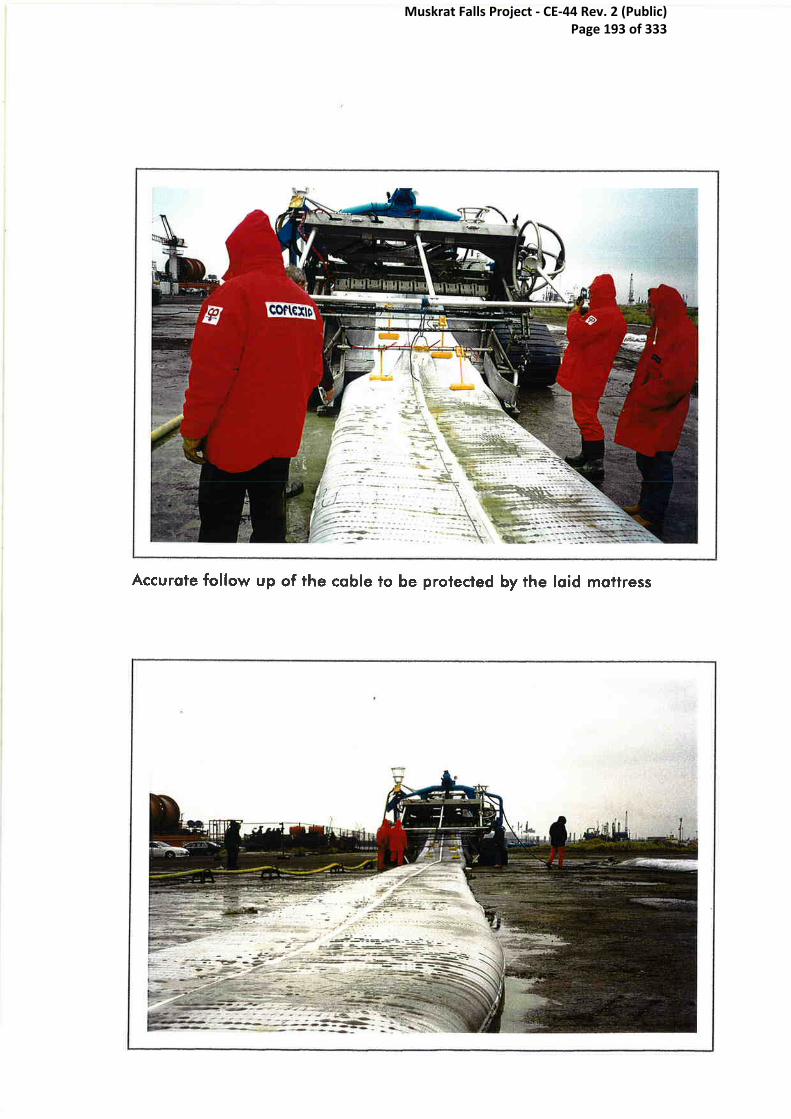
Muskrat Falls Project - CE-44 Rev. 2 (Public) Page 193 of 333

Muskrat Falls Project - CE-44 Rev. 2 (Public) Page 194 of 333

Appendix R- AHMTEC Cable Protection System
Muskrat Falls Project - CE-44 Rev. 2 (Public) Page 195 of 333
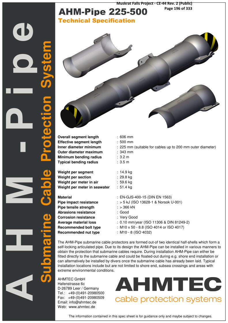
Overall segment length : 606 mm
Effective segment length : 500 mm
Inner diameter minimum : 225 mm (suitable for cables up to 200 mm outer diameter)
Outer diameter maximum : 343 mm
Minimum bending radius : 3.2 m
Typical bending radius : 3.5 m
Weight per segment : 14.9 kg
Weight per section : 29.8 kg
Weight per meter in air : 59.6 kg
Weight per meter in seawater : 51.4 kg
Material : EN-GJS-400-15 (DIN EN 1563)
Pipe impact resistance : > 5 kJ (ISO 13628-1 & Norsok U-001)
Pipe tensile strength : > 366 kN
Abrasions resistance : Good
Corrosion resistance : Very Good
Average material loss : 0.10 mm/year (ISO 11306 & DIN 81249-2)
Recommended bolt type : M10 x 50 - 8.8 (ISO 4014 or ISO 4017)
Recommended nut type : M10 - 8 (ISO 4032)
AHMTEC GmbH
Hafenstrasse 6c
D-26789 Leer / Germany
Tel.: +49-(0)491-20980500
Fax: +49-(0)491-20980509
Email: [email protected]
Web: www.ahmtec.de
The AHM-Pipe submarine cable protectors are formed out-of two identical half-shells which form a
self-locking articulated pipe. Due to its design the AHM-Pipe can be installed in various manners to
obtain the protection that submarine cables require. During installation AHM-Pipe can either be
fitted directly to the submarine cable and could be floated-out during e.g. shore end installation or
can alternatively be installed by divers once the submarine cable has already been laid. Typical
installation locations include but are not limited to shore end, subsea crossings and areas with
extreme environmental conditions.
The information contained in this spec sheet is for guidance only and maybe subject to changes.
Su
bm
ari
ne C
ab
le P
rote
cti
on
S
yste
m
AHM-Pipe 225-500Technical Specification
Muskrat Falls Project - CE-44 Rev. 2 (Public) Page 196 of 333

Appendix S- Vos Product Innovation
Muskrat Falls Project - CE-44 Rev. 2 (Public) Page 197 of 333

Pro-Pipe Cable Clamp CC- 130
Version and date 07-04-2010
Total length mmEffective length mmTotal weight (excl. bolts & nuts) kgVolume lWall thickness mmMaximum outer diameter mmMinimum inner diameter mmClamping range 96 - 110 mmSegment tensile strength kN
Submerged weight per set¹ kg
Bolt and nut size ShellsBolt and nut size Clamps
Material In accordance with EN 1563Density kg/m³Break elongation %Tensile Strength N/mm²
30020,52,81
Datasheet
Preliminary
355
17,6
8
The information contained within this product sheet is for guidance only and may be subject to change without prior notice.
130
693,7
EN-GJS-400-157200
15400
1) Based on seawater with a density of 1024 kg/m³. The density of seawater varies with temperature and salinity of the water.
M10M10
199
T +31 (0)591 315600 · F +31 (0)591 317828 · E [email protected]
www.vos-prodect.com
Pro-Pipe submarine cable & pipe protectors can be installed in various ways to obtain the protection that submarine cables and pipes require. During
installation the Pro-Pipe can be fitted directly to the cable or pipe before floating the cable in. The Pro-Pipe can also be post-lay installed by divers. As
a remedial protection the Pro-Pipe can also be installed on the beach or even offshore at locations of crossings or aggressive seabed conditions.
Please do not hesitate to ask us for detailed information
Vos Prodect Innovations B.V.
Doorndistel 1, 7891 WV Klazienaveen, The Netherlands
Muskrat Falls Project - CE-44 Rev. 2 (Public) Page 198 of 333

PRO-CPS
Pipe
Reference
Number
Minimum
Inner
Diameter
[ mm ]
Minimum
Outer
Diameter
[ mm ]
Maximum
Outer
Diameter
[ mm ]
Individual
Working
Length
[ mm ]
Total
Overall
Length
[ mm ]
Assembled
Working
Length
[ mm ]
Mass
per Segment
in Air
[ kg ]
Mass
per Meter
in Air
[ kg ]
Mass
per Meter
in Water
[ kg ]
Maximum
Bending
Angle
[ ° ]
Maximum
Bending
Radius
[ mm ]
Maximum
Cable Outer
Diameter
[ mm ]
A B C D E F G
030-250 30 44 98 250 285 1000 1,56 12,48 10,7 6 ° 2400 18
030-500 30 44 98 500 534 1000 1,93 7,72 6,6 6 ° 4800 18
040-250 40 54 106 250 287 1000 1,70 13,6 11,7 6 ° 2400 26
040-500 40 54 106 500 536 1000 2,38 9,52 8,2 6 ° 4800 26
055-250 55 71 123 250 290 1000 2,65 21,2 18,2 6 ° 2400 40
055-500 55 71 123 500 539 1000 4,00 16 13,8 6 ° 4800 40
070-250 70 86 137 250 293 1000 3,15 25,2 21,7 6 ° 2400 55070-500 70 86 137 500 542 1000 4,85 19,4 16,7 6 ° 4800 55 Pro CPS 250 series085-250 85 101 152 250 295 1000 3,65 29,2 25,1 6 ° 2400 70
085-500 85 101 152 500 545 1000 5,70 22,8 19,6 6 ° 4800 70
100-250 100 116 170 250 296 1000 4,45 35,6 30,6 6 ° 2400 85
100-500 100 116 170 500 545 1000 6,80 27,2 23,4 6 ° 4800 85
115-250 115 131 184 250 298 1000 5,50 44 37,8 6 ° 2400 100
115-500 115 131 184 500 548 1000 7,75 31 26,7 6 ° 4800 100
130-250 130 146 199 250 300 1000 5,60 44,8 38,5 6 ° 2400 110
130-500 130 146 199 500 550 1000 8,65 34,6 29,7 6 ° 4800 110
145-250 145 161 214 250 300 1000 6,40 51,2 44,0 6 ° 2400 125
145-500 145 161 214 500 550 1000 9,80 39,2 33,7 6 ° 4800 125
160-250 160 176 228 250 302 1000 7,00 56 48,1 6 ° 2400 140
160-500 160 176 228 500 553 1000 10,70 42,8 36,8 6 ° 4800 140
175-250 175 191 243 250 304 1000 7,65 61,2 52,6 6 ° 2400 155
175-500 175 191 243 500 554 1000 11,70 46,8 40,2 6 ° 4800 155
190-250 190 206 258 250 307 1000 8,50 68 58,5 6 ° 2400 170190-500 190 206 258 500 557 1000 12,90 51,6 44,4 6 ° 4800 170 Pro CPS 500 series205-250 205 221 273 250 311 1000 9,15 73,2 62,9 6 ° 2400 185
205-500 205 221 273 500 561 1000 13,90 55,6 47,8 6 ° 4800 185 All Pro-Pipe equipment has been tested and checked
220-250 220 236 288 250 313 1000 9,75 78 67,1 6 ° 2400 200 100% when delivered to our valued customers
220-500 220 236 288 500 563 1000 14,85 59,4 51,1 6 ° 4800 200
235-250 235 251 303 250 313 1000 10,80 86,4 74,3 6 ° 2400 215 Certification for the chemical or mechanical properties
235-500 235 251 303 500 563 1000 16,25 65 55,9 6 ° 4800 215 will be supplied upon request.
250-250 250 266 319 250 315 1000 11,55 92,4 79,4 6 ° 2400 230
250-500 250 266 319 500 565 1000 17,30 69,2 59,5 6 ° 4800 230 Datasheets and test reports are available upon request
Vos Prodect Innovations B.V.
Please do not hesitate to ask us for detailed information
Typical protection string for entering an I- or J-Tube6° bend restriction
Doorndistel 1, 7891 WV Klazienaveen, The Netherlands
T +31 (0)591 315600 · F +31 (0)591 317828 · E [email protected]
www.vos-prodect.com
Muskrat Falls Project - CE-44 Rev. 2 (Public) Page 199 of 333
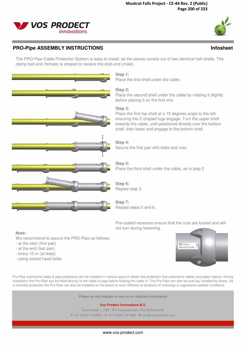
PRO-Pipe ASSEMBLY INSTRUCTIONS Infosheet
Step 7:
Repeat steps 5 and 6.
Note:
We recommend to secure the PRO-Pipe as follows:
- at the start (first pair)
- at the end (last pair)
- every 10 m (at least)
- using socket head bolts.
www.vos-prodect.com
Pro-Pipe submarine cable & pipe protectors can be installed in various ways to obtain the protection that submarine cables and pipes require. During
installation the Pro-Pipe can be fitted directly to the cable or pipe before floating the cable in. The Pro-Pipe can also be post-lay installed by divers. As
a remedial protection the Pro-Pipe can also be installed on the beach or even offshore at locations of crossings or aggressive seabed conditions.
Doorndistel 1, 7891 WV Klazienaveen, The Netherlands
T +31 (0)591 315600 · F +31 (0)591 317828 · E [email protected]
Please do not hesitate to ask us for detailed information
Vos Prodect Innovations B.V.
The PRO-Pipe Cable Protection System is easy to install, as the pieces consist out of two identical half-shells. The
clamp ball-end (female) is shaped to receive the stub-end (male).
Step 1:
Place the first shell under the cable.
Step 6:
Repeat step 3.
Step 4:
Secure the first pair with bolts and nuts.
Pre-casted recesses ensure that the nuts are locked and will
not turn during fastening.
Step 2:
Place the second shell under the cable by rotating it slightly
before placing it on the first one.
Step 3:
Place the first top shell at a 15 degress angle to the left,
ensuring the Z-shaped lugs engage. Turn the upper shell
towards the cable, until positioned directly over the bottom
shell, then lower and engage to the bottom shell.
Step 5:
Place the third shell under the cable, as in step 2
Muskrat Falls Project - CE-44 Rev. 2 (Public) Page 200 of 333

PRO-Pipe SEDIMENT FILL Infosheet
Using cast iron protectors has a lot of advantages, because:
• Heavy weight• Very High impact values• A build in Bend restrictor.• Quick assembling onto Pipe or Cable.• Assembling on board or vessel, on shore landing site or assembling by divers.• Round protectors, no obstacles to hook on or hook to (fishing nets / anchors etc).• Sediment fill
01
02
03
04
05 In certain circomstances the protector string can fully sink into the Sea / River floor, due
to weights and the shape of our Pro-Pipe protectors. Any temperature changes (high
voltage cables) will be adopted by its surrounding.
After assembling the Pro-Pipe Cable and Pipe Protectors the assembled string can be
placed into position on the Sea / River bottom. As alternative divers can place the
protection equipment at site.
The Protector String will sink onto its lowest position on the Sea / River bottom. and will
sink into the surrounding sediment (depending of Sea or River-floor conditions). Any
movements of the Protector string will be maximized by the bend restriction of the
protectors and the total weight of the protector string (incl. sediment, Cable / Pipe and
Pipe content).
Due to the enlargement of the Cable / Pipe weight, the protector string will sink into the
sediment. Because the Protector string has small openings, the sediment also will flow
inside the protectors, creating an extra protection layer around the cable or pipe, but
protected by the Pro-Pipe Protector. Due to this, the Protector string could be secured for
tidal/ wave actions.
Depending on the Sea / River floor conditions the Protector string will lower itselves into
the sediment, whereas the sediment fills up the protector string, creating an extra Cable /
Pipe Protection free of charge. As an extra feature, the sediment will creat a positive
influence for any further bending of the Protector string.
www.vos-prodect.com
Pro-Pipe submarine cable & pipe protectors can be installed in various ways to obtain the protection that submarine cables and pipes require. During
installation the Pro-Pipe can be fitted directly to the cable or pipe before floating the cable in. The Pro-Pipe can also be post-lay installed by divers. As
a remedial protection the Pro-Pipe can also be installed on the beach or even offshore at locations of crossings or aggressive seabed conditions.
Doorndistel 1, 7891 WV Klazienaveen, The Netherlands
T +31 (0)591 315600 · F +31 (0)591 317828 · E [email protected]
Please do not hesitate to ask us for detailed information
Vos Prodect Innovations B.V.
Muskrat Falls Project - CE-44 Rev. 2 (Public) Page 201 of 333
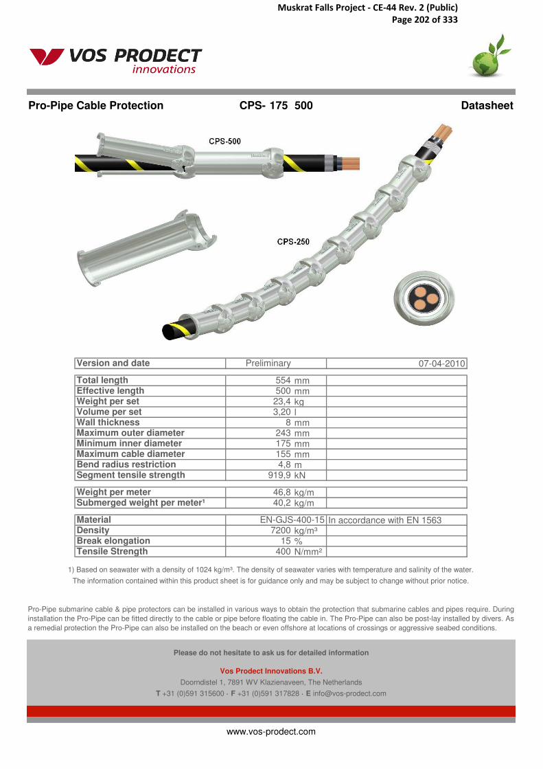
Pro-Pipe Cable Protection CPS- 175 500
Version and date 07-04-2010
Total length mmEffective length mmWeight per set kgVolume per set lWall thickness mmMaximum outer diameter mmMinimum inner diameter mmMaximum cable diameter mmBend radius restriction mSegment tensile strength kN
Weight per meter kg/mSubmerged weight per meter¹ kg/m
Material In accordance with EN 1563Density kg/m³Break elongation %Tensile Strength N/mm²
243
Datasheet
Preliminary
55450023,43,20
8
The information contained within this product sheet is for guidance only and may be subject to change without prior notice.
1751554,8
919,9
46,840,2
EN-GJS-400-157200
15400
1) Based on seawater with a density of 1024 kg/m³. The density of seawater varies with temperature and salinity of the water.
T +31 (0)591 315600 · F +31 (0)591 317828 · E [email protected]
www.vos-prodect.com
Pro-Pipe submarine cable & pipe protectors can be installed in various ways to obtain the protection that submarine cables and pipes require. During
installation the Pro-Pipe can be fitted directly to the cable or pipe before floating the cable in. The Pro-Pipe can also be post-lay installed by divers. As
a remedial protection the Pro-Pipe can also be installed on the beach or even offshore at locations of crossings or aggressive seabed conditions.
Please do not hesitate to ask us for detailed information
Vos Prodect Innovations B.V.
Doorndistel 1, 7891 WV Klazienaveen, The Netherlands
Muskrat Falls Project - CE-44 Rev. 2 (Public) Page 202 of 333

Pro-Pipe Cable Protection CPS- 175 250
Version and date 07-04-2010
Total length mmEffective length mmWeight per set kgVolume per set lWall thickness mmMaximum outer diameter mmMinimum inner diameter mmMaximum cable diameter mmBend radius restriction mSegment tensile strength kN
Weight per meter kg/mSubmerged weight per meter¹ kg/m
Material In accordance with EN 1563Density kg/m³Break elongation %Tensile Strength N/mm²
243
Datasheet
Preliminary
30425015,32,09
8
The information contained within this product sheet is for guidance only and may be subject to change without prior notice.
1751552,4
919,9
61,152,5
EN-GJS-400-157200
15400
1) Based on seawater with a density of 1024 kg/m³. The density of seawater varies with temperature and salinity of the water.
T +31 (0)591 315600 · F +31 (0)591 317828 · E [email protected]
www.vos-prodect.com
Pro-Pipe submarine cable & pipe protectors can be installed in various ways to obtain the protection that submarine cables and pipes require. During
installation the Pro-Pipe can be fitted directly to the cable or pipe before floating the cable in. The Pro-Pipe can also be post-lay installed by divers. As
a remedial protection the Pro-Pipe can also be installed on the beach or even offshore at locations of crossings or aggressive seabed conditions.
Please do not hesitate to ask us for detailed information
Vos Prodect Innovations B.V.
Doorndistel 1, 7891 WV Klazienaveen, The Netherlands
Muskrat Falls Project - CE-44 Rev. 2 (Public) Page 203 of 333

Pro-Pipe Tube Centraliser 175 xxx
Version and date 18-06-2010
Segment length (total) mm On request, depends on tube ØWeight per set kg On request, depends on tube ØVolume per set l On request, depends on tube ØMaximum outer diameter mm On request, depends on tube ØMinimum inner diameter mmMinimum inner tube diameter mm On request, depends on tube Ø
Submerged weight per set¹ kg On request, depends on tube Ø
Bolt and nut size
Material PUDensity PU kg/m³Break elongation %Tensile Strength N/mm²
-
-
--
Datasheet
Preliminary
-
TC
-
The information contained within this product sheet is for guidance only and may be subject to change without prior notice.
165
PU shore 80A125055060
1) Based on seawater with a density of 1024 kg/m³. The density of seawater varies with temperature and salinity of the water.
M10
T +31 (0)591 315600 · F +31 (0)591 317828 · E [email protected]
www.vos-prodect.com
Pro-Pipe submarine cable & pipe protectors can be installed in various ways to obtain the protection that submarine cables and pipes require. During
installation the Pro-Pipe can be fitted directly to the cable or pipe before floating the cable in. The Pro-Pipe can also be post-lay installed by divers. As
a remedial protection the Pro-Pipe can also be installed on the beach or even offshore at locations of crossings or aggressive seabed conditions.
Please do not hesitate to ask us for detailed information
Vos Prodect Innovations B.V.
Doorndistel 1, 7891 WV Klazienaveen, The Netherlands
Muskrat Falls Project - CE-44 Rev. 2 (Public) Page 204 of 333

Pro-Pipe Cable Clamp CC- 175
Version and date 07-04-2010
Total length mmEffective length mmTotal weight (excl. bolts & nuts) kgVolume lWall thickness mmMaximum outer diameter mmMinimum inner diameter mmClamping range 141 - 155 mmSegment tensile strength kN
Submerged weight per set¹ kg
Bolt and nut size ShellsBolt and nut size Clamps
Material In accordance with EN 1563Density kg/m³Break elongation %Tensile Strength N/mm²
35029,64,05
Datasheet
Preliminary
409
25,4
8
The information contained within this product sheet is for guidance only and may be subject to change without prior notice.
175
919,9
EN-GJS-400-157200
15400
1) Based on seawater with a density of 1024 kg/m³. The density of seawater varies with temperature and salinity of the water.
M10M10
243
T +31 (0)591 315600 · F +31 (0)591 317828 · E [email protected]
www.vos-prodect.com
Pro-Pipe submarine cable & pipe protectors can be installed in various ways to obtain the protection that submarine cables and pipes require. During
installation the Pro-Pipe can be fitted directly to the cable or pipe before floating the cable in. The Pro-Pipe can also be post-lay installed by divers. As
a remedial protection the Pro-Pipe can also be installed on the beach or even offshore at locations of crossings or aggressive seabed conditions.
Please do not hesitate to ask us for detailed information
Vos Prodect Innovations B.V.
Doorndistel 1, 7891 WV Klazienaveen, The Netherlands
Muskrat Falls Project - CE-44 Rev. 2 (Public) Page 205 of 333
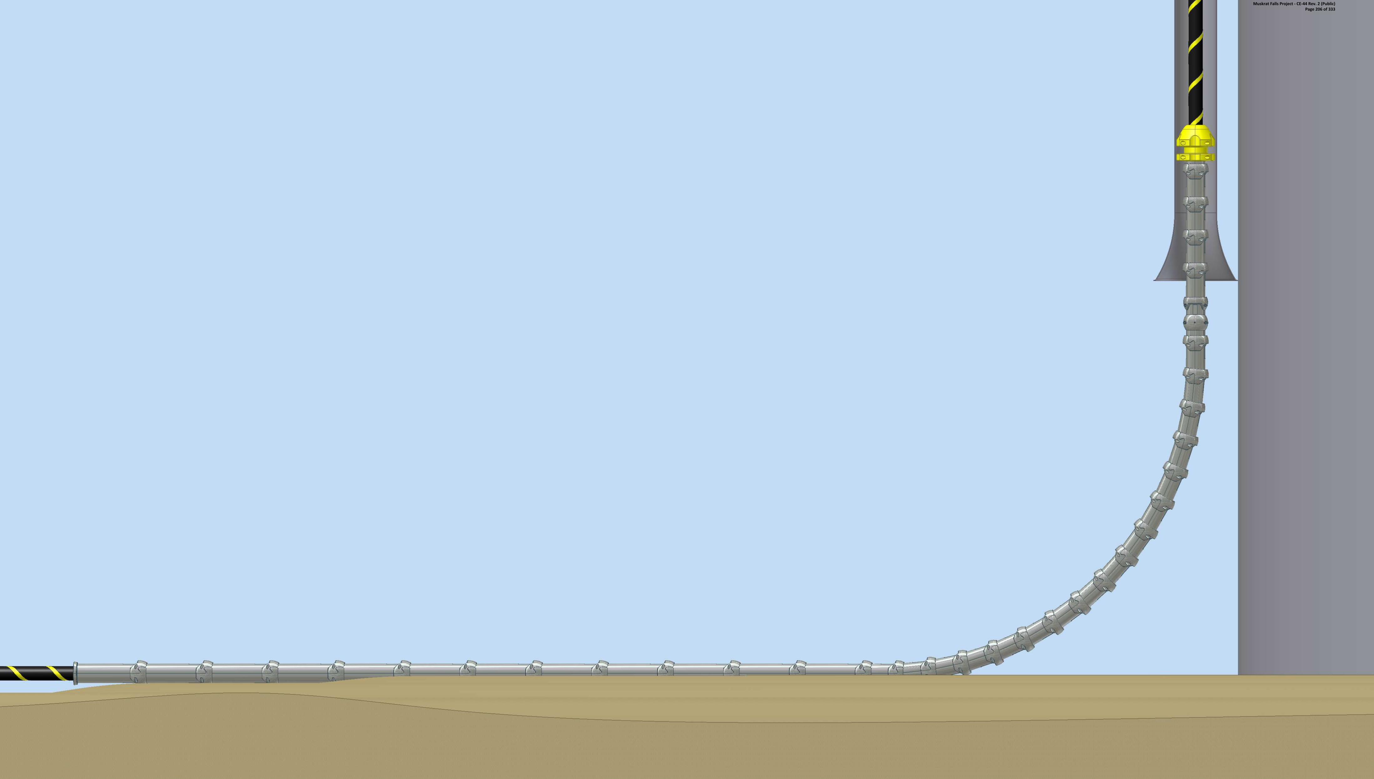
Muskrat Falls Project - CE-44 Rev. 2 (Public) Page 206 of 333

Muskrat Falls Project - CE-44 Rev. 2 (Public) Page 207 of 333

Appendix T- Serpent Cable Flotation System
Muskrat Falls Project - CE-44 Rev. 2 (Public) Page 208 of 333

Product Overview:SEASERPENT CABLE FLOTATION
SEAFLEX LTD SAMUEL WHITES COWES ISLE OF WIGHT PO31 7RA UNITED KINGDOMTelephone: +44 1983 290525 Fax: +44 1983 295853 Email: [email protected] Website: www.seaflex.co.ukThe intellectual content of this document is the copyright of Seaflex Ltd. Contents are accurate at time of going to press, but may change without notice
The form stiffness developed by the SeaSerpent decreases kinking tendenciesand eliminates sagging between floats and the requirement to keep constanttension on the cable. This characteristic, coupled with the unrivalled controlof the sinking process, allows installers much greater flexibility in procedures.It is for instance possible to park the cable on the bottom during adverse tidalperiods and re-float it when required, or tow sections of cable to installationsites several kilometres from the launch point.
The SeaSerpent eliminates losses of individual buoyancy units and saves ahuge amount of space and manpower at the launch point. With only 1.5m2 ofdeck space required for 1km of buoyancy, the SeaSerpent offers significantsavings in transport, storage and replacement costs as well as the operationaladvantages of speed and control.
Since 1996 SeaflexLimited have beencertified to ISO9002by Lloyds RegisterQuality Assurance for- ‘The manufacture,repair and hire ofheavy duty flexiblel o a d b e a r i n gstructures, primarilyair lift bags and fluidstorage tanks’.
Seaflex can manufacture SeaSerpent for individual buoyancy requirements although most cable weightsare applicable to Seaflex’s Standard Range. The table shows Standard Range SeaSerpent specifications.SeaSerpent and ancillary transport, deployment and recovery systems are available for hire or purchase.
Instead of using multiple floats to support a submarine cable during installation inshallow water, the SeaSerpent is a continuous inflatable tube attached to the cableat 1m spacing. While its support and control of the cable is excellent, perhaps itsmost advantageous characteristic is the operational flexibility it allows the installer.
Supplied in ‘lay flat’ form on a transport, deployment, recovery (TDR) drum thetube is inflated as it unwinds and is attached to the cable just before the launchpoint. This allows rapid and near continuous deployment.
When the correct length of cable is afloat and positioned accurately on its line, theair is vented from one end of the tube allowing the cable to sink progressively intothe desired position. This sinking process is under complete control and may beslowed, stopped or reversed at will.
THE CONTROLLED WAY TO INSTALL CABLES IN SHALLOW WATER
TYPEBuoyancy
(kg/m)
Lay Flat Width
(mm)
Inflated dia.
(mm)
2650/9/30 6 141 90
2650/8/25 8 160 102
2650/7/20 10 182 116
2650/6/15 13 213 136
2650/5/15 20 259 164
2650/4/12 33 320 205
2650/3/10 60 435 280
2650/2/6 130 650 420
Muskrat Falls Project - CE-44 Rev. 2 (Public) Page 209 of 333
Appendix U- Cable Laying Vessel Specifications
Muskrat Falls Project - CE-44 Rev. 2 (Public) Page 210 of 333

Owner PrysmianContractors: Pirelli/Prysmian
Length Overall 133.18 mMoulded Breadth 30.48 m
Draft at max load (operating four
thrusters)8.50 m
Moulded Depth 7.62 mLoaded Draft Summer Freeboard 5.197 mSummer Freeboard 1.79 mDeadweight Tonnage 8,840 tonsGross Tonnage 10,617 tonsNet Tonnage 3,185 tonsDeck Strength Uniform Loading 9.28 tons/m²Max speed 10 knotsBollard pull 100 tonsLight weight 8,004 tons
Diesel Engines Daihatsu 6 DV 22A V12 2,200 BHP at 1,000 RPM
GeneratorsFuji 1500 KW 600 Volt GFV 563ZB-6Z Emergency/Harbour
GeneratorEngine type Caterpillar 3508 DITA (Marine) 1500 RPMGenerator Hyundai Electrical Engineering HFC 3-454-4 500 KVA
600 Volt - 50 Hz for Propulsion440 Volt - 50 Hz for General Board Network220 Volt - 50 Hz for user supplies
Aft Two Schottel Lips Azimuth Fixed Pitch Thrusters with
Giulio Verne
The vessel is powered by five Daihatsu diesel gen sets running on gasoil
Power Supply
PROPULSION & MACHINERY
MAIN DIMENSIONS & PERFORMANCESpecifications:
Muskrat Falls Project - CE-44 Rev. 2 (Public) Page 211 of 333

Type1500/1000 ZS driven by Fuji Electric Motors 1000 RPM,
1250 kW, 600 Volt direct current.Speed control by SCR type
ForwardTwo Retractable Schottel Lips Azimuth Fixed Pitch Thrusters
with Propellers in Nozzles.
TypeS 1000 LSV driven by Fuji Electric Motors 720 RPM, 1250
kW, 600 Volt direct current Speed control by SCR type
Bulb Tunnel thrusterType Kamewa TT 1650 K/BMS-CP 710 kW, 380 V, 50 Hz.
Giulio Verne is equipped with a DP SIMRAD SDP 21
Transit Speed 9 knots in good sea and wind conditionsMaximum Speed 10 knotsConsumption in transit 15 - 20 tons/dayConsumption in DP operations 7 - 11 tons/dayConsumption in port 2 tons/day
Fresh water 650 tonsGas Oil 650 tons
Crew 18 - 40Technicians and Representatives 50 maxTotal 90
One - Radar (also A.R.P.A.) Kelvin Hughes 3 cm (Band X) Nucleus 6000 AOne - Radar Kelvin Hughes 10 cm (Band S) Nucleus 5000 TOne - Hydrographic Echo Sounder SIMRAD EA500One - Echo Sounder One - Echo Sounder JRC Type NJA 178 SOne - Echo Sounder Kelvin Hughes Type MS 50One - Doppler Log One - Doppler Log JRC type JLN 203One - GPS Satellite Navigator Furuno GPS GP 80One - GPS Satellite Navigator Furuno GPS GP 30Two - VHF Radiotelephone Sailor Type RT 144B
DYNAMIC POSITIONING SYSTEM
SPEED AND FUEL CONSUMPTION
CARGO CAPACITY AND AVAILABLE DECK AREATotal cargo capacity is approximately 8,000 tons. : The turntable has a maximum capacity of 7,000 tons of cable.On the main deck, ahead from the turntable, an area of about 500 m² is available, in which a cable
TANK CAPACITY
REFRIGERATION STORAGEFreezer Room -18°C 26 m³Vegetable Room +4°C 17 m³Dry Provision 50 m³
ACCOMMODATION
The ship is anyway certified for 96 peopleHospital with two bedsTwo Clients officesOne Officer loungeTwo Crew/General lounges
HEATING AND VENTILATIONAccommodation and laying-testing control rooms are air-conditioned
NAVIGATION EQUIPMENT
Muskrat Falls Project - CE-44 Rev. 2 (Public) Page 212 of 333
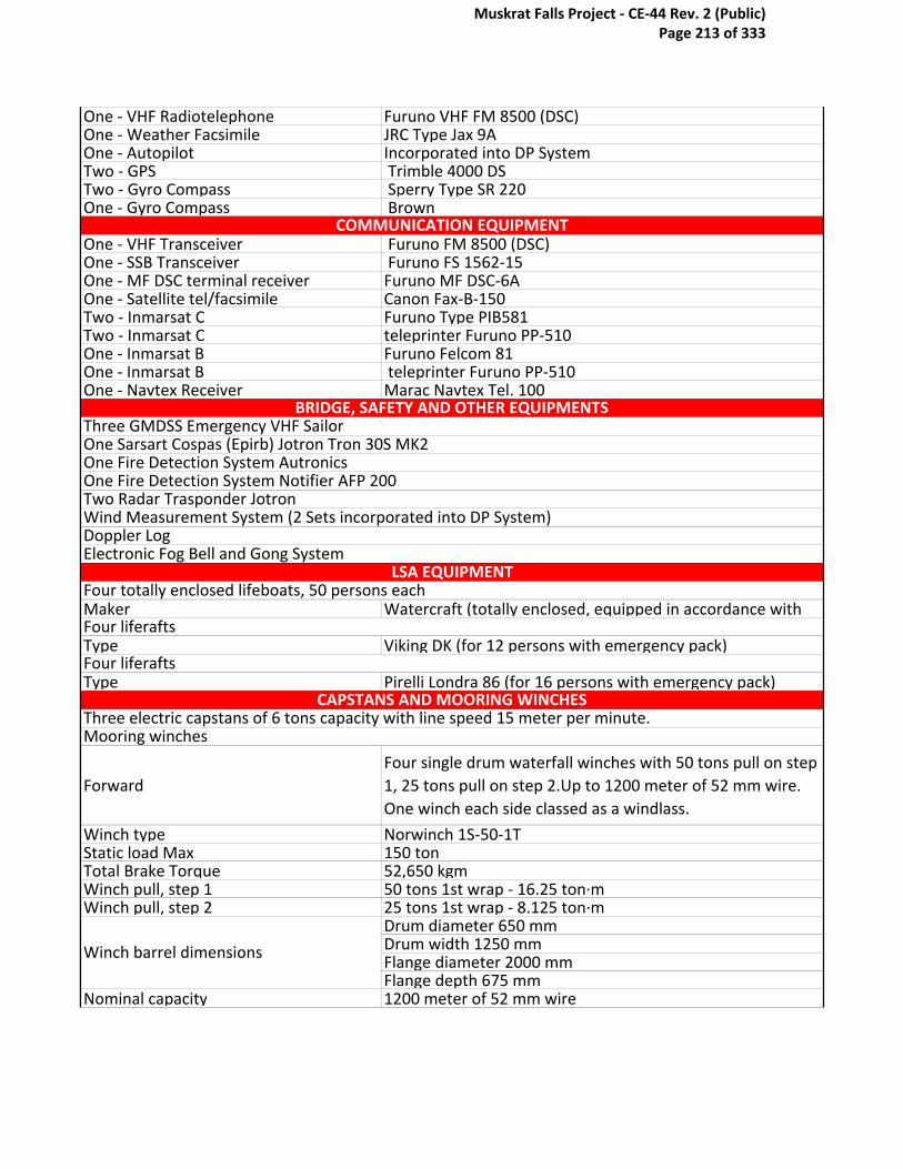
One - VHF Radiotelephone Furuno VHF FM 8500 (DSC)One - Weather Facsimile JRC Type Jax 9AOne - Autopilot Incorporated into DP SystemTwo - GPS Trimble 4000 DSTwo - Gyro Compass Sperry Type SR 220One - Gyro Compass Brown
One - VHF Transceiver Furuno FM 8500 (DSC)One - SSB Transceiver Furuno FS 1562-15One - MF DSC terminal receiver Furuno MF DSC-6AOne - Satellite tel/facsimile Canon Fax-B-150Two - Inmarsat C Furuno Type PIB581Two - Inmarsat C teleprinter Furuno PP-510One - Inmarsat B Furuno Felcom 81One - Inmarsat B teleprinter Furuno PP-510One - Navtex Receiver Marac Navtex Tel. 100
Maker Watercraft (totally enclosed, equipped in accordance with
Type Viking DK (for 12 persons with emergency pack)
Type Pirelli Londra 86 (for 16 persons with emergency pack)
Forward
Four single drum waterfall winches with 50 tons pull on step
1, 25 tons pull on step 2.Up to 1200 meter of 52 mm wire.
One winch each side classed as a windlass.
Winch type Norwinch 1S-50-1TStatic load Max 150 tonTotal Brake Torque 52,650 kgmWinch pull, step 1 50 tons 1st wrap - 16.25 ton·mWinch pull, step 2 25 tons 1st wrap - 8.125 ton·m
Drum diameter 650 mm Drum width 1250 mmFlange diameter 2000 mmFlange depth 675 mm
Nominal capacity 1200 meter of 52 mm wire
COMMUNICATION EQUIPMENT
BRIDGE, SAFETY AND OTHER EQUIPMENTSThree GMDSS Emergency VHF SailorOne Sarsart Cospas (Epirb) Jotron Tron 30S MK2One Fire Detection System AutronicsOne Fire Detection System Notifier AFP 200Two Radar Trasponder JotronWind Measurement System (2 Sets incorporated into DP System)Doppler LogElectronic Fog Bell and Gong System
LSA EQUIPMENTFour totally enclosed lifeboats, 50 persons each
Four liferafts
Four liferafts
CAPSTANS AND MOORING WINCHESThree electric capstans of 6 tons capacity with line speed 15 meter per minute.Mooring winches
Winch barrel dimensions
Muskrat Falls Project - CE-44 Rev. 2 (Public) Page 213 of 333

Aft
Two double drum waterfall winches with 80 tons pull using
both motors onto one drum, 40 tons pull using one motor
on each drum. 1200 meter of 52 mm wire.
Winch type Norwinch 2S-80-2TStatic load maximum 150 ton - 1st wrapWinch pull (2 into 1 80 ton 1st wrap- 28.4 ton·mWinch pull (1 into 1 40 ton 1st wrap - 14.2 ton·m
Drum diameter 710 mmDrum width 1500 mmFlange diameter 1850 mmFlange depth 570 mm
Nominal capacity 1200 meter of 52 mm wire
Hook capacity 25 tons at 22 metres; revolving capacity on
One Electric 2 tons Store Davit next to accommodation
starboard side
One Sormec crane 13 tons at 6 m
Fitted with motorised wheels3 m bending radius
DOHB machine Caterpillar typeMaximum pulling tension 5 tons at 2 knots in laying mode6 m diameterLaying performance:50 tons at 2 knots20 tons at 5 knots Recovering performance:50 tons at 0.5 knots20 tons at 1 knotCaterpillar typeMaximum pulling tension 2 tons (seaward)6 m diameterFitted with dynamometer for max 50 tons
Fitted with motorised wheels3 m bending radius
Linear machine Maximum pulling tension 10 tons in laying/recovering6 m diameterFitted with dynamometer for max 20 tons
Winch Barrel dimensions
CRANAGE
Four Asea cranes
Eight Flipper Delta Anchors of 7 tons eachANCHORS
CABLE LAYING EQUIPMENTSTARBOARD LAYING LINE
Pick-up arm
Capstan
Carousel outer diameter 25 mCarousel inner diameter 6 m
Auxiliary machine
Stern sheave
PORTSIDE LAYING LINE
Pick-up arm
The maximum diameter is 19 m; the maximum capacity is approx. 2500 tons of cable
Carousel height 4 m (extendible to 4.5 m)Maximum linear speed at inner diameter: 2 knots
FIXED CABLE STORAGE AREAAhead from the turntable an area is available where a fixed platform for coilable cables can be
Stern sheave
7000 TONS TURNTABLE
Muskrat Falls Project - CE-44 Rev. 2 (Public) Page 214 of 333
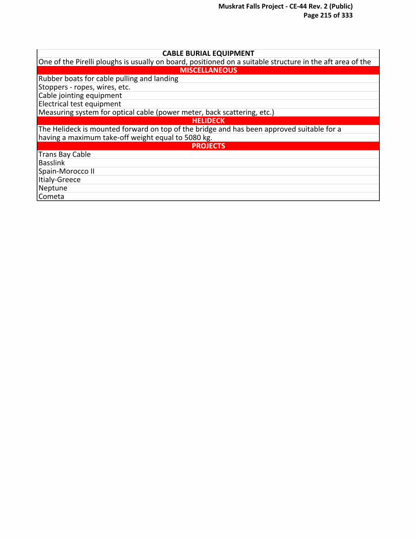
PROJECTS
CometaNeptuneItialy-Greece Spain-Morocco II BasslinkTrans Bay Cable
The Helideck is mounted forward on top of the bridge and has been approved suitable for a having a maximum take-off weight equal to 5080 kg.
Rubber boats for cable pulling and landingStoppers - ropes, wires, etc.Cable jointing equipmentElectrical test equipment
HELIDECK
One of the Pirelli ploughs is usually on board, positioned on a suitable structure in the aft area of the CABLE BURIAL EQUIPMENT
MISCELLANEOUS
Measuring system for optical cable (power meter, back scattering, etc.)
Muskrat Falls Project - CE-44 Rev. 2 (Public) Page 215 of 333

Muskrat Falls Project - CE-44 Rev. 2 (Public) Page 216 of 333
Owner NexansContractors: Nexans
Length oa including laying wheels 106.00 mBreadth moulded 32.15 mDepth moulded 8.00 mDraft an max deadweight with bow 8.13mDeadweight 7886 tBallast capacity 4400 tVessel speed 10 ktsClassification DNV 1A1 Cable Laying Vessel E0 DYNPOS-AUTR
Power generation 4 x 500 kVA1 X 600 kVA
Stern thrusters 2 x 1943 kW (2640 HP) azimuth units1 X 1000 kW (1360 HP) azimuth unit
Bow thrusters 1 x 1820 kW (2475 HP) retractable azimuth unit1 x 957 kW (1300 HP) tunnel unit
NMD/IMO class 2ERN 99.99.99Type Simrad ADP-503Reference systems 2 x DGPS
1 x tracking USSBL transducer1 x Artemis mk III1 x Fanbeam (Optional)
Main turntable Outer diameter : 29 mInner diameter : 12 mLoad capacity : 6600 t
Deck area Approx. 650 m^2
C/S Bourbon Skagerrak
Specifications:
PROPULSION & MACHINERY
MAIN DIMENSIONS & PERFORMANCE
DYNAMIC POSITIONING SYSTEM
CARGO CAPACITY AND AVAILABLE DECK AREA
Muskrat Falls Project - CE-44 Rev. 2 (Public) Page 217 of 333
Deck capacity 10 t/m^2
Single cabins 49Hospital (Single) 1
A & R winches 2 x 30 t SWL linear winchesStern cherry pickers 2 x hydlaulic manriding cherryCable capstan system Cable capstan with linear engine.Total pull/breaking capacity : 50 tMaximum laying speed : 50 m/min
A-Frame 40 t SWLMain crane forward 20 t SWLAft deck crane 3 x 5 t SWL
Laying wheels 1 x 10 m diameter stern wheel1 x 5 m diameter stern wheel
Cable guiding Complete guiding of cablefrom turntable to laying wheel.Guiding minimum radius : 5 m.
Laying instrumentation Computer based laying controlsystem with thefollowing input sensors:2 x lay speed/length sensors1 x lay wheel load sensor1 x cable top angle sensor1 x high accuracy echo sounderPlus depth and position of ROVduring touch down monitoring.
ROV ARGUS Mariner XLTrenching (Option) The vessel can carry Capjet 1 MV trenching
units for burial operations
Splice areaA 3 x 15 meter, enclosed area is purpose designed for
performance of High Voltage cable repair.
Cable splice eq.All required equipment for splicing can be accommodated
with ready connections to ship utilities
Cable handling eq.Main equipment for cable handling during a repair is
permanently stored onboard
Other
The vessel can be fitted with further equipment from our
cable handling tool pool. Thus the vessel can perform :
*Cable repair including subsea cutting and retrieval of
damage sections. *Simultaneous laying of two cables with
controlled separation. *Piggyback laying
Availability: Booked couple year waiting list (3 years Approx)Availability:
MISCELLANEOUSCable repair equipment
ROV
ACCOMMODATION
CAPSTANS AND MOORING WINCHES
CRANAGE
CABLE LAYING EQUIPMENT
Muskrat Falls Project - CE-44 Rev. 2 (Public) Page 218 of 333

Skagerrak 1&2
Skagerrak3Cook StraightFennoSkan2FennoSkan
BP ValhallSAPEINorNedMoyle
French Island (La Reunion in the Indian Ocean) (XLPE)Lincs (windfarm) (XLPE)London Array (windfarm) (XLPE)COMETA
Hainan Island -Chinese Mainland (Oil Filled)Spanish Mainland - Balearic Island (Cometa Cable)Islands in Krabi (Southern Thialand) (XLPE)Sheringham Shoal (windfarm)(XLPE)
Long Island Replacement (XLPE)Abu Dhabi-Delma IslandHorns Rev 2 (AC XLPE)Wolfe Island(XLPE)
PROJECTS
Muskrat Falls Project - CE-44 Rev. 2 (Public) Page 219 of 333

Owner Nico Middle EastContractors: Oceanteam
Type: DP II Cable andYear Built / Builder: 1999, De Hoop B.V., Lobith,Port/No of Registry KingstownCall Sign : J8B2641Class: DNV+1A1 Cable lay vessel DYNPOS AUTRLength Overall 86.00 mBreadth Moulded 24.00 mDepth Moulded 5.50 mDraft Loaded 4.50 mFreeboard 1.013 mDeadweight 5320 tonnes
4073 tonnesNRT 1221 tonnes
4 x CAT. 3512 DITA 1445 kWeach at 1800 rpm
Main Propulsion 2 x electric driven Azimuth thrustersmake Schottel type SRP 1212 FP withfixed pitched propellers, 1200KW each1 x 1200 kW retractable Azimuth1 x 1100 kW Tunnel Thruster4 x Leroy Somer, LSA 51L960 Hz, 480 V, 1800 kVA each
Emergency Generator 1 x 219 kVA 175 kW – 238 HPSewage Treatment Plant Aquamar Bio-Unit Mod. MSP IIIOily Water Seperator DVZ – VL
Alstom Cegelec
Team Oman
Specifications:MAIN DIMENSIONS & PERFORMANCE
Auxiliary / Generators
Registered Tonnage
DYNAMIC POSITIONING SYSTEM
DP System
PROPULSION & MACHINERY
Main Engines
Stern Thrusters
Bow Thrusters
Muskrat Falls Project - CE-44 Rev. 2 (Public) Page 220 of 333

DPS 902 DuplexCegelec 900 seriesforward & aft control
Max Speed Approx. 10 knotsEconomical Speed Approx 8 knotsFuel Consumption Appox. 10 ton/day
Inside diameter 8 mOutside diameter 24 mHeight 4 mSurface ring 379 mCVolume of ring 1515 mDTurn table Speed 2 rpm max
Outer Diameter 15mInner Diameter 4 mDeck Cargo Capacity 5000 tonnesClear Deck Area 61 x 24 m. 1464 mC
Fuel Oil 545 mDFresh Water 2900 mD
Refrigerator / Freezer 2 x 28 mD each
Crew + Catering Abt. 18 + 5Passengers Abt. 33
Magnetic Compass 1 x DatemaGyro Compass Sperry SR 180 MK 1Gyro Repeaters 2 x C PlathAuto Pilot 2 x Alstom
1 x Furuno FAR 28151 x FR-2135 Sand FMD-8010Furuno FE 606Navisound – 210
Depth Indicator Furuno ED 222Navtex Receiver 1 x Furuno NX 5000
1 x Leica K 10 DGPS1 x Garmin GPS-128
Doppler Speed Lod Furuno DS 70
GMDSS Station 1 x Furuno Area 3 SSB 1 x FurunoVHF (4) FurunoSatellite Phone / Fax NeraInmarsat Satcom B, C
1 x McMurdo E3Pains Wessex
SART 2 x JXJ Tron Sart
STATIC COIL (Optional)
TURN TABLE / 4800 TonnesCARGO CAPACITY AND AVAILABLE DECK AREA
DP System
SPEED AND FUEL CONSUMPTION
COMMUNICATION EQUIPMENT
EPIRB
NAVIGATION EQUIPMENT
Radars (ARPA)
Echo Sounder
GPS
TANK CAPACITY
REFRIGERATION STORAGE
ACCOMMODATION
Joystick
Muskrat Falls Project - CE-44 Rev. 2 (Public) Page 221 of 333
20 x COc, 12 x Foam,10 D/P
Emergency Fire / Pump 1 x 50 mD/hrFlooding System inGenerator Room
Life rafts 8 x 15 personsRescue / Workboat 6 persons
4 x electric selftensioning winches2 x 60 tonnes& 2 x 48 tonnes2 x 3.5 tonnes& 2 x 2.5 tonnes2 x 10 tonneselectric driven
Bollard Pull 40 M tonnes
15 tonnes26.5 m reach
A- Frame 24 tonnes SWLSupply Crane 4 tonnes
4 Point Mooring system
Anchors
Capstans
CRANAGE
Deck Crane
LSA EQUIPMENT
BRIDGE, SAFETY AND OTHER EQUIPMENTS
Fire Extinguisher
Fixed CO2
CAPSTANS AND MOORING WINCHES
Muskrat Falls Project - CE-44 Rev. 2 (Public) Page 222 of 333

Owner Global MarineContractors: Global Marine
Type of Ship Cable ShipBuilders Kvaerner Masa Shipyard,Turku,Finland 1995IMO Number 9101132ABS I.D. 95146744Call Sign MVEP4Port of Registry LondonLength Overall 145.50 metresLength Between Perpendiculars 124.12 metresBreadth Moulded 24.00 metresDepth Moulded (to Deck 3) 13.5m metresDesigned Draft 8.30 metresDeadweight 10557 tonnesSummer Draft 8.517 metresGross Registered Tonnage 14277 tonnesNet Registered Tonnage 4283 tonnesSuez Tonnage 15619.1 tonnesPanama Tonnage 11977 tonnesClassifications Cable Layer. A1, AMS, ACCU, DPS-2
Main Engines 3 xWARTSILA 9R32E @ 3645kW
-1 x Bow Thrust - White Gill GEC Elliot 70T3S - 24t -1 x Bow
Thrust - Tunnel - KAMEWA - 16t, provides excellent
manoeuvring capabilities
- 2 x Stern tunnel - KAMEWA - 12t eachAuxiliary Services None
Cable Innovator
MAIN DIMENSIONS & PERFORMANCE
PROPULSION & MACHINERY
Specifications:
Auxiliary Engines 2 xWARTSILA 6R22/2E @ 975 kW
Thrusters
Muskrat Falls Project - CE-44 Rev. 2 (Public) Page 223 of 333

Switch boards 3.3 kV Main Switchboard, 440v / 60 Hz distributionEmergency generator 1 x CUMMINS 350kW
Dynamic positioning system Converteam DPS A-Series - Version 4 (Duplex)
Fuel Consumption in Port 4t/dayFuel Consumption Cable Laying 10-18t/dayFuel Consumption Economic 16t/dayFuel Consumption Transit 12 knots @17-27t/day dependent upon load/weatherFuel Consumption Max Speed 35t/dayMaximum Bunker Capacity 1662 tonnes
EnduranceNormal 42 days at sea and with logistical can be extended
to approx. 60 days
Economic Speed: 10 KnotsService Speed: 12 KnotsMax Speed: 16.9 Knots
Main cable tanks 3Internal Diameter 16.7mCone Outter Diameter 3.5-3.1 (Tapered)Tank Height 9.4mCone height 7.2mMaximum load per tank 2333 tonnes NominalTank Top Loading 14 tonnes/square meterVolume Of Cable Tankes 1808 m^3Spare Cable Tanks 1Internal Diameter 8.8mCone Outter Diameter 2mTank Height 9.2mMax Load per Tank 500 tonnesVolume Of Spare Tank 323 m^3
Fresh Water Capacity 1322.8 tonnesFresh Water Usage 16-20 tonnes/day
Fresh Water Generation2 x ALPHA LAVAL JWP-26-C80 20 tonnes/ day dependent
upon engine load condition.
Total Berths 80Officer Cabins 42Crew Cabins 36Representative Suites 2Hospital 2 beds
Radars 9800 ARPA and SAM Electronics NG30281 x Trimble + Probeacon DGPS2 x JAVAD + Varipos DGPS1 x Fugro 90938 + Redbox Starfix DGPS
Infrared-laser 1 x Cyscan2 x Sperry Mk371 x SG Brown TSS Meridian Standard
Speed:
ACCOMMODATION
NAVIGATION & COMUNICATION EQUIPMENT
Gyro Compasses
SPEED AND FUEL CONSUMPTION
CARGO CAPACITY AND AVAILABLE DECK AREA
DYNAMIC POSITIONING SYSTEM
GPS
TANK CAPACITY
Muskrat Falls Project - CE-44 Rev. 2 (Public) Page 224 of 333

Magnetic Compasses JC Krohn MOD390Control Unit Auto pilot Trackpilot Atlas 1100Rudder angle indicator YesNavtex JRC NCR 300A
2 x Simrad EA 500 (Deep water), 1 x Simrad EN 200(Shallow water)- Joystick Manual/Auto Heading- Duplex DP- Auto Track- Min Power- ROV Follow- Plough/Trencher High Tension Slow DownMixed Manual / Auto mode Auto Heading / PositioningThruster Allocation / ControlPower Load monitoring Blackout PreventionTrainer / Simulator ModeAlarm SystemAuto Track (high speed) / Auto Track (low speed)Follow Target mode / ROV followCable Laying / Trenching
Fire Alarm ConsiliumGMDSS JRC
1 x SAT B - NERA1 x SAT C - SAILOR DT 4646E1 x SAT C - JRC NDZ-127CMF/HF - SAILOR HC4500BVHF - JRC JHS-31JUE - 45A JRC1 x SEA-TEL KU BAND VSAT35 tonne SWL (Sea State 5)Plough tow winch SWL 100T1 x Forward (Hydralift) 2.0T @ 10.0m1 x Forward (Hydralift) 5.0T @ 10.0m2 x Aft (Manufacturer Hydra lift)10T @ 8.0m, 2T @ 18.5mTugger Winches 4 x 2T SWL
LCE 21 wheel pair Linear Cable Engine (Dowty)Cable Drum Electrically driven cable drum with fixed angled pay out Diameter 4mPull Load 40 tonnes/ knotBrake Load 40 tonnes
6.6 knots max
- 4 wheel pair Hydraulic Drive DO/HB unit, with a hydraulic
cable diverter.
- 1 x 2 wheel pair Dowty Hydraulic - Drive Cable Transporter
Sat-Com
Echo Sounder
Drum Speed
CABLE LAYING EQUIPMENT
Modes of Operation
Stand by mode
A Frame
Cranes
Muskrat Falls Project - CE-44 Rev. 2 (Public) Page 225 of 333

- 1 x 2 wheel pair Dowty Electric - Drive Cable Transporter
- 2 x 1 wheel pair Dowty Hydraulic Drive Cable Transporter
(In line)
Repeater Stowage3 temperature controlled repeater stacks situated adjacent
to each main cable tank. Total repeater capacity of 135.
ROV• A 2000m depth rated work class ROV side launched• An optional observation class ROV is provided from a deck mounted A-Frame
Muskrat Falls Project - CE-44 Rev. 2 (Public) Page 226 of 333
Owner N/AContractors: Statnett
Builders: Van de Geiessen-de Noordm, NetherlandsIMO Number: 8918629ABS I.D: 91143143Call Sign: MNNU8Port of Registry: Southampton (British)Length Overall: 130.70 metres (inc. gantry)Length Between Perpendiculars: 116.68 metresBreadth Moulded: 21.00 metresDepth Moulded (to Deck 4): 13.00 metresDesigned Draft: 7.014 metresDeadweight: 7417 tonnesSummer Draft: 2.508 metresGross Registered Tonnage: 11242 tonnesNet Registered Tonnage: 3372 tonnesSuez Tonnage: 12121.25 tonnesPanama Tonnage: 12034.94 tonnesClassifications: ABS Ice Class 1C 14445 kw,AMS, ACCU, DPS2
Propulsion and Electric Power
Generation6.6 KV Generating Sets
2 x Stork Wartsila SW280 12 Cylinder 3.1 MWE at 750 RPM
each
2 x Brush Alternators 3.8 MVA @ 6.6 KV each1 x Stork Wartsila SW280 16 Cylinder 4.2 MWE at 750 RPM
each1 x Brush Alternator 5.1 MVA @ 6.6 KV
PROPULSION & MACHINERY
CS Sovereign
Specifications:
For Propulsion & services comprising:
MAIN DIMENSIONS & PERFORMANCE
Muskrat Falls Project - CE-44 Rev. 2 (Public) Page 227 of 333

Auxilliary GeneratorFor Harbour use only: 1 x Stork Wartsila FHD 240 G 6 Cyl
0.75MW at 750RPM
2 x Ulstien Type 375 TV-C, variable pitch, (Motor output
each 1.0 MW) Max Lateral Bow
Thrust 2 x 14 tonnes
Azimuth Stern Thrusters: 2 x Lipps Type S2514 LSCP 360° azimuth thrusters each with
a nozzle
Fuel Consumptions:95% max capacity, 1108 Tonnes Marine Gas Oil (Max Lift,
No reserve allowed)
Economic Speed: [email protected] tonnes/dayMax Speed: 12.5@28 tonnes/dayEndurance: 30 days at 12 knots
Main Cable Tanks 2Internal Diameter: 17.00mCone Outer Diameter: 3.00mTank Height: 8.00mCone Height: 6.5mMaximum Load per Tank: Equating to 2668 tonnes eachTank Top Loading: 15 tonnes/sq mVolume of Cable Tanks: 1327 cubic metresMain Wing Tanks: 2Internal Diameter: 6.60mCone Outer Diameter: 2.45mTank Height: 8.00mCone Height: 6.60mMaximum Load per Tank: 2668 tonsTank Top Loading: 15 tonnes/ sq mVolume of Wing Tanks: 199 cubic metres
Fresh Water Capacity: 720 tonnesFresh Water Usage: Approx. 15 tonnes/ day
Total Berths: 76Officer Cabins: 13Crew Cabins: 23 x Single, 19 x DoubleRepresentative Suites: 2Hospital: 2 Berth Hospital (Deck 5)
Radars: 2 x Kelvin Hughes Nucleus 6000A ‘X’&‘S’ Band
Interchangable
2 x Leica Mk412 DGPS1 x Racal Skyfix Decoder 909382 x JAVAD dual GPS GLONASS DGPS Rxs
Gyro Compasses: 2 x Sperry SR-2201 x Sperry Navigat X Mk2
ACCOMMODATION
NAVIGATION & COMUNICATION EQUIPMENT
Bow Thrusters
SPEED AND FUEL CONSUMPTION
Navigation Receivers:
CARGO CAPACITY AND AVAILABLE DECK AREA
TANK CAPACITY
Muskrat Falls Project - CE-44 Rev. 2 (Public) Page 228 of 333

Echo Sounder: 1 x Marconi International Marine Seachart 3 (0 - 1200
Metres)
1 x Honeywell Elac LAZ 4400 (0-15000 metres) with wide
beam transducer
DP Vertical Reference Units: 2 x unitsDP Acoustic Reference System: 1 x Sonardyne System
DP Taut Wire Reference System: 2 x CEGELEC units - max operating depth approx. 300metres
DP Artemis Reference System:
1 x Artemis Mk 4 - ships station only. Cyscan Reference
System: 1 x Cyscan short range ref system (hired in)
(mobilised as required)
NavTex: 1 x ICS Nav 5 NAVTEXSatcom: 1 x SAT C
2 x SATCOM B1 x SEA-TEL KU BAND VSAT
Fitted with ‘Navigator’ survey spread for instant & accurate
position referencing and post processing capability to meet
all clients needs.
A Frame: 35 tonnes
ROV Crane SWL: 1 x Fassi Retractable Crane. 1.0 tonnes @ 10.10m, 5.57
tonnes @ 2.54m
Forward Cranes: 1 x 5 tonne @ 20m, 2 x Gantry Hoists (5 Tons Each)Aft Cranes: 2 x 2 tonne @ 6m
Forward Machinery: 2 x Hydraulic Powered Drums & 4 Wheel Pair Haul-off gear.
Drum Diameter: 3.50mDrum Speed: 12.6km/hr @ 25kNPull Load: 400kN @ 2.5km/hr
Haul-off Gear: 4 Pair Opposed Wheel unit. Variable tension 0 to 4 tonnes
Cable Transporters:1 x Hyrdaulic Powered 2 Wheel Pairs - 2 tonne pull, 1 x
Hydraulic Powered single Pair
Aft Machinery: 1 Hydraulic Powered Drum & 6 Wheel Pair Haul-off gear.Drum Diameter: 4.00mDrum Speed: 14.4km/hr @ 20kNPull Load: 200kN @5.4km/hr
Haul-off Gear: Electrically Powered 6 Pair Vertical Wheel unit. Variable
Tension 0 to 4 tonnes.
Auxilliary Haul-off gear: Dowty 2 Pair Vertical, Hydraulic Powered machine 1.5 tonne
pull.
CRANAGE
CABLE LAYING EQUIPMENT
Muskrat Falls Project - CE-44 Rev. 2 (Public) Page 229 of 333

ROV: PowerfulTrenching/World class Atlas 1
Repeater Stowage 90 with Portable Stacking
MISCELLANEOUSCertification of Financial repsonsibility - Water Pollution
ROV
Muskrat Falls Project - CE-44 Rev. 2 (Public) Page 230 of 333

Owner Oceanteam/McdermottContractors: Oceanteam/ABB
Vessel 102Cable & Umbilical lay vesselConstruction Support Vessel
Delivery On ScheduleYear Built 2009Length OA 137mLength BP 120.4mBeam 27 mDraft Max 6.85mDepth Main Deck 9.7mSpeed fully loaded 15 knotsDeadweight 10000 tons
Propulsion:
2 x 3500 kW c.p.p. Azipull aft
1 x 1500 kW Retracktable Azimuth c.p.p. forw
1 x 1500 kW SS Tunnel Thr. c.p. forw.
1 x 1500 kW SS Tunnel Thr c.p.p. forw.
Mark Kongsberg Maratime K-Pos 21Class DnV Dynpos-AUTR complies NMD class 2
Product capacity 7000mtonsDeck space 2400m^2Deck Strength 10 tonnes/m^2Deck Hatches two 4x3m, one with coaming
Accommodation 199 people
PROPULSION & MACHINERY
CARGO CAPACITY AND AVAILABLE DECK AREA
ACCOMMODATION
North Ocean 102
Type
MAIN DIMENSIONS & PERFORMANCESpecifications:
DYNAMIC POSITIONING SYSTEM
Muskrat Falls Project - CE-44 Rev. 2 (Public) Page 231 of 333

Deck Winch 140 tonnes SWL, wier rope
Knuckle Jib Crane Aftships, PS100 tonnes AHC @ 6m25 tonnes @ 32m
Auxiliary 10 tonnes @ 34m Provision Crane S.W.L. 2 tonnes @12m
Helideck D-Value 20.88m
Moon pool 7.2 / 7.2 m
Product collection
Rapid product loading, state of the system
Large product carrying capacity (5000t/7000t)
High transit speed fully loaded, 15 knots
DP2, weather operability sea state
Stabalizing Equipment Two passive roll reduction tanks one ant heating systemsPROJECTS
CICSA (Oil and Gas)BritnedProject STATOILHydro GJØA
CAPSTANS AND MOORING WINCHES
MISCELLANEOUS
HELIDECK
CRANAGE
Main Crane
Muskrat Falls Project - CE-44 Rev. 2 (Public) Page 232 of 333
Owner vsmcContractors: Global Marine
Type of vessel DP2 special service workboat
ClassBureau Veritas +Hull +Mach +AUT UMS +Dynapos AM/AT R
Special Service Workboat - Unrestricted Navigation
Trading area Unrestricted navigationFlag The NetherlandsLength over all 90,0 mMoulded depth 6,5 mMoulded Width 28,0 mMaximum draught 4,70 m (7,00 m bow thrusters down)Minimum draught approx. 1,90 m (4,20 m bow thrusters down)Gross Tonnage 5.551 GTDeadweight 6.901 ton
Main engines 2x Caterpillar 3512HDStern thrusters 2x HRP 6111 azimuting thrusters 1140 kW
Bow thrusters2x Caterpillar 3512B 2x HRP 6111 retractable azimuting
thrusters 1118 kW
1x Electric driven tunnel thruster 650 kWAuxiliary / Generators 3x 850 kW Parallel running/PM SystemEmergency/Harbour generator 1x 200 kW
Regulatory approved BV Class AM/AT R
Speed (maximum with minimum draft) Approx. 10 knotsFuel oil capacity Up to 1.400 m3Fuel consumption Subject to kind of work
CARGO CAPACITY AND AVAILABLE DECK AREA
PROPULSION & MACHINERY
DYNAMIC POSITIONING SYSTEM
Stemat Spirit
Specifications:MAIN DIMENSIONS & PERFORMANCE
SPEED AND FUEL CONSUMPTION
Muskrat Falls Project - CE-44 Rev. 2 (Public) Page 233 of 333

Open deck space 1.500 m2Deck strength 15 ton / m2
Fresh water maker plant 2x 12 m3/hrFresh water tank capacity Approx. 300 m3Ballast system tank capacity Approx. 2.000 m3Ballast pumps 2x 400 m3/hr
Single / Double cabins 28-AprHospital (single) 1Total number of beds / POB 60Air-conditioning / electric heatingClient office 2Conference room 1Deck store 2
Magnetic Compass Cassens & Path Reflecta 1Satellite communications Seatel VSAT 4006DGPS navigator 2x Furuno GP-150DNavigation echosounder 2x Furuno FE-700Marine radar 1x Furuno FAR-2117/1xFuruno FAR-2137SSpeedlog Furuno DS-80
Gyro compass1x Anschutz Standard 22 G/GM + 2x Anschutz Standard 22
CompactAIS system Furuno FA-150VHF radiotelephone Transceiver 3x Furuno FM-8800SMF/HF radiotelephone Transceiver Furuno FS-1570Inmarsat C terminal 1x Furuno Felcom 15 + 1x Furuno Felcom 15SSASInmarsat F terminal 1x Thrane-Thrane F33Navtex receiver Furuno NX-700Windsensor 2x Observator OMC-160
Position Reference SystemsGlonass Javad LGG100 Fanbeam MDL Fanbeam 4.2 GPS
Trimble DSM-232
Vessel Control System L-3 NMS6000, comprising:
Class 2 Dynamic Positioning System, Thruster Control
System, Environmental and Position Reference Sensors
GMDSS portable VHF transceivers 3x Jotron TR-20Epirb Jotron Tron-40SRadar transponder 2x Jotron Tron SartGSM telephone Sagem RT-3000Satellite TV system Seatel 5004Voyage Data Recorder (VDR) Danelec DM-500Chart software Transas Navigator Pro
MOB / Lifeboat 1Lifeboat 1
6 Point Mooring System 6x 60 ton pull/100 ton hold full C.T.
TANK CAPACITY
ACCOMMODATION
NAVIGATION & COMUNICATION EQUIPMENT
LSA EQUIPMENT
CAPSTANS AND MOORING WINCHESThe vessel comply with Solas, IMO and Marpol requirements
Muskrat Falls Project - CE-44 Rev. 2 (Public) Page 234 of 333

Hydraulic deck crane 18 ton at 14 m (hook) / 15 ton at 16 m single line (winch)
Anchor wires 6x 1.000 m / 48 mmAnchors 6x SSHP anchor 7 tonnes
Incinerator 25 kg/hr
CRANAGE
ANCHORS
Sewage treatment plant
PROJECTS
Walney 1Offshore Wind Farm
MISCELLANEOUS
Muskrat Falls Project - CE-44 Rev. 2 (Public) Page 235 of 333

Owner N/AContractors: Statnett
1A1 ICE-C General Cargo CarrierRO/RO E0 DYNPOS-AUTR CLEAN
Vessel built: B.no 189 2008 Flekkefjord Slipp & Port of registry : DrammenFlag : Norwegian
Length o.a 87.35 mLength p.p 82.55 mBreadth 18.00 mDepth 4.80 mDepth Mld 1st deck 6.50 mGT (ITC 69) 3205 tNT (ITC 69) 961 tGWT 3514 t
1 x 1825 kW Caterpillar 3516 B engine2 x 1360 kW Caterpillar 3512 B engines
Main Propulsion 2 x Rolls Royce Aquamaster 1200 kWThruster 2 x Rolls Royce Bow-thrusters 883 kW
Approx. in standby : 1,2 – 1,5 m³ / 24 hoursMax speed : 14.0 m³, 12 knots / 24 hoursService speed : 9.0 m³, 10 knots / 24 hour
Speed Max : 12.0 knotsService : 10.0 knots
M/V “ELEKTRON"
Specifications:MAIN DIMENSIONS & PERFORMANCE
SPEED AND FUEL CONSUMPTION
Roll-on / Roll-off Carrier
Certificates
PROPULSION & MACHINERY
Main engines
Type:
Consumption
World Wide, Solas, Load line conv. 1966 NMD.
Class DnV
Other
Muskrat Falls Project - CE-44 Rev. 2 (Public) Page 236 of 333
Cargo deck area 890 m²Cargo deck length 60 mCargo deck load 2000 t
Water ballast pump 2 x 300 m3Fuel oil 430 m3Fresh water 240 m3Water ballast 2850 m3
Total 21 cabins ( 9 crew and 12 passenger cabins )Total 32 beds ( 9 crew and 23 passenger bed ) Very good facilities for the crew. Max. 34 people.
1 x JRC 10 cm Radar.1 x JRC 3 cm Radar2 x Meridrian Standard Gyro compass1 x JRC JLR-10 GPS compasss1 x Kongsberg K-Pos DP21 x Northstar MX500 D-GPS2 x Simrad CS68 ECDIS1 x Simrad AP50 AutopilotVingtor intercom and ascom (portable)GMDSS A3 JRC Radio station2 x McMurdo 9 Ghz SART2 x E5 Smartfind Cospas - Sarsat EPIRB3 x Jotron Tron TR20 VHF porable9 x Motorola GP340 UHF portable1 x JRC NCR-333 Navtex1 x JRC JHS 182 AISSealink Phone, email an fax
HMC 1800 LK 50-30 5 t x 30 m
ISM certifiedISPS certifiedISO-9001:2000 certifiedISO-14001:2004 certified
Length 16 mBreath drive-way 9.6 / 11.4 mFrame (height / breath) 10 m / 11.4 mMax load on ramp 500 t
STERN RAMP
CARGO CAPACITY AND AVAILABLE DECK AREA
CRANAGE
QA – Requirements
Communication equipment
ACCOMMODATION
TANK CAPACITY
MISCELLANEOUS
Navigation equipment
NAVIGATION & COMUNICATION EQUIPMENT
Accommodation
Muskrat Falls Project - CE-44 Rev. 2 (Public) Page 237 of 333

Owner N/AContractors: Elettra TLC SPA
Flag ItalianBase port Catania (Italy)Classification R.I.Na. * 100 - A - 1.1. MNPe Pcv CNP ELI – IAQ1 –IPD-2Built/year 1996Length overall 111.5 mLength between perpendiculars 95.0 mBreadth, moulded 19.0 mMax. draft 6.5 mMax speed 14 ktsBollard pull 60t
Dynamic position system Kongsberg SIMRAD ADP 702
Load Capacity 2,500 t (Note: SOIB requires a load of 4500 tons)
Accommodation 68
SMD Towing winch system fitted with
4,000m of 40mm diameter tow wire
SWL: 55t on brake Max speed 30m/min @ 10t 8m/min @
35t
SMD A-Frame with plough stabilizing
and docking systemLifting capacity SWL 30t
CS Sovereign
Specifications:MAIN DIMENSIONS & PERFORMANCE
DYNAMIC POSITIONING SYSTEM
PROJECTSATTICA-MILOS-CHANIA - LayMECMA - Repair n.8 "IC-1 Seg.9; Seg.6" + PLIB
PLOUGH HANDLING AND TOWING EQUIPMENT
CARGO CAPACITY AND AVAILABLE DECK AREA
ACCOMMODATION
CAPSTANS AND MOORING WINCHES
CRANAGE
MISCELLANEOUS
Muskrat Falls Project - CE-44 Rev. 2 (Public) Page 238 of 333

OTE - Lay "Kerkira-Plataria" and "Patmos-Samos"
JANNA - Lay Seg.2 + PLIBJANNA - Lay Seg.1 + PLIBMECMA - Repair n.1 "Crete-Karpathos"MECMA - Repair n.8 "Licata-Linosa"
Muskrat Falls Project - CE-44 Rev. 2 (Public) Page 239 of 333

Owner N/A
Contractors: Asean Cableship
Length Overall 141.93 metersBreadth Moulded 23.0 metersDepth Main Deck 12.5 metersDesign Draft 7.5 metersScantling Draft 8.0 metersFreeboard at Design Draft 5.0 metersClassification Lloyds Register + 100A1 +LMC UMS DP (AA) CG
Speed at Design Draft 14.5 knotsEndurance 60 daysBollard Pull More than 100 tonsPropulsion Plant Two (2) Azimuth Thrusters of 3700 KW eachBow Thrusters Three (3) Tunnel Bow Thrusters of 1700 KW each
Aux Engine One set, 1325 KW
Dynamic Positioning System Duplex System (100% redundancy)
Main Cable Tank 3 off each 15.5 metersSpare Cable Tanks 2 off each 6.0 metersCable Deadweight 5760 tons (excluding spare tanks)Cable Stowage Volume 3600 m3
Accommodation 70 persons single berth en suite cabinCABLE LAYING EQUIPMENT
ACCOMMODATION
ASEAN Explorer
Specifications:MAIN DIMENSIONS & PERFORMANCE
CARGO CAPACITY AND AVAILABLE DECK AREA
PROPULSION & MACHINERY
DYNAMIC POSITIONING SYSTEM
Main Engine Four (4) sets, 3240 KW each.
Muskrat Falls Project - CE-44 Rev. 2 (Public) Page 240 of 333
Cable EngineTwo drum engines, 40 tons, 4 meters in diameter and 21
wheelpair linear cable engine.
Cable Transporters Two, 2 tonsStern Sheaves 2 x 4 meters sheaves
ROV Capability
The vessel is equipped with space, power and other
ancillary services for the future deployment of a work-class
ROV system.
ROVSub Sea Plant
Muskrat Falls Project - CE-44 Rev. 2 (Public) Page 241 of 333

Owner N/AContractors: Asean Cableship
Length Overall 131.4 metersBreadth moulded 21.8 metersDepth Main Deck 11.5 metersDraft (Design) 6.5 metersGross Registered Tonnage GRT 11,156Net Registered tonnage NRT 3,346 tons Lightweight 5,846 tons approx.Deadweight 4,825 tons at 6.3m draftClassification Lloyds Register + 100A1 +LMC UMS DP (AM) CG
Bollard pull 80 tonsSpeed 16 knots
Accommodation 80 persons single berth with facilities
Cable Storage Volume 1,361 cu m
ACCOMMODATION
CARGO CAPACITY AND AVAILABLE DECK AREA
ASEAN Restorer
Specifications:MAIN DIMENSIONS & PERFORMANCE
PROPULSION & MACHINERY
Muskrat Falls Project - CE-44 Rev. 2 (Public) Page 242 of 333
Owner Tyco TelecommunicationContractors: Tyco Telecommunication
Vessel Particulars (Reliance Class)
Year Built 2001-2003
Range 25000 nautical miles or 60 days
Service Speed 14 knots
Length Overall 140m
Molded Beam 21m
Deep Draft 8.4m
Gross Registered Tonnage 12,184
Deadweight 9200 MT
Classification ABS + ACCU, +AMS, +DPS-2, NBLES, UWILD
Type Diesel Electric
Main Engines 5x KRGB-9 Bergen 1990kW each
Forward Bow Thruster 1x Ulstein-1700 kW/0-900 RPM
Aft Bow Thruster 1x Ulstein-1700 kW/0-1800 RPM
Azimuthing stern Thruster 2x Ulstein-3100 kW/0-720 RPM
Dynamic Positioning Kongsberg Simrad SDP 21 DP system
Cable Capacity 5465.5 MT (total for 3 tanks)
Tope Tank Capacity 107 MT
MAIN DIMENSIONS & PERFORMANCE
DYNAMIC POSITIONING SYSTEM
PROPULSION & MACHINERY
CARGO CAPACITY AND AVAILABLE DECK AREA
TANK CAPACITY
CS Teneo & CS Global Sentinel
Specifications:
Muskrat Falls Project - CE-44 Rev. 2 (Public) Page 243 of 333

Fresh Water 440.5 MT
Fuel Oil 3242.9 MT
Water Ballast 4403 MT
Accommodations 80
After Deck Cranes 2x10 ton SWL
Mobile Cable Transporters 3x1.5 tons (T-2000)
Stern Linear Cable Engine 1x ODIM, 20 wheel pair, 16 ton capacity
2x Kley France (ODIM), 4m diameter
30 ton lifting capacity
Dynamometers WAMAC roller type and load cells
Draw Off/ Hold Back 2x ODIM, 4 wheel pair, 4 ton capacity
Stern Sheaves 3x3.5m diameter
ROV Perry Tritech-Triton ST200 Series
Sea Plow EB3/ SMD MD3
Automation Control S.V.C
Software Tools WinFrog, Makai
CS Tyco Resolute
CS Tyco Dependable
CS Tyco Decisive
CS Tyco Durable
CS Global Sentinel
BC Teneo
CS Tyco Reliance
CS Tyco Responder
Note: The CS Teneo and CS Global Sentinal are sister ship and have indentical specification
(Reliance Class), there other sister ships include:
CABLE LAYING EQUIPMENT
CRANAGE
ROV
MISCELLANEOUS
Stern Drum Cable Engine
ACCOMMODATION
Muskrat Falls Project - CE-44 Rev. 2 (Public) Page 244 of 333
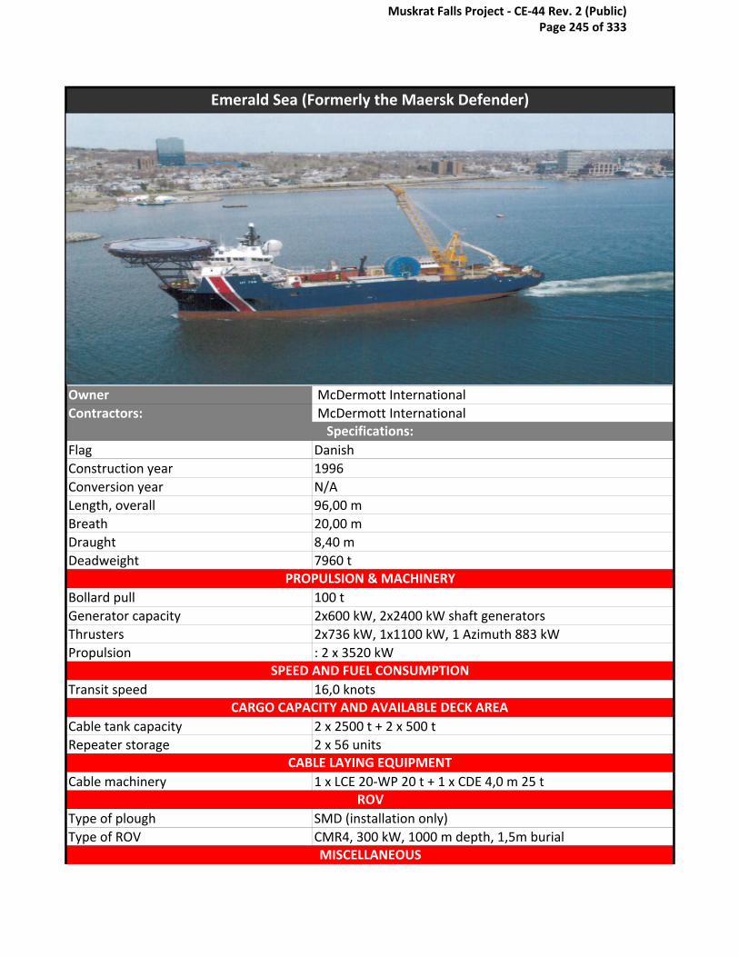
Owner McDermott International
Contractors: McDermott International
Flag Danish
Construction year 1996
Conversion year N/A
Length, overall 96,00 m
Breath 20,00 m
Draught 8,40 m
Deadweight 7960 t
Bollard pull 100 t
Generator capacity 2x600 kW, 2x2400 kW shaft generators
Thrusters 2x736 kW, 1x1100 kW, 1 Azimuth 883 kW
Propulsion : 2 x 3520 kW
Transit speed 16,0 knots
Cable tank capacity 2 x 2500 t + 2 x 500 t
Repeater storage 2 x 56 units
Cable machinery 1 x LCE 20-WP 20 t + 1 x CDE 4,0 m 25 t
Type of plough SMD (installation only)
Type of ROV CMR4, 300 kW, 1000 m depth, 1,5m burial
Emerald Sea (Formerly the Maersk Defender)
CABLE LAYING EQUIPMENT
ROV
MISCELLANEOUS
CARGO CAPACITY AND AVAILABLE DECK AREA
PROPULSION & MACHINERY
SPEED AND FUEL CONSUMPTION
Specifications:
Muskrat Falls Project - CE-44 Rev. 2 (Public) Page 245 of 333

Former cable lay ship, was purchased by Secunda (sub company of McDermott International in 2006
and converted to a subsea support ship. The ship has been upgraded in late 07 with additional living
quarters, moonpool, a helideck and a 100t subsea crane.
Muskrat Falls Project - CE-44 Rev. 2 (Public) Page 246 of 333

Giulio Verne
North Ocean 102
Muskrat Falls Project - CE-44 Rev. 2 (Public) Page 247 of 333

CS Global Sentinel and CS Teneo
Teliri
Muskrat Falls Project - CE-44 Rev. 2 (Public) Page 248 of 333

Emerald Sea
Muskrat Falls Project - CE-44 Rev. 2 (Public) Page 249 of 333

Team Oman
Skagerrak
Muskrat Falls Project - CE-44 Rev. 2 (Public) Page 250 of 333

M/V “ELEKTRON"
ASEAN Explorer
Muskrat Falls Project - CE-44 Rev. 2 (Public) Page 251 of 333

Muskrat Falls Project - CE-44 Rev. 2 (Public) Page 252 of 333

Stemat Spirit
Cable Innovator
Muskrat Falls Project - CE-44 Rev. 2 (Public) Page 253 of 333

CS Sovereign
ASEAN Restorer
Muskrat Falls Project - CE-44 Rev. 2 (Public) Page 254 of 333

Muskrat Falls Project - CE-44 Rev. 2 (Public) Page 255 of 333

*Statnett's M/V Electron was converted to Cable lay vessel in 2009
http://www.shipspotting.com/modules/myalbum/viewcat.php?pos=510&cid=38&num=10&orderby=hitsA
* From my research the six vessels listed are the most suitable from the job of installing the cable in SOBI
* Thought may also be given to Vessels of Global Marine's Fleet: CS Sovereign,Cable Innovator,Cable Networker (Barge), Wave Sentinel
* Thought may also be given to Tyco Telecommunications Fleet: CS Tyco Reliance,CS Tyco Responder
*Thought may be given to Ile De Batz, and Ile De Sein of Alcatel
Muskrat Falls Project - CE-44 Rev. 2 (Public) Page 256 of 333

http://www.shipspotting.com/modules/myalbum/viewcat.php?pos=510&cid=38&num=10&orderby=hitsA Intresting site
* From my research the six vessels listed are the most suitable from the job of installing the cable in SOBI
* Thought may also be given to Vessels of Global Marine's Fleet: CS Sovereign,Cable Innovator,Cable Networker (Barge), Wave Sentinel
* Thought may also be given to Tyco Telecommunications Fleet: CS Tyco Reliance,CS Tyco Responder,CS Tyco Resolute,CS Tyco Dependable,CS Tyco Decisive,CS Tyco Durable,CS Global
Muskrat Falls Project - CE-44 Rev. 2 (Public) Page 257 of 333

Muskrat Falls Project - CE-44 Rev. 2 (Public) Page 258 of 333

Appendix V- Skagerrak Information
Muskrat Falls Project - CE-44 Rev. 2 (Public) Page 259 of 333

Updated April 2010 Page 1 of 8 N - Nexans Skagerrak description
April 2010 extended.docx
C / S N E X A N S S K A G E R R A K
OWNER: NEXANS SKAGERRAK AS (A wholly-owned subsidiary of Nexans Norway AS)
NOTE. The vessel was extended 12.5 metres by mid April 2010. The vessel data has therefore been updated. GENERAL C/S NEXANS SKAGERRAK is specially built for laying and repair of heavy submarine power cables. The main features are the 7000 tonnes and 29 m diameter turntable and purpose designed cable laying gear based on a cable capstan and linear engine combination with a 5 m cable radius throughout. The fully redundant dynamic positioning system allows C/S NEXANS SKAGERRAK to operate close to offshore structures and perform accurate cable laying operations.
Muskrat Falls Project - CE-44 Rev. 2 (Public) Page 260 of 333
Updated April 2010 Page 2 of 8 N - Nexans Skagerrak description
April 2010 extended.docx
THE VESSEL GENERAL IMO NO: 7619458 Call sign LCEK CLASSIFICATION Classification society: DNV Class 1A1 MW. EO. Cable Laying Vessel
DYNPOS AUTR. Unrestricted trade DNV ERN 99.99.99 Flag Norwegian (NOR) THE HULL Gross Tons (GT): 7382 (ITC 69) Net Tons (NT): 2214 (ITC 69) DWT: 7150 Length of hull: - over all length: 112.25 m (368.2 ft.) - incl. laying sheave: 118.50 m (389.8 ft.) Total width: 32.15 m (105.5 ft.) Depth moulded: 8.00 m (26.2 ft) Draught at 7150 DWT.: 5.40 m (17.7 ft.) - incl. stern propellers: 6.17 m (20.2 ft.) - bow propeller lowered 8.13 m (26.7 ft.) Deck load: 10 tonnes/m2 Ballast capacity: 5948 tonnes Speed, approx.: 10 knots PROPULSION MACHINERY Stern thrusters: - steerable, port side: 1943 kW (2640 HP) - steerable, starb. side: 1943 kW (2640 HP) - steerable, center: 1000 kW (1360 HP) Bow thrusters: - steerable, center: 1820 kW (2475 HP) - tunnel: 957 kW (1300 HP) AUXILIARY ENGINES Motor generators: 380 V, 50 Hz Number of generators: 5
Muskrat Falls Project - CE-44 Rev. 2 (Public) Page 261 of 333

Updated April 2010 Page 3 of 8 N - Nexans Skagerrak description
April 2010 extended.docx
Capacity: 4 x 500 kVA
1 x 600 kVA
ACCOMMODATION FACILITIES Single berth cabins: 60 Double berth hospital: 1 Accommodation container(s): Option ELECTRONIC EQUIPMENT NAVIGATION EQUIPMENT Radar, 3 cm and 10 cm. Gyros Echo sounding equipment. Satellite navigation. Doppler log. Autopilot. SURFACE REFERENCE SYSTEMS Differential GPS Differential GPS/GLONASS IALA UHF Fanbeam UNDERWATER POSITION REFERENCE SYSTEM Kongsberg Simrad HIPAP 500 DYNAMIC POSITIONING EQUIPMENT Kongsberg Simrad SDP 521 NAVIGATION BACK-UP AND DATA LOGGING SYSTEM Fugro software. COMMUNICATION EQUIPMENT Marine Radio System. VHF-stations. Mobile VHF and UHF stations
for the cable operations.
Closed circuit TV-system.
Muskrat Falls Project - CE-44 Rev. 2 (Public) Page 262 of 333
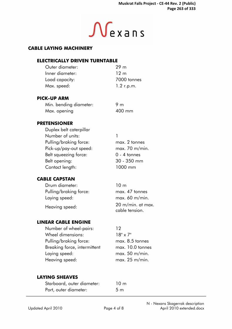
Updated April 2010 Page 4 of 8 N - Nexans Skagerrak description
April 2010 extended.docx
CABLE LAYING MACHINERY ELECTRICALLY DRIVEN TURNTABLE Outer diameter: 29 m Inner diameter: 12 m Load capacity: 7000 tonnes Max. speed: 1.2 r.p.m. PICK-UP ARM Min. bending diameter: 9 m Max. opening 400 mm PRETENSIONER Duplex belt caterpillar Number of units: 1 Pulling/braking force: max. 2 tonnes Pick-up/pay-out speed: max. 70 m/min. Belt squeezing force: 0 - 4 tonnes Belt opening: 30 - 350 mm Contact length: 1000 mm CABLE CAPSTAN Drum diameter: 10 m Pulling/braking force: max. 47 tonnes Laying speed: max. 60 m/min.
Heaving speed: 20 m/min. at max.
cable tension.
LINEAR CABLE ENGINE Number of wheel-pairs: 12 Wheel dimensions: 18" x 7" Pulling/braking force: max. 8.5 tonnes Breaking force, intermittent max. 10.0 tonnes Laying speed: max. 50 m/min. Heaving speed: max. 25 m/min. LAYING SHEAVES Starboard, outer diameter: 10 m Port, outer diameter: 5 m
Muskrat Falls Project - CE-44 Rev. 2 (Public) Page 263 of 333

Updated April 2010 Page 5 of 8 N - Nexans Skagerrak description
April 2010 extended.docx
CABLE REPAIR WINCH Low pressure hydraulic winches
with separate wire drums, for cable repair.
Number of units: 2 Wire dimension: 38 mm Wire length: 3000 m Pulling force: max. SWL 30 tonnes MOORING CAPSTANS Two speed electrically operated
capstans.
Number of units: 4 Pulling force: max. 10 tonnes each Low pressure hydraulic capstans
on forecastle.
Number of units: 2 Pulling force: 12 tonnes Speed: max. 42 m/min. MAIN ANCHOR WINCHES Number of units: 2 Pulling force: 12/20 tonnes each Length of chain: 550 m Anchor weight: 4.59 tonnes each CRANES HYDRAULIC CRANES ON CABLE REPAIR DECK Number of units: 3 Boom length: 16 m Lifting capacity: SWL 5 tonnes each A-FRAME Lifting capacity: SWL 40 tonnes OTHER CRANES
Lifting capacity: 20 tonnes on 16
metres
Muskrat Falls Project - CE-44 Rev. 2 (Public) Page 264 of 333
Updated April 2010 Page 6 of 8 N - Nexans Skagerrak description
April 2010 extended.docx
MISCELLANEOUS AUXILIARY EQUIPMENT
For a cable laying or a cable repair operation, C/S NEXANS SKAGERRAK can be equipped with the following auxiliary equipment: work boats. Subsea cable cutting and retrieving equipment Equipment for the cable testing and splicing operations. The vessel has her own stores of equipment needed for laying or recovery operations and a mechanical work-shop equipped for various types of metal processing and repair work.
ROV The vessel is equipped with a Remote Operated Vehicle (ROV) of type ARGUS
Mariner XL as standard, in order to monitor the cable touch down point on the seabed, perform subsea intervention tasks or execute pre- and post-lay surveys.
TRENCHING
The vessel can be used as support vessel for various subsea tasks including cable and flowline trenching operations using the CAPJET waterjet based trenching systems developed by Nexans Norway.
Muskrat Falls Project - CE-44 Rev. 2 (Public) Page 265 of 333
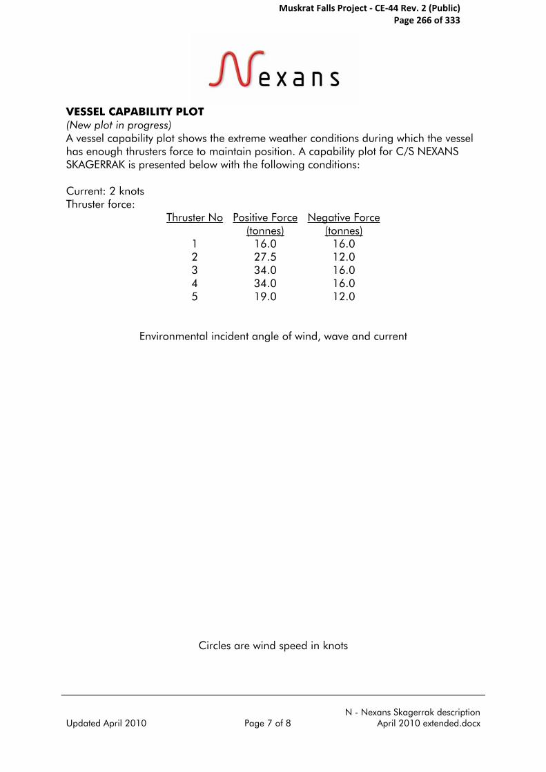
Updated April 2010 Page 7 of 8 N - Nexans Skagerrak description
April 2010 extended.docx
VESSEL CAPABILITY PLOT (New plot in progress) A vessel capability plot shows the extreme weather conditions during which the vessel has enough thrusters force to maintain position. A capability plot for C/S NEXANS SKAGERRAK is presented below with the following conditions: Current: 2 knots Thruster force:
Thruster No Positive Force (tonnes)
Negative Force (tonnes)
1 16.0 16.0 2 27.5 12.0 3 34.0 16.0 4 34.0 16.0 5 19.0 12.0
Environmental incident angle of wind, wave and current
Circles are wind speed in knots
Muskrat Falls Project - CE-44 Rev. 2 (Public) Page 266 of 333

Updated Nov 2008 Page 8 of 8 N - Nexans Skagerrak description April 2010
extended.docx
GENERAL ARRANGEMENT (Profile only)
Muskrat Falls Project - CE-44 Rev. 2 (Public) Page 267 of 333
Appendix W- Scanmudring SCANmaskin Specifications
Muskrat Falls Project - CE-44 Rev. 2 (Public) Page 268 of 333

Ballastgt. 3
NO-4515 Mandal
Tel.: +47 38 27 80 30
Fax: +47 38 27 80 39
www.scanmudring.no
The Scanmaskin tool-carrying systems are designed for implementing dredging, excavator, cutting, and various other hydraulically operated tools. They have been successfully deployed in many deep, shallow, harsh water, high current, and low visibility underwater construction activities such as:
• Subseaprecisionexcavationinconnectionwithrepairs,hot-tapping, pilecutting,andinspection• Levellingandmodificationofseabed (rockdump,hardandsoftclays,andsoils)• Rockdump,drillcut,boulder,anddebrisremoval/relocation• Pipelineandcabledeburial,maintenance,location,andinspection• Groutingremoval• Trenchingtasks• Assistanceandpreparationforinstallationanddecommissioning ofplatformsandsubseaassets• Nearshoreprograms(suchasprecisiondrillinginpreparation forblastingandHighVoltagecablerepair) The Scanmaskin subsea excavator and tool-carrier systems are based on modified excavators combined with state of the art ROV technologies with open tool interfaces. This combination harnesses the experience of both the advanced subsea technologies and the ruggedness of land based construction machines. The Scanmaskin systems are designed for rapid mobilisation and opetation in water depths up to 1000m. A special monitoring system (MoS), enables safer operation and improved productivity in poor visibility applications. This is most valuable when operating close to live assets or in projects requiring the combination of power and precision. The excavation capability in hard soil is excellent. Our hydraulic drum cutter has been successful tested on concrete slabs with hardness of about 15 MPa.
Precision subsea excavator and tool-carrier
Muskrat Falls Project - CE-44 Rev. 2 (Public) Page 269 of 333

This
doc
umen
t is
the
prop
erty
of S
canm
udrin
g A
S (r
ev.B
)
Ballastgt. 3, NO-4515 Mandal, Tel.: +47 38 27 80 30, Fax: +47 38 27 80 39, E-mail: [email protected]
www.scanmudring.no
TECHNICAL SPECIFICATION
GENERAL Name: Scanmaskin1000
Manufacturer: Scanmudring
Rov class: Norsok ROV class IV
Type: Tracked (bottom crawling) ROV system
Work capabilities: Subsea construction and excavation work
Available tools: 12”, 14”, and 16” suction ejector systems Excavator and and special hydraulic operated tools (bucket, gripper, water jet, drill, cutter, blower, drum cutter, back flush) Excavator monitoring system (MoS) for accurate levelling and construction work Several configurations of arms and undercarriages available
Number of available units: 3 operational Scanmaskin 1000 complete systems available in several set-ups
DIMENSIONS AND WEIGHT No.1 No.2 No.3
Length* (m): 7.2 11.0 8.5
Width (m): 2.2 3.1 2.4
Height (m): 3.3 5.7 3.3
Weight in air (ton): 11 20 13
Manipulator reach (m): 5.5 11.0 6.5/9.5
* Stated dimensions in storage position with manipulator folded and with standard ejector.
OPERATING PARAMETERS Operating depth (m): 5 - 1000 5 - 1000 5 - 1000
Relocation range: With standard ejector(rock) (m) 13 19 17 Drillcutting with exhaust hose (m) 13 + 50 19 + 50 17 + 50 With slurry pump (m): NA 200 200 Water capacity (m³/h): 1950 1950 1950 Max removal capacity (m³/h): 95** 95** 95**
Navigation: Cameras: BW/Colour/low light: 3/1/1 3/1/1 3/1/1 Gyro: 1 1 1 MoS (excavation monitoring system), Yes Yes Yes accuracy +/-5cm:
SHIPBOARD SUPPORT LARS lift capacity (ton): 25 35 25
Deck space requirements***: Wooden landing area (m): 10x10 10x15 10x10 Umbilical winch (m): 4.5x2.2 4.5x2.2 4.5x2.2 Number of 20’ containers: 2 2 3 Number of 10’ containers: N/A 1 N/A Number of Baskets: N/A 1 N/A Space for spares/suction hoses (m): 12x2 12x2 12x2
Power supply requirements: 265kW, 440V, 60Hz, 250-400A, depending on tools fitted
12kW, 220V, 60Hz, 32-63A, depending on ambient temperature
Operators: 6 operators for 24hours operation supplied by Scanmudring.
** The removal capacity is heavily dependant on soil characteristics, ejector/pump sizes, and the operation conditions present at site. As a guideline about 5 per cent mixtures in water is possible when using the 12” to 16” ejectors, but the actual achieved capacity is normally lower. For project estimates a general removal capacity about 2-3 per cent should be expected. In order to achieve an efficient capacity, it is recommended to use an ejectors size about twice the average size of the items to be relocated.
*** Subject to system tool and project configuration. Different umbilical winches and container spreads will have an effect.
Muskrat Falls Project - CE-44 Rev. 2 (Public) Page 270 of 333

Appendix X- Cutting Grapnel
Muskrat Falls Project - CE-44 Rev. 2 (Public) Page 271 of 333

Global Marine Systems Limited New Saxon House 1 Winsford Way
Boreham Interchange Chelmsford Essex CM2 5PD
www.globalmarinesystems.com
Cutting Grapnel Asset no. GA 2-1 and 2-2
Cable Types: - Lightweight and Armoured Cable Up to 100mm Diameter Grapnel Dimensions: - Length 2.8m Width 1.12m Height 1.0m Weight 1.85 Tonnes Maximum Operating Depth 2000 Fathoms (3657m) Operating Temperature Minus 5C to + 50C Storage Temperature Minus 40C to + 50C Power Pack Dimensions: - Length 1.0m Width 0.8m Height 1.2m Weight 1.0 Tonne Power Supply 3 Phase, 415V, 50 Hz Oil Type Tellus 32 Gas Type Oxygen Free Nitrogen Acoustic Receiver 114 or Equivalent Pinger 138 or Equivalent
Muskrat Falls Project - CE-44 Rev. 2 (Public) Page 272 of 333

Global Marine Systems Limited New Saxon House 1 Winsford Way
Boreham Interchange Chelmsford Essex CM2 5PD
www.globalmarinesystems.com
Muskrat Falls Project - CE-44 Rev. 2 (Public) Page 273 of 333
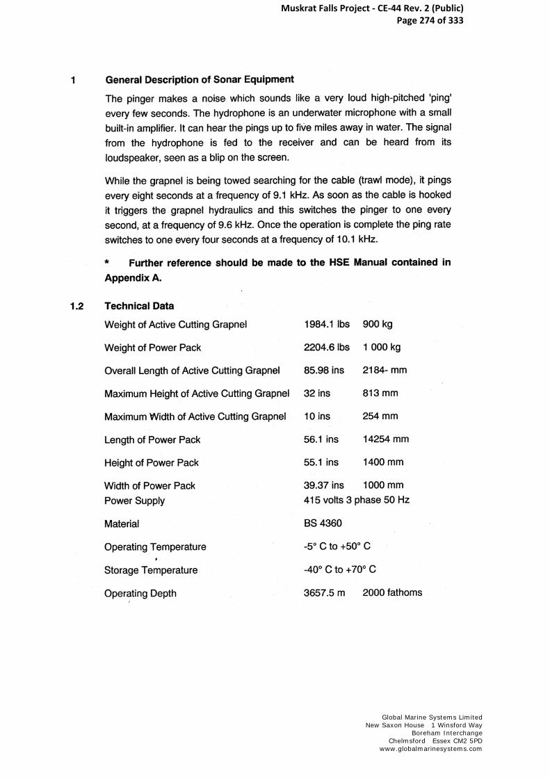
Global Marine Systems Limited New Saxon House 1 Winsford Way
Boreham Interchange Chelmsford Essex CM2 5PD
www.globalmarinesystems.com
Muskrat Falls Project - CE-44 Rev. 2 (Public) Page 274 of 333

Appendix Y- Nexans Skagerrak Cable Repair Specifications
Muskrat Falls Project - CE-44 Rev. 2 (Public) Page 275 of 333
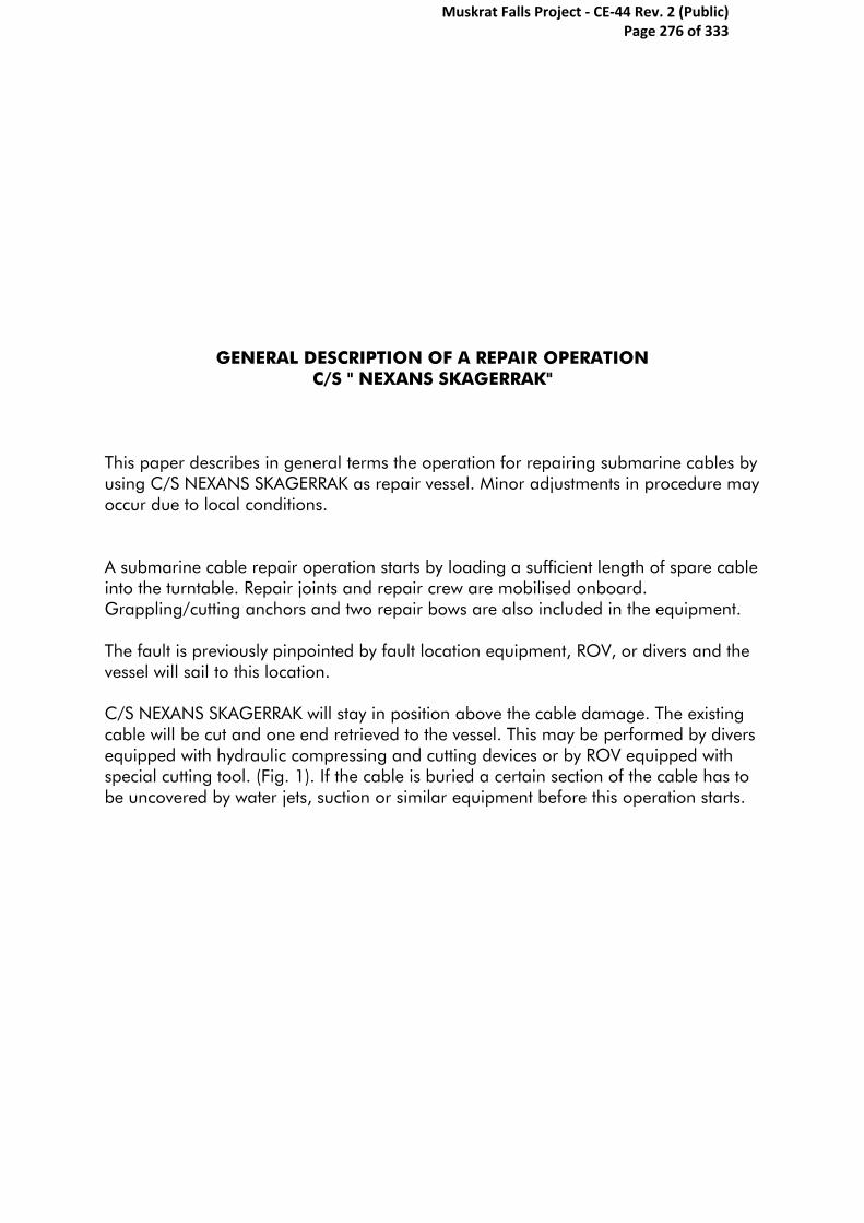
GENERAL DESCRIPTION OF A REPAIR OPERATION C/S " NEXANS SKAGERRAK"
This paper describes in general terms the operation for repairing submarine cables by using C/S NEXANS SKAGERRAK as repair vessel. Minor adjustments in procedure may occur due to local conditions. A submarine cable repair operation starts by loading a sufficient length of spare cable into the turntable. Repair joints and repair crew are mobilised onboard. Grappling/cutting anchors and two repair bows are also included in the equipment. The fault is previously pinpointed by fault location equipment, ROV, or divers and the vessel will sail to this location. C/S NEXANS SKAGERRAK will stay in position above the cable damage. The existing cable will be cut and one end retrieved to the vessel. This may be performed by divers equipped with hydraulic compressing and cutting devices or by ROV equipped with special cutting tool. (Fig. 1). If the cable is buried a certain section of the cable has to be uncovered by water jets, suction or similar equipment before this operation starts.
Muskrat Falls Project - CE-44 Rev. 2 (Public) Page 276 of 333

Fig. 1
It is essential that the ends of a paper insulated oil filled cable are properly compressed in order to minimise the oil leakage to the sea. In addition the winch wire is attached to the cable a certain distance from the cable end. During heaving the cable end is pointing downwards ("swan neck"). A winch wire is positioned through the caterpillar linear tensioner, the capstan and the linear cable laying machine. This wire is connected to the grappling anchor or to a cable clamp on the cable. The cable end is carefully brought to the surface as the vessel moves slowly backwards along the original route. The cable end is carefully pulled in over the cable laying wheel, through the linear cable laying machine, over the capstan and through the caterpillar linear machine. During the recovery operation the cable is visually inspected, and damaged cable is cut on the turntable. The cable end is then sealed and lowered down to the seabed with a steel wire connected to a surface buoy, for later recovery.
Muskrat Falls Project - CE-44 Rev. 2 (Public) Page 277 of 333
The other end of the cable is now being recovered and brought up to the vessel following the same procedure as for the first end. Damaged cable is cut on the turntable. While the cable end is still in the cable guide above the turntable the spare cable is pulled on guides from the turntable through the repair deck on starboard side, around the repair bow (at the stern) up to the jointing room located at the port side of the vessel. The cable end is secured in the jointing room. (Fig. 2 & 3).
Fig. 2 Fig. 3
Muskrat Falls Project - CE-44 Rev. 2 (Public) Page 278 of 333

The recovered cable is pulled around the turntable and into the repair room as C/S NEXANS SKAGERRAK recovers more cable while moving backwards. The operation stops when the cable end has reached the repair room. The cable is secured. (Fig. 4).
Fig. 4
The first cable joint between spare cable and existing cable is performed by skilled jointers. The jointing method depends upon the type of cable. During the jointing work C/S NEXANS SKAGERRAK stays in position by DP. Finishing the jointing work all supports that keep the repair bow in position, is released. The laying operation will commence, and the tension in the cable will pull the repair bow forwards. The operation stops when the bow has reached its end position nearby the turntable. The repair bow is lifted up and removed. All spare cable and the first repair joint are now placed on the turntable. (Fig. 5).
Muskrat Falls Project - CE-44 Rev. 2 (Public) Page 279 of 333

Fig. 5
C/S NEXANS SKAGERRAK continues to lay the cable along the original route until the vessel reaches the position above the second end of the existing cable. The second cable end is retrieved. C/S NEXANS SKAGERRAK moves slowly forwards along the route and pays out more spare cable while the second end of the existing cable is carefully being pulled on board over the repair sheave. The operation stops when undamaged cable has reached the repair room and been secured. The spare cable is cut and the ends sealed. The spare cable is paid out until the end has passed through the caterpillar linear machine and the cable capstan. The cable is pulled through roller guides from the linear tensioning machine and pulled over the repair bow (now located nearby the turntable) and back into the repair room. The cable end is secured. Both cables are now secured at the stern laying wheel and stern repair sheave respectively. (Fig. 6).
Muskrat Falls Project - CE-44 Rev. 2 (Public) Page 280 of 333

Fig. 6
The second joint between spare cable and existing cable is now being performed. During the jointing work C/S NEXANS SKAGERRAK stays in position by DP. When the second joint is finished the securing locks at the stern laying wheel and stern repair sheave are removed. The winch wire attached to the repair bow is slacken. The cable is laid out over the wheel and sheave while C/S NEXANS SKAGERRAK is moving slowly perpendicular to the cable route. The tension in the cable will move the repair bow toward the stern as the winch wire is slacken away. The operation stops temporary when the repair bow has reached the aft part of the repair deck. (Fig. 7).
Muskrat Falls Project - CE-44 Rev. 2 (Public) Page 281 of 333
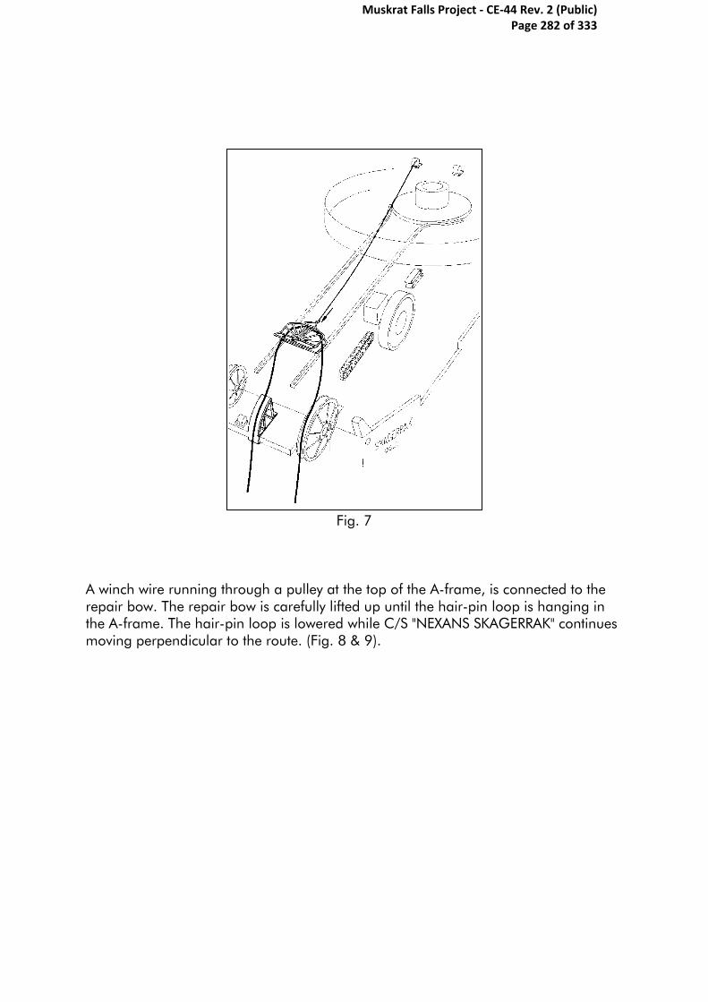
Fig. 7
A winch wire running through a pulley at the top of the A-frame, is connected to the repair bow. The repair bow is carefully lifted up until the hair-pin loop is hanging in the A-frame. The hair-pin loop is lowered while C/S "NEXANS SKAGERRAK" continues moving perpendicular to the route. (Fig. 8 & 9).
Muskrat Falls Project - CE-44 Rev. 2 (Public) Page 282 of 333
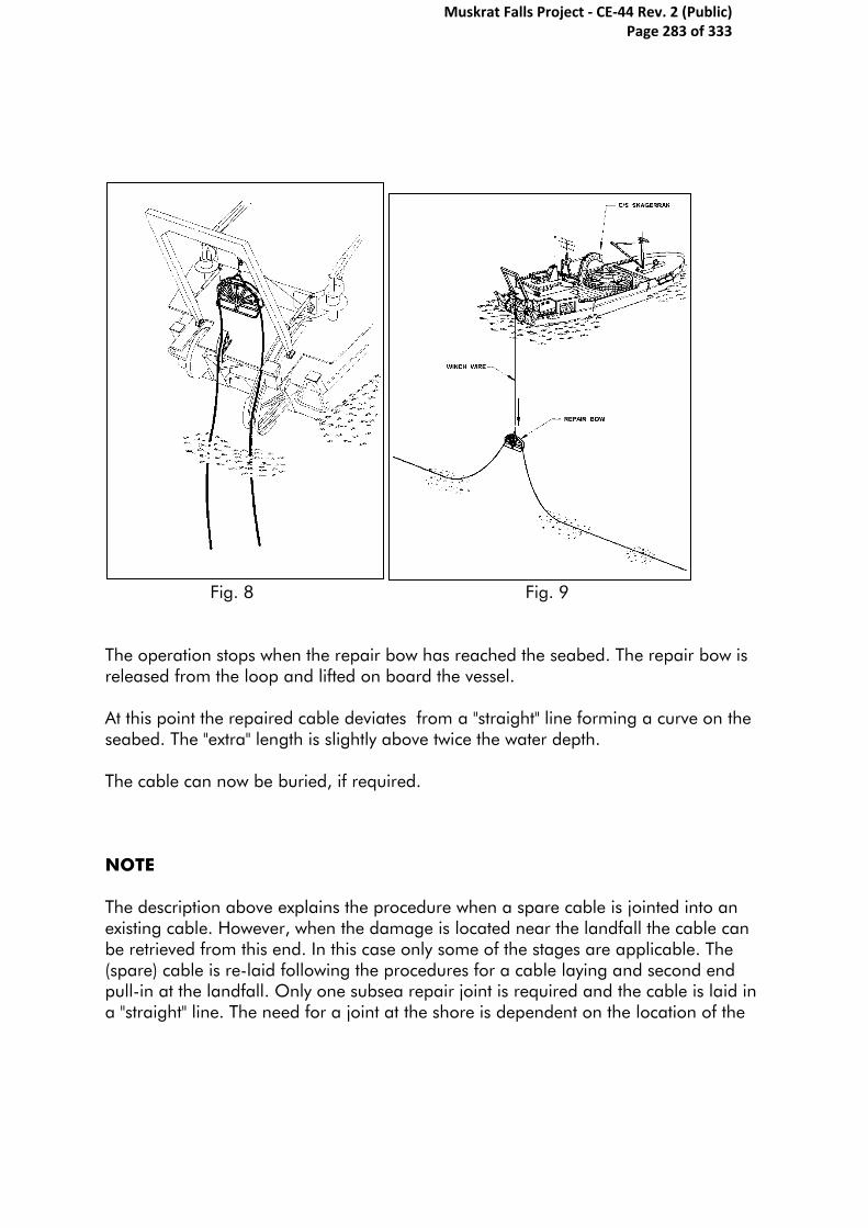
Fig. 8 Fig. 9
The operation stops when the repair bow has reached the seabed. The repair bow is released from the loop and lifted on board the vessel. At this point the repaired cable deviates from a "straight" line forming a curve on the seabed. The "extra" length is slightly above twice the water depth. The cable can now be buried, if required. NOTE The description above explains the procedure when a spare cable is jointed into an existing cable. However, when the damage is located near the landfall the cable can be retrieved from this end. In this case only some of the stages are applicable. The (spare) cable is re-laid following the procedures for a cable laying and second end pull-in at the landfall. Only one subsea repair joint is required and the cable is laid in a "straight" line. The need for a joint at the shore is dependent on the location of the
Muskrat Falls Project - CE-44 Rev. 2 (Public) Page 283 of 333

termination. If located near the shore the spare cable will replace the previous laid cable from the subsea joint to the termination. Operational limits during jointing The operations are based on weather conditions not exceeding the following parameters given below. However, the values are guidelines only. The Captain and the Operation Manager will evaluate the weather conditions on site and act accordingly. The direction of wind and current resulting sea state might give other values. Retrieve cable end Jointing operation Laying the joint Wind force: 12 m/s
(23 knots) 15 m/s
(29 knots) 12 m/s
(23 knots) Max. wave height: 3.5 m 5 m 3.5 m Current, surface: 1.3 m/s
(2.5 knots) 1.3 m/s
(2.5 knots 1.3 m/s
(2.5 knots Current, bottom: 1.3 m/s
(2.5 knots N/A 1.3 m/s
(2.5 knots Surface visibility: N/A N/A N/A Visibility in water: 2 m N/A 2 m
Muskrat Falls Project - CE-44 Rev. 2 (Public) Page 284 of 333
Appendix Z- SOBI Seabed Installation Schedule
Muskrat Falls Project - CE-44 Rev. 2 (Public) Page 285 of 333
Activity ID Activity Name Start Finish
SOBI Seabed InstallationSOBI Seabed InstallationSOBI Seabed InstallationSOBI Seabed InstallationSOBI_IL_0011150 INSTALLATION START MILESTONE 27-May-13*
SOBI_IL_0011170 SOBI CONTRACT CABLE INSTALLATION START (VESSELS 'IN' WATER) 01-Jun-15*
SOBI_IL_0011110 COMPLETIONS MILESTONE 19-Sep-15
CONTRACTINGCONTRACTINGCONTRACTINGCONTRACTING
CABLE SUPPLY & INSTALLCABLE SUPPLY & INSTALLCABLE SUPPLY & INSTALLCABLE SUPPLY & INSTALL
SOBI_IL_0012550 Bid, Evaluate, and Award 04-Jan-11* 16-Dec-11
SOBI_IL_0013400 Vendor Engineering 03-Jan-12 14-Dec-12
SOBI_IL_0013410 Vendor Fabrication 17-Dec-12* 06-Dec-13
SOBI_IL_0013430 Completion Milestone 06-Dec-13
ROCK BERM CONSTRUCTION (INCL. SUPPLY)ROCK BERM CONSTRUCTION (INCL. SUPPLY)ROCK BERM CONSTRUCTION (INCL. SUPPLY)ROCK BERM CONSTRUCTION (INCL. SUPPLY)
SOBI_IL_0013380 Bid, Evaluate & Award - (Contractor Supply & Install) 23-Jul-12* 24-Jan-13
HORIZONTAL DIRECTIONAL DRILLINGHORIZONTAL DIRECTIONAL DRILLINGHORIZONTAL DIRECTIONAL DRILLINGHORIZONTAL DIRECTIONAL DRILLING
SOBI_IL_0013370 Bid, Evaluate, and Award - Engineering 01-Nov-11* 03-May-12
SOBI_IL_0012730 Engineering 04-May-12 25-Mar-13
SOBI_IL_0013390 Bid, Evaluate, & Award HDD Contractor 26-Mar-13 22-Jul-13
LEVELINGLEVELINGLEVELINGLEVELING
MOB.MOB.MOB.MOB.
SOBI_IL_0011310 Vessel loadout 26-Jun-14* 26-Jun-14
SOBI_IL_0011900 VESSEL ARRIVAL IN NL 26-Jun-14*
SOBI_IL_0011010 Bunkering 26-Jun-14* 27-Jun-14
SOBI_IL_0011020 Equipment Loadout 27-Jun-14 27-Jun-14
SOBI_IL_0011030 Personnel Change 27-Jun-14 28-Jun-14
ExecutionExecutionExecutionExecution
Trip 1Trip 1Trip 1Trip 1
SOBI_IL_0011340 Transit 28-Jun-14 28-Jun-14
SOBI_IL_0011050 PreSurvey 28-Jun-14* 29-Jun-14
SOBI_IL_0011060 Rock Laying 29-Jun-14 29-Jun-14
SOBI_IL_0011510 Transit 29-Jun-14 30-Jun-14
Trip 2Trip 2Trip 2Trip 2
SOBI_IL_0011490 Vessel Loadout 30-Jun-14 30-Jun-14
SOBI_IL_0011520 Transit 30-Jun-14 30-Jun-14
SOBI_IL_0011470 Rock Laying 30-Jun-14 01-Jul-14
SOBI_IL_0011070 Post Survey 01-Jul-14 01-Jul-14
SOBI_IL_0011530 Transit 01-Jul-14 01-Jul-14
DE-MOB.DE-MOB.DE-MOB.DE-MOB.
J F A J J A S N D J F A J J A S N J F A J J A S D J F A J J A S N J F A J J A S D J F A J J A S D J F
2011 2012 2013 2014 2015 2016 2017
INSTALLATION START MILESTONE
SOBI CONTRACT CABLE INSTALLATION START (VESSELS 'IN' WATER)
COMPLETIONS MILESTONE
Completion Milestone
VESSEL ARRIVAL IN NL
Nalcor Energy - Lower Churchill Project
SOBI SEABED INSTALLATION SCHEDULE
Layout: SOBI Seabed Installation Schedule
TASK filter: PWP: Scope Package Selector_2.
Printed: 26-Nov-10
Remaining Work
Critical Remaining Work
Remaining Level of Effort
Milestone
UDF Baseline MS
UDF Baseline
% Complete Page 1 of 8 File: SOBI...
Baseline:
Data Date: 01-Jan-11
Date Revision Checked Approved
Muskrat Falls Project - CE-44 Rev. 2 (Public) Page 286 of 333

Activity ID Activity Name Start Finish
SOBI_IL_0011080 Equipment Offload 01-Jul-14 02-Jul-14
HDD (Horizontal Directional Drilling)HDD (Horizontal Directional Drilling)HDD (Horizontal Directional Drilling)HDD (Horizontal Directional Drilling)
SOBI_IL_0011600 Pre-Works for HDD 22-Jul-13 21-Aug-13
NL SideNL SideNL SideNL Side
Hole for Cable 1Hole for Cable 1Hole for Cable 1Hole for Cable 1
SOBI_IL_0011420 Mobilization 21-Aug-13 10-Sep-13
SOBI_IL_0011120 Rigging Drill Rig - Hole 1 10-Sep-13 10-Oct-13
SOBI_IL_0011130 Drilling Hole - Hole 1 10-Oct-13 17-Feb-14
Hole for Cable 2Hole for Cable 2Hole for Cable 2Hole for Cable 2
SOBI_IL_0011210 Rigging Drill Rig - Hole 2 17-Feb-14 19-Mar-14
SOBI_IL_0011250 Drilling Hole - Hole 2 19-Mar-14 27-Jul-14
Hole for Cable 3Hole for Cable 3Hole for Cable 3Hole for Cable 3
SOBI_IL_0011220 Rigging Drill Rig - Hole 3 27-Jul-14 16-Aug-14
SOBI_IL_0011240 Drilling Hole - Hole 3 16-Aug-14 24-Dec-14
SOBI_IL_0011260 De-Mob. - Hole 3 24-Dec-14 03-Jan-15
SOBI_IL_0011430 DRILLING PROGRAM COMPLETION, NL SIDE 04-Jan-15
Labrador SideLabrador SideLabrador SideLabrador Side
Hole for Cable 1Hole for Cable 1Hole for Cable 1Hole for Cable 1
SOBI_IL_0011620 Mobilization 21-Aug-13 10-Sep-13
SOBI_IL_0011270 Rigging Drill Rig - Hole 1 10-Sep-13 10-Oct-13
SOBI_IL_0011580 Drilling Holes - Hole 1 10-Oct-13 17-Feb-14
Hole for Cable 2Hole for Cable 2Hole for Cable 2Hole for Cable 2
SOBI_IL_0011630 Rigging Drill Rig - Hole 1 17-Feb-14 19-Mar-14
SOBI_IL_0011650 Drilling Holes - Hole 1 19-Mar-14 27-Jul-14
Hole for Cable 3Hole for Cable 3Hole for Cable 3Hole for Cable 3
SOBI_IL_0011750 Rigging Drill Rig - Hole 1 27-Jul-14 16-Aug-14
SOBI_IL_0011820 Drilling Holes - Hole 1 16-Aug-14 24-Dec-14
SOBI_IL_0011830 De-Mob. - Hole 1 24-Dec-14 03-Jan-15
SOBI_IL_0011450 DRILLING PROGRAM COMPLETION, LAB. SIDE 04-Jan-15
ROCK SUPPLY / CRUSHINGROCK SUPPLY / CRUSHINGROCK SUPPLY / CRUSHINGROCK SUPPLY / CRUSHING
SOBI_IL_0011140 Rock Crushing (Initial Leveling campaign) 17-May-14 16-Jun-14
SOBI_IL_0011040 Rock Crushing (for Rock dumping campaign) 09-Oct-14* 19-Sep-15
TRANSITION COMPOUNDSTRANSITION COMPOUNDSTRANSITION COMPOUNDSTRANSITION COMPOUNDS
SOBI_IL_0011090 Transition Compounds (Before HDD) 03-Jun-13* 13-Jun-13
SOBI_IL_0011100 Transition Compounds (After Rock Dumping) 31-Jul-15 16-Nov-15
CABLE INSTALLATIONCABLE INSTALLATIONCABLE INSTALLATIONCABLE INSTALLATION
SOBI_IL_0011320 CABLE INSTALLATION START MILESTONE 01-Apr-15*
EURO MOB.EURO MOB.EURO MOB.EURO MOB.
SOBI_IL_0011730 Transit to Factory 01-Apr-15 04-Apr-15
SOBI_IL_0011740 Loading at factory 04-Apr-15 14-Apr-15
SOBI_IL_0011640 Transit to NL 14-Apr-15 23-Apr-15
J F A J J A S N D J F A J J A S N J F A J J A S D J F A J J A S N J F A J J A S D J F A J J A S D J F
2011 2012 2013 2014 2015 2016 2017
DRILLING PROGRAM COMPLETION, NL SIDE
DRILLING PROGRAM COMPLETION, LAB. SIDE
CABLE INSTALLATION START MILESTONE
Remaining Work
Critical Remaining Work
Remaining Level of Effort
Milestone
UDF Baseline MS
UDF Baseline
% Complete Page 2 of 8 File: SOBI...
Baseline:
Data Date: 01-Jan-11
Date Revision Checked Approved
Muskrat Falls Project - CE-44 Rev. 2 (Public) Page 287 of 333

Activity ID Activity Name Start Finish
NL MOB.NL MOB.NL MOB.NL MOB.
SOBI_IL_0011160 Bunkering 23-Apr-15 25-Apr-15
SOBI_IL_0011180 Equipment Transfer 25-Apr-15 26-Apr-15
SOBI_IL_0011680 Personnel Change 26-Apr-15 27-Apr-15
Additional Prep. WorkAdditional Prep. WorkAdditional Prep. WorkAdditional Prep. Work
SOBI_IL_0011230 Transit 27-Apr-15 29-Apr-15
SOBI_IL_0011200 Pre-Survey 31-May-15 01-Jun-15*
LevelingLevelingLevelingLeveling
SOBI_IL_0011280 Matressing 01-Jun-15 01-Jun-15
SOBI_IL_0011290 Sandbagging 01-Jun-15 02-Jun-15
EXECUTIONEXECUTIONEXECUTIONEXECUTION
Cable 1Cable 1Cable 1Cable 1
SOBI_IL_0011300 Cable Pull-in, Side 1 03-Jun-15 05-Jun-15
SOBI_IL_0011330 Cable Laying 05-Jun-15 06-Jun-15
SOBI_IL_0011400 Cable Abandonment at join location 06-Jun-15 06-Jun-15
SOBI_IL_0011920 Cable pull side 2 06-Jun-15 08-Jun-15
SOBI_IL_0012020 Cable laying 08-Jun-15 10-Jun-15
SOBI_IL_0012500 Cable recovery 10-Jun-15 10-Jun-15
SOBI_IL_0011930 Cable join 10-Jun-15 16-Jun-15
SOBI_IL_0011690 Testing 14-Jun-15 17-Jun-15
SOBI_IL_0011940 Cable abandon 16-Jun-15 17-Jun-15
SOBI_IL_0011700 Surveying 17-Jun-15 17-Jun-15
Cable 2Cable 2Cable 2Cable 2
SOBI_IL_0011350 Cable Pull-in, Side 1 17-Jun-15 19-Jun-15
SOBI_IL_0011360 Cable Laying 19-Jun-15 20-Jun-15
SOBI_IL_0011390 Cable Abandonment at join location 20-Jun-15 21-Jun-15
SOBI_IL_0011960 Cable pull-in side 2 21-Jun-15 23-Jun-15
SOBI_IL_0011970 Cable laying 23-Jun-15 24-Jun-15
SOBI_IL_0011980 Cable recovery 24-Jun-15 24-Jun-15
SOBI_IL_0012510 Cable join 24-Jun-15 01-Jul-15
SOBI_IL_0011370 Testing 28-Jun-15 01-Jul-15
SOBI_IL_0012520 Cable abandon 01-Jul-15 01-Jul-15
SOBI_IL_0011710 Surveying 01-Jul-15 02-Jul-15
Cable 3Cable 3Cable 3Cable 3
SOBI_IL_0011440 Cable Pull-in, Side 1 02-Jul-15 04-Jul-15
SOBI_IL_0011660 Cable Laying 04-Jul-15 05-Jul-15
SOBI_IL_0011410 Cable Abandonment at join location 05-Jul-15 05-Jul-15
SOBI_IL_0011990 Cable pull-in side 2 05-Jul-15 07-Jul-15
SOBI_IL_0012000 Cable laying 07-Jul-15 09-Jul-15
SOBI_IL_0012010 Cable recovery 09-Jul-15 09-Jul-15
SOBI_IL_0012530 Cable join 09-Jul-15 16-Jul-15
SOBI_IL_0011670 Testing 13-Jul-15 16-Jul-15
SOBI_IL_0012540 Cable abandon 16-Jul-15 16-Jul-15
SOBI_IL_0011720 Surveying 16-Jul-15 16-Jul-15
J F A J J A S N D J F A J J A S N J F A J J A S D J F A J J A S N J F A J J A S D J F A J J A S D J F
2011 2012 2013 2014 2015 2016 2017
Remaining Work
Critical Remaining Work
Remaining Level of Effort
Milestone
UDF Baseline MS
UDF Baseline
% Complete Page 3 of 8 File: SOBI...
Baseline:
Data Date: 01-Jan-11
Date Revision Checked Approved
Muskrat Falls Project - CE-44 Rev. 2 (Public) Page 288 of 333

Activity ID Activity Name Start Finish
SOBI_IL_0011770 Transit 16-Jul-15 17-Jul-15
SOBI_IL_0011780 NL De-MOB. 17-Jul-15 19-Jul-15
SOBI_IL_0011790 Transit 19-Jul-15 26-Jul-15
SOBI_IL_0011800 Equipment Load-out 26-Jul-15 28-Jul-15
SOBI_IL_0011810 Transit from Factory 28-Jul-15 31-Jul-15
Cable InstallationCable InstallationCable InstallationCable Installation
SOBI_IL_0011950 CABLE INSTALLATION COMPLETE 31-Jul-15
ROCK BERMROCK BERMROCK BERMROCK BERM
Rock Laying (Vessel#1)- (Trips, approx. 17,500 t/load)Rock Laying (Vessel#1)- (Trips, approx. 17,500 t/load)Rock Laying (Vessel#1)- (Trips, approx. 17,500 t/load)Rock Laying (Vessel#1)- (Trips, approx. 17,500 t/load)
MOB.MOB.MOB.MOB.
SOBI_IL_0011480 Personnel Change 08-Jun-15* 08-Jun-15
SOBI_IL_0011540 Equipment Loadout 08-Jun-15 08-Jun-15
SOBI_IL_0011550 Rock Loading (L1) 08-Jun-15* 09-Jun-15
SOBI_IL_0011910 VESSEL ARRIVAL TO NL 08-Jun-15*
Load 1Load 1Load 1Load 1
SOBI_IL_0012030 Transit 08-Jun-15 09-Jun-15
SOBI_IL_0012040 Rock laying 17-Jun-15 18-Jun-15
SOBI_IL_0012570 Transit 18-Jun-15 19-Jun-15
Load 2Load 2Load 2Load 2
SOBI_IL_0012050 Rock Loading (L2) 19-Jun-15 20-Jun-15
SOBI_IL_0012060 Transit 20-Jun-15 21-Jun-15
SOBI_IL_0012070 Rock laying 21-Jun-15 22-Jun-15
SOBI_IL_0012580 Transit 22-Jun-15 23-Jun-15
Load 3Load 3Load 3Load 3
SOBI_IL_0012080 Rock Loading (L3) 25-Jun-15 26-Jun-15
SOBI_IL_0012090 Transit 26-Jun-15 27-Jun-15
SOBI_IL_0012100 Rock laying 27-Jun-15 28-Jun-15
SOBI_IL_0012590 Transit 28-Jun-15 29-Jun-15
Load 4Load 4Load 4Load 4
SOBI_IL_0012110 Rock Loading (L4) 01-Jul-15 02-Jul-15
SOBI_IL_0012120 Transit 02-Jul-15 03-Jul-15
SOBI_IL_0012130 Rock laying 03-Jul-15 04-Jul-15
SOBI_IL_0012600 Transit 04-Jul-15 05-Jul-15
Load 5Load 5Load 5Load 5
SOBI_IL_0012140 Rock Loading (L5) 07-Jul-15 08-Jul-15
SOBI_IL_0012150 Transit 08-Jul-15 09-Jul-15
SOBI_IL_0012160 Rock laying 09-Jul-15 10-Jul-15
SOBI_IL_0012610 Transit 10-Jul-15 11-Jul-15
Load 6Load 6Load 6Load 6
SOBI_IL_0012170 Rock Loading (L6) 13-Jul-15 14-Jul-15
SOBI_IL_0012180 Transit 14-Jul-15 15-Jul-15
SOBI_IL_0012190 Rock laying 15-Jul-15 16-Jul-15
SOBI_IL_0012620 Transit 16-Jul-15 17-Jul-15
Load 7Load 7Load 7Load 7
SOBI_IL_0012200 Rock Loading (L7) 19-Jul-15 20-Jul-15
J F A J J A S N D J F A J J A S N J F A J J A S D J F A J J A S N J F A J J A S D J F A J J A S D J F
2011 2012 2013 2014 2015 2016 2017
CABLE INSTALLATION COMPLETE
VESSEL ARRIVAL TO NL
Remaining Work
Critical Remaining Work
Remaining Level of Effort
Milestone
UDF Baseline MS
UDF Baseline
% Complete Page 4 of 8 File: SOBI...
Baseline:
Data Date: 01-Jan-11
Date Revision Checked Approved
Muskrat Falls Project - CE-44 Rev. 2 (Public) Page 289 of 333

Activity ID Activity Name Start Finish
SOBI_IL_0012210 Transit 20-Jul-15 21-Jul-15
SOBI_IL_0012220 Rock laying 21-Jul-15 22-Jul-15
SOBI_IL_0012630 Transit 22-Jul-15 23-Jul-15
Load 8Load 8Load 8Load 8
SOBI_IL_0012230 Rock Loading (L8) 25-Jul-15 26-Jul-15
SOBI_IL_0012240 Transit 26-Jul-15 27-Jul-15
SOBI_IL_0012250 Rock laying 27-Jul-15 28-Jul-15
SOBI_IL_0012640 Transit 28-Jul-15 29-Jul-15
Load 9Load 9Load 9Load 9
SOBI_IL_0012260 Rock Loading (L9) 31-Jul-15 01-Aug-15
SOBI_IL_0012270 Transit 01-Aug-15 02-Aug-15
SOBI_IL_0012280 Rock laying 02-Aug-15 03-Aug-15
SOBI_IL_0012650 Transit 03-Aug-15 04-Aug-15
Load 10Load 10Load 10Load 10
SOBI_IL_0012290 Rock Loading (L10) 06-Aug-15 07-Aug-15
SOBI_IL_0012300 Transit 07-Aug-15 08-Aug-15
SOBI_IL_0012310 Rock laying 08-Aug-15 09-Aug-15
SOBI_IL_0012660 Transit 09-Aug-15 10-Aug-15
Load 11Load 11Load 11Load 11
SOBI_IL_0012320 Rock Loading (L11) 12-Aug-15 13-Aug-15
SOBI_IL_0012330 Transit 13-Aug-15 14-Aug-15
SOBI_IL_0012340 Rock laying 14-Aug-15 15-Aug-15
SOBI_IL_0012670 Transit 15-Aug-15 16-Aug-15
Load 12Load 12Load 12Load 12
SOBI_IL_0012350 Rock Loading (L12) 18-Aug-15 19-Aug-15
SOBI_IL_0012360 Transit 19-Aug-15 20-Aug-15
SOBI_IL_0012370 Rock laying 20-Aug-15 21-Aug-15
SOBI_IL_0012680 Transit 21-Aug-15 22-Aug-15
Load 13Load 13Load 13Load 13
SOBI_IL_0012380 Rock Loading (L13) 24-Aug-15 25-Aug-15
SOBI_IL_0012390 Transit 25-Aug-15 26-Aug-15
SOBI_IL_0012400 Rock laying 26-Aug-15 27-Aug-15
SOBI_IL_0012690 Transit 27-Aug-15 28-Aug-15
Load 14Load 14Load 14Load 14
SOBI_IL_0012410 Rock Loading (L14) 30-Aug-15 31-Aug-15
SOBI_IL_0012420 Transit 31-Aug-15 01-Sep-15
SOBI_IL_0012430 Rock laying 01-Sep-15 02-Sep-15
SOBI_IL_0012700 Transit 02-Sep-15 03-Sep-15
Load 15Load 15Load 15Load 15
SOBI_IL_0012440 Rock Loading (L15) 07-Sep-15 08-Sep-15
SOBI_IL_0012450 Transit 08-Sep-15 09-Sep-15
SOBI_IL_0012460 Rock laying 09-Sep-15 10-Sep-15
SOBI_IL_0012710 Transit 10-Sep-15 11-Sep-15
Load 16Load 16Load 16Load 16
SOBI_IL_0012470 Rock Loading (L16) 13-Sep-15 14-Sep-15
J F A J J A S N D J F A J J A S N J F A J J A S D J F A J J A S N J F A J J A S D J F A J J A S D J F
2011 2012 2013 2014 2015 2016 2017
Remaining Work
Critical Remaining Work
Remaining Level of Effort
Milestone
UDF Baseline MS
UDF Baseline
% Complete Page 5 of 8 File: SOBI...
Baseline:
Data Date: 01-Jan-11
Date Revision Checked Approved
Muskrat Falls Project - CE-44 Rev. 2 (Public) Page 290 of 333
Activity ID Activity Name Start Finish
SOBI_IL_0012480 Transit 14-Sep-15 15-Sep-15
SOBI_IL_0012490 Rock laying 15-Sep-15 16-Sep-15
SOBI_IL_0012720 Transit 16-Sep-15 17-Sep-15
Post SurveyPost SurveyPost SurveyPost Survey
SOBI_IL_0011760 Post Survey (Rock Dumper #1) 17-Sep-15 17-Sep-15
De-MOB.De-MOB.De-MOB.De-MOB.
SOBI_IL_0011470a10 De-Mob. 17-Sep-15 19-Sep-15
Rock Laying (Vessel #2)- (Trips, approx. 17,500 t/load)Rock Laying (Vessel #2)- (Trips, approx. 17,500 t/load)Rock Laying (Vessel #2)- (Trips, approx. 17,500 t/load)Rock Laying (Vessel #2)- (Trips, approx. 17,500 t/load)
MOB.MOB.MOB.MOB.
SOBI_IL_0011560 Personnel Change 09-Jun-15* 09-Jun-15
SOBI_IL_0011570 Equipment Loadout 09-Jun-15 09-Jun-15
SOBI_IL_0011610 Rock Loading (L1) 11-Jun-15* 12-Jun-15
Load 1Load 1Load 1Load 1
SOBI_IL_0012740 Transit 12-Jun-15 13-Jun-15
SOBI_IL_0012750 Rock laying 13-Jun-15 14-Jun-15
SOBI_IL_0012760 Transit 14-Jun-15 15-Jun-15
Load 2Load 2Load 2Load 2
SOBI_IL_0012770 Rock Loading (L2) 22-Jun-15 23-Jun-15
SOBI_IL_0012780 Transit 23-Jun-15 24-Jun-15
SOBI_IL_0012790 Rock laying 24-Jun-15 25-Jun-15
SOBI_IL_0012800 Transit 25-Jun-15 26-Jun-15
Load 3Load 3Load 3Load 3
SOBI_IL_0012810 Rock Loading (L3) 28-Jun-15 29-Jun-15
SOBI_IL_0012820 Transit 29-Jun-15 30-Jun-15
SOBI_IL_0012830 Rock laying 30-Jun-15 01-Jul-15
SOBI_IL_0012840 Transit 01-Jul-15 02-Jul-15
Load 4Load 4Load 4Load 4
SOBI_IL_0012850 Rock Loading (L4) 04-Jul-15 05-Jul-15
SOBI_IL_0012860 Transit 05-Jul-15 06-Jul-15
SOBI_IL_0012870 Rock laying 06-Jul-15 07-Jul-15
SOBI_IL_0012880 Transit 07-Jul-15 08-Jul-15
Load 5Load 5Load 5Load 5
SOBI_IL_0012890 Rock Loading (L5) 10-Jul-15 11-Jul-15
SOBI_IL_0012900 Transit 11-Jul-15 12-Jul-15
SOBI_IL_0012910 Rock laying 12-Jul-15 13-Jul-15
SOBI_IL_0012920 Transit 13-Jul-15 14-Jul-15
Load 6Load 6Load 6Load 6
SOBI_IL_0012930 Rock Loading (L6) 16-Jul-15 17-Jul-15
SOBI_IL_0012940 Transit 17-Jul-15 18-Jul-15
SOBI_IL_0012950 Rock laying 18-Jul-15 19-Jul-15
SOBI_IL_0012960 Transit 19-Jul-15 20-Jul-15
Load 7Load 7Load 7Load 7
SOBI_IL_0012970 Rock Loading (L7) 22-Jul-15 23-Jul-15
SOBI_IL_0012980 Transit 23-Jul-15 24-Jul-15
SOBI_IL_0012990 Rock laying 24-Jul-15 25-Jul-15
J F A J J A S N D J F A J J A S N J F A J J A S D J F A J J A S N J F A J J A S D J F A J J A S D J F
2011 2012 2013 2014 2015 2016 2017
Remaining Work
Critical Remaining Work
Remaining Level of Effort
Milestone
UDF Baseline MS
UDF Baseline
% Complete Page 6 of 8 File: SOBI...
Baseline:
Data Date: 01-Jan-11
Date Revision Checked Approved
Muskrat Falls Project - CE-44 Rev. 2 (Public) Page 291 of 333
Activity ID Activity Name Start Finish
SOBI_IL_0013000 Transit 25-Jul-15 26-Jul-15
Load 8Load 8Load 8Load 8
SOBI_IL_0013010 Rock Loading (L8) 28-Jul-15 29-Jul-15
SOBI_IL_0013020 Transit 29-Jul-15 30-Jul-15
SOBI_IL_0013030 Rock laying 30-Jul-15 31-Jul-15
SOBI_IL_0013040 Transit 31-Jul-15 01-Aug-15
Load 9Load 9Load 9Load 9
SOBI_IL_0013050 Rock Loading (L9) 03-Aug-15 04-Aug-15
SOBI_IL_0013060 Transit 04-Aug-15 05-Aug-15
SOBI_IL_0013070 Rock laying 05-Aug-15 06-Aug-15
SOBI_IL_0013080 Transit 06-Aug-15 07-Aug-15
Load 10Load 10Load 10Load 10
SOBI_IL_0013090 Rock Loading (L10) 09-Aug-15 10-Aug-15
SOBI_IL_0013100 Transit 10-Aug-15 11-Aug-15
SOBI_IL_0013110 Rock laying 11-Aug-15 12-Aug-15
SOBI_IL_0013120 Transit 12-Aug-15 13-Aug-15
Load 11Load 11Load 11Load 11
SOBI_IL_0013130 Rock Loading (L11) 15-Aug-15 16-Aug-15
SOBI_IL_0013140 Transit 16-Aug-15 17-Aug-15
SOBI_IL_0013150 Rock laying 17-Aug-15 18-Aug-15
SOBI_IL_0013160 Transit 18-Aug-15 19-Aug-15
Load 12Load 12Load 12Load 12
SOBI_IL_0013170 Rock Loading (L12) 21-Aug-15 22-Aug-15
SOBI_IL_0013180 Transit 22-Aug-15 23-Aug-15
SOBI_IL_0013190 Rock laying 23-Aug-15 24-Aug-15
SOBI_IL_0013200 Transit 24-Aug-15 25-Aug-15
Load 13Load 13Load 13Load 13
SOBI_IL_0013210 Rock Loading (L13) 27-Aug-15 28-Aug-15
SOBI_IL_0013220 Transit 28-Aug-15 29-Aug-15
SOBI_IL_0013230 Rock laying 29-Aug-15 30-Aug-15
SOBI_IL_0013240 Transit 30-Aug-15 31-Aug-15
Load 14Load 14Load 14Load 14
SOBI_IL_0013250 Rock Loading (L14) 31-Aug-15 01-Sep-15
SOBI_IL_0013260 Transit 01-Sep-15 02-Sep-15
SOBI_IL_0013270 Rock laying 02-Sep-15 03-Sep-15
SOBI_IL_0013280 Transit 03-Sep-15 04-Sep-15
Load 15Load 15Load 15Load 15
SOBI_IL_0013290 Rock Loading (L14) 04-Sep-15 05-Sep-15
SOBI_IL_0013300 Transit 05-Sep-15 06-Sep-15
SOBI_IL_0013310 Rock laying 06-Sep-15 07-Sep-15
SOBI_IL_0013320 Transit 07-Sep-15 08-Sep-15
Load 16Load 16Load 16Load 16
SOBI_IL_0013330 Rock Loading (L15) 10-Sep-15 11-Sep-15
SOBI_IL_0013340 Transit 11-Sep-15 12-Sep-15
SOBI_IL_0013350 Rock laying 12-Sep-15 13-Sep-15
J F A J J A S N D J F A J J A S N J F A J J A S D J F A J J A S N J F A J J A S D J F A J J A S D J F
2011 2012 2013 2014 2015 2016 2017
Remaining Work
Critical Remaining Work
Remaining Level of Effort
Milestone
UDF Baseline MS
UDF Baseline
% Complete Page 7 of 8 File: SOBI...
Baseline:
Data Date: 01-Jan-11
Date Revision Checked Approved
Muskrat Falls Project - CE-44 Rev. 2 (Public) Page 292 of 333

Activity ID Activity Name Start Finish
SOBI_IL_0013360 Transit 13-Sep-15 14-Sep-15
SOBI_IL_0011380 CABLE INSTALLATION COMPLETION (WITH ROCK BERM) 19-Sep-15
Post SurveyPost SurveyPost SurveyPost Survey
SOBI_IL_0011500 Post Survey (Rock Dumper # 2) 14-Sep-15 14-Sep-15
De-MOB.De-MOB.De-MOB.De-MOB.
SOBI_IL_0011470a De-Mob. 14-Sep-15 16-Sep-15
SOBI_IL_0011590 Rock Protection Berm Complete 19-Sep-15
COMMISSIONINGCOMMISSIONINGCOMMISSIONINGCOMMISSIONING
SOBI_IL_0012560 CABLE SYSTEM COMMISIOING & TESTING 19-Sep-15 19-Oct-15
J F A J J A S N D J F A J J A S N J F A J J A S D J F A J J A S N J F A J J A S D J F A J J A S D J F
2011 2012 2013 2014 2015 2016 2017
CABLE INSTALLATION COMPLETION (WITH ROCK BERM)
Rock Protection Berm Complete
Remaining Work
Critical Remaining Work
Remaining Level of Effort
Milestone
UDF Baseline MS
UDF Baseline
% Complete Page 8 of 8 File: SOBI...
Baseline:
Data Date: 01-Jan-11
Date Revision Checked Approved
Muskrat Falls Project - CE-44 Rev. 2 (Public) Page 293 of 333

Appendix AA- Cost Estimate
Muskrat Falls Project - CE-44 Rev. 2 (Public) Page 294 of 333
Appendix AB- Repair Cost
Muskrat Falls Project - CE-44 Rev. 2 (Public) Page 295 of 333

SOBI Seabed Crossing - Conceptual Design Estimate Dec 31
Cable Single Fault RepairDate 14-Jan-11
Mob/DemobMob/Demob days Assume MOB out of
Atlantic CanadaTransit daysVessel Mobilization rate $/dayExcavation ROV rate $/day Assume MOB out of
St.John's
Mob / Demob Costs 1,629,000$ $ CAD
RepairCable Repair Joints days 2 joints per repairRock Removal daysRock Reinstatment daysCutting, Retreival and Re-lay daysLength of Protection (MAX) mCost Per Mattress $ CAD 6m CoverNumber of MattressesVessel Time daysCost of Matresses Includes Vessel
Installation CostVessel day rate $/day With excavating ROV
Joint Team 6 people 24hrJointing Consumables
Total Repair Costs 6,072,470$ $ CADNOTE:Spares in initial cable order
7,701,470$ $ CAD
Page 1 of 1
Muskrat Falls Project - CE-44 Rev. 2 (Public) Page 296 of 333

Appendix AC - Westney Risk Report
Muskrat Falls Project - CE-44 Rev. 2 (Public) Page 297 of 333

Lower Churchill
Project Risk Analysis
Lower Churchill Project
Risk Analysis
Lower Churchill ProjectLower Churchill Project
Strait of Belle Isle CrossingStrait of Belle Isle Crossing
21-Dec-2010 Final Report Confidential – Nalcor - All rights reserved Westney Consulting Group, Inc.
Consulting Group, Inc.
www.westney.com
Cost & Schedule Risk AssessmentCost & Schedule Risk Assessment
St. Johns, NLSt. Johns, NL
November 29, 2010 November 29, 2010 –– December 3, 2010 December 3, 2010
Cost & Schedule Risk AssessmentCost & Schedule Risk Assessment
St. Johns, NLSt. Johns, NL
November 29, 2010 November 29, 2010 –– December 3, 2010 December 3, 2010
Muskrat Falls Project - CE-44 Rev. 2 (Public) Page 298 of 333
Lower Churchill
Project Risk Analysis
Lower Churchill Project
Risk Analysis
ItIt isis importantimportant toto notenote thatthat thethe scopescope ofof workwork forfor WestneyWestney
ConsultingConsulting GroupGroup waswas forfor WestneyWestney toto guideguide andand facilitatefacilitate thethe RiskRisk
RangingRanging Process,Process, usingusing thethe consultants’consultants’ experienceexperience toto askask thethe
rightright questionsquestions and,and, wherewhere appropriate,appropriate, challengechallenge thethe NalcorNalcor
participant’sparticipant’s thinkingthinking.. ThisThis resultedresulted inin anan outcomeoutcome ofof thethe analysisanalysis
thatthat representedrepresented thethe bestbest thinkingthinking andand effortsefforts ofof bothboth thethe NalcorNalcor
This document contains information that is the confidential and This document contains information that is the confidential and
proprietary property of Nalcor and is for the sole use of the proprietary property of Nalcor and is for the sole use of the
intended recipient(s). Any use, review, reliance, dissemination, intended recipient(s). Any use, review, reliance, dissemination,
forwarding, printing or copying of this document without the forwarding, printing or copying of this document without the
express consent of Nalcor is strictly prohibited.express consent of Nalcor is strictly prohibited.
General Information
21-Dec-2010 Final ReportConfidential – Nalcor - All rights reserved Westney Consulting Group, Inc. 22
thatthat representedrepresented thethe bestbest thinkingthinking andand effortsefforts ofof bothboth thethe NalcorNalcor
participantsparticipants andand thethe consultantsconsultants fromfrom WestneyWestney..
Muskrat Falls Project - CE-44 Rev. 2 (Public) Page 299 of 333

Lower Churchill
Project Risk Analysis
Lower Churchill Project
Risk Analysis
Pages 1-2 Cover and General Information
Page 3 Contents
Page 4 Consultants’ Comments
Page 5-6 The Westney Risk Resolution® Process
Page 7 Assessment Summary
Page 8 Time-Risk Assessment
Pages 9-12 Time-Risk Assumptions
Pages 13-15 Time-Risk Results
Page 16 Tactical-Risk Assessment
Pages 17-18 Tactical-Risk Assumptions
Contents
21-Dec-2010 Final ReportConfidential – Nalcor - All rights reserved Westney Consulting Group, Inc. 33
Pages 17-18 Tactical-Risk Assumptions
Pages 19 Tactical-Risk Results
Page 20 Strategic-Risk Assessment
Pages 21-29 Strategic-Risk Assumptions
Pages 30-33 Strategic-Risk Results
Page 34 Supplemental Information
Page 35 Predictive Range Definition
Page 36 Weather Windows for Time-Risk Activities
Muskrat Falls Project - CE-44 Rev. 2 (Public) Page 300 of 333

Lower Churchill
Project Risk Analysis
Lower Churchill Project
Risk Analysis
� The SOBI Crossing project is in an early stage of definition and this risk assessment was performed to obtain an indication of the probabilistic outcomes of the project and calibrate the near-term activities of the project team to reduce the level of project risk well in advance of a project sanction.
� There are limited technical options for achieving project objectives. Good progress has been made defining the scope of work and plans are in place for the additional surveys, investigations, and studies to reduce the level of risk and necessary to support the level of detail needed for a quality sanction-level estimate, schedule, and Execution Plan.
� The current deterministic schedule is optimistic in the durations assumed for approval of the Island Link EA, the HDD, and the Rock Protection. Time-Risk Modelling indicates a likely slippage of 0 to 9 months for project completion. The projected slippage is due to EA delay, HDD geotechnical unknowns, and weather. Contingent activities that the project can possibly
Consultants’ Comments
21-Dec-2010 Final Report Confidential – Nalcor - All rights reserved Westney Consulting Group, Inc. 4
HDD geotechnical unknowns, and weather. Contingent activities that the project can possibly undertake to reduce slippage will be validated by more detailed investigations currently planned during 2011.
� The current cost estimate is reasonable, has a limited number of variables, and is based on good estimating practices appropriate for the current level of definition. Estimate ranging incorporated a broad spectrum of tactical possibilities around the currently defined execution strategy. More detailed definition will be developed in the investigations scheduled during 2011.
� At this early stage of the project, the level of unmitigated risk is high because of limited definition and detailed planning. The possibilities for risk mitigation, however, are also significant and currently planned activities in 2011 will validate the possible Strategic Risk mitigation strategies shown in this report. The effects of these possible risk mitigations are shown in the Strategic Risk section of this report.
Muskrat Falls Project - CE-44 Rev. 2 (Public) Page 301 of 333

Lower Churchill
Project Risk Analysis
Lower Churchill Project
Risk Analysis
Check-list
Risk Discovery
Tactical Risk Assessment
Strategic Risk Assessment
Time Risk Assessment
Time Risk
The Westney Risk Resolution® Process
Confidential – Nalcor - All rights reserved Westney Consulting Group, Inc. 5
$ Contingency$ Contingency
Tactical Risk
Assessment
$ Financial Exposure$ Financial Exposure
Strategic Risk
Assessment
Risk Mitigation
Plan
Risk Report /Analysis
Risk Register
Muskrat Falls Project - CE-44 Rev. 2 (Public) Page 302 of 333

Lower Churchill
Project Risk Analysis
Lower Churchill Project
Risk AnalysisRisk Discovery
The Westney Risk Discovery process involves interviewing the key knowledge
holders of the project. Because of the early stage of this project, the discovery
process was expanded to include a technical risk workshop to initiate a project risk
register for the project. An initial project risk register was also developed for the
Maritime Link.
This workshop was attended by the key SOBI project personnel and facilitated by
Westney. The project team identified over 200 risks to the project and made initial
qualitative assessments. These identified risks informed the subsequent Time,
21-Dec-2010 Final ReportConfidential – Nalcor - All rights reserved Westney Consulting Group, Inc. 666
qualitative assessments. These identified risks informed the subsequent Time,
Tactical, and Strategic Risk ranging sessions.
The initial Risk Registers developed by the project team are not part of this report.
They will be completed by the project team and used throughout the project to
monitor and manage individual risks and mitigations on the project.
Muskrat Falls Project - CE-44 Rev. 2 (Public) Page 303 of 333

Lower Churchill
Project Risk Analysis
Lower Churchill Project
Risk Analysis
The SOBI project schedule was analyzed on its
own and does not tie into the LCP First Power
milestone. The modeled results show a predictive
range (P25 to P75) for Ready to Transmit Power
of October 2015 to July 2016, which equates to 0
to 9 months later than the current schedule of
October 2015.
The delays are driven by several key model activities: a
delay in the EA causes a delay to the start of HDD;
geotechnical unknowns extend the duration of HDD on
the Newfoundland side which delays the cable
installation. This delays rock placement which,
interrupted by winter weather, cannot resume until the
spring of 2016.
The predictive range for the Tactical-Risk analysis The P50 value of $350 million compares to a budgeted
Tim
e R
isk
Ta
cti
ca
l R
isk
Assessment Summary
21-Dec-2010 Final Report Confidential – Nalcor - All rights reserved Westney Consulting Group, Inc. 7
The predictive range for the Tactical-Risk analysis
for SOBI Crossing is $317 million to $384 million,
with the P50 value being $350 million.
The P50 value of $350 million compares to a budgeted
estimate of $310 million, suggesting that an estimate
contingency of $40 million (13%) would be appropriate
for SOBI Crossing at this stage of development.
The predictive range for the Unmitigated Risk
Exposure is $64 million to $136 million; the
predictive range for the Mitigated Risk Exposure
drops to $-2 million to $30 million based on
possible mitigation strategies.
This strategic risk assessment was performed to
provide insight for the recommendation of the
appropriate level of management reserve for the
project.
Str
ate
gic
Ris
kTa
cti
ca
l R
isk
Muskrat Falls Project - CE-44 Rev. 2 (Public) Page 304 of 333

Lower Churchill
Project Risk Analysis
Lower Churchill Project
Risk Analysis
Assessment Results Basis of Assessment
The modeled results had a predictive range
for Ready to Transmit Power approximately
0 to 9 months after the currently scheduled
date of October 14, 2015.
Predictive Range P25 P75
October 11, 2015 July 20, 2016
Time-Risk Assessment
A Time-Risk model was built for the SOBI
Crossing using Microsoft Project. The
model logic incorporates the dates,
durations, and key dependencies that are
in the current project schedule. The key
activities were identified and framed by
Nalcor. Parameters for the weather
modeling were also identified by Nalcor.
21-Dec-2010 Final Report Confidential – Nalcor - All rights reserved Westney Consulting Group, Inc. 88
October 11, 2015 July 20, 2016
These results are driven by modeled delays
in several key activities, particularly the EA,
as well as the HDD on the Newfoundland
side which delays the cable lay. These
delays result in the rock placement activity
being delayed by winter weather/ice cover
and completing the next year. Because of
the weather issues, there is a likely
probability for multiple mobilizations of the
cable lay and rock placement vessels.
modeling were also identified by Nalcor.
Westney consultants met with the Nalcor
project team at Nalcor’s St. John’s office to
discuss possible outcomes for each
modeled activity. Final ranging was
performed by the Nalcor team, but it was
vetted and questioned by the Westney
participants. The modeling simulation was
performed by Westney using the @Risk
Monte Carlo technique with 10,000
iterations.
Muskrat Falls Project - CE-44 Rev. 2 (Public) Page 305 of 333

Lower Churchill
Project Risk Analysis
Lower Churchill Project
Risk AnalysisAssumptions in the Time Risk Model
� Procurement efforts and funding (i.e., willing to make financial commitments for long
lead items) will not delay award of cable manufacturing to secure a favorable
manufacturing slot. Significant award slippage will likely delay Ready to Transmit
Power.
� The 2011 geotechnical investigation provides sufficient information to proceed with
HDD engineering and award of HDD Construction.
� The location of the Transition Compounds is established prior to the start of HDD
Engineering and contract award for cable manufacturing.
21-Dec-2010 Final ReportConfidential – Nalcor - All rights reserved Westney Consulting Group, Inc. 999
Engineering and contract award for cable manufacturing.
� The volume of rock required for leveling and protection is obtained locally and
produced in sufficient volume to support the rock placement vessel requirements.
� The construction of the Transition Compounds can be done separately and will not
impact the SOBI Crossing Project.
� This analysis excludes any implications of scheduling conflicts with the Maritime Link.
� This analysis assumed that the SOBI Crossing project proceeds regardless of any
delay in LCP Project Sanction.
Muskrat Falls Project - CE-44 Rev. 2 (Public) Page 306 of 333
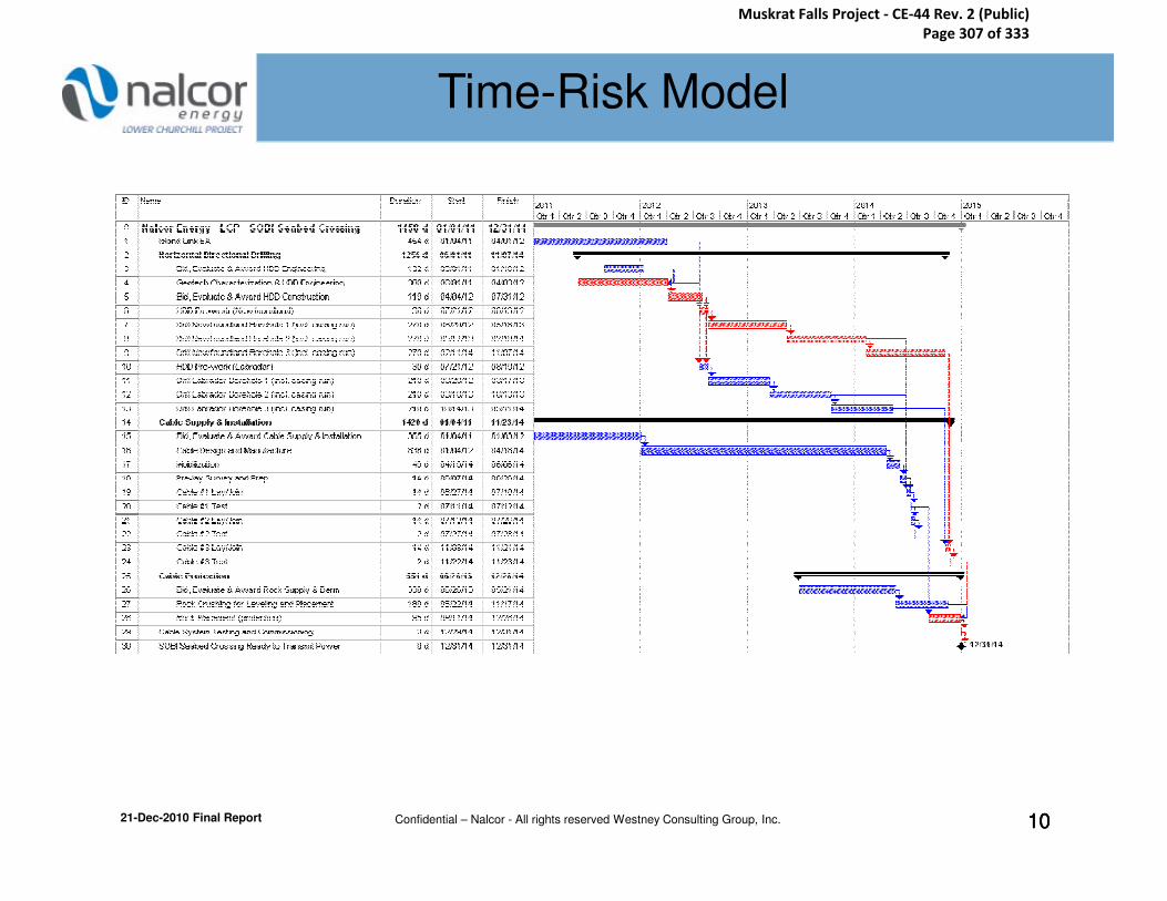
Lower Churchill
Project Risk Analysis
Lower Churchill Project
Risk AnalysisTime-Risk Model
21-Dec-2010 Final Report Confidential – Nalcor - All rights reserved Westney Consulting Group, Inc. 101010
Muskrat Falls Project - CE-44 Rev. 2 (Public) Page 307 of 333

Lower Churchill
Project Risk Analysis
Lower Churchill Project
Risk AnalysisTime-Risk Ranging
Ranging Sheet - SOBI Seabed Crossing
ID Task Description Duration Start Finish Best Worst
01 Island Link EA 454 d 4-Jan-11 1-Apr-12 150 456
02 Horizontal Directional Drilling 1256 d 1-Jun-11 7-Nov-14
03 Bid, Evaluate & Award HDD Engineering 132 d 1-Sep-11 10-Jan-12 -75 45
04 Geotech Characterization & HDD Engineering 308 d 1-Jun-11 3-Apr-12 -150 150
05 Bid, Evaluate & Award HDD Construction 119 d 4-Apr-12 31-Jul-12 0 90
06 HDD Pre-work (Newfoundland) 30 d 21-Jul-12 19-Aug-12 -10 60
Lower Churchill Project Time-Risk Assessment
Changes in DaysTime-Risk Model
21-Dec-2010 Final ReportConfidential – Nalcor - All rights reserved Westney Consulting Group, Inc. 11
07 Drill Newfoundland Borehole 1 (incl. casing run) 270 d 20-Aug-12 16-May-13 -90 240
08 Drill Newfoundland Borehole 2 (incl. casing run) 270 d 17-May-13 10-Feb-14 -90 120
09 Drill Newfoundland Borehole 3 (incl. casing run) 270 d 11-Feb-14 7-Nov-14 -90 120
10 HDD Pre-work (Labrador) 30 d 21-Jul-12 19-Aug-12 -10 60
11 Drill Labrador Borehole 1 (incl. casing run) 210 d 20-Aug-12 17-Mar-13 -60 160
12 Drill Labrador Borehole 2 (incl. casing run) 210 d 18-Mar-13 13-Oct-13 -60 80
13 Drill Labrador Borehole 3 (incl. casing run) 210 d 14-Oct-13 11-May-14 -60 80
14 Cable Supply & Installation 1420 d 4-Jan-11 23-Nov-14
15 Bid, Evaluate & Award Cable Supply & Installation 365 d 4-Jan-11 3-Jan-12 -30 90
16 Cable Design and Manufacture 836 d 4-Jan-12 18-Apr-14 -120 120
17 Mobilization 49 d 19-Apr-14 6-Jun-14
18 Pre-lay Survey and Prep. 14 d 7-Jun-14 26-Jun-14 -8 8
19 Cable #1 Lay/Join 14 d 27-Jun-14 10-Jul-14 -4 14
20 Cable #1 Test 2 d 11-Jul-14 12-Jul-14
Muskrat Falls Project - CE-44 Rev. 2 (Public) Page 308 of 333
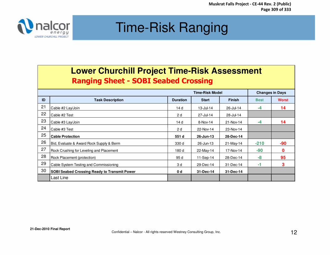
Lower Churchill
Project Risk Analysis
Lower Churchill Project
Risk AnalysisTime-Risk Ranging
Ranging Sheet - SOBI Seabed Crossing
ID Task Description Duration Start Finish Best Worst
21 Cable #2 Lay/Join 14 d 13-Jul-14 26-Jul-14 -4 14
22 Cable #2 Test 2 d 27-Jul-14 28-Jul-14
23 Cable #3 Lay/Join 14 d 8-Nov-14 21-Nov-14 -4 14
24 Cable #3 Test 2 d 22-Nov-14 23-Nov-14
Lower Churchill Project Time-Risk Assessment
Changes in DaysTime-Risk Model
21-Dec-2010 Final ReportConfidential – Nalcor - All rights reserved Westney Consulting Group, Inc. 12
24 Cable #3 Test 2 d 22-Nov-14 23-Nov-14
25 Cable Protection 551 d 26-Jun-13 28-Dec-14
26 Bid, Evaluate & Award Rock Supply & Berm 330 d 26-Jun-13 21-May-14 -210 -90
27 Rock Crushing for Leveling and Placement 180 d 22-May-14 17-Nov-14 -90 0
28 Rock Placement (protection) 95 d 11-Sep-14 28-Dec-14 -8 95
29 Cable System Testing and Commissioning 3 d 29-Dec-14 31-Dec-14 -1 3
30 SOBI Seabed Crossing Ready to Transmit Power 0 d 31-Dec-14 31-Dec-14
Last Line
Muskrat Falls Project - CE-44 Rev. 2 (Public) Page 309 of 333

Lower Churchill
Project Risk Analysis
Lower Churchill Project
Risk AnalysisTime-Risk Assessment Results
LCP - SOBI Seabed Crossing
Ready to Transmit Power - Time-Risk Analysis
70%
80%
90%
100%
Cu
mu
lati
ve P
rob
ab
ilit
y
Risk Resolution®Risk Resolution®
P75 = 20 Jul 16
Time-Risk Results
Confidential – Nalcor - All rights reserved Westney Consulting Group, Inc. 13
0%
10%
20%
30%
40%
50%
60%
Jan-15 May-15 Sep-15 Jan-16 May-16 Sep-16 Jan-17 May-17 Sep-17 Jan-18
Ready to Transmit Power
Cu
mu
lati
ve P
rob
ab
ilit
y
PRIMSTM
P25 = 11 Oct 15
P50 = 22 May 16Ready to Transmit Power
P90 19 Sep 16
P75 20 Jul 16
P25 11 Oct 15
P10 01 Aug 15
Predictive
Range
Time-Risk Results
Ice
Cover
Ice
Cover
Ice
Cover
Muskrat Falls Project - CE-44 Rev. 2 (Public) Page 310 of 333
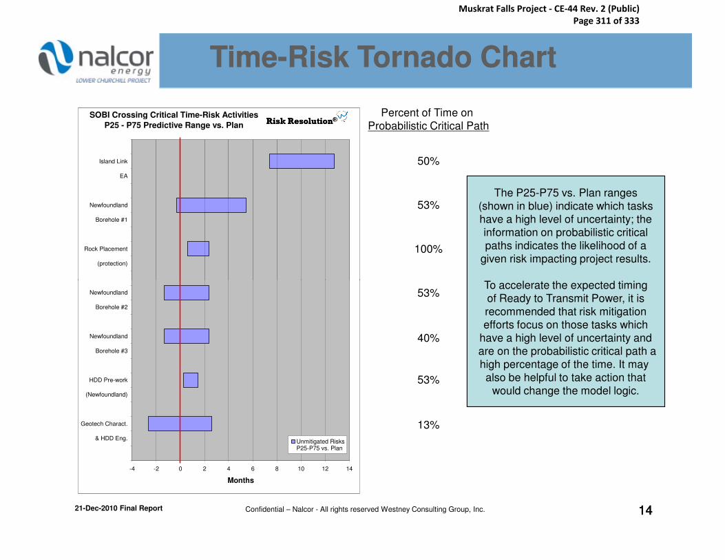
Lower Churchill
Project Risk Analysis
Lower Churchill Project
Risk AnalysisTimeTime--Risk Tornado ChartRisk Tornado Chart
The P25-P75 vs. Plan ranges
(shown in blue) indicate which tasks
have a high level of uncertainty; the
information on probabilistic critical
paths indicates the likelihood of a
given risk impacting project results.
To accelerate the expected timing
SOBI Crossing Critical Time-Risk Activities
P25 - P75 Predictive Range vs. Plan
(protection)
Rock Placement
Borehole #1
Newfoundland
EA
Island Link
Risk Resolution®Risk Resolution®Percent of Time on
Probabilistic Critical Path
50%
53%
100%
21-Dec-2010 Final Report Confidential – Nalcor - All rights reserved Westney Consulting Group, Inc. 141414
To accelerate the expected timing
of Ready to Transmit Power, it is
recommended that risk mitigation
efforts focus on those tasks which
have a high level of uncertainty and
are on the probabilistic critical path a
high percentage of the time. It may
also be helpful to take action that
would change the model logic.
-4 -2 0 2 4 6 8 10 12 14
& HDD Eng.
Geotech Charact.
(Newfoundland)
HDD Pre-work
Borehole #3
Newfoundland
Borehole #2
Newfoundland
Months
Unmitigated RisksP25-P75 vs. Plan
53%
40%
53%
13%
Muskrat Falls Project - CE-44 Rev. 2 (Public) Page 311 of 333

Lower Churchill
Project Risk Analysis
Lower Churchill Project
Risk AnalysisTime-Risk Milestones
Milestone Description P25 P50 P75
All HDD Complete 28 Jun. 2015 26 Oct. 2015 08 Mar. 2016
Cable #2 Installed/Tested 18 Dec. 2014 09 Jul. 2015 29 Jul. 2015
21-Dec-2010 Final Report Confidential – Nalcor - All rights reserved Westney Consulting Group, Inc. 151515
Rock Placement Complete 05 Oct. 2015 10 May 2016 15 Jul. 2016
Muskrat Falls Project - CE-44 Rev. 2 (Public) Page 312 of 333

Lower Churchill
Project Risk Analysis
Lower Churchill Project
Risk Analysis
The Tactical-Risk Assessment considers the impact of definition and performancerisks on the project cost estimate. Nalcorprovided the estimate for the SOBI Crossing.Each cost estimate was broken down bymajor category. Adjustments were made tothe categories to reflect decisions madesince the estimate was published.
Assessment Results Basis of Assessment
The P50 of the Tactical-Risk Assessment
equates to the cost estimate plus the
recommended contingency. The Tactical-
Risk Assessment yields the following results
for the SOBI Crossing:
Millions of C$
Tactical-Risk Assessment
21-Dec-2010 Final Report Confidential – Nalcor - All rights reserved Westney Consulting Group, Inc. 1616
Westney consultants met with the Nalcor project team to discuss the Best andWorst Case ranges around the estimate foreach cost category using input from RiskDiscovery as key framing input. The finalranging was performed by Nalcor, but it wasvetted and questioned by the WestneyParticipants. Westney selected theProbability distributions to use with theranged data and ran the Monte Carlosimulation.
Millions of C$
Tactical-Risk P50: $350SOBI Crossing Estimate(1): - $310
Recommended Contingency: $40 (13%)
(1) September 14, 2010 Estimate
Muskrat Falls Project - CE-44 Rev. 2 (Public) Page 313 of 333
Lower Churchill
Project Risk Analysis
Lower Churchill Project
Risk AnalysisTactical-Risk Ranging
Lower Churchill Project - SOBI Seabed Crossing
Tactical Cost Ranging Sheet
Cost CategoryOriginal
Estimate
(C$ M)
Spent to
Date
(C$ M)
Special
Adjust-
ments
(C$ M)
Cost to be
Risked
(C$ M)
Best - What
% Less
Could It
Cost? (enter
as negative)
Worst - What
% More
Could It
Cost?
Best Cost
(C$ M)
Worst Cost
(C$ M)
Pre/Post Survey 0
Pre/Post Survey Total, C$ M 00 0
Horizontal Directional Drilling Site Works
Risk Range
Pre/Post Survey
Horizontal Directional Drilling Site Works
21-Dec-2010 Final Report Confidential – Nalcor - All rights reserved Westney Consulting Group, Inc. 1717
Horizontal Directional Drilling Site Works
HDD Site Works Total, C$ M 0
Cost of Compounds
Site Access / Foteau Excavation 2,250
Transition Compounds Total, C$ M 0 0
Cost for Rock Placement for Leveling
Mobilization and Demobilization
Seabed Leveling Total, C$ M 0
Cost for 3 Cables
Cable Supply Total, C$ M 0
Transition Compounds
Seabed Leveling
Cable Supply
Muskrat Falls Project - CE-44 Rev. 2 (Public) Page 314 of 333

Lower Churchill
Project Risk Analysis
Lower Churchill Project
Risk AnalysisTactical-Risk Ranging
Lower Churchill Project - SOBI Seabed Crossing
Tactical Cost Ranging Sheet
Cost CategoryOriginal
Estimate
(C$ M)
Spent to
Date
(C$ M)
Special
Adjust-
ments
(C$ M)
Cost to be
Risked
(C$ M)
Best - What
% Less
Could It
Cost? (enter
as negative)
Worst - What
% More
Could It
Cost?
Best Cost
(C$ M)
Worst Cost
(C$ M)
Mobilization and Demobilization for 2 Rigs
Contractor Submittals
Cost for 3 Newfoundland Boreholes
Cost for 3 Labrador Boreholes
Risk Range
Horizontal Directional Drilling
21-Dec-2010 Final Report Confidential – Nalcor - All rights reserved Westney Consulting Group, Inc. 1818
Vessel Cost
Horizontal Directional Drilling Total, C$ M 7
Installation Cost 4 1
Mobilization and Demobilization 8
Support Costs 1 1
Cable Installation Total, C$ M 2
Cost of Rock 6
Rock Installation
Mobilization and Demobilization 5 -
Loading Facility Upgrade 00 00 1
Rock Berms (three) Total, C$ M 1 -
Project Total Cost, C$ M 309,923 0 -4,084 305,839
Project Total Cost
Cable Installation
Rock Berms
Muskrat Falls Project - CE-44 Rev. 2 (Public) Page 315 of 333

Lower Churchill
Project Risk Analysis
Lower Churchill Project
Risk AnalysisTactical-Risk Assessment
LCP - SOBI Seabed CrossingTactical (Cost Estimate) Risk Assessment
60%
70%
80%
90%
100%
Cu
mu
lati
ve P
rob
ab
ilit
y
P90 = $ 415 Million
P75 = $ 384 Million
Cdn$ Millions
Tactical Risk
Risk Resolution®Risk Resolution®
21-Dec-2010 Final Report Confidential – Nalcor - All rights reserved Westney Consulting Group, Inc. 1919
0%
10%
20%
30%
40%
50%
60%
200 230 260 290 320 350 380 410 440 470 500
Millions of Cdn$
Cu
mu
lati
ve P
rob
ab
ilit
y
P50 = $ 350 Million
P25 = $ 317 Million
P10 = $ 288 Million
Cdn$ Millions
P90 415
P75 384
P25 317
P10 288
Predictive
Range
PRIMSTM
14 Sep 2010 Estimate:
$ 310 Million = P21
Muskrat Falls Project - CE-44 Rev. 2 (Public) Page 316 of 333

Lower Churchill
Project Risk Analysis
Lower Churchill Project
Risk Analysis
The Strategic-Risk Assessment does not
include the impact of tactical risks (i.e.,
estimate contingency) on the costs of the
Lower Churchill Project. This assessment
dealt solely with CAPEX issues.
The strategic risks for the SOBI Crossing
Assessment Results Basis of Assessment
The Strategic Risk Exposure is the range of
the costs that might be incurred that
currently would not be incorporated into the
estimate. A decision will be required as to
whether these risks become costs in the
estimate or remain as Risk Exposure above
the estimate.
Strategic-Risk Assessment
21-Dec-2010 Final Report Confidential – Nalcor - All rights reserved Westney Consulting Group, Inc. 2020
The strategic risks for the SOBI Crossing
were identified and framed on a preliminary
basis by the Nalcor team. Westney
consultants met with the Nalcor project team
to discuss possible outcomes for the
unmitigated cases. The final ranging was
performed by the Nalcor team, but it was
vetted and questioned by the Westney
participants. Mitigation strategies were
endorsed by the project team. The Monte
Carlo simulations were run by Westney.
the estimate.
Predictive Range
P25 (mil) P75 (mil)
Unmitigated Risk Exposure $64 $136
Mitigated Risk Exposure* $-2 $30
*Includes costs of mitigation.All currency is in C$.
Muskrat Falls Project - CE-44 Rev. 2 (Public) Page 317 of 333

Lower Churchill
Project Risk Analysis
Lower Churchill Project
Risk Analysis
The following probability weightings were used in conjunction with probability distributions to analyze the Strategic Risks and the Risk Mitigations.
Strategic-Risk Modeling
Classification Probability
Remote 0% - 2%
21-Dec-2010 Final Report Confidential – Nalcor - All rights reserved Westney Consulting Group, Inc. 21
Remote 0% - 2%
Very Low 3% - 10%
Low 11% - 35%
Medium 36% - 64%
High 65% - 89%
Very High 90% - 97%
Almost Certain 98% -100%
Muskrat Falls Project - CE-44 Rev. 2 (Public) Page 318 of 333
Lower Churchill
Project Risk Analysis
Lower Churchill Project
Risk Analysis
Geotechnical evaluation of the HDD sites has not
been completed
1– Challenging HDD site and drilling conditions
– Possible Mitigation - significant geotechnical investigation/evaluation
• Pilot hole(s) and other bore samples
• Geotechnical and drilling studies
• Environmental impact analysis
Probability / Impact ($MM)UnmitigatedMitigated*
*including cost of mitigation
Medium / $60Low / $60
Definition Risks
Strategic Risks Considered in Analysis
Key Risks / Possible MitigationsKey Risks / Possible Mitigations
10-Dec-2010 Draft-For DiscussionConfidential – Nalcor - All rights reserved Westney Consulting Group, Inc. 22
2 – Delayed decisions leading to schedule slippage
and cost increases
– Incorrect cable length order/ change during manufacturing
– Possible Mitigation – Early selection of sites with proper geotechnical /environmental evaluation
Final length and
specification of subsea
cable not established
3
– Late location of Transition Compounds
– Changed transmission requirements
– Re-routing on seabed
– Possible Mitigation – Early selection of sites, detailed
survey of the seabed route, and Vessel Program
Final locations for the Transition Compounds not established
Very Low / $10Very Low / $1
Very Low / $20Remote / $1
• Pilot bore and Geotechnical program
Muskrat Falls Project - CE-44 Rev. 2 (Public) Page 319 of 333

Lower Churchill
Project Risk Analysis
Lower Churchill Project
Risk Analysis
– Late changes in the thickness of rock cover
– Late changes in the width of the rock berm
– Possible Mitigation – Long term current studies
Engineering data dependences have not
5 – 2011 studies, investigations, and surveys may produce
inappropriate detail or incorrect information
Definition Risks (Continued)
Very Low / $30Remote / $1
Very Low / $30
Thickness and volume of subsea cable rock cover
has not been finalized
4
Bold Comments
are Possible
Mitigations
Key Risks / Possible MitigationsKey Risks / Possible Mitigations
Strategic Risks Considered in Analysis
Probability / Impact ($MM)UnmitigatedMitigated*
*including cost of mitigation
10-Dec-2010 Draft-For DiscussionConfidential – Nalcor - All rights reserved Westney Consulting Group, Inc. 23
dependences have not
been established
inappropriate detail or incorrect information
– Possible Mitigation – Detailed planning of engineering data requirements and dependencies to verify completeness of planned 2011 investigations, surveys & studies
EA Significantly delays Cable order and site work
6 – Delays placement of cable order – missed manufacturing
slot – missed vessel availability
– Delays HDD site work - delays installation and Mechanical
Completion
– Possible Mitigation– increase LCP team resources to allow for proactive management and support of the EA process. Socialize the need for possible funding to procure long-lead items and vessel commitments
Enterprise Risks
Very Low / $30Remote / $5
High / $30High / $30
Muskrat Falls Project - CE-44 Rev. 2 (Public) Page 320 of 333
Lower Churchill
Project Risk Analysis
Lower Churchill Project
Risk Analysis
Inability to attract and retain competent resources in Nalcor
7– High turnover of staff
– Rework, errors & omissions, lack of contractor oversight
– Possible Mitigation – Continue recruiting experienced people, early mobilization, implement HR practices for retention such as mentoring and succession planning, competitive with other local industry practices and rates
Enterprise Risks (Continued)
Medium / $20Very Low / $5
Key Risks / Possible MitigationsKey Risks / Possible Mitigations
Strategic Risks Considered in Analysis
Bold Comments
are Possible
Mitigations
Probability / Impact ($MM)UnmitigatedMitigated*
*including cost of mitigation
10-Dec-2010 Draft-For DiscussionConfidential – Nalcor - All rights reserved Westney Consulting Group, Inc. 24
rates
Inability to bid, select, and award contracts in a timely manner
8– Project delays
– Inability to attract high-quality contractors
– Possible Mitigation – Alignment between Project Team and Supply Chain Management on coordination and requirements. Alignment with Nalcor management on funding requirements, added contracts resources
Medium / $30Very Low / $10
Poor governance impacts project and team performance
9 – High turnover of project personnel
– Project delays
– Increased rework
– Possible Mitigation – Clear delegations of authority for both commercial and technical decision-making along realistic timeframes for decisions
Very Low / $30Remote / $1
Muskrat Falls Project - CE-44 Rev. 2 (Public) Page 321 of 333
Lower Churchill
Project Risk Analysis
Lower Churchill Project
Risk Analysis
Interface
Transition Compound design and construction activities impact SOBI project performance
10 – Interface issues with EPCM delays project
– Possible Mitigation – Expedite engineering/operational requirements from Transmission Team. Locate Transition compounds where interference with the SOBI project can be minimised (i.e. separation of the landing site and transition compound, linked via land trenching), Interface & MOC processes
Low / $10Remote / $1
Key Risks / Possible MitigationsKey Risks / Possible Mitigations
Strategic Risks Considered in Analysis
Bold Comments
are Possible
Mitigations
Probability / Impact ($MM)UnmitigatedMitigated*
*including cost of mitigation
10-Dec-2010 Draft-For DiscussionConfidential – Nalcor - All rights reserved Westney Consulting Group, Inc. 25
Late requirements change from Transmission Project
11 – Significant project delays
– Reduced operability:
– Possible Mitigation – Early design requirements freeze on transmission power requirements, Interface & MOC processes
Low / $100Very Low/ $5
Muskrat Falls Project - CE-44 Rev. 2 (Public) Page 322 of 333

Lower Churchill
Project Risk Analysis
Lower Churchill Project
Risk Analysis
Unexpected conditions discovered after start of cable mfg. cause thermal management issues
12– Changes to the design of the rock protection
– Water circulation required within the HDD casing
– Added ancillary protection (ex. mattresses, grout bags, etc.)
– Possible Mitigation – Geotechnical program/ Pilot bore, Early HDD design, sediment analysis along the route survey, and early cable design for interface and drilling engineer mobilization
Engineering / Technical Risks
Very Low / $30Very Low / $5
Key Risks / Possible MitigationsKey Risks / Possible Mitigations
Strategic Risks Considered in Analysis
Bold Comments
are Possible
Mitigations
Probability / Impact ($MM)UnmitigatedMitigated*
*including cost of mitigation
10-Dec-2010 Draft-For DiscussionConfidential – Nalcor - All rights reserved Westney Consulting Group, Inc. 26
engineer mobilization
Very Low / $100Remote / $25
Iceberg scour damages cable during construction
14– Low Probability with limited opportunity to mitigate
beyond current design. Possible other mitigations include iceberg towing/deflection, flexible installation methods and scheduling, iceberg monitoring program
Remote / $30Remote / $30
Execution
– Significant project delay
– Possible start up with limited or no redundancy
– Possible Mitigation - Engage experienced engineering and construction contractors. Share risk with HDD contractor if possible, consider insurance products. Mobilize drilling engineer and contracting strategy
Deviations during HDD or design errors limit ability to pull/install cable without damage
13
Muskrat Falls Project - CE-44 Rev. 2 (Public) Page 323 of 333

Lower Churchill
Project Risk Analysis
Lower Churchill Project
Risk Analysis
Limited Contractor resources and poor
performance
15– Design errors, construction rework
– Project Delays / Added Cost
– Possible Mitigation – Early staffing and engagement, in-depth due diligence on all contractors, communications with local unions, key personnel provisions in contracts
16
Execution (Continued)
Low / $30Very Low / $15
Key Risks / Possible MitigationsKey Risks / Possible Mitigations
Strategic Risks Considered in Analysis
Bold Comments
are Possible
Mitigations
Probability / Impact ($MM)UnmitigatedMitigated*
*including cost of mitigation
10-Dec-2010 Draft-For DiscussionConfidential – Nalcor - All rights reserved Westney Consulting Group, Inc. 27
Unavailability of favorable cable manufacturing slots cause delay/added costs
16 – Project delays and/or added costs
– Use of lower tier manufacturer introduces additional risks
– Possible Mitigation – Early definition of cable length and specification, on-going monitoring of targeted companies’ backlogs, early bid and interface, availability of early funding to secure commitment
Unavailability of appropriate vessels cause delay/added cost
17– Project delays and/or added costs
– Use of lower tier manufacturer introduces additional risks
– Possible Mitigation – On-going monitoring of targeted vessel commitments, early bid to get flexibility, availability of early funding to secure commitments, turnkey contracting strategy of cable manufacture &
install
Very Low / $20Very Low / $5
Very Low / $30Remote / $1
Muskrat Falls Project - CE-44 Rev. 2 (Public) Page 324 of 333

Lower Churchill
Project Risk Analysis
Lower Churchill Project
Risk Analysis
Performance issues in the commodity supply chain cause project delays
18 – Construction delays and/or added cost
– Lowered productivity
– Possible Mitigation – detailed logistics planning by the project team and all contractors
Significant Weather
19 – Delayed offshore cable installation / rock placement
Execution Risks (Continued)
Key Risks / Possible MitigationsKey Risks / Possible Mitigations
Strategic Risks Considered in Analysis
Medium / $10Very Low / $3
Medium / $25
Bold Comments
are Possible
Mitigations
Probability / Impact ($MM)UnmitigatedMitigated*
*including cost of mitigation
10-Dec-2010 Draft-For DiscussionConfidential – Nalcor - All rights reserved Westney Consulting Group, Inc. 28
Significant Weather
Downtime (including currents, sea states, etc.)
– Delayed onshore construction
– Possible Mitigation – Start lay early/on time, detailed planning and timely execution to limit the work performed during adverse weather periods, shift liability for weather downtime to contractor
Other risks such as Foreign Exchange and Inflation were discussed. Because they will be
addressed by the Lower Churchill Project as a whole they were not included in this analysis.
Other Risks
Medium / $25Very Low / $5
Muskrat Falls Project - CE-44 Rev. 2 (Public) Page 325 of 333
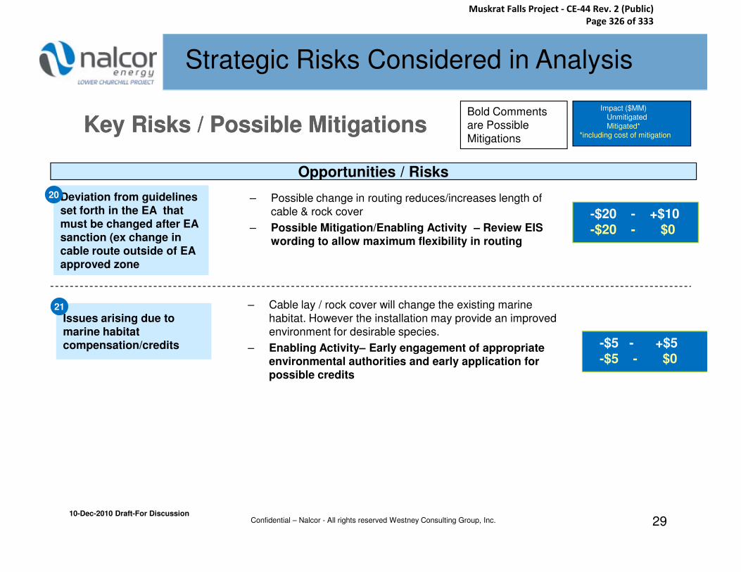
Lower Churchill
Project Risk Analysis
Lower Churchill Project
Risk Analysis
Deviation from guidelines
set forth in the EA that must be changed after EA
sanction (ex change in cable route outside of EA approved zone
20 – Possible change in routing reduces/increases length of
cable & rock cover
– Possible Mitigation/Enabling Activity – Review EIS wording to allow maximum flexibility in routing
Opportunities / Risks
Key Risks / Possible MitigationsKey Risks / Possible Mitigations
Strategic Risks Considered in Analysis
-$20 - +$10-$20 - $0
Bold Comments
are Possible
Mitigations
Impact ($MM)UnmitigatedMitigated*
*including cost of mitigation
10-Dec-2010 Draft-For DiscussionConfidential – Nalcor - All rights reserved Westney Consulting Group, Inc. 29
Issues arising due to marine habitat compensation/credits
21 – Cable lay / rock cover will change the existing marine
habitat. However the installation may provide an improved
environment for desirable species.
– Enabling Activity– Early engagement of appropriate environmental authorities and early application for possible credits
-$5 - +$5-$5 - $0
Muskrat Falls Project - CE-44 Rev. 2 (Public) Page 326 of 333

Lower Churchill
Project Risk Analysis
Lower Churchill Project
Risk AnalysisStrategic Risk Exposure
LCP - SOBI Seabed CrossingMitigated and Unmitigated Strategic Risk Assessments
60%
70%
80%
90%
100%
Cu
mu
lati
ve
Pro
ba
bil
ity
P75 = $ 136 MillionP75 = $ 30 Million
Risk Resolution®Risk Resolution®
P50 = $ 96 MillionP50 = $ 12 Million
Incremental Risk Exposure
above the estimate and
tactical risk exposure
21-Dec-2010 Final Report Confidential – Nalcor - All rights reserved Westney Consulting Group, Inc. 3030
0%
10%
20%
30%
40%
50%
-150 -120 -90 -60 -30 0 30 60 90 120 150 180 210 240 270
Risk Profile: Millions of Cdn$
Cu
mu
lati
ve
Pro
ba
bil
ity
P25 = $ 64 Million
PRIMSTM
P25 = $ -2 Million
Cdn$ Millions
P90 55
P75 30P25 -2
P10 -14
Predictive
Range
Mitigated Strategic Risk*
Cdn$ Millions
P90 183
P75 136P25 64
P10 38
Predictive
Range
Unmitigated Strategic Risk
*Includes cost of mitigation.
Muskrat Falls Project - CE-44 Rev. 2 (Public) Page 327 of 333
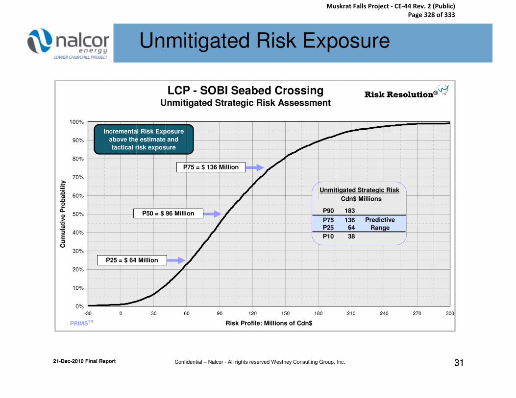
Lower Churchill
Project Risk Analysis
Lower Churchill Project
Risk AnalysisUnmitigated Risk Exposure
LCP - SOBI Seabed CrossingUnmitigated Strategic Risk Assessment
60%
70%
80%
90%
100%
Cu
mu
lati
ve P
rob
ab
ilit
y
P75 = $ 136 Million
Cdn$ Millions
Unmitigated Strategic Risk
Risk Resolution®Risk Resolution®
Incremental Risk Exposure
above the estimate and
tactical risk exposure
21-Dec-2010 Final Report Confidential – Nalcor - All rights reserved Westney Consulting Group, Inc. 3131
0%
10%
20%
30%
40%
50%
-30 0 30 60 90 120 150 180 210 240 270 300
Risk Profile: Millions of Cdn$
Cu
mu
lati
ve P
rob
ab
ilit
y
P25 = $ 64 Million
Cdn$ Millions
P90 183
P75 136
P25 64
P10 38
Predictive
Range
PRIMSTM
P50 = $ 96 Million
Muskrat Falls Project - CE-44 Rev. 2 (Public) Page 328 of 333

Lower Churchill
Project Risk Analysis
Lower Churchill Project
Risk AnalysisMitigated Risk Exposure
LCP - SOBI Seabed CrossingMitigated Strategic Risk Assessment
60%
70%
80%
90%
100%
Cu
mu
lati
ve P
rob
ab
ilit
y
P75 = $ 30 Million
Mitigated Strategic Risk
Risk Resolution®Risk Resolution®
Incremental Risk Exposure
above the estimate and
tactical risk exposure
21-Dec-2010 Final Report Confidential – Nalcor - All rights reserved Westney Consulting Group, Inc. 3232
0%
10%
20%
30%
40%
50%
60%
-60 -30 0 30 60 90 120 150 180 210 240 270
Risk Profile: Millions of Cdn$
Cu
mu
lati
ve P
rob
ab
ilit
y
P25 = $ -2 Million
Cdn$ Millions
P90 55
P75 30P25 -2
P10 -14
Predictive
Range
Mitigated Strategic Risk
PRIMSTM
P50 = $ 12 Million
Muskrat Falls Project - CE-44 Rev. 2 (Public) Page 329 of 333

Lower Churchill
Project Risk Analysis
Lower Churchill Project
Risk AnalysisStrategic-Risk Tornado Chart
SOBI Seabed Crossing - Key Strategic Risks
Mean Values (probability weighted)
transmission project
R11: Late changes from
not timely
R8: Contract awards
creates delays
R6: EA timing
unknowns
R1: Geotechnical
Risk Resolution®Risk Resolution®
21-Dec-2010 Final Report Confidential – Nalcor - All rights reserved Westney Consulting Group, Inc. 333333
0 2 4 6 8 10 12 14 16 18 20
to install cable
R13: Limited ability
commodity supply chain
R18: Issues with
resources are limited
R15: Available contractor
not attracted / retained
R7: Competent resources
weather downtime
R19: Significant
Millions of Cdn$
Unmitigated Mean Value
Mitigated Mean Value(including cost of mitigation)
Muskrat Falls Project - CE-44 Rev. 2 (Public) Page 330 of 333

Lower Churchill
Project Risk Analysis
Lower Churchill Project
Risk Analysis
Supplemental Information
21-Dec-2010 Final Report Confidential – Nalcor - All rights reserved Westney Consulting Group, Inc. 343434
Supplemental Information
Muskrat Falls Project - CE-44 Rev. 2 (Public) Page 331 of 333

Lower Churchill
Project Risk Analysis
Lower Churchill Project
Risk AnalysisPredictive Range
Predictive Range: The term predictive range is used
throughout this report when describing the results
of Monte Carlo simulations for all types of risk
assessments. Specifically, the predictive range
refers to the P25 to P75 band of results for a
given assessment. Because the predictive range
21-Dec-2010 Final Report Confidential – Nalcor - All rights reserved Westney Consulting Group, Inc. 353535
given assessment. Because the predictive range
is comprised of the middle 50% of the results,
it is usually thought to be the most relevant
indicator of future outcomes when assessing
a modeled situation. T
Muskrat Falls Project - CE-44 Rev. 2 (Public) Page 332 of 333

Lower Churchill
Project Risk Analysis
Lower Churchill Project
Risk AnalysisWeather Windows - Time-Risk Activities
The following weather windows are used in the Time-Risk analysis:
For Task 18: Pre-lay Survey and Prep.
Task 19: Cable #1 Lay/Join
Task 21: Cable #2 Lay/Join
Task 23: Cable #3 Lay/Join
Task 28: Rock Placement (protection)
21-Dec-2010 Final Report Confidential – Nalcor - All rights reserved Westney Consulting Group, Inc. 363636
Task 28: Rock Placement (protection)
January 1 – April 15: Ice Cover - No offshore activity
April 16 – June 15: 25% productivity
June 16 – November 30: 100% productivity
December 1 – December 31: 50% productivity
T
Muskrat Falls Project - CE-44 Rev. 2 (Public) Page 333 of 333


![SOBI Paper[1]](https://static.cupdf.com/doc/110x72/577d28ee1a28ab4e1ea59490/sobi-paper1.jpg)