Lecture 5Cameras, Projection, and Image
Formation
© UW CSE vision faculty

Lesson from today’s presidential inauguration
Vanishing point
(from New York Times)
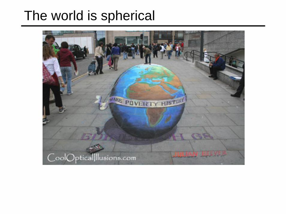
The world is spherical

Wait…the world is flat
The brain constructs a 3D interpretation consistent with the 2D projection of the scene on your retina
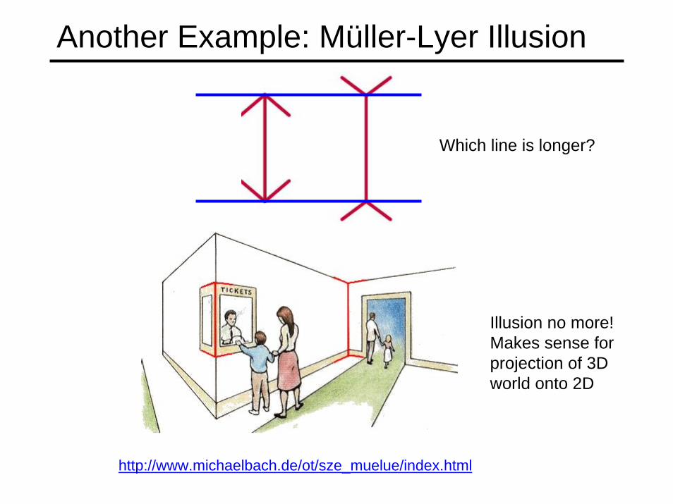
Another Example: Müller-Lyer Illusion
http://www.michaelbach.de/ot/sze_muelue/index.html
Which line is longer?
Illusion no more! Makes sense for projection of 3D world onto 2D

Image formation
Let’s design a camera• Idea 1: put a piece of film in front of an object• Do we get a reasonable image?
object filmFilm (or sensor array)
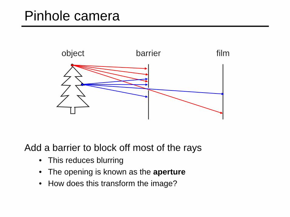
Pinhole camera
Add a barrier to block off most of the rays• This reduces blurring• The opening is known as the aperture• How does this transform the image?
object filmbarrier
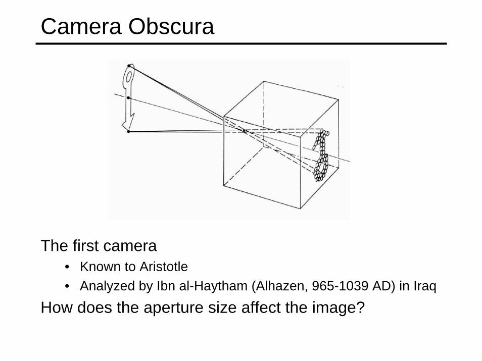
Camera Obscura
The first camera• Known to Aristotle• Analyzed by Ibn al-Haytham (Alhazen, 965-1039 AD) in Iraq
How does the aperture size affect the image?

Shrinking the aperture
Why not make the aperture as small as possible?• Less light gets through• Diffraction effects...

Shrinking the aperture

Adding a lens
A lens focuses light onto the film• There is a specific distance at which objects are “in focus”
– other points project to a “circle of confusion” in the image• Changing the shape of the lens changes this distance
object filmlens
“circle of confusion”

Lenses
A lens focuses parallel rays onto a single focal point• focal point at a distance f beyond the plane of the lens
– f is a function of the shape and index of refraction of the lens
• Aperture of diameter D restricts the range of rays– aperture may be on either side of the lens
• Lenses are typically spherical (easier to produce)
focal point
F
optical center(Center Of Projection)

Thin lenses
Thin lens equation (derived using similar triangles):
• Any object point satisfying this equation is in focus (assuming d0 > f)
– What happens when do < f? (e.g, f = 2 and do = 1)
Thin lens applet: http://www.phy.ntnu.edu.tw/java/Lens/lens_e.html

When do < f, di becomes negative
We get a virtual image that an observer looking through the lens can see (as with a magnifying glass)Magnification by the lens is defined as:
Magnification
oo
i
dff
ddM
−=−=
(M positive for upright (virtual) images, negative for real images)
|M| > 1 indicates magnification
From wikipedia
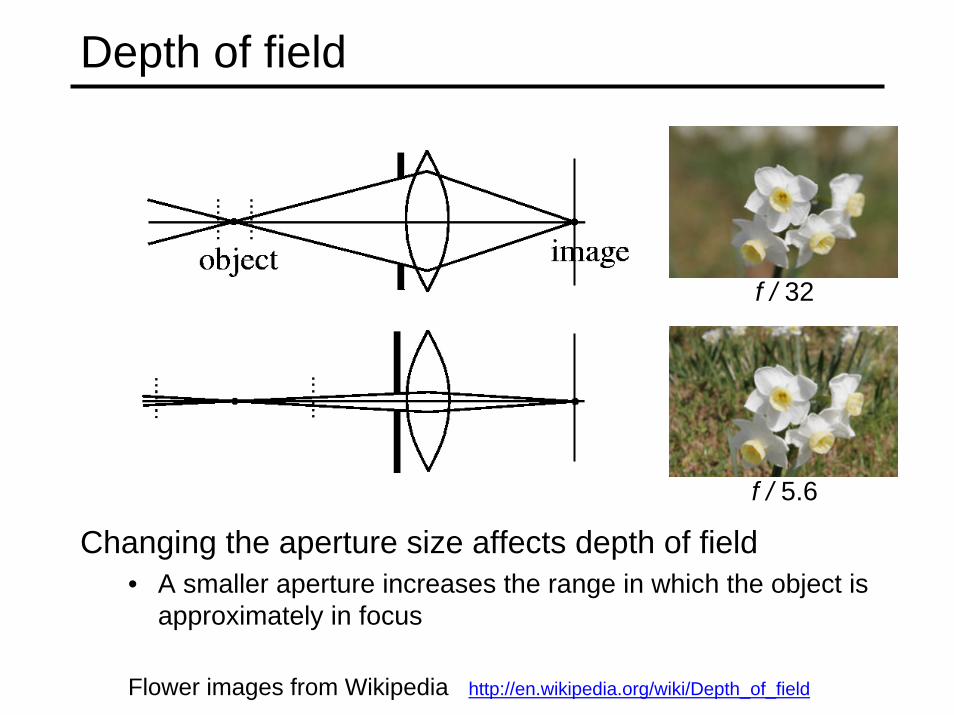
Depth of field
Changing the aperture size affects depth of field• A smaller aperture increases the range in which the object is
approximately in focus
f / 32
f / 5.6
Flower images from Wikipedia http://en.wikipedia.org/wiki/Depth_of_field

The eye
The human eye is a camera• Iris - colored disc with radial muscles and hole in the center• Pupil - the hole (aperture) in iris whose size is controlled by iris muscles• What’s the “film”?
– photoreceptor cells (rods and cones) in the retina
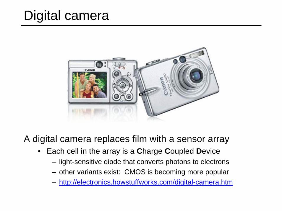
Digital camera
A digital camera replaces film with a sensor array• Each cell in the array is a Charge Coupled Device
– light-sensitive diode that converts photons to electrons– other variants exist: CMOS is becoming more popular– http://electronics.howstuffworks.com/digital-camera.htm

Issues with digital cameras
Noise– big difference between consumer vs. SLR-
style cameras– low light is where you most notice noise
Compression– creates artifacts except in uncompressed
formats (tiff, raw) Color
– color fringing artifactsBlooming
– charge overflowing into neighboring pixelsIn-camera processing
– oversharpening can produce halosStabilization
– compensate for camera shake (mechanical vs. electronic)
Interlaced vs. progressive scan video– even/odd rows from different exposures vs
entire picture
Interlaced Progressive

Modeling projection
The coordinate system• We will use the pin-hole camera as an approximation• Put the optical center (Center Of Projection) at the origin• Put the image plane (Projection Plane) in front of the COP – Why?
– avoids inverted image and geometrically equivalent• The camera looks down the negative z axis
– we need this if we want right-handed-coordinates
Pinhole camera Model

Modeling projection
Projection equations• Compute intersection with image plane PP of ray from (x,y,z) to COP• Derived using similar triangles (on board)
• Get projection coordinates on image by throwing out last coordinate:
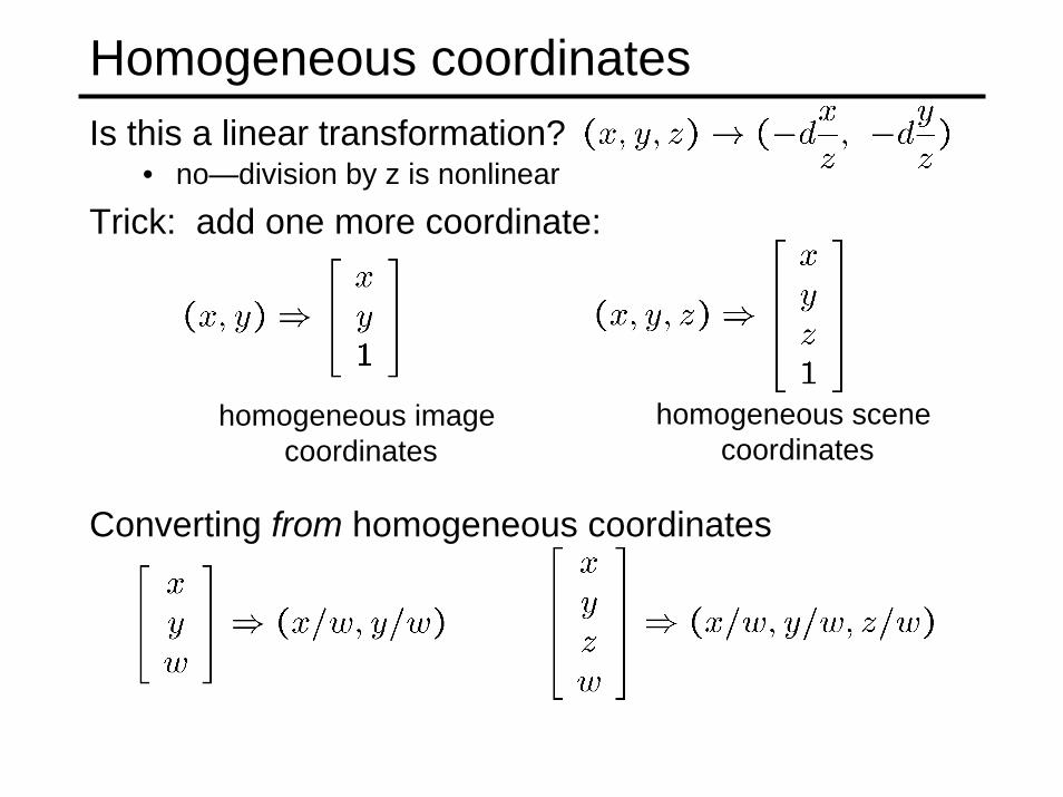
Homogeneous coordinatesIs this a linear transformation?
Trick: add one more coordinate:
homogeneous scene coordinates
homogeneous image coordinates
Converting from homogeneous coordinates
• no—division by z is nonlinear

(0,0,0)
z
Homogenous coordinates: Geometric intuitionHomogenous coords provide a way of extending N-d space to
(N+1)-d space• a point in the 2D image is treated as a ray in 3D projective space• Each point (x,y) on the image plane is represented by the ray
(sx,sy,s)– all points on the ray are equivalent: (x, y, 1) ≡ (sx, sy, s)
• Go back to 2D by dividing with last coordinate: (sx,sy,s)/s (x,y)
(sx,sy,s)
image plane
(x,y,1)y
x

Modeling ProjectionProjection is a matrix multiply using homogeneous coordinates:
divide by third coordinate and throw it out to get image coords
This is known as perspective projection• The matrix is the projection matrix• Can also formulate as a 4x4 (today’s handout does this)
divide by fourth coordinate and throw last two coordinates out

Perspective ProjectionHow does scaling the projection matrix change the transformation?
⎟⎠⎞
⎜⎝⎛ −−⇒
⎥⎥⎥
⎦
⎤
⎢⎢⎢
⎣
⎡
−=
⎥⎥⎥⎥
⎦
⎤
⎢⎢⎢⎢
⎣
⎡
⎥⎥⎥
⎦
⎤
⎢⎢⎢
⎣
⎡
−zyd
zxd
dczcycx
zyx
dcc
c,
/1
0/00000000
Scaling by c:
Same result if (x,y,z) scaled by c. This implies that:In the image, a larger object further away (scaled x,y,z) can
have the same size as a smaller object that is closer

Hence…

Vanishing points
image plane
line on ground plane
vanishing point v
Vanishing point• projection of a point at infinity
COP

Vanishing points
Properties• Any two parallel lines have the same vanishing point v• The ray from COP through v is parallel to the lines
image plane
COP
line on ground plane
vanishing point v
line on ground plane

Examples in Real Images
http://stevewebel.com/
http://phil2bin.com/
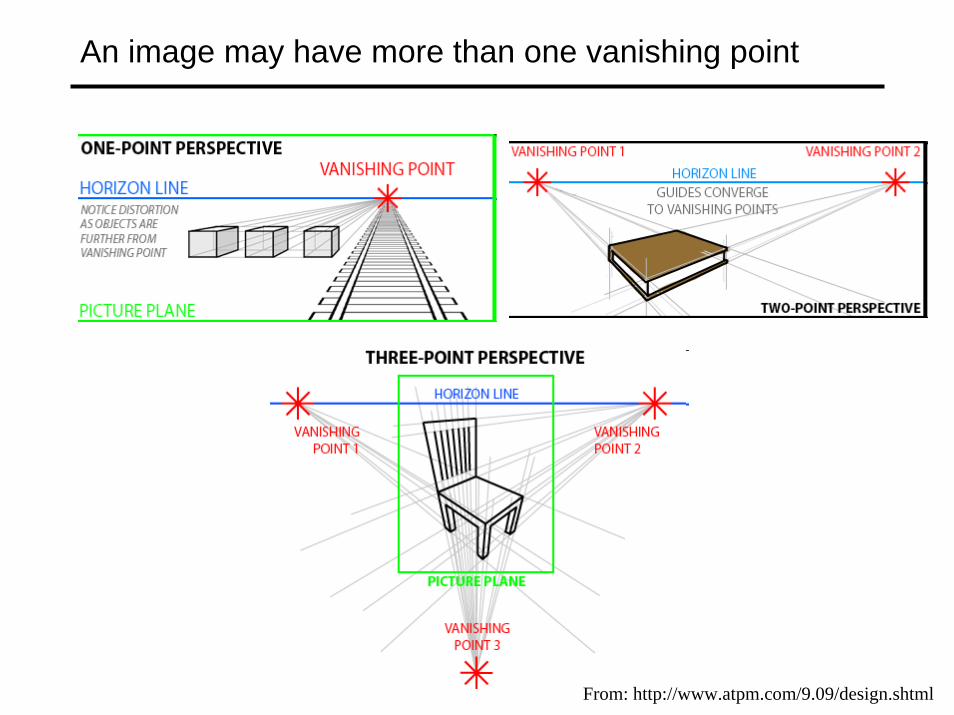
An image may have more than one vanishing point
From: http://www.atpm.com/9.09/design.shtml

Use in Art
Leonardo Da Vinci’s Last Supper

Simplified Projection Models
Weak Perspective and Orthographic
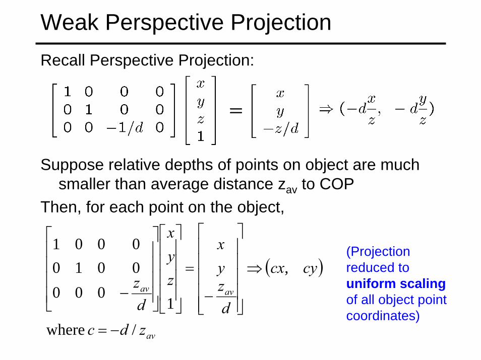
Weak Perspective ProjectionRecall Perspective Projection:
Suppose relative depths of points on object are much smaller than average distance zav to COP
Then, for each point on the object,
( )
av
avav
zdc
cycx
dzyx
zyx
dz
/ where
,
1000
00100001
−=
⇒
⎥⎥⎥⎥⎥
⎦
⎤
⎢⎢⎢⎢⎢
⎣
⎡
−
=
⎥⎥⎥⎥
⎦
⎤
⎢⎢⎢⎢
⎣
⎡
⎥⎥⎥⎥
⎦
⎤
⎢⎢⎢⎢
⎣
⎡
−
(Projection reduced to uniform scalingof all object point coordinates)
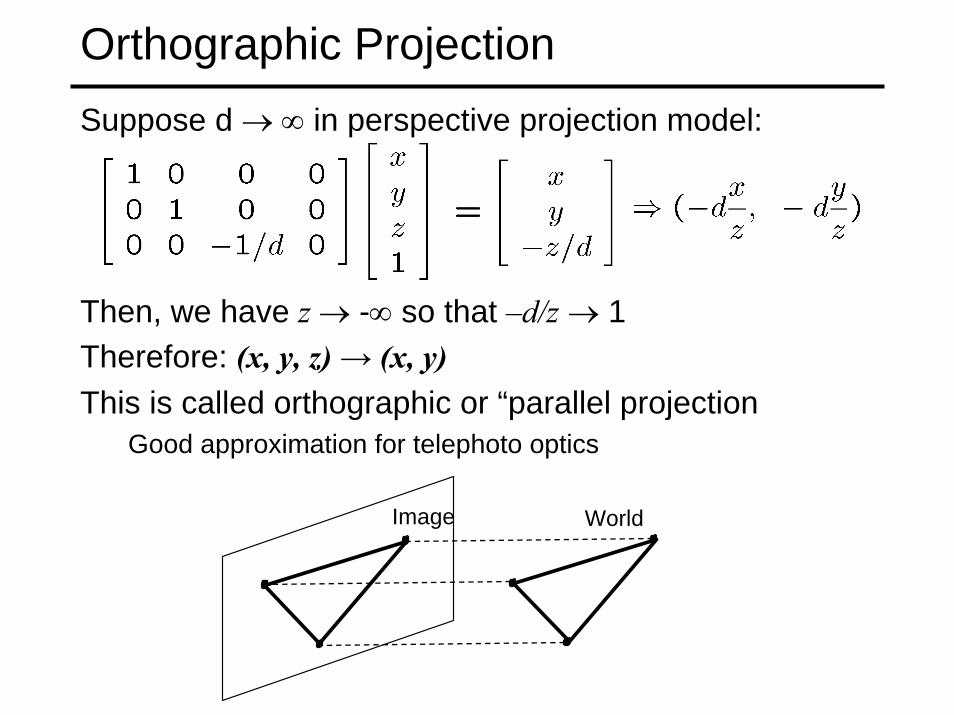
Orthographic ProjectionSuppose d → ∞ in perspective projection model:
Then, we have z → -∞ so that –d/z → 1Therefore: (x, y, z) → (x, y)This is called orthographic or “parallel projection
Good approximation for telephoto optics
Image World

Orthographic projection
What’s the projection matrix in homogenous coordinates?
Image World(x, y, z) → (x, y)
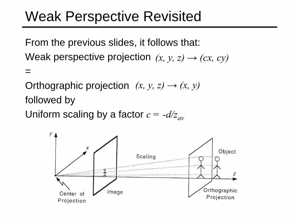
Weak Perspective Revisited
From the previous slides, it follows that:Weak perspective projection= Orthographic projection followed byUniform scaling by a factor c = -d/zav
(x, y, z) → (cx, cy)
(x, y, z) → (x, y)
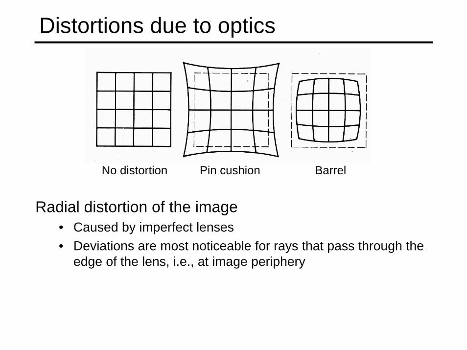
Distortions due to optics
Radial distortion of the image• Caused by imperfect lenses• Deviations are most noticeable for rays that pass through the
edge of the lens, i.e., at image periphery
No distortion Pin cushion Barrel

Distortion

Modeling Radial Distortion• Radial distortion is typically modeled as:
222
42
21
42
21
where
)1(
)1(
dd
d
d
yxr
rkrkyy
rkrkxx
+=
++=
++=
• (xd,yd) are coordinates of distorted points wrt image center• (x,y) are coordinates of the corrected points• Distortion is a radial displacement of image points
- increases with distance from center• k1 and k2 are parameters to be estimated• k1 usually accounts for 90% of distortion
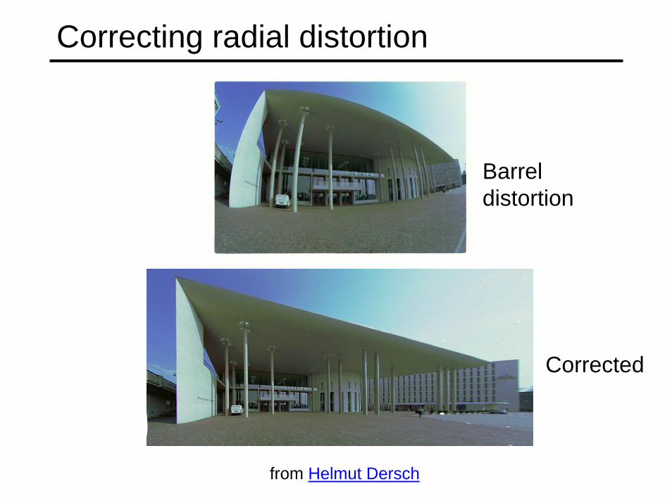
Correcting radial distortion
from Helmut Dersch
Barrel distortion
Corrected

Putting it all together: Camera parameters• Want to link coordinates of points in 3D external
space with their coordinates in the image• Perspective projection was defined in terms of
camera reference frame
• Need to find location and orientation of camera reference frame with respect to a known “world”reference frame (these are the extrinsic parameters)
Camera reference frame
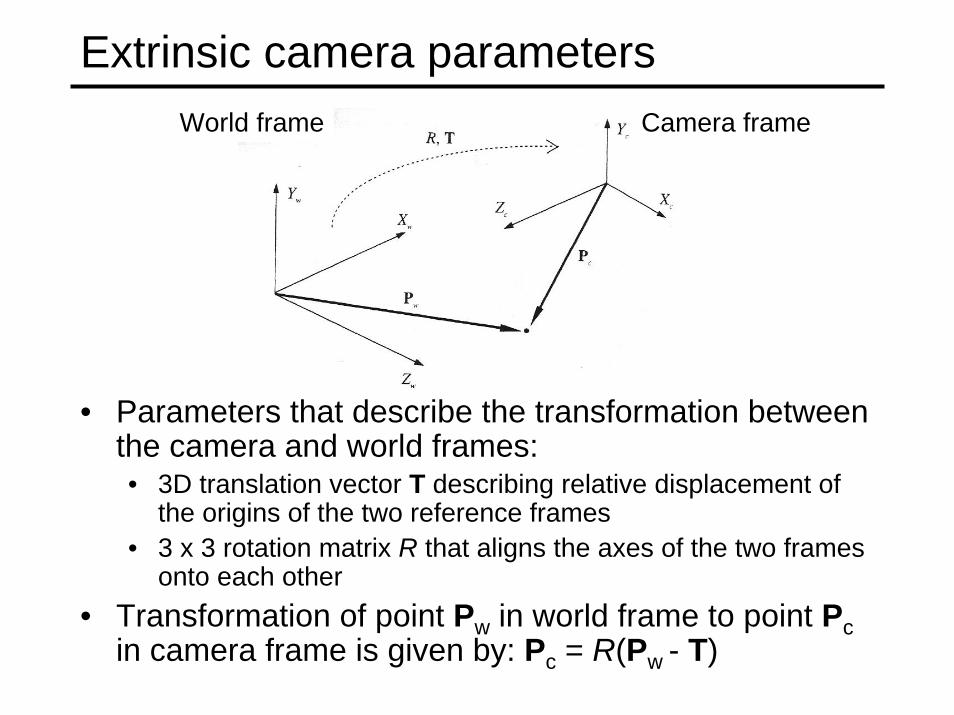
Extrinsic camera parameters
• Parameters that describe the transformation between the camera and world frames:• 3D translation vector T describing relative displacement of
the origins of the two reference frames• 3 x 3 rotation matrix R that aligns the axes of the two frames
onto each other• Transformation of point Pw in world frame to point Pc
in camera frame is given by: Pc = R(Pw - T)
Camera frameWorld frame

Intrinsic camera parameters• Parameters that characterize the optical, geometric
and digital properties of camera• Perspective projection parameter: focal length d in previous
slides• Distortion due to optics: radial distortion parameters k1, k2• Transformation from camera frame to pixel coordinates:
– Coordinates (xim,yim) of image point in pixel units related to coordinates (x,y) of same point in camera ref frame by:x = - (xim – ox)sxy = - (yim – oy)sywhere (ox,oy) is the image center and sx, sy denote size of pixel
(Note: - sign in equations above are due to opposite orientations of x/y axes in camera and image reference frames)
• Estimation of extrinsic and intrinsic parameters is called camera calibration• typically uses a 3D object of known geometry with image features
that can be located accurately
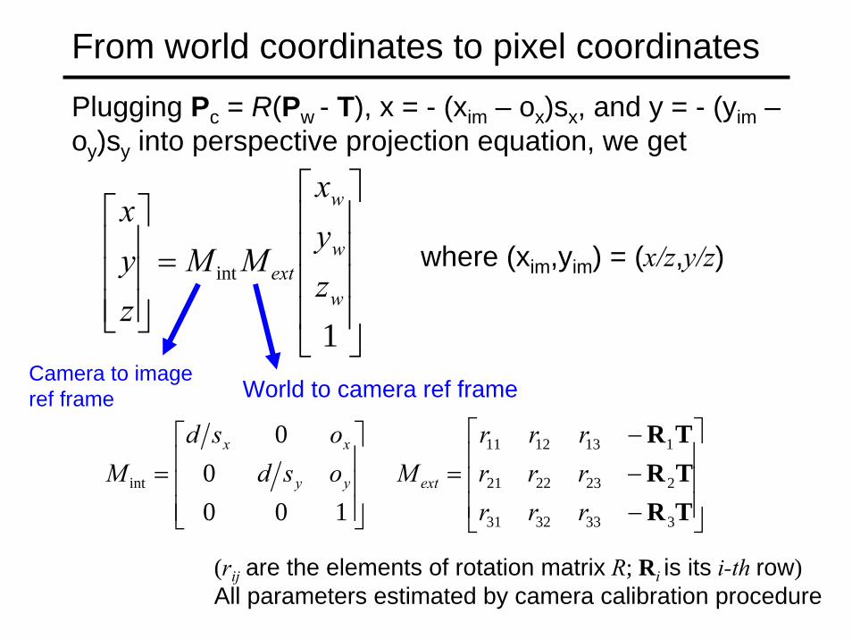
From world coordinates to pixel coordinatesPlugging Pc = R(Pw - T), x = - (xim – ox)sx, and y = - (yim –oy)sy into perspective projection equation, we get
1
int
⎥⎥⎥⎥
⎦
⎤
⎢⎢⎢⎢
⎣
⎡
=⎥⎥⎥
⎦
⎤
⎢⎢⎢
⎣
⎡
w
w
w
ext zyx
MMzyx
⎥⎥⎥
⎦
⎤
⎢⎢⎢
⎣
⎡
−−−
=⎥⎥⎥
⎦
⎤
⎢⎢⎢
⎣
⎡=
TRTRTR
3333231
2232221
1131211
int 100
00
rrrrrrrrr
Mosdosd
M extyy
xx
Camera to image ref frame
where (xim,yim) = (x/z,y/z)
(rij are the elements of rotation matrix R; Ri is its i-th row)All parameters estimated by camera calibration procedure
World to camera ref frame

Next time: Image Features & Interest Operators
• Things to do:• Work on Project 1: Use Sieg 327 if skeleton software not
working on your own computer
• Readings online How’s this for perspective?