C O M P A C T L I M I T S W I T C H
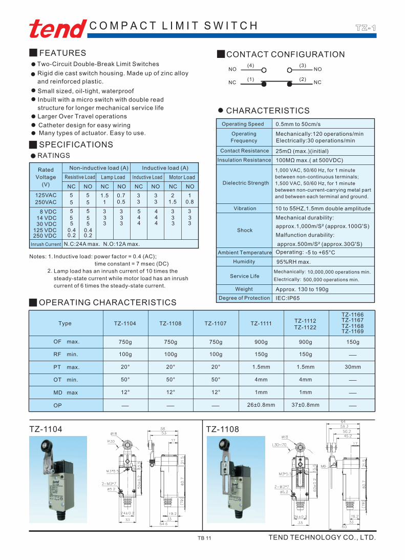
TZ-1104
MD max
OP
12°12°
OT min. 50°50°
Type
PT max. 20°20°
RF min. 100g100g
max.OF 750g750g
OPERATING CHARACTERISTICS
TZ-1108TZ-1104
NONCNONC NC NONONC
0.2 0.2250 VDCInrush Current N.C:24A max. N.O:12A max.
3 3453 38 VDC 5 5
34 33 435 530 VDC0.4 0.4125 VDC
5 514 VDC 334433
5 5250VAC 1.53 0.80.51 35 5125VAC 12331.5 0.7
SPECIFICATIONS
Motor LoadLamp Load Inductive LoadResistive LoadNon-inductive load (A) Inductive load (A)
RATINGS
Two-Circuit Double-Break Limit SwitchesFEATURES
500,000 operations min.Electrically:
TZ-1108
37±0.8mm26±0.8mm
1mm12° 1mm
4mm50° 4mm
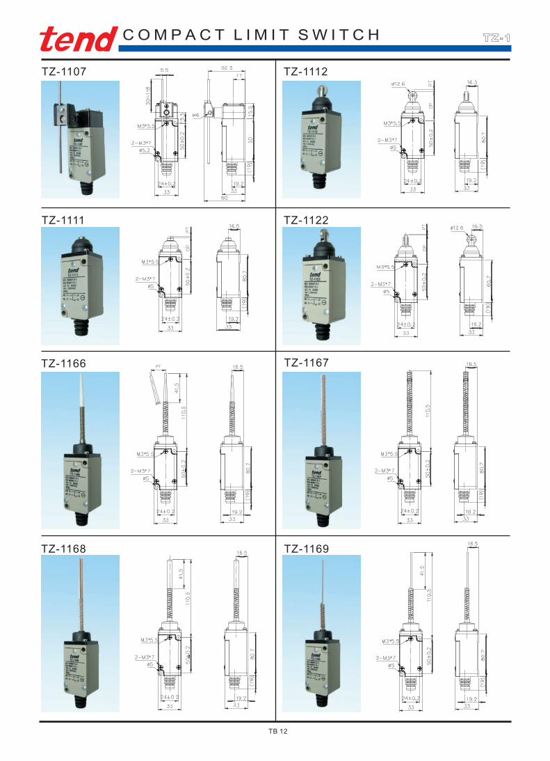
TZ-1168TZ-1122
1.5mm20° 1.5mm 30mm
150g100g 150g
900g750g 900g 150g
TZ-1169
TZ-1166TZ-1112TZ-1107 TZ-1111 TZ-1167
IEC:IP65Degree of ProtectionApprox. 130 to 190gWeight
CHARACTERISTICS
Mechanically: 10,000,000 operations min.Service Life
95%RH max.Humidity-5 to +65°COperating:Ambient Temperature
approx.500m/S² (approx.30G'S)
Mechanical durability:
Shockapprox.1,000m/S² (approx.100G'S)Malfunction durability:
Vibration 10 to 55HZ,1.5mm double amplitude
Insulation Resistance 100MΩ max.( at 500VDC)
Dielectric Strength
Mechanically:120 operations/min
25mΩ (max.)(initial)Contact Resistance
Electrically:30 operations/min
0.5mm to 50cm/sOperating Speed
CONTACT CONFIGURATION
NC
NO
(2)(1)
(4) (3)
NC
NO
TZ-1
TEND TECHNOLOGY CO., LTD.TB 11
Operating Frequency
1,000 VAC, 50/60 Hz, for 1 minute between non-continuous terminals; 1,500 VAC, 50/60 Hz, for 1 minute between non-current-carrying metal part and between each terminal and ground.
Rated Voltage
(V)
Inductive load: power factor = 0.4 (AC); time constant = 7 msec (DC)Lamp load has an inrush current of 10 times the steady-state current while motor load has an inrush current of 6 times the steady-state current.
Notes: 1.
2.
Rigid die cast switch housing. Made up of zinc alloy and reinforced plastic.
Inbuilt with a micro switch with double read structure for longer mechanical service life
Catheter design for easy wiringMany types of actuator. Easy to use.
Larger Over Travel operations
Small sized, oil-tight, waterproof
C O M P A C T L I M I T S W I T C H
TZ-1112
TZ-1169TZ-1168
TZ-1166 TZ-1167
TZ-1111 TZ-1122
TZ-1107
TZ-1
TB 12
InrushCurrent
(A)Motor LoadInductive load
Inductive load (A)
Lamp Load
Non-inductive load(A)RatedVoltage
(V)
10max.
10max.
10.5
21
33
1.51.51.50.050.03
_____
5
5
0.50.25
125 VAC
8 VDC
30 VDC125 VDC250 VDC
CHARACTERISTICS
SPECIFICATIONSRATINGS
NC
1.51.5
NC NO NC NO NO NC NONO NC
About 22 to 58g
Mechanically: 10,000,000 operations min.Electrically: 500,000 operations min.
Malfunction durability: 300m/Sec²(approx. 30G'S)
Max. 95%RH
N-10°C ~ +80°C ( ot freezing)
Malfunction durability:10~55Hz
0.01mm to 1m/sec(Plunger Type)
Mechanically: 240 operations/minElectrically: 20 operations/min
15mΩ max. (initial)
100MΩ min. (at 500VDC)
(*10~20HZ):1.5mm double amplitude
Operating Speed
Dielectric Strength
Vibration
Shock
Humidity
Service Life
Weight
TZ-2
Sealed: (IEC) IP67Degree of Protection
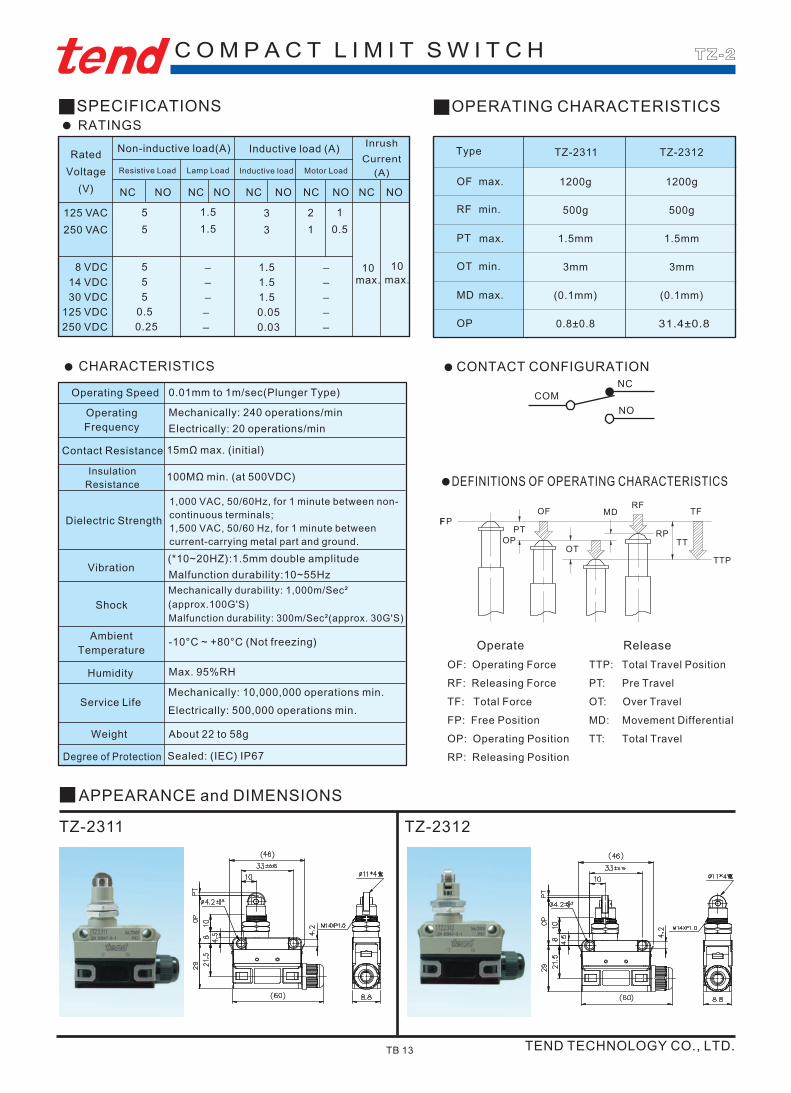
APPEARANCE and DIMENSIONS
TZ-2311 TZ-2312
OPERATING CHARACTERISTICS
1.5mm1.5mmPT
0.8±0.8 31.4±0.8OP
(0.1mm)(0.1mm)MD
3mmOT
max.
max.
min.
max.
min.
3mm
OF
RF 500g 500g
TZ-2312
1200g1200g
TZ-2311Type
_____
C O M P A C T L I M I T S W I T C H
DEFINITIONS OF OPERATING CHARACTERISTICS
NO
NCCOM
CONTACT CONFIGURATION
OperateOF: Operating ForceRF: Releasing ForceTF: Total ForceFP: Free PositionOP: Operating PositionRP: Releasing Position
TTP: Total Travel PositionPT: Pre TravelOT: Over TravelMD: Movement DifferentialTT: Total Travel
Release
TEND TECHNOLOGY CO., LTD.TB 13
Operating Frequency
Contact Resistance
Insulation Resistance
Ambient Temperature
1,000 VAC, 50/60Hz, for 1 minute between non-continuous terminals;1,500 VAC, 50/60 Hz, for 1 minute between current-carrying metal part and ground.
Mechanically durability: 1,000m/Sec² (approx.100G'S)
Resistive Load
5250 VAC
55
14 VDC
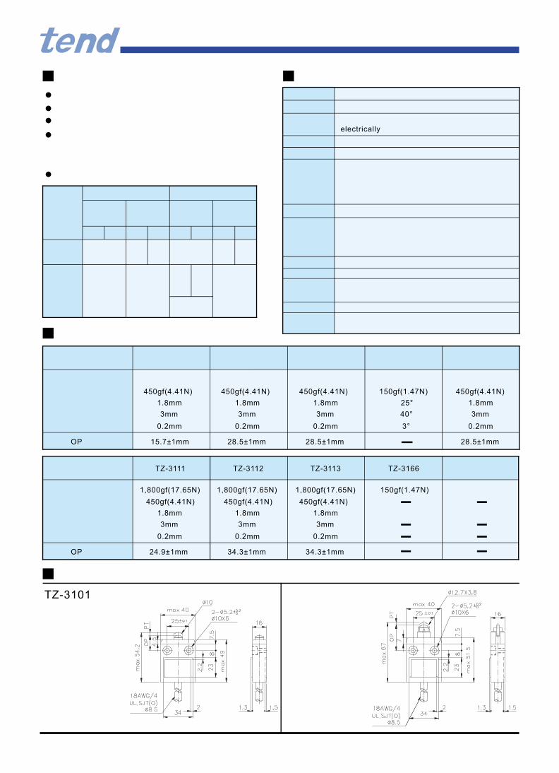
450gf(4.41N) 450gf(4.41N) 450gf(4.41N) 150gf(1.47N) 450gf(4.41N)
1.8mm1.8mm 1.8mm
OP
TZ-3101
24.9±1mm 34.3±1mm 34.3±1mm
0.2mm0.2mm 0.2mm
3mm3mm 3mm
OP
450gf(4.41N)450gf(4.41N) 450gf(4.41N)
1,800gf(17.65N)1,800gf(17.65N) 150gf(1.47N)1,800gf(17.65N)
TZ-3166TZ-3112TZ-3111 TZ-3113
15.7±1mm 28.5±1mm 28.5±1mm
0.2mm0.2mm 3°0.2mm
28.5±1mm
0.2mm
25°1.8mm1.8mm 1.8mm
3mm3mm 40°3mm
1.8mm
3mm
electrically
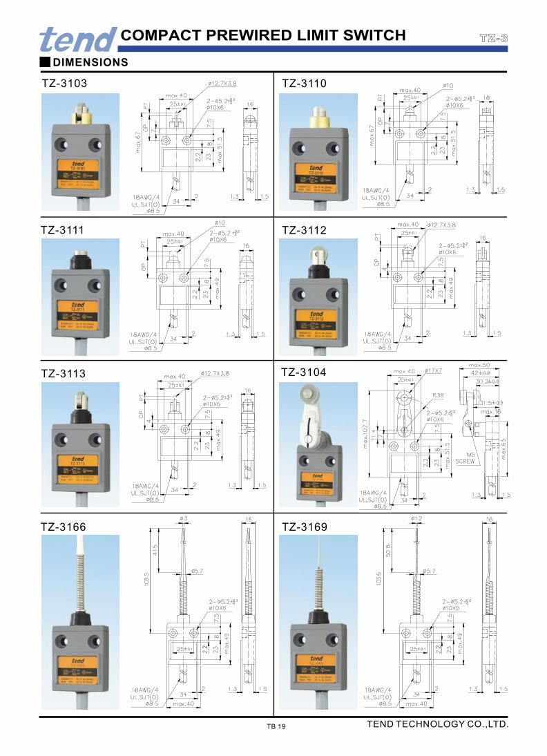
COMPACT PREWIRED LIMIT SWITCH
TZ-3112
TZ-3113
TZ-3110
TZ-3111
TZ-3103
TZ-3169
TZ-3104
TZ-3166
DIMENSIONS
TB 19
TZ-3
TEND TECHNOLOGY CO.,LTD.
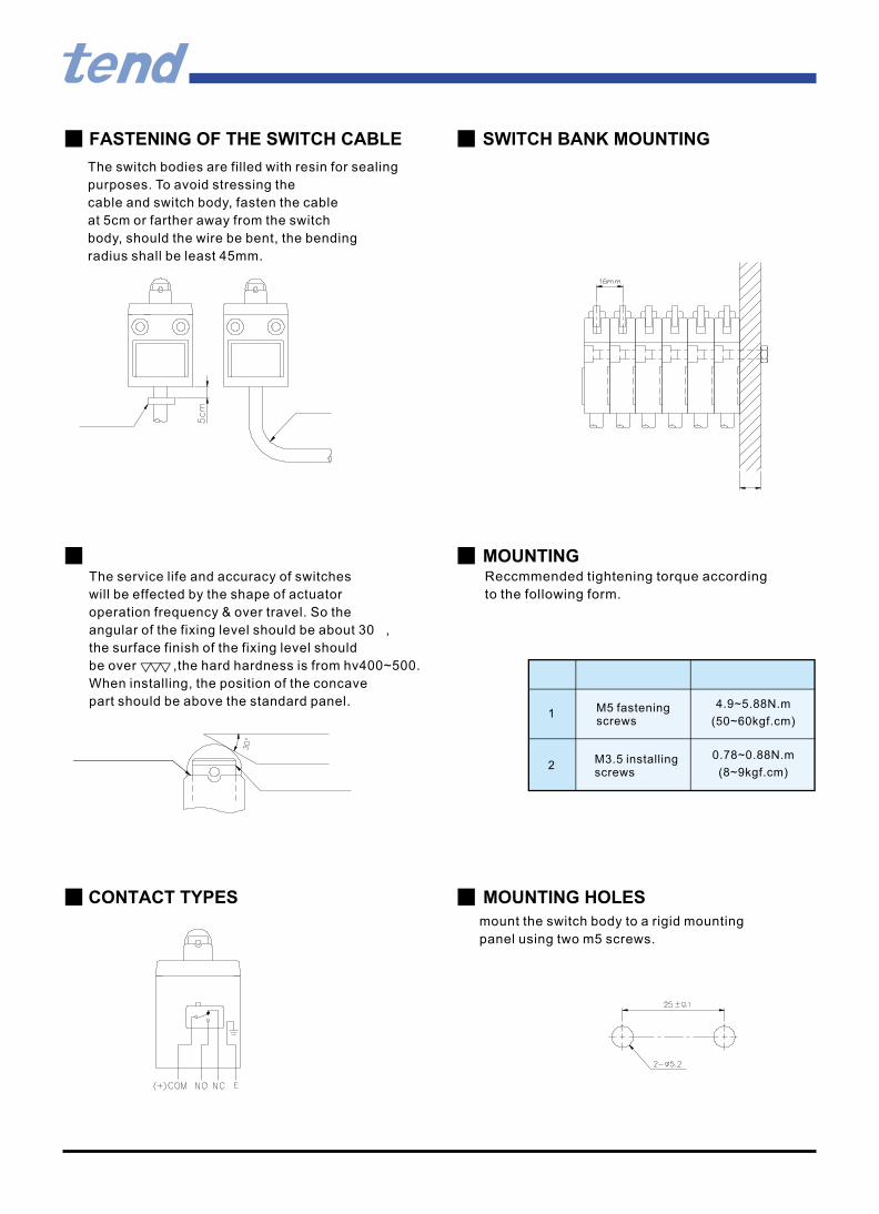
MOUNTING
Reccmmended tightening torque according
to the following form.
FASTENING OF THE SWITCH CABLE
The switch bodies are filled with resin for sealing
purposes. To avoid stressing the
cable and switch body, fasten the cable
at 5cm or farther away from the switch
body, should the wire be bent, the bending
radius shall be least 45mm.
SWITCH BANK MOUNTING
CONTACT TYPES
mount the switch body to a rigid mounting
panel using two m5 screws.
MOUNTING HOLES
M5 fasteningscrews
1
0.78~0.88N.mM3.5 installingscrews
2(8~9kgf.cm)
(50~60kgf.cm)
4.9~5.88N.m
The service life and accuracy of switches
will be effected by the shape of actuator
operation frequency & over travel. So the
angular of the fixing level should be about 30 ,
the surface finish of the fixing level should
be over ,the hard hardness is from hv400~500.
When installing, the position of the concave
part should be above the standard panel.

90° operation on one side is possible by simply changing the direc- tion of the cam.
OVERTRAVEL TYPE
OF: Operating Force
RF: Releasing Force
TF: Total Force
FP: Free Position
OP: Operating Position
RP: Releasing Position
TTP: Total Travel Position
PT: Pretravel
OT: Overtravel
MD: Movement Differential
TT: Total travel
CONTACT CONFIGURATION
Loosen the cam holderwith a coin or screw driver

LIMIT SWITCH
TZ-5105TZ-5103 TZ-5135TZ-5125
TZ-5101
DIMENSIONS
TZ-5102
-2N SERIES
Basic type and-2 SERIESMounting holes
OPERATING CHARACTERISTICS
TB 9
TZ-5
1.7mm 20° 55°20°1.7mmmax.PT 20°
TTP max.
OP
min.OT 30°
max.MD 12°
44.8±0.8mm 90±10°34±0.8mm
30° 30° 35°5.6mm
1mm 12°12°
6.4mm
1mm
min.RF
max.OF 1,360g
Type TZ-5104
910g 28g227g
2,720g 1,360g 142g 1,200g
910g
2,720g
TZ-5102 TZ-5107TZ-5108 TZ-5105TZ-5101
1.7mm
41mm
4mm
1mm
910g
2,720g
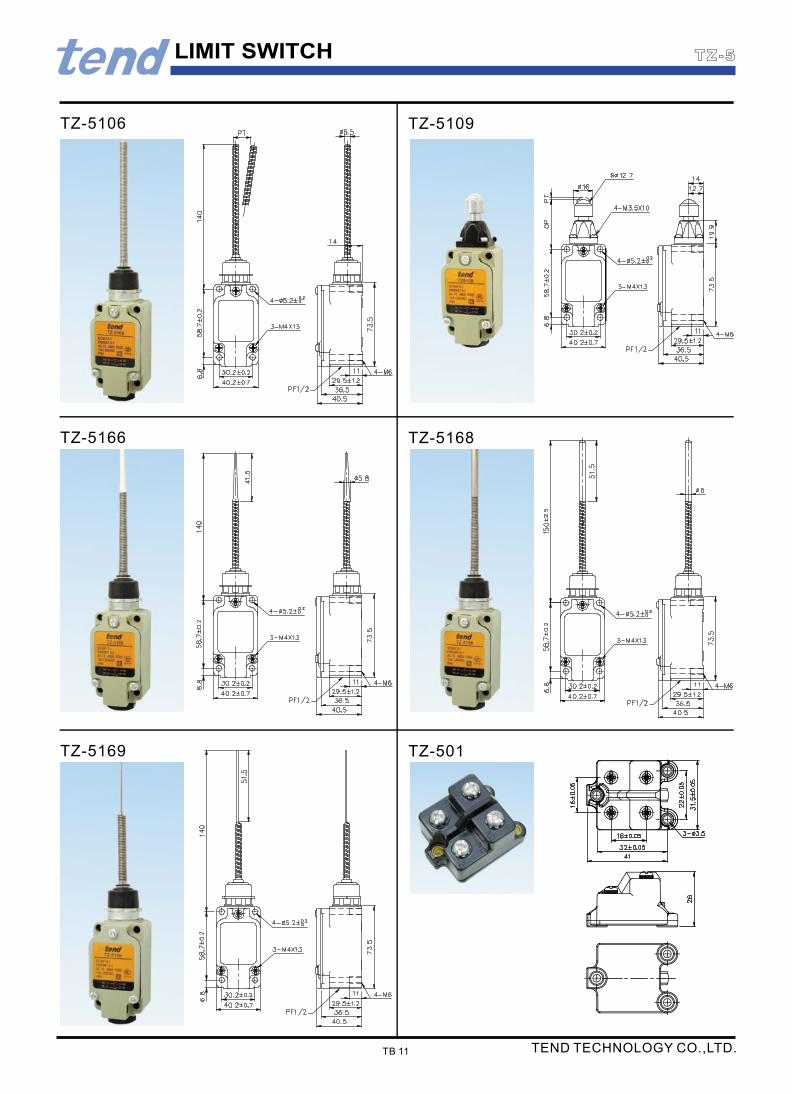
TZ-5109
max.PT
min.OT
max.MD
min.RF
max.OF
Type
150g
TZ-5106.5166.5168.5169
28mm
12°
100g
20°
55°
1000g
TZ-5104-2.5108-2
12° 10° 10°
25g25g 120g
20°20° 20°
70°55° 70°
290g 980g 290g
TZ-5107-2 TZ-5104-2N.5108-2N TZ-5107-2N
29.5mm
44.5±0.8mm
227g
39.5mm
TEND TECHNOLOGY CO.,LTD.
TZ-5125 TZ-5135
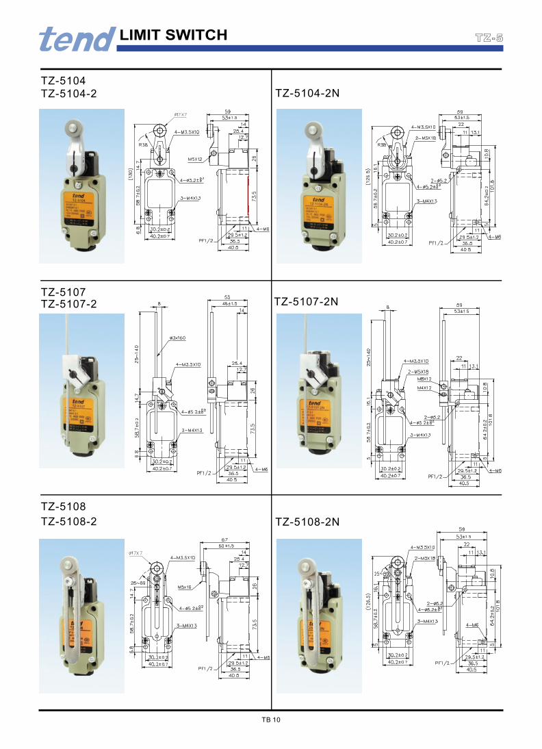
TZ-5108-2
TZ-5108
TZ-5108-2N
TZ-5107-2
TZ-5107
TZ-5104-2
TZ-5104
TZ-5107-2N
TZ-5104-2N
TZ-5
TB 10
LIMIT SWITCH
LIMIT SWITCH
TZ-5169 TZ-501
TZ-5166 TZ-5168
TZ-5106 TZ-5109
TB 11
TZ-5
TEND TECHNOLOGY CO.,LTD.
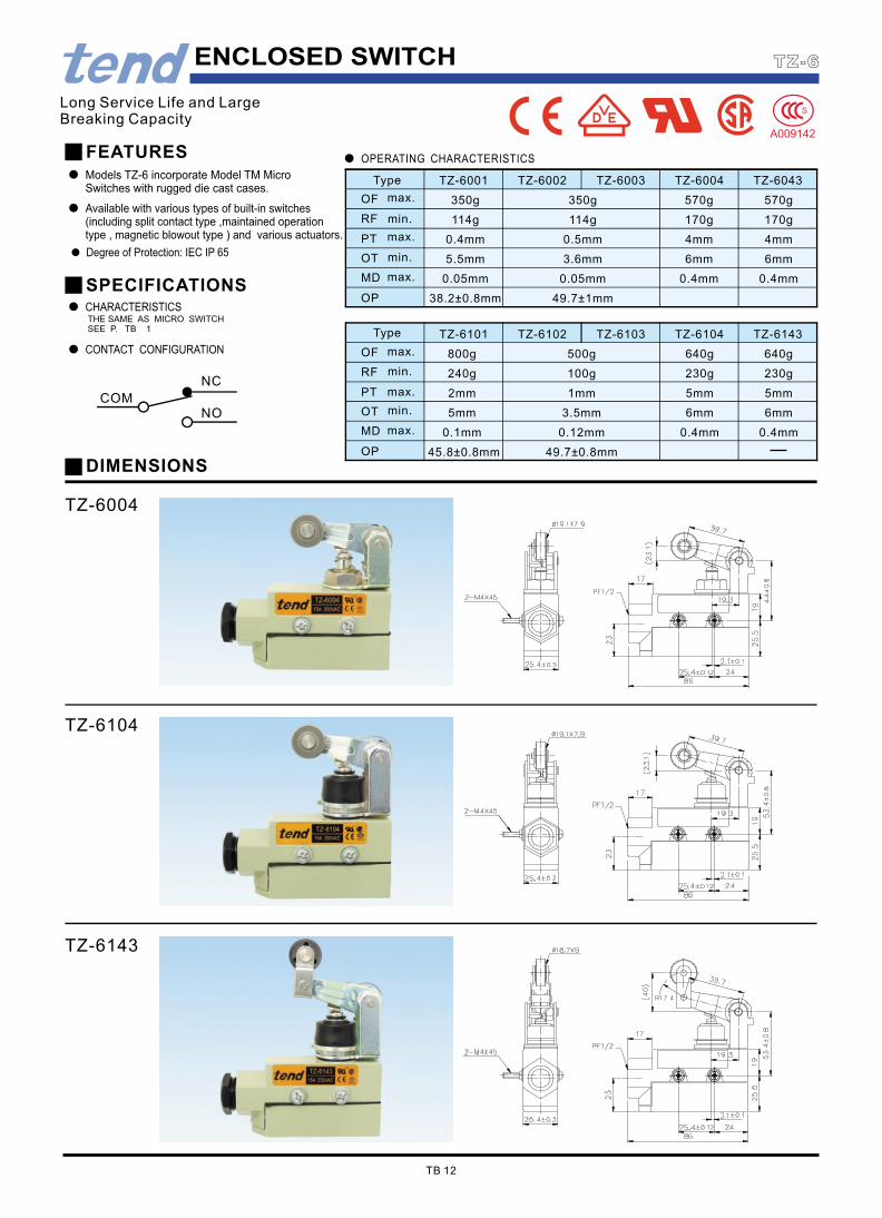
TZ-6143
TZ-6104
Models TZ-6 incorporate Model TM MicroSwitches with rugged die cast cases.
TZ-6004
DIMENSIONS
240g 230g230g100g
6mm3.5mm 6mm5mmOT
49.7±0.8mm45.8±0.8mmOP
0.12mmMD 0.1mm 0.4mm 0.4mm
5mm1mm 5mm2mmPT
RF
500g800gOF 640g 640g
TZ-6101 TZ-6102 TZ-6104TZ-6103 TZ-6143
49.7±1mm38.2±0.8mmOP
0.05mm0.05mmMD 0.4mm 0.4mm
170g114g 170g114gRF min.
PT
3.6mmOT 5.5mm 6mm 6mm
0.5mm0.4mm 4mm 4mm
350g 570g 570g350gOF
max.
TZ-6001Type TZ-6002 TZ-6004TZ-6003 TZ-6043
TB 12
TZ-6ENCLOSED SWITCH
SPECIFICATIONS
COM
NC
NO
FEATURES
Available with various types of built-in switches(including split contact type ,maintained operationtype , magnetic blowout type ) and various actuators.
Long Service Life and LargeBreaking Capacity
CHARACTERISTICS
CONTACT CONFIGURATION
OPERATING CHARACTERISTICS
Degree of Protection: IEC IP 65
max.
min.
max.
max.
max.
max.
Type
min.
min.
THE SAME AS MICRO SWITCHSEE P. TB 1
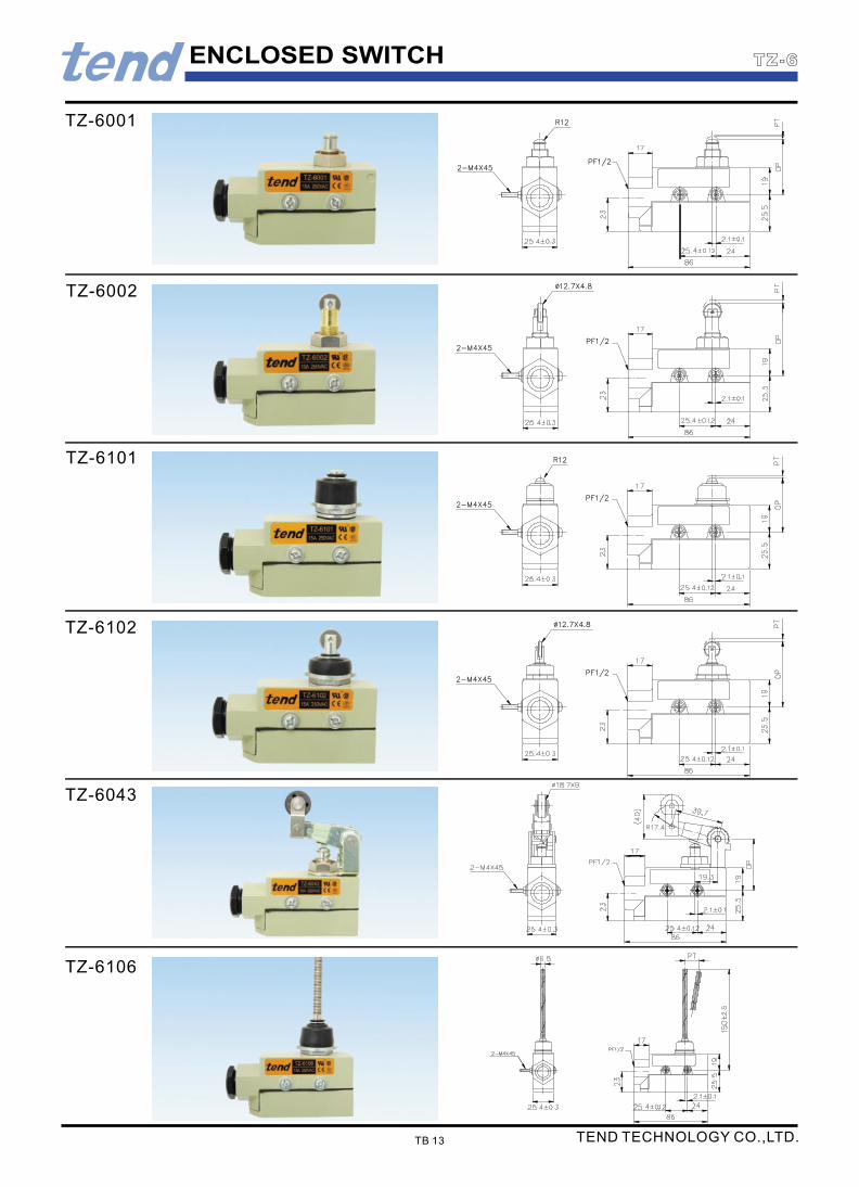
ENCLOSED SWITCH
TZ-6043
TZ-6106
TZ-6102
TZ-6101
TZ-6002
TZ-6001
TB 13
TZ-6
TEND TECHNOLOGY CO.,LTD.

21.8±1.2mm 33.3±1.2mm
TZ-7141
46mm35mm35mm 56mm
1.5mm 2.4mm 1.5mm2.0mm 2.4mm3.2mm
40±1mm25±1mm 25±1mm 40±1mm 50±1.2mm 50±1.2mm
TZ-7312
2.0mm2.0mm 2.0mm 2.0mm 2.0mm
100g 100g100g 100g100g
600g 600g600g 600g600g
TZ-7100 TZ-7310 TZ-7311TZ-7110
6.5mm 11mm 6.5mm 25mm13.5mm 8.5mm 11.0mm
80g60g 50g40g 60g 100g
240g220g 180g150g 120g200g 280g
TZ-7141TZ-7140 TZ-7121TZ-7120 TZ-7166TZ-7124 TZ-7144
6 561.510 38 VDC
0.030.05
CONTACT CONFIGURATION
Notes: 1.inductive load: power factor=0.4;time constant =7msec. 2.lamp load has an inrush current of 10 time the steady-state current while motor load has an inrush current of 6 times the steady-sate current.
0.2 0.030.25250 VDC
58 3 61.530 VDC0.5125 VDC 0.4 0.05
1014 VDC 661.53
Operating:-10 to +80°C
Approx.60g
Electrically
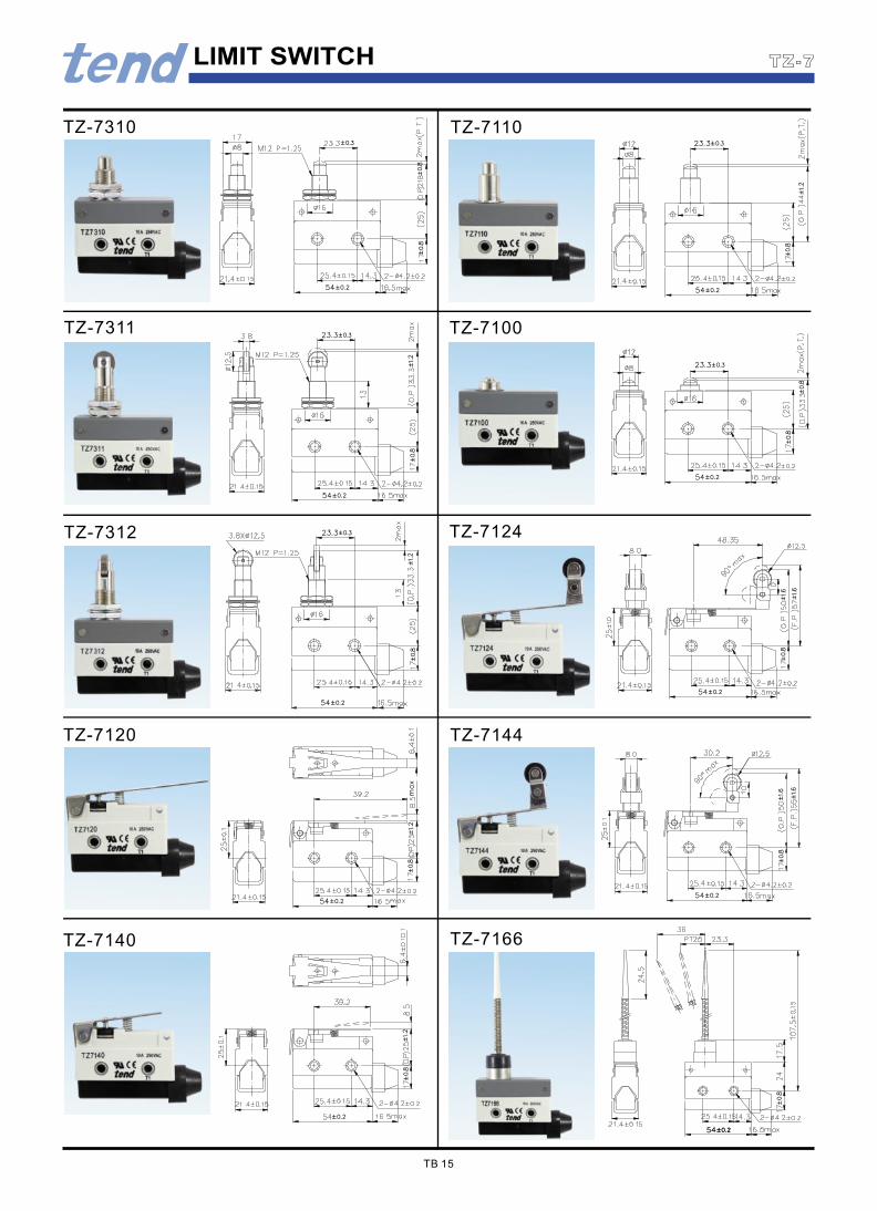
LIMIT SWITCH
TZ-7140 TZ-7166
TZ-7120 TZ-7144
TZ-7312 TZ-7124
TZ-7311 TZ-7100
TZ-7310 TZ-7110
TB 15
TZ-7
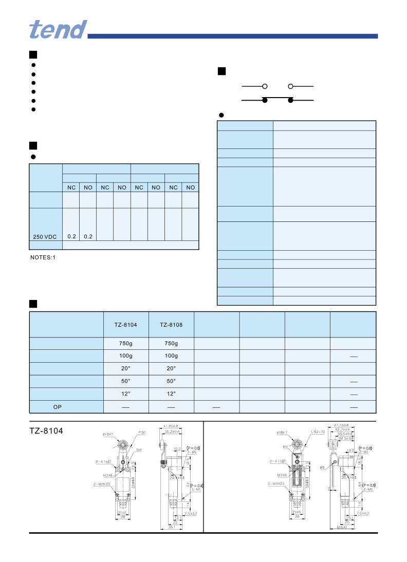
TZ-8104
OP
12°12°
50°50°
20°20°
100g100g
750g750g
TZ-8108TZ-8104
NONCNONC NC NONONC
0.2 0.2250 VDC
NOTES:1
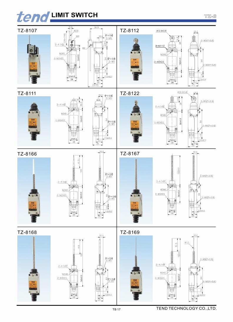
LIMIT SWITCH
TZ-8112
TZ-8169TZ-8168
TZ-8166 TZ-8167
TZ-8111 TZ-8122
TZ-8107
TB 17
TZ-8
TEND TECHNOLOGY CO.,LTD.
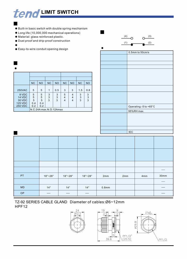
LIMIT SWITCH
30mm4mm2mm18°~28° 2mm18°~28°18°~28°PT
HPF12
TZ-92 SERIES CABLE GLAND Diameter of cables:Ø6~12mm
14°14°14° 0.8mm
OP
MD
Long life (10,000,000 mechanical operations)
Material: glass reinforced plastic.
Dust proof and drip-proof construction
Built-in basic switch with double spring mechanism
(2)(1)
(4) (3)
0.5mm to 50cm/s
Easy-to-wire conduit opening design
NONONCNONC NC NC NO
8 VDC 535 35 34 3
35 15 0.5 0.83 1.5
95%RH max.
Operating:-5 to +65°C
43 4 3 3514 VDC 35
30 VDC
250 VDC125 VDC 0.40.4
0.20.2
435 35 34 3
250VAC
N.C:24A max.N.O:12Amax
IEC
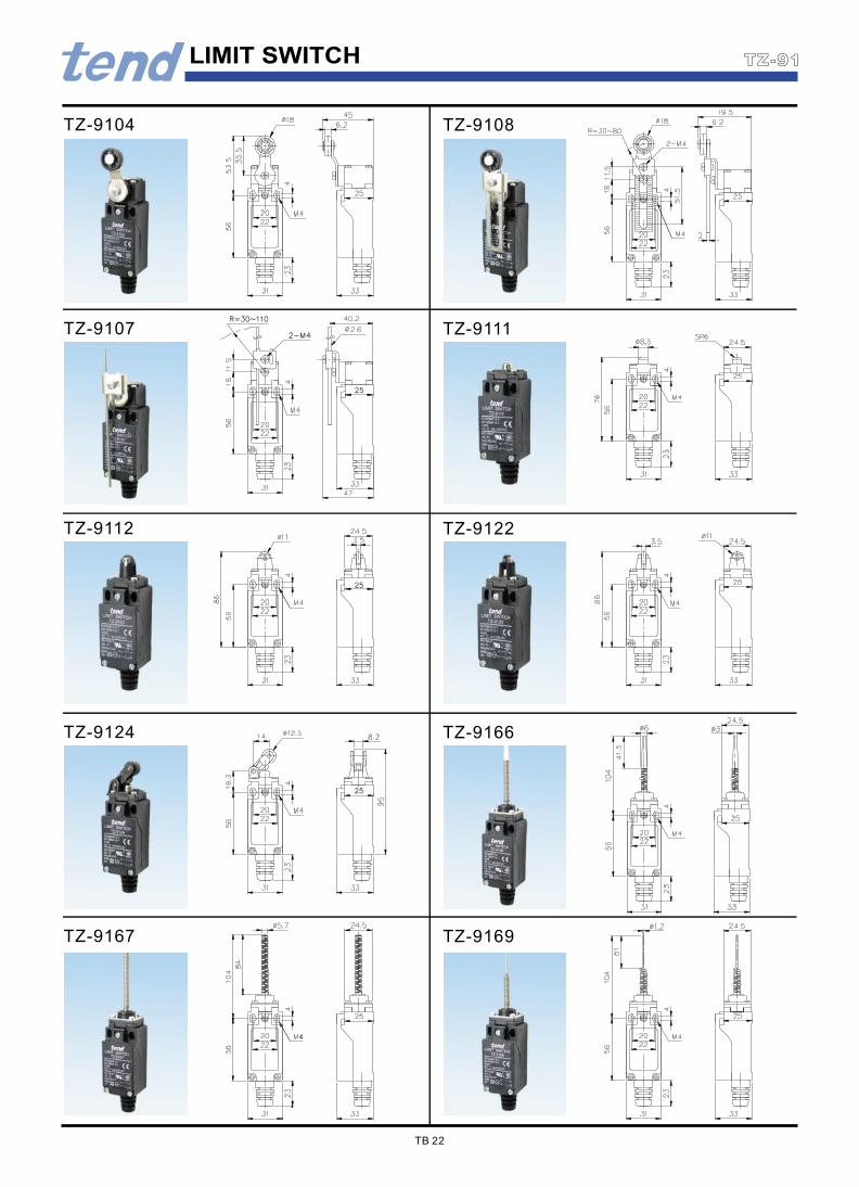
TZ-9169TZ-9167
TZ-9124 TZ-9166
TZ-9112 TZ-9122
TZ-9107 TZ-9111
TZ-9104 TZ-9108
TB 22
TZ-91LIMIT SWITCH
LIMIT SWITCH
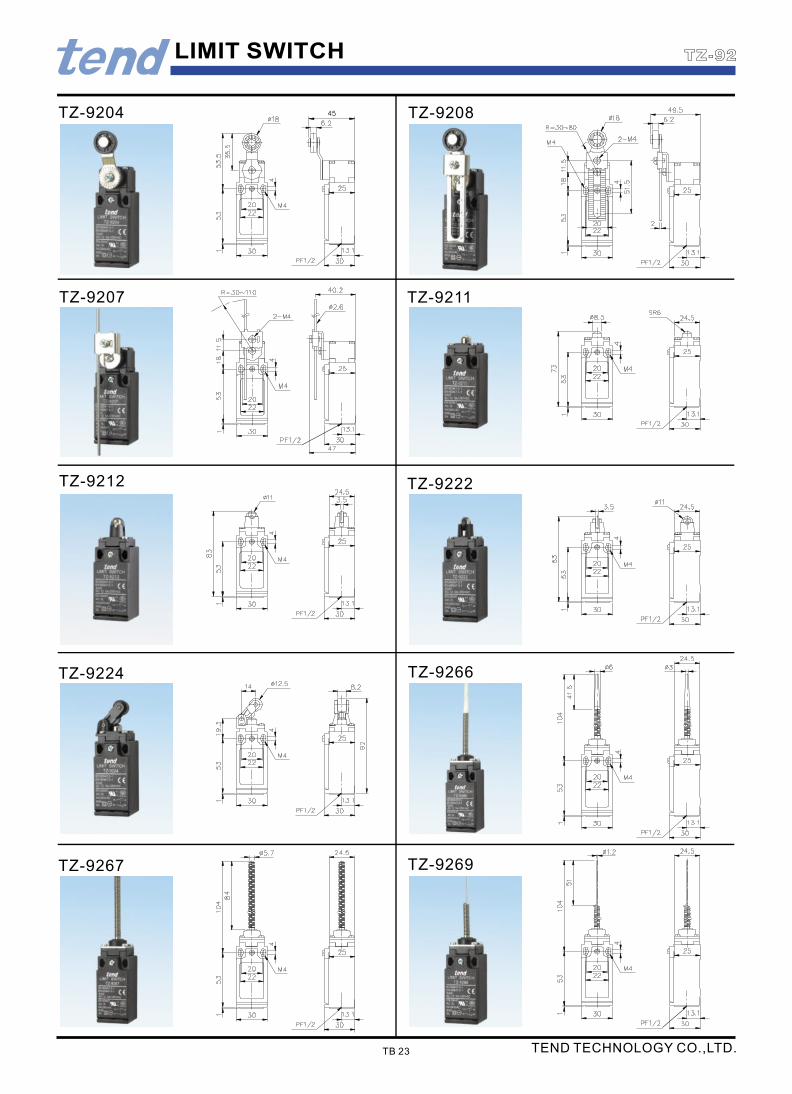
TZ-9204 TZ-9208
TZ-9266TZ-9224
TZ-9222TZ-9212
TZ-9211TZ-9207
TZ-9269TZ-9267
TB 23
TZ-92
TEND TECHNOLOGY CO.,LTD.

Inductive loadLamp loadResistive load Motor load
USE ATTENTION AFFAIR
When in use, there should put a plate on the top to preventthe key overinsert. To prevent nonmovement, the space between the plate and the switch should be under 3 mm.
To prevent the wear and the space should be within 1 mm between the key and middle of the insert hole.
610361014VDC
0.10.40.10.10.4250VDC
4634630VDC
0.20.20.8125VDC 0.20.8
125VAC
1.530.81.510400VAC 0.8
36108VDC 610
1210250VAC 310 1.5
NCNC NONCNCNONC NO
1.5310 510 2.5
When the contact block get fire, press on the middle ofthe key structure, the Nc strict leaving structure can push the contact block a way cut off the movement.
Mechanically

SAFETY KEY INTERLOCK SWITCH
TZ-93BPG02TZ-93BPG01TZ-93BPT02TZ-93BPT01
TZ-93CPG01 TZ-93CPG02
DIMENSIONS OF OPERATING
TZ-93BPG03TZ-93BPT03TZ-93CPG03
(28mm)Total travel
10mmPositive opening travel
58.84N(6,000gf)min.Force reguiredto have positive
Key pull out force
max.
6±3mmPre travel
29.42N(3,000gf)
14.71N(1,500gf)Key plug in force
DIMENSIONS
TZ-93BPT
TZ-93CPGTZ-93CPT
TZ93-K2TZ93-K1
TYPE OF KEYS AND DIMENSIONS
TZ93-K3
OPERATING CHARACTERISTICS
TZ-93CPT03TZ-93CPT02TZ-93CPT01
TZ-93BPG
TB 25
TZ-93
TEND TECHNOLOGY CO.,LTD.
max.
min.