Instructions for use
Title Bending resistance of repaired column members and shear resistance of opening frames with repaired columns ofconventional Japanese wooden houses
Author(s) Sawata, Kei; Toda, Masahiko; Kanetaka, Satoru; Sasaki, Yoshihisa; Hirai, Takuro
Citation Journal of Wood Science, 57(6), 536-541https://doi.org/10.1007/s10086-011-1204-z
Issue Date 2011-12
Doc URL http://hdl.handle.net/2115/47555
Rights The original publication is available at www.springerlink.com
Type article (author version)
File Information JWS57-6_536-541.pdf
Hokkaido University Collection of Scholarly and Academic Papers : HUSCAP

1
Title: Bending resistance of repaired column members and shear resistance of opening frames with
repaired column of Japanese conventional wooden houses
Type of article: Note
Author’s name: Kei Sawata, Masahiko Toda, Satoru Kanetaka, Yoshihisa Sasaki, Takuro Hirai
Kei Sawata (corresponding author), Yoshihisa Sasaki, Takuro Hirai
Graduate School of Agriculture, Hokkaido University, N9 W9, Sapporo 060-8589, Japan
E-mail: [email protected]
TEL: +81 11-706-2528, FAX: +81 11-706-3636
Masahiko Toda
Forest Products Research Institute, Hokkaido Research Organization, Asahikawa 071-0198, Japan
Satoru Kanetaka
Akita Wood Technology Transfer Foundation, Noshiro 016-0876, Japan
Keywords: End-joint, Bending test, Racking test, Conventional frame, Plywood-sheathed frame
Footnote: Part of this report was presented at the 59th Annual Meeting of the Society of Materials
Science, Hokkaido, May 2010; and the Annual Meeting of the Architectural Institute of Japan, Toyama,
September 2010
2
Abstract
In many cases of repairing Japanese conventional wooden houses, decayed lower parts of columns should
be replaced with new wood material. Bending resistance of columns repaired by four methods and shear
resistance of opening frames with those repaired columns were investigated in this study. Bending tests of
the repaired columns showed differences in initial bending stiffness and maximum bending moment among
the combinations of repair methods and loading directions. Racking tests were conducted on door opening
frames with conventional door head member or upper partial walls sheathed with 12mm thick plywood.
The conventional frame specimens broke at door head-column joints with no obvious bending deformation
of the columns, it resulted in little difference in load-shear deformation curves among the repair methods.
The columns of plywood-sheathed specimens, on the other hand, were bent clearly after when the nails at
the plywood to wood frame joints started to be pulled off. The load-shear deformation curves of the
plywood-sheathed specimens did not vary regardless of the repair methods in small shear deformations, but
affected by the repair methods as shear deformations increased.
Keywords
End-joint, Bending test, Racking test, Conventional wood frame, Plywood-sheathed frame

3
Introduction
Structural performance of timber constructions is degraded by some factors throughout their service
periods1-2
. Biological factors, wood fungi and termite, particularly bring about the timber constructions the
risk of significant damages under high moisture condition. To recover the safety and serviceability of
damaged constructions, deteriorated wood members should be removed and replaced with new wood
materials.
Several studies have been reported on repair method for deteriorated members up to the present, in
which mortise and tenon joints3, mechanical joints
4-5 and adhesive joints
6-8 were examined.
However, practical data of the lateral resistance of repaired wooden frames of Japanese
conventional wooden houses have not been accumulated enough to prepare design basis for various repair
methods at present. In many cases of repairing Japanese conventional wooden houses, lower parts of
columns often need to be replaced with new wood material because of high probability of biological
deterioration. This study focused on bending resistance of columns repaired by four methods, which were
called as netsugi joint in Japanese, and lateral resistance of opening frames with the repaired columns.
Materials and methods
Bending tests of wood members
Bending specimens were prepared from sugi (Cryptomeria japonica) with cross section of 105mm x
105mm. The average wood density was 411kg/m3 (standard deviation, 34.9kg/m
3) and the average moisture
content was 16.5% (standard deviation, 4.55%). Four points bending tests were conducted on the following
specimens. Configuration of types B, C, D and E are shown in Fig. 1.

4
Type A: specimens without end-joint.
Type B: specimens with glued-in hardwood dowels. Test members were end-jointed using 4 keyaki
(Zelkova serrata) dowels with epoxy resin adhesive. The dowel was 21mm in diameter and 300mm in
length and lead hole of the member was 22mm in diameter and 155mm in depth.
Type C: specimens end-jointed with 2 bolts and 20 nails. The bolt diameter was 12mm. Column members
and 12mm thick structural softwood plywood were connected with CN90. Type C was separated types Ca
and Cb according to loading direction.
Type D: specimens having Japanese traditional tenon-mortise joint called for kanawatsugi. Cotter pin of
this joint was keyaki. Type D was separated types Da and Db according to loading direction.
Type E: specimens end-jointed with 2 steel clamps (C120). The clamp was 6mm in diameter, 45mm in
driven length and 120mm in length. Type E was separated types Ea and Eb according to loading direction.
The bending tests were conducted on 6 specimens per each combination of joint type and loading
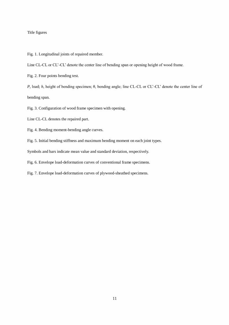
direction, which resulted in 48 specimens in total. The specimens were tested in four points bending with
the bending span of 18 times the specimen height (h), in which the distance between the loading points was
6h (types A, B, D and E) or 8h (type C) shown in Fig. 2(a).
Bending deflection at center of specimen is generally measured in bending test. However,
measurement of the deflection may be difficult depending on configuration of specimens with repaired part
because of sliding or opening at end-joint (Fig. 2(b) or (c)). In this, deflection of the specimen at two
loading points was measured with two displacement transducers and bending angle of specimen (Fig. 2(d))
was obtained from two measured deflections as follows:
SL
)(2 21 (1)
where θ is bending angle (rad.), δ1 andδ2 are deflection (mm) measured by displacement transducers
shown in Fig. 2(d), L is bending span (mm), S is the distance between the loading points (mm).
Racking tests of opening frames

5
Dimensions of frame specimens were 1820mm length and 2700mm height with an opening 1800mm in
height shown in Fig. 3. The frame specimens consisted of 105mm x 105mm columns, a sill and a beam of
sugi solid lumber. Those members were connected with T-type steel plates (CP-T).
Racking tests were conducted on Japanese conventional door opening frames or upper partial walls
sheathed with 12mm thick larch plywood. The conventional frames had 240mm x 105mm sugi door head.
The door head and the columns were connected with 15mm x 15mm mizunara (Quercus crispula) cotter
pin. The plywood-sheathed specimens had 45mm x 105mm sugi door head that was connected to the
columns with four CN65 nails. The plywood was connected to the frame members with CN50 nails at
150mm spacing.
The frame specimens had column without or with end-joint (types A, B, Ca, Da and Ea in Fig. 1).
The repaired part was positioned the center of opening height. The racking tests were conducted on 3
specimens per each combination of frame type and joint type, which resulted in 30 specimens in total.
Air-dried density and moisture content were obtained from the inside of column member after
racking tests. The average density of columns was 410kg/m3 (standard deviation, 46.7kg/m
3). The moisture
content of 2 columns was 93.2% and 51.5% and the other average moisture content was 16.3% (standard
deviation, 3.63%), provided that the effects of measured moisture content for shear resistance were not
observed in this study. Moisture content of the repaired part may be low than above values (93.2% and
51.5%) because the transverse section of repaired member was exposed to room air.
A sill of frame specimen was connected to steel foundation with 4 bolts of 16mm diameter. Two
hold-down connections (BHU-20) were installed at ends of the frame. Step of the cyclic loading test was
repeated three times to produce 1/450, 1/300, 1/200, 1/150, 1/100, 1/75 and 1/50rad of shear deformation.
And then the frame specimens were loaded monotonically until shear deformation was more than 1/15rad9.

6
Results and discussion
Difference in bending resistance among repair methods
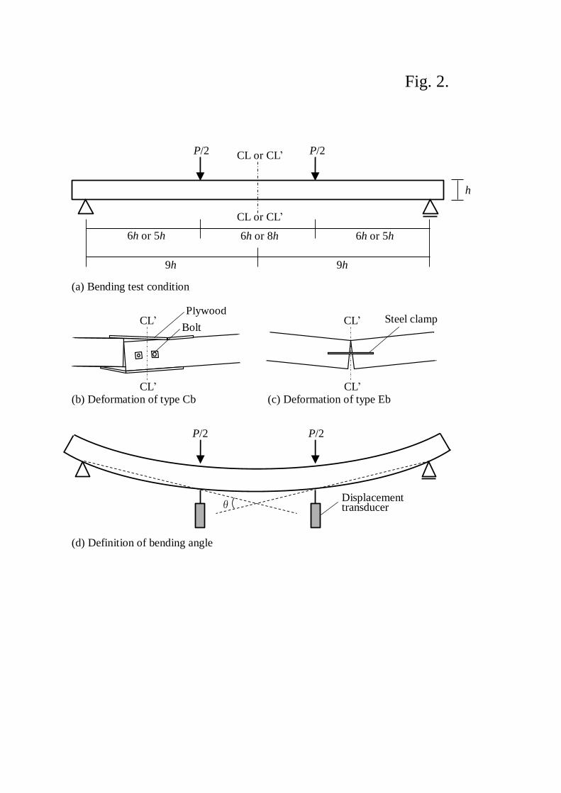
Fig. 4 shows bending moment-bending angle curves obtained from bending tests. Shapes of bending
moment-bending angle curves varied clearly according to joint types. The bending moment of type A was
increased up to 5.5-11.9kNm, but the maximum bending moment of other types were less than 4kNm.
Initial bending stiffness and maximum bending moment were obtained from the moment-bending angle
curves. Initial bending stiffness was defined as the line that passes through points on the curves
corresponding to 10% and 40% of the maximum bending moment.
Fig. 5 shows the initial bending stiffness and the maximum bending moment of each joint type. The
initial bending stiffness differed noticeably depending on joint types and loading directions. Type B showed
the highest initial bending stiffness of those repair methods and its initial bending stiffness was 77% of the
control specimen (type A) in average. Type Eb showed the lowest values and its initial bending stiffness
was 12% of the control specimen in average. The initial bending stiffness of joint types Ca and Cb was
observed difference due to loading direction, and that of type Ca was 68% of that of type Cb. However, the
other was not clear the effect of loading direction on the initial bending stiffness because types Db and Ea
had large standard deviation.
The maximum bending moments of the repaired member on each joint type had small standard
deviation, and were 4.6% to 40% of the control specimen in average. The maximum bending moment
differed with the combination of joint type and loading direction. The maximum bending moment of types
Ca and Ea were similar to that of types Cb and Eb, and the former were 94 % and 114% of the latter,
respectively. In contrast, the maximum bending moment of type Da showed about two times higher value
than type Db.
7
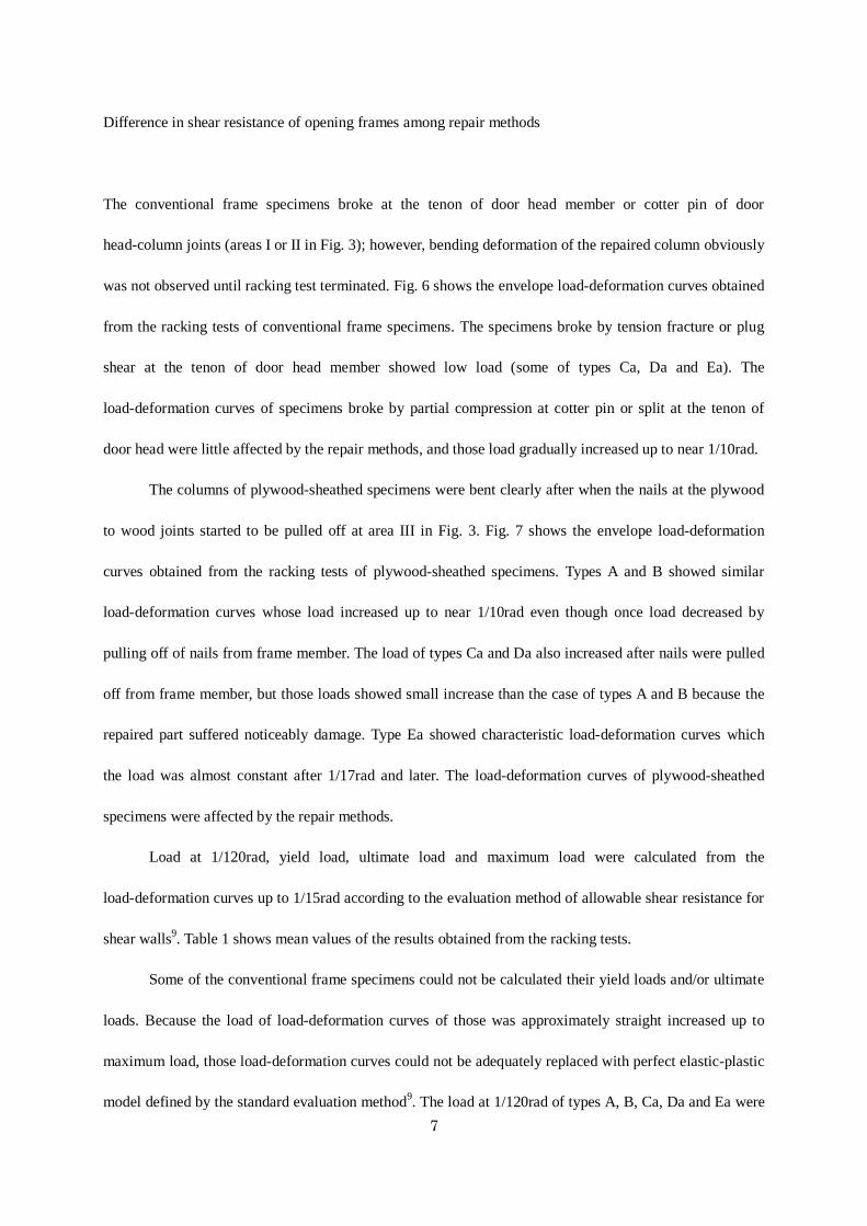
Difference in shear resistance of opening frames among repair methods
The conventional frame specimens broke at the tenon of door head member or cotter pin of door
head-column joints (areas I or II in Fig. 3); however, bending deformation of the repaired column obviously
was not observed until racking test terminated. Fig. 6 shows the envelope load-deformation curves obtained
from the racking tests of conventional frame specimens. The specimens broke by tension fracture or plug
shear at the tenon of door head member showed low load (some of types Ca, Da and Ea). The
load-deformation curves of specimens broke by partial compression at cotter pin or split at the tenon of
door head were little affected by the repair methods, and those load gradually increased up to near 1/10rad.
The columns of plywood-sheathed specimens were bent clearly after when the nails at the plywood
to wood joints started to be pulled off at area III in Fig. 3. Fig. 7 shows the envelope load-deformation
curves obtained from the racking tests of plywood-sheathed specimens. Types A and B showed similar
load-deformation curves whose load increased up to near 1/10rad even though once load decreased by
pulling off of nails from frame member. The load of types Ca and Da also increased after nails were pulled
off from frame member, but those loads showed small increase than the case of types A and B because the
repaired part suffered noticeably damage. Type Ea showed characteristic load-deformation curves which
the load was almost constant after 1/17rad and later. The load-deformation curves of plywood-sheathed
specimens were affected by the repair methods.
Load at 1/120rad, yield load, ultimate load and maximum load were calculated from the
load-deformation curves up to 1/15rad according to the evaluation method of allowable shear resistance for
shear walls9. Table 1 shows mean values of the results obtained from the racking tests.
Some of the conventional frame specimens could not be calculated their yield loads and/or ultimate
loads. Because the load of load-deformation curves of those was approximately straight increased up to
maximum load, those load-deformation curves could not be adequately replaced with perfect elastic-plastic
model defined by the standard evaluation method9. The load at 1/120rad of types A, B, Ca, Da and Ea were

8
0.47, 0.81, 0.52, 0.60 and 0.70, respectively, there are differences among specimen types. But this
difference may be caused by the degree of fixation between door head-column joints because damage was
little observed in the repaired part until racking test terminated. The maximum load of types B, Ca, Da and
Ea were 92% to 109% of type A in average, and the differences between the former and the latter were not
significant at 95% confidence level.
In the case of the plywood-sheathed specimen, the load at 1/120rad of types B, Ca, Da and Ea were
90% to 107% of type A in average, the differences between the former and the latter were not significant at
95% confidence level. The maximum loads of types B, Ca, Da and Ea were 88%, 93%, 94% and 78% of
type A in average, respectively, and the only the difference between types A and Ea were significant at 95%
confidence level.
Conclusions
The bending tests and the racking tests conducted on column members repaired by four methods and
opening frames with those repaired columns, respectively. The obtained results can be summarized as
follows:
1. Initial bending stiffness and maximum bending moment of repaired column member are noticeably
affected by combination of repair methods and loading directions.
2. Although the bending resistance of column member is largely changed by the repair methods, the
shear resistance of conventional frames with repaired column is little affected by the repair methods.
3. The shear resistance of plywood-sheathed frames with repaired column is little affected by the repair
methods in small shear deformation, but is affected by the repair methods as shear deformation
increase.
4. The shear resistance of opening frames with repaired column is dependent on combination of

9
configuration of frame and repair method.
Acknowledgements
This research was supported by the project of prototype design committee of Japan Housing and Wood
Technology Center.

10
References
1. Hikita Y, Furumoto M, Nishimoto K (1989) The management and maintenance of homes against
damage: I. In the case of wooden houses (in Japanese). Mokuzai Gakkaishi 35:90-99
2. Hikita Y, Taniguchi M (1992) Management and maintenance of homes against damage: II. A case of
old traditional wooden houses (in Japanese). Mokuzai Gakkaishi 38:869-875
3. Kato Y, Kawakami K (1984) Methods of repairing and changing for wooden construction (in
Japanese). In: Summaries of Technical Papers Annual Meeting of the Architectural Institute of Japan
structure system:295-296
4. The Japan Termite Control Association (1998) Decay diagnosis and repair method for timber building
(in Japanese). The Japan Termite Control Association, Tokyo
5. The Japan Building Disaster Prevention Association (2004) Seismic performance evaluation and
strengthening method for timber houses (in Japanese). Japan Building Disaster Prevention Association,
Tokyo
6. Van Gemert D, Vanden Bosch M (1987) Structural restoration of wooden beams by means of epoxy
resin. Materials and Structures 20:165-170
7. Sasaki T, Koizumi A, Jensen JL, Iijima Y, Komatsu K (2002) End joint with glued-in hardwood
dowels in timber construction. II: Bending properties of beams jointed with multiple rows of dowels
(in Japanese). Mokuzai Gakkaishi 48:23-31
8. Duarte A, Negrao J, Cruz H, Balseiro A (2008) Bending strength of timber beams rehabilitated with
reinforced epoxy mortar plates. Journal of Structural Engineering 134:792-800
9. Japan Housing and Wood Technology Center (2008) Allowable stress design for wooden post and
beam construction houses (in Japanese). Japan Housing and Wood Technology Center, Tokyo
11
Title figures
Fig. 1. Longitudinal joints of repaired member.
Line CL-CL or CL’-CL’ denote the center line of bending span or opening height of wood frame.
Fig. 2. Four points bending test.
P, load; h, height of bending specimen; θ, bending angle; line CL-CL or CL’-CL’ denote the center line of
bending span.
Fig. 3. Configuration of wood frame specimen with opening.
Line CL-CL denotes the repaired part.
Fig. 4. Bending moment-bending angle curves.
Fig. 5. Initial bending stiffness and maximum bending moment on each joint types.
Symbols and bars indicate mean value and standard deviation, respectively.
Fig. 6. Envelope load-deformation curves of conventional frame specimens.
Fig. 7. Envelope load-deformation curves of plywood-sheathed specimens.

Fig. 1.
CL
60
25 25
1
00
1
00
1
00
1
00
300
1
05
1
05
2
5
30
3
0
37.5
15
1
5
1
8
2
4
5
0
45 15
45 15
CL CL
CL CL CL
CL
CL CL’ CL’ CL’
CL’ CL’
CL’
CL’
CL’
Dowel
φ21×300
Plywood
CN90
@100
Bolt
2-M12
Clamp
2-C120 Cotter pin
Loading direction a
Type Ca
Loading direction b
Type Cb
a a a b b b
Loading direction a
Type Da
Loading direction b
Type Db
Loading direction a
Type Ea
Loading direction b
Type Eb
Type B
[Unit: mm]
6h or 5h
(a) Bending test condition
6h or 5h 6h or 8h
9h 9h
P/2 P/2 CL or CL’
CL or CL’
(b) Deformation of type Cb (c) Deformation of type Eb
CL’
CL’
CL’
CL’
P/2 P/2
θ
(d) Definition of bending angle
Displacement transducer
Fig. 2.
h
Steel clamp Plywood
Bolt

Fig. 3.
80
CL CL CL CL
20
65 40
20
30
1
20
120
Area I Area II
Details of areas I and II
Area III
Tenon (70×70×30)
T-shape fastener
CP-T
T-shape fastener
CP-T
Cotter pin (15×15×105)
CN50@150
T-shape fastener CP-T
on the opposite side
(a) Conventional wood frame specimen (b) Plywood-sheathed specimen
Monotonic loading direction after cyclic loading
[Unit: mm]
Fig. 4.
0
1
2
3
4
5
-0.05 0.05 0.15 0.25
Mom
ent(
kN
m)
Bending angle(rad.)
0
1
2
3
4
5
-0.05 0.05 0.15 0.25
Mom
ent(
kN
m)
Bending angle(rad.)
0
1
2
3
4
5
-0.05 0.05 0.15 0.25
Mom
ent(
kN
m)
Bending angle(rad.)
0
5
10
15
-0.05 0.05 0.15 0.25
Mo
men
t(k
Nm
)
Bending angle(rad.)
0
1
2
3
4
5
-0.05 0.05 0.15 0.25
Mo
men
t(k
Nm
)
Bending angle(rad.)
0
1
2
3
4
5
-0.05 0.05 0.15 0.25
Mo
men
t(k
Nm
)
Bending angle(rad.)
0
1
2
3
4
5
-0.05 0.05 0.15 0.25
Mo
men
t(k
Nm
)
Bending angle(rad.)
0
1
2
3
4
5
-0.05 0.05 0.15 0.25
Mom
ent (k
Nm
)
Bending angle(rad.)
Mom
ent (k
Nm
)
Type Da Type Ea Type Db Type Eb
Type A Type B Type Ca Type Cb
Mom
ent (k
Nm
)
Bending angle (rad)

Fig. 5.
0
2
4
6
8
10
12
0
20
40
60
80
100
A B Ca Cb Da Db Ea Eb
Max
imu
m b
end
ing
mo
men
t (k
Nm
)
Init
ial b
end
ing
sti
ffn
ess
(kN
m/r
ad)
Joint type
Initial bending stiffness
Maximum bending moment
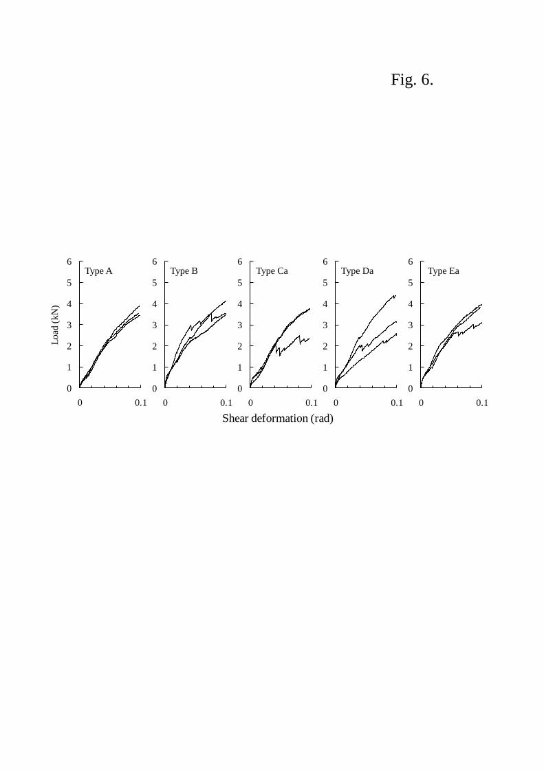
Fig. 6.
0
1
2
3
4
5
6
0 0.1L
oad
rad
0
1
2
3
4
5
6
0 0.1
Lo
ad
rad
0
1
2
3
4
5
6
0 0.1
Lo
ad
rad
0
1
2
3
4
5
6
0 0.1
Lo
ad
rad
0
1
2
3
4
5
6
0 0.1
Load
(kN
)
rad
Type A Type B Type Ca Type Da Type Ea
Shear deformation (rad)

Fig. 7.
0
1
2
3
4
5
6
0 0.1
Lo
adrad
0
1
2
3
4
5
6
0 0.1
Lo
ad
rad
0
1
2
3
4
5
6
0 0.1
Lo
ad
rad
0
1
2
3
4
5
6
0 0.1
Lo
ad
rad
0
1
2
3
4
5
6
0 0.1
Lo
ad (
kN
)
rad
Type A Type B Type Ca Type Da Type Ea
Shear deformation (rad)
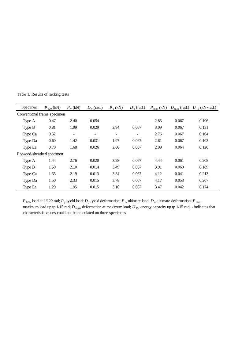
Table 1. Results of racking tests
P 120 (kN) P y (kN) D y (rad.) P u (kN) D u (rad.) P max (kN) D max (rad.) U 15 (kN・rad.)
Conventional frame specimen
Type A 0.47 2.40 0.054 - - 2.85 0.067 0.106
Type B 0.81 1.99 0.029 2.94 0.067 3.09 0.067 0.131
Type Ca 0.52 - - - - 2.76 0.067 0.104
Type Da 0.60 1.42 0.031 1.97 0.067 2.61 0.067 0.102
Type Ea 0.70 1.68 0.026 2.68 0.067 2.99 0.064 0.120
Plywood-sheathed specimen
Type A 1.44 2.76 0.020 3.98 0.067 4.44 0.061 0.208
Type B 1.50 2.10 0.014 3.49 0.067 3.91 0.060 0.189
Type Ca 1.55 2.19 0.013 3.84 0.067 4.12 0.041 0.213
Type Da 1.50 2.33 0.015 3.78 0.067 4.17 0.053 0.207
Type Ea 1.29 1.95 0.015 3.16 0.067 3.47 0.042 0.174
P 120, load at 1/120 rad; P y, yield load; D y, yield deformation; P u, ultimate load; D u, ultimate deformation; P max,
maximum load up tp 1/15 rad; D max, deformation at maximum load; U 15, energy capacity up tp 1/15 rad; - indicates that
characteristic values could not be calculated on three specimens
Specimen