8.1 Chapter 8: Bending and Shear Stresses in Beams Introduction One of the earliest studies concerned with the strength and deflection of beams was conducted by Galileo Galilei. • Galileo was the first to discuss the bending strength of a beam. • Galileo became the founder of a new branch of science: the theory of the strength of materials. In the 16 th century, Galileo observed a cantilever beam subjected to a load at the free end. • Galileo based his theory only on considerations of statics. • Galileo’s theory did not recognize the idea of elasticity. • The idea of elasticity was presented by Robert Hooke a half century later. Flexure according to Galileo About 50 years after Galileo’s observations, Edme Mariotte, a French physicist, stated his observations. • Mariotte’s theory was also based on the concept of the fulcrum. • Mariotte reasoned that the lengthening of the longitudinal beam fibers would be proportional to the distance from the fulcrum. • Mariotte suggested the linear tensile stress distribution shown at the right. Flexure according to Mariotte

Welcome message from author
This document is posted to help you gain knowledge. Please leave a comment to let me know what you think about it! Share it to your friends and learn new things together.
Transcript

8.1
Chapter 8: Bending and Shear Stresses in Beams
Introduction
One of the earliest studies concerned with the strength and deflection of beams
was conducted by Galileo Galilei.
• Galileo was the first to discuss the bending strength of a beam.
• Galileo became the founder of a new branch of science: the theory of the
strength of materials.
In the 16th century, Galileo observed a cantilever beam subjected to a load at the
free end.
• Galileo based his theory only on
considerations of statics.
• Galileo’s theory did not recognize the
idea of elasticity.
• The idea of elasticity was presented by
Robert Hooke a half century later.
Flexure according to Galileo
About 50 years after Galileo’s observations, Edme Mariotte, a French physicist,
stated his observations.
• Mariotte’s theory was also based on the
concept of the fulcrum.
• Mariotte reasoned that the lengthening
of the longitudinal beam fibers would be
proportional to the distance from the
fulcrum.
• Mariotte suggested the linear tensile
stress distribution shown at the right.
Flexure according to Mariotte

8.2
Two centuries after Galileo’s initial beam theory, Charles-Augustin de Coulomb and
Louis-Marie-Henri Navier finally succeeded in finding the correct answer.
• In 1773, Coulomb discarded the
fulcrum concept and proposed the
triangular distribution of stress
shown at the right.
• In Coulomb’s theory, both the tensile
and compressive stresses have the
same linear distribution.
Flexure according to Coulomb
8.1 Flexural Strain
The accuracy of Coulomb’s theory is demonstrated by examining a simply supported
beam subjected to bending.
The theory is based on the following
assumptions.
• The beam is initially straight and
of constant cross section.
• The beam is elastic and has equal
moduli of elasticity in tension and
compression.
• The beam is homogeneous (i.e. the
beam must consist of the same
material throughout).
• A plane section before bending
remains a plane after bending.
For these assumptions to be strictly true, the following conditions must apply.
• The beam must be bent only with couples (no shear on transverse planes).
• The beam must be proportioned so that it will not buckle.
• The loads must be applied so that no twisting (torsion) occurs.

8.3
Consider a portion of the bent beam between sections a-a and b-b shown below.
• At a distance C above the bottom of the beam, the
longitudinal fibers undergo no change in length.
• The curved surface formed by these fibers is
referred to as the neutral surface, and the
intersection of this surface with any cross section
is called the neutral axis of the cross section.
• The neutral axis corresponds to the
centroidal axis of a cross section.
• Because the fibers along the neutral surface
undergo no change in length, there is no
strain and no stress in the fibers along the
neutral surface.
• All fibers on one side of the neutral surface
are compressed, and the fibers on the other
side of the neutral surface are in tension.
In developing the flexural stress equation, the assumption is made that all
longitudinal fibers have the same length initially before loading.
• The strain of any fiber is directly proportional to the distance of the fiber
from the neutral surface.
• Using Hooke’s law, the stress in any fiber is also directly proportional to the
distance of the fiber from the neutral surface.
• Stress levels in the fibers are limited to magnitudes within the proportional
limit of the material.
The flexural stress equation is based on the stress distribution shown in the
drawing below.
• The deformation at the neutral axis is zero after
bending; therefore, the stress at the neutral axis
(N.A.) is zero.
• At the top fiber, the maximum shortening
(compression) occurs resulting in the maximum
compressive stresses.
• At the bottom fiber, the maximum lengthening
(tension) occurs, resulting in the maximum tensile
stress.

8.4
8.2 Flexural (Bending) Stress Equation
The flexural stress equation is developed from the following.
• Equilibrium concepts.
• Coulomb’s concept of linearity of the stress distribution.
• Hooke’s law regarding the proportionality between strain and stress.
The internal bending stresses on a beam cross section are shown above.
• The notation on the figure is defined as follows.
cc = distance from neutral axis (N.A.) to the extreme compressive fiber
ct = distance from N.A. to the extreme tensile fiber
y = distance from neutral axis to some area ΔA
ΔA = small strip of area on the beam cross section
In general, the flexural stress equation can be expressed mathematically by the
following equation.
fb = My/I
where
fb = bending stress at the fiber
y = distance from the N.A. to the fiber
I = moment of inertia of the cross section about its centroidal (or N.A.) axis
M = bending moment at some point along the beam length

8.5
For design purposes, the flexural stress equation is expressed as
fb = Mc/I
where
fb = bending stress at the extreme fiber, top or bottom
c = distance from the N.A. to the extreme fiber
I = moment of inertia of the cross section about its centroidal (or N.A.) axis
M = maximum bending moment at some point along the beam length
Bending stress fb is directly proportional to the value c.
• The largest bending stress on a cross section is obtained by selecting the larger
c-value for an unsymmetrical cross section.
8.6
Example Problems - Bending Stress
Problem 8.2 (p. 379)
Given: Beam (4 x 12 S4S timber) loaded
as shown.
Fb = 1300 psi
Find: Maximum bending stress developed.
Is it safely designed?
Need to find the following.
• Maximum bending moment.
• Moment of inertia (Ix).
• Distance “c.”
Solution
Find the reactions at the supports.
∑MB = 0 = - 12 Ay + 2000 (8) – 400 (4) 2
12Ay = 16,000 – 3200 = 12,800
Ay = + 1066.7 lb
Ay = 1066.7 lb ↑
∑MA = 0 = 12 By - 2000(4) – 400(4)14
12By = 8000 + 22,400 = 30,400
By = + 2533.3 lb
By = 2533.3 lb ↑
Draw the shear and moment diagrams.
Mmax = 4266.7 lb-ft
Cross section properties (Table A1-a, p. 567 of the textbook)
d = 11.25” c = d/2 = 5.625” I = 415.28 in4
Determine the maximum bending stress.
fb = Mc/I = 4266.7 (12”/’)(5.625)/415.28 = 693.5 psi < 1,300 psi OK
Factor of safety: FS = Fb/fb = 1300/693.5 = 1.87

8.7
Section Modulus
Many of the structural shapes used in practice (structural steel, timber, aluminum)
are standard shapes.
• Cross-sectional properties such as area (A), moment of inertia (I), and
dimensional size (depth and width) for standard shapes are usually listed in
handbooks and tables.
• The properties of nonstandard sections and built-up sections can be determined
by the methods outlined in Chapter 6.
The flexure equation can be changed into a design form by combining the two
section properties I and c.
• S = I/c , and S is called the section modulus.
Therefore, the bending stress equation may be expressed mathematically as
follows.
fb = Mc/I = M/(I/c) = M/S
where
S = section modulus (usually about the x-axis), in3
M = bending moment in the beam (usually Mmax)
The moment of inertia and section modulus values are generally determined as
follows.
• For standard sections I, c, and S are listed in text books, manuals, and
handbooks.
• For nonstandard sections and for regular geometric shapes the section modulus
is obtained by calculating the moment of inertia of the area (I) and then
dividing I by c, the distance from the neutral axis to the extreme fiber.
• In symmetrical sections, c has only one value.
• In unsymmetrical sections, c has two values.
In the analysis and design of beams, we are usually interested in the maximum
stress that occurs in the extreme fiber.
• In all such problems, the greatest value of c must be used.

8.8
The flexural equation is often useful when written in the following design form.
Srequired = M/Fb
where
Fb = allowable bending stress (ksi or psi)
M = maximum bending moment in the beam (k-in of lb-in)
The usefulness of the section modulus is quite apparent - only one unknown exists
rather than two unknowns (I and c).

8.9
Example Problem - Section Modulus
Problem 8.6 (p. 380)
Given: Doorway lintel beam (W8 x 15 –
A36 steel) supporting the triangular
loading shown.
W8 x 15 – 8” nominal depth, 15 lb/ft
A36 steel (Fy = 36 ksi)
Find: Maximum bending stress.
What size timber beam (8” nominal
width) could be used if Fb = 1600 psi?
Solution
Find the reactions at the supports.
• By symmetry, the reactions are equal
and each is half of the total load.
R = ½ x ( ½ x 10’ x 2000 lb/ft) = 5000 lb
Draw the V and M diagrams.
Mmax = 16,667 lb-ft (16.67 k-ft)
Cross section properties for the steel
wide-flange beam (ref. Table A3, p. 572
of the textbook).
d = 8.11” I = 48.0 in4 c = d/2 = 4.055”
Determine the maximum bending stress.
fb = Mc/I = 16.67 (12”/’)(4.055)/48.0
fb = 16.90 ksi
Select timber beam section.
fb = M/S (Let fb = Fb)
SReqd = M/Fb = 16.67 k-ft (12”/’)/1.60 ksi
SReqd = 125.0 in3
Initial timber beam selection (ref. Table A1-b, p. 567 of the textbook).
8 x 12 (S = 165.3 in3 > 125.0 in3 OK)

8.10
8.3 Shearing Stress – Longitudinal and Transverse
A second important factor (the first being the internal bending moment) to be
considered in the determining the strength of beams is the internal shear force.
• There is generally present an internal shear force, V, which may in some cases
govern the design of the beam.
• Many materials (e.g. wood) are weak in shear; thus, the load that can be
supported may depend on the ability of the material (beam) to resist shearing
forces.
Beams are normally horizontal and the
cross sections upon which bending
stresses are investigated are vertical.
• The shearing stresses in beams are
generally referred to as vertical (transverse) and horizontal (longitudinal).
The fibers on either side of the neutral surface of a beam tend to slip in
directions opposite to one another.
• The existence of horizontal
(longitudinal) shearing stresses in a
bent beam can readily be visualized
by bending a deck of cards.
• To prevent the sliding of one
surface over another, shear
stresses must act horizontally on
those surfaces.
Relationship Between Transverse and Longitudinal Shearing Stress
In Chapter 7, a method of plotting shear (V) diagrams based on beams experiencing
transverse shearing action was developed.
• The vertical and horizontal shearing stresses are equal.
• The shear diagram is a representation of both transverse and longitudinal shear
along the beam.

8.11
Consider a simply supported beam.
• At section “a - a” of the beam, a
shear force, V, develops.
• The shear force represents the
sum total of all unit transverse
shearing stresses on the cut
section.
V = ∑fv A
where
fv = unit shearing stress
A = cross-sectional area of the beam
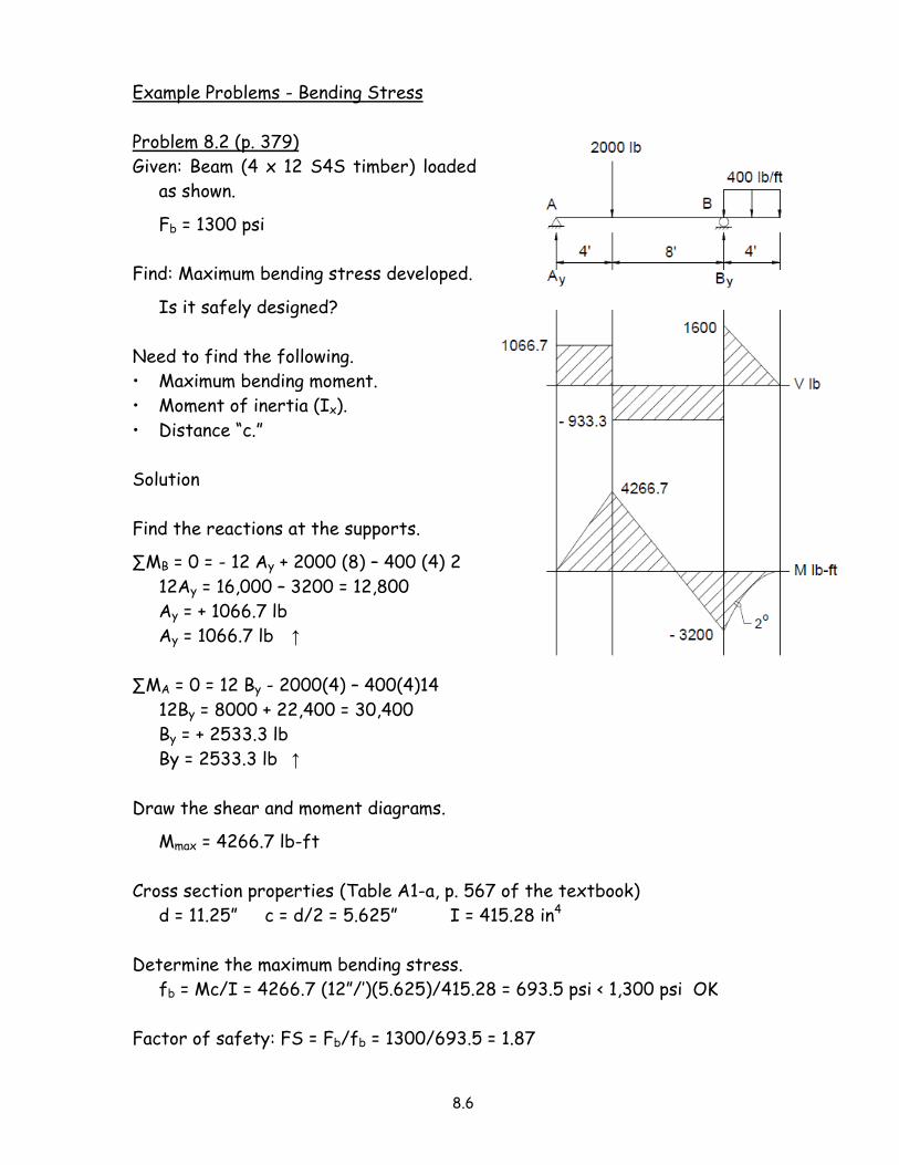
We can isolate a small, square element of this beam, and draw a free-body diagram
showing the stress acting on it.
• Assume Δx = Δy and that the
elemental square is very small.
8.12
• For equilibrium vertically, the
following must be true.
∑Fy = 0, thus fv1 = fv2
• In addition, the shear stresses fv1
and fv2 form a moment couple.
For the elemental square to be in
equilibrium, the moment equation must
also be satisfied.
∑MO = 0, thus fv2 (Δx) = fv3 (Δy)
• Since Δx = Δy
fv1 = fv2 = fv3 = fv4
• Shear stresses fv1 and fv2 form a
clockwise couple; fv3 and fv4 form a
counterclockwise couple.
From the preceding discussion we can conclude that at a given point along the beam
ftransverse = flongitudinal
8.4 Development of the General Shear Stress Equation
The general equation for shear stress is expressed mathematically as follows.
fv = VQ/Ixb
where
fv = shear stress (transverse or longitudinal)
V = shear in beam at a given point along the beam length (usually taken from the
shear diagram)
Q = Ay = first moment of area
A = area above or below the level at which the shear stress is being determined
8.13
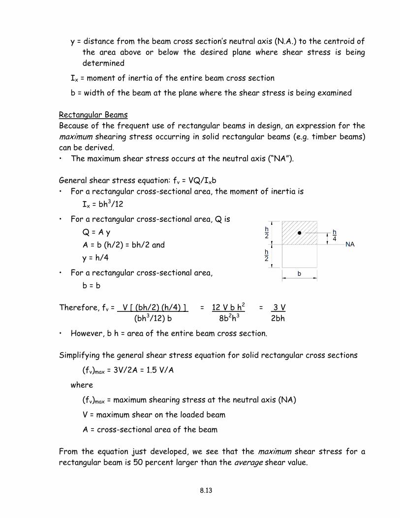
y = distance from the beam cross section’s neutral axis (N.A.) to the centroid of
the area above or below the desired plane where shear stress is being
determined
Ix = moment of inertia of the entire beam cross section
b = width of the beam at the plane where the shear stress is being examined
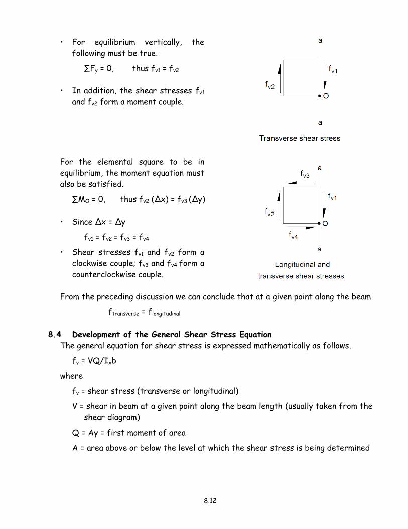
Rectangular Beams
Because of the frequent use of rectangular beams in design, an expression for the
maximum shearing stress occurring in solid rectangular beams (e.g. timber beams)
can be derived.
• The maximum shear stress occurs at the neutral axis (“NA”).
General shear stress equation: fv = VQ/Ixb
• For a rectangular cross-sectional area, the moment of inertia is
Ix = bh3/12
• For a rectangular cross-sectional area, Q is
Q = A y
A = b (h/2) = bh/2 and
y = h/4
• For a rectangular cross-sectional area,
b = b
Therefore, fv = V [ (bh/2) (h/4) ] = 12 V b h2 = 3 V
(bh3/12) b 8b2h3 2bh
• However, b h = area of the entire beam cross section.
Simplifying the general shear stress equation for solid rectangular cross sections
(fv)max = 3V/2A = 1.5 V/A
where
(fv)max = maximum shearing stress at the neutral axis (NA)
V = maximum shear on the loaded beam
A = cross-sectional area of the beam
From the equation just developed, we see that the maximum shear stress for a
rectangular beam is 50 percent larger than the average shear value.

8.14
Example Problems - Shear Stress
Problem 8.12 (p. 399)
Given: A log with a diameter D is used
as a 32’ beam and is loaded as
shown.
Fb = 1200 psi; Fv = 100 psi
Find: Diameter D.
From the V and M diagrams:
Vmax = 6400 lb; Mmax = 51,200 lb-ft
Ix = π D4/64
c = D/2
y = 4R/3π
Determine the required diameter D for flexure.
fb = Mc/Ix = 51,200 (12”/’) (D/2) = 307,200 D = 6.257 (106)
π D4/64 0.0491 D4 D3
Let fb = Fb: Fb = 1200 psi = 6.257 (106)
D3
D3 = 6.257 (106)/1200 = 5214.2 D = 17.34”
Determine the required diameter D for shear.
fv = VQ/Ixb
Q = ½ (π D2/4) (4r/3π) = (π D2/8) [4(D/2)/3π] = D3/12
b = D
fv = VQ/Ixb = (6400) (D3/12) = 533.3 D3 = 10,865
(π D4/64) D 0.0491 D5 D2
Let fv = Fv: Fv = 100 psi = 10,865/D2
D2 = 10,865/100 = 108.65 D = 10.42”
Flexure controls: Use 18” diameter log

8.15
Problem 8.13 (p. 399)
Given: Composite beam loaded as shown.
Fb = 22 ksi; Fv = 14.5 ksi
Find: a) Maximum load w
b) Shear stress fv between plate
and top flange
Draw the V and M diagrams.
Vmax = 10w, Mmax = 50 w
Cross section properties for the W8 x 31
steel wide-flange beam (ref. Table A3,
p. 572 of the textbook).
A = 9.13 in2, d = 8.00”, Ix = 110.0 in4,
tw = 0.285”, bf = 7.995”, tf = 0.435”
Find the location of the centroid (use base of W-shape as reference).
Part Area y i Ai y i
1 9.13 4.0 36.52
2 10.0 8.5 85.0
19.13 121.52
y = 121.52/19.13 = 6.352”
Compute the moment of inertia with respect to the neutral axis (NA).
Ix = Ibeam + Iplate
Ix = 110.0 + 9.13 (6.352 – 4.0)2 + 10.0(1.0)3/12 + 10.0 (8.5 – 6.352)2
Ix = 110.0 + 50.51 + 0.83 + 46.14
Ix = 207.48 in4
c = 6.352” to bottom fibers (tension)
c = 8.00” + 1.0” – 6.352”
= 2.648” to top fibers (compression)
Use c = 6.352”

8.16
Assume flexure controls.
• Solve for the maximum load “w” based on flexure first.
fb = Mc/Ix = 50 w (12”/’) (6.352) = 3811.2 w = 18.37 w
207.48 207.48
Let fb = Fb: Fb = 22 ksi = 18.37 w
w = 22.0/18.37 = 1.20 kip/ft
• Determine the maximum shear based on the computed value for “w”.
Vmax = 10 w = 10 (1.20) = 12.0 kips
Check the shear stress between the plate and the top flange of the beam.
• Pick the easier portion of the cross section in calculating Q = A y .
- Use the upper portion of the cross section (i.e. the 1” x 10” plate).
Applicable equation: fv = VQ/Ixb
A (area of 1” x 10” plate) = 1” x 10” = 10.0 in2
y (i.e. the distance from NA to the centroid of 1” x 10” plate)
= 8.5” – 6.352” = 2.148”
Q = A y = (10.0) (2.148) = 21.48 in3
b = bf = 7.995”
Note: The flange width (bf) is used for b since bf = 7.995” and is less than 10”
(plate width). The smaller width gives a larger value of shear stress.
• Compute the shear stress between the plate and the top flange of the beam.
fv = VQ/Ixb = 12.0 (21.48) = 0.155 ksi < Fb = 14.5 ksi OK
207.48 (7.995)
Since the computed shear stress (i.e. fb) is significantly less than the allowable
shear stress (i.e. Fb), the assumption that flexure controls is apparently validated.
• Technically, the maximum shear stress occurs at the neutral axis and not
between the plate and the top flange of the beam.
• If fv > Fb = 14.5 ksi, then shear would control and the value of “w” would need to
be determined on the basis of shear rather than flexure.
• The value 14.5 ksi would then be used to determine the maximum shear force
and the corresponding value of w.

8.17
Shearing Stress Variations in Beams
Shear stress varies on a cross section, as illustrated for the various beam types
shown below.
Except for a few exceptions, the maximum shearing stress occurs at the neutral
axis.
The dashed curve for the I-beam indicates what the stress variation would be if
the beam area had remained rectangular with a constant width b.
• This variation would be similar to that shown for the rectangular beam.
• The sudden increase in shear stress at the underside of the top flange is due to
the abrupt change in the width (from b to t) in the shear stress equation
fv = VQ/Ib
A similar change occurs at the flange-to-web transition of a T-beam.
• The curve between the flanges follows the usual pattern for a rectangular
beam.
Consider the distribution of shear stresses for a wide-flange section.
• Most of the shear is resisted by the web.
• Very little resistance is offered by the
flanges.
The opposite is true in the case for flexural
stresses in a wide-flange section.
• The flanges resist most of the bending
stresses.
• The web offers little resistance to
bending.

8.18
In a wide-flange section, the calculation of the exact maximum shear stress using
VQ/Ib can be difficult because of the presence of fillets (rounding) where the
flange joins the web.
• A high level of accuracy is even harder to achieve in channels or standard I-
shapes that have sloping flange surfaces.
• The American Institute of Steel Construction (AISC) recommends the use of
the following approximate formula to determine an “average” shear stress for
common steel shapes.
(fv)average = V/tw d
where
V = shear force
d = beam depth
tw = web thickness
tw d = the area of the web (extending the full depth of the cross section)
This formula gives the average unit shearing stress for the web over the full depth
of the beam (ignoring the contribution of shear resistance from the flange).
• Webs resist approximately 90 percent of the total shear for structural shapes.
• In contrast, flanges resist 90 percent of the bending stresses.
Depending on the particular steel shape, the average shear stress formula
(fv)average = V/tw d
can be as much as 20 percent in error in the non-conservative direction.
• This means when a shear stress computed from this equation gets within 20
percent of the maximum allowable shear stress, the actual maximum stress
(VQ/Ib) might be exceeding the allowable stress by a small amount.
• If the shear stress becomes significant, compared to the allowable shear
stress, then a more rigorous analysis should be performed.
Fortunately, this low level of accuracy is seldom a problem for the following two
reasons.
• Structural steels are very strong in shear.
• Most beams and girders in buildings, unlike those in some machines, have low
shearing stresses.

8.19
High shearing stresses may be present in short-span, heavily loaded beams, or if
large concentrated loads are applied adjacent to the support.
• In determining the size of a steel beam, flexural stresses or deflections will
usually govern.
When shearing stresses do become excessive, steel beams do not fail by ripping
along the neutral axis, as might occur in timber beams.
• Compression buckling of the relatively thin web occurs and is what is considered
a shear failure.
• The AISC has provided several design formulas for determining when extra
bearing area must be provided at concentrated loads or when web stiffeners
are needed to prevent such failures.
Web failure due to excessive shear in steel beams

8.20
8.5 Deflection in Beams
The design of a beam includes an analysis of the following effects.
• Stress due to bending moment.
• Stress due to shear force.
• Deformation (called deflection in beams), especially in long-span structures.
Deflection, a beam characteristic related to stiffness, represents a change in the
vertical position of the beam axis due to applied loads.
The design of a beam may be governed by its permissible deflection, particularly
for higher strength steel members and for wood members.
• Factors that influence the amount of deflection that results to a loaded beam
include the following.
- The magnitude of the load.
The greater the load, the greater is the deflection.
- The beam’s span.
The longer the span, the greater is the deflection.
- The moment of inertia of the beam cross-section.
The larger the moment of inertia, the smaller is the deflection.
- The beam’s modulus of elasticity.
The greater the beam’s material stiffness, the smaller is the deflection.
Generally, the allowable or permissible deflection is limited by the following.
• Building codes.
• Practical considerations, such as minimizing plaster cracking in ceiling surfaces
or reducing the springiness of a floor.
Deflection is always a concern in structures consisting of wooden elements.
• Wood as a structural material is less stiff (i.e. a lower E-value) than steel or
concrete.
• In some design situations, primarily longer spans, a wood member satisfying the
strength requirements will not satisfy deflection criteria.
Detrimental effects from large deflections can include the following.
• Nail popping in gypsum ceilings.
• Cracking of horizontal plaster surfaces.
• Visible sagging of ceiling and floors.

8.21
Steel beams, although stronger relative to wood, need to be checked for
deflection.
• Particular care must be given in long-span situations because of the likelihood of
objectionable sag or ponding of water.
Ponding is potentially one of the most dangerous conditions for flat roofs.
• Ponding occurs when a flat roof deflects enough to prevent normal water
runoff.
• Some water collects in the mid-span and, with the added weight of accumulated
water, the roof deflects a little more, allowing even more water to collect,
which in turn causes the roof to deflect more.
• This progressive cycle continues until structural damage or collapse occurs.
Building codes require that all roofs be designed with sufficient slope to ensure
drainage after long-term deflection, or that roofs be designed to support maximum
roof loads, including the possible effects of ponding.
The allowable deflection limits for beams are given as follows (ref. Table 8.1,
p. 403 of the textbook).
LL only DL + LL
Roof beams:
Industrial L/180 L/120
Commercial and Institutional
without plaster ceiling L/240 L/180
with plaster ceiling L/360 L/240
Floor beams:
Ordinary usage* L/360 L/240
* Ordinary usage is for floors intended for construction in which walking comfort
and the minimizing plaster cracking are primary considerations.
These limits are based on the American Institute of Timber Construction (AITC),
American Institute of Steel Construction (AISC), and Uniform Building Code (UBC)
standards.
There are a number of ways to determine beam deflections.
• Established formulas.
• The moment area method.
• Double integration method.
8.22
This section will deal exclusively with the use of established deflection formulas
found in standard handbooks such as the AISC steel manual and timber design
manuals.
The Elastic Curve – Radius of Curvature of a Beam
The calculation of beam deflections is based on a mathematical approach requiring
the solution of a second-order differential equation.
• The amount of the deflection depends on the loading and type of end supports
of the beam.
The result of such calculations is the following equation.
1/R = M/EI
where
R = radius of curvature
M = bending moment at section where R is desired
E = modulus of elasticity
I = moment of inertia of the beam cross section
Deflection Formulas
Many loading patterns and support conditions occur so frequently in construction
that reference manuals (e.g. AISC, AITC) and engineering handbooks provide
tables of the frequently used deflection formulas.
• A few of the more common cases are shown in Table 8.2 (pp. 406 - 407 of the
textbook).
• Often the required deflection values in a beam design situation can be
determined by these formulas.
• The actual loading situation may be a combination of the tabulated cases.
- In such design situations, it is sufficiently accurate to determine the
maximum deflection using two or more of the formulas (known as
superposition).
Computed actual deflections must be compared against the allowable deflections
permitted by building codes to assure that deflection limits are not exceeded.
Δactual ≤ Δallowable
8.23
Example Problems - Deflection in Beams
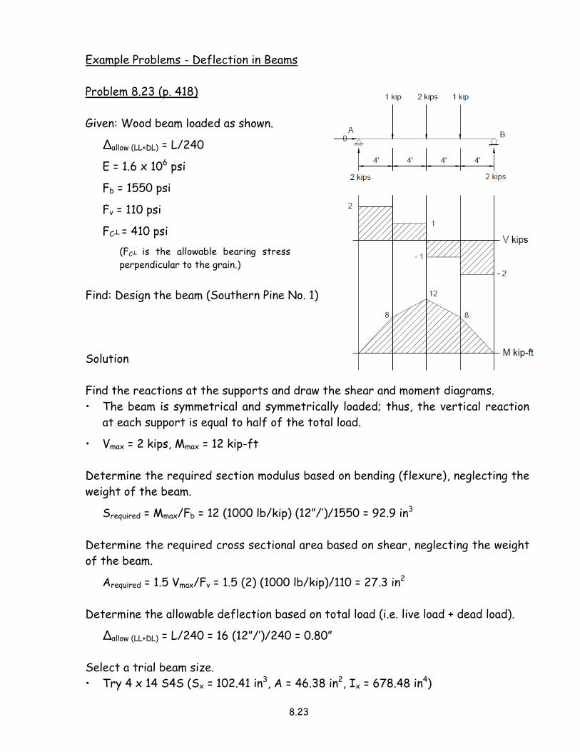
Problem 8.23 (p. 418)
Given: Wood beam loaded as shown.
Δallow (LL+DL) = L/240
E = 1.6 x 10⁶ psi
Fb = 1550 psi
Fv = 110 psi
FC┴ = 410 psi
(FC┴ is the allowable bearing stress
perpendicular to the grain.)
Find: Design the beam (Southern Pine No. 1)
Solution
Find the reactions at the supports and draw the shear and moment diagrams.
• The beam is symmetrical and symmetrically loaded; thus, the vertical reaction
at each support is equal to half of the total load.
• Vmax = 2 kips, Mmax = 12 kip-ft
Determine the required section modulus based on bending (flexure), neglecting the
weight of the beam.
Srequired = Mmax/Fb = 12 (1000 lb/kip) (12”/’)/1550 = 92.9 in3
Determine the required cross sectional area based on shear, neglecting the weight
of the beam.
Arequired = 1.5 Vmax/Fv = 1.5 (2) (1000 lb/kip)/110 = 27.3 in2
Determine the allowable deflection based on total load (i.e. live load + dead load).
Δallow (LL+DL) = L/240 = 16 (12”/’)/240 = 0.80”
Select a trial beam size.
• Try 4 x 14 S4S (Sx = 102.41 in3, A = 46.38 in2, Ix = 678.48 in4)
8.24
Check the effect of the beam’s weight (wbeam = 35 pcf = 0.252 lb/ft-in2):
• Determine the additional uniform load due to the weight of the beam.
wbeam = 0.252 lb/ft-in2 x cross section = (0.252) (46.38) = 11.69 lb/ft
• Determine the required section modulus based on bending (flexure), including
the weight of the beam, and check the actual bending stress.
Maddition = wbeamL2/8 = 11.69 (16)2/8 = 374.1 lb-ft
Saddition = Madd/Fb = 374.1 (12”/’)/1550 = 2.90 in3
Stotal = 92.9 + 2.90 = 95.8 in3 < 102.41 in3 OK
fb = Mmax/S = [12 (1000 lb/kip) + 374.1](12”/’)/102.41
= 1449.9 psi < Fb = 1550 psi OK
• Determine the required cross sectional area based on shear, including the
weight of the beam, and check the actual shear stress.
Vadd = wbeamL/2 = 11.69 (16)/2 = 93.5 lb
Aadd = 1.5 Vadd/Fv = 1.5 (93.5)/110 = 1.28 in2
Atotal = 27.3 + 1.28 = 28.6 in3 < 46.38 in2 OK
fv = 1.5 Vmax/A = 1.5 [(2) (1000 lb/kip) + 93.5]/46.38
= 67.7 psi < Fv = 110 psi OK
Determine the maximum deflection (i.e. the deflection at mid-span) for the simply
supported beam by combining Case (a), Case (b) and Case (d) from Table 8.2 (p. 406
of the textbook).
• Uniform load (due to the beam weight): Δactual = 5wL4/384EI
• Concentrated load at mid-span: Δactual = PL3/48EI
• Three equal concentrated loads at quarter points: Δactual = PL3/20.1EI
Δactual = 5 (11.69)(16)4(12”/’)3/384(1.6 x 106) (678.48)
+ 1 (1000)(16 x 12”/’)3/48(1.6 x 106) (678.48)
+ (1)(1000)(16 x 12”/’)3/20.1(1.6 x 106) (678.48)
= 0.016” + 0.136” + 0.324”
Δactual = 0.476” < Δallow (LL+DL) = 0.80” OK

8.25
Check bearing stress between 4 x 14 beam and 6 x 12 girder (used as the support).
fC┴ = P/Abearing
P = 2 (1000) + 11.69 (16)/2 = 2093.5 lb
Abearing = 3.5” (5.5”) = 19.25 in2
fC┴ = P/Abearing = 2093.5/19.25
= 108.8 psi < FC┴ = 410 psi OK
Select 4 x 14 S4S
8.26
8.6 Lateral Buckling in Beams
At the compression side of the beam, there is a tendency for the beam to buckle
(deflect sideways), just as a column can buckle under an axial load.
• When a simply supported beam is subjected to a load, the top flange or surface
is in compression.
• In a cantilever or overhang beam, the buckling or sidesway will develop due to
the compression on the bottom surface of the beam.
• Very narrow, deep beams are particularly susceptible to lateral buckling, even at
relatively low stress levels.
Beams need to be designed in such a way that the tendency of a beam to displace
laterally is resisted.
• The compression surface needs to be braced by other framing members.
• The beam needs to be re-proportioned to provide a larger Iy.
The vast majority of beams, such as floor and roof beams in buildings, are laterally
supported by the floor or roof structures attached to and supported by them.
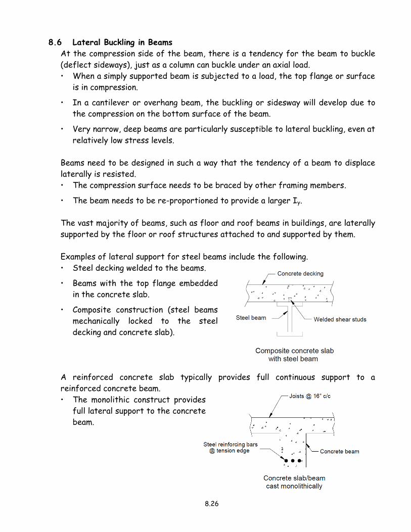
Examples of lateral support for steel beams include the following.
• Steel decking welded to the beams.
• Beams with the top flange embedded
in the concrete slab.
• Composite construction (steel beams
mechanically locked to the steel
decking and concrete slab).
A reinforced concrete slab typically provides full continuous support to a
reinforced concrete beam.
• The monolithic construct provides
full lateral support to the concrete
beam.

8.27
Wood framing typically employs continuous support along the top compression
surface.
• Sheathing nailed at a relatively close spacing and solid blocking provides
restraint against rotation at the ends.
Certain beams are inherently stable against any lateral buckling tendency by virtue
of their large cross-sectional shapes.
• A rectangular beam with a large width-to-depth ratio (Ix and Iy are relatively
close) and loaded in the vertical plane should have no lateral stability problem.
• A wide-flange beam having a compression flange that is both wide and thick to
provide a resistance to bending in a horizontal plane (relatively large Iy) will also
have considerable resistance to buckling.
The problem of lateral instability in unbraced steel beams (W shapes) is amplified
because the cross-sectional dimensions are such that relatively slender elements
(i.e. flange) are stressed in compression.
• Slender elements have large width-to-thickness ratios, and these elements are
particularly susceptible to buckling.
• A beam that is not laterally stiff in cross section must be braced every so
often along its compression side in order to develop its full moment capacity.
• Sections not adequately braced or laterally supported by secondary members
could fail prematurely.

8.28
The allowable stress is determined by the lateral support provided.
• The design of steel beams often assumes an allowable bending stress of
Fb = 0.6 Fy, where Fb = 21.6 ksi for A36 steel.
• Steel beams laterally supported along their compression flanges, meeting the
specific requirements of the AISC, are allowed to use an allowable Fb = 0.66 Fy,
where Fb = 23.8 ksi for A36 steel.
• When the unsupported lengths of the compression flanges become large, the
allowable bending stresses may be further reduced below the Fb = 0.6Fy level.
For the purposes of preliminary sizing of steel beams in architectural practice, the
allowable bending stress is often taken as Fb = 0.60 Fy (21.6 ksi for A36 steel, 33.0
ksi for high strength steel with Fy = 50 ksi).
In the case of timber beams, the dimensions of the cross sections are such that
the depth-to-width ratios are relatively small.
• Roof sheathing or flooring is often nailed to timber beams to provide virtually
continuous lateral support.
• A stability factor is used to determine the allowable stress in the design of
wood beams when beams are not fully supported.
Related Documents