Bandwidth Aggregation in Heterogeneous Networks
Kameswari Chebrolu, Ramesh RaoDepartment of ECE
University of California, San Diego
Introduction
• Recent mobile Internet growth spurred deployment of different wireless technologies– e.g. GPRS, CDMA2000, HDR, 802.11, Bluetooth, Iridium etc
• End-Users have flexibility regarding Interface choice– Can choose any number of interfaces to best fit application
needs
• Simultaneous use of multiple interfaces opens interesting possibilities– Bandwidth Aggregation, Mobility Support, Security, Reliability
• Problem Statement:– How to effectively aggregate bandwidth across multiple
network interfaces?

Motivation
• Applications will drive next-generation network deployments
• Video Applications• Video-on-demand• Interactive video• Video conferencing• Multiplayer games
– Bandwidth requirements: 250 Kbps to 2-3 Mbps– Problem:
• Wireless interfaces have bandwidth limitations• 50 Kbps – 384 Kbps (GPRS, CDMA2000)
• TCP applications can also benefit from bandwidth aggregation

Challenges in Bandwidth Aggregation
• Use of multiple interfaces Reordering• Video applications have stringent QoS
requirements– Interactive applications
• One way latency of 150ms , Max limit 400ms• Frame loss rate < 1%
– Video on Demand (with VCR functions):• One way latency of 1-2 sec• Frame loss rate < 1%
– Cannot tolerate excess delay due to reordering
• TCP applications– More than 3 duplicate acks invokes congestion
control – Bandwidth probing issues
• Inter arrival between acks does not reflect available bandwidth
Related Work
• Link-Layer Solutions– Bonding – aggregates circuit switched lines– IMA – ATM technology for aggregating multiple point-to-
point links– Multilink PPP
• Stripe Protocol – Generic load-sharing protocol based on Surplus Round
Robin (SRR)– Minimizes packet processing overhead– SRR similar to WRR
• Accounts for variable sized packets• Surplus (unused bandwidth) is carried on to next round
Related Work (Contd.)
• Transport-Layer Solutions– RMTP
• Reliable rate-based transport protocol• Flow and congestion control based on bandwidth
estimation
– Parallel TCP (pTCP)• Opens multiple TCP connections on each interface • Handles congestion and blackout through data
reallocation and redundant striping
• Network-Layer Solutions– Based on tunneling– Weighted round-robin based scheduling
Outline
• Architecture• Scheduling algorithm• Evaluation
– Analysis– Trace-based simulation
• Ongoing work
Outline
• Architecture• Scheduling algorithm• Evaluation
– Analysis– Trace-based simulation
• Ongoing work

Architecture for Bandwidth Aggregation
• Link-Layer Solutions infeasible– End point is an IP address
• Application/Transport Layer Solutions– Need to modify/rewrite code– Ensure compatibility with existing infrastructure
• Network Layer solution – IP – a single standard– Application transparency and interoperability– Cleanest Solution
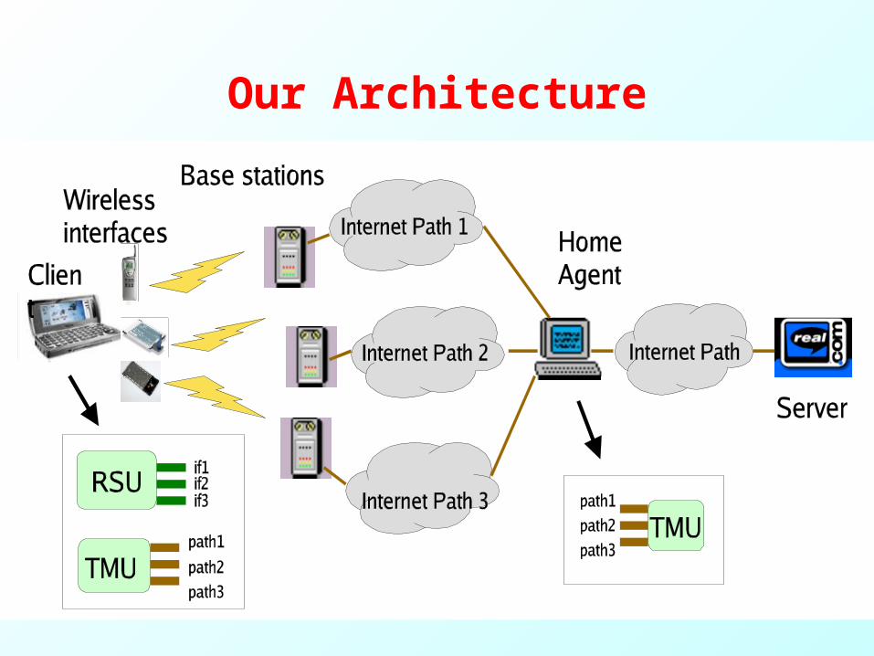
Our Architecture

Architecture Details• Mobile IP based
– Packets pass through Home Agent (HA)– Simultaneous Binding - multiple Care-of-Address registration– Intelligent scheduling of packets to multiple addresses
• Radio Access Network Selection Unit (RSU)– Located on Mobile Host (MH)– Selects right interfaces based on app. reqmts. and cost– Update bindings with HA
• Traffic Management Unit (TMU)– Located on HA and MH – Processes and schedules the incoming traffic onto multiple
paths– Conveys application type and end goal requirements to HA
• Scheduling Algorithm in TMU is crucial– Focus on Interactive Real-Time Applications
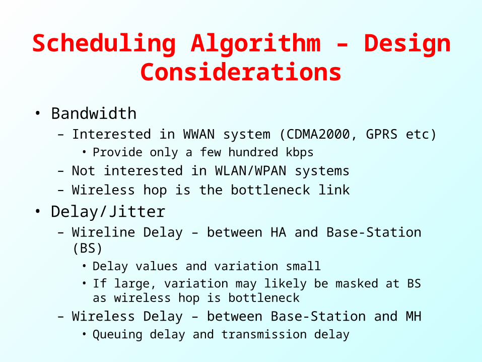
Scheduling Algorithm – Design Considerations
• Bandwidth– Interested in WWAN system (CDMA2000, GPRS etc)
• Provide only a few hundred kbps
– Not interested in WLAN/WPAN systems– Wireless hop is the bottleneck link
• Delay/Jitter– Wireline Delay – between HA and Base-Station (BS)
• Delay values and variation small• If large, variation may likely be masked at BS as wireless
hop is bottleneck
– Wireless Delay – between Base-Station and MH• Queuing delay and transmission delay
Scheduling Algorithm – Design Considerations
• Qos Support– Interested in systems that provide QoS (CDMA2000,
UMTS etc not HDR)– Negotiated bandwidth and loss rate guaranteed for
duration of session
Design Possibility – Weighted Round Robin
• Schedules packets based on bandwidths of interfaces
• Not suitable for real-time applications• Example:
• Three interfaces with bandwidth ratios 5:2:1• Packets 1-5 sent on IF1, 6-7 sent on IF2, 8 on IF3• Packet 6 arrives ahead of packets 3,4,5• Packet 3 suffers excess delay due to reordering• Ideal ordering: IF1 – 1,2,4,5,6; IF2 – 3,7; IF3 – 8
• Variants of WRR – Surplus Round Robin (SRR), Shortest Queue First face similar problems

Our approach:Earliest Delivery First
• For each path (between HA and MH), estimate arrival time of a packet at MH
• Estimation based on– Bandwidth of the interface– One-way wireline delay (estimated) on the Internet path
• Schedule the packet on the path that delivers the packet the earliest
• Quick remarks– No need for synchronized clocks (relative one-way delay
counts)– EDF is not work conserving– EDF cannot totally eliminate reordering– Multiple applications can be handled by combining EDF with
Weighted Fair Queuing (WFQ)

EDF Details• Each path l is associated with three quantities
– A variable , which is the time the channel becomes available next.
– , the one-way wireline delay (estimate) of the path – , the bandwidth negotiated
• - the arrival time, - the size of packet i, • Packet i scheduled on path l would be delivered at the MH
at
• EDF schedules the packet on the path p for which
• is updated to
lA
lD
ia iL
lillili BLADad /),max(
}1,:{ Nmddlp mi
li
pid
lB
pA
Performance of EDF
• How well can EDF perform?– Can the application QoS requirements be met?– Is performance as good as having a Single-Link (SL) with
the same aggregated bandwidth?
• Approach– Analysis
• Prove fairness of EDF in distributing bits across different links• Compare EDF with SL in terms of work, delay, jitter and
buffering
– Simulation• Consider application performance level metrics • Measure sensitivity of the algorithm to bandwidth
asymmetry, number of interfaces, delay variation, channel losses

Properties of EDF• Notation:
– - max packet Size, – number of interfaces, - bandwidth of link l, - weight of link l (normalized bandwidth)
• Assumptions:– , and
• When packets are of constant size, they arrive in order at the client
• For variable sized packets – Given P packets to transmit, the maximum difference in normalized bits allocated to any two pair of links is – For WRR, this amount is a function of P and can be unbounded– For SRR it is
maxL
maxL lB
lwN
01 a 0lA0lD
max2L
max2L

Properties of EDF (Contd.)• For any time t, the difference between the total number of
bits W serviced by SL and EDF is
• The difference in delay experienced by a packet i in SL and EDF is bounded by
• The jitter experienced by a packet i without buffering is upper bounded by
• The jitter experienced by a packet I with buffering is upper bounded by
• The buffer size needed to deliver the packets in order is
N
ll
iN
ll
N
ll
SLi
EDFi
B
LN
B
wLdd
11
1max )1(
)1(
min/ BLi
max/ BLimax)1( LN
)1(),0(),0(1
max
N
llEDFSL wLtWtW

Experimental Methodology
• Trace driven simulation• Server
– Video frame traces – office cam (Mpeg4 and H.263)• For MPEG-4, avg – 400kbps, peak - 2Mbps, frame period - 40ms• For H.263, avg – 260kbps, peak – 1.5Mbps, frame period -
variable• Maximum packet size assumed is 1400 byte
• Home Agent– Employs scheduling algorithm
• Base-Station– No cross traffic– Serve packets first-come-first-serve basis

Experimental Methodology (Contd.)
• Client– Begin video display after a fixed delay – startup latency L– Afterwards, display frames consecutively every t seconds
(frame period)– Arrival after playback deadline results in frame loss– Startup latency bounds one-way delay of packets
• Internet Path– Packet delay traces collected over different Internet paths – Hosts on UCSD, UCB, Duke, CMU – Wireline delay range used 15ms – 22 ms (one-way)
• Algorithms under comparison– Single Link – SL– Surplus Round Robin - SRR

Application Performance Metrics
• Backlog in the system• Delay experienced by packets• Frame Loss probability - Fraction of packets
that miss playback deadline• Glitch Duration: Number of consecutive frames
that cannot be displayed• Glitch Rate: Number of glitches/sec

Bandwidth Allocation
% Bandwidth Needed over SL to achieve 0% frame loss, MPEG-4, BS = 3

Backlog
SL EDF SRR
Backlog in the system between HA and Client application, MPEG-4
• Bandwidth fixed at 600kbps
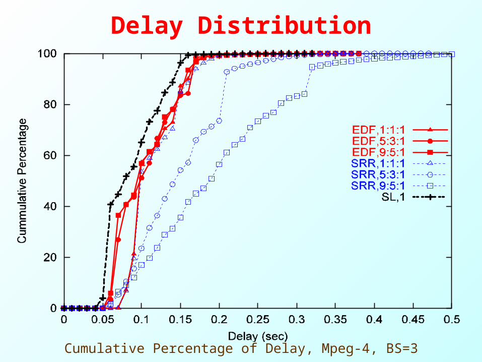
Delay Distribution
Cumulative Percentage of Delay, Mpeg-4, BS=3

Frame Loss probability
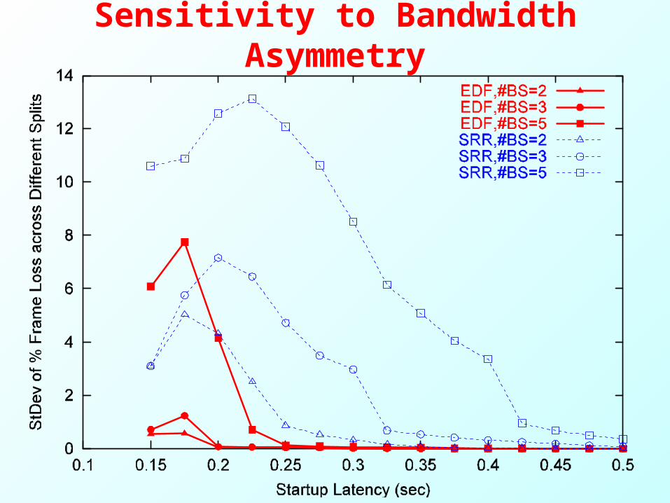
Sensitivity to Bandwidth Asymmetry

Sensitivity to Number of Interfaces

Extensions to EDF

Other Results• Delay Variation : EDF
– Truncated Gaussian with mean 22ms, std. devn. 0-10ms– For a split 5:3:1 at 225ms,
• No variation introduces 0.26% frame loss• 5ms variation, 0.27% frame loss• 10ms variation, 0.28% frame loss
• Channel Losses– Limited retransmissions help
• Other Applications– Non-Interactive Applications
• Large tolerance for delay no big difference in relative perf.
– Video-On-Demand Applications• High peak-to-mean rates imply over-provisioning of bandwidth
– Choice of scheduling algorithm does not matter
Summary
• Network-layer architecture to enable multiple communication paths
• EDF scheduling algorithm: reduces delay experienced by packets in presence of multi-path.
• An analysis of the algorithm shows that it doesn’t differ much from idealized SL
• Trace-driven simulations– EDF mimics SL closely– Outperforms by a large margin WRR based approaches

Ongoing Work
• Bandwidth Aggregation in Best-Effort Systems– Bandwidth Estimation at MH– Work ahead scheduling
• TCP– Support TCP applications – Network layer solutions
• Ad-hoc Networks• Security