AREVA T&DPower Electronics – HVDC & FACTSPower Electronics HVDC & FACTS
Jourden SergeSenior Area Manager Europe/Africa/China
The 2 nd of March 2007
2 2

AREVA Group Overview
AREVA T&D Overview
AREVA T&D Businesses
AREVA T&D OfferingAREVA T&D Offering
3 3
Organization of the group
FRONT ENDDivision
REACTORS & SERVICESDivision
BACK ENDDivision
TRANSMISSION& DISTRIBUTION
Division
• Plants
• Equipment
• Mining
• Chemistry
• Treatment
• Recycling• Products
• ServicesEquipment
• Nuclear Services
• Nuclear Measurements
• Consulting& Information Systems
Chemistry
• Enrichment
• Fuel
Recycling
• Logistics
• Clean-up
• Engineering
• Services
• Systems
• Automation
4 4
• AREVA TA
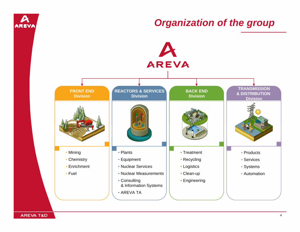
AREVA around the globe
100 countriesMarketing & Sales
€6,754M: 67%of all sales come from outside France
40 countriesProduction & Manufacturing
EUROPE & CIS63% of sales- Nuclear: 77%- T&D: 23%43,279employees
ASIA-PACIFIC12% of sales- Nuclear: 45%
NORTH & SOUTHAMERICA18% Nuclear: 45%
- T&D: 55%5,824employees
18% of sales- Nuclear: 74%- T&D: 26%7,912employees AFRICA &
MIDDLE EAST7% of sales7% of sales- Nuclear: 12%- T&D: 88%1,745employees
5 5
Production & manufacturing

AREVA Group Overview
AREVA T&D Overview
AREVA T&D Businesses
AREVA T&D OfferingAREVA T&D Offering
6 6

T&D Division
Complete range of products, systems and servicesfor electricity transmission and distribution:
Regulation
Transformation
Dispatching of electric current in power grids
~€4 000M€4,000MSales in 2006
~22,000Employees
7 7

Our Businesses
PRODUCTS SYSTEMS AUTOMATION SERVICE
• Turnkey Transmission Projects• Turnkey Distribution
Projects
• HV Switchgear• Power and
Distribution Transformers
• Automation Products• Automation Systems• Automation Support
• Network Consulting• Erection &
Commissioning• Maintenance &
• Power Electronics• Decentralized Power
Supply Systems
• Measurement Transformers• MV Switchgear
Repair & Retrofit• Spare Parts• Training and
Expertise• Proximity Projects • Total Asset Care
8 8
• Total Asset Care

AREVA Group Overview
AREVA T&D Overview
AREVA T&D Businesses
AREVA T&D Offering
AREVA T&D Power Electronics– HVDC & FACTSHVDC & FACTS
9 9
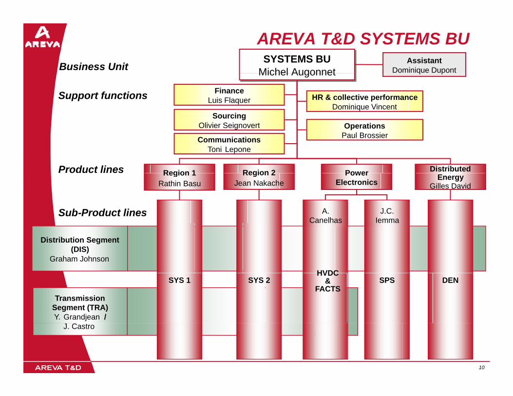
AREVA T&D SYSTEMS BUBusiness Unit Assistant
Dominique DupontSYSTEMS BU
Michel AugonnetSYSTEMS BU
Michel Augonnet
Support functions
O ti
FinanceLuis Flaquer
SourcingOli i S i t
q p
HR & collective performanceDominique Vincent
Michel AugonnetMichel Augonnet
OperationsPaul Brossier
Olivier Seignovert
Region 1 Region 2Product lines DistributedPower
CommunicationsToni Lepone
Region 1Rathin Basu
Region 2Jean Nakache
EnergyGilles David
Sub-Product lines
Power Electronics
A. Canelhas
J.C. Iemma
Distribution Segment (DIS)
Graham Johnson
HVDC
Transmission Segment (TRA)Y. Grandjean /
SYS 1 DENSYS 2HVDC
& FACTS
SPS
10 10
J. Castro
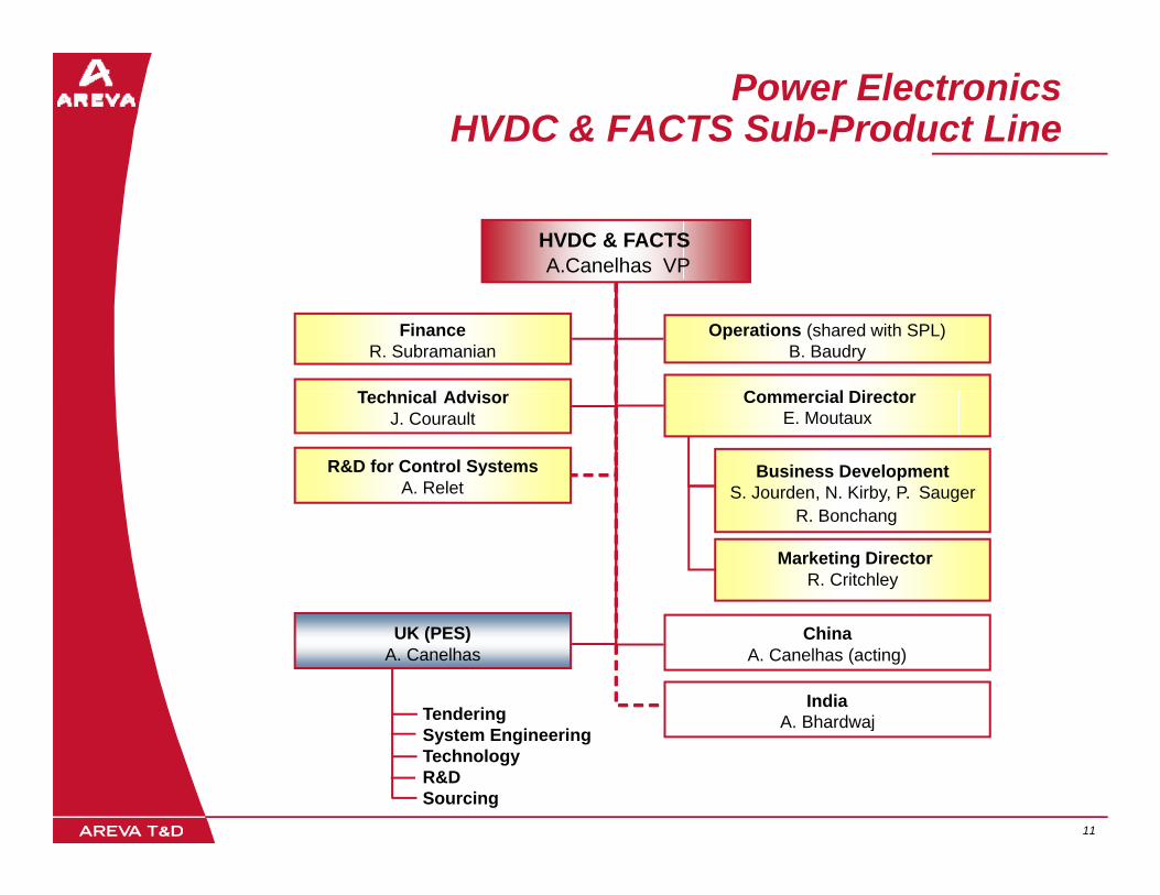
Power ElectronicsHVDC & FACTS Sub-Product Line
HVDC & FACTSA. Canelhas VP
Operations (shared with SPL)B. Baudry
FinanceR. Subramanian
C i l Di tT h i l Ad i Commercial DirectorE. Moutaux
Technical AdvisorJ. Courault
R&D for Control SystemsA. Relet
Business DevelopmentS. Jourden, N. Kirby, P. Sauger
Marketing DirectorR. Critchley
R. Bonchang
UK (PES)A. Canelhas
ChinaA. Canelhas (acting)
IndiaA. BhardwajTendering
S t E i i
11 11
jSystem EngineeringTechnologyR&DSourcing

HVDC & FACTSS b P d t Li
Power ElectronicsScope of Activities
Sub-Product Line
Power Flow Control500
kV
HVDC: for both Back to Back and Point to Point schemes (overhead line or cable)
Power QualityHVDC
FACTS: SVC, STATCOM….. for Utilities and Industry
Power SuppliesElectrolysis substation: for production of aluminium
HVDC
Electrolysis substation: for production of aluminium, chlorine, copper, zinc up to 500kA -1500VDC.Traction substation: for both AC and DC suppliesSpecial supplies, e.g. laboratories
38FACTS p pp , g
ELECTROLYSIS1.5
kA
15
TRACTION
0
12 12
6 5004kA
200

Power Electronic Activities Interacting Key Domains
System Studies/Design
Power transformerMachine
MICROELECTRONIC POWERC O C O CCOMPONENTS COMPONENTS
POWER
INTEGRATION
ALGORITHMS TOPOLOGY
R b t INTEGRATION
COOLINGRobustness
AREVA T&D PEA
13 13
AREVA T&D PEA

Basic HVDC Transmission
DC link ReceivingSendingE d
InverterRectifier
TransformerEndEnd
Vdc
F FIdc
Harmonic Filter(Reactive Power)
Idcii i
t
Idci
t
i
Iact
i
Iac
14 14

Basic HVDC TransmissionBack to Back
InverterRectifier ReceivingSendingE d
TransformerEndEnd
Vdc
F F
Idc
Harmonic Filter(Reactive Power)
Idcii i
t
Idci
t
i
Iact
i
Iac
15 15
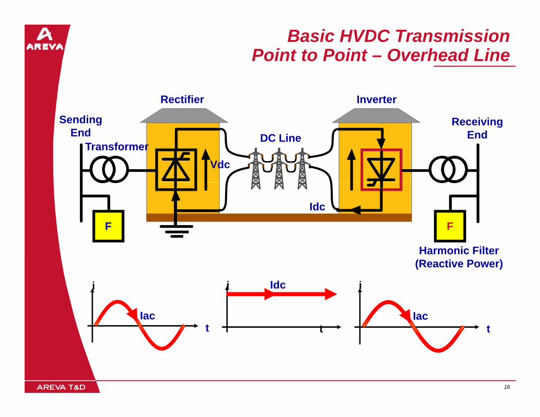
Basic HVDC TransmissionPoint to Point – Overhead Line
InverterRectifier
ReceivingSendingE d DC Line
TransformerEndEnd
Vdc
F F
Idc
Harmonic Filter(Reactive Power)
Idcii i
t
Idci
t
i
Iact
i
Iac
16 16

Basic HVDC TransmissionPoint to Point – Submarine Cable
InverterRectifier
ReceivingSendingE d
TransformerEndEnd
Vdc
F F
Idc
Harmonic Filter(Reactive Power)
Idcii i
t
Idci
t
i
Iact
i
Iac
17 17

Basic HVDC TransmissionPoint to Point – Underground Cable
InverterRectifier
ReceivingSendingE d
TransformerEndEnd
Vdc
F F
Idc
Harmonic Filter(Reactive Power)
Idcii i
t
Idci
t
i
Iact
i
Iac
18 18

HVDC Configuration OptionsMonopole & Bipole
Monopole example at 500 MW500 MW Monopole
FF F FFF F FPole 1
500 MWPole 1
500 MWAC
HV Cable
LV Cable AC
+ +
Bipole example built from two 500 MW poles
FF F FFF F F
1000 MW Bipole
HV Cable+ +FF F FFF F F
FF F FFF F F
Pole 1500 MW
Pole 1500 MW
LV CableAC AC
19 19
Pole 2500 MW
Pole 2500 MW
HV Cable- -

Classical 12-pulse HVDC SchemeMain Equipment
Converter Transformers
DC ReactancesThyristor Bridges
DC Filters
~ ~+
Vdc
FF FF DC lineSwitched Filter
BanksSwitched Filter
Banks
FF FF
_
Banks Banks
Many thyristors connected in series3-phase, 6-pulse
20 20
in series3 phase, 6 pulse bridge
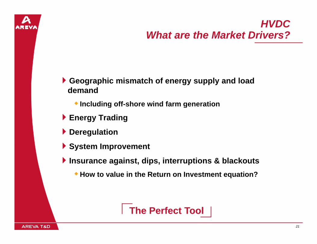
HVDCWhat are the Market Drivers?
Geographic mismatch of energy supply and load demand
Including off-shore wind farm generationg g
Energy Trading
Deregulation
System Improvement
Insurance against, dips, interruptions & blackoutsHow to value in the Return on Investment equation?
21 21
The Perfect Tool
Advantages of HVDC Links
The Power Flow on an HVDC link is Fully Controllable - Fast and Accurate!
The Operator or automatic controller determines how much power flowsThe Operator or automatic controller determines how much power flows via the link
An HVDC Link is asynchronous - the ac voltage and frequency in the two ac networks can be controlled independently of each other.
The HVDC link can be used to assist one (or even both) of the ac networks (e.g. power system damping)
HVDC links do not increase the Short Circuit Level of the system
Faults don’t transfer across HVDC interconnected systems
HVDC provides increased Transmission Capacity in a fixed corridor“Up to 3 times more power per tower”Up to 3 times more power per tower
HVDC can transport energy economically and efficiently over longer distance than ac lines or cables.
22 22
Sometimes HVDC is the only option!

Why Use HVDC?
C ti f t tiConnection of remote generation >700km
Submarine links
StationCost
>40km
Frequency conversion 50 60Hz
DCConvertorS i
DCBreak EvenDistance
50-60Hz
When synchronism of AC connections is impossible
Stations
ACStations
AC
Stations
TransmissionDistance
23 23
The Perfect Tool

AREVA - Pioneers in HVDC
Inventors of Phase Locked Loop (1960s - now Industry standard)
Operation at less than unity short-circuit power ratio
)
3-terminal HVDC scheme
AC system damping control
Water/Glycol single circuit cooling system
Unmanned HVDC scheme 4-terminal HVDC scheme
Largest capacity (2000MW) submarine cable scheme with
“Black-start” capability at receiving end
I t t t lsubmarine cable scheme, with highest utilisation of all such schemes
No smoothing reactor required
Inverter current control
Operation without telecommunications
No smoothing reactor required
Four-winding converter transformers
Creating a national grid using back-to-back HVDC
24 24

Our HVDC Experience
Nelson River OHL Konti-Skan 1De-icer+SVCDü h *
Cheju Haenam
Nelson River OHLBP1 1000MW 1973/93BP2 2000 MW 1978/85 *
380MW Cable2006
250MW2006
Dürnrohr *380MW B-B1983/97
Cheju-Haenam300MW Cable1999McNeill
150MW B-B UK-France
SACOI380MW Cable +OHL1967/85/93
1989Chandrapur2 x500MW B-B1997
2000MW Cable1986
GCCIA BtB
1967/85/93
Rivera
Vizag500MW B-B1999
Sasaram500MW B-B2001
GCCIA BtB3 x 600MW2008
Rivera 70MW B-B2000
Cahora Bassa *1920MW OHL1978
* AREVA T&D partnering with the German HVDC Group
25 25
~20% Market Share of HVDC Projects
AREVA T&DAREVA T&DSome Examples of our HVDC Experience
26 26

400kV400kV
F
F FSVC
F
F
F
F
F
F
F
F
F
F
F
F
F
SVC
Sellindge(NGC) La Manche
LesMandarins
(EDF)
SVC
27 27
Single line diagram IFA 2000
T1201

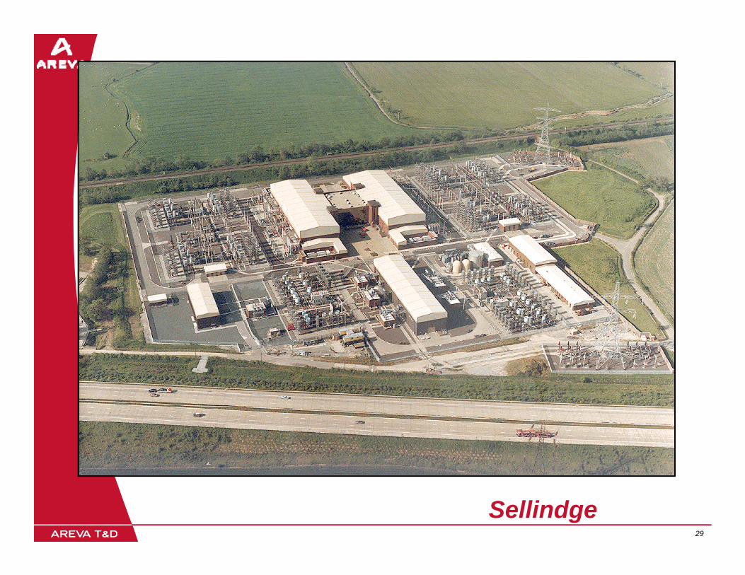
Cross ChannelSellindge Converter Station
2000MW double bipole HVDC scheme
In service 1985/86, Air cooled valves
SVC per bipole
World’s largest HVDC cable scheme
A il bilit
Bipole 2 Control Building
Bipole 1
AvailabilitySpecified = 95 %
Achieved > 97 5 %
Filters
Filters
BuildingAchieved > 97.5 %
Highest Utilization of
all HVDC Schemes Filters
99.5%EdF stated that the
scheme paid for itself 4
28 28
400kV GISSubstation
SVC 2 SVC 1Cable Route
scheme paid for itself 4 times over in the first 10 years of operation!
29 29
Sellindge
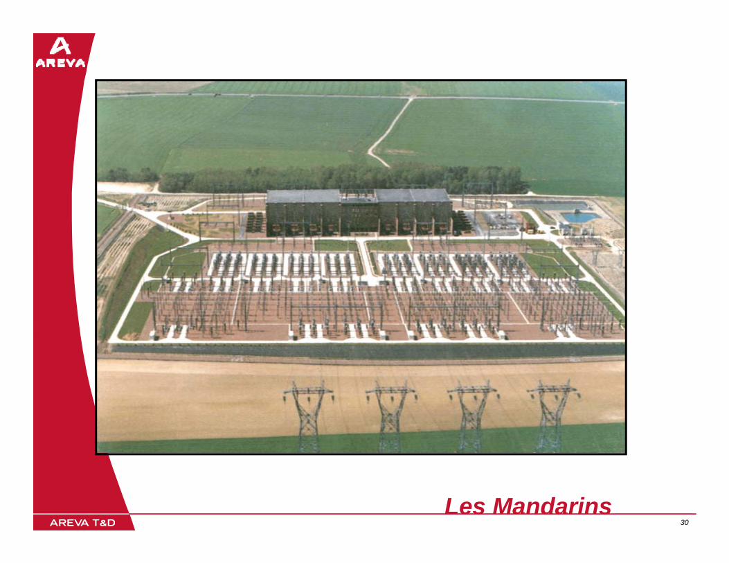
30 30Les Mandarins

Sardinia – Corsica – ItalySACOI
200 MW 200 kV Monopole
Overhead Line plus S b i C blSubmarine Cable
Commissioned 1967
Corsica tap added in 1986Corsica tap added in 1986
Italy
Corsica
Sardinia
31 31

South Korea - Cheju Cable Link
300 MW, ±180 kV, 840 A
100k b i bl li k100km submarine cable link
Commissioned 1997
Sole power source to load
Seoul
S. KOREASole power source to load-growth island
First HVDC link with:Inverter control of current
Operation without telecoms
“Bl k t t” t i i d“Black-start” at receiving endCheju
32 32

ALSTOM HVDC in India -Creating a National Grid
Sasaram 500 MW2002
ChandrapurChandrapur2 x 500 MW
1997Visakhapatnam 500 MW
1998
2 000 C S O
33 33
2,000 MW HVDC supplied by ALSTOM
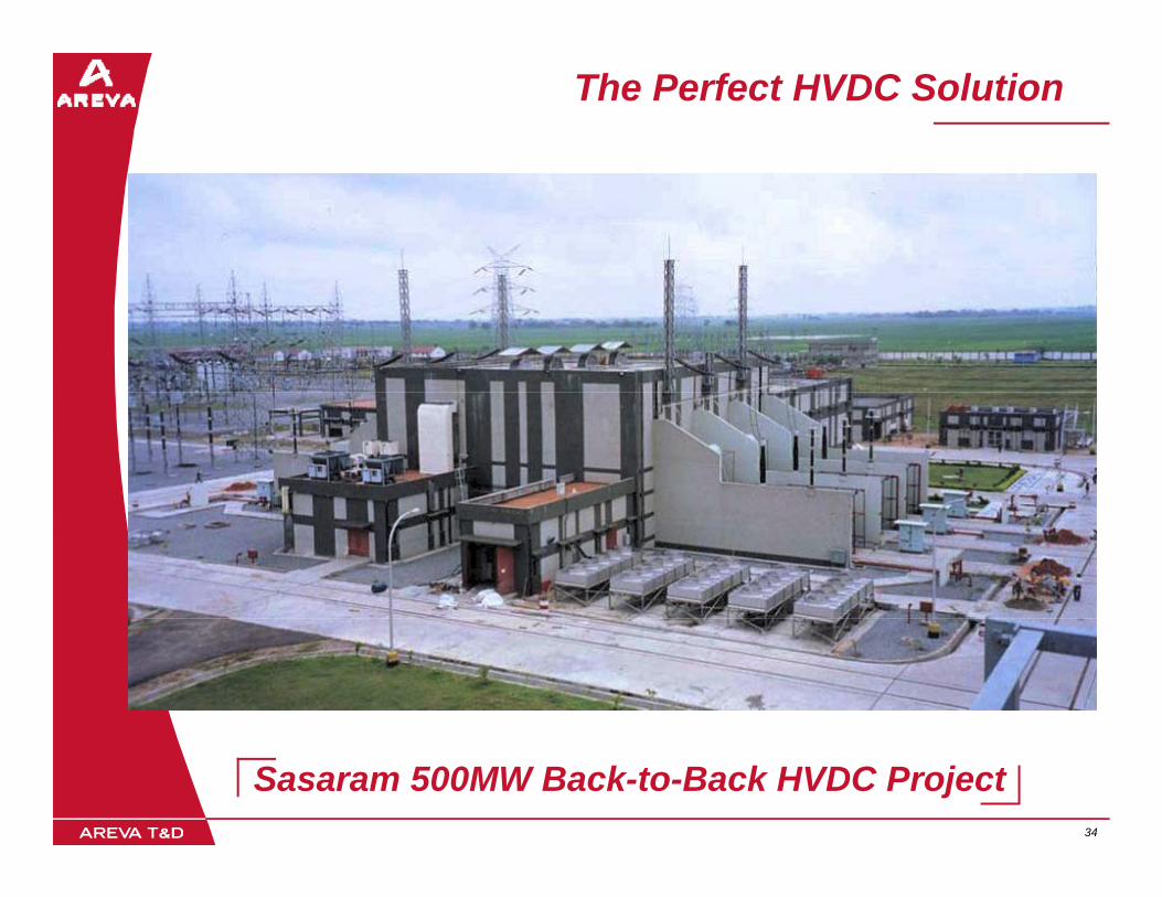
The Perfect HVDC Solution
34 34
Sasaram 500MW Back-to-Back HVDC Project

Recent experiences
2006: Successful commissioning of the HVDC link between Denmark and Swedenbetween Denmark and Sweden
2005: Order booked in Canada for an HVDCiceTM2005: Order booked in Canada for an HVDCiceHVDC that can be reconfigured as an SVC
2005: Order booked in Saudi Arabia for a 3*660 MW HVDC schemes for Gulf countries networks interconnection: GCCIA projectp j
35 35

HVDC link between Denmark and Sweden
Replace Pole 1 of HVDC submarineReplace Pole 1 of HVDC submarine link: Denmark to SwedenTwo new converter stations
Danish same site as Pole 2
KS2
KS1
Danish same site as Pole 2Swedish move to be at same site as Pole 2
Additi f bi l t l tAddition of a bi-pole control systemEnables high-level control of the existing Pole 2 as well as the new Konti-Skan 1 polepAutomatic balancing currents to cancel current flow in the sea
Converter stations fully automatedControl to be from a dispatch centre in Stockholm
Power increase to full cable rating
36 36
From 275MW to 380MWFrom 250kV to 285kV

Hydro-Quebec’s problem
During the ice storm in the winter of 1998, an accumulation of ice toppled towers andof ice toppled towers and downed hundreds of kilometres of high-voltage transmission lines.The ice storm generated ice buildup as much as 75mmAround 1 4 million people inAround 1.4 million people in Québec were without power for up to a week
37 37
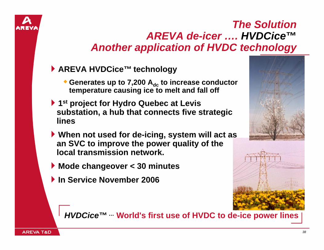
The SolutionAREVA de-icer …. HVDCice™
Another application of HVDC technologyAnother application of HVDC technology
AREVA HVDCice™ technologyGenerates up to 7,200 Adc to increase conductor temperature causing ice to melt and fall off
1st project for Hydro Quebec at Levis b t ti h b th t t fi t t isubstation, a hub that connects five strategic
lines When not used for de-icing, system will act as
SVC t i th lit f than SVC to improve the power quality of the local transmission network.Mode changeover < 30 minutesIn Service November 2006
38 38
HVDCice™ … World's first use of HVDC to de-ice power lines
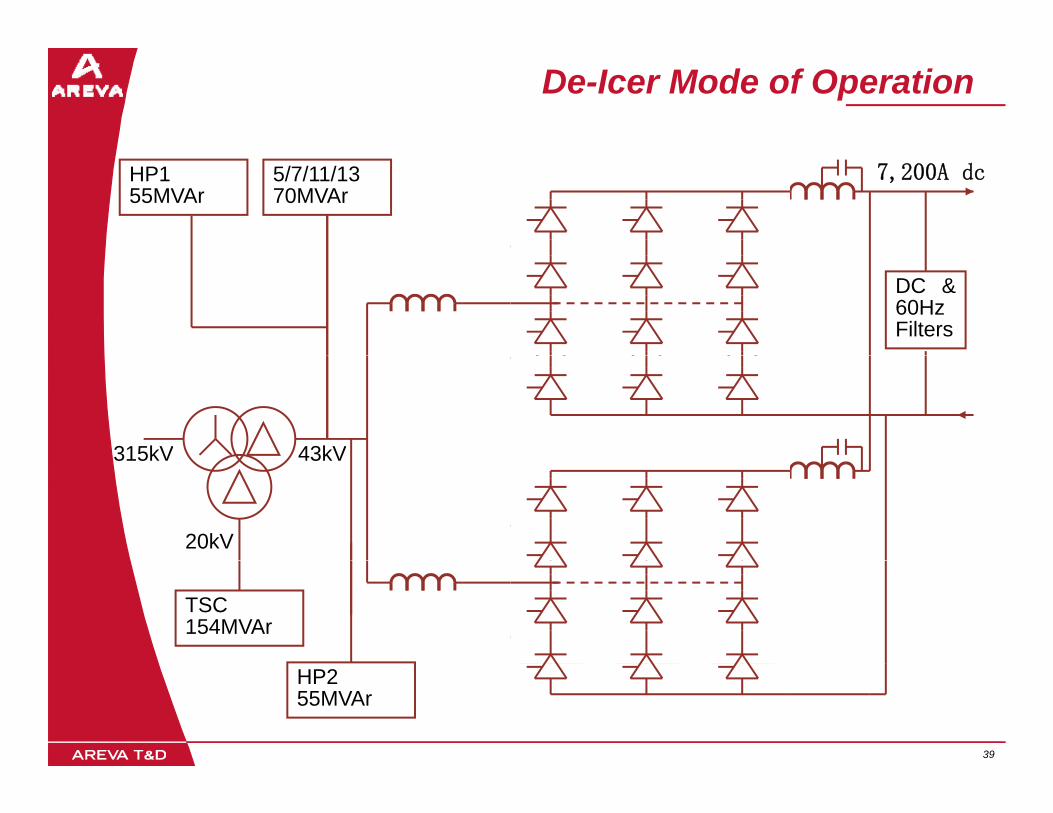
De-Icer Mode of Operation
5/7/11/1370MVAr
HP155MVAr
7,200A dc
DC &60HzFilters
315kV 43kV315kV 43kV
20kV
TSC154MVAr
39 39
HP255MVAr

…. To SVC Mode of Operation
5/7/11/1370MVAr
HP155MVAr
315kV TCR43kV
20kV
315kV TCR43kV
TSC154MVAr
40 40
HP255MVAr

GCCIA:Gulf countries networks interconnection
41 41

GCCIA : first HVDC in Gulf countries
Turnkey contract for three 600 MW
i lnominal power back-to-back HVDC schemes
616MW to be616MW to be installed per scheme to compensate f t lfor tolerances and transmission losses
Contract signed in Nov 2005
Commissioning by
42 42
Commissioning by end 2008.
GCCIA: Site Location

GCCIA: Scope of Works
3 HVDC Back to Back schemes will connect the 50Hz 400kV
Turnkey Solution
(Saudi Arabia) and 60Hz 380 kV ac gridsEach Back to Back rated at 600MW & located at the same site
But independent in operationBut independent in operation
Each converter station will consist of:AC switchyards with harmonic filter baysAC switchyards with harmonic filter baysConverter transformersThyristor valves and controlsCivil WorksCable connection to existing & New Substations
Onerous cooling requirements as ambient is +550C
43 43
Onerous cooling requirements as ambient is 55 CStringent limitations in use of water prevents use of evaporative cooling techniques
HVDC Valves
44 44
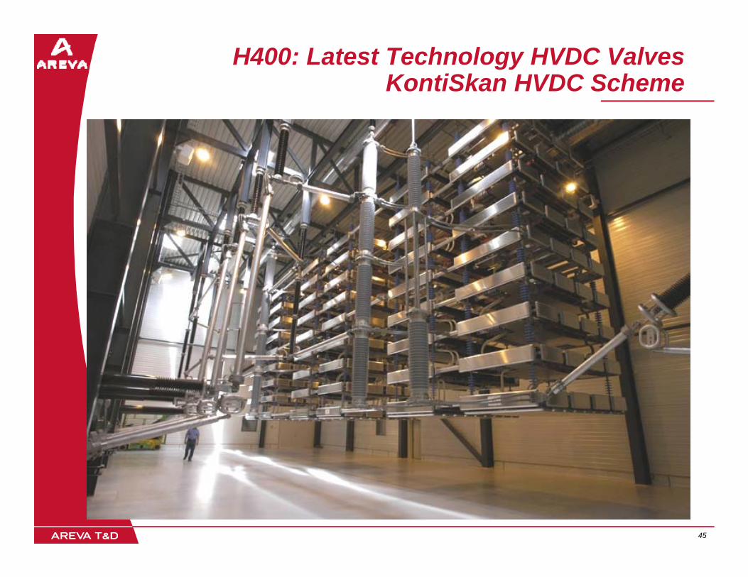
H400: Latest Technology HVDC ValvesKontiSkan HVDC Scheme
45 45

Latest TechnologyH400 HVDC Valves
Uses considerably fewer, state-of-the-art thyristor devices
Future-proofed for devices known to be made available during p gnext 10 yearsModular using a standardised approachapproach
Significant increase in reliability
Greater power per valve moduleGreater power per valve moduleReduces building sizes
>40% reduction in cost compared to previous version
Classified as world-beating by TransEnergie of Canada
46 46
TransEnergie of CanadaWorld’s most advanced HVDC user
Control Systems
47 47
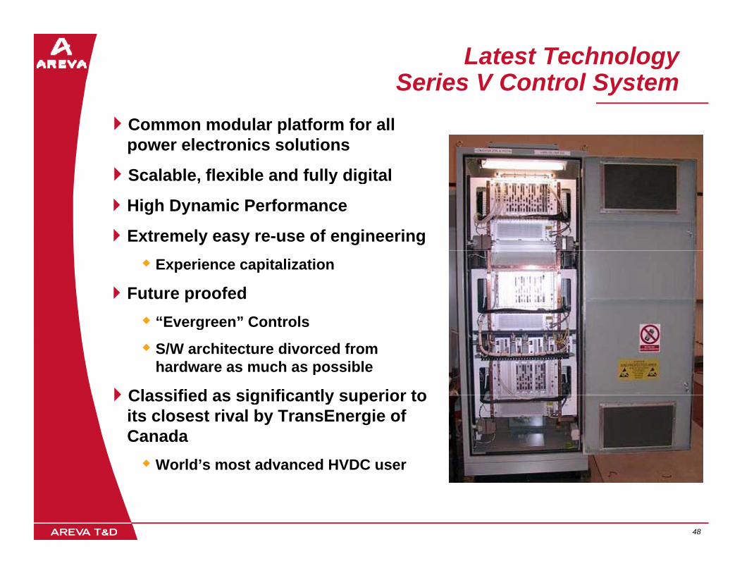
Latest TechnologySeries V Control System
Common modular platform for all power electronics solutions
Scalable flexible and fully digitalScalable, flexible and fully digital
High Dynamic Performance
Extremely easy re-use of engineeringExperience capitalization
Future proofed“Evergreen” ControlsEvergreen Controls
S/W architecture divorced from hardware as much as possible
Classified as significantly superior toClassified as significantly superior to its closest rival by TransEnergie of Canada
World’s most advanced HVDC user
48 48
World s most advanced HVDC user

Series V: Overview of implementationDuplicated system for Back to Back HVDC
49 49

Valve Test Facilities
50 50

Valve Test FacilityEssential to be able to test HVDC and SVC valves to international standards
During development
D i t tDuring contracts
Facility established 1960sOnly 3 similar facilities exist in the worldOnly 3 similar facilities exist in the world
Currently undergoing ~€10M investment
51 51

VSC HVDC
53 53

VSC HVDC SchemeMain Equipment
DC Link Capacitors
Transistor Bridge Converter
DC Chopper, discharge & O/V
protection
Converter Transformer
Bridge ReactorRFI Reactor+
Vdc
0V
FF
DC cableNon-switched
High Frequency
FF_Vdc
High Frequency Filters
Many transistors connected in series
54 54
in series
3-phase bridge, PWM 1- 2kHz
Why VSC HVDC? - 1
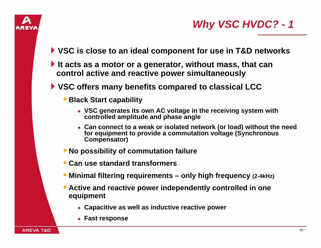
VSC is close to an ideal component for use in T&D networksIt acts as a motor or a generator, without mass, that can control active and reactive power simultaneouslyp yVSC offers many benefits compared to classical LCC
Black Start capabilityVSC t it AC lt i th i i t ithVSC generates its own AC voltage in the receiving system with controlled amplitude and phase angleCan connect to a weak or isolated network (or load) without the need for equipment to provide a commutation voltage (Synchronous Compensator)Compensator)
No possibility of commutation failureCan use standard transformersMinimal filtering requirements – only high frequency (2-4kHz)
Active and reactive power independently controlled in one equipment
55 55
Capacitive as well as inductive reactive powerFast response
Why VSC HVDC? - 2
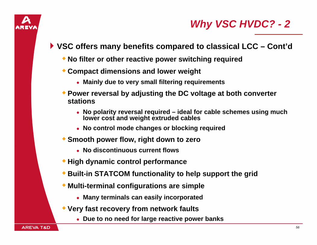
VSC offers many benefits compared to classical LCC Cont’dVSC offers many benefits compared to classical LCC – Cont’dNo filter or other reactive power switching requiredCompact dimensions and lower weight
Mainly due to very small filtering requirements
Power reversal by adjusting the DC voltage at both converter stations
No polarity reversal required – ideal for cable schemes using much lower cost and weight extruded cablesNo control mode changes or blocking required
S th fl i ht d tSmooth power flow, right down to zeroNo discontinuous current flows
High dynamic control performanceBuilt-in STATCOM functionality to help support the gridMulti-terminal configurations are simple
Many terminals can easily incorporated
56 56
y y p
Very fast recovery from network faultsDue to no need for large reactive power banks

Disadvantages of VSC HVDC
Higher capital equipment costT i ll 15%Typically 15%
Higher power loss More than double that of classical LCC, usually 3 timesMore than double that of classical LCC, usually 3 times
EMC issues much more important
Immature technology
Inherently has lower reliabilityDue to much greater component count
100s of small IGBT chips versus 1 thyristor slice
Not used for overhead lines yetMost probably because of problems of protection against lightning
57 57
Most probably because of problems of protection against lightning
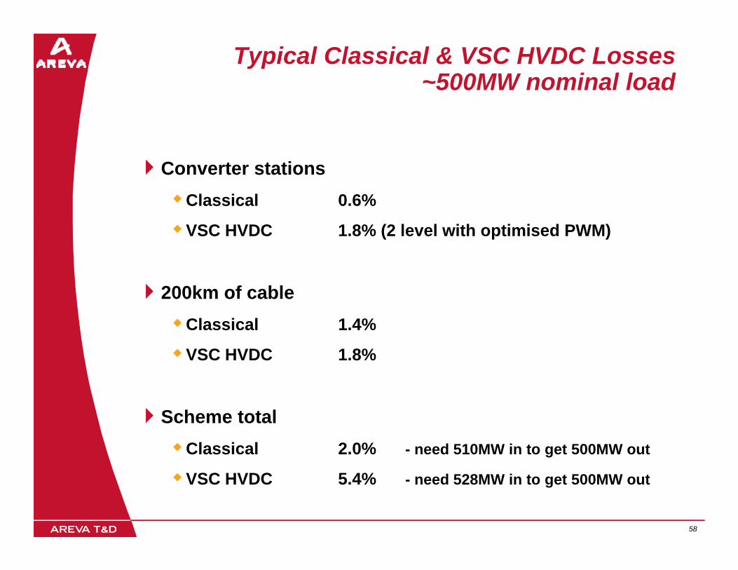
Typical Classical & VSC HVDC Losses~500MW nominal load
Converter stationsClassical 0.6%
VSC HVDC 1.8% (2 level with optimised PWM)
200km of cableCl i l 1 4%Classical 1.4%
VSC HVDC 1.8%
Scheme totalClassical 2.0% - need 510MW in to get 500MW out
58 58
VSC HVDC 5.4% - need 528MW in to get 500MW out

Reliability/Availability IssuesClassical HVDC
Uses single slice thyristors, which are easier to protect: They have a significant surge rating capabilitySwitching is regenerativeSwitching is regenerative
Fewer devices in series and associated auxiliariesState of art is 8.5kV, 125mm diameter devices
Pressure contact double sided cooling keeps silicon cooler
Simple gate drive with low PSU requirements
Less cooling plantLess cooling plantFor devices and the building
Filters are at lower frequencies
More complex transformers
Well proven technologyDeveloped over >40 years
59 59
Developed over >40 years

Reliability/Availability issuesVSC HVDC
E h IGBT i d f ll hiEach IGBT is made from many small chipsVirtually no surge ratingNon-regenerative switching
Devices de saturate under overcurrent- Devices de-saturate under overcurrent
2.5kV devices, therefore many more items to put in seriesPressure contact to emmiter has to be via springs
Th f ff ti l i l id d l dTherefore effectively single sided cooledEven more devices needed to meet ratings
More cooling plant equipment neededF b th d i d b ildiFor both devices and building
Very complex gate drive with high PSU requirementsCreated from switching action
Filters are at higher frequencySimpler transformerAs yet, immature technology
60 60
IGBT chip

Monopole, Bipole and “Bipolar”
MonopoleMonopoleLoss of link if one cable or one leg of converter goes out of service
ClassicalFF F FFF F F
Pole 1 Pole 1
HV Cable
LV Cable
+VClassical
0V
+V
12 pulse bridge
VSC HVDCVSC HVDC
-V6 pulse bridge
61 61
+V and –V equates to “bipolar” operation to create sinewave at the AC sideIt is not a BIPOLE
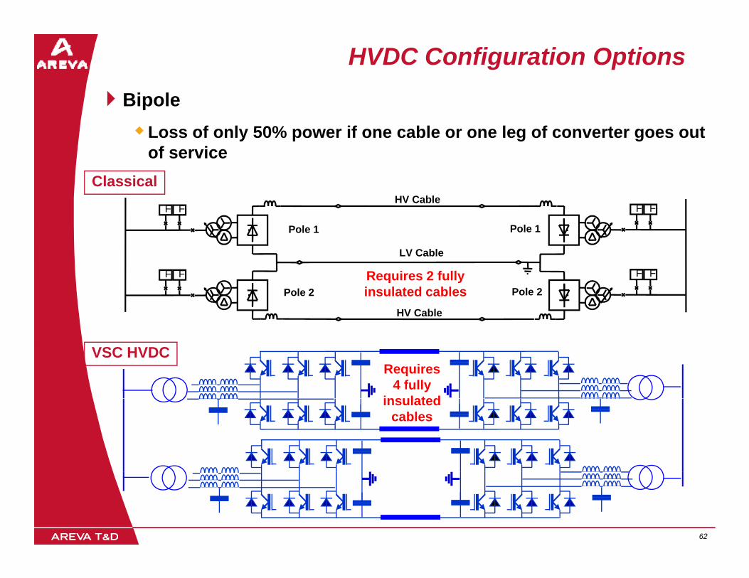
HVDC Configuration OptionsBipolep
Loss of only 50% power if one cable or one leg of converter goes out of service
ClassicalFF F F
Pole 1 Pole 1
HV Cable
LV Cable
Classical
FF F F
Pole 2 Pole 2
LV Cable
HV Cable
Requires 2 fully insulated cables
VSC HVDCRequires
4 fully insulatedinsulated
cables
62 62
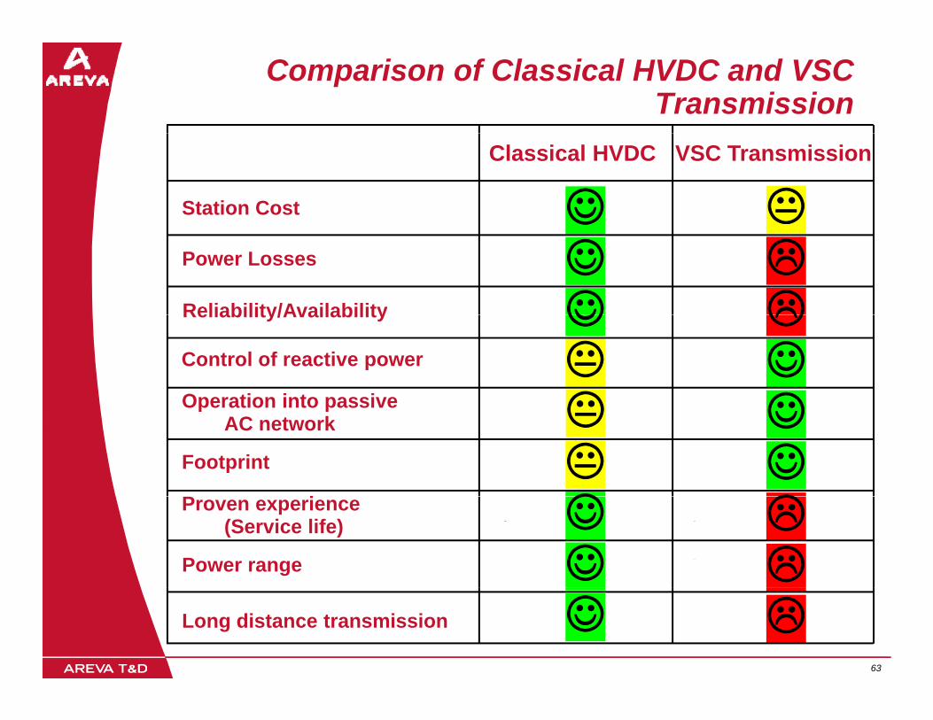
Comparison of Classical HVDC and VSC Transmission
Classical HVDC VSC Transmission
Station Cost ☺☺Power Losses ☺Reliability/Availability ☺Reliability/Availability ☺Control of reactive power ☺Operation into passive ☺Operation into passive
AC network ☺Footprint ☺P i ☺Proven experience
(Service life) ☺Power range ☺
63 63
Long distance transmission ☺