52101HARNESS KIT
3‑PORT ISOLATION MODULE LIGHT SYSTEM
Parts List and Installation Instructions
A DIVISION OF DOUGLAS DYNAMICS, LLC
January 1, 2016Lit. No. 92935, Rev. 01
CAUTIONRead this document before installing the snowplow.
CAUTIONSee your sales outlet/Web site for specific vehicle application recommendations before installation. The online selection tool has specific vehicle and snowplow requirements.
Lit. No. 92935, Rev. 01 2 January 1, 2016
52101
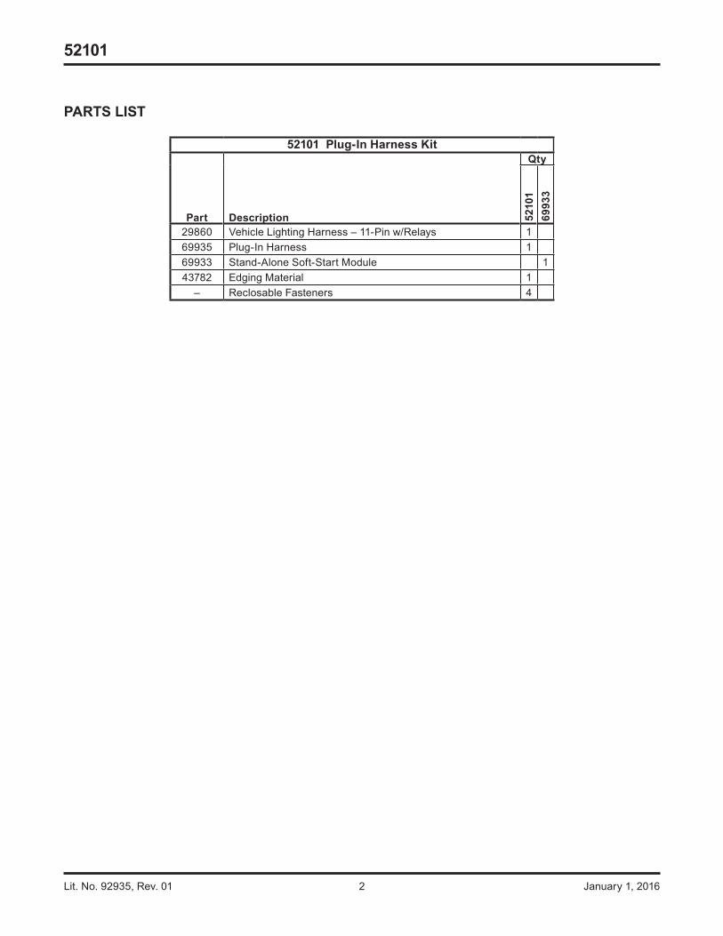
52101 Plug‑In Harness Kit
Part Description
Qty
5210
169
933
29860 Vehicle Lighting Harness – 11-Pin w/Relays 169935 Plug-In Harness 169933 Stand-Alone Soft-Start Module 143782 Edging Material 1
– Reclosable Fasteners 4
PARTS LIST

Lit. No. 92935, Rev. 01 3 January 1, 2016
52101
SAFETY DEFINITIONS
NOTE: Indicates a situation or action that can lead to damage to your snowplow and vehicle or other property. Other useful information can also be described.
FUSES
The snowplow electrical and hydraulic systems contain several blade-style automotive fuses. If a problem should occur and fuse replacement is necessary, the replacement fuse must be of the same type and amperage rating as the original. Installing a fuse with a higher rating can damage the system and could start a fire. Fuse Replacement, including fuse ratings and locations, is located in the Maintenance section of the Owner's Manual.
BATTERY SAFETY
CAUTIONIndicates a potentially hazardous situation that, if not avoided, may result in minor or moderate injury. It may also be used to alert against unsafe practices.
TORQUE CHART
1/4-20 109 1541/4-28 121 1715/16-18 150 2125/16-24 170 2403/8-16 269 3763/8-24 297 4207/16-14 429 6067/16-20
9/16-129/16-185/8-115/8-183/4-103/4-167/8-97/8-14 474 669
644 9091-81-12 704 995
1/2-131/2-20
11.913.724.627.343.6
26.953.393148
49.469.877.9
106.4120.0
8.49.717.419.230.835.049.455.275.385.0
M6 x 1.00
M12 x 1.75
M8 x 1.25
M14 x 2.00
M10 x 1.50M27 x 3.00
M22 x 2.50
M30 x 3.50
M24 x 3.00
M20 x 2.5011.119.538.567107
7.761377811391545
4504285627961117
M33 x 3.50M36 x 4.00
21012701
14681952
325
M16 x 2.00 231167M18 x 2.50 318222
Recommended Fastener Torque Chart
Size SizeTorque (ft-lb)
Grade5
Grade8
Metric Fasteners Class 8.8 and 10.9
These torque values apply to fastenersexcept those noted in the instructions.
Torque (ft-lb)Grade
5Grade
8
Size SizeTorque (ft-lb)
Class8.8
Class10.9
Torque (ft-lb)Class
8.8Class10.9
Inch Fasteners Grade 5 and Grade 8
CAUTIONRead instructions before assembling. Fasteners should be finger tight until instructed to tighten according to the torque chart. Use standard methods and practices when attaching snowplow, including proper personal protective safety equipment.
WARNINGIndicates a potentially hazardous situation that, if not avoided, could result in death or serious personal injury.
CAUTIONBatteries normally produce explosive gases, which can cause personal injury. Therefore, do not allow flames, sparks or lit tobacco to come near the battery. When charging or working near a battery, always cover your face and protect your eyes, and also provide ventilation.• Batteries contain sulfuric acid, which burns
skin, eyes and clothing.• Disconnect the battery before removing or
replacing any electrical components.

Lit. No. 92935, Rev. 01 4 January 1, 2016
52101
TYPICAL 2‑PLUG, 3‑PORT MODULE SYSTEM DIAGRAM
Fact
ory
Vehi
cle
Har
ness
Fact
ory
Vehi
cle
Har
ness
BAT
BLK
REDB
atte
ry
10.0
- A
mp
Fuse
s(S
now
plow
Pa
rk/T
urn
& S
now
plow
C
ontro
l)
Turn
Sig
nal
Con
figur
atio
n Pl
ug
Plug
-In
Har
ness
Vehi
cle
Ligh
ting
Har
ness
(11-
Pin)
Vehi
cle
Con
trol
Har
ness
Vehi
cle
Hea
dlam
ps
Park
/Tur
n La
mps
Vehi
cle
Hea
dlam
ps
Park
/Tur
n La
mps Ve
hicl
e B
atte
ry C
able
To Snowplow Control
To Switched Accessory
Fire Wall
3-Po
rt M
odul
e
RE
D
Pin
k W
ires:
D
edic
ated
DR
L A
ssem
bly
Con
figur
atio
n P
lug
Soft-
Star
t M
odul
e
CAUTIONOn 2‑plug electrical systems, plug covers shall be used whenever snowplow is disconnected. Vehicle Battery Cable is 12‑volt unfused source.

Lit. No. 92935, Rev. 01 5 January 1, 2016
52101
TYPICAL 3‑PLUG, 3‑PORT MODULE SYSTEM DIAGRAM
Fact
ory
Vehi
cle
Har
ness
Fact
ory
Vehi
cle
Har
ness
RE
D
BLK
RED/GRN
RED/BRN
RE
D
BLK/ORN
BLK
/OR
N
RED
BLK/ORN
Ada
pter
15-A
mp
Fuse
(Par
k/Tu
rn)
Bat
tery Tu
rn S
igna
l C
onfig
urat
ion
Plug
(not
use
d)
Vehi
cle
Ligh
ting
Har
ness
(11-
Pin)
Vehi
cle
Con
trol
Har
ness
(3-P
in)
Vehi
cle
Hea
dlam
ps
Vehi
cle
Hea
dlam
ps
Park
/Tur
n La
mps
Park
/Tur
n La
mpsVe
hicl
e B
atte
ry C
able
Mot
orR
elay
Bat
tery
Cab
leTo Snowplow Control To Switched Accessory
Fire Wall
3-Po
rt M
odul
e
7.5-
Am
p Fu
se (S
traig
ht B
lade
Con
trol)
Pin
k W
ires:
D
edic
ated
DR
L A
ssem
bly
Con
figur
atio
n P
lug
10.0
- A
mp
Fuse
s(S
now
plow
Pa
rk/T
urn
& S
now
plow
C
ontro
l)
Plug
-In H
arne
ssSo
ft-St
art
Mod
ule
Lit. No. 92935, Rev. 01 6 January 1, 2016
52101
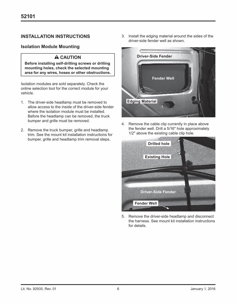
INSTALLATION INSTRUCTIONS
Isolation Module Mounting
Isolation modules are sold separately. Check the online selection tool for the correct module for your vehicle.
1. The driver-side headlamp must be removed to allow access to the inside of the driver-side fender where the isolation module must be installed. Before the headlamp can be removed, the truck bumper and grille must be removed.
2. Remove the truck bumper, grille and headlamp trim. See the mount kit installation instructions for bumper, grille and headlamp trim removal steps.
3. Install the edging material around the sides of the driver-side fender well as shown.
4. Remove the cable clip currently in place above the fender well. Drill a 5/16" hole approximately 1/2" above the existing cable clip hole.
5. Remove the driver-side headlamp and disconnect the harness. See mount kit installation instructions for details.
CAUTIONBefore installing self‑drilling screws or drilling mounting holes, check the selected mounting area for any wires, hoses or other obstructions.
Driver‑Side Fender
Edging Material
Fender Well
Driver‑Side Fender
Fender Well
Existing Hole
Drilled hole
Lit. No. 92935, Rev. 01 7 January 1, 2016
52101
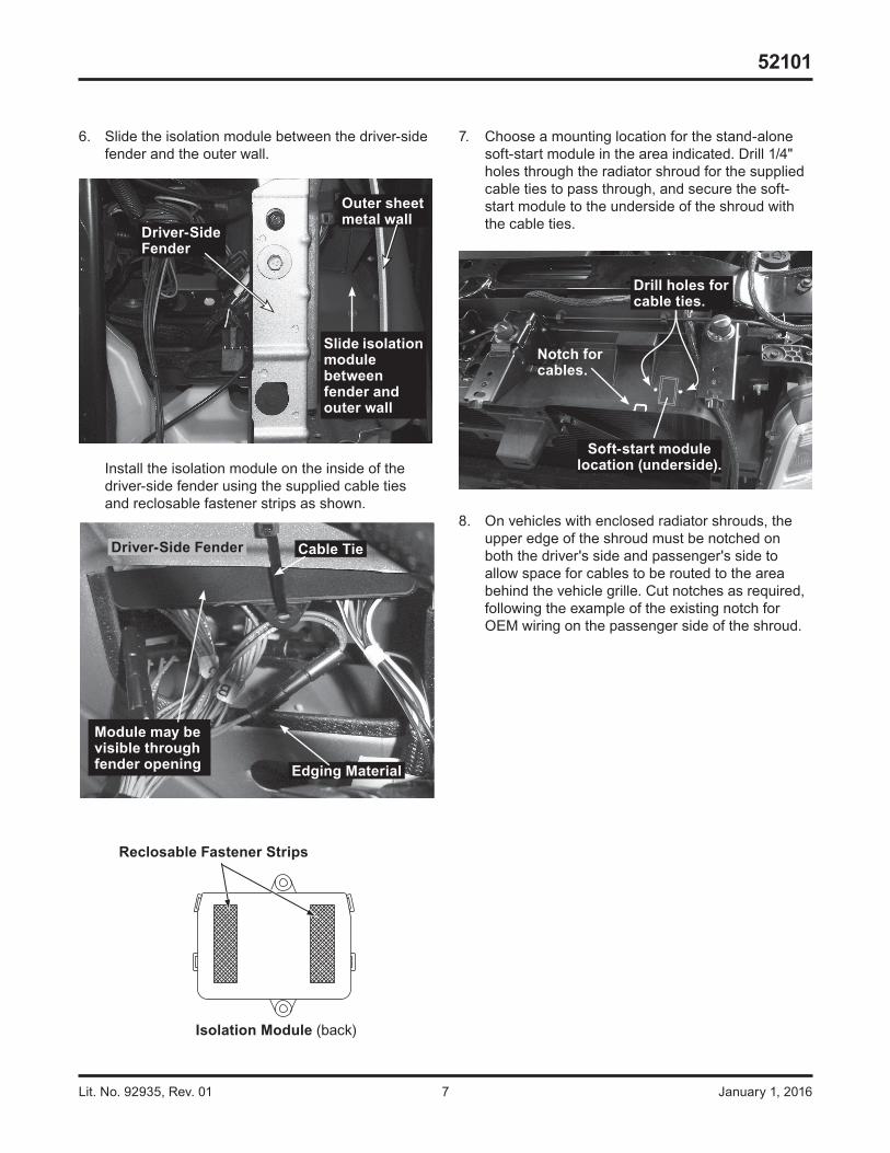
7. Choose a mounting location for the stand-alone soft-start module in the area indicated. Drill 1/4" holes through the radiator shroud for the supplied cable ties to pass through, and secure the soft-start module to the underside of the shroud with the cable ties.
8. On vehicles with enclosed radiator shrouds, the upper edge of the shroud must be notched on both the driver's side and passenger's side to allow space for cables to be routed to the area behind the vehicle grille. Cut notches as required, following the example of the existing notch for OEM wiring on the passenger side of the shroud.
6. Slide the isolation module between the driver-side fender and the outer wall.
Install the isolation module on the inside of the driver-side fender using the supplied cable ties and reclosable fastener strips as shown.
Module may be visible through fender opening Edging Material
Cable TieDriver‑Side Fender
Driver‑Side Fender
Slide isolation module between fender and outer wall
Outer sheet metal wall
Reclosable Fastener Strips
Isolation Module (back)
Notch for cables.
Soft‑start module location (underside).
Drill holes for cable ties.

Lit. No. 92935, Rev. 01 8 January 1, 2016
52101
TWO‑PLUG SYSTEM
Vehicle Battery Cable Installation
NOTE: When instructed, make all snowplow battery cable connections to the auxiliary battery, if vehicle is so equipped.
NOTE: Use dielectric grease on all electrical connections to prevent corrosion. Fill receptacles and lightly coat ring terminals before assembly.
CAUTIONBatteries normally produce explosive gases, which can cause personal injury. Therefore, do not allow flames, sparks or lit tobacco to come near the battery. When charging or working near a battery, always cover your face and protect your eyes, and also provide ventilation.• Batteries contain sulfuric acid, which burns
skin, eyes and clothing.• Disconnect the battery before removing or
replacing any electrical components.
1. Turn OFF the vehicle ignition.
2. Disconnect both the NEGATIVE (–) and the POSITIVE (+) battery cables.
3. Route the supplied vehicle battery cable from the grille or bumper to the battery, avoiding any sharp edges and hot or moving parts. Cable tie only the end section closest to the grille.
4. Route the red wire from the vehicle battery cable to the POSITIVE (+) battery terminal. Do not connect at this time.
5. Route the black wire from the vehicle battery cable to the NEGATIVE (–) battery terminal. Do not connect at this time. The 4-position connector from the vehicle battery cable will connect to the mating connector (labeled "BAT") on the end of the vehicle control harness.

Lit. No. 92935, Rev. 01 9 January 1, 2016
52101
Vehicle Lighting and Vehicle Control Harness Installation
1. Route both harnesses around or through the radiator bulkhead to the isolation module.
2. Connect the 4-position connector from the vehicle lighting harness to the matching 4-position connector from the vehicle control harness.
3. Connect the vehicle lighting harness to position "A" on the isolation module.
4. Route the end of the vehicle control harness with the white 4-pin connector to the fire wall. Connect the black 4-position connector (labeled "BAT") from the end of the vehicle control harness to the 4-position connector from the vehicle battery cable. Do not cable tie the harness at this time.
5. On the driver's side, locate an existing hole through the fire wall for the vehicle control harness. If access through the fire wall does not exist, drill a 5/8" hole through the fire wall in a convenient location away from sharp edges and hot or moving parts.
6. Push the braided harness breakout with the cab control connector through the fire wall hole into the cab. Use a grommet, existing plug cover or proper chafing material to protect the harness where it passes through the fire wall. Route the harness to the selected control mounting location. To mount the control, follow the instructions supplied with the control.
7. Locate an accessory wire controlled by the ignition switch. Acceptable accessory wires show +12V when the ignition switch is turned ON, and 0V when it is OFF.
8. Route the red "ACC" wire from the vehicle control harness to this location and trim away excess length.
9. Following the recommended splicing procedure given at the end of this document, splice the red "ACC" wire into the switched accessory wire using the supplied parallel splices and heatshrink tubing. CAUTION
Before installing self‑drilling screws or drilling mounting holes, check the selected mounting area for any wires, hoses or other obstructions.

Lit. No. 92935, Rev. 01 10 January 1, 2016
52101
THREE‑PLUG SYSTEM
Motor Relay and Vehicle Battery Cable Installation
NOTE: When instructed, make all snowplow battery cable connections to the auxiliary battery, if vehicle is so equipped.
1. Turn OFF the vehicle ignition.
2. Disconnect both the NEGATIVE (–) and the POSITIVE (+) battery cables.
3. Choose a location on the vehicle where the motor relay will be protected from road splash and debris. Motor relay must be within 18" of the vehicle battery. (The motor relay can be farther from the battery if the battery cable provided with either the plug-in harness or adapter kit is longer than 22".)
NOTE: Position motor relay terminals up, horizontal or in between.
4. Drill two 9/32" mounting holes using the motor relay mounting plate as a template. Mount the motor relay using 1/4" x 3/4" cap screws, washers and locknuts.
5. Route the supplied vehicle battery cable from the grille or bumper to the location chosen for mounting the motor relay, avoiding any sharp edges and hot or moving parts. Cable tie only the end section closest to the grille.
6. Attach the red wire from the vehicle battery cable to one of the large terminals on the motor relay. Secure with a lock washer and 5/16" nut, and tighten to a maximum of 35 in-lb.
NOTE: Use dielectric grease on all electrical connections to prevent corrosion. Fill receptacles and lightly coat ring terminals before assembly.
7. Route the black wire from the vehicle battery cable to the NEGATIVE (–) battery terminal. Do not connect at this time. The black/orange wire from the vehicle battery cable will connect to the mating connector on the vehicle control harness.
CAUTIONOvertightening terminal attaching nuts may cause seal failure, resulting in premature failure of motor relay.
Red Vehicle Battery Cable(Tighten nut to max. 35 in-lb)
CAUTIONBefore installing self‑drilling screws or drilling mounting holes, check the selected mounting area for any wires, hoses or other obstructions.
CAUTIONBatteries normally produce explosive gases, which can cause personal injury. Therefore, do not allow flames, sparks or lit tobacco to come near the battery. When charging or working near a battery, always cover your face and protect your eyes, and also provide ventilation.• Batteries contain sulfuric acid, which burns
skin, eyes and clothing.• Disconnect the battery before removing or
replacing any electrical components.

Lit. No. 92935, Rev. 01 11 January 1, 2016
52101
Vehicle Lighting and Vehicle Control Harness Installation
Vehicle lighting and vehicle control harnesses are designed to plug into one another when the snowplow is not attached. Plug the harnesses together before cable tying them to ensure adequate length.
1. Route both harnesses around or through the radiator bulkhead to the isolation module.
2. Make the following connections:• 10-position connector from vehicle control
harness to 10-position connector from adapter included with harness kit.
• Single-wire connector from vehicle control harness to single-wire connector from adapter included with harness kit.
• 4-position connector from adapter included with hydraulic kit to 4-position connector from vehicle lighting harness.
• Vehicle lighting harness to position "A" on the isolation module.
NOTE: The 3‑position connector on the vehicle control harness will not be used. Cover the terminals with dielectric grease and cap off with electrical tape.
3. Route the end of the vehicle control harness with the white 6-pin connector to the fire wall. Route the vehicle control harness breakout with four wires to the motor relay.
Secure the brown/red and black/orange wires to the small terminals of the motor relay with #10 lock washers and 10-32 nuts, and tighten to a maximum 15 in-lb.
4. Connect the single-wire connector (black/orange wire) from the vehicle control harness breakout to the single-wire connector (black/orange wire) from the vehicle battery cable. Do not cable tie the harness at this time.
5. Attach the supplied red battery cable and the red/green wire from the vehicle control harness to a large terminal on the motor relay with a lock washer and 5/16" nut and tighten to a maximum 35 in-lb. Route the supplied red battery cable between motor relay terminal and POSITIVE (+) battery terminal, avoiding sharp edges and hot or moving parts. Do not connect at this time.
CAUTIONOvertightening terminal attaching nuts may cause seal failure, resulting in premature failure of motor relay.
Red Battery Cable
Tighten to max. 35 in-lb
Brown/Red Wire
Vehicle Control Harness
Black/Orange Wire from Vehicle Control Harness
Tighten to max. 15 in-lb
Red/Green Wire

Lit. No. 92935, Rev. 01 12 January 1, 2016
52101
PLUG COVER INSTALLATION
Stretch the rectangular opening of the plug cover strap over the end of the vehicle battery cable. Place the plug cover over the molded plug when snowplow is not in use.
PLUG‑IN HARNESS INSTALLATION
1. Remove the headlamp or headlamp housing connectors. Connect the plug-in harness to the mating connectors removed from the headlamps or headlamp housings. Connect the plug-in harness to the mating connections at the headlamps or headlamp housings.
2. Route the plug-in harness to the isolation module. Connect the plug-in harness to the module by matching harness connector B with module port B and harness connector C with module port C.
3. Connect the 4-position connector on the vehicle lighting harness to the matching 4-position connector on the plug-in harness.
4. Connect the single-wire connector from the vehicle lighting harness to the single-wire connector from the plug-in harness.
5. Cable tie the vehicle control harness, vehicle lighting harness, and plug-in harness away from any sharp, hot or moving parts.
6. On the driver's side, locate an existing hole through the fire wall for the vehicle control harness. If access through the fire wall does not exist, drill a 5/8" hole through the fire wall of the vehicle in a convenient location away from sharp edges and hot or moving parts.
7. Locate an accessory wire controlled by the ignition switch. Acceptable accessory wires show +12V when the ignition switch is ON, and 0V when it is OFF.
8. Route the red wire from the vehicle control harness to this location and trim away excess length.
9. Following the recommended splicing procedure given at the end of this document, splice the red wire into the switched accessory wire using the supplied parallel splices and heatshrink tubing.
CAUTIONBefore installing self‑drilling screws or drilling mounting holes, check the selected mounting area for any wires, hoses or other obstructions.
Molded Plug
Plug Cover

Lit. No. 92935, Rev. 01 13 January 1, 2016
52101
TURN SIGNAL CONFIGURATION PLUG
Mate the turn signal configuration plug located on the plug-in harness.
If the isolation module is installed on the driver's side, mate the plug so that the wire colors match (green to green and blue to blue). If the module is installed on the passenger's side, mate the plug so that the wire colors are opposite (green to blue).
WARNINGIf the turn signal configuration plug is mated incorrectly, the turn signals will be reversed between the vehicle and the snowplow.
Turn Signal Configuration Plug
Driver-Side Module Passenger-Side ModuleGRN GRN
BLU BLU
BLU GRN
GRN BLU
B – Green & Red Wires C – Blue & Red Wires
BATTERY CONNECTIONS
NOTE: Cable tie the control harness and accessory tap away from the brake, clutch, gas or parking brake pedals, and any moving parts.
1. Attach the POSITIVE (+) OEM cable to the battery. Attach the RED vehicle battery cable to the POSITIVE (+) battery terminal following OEM battery cable connection recommendations.
2. Attach the NEGATIVE (–) OEM cable to the battery. Attach the BLACK vehicle battery cable to the NEGATIVE (–) battery terminal following OEM battery cable connection recommendations.
DRL CONFIGURATION PLUG
The pink wires and plugs on the plug-in harness are used on vehicles with dedicated DRL lamp assemblies. Place the vehicle in DRL mode and check for voltage on either the DRL 1 or DRL 2 lead. Connect the single-pin mating plug to the lead with voltage during DRL operation.
DRL Configuration Plug
Voltage on DRL 1
Voltage on DRL 2
DRL 1
DRL 2
DRL 2
DRL 1

Lit. No. 92935, Rev. 01 14 January 1, 2016
52101
9. Check the circuits for continuity.
10. Cover the splice with heatshrink tubing. The tubing should extend beyond the splice on both sides.
11. Using a hot-air source, starting in the center and working out to either side, apply heat until the tubing recovers and glue can be seen around the edges. Allow the tubing to cool before handling.
NOTE: The splices supplied will accommodate 18‑gauge wires as shown. For larger gauge wires, cut the wire, strip the ends 3/8" to 1/2" and twist together. Apply solder to the splice and cover with heatshrink tubing.
Crimp and solder each splice.
From OEMvehicle harnessFrom controlharness
Splicing Procedure
Butt Splice
5/16"
Insert wires into splice.
Vehicle switchedaccessory wire
Cover the splice with heatshrink tubing.Using a hot-air source, apply heat until tubing
recovers and glue can be seen around theedges. Allow tubing to cool before handling.
Heatshrink tubingGlue
RECOMMENDED SPLICING PROCEDURE
1. Locate wire to be spliced into.
2. Cut wire at least 1-1/2" from any other splice, connector, or terminal. If wires are covered by tubing or braid, remove enough of it to achieve the minimum clearance required.
3. Strip away 5/16" of insulation from the ends of the wires to be spliced.
4. Slide two wires into one end of the supplied parallel splice.
5. Place a piece of heatshrink tubing (3/16" x 1-1/4" long) over the remaining wire to be spliced. Cut tubing into 1-1/4" lengths if required.
6. Insert the wire into the open end of the splice and crimp using an appropriate crimp tool. One or two crimps may be necessary to ensure a good connection. No wire strands should be visible outside of the splice.
7. Preheat a soldering tool for at least one minute to help promote even solder flow.
8. Apply heat to the splice. Avoid heating too close to the insulation. Apply solder to the wires. Use just enough solder to produce an even flow through the splice. Use rosin core solder ONLY. Do not use acid core solder.
NOTE: Avoid using an excessive amount of solder, as it can result in wicking. Wicking occurs when solder travels up the wire core. This may cause the wire to become stiff or brittle, which could lead to a broken or open circuit.
The company reserves the right under its product improvement policy to change construction or design details and furnish equipment when so altered without reference to illustrations or specifications used. This equipment manufacturer or the vehicle manufacturer may require or recommend optional equipment for snow removal. Do not exceed vehicle ratings with a snowplow. The company offers a limited warranty for all snowplows and accessories. See separately printed page for this important information.
Printed in U.S.A.

![[fa] Validity date from کشور [fa] Viet Nam 00269 [FA ... · 5 / 33 [fa] List in force شماره تایید نام شهر [fa] Regions [fa] Activities [fa] Remark [fa] Date of](https://static.cupdf.com/doc/110x72/5e0e403e2c91e71788574ed3/fa-validity-date-from-fa-viet-nam-00269-fa-5-33-fa-list-in.jpg)