User’s Manual IM 34M06H43-01E FA Link H Module Fiber-optic FA Link H Module Model: F3LP02-0N, F3LP12-0N IM 34M06H43-01E 4th Edition Yokogawa Electric Corporation

Welcome message from author
This document is posted to help you gain knowledge. Please leave a comment to let me know what you think about it! Share it to your friends and learn new things together.
Transcript
User’s Manual
IM 34M06H43-01E
FA Link H Module Fiber-optic FA Link H Module Model: F3LP02-0N, F3LP12-0N
IM 34M06H43-01E 4th Edition
Yokogawa Electric Corporation

Blank Page
IM 34M06H43-01E 4th Edition : Jan. 2012-00
i
Media No. IM 34M06H43-01E (CD) 4th Edition :Jan. 2012 (AR) All Rights Reserved Copyright © 2012, Yokogawa Electric Corporation
Applicable Product: - Model Code : F3LP02-0N - Name : FA Link H Module - Model Code : F3LP12-0N - Name : Fiber-optic FA Link H Module
The document number for this manual is given below. Refer to the document number when purchasing additional copies of this manual or in any other inquiries. - Document No. : IM 34M06H43-01E
IM 34M06H43-01E 4th Edition : Jan. 2012-00
ii
Important
About This Manual - This Manual should be passed on to the end user. - Before using the controller, read this manual thoroughly to have a clear understanding
of the controller. - This manual explains the functions of this product, but there is no guarantee that they
will suit the particular purpose of the user. - Under absolutely no circumstances may the contents of this manual be transcribed
or copied, in part or in whole, without permission. - The contents of this manual are subject to change without prior notice. - Every effort has been made to ensure accuracy in the preparation of this manual.
However, should any errors or omissions come to the attention of the user, please contact the nearest Yokogawa Electric representative or sales office.
Safety Precautions when Using/Maintaining the Product - The following safety symbols are used on the product as well as in this manual.
Danger. This symbol on the product indicates that the operator must follow the instructions laid out in this user’s manual to avoid the risk of personnel injuries, fatalities, or damage to the instrument. The manual describes what special care the operator must exercise to prevent electrical shock or other dangers that may result in injury or the loss of life.
Protective Ground Terminal. Before using the instrument, be sure to ground this terminal.
Function Ground Terminal. Before using the instrument, be sure to ground this terminal.
Alternating current. Indicates alternating current.
Direct current. Indicates direct current.
IM 34M06H43-01E 4th Edition : Jan. 2012-00
iiiThe following symbols are used only in the user’s manual.
WARNING Indicates a “Warning”. Draws attention to information essential to prevent hardware damage, software damage or system failure.
CAUTION Indicates a “Caution” Draws attention to information essential to the understanding of operation and functions.
TIP Indicates a “TIP” Gives information that complements the present topic.
SEE ALSO Indicates a “SEE ALSO” reference. Identifies a source to which to refer.
- For the protection and safe use of the product and the system controlled by it, be
sure to follow the instructions and precautions on safety stated in this manual whenever handling the product. Take special note that if you handle the product in a manner other than prescribed in these instructions, the protection feature of the product may be damaged or impaired. In such cases, Yokogawa cannot guarantee the quality, performance, function and safety of the product.
- When installing protection and/or safety circuits such as lightning protection devices and equipment for the product and control system as well as designing or installing separate protection and/or safety circuits for fool-proof design and fail-safe design of processes and lines using the product and the system controlled by it, the user should implement it using devices and equipment, additional to this product.
- If component parts or consumable are to be replaced, be sure to use parts specified by the company.
- This product is not designed or manufactured to be used in critical applications which directly affect or threaten human lives and safety — such as nuclear power equipment, devices using radioactivity, railway facilities, aviation equipment, air navigation facilities, aviation facilities or medical equipment. If so used, it is the user’s responsibility to include in the system additional equipment and devices that ensure personnel safety.
- Do not attempt to modify the product.
Exemption from Responsibility - Yokogawa Electric Corporation (hereinafter simply referred to as Yokogawa Electric)
makes no warranties regarding the product except those stated in the WARRANTY that is provided separately.
- Yokogawa Electric assumes no liability to any party for any loss or damage, direct or indirect, caused by the user or any unpredictable defect of the product.

IM 34M06H43-01E 4th Edition : Jan. 2012-00
iv
Software Supplied by the Company - Yokogawa Electric makes no other warranties expressed or implied except as
provided in its warranty clause for software supplied by the company. - Use the software with one computer only. You must purchase another copy of the
software for use with each additional computer. - Copying the software for any purposes other than backup is strictly prohibited. - Store the original media, such as floppy disks, that contain the software in a safe
place. - Reverse engineering, such as decompiling of the software, is strictly prohibited. - No portion of the software supplied by Yokogawa Electric may be transferred,
exchanged, or sublet or leased for use by any third party without prior permission by Yokogawa Electric.
IM 34M06H43-01E 4th Edition : Jan. 2012-00
v
General Requirements for Using the FA-M3
Avoid installing the FA-M3 in the following locations: - Where the instrument will be exposed to direct sunlight, or where the operating
temperature exceeds the range 0C to 55C (32F to 131F). - Where the relative humidity is outside the range 10 to 90%, or where sudden
temperature changes may occur and cause condensation. - Where corrosive or flammable gases are present. - Where the instrument will be exposed to direct mechanical vibration or shock. - Where the instrument may be exposed to extreme levels of radioactivity.
Select an appropriate field wiring material: - USE COPPER CONDUCTORS ONLY Use copper wire with temperature ratings greater than 75C.
Securely tighten screws: - Securely tighten module mounting screws and terminal screws to avoid problems
such as faulty operation. - Tighten terminal block screws with the correct tightening torque as given in this
manual.
Securely lock connecting cables: - Securely lock the connectors of cables, and check them thoroughly before turning
on the power.
Interlock with emergency-stop circuitry using external relays: - Equipment incorporating the FA-M3 must be furnished with emergency-stop circuitry
that uses external relays. This circuitry should be set up to interlock correctly with controller status (stop/run).
Ground for low impedance: - For safety reasons, connect the [FG] grounding terminal to a Japanese Industrial
Standards (JIS) Class 3 Ground. For compliance to CE Marking, use cables such as twisted cables which can ensure low impedance even at high frequencies for grounding.
*1 Japanese Industrial Standard (JIS) Class D Ground means grounding resistance of 100Ω max.
Configure and route cables with noise control considerations: - Perform installation and wiring that segregates system parts that may likely become
noise sources and system parts that are susceptible to noise. Segregation can be achieved by measures such as segregating by distance, installing a filter or segregating the grounding system.
Configure for CE Marking Conformance: - For compliance with CE Marking, perform installation and cable routing according to
the description on compliance to CE Marking in the “Hardware Manual” (IM34M06C11-01E).
IM 34M06H43-01E 4th Edition : Jan. 2012-00
vi
Keep spare parts on hand: - Stock up on maintenance parts including spare modules, in advance. - Preventive maintenance (replacement of the module or its battery) is required for
using the module beyond 10 years. For enquiries on battery replacement service, contact your nearest Yokogawa Electric representative or sales office. (The module has a built-in lithium battery. Lithium batteries may exhibit decreased voltage, and in rare cases, electrolyte leakage problems after ten years.)
Discharge static electricity before operating the system: - Because static charge can accumulate in dry conditions, first touch grounded metal
to discharge any static electricity before touching the system.
Never use solvents such as paint thinner for cleaning: - Gently clean the surfaces of the FA-M3 with a cloth that has been soaked in water
or a neutral detergent and wringed. - Do not use volatile solvents such as benzine or paint thinner or chemicals for
cleaning, as they may cause deformity, discoloration, or malfunctioning.
Avoid storing the FA-M3 in places with high temperature or humidity: - Since the CPU module has a built-in battery, avoid storage in places with high
temperature or humidity. - Since the service life of the battery is drastically reduced by exposure to high
temperatures, take special care (storage temperature should be from –20C to 75C).
- There is a built-in lithium battery in a CPU module and temperature control module which serves as backup power supply for programs, device information and configuration information. The service life of this battery is more than 10 years in standby mode at room temperature. Take note that the service life of the battery may be shortened when installed or stored at locations of extreme low or high temperatures. Therefore, we recommend that modules with built-in batteries be stored at room temperature.
Always turn off the power before installing or removing modules: - Failing to turn off the power supply when installing or removing modules, may result
in damage.
Do not touch components in the module: - In some modules you can remove the right-side cover and install ROM packs or
change switch settings. While doing this, do not touch any components on the printed-circuit board, otherwise components may be damaged and modules may fail to work.
Do not use unused terminals: - Do not connect wires to unused terminals on a terminal block or in a connector.
Doing so may adversely affect the functions of the module.

IM 34M06H43-01E 4th Edition : Jan. 2012-00
vii
Waste Electrical and Electronic Equipment Waste Electrical and Electronic Equipment (WEEE), Directive 2002/96/EC (This directive is only valid in the EU.) This product complies with the WEEE Directive (2002/96/EC) marking requirement. The following marking indicates that you must not discard this electrical/electronic product in domestic household waste. Product Category With reference to the equipment types in the WEEE directive Annex 1, this product is classified as a “Monitoring and Control instrumentation” product. Do not dispose in domestic household waste. When disposing products in the EU, contact your local Yokogawa Europe B. V. office.
How to Dispose of the Battery Used in This Product The following description about the new Battery Directive 2006/66/EC is only valid in the EU. This product uses an embedded battery, which cannot be removed by a customer and should be disposed of together with the product. Do not dispose in domestic household waste. When disposing products in the EU, contact your local Yokogawa Europe B. V. office. Battery category: Lithium battery
Note: With reference to Annex II of the new Battery Directive 2006/66/EC, the above symbol indicates obligatory separate collection.
IM 34M06H43-01E 4th Edition : Jan. 2012-00
viii
Introduction
Overview of the Manual FA Links are networks through which data are exchanged between FA-M3 systems. Data link is achieved through link relays and link registers on these FA links.
How to Read this Manual The FA Link H Module (F3LP02-0N) and Fiber-optic FA Link H Module (F3LP12-0N) can operate in normal mode or high speed mode. You should read different chapters for each mode. To configure a system in normal mode, read Chapters 1 to 6 and Chapter 8. To configure a system in high speed mode, in addition to Chapters 1 to 5 and Chapter 8, you should also read Chapter 7, "High Speed Mode". Chapter 7 discusses features of high speed mode, which differ from normal mode.
Other User Manuals The manual(s) to be read depends on the CPU module to be used. You should read the latest versions of the following manuals, as required.
F3SP71F3SP76
For Functions: - Sequence CPU Instruction Manual – Functions (for F3SP71-4N/4S, F3SP76-
7N/7S) (IM34M06P15-01E) - Sequence CPU – Network Functions (for F3SP71-4N/4S, F3SP76-7N/7S)
(IM34M06P15-02E)
For ladder programming: - FA-M3 Programming Tool WideField3 (IM34M06Q16-01E, -02E, -03E, -04E)
F3SP66F3SP67
For Functions: - Sequence CPU – Functions (for F3SP66-4S, F3SP67-6S) (IM34M06P14-01E) - Sequence CPU – Network Functions (for F3SP66-4S, F3SP67-6S) (IM34M06P14-
02E)
For ladder programming: - FA-M3 Programming Tool WideField2 (IM34M06Q15-01E) - FA-M3 Programming Tool WideField3 (IM34M06Q16-01E, -02E, -03E, -04E)
IM 34M06H43-01E 4th Edition : Jan. 2012-00
ix
F3SP28F3SP38
F3SP22F3SP58F3SP59
F3SP53
For Functions:
- Sequence CPU – Functions (for F3SP22-0S, F3SP28-3N/3S, F3SP38-6N/6S, F3SP53-4H/4S, F3SP58-6H/6S, F3SP59-7S) (IM34M06P13-01E)
For ladder programming: - FA-M3 Programming Tool WideField2 (IM34M06Q15-01E) - FA-M3 Programming Tool WideField3 (IM34M06Q16-01E, -02E, -03E, -04E)
F3SP08F3SP05 F3SP21
F3SP25F3SP35
For Functions: - Sequence CPU – Functions (for F3SP21, F3SP25, F3SP35) (IM34M06P12-02E)
For ladder programming: - FA-M3 Programming Tool WideField2 (IM34M06Q15-01E) - FA-M3 Programming Tool WideField3 (IM34M06Q16-01E, -02E, -03E, -04E)
F3BP20F3BP30
For Functions: - BASIC CPU Modules and YM-BASIC/FA Programming Language
(IM34M06Q22-01E)
For BASIC programming: - BASIC Programming Tool M3 for Windows (IM 34M06Q22-02E)
Common for all sequence CPU modules For the FA-M3 specifications and configurations*1, installation and wiring, test run, maintenance, and module installation limits for the whole system: *1: Refer to the relevant product manuals for specifications except for power supply modules, base modules,
input/output modules, cables and terminal units.
- Hardware Manual (IM 34M06C11-01E)

IM 34M06H43-01E 4th Edition : Jan. 2012-00
x
Copyrights and Trademarks
Copyrights Copyrights of the programs and online manual included in this CD-ROM belong to Yokogawa Electric Corporation. This online manual may be printed but PDF security settings have been made to prevent alteration of its contents. This online manual may only be printed and used for the sole purpose of operating this product. When using a printed copy of the online manual, pay attention to possible inconsistencies with the latest version of the online manual. Ensure that the edition agrees with the latest CD-ROM version. Copying, passing, selling or distribution (including transferring over computer networks) of the contents of the online manual, in part or in whole, to any third party, is strictly prohibited. Registering or recording onto videotapes and other media is also prohibited without expressed permission of Yokogawa Electric Corporation.
Trademarks The trade names and company names referred to in this manual are either trademarks or registered trademarks of their respective companies.
TOC-1
IM 34M06H43-01E 4th Edition : Jan. 2012-00
CONTENTS Applicable Product ....................................................................................i Important ...................................................................................................ii Introduction.............................................................................................vii Copyrights and Trademarks .................................................................viii 1. Overview ....................................................................................... 1-1
1.1 F3LP02-0N and F3LP12-0N Modules ..................................................... 1-1 1.2 Operation Mode ....................................................................................... 1-1 1.3 Link Device............................................................................................... 1-1 1.4 System Configuration ............................................................................. 1-2
1.4.1 Single-layer System ..................................................................... 1-2
1.4.2 Multi-layer System........................................................................ 1-3
1.5 RAS Function........................................................................................... 1-4
2. Specifications............................................................................... 2-1 2.1 Model Names and Specification Codes ................................................ 2-1 2.2 Operating Environment .......................................................................... 2-1 2.3 Performance Specifications ................................................................... 2-1 2.4 Cable Specifications ............................................................................... 2-2
2.4.1 Specifications of Twisted Pair Cables .......................................... 2-2
2.4.2 Specifications for Fiber Optic Cables ........................................... 2-2 2.5 External Dimensions............................................................................... 2-8
F3LP02-0N ........................................................................................... 2-8
F3LP12-0N ........................................................................................... 2-8
3. Setup and Connection of Modules ............................................. 3-1 3.1 Startup Procedures ................................................................................. 3-1 3.2 Components and their Functions .......................................................... 3-2
F3LP02-0N ........................................................................................... 3-2
F3LP12-0N ........................................................................................... 3-3
3.3 Setting Station Numbers......................................................................... 3-4 3.4 Setting Parameters.................................................................................. 3-5
F3LP02-0N ........................................................................................... 3-5
F3LP12-0N ........................................................................................... 3-5
Setting Operation Mode........................................................................ 3-5
FA-M3 FA Link H Module Fiber-optic FA Link H Module
IM 34M06H43-01E 4th Edition
TOC-2
IM 34M06H43-01E 4th Edition : Jan. 2012-00
3.5 Attaching and Detaching Modules......................................................... 3-6 3.6 Wiring........................................................................................................ 3-8
F3LP02-0N ........................................................................................... 3-8
F3LP12-0N ........................................................................................... 3-9
3.7 Applying the Power ............................................................................... 3-12 F3LP02-0N ......................................................................................... 3-12
F3LP12-0N ......................................................................................... 3-12
3.8 Checking Communication Status ........................................................ 3-13 3.8.1 FA Link Module Status................................................................ 3-14 3.8.2 Displaying Status of Local Station.............................................. 3-15
3.8.3 Displaying Status of Remote Stations ........................................ 3-17
3.9 Configuration Setup of CPU Module ................................................... 3-19 3.9.1 Setting Device Capacities .......................................................... 3-20 For High Speed Mode......................................................................... 3-21
For Normal Mode................................................................................ 3-23
3.9.2 Setting FA Link System Numbers .............................................. 3-26
3.10 FA Link H Configuration ....................................................................... 3-31
4. Link Data Configuration............................................................... 4-1 4.1 Link Relays............................................................................................... 4-1 4.2 Link Registers.......................................................................................... 4-2 4.3 Special Relays ......................................................................................... 4-3 4.4 Special Registers..................................................................................... 4-6
5. Operation and Processing Time ................................................. 5-1 5.1 Overview of Data Link Processing ........................................................ 5-1
5.1.1 Link Refresh ................................................................................. 5-2
5.1.2 Link Refresh Range ..................................................................... 5-4
5.1.3 Cyclic Transmission ..................................................................... 5-5 5.2 Response Time ........................................................................................ 5-6
5.2.1 Response Time of a Single Layer System................................... 5-6
6. Cautions on Using FA Link H Modules....................................... 6-1 Operation Mode .................................................................................... 6-1
CPU Module Configuration Setup ........................................................ 6-1
Multi-CPU System ................................................................................ 6-1 Programming Precautions .................................................................... 6-2
Checking Link Data Allocation .............................................................. 6-2
Precautions when Setting Station Numbers ......................................... 6-2
Powering On ......................................................................................... 6-2 When a Slave Station Fails................................................................... 6-3
When Connecting FA Link H module to FA500 or µFA20 .................... 6-3
When Intermixing Old and New Modules within the Same System ..... 6-3
TOC-3
IM 34M06H43-01E 4th Edition : Jan. 2012-00
7. High-speed Mode ......................................................................... 7-1
7.1 CPU Module Configuration..................................................................... 7-1 7.1.1 Setting Device Capacity............................................................... 7-1
7.2 FA Link H Configuration ......................................................................... 7-3 7.3 Link Data Configuration.......................................................................... 7-4
7.3.1 Link Relays................................................................................... 7-4
7.3.2 Link Registers .............................................................................. 7-5 7.4 Response Time ........................................................................................ 7-6
7.4.1 Response Time of Layered System ............................................. 7-6
7.5 Restrictions on Mixing Modes (Normal and High-speed) in Link Systems ....................................................................................... 7-7
8. Troubleshooting ........................................................................... 8-1
8.1 When "RDY" LED Is Off .......................................................................... 8-2 8.2 When "ERR" LED is Lit ........................................................................... 8-3 8.3 When Communication Cannot Proceed................................................ 8-4 8.4 Error Codes When Using WideField3................................................... 8-5
Index ............................................................................................... Index-1 Revision Information .................................................................................i

Blank Page
1-1
IM 34M06H43-01E 4th Edition : Jan. 2012-00
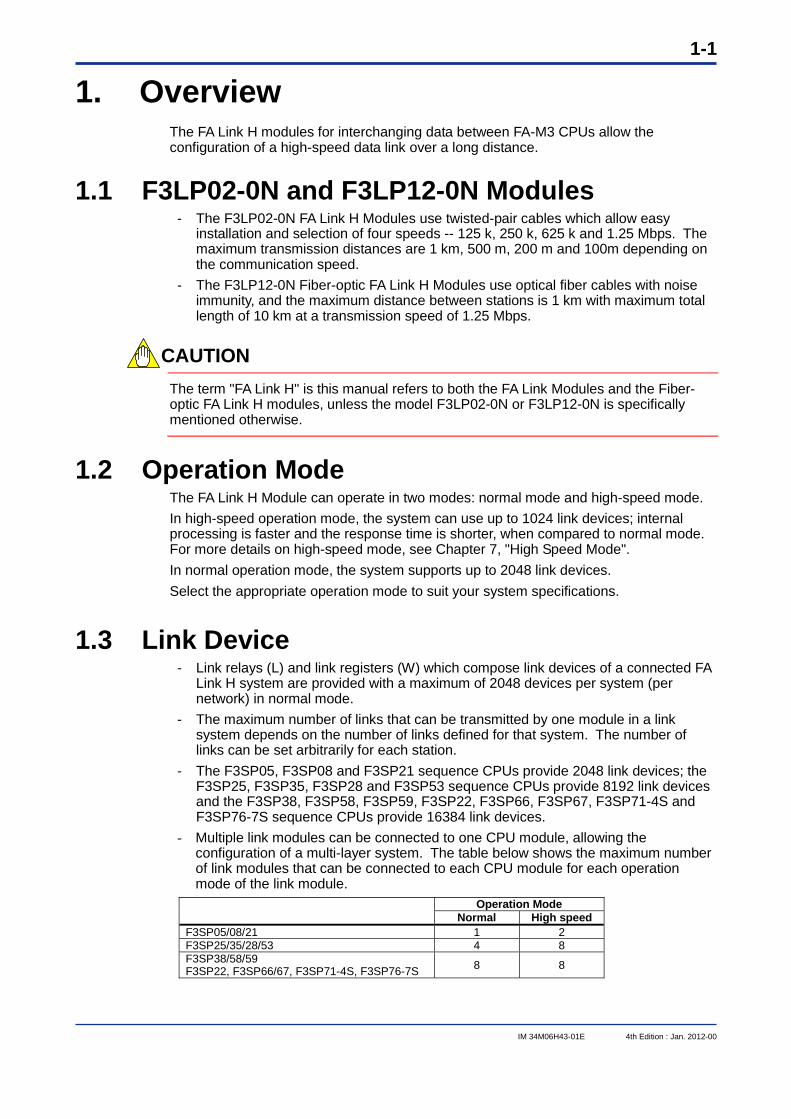
1. Overview The FA Link H modules for interchanging data between FA-M3 CPUs allow the configuration of a high-speed data link over a long distance.
1.1 F3LP02-0N and F3LP12-0N Modules - The F3LP02-0N FA Link H Modules use twisted-pair cables which allow easy
installation and selection of four speeds -- 125 k, 250 k, 625 k and 1.25 Mbps. The maximum transmission distances are 1 km, 500 m, 200 m and 100m depending on the communication speed.
- The F3LP12-0N Fiber-optic FA Link H Modules use optical fiber cables with noise immunity, and the maximum distance between stations is 1 km with maximum total length of 10 km at a transmission speed of 1.25 Mbps.
CAUTION
The term "FA Link H" is this manual refers to both the FA Link Modules and the Fiber-optic FA Link H modules, unless the model F3LP02-0N or F3LP12-0N is specifically mentioned otherwise.
1.2 Operation Mode The FA Link H Module can operate in two modes: normal mode and high-speed mode. In high-speed operation mode, the system can use up to 1024 link devices; internal processing is faster and the response time is shorter, when compared to normal mode. For more details on high-speed mode, see Chapter 7, "High Speed Mode". In normal operation mode, the system supports up to 2048 link devices. Select the appropriate operation mode to suit your system specifications.
1.3 Link Device - Link relays (L) and link registers (W) which compose link devices of a connected FA
Link H system are provided with a maximum of 2048 devices per system (per network) in normal mode.
- The maximum number of links that can be transmitted by one module in a link system depends on the number of links defined for that system. The number of links can be set arbitrarily for each station.
- The F3SP05, F3SP08 and F3SP21 sequence CPUs provide 2048 link devices; the F3SP25, F3SP35, F3SP28 and F3SP53 sequence CPUs provide 8192 link devices and the F3SP38, F3SP58, F3SP59, F3SP22, F3SP66, F3SP67, F3SP71-4S and F3SP76-7S sequence CPUs provide 16384 link devices.
- Multiple link modules can be connected to one CPU module, allowing the configuration of a multi-layer system. The table below shows the maximum number of link modules that can be connected to each CPU module for each operation mode of the link module.
Operation Mode Normal High speed
F3SP05/08/21 1 2 F3SP25/35/28/53 4 8 F3SP38/58/59 F3SP22, F3SP66/67, F3SP71-4S, F3SP76-7S 8 8
1-2
IM 34M06H43-01E 4th Edition : Jan. 2012-00
1.4 System Configuration This section shows the system configurations that can be constructed using the FA-Link H Modules.
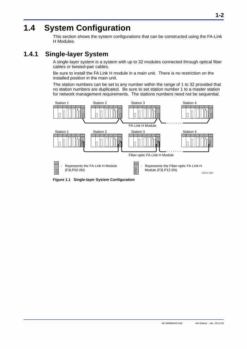
1.4.1 Single-layer System A single-layer system is a system with up to 32 modules connected through optical fiber cables or twisted-pair cables. Be sure to install the FA Link H module in a main unit. There is no restriction on the installed position in the main unit. The station numbers can be set to any number within the range of 1 to 32 provided that no station numbers are duplicated. Be sure to set station number 1 to a master station for network management requirements. The stations numbers need not be sequential.
Station 1 Station 2 Station 3 Station 4
Station 1 Station 2 Station 3 Station 4
: Represents the FA Link H Module (F3LP02-0N)
: Represents the Fiber-optic FA Link H Module (F3LP12-0N)
F0141.VSD
FA Link H Module
Fiber-optic FA Link H Module
Figure 1.1 Single-layer System Configuration
1-3
IM 34M06H43-01E 4th Edition : Jan. 2012-00
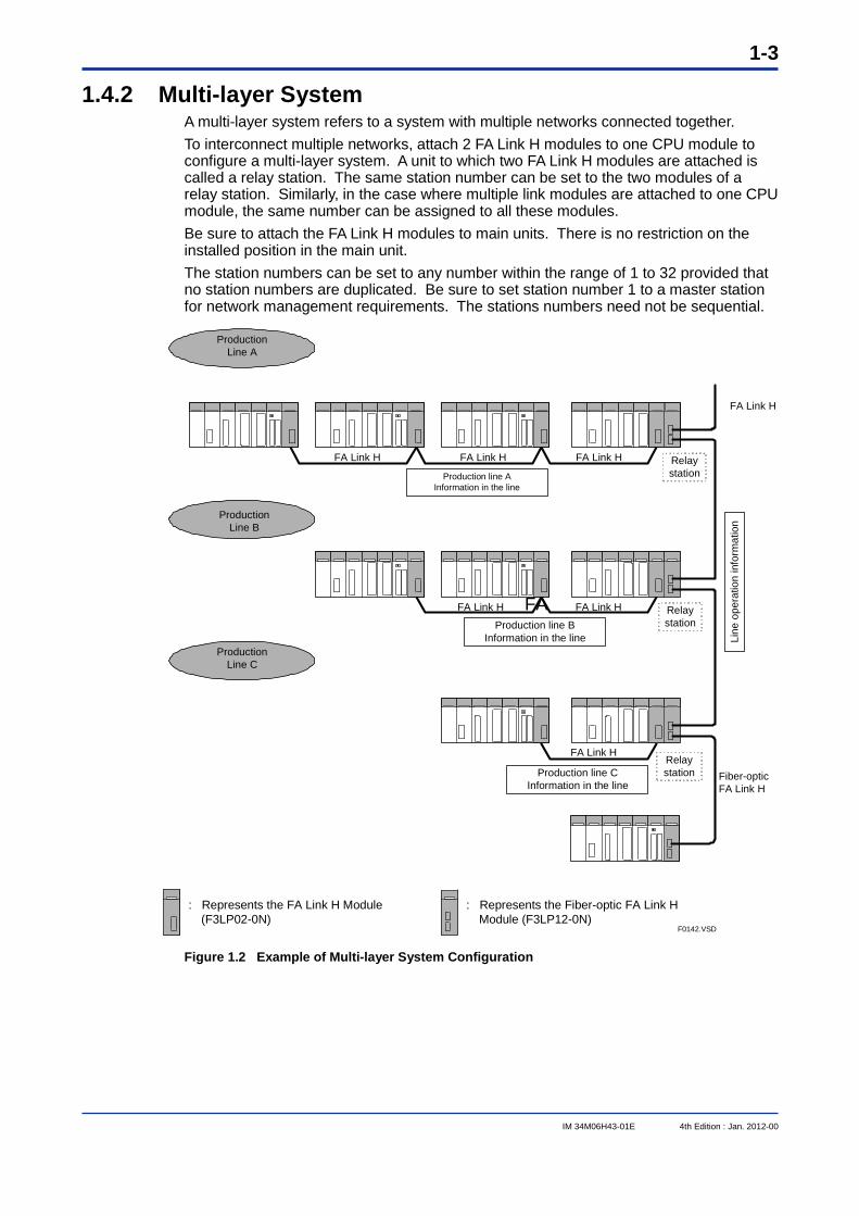
1.4.2 Multi-layer System A multi-layer system refers to a system with multiple networks connected together. To interconnect multiple networks, attach 2 FA Link H modules to one CPU module to configure a multi-layer system. A unit to which two FA Link H modules are attached is called a relay station. The same station number can be set to the two modules of a relay station. Similarly, in the case where multiple link modules are attached to one CPU module, the same number can be assigned to all these modules. Be sure to attach the FA Link H modules to main units. There is no restriction on the installed position in the main unit. The station numbers can be set to any number within the range of 1 to 32 provided that no station numbers are duplicated. Be sure to set station number 1 to a master station for network management requirements. The stations numbers need not be sequential.
FA Link H FA Link H FA Link H
Fiber-optic FA Link H
Production Line A
Production Line B
Production Line C
Production line A Information in the line
Relay station
FA Link H FA Link HFA Production line B
Information in the line
Relay station
Relay station
FA Link H
: Represents the FA Link H Module (F3LP02-0N)
: Represents the Fiber-optic FA Link H Module (F3LP12-0N)
F0142.VSD
Line
ope
ratio
n in
form
atio
n
FA Link H
Production line C Information in the line
Figure 1.2 Example of Multi-layer System Configuration
1-4
IM 34M06H43-01E 4th Edition : Jan. 2012-00
1.5 RAS Function - The link status can be checked using special relays or registers. - The F3LP02-0N module uses a bus-type communication configuration which allows
all operating stations in a network to continue linking even in the event that a link module in the network, other than the master station, is down due to power failure or other reasons. In addition, a station, which becomes unlinked due to a power failure or a temporary communication failure, will revert to linked status automatically once its condition is restored to normal.
- The F3LP02-0N module provides local loop-back functions to monitor the network status.
CAUTION
If any station in a network using F3LP12-0N modules is down due to power off or fiber-optic cable discontinuity, data linking of the entire network will fail.
IM 34M06H43-01E 4th Edition : Jan. 2012-00
2-1
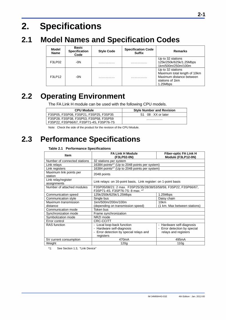
2. Specifications 2.1 Model Names and Specification Codes
Model Name
Basic Specification
Code Style Code Specification Code
Suffix Remarks
F3LP02 -0N …………… …………… Up to 32 stations 125k/250k/625k/1.25Mbps 1km/500m/250m/100m
F3LP12 -0N …………… ……………
Up to 32 stations Maximum total length of 10km Maximum distance between stations of 1km 1.25Mbps
2.2 Operating Environment The FA Link H module can be used with the following CPU models.
CPU Module Style Number and Revision F3SP05, F3SP08, F3SP21, F3SP25, F3SP35 S1 08 : XX or later F3SP28, F3SP38, F3SP53, F3SP58, F3SP59 F3SP22, F3SP66/67, F3SP71-4S, F3SP76-7S
……………
Note: Check the side of the product for the revision of the CPU Module.
2.3 Performance Specifications Table 2.1 Performance Specifications
Item FA Link H Module (F3LP02-0N)
Fiber-optic FA Link H Module (F3LP12-0N)
Number of connected stations 32 stations per system Link relays 16384 points*1 (Up to 2048 points per system) Link registers 16384 points*1 (Up to 2048 points per system) Maximum link points per station 2048 points
Link relay/register assignments Link relays: on 16-point basis, Link register: on 1-point basis
Number of attached modules F3SP05/08/21: 2 max. F3SP25/35/28/38/53/58/59, F3SP22, F3SP66/67, F3SP71-4S, F3SP76-7S: 8 max. *1
Communication speed 125k/250k/625k/1.25Mbps 1.25Mbps Communication style Single bus Daisy chain Maximum transmission distance
1km/500m/200m/100m (depending on transmission speed)
10km (1 km. Max between stations)
Communication mode Token bus Synchronization mode Frame synchronization Symbolization mode NRZI mode Error control CRC-CCITT RAS function - Local loop-back function
- Hardware self-diagnosis - Error detection by special relays and
registers
- Hardware self-diagnosis - Error detection by special
relays and registers
5V current consumption 470mA 495mA Weight 120g 110g
*1: See Section 1.3, "Link Device"
IM 34M06H43-01E 4th Edition : Jan. 2012-00
2-2
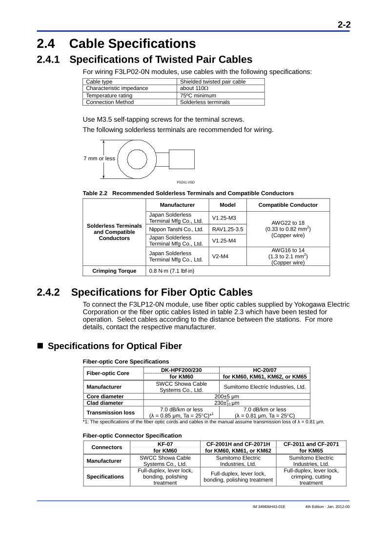
2.4 Cable Specifications 2.4.1 Specifications of Twisted Pair Cables
For wiring F3LP02-0N modules, use cables with the following specifications: Cable type Shielded twisted pair cable Characteristic impedance about 110 Temperature rating 75ºC minimum Connection Method Solderless terminals
Use M3.5 self-tapping screws for the terminal screws. The following solderless terminals are recommended for wiring.
7 mm or less
F0241.VSD Table 2.2 Recommended Solderless Terminals and Compatible Conductors
Manufacturer Model Compatible Conductor
Japan Solderless Terminal Mfg Co., Ltd. V1.25-M3
Nippon Tanshi Co., Ltd. RAV1.25-3.5 Japan Solderless Terminal Mfg Co., Ltd. V1.25-M4
AWG22 to 18 (0.33 to 0.82 mm2)
(Copper wire)
Solderless Terminals and Compatible
Conductors
Japan Solderless Terminal Mfg Co., Ltd. V2-M4
AWG16 to 14 (1.3 to 2.1 mm2) (Copper wire)
Crimping Torque 0.8 Nm (7.1 lbfin)
2.4.2 Specifications for Fiber Optic Cables To connect the F3LP12-0N module, use fiber optic cables supplied by Yokogawa Electric Corporation or the fiber optic cables listed in table 2.3 which have been tested for operation. Select cables according to the distance between the stations. For more details, contact the respective manufacturer.
Specifications for Optical Fiber Fiber-optic Core Specifications
DK-HPF200/230 HC-20/07 Fiber-optic Core for KM60 for KM60, KM61, KM62, or KM65
Manufacturer SWCC Showa Cable Systems Co., Ltd. Sumitomo Electric Industries, Ltd.
Core diameter 200±5 μm Clad diameter 230±0
10 μm
Transmission loss 7.0 dB/km or less (λ = 0.85 μm, Ta = 25C)*1
7.0 dB/km or less (λ = 0.81 μm, Ta = 25C)
*1: The specifications of the fiber optic cords and cables in the manual assume transmission loss of λ = 0.81 μm.
Fiber-optic Connector Specification KF-07 CF-2001H and CF-2071H CF-2011 and CF-2071 Connectors for KM60 for KM60, KM61, or KM62 for KM65
Manufacturer SWCC Showa Cable Systems Co., Ltd.
Sumitomo Electric Industries, Ltd.
Sumitomo Electric Industries, Ltd.
Specifications Full-duplex, lever lock,
bonding, polishing treatment
Full-duplex, lever lock, bonding, polishing treatment
Full-duplex, lever lock, crimping, cutting
treatment
IM 34M06H43-01E 4th Edition : Jan. 2012-00
2-3
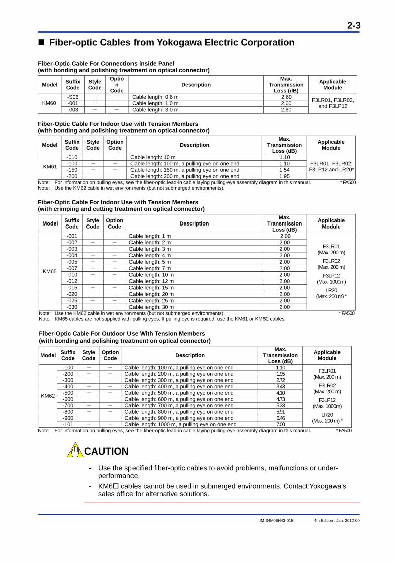
Fiber-optic Cables from Yokogawa Electric Corporation
Fiber-Optic Cable For Connections inside Panel (with bonding and polishing treatment on optical connector)
Model Suffix Code
Style Code
Option
Code Description
Max. Transmission
Loss (dB) Applicable
Module
-S06 - - Cable length: 0.6 m 2.60 -001 - - Cable length: 1.0 m 2.60 KM60 -003 - - Cable length: 3.0 m 2.60
F3LR01, F3LR02, and F3LP12
Fiber-Optic Cable For Indoor Use with Tension Members (with bonding and polishing treatment on optical connector)
Model Suffix Code
Style Code
Option Code Description
Max. Transmission
Loss (dB) Applicable
Module
-010 - - Cable length: 10 m 1.10 -100 - - Cable length: 100 m, a pulling eye on one end 1.10 -150 - - Cable length: 150 m, a pulling eye on one end 1.54 KM61
-200 - - Cable length: 200 m, a pulling eye on one end 1.95
F3LR01, F3LR02, F3LP12 and LR20*
Note: For information on pulling eyes, see the fiber-optic lead-in cable laying pulling-eye assembly diagram in this manual. * FA500 Note: Use the KM62 cable in wet environments (but not submerged environments).
Fiber-Optic Cable For Indoor Use with Tension Members (with crimping and cutting treatment on optical connector)
Model Suffix Code
Style Code
Option Code Description
Max. Transmission
Loss (dB) Applicable
Module
-001 - - Cable length: 1 m 2.00 -002 - - Cable length: 2 m 2.00 -003 - - Cable length: 3 m 2.00 -004 - - Cable length: 4 m 2.00 -005 - - Cable length: 5 m 2.00 -007 - - Cable length: 7 m 2.00 -010 - - Cable length: 10 m 2.00 -012 - - Cable length: 12 m 2.00 -015 - - Cable length: 15 m 2.00 -020 - - Cable length: 20 m 2.00 -025 - - Cable length: 25 m 2.00
KM65
-030 - - Cable length: 30 m 2.00
F3LR01 (Max. 200 m)
F3LR02 (Max. 200 m)
F3LP12 (Max. 1000m)
LR20 (Max. 200 m) *
Note: Use the KM62 cable in wet environments (but not submerged environments). * FA500 Note: KM65 cables are not supplied with pulling eyes. If pulling eye is required, use the KM61 or KM62 cables. Fiber-Optic Cable For Outdoor Use With Tension Members (with bonding and polishing treatment on optical connector)
Model Suffix Code
Style Code
OptionCode Description
Max. Transmission
Loss (dB) Applicable
Module
-100 - - Cable length: 100 m, a pulling eye on one end 1.10 -200 - - Cable length: 200 m, a pulling eye on one end 1.95 -300 - - Cable length: 300 m, a pulling eye on one end 2.72 -400 - - Cable length: 400 m, a pulling eye on one end 3.43 -500 - - Cable length: 500 m, a pulling eye on one end 4.10 -600 - - Cable length: 600 m, a pulling eye on one end 4.73 -700 - - Cable length: 700 m, a pulling eye on one end 5.33 -800 - - Cable length: 800 m, a pulling eye on one end 5.91 -900 - - Cable length: 900 m, a pulling eye on one end 6.46
KM62
-L01 - - Cable length: 1000 m, a pulling eye on one end 7.00
F3LR01 (Max. 200 m)
F3LR02 (Max. 200 m)
F3LP12 (Max. 1000m)
LR20 (Max. 200 m) *
Note: For information on pulling eyes, see the fiber-optic lead-in cable laying pulling-eye assembly diagram in this manual. * FA500
CAUTION
- Use the specified fiber-optic cables to avoid problems, malfunctions or under-performance.
- KM6 cables cannot be used in submerged environments. Contact Yokogawa’s sales office for alternative solutions.
IM 34M06H43-01E 4th Edition : Jan. 2012-00
2-4
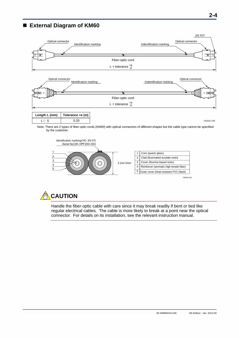
External Diagram of KM60
Length L (mm)
L 5
Tolerance +e (m)
0.20
Optical connectorIdentification marking
Optical connectorIndentification marking
Optical connectorIdentification marking
Optical connectorIndentification marking
Fiber-optic cord
Fiber-optic cord
+e -0
F02042.VSD
JIS F07
L + tolerance
+e -0L + tolerance
Note: There are 2 types of fiber-optic cords (KM60) with optical connectors of different shapes but the cable type cannot be specified
by the customer.
FB0243.VSD
2.2±0.3mm
12345
Identification marking(HC- 20/07)Serial No(DK- HPF200/230)
1
2
3
4
5
Core (quartz glass)
Clad (fluorinated acrylate resin)
Cover (fluorine-based resin)
Reinforcer (aromatic high tensile fiber)
Outer cover (heat-resistant PVC black)
CAUTION
Handle the fiber-optic cable with care since it may break readily if bent or tied like regular electrical cables. The cable is more likely to break at a point near the optical connector. For details on its installation, see the relevant instruction manual.
IM 34M06H43-01E 4th Edition : Jan. 2012-00
2-5
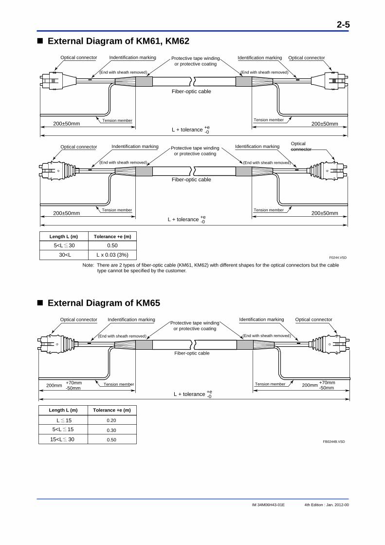
External Diagram of KM61, KM62
Length L (m)
5<L 30
30<L
Tolerance +e (m)
0.50
L x 0.03 (3%) F0244.VSD
Optical connector Indentification marking Optical connectorIdentification marking
Fiber-optic cable
Tension member Tension member
Protective tape winding or protective coating
(End with sheath removed)(End with sheath removed)
200±50mm 200±50mm
Optical connector Indentification marking Optical connectorIdentification marking
Fiber-optic cable
Tension member Tension member
Protective tape winding or protective coating
(End with sheath removed)(End with sheath removed)
200±50mm 200±50mm+e -0L + tolerance
+e -0L + tolerance
Note: There are 2 types of fiber-optic cable (KM61, KM62) with different shapes for the optical connectors but the cable
type cannot be specified by the customer.
External Diagram of KM65
0.30
0.50
FB0244B.VSD
Optical connector Indentification marking
Fiber-optic cable
Protective tape winding or protective coating
(End with sheath removed)
200mm +70mm-50mm 200mm +70mm
-50mm
0.20
Optical connectorIdentification marking
(End with sheath removed)
Tension member
+e -0L + tolerance
Tension member
Length L (m) Tolerance +e (m)
15<L 30
5<L 15 L 15
IM 34M06H43-01E 4th Edition : Jan. 2012-00
2-6
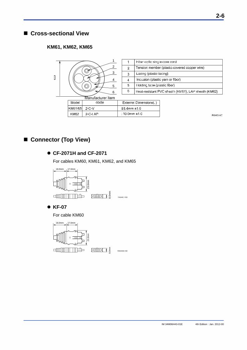
Cross-sectional View
KM61, KM62, KM65
1
2
3
4
5
6
Connector (Top View)
CF-2071H and CF-2071 For cables KM60, KM61, KM62, and KM65
FA0445. VSD
23.0
mm
18.0mm 17.0mm
8.0m
m
KF-07 For cable KM60
FB0245B.VSD
23.0
mm
18.0mm 17.0mm
8.0m
m
IM 34M06H43-01E 4th Edition : Jan. 2012-00
2-7
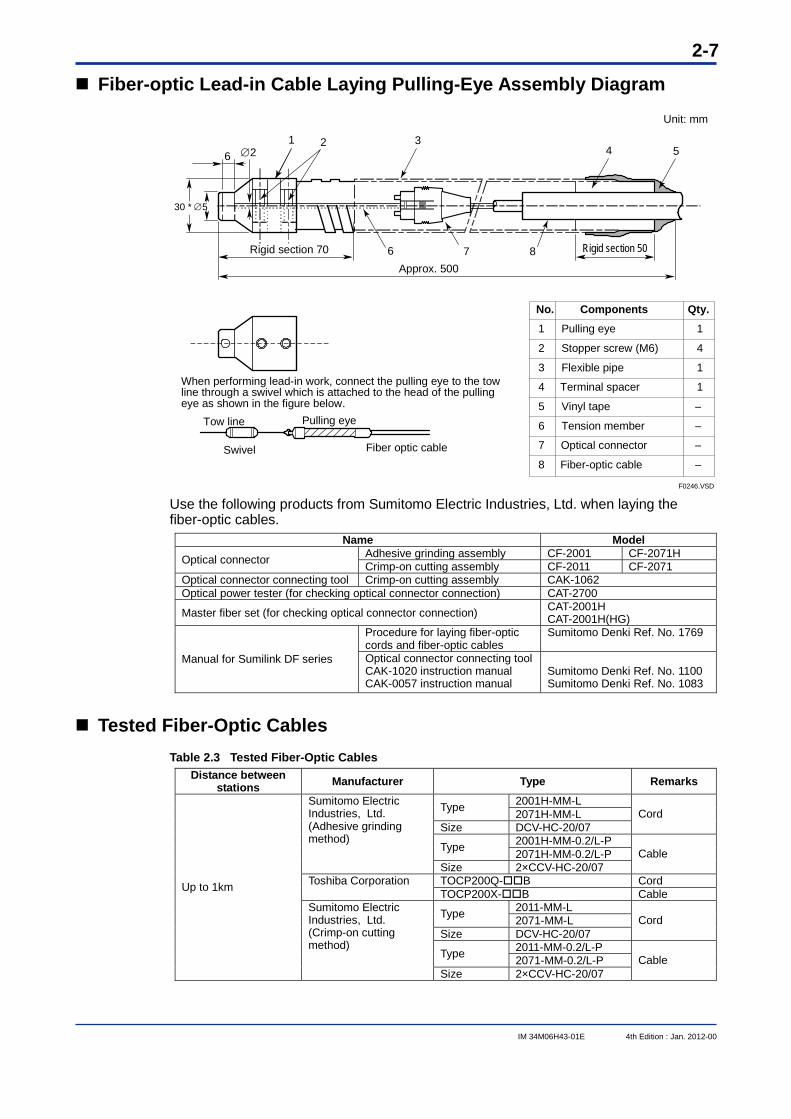
Fiber-optic Lead-in Cable Laying Pulling-Eye Assembly Diagram
6 2
30 * 5
Rigid section 70
Approx. 500
Rigid section 50
Unit: mm
1 3
6 7 8
4 52
No.
1
2
3
4
5
6
7
8
Qty.
1
4
1
1
Components
Pulling eye
Stopper screw (M6)
Flexible pipe
Terminal spacer
Vinyl tape
Tension member
Optical connector
Fiber-optic cable
When performing lead-in work, connect the pulling eye to the tow line through a swivel which is attached to the head of the pulling eye as shown in the figure below.
Tow line
Swivel
Pulling eye
Fiber optic cable
F0246.VSD Use the following products from Sumitomo Electric Industries, Ltd. when laying the fiber-optic cables.
Name Model Adhesive grinding assembly CF-2001 CF-2071H Optical connector Crimp-on cutting assembly CF-2011 CF-2071
Optical connector connecting tool Crimp-on cutting assembly CAK-1062 Optical power tester (for checking optical connector connection) CAT-2700
Master fiber set (for checking optical connector connection) CAT-2001H CAT-2001H(HG)
Procedure for laying fiber-optic cords and fiber-optic cables
Sumitomo Denki Ref. No. 1769
Manual for Sumilink DF series Optical connector connecting tool CAK-1020 instruction manual CAK-0057 instruction manual
Sumitomo Denki Ref. No. 1100 Sumitomo Denki Ref. No. 1083
Tested Fiber-Optic Cables Table 2.3 Tested Fiber-Optic Cables
Distance between stations Manufacturer Type Remarks
2001H-MM-L Type 2071H-MM-L Size DCV-HC-20/07
Cord
2001H-MM-0.2/L-P Type 2071H-MM-0.2/L-P
Sumitomo Electric Industries, Ltd. (Adhesive grinding method)
Size 2×CCV-HC-20/07 Cable
TOCP200Q-B Cord Toshiba Corporation TOCP200X-B Cable
2011-MM-L Type 2071-MM-L Size DCV-HC-20/07
Cord
2011-MM-0.2/L-P Type 2071-MM-0.2/L-P
Up to 1km
Sumitomo Electric Industries, Ltd. (Crimp-on cutting method)
Size 2×CCV-HC-20/07 Cable
IM 34M06H43-01E 4th Edition : Jan. 2012-00
2-8
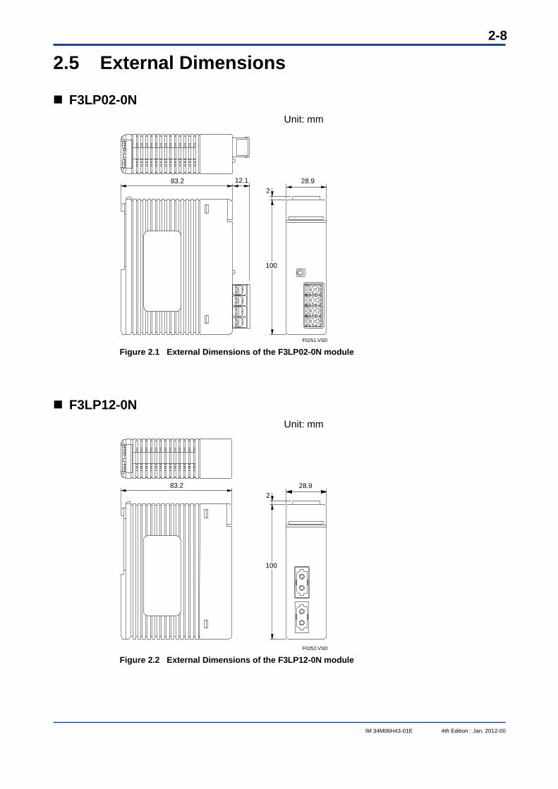
2.5 External Dimensions
F3LP02-0N Unit: mm
83.2 28.92
12.1
F0251.VSD
100
Figure 2.1 External Dimensions of the F3LP02-0N module
F3LP12-0N Unit: mm
28.92
83.2
100
F0252.VSD Figure 2.2 External Dimensions of the F3LP12-0N module
3-1
IM 34M06H43-01E 4th Edition : Jan. 2012-00
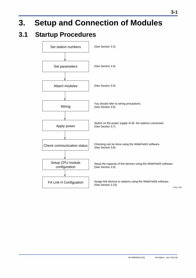
3. Setup and Connection of Modules 3.1 Startup Procedures
(See Section 3.3)
(See Section 3.4)
(See Section 3.5)
You should refer to wiring precautions.(See Section 3.6)
Switch on the power supply of all the stations connected.(See Section 3.7)
Checking can be done using the WideField3 software.(See Section 3.8).
Setup the capacity of link devices using the WideField3 software.(See Section 3.9)
Assign link devices to stations using the WideField3 software.(See Section 3.10)
Setup CPU module configuration
FA Link H ConfiguationF0311.VSD
Check communication status
Apply power
Wiring
Attach modules
Set parameters
Set station numbers
3-2
IM 34M06H43-01E 4th Edition : Jan. 2012-00
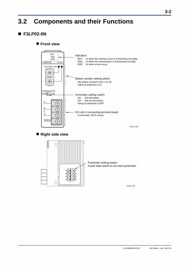
3.2 Components and their Functions
F3LP02-0N
Front view
RDY SND
ERR
IndicatorsRDY: Lit when the internal circuit is functioning mormallySND: Lit when the transmission is functioning normallyERR: Lit when errors occur.
Station number setting switch:Set station numbers from 1 to 32.Value at shipment is 01
STATION NO.
TERMINATOROFF ON Terminator setting switch:
On: Set terminator.Off: Not set terminator.Setup at shipment is OFF
(4 terminals, M3.5 screw)FA Link H connecting terminal board
B
A
SG
SHIELD
01
2 3 45
6
7890
1
2 3 45
6
789
FA LINKLP02-0N
F0321.VSD
Right side view
F0322.VSD
Parameter setting switch:4-pole slide switch to set each parameter.
1
2
3
OFF
4
3-3
IM 34M06H43-01E 4th Edition : Jan. 2012-00
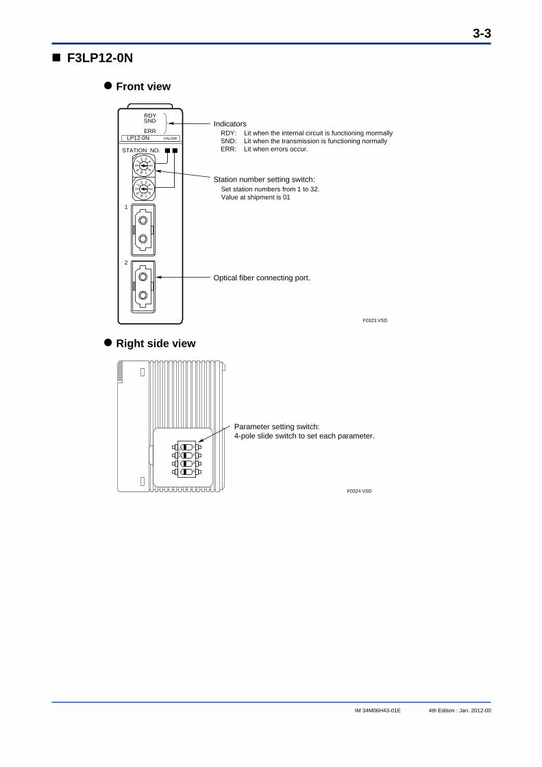
F3LP12-0N
Front view
RDYSND
ERR
STATION NO.
1
2
Optical fiber connecting port.
FALINKLP12-0N0
1
2 3 45
6
7890
1
2 3 45
6
789
F0323.VSD
IndicatorsRDY: Lit when the internal circuit is functioning mormallySND: Lit when the transmission is functioning normallyERR: Lit when errors occur.
Station number setting switch:Set station numbers from 1 to 32.Value at shipment is 01
Right side view
F0324.VSD
Parameter setting switch:4-pole slide switch to set each parameter.
1
2
3
OFF
4
3-4
IM 34M06H43-01E 4th Edition : Jan. 2012-00
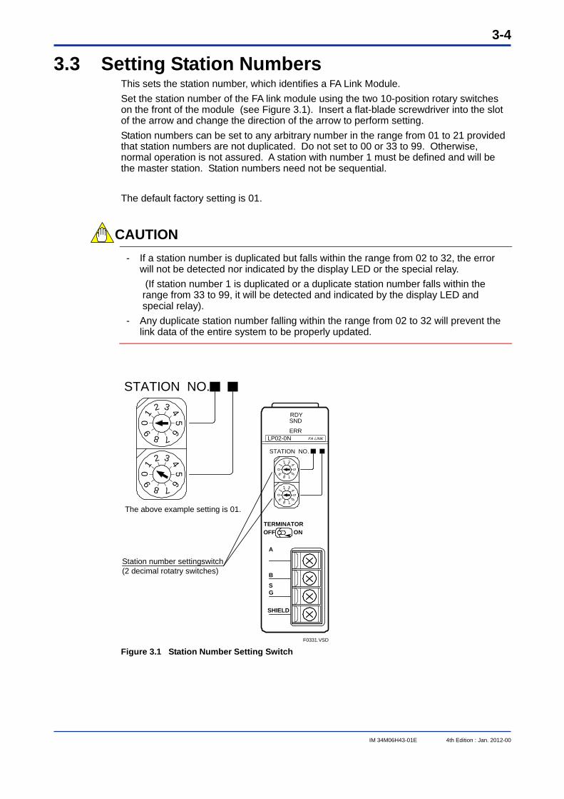
3.3 Setting Station Numbers This sets the station number, which identifies a FA Link Module. Set the station number of the FA link module using the two 10-position rotary switches on the front of the module (see Figure 3.1). Insert a flat-blade screwdriver into the slot of the arrow and change the direction of the arrow to perform setting. Station numbers can be set to any arbitrary number in the range from 01 to 21 provided that station numbers are not duplicated. Do not set to 00 or 33 to 99. Otherwise, normal operation is not assured. A station with number 1 must be defined and will be the master station. Station numbers need not be sequential. The default factory setting is 01.
CAUTION
- If a station number is duplicated but falls within the range from 02 to 32, the error will not be detected nor indicated by the display LED or the special relay. (If station number 1 is duplicated or a duplicate station number falls within the range from 33 to 99, it will be detected and indicated by the display LED and special relay).
- Any duplicate station number falling within the range from 02 to 32 will prevent the link data of the entire system to be properly updated.
RDY SND
ERR
STATION NO.
TERMINATOROFF ON
B
A
SG
SHIELD
01
2 3 45
6
7890
1
2 3 45
6
789
FA LINKLP02-0N
STATION NO.
01
2 3 45
6
7890
1
2 3 45
6
789
F0331.VSD
The above example setting is 01.
Station number settingswitch(2 decimal rotatry switches)
Figure 3.1 Station Number Setting Switch
3-5
IM 34M06H43-01E 4th Edition : Jan. 2012-00
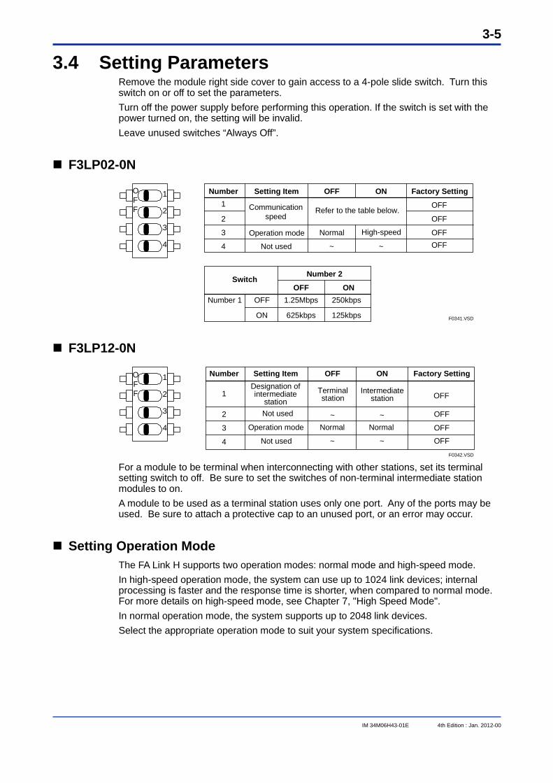
3.4 Setting Parameters Remove the module right side cover to gain access to a 4-pole slide switch. Turn this switch on or off to set the parameters. Turn off the power supply before performing this operation. If the switch is set with the power turned on, the setting will be invalid. Leave unused switches “Always Off”.
F3LP02-0N
1
2
3
4
F0341.VSD
OFF
Number Setting Item
OFF
ON Factory Setting
OFF ONSwitch
Number 1
1
2
3
4 Not used
Normal High-speed
OFF
OFFOFF~
OFF
Number 2
OFF
ON
1.25Mbps 250kbps
125kbps625kbps
Communication speed
Refer to the table below.
Operation mode
~
F3LP12-0N
1
2
3
4
F0342.VSD
OFF
Number Setting Item
OFF
ON Factory Setting
1
2
3
4
Operation mode
Not used
Normal Normal
OFF
OFF
OFF~
OFFDesignation of intermediate
stationNot used
Terminalstation
Intermediate station
~
~~
For a module to be terminal when interconnecting with other stations, set its terminal setting switch to off. Be sure to set the switches of non-terminal intermediate station modules to on. A module to be used as a terminal station uses only one port. Any of the ports may be used. Be sure to attach a protective cap to an unused port, or an error may occur.
Setting Operation Mode The FA Link H supports two operation modes: normal mode and high-speed mode. In high-speed operation mode, the system can use up to 1024 link devices; internal processing is faster and the response time is shorter, when compared to normal mode. For more details on high-speed mode, see Chapter 7, "High Speed Mode". In normal operation mode, the system supports up to 2048 link devices. Select the appropriate operation mode to suit your system specifications.
3-6
IM 34M06H43-01E 4th Edition : Jan. 2012-00
3.5 Attaching and Detaching Modules Attaching the Module
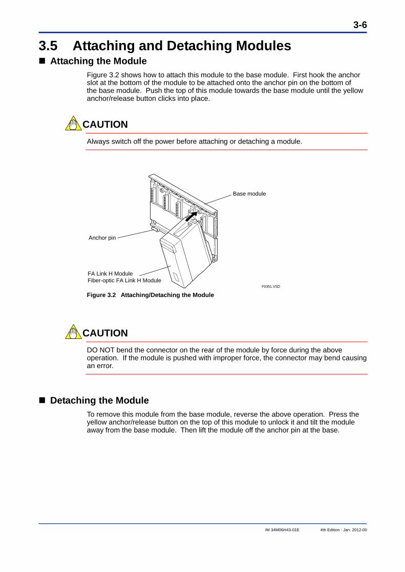
Figure 3.2 shows how to attach this module to the base module. First hook the anchor slot at the bottom of the module to be attached onto the anchor pin on the bottom of the base module. Push the top of this module towards the base module until the yellow anchor/release button clicks into place.
CAUTION
Always switch off the power before attaching or detaching a module.
F0351.VSD
Base module
FA Link H ModuleFiber-optic FA Link H Module
Anchor pin
Figure 3.2 Attaching/Detaching the Module
CAUTION
DO NOT bend the connector on the rear of the module by force during the above operation. If the module is pushed with improper force, the connector may bend causing an error.
Detaching the Module To remove this module from the base module, reverse the above operation. Press the yellow anchor/release button on the top of this module to unlock it and tilt the module away from the base module. Then lift the module off the anchor pin at the base.
3-7
IM 34M06H43-01E 4th Edition : Jan. 2012-00
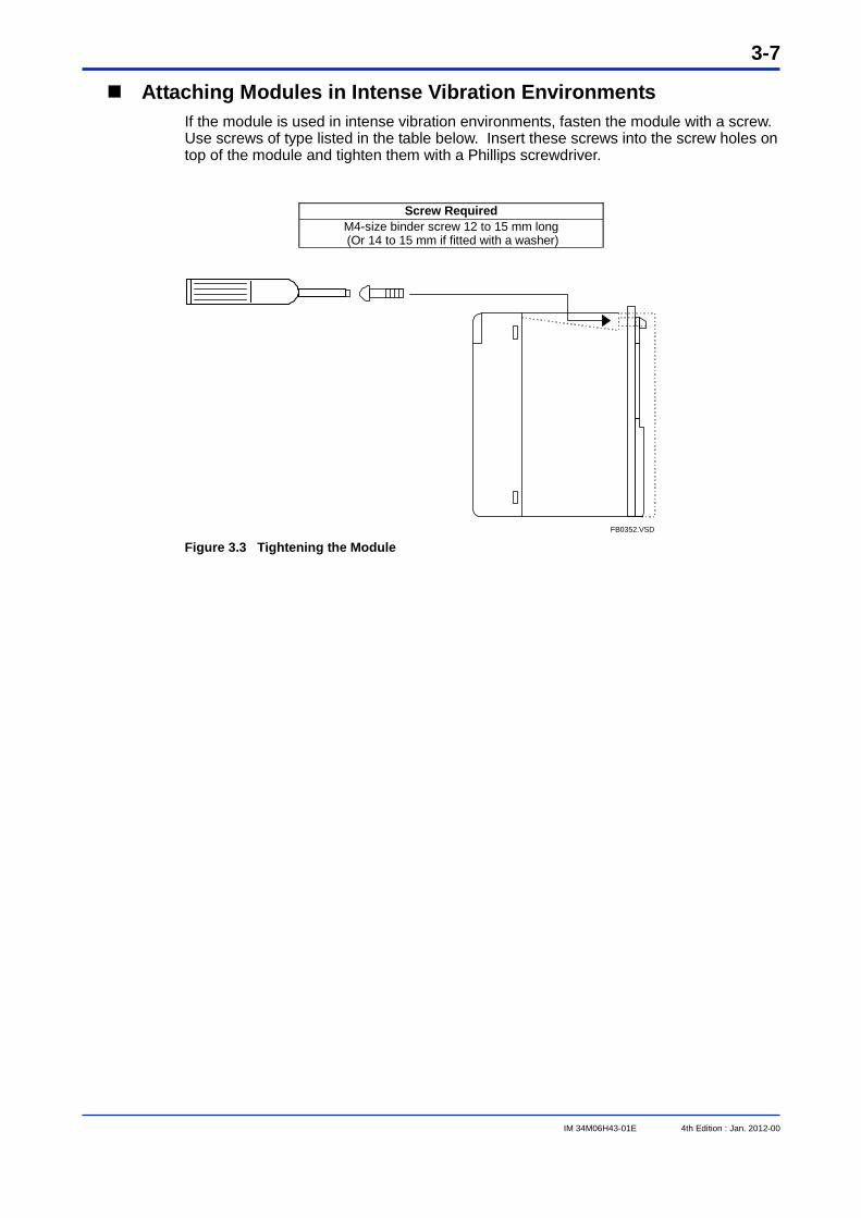
Attaching Modules in Intense Vibration Environments If the module is used in intense vibration environments, fasten the module with a screw. Use screws of type listed in the table below. Insert these screws into the screw holes on top of the module and tighten them with a Phillips screwdriver.
Screw Required M4-size binder screw 12 to 15 mm long
(Or 14 to 15 mm if fitted with a washer)
FB0352.VSD Figure 3.3 Tightening the Module
3-8
IM 34M06H43-01E 4th Edition : Jan. 2012-00
3.6 Wiring This section describes the wiring of the FA Link H Modules.
F3LP02-0N
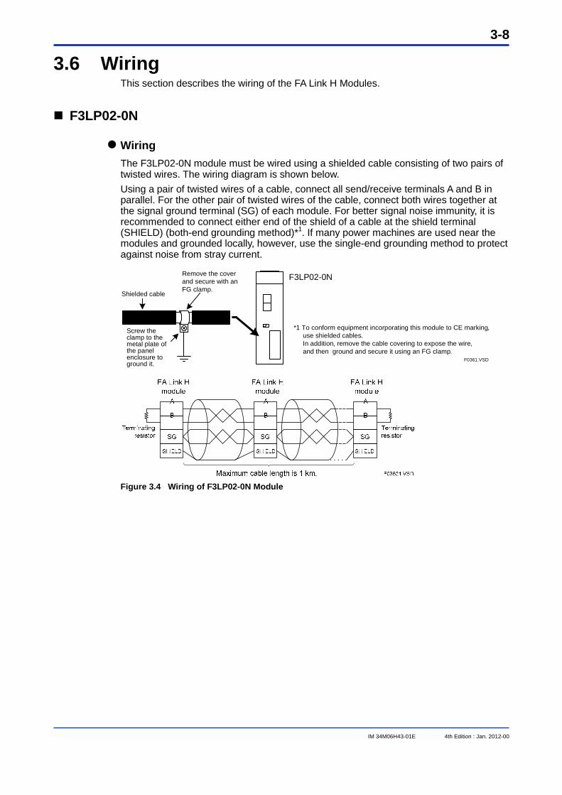
Wiring The F3LP02-0N module must be wired using a shielded cable consisting of two pairs of twisted wires. The wiring diagram is shown below. Using a pair of twisted wires of a cable, connect all send/receive terminals A and B in parallel. For the other pair of twisted wires of the cable, connect both wires together at the signal ground terminal (SG) of each module. For better signal noise immunity, it is recommended to connect either end of the shield of a cable at the shield terminal (SHIELD) (both-end grounding method)*1. If many power machines are used near the modules and grounded locally, however, use the single-end grounding method to protect against noise from stray current.
F3LP02-0NRemove the cover and secure with an FG clamp.
Shielded cable
Screw the clamp to the metal plate of the panel enclosure to ground it.
F0361.VSD
*1 To conform equipment incorporating this module to CE marking, use shielded cables. In addition, remove the cable covering to expose the wire, and then ground and secure it using an FG clamp.
Figure 3.4 Wiring of F3LP02-0N Module
3-9
IM 34M06H43-01E 4th Edition : Jan. 2012-00
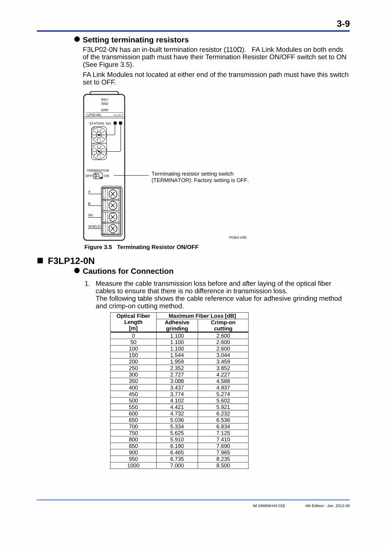
Setting terminating resistors F3LP02-0N has an in-built termination resistor (110Ω). FA Link Modules on both ends of the transmission path must have their Termination Resister ON/OFF switch set to ON (See Figure 3.5). FA Link Modules not located at either end of the transmission path must have this switch set to OFF.
Terminating resistor setting switch (TERMINATOR): Factory setting is OFF.
F0363.VSD
RDY SND ERR
STATION NO.
TERMINATOROFF ON
B
A
SG
SHIELD
01 2 3 4
56
7890
1
2 3 45
6
789
FA LINKLP02-0N
Figure 3.5 Terminating Resistor ON/OFF
F3LP12-0N Cautions for Connection
1. Measure the cable transmission loss before and after laying of the optical fiber cables to ensure that there is no difference in transmission loss. The following table shows the cable reference value for adhesive grinding method and crimp-on cutting method.
Maximum Fiber Loss [dB] Optical Fiber Length
[m] Adhesive grinding
Crimp-on cutting
0 1.100 2.600 50 1.100 2.600
100 1.100 2.600 150 1.544 3.044 200 1.959 3.459 250 2.352 3.852 300 2.727 4.227 350 3.088 4.588 400 3.437 4.937 450 3.774 5.274 500 4.102 5.602 550 4.421 5.921 600 4.732 6.232 650 5.036 6.536 700 5.334 6.834 750 5.625 7.125 800 5.910 7.410 850 6.190 7.690 900 6.465 7.965 950 6.735 8.235
1000 7.000 8.500
3-10
IM 34M06H43-01E 4th Edition : Jan. 2012-00
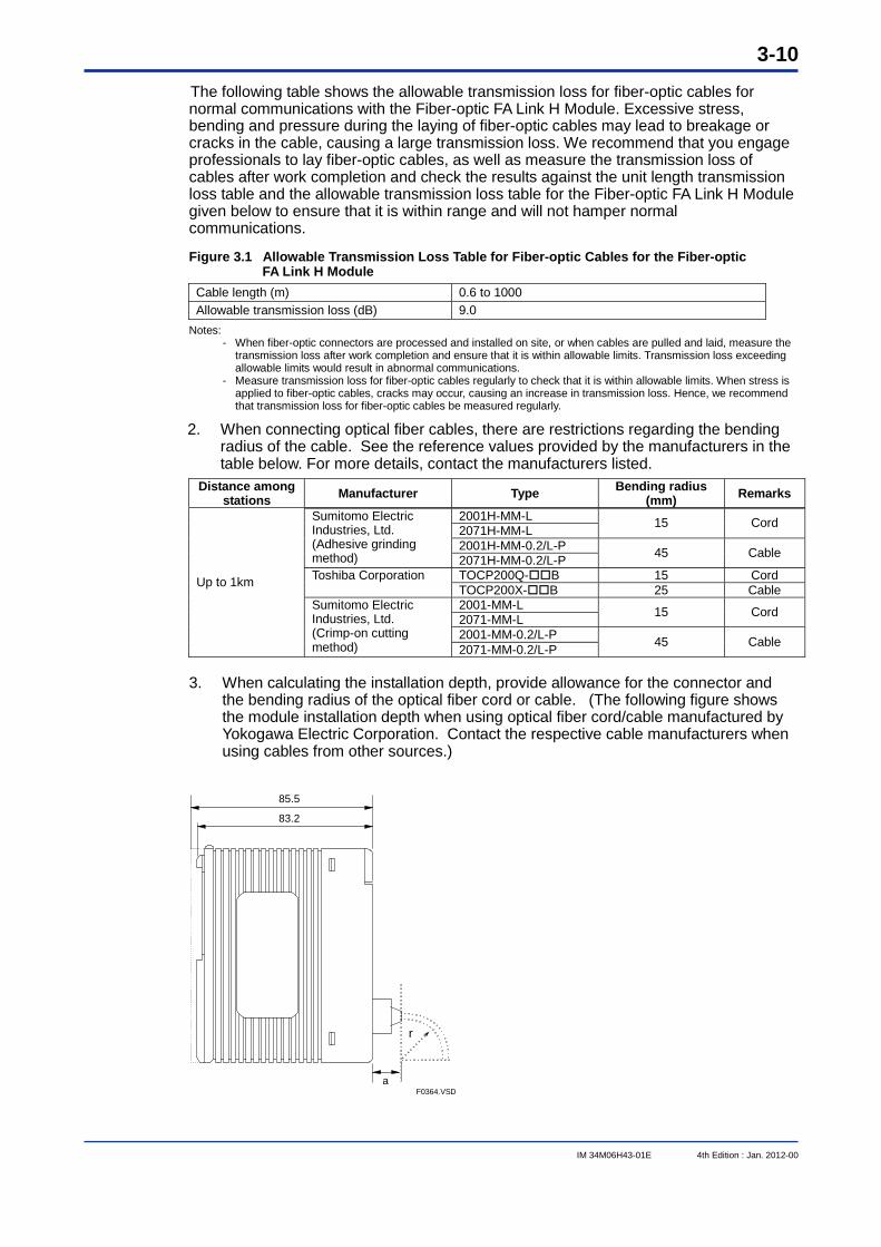
The following table shows the allowable transmission loss for fiber-optic cables for normal communications with the Fiber-optic FA Link H Module. Excessive stress, bending and pressure during the laying of fiber-optic cables may lead to breakage or cracks in the cable, causing a large transmission loss. We recommend that you engage professionals to lay fiber-optic cables, as well as measure the transmission loss of cables after work completion and check the results against the unit length transmission loss table and the allowable transmission loss table for the Fiber-optic FA Link H Module given below to ensure that it is within range and will not hamper normal communications.
Figure 3.1 Allowable Transmission Loss Table for Fiber-optic Cables for the Fiber-optic FA Link H Module
Cable length (m) 0.6 to 1000 Allowable transmission loss (dB) 9.0
Notes: - When fiber-optic connectors are processed and installed on site, or when cables are pulled and laid, measure the
transmission loss after work completion and ensure that it is within allowable limits. Transmission loss exceeding allowable limits would result in abnormal communications.
- Measure transmission loss for fiber-optic cables regularly to check that it is within allowable limits. When stress is applied to fiber-optic cables, cracks may occur, causing an increase in transmission loss. Hence, we recommend that transmission loss for fiber-optic cables be measured regularly.
2. When connecting optical fiber cables, there are restrictions regarding the bending radius of the cable. See the reference values provided by the manufacturers in the table below. For more details, contact the manufacturers listed.
Distance among stations Manufacturer Type Bending radius
(mm) Remarks
2001H-MM-L 2071H-MM-L 15 Cord
2001H-MM-0.2/L-P
Sumitomo Electric Industries, Ltd. (Adhesive grinding method) 2071H-MM-0.2/L-P 45 Cable
TOCP200Q-B 15 Cord Toshiba Corporation TOCP200X-B 25 Cable 2001-MM-L 2071-MM-L 15 Cord
2001-MM-0.2/L-P
Up to 1km
Sumitomo Electric Industries, Ltd. (Crimp-on cutting method) 2071-MM-0.2/L-P 45 Cable
3. When calculating the installation depth, provide allowance for the connector and
the bending radius of the optical fiber cord or cable. (The following figure shows the module installation depth when using optical fiber cord/cable manufactured by Yokogawa Electric Corporation. Contact the respective cable manufacturers when using cables from other sources.)
r
83.2
85.5
aF0364.VSD
3-11
IM 34M06H43-01E 4th Edition : Jan. 2012-00
4. While installing the fiber optic cables, do not touch the core at the cable ends and
ensure that it is free from dust. 5. When inserting fiber optic cables into their connectors, do not reverse the direction
of the cables. Each time the cables are attached or detached from the ports, hold the optical connector.
6. Attach protective caps to ports, which are not in use.
CAUTION We recommend that you engage professionals to lay the optical fiber cables.
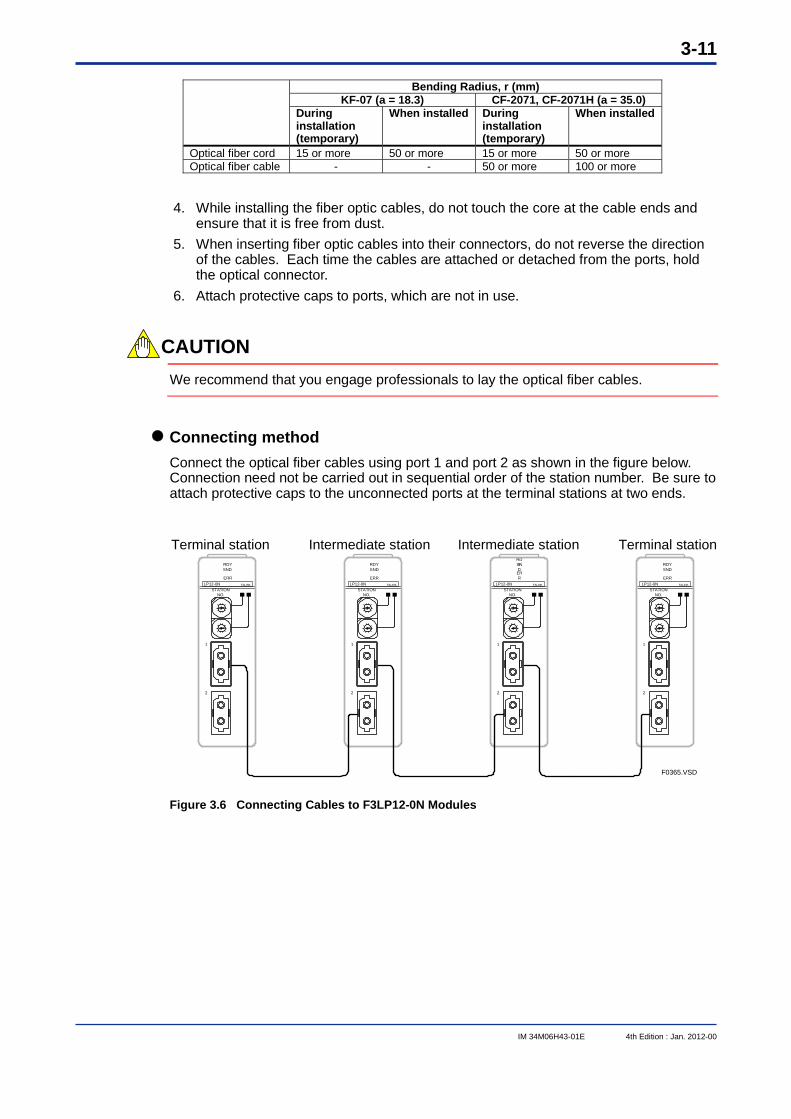
Connecting method Connect the optical fiber cables using port 1 and port 2 as shown in the figure below. Connection need not be carried out in sequential order of the station number. Be sure to attach protective caps to the unconnected ports at the terminal stations at two ends.
RDYSND
ERR
STATION NO.
1
2
FALINKLP12-0N
RDYSND
ERR
STATION NO.
1
2
FALINKLP12-0N
RDYSNDERR
STATION NO.
1
2
FALINKLP12-0N
RDYSND
ERR
STATION NO.
1
2
FALINKLP12-0N
F0365.VSD
Terminal station Terminal stationIntermediate stationIntermediate station
Figure 3.6 Connecting Cables to F3LP12-0N Modules
Bending Radius, r (mm) KF-07 (a = 18.3) CF-2071, CF-2071H (a = 35.0)
During installation (temporary)
When installed During installation (temporary)
When installed
Optical fiber cord 15 or more 50 or more 15 or more 50 or more Optical fiber cable - - 50 or more 100 or more

3-12
IM 34M06H43-01E 4th Edition : Jan. 2012-00
3.7 Applying the Power
F3LP02-0N Power can be applied in any order, regardless of the master station and slave stations.
F3LP12-0N First apply power to all the slave stations. Then apply power to the master station.
CAUTION If any of the stations in a network of F3LP12-0N modules are turned off, data link in the entire network cannot proceed. For a network of F3LP02-0N modules, even if some stations are turned off, data links continues among the stations, which are turned on, provided that the master station is turned on.
3-13
IM 34M06H43-01E 4th Edition : Jan. 2012-00
3.8 Checking Communication Status The communication status of the FA Link H module can be checked using a personal computer and the WideField3 software package, which can be procured separately from Yokogawa. Connect the personal computer to the programming port of the CPU module in any station using a special-purpose cable for the programming tool and start WideField3. You can check the communication status on the FA Link Status Monitor window. This section explains how to operate the FA Link Status Monitor. For details on the WideField3 software, read the FA-M3 Programming Tool WideField3 User’s Manuals (IM34M06Q16-01E, -02E, -03E, and -04E), which can be procured separately from Yokogawa.
TIP If you are using WideField2, you may read “WideField3” as “WideField2” in this manual.
For details, read the FA-M3 Programming Tool WideField2 User’s Manual (IM34M06Q15-01E), which can be procured separately from Yokogawa.
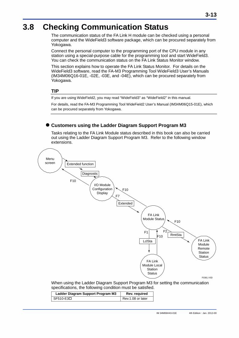
Customers using the Ladder Diagram Support Program M3 Tasks relating to the FA Link Module status described in this book can also be carried out using the Ladder Diagram Support Program M3. Refer to the following window extensions.
Extended function
Diagnostic
Extended
F0381.VSD
Menu screen
FA Link Module Status
F10
F10
F7
I/O Module Configuration
Display
F10
F10F2F1
FA Link Module Local
Station Status
FA Link Module Remote Station Status
RmtSta
LclSta
When using the Ladder Diagram Support Program M3 for setting the communication specifications, the following condition must be satisfied.
Ladder Diagram Support Program M3 Rev. required SF510-E3 Rev.1.08 or later
3-14
IM 34M06H43-01E 4th Edition : Jan. 2012-00
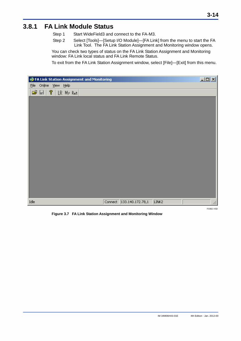
3.8.1 FA Link Module Status Step 1 Start WideField3 and connect to the FA-M3. Step 2 Select [Tools]―[Setup I/O Module]―[FA Link] from the menu to start the FA
Link Tool. The FA Link Station Assignment and Monitoring window opens. You can check two types of status on the FA Link Station Assignment and Monitoring window: FA Link local status and FA Link Remote Status. To exit from the FA Link Station Assignment window, select [File]―[Exit] from this menu.
F0382.VSD Figure 3.7 FA Link Station Assignment and Monitoring Window
3-15
IM 34M06H43-01E 4th Edition : Jan. 2012-00
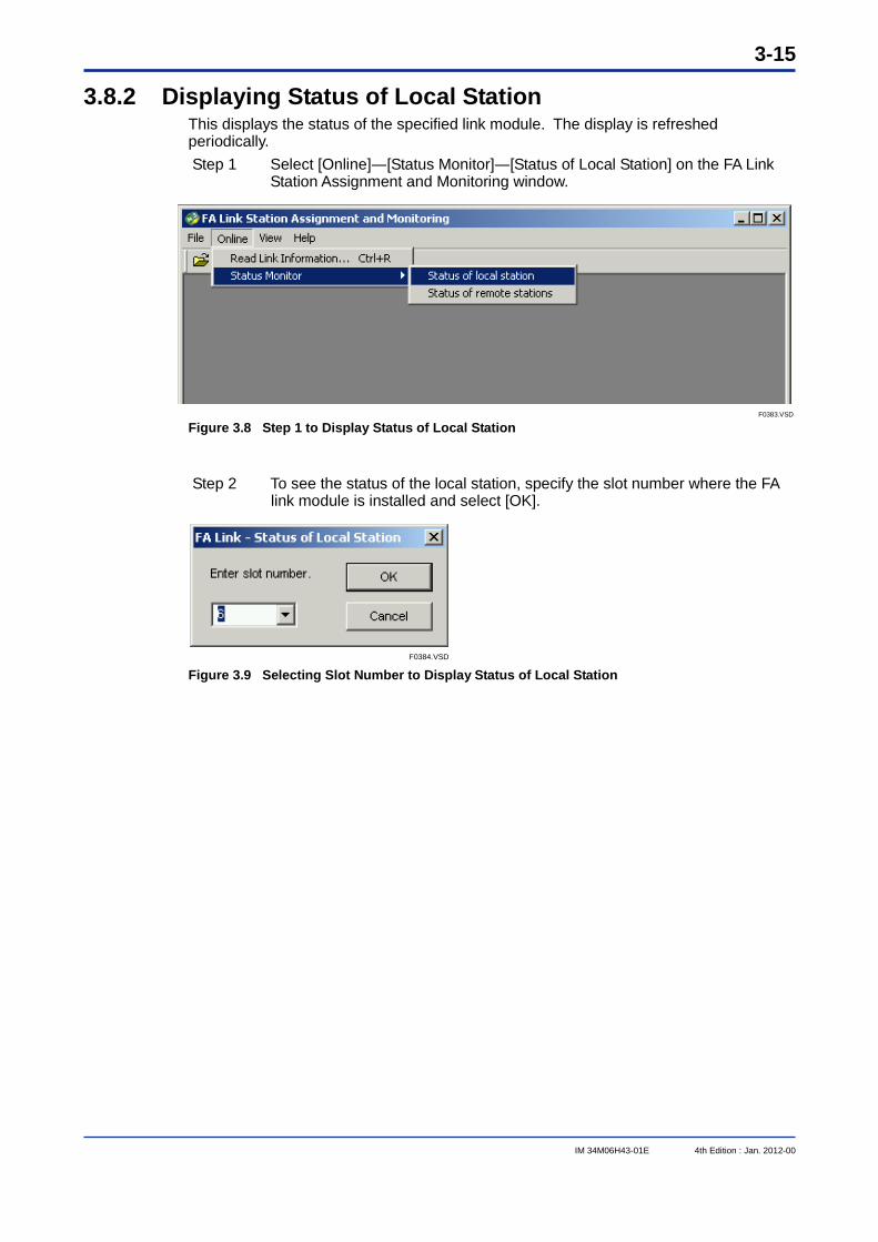
3.8.2 Displaying Status of Local Station This displays the status of the specified link module. The display is refreshed periodically. Step 1 Select [Online]―[Status Monitor]―[Status of Local Station] on the FA Link
Station Assignment and Monitoring window.
F0383.VSD Figure 3.8 Step 1 to Display Status of Local Station
Step 2 To see the status of the local station, specify the slot number where the FA
link module is installed and select [OK].
F0384.VSD Figure 3.9 Selecting Slot Number to Display Status of Local Station
3-16
IM 34M06H43-01E 4th Edition : Jan. 2012-00
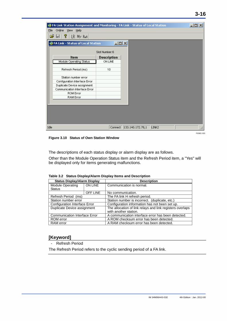
F0385.VSD Figure 3.10 Status of Own Station Window
The descriptions of each status display or alarm display are as follows. Other than the Module Operation Status item and the Refresh Period item, a "Yes" will be displayed only for items generating malfunctions.
Table 3.2 Status Display/Alarm Display Items and Description Status Display/Alarm Display Description
Module Operating Status
ON LINE Communication is normal.
OFF LINE No communication. Refresh Period (ms) The FA link H refresh period. Station number error Station number is incorrect. (duplicate, etc.) Configuration Interface Error Configuration information has not been set up. Duplicate Device assignment The allocation of link relays and link registers overlaps
with another station. Communication Interface Error A communication interface error has been detected. ROM error A ROM checksum error has been detected. RAM error A RAM checksum error has been detected.
[Keyword] - Refresh Period
The Refresh Period refers to the cyclic sending period of a FA link.
3-17
IM 34M06H43-01E 4th Edition : Jan. 2012-00
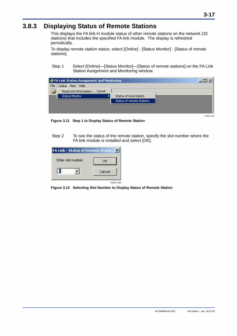
3.8.3 Displaying Status of Remote Stations This displays the FA link H module status of other remote stations on the network (32 stations) that includes the specified FA link module. The display is refreshed periodically. To display remote station status, select [Online] - [Status Monitor] - [Status of remote stations].
Step 1 Select [Online]―[Status Monitor]―[Status of remote stations] on the FA Link Station Assignment and Monitoring window.
F0386.VSD Figure 3.11 Step 1 to Display Status of Remote Station
Step 2 To see the status of the remote station, specify the slot number where the FA link module is installed and select [OK].
F0387.VSD Figure 3.12 Selecting Slot Number to Display Status of Remote Station
3-18
IM 34M06H43-01E 4th Edition : Jan. 2012-00
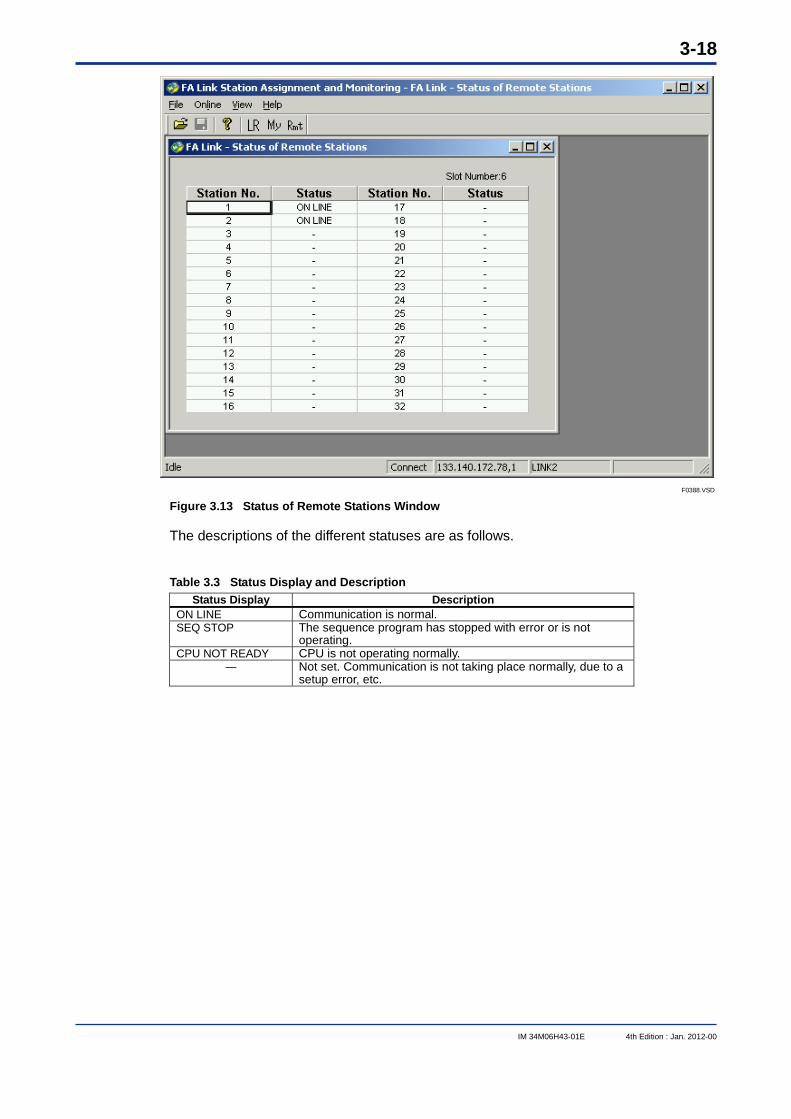
F0388.VSD Figure 3.13 Status of Remote Stations Window
The descriptions of the different statuses are as follows.
Table 3.3 Status Display and Description Status Display Description
ON LINE Communication is normal. SEQ STOP The sequence program has stopped with error or is not
operating. CPU NOT READY CPU is not operating normally.
― Not set. Communication is not taking place normally, due to a setup error, etc.
3-19
IM 34M06H43-01E 4th Edition : Jan. 2012-00
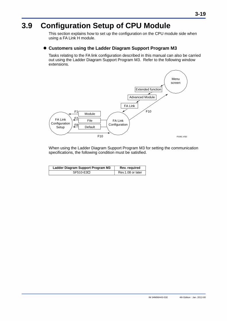
3.9 Configuration Setup of CPU Module This section explains how to set up the configuration on the CPU module side when using a FA Link H module.
Customers using the Ladder Diagram Support Program M3 Tasks relating to the FA link configuration described in this manual can also be carried out using the Ladder Diagram Support Program M3. Refer to the following window extensions.
Advanced Module
Extended function
Menu screen
FA Link Configuration
FA Link Configuration
Setup
Module
File
Default
FA Link
F10F1
F8
F2
F10 F0391.VSD When using the Ladder Diagram Support Program M3 for setting the communication specifications, the following condition must be satisfied.
Ladder Diagram Support Program M3 Rev. required SF510-E3 Rev.1.08 or later
3-20
IM 34M06H43-01E 4th Edition : Jan. 2012-00
3.9.1 Setting Device Capacities This setting is required when using an FA link H module. Setting values depend on whether the FA Link H module is used in high-speed mode or normal mode. Be sure to perform the setting according to the setting examples for the different CPU models shown in the following pages. This setting is performed on the project Configuration window.
3-21
IM 34M06H43-01E 4th Edition : Jan. 2012-00
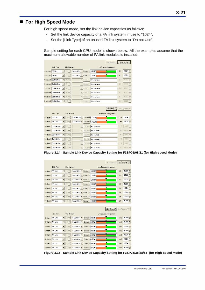
For High Speed Mode For high speed mode, set the link device capacities as follows: - Set the link device capacity of a FA link system in use to "1024". - Set the [Link Type] of an unused FA link system to "Do not Use".
Sample setting for each CPU model is shown below. All the examples assume that the maximum allowable number of FA link modules is installed.
Figure 3.14 Sample Link Device Capacity Setting for F3SP05/08/21 (for High-speed Mode)
Figure 3.15 Sample Link Device Capacity Setting for F3SP25/35/28/53 (for High-speed Mode)
3-22
IM 34M06H43-01E 4th Edition : Jan. 2012-00
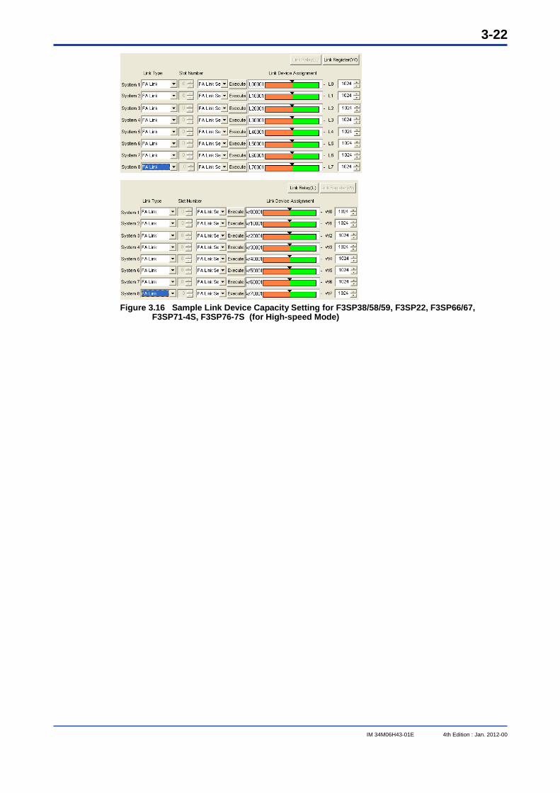
Figure 3.16 Sample Link Device Capacity Setting for F3SP38/58/59, F3SP22, F3SP66/67,
F3SP71-4S, F3SP76-7S (for High-speed Mode)
3-23
IM 34M06H43-01E 4th Edition : Jan. 2012-00
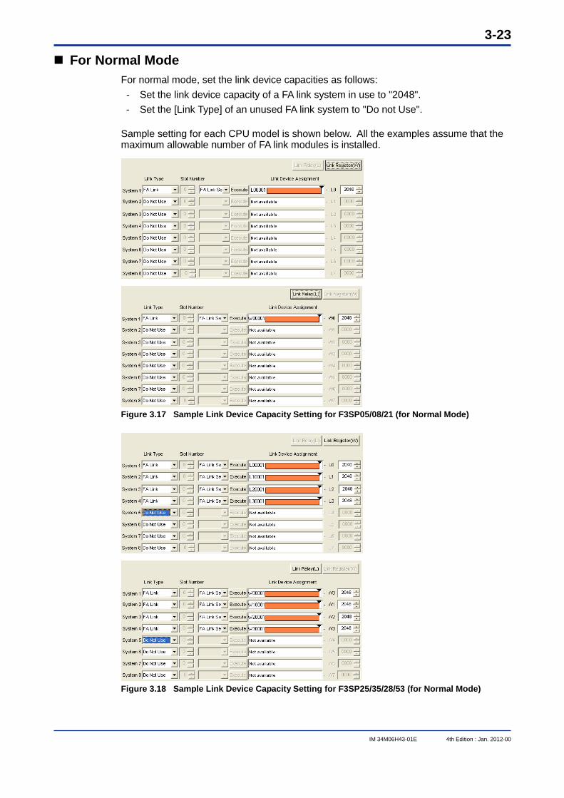
For Normal Mode For normal mode, set the link device capacities as follows: - Set the link device capacity of a FA link system in use to "2048". - Set the [Link Type] of an unused FA link system to "Do not Use".
Sample setting for each CPU model is shown below. All the examples assume that the maximum allowable number of FA link modules is installed.
Figure 3.17 Sample Link Device Capacity Setting for F3SP05/08/21 (for Normal Mode)
Figure 3.18 Sample Link Device Capacity Setting for F3SP25/35/28/53 (for Normal Mode)
3-24
IM 34M06H43-01E 4th Edition : Jan. 2012-00
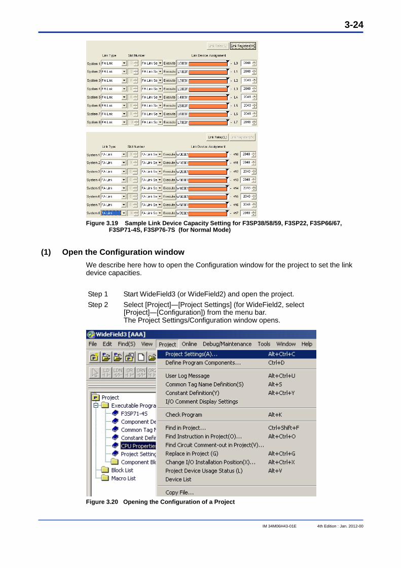
Figure 3.19 Sample Link Device Capacity Setting for F3SP38/58/59, F3SP22, F3SP66/67,
F3SP71-4S, F3SP76-7S (for Normal Mode)
(1) Open the Configuration window We describe here how to open the Configuration window for the project to set the link device capacities.
Step 1 Start WideField3 (or WideField2) and open the project. Step 2 Select [Project]―[Project Settings] (for WideField2, select
[Project]―[Configuration]) from the menu bar. The Project Settings/Configuration window opens.
Figure 3.20 Opening the Configuration of a Project
3-25
IM 34M06H43-01E 4th Edition : Jan. 2012-00
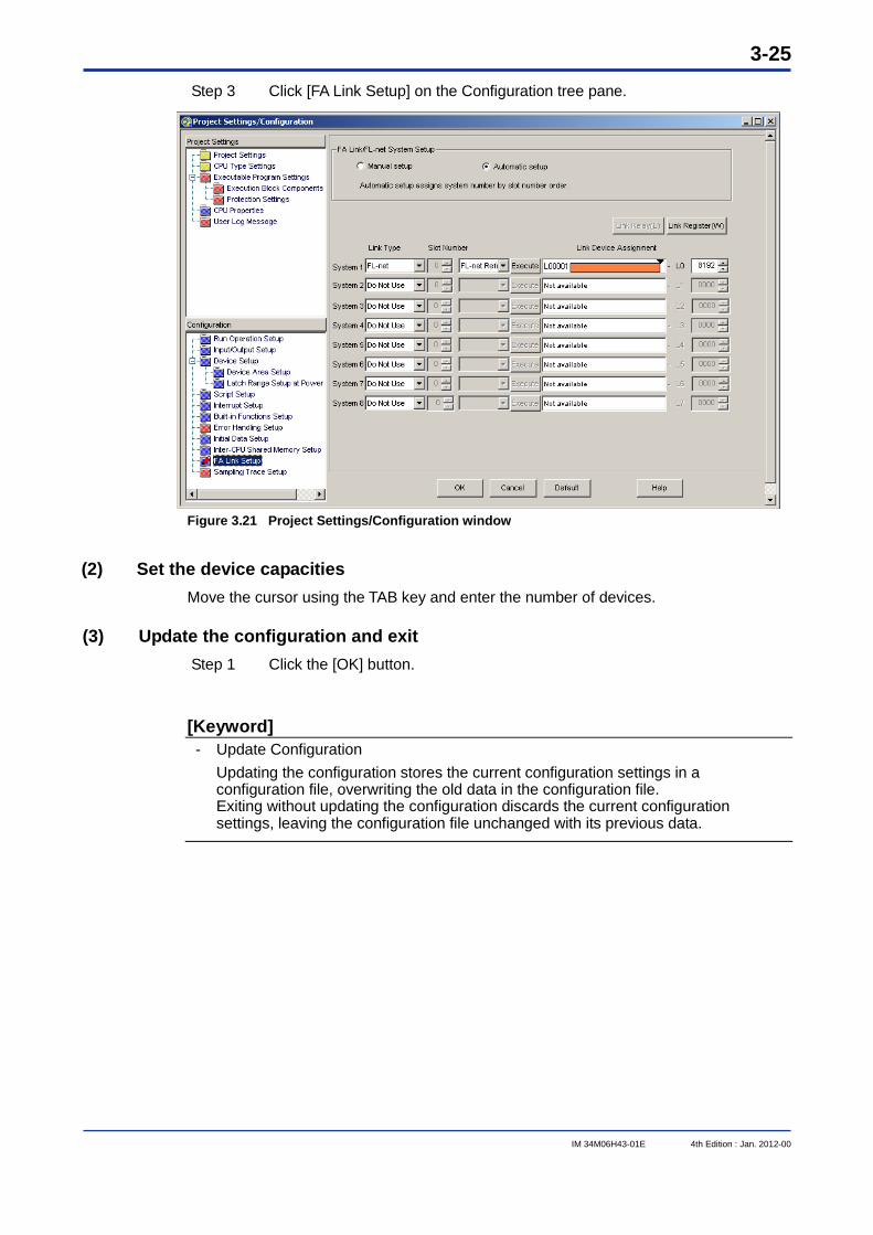
Step 3 Click [FA Link Setup] on the Configuration tree pane.
Figure 3.21 Project Settings/Configuration window
(2) Set the device capacities Move the cursor using the TAB key and enter the number of devices.
(3) Update the configuration and exit Step 1 Click the [OK] button.
[Keyword] - Update Configuration Updating the configuration stores the current configuration settings in a
configuration file, overwriting the old data in the configuration file. Exiting without updating the configuration discards the current configuration settings, leaving the configuration file unchanged with its previous data.
3-26
IM 34M06H43-01E 4th Edition : Jan. 2012-00
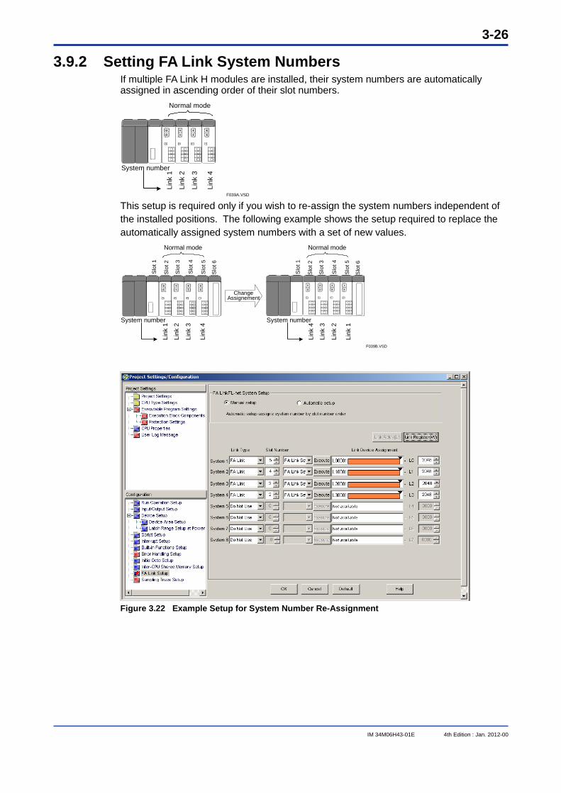
3.9.2 Setting FA Link System Numbers If multiple FA Link H modules are installed, their system numbers are automatically assigned in ascending order of their slot numbers.
System number
F039A.VSD
Link
4
Normal mode
Link
3
Link
2
Link
1
This setup is required only if you wish to re-assign the system numbers independent of the installed positions. The following example shows the setup required to replace the automatically assigned system numbers with a set of new values.
Change Assignement
F039B.VSD
Normal mode Normal mode
System number
Link
4
Link
3
Link
2
Link
1
System number
Link
1
Link
2
Link
3
Link
4
Slo
t 1
Slo
t 2
Slo
t 3
Slo
t 4
Slo
t 5
Slo
t 6
Slo
t 1
Slo
t 2
Slo
t 3
Slo
t 4
Slo
t 5
Slo
t 6
Figure 3.22 Example Setup for System Number Re-Assignment
3-27
IM 34M06H43-01E 4th Edition : Jan. 2012-00
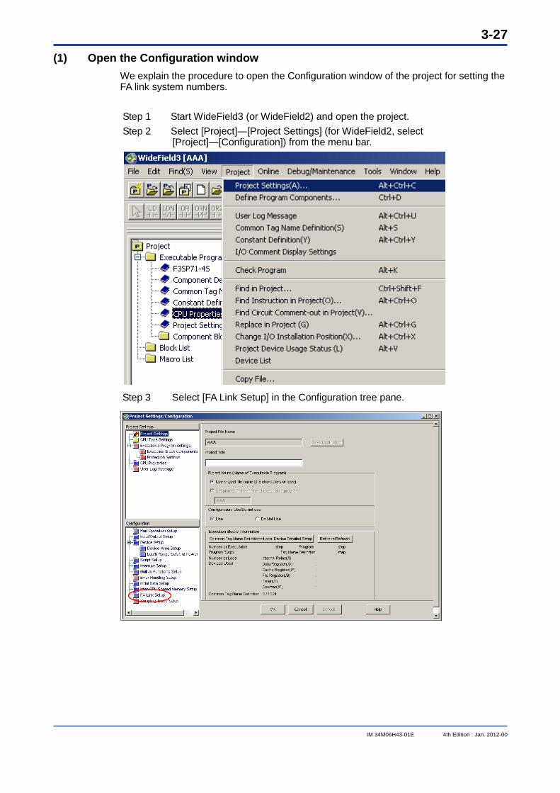
(1) Open the Configuration window We explain the procedure to open the Configuration window of the project for setting the FA link system numbers.
Step 1 Start WideField3 (or WideField2) and open the project. Step 2 Select [Project]―[Project Settings] (for WideField2, select
[Project]―[Configuration]) from the menu bar.
Step 3 Select [FA Link Setup] in the Configuration tree pane.
3-28
IM 34M06H43-01E 4th Edition : Jan. 2012-00
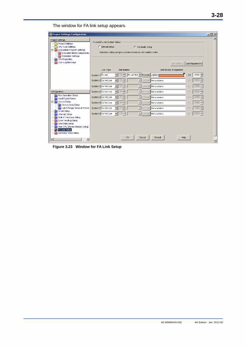
The window for FA link setup appears.
Figure 3.23 Window for FA Link Setup
3-29
IM 34M06H43-01E 4th Edition : Jan. 2012-00
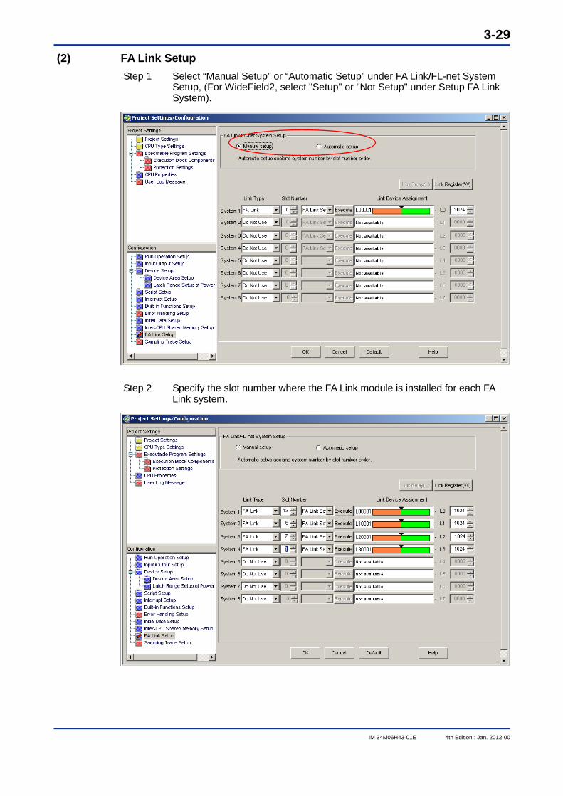
(2) FA Link Setup Step 1 Select “Manual Setup” or “Automatic Setup” under FA Link/FL-net System
Setup, (For WideField2, select "Setup" or "Not Setup" under Setup FA Link System).
Step 2 Specify the slot number where the FA Link module is installed for each FA
Link system.
3-30
IM 34M06H43-01E 4th Edition : Jan. 2012-00
(3) Update the configuration and exit Step 1 Click the [OK] button.
[Keyword] - Update Configuration Updating the configuration stores the current configuration settings in a configuration
file, over-writing the old data in the configuration file. Exiting without updating the configuration discards the current configuration settings, leaving the configuration file unchanged with its previous data.
3-31
IM 34M06H43-01E 4th Edition : Jan. 2012-00
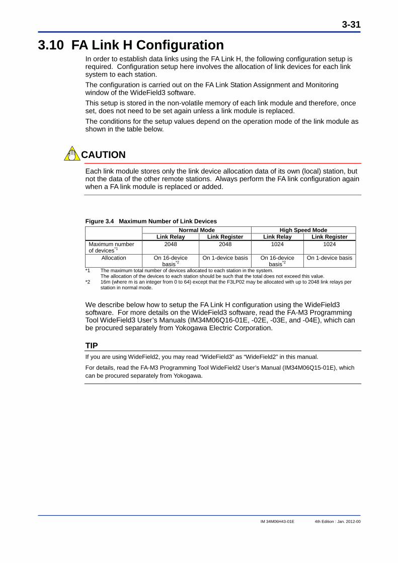
3.10 FA Link H Configuration In order to establish data links using the FA Link H, the following configuration setup is required. Configuration setup here involves the allocation of link devices for each link system to each station. The configuration is carried out on the FA Link Station Assignment and Monitoring window of the WideField3 software. This setup is stored in the non-volatile memory of each link module and therefore, once set, does not need to be set again unless a link module is replaced. The conditions for the setup values depend on the operation mode of the link module as shown in the table below.
CAUTION Each link module stores only the link device allocation data of its own (local) station, but not the data of the other remote stations. Always perform the FA link configuration again when a FA link module is replaced or added.
Figure 3.4 Maximum Number of Link Devices Normal Mode High Speed Mode
Link Relay Link Register Link Relay Link Register Maximum number of devices*1
2048 2048 1024 1024
Allocation On 16-device basis*2
On 1-device basis On 16-device basis*2
On 1-device basis
*1 The maximum total number of devices allocated to each station in the system. The allocation of the devices to each station should be such that the total does not exceed this value. *2 16m (where m is an integer from 0 to 64) except that the F3LP02 may be allocated with up to 2048 link relays per
station in normal mode. We describe below how to setup the FA Link H configuration using the WideField3 software. For more details on the WideField3 software, read the FA-M3 Programming Tool WideField3 User’s Manuals (IM34M06Q16-01E, -02E, -03E, and -04E), which can be procured separately from Yokogawa Electric Corporation.
TIP If you are using WideField2, you may read “WideField3” as “WideField2” in this manual.
For details, read the FA-M3 Programming Tool WideField2 User’s Manual (IM34M06Q15-01E), which can be procured separately from Yokogawa.
3-32
IM 34M06H43-01E 4th Edition : Jan. 2012-00
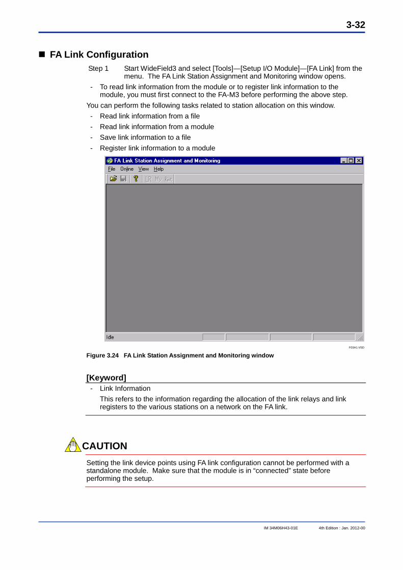
FA Link Configuration Step 1 Start WideField3 and select [Tools]―[Setup I/O Module]―[FA Link] from the
menu. The FA Link Station Assignment and Monitoring window opens. - To read link information from the module or to register link information to the
module, you must first connect to the FA-M3 before performing the above step. You can perform the following tasks related to station allocation on this window. - Read link information from a file - Read link information from a module - Save link information to a file - Register link information to a module
F03A1.VSD Figure 3.24 FA Link Station Assignment and Monitoring window
[Keyword] - Link Information This refers to the information regarding the allocation of the link relays and link
registers to the various stations on a network on the FA link.
CAUTION
Setting the link device points using FA link configuration cannot be performed with a standalone module. Make sure that the module is in “connected” state before performing the setup.
3-33
IM 34M06H43-01E 4th Edition : Jan. 2012-00
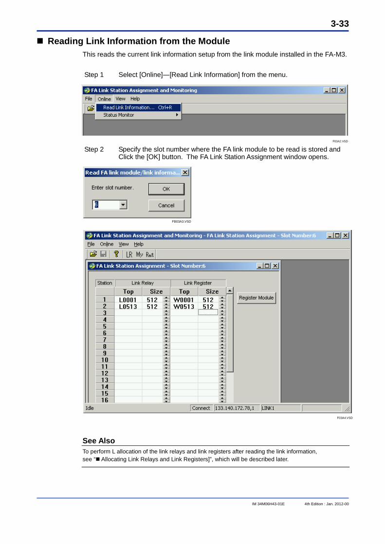
Reading Link Information from the Module This reads the current link information setup from the link module installed in the FA-M3.
Step 1 Select [Online]―[Read Link Information] from the menu.
F03A2.VSD Step 2 Specify the slot number where the FA link module to be read is stored and
Click the [OK] button. The FA Link Station Assignment window opens.
FB03A3.VSD
F03A4.VSD
See Also To perform L allocation of the link relays and link registers after reading the link information, see “ Allocating Link Relays and Link Registers]”, which will be described later.
3-34
IM 34M06H43-01E 4th Edition : Jan. 2012-00
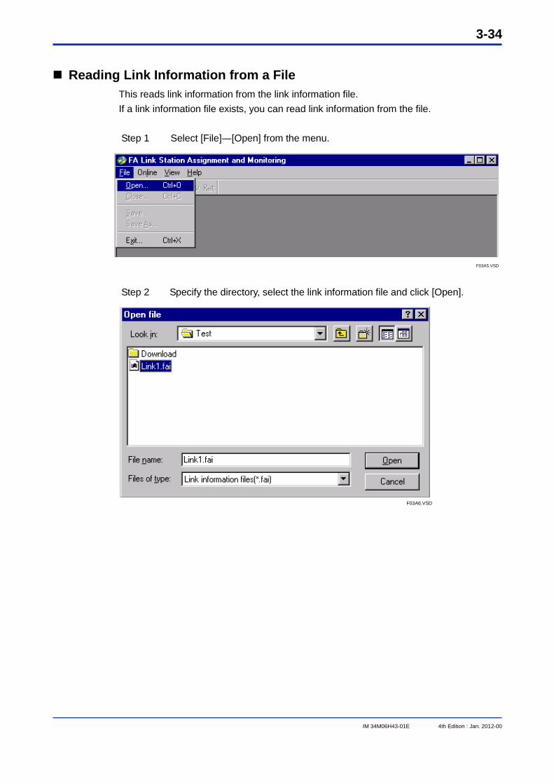
Reading Link Information from a File This reads link information from the link information file. If a link information file exists, you can read link information from the file. Step 1 Select [File]―[Open] from the menu.
F03A5.VSD Step 2 Specify the directory, select the link information file and click [Open].
F03A6.VSD
3-35
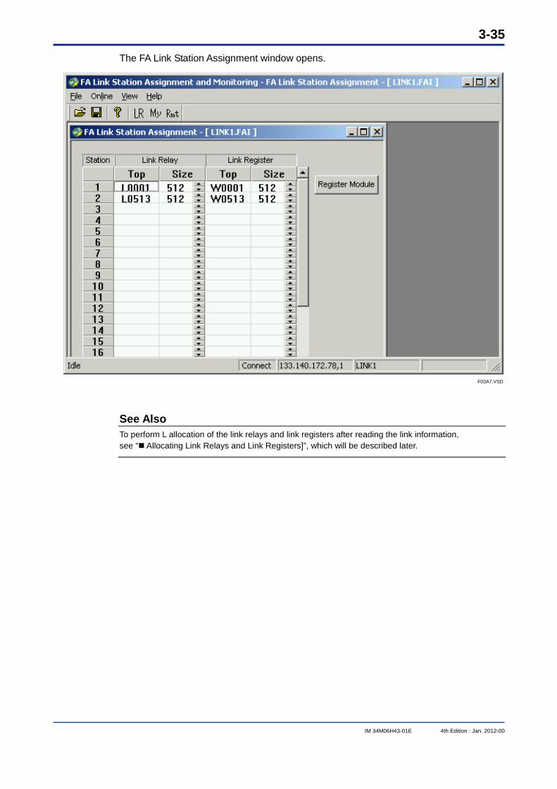
IM 34M06H43-01E 4th Edition : Jan. 2012-00
The FA Link Station Assignment window opens.
F03A7.VSD
See Also To perform L allocation of the link relays and link registers after reading the link information, see “ Allocating Link Relays and Link Registers]”, which will be described later.
3-36
IM 34M06H43-01E 4th Edition : Jan. 2012-00
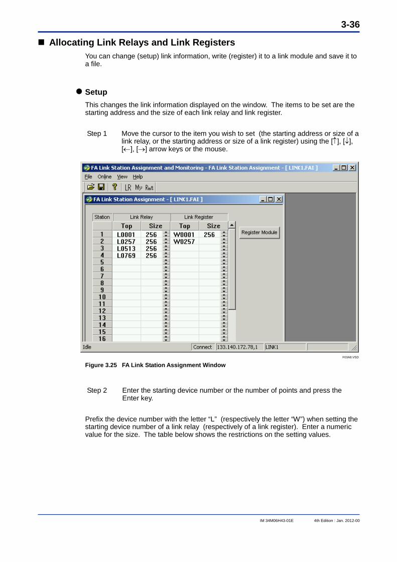
Allocating Link Relays and Link Registers You can change (setup) link information, write (register) it to a link module and save it to a file.
Setup This changes the link information displayed on the window. The items to be set are the starting address and the size of each link relay and link register.
Step 1 Move the cursor to the item you wish to set (the starting address or size of a link relay, or the starting address or size of a link register) using the [], [], [], [] arrow keys or the mouse.
F03A8.VSD Figure 3.25 FA Link Station Assignment Window
Step 2 Enter the starting device number or the number of points and press the
Enter key.
Prefix the device number with the letter “L” (respectively the letter “W”) when setting the starting device number of a link relay (respectively of a link register). Enter a numeric value for the size. The table below shows the restrictions on the setting values.
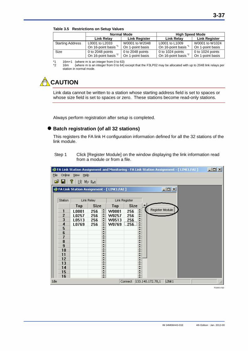
3-37
IM 34M06H43-01E 4th Edition : Jan. 2012-00
Table 3.5 Restrictions on Setup Values
Normal Mode High Speed Mode Link Relay Link Register Link Relay Link Register
Starting Address L0001 to L2033 On 16-point basis *1
W0001 to W2048 On 1-point basis
L0001 to L1009 On 16-point basis *1
W0001 to W1024 On 1-point basis
Size 0 to 2048 points On 16-point basis *2
0 to 2048 points On 1-point basis
0 to 1024 points On 16-point basis *2
0 to 1024 points On 1-point basis
*1 16m+1 (where m is an integer from 0 to 63) *2 16m (where m is an integer from 0 to 64) except that the F3LP02 may be allocated with up to 2048 link relays per
station in normal mode.
CAUTION Link data cannot be written to a station whose starting address field is set to spaces or whose size field is set to spaces or zero. These stations become read-only stations.
Always perform registration after setup is completed.
Batch registration (of all 32 stations) This registers the FA link H configuration information defined for all the 32 stations of the link module.
Step 1 Click [Register Module] on the window displaying the link information read from a module or from a file.
F03A9.VSD
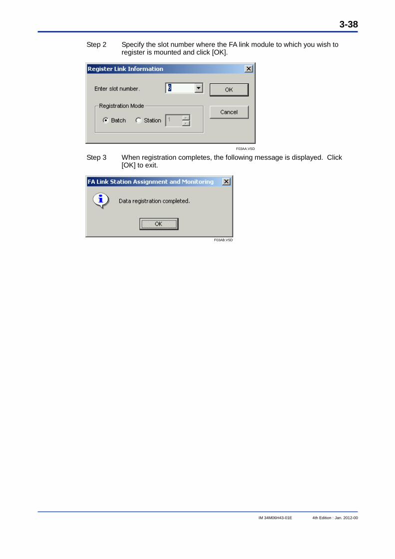
3-38
IM 34M06H43-01E 4th Edition : Jan. 2012-00
Step 2 Specify the slot number where the FA link module to which you wish to
register is mounted and click [OK].
F03AA.VSD Step 3 When registration completes, the following message is displayed. Click
[OK] to exit.
F03AB.VSD
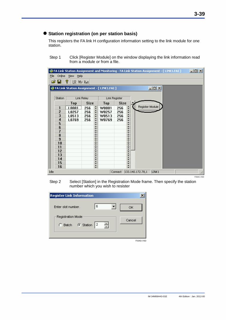
3-39
IM 34M06H43-01E 4th Edition : Jan. 2012-00
Station registration (on per station basis) This registers the FA link H configuration information setting to the link module for one station.
Step 1 Click [Register Module] on the window displaying the link information read from a module or from a file.
F03AC.VSD Step 2 Select [Station] in the Registration Mode frame. Then specify the station
number which you wish to resister
F03AD.VSD
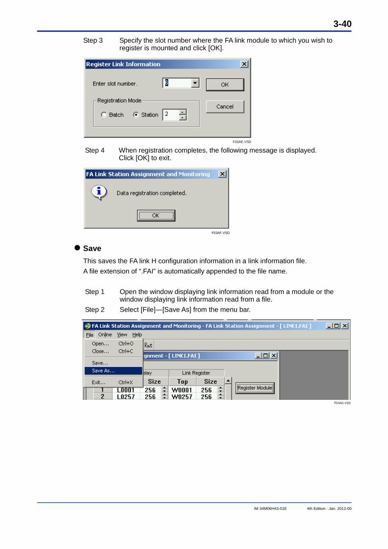
3-40
IM 34M06H43-01E 4th Edition : Jan. 2012-00
Step 3 Specify the slot number where the FA link module to which you wish to register is mounted and click [OK].
F03AE.VSD Step 4 When registration completes, the following message is displayed.
Click [OK] to exit.
F03AF.VSD
Save This saves the FA link H configuration information in a link information file. A file extension of “.FAI” is automatically appended to the file name.
Step 1 Open the window displaying link information read from a module or the window displaying link information read from a file.
Step 2 Select [File]―[Save As] from the menu bar.
F03AG.VSD
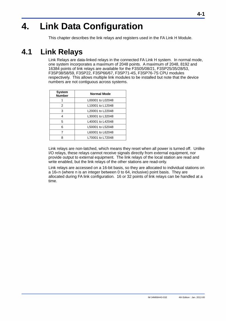
4-1
IM 34M06H43-01E 4th Edition : Jan. 2012-00
4. Link Data Configuration This chapter describes the link relays and registers used in the FA Link H Module.
4.1 Link Relays Link Relays are data-linked relays in the connected FA Link H system. In normal mode, one system incorporates a maximum of 2048 points. A maximum of 2048, 8192 and 16384 points of link relays are available for the F3S05/08/21, F3SP25/35/28/53, F3SP38/58/59, F3SP22, F3SP66/67, F3SP71-4S, F3SP76-7S CPU modules respectively. This allows multiple link modules to be installed but note that the device numbers are not contiguous across systems.
System Number Normal Mode
1 L00001 to L02048 2 L10001 to L12048 3 L20001 to L22048 4 L30001 to L32048 5 L40001 to L42048 6 L50001 to L52048 7 L60001 to L62048 8 L70001 to L72048
Link relays are non-latched, which means they reset when all power is turned off. Unlike I/O relays, these relays cannot receive signals directly from external equipment, nor provide output to external equipment. The link relays of the local station are read and write enabled, but the link relays of the other stations are read-only. Link relays are accessed on a 16-bit basis, so they are allocated to individual stations on a 16n (where n is an integer between 0 to 64, inclusive) point basis. They are allocated during FA link configuration. 16 or 32 points of link relays can be handled at a time.
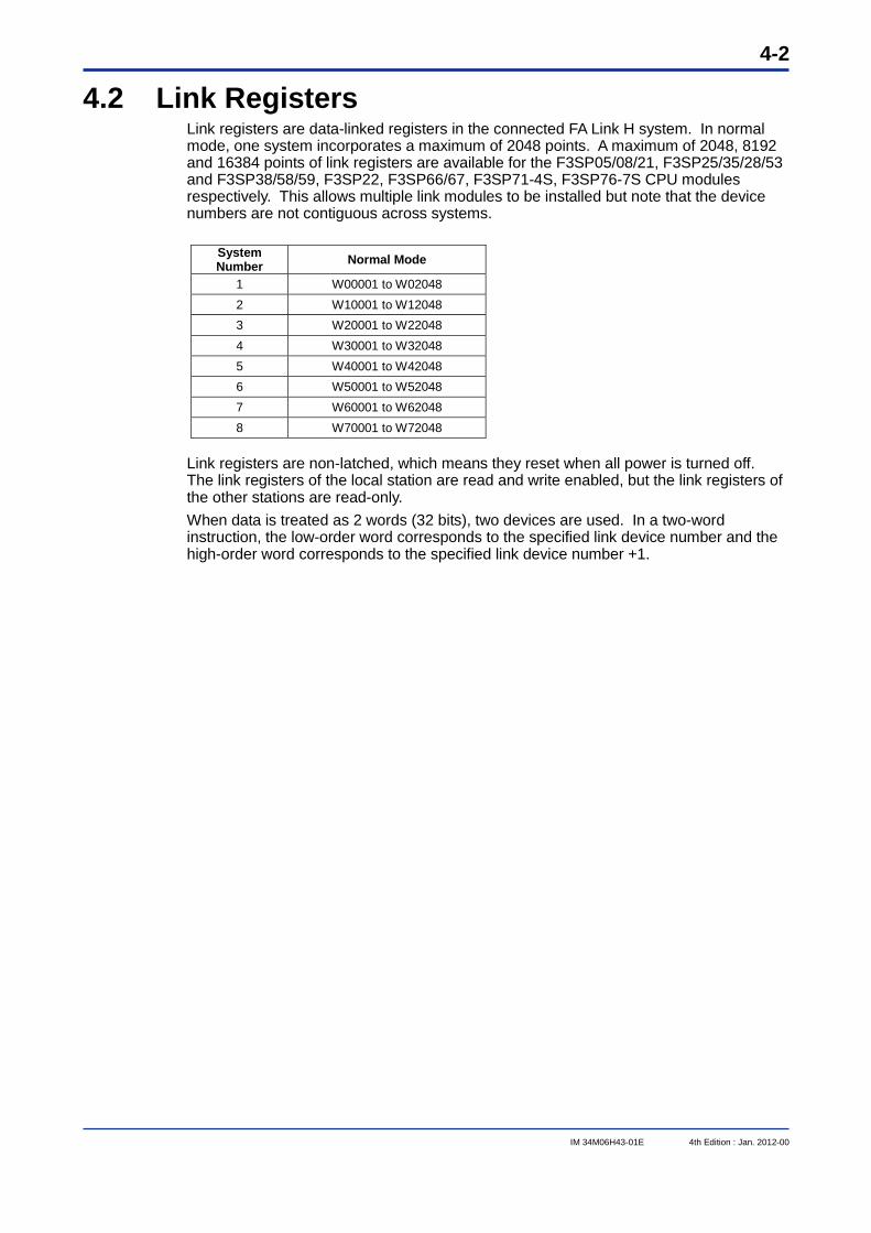
4-2
IM 34M06H43-01E 4th Edition : Jan. 2012-00
4.2 Link Registers Link registers are data-linked registers in the connected FA Link H system. In normal mode, one system incorporates a maximum of 2048 points. A maximum of 2048, 8192 and 16384 points of link registers are available for the F3SP05/08/21, F3SP25/35/28/53 and F3SP38/58/59, F3SP22, F3SP66/67, F3SP71-4S, F3SP76-7S CPU modules respectively. This allows multiple link modules to be installed but note that the device numbers are not contiguous across systems.
System Number Normal Mode
1 W00001 to W02048 2 W10001 to W12048 3 W20001 to W22048 4 W30001 to W32048 5 W40001 to W42048 6 W50001 to W52048 7 W60001 to W62048 8 W70001 to W72048
Link registers are non-latched, which means they reset when all power is turned off. The link registers of the local station are read and write enabled, but the link registers of the other stations are read-only. When data is treated as 2 words (32 bits), two devices are used. In a two-word instruction, the low-order word corresponds to the specified link device number and the high-order word corresponds to the specified link device number +1.
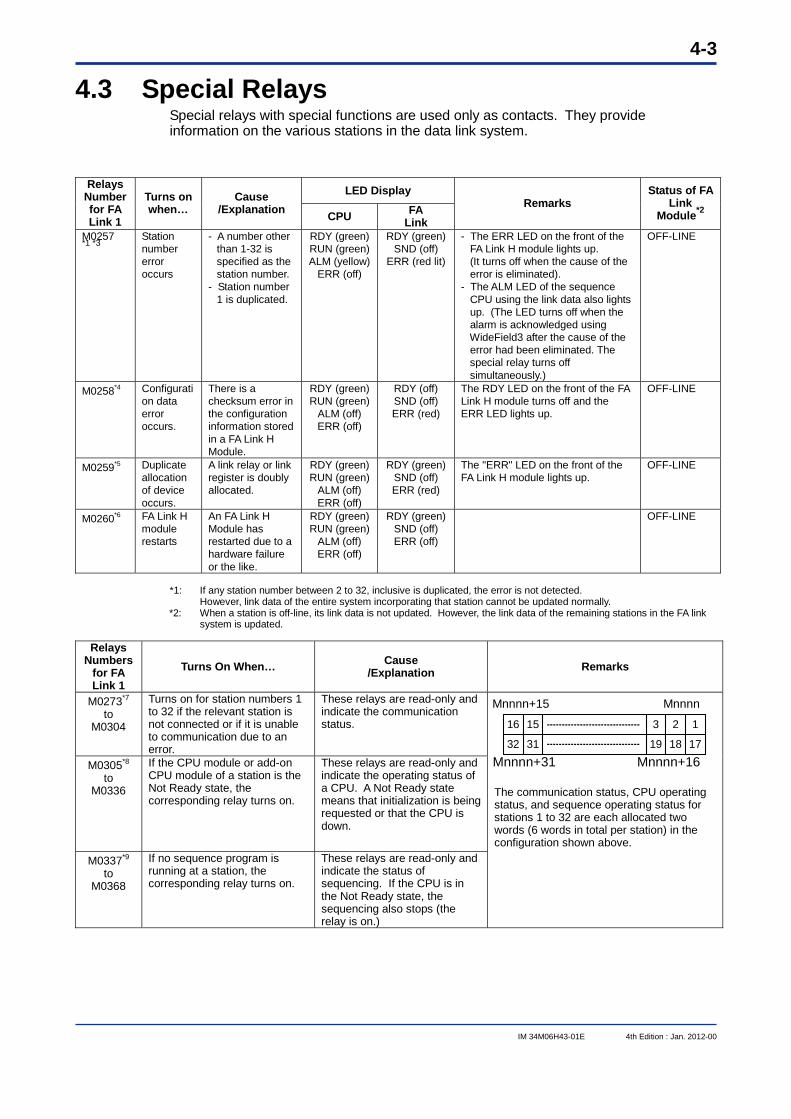
4-3
IM 34M06H43-01E 4th Edition : Jan. 2012-00
4.3 Special Relays Special relays with special functions are used only as contacts. They provide information on the various stations in the data link system.
LED Display Relays Number for FA Link 1
Turns on when…
Cause /Explanation CPU FA
Link Remarks
Status of FA Link
Module*2
M0257 *1 *3
Station number error occurs
- A number other than 1-32 is specified as the station number.
- Station number 1 is duplicated.
RDY (green) RUN (green) ALM (yellow)
ERR (off)
RDY (green) SND (off)
ERR (red lit)
- The ERR LED on the front of the FA Link H module lights up. (It turns off when the cause of the error is eliminated). - The ALM LED of the sequence CPU using the link data also lights up. (The LED turns off when the alarm is acknowledged using WideField3 after the cause of the error had been eliminated. The special relay turns off simultaneously.)
OFF-LINE
M0258*4 Configuration data error occurs.
There is a checksum error in the configuration information stored in a FA Link H Module.
RDY (green) RUN (green)
ALM (off) ERR (off)
RDY (off) SND (off) ERR (red)
The RDY LED on the front of the FA Link H module turns off and the ERR LED lights up.
OFF-LINE
M0259*5 Duplicate allocation of device occurs.
A link relay or link register is doubly allocated.
RDY (green) RUN (green)
ALM (off) ERR (off)
RDY (green) SND (off) ERR (red)
The "ERR" LED on the front of the FA Link H module lights up.
OFF-LINE
M0260*6 FA Link H module restarts
An FA Link H Module has restarted due to a hardware failure or the like.
RDY (green) RUN (green)
ALM (off) ERR (off)
RDY (green) SND (off) ERR (off)
OFF-LINE
*1: If any station number between 2 to 32, inclusive is duplicated, the error is not detected.
However, link data of the entire system incorporating that station cannot be updated normally. *2: When a station is off-line, its link data is not updated. However, the link data of the remaining stations in the FA link
system is updated.
Relays Numbers
for FA Link 1
Turns On When… Cause /Explanation Remarks
M0273*7 to
M0304
Turns on for station numbers 1 to 32 if the relevant station is not connected or if it is unable to communication due to an error.
These relays are read-only and indicate the communication status.
M0305*8 to
M0336
If the CPU module or add-on CPU module of a station is the Not Ready state, the corresponding relay turns on.
These relays are read-only and indicate the operating status of a CPU. A Not Ready state means that initialization is being requested or that the CPU is down.
M0337*9 to
M0368
If no sequence program is running at a station, the corresponding relay turns on.
These relays are read-only and indicate the status of sequencing. If the CPU is in the Not Ready state, the sequencing also stops (the relay is on.)
16 15 3 2 1
19 18 173132 The communication status, CPU operating status, and sequence operating status for stations 1 to 32 are each allocated two words (6 words in total per station) in the configuration shown above.
Mnnnn+31 Mnnnn+16
Mnnnn+15 Mnnnn
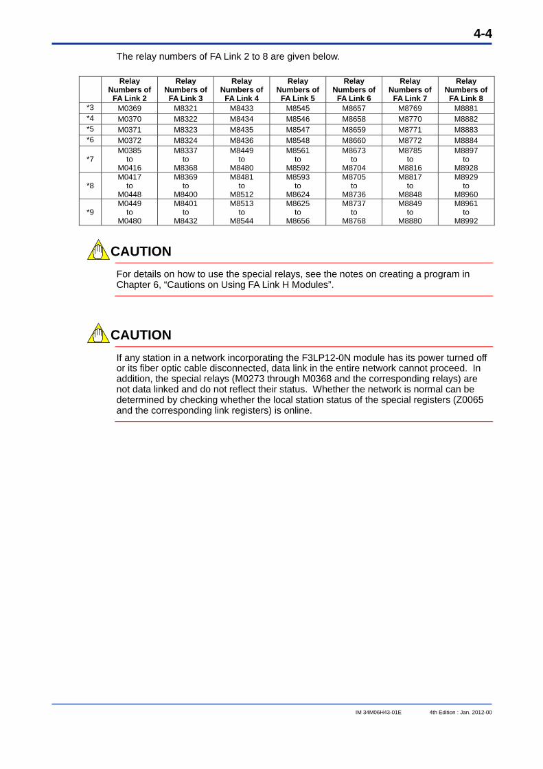
4-4
IM 34M06H43-01E 4th Edition : Jan. 2012-00
The relay numbers of FA Link 2 to 8 are given below.
Relay Numbers of
FA Link 2
Relay Numbers of
FA Link 3
Relay Numbers of
FA Link 4
Relay Numbers of
FA Link 5
Relay Numbers of
FA Link 6
Relay Numbers of
FA Link 7
Relay Numbers of
FA Link 8 *3 M0369 M8321 M8433 M8545 M8657 M8769 M8881 *4 M0370 M8322 M8434 M8546 M8658 M8770 M8882 *5 M0371 M8323 M8435 M8547 M8659 M8771 M8883 *6 M0372 M8324 M8436 M8548 M8660 M8772 M8884
*7 M0385
to M0416
M8337 to
M8368
M8449 to
M8480
M8561 to
M8592
M8673 to
M8704
M8785 to
M8816
M8897 to
M8928
*8 M0417
to M0448
M8369 to
M8400
M8481 to
M8512
M8593 to
M8624
M8705 to
M8736
M8817 to
M8848
M8929 to
M8960
*9 M0449
to M0480
M8401 to
M8432
M8513 to
M8544
M8625 to
M8656
M8737 to
M8768
M8849 to
M8880
M8961 to
M8992
CAUTION
For details on how to use the special relays, see the notes on creating a program in Chapter 6, “Cautions on Using FA Link H Modules”.
CAUTION
If any station in a network incorporating the F3LP12-0N module has its power turned off or its fiber optic cable disconnected, data link in the entire network cannot proceed. In addition, the special relays (M0273 through M0368 and the corresponding relays) are not data linked and do not reflect their status. Whether the network is normal can be determined by checking whether the local station status of the special registers (Z0065 and the corresponding link registers) is online.
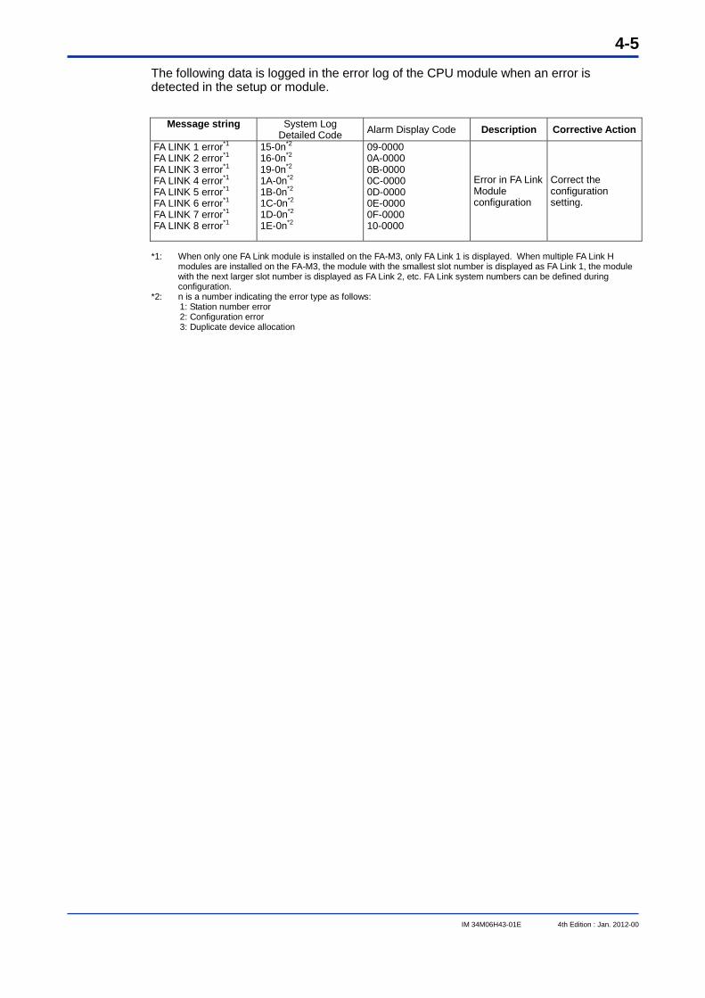
4-5
IM 34M06H43-01E 4th Edition : Jan. 2012-00
The following data is logged in the error log of the CPU module when an error is detected in the setup or module.
Message string
System Log Detailed Code Alarm Display Code Description Corrective Action
FA LINK 1 error*1 FA LINK 2 error*1
FA LINK 3 error*1
FA LINK 4 error*1
FA LINK 5 error*1
FA LINK 6 error*1
FA LINK 7 error*1
FA LINK 8 error*1
15-0n*2
16-0n*2
19-0n*2
1A-0n*2
1B-0n*2
1C-0n*2
1D-0n*2
1E-0n*2
09-0000 0A-0000 0B-0000 0C-0000 0D-0000 0E-0000 0F-0000 10-0000
Error in FA Link Module configuration
Correct the configuration setting.
*1: When only one FA Link module is installed on the FA-M3, only FA Link 1 is displayed. When multiple FA Link H
modules are installed on the FA-M3, the module with the smallest slot number is displayed as FA Link 1, the module with the next larger slot number is displayed as FA Link 2, etc. FA Link system numbers can be defined during configuration.
*2: n is a number indicating the error type as follows: 1: Station number error 2: Configuration error 3: Duplicate device allocation
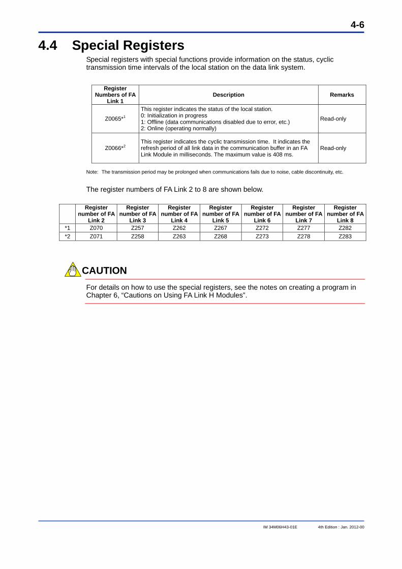
4-6
IM 34M06H43-01E 4th Edition : Jan. 2012-00
4.4 Special Registers Special registers with special functions provide information on the status, cyclic transmission time intervals of the local station on the data link system.
Register Numbers of FA
Link 1 Description Remarks
Z0065*1
This register indicates the status of the local station. 0: Initialization in progress 1: Offline (data communications disabled due to error, etc.) 2: Online (operating normally)
Read-only
Z0066*2 This register indicates the cyclic transmission time. It indicates the refresh period of all link data in the communication buffer in an FA Link Module in milliseconds. The maximum value is 408 ms.
Read-only
Note: The transmission period may be prolonged when communications fails due to noise, cable discontinuity, etc. The register numbers of FA Link 2 to 8 are shown below.
Register
number of FA Link 2
Register number of FA
Link 3
Register number of FA
Link 4
Register number of FA
Link 5
Register number of FA
Link 6
Register number of FA
Link 7
Register number of FA
Link 8 *1 Z070 Z257 Z262 Z267 Z272 Z277 Z282 *2 Z071 Z258 Z263 Z268 Z273 Z278 Z283
CAUTION
For details on how to use the special registers, see the notes on creating a program in Chapter 6, “Cautions on Using FA Link H Modules”.
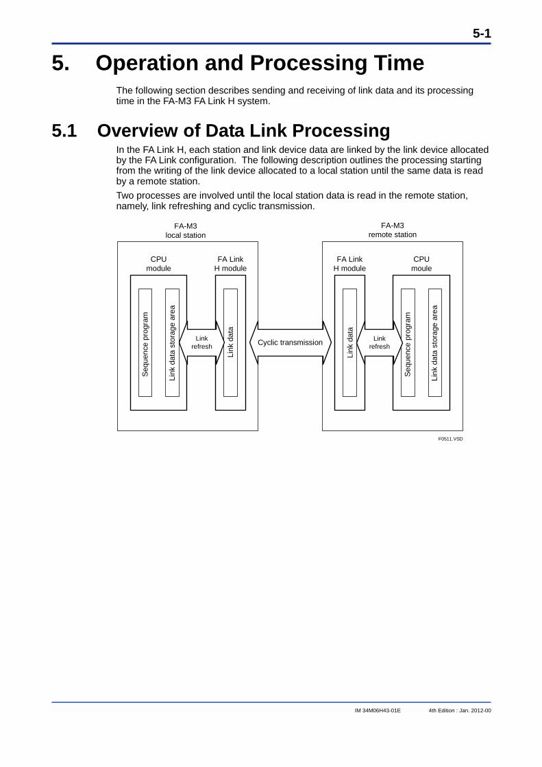
5-1
IM 34M06H43-01E 4th Edition : Jan. 2012-00
5. Operation and Processing Time The following section describes sending and receiving of link data and its processing time in the FA-M3 FA Link H system.
5.1 Overview of Data Link Processing In the FA Link H, each station and link device data are linked by the link device allocated by the FA Link configuration. The following description outlines the processing starting from the writing of the link device allocated to a local station until the same data is read by a remote station. Two processes are involved until the local station data is read in the remote station, namely, link refreshing and cyclic transmission.
FA-M3 local station
FA-M3 remote station
CPU module
FA LinkH module
FA LinkH module
CPUmoule
Link refresh
Cyclic transmission
F0511.VSD
Link refresh
Seq
uenc
e pr
ogra
m
Link
dat
a st
orag
e ar
ea
Link
dat
a
Link
dat
a
Sequ
ence
pro
gram
Link
dat
a st
orag
e ar
ea
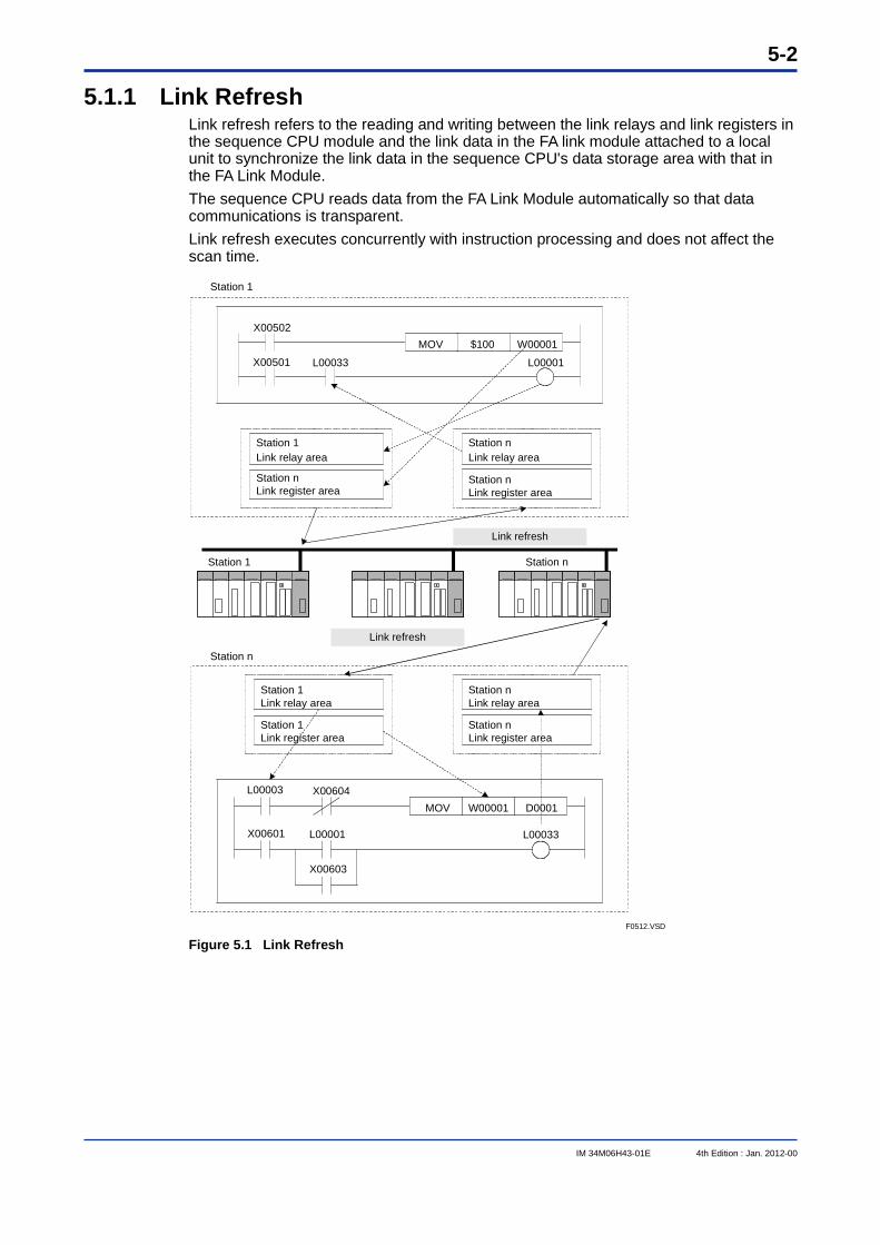
5-2
IM 34M06H43-01E 4th Edition : Jan. 2012-00
5.1.1 Link Refresh Link refresh refers to the reading and writing between the link relays and link registers in the sequence CPU module and the link data in the FA link module attached to a local unit to synchronize the link data in the sequence CPU's data storage area with that in the FA Link Module. The sequence CPU reads data from the FA Link Module automatically so that data communications is transparent. Link refresh executes concurrently with instruction processing and does not affect the scan time.
X00501
MOV $100X00502
L00033 L00001
W00001
Station 1Link relay area
Station nLink register area
Station nLink relay area
Station nLink register area
Station 1Link relay area
Station 1Link register area
Station nLink relay area
Station nLink register area
X00601
MOV W00001
L00001 L00033
D0001X00604
X00603
L00003
Station n
Station 1
Station 1 Station n
Link refresh
Link refresh
F0512.VSD Figure 5.1 Link Refresh
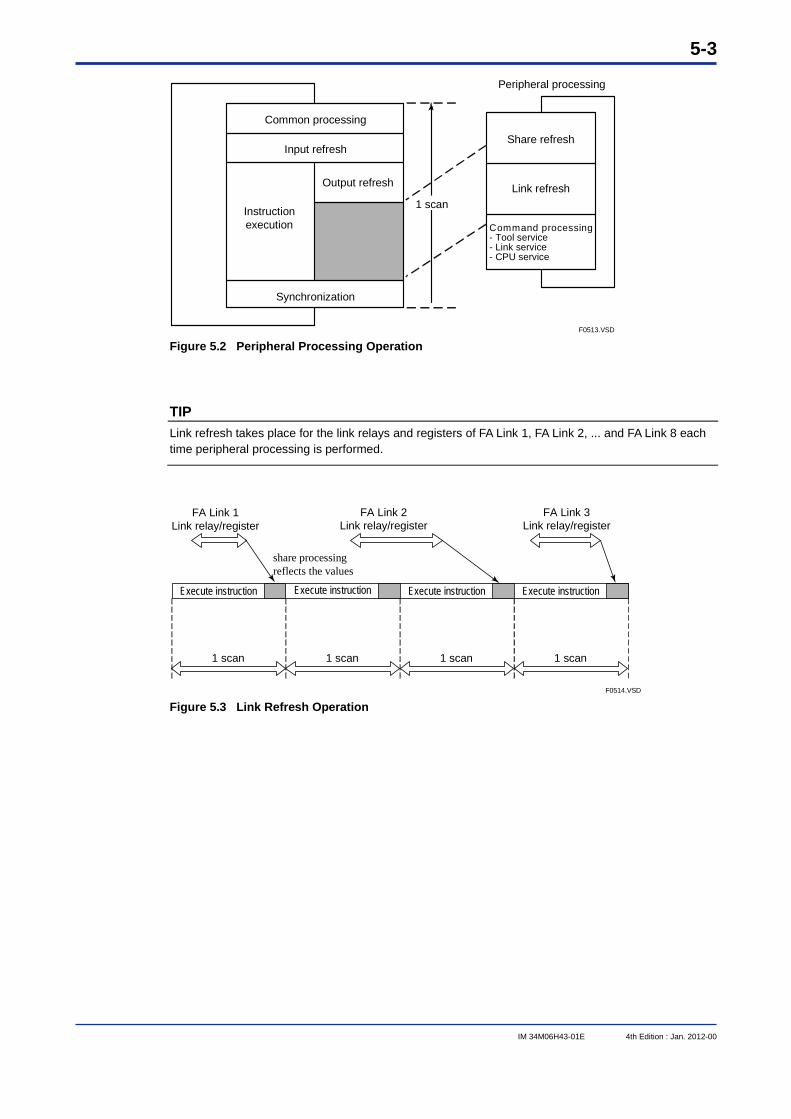
5-3
IM 34M06H43-01E 4th Edition : Jan. 2012-00
F0513.VSD
Common processing
1 scan
Synchronization
Instruction execution
Output refresh Link refresh
Share refresh
Command processing- Tool service- Link service- CPU service
Peripheral processing
Input refresh
Figure 5.2 Peripheral Processing Operation
TIP Link refresh takes place for the link relays and registers of FA Link 1, FA Link 2, ... and FA Link 8 each time peripheral processing is performed.
F0514.VSD
FA Link 1Link relay/register
FA Link 2Link relay/register
FA Link 3Link relay/register
share processing reflects the values
Execute instruction Execute instruction Execute instruction Execute instruction
1 scan1 scan1 scan1 scan
Figure 5.3 Link Refresh Operation
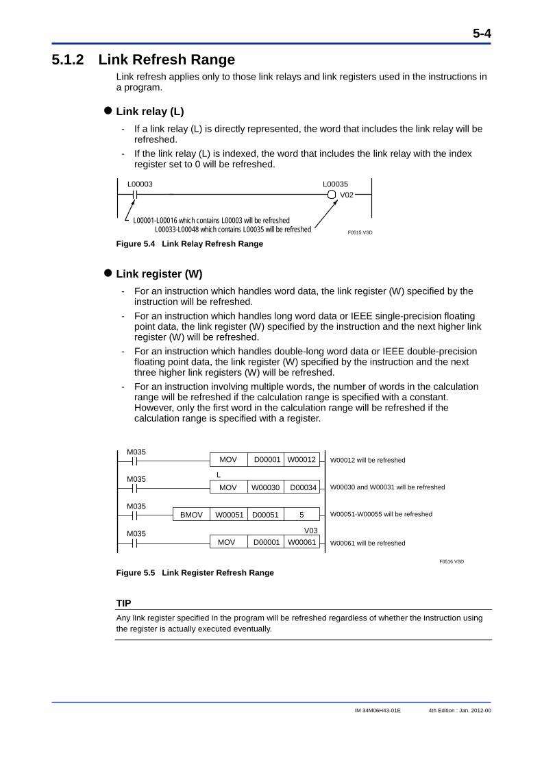
5-4
IM 34M06H43-01E 4th Edition : Jan. 2012-00
5.1.2 Link Refresh Range Link refresh applies only to those link relays and link registers used in the instructions in a program.
Link relay (L) - If a link relay (L) is directly represented, the word that includes the link relay will be
refreshed. - If the link relay (L) is indexed, the word that includes the link relay with the index
register set to 0 will be refreshed.
F0515.VSD
L00003 L00035V02
L00001-L00016 which contains L00003 will be refreshedL00033-L00048 which contains L00035 will be refreshed
Figure 5.4 Link Relay Refresh Range
Link register (W) - For an instruction which handles word data, the link register (W) specified by the
instruction will be refreshed. - For an instruction which handles long word data or IEEE single-precision floating
point data, the link register (W) specified by the instruction and the next higher link register (W) will be refreshed.
- For an instruction which handles double-long word data or IEEE double-precision floating point data, the link register (W) specified by the instruction and the next three higher link registers (W) will be refreshed.
- For an instruction involving multiple words, the number of words in the calculation range will be refreshed if the calculation range is specified with a constant. However, only the first word in the calculation range will be refreshed if the calculation range is specified with a register.
MOV W00012D00001M035
MOV D00034W00030
W00061D00001
M035
W00051BMOV 5
V03
D00051M035
MOVM035
F0516.VSD
W00012 will be refreshed
W00030 and W00031 will be refreshed
W00051-W00055 will be refreshed
W00061 will be refreshed
L
Figure 5.5 Link Register Refresh Range
TIP Any link register specified in the program will be refreshed regardless of whether the instruction using the register is actually executed eventually.
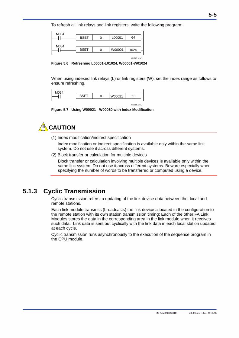
5-5
IM 34M06H43-01E 4th Edition : Jan. 2012-00
To refresh all link relays and link registers, write the following program:
1024W00001
0BSET 64L00001M034
M034
F0517.VSD
BSET 0
Figure 5.6 Refreshing L00001-L01024, W00001-W01024
When using indexed link relays (L) or link registers (W), set the index range as follows to ensure refreshing.
10W00021M034
F0518.VSD
BSET 0
Figure 5.7 Using W00021 - W00030 with Index Modification
CAUTION
(1) Index modification/indirect specification Index modification or indirect specification is available only within the same link system. Do not use it across different systems.
(2) Block transfer or calculation for multiple devices Block transfer or calculation involving multiple devices is available only within the same link system. Do not use it across different systems. Beware especially when specifying the number of words to be transferred or computed using a device.
5.1.3 Cyclic Transmission Cyclic transmission refers to updating of the link device data between the local and remote stations. Each link module transmits (broadcasts) the link device allocated in the configuration to the remote station with its own station transmission timing; Each of the other FA Link Modules stores the data in the corresponding area in the link module when it receives such data. Link data is sent out cyclically with the link data in each local station updated at each cycle. Cyclic transmission runs asynchronously to the execution of the sequence program in the CPU module.
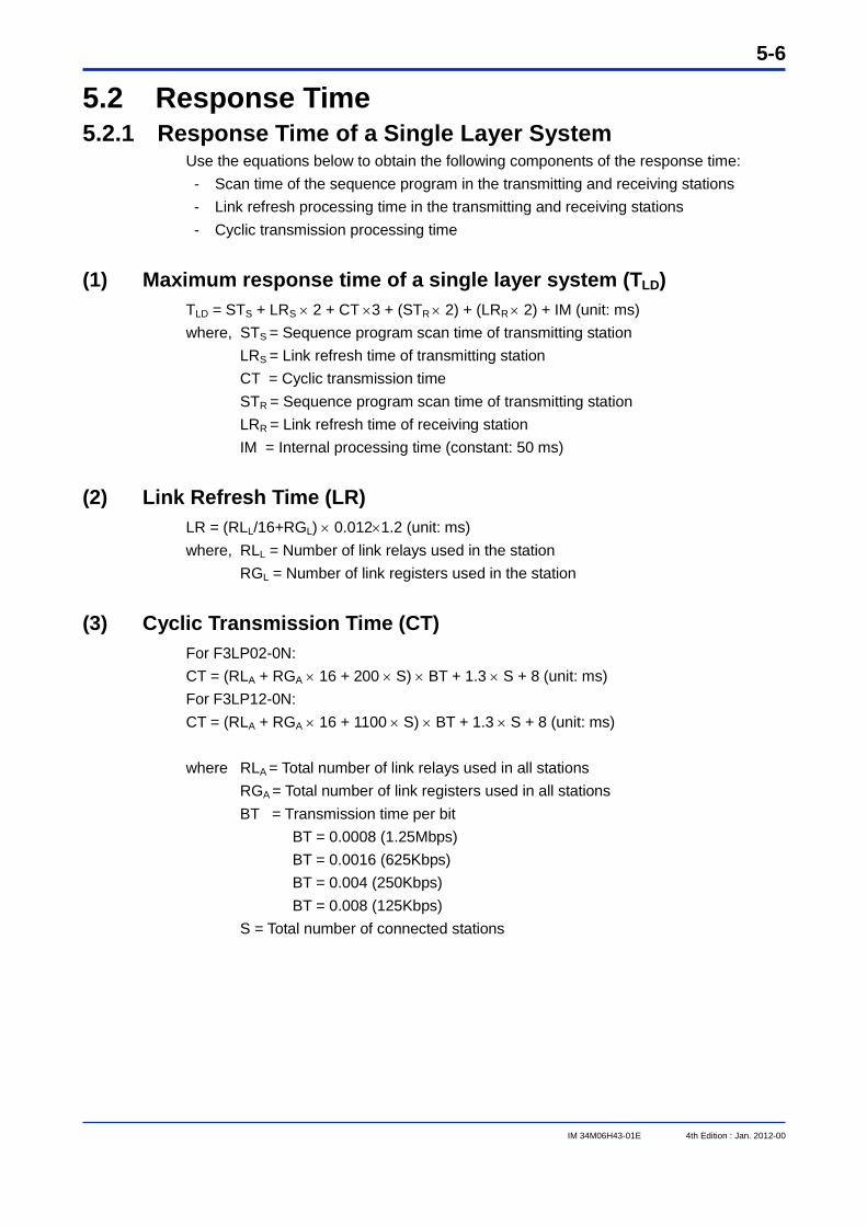
5-6
IM 34M06H43-01E 4th Edition : Jan. 2012-00
5.2 Response Time 5.2.1 Response Time of a Single Layer System
Use the equations below to obtain the following components of the response time: - Scan time of the sequence program in the transmitting and receiving stations - Link refresh processing time in the transmitting and receiving stations - Cyclic transmission processing time
(1) Maximum response time of a single layer system (TLD) TLD = STS + LRS 2 + CT 3 + (STR 2) + (LRR 2) + IM (unit: ms) where, STS = Sequence program scan time of transmitting station LRS = Link refresh time of transmitting station CT = Cyclic transmission time STR = Sequence program scan time of transmitting station LRR = Link refresh time of receiving station IM = Internal processing time (constant: 50 ms)
(2) Link Refresh Time (LR) LR = (RLL/16+RGL) 0.0121.2 (unit: ms) where, RLL = Number of link relays used in the station RGL = Number of link registers used in the station
(3) Cyclic Transmission Time (CT) For F3LP02-0N: CT = (RLA + RGA 16 + 200 S) BT + 1.3 S + 8 (unit: ms) For F3LP12-0N: CT = (RLA + RGA 16 + 1100 S) BT + 1.3 S + 8 (unit: ms) where RLA = Total number of link relays used in all stations RGA = Total number of link registers used in all stations BT = Transmission time per bit BT = 0.0008 (1.25Mbps) BT = 0.0016 (625Kbps) BT = 0.004 (250Kbps) BT = 0.008 (125Kbps) S = Total number of connected stations
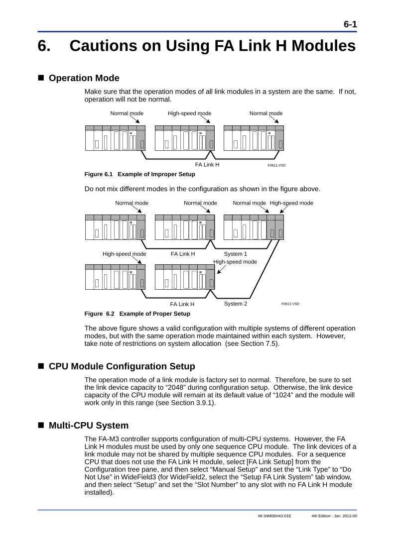
6-1
IM 34M06H43-01E 4th Edition : Jan. 2012-00
6. Cautions on Using FA Link H Modules
Operation Mode Make sure that the operation modes of all link modules in a system are the same. If not, operation will not be normal.
FA Link H
Normal mode
F0611.VSD
High-speed mode Normal mode
Figure 6.1 Example of Improper Setup
Do not mix different modes in the configuration as shown in the figure above.
FA Link H System 1
FA Link H System 2
Normal mode Normal mode Normal mode High-speed mode
High-speed modeHigh-speed mode
F0612.VSD Figure 6.2 Example of Proper Setup
The above figure shows a valid configuration with multiple systems of different operation modes, but with the same operation mode maintained within each system. However, take note of restrictions on system allocation (see Section 7.5).
CPU Module Configuration Setup The operation mode of a link module is factory set to normal. Therefore, be sure to set the link device capacity to “2048” during configuration setup. Otherwise, the link device capacity of the CPU module will remain at its default value of “1024” and the module will work only in this range (see Section 3.9.1).
Multi-CPU System The FA-M3 controller supports configuration of multi-CPU systems. However, the FA Link H modules must be used by only one sequence CPU module. The link devices of a link module may not be shared by multiple sequence CPU modules. For a sequence CPU that does not use the FA Link H module, select [FA Link Setup] from the Configuration tree pane, and then select “Manual Setup” and set the “Link Type” to “Do Not Use” in WideField3 (for WideField2, select the “Setup FA Link System” tab window, and then select “Setup” and set the “Slot Number” to any slot with no FA Link H module installed).
6-2
IM 34M06H43-01E 4th Edition : Jan. 2012-00
Programming Precautions - If a transmitting station fails, the contents of the data of that station are not assured.
To check whether the data of a station is valid, verify the status of the station and the execution status of the sequence program of the said station using special relays. If these states are normal, the data is correctly updated.
- The special relays associated with the status of the remote stations of the FA Link are valid only when the local station is connected on the network (normal communications). To verify that the local station is connected on the network, check that the local station status (as indicated by a special register) is online.
CAUTION
If any station in a network incorporating the F3LP12-0N module has its power turned off or its fiber optic cable disconnected, data link in the entire network cannot proceed. In addition, the special relays (M0273 through M0368 and the corresponding relays) are not data linked and do not reflect their status. Whether the network is normal can be determined by checking whether the local station status of the special registers (Z0065 and the corresponding link registers) is online.
Checking Link Data Allocation The link data allocation is checked each time allocation (FA Link H configuration) is made or power supply is applied. If duplicate allocation is present, error occurs (ERR LED of the module lights up) at all the stations with duplication. However, if duplication is with the master station (station with station number “01”), error occurs in all slave stations (all stations excluding the master station).
Precautions when Setting Station Numbers - Note that no error will be detected and indicated by the display LED or special relay
if any station number within the range 02–32 is duplicated. - Note that link data on the entire FA Link system will not be correctly updated if any
station number within the range 02–32 is duplicated.
Powering On - For the F3LP02-0N module, power supply may be applied to the master and slave
stations in any order. - For the F3LP12-0N module, apply power to all the slave stations first before
applying power to the master station.
CAUTION
For the F3LP12-0N module, data link continues among the stations that are powered on provided the master station is turned on.
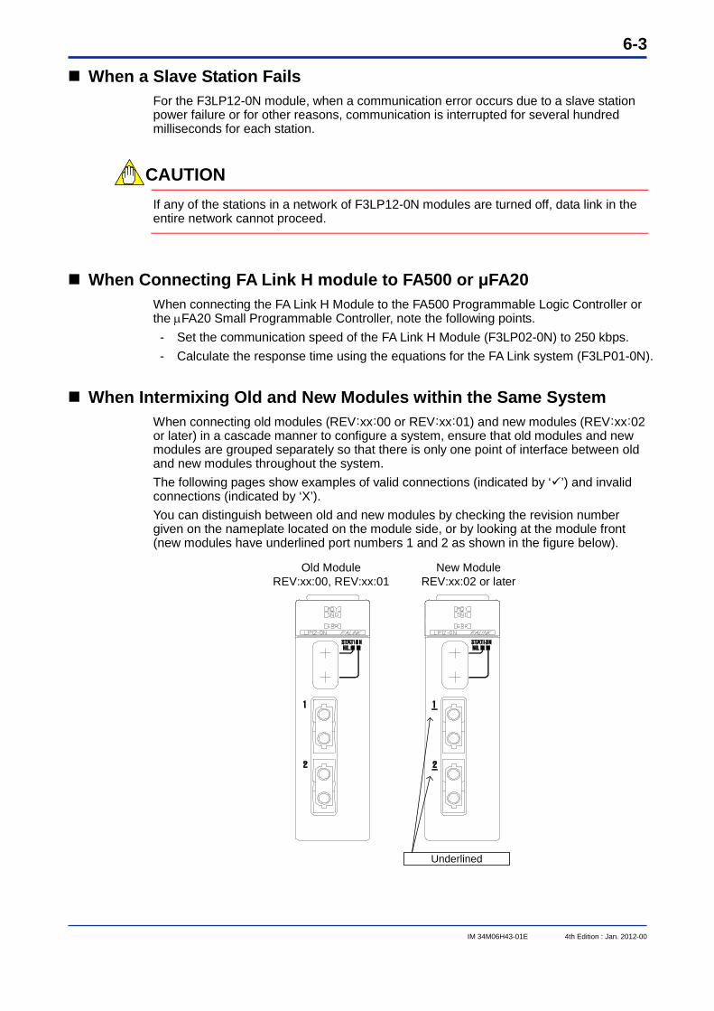
6-3
IM 34M06H43-01E 4th Edition : Jan. 2012-00
When a Slave Station Fails For the F3LP12-0N module, when a communication error occurs due to a slave station power failure or for other reasons, communication is interrupted for several hundred milliseconds for each station.
CAUTION
If any of the stations in a network of F3LP12-0N modules are turned off, data link in the entire network cannot proceed.
When Connecting FA Link H module to FA500 or μFA20 When connecting the FA Link H Module to the FA500 Programmable Logic Controller or the FA20 Small Programmable Controller, note the following points. - Set the communication speed of the FA Link H Module (F3LP02-0N) to 250 kbps. - Calculate the response time using the equations for the FA Link system (F3LP01-0N).
When Intermixing Old and New Modules within the Same System When connecting old modules (REV:xx:00 or REV:xx:01) and new modules (REV:xx:02 or later) in a cascade manner to configure a system, ensure that old modules and new modules are grouped separately so that there is only one point of interface between old and new modules throughout the system. The following pages show examples of valid connections (indicated by ‘’) and invalid connections (indicated by ‘X’). You can distinguish between old and new modules by checking the revision number given on the nameplate located on the module side, or by looking at the module front (new modules have underlined port numbers 1 and 2 as shown in the figure below).
Underlined
Old ModuleREV:xx:00, REV:xx:01
New ModuleREV:xx:02 or later
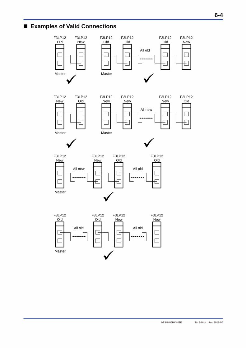
6-4
IM 34M06H43-01E 4th Edition : Jan. 2012-00
Examples of Valid Connections
F3LP12Old
F3LP12New
Master
F3LP12New
F3LP12Old
Master
F3LP12Old
F3LP12New
Master
F3LP12Old
F3LP12Old
F3LP12New
F3LP12Old
Master
F3LP12New
F3LP12New
F3LP12New
F3LP12Old
Master
F3LP12New
F3LP12Old
F3LP12Old
F3LP12New
Master
F3LP12Old
F3LP12New
All old
All old All old
All new
All new
All old
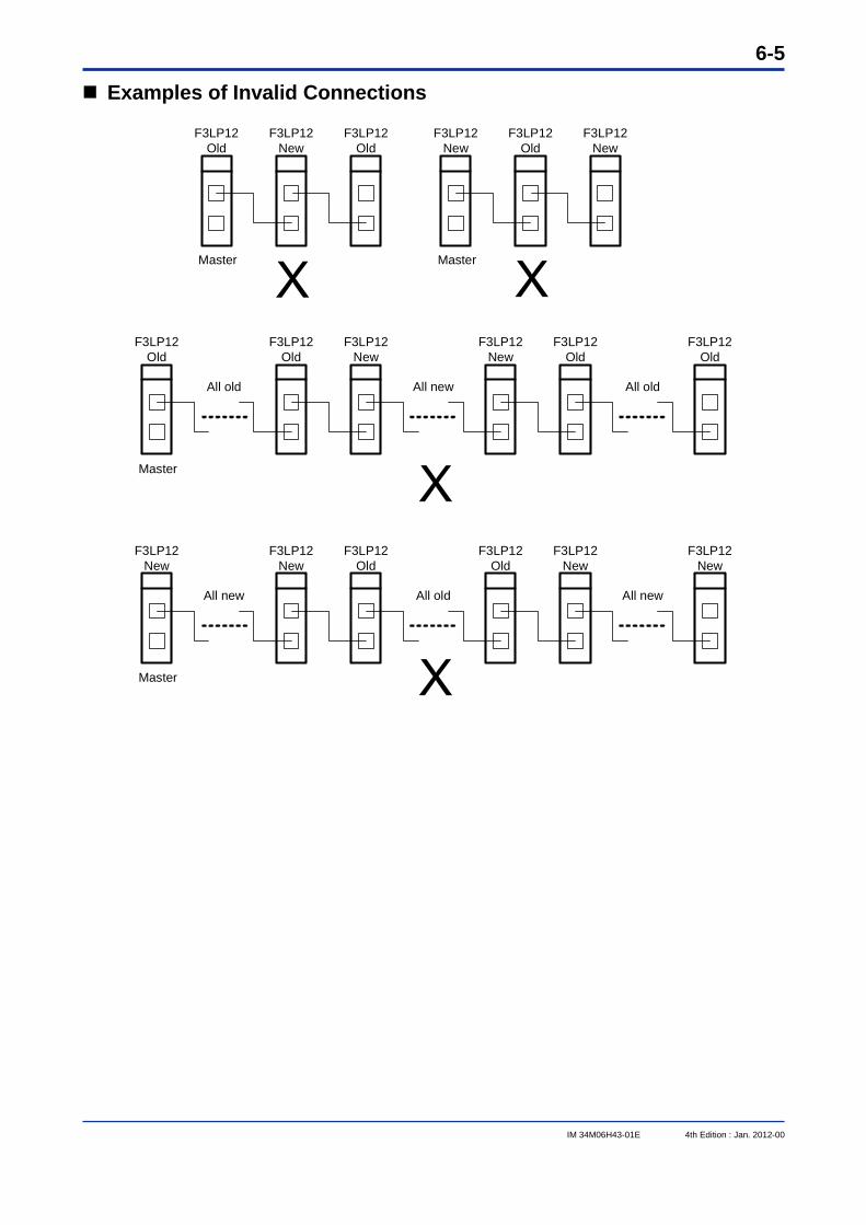
6-5
IM 34M06H43-01E 4th Edition : Jan. 2012-00
Examples of Invalid Connections
F3LP12Old
F3LP12Old
Master
F3LP12New
F3LP12Old
F3LP12New
Master
F3LP12Old
F3LP12New
F3LP12New
F3LP12New
Master
F3LP12Old
F3LP12Old
F3LP12Old
All old All oldAll new
F3LP12New
F3LP12Old
Master
F3LP12New
F3LP12Old
F3LP12New
F3LP12New
All new All newAll old
X X
X
X

Blank Page
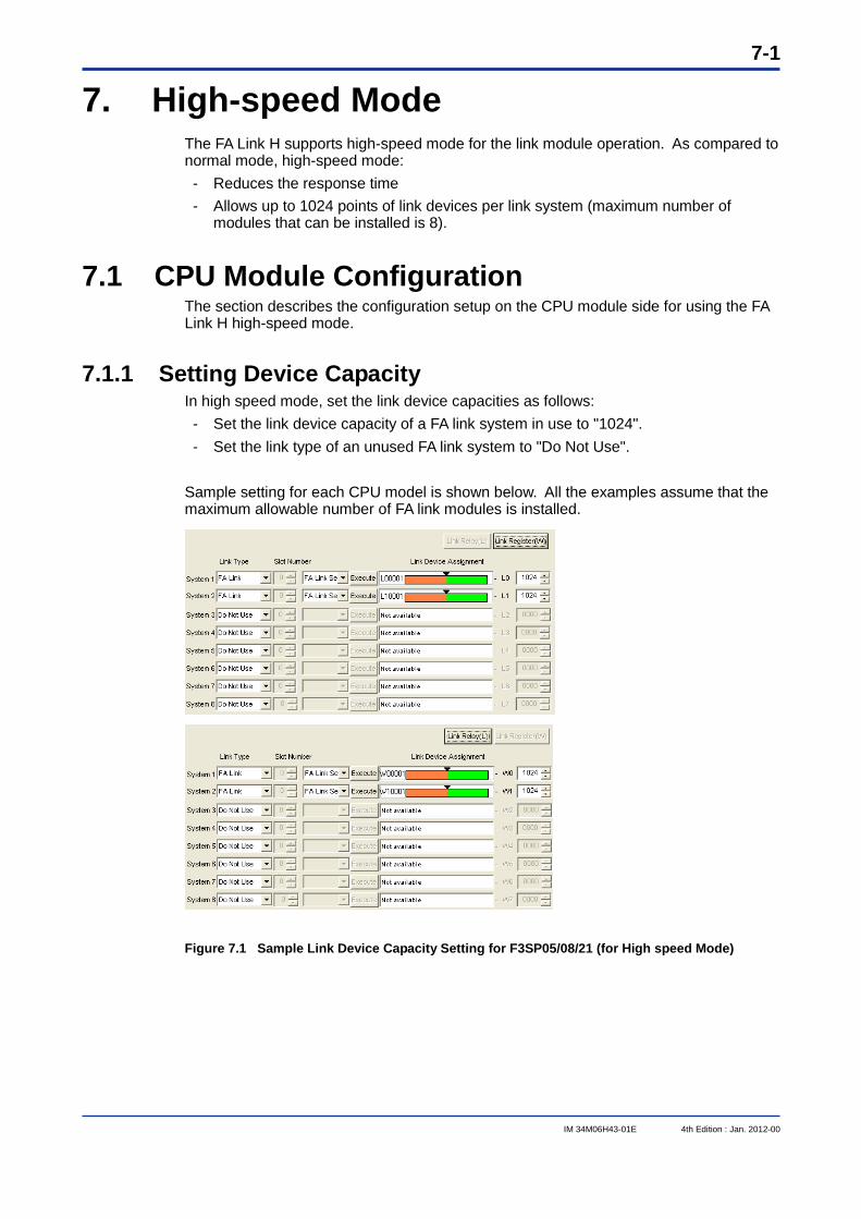
7-1
IM 34M06H43-01E 4th Edition : Jan. 2012-00
7. High-speed Mode The FA Link H supports high-speed mode for the link module operation. As compared to normal mode, high-speed mode: - Reduces the response time - Allows up to 1024 points of link devices per link system (maximum number of
modules that can be installed is 8).
7.1 CPU Module Configuration The section describes the configuration setup on the CPU module side for using the FA Link H high-speed mode.
7.1.1 Setting Device Capacity In high speed mode, set the link device capacities as follows: - Set the link device capacity of a FA link system in use to "1024". - Set the link type of an unused FA link system to "Do Not Use".
Sample setting for each CPU model is shown below. All the examples assume that the maximum allowable number of FA link modules is installed.
Figure 7.1 Sample Link Device Capacity Setting for F3SP05/08/21 (for High speed Mode)
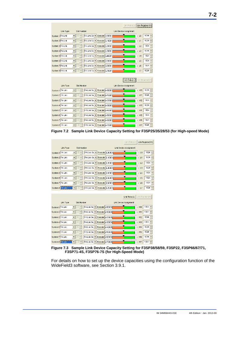
7-2
IM 34M06H43-01E 4th Edition : Jan. 2012-00
Figure 7.2 Sample Link Device Capacity Setting for F3SP25/35/28/53 (for High-speed Mode)
Figure 7.3 Sample Link Device Capacity Setting for F3SP38/58/59, F3SP22, F3SP66/67/71,
F3SP71-4S, F3SP76-7S (for High-Speed Mode)
For details on how to set up the device capacities using the configuration function of the WideField3 software, see Section 3.9.1.
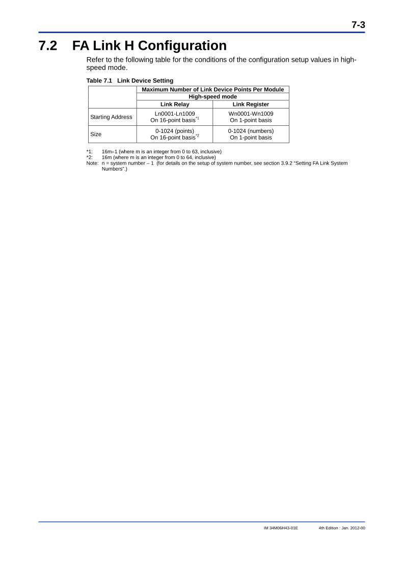
7-3
IM 34M06H43-01E 4th Edition : Jan. 2012-00
7.2 FA Link H Configuration Refer to the following table for the conditions of the configuration setup values in high-speed mode.
Table 7.1 Link Device Setting Maximum Number of Link Device Points Per Module
High-speed mode Link Relay Link Register
Starting Address Ln0001-Ln1009 On 16-point basis*1
Wn0001-Wn1009 On 1-point basis
Size 0-1024 (points) On 16-point basis*2
0-1024 (numbers) On 1-point basis
*1: 16m1 (where m is an integer from 0 to 63, inclusive) *2: 16m (where m is an integer from 0 to 64, inclusive) Note: n = system number – 1 (for details on the setup of system number, see section 3.9.2 “Setting FA Link System
Numbers”.)
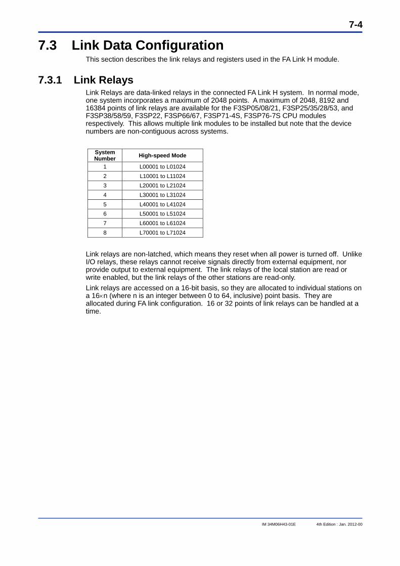
7-4
IM 34M06H43-01E 4th Edition : Jan. 2012-00
7.3 Link Data Configuration This section describes the link relays and registers used in the FA Link H module.
7.3.1 Link Relays Link Relays are data-linked relays in the connected FA Link H system. In normal mode, one system incorporates a maximum of 2048 points. A maximum of 2048, 8192 and 16384 points of link relays are available for the F3SP05/08/21, F3SP25/35/28/53, and F3SP38/58/59, F3SP22, F3SP66/67, F3SP71-4S, F3SP76-7S CPU modules respectively. This allows multiple link modules to be installed but note that the device numbers are non-contiguous across systems.
System Number High-speed Mode
1 L00001 to L01024 2 L10001 to L11024 3 L20001 to L21024 4 L30001 to L31024 5 L40001 to L41024 6 L50001 to L51024 7 L60001 to L61024 8 L70001 to L71024
Link relays are non-latched, which means they reset when all power is turned off. Unlike I/O relays, these relays cannot receive signals directly from external equipment, nor provide output to external equipment. The link relays of the local station are read or write enabled, but the link relays of the other stations are read-only. Link relays are accessed on a 16-bit basis, so they are allocated to individual stations on a 16n (where n is an integer between 0 to 64, inclusive) point basis. They are allocated during FA link configuration. 16 or 32 points of link relays can be handled at a time.
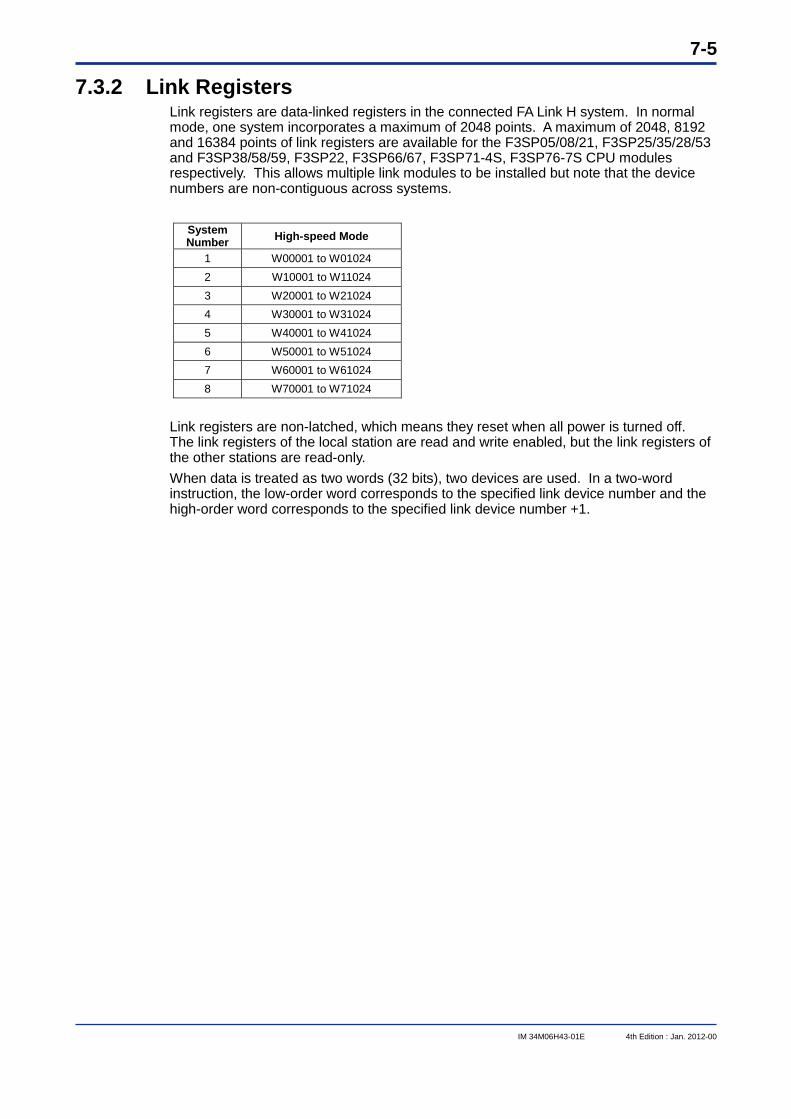
7-5
IM 34M06H43-01E 4th Edition : Jan. 2012-00
7.3.2 Link Registers Link registers are data-linked registers in the connected FA Link H system. In normal mode, one system incorporates a maximum of 2048 points. A maximum of 2048, 8192 and 16384 points of link registers are available for the F3SP05/08/21, F3SP25/35/28/53 and F3SP38/58/59, F3SP22, F3SP66/67, F3SP71-4S, F3SP76-7S CPU modules respectively. This allows multiple link modules to be installed but note that the device numbers are non-contiguous across systems.
System Number High-speed Mode
1 W00001 to W01024 2 W10001 to W11024 3 W20001 to W21024 4 W30001 to W31024 5 W40001 to W41024 6 W50001 to W51024 7 W60001 to W61024 8 W70001 to W71024
Link registers are non-latched, which means they reset when all power is turned off. The link registers of the local station are read and write enabled, but the link registers of the other stations are read-only. When data is treated as two words (32 bits), two devices are used. In a two-word instruction, the low-order word corresponds to the specified link device number and the high-order word corresponds to the specified link device number +1.
7-6
IM 34M06H43-01E 4th Edition : Jan. 2012-00
7.4 Response Time This section describes the calculation of the response time in high-speed mode. The basic processing is the same as that for normal mode.
7.4.1 Response Time of Layered System Use the equations below to obtain the following components of the response time: - Scan time of the sequence program in the transmitting and receiving stations - Link refresh processing time in the transmitting and receiving stations - Cyclic transmission processing time
(1) Maximum response time of a single layer system (TLD) TLD = STS + LRS 2 + CT 3 + (STR 2) + (LRR 2) + IM (unit: ms) where, STS = Sequence program scan time of transmitting station LRS = Link refresh time of receiving station CT = Cyclic transmission time STR = Sequence program scan time of receiving station LRR = Link refresh time of receiving station IM = Internal processing time (constant: 30 ms) Note: The internal processing time differs from that of normal mode (see Section 5.2.1
“Response Time of Single Layer System”)
(2) Link Refresh Time (LR) LR = (RLL/16+RGL) 0.0121.2 (unit: ms) where, RLL = Number of link relays used in the station RGL = Number of link registers used in the station
(3) Cyclic Transmission Time (CT) For F3LP02-0N: CT = (RLA + RGA 16 + 200 S) BT + 1.3 S + 8 (unit: ms) For F3LP12-0N: CT = (RLA + RGA 16 + 1100 S) BT + 1.3 S + 8 (unit: ms) where RLA = Total number of link relays used in all stations RGA = Total number of link registers used in all stations BT = Transmission time per bit BT = 0.0008 (1.25Mbps) BT = 0.0016 (625Kbps) BT = 0.004 (250Kbps) BT = 0.008 (125Kbps) S = Total number of connected stations
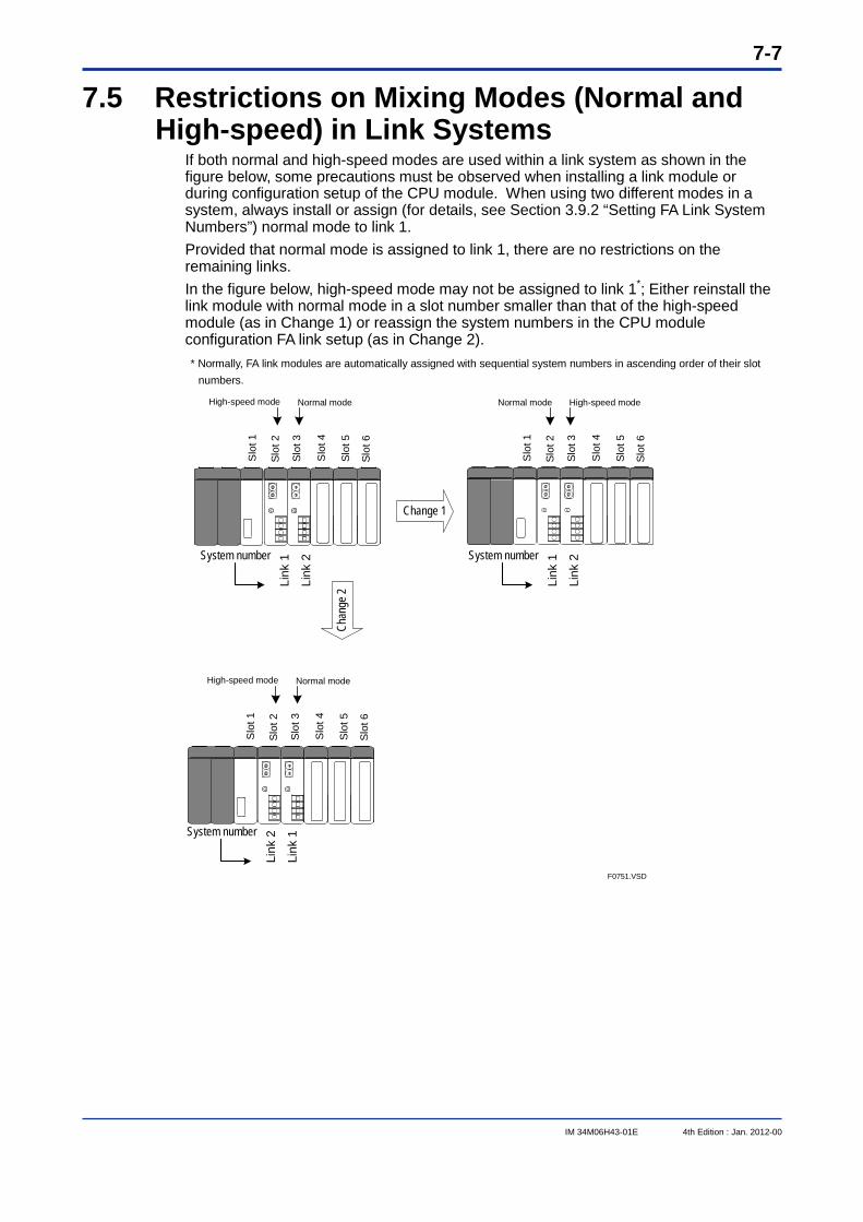
7-7
IM 34M06H43-01E 4th Edition : Jan. 2012-00
7.5 Restrictions on Mixing Modes (Normal and High-speed) in Link Systems
If both normal and high-speed modes are used within a link system as shown in the figure below, some precautions must be observed when installing a link module or during configuration setup of the CPU module. When using two different modes in a system, always install or assign (for details, see Section 3.9.2 “Setting FA Link System Numbers”) normal mode to link 1. Provided that normal mode is assigned to link 1, there are no restrictions on the remaining links. In the figure below, high-speed mode may not be assigned to link 1*; Either reinstall the link module with normal mode in a slot number smaller than that of the high-speed module (as in Change 1) or reassign the system numbers in the CPU module configuration FA link setup (as in Change 2). * Normally, FA link modules are automatically assigned with sequential system numbers in ascending order of their slot
numbers.
Change 1
Normal modeHigh-speed mode High-speed modeNormal mode
F0751.VSD
Cha
nge
2
Slo
t 1
Slot
2
Slot
3
Slo
t 4
Slot
5
Slot
6
Slo
t 1
Slot
2
Slot
3
Slo
t 4
Slot
5
Slot
6
System number
Link
2
Link
1 System number
Link
2
Link
1
System number
Link
1
Link
2
Normal modeHigh-speed mode
Slo
t 1
Slot
2
Slo
t 3
Slo
t 4
Slo
t 5
Slot
6
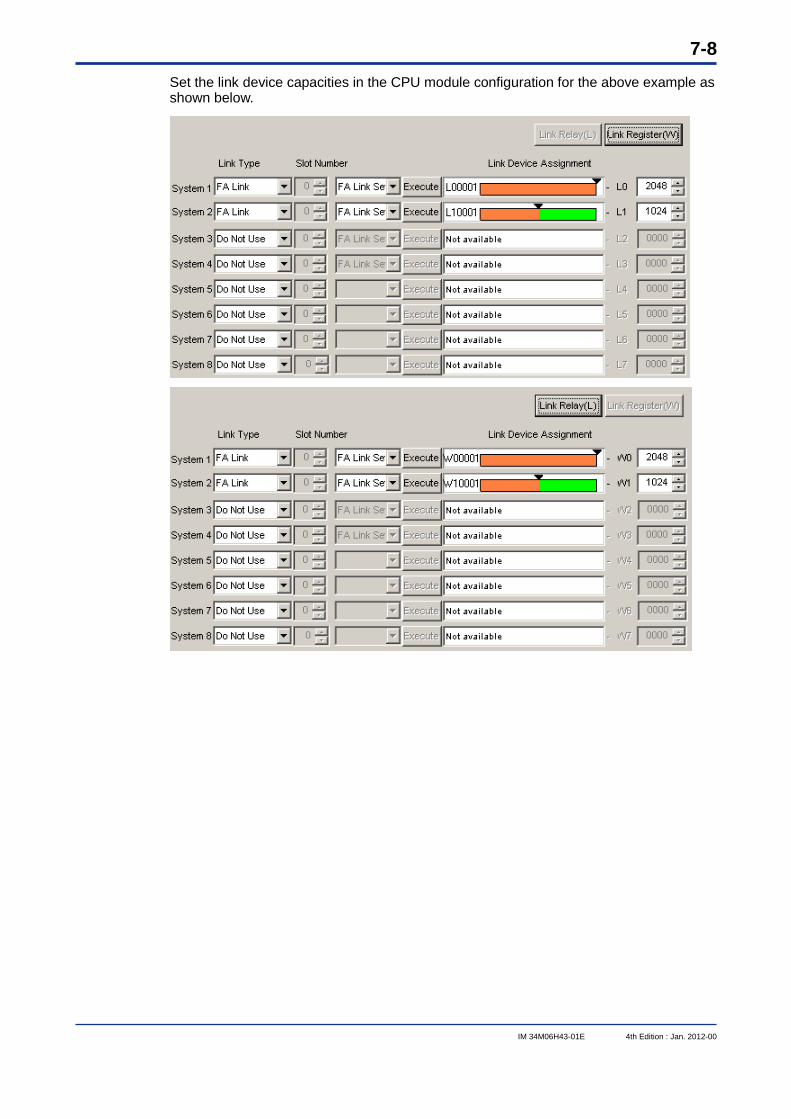
7-8
IM 34M06H43-01E 4th Edition : Jan. 2012-00
Set the link device capacities in the CPU module configuration for the above example as shown below.
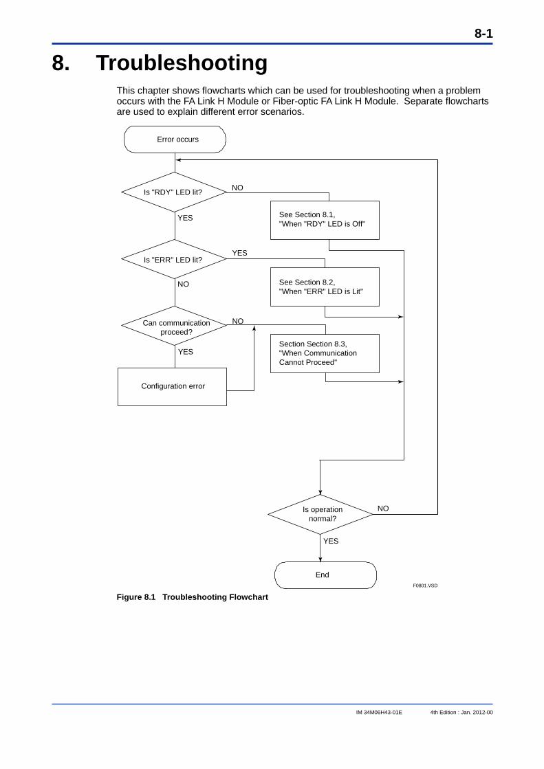
8-1
IM 34M06H43-01E 4th Edition : Jan. 2012-00
8. Troubleshooting This chapter shows flowcharts which can be used for troubleshooting when a problem occurs with the FA Link H Module or Fiber-optic FA Link H Module. Separate flowcharts are used to explain different error scenarios.
F0801.VSD
Error occurs
Is "RDY" LED lit?
Is "ERR" LED lit?
See Section 8.1,"When "RDY" LED is Off"
See Section 8.2,"When "ERR" LED is Lit"
Can communication proceed?
Configuration error
Section Section 8.3,"When Communication Cannot Proceed"
Is operation normal?
End
YES
YES
YES
NO
NO
NO
YES
NO
Figure 8.1 Troubleshooting Flowchart
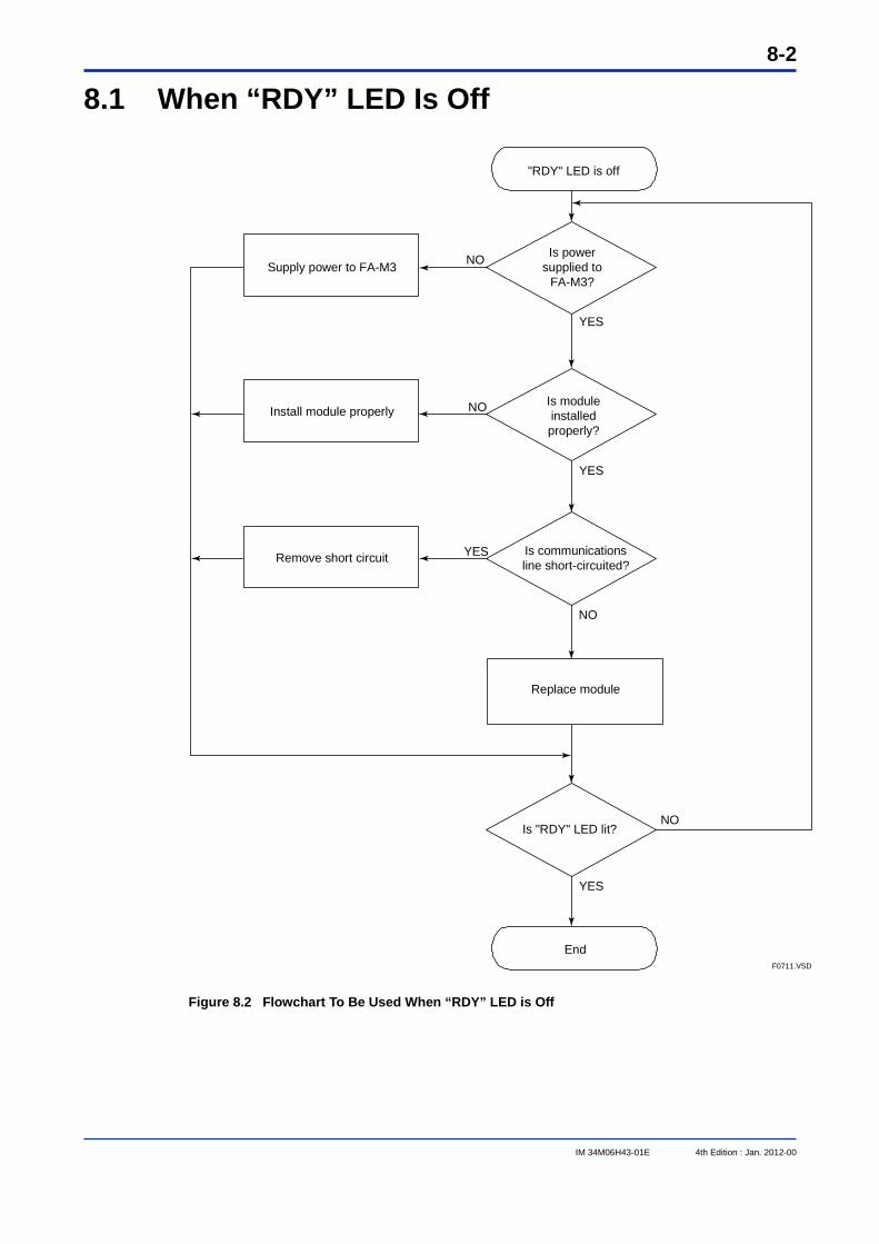
8-2
IM 34M06H43-01E 4th Edition : Jan. 2012-00
8.1 When “RDY” LED Is Off
F0711.VSD
"RDY" LED is off
End
YES
NO
Remove short circuit
NO
YES
NO
YES
NO
YES
Is "RDY" LED lit?
Replace module
Is communications line short-circuited?
Is module installed properly?
Is power supplied to
FA-M3?
Install module properly
Supply power to FA-M3
Figure 8.2 Flowchart To Be Used When “RDY” LED is Off
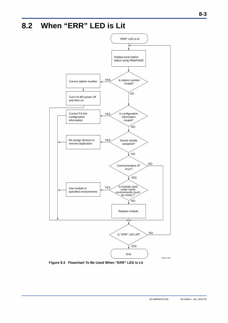
8-3
IM 34M06H43-01E 4th Edition : Jan. 2012-00
8.2 When “ERR” LED is Lit
F0721.VSD
YES
YES
NO
YES
NO
Turn FA-M3 power off and then on
"ERR" LED is lit
Is "ERR" LED off?
End
NO
NO
NO
YES
NO
YES
Replace module
Is module used under harsh
environments (such as noise) ?
Communication I/F error?
Device doubly assigned?
Is configuration information
invalid?
Is station number invalid?
Display local station status using WideField3
Correct station number
YESCorrect FA link configuration information
Re-assign devices to remove duplication
Use module in specified environments
Figure 8.3 Flowchart To Be Used When “ERR” LED is Lit
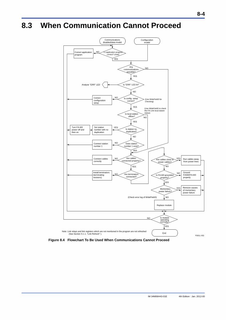
8-4
IM 34M06H43-01E 4th Edition : Jan. 2012-00
8.3 When Communication Cannot Proceed
F0831.VSD
NO
NO
NO
YES
NO
NO
NO
YES
NO
Ground FA500/FA-M3 properly
Remove causes of momentary power failure
(Check error log of WideField3)
Install terminators (terminating resistors)
Connect cables correctly
Connect station number 1
Turn FA-M3 power off and then on
Correct configuration setup
Analyse "ERR" LED
I s application program correct? (note)
Correct application program
Configuration invalid
(Use WideField3 for Checking)
(Use WideField3 to check the FA Link local statoin status)
Note: Link relays and link registers which are not mentioned in the program are not refreshed(See Section 5.1.1, "Link Refresh" ).
YES
YES
NO
YES
YES
NO
YES
Is config. setup correct?
Any communications
possible?
NO
YES
NO
YES
End
YES
YES
NO
NO
Replace module
Momentary power failure?
Is FA-M3 grounded properly?
Are cables close to power cables?
Is module operating normally?
Run cables away from power lines
Communications disabled/data invalid
Set station number with no duplication
Are terminators connected?
Are cables connected properly?
Does station number 1 exist?
Is station no. duplicated?
Is local station offline?
Is "ERR" LED lit?
Figure 8.4 Flowchart To Be Used When Communications Cannot Proceed
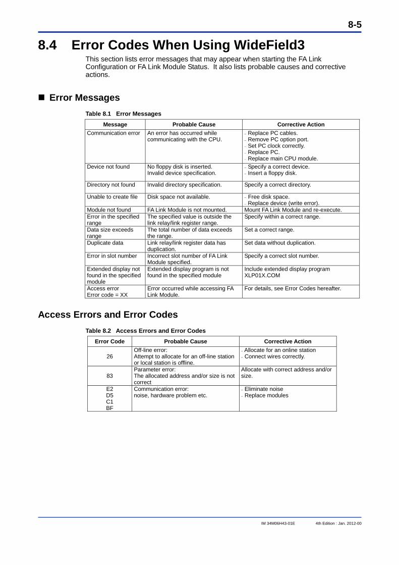
8-5
IM 34M06H43-01E 4th Edition : Jan. 2012-00
8.4 Error Codes When Using WideField3 This section lists error messages that may appear when starting the FA Link Configuration or FA Link Module Status. It also lists probable causes and corrective actions.
Error Messages Table 8.1 Error Messages
Message Probable Cause Corrective Action Communication error An error has occurred while
communicating with the CPU. Replace PC cables. Remove PC option port. Set PC clock correctly. Replace PC. Replace main CPU module.
Device not found No floppy disk is inserted. Invalid device specification.
Specify a correct device. Insert a floppy disk.
Directory not found Invalid directory specification. Specify a correct directory.
Unable to create file Disk space not available. Free disk space. Replace device (write error).
Module not found FA Link Module is not mounted. Mount FA Link Module and re-execute. Error in the specified range
The specified value is outside the link relay/link register range.
Specify within a correct range.
Data size exceeds range
The total number of data exceeds the range.
Set a correct range.
Duplicate data Link relay/link register data has duplication.
Set data without duplication.
Error in slot number Incorrect slot number of FA Link Module specified.
Specify a correct slot number.
Extended display not found in the specified module
Extended display program is not found in the specified module
Include extended display program XLP01X.COM
Access error Error code = XX
Error occurred while accessing FA Link Module.
For details, see Error Codes hereafter.
Access Errors and Error Codes Table 8.2 Access Errors and Error Codes
Error Code Probable Cause Corrective Action
26 Off-line error: Attempt to allocate for an off-line station or local station is offline.
Allocate for an online station Connect wires correctly.
83 Parameter error: The allocated address and/or size is not correct
Allocate with correct address and/or size.
E2 D5 C1 BF
Communication error: noise, hardware problem etc.
Eliminate noise Replace modules

Blank Page
Index-1
IM 34M06H43-01E 4th Edition : Jan. 2012-00
Index C cautions on using FA Link H modules...................6-1 caution when a slave station fails .........................6-3 communication status, checking.........................3-13 configuration setup .............................. 3-19, 6-1, 7-1 cyclic transmission................................................5-5
D data link processing ..............................................5-1 device capacity, setting............................... 3-20, 7-1
E error codes............................................................8-5
F FA Link H configuration............................... 3-31, 7-3 FA Link Module status.........................................3-14 FA Link system number, setting..........................3-26 fiber-optic cables...................................................2-2
H high-speed mode ..................................................7-1
L link data allocation, checking ................................6-2 link data configuration................................... 4-1, 7-4 link device .............................................................1-1 link refresh ............................................................5-2 link refresh range ..................................................5-4 link register ................................................... 4-2, 7-4 link relay........................................................ 4-1, 7-3
M module, setup and connection..............................3-1 multi-CPU system .................................................6-1 multi-layer system.................................................1-3
N normal mode and high-speed mode, mixing ........7-7
O operation mode................................viii, 1-1, 3-5, 6-1
P parameters, setting .............................................. 3-5
R response time ............................................... 5-6, 7-6
S special registers................................................... 4-6 special relays ....................................................... 4-3 startup procedure................................................. 3-1 station number, setting......................................... 3-4 status of local station, displaying ....................... 3-15 status of remote station, displaying ................... 3-17
T troubleshooting .................................................... 8-1 troubleshooting flowchart, when "ERR" LED is lit .............................................................. 8-3 troubleshooting flowchart, when "RDY" LED is off ............................................................. 8-2 troubleshooting flowchart, when communication cannot proceed .................................................... 8-4
FA-M3 FA Link H Module, Fiber-optic FA Link H Module Manual
IM 34M06H43-01E 4th Edition

Blank Page
i
IM 34M06H43-01E 4th Edition : Jan. 2012-00
Revision Information Document Name : FA Link H Module, Fiber-optic FA Link H Module Document No. : IM 34M06H43-01E
Edition Date Revised Item
1st Feb, 1999 New Publication
2nd Sep, 2001 Addition of explanations on support of CE Mark; Correction of typographical errors
3rd Apr, 2003 Addition of modules; Addition of Fiber-optic cable KM65; Modification for WideField2 support; Correction of errors
4th Jan. 2012 Addition of information on F3SP22, F3SP66, F3SP67, F3SP71-4S and F3SP76-7S; Addition of information on WideField3; Incorporation of addendum
Written by PLC Solution Department IA Systems Business Headquarters Yokogawa Electric Corporation Published by Yokogawa Electric Corporation 2-9-32 Nakacho, Musashino-shi, Tokyo, 180-8750, JAPAN Printed by Kohoku Publishing & Printing Inc.

Blank Page
Related Documents