ACTUATORS
1
CYLINDERGRIPPERS
ROTARY ACTUATORSGUIDE UNITS AND SLIDES

1.1/01
1GENERAL TECHNICAL DATA
MICRO-CYLINDER SERIES ISO 6432 Ø 8-25 mmAND ACCESSORIES
ROUND CYLINDER SERIES RNDC Ø 32-50 mmAND ACCESSORIES
CARTRIDGE MICRO-CYLINDER SERIES CRTC Ø 6-16 mm
SHORT-STROKE CYLINDERS SERIES SSCY Ø12-100 mmAND ACCESSORIES
COMPACT CYLINDER Ø 12-100 mmAND ACCESSORIES
COMPACT STOPPER CYLINDER Ø 20-30-50-80 mmAND ACCESSORIES
COMPACT CYLINDERS SERIES “CMPC” Ø 32÷80 TWO-FLAT
COMPACT CYLINDER ISO 21287 SERIES “LINER”, Ø 20÷100
CYLINDERS SERIES ISO 15552 (EX ISO 6431) Ø 32-125 mmAND ACCESSORIES
CYLINDERS SERIES ISO 15552 (EX ISO 6431) Ø 32-125 mm TYPE ARETRACTABLE SENSOR AND ACCESSORIES
CYLINDER SERIES “ISO 15552” SERIES 3 Ø 32÷100
CYLINDER SERIES ISO 15552 (EX ISO 6431) Ø 32-63 TWO-FLATAND ACCESSOIRES
CYLINDER SERIES ISO 15552 (EX ISO 6431) Ø 32-63 TYPE ARETRACTABLE SENSOR TWO FLAT AND ACCESSOIRES
CYLINDERS SERIES ISO 15552 (EX ISO 6431) Ø 160-200 mmAND ACCESSORIES
TWIN-ROD CYLINDER SERIES TWNC Ø 32-100 mmAND ACCESSORIES
RODLESS CYLINDER Ø 16-63 mmAND ACCESSORIES
RODLESS CYLINDER DOUBLE SERIES Ø 16-32AND ACCESSORIES
RODLESS CYLINDER Ø 16-40 WITH BALL CIRCULATION GUIDE
RODLESS CYLINDER WITH GUIDE “V” Ø 25-63AND ACCESSOIRES
RODLESS CYLINDER WITH MAGNETIC SLIDINGSERIES “MAGNETIC SLIDE” Ø 16-20-25
COMPACT GUIDED CYLINDER Ø 12-100 mmAND ACCESSORIES
STAINLESS STELL CYLINDERAND ACCESSOIRES
HYDRAULIC BRAKE SERIES BRK FOR ISO CYL. Ø 40-80 mmAND ACCESSORIES
INTEGRATED HYDRAULIC BRAKE
TESTER FOR MAGNETIC SENSORS
PNEUMATIC ACTUATORS CHAPTER 1.1
PAGE 1.1/02
PAGE 1.1/08
PAGE 1.1/19
PAGE 1.1/24
PAGE 1.1/26
PAGE 1.1/34
PAGE 1.1/54
CHAPTER NEWS PAGE 1
CHAPTER NEWS PAGE 116
PAGE 1.1/63
PAGE 1.1/72
CHAPTER NEWS PAGE 131
PAGE 1.1/89
PAGE 1.1/94
PAGE 1.1/103
PAGE 1.1/110
PAGE 1.1/117
PAGE 1.1/125
PAGE 1.1/127
PAGE 1.1/135
CHAPTER NEWS PAGE 111
PAGE 1.1/143
PAGE 1.1/149
PAGE 1.1/165
CHAPTER NEWS PAGE 11
PAGE 1.1/171

Compressed airThe cylinders have been designed for use with unlubricated air,in which case no maintenance is required. If lubricated air isused, lubrication must be continuous because the additionallubrication removes the lubricant applied at the factory.With reference to ISO/DIN 8573-1, the compressed air touse is class 3-4-3, i.e.:• solid particle classe 3: 10.000 particles/m3 with d<=1 micron and 500 particles/m3 with d<=5 micron.• humidity classe 4: Pressure dewpoint <= +3 °C• oil classe 3: Concentration total oil <=1 mg/m3.
Gasket materialPlease refer to page 6.1/08 of the technicaldocumentation for compatibility data.Some families of Metal Work cylinders are available withgaskets made of different materials.Polyurethane: the best in terms of long-life, resistance towear and reduced friction.Chemically compatible with:• Pure aliphatic hydrocarbons (butane, propane, gasoline).Any impurities (moisture, alcohol, acid or alkalinecompounds) can chemically attack polyurethane.• Mineral oil and grease (some additives can chemicallyattack the material)• Silicone oil and grease• Water up to +50°C• Resistance to ozone and ageingNot compatible with:• Ketones, esters, ethers• Alcohos, glycols• Hot water, steam, alkali, amines, acids.• Good elasticity down to –35°C (for low temperature PUversion only).NBR: These gaskets have a shorter life than polyurethanegaskets. However, they are recommended for use inenvironments causing the formation of water condensate,such as tropical climates, where polyurethane gaskets maytend to deteriorate quickly due to hydrolysis.Chemically compatible with:• Methane, butane, propane, oily acids• Aliphatic hydrocarbons• Lubrication oils• GasolineNot compatible with:• Ozone and exposure to sunlight.• Good elasticity down to –35°C (for low temperature NBRversion only).FKM/FPM: Can withstand temperatures as high as 150°C.This makes them ideal for use on rodless cylinders, high-speed applications, involving high temperatures at thesliding lips.Chemically compatible with:• Mineral oil and grease, slight swelling with oil gradeASTM no. 1 and 3.• Silicon oil and grease• Animal and vegetable oil and fat• Aliphatic hydrocarbons (gasoline, butane, propane,natural gas)• Aromatic hydrocarbons (benzol, toluene)• Chlorinated hydrocarbons (tetrachloroethylene)• Fuels• Ozone, atmospheric agents, ageingNot compatible with:• Polar solvents (acetone, methylethylchetone, diethyl ether,dioxane)• Glycol-based brake fluids• Ammonia gas, amines, alkali• Superheated water vapour• Low molecular organic acids (formic and acetic acid)
No-stick-slip cylinders:Standard cylinders are designed to ensure trouble-freeoperation under any conditions, particularly at high speed.Operation tends to be irregular and jerky at very low speedsin the presence of side loads. In this case, no-stick-slipcylinders are recommended as they allow smooth operation.These versions feature specific tribological properties andpolyurethane gaskets.
Radial oscillation of the piston rodThese cylinders have been designed to apply forces in thedirection of the axis and not to withstand side loads. If youintend to use the cylinder piston rod with side loads, theplay between the piston rod and guide bushing must betaken into account. Indicatively, each 100-mm strokecorresponds to 1-mm radial oscillation measured at theend of the piston rod.
Cylinder operating lifeThe life of cylinders depends on numerous factors includingaxial and radial loads, speed, frequency of use, temperature,shocks, air loss (limits). Below are a few factors that mustbe taken purely as a reference. They are not binding orguaranteed due to the variability of different factors.Without radial load:ISO 15552 cylinders and round cylinders with polyurethanegaskets: 15,000 km.ISO 15552 cylinders and round cylinders with NBR gaskets:8,000 km.ISO 6432 cylinders, SSC cylinders and compact cylinderswith polyurethane gaskets: 30 million cycles.ISO6432 cylinders and SSC cylinders with NRB gaskets:15 million cyclesRodless cylinders: 5,000 km
Stroke tolerancesThe actual cylinder stroke has a tolerance with respect tothe nominal stroke, in compliance with any applicable laws,within the following ranges:• ISO 15552 cylinders 32-50 -0 +2 mm
63-200 -0 +2.5 mm• ISO 6432 6432 8-25 -1 +1 mm• Round cylinders 32-50 -0,5 +1.5 mm• SSC cylinders 12-50 -1 +1 mm
63-100 -1 +1.5 mm• Compact cylinders 12-100 -0,5 +1.5 mm• Compact cylinders ISO 21287 20-100 -0,5 +1.5 mm• Rodless cylinders 16-40 -1 +2 mm
Strokes exceeding the maximum value specified inthe catalogueMetal Work can supply cylinders with strokes greater thanthose specified in the catalogue, considering the productiontechnological limits. The Metal Work Sales Department canprovide you will full details. However, it is up to the enduser to use these special cylinders properly, by guiding thepiston rod, avoiding peak loads, etc.
Magnetic sensorsThe magnetic field generated by permanent magnetshoused in the piston assembly changes in shape andintensity depending on the presence of magnetic metalmasses in the vicinity of the cylinder. These masses mayprevent the sensors from switching correctly, in which casenon-magnetic materials should be used. In particular, thetie rods of short-stroke and compact cylinders shouldpreferably be made of stainless steel.
1.1/02
GENERALE TECHNICAL DATA

1.1/03
1
25 32
During operation, the piston rod of thecylinder behaves like a rod subjectedto peak load (bending + compression).In the case of long strokes, it is neces-sary to make sure the diameter of thepiston rod is correct for the load appliedand the type of cylinder and piston rodmounting. The following formulae canbe used to do this.
A. Calculating the maximum force witha given stroke and piston rod diameter:
B. Calculating the minimum acceptablepiston rod diameter with a given strokeand force:
Where:F force applied [N]! diameter of the piston rod [mm]C stroke [mm]K free length coefficient depending
on the mounting – see diagrams
CALCULATING PEAK LOAD ON THE PISTON ROD
F ! ––––––––––20.350 !4
C2. K2
S " ––––––––––––F . C2. K2
20.350!""4
CHART OF SPEED / MAXIMUM ABSORBABLE LOAD
For the cylinder to reach the end-of-stroke position without sufferingdamaging impact due to intensity andrepetition, it is necessary to annul thekinetic energy of the moving mass andthe relative work generated. Themaximum absorbable load dependson the transference speed and theabsorption capacity of the standardpneumatic cushion in the variouscylinders. The chart gives the speedand absorbable mass in variousdiameters at a pressure of 6 bar.
CONSTRAINT K
2
0.7
0.5
2
1
1.5

1.1/04
FORCE OF SPRINGS IN SINGLE-ACTING CYLINDERS (THEORETICAL)
Boremm
Force with springcompressed N
Max. strokemm
Force with springextended N
32405063
6388
102102
250250250250
35516464
1216202532405063
67
121433457081
2525252550505050
1,53456
152025
ISO 15552 SINGLE-ACTING CYLINDERS SSC SINGLE-ACTING CYLINDERSBoremm
Force with springcompressed N
Max. strokemm
Force with springextended N
ISO 6432 SINGLE-ACTING CYLINDERSBoremm
Force with springcompressed N
Max. strokemm
Force with springextended N
81012162025
357
202228
505050505050
1135
1217
324050
8695
108
250250250
345062
Boremm
Force with springcompressed N
Max. strokemm
Force with springextended N
ROUND SINGLE-ACTING CYLINDERS
610166
10166
1016
3.7 7.8 7.2 3.9 9.613.3 3.9 9.113.3
5 5 5101010151515
–––––––––
Boremm
Force with springcompressed N
Max. strokemm
Force with springextended N
SINGLE-ACTING CARTRIDGE CYLINDERS
P = P1 +(P2 – P1)
Cmax––––––––––– • Cx
P1 = Force with spring extendedP2 = Force with spring compressedCx = Required strokeCmax = Max stroke
CONSUMPTION OF AIR IN THE CYLINDERS
Cylinderbore D
mm
Piston roddiameter
d mmMotion
1 bar 2 bar 3 bar 4 bar 5 bar 6 bar 7 bar 8 bar 9 bar 10 barAir consumption during thrust and traction in Nl/cm of stroke, depending on the working pressure P in bar at 20°C.Useful
areacm2
12
16
20
25
32
40
50
63
80
100
125
160
200
4
6
8
12
12
16
20
20
25
32
32
40
40
thrusttraction
thrusttraction
thrusttraction
thrusttraction
thrusttraction
thrusttraction
thrusttraction
thrusttraction
thrusttraction
thrusttraction
thrusttraction
thrusttraction
thrusttraction
1,131,00
2,011,73
3,142,64
4,913,78
8,046,91
12,5610,55
19,6316,49
31,1628,02
50,2445,36
78,5470,50
122,66114,67
201,06188,49
314,15301,59
0,00230,0020
0,00400,0035
0,00630,0053
0,00980,0076
0,0160,014
0,0250,021
0,0390,033
0,0620,056
0,1000,091
0,1570,141
0,2450,229
0,4020,377
0,6280,603
0,00340,0030
0,00600,0052
0,00940,0079
0,01470,0113
0,0240,021
0,0380,032
0,0590,050
0,0930,084
0,1500,138
0,2380,211
0,3680,344
0,6030,565
0,9420,905
0,00450,0040
0,00800,0069
0,01260,0106
0,01960,0151
0,0320,028
0,0500,042
0,0790,066
0,1250,112
0,2000,181
0,3140,282
0,4900,459
0,8040,754
1,2571,206
0,00570,0050
0,01000,0086
0,01570,0132
0,02450,0189
0,0400,035
0,0630,053
0,0980,082
0,1560,140
0,2500,227
0,3820,352
0,6130,573
1,0050,942
1,5711,508
0,00680,0060
0,01210,0104
0,01880,0158
0,02950,0227
0,0480,042
0,0760,063
0,1180,099
0,1870,168
0,3010,272
0,4710,423
0,7360,688
1,2061,130
1,8851,810
0,00790,0070
0,01410,0121
0,02200,0185
0,03440,0264
0,0560,049
0,0880,074
0,1370,115
0,2180,196
0,3510,318
0,5490,493
0,8590,803
1,4071,319
2,1992,111
0,00900,0080
0,01610,0138
0,02510,0211
0,03930,0302
0,0640,058
0,1000,088
0,1570,132
0,2490,224
0,4020,363
0,6280,564
0,9810,917
1,6081,508
2,5132,413
0,01020,0090
0,01810,0156
0,02830,0238
0,04420,0340
0,0720,063
0,1130,095
0,1770,149
0,2800,252
0,4520,408
0,7060,635
1,1041,032
1,8091,696
2,8272,714
0,01130,0100
0,02020,0173
0,03140,0264
0,04910,0378
0,0800,070
0,1260,106
0,1960,165
0,3120,280
0,5020,454
0,7850,705
1,2261,147
2,0101,884
3,1453,016
0,01240,0110
0,02210,0190
0,03460,0290
0,05400,0415
0,0880,076
0,1380,116
0,2160,181
0,3430,308
0,5520,500
0,8620,775
1,3491,262
2,2112,673
3,4563,318

1.1/05
1Cylinderbore D
mm
Piston roddiameter d
mmMotion
1 bar 2 bar 3 bar 4 bar 5 bar 6 bar 7 bar 8 bar 9 bar 10 barThrust and traction force in daN depending on the operating pressure in bar.Useful
areacm2
8
10
12
16
16
20
20
25
25
32
40
40
50
50
63
63
80
80
100
125
160
200
4
4
6
6
8
8
10
8
10
12
12
16
16
20
16
20
20
25
25
32
40
40
thrusttraction
thrusttraction
thrusttraction
thrusttraction
thrusttraction
thrusttraction
thrusttraction
thrusttraction
thrusttraction
thrusttraction
thrusttraction
thrusttraction
thrusttraction
thrusttraction
thrusttraction
thrusttraction
thrusttraction
thrusttraction
thrusttraction
thrusttraction
thrusttraction
thrusttraction
0.500.38
0.790.66
1.130.85
2.011.73
2.011.51
3.142.64
3.142.36
4.914.41
4.914.12
8.046.91
12.5711.44
12.5710.56
19.6317.62
19.6316.49
31.1729.16
31.1728.03
50.2747.12
50.2745.36
78.5473.63
122.72114.68
201.06188.50
314.16301.59
0.50.4
0.80.7
1.10.8
2.01.7
2.01.5
3.12.6
3.12.4
4.94.4
4.94.1
8.06.9
12.611.4
12.610.6
19.617.6
19.616.5
31.229.2
31.228.0
50.347.1
50.345.4
78.573.6
122.7114.7
201.1188.5
314.2301.6
1.00.8
1.61.3
2.31.7
4.03.5
4.03.0
6.35.3
6.34.7
9.88.8
9.88.2
16.113.8
25.122.9
25.121.1
39.335.2
39.333.0
62.358.3
62.356.1
100.594.2
100.590.7
157.1147.3
245.4229.4
402.1377,0
628.3603.2
1.51.1
2.42.0
3.42.5
6.05.2
6.04.5
9.47.9
9.47.1
14.713.2
14.712.4
24.120.7
37.734.3
37.731.7
58.952.9
58.949.5
93.587.5
93.584.1
150.8141.4
150.8136.1
235.6220.9
368.2344.0
603.2565.5
942.5904.8
2.01.5
3.12.6
4.53.4
8.06.9
8.06.0
12.610.6
12.69.4
19.617.6
19.616.5
32.227.6
50.345.7
50.342.2
78.570.5
78.566.0
124.7116.6
124.7112.1
201.1188.5
201.1181.4
314.2294.5
490.9458.7
804.2754.0
1256.61206.4
2.51.9
3.93.3
5.74.2
10.18.6
10.17.5
15.713.2
15.711.8
24.522.0
24.520.6
40.234.6
62.857.2
62.852.8
98.288.1
98.282.5
155.9145.8
155.9140.2
251.3235.6
251.3226.8
392.7368.2
613.6573.4
1005.3942.5
1570.81508.0
3.02.3
4.74.0
6.85.1
12.110.4
12.19.0
18.815.8
18.814.1
29.526.4
29.524.7
48.341.5
75.468.6
75.463.3
117.8105.7
117.899.0
187.0175.0
187.0168.2
301.6282.7
301.6272.1
471.2441.8
736.3688.1
1206.41131.0
1885.01809.6
3.52.6
5.54.6
7.95.9
14.112.1
14.110.6
22.018.5
22.016.5
34.430.8
34.428.9
56.348.4
88.080.0
88.073.9
137.4123.4
137.4115.5
218.2204.1
218.2196.2
351.9329.9
351.9317.5
549.8515.4
859.0802.7
1407.41319.5
2199.12111.1
4.03.0
6.35.3
9.06.8
16.113.8
16.112.1
25.121.1
25.118.8
39.335.2
39.333.0
64.355.3
100.591.5
100.584.4
157.1141.0
157.1131.9
249.4233.3
249.4224.2
402.1377.0
402.1362.9
628.3589.0
981.7917.4
1608.51508.0
2513.32412.7
4.53.4
7.15.9
10.27.6
18.115.6
18.113.6
28.323.8
28.321.2
44.239.7
44.237.1
72.462.2
113.1102.9
113.195.0
176.7158.6
176.7148.4
280.6262.5
280.6252.3
452.4424.1
452.4408.2
706.9662.7
1104.51032.1
1809.61696.5
2827.42714.3
5.03.8
7.96.6
11.38.5
20.117.3
20.115.1
31.426.4
31.423.6
49.144.1
49.141.2
80.469.1
125.7114.4
125.7105.6
196.3176.2
196.3164.9
311.7291.6
311.7280.3
502.7471.2
502.7453.6
785.4736.3
1227.21146.8
2010.61885.0
3141.63015.9
FORCES GENERATED DURING THRUST AND TRACTION (THEORETICAL)
NOTES

Weight [g]Stroke=0
1.1/06
WEIGHT OF CYLINDERS
Ø
81012162025
Micro-cylinder series “ISO 6432”Single-rod
40417793181241
Weight [g]each mm0.2340.2570.4190.4910.7321.100
Weight [g]Stroke=0
5559111133233334
Weight [g]each mm0.3340.3710.6350.7081.1211.722
Weight [g]Stroke=0
Through-rodØ
324050
Round cylinder series RNDCSingle-rod
4046601235
Weight [g]each mm1.441.583.59
Weight [g]Stroke=0
4558081507
Weight [g]each mm
2.043.146.03
Weight [g]Stroke=0
Through-rod
Short-stroke cylinder series “SSCY”
Weight [g]each mm
Weight [g]Stroke=0
Weight [g]each mm
Weight [g]Stroke=0
Weight [g]each mm
Weight [g]Stroke=0
Weight [g]each mm
Single-rod Through-rod Non-ratating OscillatingØ
121620253240506380100
456391144185275412587393673
1.241.652.143.044.145.057.099.3214.4121.94
527210416720029543762114852841
1.472.052.753.654.725.948.9
10.9116.925.9
648812618926037359285417402692
1.351.62.373.254.565.497.8910.5725.8730.77
272386620889
4.145.057.099.32
Weight [g]Stroke=0
Compact cylinder
Weight [g]each mm
Weight [g]Stroke=0
Weight [g]each mm
Weight [g]Stroke=0
Weight [g]each mm
Weight [g]Stroke=0
Weight [g]each mm
Single-rod Through-rod Non-ratating Through-rod non-rotatingØ
121620253240506380100
9610517120124637055277914682988
1.591.512.352.733.174.416.427.3412.5716.11
10412420423328240860565616243100
1.821.902.953.324.055.297.988.9015.0219.93
10510918122030645770997718513710
1.901.812.783.153.965.207.648.5614.3317.87
114129214252343495768105420273850
2.122.203.393.764.846.089.2110.1316.7821.70
Ø
3240506380100125160200
Cylinder series “ISO 15552”, “ISO 15552” TWO-FLATSingle-rod
433660108714432815389769881297917000
Weight [g]each mm
2.23.154.575.037.498.7913.4222.92
28
Weight [g]Stroke=0
494783134817183260442580401380018000
Weight [g]each mm
3.094.737.047.4410.1612.33
183039
Weight [g]Stroke=0
Through-rodØ
3240506380100125
Cylinder series “ISO 15552” type A, “ISO 15552” type A TWO-FLATSingle-rod
46071611551524288639657093
Weight [g]each mm
3.094.085.865.929.079.4814.11
Weight [g]Stroke=0
57691615131945352047798642
Weight [g]each mm
3.985.668.338.3311.7413.0218.69
Weight [g]Stroke=0
Through-rod
Weight [g]Stroke=0
Twin-rod cylinder series “TWNC”
Weight [g]each mm
Weight [g]Stroke=0
Weight [g]each mm
Standard Single through-rodØ
3240506380100
7259451499236043006270
2.572.813.965.729.5910.89
79010651737262847306775
3.794.035.728.8515.5216.8

NOTES
1.1/07
1
Hydraulic brake series “BRK”Speed adjustment
1290
Weight [g]Stroke=0
Adjustment + skip or stopWeight [g]each mm
Weight [g]Stroke=0
Weight [g]each mm
Weight [g]Stroke=0
Weight [g]each mm
Adjustment + skip and stop
4.2 1430 4.2 1570 4.2
Guide unit
Ø
121620253240506380
100
Type GDS
150150420420772
10001900230038007000
Weight [g]each mm
0.780.781.221.221.761.763.133.13
4.94.9
Weight [g]Stroke=0
Type GDH and GDM
374374759759
12002000330047508500
12000
0.780.781.221.221.763.13
4.94.9
7.267.26
Weight [g]each mm
Weight [g]Stroke=0
Weight [g]Stroke=0
Rodless cylinder
Weight [g]each mm
Weight [g]Stroke=0
Weight [g]each mm
Weight [g]Stroke=0
Weight [g]each mm
Weight [g]Stroke=0
Weight [g]each mm
Standard Series Double with Guide with Guide “V”Ø
1625324063 (Std)63 (Heavy)
244746
170729117280
–
0.861.793.845.559.22
–
56116073737
–––
1.723.587.68
–––
4601.4213.0254.434
10.86013.275
1.792.995.046.75
10.6514.02
- 9532.1503.2109.230
-
-1.983.214.679.27
-
Ø
1620253240506380
100
Compact guided cylinder Non-cushioned (approximate)
295486550942
10281355190039105710
Weight [g]each mm
4.776.38
10.0116.5118.0423.7632.5655.7773.48
Weight [g]Stroke=0
Cushioned (approximate)
414543735
1.3541.4791.9492.714
--
Weight [g]each mm
4.776.38
10.0116.5118.0423.7632.56
--
Weight [g]Stroke=0
Compact Stopper cylinder
Ø x Stroke
20x1532x2050x3080x3080x40
Trunnion version
210420
1.190--
Weight [g]
Roller version
220460
1.3004.5004.750
Weight [g]

1.1/08
MINI-CYLINDER SERIES “ISO 6432”Ø 8-25 mm AND ACCESSORIES
Mini-cylinders to ISO 6432 with a chamfered stainless steelbarrel.The cylinder head dimensions have been reduced for somesizes so that they can be used where there are spacerestrictions.Can be used with different types of sensors.
Available in various versions with a wide range of accessories:• with or without magnet• single and double acting – single or through rod• with pneumatic cushioning (ø16-20-25)• gaskets made of NBR, POLYURETHANE, and FKM/FPM
(for high temperatures), and low-temperature gaskets• special executions on request• fixing accessories, guide units and mechanical rod locking
TECHNICAL DATA
COMPONENTS
! PISTON ROD: C45 steel or stainless steel, thick chromed
" HEAD: anodised aluminium alloy# PISTON ROD GASKET: polyurethane,
NBR or FKM/FPM$ GUIDE BUSHING: steel strip with bronze
and PTFE insert% BARREL: AISI 304 steel& HALF-PISTON: acetal resin' PISTON ROD GASKET: polyurethane,
NBR or FKM/FPM( MAGNET: plastoneodymium) CUSHIONING GASKET: NBR or FKM/FPM* NEEDLE: OT 58 with needle out
movement safety system even when fullyopen
+ BUSHING (optional): self-lubricating bronze
Polyurethane NBR FKM/FPM Low temperature
max 10 bar (max 1 MPa)–10°C÷+80°C –10°C÷+80°C –10°C÷+150°C (non-magnetic cylinders) –35°C to +80°C
Unlubricated air. Lubrication, if used, must be continuousØ8; Ø10; Ø12; Ø16; Ø20, Ø25;
Chamfered barrelSingle-acting: for bores Ø8-25 strokes from 0 to 50 mmDouble-acting: for bores Ø8-10 strokes from 0 to 100 mm
for bores Ø12-16 strokes from 0 to 200 mmfor bores Ø20-25 strokes from 0 to 500 mm
Double-acting, cushioned: for bores Ø16 strokes from 0 to 300 mmfor bores Ø20-25 strokes from 0 to 500
! Maximum recommended strokes. Higher values can create operating problemsDouble-acting, Double-acting cushioned, Single-acting retracted piston rod,Through-rod, Through-rod cushioned, Version with piston rod block, no-stick slip*
All versions come complete with magnet. Supplied without magnet on request.Ø8 to Ø12: 0.8 bar - Ø16 to Ø25: 0.6 barSee GENERAL CATALOGUE PAGE 1.1/05See GENERAL CATALOGUE PAGE 1.1/06
*Using for speeds lower than 0.2m/s, to prevent surging.For no-stick-slip versions use no-lubricated air only
Operating pressureTemperature rangeFluidBoresDesignStandard strokes !
Versions
Magnet for sensorsInrush pressureForces generated at 6 bar thrust/retractionWeights
723 64 5
11
89 101

1.1/09
1
NA
SW
KVCH
EET.R.P
114
T.R.P
115
104
KWL4
WF+
øD1
L3
NB
K
G
L4
KK
AM WF
øDG
L5+
L3
AM
BE
LL++
SW
KVCH
EEMRT.R.P
102
109
106
110
111
112
113
101
NA
KWL3L4
øD1
L3
CD
NB
BE
K
L6+
G G
L4
EL5+
KK
AM WF L L2
L1+XC+
øD
EW
+ = ADD STROKE++ = ADD TWICE THE STROKE
+ = ADD STROKE
DIMENSIONS OF STANDARD VERSIONS
DIMENSIONS OF STANDARD VERSIONS WITH THROUGH-ROD
Ø81012162025
øD14466810
G666689
BEM12x1,25M12x1,25M16x1,5M16x1,5M22x1,5M22x1,5
øCD (H9)446688
AM (+0.0;-2.0)121216162022
EEM5M5M5M5G 1/8G 1/8
L6.56.5991212
KKM4M4M6M6M8M10x1,25
L41010101015.517.1
L5464649566873
KV191924243232
L3121217171720
NA151517202830
NB151517182430
SW7710101317
CH335578
K333,53,54,65
MR121216161821
KW778877
WF (±1,2)161622222428
L2101013131417
L18686104111129143
EW (d13)8812121616
øD16.716.71919.727.933
XC±1)6464758295104
EM5M5M51/81/81/8
L6464647536166.5
Ø81012162025
øD14466810
G666689
BEM12x1,25M12x1,25M16x1,5M16x1,5M22x1,5M22x1,5
øD16.716.71919.727.933
AM (+0.0;-2.0)121216162022
EEM5M5M5M5G 1/8G 1/8
LL102102125132156173
KKM4M4M6M6M8M10x1,25
L41010101015.517.1
L5464649566873
WF (±1,2)161622222428
KW778877
L3121217171720
NA151517202830
NB151517182430
SW7710101317
CH335578
K333,53,54,65
KV191924243232

1.1/10
FOOT MODEL A
ACCESSORIES: FIXINGS
FLANGE MODEL C Ø
81012162025
W (±1.4)
131318181923
FB (H13)
4.54.55.55.56.56.5
D
121216162222
TF (Js14)
303040405050
UF
404052526666
UR
222230304040
S
334455
Code
W0950080002W0950080002W0950120002W0950120002W0950200002W0950200002*ISO 6432 values
Note: Individually packed
Weight [g]
101026265252
Ø
81012162025
AO
556688
NH (±0.3)
161620202525
XS (±1.4)
242432323640
AU
111114141717
D
121216162222
TR (Js14)
252532324040
US
353542425454
AB (H13)
4.54.55.55.56.56.5
R
101013132020
S
334455
Code
W0950080001W0950080001W0950120001W0950120001W0950200001W0950200001*ISO 6432 values
Note: Individually packed
Weight [g]
222242429090
KEY TO CODES
DE: Double-acting (non-cushioned, not magnetic)DEM: Magnetic double-acting (non-cushioned)DEMA: Magnetic double-acting (cushioned)DEA: Cushioned double-acting (non-magnetic)SE: Single-acting (magnetic)
CYL 1 1 2
101 SE axialcoupling
102 DEM axialcoupling
104 SE through-rod! 106 SE cushioned! 109 DEA
110 DE111 SE112 DEM
! 113 DEMA!" 114 DEM
through-rod!"! 115 DEMA
through-rod# 116 DEM for
mechanical lock! 117 DEMA for
mechanical lock
0
0 StandardU Bronze rear
head bushingV Without
head nutS Non-
magnetic $ G No stick slip
1 6
" 08" 10" 12
162025
0 0 2 0
For the maximumsuppliable strokes,look at the technicaldata
C
A C45 chrome rod,aluminium piston rod
C C45 chrome rod,technopolymer
piston rodZ Stainless steel piston
rod and nutaluminium piston
X Stainless steel pistonrod and nut
technopolymer piston
P
P polyurethaneN NBR
% V FKM/FPM% B low
temperature
TYPE DIAMETER STROKE
% Only available for non-magnetic versions (S) and with aluminium piston (A or Z)$ For speeds lower than 0.2m/s, to prevent surging. Use no-lubricated air only" Stainless steel piston rod! Available from Ø16# Available from Ø12! For ø16÷25 aluminium piston, stainless stell piston rod
R
T.R.
P.
AU *
AO *
S
XS *
ø D
NH
*
ø AB *
US *
TR *
T.R.
P.
UR
*
ø D
TF *
UF *W *
S
ø FB *

1.1/11
1COUNTER-HINGE MODEL BC
NUT FOR HEADS MODEL D
NUT FOR PISTON RODS MODEL DA
FORK MODEL GK-M
B12
øM
F
L
B
A
C
DN
ROD EYE MODEL GA-M
H7
CH
-0.12
+0
B1
F
L
D
C
A
øM
B
øG øG1
Code
W0950080020W0950080020W0950120020W0950120020W0950200020W0950322020
Note: Individually packed
Ø
81012162025
ØM
5566810
B
88991214
Weight [g]
222228285078
Code
W0950080025W0950080025W0950120025W0950120025W0950200025W0950322025
Note: Individually packed
C
101011111315
B1
666.756.75910.5
A
181820202428
L
363640404857
F
272730303643
D
M4M4M6M6M8M10x1.25
øG
99101012.515
øG1
111113131619
CH
9911111417
Ø
81012162025
Ø M
4466810
C
8812121620
B
4466810
A
8812121620
L
212131314252
F
161624243240
D
M4M4M6M6M8M10x1.25
N
111116162226
Weight [g]
8820204892
Ø
81012162025
CH
7710101317
F
M4M4M6M6M8M10x1.25
H
334456
Weight [g]
0.60.61137
Code
095008001109500800110950120011095012001109502000110950322010
Note: Individually packed
Code
W0950080005W0950080005W0950120005W0950120005W0950200005W0950200005
Note: Supplied complete with 1 pin and 2 snap rings
Ø
81012162025
AO
2.52.52244
LG
222225253232
TR (Js13)
12.512.515152020
NH (±0.2)
242427273030
MO
181825253030
AB1
446688
AB (H13)
4.54.55.55.56.56.5
R
66771010
S
2.52.53344
Weight [g]
242440407878
Ø
81012162025
F
M12x1.25M12x1.25M16x1.5M16x1.5M22x1.5M22x1.5
H
778877
Weight [g]
121220204444
Code
095008001009500800100950120010095012001009502000100950200010
Note: Individually packed
CH
191924243232
H
F
CH
RT.R.P.
LG
AO
TR
NH
S
øAB
øAB
1
H
F
CH

1.1/12
SENSORS MOD. DSM
9.1
11.5
25.534
17
SENSOR CIRCLIP MOD. DXF
A B
ø
Code
W0950000108W0950000110W0950000112W0950000116W0950000120W0950000125
Bore
81012162025
Ø
121416202429
A
171819212328
B
101010101010
Model
FASCETTA DXF 12- 8FASCETTA DXF 14-10FASCETTA DXF 16-12FASCETTA DXF 20-16FASCETTA DXF 24-20FASCETTA DXF 29-25
FOR ALUMINIUM BARREL
W0950000508W0950000510W0950000512W0950000516W0950000520W0950000525
81012162025
9.311.313.317.321.326.3
1516.517.518.52123.5
101010101010
FASCETTA DXF - 09FASCETTA DXF - 11FASCETTA DXF - 13FASCETTA DXF - 17FASCETTA DXF - 21FASCETTA DXF - 26
FOR STAINLESS STEEL BARREL
Model
REED SENSOR ACC. DSM2 - C525 HSE. HALL PNP SENSOR ACC. DSM3-N225E. HALL NPN SENSOR ACC. DSM3-M225
Code
W0950000201W0950000222W0950000232
24V DC
blue
brown
24V AC
+
-
blue
brown ~
~
TECHNICAL DATA
Version NPN
Version PNP
brown
-
black
brown
black
+
+
-
blue
blue
AC
DC
Bore
8÷258÷258÷25
TypeContactMax AC/DC voltageMax current at 25°CPower with inductive loadPower with resistive loadSwitch-on timeSwitch-off timeSwitch-on pointSwitch-off pointOperating lifeContact resistanceCable lengthCable cross sectionCable materialCircuit
VmAVA
Wattm secm secGaussGauss
–
mmm2
REED+VARISTOR+LED 2 wiresREED+VARISTOR+LED NO3 to 48 (DC): 3 to 220 (AC)
50010501.20.111095
107 impulses0.12.5
0.35Soft PVC
HALL VERSION PNP/NPN 3 wiresHALL EFFECT NO PNP/NPN
6-24 V DC250
–6
0.83
158
109 impulses–
2.50.35
Soft PVC
A
B
CNote: Individually packed
Note: Individually packed
ACCESSORIES: MAGNETIC SENSORS
Note: Individually packed

1.1/13
1RETRACTING SENSOR Description
Hall sensor DSL, 3 wires, NO 2.5 mHall sensor DSL, 3 wires, NO 300 mm M8REED sensor DSL, 2 wires, NO 2.5 mREED sensor DSL, 2 wires, NO 300 mm M8
Code
W0950025390W0950029394W0950022180W0950028184
SENSOR PROFILE
WIRING DIAGRAM TECHNICAL DATA
Type of contactSwitchDC voltage range VAC voltage range VAbsorption ADC power WAC power VATemperature range °CActivation time sRisk time sLife impContact resistance !Degree of protection IPVoltage drop VNumber of wires
ReedN.O.
–3÷303÷300.166
0.5 s0.1 s
10 million0.1
32
Hall effectN.O.PNP
6÷30–
0.24–
0.8 s0.3 s
103 million–
13
-20÷ +85
65
black
HALL EFFECT+
+
brown
blue
PNP
blue
black
-
blue
brown
brown
34
1
REED EFFECT +
+-
brown
3blue 4
1
M8
M8
RETRACTABLE SENSOR WITHINSERTION FROM ABOVE Description
HALL N.O. SENSOR, VERTICAL INSERTION 2.5mHALL N.O. SENSOR, VERTICAL INSERTION 300 mm M8REED N.O. SENSOR, VERTICAL INSERTION 2.5mREED N.O. SENSOR, VERTICAL INSERTION 300 mm M8HALL N.O. SENSOR, VERTICAL INSERTION 2m ATEX
Code
W0952025390W0952029394W0952022180W0952028184W0952125556
36.5 4.3
5.1 max
29
31
Note: Individually packed
Note: Individually packed
D
E
black
HALL EFFECT+
+
brown
blue
PNP
blue
black
-
blue
brown
brown
34
1
REED EFFECT+
+-
brown
3blue 4
1
M8
M8
WIRING DIAGRAM TECHNICAL DATA
Type of contactSwitchSupply voltage (Ub) VPower WVoltage variationVoltage drop VInput current mAOutput current mASwitching frequency HzShort-circuit protectionOver-voltage suppressionPolarity inversion protectionEMCLED displayMagnetic sensitivityRepeatabilityDegree of protection (EN 60529)Vibration and shock resistanceTemperature range °CSensor capsule material2.5m/2m connecting cableConnecting cable with M8x1Wire NO.
Reed Effetto Hall Effetto HallN.O. N.O. N.O.
- PNP PNP10 ÷ 30 AC/DC 10 ÷ 30 DC 18 ÷ 30 DC3 (peak valve=6) 3 " 1.7
- " 10% di Ub " 10% di Ub- " 2 " 2.2- " 10 " 10
" 100 " 100 " 70" 400 " 5000 1000
- Yes Yes- Yes Yes- Yes Yes
EN 60 947-5-2 EN 60 947-5-2 EN 60 947-5-2Yellow Yellow Yellow
2,8 mT ±25% 2,8 mT ±25% 2.6" 0,1 mT " 0,1 mT ! 0,1 (Ub and ta fixed)
IP 67 IP 67 IP 68, IP 69K30 g, 11 ms, 10÷55 Hz, 1mm 30 g, 11 ms, 10÷55 Hz, 1mm 30 g, 11 ms, 10÷55 Hz, 1mm -25 ÷+75 -25 ÷ +75 -20 ÷ +45
PA66 + PA6I/6T PA66 + PA6I/6T PAPVC; 2 x 0,12 mm2 PVC; 3 x 0,14 mm2 PVC; 3 x 0,12 mm2
Polyurethane; 2 x 0,14 mm2 Polyurethane; 3 x 0,14 mm2 -2 3 3
ATEX
1.1/14
SENSOR CIRCLIP MOD. DSW
C
øB
E
øD
F
UNIVERSAL SENSOR CIRCLIP
Code
W0950000608W0950000610W0950000612W0950000616W0950000620W0950000625
Bore
81012162025
Ø
9.311.313.317.321.326.3
ØB
12.314.316.320.324.329.3
Model
CIRCLIP DSW - 08CIRCLIP DSW - 10CIRCLIP DSW - 12CIRCLIP DSW - 16CIRCLIP DSW - 20CIRCLIP DSW - 25
C
11121315.517.520
D
242628323641.5
E
12.312.312.312.31414
F
999999
9.5
15
35
13
1422
Note: Individually packed
MATERIALCirclip: stainless steelSensor holder: plastic
Bore
8÷25
Code
W0950001103
Model
SENSOR CIRCLIP
Note: Individually packed
USE SENSORS
F
G
OLD(aluminium barrel)
NEW(steel barrel)
A
B C
D E
F G
W0950001103
W0950022180.........
W0952022180.........
W0950000201.........
DXFW09500001_ _
DXFW09500005_ _
DSWW09500006_ _

1.1/15
1
E
I
L
M
D f9
B
H
C
N+
G
P
F A
A
B
ACCESSORIES FOR MECHANICALPISTON ROD LOCK
Fig.1 Fig. 2
TECHNICAL DATAOperating pressureTemperature rangeFluid temperatureInstallationMechanicsOperationFluidLocking forcePilot portBody materialShoe materialSpring materialPiston materialGasket material
3-6 bar (0.3-0.6 Mpa)Max 80°CMax 70°Cin any positiondouble shoe with mechanical lockingNC bidirectionallubricated or unlubricated compressed airØ 12-16: 180 N / Ø 20: 250 N / Ø 25: 400 NM5AluminiumBrassNBRSynthetic, with added teflonNBR
OPERATING PRINCIPLE
The mechanical piston rod lock is a normally-closed mechanism.In the absence of pneumatic piloting, the two shoes (A) lock thecylinder rod in both directions (Fig. 1). With pneumatic piloting,the piston rod guide forces the shoes to come right up to eachother and overcome the counter spring (B) force and the pistonrod can slide (Fig. 2). It is important to remember that themechanical piston rod lock is a static type, which means that itis necessary to stop the cylinder piston rod pneumatically beforelocking the part mechanically.
CodeW5010001099W5010001099W5010001100W5010001101
Ø12162025
A25252727
B25253838
C31.531.54040
D20202020
EM5M5M5M5
FM16x1.5M16x1.5M22x1.5M22x1,5
G12122323
H19192121
I23232424
L47475858
M50506568
N53607176
P(±1.2)55557276
+ = ADD STROKE
Weight [g]100100100100
DIMENSIONS
BLOCK WITH THREADLOCKER

1.1/16
GUIDE UNIT FOR ISO 6432 CYLINDERS
Guide units series DS-DH-DM ensure optimal alignmentand anti-rotation effect of the pneumatic cylinder connectedto it. The guide units can be used separately or combinedin order to get complete handling units: in which case theguide units can be coupled using the type A and Canchorage (foot and flange).The guide unit can be coupled to ISO 6432 cylinders (Ø12 - Ø 25). The following versions are available:U PROFILE*: for limited loads and speeds (GDS)H PROFILE*: for high loads (GDH)H PROFILE**: for high speeds (GDM)(For weights, see GENERAL CATALOGUE page 1.1/07)
**With bronze guide bushing**With ball guide bushing
S=PROJECTIONB=BARYCENTREP=USEFUL LOAD
300
50 100 150 200 250 300 600
200
100
350 400 450 500 550
120
50
160
80
30
10
S (mm)
P (N
) P
B
GD
H 20 • 25
GD
M 20 • 25
GDH 12 •16
GDS 20 • 25
GDM 12 • 16
GDS 12 • 16
S
GUIDE ELEMENTSSERIES GDS-GDH
SERIES GDM
Body:Guide bushing:Piston rod:Body:Guide bushing:Piston rod:
aluminium alloyself-lubricating syntered bronze and wiper ringschromed rolled steel aluminium alloylinear guide ball bearings and wiper ringstempered and chromed steel
GUIDE UNIT LOAD DIAGRAM

1.1/17
1
6
CHCH 1
*
1
U
P
øF 3
E7
L +
G
A
F 1
E2
A 1
E1
HøDH
7
B B1
E
E4 I
C 1
P 1
øS
øF 2
E 3
M
F
E 5
E øF5
N
L+
øF4
C
DIMENSIONS OF TYPE GDH-GDM
Note:Thanks to the dimensional features, it ispossible to extend the use of GDH/GDMguides to cylinders with strokes up to 25mm above the nominal guide stroke. Thetable here shows the stroke/cylinder rangethat can be used depending on the nominalstroke of the guide.
S881010
P5,55,56,56,5
Cylinder stroke to mm.75
125175225275345425525
from mm.0
75125175225275345425
Guide stroke50
100150200250320400500
+ = ADD THE STROKE! = CENTERING PINHOLES
U37375858
Bore12162025
TypeUNIT MW DH 012UNIT MW DH 016UNIT MW DH 020UNIT MW DH 025
CodeW0700122…W0700162…W0700202…W0700252…
Ordering codes GDM (ball guide bushing)TypeUNIT MW DM 012UNIT MW DM 016UNIT MW DM 020UNIT MW DM 025
CodeW0700123…W0700163…W0700203…W0700253…
Ordering codes GDH (bronze guide bushing)
Ø12162025
A1
27273232
A30303434
B65657979
B1
63637676
C7575108108
C1
10101212
D4466
E15152020
E1
32324040
E2
54546868
E3
6,56,58,58,5
E4
24243838
E5
32,532,532,532,5
E6
22222323
FM4M4M6M6
F1
M4M4M5M5
F2
8,58,510,510,5
F3
5,15,16,56,5
F4
7,57,599
F5
4,54,55,55,5
G12122217
H15152020
I46465858
L130130159159
L1
53607176
Ch881212
Ch1
19192727
M51516565
E7
11111515
N15151515

1.1/18
F
1
CHCH 1
*
L +
C
øF 3
øF5
øF4
E 5 P 1
L +
C 1
E4
E 3
øS
ME
B1B
øDH
7
HE1
A 1
E2
F 1
A
P
N
øF 2
G
E6
I
CHCH 1
*
1
F
L +
øF5
C
øF4
C 1
N
IE4
B1
E2
HøDH
7
E1B
E
A 1
E 7
A
E 3
M
L +
A2
P 1
F 1
G
P
øF 2
øF 3 E6
øS
E 5
Note:Thanks to the dimensional features, it ispossible to use the range of strokes -cylinders, as shown in the table here, withoutthe guide piston rods projecting beyondthe cylinder fixing value (L1 +).
Cylinder stroke to mm.50
100150200250
from mm.0
51101151201
Guide stroke50
100150200250
Ordering codes GDS (bronze guide bushing)Bore12162025
TypeUNIT MW DS 012UNIT MW DS 016UNIT MW DS 020UNIT MW DS 025
CodeW0700121…W0700161…W0700201…W0700251…
DIMENSIONS OF TYPE GDS
Ø1216
A1
2727
A3030
B6565
B1
6363
C3838
C1
1010
D44
E1515
E1
3232
E2
5454
E3
6,56,5
S1010
E4
2424
E5
2525
E6
2222
FM4M4
F1
M4M4
F2
8,58,5
F3
5,15,1
F4
7,57,5
F5
4,54,5
G1515
H1515
I4646
L7070
L1
5360
Ch 8 8
Ch1
1919
M5454
N1313
P5,55,5
+ = ADD THE STROKE! = CENTERING PINHOLES
Ø2025
A1
3838
A4040
B100100
B1
9090
C4848
C1
1212
D66
E1515
E1
7070
E2
5555
E3
8,58,5
S1212
E4
46,546,5
E5
3232
E6
1010
FM8M8
F1
M6M6
F2
1414
F3
99
F4
1111
F5
6,56,5
G2222
H2020
I7676
L7777
L1
7176
Ch1313
Ch1
2727
M6571
N1717
P99
+ = ADD THE STROKE! = CENTERING PINHOLES
A2
2424
E7
3030
P14.54.5
P16.56.5
1.1/19
1
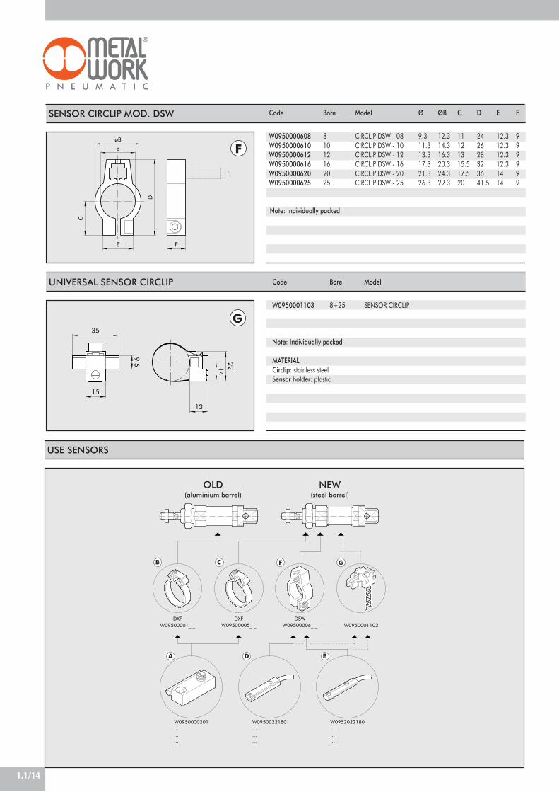
ROUND CYLINDER SERIES RNDCØ 32 TO 50 mm AND ACCESSORIES
Clean profile cylinders available in different versions:• configuration with or without magnet• single- and double-acting - single or through-rod• pneumatic cushioning on request• range of gaskets available in NBR, POLYURETHANE and FKM/FPM (for high temperatures).
Polyurethane NBR FKM/FPM Low Temperature
max 10 bar (max 1 MPa - 145 psi)–20°C to +80°C –20°C to +80°C –10°C to +150°C –35°C to +80°C
(non-magnetic cylinders) (non-magnetic cylinders) (non-magnetic cylinders)–20°C to +70°C –20°C to +70°C
(magnetic cylinders) (magnetic cylinders)Unlubricated air. Lubrication, if used, must be continuous
Ø 32; Ø 40; Ø 50Screwed heads
Double-acting, Double-acting through-rod, Double-acting cushioned, Double-acting through-rod cushioned,Single-acting, Single-acting through-rod, no-stick slip*
All versions come complete with magnet. Supplied without magnet on requestSingle-acting: for bores Ø32-50 strokes from 0 to 250 mmDouble-acting: for bores Ø32-50 strokes from 25 to 500 mm
Ø32 to Ø40: 0.4 bar - Ø50: 0.3 barSee GENERAL TECHNICAL DATA PAGE 1.1/06See GENERAL TECHNICAL DATA PAGE 1.1/05
! Maximum recommended strokes. Higher values can create operating problems*Using for speeds lower than 0.2m/s, to prevent surging.
For no-stick-slip versions use no-lubricated air only
TECHNICAL DATAOperating pressureTemperature range
FluidBoresDesignVersions
Magnet for sensorsStandard strokes !
Inrush pressureForces generated at 6 bar thrust/retractionWeights
COMPONENTS
! PISTON ROD: C45 steel or stainless steel, thick chromed
" PISTON ROD GASKET: polyurethane, NBR or FKM/FPM
# GUIDE BUSHING: steel strip with bronzeand PTFE insert
$ BARREL: drawn anodised aluminium alloy
% HALF-PISTON: self-lubricating techno-polymer with integrated cushioning olives
& MAGNET: in plastoferrite' PISTON GASKET: polyurethane, NBR or
FKM/FPM( ) HEAD: anodised aluminium alloy
2 94 5 63 8 71

DIMENSIONS OF STANDARD VERSIONS
CH
SW
1
1
109
110
111
112
113
M S P
F W N
V
D G O D
E
CH
2
R +
T
L +
I +
R +
DIMENSIONS OF THROUGH-ROD VERSIONS
1
1
SW
CH
115
114
104
1
R +
T +
W +I +
T
D S
E
M
VF
R +
PG O
W
V
F
CH
2
L ++
+ = ADD STROKE
+ = ADD STROKE++= ADD TWICE THE STROKE
Ø324050
DM30x1.5M38x1.5M45x1.5
EM8x1M10x1M12x1.5
F222432
Ø G303845
CH1101317
I96113120
L172198220
MM10x1.25M12x1.25M16x1.5
N141618
OG1/8G1/4G1/4
Ø P384657
R788996
Ø S121620
SW171924
T495762
CH2364354
V303538
W404550
Lower limit050100150200
Stroke< C !< C !< C !< C !< C !
Upper limit50100150200250
Ø 3296125154183212
Ø 40113145.5178210.5243
Ø 50120155.5191226.5262
Ø 32172201230259288
Ø 40198230.5263295.5328
Ø 50220255.5291326.5362
Ø 32127156185214243
Ø 40146178.5211243.5276
Ø 50158193.5229264.5300
For all the other values, see previous table, except for T and R which are both replaced by R1.
DIMENSIONS OF STANDARD DOUBLE-ACTING AND THROUGH-ROD
DIMENSIONS OF STANDARD SINGLE-ACTING AND THROUGH-RODI L R1
L1220251284
Ø 32220249278307336
Ø 40251283.5316348.5381
Ø 50284319.5355390.5426
L1
1.1/20

1.1/21
1
NOTES
KEY TO CODES
CYL 1 1 2
!104 SE axial coupling109 DEA110 DE
!111 SE112 DEM113 DEMA114 DEM through-rod115 DEMA through-rod
0
0 Standard " G No stick
slipS Non-
magnetic
3 2
324050
0 0 2 5
For the maximumsuppliable strokes,look at the technicaldata
C
A C45 chrome rod,aluminium piston rod
C C45 chrome rod,technopolymer
piston rodZ Stainless steel piston
rod and nutaluminium piston
X Stainless steel pistonrod and nut
technopolymer piston
P
DE: Double-acting (non-cushioned, not magnetic)DEM: Magnetic double-acting (non-cushioned)DEMA: Magnetic double-acting (cushioned)DEA: Cushioned double-acting (non-magnetic)SE: Single-acting (magnetic)
TYPE BORE STROKE
P polyurethaneN NBR
# V FKM/FPM# B low
temperature
# Only available for non-magnetic versions (S) and with aluminium piston (A or Z)" For speeds lower than 0.2m/s, to prevent surging. Use no-lubricated air only! Only available for versions with aluminium piston (A or Z)

1.1/22
B12
øM
F
L
B
A
C
DN
B C
A
M
G
I
EOH
N
C
D
L +
A +
B
F
RG
SW
M
I
H
B
D
F
øE
A
L +
C
Code
W0950322020W0950402020W0950502020
Ø
324050
Ø M
101216
C
202432
B
101216
A
202432
L
526283
F
404864
D
M10x1,25M12x1,25M16x1,5
FORK MODEL GK-M
HEAD LOCK RING MODEL G Ø
324050
A
M30x1.5M38x1.5M45x1.5
B
455058
C
789
Code
W0950320010W0950400010W0950500010
ACCESSORIES: FIXINGS
FOOT MODEL AC
COUNTER-HINGE MODEL BC
+ = ADD STROKE
Code
W0950320002W0950400002W0950500002
Ø
324050
A
124153160
B
506064
C
71010
D
456
E
142020
F
526070
G
799
H
141820
I
283040
L
150178190
M
668090
N
495870
O
283340
Weight [g]
104190296
Code
W0950320005W0950400005W0950500005
Ø
324050
A
405054
B
354045
C
243034
D
456
E
799
F
81010
G
121314
H
46.156.169.1
I
202836
L
127146158
M
6072.589
R
121314
SW
131719
Weight [g]
152262401
Note: Supplied with 2 screws
Note: Individually packed
Weight [g]
4656126
Weight [g]
92148340
+ = ADD STROKE
Note: Individually packed
Note: Individually packed
N
263240

1.1/23
1
SENSOR CIRCLIP
SENSOR
Bore
324050
Ø
364555
A
29.534.538.5
B
101010
Code
W0950000132W0950000140W0950000150
Codes
W0950000201W0950000222W0950000232
N.B.: For technical data on sensors, see page 1.1/12
5°
5°
SW4SW5
SW3
SW1
SW2B
D
A A øF
C
øE
ARTICULATED JOINT MODEL GA-K Code
W0950322030W0950402030W0950502030
Ø
324050
A
M10x1,25M12x1,25M16x1,5
B
202432
C
202032
D
7175103
Ø F
222232
SW1
121220
SW2
303041
SW3
303041
SW4
191930
SW5
171924
H7
CH
-0.1
2+
0
B1
F
L
D
C
A
øM
B
øG øG1
Code
W0950322025W0950402025W0950502025
Ø
324050
C
151722
B1
10,51215
L
576685
F
435064
B
141621
A
283242
D
M10x1,25M12x1,25M16x1,5
Ø G
1517,522
CH
171922
SPHERICAL JOINT MODEL GA-M Ø M
101216
ACCESSORIES: MAGNETIC SENSORS
Model
CIRCLIP DXF 36- 32CIRCLIP DXF 45- 40CIRCLIP DXF 52- 50
Description
REED SENSOR ACC. DSM2 - C525 HSE. HALL PNP SENSOR ACC. DSM3-N225E. HALL NPN SENSOR ACC. DSM3-M225
Weight [g]
78116226
Weight [g]
216220620
Note: Individually packed
Note: Individually packed
Ø E
444
9.1
11.5
25.534
17
A B
ø
ØG1
1°30
'1°
30'
CH
P
B
B
øD1
F
øD
øG
S1 S
A
AC
FLEXIBLE COLLAR - MODEL GA Code
W0950326021W0950406021W0950506021
Note: Individually packed.
Ø
324050
A
495979
B
364258
C
303644
ØD
111417
ØD1
6.58.510.5
F
M10x1.25M12x.125M16x1.5
ØG
39.54459
ØG1
171926
P
6.58.510.5
S
121520
S1
1013.515
Weight [g]
172286628
CH
131522
1.1/24
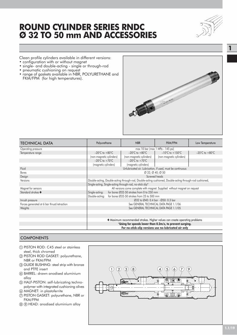
CARTRIDGE MICROCYLINDERSERIES CRTC, Ø 6-16 mm
Single-acting micro-cylinders with threaded body for fixingin small space or directly inside the machine body, owingto the external O-ring which ensures perfect seal.
ATTENTION: in case of cycles with high frequences it'sadvisable that the piston doesn't reach the end of thestroke during the rod coming out stage
NBR2 to 6 bar (0.2 to 0.6 Mpa)–10 to +80Lubricated or unlubricated air. Lubrication, if used, must be continuous6 ; 10 ; 165 ; 10 ; 15M5Single-actingMechanically edged
TECHNICAL DATAGasketsOperating pressureTemperature range °CFluidBores mmStrokes mmPortVersionsDesignSeal OR on the body (not included in the supply)
Weight [g]
COMPONENTS
! Nickel-plated brass body" NBR rubber piston rod gasket# AISI 303 steel piston/piston rod(for Ø 6 - Ø 10)# Brass piston (for Ø 16)$ Steel spring% Zinc-plated steel nut& Brass bushing' AISI 303 steel piston rod (for Ø 16)( Zinc-plated steel nut
267 345
1
8
Ø
61016
5143076
10163584
15194090
STROKE
Ø61016
7x19.5x1.516x1.5
OR

1.1/25
1
CH1
SW
CHN
S
A
HM
E B C
GF
L 1
L 2
L 3
L
K+
0.12
+0.
05M1
CARTRIDGE CYLINDERDIMENSIONS, Ø 6, 10, 16
KEY TO CODES
ASSEMBLY SEAT DIMENSIONS
Ø
61016
5 10 15
19.5 26.5 33.523 29.5 36.527 32 37
5 10 15
14.5 21.5 28.516 22.5 29.521 26 31
C
576
CH
91420
E
810.513
F
M3M4M5
G
8.51219
H
M10x1M15x1.5M22x1.5
M
M5M5M5
S
345
SW
141927
Ø
61016
5 10 15
5 5 56 6 67 7 7
5 10 15
10 17 2411 17 2415 20 25
5 10 15
12 19 2613 19 2617 21 27
5 10 15
16 24 3120 26 3426 31 36
ORDERING CODESCodesW1000060005W1000060010W1000060015W1000100005W1000100010W1000100015W1000160005W1000160010W1000160015
DescriptionCYL. CRTC-006-0005-S000-00CYL. CRTC-006-0010-S000-00CYL. CRTC-006-0015-S000-00CYL. CRTC-010-0005-S000-00CYL. CRTC-010-0010-S000-00CYL. CRTC-010-0015-S000-00CYL. CRTC-016-0005-S000-00CYL. CRTC-016-0010-S000-00CYL. CRTC-016-0015-S000-00
CYL
FURTHER DESCRIPTIONSSPECIAL DESIGN
= NOT ENVISAGED
0 0 0 0C R T C
CARTRIDGEMICROCYLINDER
0 1 0
006 010 016
0 0 1 0
000500100015
S 0 0 0
Single-acting
retractedpiston
rod
TYPE DIAMETER STROKE TYPE FURTHERDESCRIPTION
SPECIALDESIGN
L Stroke L1 L2 L3
A Stroke B Stroke CH1
5.578
N
2.424
Stroke StrokeStroke K
8.51219
M1
M10x1M15x1.5M22x1.5

1.1/26
SHORT-STROKE CYLINDERSERIES SSCY, Ø 12-100 mmAND ACCESSORIES
Compact cylinders suitable for installation in limited spaces:• configuration with or without magnet• single or double-acting - single or through-rod• anti-rotation version and with built-in fixings• possible choice of NBR, POLYURETHANE or FKM/FPM gaskets• special design on request.
TECHNICAL DATAOperating pressureTemperature rangeFluidBoresDesignStandard strokes !
Versions
Magnet for sensorsInrush pressureForces generated at 6 bar thrust/retractionWeight
COMPONENTS
! PISTON ROD: C45 steel or stainless steel, thick chromed" HEAD: ! 12 to 25 nichel-plated brass
! 32 to 100 anodised aluminium# PISTON ROD GASKET:
! 12 to 63 SFR (PARKER PRADIFA) NBR or FKM/FPM! 80 to 100 polyurethane (PARKER PRADIFA), NBR or FKM/FPM
$ GUIDE BUSHING: steel strip with bronze and PTFE insert% BARREL: drawn anodised aluminium alloy& HALF-PISTON:
! 12 to 63 acetal resin! 80 to 100 in aluminium with PTFE guide pad
' PISTON GASKET:! 12 to 63 polyurethane (PARKER PRADIFA), NBR or FKM/FPM! 80 to 100 SFR (PARKER PRADIFA) NBR or FKM/FPM
( MAGNET: ! 12 to 25 in neodymium - ! 32 to 100 in plasto-ferrite
) Static O-rings: NBR or FKM/FPM
54 96 72 831
Polyurethane NBR FKM/FPM Low Temperature
max 10 bar (max 1 MPa - 145 psi)–10°C to +80°C –10°C to +80°C –10°C to +150°C (non-magnetic cylinders) –35°C to +80°C
Unlubricated air. Lubrication, if used, must be continuousØ 12 ; Ø 16 ; Ø 20 ; Ø 25 ; Ø 32 ; Ø 40 ; Ø 50 ; Ø 63 ; Ø 80 ; Ø 100
With profileDouble acting: Ø 12 to Ø 25, stroke 5 to 50 mm
Ø 32 to Ø 40, stroke 5 to 70 mmØ 50 to Ø 63, stroke 5 to 110 mmØ 80 to Ø 100, stroke 5 to 150 mm
Single-acting: Ø 12 to Ø 25, stroke 5 to 25 mmØ 32 to Ø 63, stroke 5 to 50 mm
Anti-rotation: Ø 12 to Ø 63, stroke 5 to 120 mmØ 80 to Ø 100, stroke 5 to 150 mm
Perforated through-rod: Ø 20 to Ø 40, stroke 5 to 100 mmØ 50 to Ø 63, stroke 5 to 130 mmØ 80 to Ø 100, stroke 5 to 165 mm
Double-acting, Double-acting through-rod, Single-acting retracted piston rod, Single acting extended piston rod, Single-acting through-rod, Perforated through-rod, Anti-rotation, Oscillating male, Oscillating female, no-stick slip*
All versions come complete with magnet. Supplied without magnet on requestØ 12 to Ø 32: 0.6 bar - Ø 40 to Ø 100: 0.4 barSee GENERAL TECHNICAL DATA PAGE 1.1/04See GENERAL TECHNICAL DATA PAGE 1.1/06
! Maximum recommended strokes. Higher values can create operating problems*Using for speeds lower than 0.2m/s, to prevent surging.
For no-stick-slip versions use no-lubricated air only

1.1/27
1
DIMENSIONS STANDARD VERSIONS
øO
CH
1210
212
213
208
HH 1
øSQQ
øS
N+G +G+
J
K V
øO
LL
TM
øC øC1
E
A
R
B
F
U
P
D
DIMENSIONS OF DOUBLE ACTING
DIMENSIONS OF SINGLE-ACTING, RETRACTED PISTON ROD
Ø121620253240506380100
A23.52832374554.56680100124
B132022263240506282103
øC681010121216162025
øC1
5.57.599111115151924
D28333747.55662.77388110134
E262832394854.56680100124
F11111118181818232626
G32.53332333739.539.5425764
G1
---
36.540.844.746.248.767.274.7
H6.56.76.58.5101011121415
H1
10.510.510.58.5101011121415
J3.73.74.64.65.55.56.69911
K667.57.5101011151518
L3.73.74.64.65.75.76.89911
M7101010151518181820
N3837.536.542.548.353.253.257.775.284.3
øO---
20253035354456
PM3M5M5M5M6M6M8M8M10M12
QM5M5M5G1/8G1/8G1/8G1/8G1/8G1/4G1/4
R -2022283640506282103
øS88815151515151919
CH5788101013131722
T22222.52.53.53.545
U9.5101114182025314151.5
V16.51921283235.540486072
Ø1216202532
40
50
63
stroke5÷255÷255÷255÷255÷25>25÷505÷25>25÷505÷25>25÷505÷25>25÷50
A23.528323745
54.5
66
80
B1320222632
40
50
62
øC68101012
12
16
16
øC1
5.57.59911
11
15
15
D28333747.556
62.7
73
88
E2628323948
54.5
66
80
F1111111818
18
18
23
G32.5333233374539.547.539.547.54250
G1
---
36.540.848.844.752.746.254.248.756.7
H6.56.76.58.510
10
11
12
H1
10.510.510.58.510
10
11
12
J3.73.74.64.65.5
5.5
6.6
9
K667.57.510
10
11
15
L3.73.74.64.65.7
5.7
6.8
9
M710101015
15
18
18
N3837.536.542.548.356.353.261.253.261.257.765.7
øO---
2025
30
35
35
PM3M5M5M5M6
M6
M8
M8
QM5M5M5G1/8G1/8
G1/8
G1/8
G1/8
R-
20222836
40
50
62
øS8881515
15
15
15
CH578810
10
13
13
T22222.5
2.5
3.5
3.5
U9.510111418
20
25
31
V16.519212832
35.5
40
48
+ = ADD THE STROKE
FIXING METHOD FOR SSC CYLINDERS
Fix directly from above using long through-screws or tie rods. Non-magnetic stainlesssteel must be used (e.g. AISI 304).

1.1/28
DIMENSIONS OF SINGLE-ACTING EXTENDED PISTON ROD
øO
1
211
CH
209
G+
G +
N++
HH 1
øSøS
L L
U
øC1
MT
øO
øC
P ED
R
A
V
J
K
B
F
DIMENSIONS OF Ø 12 ANTI-ROTATION
215
217
CH
øCC
GG
H H1
øC1
øC
ED
F
B
A
V
øS
U
J
øDD
BB
N+AA
L
G+
Q
Z2
FF
Z1
+ = ADD THE STROKE++= ADD TWICE THE STROKE
Ø12
A23.5
B13
øC6
ØC1
5.5D28
E26
F11
G32.5
H6.5
H1
10.5JM6
L12
N38
Z1
16Z2
11QM5
øS8
U9.5
V16.5
AA8
BB3.5
øCC6
øDD3.5
FFM3
øGG4
+ = ADD THE STROKE
Ø1216202532
40
50
63
stroke5÷255÷255÷255÷255÷25>25÷505÷25>25÷505÷25>25÷505÷25>25÷50
A23.528323745
54.5
66
80
B1320222632
40
50
62
øC68101012
12
16
16
øC1
5.57.59911
11
15
15
D28333747.556
62.7
73
88
E2628323948
54.5
66
80
F1111111818
18
18
23
G32.5333233374539.547.539.547.54250
G1
---
36.540.848.844.752.746.254.248.756.7
H6.56.76.58.510
10
11
12
H1
10.510.510.58.510
10
11
12
J3.73.74.64.65.5
5.5
6.6
9
K667.57.510
10
11
15
L3.73.74.64.65.7
5.7
6.8
9
M710101015
15
18
18
N3837.536.542.548.356.353.261.253.261.257.765.7
øO---
2025
30
35
35
PM3M5M5M5M6
M6
M8
M8
QM5M5M5G1/8G1/8
G1/8
G1/8
G1/8
R-
20222836
40
50
62
øS8881515
15
15
15
CH578810
10
13
13
T22222.5
2.5
3.5
3.5
U9.510111418
20
25
31
V16.519212832
35.5
40
48

1.1/29
1
CH
1
215
217
G+G +
FF øGG
AA
BB
øDD
øCC
øCøC1
øEE
øJøK
Q
L
E
D
R
Z 1
ABZ2
V
L
U
F
øS
H 1H
øON
+
DIMENSIONS OF Ø 16 TO Ø 100 ANTI-ROTATION
+ = ADD THE STROKE
Ø1620253240506380100
A2832374554.56680100124
B2022263240506282103
øC81010121216162025
øC1
7.599111115151924
D333747.55662.77388110134
E2832394854.56680100124
F111118181818232626
G3332333739.539.5425764
G1
--
36.540.844.746.248.767.274.7
H6.76.58.5101011121415
H1
10.510.58.5101011121415
J3.74.64.65.55.56.69911
K67.57.5101011151518
L3.74.64.65.75.76.89911
N37.536.542.548.353.253.257.775.284.3
Z1
202222263443557094
Z2
151822263443557094
QM5M5G1/8G1/8G1/8G1/8G1/8G1/4G1/4
R2022283640506282103
øS8815151515151919
CH788101013131722
U101114182025314151.5
Ø1620253240506380100
V1921283235.540486072
AA888101012121417
BB3.555667999
øCC67.57.5101011141414
øDD3.54.54.55.55.56.5999
øEE67.58101011151518
FFM3M4M4M5M5M6M6M8M8
øGG4668810101212
øO--
20253035354456

1.1/30
1
2
CH
3
218
223
214
XG +
U
VK
ED
R
J
B
F
A
øO P
T
X+N ++
øC
L L
HøS
H 1
QQøS
øC1
=
M
G +
ød
=
DIMENSIONS OF THROUGH-ROD
+ = ADD THE STROKE++= ADD TWICE THE STROKE
Ø121620253240506380100
A23.52832374554.56680100124
B132022263240506282103
øC681010121216162025
øC1
5.57.599111115151924
D28333747.55662.77388110134
E262832394854.56680100124
F11111118181818232626
G2
36.736.83635.73739.539.5425764
G3
---
42.744.549.952.955.477.485.4
H10.510.510.58.5101011121415
H1
10.510.510.58.5101011121415
J3.73.74.64.65.55.56.69911
K667.57.5101011151518
L3.73.74.64.65.75.76.89911
N1
47.745.845.054.759.566.966.973.493.4104.6
øO---
20253035354456
PM3M5M5M5M6M6M8M8M10M12
QM5M5M5G1/8G1/8G1/8G1/8G1/8G1/4G1/4
R -2022283640506282103
øS88815151515151919
CH5788101013131722
U9.5101114182025314151.5
ød** - -1.51.52.52.52.5456
M7101010151518181820
T22222.52.53.53.545
V16.51921283235.540486072
X*5.54.54.567.58.57989.6
DIMENSION OF DOUBLE ACTING THROUGH-ROD AND PERFORATED THROUGH-ROD
Ø1216202532
40
50
63
stroke5÷255÷255÷255÷255÷25>25÷505÷25>25÷505÷25>25÷505÷25>25÷50
A23.528323745
54.5
66
80
B1320222632
40
50
62
øC68101012
12
16
16
øC1
5.57.59911
11
15
15
D28333747.556
62.7
73
88
E2628323948
54.5
66
80
F1111111818
18
18
23
G2
36.736.83635.7374539.547.539.547.54250
G3
---
42.744.552.549.957.952.960.955.463.4
H10.510.510.58.510
10
11
12
H1
10.510.510.58.510
10
11
12
J3.73.74.64.65.5
5.5
6.6
9
K667.57.510
10
11
15
L3.73.74.64.65.7
5.7
6.8
9
M710101015
15
18
18
N1
47.745.845.057.759.567.566.974.966.974.973.481.4
øO---
2025
30
35
35
PM3M5M5M5M6
M6
M8
M8
QM5M5M5G1/8G1/8
G1/8
G1/8
G1/8
R-
20222836
40
50
62
øS8881515
15
15
15
CH578810
10
13
13
T22222.5
2.5
3.5
3.5
U9.510111418
20
25
31
V16.519212832
35.5
40
48
DIMENSION OF SINGLE-ACTING THROUGH-RODX*5.54.54.567.57.58.58.57799
*for Ø12, Ø16, Ø20: (N1++) = (G2+) + (X) + (X+)**column for perforated through-rod only
*for Ø12, Ø16, Ø20: (N1++) = (G2+) + (X) + (X+)

1.1/31
1
R
1
G +
G +
N +
H 8
H 6
D2
S 1
S 2
R
1
G +
G +
N +
H 8
H 6
D2
S 1
DIMENSIONS: SAME AS 221 VERSION(MALE HINGE MOD. BA) Ø
32405063
stroke
5÷705÷705÷1105÷110
D2
10121216
G
5964.566.574
G1
62.869.773.280.7
H6
22252732
H8
10101212
N
70.378.280.289.7
R
11131317
S1
26283240
+= ADD THE STROKE
+= ADD THE STROKE
DIMENSIONS: SAME AS 222 VERSION(FEMALE HINGE MOD. B) Ø
32405063
stroke
5÷705÷705÷1105÷110
D2
10121216
G
5964.566.574
G1
62.869.773.280.7
H6
22252732
H8
10101212
N
70.378.280.289.7
R
11131317
S1
26283240
S2
45526070
Note: For other dimensions, refer to the standard version.
Note: For other dimensions, refer to the standard version.
KEY TO CODES
CYL 2 1 2
! 208 Single-acting retracted rod,non-magnetic
! 209 Single-acting extended rod,non-magnetic
! 210 Single-acting, retracted rod! 211 Single acting, extended rod
212 Double acting, magnetic213 Double acting, non-magnetic214 Double acting, through-rod
! 215 Single-acting,retracted, anti-rotation
217 Double acting, anti-rotation" 218 Double acting,
perforated through-rod221 Oscillating male hinge
(up to Ø 63 only)222 Oscillating female hinge
(up to Ø 63 only)! 223 Single-acting, through-rod
4 0
121620253240506380
# 100
0 0 1 0
For the maximumsuppliablestrokes, look atthe technical data
C
BORE STROKE
0
0 MagneticS Non-
magnetic$ G No stick slip
P
P polyurethaneN NBR
% V FKM/FPM% B low
temperature
# In the code of cylinder with letter in fourth position Ø 100 becomes A1! Available up to Ø63" Available from Ø20% Only available for non-magnetic versions (S) and with aluminium piston (A or Z)$ For speeds lower than 0.2m/s, to prevent surging. Use no-lubricated air only
A C45 chrome rod,aluminium piston rod
Ø 12÷63 mmC C45 chrome rod,
technopolymerpiston rod
(standard Ø 80÷100 mm)Z Stainless steel piston
rod and nutaluminium piston
Ø 12÷63 mmX Stainless steel piston
rod and nuttechnopolymer piston
(standard Ø 80÷100 mm)
TYPE

1.1/32
9
1
2
3
4
5
6
7
8
1011 12 13
141516
CH
øD
B Cød
Ø
121620253240506380100
Ø D
M6M8M8M10x1.25M10x1.25M12x1.25M16x1.5M16x1.5M20x1.5M20x1.5
Ø d
M3M5M5M5M6M6M8M8M10M12
B
16202022222432324040
C
6999121215151518
CH
466771013131717
Code
219001200219001600219001600219002500219003200219004000219005000219005000219008000219010000
Weight [g]
388121414202096102
TypeComplete polyurethane front head kitComplete NBR front head kitComplete NBR rear head kitComplete polyurethane piston kitComplete NBR piston kitComplete set of polyurethane gasketsComplete set of NBR gasketsComplete polyurethane front+rear head kit + pistonComplete NBR front+rear head kit + pistonMagnet
Parts1-2-3-4-5-61-2-3-4-5-67-8-9-1011-12-13-14-1511-12-13-14-152-4-5-8-10-13-152-4-5-8-10-13-151-2-3-4-5-6-7-8-9-10-11-12-13-14-151-2-3-4-5-6-7-8-9-10-11-12-13-14-1516
BoresØ 12÷100Ø 12÷100Ø 12÷100Ø 12÷100Ø 12÷100Ø 12÷100Ø 12÷100Ø 12÷100Ø 12÷100Ø 12÷100
Code009 . . . 0010009 . . . 0011009 . . . 0015009 . . . 0021009 . . . 0023009 . . . 0005009 . . . 0006009 . . . 0031009 . . . 0033009 . . . 0001
DIMENSIONS OF MALE NIPPLE FOR PISTON ROD
SPARES FOR SSCY

1.1/33
1
24V DC
blue
brown
24V AC
+
-
blue
brown ~
~
brown
-
black
brown
black
+
+
-
blue
blue
Version NPN
Version PNP
26
11
23
10
28
DC
AC
PROXIMITY SENSORS – TECHNICAL DATA
TypeContactMax AC/DC voltageMax current at 25°CPower with inductive loadPower with resistive loadSwitch-on timeSwitch-off timeSwitch-on pointSwitch-off pointOperating lifeContact resistanceCable lengthCable cross sectionCable materialCircuit
VmAVA
Wattm secm secGaussGauss
–
mmm2
REED+VARISTOR+LED 2 wiresREED+VARISTOR+LED NO3 to 48 (DC): 3 to 110 (AC)
3008
150.50.111060
107 impulses0.12.5
0.35Soft PVC
HALL VERSION PNP/NPN 3 wiresHALL EFFECT NO PNP/NPN
6-24 V DC250
–6
0.83
158
109 impulses–
2.50.35
Soft PVC
ACCESSORIES: MAGNETIC SENSORS
Version
Reed connector+ bracket - CBHall PNP connector+ bracket - CB
Bore
12-100
12-100
Model
REED SENSOR DCB 2C-425
SENSOR AND HALL PNP DCB3-N225
Code
W0950000252
W0950000253

1.1/34
COMPACT CYLINDERSSERIES “CMPC” Ø 12÷100
Compact cylinder series CMPC available in numerousversions to meet a full range of requirements:• With or without magnet• Single-acting extended rod, retracted or through-rod• Dual-acting non-rotating and dual-acting through-rodversions• Tandem with two, three or four stages• Multi-position with two and three stages• Fixing centre distances to ISO 15552 from Ø 32 toØ 100 and from Ø 20 to Ø 100 complying with Frenchstandard NFE 49-004-1 and 2 (UNITOP). Ø 12 and Ø 16have centre distances compatible with trade cylinders.The special profile and outer heads locked onto the jacketby screws ensure optimal guiding of the cylinder andmultiple fixing options with a wide range of mountings.To determine the position in the relevant cylinder slots, itis possible to mount retracting magnetic limit switches.Available also in a version having FKM/FPM gaskets (forhigh temperature) from Ø20 to Ø100.
POLYURETHANE FKM/FPM
max 10 bar (max 1 MPa-145 psi)–10°C ÷ +60°C (ø20÷63) –10°C ÷ +150° (non-magnetic cylinders)
–10°C ÷ +80°C (ø80÷100)Unlubricated air. Lubrication, if used, must be continuous.
Ø12, Ø16; interchangeable with similar productsØ 30, Ø 40, Ø 50, Ø 63, Ø 80 and Ø 100 with ISO 15552 fixing centre distances.
Ø 20, Ø 25, Ø 32, Ø 40, Ø 50, Ø 63, Ø 80 and Ø 100 with NFE 49-004-1 and 2 fixing centre distances.With profile, heads with screws
Double-acting, Single-acting extended or retracted rod, Through-rod, Through-rod perforated, Single-acting through-rod,Through-rod non-rotating, no-stick slip*
All versions are available with male or female piston rod.All versions come complete with magnet. Supplied without magnet on request.
As requiredFor correct operation, it is advisable to use 50 m filtered air
Ø 12 to Ø 32: 0.6 bar - Ø 40 to Ø 100: 0.4 barSee GENERAL TECHNICAL DATA PAGE 1.1/05See GENERAL TECHNICAL DATA PAGE 1.1/06
*Using for speeds lower than 0.2m/s, to prevent surging.For no-stick-slip versions use no-lubricated air only
TECHNICAL DATAOperating pressureTemperature rangeFluidBores mm
mmmm
DesignVersions
Magnet for sensorsInrush pressureNotesInrush pressureForces generated at 6 bar thrust/retractionWeights
COMPONENTS Ø 12÷25
! PISTON ROD: stainless steel, thick chromed" HEAD: extruded anodised aluminium alloy# BARREL: drawn anodised and calibrated aluminium alloy$ PISTON GASKET: polyurethane or FKM/FPM% MAGNET: neodymium-plastic& PISTON ROD GASKET: polyurethane or FKM/FPM' GUIDE BUSHING: steel strip with bronze and PTFE insert.( STATIC O-RINGS: NBR or FKM/FPM) SECURING SCREWS: zinc-plated steel
2 3 4 56 7 8
9
1

1.1/35
1
6 5 87 2 3 4
9
1
3
3
4
5
6
5
1
7
2
COMPONENTS Ø 32÷100
! PISTON ROD: C45 steel or stainless steel, thick chromed" HEAD: extruded anodised aluminium alloy# JACKET: drawn anodised and calibrated aluminium alloy$ PISTON GASKET: polyurethane or FKM/FPM% MAGNET: Ø 12÷32 neodymium-plastic
Ø 40÷100 plastoferrite& PISTON ROD GASKET: polyurethane or FKM/FPM' GUIDE BUSHING: steel strip with bronze and PTFE insert.( STATIC O-rings: NBR or FKM/FPM) SECURING SCREWS: zinc-plated steel
TECHNICAL DATA
! Compact cylinder available with two separate fixing centre distances• Ø 32÷100 to ISO 15552• Ø 20÷100 to NFE 49-004-1 and 2
" Pre-wired retracting sensor with or without connector# Plastic strip to keep out dirt and/or protect the sensor wire cod. W0950000160$ Ball-and-socket joint code W095… 2030% Example of cylinder mounting with feet code W095… 6001
All mountings come complete with cylinder assembly screws& Sensor slot' Piston rod with male or female thread as required

1.1/36
FORCE OF SPRINGS IN SINGLE-ACTING CYLINDERS (THEORETICAL)
BoreMin. load (N)Max. load (N)
Ø 124.409.80
Ø 164.9014.20
Ø 208.4020.90
Ø 2513.9033.20
Ø 3219.0035.90
Ø 4024.8053.70
Ø 5036.3062.20
Ø 6350.2082.30
Ø 8077.60118.90
Ø 100131.80183.30
STROKES FOR COMPACT CYLINDERS
Standard stroke for single-acting cylindersØ 12 ! 10 mmØ 16; Ø 100 ! 25 mm
Standard stroke for other typesØ 12; Ø 16 ! from 5 to 40 mmØ 20; Ø 25 ! from 5 to 50 mmØ 32÷Ø 100 ! from 5 to 80 mm
Max. recommended strokes for other typesØ 12÷Ø 25 ! 200 mmØ 32; Ø 40 ! 300 mmØ 50; Ø 63 ! 400 mmØ 80; Ø 100 ! 500 mm
Max. recommended strokes for non-rotating cylindersØ 12÷Ø 63 ! 120 mmØ 80; Ø 100 ! 150 mm
B
C D E
A
Max recommended strokes for through-rod perforatedØ 20÷Ø 40 ! from 5 to 80 mmØ 50; Ø 63 ! from 5 to 100 mmØ 80; Ø 100 ! from 5 to 160 mm
COMPACT CYLINDER FIXING OPTIONS
Fixing to structural work with a through screw, using the thread in the heads (Fig. A)Direct fixing from above using long through screws or tie rods (Fig. B). Non-magnetic stainless steel must be used (e.g. AISI 304)Fixing with feet; the ordering code covers the supply of one foot and two screws for fixing to the cylinder (Fig. C).Fixing with a flange mounted on the front or rear head; the ordering code covers the supply of a flange and four screws for fixingto the cylinder (Fig. D).Fixing with articulated hinge to compensate for slight system misalignment and turn freely (Fig. E).The ordering code covers the supply of a hinge and four screws for fixing to the cylinder.

1.1/37
1VALVE ASSEMBLY ON CYLINDER
D
AC
B
With this type of cylinder, thevalves (D) can be mounteddirectly using the retractingsensor slot, without requiringthe use of intermediate brackets.This can be done using thespecial plates (A) which comewith both M3 and M4 threads,and screws (B) of the size, typeand quantity shown in the tablebelow.The plates are suppliedcomplete with 2 stud pins, oneM3 and one M4 (C).After the valve centre distanceand the position of the valvehave been determined, theplates can be secured to thecylinder. A “position memory”will be created to facilitatesubsequent maintenance on thevalve.
Type of valveto mount (D)
MACH 11SERIE 70 1/8SERIE 70 1/4
Fixingplate (A)
cod. 0950003000n. 2n. 2n. 2
Position memory:grub screw (C)
to be usedM4M3M3
Screw (B) forconnection to the cylinder
(one per plate)M3x16 UNI 5931 (DIN 912)M4x25 UNI 5931 (DIN 912)M4x30 UNI 5931 (DIN 912)
Washer (B)(one per screw)
A3.2 UNI 1751 (DIN 127A)—
A4.3 UNI 1751 (DIN 127A)
MAXIMUM LOADS FOR NON-ROTATING VERSION
TRANSVERSAL FORCEFOR NON-ROTATING
TRANSVERSAL FORCE FORNON-ROTATING THROUGH-ROD
TORQUE DEPENDINGON STROKE
ø32
ø12-16
ø50-63
ø80ø100
ø40
ø20-25
1008020 40 60 12000
L (mm)
240
220
180
100
120
140
160
200
20
40
60
80
F (N
)
FL M
t
ø63
ø100
ø80
ø32
ø12-16
ø50
ø40
ø20ø25
Mt (
Nm
)
Corsa (mm)
00 1401201008020 40 60
2
4
6
8
10
12
14
16
18
20
ø20-25
ø40
ø50-63
ø32
ø80-100
L (mm)0 8020 40 60 120100
F (N
)
180
100
120
140
160
200
20
40
60
80
0
ø12-16
FL
Stroke (mm)

1.1/38
CH1
R
S
S1+
CH1
R
S S1+
Ø 12Ø 16Ø 20Ø 25
A292936.540.5
B18182226
ØC681010
CH5788
CH110131717
D303037.541.5
ØE H96666
F4444
G38383839.5
H8888
H130303031.5
L18.518.518.519
M8101212
N42.542.542.545
OM4M4M5M5
ØO13.23.24.24.2
PM3M4M5M5
QM5M5M5M5
RM6M8M10x1.25M10x1.25
S16202222
S14.54.54.55.5
Ø 32Ø 40Ø 50Ø 63Ø 80Ø 100
A47566780102123
BB2–––131721
ØC121216162025
CH101013131722
CH1171719192430
D48.557.56982105126
ØE H9666888
F444444
G44.545.545.5505666.5
H7.57.57.57.58.510.5
H137383842.547.556
L44.54.55.55.55.5
M141416162024
N50.5525357.56476.5
ISOM6M6M8M8M10M10
UNITOPM6M6M8M10M10M10
ISO5.25.26.26.28.58.5
UNITOP5.25.26.28.58.58.5
PM6M6M8M8M10M12
QG1/8G1/8G1/8G1/8G1/8G1/4
RM10x1.25M10x1.25M12x1.25M12x1.25M16x1.5M20x1.5
S222224243240
S166.57.57.5810
ISO32.53846.556.57289
+0.1 –0.4
UNITOP3242506282103
+0.4 –0.1
O ØO1
CH1
S1+S
R
NORMA
UNITOPUNITOP
1
CH
233-243
230-240
234-244
P
Q
O
L
øO1
G+H1+
H
øEøC
N+
F
B
B
A
A D
M
1
1
7
8
234-244254-264
230-240250-260
233-243253-263
øO1
Q
B A D
H
G+
H1+ B
A
O
N+
PøC
F
øE
CH
M
L
B2
+ = ADD THE STROKE1 = SENSOR SLOT7 = ONLY FOR Ø63÷1008 = SEAT FOR DIN 7984 SCREWS
+ = ADD THE STROKE1 = SENSOR SLOT
S1+
CH1
S
RDIMENSIONS OF DOUBLE-ACTING Ø 32÷100 AND SINGLE-ACTING Ø 32÷100
DIMENSIONS OF DOUBLE-ACTING Ø 12÷25 AND SINGLE-ACTING Ø 12÷25
SE-DE MALE PISTON ROD
SE EXTENDED PISTON ROD
SE MALE EXTENDED PISTON ROD
SE-DE MALE PISTON ROD
SE EXTENDED PISTON ROD
SE MALE EXTENDED PISTON ROD
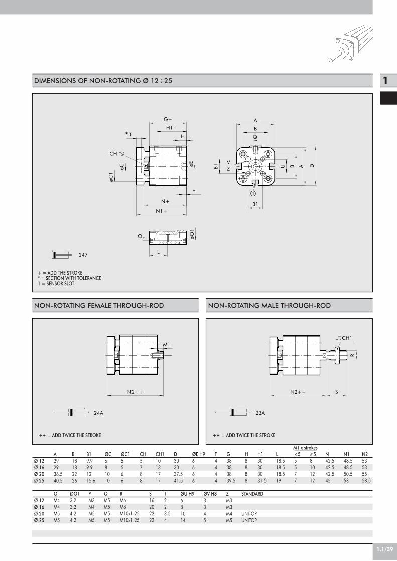
1.1/39
1
1
CH
VZ
*
247
øO1
O
L
G+
H1+
H
øC1
T
øC
N+
N1+
DBUB1 A
B
Q
B1
FøE
A
24A
N2++
M1CH1
23A
N2++ S
R
DIMENSIONS OF NON-ROTATING Ø 12÷25
NON-ROTATING FEMALE THROUGH-ROD NON-ROTATING MALE THROUGH-ROD
Ø 12Ø 16Ø 20Ø 25
A292936.540.5
M1 x strokesB18182226
B19.99.91215.6
ØC681010
ØC15566
CH5788
CH110131717
D303037.541.5
ØE H96666
F4444
G38383839.5
H8888
H130303031.5
L18.518.518.519
<55577
!58101212
N42.542.542.545
N148.548.550.553
N253535558.5
OM4M4M5M5
ØO13.23.24.24.2
PM3M4M5M5
QM5M5M5M5
RM6M8M10x1.25M10x1.25
S16202222
T223.54
ØU H9681014
ØV H83345
ZM3M3M4M5
Ø 12Ø 16Ø 20Ø 25
+ = ADD THE STROKE* = SECTION WITH TOLERANCE1 = SENSOR SLOT
STANDARD
UNITOPUNITOP
++ = ADD TWICE THE STROKE ++ = ADD TWICE THE STROKE
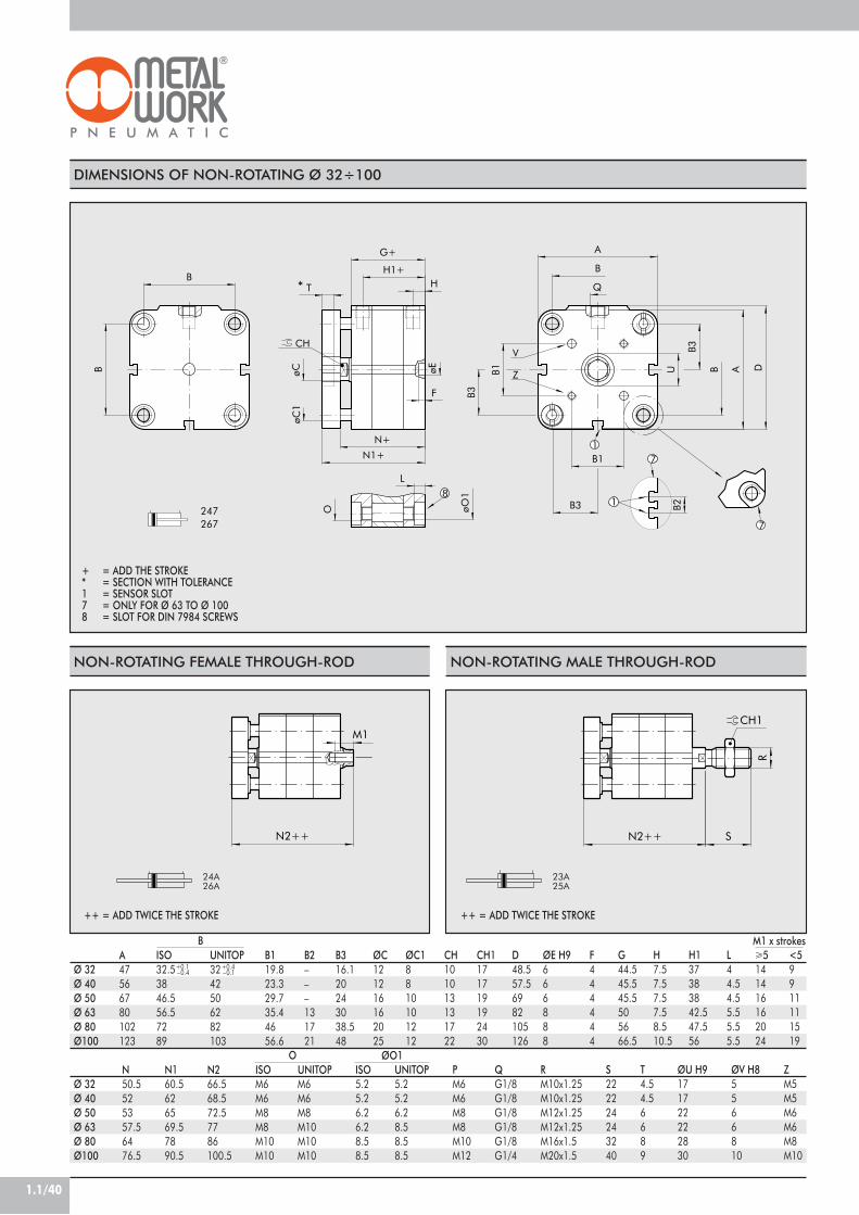
1.1/40
17
1
7
8
247267
V
Z
CH
*
B2
B1
B1
A
Q
B3
B3
B
U
B3
B A D
T
G+
H
O
L
H1+
N1+
N+
øC øE
øC1
F
øO1
B
B
24A
N2++
M1CH1
23A
N2++ S
R
DIMENSIONS OF NON-ROTATING Ø 32÷100
NON-ROTATING FEMALE THROUGH-ROD NON-ROTATING MALE THROUGH-ROD
Ø 32Ø 40Ø 50Ø 63Ø 80Ø100
A47566780102123
M1 x strokes
N50.5525357.56476.5
Ø 32Ø 40Ø 50Ø 63Ø 80Ø100
+ = ADD THE STROKE* = SECTION WITH TOLERANCE1 = SENSOR SLOT7 = ONLY FOR Ø 63 TO Ø 1008 = SLOT FOR DIN 7984 SCREWS
ISO32.53846.556.57289
+0.1 –0.4
UNITOP3242506282103
+0.4 –0.1
B119.823.329.735.44656.6
B2–––131721
ØC121216162025
ØC18810101212
CH101013131722
CH1171719192430
D48.557.56982105126
ØE H9666888
F444444
G44.545.545.5505666.5
H7.57.57.57.58.510.5
H137383842.547.556
L44.54.55.55.55.5
!5141416162024
<59911111519
B
N160.5626569.57890.5
N266.568.572.57786100.5
ISOM6M6M8M8M10M10
UNITOPM6M6M8M10M10M10
ISO5.25.26.26.28.58.5
UNITOP5.25.26.28.58.58.5
PM6M6M8M8M10M12
QG1/8G1/8G1/8G1/8G1/8G1/4
RM10x1.25M10x1.25M12x1.25M12x1.25M16x1.5M20x1.5
S222224243240
T4.54.56689
ØU H9171722222830
ØV H85566810
ZM5M5M6M6M8M10
O ØO1
++ = ADD TWICE THE STROKE ++ = ADD TWICE THE STROKE
24A26A
23A25A
B316.120243038.548

1.1/41
1
S1+
DIMENSIONS OF THROUGH-ROD Ø 32÷100
17
1
8232-242252-262
231-241251-261
235-245255-265
236-246256-266
CH1
P1
S N2++
R
N2++
øO1
L
B2
M1
H1+
CH
øC P
A
B
DAB
Q
M
G+
O
P2M
IN
N+
H
DIMENSIONS OF THROUGH-ROD Ø 12÷25
1C
H
232-242
231-241
235-245
236-246
CH1
N2++
G+H1+
H
M1
PøC
A
B
Q
B
O øO1
L
A D
N+
MS N2++
R
P2M
IN
P1
Ø 12Ø 16Ø 20*Ø 25**Built to UNITOP
A292936.540.5
B18182226
ØC681010
CH5788
CH110131717
D303037.541.5
G38383839.5
H8888
H130303031.5
L18.518.518.519
M8101212
Ø 32Ø 40Ø 50Ø 63Ø 80Ø 100
A47566780102123
BB2–––131721
ØC121216162025
CH101013131722
CH1171719192430
D48.557.56982105126
G44.545.545.5505666.5
H7.57.57.57.58.510.5
H13738384247.556
L44.54.55.55.55.5
M141416162024
ISOM6M6M8M8M10M10
UNITOPM6M6M8M10M10M10
ISO5.25.26.26.28.58.5
UNITOP5.25.26.28.58.58.5
PM6M6M8M8M10M12
QG1/8G1/8G1/8G1/8G1/8G1/4
RM10x1.25M10x1.25M12x1.25M12x1.25M16x1.5M20x1.5
S222224243240
ISO32.53846.556.57289
+0.1 –0.4
UNITOP3242506282103
+0.4 –0.1
O ØO1
<55577
!58101212
N42.542.542.545
N247474750.5
OM4M4M5M5
ØO13.23.24.24.2
PM3M4M5M5
QM5M5M5M5
RM6M8M10x1.25M10x1.25
S16202222
M1xstrokes
! 5141416162024
"59911111519
N50.5525357.56476.5
N256.558.560.5657286.5
M1xstrokes
+ = ADD THE STROKE++ = ADD TWICE THE STROKE
+ = ADD THE STROKE++ = ADD TWICE THE STROKE1 = SENSOR SLOT
P1––––1/81/4
P22.52.54456
P1––––
P2––1.51.5
SE-DE MALE PERFORATED THROUGH-ROD
1= SENSOR SLOT7 = ONLY FOR Ø 63 TO Ø 1008 = SLOT FOR DIN 7984 SCREWS
SE-DE MALE PERFORATED THROUGH-ROD

1.1/42
1
5 2
CH
CH1
230-240
Q
BA
øE
F
G++++
H1 H
PøC
M L
N++++O
DAB
S
R
230-240
G1+++
N1+++
230-240
G2++
N2++
DIMENSIONS OF TANDEM Ø 20÷25 - 4-STAGES
TANDEM 3 STAGES TANDEM 2 STAGES
Ø 20Ø 25
A36.540.5
B2226
++++ = ADD FOUR TIMES THE STROKE
ØC1010
CH88
CH11717
D37.541.5
ØE H966
F44
G114.5118
G18992
G263.566
H88
H188
L1010
M1212
N119123.5
N193.597.5
1 = SENSOR SLOT2 = CYLINDERS OUT5 = CYLINDERS IN
++ = ADD TWICE THE STROKE+++ = ADD THREE TIMES THE STROKE
StandardUNITOPUNITOP
N26871.5
OM5M5
PM5M5
QM5M5
RM10x1.25M10x1.25
S2222
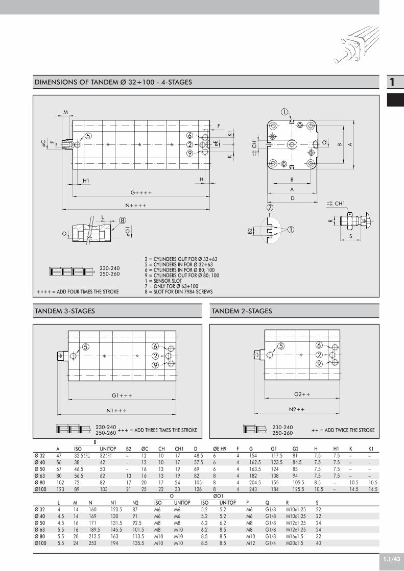
1.1/43
1
8
5
1
7
1
29
6
K
CH1
230-240250-260
øE
H1
M
F
øC
G++++
K1
BQ A
B
CH
A
H
B2
N++++
L
O øO1
R
S
F
D
5
9
62
230-240250-260
N1+++
G1+++
9265
230-240250-260
G2++
N2++
DIMENSIONS OF TANDEM Ø 32÷100 - 4-STAGES
++++ = ADD FOUR TIMES THE STROKE
2 = CYLINDERS OUT FOR Ø 32÷635 = CYLINDERS IN FOR Ø 32÷636 = CYLINDERS IN FOR Ø 80; 1009 = CYLINDERS OUT FOR Ø 80; 1001 = SENSOR SLOT7 = ONLY FOR Ø 63÷1008 = SLOT FOR DIN 7984 SCREWS
TANDEM 3-STAGES TANDEM 2-STAGES
Ø 32Ø 40Ø 50Ø 63Ø 80Ø100
A47566780102123
L44.54.55.55.55.5
Ø 32Ø 40Ø 50Ø 63Ø 80Ø100
ISO32.53846.556.57289
+0.1 –0.4
UNITOP3242506282103
+0.4 –0.1
B2–––131721
ØC121216162025
CH101013131722
CH1171719192430
D48.557.56982105126
ØE H9666888
F444444
G154162.5163.5182204.5243
G1117.5123.5124138155184
G28184.58594105.5125.5
H7.57.57.57.58.510.5
H17.57.57.57.5––
K––––10.514.5
B
M141416162024
N160169171189.5212.5253
ISOM6M6M8M8M10M10
UNITOPM6M6M8M10M10M10
ISO5.25.26.26.28.58.5
UNITOP5.25.26.28.58.58.5
O ØO1
K1––––10.514.5
N1123.5130131.5145.5163194
N2879192.5101.5113.5135.5
PM6M6M8M8M10M12
QG1/8G1/8G1/8G1/8G1/8G1/4
RM10x1.25M10x1.25M12x1.25M12x1.25M16x1.5M20x1.5
S222224243240
++ = ADD TWICE THE STROKE+++ = ADD THREE TIMES THE STROKE

1.1/44
235
230-240
H2+X1
N1+X2+X1
G1+X2+X1
23
1
45
CH
CH1
230-240
A
Q
F
DAB
B
G+X3+X2+X1
H3+X2+X1
H2+X1
H
øC P
H1
øE
L
O
M
N+X3+X2+X1
S
R
DIMENSIONS OF MULTI-POSITION Ø 12÷25 - 3-STAGES
MULTI-POSITION 2-STAGES
2 = CYLINDER 1 OUT3 = CYLINDER 2 OUT5 = CULINDERS 1-2 IN
X1 = CYLINDER 1 STROKEX2 = CYLINDER 2 STROKE
Ø 12Ø 16Ø 20*Ø 25**Standard UNITOP
A292936.540.5
B18182226
ØC681010
CH5788
CH110131717
D303037.541.5
ØE H96666
F4444
G89898992
G163.563.563.566
H8888
H18888
H233.533.533.534
H359595960
L10101010
M8101212
N93.593.593.597.5
N168686871.5
OM4M4M5M5
PM3M4M5M5
QM5M5M5M5
RM6M8M10x1.25M10x1.25
S16202222
1 = SENSOR SLOT2 = CYLINDER 1 OUT3 = CYLINDER 2 OUT4 = CYLINDER 3 OUT5 = CULINDERS 1-2-3 IN
X1 = CYLINDER 1 STROKEX2 = CYLINDER 2 STROKEX3 = CYLINDER 3 STROKE

1.1/45
1
25
9
1
34
7
1
6
8K
CH1
230-240250-260
Q
A
CH B
D
B
S
R
øC
M
P
G+X3+X2+X1
K1
F
E A
L
O øO1
B2
H1 H
N+X3+X2+X1
H2+X1
H3+X2+X1
DIMENSIONS OF MULTI-POSITION Ø 32÷100 - 3-STAGES
5 329
6
230-240250-260
H2+X1
G1+X2+X1
N1+X2+X1
Ø 32Ø 40Ø 50Ø 63Ø 80Ø100
A47566780102123
K––––10.514.5
Ø 32Ø 40Ø 50Ø 63Ø 80Ø100
ISO32.53846.556.57289
+0.1 –0.4
UNITOP3242506282103
+0.4 –0.1
B2–––131721
ØC121216162025
CH101013131722
CH1171719192430
D48.557.56982105126
ØE H9666888
F444444
G117.5123.5124138155184
G18184.58594105.5125.5
H7.57.57.57.58.510.5
H17.57.57.57.5––
H24446.54751.55869.3
B
K1––––10.514.5
L44.54.55.55.55.5
ISOM6M6M8M8M10M10
UNITOPM6M6M8M10M10M10
ISO5.25.26.26.28.58.5
UNITOP5.25.26.28.58.58.5
O ØO1
H380.585.58695.5107.5128
M141416162024
N1879192.5101.5113.5135.5
PM6M6M8M8M10M12
QG1/8G1/8G1/8G1/8G1/8G1/4
RM10x1.25M10x1.25M12x1.25M12x1.25M16x1.5M20x1.5
S222224243240
MULTI-POSITION 2-STAGES
N123.5130131.5145.5163194
2 = CYLINDER 1 OUT FOR Ø 32÷633 = CYLINDER 2 OUT FOR Ø 32÷1005 = CYLINDER 1-2 IN FOR Ø 32÷636 = CYLINDER 1-2 IN FOR Ø 80÷1009 = CYLINDER 1 OUT FOR Ø 80÷100
X1 = CYLINDER 1 STROKEX2 = CYLINDER 2 STROKE
1 = SENSOR SLOT2 = CYLINDER 1 OUT FOR Ø 32÷633 = CYLINDER 2 OUT FOR Ø 32÷1004 = CYLINDER 3 OUT FOR Ø 32÷1005 = CYLINDER 1-2-3 IN FOR Ø 32÷636 = CYLINDER 1-2-3 IN FOR Ø 80÷1007 = ONLY FOR Ø 63÷1008 = SLOT FOR DIN 7984 SCREWS9 = CYLINDER 1 OUT FOR Ø 80÷100
X1 = CYLINDER 1 STROKEX2 = CYLINDER 2 STROKEX3 = CYLINDER 3 STROKE
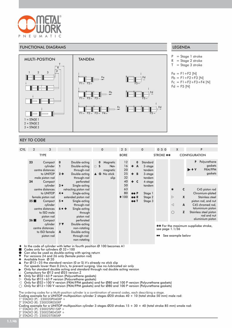
1.1/46
FUNCTIONAL DIAGRAMS LEGENDA
1 2 3
TR
P
F5
Fd
Fd
Fd
F5
F5
F2
F2F1 F3
F2F1 F3
Fc
F1
F4
Fa
Fb
MULTI-POSITION TANDEM
1 = STAGE 12 = STAGE 23 = STAGE 3
P = Stage 1 strokeR = Stage 2 strokeT = Stage 3 stroke
Fa = F1+F2 [N]Fb = F1+F2+F3 [N]Fc = F1+F2+F3+F4 [N]Fd = F5 [N]
! In the code of cylinder with letter in fourth position Ø 100 becomes A1" Codes only for cylinders Ø 32÷100# Can also be used as double-acting with spring return$ For versions 24 and 26 only (female piston rod)! Available from Ø 20% For Ø12÷25 the standard version (0 or S) it’s already no stick slip For speeds lower than 0.2m/s, to prevent surging. Use no-lubricated air only& Only for standard double acting and standard through rod double acting version' Compulsory for Ø12 and Ø25 version Z" Only for Ø32÷63 P version (Polyurethane gaskets)! Only for Ø12÷63 P version (Polyurethane gaskets)" Only for Ø32÷100 V version (FKM/FPM gaskets) and for Ø80 and 100 P version (Polyurethane gaskets)( Only for Ø12÷100 V version (FKM/FPM gaskets) and for Ø80 and 100 P version (Polyurethane gaskets)
The ordering codes for a Multi-position cylinder is a combination of several codes, each describing a stage.Coding example for a UNITOP multiposition cylinder 2 stages Ø20 strokes 40 + 10 (total stroke 50 mm) male rod:1° STADIO (P) : 230020P040XP +2° STADIO (R): 230020R050XPCoding example for a UNITOP multiposition cylinder 3 stages Ø20 strokes 15 + 30 + 40 (total stroke 85 mm) smale rod:1° STADIO (P): 230025P015XP +2° STADIO (R): 230025R045XP +3° STADIO (T): 230025T085XP
KEY TO CODE
CYL 2 3
23 Compactcylinder
centre distancesto UNITOP
male piston rod24 Compact
cylindercentre distances
to UNITOPfemale piston rod
25 " Compactcylinder
centre distancesto ISO male
piston rod26 " Compact
cylindercentre distances
to ISO femalepiston rod
1
0 Double-acting1 Double-acting
through-rod2 ! Double-acting
through-rodperforated
3 ) Single-actingretracting piston rod
4 ) Single-actingextended piston rod
5 ) Single-actingthrough-rod
6 ) ! Single-actingthrough
piston rodperforated
7 $ Double-actingnon-rotating
A Double-actingthrough-rodnon-rotating
2 5
121620253240506380
!100
0 5 0
TYPE STROKE ""
0
0 Standard! A 2-stage
tandem! B 3-stage
tandem! C 4-stage
tandem
## P Stage 1## R Stage 2## T Stage 3
0
0 Magnetic' S Non-
magnetic% G No stick
slip
CONFIGURATIONBORE
" C C45 piston rodChromium-plated
! X Stainless steelpiston rod, and nut
" A C45 chromed rod,taluminium piston
( Z Stainless steel pistonrod and nut
aluminium piston
P
P Polyurethanegaskets
& ! V FKM/FPMgaskets
X
"" For the maximum suppliabe stroke,see page 1.1/36
)) See example below

1.1/47
1
ACCESSORIES
C
A
H
N+
N1+
B
øE
DS
R
UNITOP
ISO
H14
H14
H9
B1
B
B1
B
M1
M
S
D
N+
R
H9
h14 D
N+
S
M
B
FOOT - MODEL A
Ø121620253240506380100
UNITOP CodesW0950126001W0950126001W0950206001W0950256001W0950322001W0950406001W0950506001W0950636001W0950806001W0951006001
A3030364045606884102123
B17.517.52222352832394245
C181822263242506282103
D13131616242024273033
ØE5.55.56.66.6799111113.5
H2222273031.942.54759.565.578
N55.555.558.558.574.5727784.594109.5
N16464707092.585.593.5104116132.5
S3344456688
Ø3240506380100
ISO CodesW0950322001W0950402001W0950502001W0950632001W0950802001W0951002001
A4552657595115
B354347476165
C323645506375
D242832324141
ØE79991214
H31.93645506371
N74.5808589.5105117.5
N192.5101.5109.5114138148.5
S444666
FEMALE HINGE-MODEL B
Ø3240506380100
UNITOP CodesW0950322003W0950406003W0950506003W0950636003W0950806003W0951006003
B4552607090110
B1262832405060
D222527323641
M101212161620
N72.5778089.5100117.5
R1112.512.5151520
S10911111315
Ø3240506380100
ISO CodesW0950322003W0950402003W0950502003W0950632003W0950802003W0951002003
B4552607090110
B1262832405060
D222527323641
M101212161620
N72.5778089.5100117.5
R111313171721
S101012121616
MALE HINGE-MODEL BA
Ø12162025
UNITOP CodesW0950126004W0950126004W0950206004W0950256004
B12121616
D16162020
M6688
N58.558.562.562.5
R6688
S6666
Ø3240506380100
ISO CodesW0950322004W0950402004W0950502004W0950632004W0950802004W0951002004
B262832405060
D222527323641
M101212161620
N72.5778089.5100117.5
R111313171721
S101012121616
Weight [g]262646527688176276392558
Weight [g]76100162266456572
Weight [g]1161842664706701110
Weight [g]74116176468536925
Weight [g]24244448
Weight [g]94124220316578850
Note: Supplied with 4 screws, 4 washers, 2 snap-rings and 1 pin.
Note: Supplied with 4 screws, 4 washers
!!
! Non UNITOP norm fixing distanceNote: Individually packed with 2 screws.
!!
! Non UNITOP norm fixing distance
+ = ADD THE STROKE
+ = ADD THE STROKE
+ = ADD THE STROKE
M1141418-2328

1.1/48
E
AN+ N+
S S
C B
N+
S S
N+A
D
C B
E
R
M
B
S
N+
D
FLANGE Ø 12÷25 - MODEL C (FRONT AND REAR)
Ø12162025
CodesW0950126002W0950126002W0950206002W0950256002
A29293640
B55557076
C43435560
E5.55.56.66.6
N48484849.5
S10101010
Weight [g]112112184226
Note: Supplied with 4 screws.
FLANGE Ø 32÷100 - MODEL C (FRONT AND REAR)
Ø3240506380100
UNITOP CodesW0950322002W0950406002W0950506002W0950636002W0950806002W0951006002
A50606887107128
B80102110130160190
C648290110135163
D323645506375
E79991214
N54.555.557.5657181.5
S101012151515
Ø3240506380100
ISO CodesW0950322002W0950402002W0950502002W0950632002W0950802002W0951002002
A5055657595115
B8090110120153178
C647290100126150
D323645506375
E79991214
N54.555.557.5627282.5
S101012121616
ARTICULATED MALE HINGE - MODEL BAS
Ø3240506380100
ISO CodesW0950322006W0950402006W0950502006W0950632006W0950802006W0951002006
B141616212125
D222527323641
M101212161620
N72.5778089.5100117.5
R161919242430
S101012121616
Weight [g]246454655125519002700
Weight [g]24629052267014202040
Weight [g]106142236336572840
Note: Supplied with 4 screws.
Note: Supplied with 4 screws, 4 washers.
!!
! Non UNITOP norm fixing distance
+ = ADD THE STROKE
+ = ADD THE STROKE
+ = ADD THE STROKE
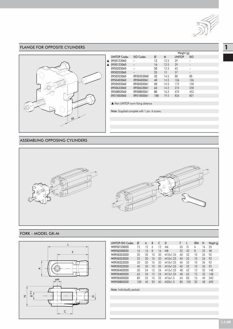
1.1/49
1
M
B12
øM
F
L
B
A
C
DN
FLANGE FOR OPPOSITE CYLINDERS
Ø121620253240506380100
UNITOP Codes0950123060095012306009502030600950253060095032306009504030600950503060095063306009508030600951003060
M12.512.512.51314.514.514.514.516.519.5
ISO Codes––––095032306009504030610950503061095063306109508030610951003061
ASSEMBLING OPPOSING CYLINDERS
FORK - MODEL GK-M
Ø121620253240506380100
UNITOP-ISO CodesW0950120020W0950200020W0950322020W0950322020W0950322020W0950322020W0950402020W0950402020W0950502020W0950802020
A12162020202024243240
B681010101012121620
C12162020202024243240
DM6M8M10x1.25M10x1.25M10x1.25M10x1.25M12x1.25M12x1.25M16x1.5M20x1.5
F24324040404048486480
L314252525252626283105
ØM681010101012121620
N16222626262632324048
Weight [g]204892929292148148340690
UNITOP2929455788106172274470826
ISO––––88106158258452801
Weight [g]
Note: Supplied complete with 1 pin, 4 screws.
!!
! Non UNITOP norm fixing distance
Note: Individually packed.

1.1/50
H7
CH
-0.1
2+
0
B1
F
L
D
C
A
øM
B
øG øG1
ROD EYE - MODEL GA-M
Ø121620253240506380100
UNITOP-ISO codesW0950120025W0950200025W0950322025W0950322025W0950322025W0950322025W0950402025W0950402025W0950502025W0950802025
ØG1
1°30
'1°
30'
CH
P
B
B
øD1
F
øD
øG
S1 S
A
AC
COMPENSATION JOINT - MODEL GA
A20242828282832324250
B9121414141416162125
B16.75910.510.510.510.512121518
C11131515151517172327
CH11141717171719192230
DM6M8M10x1.25M10x1.25M10x1.25M10x1.25M12x1.25M12x1.25M16x1.5M20x1.5
F30364343434350506477
ØG1012.51515151517.517.52227.5
ØG113161919191922222734
L404857575757666685102
ØM681010101012121620
UNITOP-ISO CodesW0950326021W0950326021W0950326021W0950326021W0950406021W0950406021W0950506021W0950806021
Weight [g]285078787878116116226404
I
LF
C
A
E
G
N
B
M
H
D
COUNTER-HINGE CETOP Ø 32÷100
Ø3240506380100
UNITOP-ISO CodesW0950322008W0950402008W0950502008W0950632008W0950802008W0951002008
A262832405060
B192626333344
C799111114
D101212161620
E253232404050
F203232505070
G324545636390
H3754547575103
I415252636380
L182525323240
M81010121216
N101212151522
Weight [g]96216212440464985
Note: Supplied complete with 4 screws, 4 washers.
Note: Individually packed.
Note: Individually packed.
Ø20253240506380100
A4949494959597989
B3636363642425865
C3030303036364451
ØD1111111114141719
ØD16.56.56.56.58.58.510.512.5
FM10x1.25M10x1.25M10x1.25M10x1.25M12x.125M12x1.25M16x1.5M20x1.5
ØG39.539.539.539.544445969
ØG11717171719192631
P6.56.56.56.58.58.510.512.5
S1212121215152020
S11010101013.513.51520
Weight [g]1721721721722862866281200
CH1313131315152227

1.1/51
1R
S
F
A
C
øD
øMB
E
COUNTER-HINGE Ø 16÷25 - MODEL BC
Ø12162025
UNITOP CodesW0950120005W0950120005W0950200005W0950200005
A25253232
B25253030
C15152020
ØD5.55.56.56.5
E2244
F27273030
ØM6688
R771010
S3344
5°
5°
SW4SW5
SW3
SW1
SW2B
D
A A øF
C
øE
SELF ALIGNING ROD COUPLER - MODEL GA-K
Ø121620253240506380100
UNITOP-ISO CodesW0950120030W0950200030W0950322030W0950322030W0950322030W0950322030W0950402030W0950402030W0950502030W0950802030
AM6M8M10x1.25M10x1.25M10x1.25M10x1.25M12x1.25M12x1.25M16x1.5M20x1.5
B10202020202024243240
C10202020202020203240
D3557717171717575103119
ØF8.512.52222222222223232
SW1571212121212122020
SW213173030303030304141
SW313173030303030304141
SW47111919191919193030
SW510131717171719192430
Weight [g]40407878
Weight [g]2456216216216216220220620680
4
1
6.6
M35 M4
3
10
2.5
SLOTTED FIXINGPLATE
DescriptionFIXING BLOCK
Code0950003000
Note: Supplied complete with 1 M3 grub screw and 1 M4 grub screw.
Note: Supplied complete with 1 pin and and 2 snap rings
Note: Individually packed.
ØE2444444444
Weight [g]2

1.1/52
5.8 500
4.9
BAR FOR GROOVING
DescriptionBAR FOR GROOVING L=500 mm
CodeW0950000160
RETRACTABLE SENSOR WITH INSERTION FROM ABOVE
DescriptionHALL N.O. SENSOR, VERTICAL INSERTION 2.5mHALL N.O. SENSOR, VERTICAL INSERTION 300 mm M8REED N.O. SENSOR, VERTICAL INSERTION 2.5mREED N.O. SENSOR, VERTICAL INSERTION 300 mm M8HALL N.O. SENSOR, VERTICAL INSERTION 2m ATEX
CodeW0952025390W0952029394W0952022180W0952028184W0952125556
Note: The code corresponds to 1 piece.
This type of sensor can be inserted in the slot of the sensor from above. This means thecylinder heads do not require a through opening.
black
HALL EFFECT+
+
brown
blue
PNP
blue
black
-
blue
brown
brown
34
1
REED EFFECT+
+-
brown
3blue 4
1
M8
M8
WIRING DIAGRAM TECHNICAL DATA
Type of contactSwitchSupply voltage (Ub) VPower WVoltage variationVoltage drop VInput current mAOutput current mASwitching frequency HzShort-circuit protectionOver-voltage suppressionPolarity inversion protectionEMCLED displayMagnetic sensitivityRepeatabilityDegree of protection (EN 60529)Vibration and shock resistanceTemperature range °CSensor capsule material2.5m/2m connecting cableConnecting cable with M8x1Wire NO.
Reed Effetto Hall Effetto HallN.O. N.O. N.O.
- PNP PNP10 ÷ 30 AC/DC 10 ÷ 30 DC 18 ÷ 30 DC3 (peak valve=6) 3 ! 1.7
- ! 10% di Ub ! 10% di Ub- ! 2 ! 2.2- ! 10 ! 10
! 100 ! 100 ! 70! 400 ! 5000 1000
- Yes Yes- Yes Yes- Yes Yes
EN 60 947-5-2 EN 60 947-5-2 EN 60 947-5-2Yellow Yellow Yellow
2,8 mT ±25% 2,8 mT ±25% 2.6! 0,1 mT ! 0,1 mT ! 0,1 (Ub and ta fixed)
IP 67 IP 67 IP 68, IP 69K30 g, 11 ms, 10÷55 Hz, 1mm 30 g, 11 ms, 10÷55 Hz, 1mm 30 g, 11 ms, 10÷55 Hz, 1mm -25 ÷+75 -25 ÷ +75 -20 ÷ +45
PA66 + PA6I/6T PA66 + PA6I/6T PAPVC; 2 x 0,12 mm2 PVC; 3 x 0,14 mm2 PVC; 3 x 0,12 mm2
Polyurethane; 2 x 0,14 mm2 Polyurethane; 3 x 0,14 mm2 -2 3 3
ATEX

1.1/53
1
12
10
11
6 5 87 2 4
913
COMPACT CYLINDERS, SERIES CMPC
SPARE PARTS
TypeComplete set of gaskets polyurethaneFront cylinder head kit for UNITOP polyurethaneFront cylinder head kit for ISO Ø 32 polyurethaneFront cylinder head kit for ISO polyurethaneRear cylinder head kit for UNITOP polyurethaneRear cylinder head kit for ISO Ø 32 polyurethaneRear cylinder head kit for ISO polyurethanePiston kit polyurethaneMagnetFront + rear cylinder head + piston kit for UNITOP polyurethane
Front + rear cylinder head + piston kit for ISO Ø 32 polyurethane
Front + rear cylinder head + piston kit for ISO polyurethane
Parts! " #
$ % " # &$ % " # &$ % " # &
# & '# & '# & '
! ( ) * +(
$ ! ( " % #& ' ) * +
$ ! ( " % #& ' ) * +
$ ! ( " % #& ' ) * +
BoresØ 12÷100Ø 12÷100
Ø 32Ø 40÷100Ø 12÷100
Ø 32Ø 40÷100Ø 12÷100Ø 12÷100Ø 12÷100
Ø 32
Ø 40÷100
Codes009 . . . 7001009 . . . 71010090327101009 . . . 8101009 . . . 72010090327201009 . . . 8201009 . . . 7401009 . . . 7501009 . . . 7901
0090327901
009 . . . 8901

1.1/54
COMPACT STOPPER CYLINDERØ 20, Ø 32, Ø50, Ø 80
Compact stopper cylinders designed for stopping movingparts or chucks.• With or without magnet execution• Single-acting, oversize extended piston rod• Can be also used as double-acting whith spring return• Fixing centre distances to ISO 15552 for Ø 32, Ø50,
Ø80 and French standard NFE 49-004-1 and 2 (UNITOP).In the relevant cylinder slots, it is possible to mount retracting magnetic sensor.
max 10 bar (max 1 MPa-145 psi) –10°C÷+80°C
Unlubricated air. Lubrication, if used, must be continuous. Ø 20 x15; Ø 32 x 20; Ø50 x 30; Ø 80 x 30; Ø 80 x 40 awith NFE 49-004-1 and 2 fixing centre distances (UNITOP)
Ø 32 x 20; Ø 50 x 30; Ø 80 x 30; Ø 80 x 40 with ISO 15552 fixing centre distances.With profile, heads with screws
Single-acting extended rod, Can be also used as double-acting whith spring returnAll versions come complete with magnet. Supplied without magnet on request.
For correct operation, it is advisable to use 50 m filtered airØ 20: 1,2 bar; Ø 32 e Ø 50: 1 bar; Ø 80: 0,5 bar
See GENERAL TECHNICAL DATA PAGE 1.1/07
TECHNICAL DATAOperating pressureTemperature rangeFluidStroke bore mm
mmDesignVersionsMagnet for sensorsNotesInrush pressureWeight
COMPONENTS Ø 20
! PISTON ROD: Stainless steel, thick chromed" HEAD: extruded anodised aluminium alloy# BARREL: drawn anodised and calibrated aluminium alloy$ PISTON GASKET: polyurethane% MAGNET: neodymium-plastic& PISTON ROD GASKET: polyurethane' GUIDE BUSHING: steel strip with bronze and PTFE insert( STATIC O-RINGS: NBR) SECURING SCREWS: zinc-plated steel* RETURN SPRING: spring stainless steel+ WHEEL: zinc-plated steel
453 10 821 67
11
9
Chuck impact direction

1.1/55
1COMPONENTS Ø 32, Ø 50, Ø 80
! PISTON ROD: Stainless steel, thick chromed" HEAD: extruded anodised aluminium alloy# JACKET: drawn anodised and calibrated aluminium alloy$ PISTON GASKET: polyurethane% MAGNET: Ø32 neodymium-plastic - Ø 50÷80 plastoferrite& PISTON ROD GASKET: polyurethane' GUIDE BUSHING: steel strip with bronze and PTFE insert.( STATIC O-rings: NBR) SECURING SCREWS: zinc-plated steel* RETURN SPRING: spring stainless steel+ WHEEL: zinc-plated steel
7 6
11
3
9
54 10 821
C DA B
• Fixing with screws, using the thread in the rear heads (Fig. A).• Direct fixing from above using long through screws or tie rods (Fig. B). Non-magnetic stainless steel must be used
(e.g. AISI 304)• Fixing with screws, using the thread in the front heads (Fig. C).• Fixing using flange fixed onto the cylinder (Fig. D)
FORCE OF SPRINGS IN COMPACT STOPPER CYLINDERS (THEORETICAL)
Stroke boreMin. load (N)Max. load (N)
Ø 20 x 1513,721,2
Ø 32 x 2022,436,0
Ø 50 x 3050,2115,9
Ø 80 x 3097,9178,5
Ø 80 x 4071,0178,5
COMPACT STOPPER CYLINDER FIXING OPTIONS

1.1/56
VALVE ASSEMBLY ON CYLINDER
TRUNNION VERSION
A
D
C
BE
With this type of cylinder, thevalves (D) can be mounteddirectly using the retractingsensor slot, without requiringthe use of intermediate brackets.This can be done using thespecial plates (A) which comewith both M3 and M4 threads,and screws (B) of the size, typeand quantity shown in the tablebelow.The plates are suppliedcomplete with 2 stud pins, oneM3 and one M4 (C).After the valve centre distanceand the position of the valvehave been determined, theplates can be secured to thecylinder. A “position memory”will be created to facilitatesubsequent maintenance on thevalve.
LOAD GRAPH
With stopper cylinders it is important to keep to the values shown in the graph to prevent early breakage of the mechanical parts.The values shown are only valid with about 1 mm plastic deformation (stopper on chuck).
ROLLER VERSION
ø32
ø20
100
40
150
ø50
15100
0 5 30 3520 25
ø80
50
100
ø20
40
ø32
150
15100
0 5 30 3520 25
ø50
50
Type of valveto mount (D)
MACH 11SERIE 70 1/8SERIE 70 1/4
Fixingplate (A)
cod. 0950003000n. 2n. 2n. 2
Position memory:grub screw (C)
to be usedM4M3M3
Screw (B) forconnection to the cylinder
(one per plate)M3x16 UNI 5931 (DIN 912)M4x25 UNI 5931 (DIN 912)M4x30 UNI 5931 (DIN 912)
Washer (B)(one per screw)
A3.2 UNI 1751 (DIN 127A)—
A4.3 UNI 1751 (DIN 127A)
Impa
ct m
ass
[kg]
Impa
ct m
ass
[kg]
Impact velocity [m/min] Impact velocity [m/min]

1.1/57
1
ORDERING CODESDescriptionCompact stopper cylinder, trunnion Ø32, stroke 20 UNITOPCompact stopper cylinder, trunnion Ø32, stroke 20 ISO 15552Compact stopper cylinder, trunnion Ø32, stroke 20 UNITOP (non-magnetic version)Compact stopper cylinder, trunnion Ø32, stroke 20 ISO 15552 (non-magnetic version)Compact stopper cylinder, trunnion Ø50, stroke 30 UNITOPCompact stopper cylinder, trunnion Ø50, stroke 30 ISO 15552Compact stopper cylinder, trunnion Ø50, stroke 30 UNITOP (non-magnetic version)Compact stopper cylinder, trunnion Ø50, stroke 30 ISO 15552 (non-magnetic version)
Code23B0320020XP25B0320020XP23BS320020XP25BS320020XP23B0500030XP25B0500030XP23BS500030XP25BS500030XP
1
23B
4553
4
M5
22
22
36.5
36.5
8
64.5
ø12
ø26
15
18.5
ø4.2
M5
37.5ø6
H9
1 = SENSOR SLOT
Ø20 STROKE 15 mm TRUNNION VERSION
ORDERING CODES
1
823B25B
øC
Q
N1
A
H1
H
B
N
L
øD1 øE B DAG
øO1
O
F
1 = SENSOR SLOT8 = SEAT FOR DIN 7984 SCREWS
Ø 32 STROKE 20 mm; Ø 50 STROKE 30 mm TRUNNION VERSION
A4767
Ø 32x20Ø 50x30
ØC2032
QG1/8G1/8
D48.569
ØE H966
F44
H7.57.5
L44.5
N80.599.5
N12030
ISO5.26.2
UNITOP5.26.2
ØO1ISOM6M8
UNITOPM6M8
OD13853
ISO32.546.5
UNITOP3250
B
+0.1 –0.4
+0.4 –0.1
G64.575.5
H15768
Code23B0200015XP23BS200015XP
DescriptionCompact stopper cylinder, trunnion ø20, stroke 15Compact stopper cylinder, trunnion ø20, stroke 15 (non-magnetic version)

1.1/58
1
R5
23C
4553
4
22
22
2
37.5
ø12
ø26
36.5
18.5
2
3
ø4.2
M5
4.5
424
36.5
8 M5
64.5
ø6H
9
1 = SENSOR SLOT
Ø20 STROKE 15 mm ROLLER VERSION
ORDERING CODES
Code23C0200015XP23CS200015XP
DescriptionCompact stopper cylinder, roller Ø20, stroke 15Compact stopper cylinder, roller Ø20, stroke 15 (non-magnetic version)
A4767102102
Ø 32x20Ø 50x30Ø 80x30Ø 80x40
ØC20325050
D48.569105105
ØE H96688
F4444
H7.57.58.58.5
L44.55.55.5
ISO5.26.28.58.5
UNITOP5.26.28.58.5
ØO1ISOM6M8M10M10
UNITOPM6M8M10M10
OD138537676
ISO32.546.57272
UNITOP32508282
B
+0.1 –0.4
+0.4 –0.1
H15768117.5127.5
G64.575.5126136
Ø 32x20Ø 50x30Ø 80x30Ø 80x40
H23488
H3661010
H43.571111
H57.5121818
QG1/8G1/8G1/8G1/8
N80.599.5141151
N13850.56373
R912.51818
L18101818
1
81
7
R
23C25C
Q
A
BB DA
L1
øC
H5
H4
H3
H1
H
L
øE
H2
NN1
G
øO1
O B2
F
øD1
1 = SENSOR SLOT7 = ONLY FOR Ø808 = SEAT FOR DIN 7984 SCREWS
Ø 32 STROKE 20 mm; Ø 50 STROKE 30 mm; Ø80 STROKE 30 AND 40 mm ROLLER VERSION
B2--1717
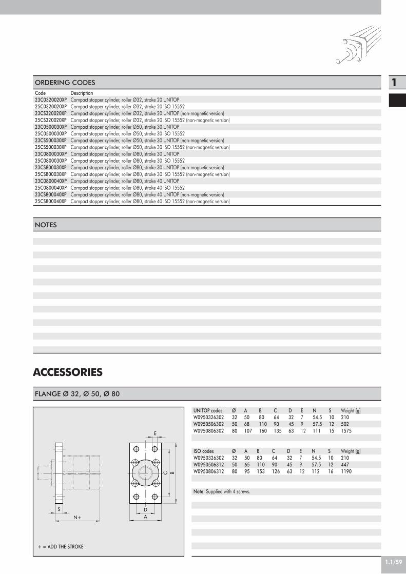
1.1/59
1ORDERING CODESDescriptionCompact stopper cylinder, roller Ø32, stroke 20 UNITOPCompact stopper cylinder, roller Ø32, stroke 20 ISO 15552Compact stopper cylinder, roller Ø32, stroke 20 UNITOP (non-magnetic version)Compact stopper cylinder, roller Ø32, stroke 20 ISO 15552 (non-magnetic version)Compact stopper cylinder, roller Ø50, stroke 30 UNITOPCompact stopper cylinder, roller Ø50, stroke 30 ISO 15552Compact stopper cylinder, roller Ø50, stroke 30 UNITOP (non-magnetic version)Compact stopper cylinder, roller Ø50, stroke 30 ISO 15552 (non-magnetic version)Compact stopper cylinder, roller Ø80, stroke 30 UNITOPCompact stopper cylinder, roller Ø80, stroke 30 ISO 15552Compact stopper cylinder, roller Ø80, stroke 30 UNITOP (non-magnetic version)Compact stopper cylinder, roller Ø80, stroke 30 ISO 15552 (non-magnetic version)Compact stopper cylinder, roller Ø80, stroke 40 UNITOPCompact stopper cylinder, roller Ø80, stroke 40 ISO 15552Compact stopper cylinder, roller Ø80, stroke 40 UNITOP (non-magnetic version)Compact stopper cylinder, roller Ø80, stroke 40 ISO 15552 (non-magnetic version)
Code23C0320020XP25C0320020XP23CS320020XP25CS320020XP23C0500030XP25C0500030XP23CS500030XP25CS500030XP23C0800030XP25C0800030XP23CS800030XP25CS800030XP23C0800040XP25C0800040XP23CS800040XP25CS800040XP
ACCESSORIES
NOTES
AD
C B
E
S
N+
FLANGE Ø 32, Ø 50, Ø 80
Ø325080
UNITOP codesW0950326302W0950506302W0950806302
A5068107
B80110160
C6490135
E7912
N54.557.5111
S101215
Weight [g]2105021575
Note: Supplied with 4 screws.
ISO codesW0950326302W0950506312W0950806312
Ø325080
A506595
B80110153
C6490126
E7912
N54.557.5112
S101216
Weight [g]2104471190
D324563
D324563
+ = ADD THE STROKE

1.1/60
5.8 500
4.9
STRIP
SLIM SENSOR
DescriptionHALL N.O. SENSOR, VERTICAL INSERTION 2.5mHALL N.O. SENSOR, VERTICAL INSERTION 300 mm M8REED N.O. SENSOR, VERTICAL INSERTION 2.5mREED N.O. SENSOR, VERTICAL INSERTION 300 mm M8HALL N.O. SENSOR, VERTICAL INSERTION 2m ATEX
CodeW0952025390W0952029394W0952022180W0952028184W0952125556
DescriptionSLOT STRIP 500 mm
CodeW0950000160
Note: The code corresponds to 1 piece.
This type of sensor can be inserted in the slot of the sensor from above. This means thecylinder heads do not require a through opening.
black
HALL EFFECT+
+
brown
blue
PNP
blue
black
-
blue
brown
brown
34
1
REED EFFECT+
+-
brown
3blue 4
1
M8
M8
WIRING DIAGRAM TECHNICAL DATA
Type of contactSwitchSupply voltage (Ub) VPower WVoltage variationVoltage drop VInput current mAOutput current mASwitching frequency HzShort-circuit protectionOver-voltage suppressionPolarity inversion protectionEMCLED displayMagnetic sensitivityRepeatabilityDegree of protection (EN 60529)Vibration and shock resistanceTemperature range °CSensor capsule material2.5m/2m connecting cableConnecting cable with M8x1Wire NO.
Reed Effetto Hall Effetto HallN.O. N.O. N.O.
- PNP PNP10 ÷ 30 AC/DC 10 ÷ 30 DC 18 ÷ 30 DC3 (peak valve=6) 3 ! 1.7
- ! 10% di Ub ! 10% di Ub- ! 2 ! 2.2- ! 10 ! 10
! 100 ! 100 ! 70! 400 ! 5000 1000
- Yes Yes- Yes Yes- Yes Yes
EN 60 947-5-2 EN 60 947-5-2 EN 60 947-5-2Yellow Yellow Yellow
2,8 mT ±25% 2,8 mT ±25% 2.6! 0,1 mT ! 0,1 mT ! 0,1 (Ub and ta fixed)
IP 67 IP 67 IP 68, IP 69K30 g, 11 ms, 10÷55 Hz, 1mm 30 g, 11 ms, 10÷55 Hz, 1mm 30 g, 11 ms, 10÷55 Hz, 1mm -25 ÷+75 -25 ÷ +75 -20 ÷ +45
PA66 + PA6I/6T PA66 + PA6I/6T PAPVC; 2 x 0,12 mm2 PVC; 3 x 0,14 mm2 PVC; 3 x 0,12 mm2
Polyurethane; 2 x 0,14 mm2 Polyurethane; 3 x 0,14 mm2 -2 3 3
ATEX

1.1/61
1OPERATING DIAGRAMS
1 - Deceleration of the chuck as it comes into contact with the piston rod, with plastic deformation of about 1 mm.2 - The cylinder is pressurized to release the chuck.3 - The pressure in the front chamber is maintained until the chuck has passed the stopper cylinder. The piston rod
extends due to the effect of the spring and any pressure in the opposite chamber. The system is now ready to stopthe next chuck.
1 - Deceleration of the chuck as it comes into contact with the piston rod, with plastic deformation of about 1 mm.2 - The cylinder is pressurized to release the chuck.3 - When the pressure in the front chamber drops, the piston rod extends due to the effect of the spring or any pressure
until the wheel reaches the chuck and moves it on.4 - After the chuck has passed, the cylinder extends the piston rod fully. The system is now ready to stop the next chuck.
TRUNNION VERSION
ROLLER VERSION
! " #
! " # $
Direction ofmovement
Direction ofmovement

1.1/62
COMPACT STOPPER CYLINDERS
12 911
136 54 107 2 8
TypeComplete set of gasketsFront cylinder head kit for UNITOPFront cylinder head kit for ISO Ø 32Front cylinder head kit for ISORear cylinder head kit for UNITOP Ø20 - Ø32Rear cylinder head kit for UNITOPRear cylinder head kit for ISO Ø 32Rear cylinder head kit for ISOPiston kit Ø20Piston kitMagnetFront + rear cylinder head + piston kit for UNITOP
Front + rear cylinder head + piston kit for ISO Ø 32
Front + rear cylinder head + piston kit for ISO
Parts! " #
$ % " # &$ % " # &$ % " # &
# & '# & '# & '# & '! ( )
! ( ) * +(
$ ! ( " % #& ' ) * +
$ ! ( " % #& ' ) * +
$ ! ( " % #& ' ) * +
BoresØ 20, Ø 32, Ø 50, Ø 80Ø 20, Ø 32, Ø 50, Ø 80
Ø 32Ø 50, Ø 80Ø 20, Ø32Ø 50, Ø 80
Ø 32Ø 50, Ø 80
Ø 20Ø 32, Ø 50, Ø 80
Ø 20, Ø 32, Ø 50, Ø 80Ø 20, Ø 32, Ø 50, Ø 80
Ø 32
Ø 50, Ø 80
Codes009 . . . 7060009 . . . 71600090327160009 . . . 8160009 . . . 7201009 . . . 72600090327201009 . . . 82600090207401009 . . . 7460009 . . . 7501009 . . . 7960
0090327960
009. . . 8960
SPARE PARTS

1.1/63
1
CYLINDER SERIES “ISO 15552”(EX ISO 6431) Ø 32÷125 mm
COMPONENTS
710 11 123 4 2 86 91 5
Cylinders made to ISO 15552 VDMA available in variousversions and with a wide range of accessories:• Configuration with or without magnet• Single- or double-acting – single- or through-rod• Wide choice of NBR, POLYURETHANE and FKM/FPM
gaskets (for high temperatures)• Special versions on request• Fixing accessories, guide units and mechanical piston
rod lock.
TECHNICAL DATA Polyurethane NBR FKM/FPM Low Temperature
max 10 bar (max 1 MPa - 145 psi)–20°C to +80°C (non-magnetic cyl.) –10°C to +80°C (non-magnetic cyl.) –10°C to +150° (non-magnetic cyl.) –35°C to + 80°C
–20°C to +70°C (magnetic cyl.) –10°C to +70°C (magnetic cyl.)–10°C to +80°C (non-magnetic cyl.) –10°C to +80°C (non-magnetic cyl.) –10°C to +150° (non-magnetic cyl.) –35°C to + 80°C
–10°C to +70°C (magnetic cyl.) –10°C to +70°C (magnetic cyl.)Unlubricated air. Lubrication, if used, must be continuous
Ø 32 ; Ø 40 ; Ø 50 ; Ø 63 ; Ø 80 ; Ø 100 ; Ø 125Heads with Tap Tite screws
Single-acting: for bores Ø 32-63, strokes 0-250 mmDouble-acting: for bores Ø 32-80, strokes 25-2800 mm
for bores Ø 100-125, strokes 25-2600 mmDouble-acting cushioned, Single-acting retracted piston rod cushioned, Through-rod cushioned, Long cushioning,
High-temperature, Piston rod lock, Oil seal, Through-rod oil seal, Low friction, Non-stick-slip*.All versions come complete with magnet. Supplied without magnet on request.
Ø 32; 40: 0.4 barØ 50;63 strokes < 1500 mm: 0.3 bar; strokes ! 1500 mm: 0.4 bar
Ø 80;100;125 strokes < 1500 mm: 0.2 bar; strokes ! 1500 mm: 0.4 barSee GENERAL TECHNICAL DATA PAGE 1.1/05See GENERAL TECHNICAL DATA PAGE 1.1/06
*Using for speeds lower than 0.2m/s, to prevent surging.For no-stick-slip versions use no-lubricated air only
Operating pressureTemperature range Ø 32 ÷ 63
Ø 80 ÷ 125
FluidBoreDesignStandard stroke
Versions
Sensor magnetInrush pressure
Forces generated at 6 bar thrust/retractionWeights
! PISTON ROD: C45 steel or stainless steel, thick chromed
" HEAD: die cast aluminium# PISTON ROD GASKET: polyurethane, NBR or
FKM/FPM$ GUIDE BUSHING: steel strip with bronze and
PTFE insert% BARREL: drawn anodised calibrated aluminium& HALF-PISTON: self-lubricating technopolymer with
built-in cushioning olives (aluminium with PTFE pad for diameters 80-100-125)
' PISTON GASKET: polyurethane, NBR or FKM/FPM( MAGNET: plastoferrite) BUFFER + Static O-rings: NBR or FKM/FPM* CUSHIONING GASKET: polyurethane, NBR or
FKM/FPM+ CUSHIONING NEEDLE: OT 58 with needle out
movement safety system even when fully open, SCREWS: Tap Tite for assembly

1.1/64
DIMENSIONS OF STANDARD VERSION
CH1
CH3 RT
126
121
124
CH2D
TG
TG
N
BG
WH
VD
E PL
EE
E
PL
C1
VA
AKKB1
L0+
L+
Q
B
P
B
F
Ø3240506380100125
+ = ADD THE STROKE
PL10121416182025
VD6.581314121420
A10101010121210
B30354045455560
B1
28333840434954
WH26303737465165
C1
16202525333845
CH1
10131717222227
CH2
17192424303041
CH3
6688101012
KKM10x1.25M12x1.25M16x1.5M16x1.5M20x1.5M20x1.5M27x2
D12162020252532
TG32.53846.556.57289110
VA4444446
F22243232404054
EEG1/8G1/4G1/4G3/8G3/8G1/2G1/2
RTM6M6M8M8M10M10M12
E465464.575.594111135
L120135143158174189225
L0
94105106121128138160
ZM146165180195220240290
BG14.514.517.517.521.521.525..5
N4.54.55.55.55.55.56.5
P6666101012
Q4466778
DIMENSIONS OF THROUGH-ROD VERSION
122
CH3 RT
CH2CH1
VD
C1
ZM++
EE
B1
TGTGKK D
WH
EE
PLPL
WH+
N
BG
L0+ F
B
P
Q
A
ISOISONON ISONON ISONON ISONON ISONON ISONON ISONON ISONON ISO
Upper limit0255075100125150175200225
Stroke< C !< C !< C !< C !< C !< C !< C !< C !< C !< C !
Lower limit255075100125150175200225250
L0- Ø 329494115136157178199220241262
L0 - Ø 40105105129.5154178.5203227.5252276.5301
L0 - Ø 50106106130.5155179.5204228.5253277.5302
L - Ø 32120120141162183204225246267288
L - Ø 40135135159.5184208.5233257.5282306.5331
L - Ø 50143143167.5192216.5241265.5290314.5339
L - Ø 63158158182.5207231.5256280.5305329.5354
+ = ADD THE STROKE++= ADD TWICE THE STROKE
VERSION 126 (SINGLE-ACTING)L0 - Ø 63121121145.5170194.5219243.5268292.5317

1.1/65
1DIMENSIONS OF 100 mm CUSHIONING VERSION
CH3
CH1 CH4CH4
RT
CH2
131
L1+D BKK
A
VD
E
BG
E TG
PLPL
EETG
N
WH1 VA1
C2
B B1
F
P
Q
L0+
+ = ADD THE STROKE
Ø32405063
PL10121416
VD6.581314
A10101010
B30354045
B1
29343838
WH1
106107113.5113.5
C2
9697101.5101.5
CH1
10131717
CH2
17192424
CH3
6688
CH4
27303535
KKM10x1.25M12x1.25M16x1.5M16x1.5
D12162020
TG32.53846.556.5
VA1
7976.576.576.5
F22243232
EEG1/8G1/4G1/4G3/8
RTM6M6M8M8
E465464.575.5
L1200212219.5234.5
L094105106121
BG14.514.517.517.5
N4.54.55.55.5
P6666
Q4466
DIMENSIONS OF 150 mm CUSHIONING VERSION
Ø32405063
WH1
156157162.5162.5
C2
146147150.5150.5
VA1
129121.5119.5123.5
L1
250262268.5283.5
Ø32405063
WH1
206207213.5213.5
C2
196197201.5201.5
VA1
179176.5176.5176.5
L1
300312319.5334.5
DIMENSIONS OF 200 mm CUSHIONING VERSION

1.1/66
127
VAWH
R
L1++
L++
DIMENSIONS OF TANDEM VERSION
125
WH WH
R
L1 + X1 + X2
L + X1 + X2
DIMENSIONS OF OPPOSED VERSION
Ø3240506380100125
WH26303737465165
R555568689292120
L243265280310348368440
L1
295325354384440470570 Refer to standard cylinders for other values.
++= ADD TWICE THE STROKE
Ø3240506380100125
WH26303737465165
VA4444446
R555568689292120
L243265280310348368440
L1
273299321351398423511 Refer to standard cylinders for other values.
X1 = STROKE CYLINDER 1X2 = STROKE CYLINDER 2
1 2

1.1/67
1
5 4 3
2 1
! Rear chamber piston gasket made of polyurethane (Ø 32-125);
" Front chamber piston gasket made of polyurethane (Ø 32-125);
# Rear chamber cushioning gasket made of polyurethane;
$ Front chamber cushioning gasket made of polyurethane;
% Piston rod gasket made of polyurethane.
The low-friction cylinder is typically used as a dandy or tensioning cylinder since it is a single-acting cylinder without a return spring.The configurations are shown below:
1) The best type is A as it involves less friction.2) Type B should be used when the cylinder is working under normal conditions outside the pneumatic cushioning area. Cushioning
is only for emergency use. It acts as a shock absorber in the case of malfunction.3) Type C differs from type A due to the presence of a piston rod gasket that prevents dirt getting in when operating in dirty
environments.4) Type D differs from type B due to the presence of a piston rod gasket that prevents dirt getting in when operating in dirty
environments.5) Type E should be used when the pressurized chamber is the front one.6) For type F, see point 2.
NB. THE CYLINDER IS ALWAYS SINGLE-ACTING WITHOUT A RETURN SPRING.
LOW-FRICTION VERSION – CODE 123
Rear chamber pressureRear chamber pressure and cushioning in case of impactRear chamber pressure and piston rod gasketRear chamber pressure, cushioning in case of impact and piston rod gasketFront chamber pressureFront chamber pressure and cushioning in case of impact
TypeABCDEF
Gaskets1
1+31+5
1+3+52+5
2+5+4
NOTES

1.1/68
KEY TO CODES
ISO 15552 LOW-FRICTION CYLINDER
ISO 15552 LONG-CUSHIONING CYLINDER
CYL 1 2 3 3 2
3240506380A1=Ø100A2=Ø125
0 0 5 0
Ø32÷Ø80stroke 25÷2800 mmØ100÷Ø125stroke 25÷2600 mm
C
A C45 chromed rod,aluminium piston rod:
standard for all cylinderswith ! 1000 mm-stroke
cylinders and for cylinderwith Ø 80 mm and over
C C45 chromed rod,technopolymer piston:
standard for cylinders ofØ 32 to Ø 63 mm with
< 1000 mm strokesZ Stainless steel pistonrod and nut aluminium piston
X Stainless steel pistonrod and nut
technopolymer piston
TYPE DIAMETER STROKE
P
N NBR gasketsP Polyurethane gasketsV FKM/FPM gaskets
A
A Low friction, type AB Low friction, type BC Low friction, type CD Low friction, type DE Low friction, type EF Low friction, type F
CYL 1 3 1 3 2
32405063
0 0 5 0
25÷2600 mm
C
A C45 chromed rod,aluminium piston rod
for all sizesZ Stainless steel pistonrod and nut aluminium piston
TYPE DIAMETER STROKE
P
N NBRgaskets
P polyurethanegaskets
V FKM/FPMgaskets
A
A 200 mm front/rear cushioning cone – 200mm ext.B 150 mm front/rear cushioning cone – 150mm ext.C 100 mm front/rear cushioning cone – 100mm ext.D 150 mm front/rear cushioning cone – 200mm ext.E 100 mm front/rear cushioning cone – 200mm ext.F 50 mm front/rear cushioning cone – 100mm ext.G 100 mm front/rear cushioning cone – 150mm ext.
H 200 mm front cushioning cone – 200 mm ext.I 150 mm front cushioning cone – 150 mm ext.L 100 mm front cushioning cone – 100 mm ext.M 150 mm front cushioning cone – 200 mm ext.N 100 mm front cushioning cone – 150 mm ext.O 50 mm front cushioning cone – 100 mm ext.
Q 200 mm rear cushioning cone – 200 mm ext.R 150 mm rear cushioning cone – 150 mm ext.S 100 mm rear cushioning cone – 100 mm ext.T 150 mm rear cushioning cone – 200 mm ext.U 100 mm rear cushioning cone – 200 mm ext.V 50 mm rear cushioning cone – 100 mm ext.
! In the code of cylinder with letter in fourth position Ø 100 becomes A1; Ø 125 becomes A2" Only available for versions with aluminium piston (A or Z)! Available until Ø63 and only the versions with piston in aluminum (A or Z)# For speeds lower than 0.2m/s, to prevent surging. Use no-lubricated air only$ Available up to Ø 100
ISO 15552 STD CYLINDER
CYL 1 2 1
120 Double-acting,cuschioned,
non-magnetic121 Double-acting,
cushioned122 Through-rod124 Double-acting,
non-cuschioned125 Opposed
! 126 Single-acting127 Tandem134 Rod lock version136 Version with
piston rod lock$137 Piston rod lock +
guide unit
0
0 DiameterS Non-
magnetic# G No stick slip
3 2
32 40 50 63 80
! 100! 125
0 0 5 0
For the maximumsuppliable strokes,look at the technicaldata
C
A C45 chromed rod,aluminium piston rod:
standard for all cylinderswith ! 1000 mm-stroke
cylinders and for cylinderwith Ø 80 mm and over
C C45 chromed rod,technopolymer piston:
standard for cylinders ofØ 32 to Ø 63 mm with
< 1000 mm strokesZ Stainless steel pistonrod and nut aluminium pistonX Stainless steel piston
rod and nuttechnopolymer piston
TYPE BORE STROKE
P
N NBRgaskets
P polyurethanegaskets
V FKM/FPMgaskets
" B lowtemperature

1.1/69
1INTERMEDIATE HINGE - MODEL EN
TLX MIN
XV+1/2
X+ MAX
TK
TD
UWTL
TM
Code
0950322007095040200709505020070950632007095080200709510020070951252007
Ø
3240506380100125
X (min)
63728386.5104113.5135
XV
7382.59097.5110120145
X (max)
839397108.5116126.5155
TM
50637590110132160
TL
12161620202525
TD e 9
12161620202525
TK
22283235404550
UW
657595105130145175
+ = ADD THE STROKE+ 1/2 = ADD HALF THE STROKE
Weight [g]
2825828801230203026003900
Note: Supplied complete with 4 grub screws, 2 pins
COUNTER-HINGE FOR MODEL EN - MODEL EL
A
HB
A1 ±0.2
øL
E
C
C±
0.1
D1 D H7
D2
Code
W0950322009W0950402009W0950402009W0950632009W0950632009W0951002009W0951002009
Ø
3240506380100125
A
46555565657575
A1
32363642425050
B
182121232328.528.5
C
30363640405050
C1
15181820202525
D2
79911111313
D
12161620202525
D1
11151518182020
E
6.58.58.510.510.512.512.5
Note: Supplied with 4 securing screws
H
10.5121213131616
ØL
22282835354040
Weight [g]
162278278414414715715
ACCESSORIES: FIXINGS
Code0950322090095040209009505020900950632090095080209009510020900951252090
ØØ 32Ø 40Ø 50Ø 63Ø 80Ø 100Ø 125
A5459.571.581.599119.5148
B40404040606060
C29.532.2374253.563.576.5
D110110110110110110110
E64.567.2727788.598.5111.5
D124124124124124124124
E70.573.2788394.5104.5117.9
Applicable valvesMACH 16 Series 70 1/8-1/4 ISO 1 - ISO 2MACH 16 Series 70 1/8-1/4 ISO 1 - ISO 2MACH 16 Series 70 1/8-1/4 ISO 1 - ISO 2MACH 16 Series 70 1/8-1/4 ISO 1 - ISO 2Series 70 1/8-1/4-1/2 ISO 1 - ISO 2Series 70 1/8-1/4-1/2 ISO 1 - ISO 2Series 70 1/8-1/4-1/2 ISO 1 - ISO 2
FIXING BRACKET SERIES KCV
B
A
C
D E
VALVE FIXING BRACKET - CYLINDER (Fig. A)
ISO 1 ISO 2
A B
Weight [g]808693101222258298

1.1/70
KIT FOR FIXING VALVES TO BRACKETSCode09500020030950002004095000200609500020010950002002
Valve kitMACH 16Series 70 1/8-1/4Series 70 1/2ISO 1ISO 2
Composition2 HEX. SCREWS M3x25 with WASHER2 HEX. SCREWS M4x50 with WASHER2 HEX. SCREWS M5x50 with WASHERADAPTOR + ISO1 BASE SIDE + SCREWS + WASHERS (Fig. B)ADAPTOR + ISO 2 BASE SIDE + SCREWS + WASHERS (Fig. B)
Weight [g]4820230350
ACCESSORIES: MAGNETIC SENSORS
VALVE ASSEMBLY ON CYLINDER
FOR Ø 32-40-50-63 FOR Ø 80-100-125
9.1
11.5
25.534
17
ORDERING CODESCodeW0950000201W0950000222W0950000232
DescriptionREED SENSOR ACC. DSM2-C525 HSE.HALL PNP SENSOR ACC. DSM3-N225E. HALL NPN SENSOR ACC. DSM3-M225
13.2
2.7
18.5
M5
5.9
19.2
14
29.5
SENSOR SUPPORT BRACKETS
Code DescriptionW0950000711 BRACKET ACC. D.32 DST 80
Code DescriptionW0950000712 BRACKET ACC. D.50 DST 81
Code DescriptionW0950000713 BRACKET ACC. D.80-100-125 DST 82
Ø 32÷40 Ø 50÷63 Ø 80÷100÷125
29.8
14.8 1.8
20.9
14
M5
20.4
1.6
26
20.6
1.7
7.5
25.9
47.8
M5
14

1.1/71
1TECHNICAL DATATypeContactMax AC/DC voltageMax current at 25°CPower with inductive loadPower with resistive loadSwitch-on timeSwitch-off timeSwitch-on pointSwitch-off pointOperating lifeContact resistanceCable lengthCable cross sectionCable materialCircuit
VmAVA
Wattm secm secGaussGauss
–
mmm2
REED + VARISTORE + LED 2 filiREED + VARISTORE + LED N.O.
3÷48 V(DC); 3÷220 (AC)50010501.20.111095
107 impulsi0.12.5
0.35PVC Morbido
HALL VERSION PNP/NPN 3 wiresHALL EFFECT NO PNP/NPN
6-24 V DC250
–6
0.83
158
109 impulses–
2.50.35
Soft PVC
Version NPN
Version PNP
brown
-
black
brown
black
+
+
-
blue
blue
24V DC
blue
brown
24V AC
+
-
blue
brown ~
~
AC
DC
ADAPTOR FOR RETRACTABLE SENSOR
DescriptionAdaptor DSS005 for DST/ST brackets
CodeW0950001001
ASSEMBLY DIAGRAM
45
3
2 1
! ISO 15552 cylinder with traditional barrel" Sensor bracket mod. DST (Ø32÷125)# Adaptor$ Retractable sensor with insertion from above% Retractable sensor

1.1/72
CYLINDERS SERIES “ISO 15552”(EX ISO 6431) ø32÷125 mmTYPE “A” RETRACTABLE SENSOR
The sensor can be inserted from the side thanks to the newshape of the heads. The profiles of the liners have beenredesigned and the new shape means that dedicatedintermediate hinges can be applied. Cylinders available invarious versions and a wide range of accessories:• Configuration with or without magnet• Single- or double-acting – single- or through-rod• Wide choice of NBR, POLYURETHANE and FKM/FPM
gaskets (for high temperatures)• Special versions on request• Fixing accessories, guide units and mechanical piston
rod lock.
JACKET CROSS SECTION
Polyurethane NBR FKM/FPM Low Temperature
max 10 bar (max 1 MPa - 145 psi)–20°C to +80°C (non-magnetic cyl.) –10°C to +80°C (non-magnetic cyl.) –10°C to +150° (non-magnetic cyl.) –35°C÷+80°C
–20°C to +70°C (magnetic cyl.) –10°C to +70°C (magnetic cyl.)–10°C to +80°C (non-magnetic cyl.) –10°C to +80°C (non-magnetic cyl.) –10°C to +150° (non-magnetic cyl.) –35°C÷+80°C
–10°C to +70°C (magnetic cyl.) –10°C to +70°C (magnetic cyl.)Unlubricated air. Lubrication, if used, must be continuous
Ø 32 ; Ø 40 ; Ø 50 ; Ø 63 ; Ø 80 ; Ø 100 ; Ø 125Heads with Tap Tite screws
Single-acting: for bores Ø 32-63, strokes 0-250 mmDouble-acting: for bores Ø 32-80, strokes 25-2800 mm
for bores Ø 100-125, strokes 25-2600 mmDouble-acting cushioned, Single-acting retracted piston rod cushioned, Through-rod cushioned, Long cushioning,
High-temperature, Piston rod lock, Oil seal, Through-rod oil seal, Low friction, Non-stick-slip*.All versions come complete with magnet. Supplied without magnet on request.
Ø 32; 40: 0.4 barØ 50;63 strokes < 1500 mm: 0.3 bar; strokes ! 1500 mm: 0.4 bar
Ø 80;100;125 strokes < 1500 mm: 0.2 bar; strokes ! 1500 mm: 0.4 barSee GENERAL TECHNICAL DATA PAGE 1.1/05See GENERAL TECHNICAL DATA PAGE 1.1/06
*Using for speeds lower than 0.2m/s, to prevent surging.For no-stick-slip versions use no-lubricated air only
TECHNICAL DATAOperating pressureTemperature range Ø 32 ÷ 63
Ø 80 ÷ 125
FluidBoreDesignStandard stroke
Versions
Sensor magnetInrush pressure
Forces generated at 6 bar thrust/retractionWeights
Ø100Ø125
Ø32 Ø40
1
Ø80Ø63
1
1
11
11
Ø50
31.9
74
31.9
74
63.3
23.5
23.5
63.344
89
4489
108
52.6
52.6
108 13
4
57.6
134
57.6
44.5
13.3
44.5
6.6
53 18.4
53
18.4
! SLOTS FOR RETRACTABLE SENSOR

1.1/73
1DIMENSIONS OF STANDARD VERSION
CH1
CH3 RT
126
121
124
CH2D
TG
TG
N
BG
WH
VD
E PL
EE
E
PL
C1
VA
AKKB1
L0+
L+
Q
B
P
B
F
+ = ADD THE STROKE
DIMENSIONS OF THROUGH-ROD VERSION
CH3 RT
CH2CH1
122
VD
C1
ZM++
EE
B1
TGTGKK D
WH
A EE
PLPL
WH+
N
BG
L0+ F
B
P
Q
+ = ADD THE STROKE++= ADD TWICE THE STROKE
Ø.3240506380100125
PL10121416182025
VD6.581314121420
A10101010121210
B30354045455560
B1
28333840434954
WH26303737465165
C1
16202525333845
CH1
10131717222227
CH2
17192424303041
CH3
6688101012
KKM10x1.25M12x1.25M16x1.5M16x1.5M20x1.5M20x1.5M27x2
D12162020252532
TG32.53846.556.57289110
VA4444446
F22243232404054
EEG1/8G1/4G1/4G3/8G3/8G1/2G1/2
RTM6M6M8M8M10M10M12
E465464.575.594111135
L120135143158174189225
L094105106121128138160
ZM146165180195220240290
BG14.514.517.517.521.521.525..5
N4.54.55.55.55.55.56.5
P6666101012
Q4466778
ISOISONON ISONON ISONON ISONON ISONON ISONON ISONON ISONON ISO
Upper limit0255075100125150175200225
Stroke< C !< C !< C !< C !< C !< C !< C !< C !< C !< C !
Lower limit255075100125150175200225250
L0 - Ø 329494115136157178199220241262
L0 - Ø 40105105129.5154178.5203227.5252276.5301
L0 - Ø 50106106130.5155179.5204228.5253277.5302
L - Ø 32120120141162183204225246267288
L - Ø 40135135159.5184208.5233257.5282306.5331
L - Ø 50143143167.5192216.5241265.5290314.5339
L - Ø 63158158182.5207231.5256280.5305329.5354
VERSION 126 (SINGLE-ACTING)L0- Ø 63121121145.5170194.5219243.5268292.5317

1.1/74
DIMENSIONS OF 100 mm CUSHIONING VERSION
130
CH3
CH1 CH4CH4
RT
CH2
L1+D BKK
A
VD
E
BG
E TG
PLPL
EETG
N
WH1 VA1
C2
B B1
F
P
Q
L0+
+ = ADD THE STROKE
Ø32405063
PL10121416
VD6.581314
A10101010
B30354045
B1
29343838
WH1
106107113.5113.5
C2
9697101.5101.5
CH1
10131717
CH2
17192424
CH3
6688
CH4
27303535
KKM10x1.25M12x1.25M16x1.5M16x1.5
D12162020
TG32.53846.556.5
VA1
7976.576.576.5
F22243232
EEG1/8G1/4G1/4G3/8
RTM6M6M8M8
E465464.575.5
L1
200212219.5234.5
L0
94105106121
BG14.514.517.517.5
N4.54.55.55.5
P6666
Q4466
DIMENSIONS OF 150 mm CUSHIONING VERSION
Ø32405063
WH1
156157162.5162.5
C2
146147150.5150.5
VA1
129121.5119.5123.5
L1
250262268.5283.5
Ø32405063
WH1
206207213.5213.5
C2
196197201.5201.5
VA1
179176.5176.5176.5
L1
300312319.5334.5
DIMENSIONS OF 200 mm CUSHIONING VERSION

1.1/75
1
127
VAWH
R
L1++
L++
DIMENSIONS OF TANDEM VERSION
125
WH WH
R
L1 + X1 + X2
L + X1 + X2
DIMENSIONS OF OPPOSED VERSION
++= ADD TWICE THE STROKE
Ø3240506380100125
WH26303737465165
R555568689292120
L243265280310348368440
L1
295325354384440470570 Refer to standard cylinders for other values.
Ø3240506380100125
WH26303737465165
VA4444446
R555568689292120
L243265280310348368440
L1
273299321351398423511 Refer to standard cylinders for other values.
X1 = STROKE CYLINDER 1X2 = STROKE CYLINDER 2
1 2
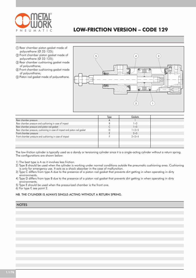
1.1/76
LOW-FRICTION VERSION – CODE 129
The low-friction cylinder is typically used as a dandy or tensioning cylinder since it is a single-acting cylinder without a return spring.The configurations are shown below:
1) The best type is A as it involves less friction.2) Type B should be used when the cylinder is working under normal conditions outside the pneumatic cushioning area. Cushioning
is only for emergency use. It acts as a shock absorber in the case of malfunction.3) Type C differs from type A due to the presence of a piston rod gasket that prevents dirt getting in when operating in dirty
environments.4) Type D differs from type B due to the presence of a piston rod gasket that prevents dirt getting in when operating in dirty
environments.5) Type E should be used when the pressurized chamber is the front one.6) For type F, see point 2.
NB. THE CYLINDER IS ALWAYS SINGLE-ACTING WITHOUT A RETURN SPRING.
Rear chamber pressureRear chamber pressure and cushioning in case of impactRear chamber pressure and piston rod gasketRear chamber pressure, cushioning in case of impact and piston rod gasketFront chamber pressureFront chamber pressure and cushioning in case of impact
TypeABCDEF
Gaskets1
1+31+5
1+3+52+5
2+5+4
NOTES
5 4 3
2 1
! Rear chamber piston gasket made of polyurethane (Ø 32-125);
" Front chamber piston gasket made of polyurethane (Ø 32-125);
# Rear chamber cushioning gasket madeof polyurethane;
$ Front chamber cushioning gasket madeof polyurethane;
% Piston rod gasket made of polyurethane.

1.1/77
1CYLINDER ISO 15552 TYPE “A”, RETRACTABLE SENSOR
CYLINDER ISO 15552 LOW-FRICTION TYPE “A”, RETRACTABLE SENSOR
CYLINDER ISO 15552 LONG-CUSHIONING TYPE “A”, RETRACTABLE SENSOR
CYL 1 2 9 3 2
3240506380A1=Ø100A2=Ø125
0 0 5 0
Ø32÷Ø80stroke 25÷2800 mmØ100÷Ø125stroke 25÷2600 mm
C
A C45 chromed rod,aluminium piston rod:
standard for all cylinderswith ! 1000 mm-stroke
cylinders and for cylinderwith Ø 80 mm and over
C C45 chromed rod,technopolymer piston:
standard for cylinders ofØ 32 to Ø 63 mm with
< 1000 mm strokesZ Stainless steel pistonrod and nut aluminium pistonX Stainless steel piston
rod and nuttechnopolymer piston
TYPE DIAMETER STROKE
P
N NBR gasketsP Polyurethane gasketsV FKM/FPM gaskets
A
A Low friction, type AB Low friction, type BC Low friction, type CD Low friction, type DE Low friction, type EF Low friction, type F
CYL 1 3 0 3 2
32405063
0 0 5 0
25÷2600 mm
C
A C45 chromed rod,aluminium piston rod
for all sizesZ Stainless steel pistonrod and nut aluminium piston
TYPE DIAMETER STROKE
P
N NBRgaskets
P polyurethanegaskets
V FKM/FPMgaskets
A
A 200 mm front/rear cushioning cone – 200mm ext.B 150 mm front/rear cushioning cone – 150mm ext.C 100 mm front/rear cushioning cone – 100mm ext.D 150 mm front/rear cushioning cone – 200mm ext.E 100 mm front/rear cushioning cone – 200mm ext.F 50 mm front/rear cushioning cone – 100mm ext.G 100 mm front/rear cushioning cone – 150mm ext.
H 200 mm front cushioning cone – 200 mm ext.I 150 mm front cushioning cone – 150 mm ext.L 100 mm front cushioning cone – 100 mm ext.M 150 mm front cushioning cone – 200 mm ext.N 100 mm front cushioning cone – 150 mm ext.O 50 mm front cushioning cone – 100 mm ext.
Q 200 mm rear cushioning cone – 200 mm ext.R 150 mm rear cushioning cone – 150 mm ext.S 100 mm rear cushioning cone – 100 mm ext.T 150 mm rear cushioning cone – 200 mm ext.U 100 mm rear cushioning cone – 200 mm ext.V 50 mm rear cushioning cone – 100 mm ext.
CYL 0 0 5 0
For the maximumsuppliable strokes,look at the technicaldata
TYPE STROKE
P
N NBRgaskets
P polyurethanegaskets
V FKM/FPMgaskets
! B lowtemperature
1 2 1
121 Double-acting,cushioned
122 Through-rod124 Double-acting,
non-cuschioned125 Opposed
! 126 Single-acting127 Tandem134 Rod lock version136 Version with piston
rod lock"137 Piston rod lock +
guide unit
A
A Standard# B No stick slip
C Non-magnetic
C
A C45 chromed rod,aluminium piston rod:
standard for all cylinderswith ! 1000 mm-stroke
cylinders and for cylinderwith Ø 80 mm and over
C C45 chromed rod,technopolymer piston:
standard for cylinders ofØ 32 to Ø 63mm with
< 1000 mm strokesZ Stainless steel pistonrod and nut aluminium pistonX Stainless steel piston
rod and nuttechnopolymer piston
3 2
32 40 50 63 80A1=100A2=125
DIAMETER
! Only available for versions with aluminium piston (A or Z)! Available until Ø63 and only the versions with piston in aluminum (A or Z)# For speeds lower than 0.2m/s, to prevent surging. Use no-lubricated air only" Available up to Ø 100
KEY TO CODES

1.1/78
INTERMEDIATE HINGE - MODEL EN
UW
X+ MAX
TMTL
TL
TK TD
X MIN
XV+1/2
Code
0950322107095040210709505021070950632107095080210709510021070951252107
Ø
3240506380100125
X (min)
63728386.5104113.5135
XV
7382.59097.5110120145
X (max)
839397108.5116126.5155
TM
50637590110132160
TL
12161620202525
COUNTER-HINGE FOR MODEL EN - MODEL EL
A
HB
A1 ±0.2
øL
E
C
C±
0.1
D1 D H7
D2
Code
W0950322009W0950402009W0950402009W0950632009W0950632009W0951002009W0951002009
Ø
3240506380100125
A
46555565657575
TD e 9
12161620202525
TK
22282836364550
UW
657595105130145175
A1
32363642425050
B
182121232328.528.5
C
30363640405050
C1
15181820202525
D2
79911111313
D
12161620202525
D1
11151518182020
E
6.58.58.510.510.512.512.5
+ = ADD THE STROKE+ 1/2 = ADD HALF THE STROKE
Note: Supplied with 4 securing screws
H
10.5121213131616
ØL
22282835354040
Weight [g]
170360580950148021402950
Note: Supplied complete with 4 grub screws, 2 pins
Weight [g]
162278278414414715715
ACCESSORIES: FIXINGS
VALVE ASSEMBLY ON CYLINDER
A D B
With this type of cylinder, the valves (D) canbe mounted directly using the retractingsensor slot, without requiring the use ofintermediate brackets.This can be done using the special plates(A), which come with both the M3 and M4threads, and screws (B) of the size, typeand quantity shown in the table below.For ISO 1 and ISO 2 valves, the kit onwhich the valve is to be mounted (codesshown in the tables) will be fitted to thecylinder using the special plates (A) andthe screws (B) listed in the table.
Type of valveto mount (D)
MACH 11SERIE 70 1/8SERIE 70 1/4SERIE 70 1/2ISO 1ISO 2
M3 fixingplate (A)
code 0950003002n° 2
–––––
M4 fixingplate (A)
code 0950003001–
n° 2n° 2n° 2n° 2n° 2
Screw (B)for connection to cylinder
(one per plate)M3x16 UNI 5931 (DIN 912)M4x25 UNI 5931 (DIN 912)M4x30 UNI 5931 (DIN 912)M4x45 UNI 5931 (DIN 912)M4x8 UNI 7688 (DIN 965A)M4x8 UNI 7688 (DIN 965A)
Washer (B)(one per screw)
A3.2 UNI 1751 (DIN 127A)–
A4.3 UNI 1751 (DIN 127A)A4.3 UNI 1751 (DIN 127A)
––
Valveassembly
kit––––
09500020010950002002
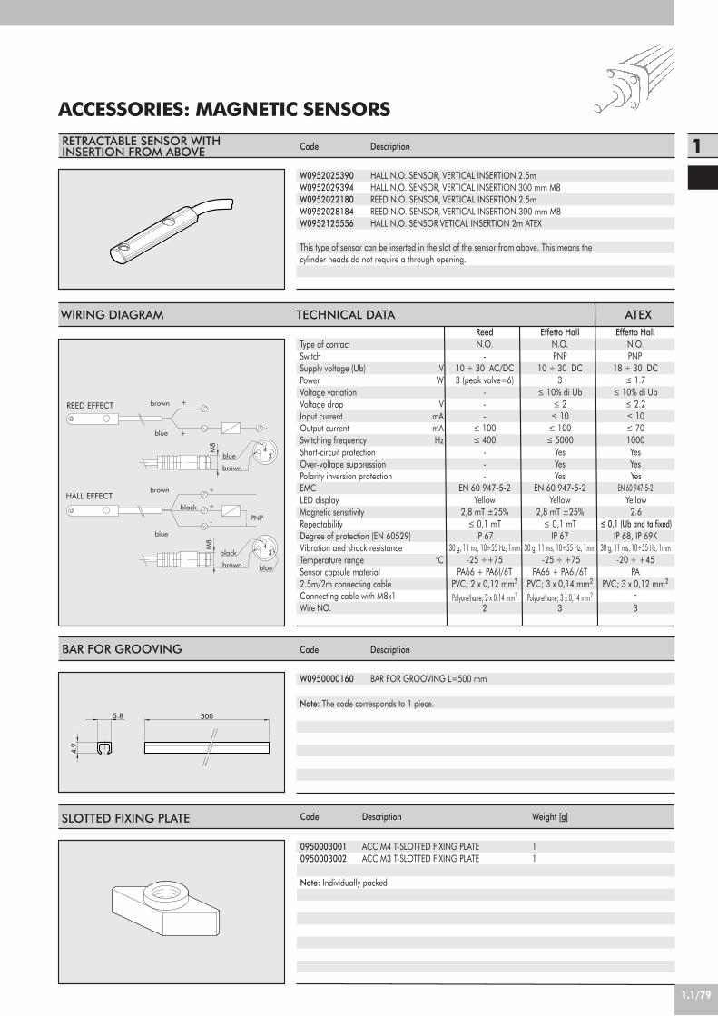
1.1/79
1
ACCESSORIES: MAGNETIC SENSORS
5.8 500
4.9
BAR FOR GROOVING Description
BAR FOR GROOVING L=500 mm
Code
W0950000160
RETRACTABLE SENSOR WITHINSERTION FROM ABOVE Description
HALL N.O. SENSOR, VERTICAL INSERTION 2.5mHALL N.O. SENSOR, VERTICAL INSERTION 300 mm M8REED N.O. SENSOR, VERTICAL INSERTION 2.5mREED N.O. SENSOR, VERTICAL INSERTION 300 mm M8HALL N.O. SENSOR VETICAL INSERTION 2m ATEX
Code
W0952025390W0952029394W0952022180W0952028184W0952125556
Note: The code corresponds to 1 piece.
This type of sensor can be inserted in the slot of the sensor from above. This means thecylinder heads do not require a through opening.
black
HALL EFFECT+
+
brown
blue
PNP
blue
black
-
blue
brown
brown
34
1
REED EFFECT+
+-
brown
3blue 4
1
M8
M8
WIRING DIAGRAM TECHNICAL DATA
Type of contactSwitchSupply voltage (Ub) VPower WVoltage variationVoltage drop VInput current mAOutput current mASwitching frequency HzShort-circuit protectionOver-voltage suppressionPolarity inversion protectionEMCLED displayMagnetic sensitivityRepeatabilityDegree of protection (EN 60529)Vibration and shock resistanceTemperature range °CSensor capsule material2.5m/2m connecting cableConnecting cable with M8x1Wire NO.
Reed Effetto Hall Effetto HallN.O. N.O. N.O.
- PNP PNP10 ÷ 30 AC/DC 10 ÷ 30 DC 18 ÷ 30 DC3 (peak valve=6) 3 ! 1.7
- ! 10% di Ub ! 10% di Ub- ! 2 ! 2.2- ! 10 ! 10
! 100 ! 100 ! 70! 400 ! 5000 1000
- Yes Yes- Yes Yes- Yes Yes
EN 60 947-5-2 EN 60 947-5-2 EN 60 947-5-2Yellow Yellow Yellow
2,8 mT ±25% 2,8 mT ±25% 2.6! 0,1 mT ! 0,1 mT ! 0,1 (Ub and ta fixed)
IP 67 IP 67 IP 68, IP 69K30 g, 11 ms, 10÷55 Hz, 1mm 30 g, 11 ms, 10÷55 Hz, 1mm 30 g, 11 ms, 10÷55 Hz, 1mm -25 ÷+75 -25 ÷ +75 -20 ÷ +45
PA66 + PA6I/6T PA66 + PA6I/6T PAPVC; 2 x 0,12 mm2 PVC; 3 x 0,14 mm2 PVC; 3 x 0,12 mm2
Polyurethane; 2 x 0,14 mm2 Polyurethane; 3 x 0,14 mm2 -2 3 3
SLOTTED FIXING PLATE Description
ACC M4 T-SLOTTED FIXING PLATEACC M3 T-SLOTTED FIXING PLATE
Code
09500030010950003002
Note: Individually packed
Weight [g]
11
ATEX

1.1/80
ACCESSORIES ISO 15552 STD AND TYPE “A”RETRACTABLE SENSOR:MECHANICAL ROD BLOCK
Pilot pressureAmbient temperatureFluid temperatureOperationMechanicsLocking force
Body materialShoe materialSpring materialPiston materialGasket materialPilot port
4-8 bar (0.4-0.8 Mpa)Max 80°C (176°F)Max 70°C (154°F)NC - bidirectionalDouble shoe with mechanical lockØ32 Ø40 Ø50 Ø63 Ø80 Ø100 Ø125650 1100 1600 2500 4000 6300 8700AluminiumBrassNBRSynthetic material with added teflonNBR1/8’’
PpTetg
F(N)
OPERATING PRINCIPLE
The mechanical piston rod lock is a normally-closed mechanism.In the absence of pneumatic piloting, the two shoes (A) lock thecylinder rod in both directions (Fig. 1). With pneumatic piloting,the piston rod guide forces the shoes to come right up to eachother and overcome the counter spring (B) force and the pistonrod can slide (Fig. 2). It is important to remember that themechanical piston rod lock is a static type, which means that itis necessary to stop the cylinder piston rod pneumatically beforelocking the part mechanically.
DIMENSIONS
Q Z
L4T1
L0+
D
L1
L2
D1
L8
M
D2
L7
L7
A
H
D3
f8A
L+
CodeW5010001102W5010001103W5010001104W5010001109W5010001106W5010001107W5010001108
Ø3240506380100125
L1
58658282110115167
L2
4855707090100122
L4
881515181822
L7
4550607090105140
L8
34384849.5616886.5
D12162020252532
D1
30354045455560
D2
3540506080100130
D3
25283538485865
H46.553647595110.5150
A32.53846.556.57289110
T1
13131616202030
MM6M6M8M8M10M10M12
ZM6x20M6x20M8x30M8x30M10x35M10x35M12x40
QM5G1/8G1/8G1/8G1/8G1/8G1/8
L0
94105106121128138160
L162180200215251266347
+ = ADD THE STROKE
A
B
Fig. 1 Fig. 2
Weight [g]150200500700170027005600

1.1/81
1
ACCESSORIES ISO 15552 STD AND TYPE “A”RETRACTABLE SENSOR: FIXINGS
TR
E
ATAH
SA+
A0
AB
XA+
AUM
R
FL
CB
UB
L
øCD
H9
XD+
+= ADD THE STROKE
MR
EW
XD+
øCD
H9
L
FL
+= ADD THE STROKE
+= ADD THE STROKE
MS
EX L øCX
H9
DL
XN+
+= ADD THE STROKE
FOOT - MODEL A Code
W0950322001W0950402001W0950502001W0950632001W0950802001W0951002001W0951252001
Ø
3240506380100125
Ø AB
7999121416
AH
32364550637190
AO
11151515202515
AT
4446667
AU
24283232414145
TR
32364550637590
E
4552657595115140
XA
144163175190215230270
SA
142161170185210220250
Weight [g]
761001622664565721130
Note: ndividually packed with 2 screws.
FEMALE HINGE - MODEL B Code
W0950322003W0950402003W0950502003W0950632003W0950802003W0951002003W0951252003
Ø
3240506380100125
UB
4552607090110130
CB
26283240506070
FL
22252732364150
ØCD
10121216162325
XD
142160170190210230275
MR
10121216162025
L
10101212161620
Note: Supplied with 4 screws, 4 washers, 2 snap-rings, 1 pin.
Weight [g]
11616025239467010852000
MALE HINGE - MODEL BA Code
W0950322004W0950402004W0950502004W0950632004W0950802004W0951002004W0951252004
Ø
3240506380100125
EW
26283240506070
FL
22252732364150
MR
11131317172126
Ø CD
10121216162025
L
12151520202530
XD
142160170190210230275
Weight [g]
941242203165788501590
Note: Supplied with 4 screws, 4 washers
ARTICULATED MALE HINGE - MODEL BAS Code
W0950322006W0950402006W0950502006W0950632006W0950802006W0951002006W0951252006
Ø cil.
3240506380100125
DL
22252732364150
MS
16191924243036
L
12151520202530
XN
142160170190210230275
CX
10121216162025
EX
14161621212531
Weight [g]
1061422363365728401520
Note: Supplied with 4 screws, 4 washers
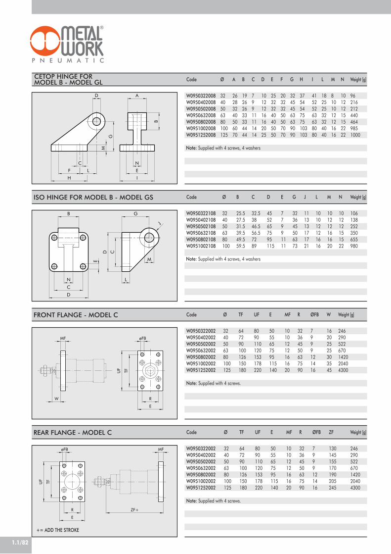
1.1/82
I
LF
C
A
E
G
N
B
M
H
D
J
B G
CD
M
N
C
D
E
L
ZF+
MF
UF TF
E
R
øFB
MF
R
E
TF
øFB
UF
W
+= ADD THE STROKE
CETOP HINGE FORMODEL B - MODEL GL Code
W0950322008W0950402008W0950502008W0950632008W0950802008W0951002008W0951252008
Ø
3240506380100125
A
26283240506070
B
19262633334444
C
79911111414
D
10121216162025
E
25323240405050
F
20323250507070
G
32454563639090
H
3754547575103103
I
41525263638080
L
18252532324040
M
8101012121616
N
10121215152222
Note: Supplied with 4 screws, 4 washers
Weight [g]
962162124404649851000
ISO HINGE FOR MODEL B - MODEL GS Code
W0950322108W0950402108W0950502108W0950632108W0950802108W0951002108
Ø
3240506380100
B
25.527.531.539.549.559.5
C
32.53846.556.57289
D
4552657595115
E
77991111
G
323645506373
J
111313171721
L
101012121616
M
101212161620
N
101212151522
Note: Supplied with 4 screws, 4 washers
Weight [g]
106138252350655980
FRONT FLANGE - MODEL C Code
W0950322002W0950402002W0950502002W0950632002W0950802002W0951002002W0951252002
Ø
3240506380100125
TF
647290100126150180
UF
8090110120153178220
E
5055657595115140
MF
10101212161620
R
32364550637590
ØFB
7999121416
W
16202525303545
Note: Supplied with 4 screws.
Weight [g]
246290522670142020404300
REAR FLANGE - MODEL C Code
W0950322002W0950402002W0950502002W0950632002W0950802002W0951002002W0951252002
Ø
3240506380100125
TF
647290100126150180
UF
8090110120153178220
E
5055657595115140
MF
10101212161620
R
32364550637590
ØFB
7999121416
ZF
130145155170190205245
Weight [g]
246290522670142020404300
Note: Supplied with 4 screws.

1.1/83
1
H
F
CH
B12
øM
F
L
B
A
C
DN
H7
CH
-0.1
2+
0
B1
F
L
D
C
A
øM
B
øG øG1
5°
5°
SW4SW5
SW3
SW1
SW2B
D
A A øF
C
øE
ROD NUT - MODEL S Code
09503220100950402010095050201009508020100951252010
Ø
324050/6380/100125
F
M10x1.25M12x1.25M16x1.5M20x1.5M27x2
H
678912
CH
1719243041
Weight [g]
612203274
Note: Individually packed.
FORK MODEL GK-M Code
W0950322020W0950402020W0950502020W0950502020W0950802020W0950802020W0951252020
Ø
3240506380100125
Ø M
10121616202030
C
20243232404054
B
10121616202030
A
20243232404055
L
52628383105105148
F
404864648080110
D
M10x1.25M12x1.25M16x1.5M16x1.5M20x1.5M20x1.5M27x2
N
26324040404865
Weight [g]
921483403406906901835
Note: Individually packed.
ROD EYE - MODEL GA-M Code
W0950322025W0950402025W0950502025W0950502025W0950802025W0950802025W0951252025
Ø
3240506380100125
Ø M
10121616202030
C
15172222262636
B1
10.5121515181825
B
14162121252537
A
28324242505070
D
M10x1.25M12x1.25M16x1.5M16x1.5M20x1.5M20x1.5M27x2
F
435064647777110
Ø G
1517.5222227.527.540
CH
17192222303041
L
57668585102102145
Ø G1
19192222272750
Weight [g]
781162262264044041190
Note: Individually packed
SELF ALIGNING ROD COUPLER - MODEL GA-K Code
W0950322030W0950402030W0950502030W0950502030W0950802030W0950802030
Ø
3240506380100
A
M10x1.25M12x1.25M16x1.5M16x1.5M20x1.5M20x1.5
B
202432324040
C
202032324040
D
7175103103119119
SW1
121220202020
SW2
303041414141
ØF
222232323232
SW3
303041414141
SW4
191930303030
SW5
171924243030
Weight [g]
216220620620680680
Note: Individually packed
ØE
444444
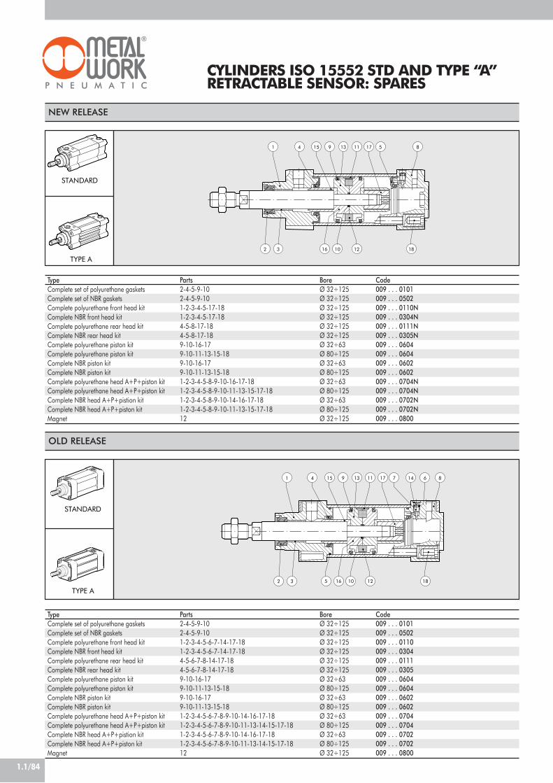
1.1/84
CYLINDERS ISO 15552 STD AND TYPE “A”RETRACTABLE SENSOR: SPARES
2 10
5
3
1 4
TYPE A
STANDARD
15 9 13 11 17 8
16 12 18
TypeComplete set of polyurethane gasketsComplete set of NBR gasketsComplete polyurethane front head kitComplete NBR front head kitComplete polyurethane rear head kitComplete NBR rear head kitComplete polyurethane piston kitComplete polyurethane piston kitComplete NBR piston kitComplete NBR piston kitComplete polyurethane head A+P+piston kitComplete polyurethane head A+P+piston kitComplete NBR head A+P+pistion kitComplete NBR head A+P+piston kitMagnet
Parts2-4-5-9-102-4-5-9-101-2-3-4-5-17-181-2-3-4-5-17-184-5-8-17-184-5-8-17-189-10-16-179-10-11-13-15-189-10-16-179-10-11-13-15-181-2-3-4-5-8-9-10-16-17-181-2-3-4-5-8-9-10-11-13-15-17-181-2-3-4-5-8-9-10-14-16-17-181-2-3-4-5-8-9-10-11-13-15-17-1812
BoreØ 32÷125Ø 32÷125Ø 32÷125Ø 32÷125Ø 32÷125Ø 32÷125Ø 32÷63Ø 80÷125Ø 32÷63Ø 80÷125Ø 32÷63Ø 80÷125Ø 32÷63Ø 80÷125Ø 32÷125
Code009 . . . 0101009 . . . 0502009 . . . 0110N009 . . . 0304N009 . . . 0111N009 . . . 0305N009 . . . 0604009 . . . 0604009 . . . 0602009 . . . 0602009 . . . 0704N009 . . . 0704N009 . . . 0702N009 . . . 0702N009 . . . 0800
NEW RELEASE
STANDARD
TYPE A2 183
17
12
13 87 6
16
14
5
9
10
111541
TypeComplete set of polyurethane gasketsComplete set of NBR gasketsComplete polyurethane front head kitComplete NBR front head kitComplete polyurethane rear head kitComplete NBR rear head kitComplete polyurethane piston kitComplete polyurethane piston kitComplete NBR piston kitComplete NBR piston kitComplete polyurethane head A+P+piston kitComplete polyurethane head A+P+piston kitComplete NBR head A+P+pistion kitComplete NBR head A+P+piston kitMagnet
Parts2-4-5-9-102-4-5-9-101-2-3-4-5-6-7-14-17-181-2-3-4-5-6-7-14-17-184-5-6-7-8-14-17-184-5-6-7-8-14-17-189-10-16-179-10-11-13-15-189-10-16-179-10-11-13-15-181-2-3-4-5-6-7-8-9-10-14-16-17-181-2-3-4-5-6-7-8-9-10-11-13-14-15-17-181-2-3-4-5-6-7-8-9-10-14-16-17-181-2-3-4-5-6-7-8-9-10-11-13-14-15-17-1812
BoreØ 32÷125Ø 32÷125Ø 32÷125Ø 32÷125Ø 32÷125Ø 32÷125Ø 32÷63Ø 80÷125Ø 32÷63Ø 80÷125Ø 32÷63Ø 80÷125Ø 32÷63Ø 80÷125Ø 32÷125
Code009 . . . 0101009 . . . 0502009 . . . 0110009 . . . 0304009 . . . 0111009 . . . 0305009 . . . 0604009 . . . 0604009 . . . 0602009 . . . 0602009 . . . 0704009 . . . 0704009 . . . 0702009 . . . 0702009 . . . 0800
OLD RELEASE

1.1/85
1
ACCESSORIES:GUIDE UNITS FOR CYLINDERS ISO 15552STD AND TYPE “A” RETRACTABLE SENSOR
GUIDE UNIT ELEMENTS
Guide units series DS-DH-DM ensure optimal alignmentand anti-rotation effect of the pneumatic cylinder connectedto it. The guide units can be used separately or combinedin order to get complete handling units, in which case theguide units can be coupled using the type A and Canchorage (pin and flange).The guide units can be coupled to ISO 15552 cylinders(Ø 32 - Ø 100). The following versions are available:U PROFILE*: for limited loads and speeds (GDS)H PROFILE*: for high loads (GDH)H PROFILE**: for high speeds (GDM)
STANDARD STROKES:Ø 32-100: 50-100-150-200-250-320-400-500
**Bronze guide bushings**Ball guide bushings(For weights, refer to the data sheet on page 1.1/06)
SERIES GDS-GDH
SERIES GDM
Body:Guide bushing:Piston rod:Body:Guide bushing:Piston rod:
aluminium alloyself-lubricating sintered bronze and wiper ringschromed rolled steelaluminium alloyball linear bearings and scraper ringtempered stainless steel
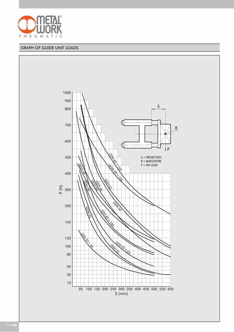
1.1/86
300
50 100 150 200 250 300 600
800
600
500
700
200
100
350 400 450 500 550
120
50
900
160
80
30
10
400
1000
P
BG
DH 80 • 100
GDM
80 • 100GDH 63
GDH 50
GD
H 40
GD
M 63
GD
M 50
GDS 80 • 100
GD
M 40
GDS 50 • 63
GDH 32
GD
M 32
GDS 32 • 40
P (N
)
S (mm)
S
GRAPH OF GUIDE UNIT LOADS
S = PROJECTIONB = BARYCENTREP = PAY LOAD

1.1/87
1DIMENSIONS TYPE GDS
X
F
F2 depth 10
F2 depth 10
CH
Y
F
D*
F
F1
GE1 O C1
E3
N ML1+
B1I
øS
C
O1E
E
L+
A1
H
BE2
E
A
E
DIMENSIONS TYPE GDH-GDM
F
FCH
F1
D*
F2 depth 10
F
F2 depth 10
Y
X
E
B
O
U
L1+ N M
IE
E
C1
L+
C
E
H
A
E3
A1øS
B1
E
E2
G
+ = ADD THE STROKE! CENTERING PINHOLES
+ = ADD THE STROKE! CENTERING PINHOLES
Ø3240506380100
A4856667698118
A1
4553637395115
B100106125132165185
C4858597690110
C1
121515151616
DH7
666666
E32.53846.556.57289
E1
32.53846.556.55070
E2
7884100105130150
E3
58648095130150
FM6M6M8M8M10M10
F1
6.56.58.58.51111
G182124243131
H313645455656
I748096104130152
L108120130145170190
L1
94105106121128138
M465265657171
N172125253439
O7.8106.39.82020
O1
7.8106.39.8910.5
Ø S121216162020
Ch151522222727
B1
95101120127160180
Ø3240506380100
B97115137152189213
B1
90110130145180200
A49586985105129
C125139148182215220
C1
121515152020
DH7
666666
E32.53846.556.57289
E2
7884100105130150
O4.31118.515.32124.5
E3
616985100130150
FM6M6M8M8M10M10
F1
6.56.58.58.51111
G182124243131
H313645455656
I7487104119148172
L177192205237280280
L1
94105106121128138
M475363627676
N172126263439
Ø S121620202525
A1
4554637999120
Ch131522222727
U768178111128128
VIEW X-Y
VIEW X-Y
F2H7
666666
F2H7
666666
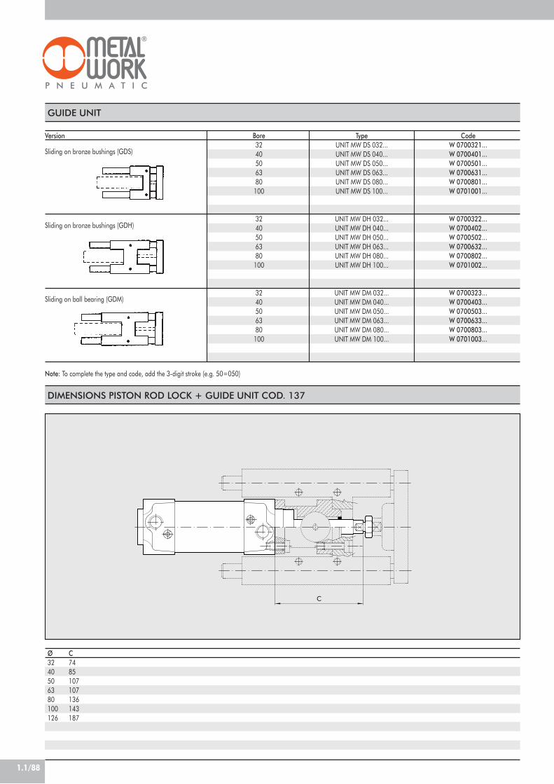
1.1/88
DIMENSIONS PISTON ROD LOCK + GUIDE UNIT COD. 137
C
Ø3240506380100126
C7485107107136143187
GUIDE UNIT
Sliding on bronze bushings (GDS)
Sliding on bronze bushings (GDH)
Note: To complete the type and code, add the 3-digit stroke (e.g. 50=050)
Sliding on ball bearing (GDM)
TypeUNIT MW DS 032...UNIT MW DS 040...UNIT MW DS 050...UNIT MW DS 063...UNIT MW DS 080...UNIT MW DS 100...
UNIT MW DH 032...UNIT MW DH 040...UNIT MW DH 050...UNIT MW DH 063...UNIT MW DH 080...UNIT MW DH 100...
UNIT MW DM 032...UNIT MW DM 040...UNIT MW DM 050...UNIT MW DM 063...UNIT MW DM 080...UNIT MW DM 100...
CodeW 0700321...W 0700401...W 0700501...W 0700631...W 0700801...W 0701001...
W 0700322...W 0700402...W 0700502...W 0700632...W 0700802...W 0701002...
W 0700323...W 0700403...W 0700503...W 0700633...W 0700803...W 0701003...
Bore3240506380
100
3240506380
100
3240506380
100
Version

1.1/89
1
CYLINDER SERIES ISO 15552(EX ISO 6431), Ø 32-63 mm TWO-FLAT
COMPONENTS
! PISTON ROD: stainless steel." HEAD: die cast aluminium, fully machined# PISTON ROD GASKET: polyurethane$ GUIDE BUSHING: sintered bronze% BARREL: drawn anodised calibrated aluminium& HALF-PISTON: self-lubricating technopolymer withbuilt-in cushioning olives' PISTON GASKET: Ø 32÷63 polyurethane( MAGNET: plastoferrite) Static O-rings: NBR* CUSHIONING GASKET: polyurethane+ CUSHIONING NEEDLE: OT 58 with needle outmovement safety system even when fully open, SCREWS: Tap Tite for assembly
4 1023 5 6 8 7 12111 9
This version of cylinder is used to keep the parts fixed to thepiston rod at an angle and to apply torques within thespecified limits.The piston rod of the Two Flat has two opposing longitudinalsurfaces; it is made of stainless steel.The front cylinder head includes a sintered bronze bush thatmatches the profile of the piston rod and prevents it fromrotating on its own axis. A special polyurethane gasketensures pneumatic seal and prevents the accumulation ofdirt. This technical solution is more reliable and gives a betterpneumatic seal than with square or hexagonal piston rods.The cylinders are made to ISO15552 standards. They areavailable in several versions and with a wide range ofaccessories:• with or without magnet• double acting, single piston rod• double acting, through rod; one piston rod is Two Flat,
the other cylindrical• fixing accessories.
POLYURETHANE
max 10 bar (max 1 MPa - 145 psi)–20 ÷+80 (non-magnetic cyl.)
–20 ÷+70 (magnetic cyl.))Unlubricated air. Lubrication, if used, must be continuous
Ø 32 ; Ø 40 ; Ø 50 ; Ø 63Heads with Tap Tite screws
Ø 32= 300 Ø 40= 400 Ø 50= 500 Ø63= 500! Maximum recommended strokes. Higher values can create operating problems
Double-acting cushioned, Through-rod cushioned, no-stick slip*All versions come complete with magnet. Supplied without magnet on request.
Ø 32= 0.4 Ø 40= 0.4 Ø 50= 0.3 Ø63= 0.3Ø 32= 0.2 Ø 40= 0.4 Ø 50= 1 Ø63= 1
Ø 32= 0.70° Ø 40= 0.75° Ø 50= 0.65° Ø63= 0.65°See GENERAL TECHNICAL DATA PAGE 1.1/05See GENERAL TECHNICAL DATA PAGE 1.1/06
*Using for speeds lower than 0.2m/s, to prevent surging.For no-stick-slip versions use no-lubricated air only
TECHNICAL DATAOperating pressureTemperature range
°CFluidBoreDesignMaximun stroke ! mm
VersionsSensor magnetInrush pressureMax torque on piston rod NmMaximum rotation on the rod degreesForces generated at 6 bar thrust/retractionWeights

1.1/90
DIMENSIONS OF STANDARD VERSIONS
1
0
121
120
CH1
B
E
CH
2
H
L +
L +
C 1
CF
M
N
E 1
L +
Q
D 2
GP
A 2
BD
A
A 1
G 1
E H
D 1
Ø.32405063
+ = ADD THE STROKE
A10121416
A1
791414
A2
10101010
B30354045
C26303737
C1
16202525
CH10131717
CH1
6688
DM10x1.25M12x1.25M16x1.5M16x1.5
D1
12162020
D2
15191923
E32.53846.556.5
E1
5555
F22243232
GG1/8G1/4G1/4G3/8
G1
M6M6M8M8
H47536575
L120135143158
L0
94105106121
L1
74817889
L2
146165180195
M991212
N4.54.55.55.5
P6666
Q4466
DIMENSIONS OF THROUGH-ROD VERSION
2
122
1CH
2
0
1
CH
E HC
HF
G 1
L +
L +
L ++
C +
D 2
G
QP
C 1M
N
D1
D
C F
A 2
B
A
A 1
E
H
D 1
+ = ADD THE STROKE++= ADD TWICE THE STROKE
CH2
10131717

1.1/91
1
INTERMEDIATE HINGE - MODEL EN
TL
X MIN
XV+1/2
X+ MAX
TK
TD
UW
TLTM
Code
0950322007095040200709505020070950632007
Ø
32405063
COUNTER-HINGE FOR MODEL EN - MODEL EL
A
HB
A1 ±0.2
øL
E
C
C±
0.1
D1 D H7
D2
Cod.
W0950322009W0950402009W0950402009W0950632009
Ø
32405063
A
46555565
A1
32363642
B
18212123
C
30363640
C1
15181820
D2
79911
D
12161620
D1
11151518
E
6.58.58.510.5
+ = ADD THE STROKE+ 1/2 = ADD HALF THE STROKE
NOTE: Supplied with 4 securing screws
H
10.5121213
ØL
22282835
Weight [g]
2825828801230
Note: Supplied complete with 4 grub screws, 2 pins
Weight [g]
162278278414
ACCESSORIES: FIXINGS
KEY TO CODES
CYL 1 2 1
120 Double-acting,cuschioned,
non-magnetic121 Double-acting,
cushioned122 Through-rod
0
0 DiameterS Non-
magneticG No stick slip
3 2
32 40 50 63
0 0 5 0
! Ø32 stroke 0÷300 mm
! Ø40stroke 0÷400 mm
! Ø50÷Ø63stroke 0÷500 mm
F
F “Two Flat”piston rod
AISI 303stainless steel
nut
TYPE BORE STROKE
P
P polyurethanegaskets
! Maximum recommended strokes. Higher values can create operating problems
X (min)
63728386.5
XV
7382.59097.5
X (max)
839397108.5
TM
50637590
TL
12161620
TD e 9
12161620
TK
22283235
UW
657595105
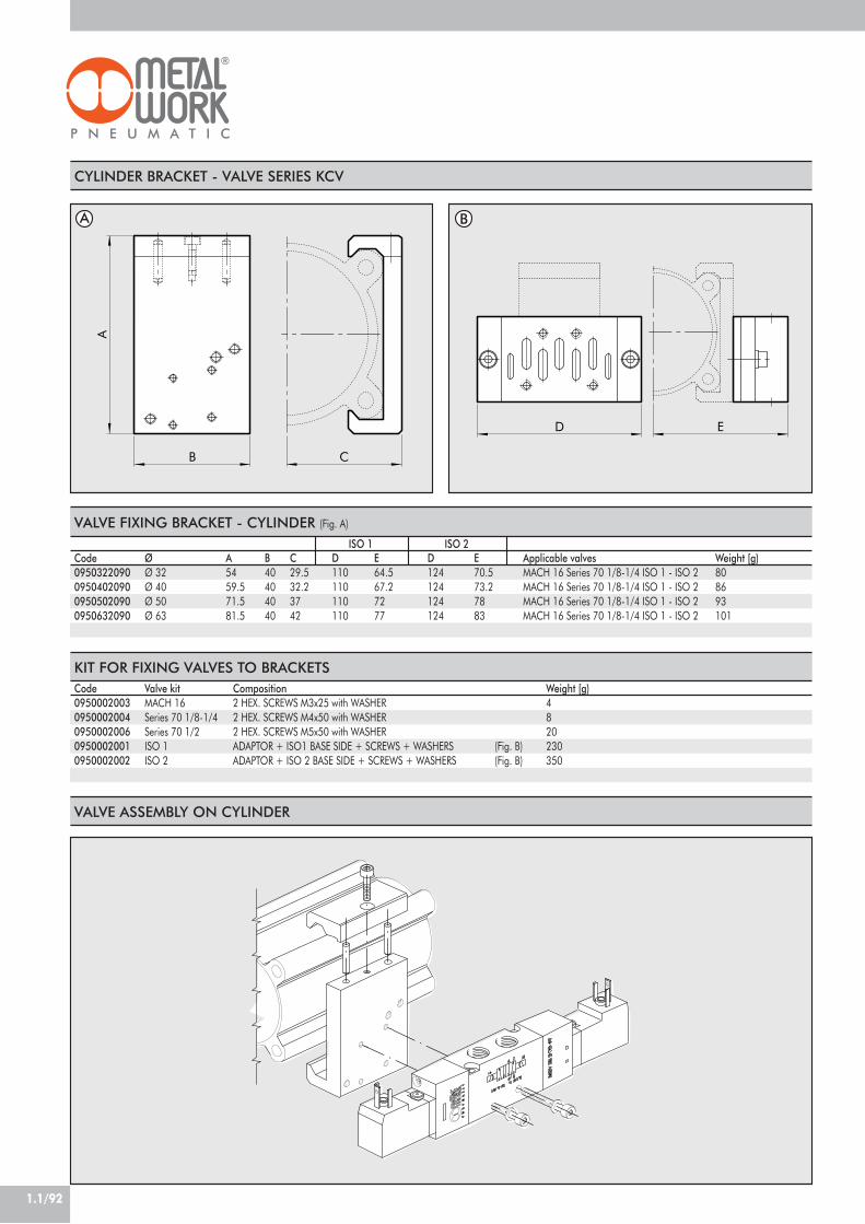
1.1/92
KIT FOR FIXING VALVES TO BRACKETS
Code0950322090095040209009505020900950632090
ØØ 32Ø 40Ø 50Ø 63
A5459.571.581.5
B40404040
C29.532.23742
D110110110110
E64.567.27277
D124124124124
E70.573.27883
Applicable valvesMACH 16 Series 70 1/8-1/4 ISO 1 - ISO 2MACH 16 Series 70 1/8-1/4 ISO 1 - ISO 2MACH 16 Series 70 1/8-1/4 ISO 1 - ISO 2MACH 16 Series 70 1/8-1/4 ISO 1 - ISO 2
Code09500020030950002004095000200609500020010950002002
Valve kitMACH 16Series 70 1/8-1/4Series 70 1/2ISO 1ISO 2
Composition2 HEX. SCREWS M3x25 with WASHER2 HEX. SCREWS M4x50 with WASHER2 HEX. SCREWS M5x50 with WASHERADAPTOR + ISO1 BASE SIDE + SCREWS + WASHERS (Fig. B)ADAPTOR + ISO 2 BASE SIDE + SCREWS + WASHERS (Fig. B)
CYLINDER BRACKET - VALVE SERIES KCV
B
A
C
D E
VALVE FIXING BRACKET - CYLINDER (Fig. A)
ISO 1 ISO 2
A B
VALVE ASSEMBLY ON CYLINDER
Weight [g)4820230350
Weight [g)808693101

1.1/93
1
ACCESSORIES: MAGNETIC SENSORS
9.1
11.5
25.534
17
SENSOR BRACKETS
SENSORCodeW0950000201W0950000222W0950000232
N.B.: for tecnical data on sensor, see page 1.1/71
DescriptionSENSOR REED DSM2-C525 HSSENSOR HALL PNP DSM3-N225SENSOR HALL NPN DSM3-M225
Ø 32÷40
13.2
2.7
18.5
M5
5.9
19.2
14
29.5 29.8
14.8 1.8
20.9
14
M5
20.4
1.6
25.9
Ø 50÷63
CodeW0950000711
DescriptionBRACKET ACC. D.32 DST 80
CodeW0950000712
DescriptionBRACKET ACC. D.50 DST 81
ADAPTOR FOR RETRACTABLE SENSOR
DescriptionAdaptor DSS005 for DST/ST brackets
CodeW0950001001
ASSEMBLY DIAGRAM
45
3
2 1
! ISO 15552 cylinder with traditional barrel" Sensor bracket mod. DST (Ø32÷125)# Adaptor$ Retractable sensor with insertion from above% Retractable sensor

1.1/94
CYLINDERS SERIES “ISO 15552(EX ISO 6431)” Ø 32-63 mm TYPE “A”RETRACTABLE SENSOR TWO FLAT
JACKET CROSS SECTION
This version of cylinder is used to keep the parts fixed tothe piston rod at an angle and to apply torques within thespecified limits.Type A cylinders have a jacket with grooves for housingretractable sensors.The piston rod of the Two Flat has two opposing longitudinalsurfaces; it is made of stainless steel.The front cylinder head includes a sintered bronze bushthat matches the profile of the piston rod and prevents itfrom rotating on its own axis. A special polyurethane gasketensures pneumatic seal and prevents the accumulation ofdirt. This technical solution is more reliable and gives abetter pneumatic seal than with square or hexagonal pistonrods.The cylinders are made to ISO15552 standards. They areavailable in several versions and with a wide range ofaccessories:• with or without magnet• double acting, single piston rod• double acting, through rod; one piston rod is Two Flat,
the other cylindrical• fixing accessories.
TECHNICAL DATA POLYURETHANE
max 10 bar (max 1 MPa - 145 psi)–20 ÷+80 (non-magnetic cyl.)
–20 ÷+70 (magnetic cyl.))Unlubricated air. Lubrication, if used, must be continuous
Ø 32 ; Ø 40 ; Ø 50 ; Ø 63Heads with Tap Tite screws
Ø 32= 300 Ø 40= 400 Ø 50= 500 Ø63= 500! Maximum recommended strokes. Higher values can create operating problems
Double-acting cushioned, Through-rod cushioned, no-stick slip*All versions come complete with magnet. Supplied without magnet on request.
Ø 32= 0.4 Ø 40= 0.4 Ø 50= 0.3 Ø63= 0.3Ø 32= 0.2 Ø 40= 0.4 Ø 50= 1 Ø63= 1
Ø 32= 0.70° Ø 40= 0.75° Ø 50= 0.65° Ø63= 0.65°See GENERAL TECHNICAL DATA PAGE 1.1/05See GENERAL TECHNICAL DATA PAGE 1.1/06
*For no-stick slip versions, use no-lubricated air only
Operating pressureTemperature range
°CFluidBoreDesignMaximun stroke ! mm
VersionsSensor magnetInrush pressureMax torque on piston rod NmMaximum rotation on the rod degreesForces generated at 6 bar thrust/retractionWeights
1
Ø63
Ø32 Ø40
11
1
Ø50
31.9
74
31.9
74
44.5
13.3
44.5
6.6
53 18.4
53
18.4
63.3
23.5
23.5
63.3
! SLOTS FOR RETRACTABLE SENSOR
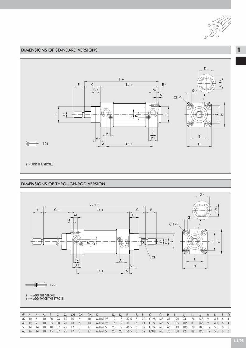
1.1/95
1DIMENSIONS OF STANDARD VERSIONS
1
0
121
CH1
B
E
CH
2
H
L +
L +
C 1
CF
M
N
E 1
L +
Q
D 2
GP
A 2
BD
A
A 1
G 1
E H
D 1
Ø32405063
+ = ADD THE STROKE
A10121416
A1
791414
A2
10101010
B30354045
C26303737
C1
16202525
CH10131717
CH1
6688
DM10x1.25M12x1.25M16x1.5M16x1.5
D1
12162020
D2
15191923
E32.53846.556.5
E1
5555
F22243232
GG1/8G1/4G1/4G3/8
G1
M6M6M8M8
H47536575
L120135143158
L0
94105106121
L1
74817889
L2
146165180195
M991212
N4.54.55.55.5
P6666
Q4466
DIMENSIONS OF THROUGH-ROD VERSION
2
122
1CH
2
0
1
CH
E HC
HF
G 1
L +
L ++
C +
D 2
G
QP
C 1M
N
D1
D
C F
A 2
B
A
A 1
E
H
D 1
L +
+ = ADD THE STROKE++= ADD TWICE THE STROKE
CH2
10131717

1.1/96
F “Two Flat”piston rod
AISI 303stainless steel
nut
P polyurethanegaskets
KEY TO CODES
CYL 1 2 1
121 Double-acting,cushioned
122 Through-rod
A StandardB No stick slipC Non-
magnetic
TYPE DIAMETER STROKE
3 2
32 40 50 63
0 0 5 0
! Ø32stroke 0÷300 mm
! Ø40stroke 0÷400 mm
! Ø50÷Ø63 stroke 0÷500 mm
F PA
! Maximum recommended strokes. Higher values can create operating problems
ACCESSORIES: FIXINGS
INTERMEDIATE HINGE - MODEL EN
UW
X+ MAX
TMTL
TL
TK TD
X MIN
XV+1/2
Code
0950322107095040210709505021070950632107
Ø
32405063
X (min)
63728386.5
XV
7382.59097.5
X (max)
839397108.5
TM
50637590
TL
12161620
COUNTER-HINGE FOR MODEL EN - MODEL EL
A
HB
A1 ±0.2
øL
E
C
C±
0.1
D1 D H7
D2
Code
W0950322009W0950402009W0950402009W0950632009
Ø
32405063
A
46555565
TD e 9
12161620
TK
22282836
UW
657595105
A1
32363642
B
18212123
C
30363640
C1
15181820
D2
79911
D
12161620
D1
11151518
E
6.58.58.510.5
+ = ADD THE STROKE+ 1/2 = ADD HALF THE STROKE
Note: Supplied with 4 securing screws
H
10.5121213
ØL
22282835
Weight [g]
170360580950
Note: Supplied complete with 4 grub screws, 2 pins
Weight [g]
162278278414

1.1/97
1VALVE ASSEMBLY ON CYLINDER
With this type of cylinder, the valves (D) canbe mounted directly using the retractingsensor slot, without requiring the use ofintermediate brackets.This can be done using the special plates(A), which come with both the M3 and M4threads, and screws (B) of the size, typeand quantity shown in the table below.For ISO 1 and ISO 2 valves, the kit onwhich the valve is to be mounted (codesshown in the tables) will be fitted to thecylinder using the special plates (A) andthe screws (B) listed in the table.
Type of valveto mount (D)
MACH 11SERIE 70 1/8SERIE 70 1/4SERIE 70 1/2ISO 1ISO 2
M3 fixingplate (A)
code 0950003002n° 2
–––––
M4 fixingplate (A)
code 0950003001–
n° 2n° 2n° 2n° 2n° 2
Screw (B)for connection to cylinder
(one per plate)M3x16 UNI 5931 (DIN 912)M4x25 UNI 5931 (DIN 912)M4x30 UNI 5931 (DIN 912)M4x45 UNI 5931 (DIN 912)M4x8 UNI 7688 (DIN 965A)M4x8 UNI 7688 (DIN 965A)
Washer (B)(one per screw)
A3.2 UNI 1751 (DIN 127A)–
A4.3 UNI 1751 (DIN 127A)A4.3 UNI 1751 (DIN 127A)
––
Valveassembly
kit––––
09500020010950002002
ABD
NOTE

1.1/98
ACCESSORIES: MAGNETIC SENSORSRETRACTABLE SENSOR WITH INSERTIONFROM ABOVE Description
HALL N.O. SENSOR, VERTICAL INSERTION 2.5mHALL N.O. SENSOR, VERTICAL INSERTION 300 mm M8REED N.O. SENSOR, VERTICAL INSERTION 2.5mREED N.O. SENSOR, VERTICAL INSERTION 300 mm M8HALL N.O. SENSOR, VERTICAL INSERTION 2m ATEX
Code
W0952025390W0952029394W0952022180W0952028184W0952125556
This type of sensor can be inserted in the slot of the sensor from above. This means thecylinder heads do not require a through opening.
WIRING DIAGRAM TECHNICAL DATA
Type of contactSwitchSupply voltage (Ub) VPower WVoltage variationVoltage drop VInput current mAOutput current mASwitching frequency HzShort-circuit protectionOver-voltage suppressionPolarity inversion protectionEMCLED displayMagnetic sensitivityRepeatabilityDegree of protection (EN 60529)Vibration and shock resistanceTemperature range °CSensor capsule material2.5m/2m connecting cableConnecting cable with M8x1Wire NO.
Reed Effetto Hall Effetto HallN.O. N.O. N.O.
- PNP PNP10 ÷ 30 AC/DC 10 ÷ 30 DC 18 ÷ 30 DC3 (peak valve=6) 3 ! 1.7
- ! 10% di Ub ! 10% di Ub- ! 2 ! 2.2- ! 10 ! 10
! 100 ! 100 ! 70! 400 ! 5000 1000
- Yes Yes- Yes Yes- Yes Yes
EN 60 947-5-2 EN 60 947-5-2 EN 60 947-5-2Yellow Yellow Yellow
2,8 mT ±25% 2,8 mT ±25% 2.6! 0,1 mT ! 0,1 mT ! 0,1 (Ub and ta fixed)
IP 67 IP 67 IP 68, IP 69K30 g, 11 ms, 10÷55 Hz, 1mm 30 g, 11 ms, 10÷55 Hz, 1mm 30 g, 11 ms, 10÷55 Hz, 1mm -25 ÷+75 -25 ÷ +75 -20 ÷ +45
PA66 + PA6I/6T PA66 + PA6I/6T PAPVC; 2 x 0,12 mm2 PVC; 3 x 0,14 mm2 PVC; 3 x 0,12 mm2
Polyurethane; 2 x 0,14 mm2 Polyurethane; 3 x 0,14 mm2 -2 3 3
ATEX
5.8 500
4.9
STRIP
DescriptionSLOT STRIP 500 mm
CodeW0950000160
Note: The code corresponds to 1 piece.
KIT FOR CYLINDER ASSEMBLYWITH SENSOR SLOTS Description
ACC. M4 T-SLOTTED FIXING PLATEACC. M3 T-SLOTTED FIXING PLATE
Code
09500030010950003002
Note: Individually packed
Weight [g]
11
black
HALL EFFECT+
+
brown
blue
PNP
blue
black
-
blue
brown
brown
34
1
REED EFFECT+
+-
brown
3blue 4
1
M8
M8

1.1/99
1
ACCESSORIES ISO 15552 STD AND TYPE “A”RETRACTABLE SENSOR TWO-FLAT: FIXINGS
2
1
AH
AU
AO
øAB
AT
UH
TR
H +
H +
Code
W0950322001W0950402001W0950502001W0950632001
Ø
32405063
Ø AB
7999
AH
32364550
AO
35434747
AT
4446
AU
24283232
TR
32364550
UH
45526575
H1
144163175190
H2
142161170185
Weight [g]
76100162266
Note: Individually packed with 2 screws.
LEGS - MODEL A
+= ADD THE STROKE
R
3
H9
E
B
D
S
H +
øG
Code
W0950322003W0950402003W0950502003W0950632003
Ø
32405063
B
45526070
D
26283240
E
22252732
Ø G
10121216
H3
142160170190
R
11131317
S
10101212
øG H
9
Weight [g]
116160252394
Note: Supplied with 4 screws, 4 washers, 2 snap-rings, 1 pin.
FEMALE HINGE - MODEL B
+= ADD THE STROKE
FH
9
3
E
øG
H
D
H +
Code
W0950322004W0950402004W0950502004W0950632004
Ø
32405063
D
26283240
E
22252732
F
11131317
Ø G
10121216
H
10101212
H3
142160170190
Weight [g]
94124220316
Note: Supplied with 4 screws, 4 washers
MALE HINGE - MODEL BA
+= ADD THE STROKE
F
3
N
M
E
H
H +
Code
W0950322006W0950402006W0950502006W0950632006
Ø
32405063
E
22252732
F
16191924
H
10101212
H3
142160170190
M
10121216
N
14161621
Weight [g]
106142236336
Note: Supplied with 4 screws, 4 washers
ARTICULATED MALE HINGE - MODEL BAS
+= ADD THE STROKE

1.1/100
I
LF
C
A
E
G
N
B
M
H
D
Code
W0950322008W0950402008W0950502008W0950632008
Ø
32405063
A
26283240
B
19262633
C
79911
D
10121216
E
25323240
F
20323250
G
32454563
H
37545475
I
41525263
L
18252532
M
8101012
N
10121215
Weight [g]
96216212440
Note: Supplied with 4 screws, 4 washers
CETOP COUNTER-HINGE FOR MODEL BMODEL GL
J
B G
CD
M
N
C
D
E
L
Code
W0950322108W0950402108W0950502108W0950632108
Ø
32405063
B
25.527.531.539.5
C
32.53846.556.5
D
45526575
E
7799
G
32364550
J
11131317
L
10101212
M
10121216
N
10121215
Weight [g]
106138252350
Note: Supplied with 4 screws, 4 washers
ISO COUNTER-HINGE FOR MODEL BMODEL GS
øD
A1
B
B1
A
W S
Code
W0950322002W0950402002W0950502002W0950632002
Ø
32405063
A1
647290100
A
8090110120
B
50556575
S
10101212
B1
32364550
ØD4
7999
W
16202525
Weight [g]
246290522670
Note: Supplied with 4 screws.
FRONT FLANGE - MODEL C
A
B1
B L+
A1
øD
S
Code
W0950322002W0950402002W0950502002W0950632002
Ø
32405063
A1
647290100
A
8090110120
B
50556575
S
10101212
B1
32364550
ØD4
7999
L+corsa
130145155170
Weight [g]
246290522670
Note: Supplied with 4 screws.
+= ADD THE STROKE
REAR FLANGE - MODEL C
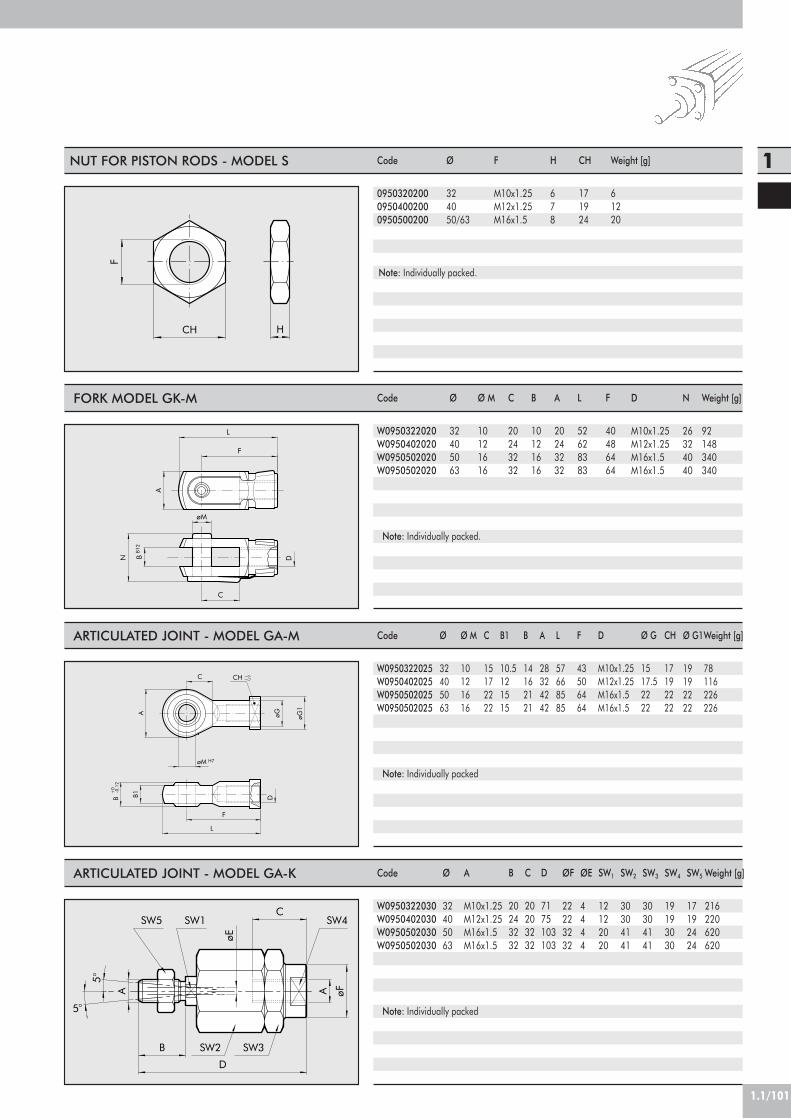
1.1/101
1
H
F
CH
Code
095032020009504002000950500200
Ø
324050/63
F
M10x1.25M12x1.25M16x1.5
H
678
CH
171924
Weight [g]
61220
Note: Individually packed.
NUT FOR PISTON RODS - MODEL S
B12
øM
F
L
B
A
C
DN
Code
W0950322020W0950402020W0950502020W0950502020
H7
CH
-0.1
2+
0
B1
F
L
D
C
A
øM
B
øG øG1
5°
5°
SW4SW5
SW3
SW1
SW2B
D
A A øF
C
øE
Code
W0950322030W0950402030W0950502030W0950502030
Ø
32405063
A
M10x1.25M12x1.25M16x1.5M16x1.5
Ø
32405063
Ø M
10121616
C
20243232
B
10121616
A
20243232
L
52628383
F
40486464
B
20243232
C
20203232
D
7175103103
SW1
12122020
SW2
30304141
ØF
22223232
D
M10x1.25M12x1.25M16x1.5M16x1.5
Code
W0950322025W0950402025W0950502025W0950502025
Ø
32405063
Ø M
10121616
C
15172222
B1
10.5121515
B
14162121
A
28324242
D
M10x1.25M12x1.25M16x1.5M16x1.5
F
43506464
Ø G
1517.52222
CH
17192222
SW3
30304141
SW4
19193030
SW5
17192424
L
57668585
N
26324040
Ø G1
19192222
Weight [g]
92148340340
Weight [g]
78116226226
Weight [g]
216220620620
ØE
4444
FORK MODEL GK-M
ARTICULATED JOINT - MODEL GA-M
ARTICULATED JOINT - MODEL GA-K
Note: Individually packed.
Note: Individually packed
Note: Individually packed

1.1/102
CYLINDERS ISO 15552 STD AND TYPE “A”RETRACTABLE SENSOR TWO-FLAT: SPARES
1
9
42
16
3
1817 19
51115 1213 10 7 8614
TypeComplete set of polyurethane gasketsComplete polyurethane front head kitComplete polyurethane rear head kitComplete polyurethane piston kitComplete polyurethane head A+P+piston kitMagnet
Parts2-4-5-6-9-101-2-3-4-5-6-7-14-17-184-5-6-7-8-14-17-189-10-16-191-2-3-4-5-6-7-8-9-10-14-16-17-1812
BoreØ 32÷63Ø 32÷63Ø 32÷63Ø 32÷63Ø 32÷63Ø 32÷63
Code009 . . . 0101F009 . . . 0110F009 . . . 0111009 . . . 0604009 . . . 0704F009 . . . 0800

CYLINDER SERIES ISO 15552 (EX ISO 6431),Ø 160-200 mm WITH ROUND BARREL
TECHNICAL DATA
Cylinders made to ISO 15552 available in various versionsand with a wide range of accessories:• Configuration with or without magnet• Double-acting – single- or through-rod• NBR gaskets or FKM/FPM (high temperature)• Available with mounted intermediate hinge• Special configurations on request
Operating pressureTemperature rangeFluid temperatureDesignMaterials
Forces generated at 6 bar (tensile stress)Standard strokesWeight
PTeTf
mm
max 10 b ar (1 MPa)–10°C to +70°C–10°C to +70°CRound barrel with tie rodsHeads: die cast aluminiumPiston rod: thick chromed steelJacket: aluminiumPiston: aluminium with technopolimer guide beltGaskets: NBR or FKM/FPMSee GENERAL TECHNICAL DATA PAGE 1.1/0525-50-75-80-100-125-150-200-250-300-350-400-500-600-700-800-900-1000See GENERAL TECHNICAL DATA PAGE 1.1/06
1.1/103
1
COMPONENTS
! PISTON ROD: C45 steel or stainless steel, thick chromed
" HEAD: die cast aluminium# PISTON ROD GASKET: NBR or FKM/FPM$ GUIDE BUSHING: sintered bronze% BARREL: drawn anodised aluminium alloy& PISTON: aluminium' PISTON GASKET: NBR or FKM/FPM( MAGNET: plastoferrite) CUSHIONING CAP: aluminium* CUSHIONING GASKET+ Static O-rings: NBR or
FKM/FPM+ CUSHIONING NEEDLE: OT 58 with needle out
movement safety system even when fully open, SCREWS: galvanised steel- TIE RODS: galvanised steel. GUIDE BELT: technopolimer
3
14 11
4
2 8
12 13
10 57
1
6 9

1.1/104
3
55W122
W123
L1 +
L ++
Q+
G3/
4
M16
DB
M36
x2
72 Q
G
K
20
180 +
22.5
22.5
øCø40
14
2
55W120
W121
W124 B
D
B D
M16
22.5
22.5
L +
180 +
20
K
G
Q72
M36
x2
øE
øCø40
G3/
4
L1 +
14
DIMENSIONS OF STANDARD VERSION
DIMENSIONS OF THROUGH-ROD VERSION
Ø160200
B180220
Ø C6575
Ø E6575
D140175
G5060
L2
260275
L3
338370
Q8095
+ = ADD THE STROKE
+ = ADD THE STROKE++= ADD TWICE THE STROKE
K2829
L1
124122
W120
W121
W124
I
S
øF
Q
min H1
L2 +
max H2 +
E
DIMENSIONS OF VERSION WITH INTERMEDIATE HINGE
Ø160200
E200250
Ø F3232
H1150165
H2190205
I3232
L2260275
Q8095
S4040
+ = ADD THE STROKE
For the missing values, refer to standard cylinders.In your order, please specify the desired value for H1

1.1/105
1
An alternative to the round barrel version is a version with ashaped barrel.The technical data, components and dimensions are the sameas for the round barrel version
Note: Type with intermediate hinge not available
KEY TO CODES FOR SHAPED BARREL
CYL 1 2 1
120 Double-acting,cuschioned,
non-magnetic121 Double-acting,
cushioned122 Through-rod124 Double-acting,
non-cuschioned
TYP160200
SA3 160 ohne Magnet
SA4 200 ohne Magnet
DURCHMESSERA N
N NBRgaskets
V FKM/FPMgaskets
+ 0025÷2800 mmHUBLÄNGE
A C45 chromed piston rod,Z Stainless steel chromed,
piston rod
1 6 0 0 0 5 0
VERSION WITH SHAPED BARREL
! Maximum recommended strokes. Higher values can create operating problems
KEY TO CODES FOR ROUND BARREL
CYL W 1 2 1
W120 Double-acting,cylinder cushioned,
non magneticW121 Double-acting
cylinder, cushionedW122 Double-acting
cylinder, cushioned,through-rod
W123 Double-actingcylinder, cushioned,
through-rod, non magneticW124 Double-acting
cylinder, non-cushioned
TYPE160200
XA3 160 stainless steelpiston rod
XA4 200 stainless steelpiston rod
VA3 160 FKM/FPM gasket,stainless steel piston rod
VA4 200 FKM/FPM gasket,stainless steel piston rod
KA3 160 FKM/FPM gasket,C45 piston rod
KA4 200 FKM/FPM gasket,C45 piston rod
AA3 160+intermediate hingeAA4 200+intermediate hinge
DIAMETER-EXECUTION! 0025÷2800 mm
STROKE
! Maximum recommended strokes. Higher values can create operating problems
Specify H1 value ONLYfor version withintermediate hinge
1 6 0 0 0 5 0 0 2 0 0EXECUTION
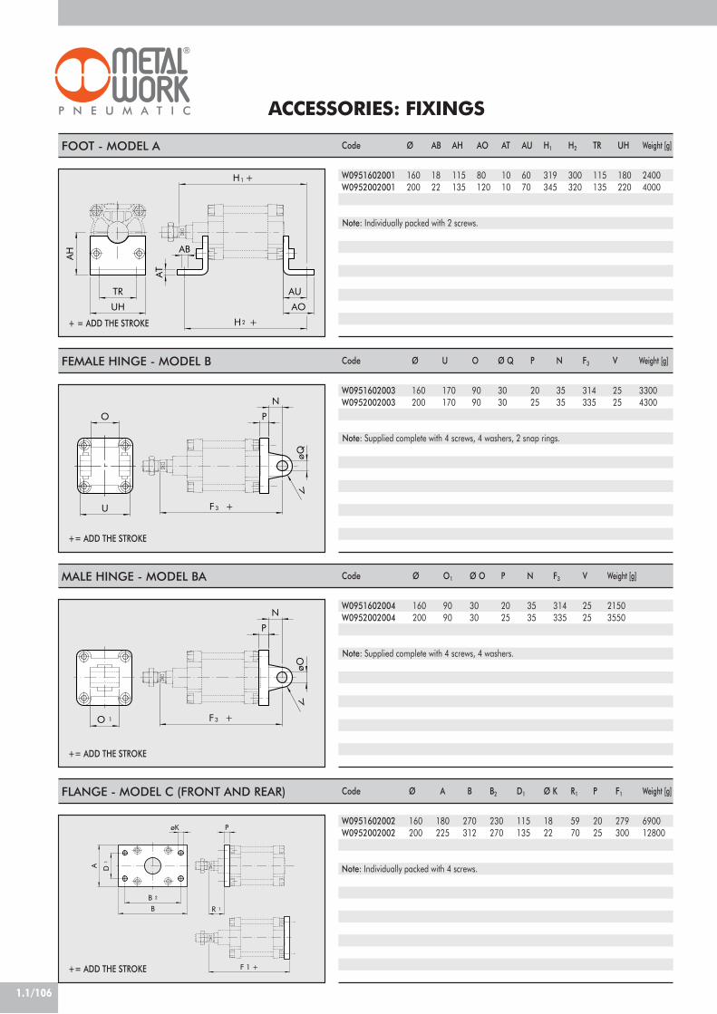
1.1/106
ACCESSORIES: FIXINGS
1
2
H +
AT
AB
AU
AO
AH
H +
TR
UH
V
3
O P
N
øQ
U F +
V
3O 1
P
N
øO
F +
FOOT - MODEL A Code
W0951602001W0952002001
FEMALE HINGE - MODEL B
+ = ADD THE STROKE
MALE HINGE - MODEL BA
+= ADD THE STROKE
Ø
160200
AB
1822
AH
115135
AO
80120
AT
1010
AU
6070
+= ADD THE STROKE
H1
319345
H2
300320
TR
115135
UH
180220
Code
W0951602003W0952002003
Ø
160200
U
170170
O
9090
Ø Q
3030
P
2025
N
3535
F3
314335
V
2525
Code
W0951602004W0952002004
Ø
160200
O1
9090
Ø O
3030
P
2025
N
3535
F3
314335
V
2525
Note: Supplied complete with 4 screws, 4 washers, 2 snap rings.
Weight [g]
24004000
Note: Individually packed with 2 screws.
Weight [g]
33004300
Note: Supplied complete with 4 screws, 4 washers.
Weight [g]
21503550
R 1
PøK
A
B 2
B
D1
F 1 +
Code
W0951602002W0952002002
Ø
160200
B2
230270
D1
115135
Ø K
1822
R1
5970
P
2025
F1
279300
Weight [g]
690012800
Note: Individually packed with 4 screws.
A
180225
B
270312
FLANGE - MODEL C (FRONT AND REAR)
+= ADD THE STROKE
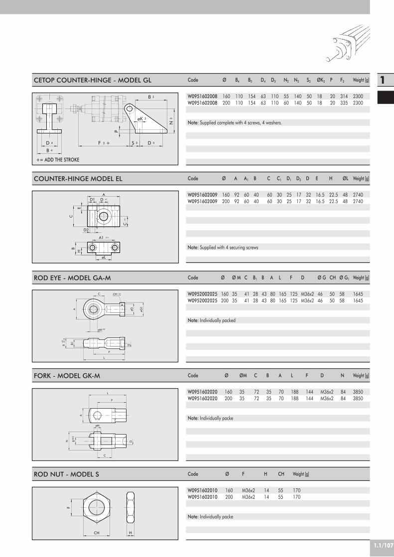
1.1/107
1
3D 4
B 4
F +
N3
D 5
P
B 5
øK 3
S 3
CETOP COUNTER-HINGE - MODEL GL
+= ADD THE STROKE
Code
W0951602008W0951602008
Ø
160200
B4
110110
B5
154154
D4
6363
D5
110110
N2
5560
N3
140140
S3
5050
ØK3
1818
P
2020
F3
314335
Weight [g]
23002300
Note: Supplied complete with 4 screws, 4 washers.
ROD EYE - MODEL GA-M
H7
CH
-0.1
2+
0
B1
F
L
D
C
A
øM
B
øG øG1
Code
W0952002025W0952002025
Ø
160200
Ø M
3535
C
4141
B1
2828
B
4343
A
8080
L
165165
F
125125
D
M36x2M36x2
Ø G
4646
CH
5050
Ø G1
5858
Weight [g]
16451645
Note: Individually packed
FORK - MODEL GK-M
B12
N
øM
F
L
B
A
C
D
Code
W0951602020W0951602020
Ø
160200
ØM
3535
C
7272
B
3535
A
7070
L
188188
F
144144
D
M36x2M36x2
N
8484
Weight [g]
38503850
Note: Individually packe
ROD NUT - MODEL S
H
F
CH
Code
W0951602010W0951602010
Ø
160200
F
M36x2M36x2
H
1414
CH
5555
Weight [g]
170170
Note: Individually packe
COUNTER-HINGE MODEL EL
A
HB
A1 ±0.2
øL
E
C
C±
0.1
D1 D H7
D2
Code
W0951602009W0951602009
Ø
160200
A
9292
A1
6060
B
4040
C
6060
C1
3030
D2
1717
D
3232
D1
2525
E
16.516.5
Note: Supplied with 4 securing screws
H
22.522.5
ØL
4848
Weight [g]
27402740

1.1/108
MAGNETIC SENSOR
SENSOR SUPPORT BRACKET FOR OLD VERSION BARREL(SHAPED)
9.1
11.5
25.534
17
CodeW0950000715
DescriptionBRACKET ACC. ST 160
52
7
18
M4
M6
16.5
49
26
46
M4
M6 45
42.5
26 4
4214
15.5
Code
W0950000201W0950000222W0950000232
Description
REED SENSOR ACC. DSM2-C525E.HALL PNP SENSOR ACC. DSM3-N225E.HALL NPN SENSOR ACC. DSM3-M225
CodeW0950000716
DescriptionBRACKET ACC. ST 200
Ø 160 Ø 200
SENSOR SUPPORT BRACKET FOR STANDARD VERSION(WITH ROUND BARREL) Code
0951602093
Description
BRACKET ACC. 160-200
9.5
M3
8
32 15
M5
41.5
33.5
40
RETRACTABLE SENSOR WITH INSERTION FROM ABOVE Description
HALL N.O. SENSOR, VERTICAL INSERTION 2.5mHALL N.O. SENSOR, VERTICAL INSERTION 300 mm M8REED N.O. SENSOR, VERTICAL INSERTION 2.5mREED N.O. SENSOR, VERTICAL INSERTION 300 mm M8HALL N.O. SENSOR, VERTICAL INSERTION 2m ATEX
Code
W0952025390W0952029394W0952022180W0952028184W0952125556
For technical data, refer to page 1.1/97
Hinweis: Technische Daten siehe Katalog sieite 1.1/93
ACCESSORIES: MAGNETIC SENSORS

1.1/109
1
NOTES
ADAPTOR FOR RETRACTABLE SENSOR
DescriptionAdaptor DSS005 for DST/ST brackets
CodeW0950001001
ASSEMBLY DIAGRAM
! ISO 15552 cylinder with traditional barrel" Sensor bracket mod. ST (Ø160 e 200)# Adaptor$ Retractable sensor with insertion from above% Retractable sensor
45
3
21

1.1/110
93 9116
10
154 5
62
87
12 13 14
11
TWIN RODS CYLINDERSERIES TWNC, Ø 32-100 mm
Anti-rotation cylinders with axial dimensions to ISO 15552.• Standard configuration with magnet• Double-acting – passing twinner rods and single passingrod• Polyurethane gasket
NBR - POLYURETHANEMax. 10 bar (max. 1 Mpa - 145 psi)
–10°C to +80°CFiltered, unlubricated air. Lubrication, if used, must be continuous.
Ø 32; Ø 40; Ø 50; Ø 63; Ø 80, Ø 100;25 to 500 mm
! Maximum recommended strokes. Higher values can create operating problemsExtruded profile
Magnetic standard cushionedØ 32: 434N / 350N Ø 40: 678N / 597N
Ø 50: 1060N / 940N Ø 63: 1683N / 1471NØ 80: 2714N / 2295N Ø 100: 4241N / 3812N
See GENERAL TECHNICAL DATA PAGE 1.1/06
TECHNICAL DATAGasketsOperating pressureTemperature range °CFluidBores mmStrokes ! mm
DesignEsecutionForces generated at 6 bar thrust/retraction N
Weight
COMPONENTS
! PISTON ROD: thick chromed steel" HEAD: aluminium alloy# PISTON ROD GASKET: polyurethane$ GUIDE BUSHING: sintered bronze% BARREL: drawn anodised aluminium alloy& PISTON: aluminium alloy' PISTON GASKET: polyurethane( MAGNET: plastoferrite) BUFFER+STATIC O-rings: NBR* CUSHIONING GASKET: NBR or polyurethane+ NEEDLE: OT 58 brass, SCREWS: Tap Tite for fixing and assembly- GUIDE RING: special technopolymer. REAR CUSHIONING CONE: OT58 brass/ FRONT CUSHIONING CONE: aluminium0 FLANGE: zinc-plated steel

1.1/111
1
W142
CH1 CH2
RT CH3
h9
G2A1
G3
P2
U
E
PL1
VDN
C
A
P1Q1
EBG
E
TG
TG
P
F
Q
S
V
O
D
WH+
EE
L0+
B
C1
PL
I
E
KKK
RT CH3h9
W140
A1
A
G3
P2
C
UPL1
G2
E
VA
B
P1Q1
V
P
Q
S
O
EE
PL
IK EE
TG
TG
E
N
L0+
BG
TWIN RODS CYLINDER
SINGLE THROUGH-ROD CYLINDER
+ = ADD THE STROKE
+ = ADD THE STROKE
Ø3240506380100
PL101214161820
PL1131214161820
A101010101212
A110.51010101212
B303540454555
CH1101317172222
CH2171924243030
CH3 6 6 8 81010
TG32.53846.556.57289
RTM6M6M8M8M10M10
L0100100106116131138
BG14.514.517.517.521.521.5
N4.54.55.55.55.55.5
P1 8 6 6 61010
P2192230385070
Q446677
Q1-46677
C151518222525
C1162025253338
F222432324040
I182230384860
K h9 32 40 50 63 80100
V404043475050
P 6 6 6 61010
EEG1/8G1/4G1/4G3/8G3/8G1/2
E 46 54 64.5 75.5 94111
D121620202525
KKM10x1.25M12x1.25M16x1.5M16x1.5M20x1.5M20x1.5
S101012162222
O445555
VD 6.5 813141214
U 45 49 54 69 89109
G2M6M8M8M10M12M12
G3 - -M8M10M12M12
WH263037374651
Ø3240506380100
PL101214161820
PL1131214161820
A101010101212
A110.51010101212
B303540454555
CH3 6 6 8 81010
TG32.53846.556.57289
VA444444
EEG1/8G1/4G1/4G3/8G3/8G1/2
RTM6M6M8M8M10M10
E 46 54 64.5 75.5 94111
L0100100106116131138
BG14.514.517.517.521.521.5
P 6 6 6 61010
P1 8 6 6 61010
P2192230385070
Q446677
Q1-46677
C151518222525
I182230384860
K h93240506380100
S101012162222
O445555
N4.54.55.55.55.55.5
V404043475050
U 45 49 54 69 89109
G2M6M8M8M10M12M12
G3 - -M8M10M12M12
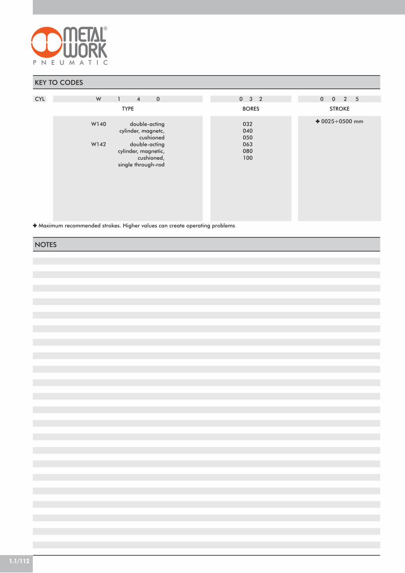
1.1/112
W 1 4 0
W140 double-actingcylinder, magnetc,
cushionedW142 double-acting
cylinder, magnetic,cushioned,
single through-rod
0 3 2
032040050063080100
0 0 2 5
! 0025÷0500 mm
TYPE BORES STROKE
KEY TO CODES
CYL
! Maximum recommended strokes. Higher values can create operating problems
NOTES

1.1/113
1
1
2
TR
UH
AH
AO
AU
H +
H +
øAB
AT
HH
E
HH
F
3
L
G
H +
D
HH
E
HH
F
3
GD
H +
ACCESSORIES: FIXINGS
FOOT - MODEL A/S
FEMALE HINGE - MODEL B
+ = ADD THE STROKE
MALE HINGE - MODEL BA
+= ADD THE STROKE
Ø
3240506380100
+= ADD THE STROKE
Code
W0950323001W0950403001W0950503001W0950633001W0950803001W0951003001
AB
79991214
AH
323645506371
AO
354347476166
AT
444666
AU
242832324141
TR
323645506375
UH
4552657595115
H1
164168181195222229
H2
148156170180213220
Ø
3240506380100
Code
W0950322003W0950402003W0950502003W0950632003W0950802003W0951002003
D
262832405060
E
222527323641
F
111313171721
G
101212161620
H
101012121616
H3
162165176195217229
L
4552607090110
Ø
3240506380100
Code
W0950322004W0950402004W0950502004W0950632004W0950802004W0951002004
D
262832405060
E
222527323641
F
111313171721
G
101212161620
H
101012121616
H3
162165176195217229
Note: Supplied with 4 screws, 4 washers, 2 snap-rings and 1 pin.
Weight [g]
7698156246406540
Weight [g]
1161602523946701085
Note: Individually packed with 2 screws.
Weight [g]
94124220316578850
Note: Supplied with 4 screws, 4 washers.
For fixing the leg to the supporting surface, it is advisable to use a DIN 7984 sunk-headed screw.

1.1/114
B E
H
F
3
M
H +
BB1
B 4 B 3
B 2 L +
D 4
V 1 B 3
D 4
B 2
B 4
B1B
ARTICULATED MALE HINGE - MODEL BAS
REAR FLANGE - MODEL C
+ = ADD THE STROKE
FRONT FLANGE - MODEL C
+= ADD THE STROKE
Ø
3240506380100
Code
W0950322006W0950402006W0950502006W0950632006W0950802006W0951002006
E
222527323641
F
161919242430
H
101012121616
H3
162165176195217229
M
101212161620
N
141616212125
Ø
3240506380100
Code
W0950322002W0950402002W0950502002W0950632002W0950802002W0951002002
B
647290100126150
B2
5055657595115
B3
101012121616
B4
323645506375
D4
79991214
L
140140149163181188
Code
W0950323002W0950403002W0950503002W0950633002W0950803002W0951003002
B1
8090110120153178
Ø
3240506380100
B
647290100126150
B2
5055657595115
B3
101012121616
B4
323645506375
D4
79991214
V1
303031353434
B1
8090110120153178
Note: Supplied with 4 screws.
Weight [g]
106142236336572840
Note: Supplied with 4 screws, 4 washers.
Note: Supplied with 4 screws.
Weight [g]
24629052267014202040
Weight [g]
22828848656911451760

A
HB
A1 ±0.2
øL
E
C
C±
0.1
D1 D H7
D2
1.1/115
1
8
7
(max)
N 4
N2
N 3
N1
N2
N 5A 6 (min)
A + 1/2
A +
+ = ADD THE STROKE+1/2 = ADD HALF THE STROKE
I
LF
C
A
E
G
N
B
M
H
D
Ø
3240506380100
Code
095032200709504020070950502007095063200709508020070951002007
N1
50637590110132
N2
121616202025
N3
121616202025
N4
222832354045
N5
657595105130145
A6
798291.595.5108110.5
Ø
3240506380100
Code
W0950322009W0950402009W0950402009W0950632009W0950632009W0951002009
A
465555656575
B
182121232328.5
C
303636404050
C1
151818202025
D1
111515181820
D2
799111113
Code
W0950322008W0950402008W0950502008W0950632008W0950802008W0951002008
A1
323636424250
Ø
3240506380100
A
262832405060
C
799111114
D
101212161620
E
253232404050
F
203232505070
G
324545636390
B
192626333344
A7
919097.5104.5115.5119
A8
10398103.5113.5123127.5
D
121616202025
E
6.5 8.5 8.510.510.512.5
H
3754547575103
I
415252636380
L
182525323240
M
81010121216
N
101212151522
Note: Supplied with 4 screws.
Note: Supplied with 4 screws, 4 washers.
H
10.51212131316
Note: Supplied with 4 screws, 2 pin.
Weight [g]
282582880123020302600
Weight [g]
162278278414414715
Weight [g]
96216212440464985
INTERMEDIATE HINGE - MODEL EN
COUNTER-HINGE FOR MODEL EN - MODEL EL
COUNTER-HINGE CETOP FOR MODEL BMODEL GL
ØL
222828353540

1.1/116
J
B GCD
M
N
C
D
E
L
Ø
3240506380100
B
25.527.531.539.549.559.5
C
32.53846.556.57289
D
4552657595115
E
77991111
G
323645506373
J
111313171721
L
101012121620
M
101212161620
Code
W0950322108W0950402108W0950502108W0950632108W0950802108W0951002108
N
101212151522
Note: Supplied with 4 screws, 4 washers.
Weight [g]
106138252350655980
COUNTER-HINGE ISO FOR MODEL B-MODEL GS
ACCESSORIES: MAGNETIC SENSORS
9.1
11.5
25.534
17
ORDERING CODESCodeW0950000201W0950000222W0950000232
NB: For technical features of sensors see page 1.1/93
DescriptionREED SENSOR ACC. DSM2-C525 HSE.HALL PNP SENSOR ACC. DSM3-N225E.HALL NPN SENSOR ACC. DSM3-M225
13.2
2.7
18.5
M5
5.9
19.2
14
29.5
SENSOR BRACKET
Code DescriptionW0950000711 BRACKET ACC. D.32-40 DST 80
Code DescriptionW0950000712 BRACKET ACC. D.50-63 DST 81
Code DescriptionW0950000713 BRACKET ACC. D.80-125 DST 82
Ø 32÷40 Ø 50÷63 Ø 80÷100
29.8
14.8 1.8
20.9
14
M5
20.4
1.6
26
20.6
1.7
7.5
25.9
47.8
M5
14

1.1/117
1
RODLESS CYLINDERØ 16, 25, 32, 40, 63
Rodless cylinders come in five different bores - Ø 16, 25,32, 40 and 63 mm – and the design incorporates numerousinnovations.• Calibrated extruded anodized aluminium alloy jacket.• Sensor slots and accessory slots in the jacket itself.• Longitudinal seal by means of specially-shapedindeformable stainless steel strips.• Strokes 100 to 5700 mm with 1mm intervals.• Adjustable integrated pneumatic cushioning• Adjustable limit switches and decelerations can be appliedat any time.• For this type of cylinder (size 32 and upwards), the valvescan be fitted directly using the retracting sensors withoutrequiring any intermediate brackets.Refer to the table on page 1.1/97.
TECHNICAL DATA
COMPONENTS
! CYLINDER HEAD: aluminium alloy" BARREL: profiled anodized aluminium
alloy# PISTON GASKET: NBR or FKM/FPM$ CENTRAL ELEMENT: aluminium alloy% SCRAPER: Hostaform®
& O-RING: FKM/FPM' PISTON: Hostaform®
( CUSHIONING CONE: aluminium alloy) STATIC O-RINGS: NBR or FKM/FPM* SLIDE: aluminium alloy+ OUTER STRIP: stainless steel, INNER STRIP: stainless steel- BAND SUPPORT: Hostaform®
NBR FKM/FPM
1 ÷ 80.1 ÷ 0.8
14.5 ÷ 116–15 ÷ 80- 5 ÷ 176
50 m unlubricated filtered air Lubrication, if used, must be continuous.Ø 16, 25, 32, 40 and 63
Double-acting rodless cylinder with direct transmission systemfor Ø 16 :100 to 5000 mm with 1mm interval
for Ø 25, 32 and 40 :100 to 5700 mm with 1mm intervalfor Ø 63 :100 to 5500 mm with 1mm interval
V<1 m/s (NBR) V>1 m/s (FKM/FPM)< 1 m/s (NBR) 2 m/s (FKM/FPM)
See GENERAL TECHNICAL DATA PAGE 1.1/07
For versions no-stick slip, use no-lubricated air only
Operating pressure barMPa
psiTemperature range °C
°FFluidBores mmType of constructionStrokes
Recommended speedsMax. speed with deceleratorsWeight
3 9813 6 71251 2 11 104

1.1/118
DIAGRAM OF SPEED AND MAXIMUM CUSHIONABLE LOAD
DIMENSIONNG - FORCE AND TORQUEBore
Ø1625324063
Centre DistanceY9
14182244
Actual ForceF at 6 bar [N]
110250420640
1550
Cushioning stroke[mm]1521263240
Max. loadL [N]120300450750
1650
Mv max[Nm]0.5348
24
Mamax [Nm]
4153060
200
Mrmax [Nm]
0.31248
NB: When the cylinder is subjected simultaneously to torque and force, it is advisable to keep to the following equations.Ma = F x ha Mr = L x hv + G x hr Mv = F x hv
MvMv max
! 1;LL max
! 1;MaMa max
+MrMr max
+ 0.22 xMvMv max
+ 0.4LL max
! 1
For the cylinder to reach the end-of-strokeposition without intense or repeated impactwhich would damage it, it is necessary toannul the kinetic energy of the moving massand the work generated. The maximumcushionable load depends on the traversingspeed and the absorption of the air buffersupplied standard with the various cylinders.The diagram shows the speeds andcushionable mass for the various diametersat a pressure of 6 bar.
F
LG
Ma Mr
MVha
y
hv
hr
1000 2000500
3000 4000
ø25
ø32
35002500100 1500
ø16
ø40
ø63
1000
100
1500
0.1
500
2000
10
MAXIMUM LOAD ACCORDING TO THE DISTANCE BETWEEN SUPPORTS
L
L
K K
K
Diagram of maximum loadLoad L (N)
Distance K (mm)
ø16ø32ø25
ø40
Diagramma di ammortizzamento
Velocitàpistone[m/sec]
0.1
Massa da ammortizzare [Kg]
0.2 52 3 41 10010 10000.5 20 50 200 500
10
5
2
1
0.1
0.2
0.5
ø63
Cushioning diagram
Mass to be buffered (kg)
Pistonrate
(m/sec.)

1.1/119
1
DIMENSIONS OF RODLESS CYLINDER Ø 16÷40
G
270
G G
N
M1
M2
T
R
W
Z3
WS
VS
W V
S
UP
W1W
2Z2
Z1
Z3
Z4
O J
H
MFE
CBD
K
Y
N1
A +
BARREL CROSS SECTION
ø16 ø25 ø32 ø40 ø63
18.6
63.653
1
22.2
605
12.810
3850
36
362
241.
5
24 100
100
3824
0.5 12
+ = ADDED STROKE
Ø16253240
A130200250300
B12172345
C15232730
D76120150150
E64100110110
F48809090
GM51/81/41/4
H1218.52224
J6.48.510.515
K32505555
MM4M5M6M6
M1M3M5M6M6
N7121417.5
N18111212
O6131212
P43.5668697
R23.529.63636.8
S18232728
T2.753.34.44.4
U10151818
V18274054
VS18273654
W27405669
WS27405272
W113.5203036
W2913.52227
Y4.56.589
Z137.5537485
Z224334449
Z34.56.5811.8
Z428427070
M2M5M6M8M8

1.1/120
ø63
ø32; ø40ø16; ø25
271
H
E
C
AG
D
EF
øB
L
H
C
G
L
A
D
C
E
H
AL
DøB F
F
øB
RODLESS CYLINDER WITH SWING CARRIAGE
NOTE: For other dimensions see code 270
DIMENSIONS OF RODLESS CYLINDER Ø 63
G3/8
A
M8 depth 17N° 4 x M8 depth 9
G3/8
FB
C
D
E
G
H
A
FB
E
CG
D
H
G3/8
15N° 8 x M8 12
140
180
218
257 47 39
32
14.5
103
34
50
59.5
120
103
78
78
430 +
11.5
48
9.2
Basic supplyA, B, C, D to feed to left chambersE, F, G, H to feed the right chambersNote: B, C, D, F, G and H are supplied closed with threaded plugs.
If you modify the position of an inner plug following the instructions provided with the cylinder, you can arrange:
all feeds from the left all feeds from the rightA, B feed the left chambers E, F feed the right chambers
C, D feed the right chambers G, H feed the left chambers + = ADDED STROKE
Ø1625324063
A2537707080
ØB4.55.56.56.5M8
C1320383832
D23558
E2030909080
F1016757565
G––555537
H47-5072-7591-100111-120155-162
L2842707082

1.1/121
1
273
ø63
ø16 ø25÷ø40
B max G
W7
W8
Z5Y1
Z4 WS4
Y1
Z5
W8
WS4
C1
W7
D
Z4
B max
D
W8W
7
C1
D
C1
E
WS4
Z5Z4
B max
DIMENSIONS OF RODLESS CYLINDER + ADJUSTABLE LIMIT SWITCH AND SHOCK ABSORBERS
KEY TO CODES
CYL 2 7
27 Rodlesscylinder
0
0 Standard1 With swing drive
!2 Twin cushionedseries “Double”
3 Double-acting cushionedMagnetic + adjustable limit
switchesand shock absorbers
2 5
1625324063
C N
TYPE STROKE
0 0 5 00
0 magneticS non-
magnetic"G No stick
slip
CONFIGURATIONBORE
Ø 16:from 100 to 5000mmØ 25÷40:from 100 to 5700 mmØ63from 100 to 5500 mm
C N NBR#V FKM/FPM
Ø
1625324063
B Max
427290105105
C1
2244567465
D
M12x1M14x1.5M20x1.5M25x1.5M36x1.5
W7
38537489128.5
W8
466789108153
WS4
42506075103
Y1
7.5541.5–
Z4
781012.516
Z5
7.59.812.212.719
Stroke
1016222525
Max. cushioned forcefor stroke [J]
4.5184065
125
for hour [J]1412534000537007000091000
Max. impactforce [N]
1000280037505500
11120
Max. thrustforce [N]
220530890
15502220
E
–172932.8–
G
–91114–
" For speed ! 0.2 m/s # For speed " 1m/s ! Available up to Ø 32
For graphs to help choose shock absorbers see page 1.1/124

1.1/122
ACCESSORIES
FOOT Ø 16; 25
ø AB
UH
TR AO
H +A
T
AU
AH
FOOT Ø 32; 40
TR AO
H +
AT
UH
ø AB
AV AUAH
Code
W0950167001W0950257001
Ø
1625
ØAB
3.65.5
AH
1.52
AO
1422
AT
1.62.5
AU
46
TR
1827
UH
2640
H
150232
Code
W0950327001W0950407001
Ø
3240
ØAB
6.69
AH
42
AO
2525
AT
2020
AU
811.5
TR
3654
UH
5171
H
284327
AV
2030
Weight [g]
1032
Note: Individually packed with 2 screws.
Note: Individually packed with 2 screws.
Weight [g]
88112
FOOT Ø 63
UH
TR
ø AB
AT
AUAO
H +
Code
W0950637001
Ø
63
ØAB
11
AT
7
AO
64
TR
78
UH
103
H
460
Note: Individually packed with 2 screws.
Weight [g]
360
+ = ADDED STROKE
INTERMEDIATE FOOT Ø 32; 40
øAB
AHTR
AT
AV
AOUH
Ø
3240
ØAB
6.56.5
AH
57
AO
5560
AT
88
TR
61.570÷75
UH
7385
AV
4045
Note: plate supplied complete with 4 screws, 4 fixing plates
Weight [g]
72104
Code
W0950327032W0950407032
INTERMEDIATE FOOT Ø 63
øAB
AT
AO
UH
TR
INTERMEDIATE FOOT Ø 16; 25
øAB
UH
AT
TR AO AH
Code
W0950167031W0950257031
Ø
1625
ØAB
5.55.5
AH
34
AO
2020
AT
56
TR
4148
UH
5360
Weight [g]
46
Note: Individually packed.
Ø
63
ØAB
8.5
AH
7.5
AO
55
AT
7.5
TR
78
UH
103
Note: plate supplied complete with 4 screws, 4 fixing plates
Weight [g]
330
Code
W0950637032
+ = ADDED STROKE
+ = ADDED STROKE
AU
15

1.1/123
1
DRIVE PIN
A
B øC
Code
W0950167034W0950257034W0950327034W0950327034W0950637034
Ø
1625324063
A
2.958810
B
2842707082
ØC
58121214
Weight [g]
6165252100
Note: Individually packed.
KIT TO TRANSFORM INTO SWING VERSION Code
W0950167035W0950257035W0950327035W0950327035W0950637035
Ø
1625324063
Weight [g]
34118450450810
Ø16÷40 Ø63
Note: Supplied with 1 stud pin, 2 screws
SLIM SENSOR
SENSOR SUPPORT Ø 16; 25
For technical data, refer to page 1.1/98
Code
W0952025390W0952029394W0952022180W0952028184W0952125556
Description
HALL N.O. SENSOR, VERTICAL INSERTION 2.5mHALL N.O. SENSOR, VERTICAL INSERTION 300 mm M8REED N.O. SENSOR, VERTICAL INSERTION 2.5mREED N.O. SENSOR, VERTICAL INSERTION 300 mm M8HALL N.O. SENSOR, VERTICAL INSERTION 2m ATEX
Code
0950164001
Description
SENSOR SUPPORT STD
SWING SUPPORT Ø 32; 40; 63
A
C
D
E
øB
FG
Code
W0950327033W0950327033W0950637033
Ø
324063
A
707080
ØB
6.56.5M8
C
383832
D
558
E
909080
F
757565
G
555537
Weight [g]
274274400
Note: Individually packed.
SWING SUPPORT Ø 16; 25
A
øB
D
E
F
C
Code
W0950167033W0950257033
Ø
1625
A
2537
ØB
4.55.5
C
1320
D
23
E
2030
F
1016
Note: Individually packed.
Weight [g]
1440
Note: ø16÷40: Supplied complete with 1 adaptor, 1 support, 1 pin, 1 bushingø63: Supplied complete with 1 plate, 1 support, 1 pin, 2 bushings, 4 screws

5.8 500
4.9
1.1/124
ADJUSTABLE LIMIT SWITCH ANDSHOCK ABSORBERS KIT Description
ACC. RODLESS CYLINDER LIMIT SWITCH AND SHOCK ABSORBERS Ø 16ACC. RODLESS CYLINDER LIMIT SWITCH AND SHOCK ABSORBERS Ø 25ACC. RODLESS CYLINDER LIMIT SWITCH AND SHOCK ABSORBERS Ø 32ACC. RODLESS CYLINDER LIMIT SWITCH AND SHOCK ABSORBERS Ø 40ACC. RODLESS CYLINDER LIMIT SWITCH AND SHOCK ABSORBERS Ø 63
Code
09501640020950254002095032400209504040020950634002
Weight [g]
1252604607301620
Note: Supplied complete with 1 shock absorber support, 1 standard shock absorber , 1 shockabsorber nut, 1 limit switch grub screw, 1 grub screw nut ( 2 for ø63) , 1 bracket, 1 bracket screw,4 locking grub screws (for Ø 16 and Ø 25), 4 locking plates and 4 screws (for Ø 32 and Ø 40).
GRAPHS TO HELP CHOOSE THE RIGHT SHOCK ABSORBERS
The dotted areas indicate that the SHOCKABSORBERS is supplied standard.Other options can be selected dependingon the speed [m/sec] and the maximumwork force [J/stroke] to dissipate at eachstrokeRefer to the diagrams above to select thecorrect option.
1.5
1
m/s
ec
0.5
0
-1
J/stroke1 2 3 4 5
-2
-3
2
standard
J/stroke
-1
-3
-2
4 8 12 16 20 24 28 32 36 400
0.5
1.5
1
2
standard
m/s
ec
J/stroke
standard
-1
-3
-2
2 6 1210 18 2084 14 160
0.5
1
1.5
2
m/s
ec
J/stroke
standard
-1
-3
-2
0
1.5
1
0.5
2
m/s
ec
10 5020 7040 6030 12010040J/stroke
m/s
ec
standard
-2
-3
-1
20 60 800
2
1
3
4
SLOTTED FIXING PLATE Description
ACC. M3 T-SLOTTED FIXING PLATEACC. M4 T-SLOTTED FIXING PLATE
Code
09500030010950003002
Note: Individually packed
Weight [g]
11
ø16 ø25 ø32
ø40 ø63
BAR FOR GROOVING
Note: the code corresponds to 1 piece
Code
W0950000160
Description
BAR FOR GROOVING L=500 mm
Ø16 Ø63Ø25÷40
SHOCK ABSORBERS Description
Shock absorbers PR015 MF1 + nut M12x1.5Shock absorbers PR025 MC2 + nut M14x1.5Shock absorbers PR050 MC2 + nut M20x1.5Shock absorbers PR0100 MF2 + nut M25x1.5Shock absorbers PR0125 MF3 + nut M36x1.5
Code
09500040030950004004095000400509500040060950004007
Bore
ø16ø25ø32ø40ø63

ø2x25 ø2x32
Diagramma di ammortizzamento
Velocitàpistone[m/sec]
0.1
Massa da ammortizzare [Kg]
0.2 52 3 41 10010 10000.5 20 50 200 500
10
5
2
1
0.1
0.2
0.5
ø2x16
1.1/125
1
DIMENSIONS OF RODLESS CYLINDER, DOUBLE SERIES
272
GG
T
R
N1
A +M
1
HE
F JVS
D
NVW
WW
K
O
P
CB
WS
T
Y
U
M
Z
S
Ø2x162x252x32
A130200250
B121723
C152327
D76120150
E64100110
F488090
GM51/81/4
H1218.522.5
J6.48.510.5
K325055
MM5M6M6
N101512
M1M3M5M6
N171214
O162020
P53.57495
R486686.5
S425977.5
T33.54.5
U345070
VW426386
VS182740
WW5172100
WS274156
Y4.578
Z37.553.574
DIAGRAM OF SPEED AND MAXIMUM CUSHIONABLE LOAD
DIMENSIONS – FORCES AND MOMENTSBore
Ø2x162x252x32
Actual forceF at 6 bar [N]
200480820
Cushioning stroke[mm]152126
Max loadL [N]240600900
Mvmax [Nm]
16
10
Ma = F x ha Mr = L x hv + G x hr MV = F x hv
(For the weights see GENERAL TECHNICAL DATA PAGE 1.1/07)MV
F
LG
Ma Mr
hv
y
ha
hr
Mamax. [Nm]
83060
Mrmax. [Nm]
2.48
16.5
For the cylinder to reach the end-of-strokeposition without intense or repeated impactwhich would damage it, it is necessary toannul the kinetic energy of the moving massand the work generated. The maximumcushionable load depends on the traversingspeed and the absorption of the air buffersupplied standard with the various cylinders.The diagram shows the speeds andcushionable mass for the various diametersat a pressure of 6 bar.
+ = ADD THE STROKE
RODLESS CYLINDERDOUBLE SERIES Ø 16, 25, 32
MvMv max
! 1;LL max
! 1;MaMa max
+MrMr max
+ 0.22 xMvMv max
+ 0.4LL max
! 1
Cushioning diagram
Pistonrate
(m/sec.)
Mass to be buffered (kg)
NB: When the cylinder is subjected simultaneously to torque and force, it is advisable to keep to the following equations.
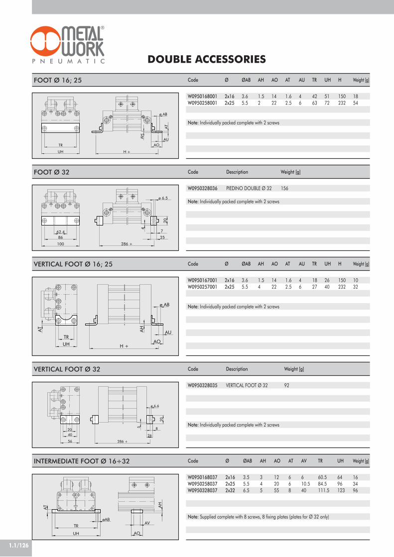
DOUBLE ACCESSORIES
1.1/126
62.4
286 +
4
20
86
100
ø 6.5
7
25
TR
UH
AO
H +
AT
AUAH
ø AB
Ø
2x162x25
Code
W0950328036
Description
PIEDINO DOUBLE Ø 32
UH
AT
TR
ø AB
AH
AOH +
AU
Code
W0950167001W0950257001
56
40
286 +
26
8
20
ø 6.6
20
5
Code
W0950328035
Description
VERTICAL FOOT Ø 32
AT
TR
UH
øAB
AO
AV
AH
ØAB
3.65.5
AH
1.52
AO
1422
AT
1.62.5
AU
46
TR
4263
UH
5172
H
150232
Ø
2x162x25
ØAB
3.65.5
AH
1.54
AO
1422
AT
1.62.5
AU
46
TR
1827
UH
2640
H
150232
Code
W0950168001W0950258001
Code
W0950168037W0950258037W0950328037
Ø
2x162x252x32
ØAB
3.55.56.5
AH
345
AO
122055
AT
668
AV
610.540
TR
60.584.5111.5
UH
6496123
Weight [g]
1854
Note: Individually packed complete with 2 screws
Note: Individually packed complete with 2 screws
Weight [g]
156
Weight [g]
1032
Note: Individually packed complete with 2 screws
Weight [g]
92
Weight [g]
163496
Note: Individually packed complete with 2 screws
Note: Supplied complete with 8 screws, 8 fixing plates (plates for Ø 32 only)
FOOT Ø 16; 25
FOOT Ø 32
VERTICAL FOOT Ø 16; 25
VERTICAL FOOT Ø 32
INTERMEDIATE FOOT Ø 16÷32

1.1/127
1
RODLESS CYLINDER WITH BALLRECIRCULATING GUIDE Ø 16, 25, 32, 40, 63
The range of rodless cylinders with ball circulation guides is availablewith five different bores Ø 16, 25, 32,40 and 63.The bore 63 can be supplied in two versions: the "standard" one forintermediate loads and the "heavy" one for considerably weighty loads.Besides the general features specified for standard rodless cylinders, theother main features are:• Very high load capacity, acting in all directions without dischargingonto the cylinder slide.• Hardened steel guide connected firmly to the cylinder jacket.• Ball circulation shoes constructed using special technology that makethem very silent when the guide slides, with very long maintenanceintervals. For example, they only need lubricating every 2000 km oronce a year.• Extra sturdy slide support with various holes for fixing the loads. Holesfor centring pins are also provided.• 100 to 2650 stroke at intervals of 1 mm.• Integrated pneumatic adjustable cushioning.• Adjustable limit switches and decelerations can be applied at any time.For this type of cylinder (size 32 and upwards), the valves can be fitteddirectly using the retracting sensors without requiring any intermediatebrackets.Refer to the table on page 1.1/97.
TECHNICAL DATA
COMPONENTS
For version 275! CYLINDER: see construction details onpage 1.1/117" GUIDE: hardened steel# SHOE: steel with hardened ballcirculation$ SLIDE SUPPORT: anodised aluminium
For version 276Besides the details specified above:% END-OF-STROKE STUD PIN: zinc-platedsteel, complete with 2 zinc-plated nuts forfixing.& DECELERATOR: burnished steel,complete with 2 zinc-plated or burnishednuts for fixing' DECELERATOR SUPPORT: anodisedaluminium( BRACKET: hardened-and-tempered andzinc-plated steel
2 3 4
5 6 7
8
1
Operating pressure barMPa
psiTemperature range °C
°FFluidBoresType of constructionStrokes
Threaded portsAssemblyRecommended speedWeightMax. speed with decelerators
NBR FKM/FPM
0.5÷80.05÷0.8
7÷116–15÷80- 5÷176
50!m unlubricated filtered air lubrication, if used, must be continuousØ 16, 25, 32, 40 and 63
Doubl-acting rodless cylinder with direct transmission systemØ 16: 100 to 1350 with 1 mm intervalØ 25: 100 to 2300 with 1 mm intervalØ 32: 100 to 2300 with 1 mm intervalØ 40: 100 to 2250 with 1 mm interval
Ø 63 standard: 100 to 2100 with 1 mm intervalØ 63 heavy: 100 to 2650 with 1 mm interval
M5, G1/8”, G1/4”, G3/8”as required
<1 m/s (NBR) !1 m/s (FKM/FPM)See GENERAL TECHNICAL DATA PAGE 1.1/07
<1 m/s (NBR) 2 m/s (FKM/FPMs)For no-stick slip versions, use no-lubricated air only

1.1/128
3500
10000
1000
100
20001000
ø16
1500
0.1
500
3000
4000
2000
101500
ø40
ø32
ø25
6000
4000100 500
ø63 HEAVY
30002500
ø63 STANDARD
DIMENSIONES - FORCES AND MOMENTS
N.B.: when the cylinder is subjected simultaneously to torque and force, it is advisable to keep to thefollowing equationsMa = F x (hr + Y) Mr = G x (hr + z) + Lx (hv + X) Mv = F x (K + hv)
LG
K
hr
X hv
Z Y
MaMa max
+ ! 1Mr
Mr max+
MvMv max
+L
L max+
GG max
G
MV
Ma Mr
FL
DIAGRAM OF SPEED AND MAXIMUM CUSHIONABLE LOAD
For the cylinder to reach the end-of-strokeposition without intense or repeated impactwhich would damage it, it is necessary toannul the kinetic energy of the moving massand the work generated. The maximumcushionable load depends on the traversingspeed and the absorption of the air buffersupplied standard with the various cylinders.The diagram shows the speeds andcushionable mass for the various diametersat a pressure of 6 bar.
MAXIMUM LOAD ACCORDING TO THE DISTANCE BETWEEN SUPPORTS
L
L
K K
K
ø25 ø32ø16
ø40
0.1 0.2 52 3 41 10010 10000.5 20 50 200 500
2
1
0.1
0.2
0.5
ø63
Distance K (mm)
Diagram of maximum load
Load L(N)
Pistonrate
(m/sec.)
Mass to be buffered (kg)
Cushioning diagram
Ø
162532406363
Actual forceF at 6 bar [N]
110250420640
15501550
Max loadG [N]5001500300040006000
10000
Mv max[Nm]16100200200400600
Ma max.[Nm]16100200200400600
Mr max.[Nm]1550100140140400
Max loadL [N]500
1500300040006000
10000
Cushioningstroke [mm]
152126324040
K[mm]35
50.559688491
X[mm]1621
22.524.723.129.2
Y[mm]2944
53.5587979
Z[mm]33
51.57073
10088
Version
––––
standardheavy

1.1/129
1RODLESS CYLINDER WITH BALL RECIRCULATING GUIDE Ø 16
RODLESS CYLINDER WITH BALL RECIRCULATING GUIDE Ø 25
M5 M5
N°2 x ø4depth 7
H9
10
18
30
13.5
13.5
4.5
33
N°4
x M
4
48.5
18
9
60
842
22.5
7
5553.5
4.5
M4
48
76 12 15
130 +
27
27
8
37.5
43.5
6.4
12
7
M3
48
4
N°2 x ø5depth 8
H9
G1/8G1/8
5366
51.5
68.5
76.5N
°8 x
M5
6.5
20
274070.5
4027
9
515
67
13.5
38 24
80
11
M5
120 17
18.5
30 30 30 16
19
23
12
200 +
M5
8.5
6.5
+ = ADD THE STROKE
+ = ADD THE STROKE
Ø3240
RODLESS CYLINDER WITH BALL RECIRCULATING GUIDE Ø 32; Ø 40
H9
G1/4
N°2 x ø6depth 10
G1/4
A +B C150
J
H
Z3
WS1WSVS
10
M6W1
20
12
M690
N
40
W6
V
W2
P
YW
1
WZ1
N°8
x M
6
45 40
W3
W5
W4
6
18
35 35
A250300
B2345
C2730
H2224
J10.515
N1417.5
P8697
V4054
VS3654
W5669
WS5272
WS185104
W13036
W22227
W39598
W47073
W599102
W678.588
Y89
Z17485
Z3811.8
+ = ADD THE STROKE
275
275
275

1.1/130
RODLESS CYLINDER WITH BALL RECIRCULATING GUIDE Ø 63
A
D
H
F
G
B
C
E
N°2 x ø6depth 10
H9DG3/8C G3/8
N° 4 x M8depth 12
dept
h 9
G3/8
275
BG
H
AE
F
M8 depth 17
60
430 +
14.5
48
230 61 39
3447160
8040 32
78103
59.5
11.5
138.
5
N°2
x M
8 12
127
38.5N
°8 x
M6
54
29
135.5
78
103
15
G3/8 DN°2 x ø8depth 12
H9
M8 depth 17
C G3/8
dept
h 9
G3/8
BG
H
AE
F
275
N°4xM8depth 12
1270
78
430 +
59.5
103
103
15
65
130
260
292 30 39
32
14.5
50
34
138.
5
50.5
136
N°1
0 x
M8
36
14
48
7811
.5
142.5
N°2
x M
8
Basic supplyA, B, C, D to feed to left chambersE, F, G, H to feed the right chambersNote: B, C, D, F, G and H are supplied closed with threaded plugs.
If you modify the position of an inner plug following the instructions provided with the cylinder, you can arrange:all feeds from the left all feeds from the right
A, B feed the left chambers E, F feed the right chambers C, D feed the right chambers G, H feed the left chambers
HEAVY
STANDARD
Ø
1625324063
Interm. support code (1)W0950164004W0950254004W0950324004W0950404004W0950637032
Leg code (2)W0950167001W0950257001W0950328035W0950407001W0950637001
Amin8
1043–
Bmin1210115–
Interm. support code (1)W0950164004W0950254004W0950324004W0950404004W0950637036
Leg code (2))W0950167001W0950257001W0950327001W0950407001W0950637001
Horizontal layout Vertical layout
ASSEMBLY DIAGRAMS
2 12 3
2 11 2
1 212
2 1 21
275/276 (vertical)ø16÷40276 (horizontal)
ø16÷40275 (horizontal)ø16÷40
275/276 (horizontal)ø63
275/276 (verticall)ø63
A m
in
B m
in275
+ = ADD THE STROKE

1.1/131
1
Ø
162532406363
RODLESS CYLINDER WITH BALL RECIRCULATING GUIDE + SHOCK ABSORBERS Ø 16÷63
C1
ø63 HEAVY
ø16 ø25; ø32; ø40
276
ø63 STD
W8W
7
B maxZ5
Y1Z4
WS3
C1
WS4
D
Z4
Z5
WS2
WS4
D
Y1
B max
WS2
WS3
WS4Z5
B max
D
W7
W8
C1
Z4
WS4Z5
B max
D
W7
W8
C1
Z4
W8W
7
G
E
Bmax507290105105105
Max. cushioned forceC1
224456746565
D
M12x1M14x1M20x1.5M25x1.5M36x1.5M36x1.5
W7
38537489128.5128.5
W8
466789108153153
WS2
527182.592––
WS3
5680.591108––
WS4
42506075103103
Y1
7.5541.5––
Z4
781012.51616
Z5
7.59.812.212.71919
Stroke
101622252525
Per stroke [J]4.5184065
125125
Per hour [J]141253400053700700009100091000
Max. impactforce [N]
1000280037505500
1112011120
Max. thrustforce [N]
220530890
155022202220
For graphs to help choose shock absorbers see page 1.1/124
KEY TO CODES
Version
––––standardheavy
E
–172932.8––
G
–91114––
CIL 2 7
27 Rodlesscylinder
5
5 Double-acting cushionedmagnetic with ball circulation guides6 Double-acting cushionedmagnetic with ball circulation guides
+ adjustable limit switchand shock absorbers
2 5
1625324063
C NTYPE STROKE
0 0 5 00
0 STD Magnetic S STD Non magn.!G STD No stick slip
A HEAVY Magnetic! B HEAVY No stick slip
C HEAVY Non magn.
CONFIGURATIONBOREØ 16: from 100 to 1350 mmØ 25-32: from 100 to 2300 mmØ 40: from 100 to 2250 mmØ 63 std: from 100 to 2100 mmØ 63 heavy: from 100 to 2650 mm
N NBR! V FKM/FPM
! For speed ! 0.2 m/s" For speed " 1 m/s
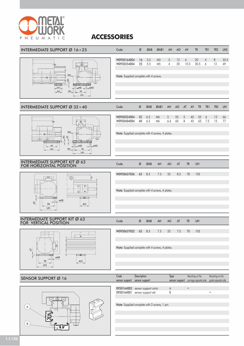
1.1/132
INTERMEDIATE SUPPORT Ø 16÷25
ACCESSORIES
UH
AV
AH
TRAO TR1
TR2
øAB øAB1
INTERMEDIATE SUPPORT Ø 32÷40
UH
TR1 TR
AH
AO
AV
AT
TR2
øAB øAB1
SENSOR SUPPORT Ø 16
A
B
Code
W0950164004W0950254004
Ø
1625
ØAB
3.55.5
ØAB1
M3M5
AH
34
AO
1220
AV
610.5
TR
2030.5
TR1
46
TR2
812
Typesensor support
AB
UH]
32.549
Note: Supplied complete with 4 screws.
Note: Supplied complete with 4 screws, 4 plates.
Note: Supplied complete with 2 screws, 1 pin.
Code
W0950324004W0950404004
Ø
3240
ØAB
6.56.5
ØAB1
M6M6
AH
56.6
AO
5560
AV
4045
TR
5563
TR1
67.5
TR2
1315
UH
6677
Mounting on thecarriage opposite side
•
Mounting on theguide opposite side
•
Codesensor support
09501640030950164001
Descriptionsensor support
sensor support cortosensor support std
AT
58
AOøAB
AT
UH
TR
Note: Supplied complete with 4 screws, 4 plates.
Code
W0950637036
Ø
63
ØAB
8.5
AH
7.5
AO
55
TR
78
UH
103
AT
8.5
AOøAB
UH
TR
AT Note: Supplied complete with 4 screws, 4 plates.
Code
W0950637032
Ø
63
ØAB
8.5
AH
7.5
AO
55
TR
78
UH
103
AT
7.5
INTERMEDIATE SUPPORT KIT Ø 63FOR HORIZONTAL POSITION
INTERMEDIATE SUPPORT KIT Ø 63FOR VERTICAL POSITION
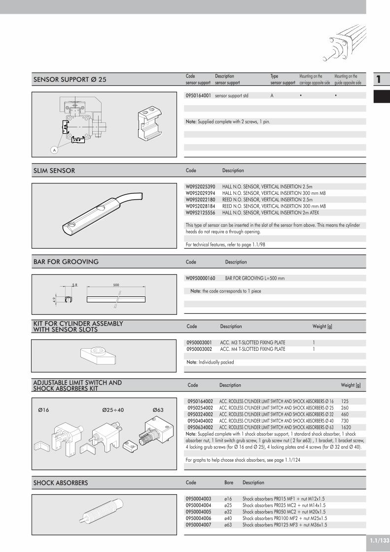
1.1/133
1
SLIM SENSOR Code
W0952025390W0952029394W0952022180W0952028184W0952125556
Description
HALL N.O. SENSOR, VERTICAL INSERTION 2.5mHALL N.O. SENSOR, VERTICAL INSERTION 300 mm M8REED N.O. SENSOR, VERTICAL INSERTION 2.5mREED N.O. SENSOR, VERTICAL INSERTION 300 mm M8HALL N.O. SENSOR, VERTICAL INSERTION 2m ATEX
This type of sensor can be inserted in the slot of the sensor from above. This means the cylinderheads do not require a through opening.
For technical features, refer to page 1.1/98
A
SENSOR SUPPORT Ø 25 Typesensor support
A
Note: Supplied complete with 2 screws, 1 pin.
Mounting on thecarriage opposite side
•
Mounting on theguide opposite side
•
Codesensor support
0950164001
Descriptionsensor support
sensor support std
ADJUSTABLE LIMIT SWITCH ANDSHOCK ABSORBERS KIT Description
ACC. RODLESS CYLINDER LIMIT SWITCH AND SHOCK ABSORBERS Ø 16ACC. RODLESS CYLINDER LIMIT SWITCH AND SHOCK ABSORBERS Ø 25ACC. RODLESS CYLINDER LIMIT SWITCH AND SHOCK ABSORBERS Ø 32ACC. RODLESS CYLINDER LIMIT SWITCH AND SHOCK ABSORBERS Ø 40ACC. RODLESS CYLINDER LIMIT SWITCH AND SHOCK ABSORBERS Ø 63
Code
09501640020950254002095032400209504040020950634002
Weight [g]
1252604607301620
Note: Supplied complete with 1 shock absorber support, 1 standard shock absorber, 1 shockabsorber nut, 1 limit switch grub screw, 1 grub screw nut ( 2 for ø63) , 1 bracket, 1 bracket screw,4 locking grub screws (for Ø 16 and Ø 25), 4 locking plates and 4 screws (for Ø 32 and Ø 40).
For graphs to help choose shock absorbers, see page 1.1/124
KIT FOR CYLINDER ASSEMBLYWITH SENSOR SLOTS Description
ACC. M3 T-SLOTTED FIXING PLATEACC. M4 T-SLOTTED FIXING PLATE
Code
09500030010950003002
Note: Individually packed
Weight [g]
11
5.8 500
4.9
BAR FOR GROOVING
Note: the code corresponds to 1 piece
Code
W0950000160
Description
BAR FOR GROOVING L=500 mm
Ø16 Ø63Ø25÷40
SHOCK ABSORBERS Description
Shock absorbers PR015 MF1 + nut M12x1.5Shock absorbers PR025 MC2 + nut M14x1.5Shock absorbers PR050 MC2 + nut M20x1.5Shock absorbers PR0100 MF2 + nut M25x1.5Shock absorbers PR0125 MF3 + nut M36x1.5
Code
09500040030950004004095000400509500040060950004007
Bore
ø16ø25ø32ø40ø63

1.1/134
SPARE PARTS
FKM/FPM GASKET KITposn. 3-4-5-6-7-10
Ø1625324063
CodeType 0 (0 rings)00901650150090255015009032501500904050150090635015
CodeType 1 (1 rings)00901650160090255016009032501600904050160090635016
CodeType 2 (2 rings)00901650170090255017009032501700904050170090635017
CodeType 3 (3 rings)00901650180090255018009032501800904050180090635018
CodeType A (4 rings)
–00902550190090325019
––
PISTON KIT POS 2 (X)
“LAST RELEASE” CYLINDER
BAN
DS
SUPP
ORTBlack
OrangeLight GreyDark Grey
White
Yellow
PIST
ON
Type A
Type 0
Type 1
Type 2
Type 3
X Y
Spare parts labelon one cylinder side
! Bands support Kit" Piston kit# $ % & ' ( NBR gaskets Kit (FKM/FPM for ')# $ % & ' ( FKM/FPM gaskets Kit) * Bands Kit (inner/outer)
7
8
6
19
10
26 7103 45 89 1
XY
BANDS SUPPORT KIT POS 1 (Y)
Ø1625324063
CodeWhite
0090165080009025508000903250800090405080
*0090635080
CodeBlack
0090165081009025508100903250810090405081
*0090635081
CodeOrange
0090165082009025508200903250820090405082
*0090635082
CodeLight grey
0090165083009025508300903250830090405083
*0090635083
BANDS KIT (inner and outer)pos 8-9Ø
1625324063
Code
0090166…0090256…0090326…0090406…0090636…
CodeDark grey
0090165084009025508400903250840090405084
*0090635084
CodeYellow
0090165085009025508500903250850090405085
*0090635085 ...= STROKE
NBR GASKET KITposn. 3,4,5,6,7,10
* For ø63, the kit includes a strip support and a shim in the colour ordered.Therefore, two kits must be ordered for each cylinder.
Allen screwwith self-locking nut
Solid orange scraper Black Finnedscraper
Allen screwwith self-locking nut
IF THE ENDS OF THE CARRIAGE APPEAR AS BELOW INDICATED, PLEASE CONTACT OUR COMMERCIALDEPARTMENT FOR THE SPARE PARTS
NOTES
Round-headedAllen screw
Solid orangescraper
“INTERMEDIATE RELEASE” “OLD RELEASE”
Ø
1625324063
Code
00901650220090255022009032502200904050220090635022
Ø
1625324063
Code
00901650230090255023009032502300904050230090635023

1.1/135
1
RODLESS CYLINDERWITH GUIDE “V” Ø 25, 32, 40, 63
Two opposed V-shaped guide units are obtained directlyin the anodized aluminium cylinder liner, on which a coverwith two acetalic resin wear-resistant pads slides.The cover has a tip-up-type carriage-piston rod coupling.In this way the carriage only transfers loads axially anddoes not support loads and moments in other directions.The play of the pads can be adjusted by means of sidethreaded grub screws. Therefore, it is possible to recoverthe wear of pads, which can be replaced without the needfor dismantling the cylinder.This family of rodless cylinders has the same features asthe basic versions: such as an integrated adjustable pneu-matic cushioning, sensor slots and accessory holding slots.A version is available with adjustable limit switches andhydraulic decelerators. They can be purchased separatelyand applied at any time to the basic cylinders as well.
NBR FKM/FPM
1.5 ÷ 80.15 ÷ 0.821.8 ÷ 116–15 ÷ 80- 5 ÷ 176
50 m unlubricated filtered air Lubrication, if used, must be continuous.Ø 25, 32, 40 and 63
Double-acting rodless cylinder with direct transmission systemfor Ø 25, 32 and 40 :100 to 5700 mm with 1mm interval
for Ø 63 :100 to 5500 mm with 1mm intervalV<1 m/s (NBR) V>1 m/s (FKM/FPM)< 1 m/s (NBR) 2 m/s (FKM/FPM)
See GENERAL TECHNICAL DATA PAGE 1.1/07
For no-stick slip versions, use no-lubricated air only
TECHNICAL DATAOperating pressure bar
MPapsi
Temperature range °C°F
FluidBores mmType of constructionStrokes
Recommended speedsMax. speed with deceleratorsWeight
COMPONENTS
! CYLINDER HEAD: aluminium alloy" BARREL: profiled anodized aluminium
alloy# PISTON GASKET: NBR or FKM/FPM$ CENTRAL ELEMENT: aluminium alloy% SCRAPER: Hostaform®
& O-RING: FKM/FPM' PISTON: Hostaform®
( CUSHIONING CONE: aluminium alloy) STATIC O-RINGS: NBR or FKM/FPM* SLIDE: aluminium alloy+ OUTER STRIP: stainless steel, INNER STRIP: stainless steel- BAND SUPPORT: Hostaform®
. “V” GUIDE PLATE: Hostaform®
3 6121 2 5 1113 7 8 9 4 10 14

1.1/136
DIAGRAM OF SPEED AND MAXIMUM CUSHIONABLE LOAD
DIMENSIONNG - FORCE AND TORQUEBore
Ø25324063
Centre DistanceY14182244
Actual ForceF at 6 bar [N]
200300490
1300
Cushioning stroke[mm]21263240
Max. loadL [N]350400700
1800
Mv max[Nm]224070
250
Ma max[Nm]224070
250
Mr max[Nm]
5102680
NB: When the cylinder is subjected simultaneously to torque and force, it is advisable to keep to the following equations.Ma = F x ha Mr = L x hv + G x hr Mv = F x hv
MvMv max
! 1;LL max
! 1;MaMa max
+MrMr max
+ 0.22 xMvMv max
+ 0.4LL max
! 1
LMa Mr
G F
MV
hr
ha
y
hv
1000 2000500
3000 4000
ø25
ø32
35002500100 1500
ø40
ø63
1000
100
1500
0.1
500
2000
10
MAXIMUM LOAD ACCORDING TO THE DISTANCE BETWEEN SUPPORTS
L
L
K K
K
ø32ø25ø40
0.1 0.2 52 3 41 10010 10000.5 20 50 200 500
10
5
2
1
0.1
0.2
0.5
ø63
Pistonrate
(m/sec.)
Distance K (mm)
For the cylinder to reach the end-of-strokeposition without intense or repeated impactwhich would damage it, it is necessary toannul the kinetic energy of the moving massand the work generated. The maximumcushionable load depends on the traversingspeed and the absorption of the air buffersupplied standard with the various cylinders.The diagram shows the speeds andcushionable mass for the various diametersat a pressure of 6 bar.
N.B.:The loads can be applied for speeds below 0.2 m/s. For higher speeds, it is advisable not to exceed 1 m/s.
Mass to be buffered (kg)
Load L (N)
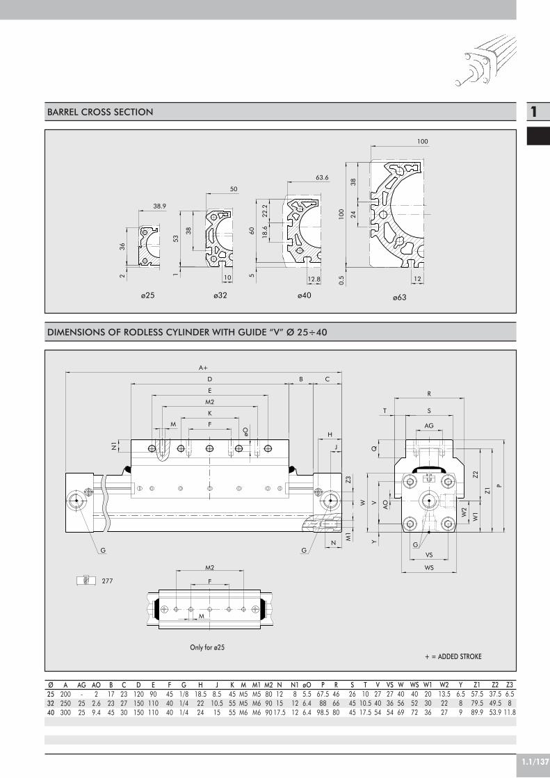
1.1/137
1
DIMENSIONS OF RODLESS CYLINDER WITH GUIDE “V” Ø 25÷40
277
GGG
ST
R
Q
VS
WS
W2
øO
B
H
C
JN1
M
N
D
A+
W1
Z2
Z1
P
YM1
AOV
Z3
W
E
M2
K
F AG
M2
F
M
BARREL CROSS SECTION
+ = ADDED STROKEOnly for ø25
Ø253240
A200250300
B172345
C232730
D120150150
E90110110
F454040
G1/81/41/4
H18.52224
J8.510.515
K455555
MM5M5M6
M1M5M6M6
N121517.5
N181212
øO5.56.46.4
P67.58898.5
R466680
S264545
T1010.517.5
V274054
VS273654
W405669
WS405272
W1203036
W213.52227
Y6.589
Z157.579.589.9
Z237.549.553.9
Z36.58
11.8
M2809090
AG-2525
AO22.69.4
ø40 ø63ø32ø25
18.638 60
22.2
12.8
63.6
5 12
38
100
100
24
0.510
50
531
38.9
362

1.1/138
DIMENSIONS OF RODLESS CYLINDER WITH GUIDE “V” Ø63
G3/8 G3/8 G3/8
AB
C
D H
E
G
F
A
FB
E
CG
D
H277
430 +
32
127.
5
78
25
49.85
11.5
100
144
190
103
17
78103
M8 (8 fori)
59.548
11 14.5
120
100
240
9
257 47.5 39
M8
136.
5
+ = ADDED STROKE
Basic supplyA, B, C, D to feed to left chambersE, F, G, H to feed the right chambersNote: B, C, D, F, G and H are supplied closed with threaded plugs.
If you modify the position of an inner plug following the instructions provided with the cylinder, you can arrange:
all feeds from the left all feeds from the rightA, B feed the left chambers E, F feed the right chambers
C, D feed the right chambers G, H feed the left chambers
DIMENSIONS OF RODLESS CYLINDER WITH GUIDE “V” + ADJUSTABLE LIMIT SWITCH AND DECELERATORS
Stroke
16222525
Max. cushioned forcefor stroke [J]
265490
160
for hour [J]34000537007000091000
Max. impactforce [N]
280037505500
11120
Max. thrustforce [N]
530890
15502220
Ø
25324063
B Max
84110120122
C1
35456065
D
M14x1.5M20x1.5M25x1.5M36x1.5
W7
537489128.5
W8
676075153
WS4
506480103
Z4
81012.516
Z5
9.812.212.719
F
80100100120
C2
91114-
278
WS4
Z4
Z5
F
B max C2
W7
D C1
W8
D
Z4
Z5
WS4
F
B max C2
W7
W8
C1
FZ4
WS4Z5
C1D
W7
W8
Ø63Ø25 Ø32; Ø40

1.1/139
1KEY TO CODES
CYL 2 7
27 Rodlesscylinder
7
7 Double-acting cushionedMagnetic with guide “V”
8 Double-acting cushionedMagnetic with guide “V” +
adjustable limit switchesand decelerator
2 5
25324063
C N
TYPE STROKE
0 0 5 00
0 magneticS non-
magneticG* No stick
slip
CONFIGURATIONBORE
Ø 25÷40:from 100 to 5700 mmØ63from 100 to 5500 mm
C
*For speed ! 0.2 m/s **For speed " 1m/s
ACCESSORIES
FOOT Ø 25
UH
AH
TR
AT
H +
AU
ø AB
AO
FOOT Ø 32; 40
ø AB
AO
H +
AU
TR
AV
UH
AH
AT
Code
W0950257001
Ø
25
ØAB
5.5
AH
2
AO
22
AT
2.5
AU
6
TR
27
UH
40
H
232
Code
W0950327001W0950407001
Ø
3240
ØAB
6.69
AH
42
AO
2525
AT
2020
AU
811.5
TR
3654
UH
5171
H
284327
AV
2030
Weight [g]
32
Note: Individually packed with 2 screws.
Note: Individually packed with 2 screws.
Weight [g]
88112
FOOT Ø 63
UH
TR
ø AB
AT
AUAO
H +
Code
W0950637001
Ø
63
ØAB
11
AT
7
AO
64
TR
78
UH
103
H
460
Note: Individually packed with 2 screws.
Weight [g]
360
+ = ADDED STROKE
INTERMEDIATE SUPPORT Ø 25
UH
øAB
AT
TR AO AH
Code
0950254094
Ø
25
ØAB
5.5
AH
4
AO
20
AT
6
TR
48
UH
60
Weight [g]
6
Note: Individually packed.
+ = ADDED STROKE
+ = ADDED STROKE
N NBRV** FKM/FPM
AU
15

1.1/140
INTERMEDIATE SUPPORT Ø 32; 40
øAB
AHTR
AT
AV
AOUH
Note: plate supplied complete with 4 screws, 4 fixing plates
Code
W0950327032W0950407032
INTERMEDIATE SUPPORT Ø 63
øAB
AT
AO
UH
TR
Ø
63
ØAB
8.5
AH
7.5
AO
55
AT
7.5
TR
78
UH
103
Weight [g]
330
Code
W0950637032
RETRACTABLE SENSOR WITHINSERTION FROM ABOVE
Weight [g]
72104
Ø
3240
ØAB
6.56.5
AH
57
AO
5560
AT
88
TR
61.570÷75
UH
7385
AV
4045
This type of sensor can be inserted in the slot of the sensor from above. This means thecylinder heads do not require a through opening.
Code
FOR Ø25W0952022500W0952128184W0952025500W0952029395
FOR Ø32÷63W0952022180W0952028184W0952025390W0952029394W0952125556
Description
REED N.O. SENSOR, VERTICAL INSERTION 2.5mREED N.O. SENSOR, VERTICAL INSERTION 300 mm M8HALL N.O. SENSOR, VERTICAL INSERTION 2.5mHALL N.O. SENSOR, VERTICAL INSERTION 300 mm M8
REED N.O. SENSOR, VERTICAL INSERTION 2.5mREED N.O. SENSOR, VERTICAL INSERTION 300 mm M8HALL N.O. SENSOR, VERTICAL INSERTION 2.5mHALL N.O. SENSOR, VERTICAL INSERTION 300 mm M8HALL N.O. SENSOR, VERTICAL INSERTION 2m ATEX
Note: plate supplied complete with 4 screws, 4 fixing plates
black
HALL EFFECT+
+
brown
blue
PNP
blue
black
-
blue
brown
brown
34
1
REED EFFECT+
+-
brown
3blue 4
1
M8
M8
WIRING DIAGRAM TECHNICAL DATA
Type of contactSwitchSupply voltage (Ub) VPower WVoltage variationVoltage drop VInput current mAOutput current mASwitching frequency HzShort-circuit protectionOver-voltage suppressionPolarity inversion protectionEMCLED displayMagnetic sensitivityRepeatabilityDegree of protection (EN 60529)Vibration and shock resistanceTemperature range °CSensor capsule material2.5m/2m connecting cableConnecting cable with M8x1Wire NO.
Reed Effetto Hall Effetto HallN.O. N.O. N.O.
- PNP PNP10 ÷ 30 AC/DC 10 ÷ 30 DC 18 ÷ 30 DC3 (peak valve=6) 3 ! 1.7
- ! 10% di Ub ! 10% di Ub- ! 2 ! 2.2- ! 10 ! 10
! 100 ! 100 ! 70! 400 ! 5000 1000
- Yes Yes- Yes Yes- Yes Yes
EN 60 947-5-2 EN 60 947-5-2 EN 60 947-5-2Yellow Yellow Yellow
2,8 mT ±25% 2,8 mT ±25% 2.6! 0,1 mT ! 0,1 mT ! 0,1 (Ub and ta fixed)
IP 67 IP 67 IP 68, IP 69K30 g, 11 ms, 10÷55 Hz, 1mm 30 g, 11 ms, 10÷55 Hz, 1mm 30 g, 11 ms, 10÷55 Hz, 1mm -25 ÷+75 -25 ÷ +75 -20 ÷ +45
PA66 + PA6I/6T PA66 + PA6I/6T PAPVC; 2 x 0,12 mm2 PVC; 3 x 0,14 mm2 PVC; 3 x 0,12 mm2
Polyurethane; 2 x 0,14 mm2 Polyurethane; 3 x 0,14 mm2 -2 3 3
ATEX

1.1/141
1SENSOR SUPPORT Ø 25 Code
0950164001
Description
SENSOR SUPPORT STD
Note: Supplied with 1 stud pin, 2 screws
ADJUSTABLE LIMIT SWITCH ANDSHOCK ABSORBERS KIT Description
ACC. RODLESS CYLINDER LIMIT SWITCH AND SHOCK ABSORBERS Ø 25ACC. RODLESS CYLINDER LIMIT SWITCH AND SHOCK ABSORBERS Ø 32ACC. RODLESS CYLINDER LIMIT SWITCH AND SHOCK ABSORBERS Ø 40ACC. RODLESS CYLINDER LIMIT SWITCH AND SHOCK ABSORBERS Ø 63
Code
0950254004095032400409504040040950634004
Weight [g]
2604607301620
KIT FOR CYLINDER ASSEMBLYWITH SENSOR SLOTS Description
ACC. M3 T-SLOTTED FIXING PLATEACC. M4 T-SLOTTED FIXING PLATE
Code
09500030010950003002
Note: Individually packed
Weight [g]
11
5.8 500
4.9
SLOT STRIP
Note: the code corresponds to 1 piece
Code
W0950000160
Description
SLOT STRIP 500 mm
SHOCK ABSORBERS Description
Shock absorbers PR025 MC2 + nut M14x1.5Shock absorbers PR050 MC2 + nut M20x1.5Shock absorbers PR0100 MF2 + nut M25x1.5Shock absorbers PR0125 MF3 + nut M36x1.5
Code
0950004004095000400509500040060950004007
Bore
ø25ø32ø40ø63
Ø25÷40 Ø63
Note: Supplied complete with 1 shock absorber support, 1 standard shock absorber , 1 shockabsorber nut, 1 limit switch grub screw, 1 grub screw nut ( 2 for ø63) , 1 bracket, 1 bracket screw,4 locking grub screws (for Ø 25), 4 locking plates and 4 screws (for Ø 32 and Ø 40).For graphs to help shock absorbers, see page 1.1/124

1.1/142
“NEW GENERATION” CYLINDER
BAN
DS
SUPP
ORTBlack
OrangeLight GreyDark Grey
White
Yellow
PIST
ON
Type A
Type 0
Type 1
Type 2
Type 3
X YSpare parts labelon one cylinder side
! Bands support Kit" Piston kit# $ % & ' ( NBR gaskets Kit (FKM/FPM for ')# $ % & ' ( FKM/FPM gaskets Kit) * Bands Kit (inner/outer)+ “V” guide plate Kit
SPARE PARTS
10
9 1
67
3 5 4 29 8 11 108 X
Y
BANDS SUPPORT KIT POS 1 (Y)
Ø25324063
* For ø63, the kit includes a strip support and a shim in the colour ordered.Therefore, two kits must be ordered for each cylinder.
NOTES
BANDS KIT (inner and outer)pos 8-9Ø
25324063
Code
0090256…0090326…0090406…0090636… ...= STROKE
CodeWhite
009025508000903250800090405080
*0090635080
CodeBlack
009025508100903250810090405081
*0090635081
CodeOrange
009025508200903250820090405082
*0090635082
CodeLight grey
009025508300903250830090405083
*0090635083
CodeDark grey
009025508400903250840090405084
*0090635084
CodeYellow
009025508500903250850090405085
*0090635085
Ø25324063
CodeType 0 (0 rings)0090255015009032501500904050150090635015
CodeType 1 (1 rings)0090255016009032501600904050160090635016
CodeType 2 (2 rings)0090255017009032501700904050170090635017
CodeType 3 (3 rings)0090255018009032501800904050180090635018
CodeType A (4 rings)00902550190090325019
––
PISTON KIT POS 2 (X)
Ø
25324063
Code
0090255060009032506000903250600090635060
“V” GUIDE PLATE KIT posn. 11
Ø
25324063
Code
0090255022009032502200904050220090635022
NBR GASKET KIT pos. 3-4-5-6-7-10 FKM/FPM GASKET KITpos. 3-4-5-6-7-10
Ø
25324063
Code
0090255023009032502300904050230090635023
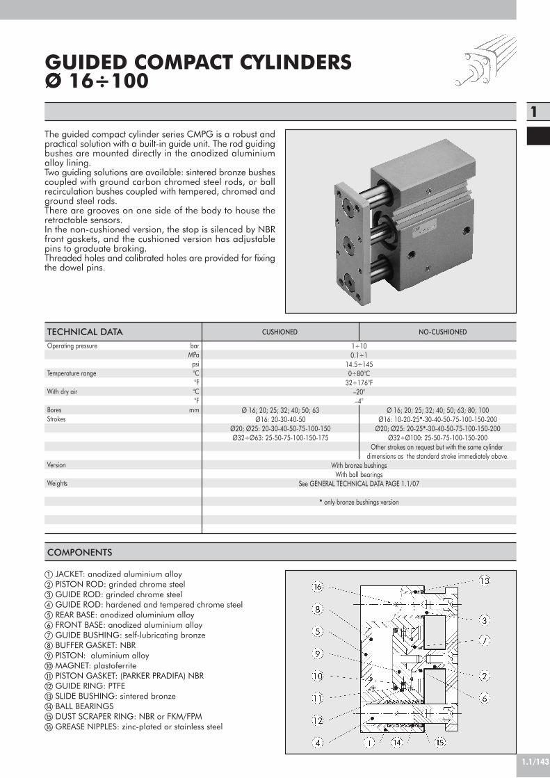
1.1/143
1
GUIDED COMPACT CYLINDERSØ 16÷100
The guided compact cylinder series CMPG is a robust andpractical solution with a built-in guide unit. The rod guidingbushes are mounted directly in the anodized aluminiumalloy lining.Two guiding solutions are available: sintered bronze bushescoupled with ground carbon chromed steel rods, or ballrecirculation bushes coupled with tempered, chromed andground steel rods.There are grooves on one side of the body to house theretractable sensors.In the non-cushioned version, the stop is silenced by NBRfront gaskets, and the cushioned version has adjustablepins to graduate braking.Threaded holes and calibrated holes are provided for fixingthe dowel pins.
COMPONENTS
! JACKET: anodized aluminium alloy" PISTON ROD: grinded chrome steel# GUIDE ROD: grinded chrome steel$ GUIDE ROD: hardened and tempered chrome steel% REAR BASE: anodized aluminium alloy& FRONT BASE: anodized aluminium alloy' GUIDE BUSHING: self-lubricating bronze( BUFFER GASKET: NBR) PISTON: aluminium alloy* MAGNET: plastoferrite+ PISTON GASKET: (PARKER PRADIFA) NBR, GUIDE RING: PTFE- SLIDE BUSHING: sintered bronze. BALL BEARINGS/ DUST SCRAPER RING: NBR or FKM/FPM0 GREASE NIPPLES: zinc-plated or stainless steel
1÷100.1÷1
14.5÷1450÷80°C
32÷176°F–20°–4°
Ø 16; 20; 25; 32; 40; 50; 63 Ø 16; 20; 25; 32; 40; 50; 63; 80; 100 Ø16: 20-30-40-50 Ø16: 10-20-25*-30-40-50-75-100-150-200
Ø20; Ø25: 20-30-40-50-75-100-150 Ø20; Ø25: 20-25*-30-40-50-75-100-150-200Ø32÷Ø63: 25-50-75-100-150-175 Ø32÷Ø100: 25-50-75-100-150-200
Other strokes on request but with the same cylinderdimensions as the standard stroke immediately above.
With bronze bushingsWith ball bearings
See GENERAL TECHNICAL DATA PAGE 1.1/07
* only bronze bushings version
TECHNICAL DATAOperating pressure bar
MPapsi
Temperature range °C°F
With dry air °C°F
Bores mmStrokes
Version
Weights
CUSHIONED NO-CUSHIONED

1.1/144
F
F
MAXIMUM SIDE LOADGuide unit
BushesBallsBushesBallsBushesBallsBushesBallsBushesBallsBushesBallsBushesBallsBushesBallsBushesBalls
NB: Forces are expressed in N
Ømm
16
20
25
32
40
50
63
80
100
Stroke (mm)
MAXIMUM TORQUE ON PLATEGuide unit
BushesBallsBushesBallsBushesBallsBushesBallsBushesBallsBushesBallsBushesBallsBushesBallsBushesBalls
NB: Forces are expressed in Nm
Ømm
16
20
25
32
40
50
63
80
100
Stroke (mm)
ASSEMBLY OPTIONS
A B
If the compact guided cylinder is mounted as shown in figure A,there need to be two through holes in the frame for the guidecolumns.
10
3529––––––––––––––––
20
293152567172––––––––––––
25
27–
50–
67–
19789
19789
295138295138354236540471
30
262745486162––––––––––––
40
233839795478––––––––––––
50
203435704873
16860
16860
25689
25689
305158471314
75
162958547860
138276138276216393216393256864413
1374
100
142449506652
109217109217177314177314207687344
1074
150
10123827503778
13878
138125184125184153413254629
200
88
3132413065
11065
110103148103148128335213511
175
––––––
7012270
122112163112163
––––
10
0.510.74
–––––––´–––––––––
20
0.450.600.921.281.551.98
––––––––––––
25
0.40–
0.85–
1.42–
3.941.974.402.467.363.457.853.94
11.789.34
22.5521.56
30
0.360.500.791.081.321.70
––––––––––––
40
0.320.720.721.781.182.16
––––––––––––
50
0.280.650.641.591.042.202.95
13.451.455.9
2.446.382.469.805.88
19.6213.73
75
0.240.541.051.241.701.662.462.962.966.384.9010.85.40
11.777.84
31.3816.6863.72
100
0.200.450.90
11.441.4
1.972.442.465.44.4
8.354.99.3
6.8824.514.749.1
150
0.460.350.690.611.101.021.552.401.70
33
4.53.45
5.3010.4010.6526.6
200
0.120.250.560.490.900.821.242.181.402.402.503.602.80
44.4011.78.9021.6
175
––––––
1.382.431.552.732.784.063.054.46
––––

1.1/145
1STOPPER FUNCTIONS
V
m m
V
l = 5
0 m
m
LIFTING FUNCTIONS
P P
LL
The graph refers from 25 to 50 mm-stroke cylinders with ball re-circulation guide unit.
100
5020 30 40101
50
10
5
1
500
1000
3000
m (K
g)
V (m/min)
ø16
ø20
ø25
ø32
ø40
ø50
ø63
ø80ø100
10
100101 300
1000
100
4000
ø63
ø100
ø50
ø16
ø20
ø25
ø32ø40
ø80
L (mm)
P (N
)
1
P (N
)
L (mm)
ø63
1
ø100
ø50
1
10
ø16
ø20
ø25
ø32ø40
ø80
10010
1000
100
4000
300
The graph refers from 75 to 100 mm-stroke cylinders with ball re-circulation guide unit.
4000
ø63
ø100
ø50
ø16
ø20
ø25
ø32ø40
ø80
L (mm)
P (N
)
11 10 100 300
1000
100
10
Mov
ing
mas
s (k
g)
Conveying speed (m/min)
The graph refers to a 50mm-stroke cylinder.
Ecce
ntric
load
(N)
Distance (mm)
Ecce
ntric
load
(N)
Distance (mm)
Ecce
ntric
load
(N)
Distance (mm)
The graph refers to 50mm-stroke cylinders with bushing guide unit.

1.1/146
W143___2
W143___3
N°
4 x
F1
Dep
th T
E3
R
A
øQ
N
BE2GD
M1
M
L+
P+
C+
I
øS
C1
B1
E
F
N° 4 x F1
H
E1+
N°
4 x
F2
H
A1Z1 Z2
N° 4 x F1 Depth U
M2 M3
K
DIMENSIONS OF NO-CUSHIONED COMPACT GUIDED CYLINDERS
+ = ADD THE STROKE
Ø S
Ø1620253240506380100
A3336425151597292112
A12529384949566988108
B647488114124140150188224
B1627286112122138148185221
C333737.537.544444956.566
C1101010101012121616
D999911111115.519
E161826303040506080
E17101051010101515
E252607096106120130160190
E3546476100110124132166200
FM51/81/81/81/81/41/43/83/8
F1M5M5M6M8M8M10M10M12M14
F2–––M6M6M8M8M10M10
G10.51111.512.51414141923
H–––32.53846.556.57289
I3846568090100110140170
L***73.573.5838393105
M222632383844445662
M14252628090100110140170
N89815212731.53740
P454949.549.556586374.584
ØQ81012161620202530
R131316.5161717202125
T202025202025253035
U889111112.5151821
* =Ø162025
L stroke0÷50
4549
49.5
75÷200–
7679.5
M215172125.525.529.5364656
M318192125.525.529.5364656
Z15.54.521.51.51.51.522
Z22.52.521.51.51.51.522
KH7
455666668
Ø1620253240506380100
Ø
1620253240506380
100
Bronze-Bushings
101216202025252835
BallBearings
1010162020****2530
** for stroke 25 e 50 = 20for stroke !75 = 25

1.1/147
1
W143___5
W143___4
E3
A
N
BE2
øS
B1E
N° 4 x F1
H
N°
4 x
F2
H
A1Z1 Z2
N°
4 x
F1
Dep
th T
RøQ
GD
M1
M
L+
P+
C+
I
C1
E1+
N° 4 x F1 Depth U
M2 M3
F
K
DIMENSIONS OF CUSHIONED COMPACT GUIDED CYLINDERS
+ = ADD THE STROKE
Ø16202532405063
A33364251515972
A125293849495669
B647488114124140150
B1627286112122138148
C586262.562.5696974
C110101010101212
D9999111111
E16182630304050
E132353530353535
E252607096106120130
E3546476100110124132
FM51/81/81/81/81/41/4
F1M5M5M6M8M8M10M10
F2–––M6M6M8M8
G10.51111.512.5141414
H–––32.53846.556.5
I4046568090100110
L***106.5106.5118118
M22263238384444
M14252628090100110
N89815212731.5
P!7878.582.5899398
ØQ8101216162020
R13131416.5171720
T20202520202525
U889111112.515
* =Ø162025
L stroke0÷50
7074
74.5
75÷150–
105.5108.5
M215172125.525.529.536
M318192125.525.529.536
Z15.54.521.51.51.51.5
Z22.52.521.51.51.51.5
KH7
4556666
Ø16202532405063
! for bronze bushings = 78for ball bearing = 75
Ø
16202532405063
Bronze-Bushings
10121620202525
BallBearings
1010162020****
Ø S
** for stroke 25 e 50 = 20for stroke !75 = 25

1.1/148
KEY TO CODES
W 1 4 3
TYPE
0 3 2
16202532405063*80
*A1=100
DIAMETER
2
2 bronzebushings
3 ball bearings4 cushioned with
brass bushings5 cushioned with
ball bearings
VERSION
0 2 5
CUSHIONED VERSIONØ 16: 20, 30, 40, 50Ø 20÷25: 20, 30, 40, 50, 75, 100, 150Ø 32÷63: 25, 50, 75, 100, 150, 175NOT CUSHIONED VERSION!
Ø 16: 10, 20, "25, 30, 40, 50, 75, 100, 150, 200Ø 20÷25: 20, "25, 30, 40, 50, 75, 100, 150, 200Ø 32÷100: 25, 50, 75, 100, 150, 200
STROKE
!Other strokes on request but with the samecylinder dimensions as the standard strokeimmediately above.
* Not cushioned version only" Bronze bushings version only
RETRACTABLE SENSOR WITH INSERTION FROM ABOVE
BAR FOR GROOVING
5.8 500
4.9
DescriptionBAR FOR GROOVING L=500 mm
CodeW0950000160
DescriptionHALL N.O. SENSOR, VERTICAL INSERTION 2.5mHALL N.O. SENSOR, VERTICAL INSERTION 300 mm M8REED N.O. SENSOR, VERTICAL INSERTION 2.5mREED N.O. SENSOR, VERTICAL INSERTION 300 mm M8HALL N.O. SENSOR, VERTICAL INSERTION 2m ATEX
CodeW0952025390W0952029394W0952022180W0952028184W0952125556
Note: the code corresponds to 1 piece
This type of sensor can be inserted in the slot of the sensor from above. This means thecylinder heads do not require a through opening.
ACCESSORIES
black
HALL EFFECT+
+
brown
blue
PNP
blue
black
-
blue
brown
brown
34
1
REED EFFECT+
+-
brown
3blue 4
1
M8
M8
WIRING DIAGRAM TECHNICAL DATA
Type of contactSwitchSupply voltage (Ub) VPower WVoltage variationVoltage drop VInput current mAOutput current mASwitching frequency HzShort-circuit protectionOver-voltage suppressionPolarity inversion protectionEMCLED displayMagnetic sensitivityRepeatabilityDegree of protection (EN 60529)Vibration and shock resistanceTemperature range °CSensor capsule material2.5m/2m connecting cableConnecting cable with M8x1Wire NO.
Reed Effetto Hall Effetto HallN.O. N.O. N.O.
- PNP PNP10 ÷ 30 AC/DC 10 ÷ 30 DC 18 ÷ 30 DC3 (peak valve=6) 3 ! 1.7
- ! 10% di Ub ! 10% di Ub- ! 2 ! 2.2- ! 10 ! 10
! 100 ! 100 ! 70! 400 ! 5000 1000
- Yes Yes- Yes Yes- Yes Yes
EN 60 947-5-2 EN 60 947-5-2 EN 60 947-5-2Yellow Yellow Yellow
2,8 mT ±25% 2,8 mT ±25% 2.6! 0,1 mT ! 0,1 mT ! 0,1 (Ub and ta fixed)
IP 67 IP 67 IP 68, IP 69K30 g, 11 ms, 10÷55 Hz, 1mm 30 g, 11 ms, 10÷55 Hz, 1mm 30 g, 11 ms, 10÷55 Hz, 1mm -25 ÷+75 -25 ÷ +75 -20 ÷ +45
PA66 + PA6I/6T PA66 + PA6I/6T PAPVC; 2 x 0,12 mm2 PVC; 3 x 0,14 mm2 PVC; 3 x 0,12 mm2
Polyurethane; 2 x 0,14 mm2 Polyurethane; 3 x 0,14 mm2 -2 3 3
ATEX

1.1/149
1ISO 6432 stainless steel micro-cylinders are available invarious versions with a wide range of accessories• with or without magnet execution• double-acting - single or through-rod• gaskets: Polyurethane or FKM/FPM (for high temperatures)• fixing accessories
TECHNICAL DATAOperating pressureTemperature range °CFluidBores mmDesignStandard strokes ! mmVersionsMagnet for sensors
COMPONENTS
! PISTON ROD: AISI 316 steel" HEAD:AISI 304 steel# PISTON ROD GASKET: polyurethane or
FKM/FPM$ GUIDE BUSHING: sintered bronze% JACKET: AISI 304 steel& PISTON: brass' PISTON GASKET: polyurethane
or FKM/FPM( MAGNET: plastoferrite) Static O-rings: NBR or FKM/FPM
8 7 6591 23 4
POLYURETHANE FKM/FPM
max 10 bar (max 1 MPa) –10÷+80 –10÷+150 (non-magnetic cylinders)
Unlubricated air. Lubrication, if used, must be continuousØ 16 ; Ø 20 ; Ø 25Chamfered heads
max 500Double-acting, Double-acting through-rod
All versions come complete with magnet. Supplied without magnet on request.! Maximum recommended strokes. Higher values can create operating problems
STAINLESS STEEL MINI-CYLINDERSERIES “ISO 6432” Ø 16÷25 mm
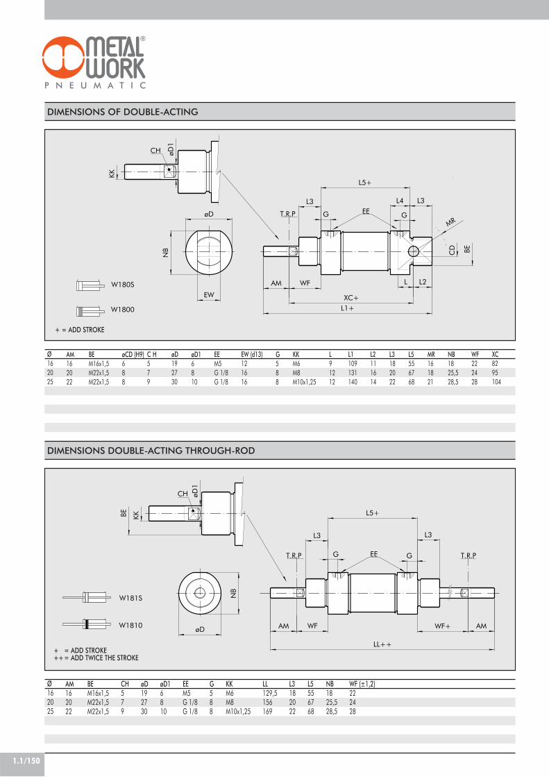
1.1/150
DIMENSIONS OF DOUBLE-ACTING
EE
MRT.R.P
CH
W180S
W1800
WF L
L5+
øD
øD1
KK
EW
L1+
AM
L3 L4
L2
L3
BECD
XC+
GG
NB
Ø162025
øD16810
G588
BEM16x1,5M22x1,5M22x1,5
øCD (H9)688
AM162022
EEM5G 1/8G 1/8
L91212
KKM6M8M10x1,25
L5556768
L3182022
NB1825,528,5
C H579
MR161821
WF222428
L2111614
L1109131140
EW (d13)121616
øD192730
XC8295104
DIMENSIONS DOUBLE-ACTING THROUGH-ROD
T.R.PEET.R.P
CH
W181S
W1810 WF+øD
NB
WF
øD1
KKBE
AM
G
L3L3
G
L5+
AM
LL++
Ø162025
øD16810
G588
BEM16x1,5M22x1,5M22x1,5
øD192730
AM162022
EEM5G 1/8G 1/8
LL129,5156169
KKM6M8M10x1,25
L5556768
WF (±1,2)222428
L3182022
NB1825,528,5
CH579
+ = ADD STROKE
+ = ADD STROKE++= ADD TWICE THE STROKE

1.1/151
1KEY TO CODES
STAINLESS STEEL LEG MODEL A
R
T.R.
P.
AU *
XS * US *
TR *
NH
*
S
AO *
ø D
ø AB *
W 1 8
Stainless steelcylinder
0
0 DEM1 DEM
through-rod
DEM: Magnetic double-acting (non-cushioned)! Maximum recommended strokes. Higher values can create operating problems
ACCESSORIES: FIXINGS
STAINLESS STEEL FLANGE MODEL C
T.R.
P.
UR
*
ø D
TF *
UF *
ø FB *
S
W *
Ø
162025
W (±1.4)
181923
FB
5.56.66.6
D
162222
TF
405050
UF
526666
UR
304040
S
455
Code
W095X120002W095X200002W095X200002
Weight [g]
265252
Ø
162025
Code
W095X120001W095X200001W095X200001
*ISO 6432 values
1 6
162025
DIAMETER
0
VERSION
0 0 2 0
! Ø 16÷25 stroke 0÷500 mm
STROKETYPE
0 Standard (magnetic)S Not magneticV FKM/FPM gasketI Longer piston rod
Note: Individually packed
*ISO 6432 values
Note: Individually packed
AO
688
NH
202525
XS (±1.4)
223640
AU
141717
D
16,122,122,1
R
132020
US
425454
S
455
ØAB
5,56,66,6
TR
324040
Weight [g]
429090

1.1/152
RT.R.
P.
AO
LGN
H
øAB
1
øAB +0.18-0 TR ±0.1
MO
N +0.20
S ±
0.1
H
F
CH
H
F
CH
STAINLESS STEEL COUNTER-HINGE MODEL BC Code
W095X120005W095X200005W095X200005
Ø
162025
AO
244
LG
253232
TR
152020
NH
273030
MO
243131
AB1
688
AB
5.56.66.6
R
71010
S
344
Weight [g]
407878
Note: Supplied complete with 1 pin and 2 snap rings
STAINLESS STEEL NUT FOR HEADS Ø
162025
F
M16x1.5M22x1.5M22x1.5
H
588
Code
W095X120010W095X200010W095X200010
Note: Individually packed
CH
222727
STAINLESS STEEL NUT FOR PISTON RODS Ø
162025
CH
101317
F
M6M8M10x1.25
H
456
Weight [g]
137
Code
W095X120011W095X200011W095X322011
Note: Individually packed
STAINLESS STEEL FORK-MODEL GK-M Code
W095X120020W095X200020W095X322020
Note: Individually packed
Ø
162025
Ø M
6810
C
121620
B
6810
A
121620
L
314252
F
243240
D
M6M8M10x1.25
N
12.116.116.1
A
L
F
øM
D
C
B
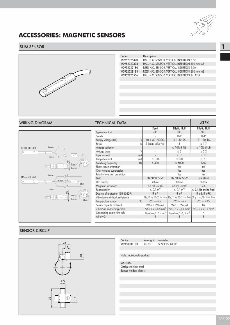
1.1/153
1
ACCESSORIES: MAGNETIC SENSORS
9.5
1535
13
1422
Note: Individually packed
MATERIALCirclip: stainless steelSensor holder: plastic
SENSOR CIRCLIP
Alesaggio8÷63
CodiceW0950001103
ModelloSENSOR CIRCLIP
SLIM SENSOR
DescriptionHALL N.O. SENSOR, VERTICAL INSERTION 2.5mHALL N.O. SENSOR, VERTICAL INSERTION 300 mm M8REED N.O. SENSOR, VERTICAL INSERTION 2.5mREED N.O. SENSOR, VERTICAL INSERTION 300 mm M8HALL N.O. SENSOR, VERTICAL INSERTION 2m ATEX
CodeW0952025390W0952029394W0952022180W0952028184W0952125556
black
HALL EFFECT+
+
brown
blue
PNP
blue
black
-
blue
brown
brown
34
1
REED EFFECT+
+-
brown
3blue 4
1
M8
M8
WIRING DIAGRAM TECHNICAL DATA
Type of contactSwitchSupply voltage (Ub) VPower WVoltage variationVoltage drop VInput current mAOutput current mASwitching frequency HzShort-circuit protectionOver-voltage suppressionPolarity inversion protectionEMCLED displayMagnetic sensitivityRepeatabilityDegree of protection (EN 60529)Vibration and shock resistanceTemperature range °CSensor capsule material2.5m/2m connecting cableConnecting cable with M8x1Wire NO.
Reed Effetto Hall Effetto HallN.O. N.O. N.O.
- PNP PNP10 ÷ 30 AC/DC 10 ÷ 30 DC 18 ÷ 30 DC3 (peak valve=6) 3 ! 1.7
- ! 10% di Ub ! 10% di Ub- ! 2 ! 2.2- ! 10 ! 10
! 100 ! 100 ! 70! 400 ! 5000 1000
- Yes Yes- Yes Yes- Yes Yes
EN 60 947-5-2 EN 60 947-5-2 EN 60 947-5-2Yellow Yellow Yellow
2,8 mT ±25% 2,8 mT ±25% 2.6! 0,1 mT ! 0,1 mT ! 0,1 (Ub and ta fixed)
IP 67 IP 67 IP 68, IP 69K30 g, 11 ms, 10÷55 Hz, 1mm 30 g, 11 ms, 10÷55 Hz, 1mm 30 g, 11 ms, 10÷55 Hz, 1mm -25 ÷+75 -25 ÷ +75 -20 ÷ +45
PA66 + PA6I/6T PA66 + PA6I/6T PAPVC; 2 x 0,12 mm2 PVC; 3 x 0,14 mm2 PVC; 3 x 0,12 mm2
Polyurethane; 2 x 0,14 mm2 Polyurethane; 3 x 0,14 mm2 -2 3 3
ATEX

1.1/154
STAINLESS STEEL ROUND CYLINDERSERIES “RNDC” Ø 32 TO 63 mm
Stainless steel clean profile cylinders available in differentversions:• with or without magnet execution• double-acting - single or through-rod• pneumatic cushioning on request• gaskets:Polyurethane or FKM/FPM (for high temperatures).
TECHNICAL DATAOperating pressureTemperature range °CFluidBores mmDesignStandard strokes ! mmVersionsMagnet for sensors
COMPONENTS
! PISTON ROD: AISI 316 steel" PISTON ROD GASKET: polyurethane or FKM/FPM# GUIDE BUSHING: sintered bronze$ JACKET: AISI 304 steel% PISTON: aluminium& MAGNET: plastoferrite' PISTON GASKET: polyurethane or FKM/FPM( ) HEAD:AISI 304 steel* BUFFER: polyurethane+ GUIDE RING: PTFE
7 511 68 4102 931
POLYURETHANE FKM/FPM
max 10 bar (max 1 MPa) –10÷+80 –10÷+150 (non-magnetic cylinders)
Unlubricated air. Lubrication, if used, must be continuousØ 32 ; Ø 40 ; Ø 50 ; Ø63
Chamfered headsmax 500
Double-acting, Double-acting through-rodAll versions come complete with magnet. Supplied without magnet on request.
! Maximum recommended strokes. Higher values can create operating problems

1.1/155
1DIMENSIONS OF DOUBLE-ACTING
W180S
W1800
CH
1
1
A
N
G
R +
L +
T
R +
E
DOD
F
PSM
I +
V
W
DIMENSIONS DOUBLE-ACTING THROUGH-ROD
1
1
CH
1
W181S
W1810
R +
T +
W +
T
D S
E
M
VF
R +
PG O
W
V
F
L ++
A
I +
+ = ADD STROKE
+ = ADD STROKE++= ADD TWICE THE STROKE
Ø32405063
DM30x1.5M38x1.5M45x1.5M45x1.5
EM8x1M10x1M12x1.5M14x1.5
F20243232
Ø G30384545
CH110131717
I96113120124
L168198220224
MM10x1.5M12x1.75M16x2M16x2
N14161818
OG1/8G1/4G1/4G3/8
Ø P38465770
R78899698
Ø S12162020
T47576263
V30353838
W38455050
L1212251284288
A36.5445567.5

1.1/156
KEY TO CODES
W 1 8
Stainless steelcylinder
0
0 DEM1 DEM
through-rod
DEM: Magnetic double-acting (non-cushioned)! Maximum recommended strokes. Higher values can create operating problems
3 2
32405063
0 0 0 5 0
! Ø 32÷63 stroke 0÷500 mm
0 Standard (magnetic)S Not magneticV FKM/FPM gasketI Longer piston rod
R
L +
G M
I
H
B
D
F
øE
A
C
SW
ACCESSORIES: FIXINGS
A +
L +
B
M
G
I
E
OH
N
C
D
F
STAINLESS STEEL LEG MODEL AC
STAINLESS STEEL COUNTER-HINGE MODEL BC
+ = ADD STROKE
Code
W095X320005W095X400005W095X500005W095X630005
Ø
32405063
A
40505465
B
35404550
C
24303435
D
4566
E
7999
F
8101015
G
12131416
H
46.156.169.182.1
I
20283642
L
125146158161
M
58.170.186.199.1
R
12131416
Nota: Supplied complete with 2 screws
+ = ADD STROKE
Code
W095X320002W095X400002W095X500002W095X630002
Ø
32405063
A
124153160164
B
48606464
C
7101010
D
4566
E
14202020
F
52607076
G
7999
H
14182020
I
28304050
L
148178190194
M
66809096
N
49587080
O
28334045
Note: Individually packed
DIAMETERVERSION STROKETYPE

1.1/157
1
B C
A
H
F
CH
CH
H
L4
L1 +
D
A
E
F
STAINLESS STEEL HEAD RING NUT MODEL G Ø
32405063
A
M30x1.5M38x1.5M45x1.5M45x1.5
B
45525858
C
7899
Code
W095X320010W095X400010W095X500010W095X500010
Note: Individually packed
Code
W095X320020W095X400020W095X500020W095X500020
Ø
32405063
Ø M
10121616
C
20243232
B
10121616
A
20243232
L
52628383
F
40486464
D
M10x1.5M12x1.75M16x2M16x2
STAINLESS STEEL FORK-MODEL GK-M
Note: Individually packed
STAINLESS STEEL NUT FOR PISTON RODS Ø
32405063
CH
17192424
F
M10x1.5M12x1.75M16x2M16x2
H
6788
Weight [g]
6122020
Code
W095X320011W095X400011W095X500011W095X500011
Note: Individually packed
Code
W095X320007W095X400007W095X500007W095X630007
Ø
32405063
E
1416.52026
D
89.51113
A
M8X1M10X1M12X1.5M14X1.5
øF
10121416
STAINLESS STEEL OSCILLATING PIN
Note: 2- piece pack
L1
125146158161
H
51617592
L4
47576263
+ = ADD STROKE
CH
5668
A
L
F
øM
D
C
B
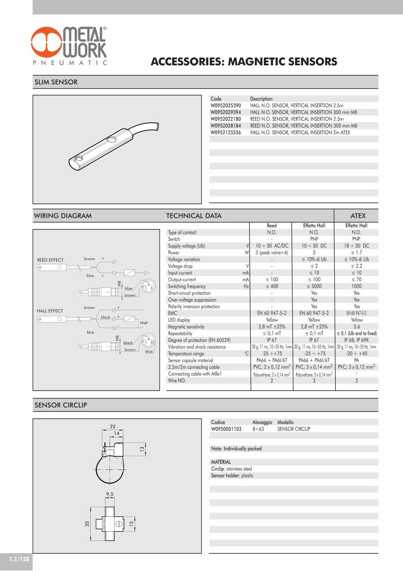
1.1/158
ACCESSORIES: MAGNETIC SENSORS
9.5
1535
13
1422
Note: Individually packed
MATERIALCirclip: stainless steelSensor holder: plastic
SENSOR CIRCLIP
Alesaggio8÷63
CodiceW0950001103
ModelloSENSOR CIRCLIP
SLIM SENSOR
DescriptionHALL N.O. SENSOR, VERTICAL INSERTION 2.5mHALL N.O. SENSOR, VERTICAL INSERTION 300 mm M8REED N.O. SENSOR, VERTICAL INSERTION 2.5mREED N.O. SENSOR, VERTICAL INSERTION 300 mm M8HALL N.O. SENSOR, VERTICAL INSERTION 2m ATEX
CodeW0952025390W0952029394W0952022180W0952028184W0952125556
black
HALL EFFECT+
+
brown
blue
PNP
blue
black
-
blue
brown
brown
34
1
REED EFFECT+
+-
brown
3blue 4
1
M8
M8
WIRING DIAGRAM TECHNICAL DATA
Type of contactSwitchSupply voltage (Ub) VPower WVoltage variationVoltage drop VInput current mAOutput current mASwitching frequency HzShort-circuit protectionOver-voltage suppressionPolarity inversion protectionEMCLED displayMagnetic sensitivityRepeatabilityDegree of protection (EN 60529)Vibration and shock resistanceTemperature range °CSensor capsule material2.5m/2m connecting cableConnecting cable with M8x1Wire NO.
Reed Effetto Hall Effetto HallN.O. N.O. N.O.
- PNP PNP10 ÷ 30 AC/DC 10 ÷ 30 DC 18 ÷ 30 DC3 (peak valve=6) 3 ! 1.7
- ! 10% di Ub ! 10% di Ub- ! 2 ! 2.2- ! 10 ! 10
! 100 ! 100 ! 70! 400 ! 5000 1000
- Yes Yes- Yes Yes- Yes Yes
EN 60 947-5-2 EN 60 947-5-2 EN 60 947-5-2Yellow Yellow Yellow
2,8 mT ±25% 2,8 mT ±25% 2.6! 0,1 mT ! 0,1 mT ! 0,1 (Ub and ta fixed)
IP 67 IP 67 IP 68, IP 69K30 g, 11 ms, 10÷55 Hz, 1mm 30 g, 11 ms, 10÷55 Hz, 1mm 30 g, 11 ms, 10÷55 Hz, 1mm -25 ÷+75 -25 ÷ +75 -20 ÷ +45
PA66 + PA6I/6T PA66 + PA6I/6T PAPVC; 2 x 0,12 mm2 PVC; 3 x 0,14 mm2 PVC; 3 x 0,12 mm2
Polyurethane; 2 x 0,14 mm2 Polyurethane; 3 x 0,14 mm2 -2 3 3
ATEX

1.1/159
1
STAINLESS STEEL CYLINDER SERIESISO 15552 (EX ISO 6431), Ø 32-100 mm
Stainless steel cylinders made to ISO 15552 available invarious versions and with a wide range of accessories:• with or without magnet execution• Double-acting – single- or through-rod• Gaskets: Polyurethane or FKM/FPM (for high temperatures)• Fixing accessories, guide units and mechanical piston
rod lock.
TECHNICAL DATAOperating pressureTemperature range °CFluidBores mmDesignStandard strokes ! mmVersionsMagnet for sensors
COMPONENTS
! PISTON ROD: AISI 316 steel" HEAD:AISI 304 steel# PISTON ROD GASKET: polyurethane or FKM/FPM$ GUIDE BUSHING: sintered bronze% JACKET: AISI 304 steel& ENBLOC GASKET: NBR or FKM/FPM' MAGNET: plastoferrite( Static O-rings: NBR or FKM/FPM) CUSHIONING GASKET: polyurethane or
FKM/FPM* CUSHIONING NEEDLE: AISI 304 steel+ TIE ROD: AISI 316 steel, NEEDLE-RETAINING RING: technopolymer
10
11
6 894 23 71 5 12
POLYURETHANE FKM/FPM
max 10 bar (max 1 MPa - 145 psi)–20÷+80 –10÷+150
Unlubricated air. Lubrication, if used, must be continuousØ 32 ;Ø 40 ; Ø 50 ; Ø 63 ; Ø 80 ; Ø 100
heads with tie rodsmax 1000
Double-acting cushioned, Double-acting through-rod cushionedAll versions come complete with magnet. Supplied without magnet on request.
! Maximum recommended strokes. Higher values can create operating problems

1.1/160
DIMENSIONS OF DOUBLE-ACTING
Ø.3240506380100
A141414161618
A1
999999
A2
11.31312.715.816.315.5
B303540454555
C263037374651
C1
182225.5253538
CH101316162121
CH1
66881010
DM10x1.25M12x1.25M16x1.5M16x1.5M20x1.5M20x1.5
D1
121620202525
E32.53846.556.57289
E1
444444
F222432324040
GG1/8G1/4G1/4G3/8G3/8G1/2
G1
M6M6M8M8M10M10
H5055657595110
L121135143158174189
L0
95105106121128138
L1
6777788996102
L2
147165180195220240
P6811.811.715.515.5
1
0
W184
CH
B
L +
G
E 1
P
A 2
L +
L +
C 1
CF
BD1
D
A
A 1H
CH
1
G 1
E
H E
DIMENSIONS DOUBLE-ACTING THROUGH-ROD
2
0
1
W185
CH
CH1
G
P
L ++
C +
C 1
D1
D
C F
A 2
B
A
A 1
H
H
E
E
G 1
L +
L +
+ = ADD STROKE
+ = ADD STROKE++= ADD TWICE THE STROKE

1.1/161
1
STAINLESS STEEL INTERMEDIATE HINGE -MODEL EN
N 3 N2
N1
N 4
N2
N 5
Code
W095X322007W095X402007W095X502007W095X632007W095X802007W095XA12007
Ø
3240506380100
N1
50637590110132
N2
121616202025
N3
121616202025
N4
222832354045
N5
657595105130145
Note: Supplied complete with 8 grub screws
STAINLESS STEEL SHORT FOOT MOUNTING
1
2
H +
øAB
AU
AO
AT
UH
TR
H +
AH
Code
W095X322001W095X402001W095X502001W095X632001W095X802001W095XA12001
Ø
3240506380100
Ø AB
79991214
AH
323645506371
+= ADD THE STROKE
AO
353647455557
AT
445566
AU
242832324141
TR
323645506375
UH
4552657595115
H1
145163175190215230
H2
143161170185210220
Note: Individually packed with 2 screws.
DEMA: Magnetic double-acting (cushioned)! Maximum recommended strokes. Higher values can create operating problems" For this version the cylinder will be not magnetic
ACCESSORIES: FIXINGS
KEY TO CODES
W 1 8
Stainless steelcylinder
4
4 DEMA5 DEMA
through-rod
3 2
3240506380
A1=100
0 0 0 5 0
0 MagneticS Standard (magnetic)V " FKM/FPM gasketI Longer piston rod
DIAMETERVERSION STROKETYPE
! Ø 32÷100 stroke 0÷1000 mm

1.1/162
R
3
B
D
øGH
9
E
S
H +
F
3
E
H
øGH
9
D
H +
+= ADD THE STROKE
STAINLESS STEEL FEMALE HINGE - MODEL B Ø
3240506380100
B
4552657595115
D
262832405060
E
222527323641
Ø G
101212161620
H3
142160170190210230
R
101212161620
S
9911111414
Ø
3240506380100
B
202226303038
C
6.66.6991111
D
101212161620
E
384150526676
G
323645506371
H
313545506070
L
323275
M
81012141417
N
101516162020
A
262832405060
E
384150526676
F
182230354050
I
515465678696
Ø
3240506380100
D
262832405060
E
222527323641
F
101212161620
Ø G
101212161620
H
9911111414
H3
143160170190210230
ØE
h 11
ØD
f7
B +0.30
C H 13
A
FEMALE HINGE INOX PIN Code
W095X322050W095X402050W095X502050W095X632050W095X802050W095XA12050
Ø
3240506380100
A
5360687898118
B
4653617191111
C
1.11.11.11.11.11.3
D
101212161620
E
9.611.511.515.215.219
Note: Supplied with 2 snap-rings
Code
W095X322003W095X402003W095X502003W095X632003W095X802003W095XA12003
Note: Supplied with 4 screws, 4 washers.WITHOUT PIN.
+= ADD THE STROKE
STAINLESS STEEL MALE HINGE - MODEL BA Code
W095X322004W095X402004W095X502004W095X632004W095X802004W095XA12004
Note: Supplied with 4 screws, 4 washers.
STAINLESS STEEL ISO COUNTER-HINGEFOR MODEL B - MODEL GS Code
W095X322008W095X402008W095X502008W095X632008W095X802008W095XA12008
Note: Individually packed
I
LF
C
A
E
G
N
B
M
H
D

1.1/163
1
øD
A1
B
B1
A
SW
STAINLESS STEE FRONT FLANGE - MODEL C Code
W095X322002W095X402002W095X502002W095X632002W095X802002W095XA12002
Ø
3240506380100
A1
647290100126150
A
8090110120150170
B
4552657595115
S
101012121616
B1
323645506375
ØD
79991214
W
162025253035
Note: Supplied with 4 screws.
øD
A1
B
B1
A
L+
S
H
F
CH
A
L
F
øM
D
C
B
STAINLESS STEE REAR FLANGE - MODEL C Code
W095X322002W095X402002W095X502002W095X632002W095X802002W095XA12002
Ø
3240506380100
A1
647290100126150
A
8090110120150170
B
4552657595115
S
101012121616
B1
323645506375
ØD
79991214
L
105115118133144154
Note: Supplied with 4 screws.
STAINLESS STEEL NUT FOR PISTON RODS Code
W095X322011W095X402011W095X502011W095X502011W095X802011W095X802011
Ø
3240506380100
F
M10x1.25M12x1.25M16x1.5M16x1.5M20x1.5M20x1.5
H
678899
CH
171924243030
Weight [g]
61220203232
Note: Individually packed
STAINLESS STEEL FORK-MODEL GK-M Code
W095X322020W095X402020W095X502020W095X502020W095X802020W095X802020
Ø
3240506380100
Ø M
101216162020
C
202432324040
B
101216162020
A
202432324040
L
52628383105105
F
404864648080
D
M10x1.25M12x1.25M16x1.5M16x1.5M20x1.5M20x1.5
Note: Individually packed
+= ADD THE STROKE

1.1/164
ACCESSORIES: MAGNETIC SENSORS
2015.7
35.1
28.4
359
11.8
Note: Individually packed
MATERIALBracket: zinc-plated aluminiumSensor holder: zinc-plated aluminiumFixing screw: zinc-plated aluminium
Alesaggio32÷100
SENSOR BRACKET
CodiceW0950001100
ModelloSENSOR BRACKET
SLIM SENSOR
DescriptionHALL N.O. SENSOR, VERTICAL INSERTION 2.5mHALL N.O. SENSOR, VERTICAL INSERTION 300 mm M8REED N.O. SENSOR, VERTICAL INSERTION 2.5mREED N.O. SENSOR, VERTICAL INSERTION 300 mm M8HALL N.O. SENSOR, VERTICAL INSERTION 2m ATEX
CodeW0952025390W0952029394W0952022180W0952028184W0952125556
black
HALL EFFECT+
+
brown
blue
PNP
blue
black
-
blue
brown
brown
34
1
REED EFFECT+
+-
brown
3blue 4
1
M8
M8
WIRING DIAGRAM TECHNICAL DATA
Type of contactSwitchSupply voltage (Ub) VPower WVoltage variationVoltage drop VInput current mAOutput current mASwitching frequency HzShort-circuit protectionOver-voltage suppressionPolarity inversion protectionEMCLED displayMagnetic sensitivityRepeatabilityDegree of protection (EN 60529)Vibration and shock resistanceTemperature range °CSensor capsule material2.5m/2m connecting cableConnecting cable with M8x1Wire NO.
Reed Effetto Hall Effetto HallN.O. N.O. N.O.
- PNP PNP10 ÷ 30 AC/DC 10 ÷ 30 DC 18 ÷ 30 DC3 (peak valve=6) 3 ! 1.7
- ! 10% di Ub ! 10% di Ub- ! 2 ! 2.2- ! 10 ! 10
! 100 ! 100 ! 70! 400 ! 5000 1000
- Yes Yes- Yes Yes- Yes Yes
EN 60 947-5-2 EN 60 947-5-2 EN 60 947-5-2Yellow Yellow Yellow
2,8 mT ±25% 2,8 mT ±25% 2.6! 0,1 mT ! 0,1 mT ! 0,1 (Ub and ta fixed)
IP 67 IP 67 IP 68, IP 69K30 g, 11 ms, 10÷55 Hz, 1mm 30 g, 11 ms, 10÷55 Hz, 1mm 30 g, 11 ms, 10÷55 Hz, 1mm -25 ÷+75 -25 ÷ +75 -20 ÷ +45
PA66 + PA6I/6T PA66 + PA6I/6T PAPVC; 2 x 0,12 mm2 PVC; 3 x 0,14 mm2 PVC; 3 x 0,12 mm2
Polyurethane; 2 x 0,14 mm2 Polyurethane; 3 x 0,14 mm2 -2 3 3
ATEX

1.1/165
1
! PISTON ROD: thick chromed steel" HEADS: die cast aluminium alloy# PISTON ROD GASKET: NBR rubber$ PISTON ROD GUIDE BUSHING: steelstrip with bronze and PTFE insert% JACKET: drawn anodised aluminium alloy& PISTON: aluminium alloy' PISTON GASKET: NBR rubber( OIL SEAL GASKET: polyurethane) Static O-rings: NBR rubber* SEALING DISK: plastic+ SPRINGS: zinc-plated steel, SECURING/ASSEMBLY SCREW: Tap Titescrew- OIL LEVEL STICK: zinc-plated steel. OIL RECOVERY TANK/ VALVE for OIL FILLING0 FLOW REGULATION NEEDLE1 MINIMUM LEVEL
94 78 53
1 122 6
10
11 1514
16
1317
HYDRAULIC BRAKE SERIES BRKFOR ISO 15552 (EX ISO 6431) CYLINDERØ 40-80 mm
The hydraulic brake is the closed loop type without its ownpower source. It is normally linked to an ISO 15552pneumatic cylinder. It consists of a cylinder full of oil, oneor more flow regulation valves and a top-up tank tocompensate for any oil leakage.The following versions are available:• With piston rod adjustment in either direction or both;• With SKIP valve (slow-fast) or stop valve or both.The compensation tank needs to be topped up from timeto time. This should be done when the oil reaches theminimum level marked on the rod. With the piston rodright out, the stick must project not less than 20 mm fromthe tank cap. COMLUBE-DEXRON ATF oil should be used.During the first few cycles, any excess oil is ejected througha hole in the tank.
NBR–10°C to +70°C
Filtered lubricated or unlubricated air.Lubrication, if used, must be continuous.
6000N standard version5000N with valves
10 mm/min. to 6000 mm/min. 50, 100, 150, 200, 250, 300, 350, 400, 450, 500 On request other special strockes, up to 1000Piston rod thrust adjustment; Piston rod retract adjustmentAdjustment on both strokes; Thrust adjustment + skip valveRetract adjustment + skip valve; Double adjustment + double skip valveThrust adjustment + stop valve; Retract adjustment + stop valveTwin adjustment + double stop valve; Thrust adjustment + skip/stop valveRetract adjustment + skip/stop valve
with flange kitISO 15552 cylinders with bores Ø 40 to Ø 80See GENERAL TECHNICAL DATA PAGE 1.1/07
TECHNICAL DATAGasketsTemperature range TFluid
Adjustable load F
Speed VStandard strokes mm
Configurations
Fixing to cylinderConnectable cylinders mmWeights
COMPONENTS

1.1/166
DIMENSIONS OF HYDRAULIC BRAKE
M6
(BRK
-N/P
SKV
/STV
/SKT
)
(x STOP)
M6
(BRK
-D S
KV/S
TV)
(x STOP)
(x S
KIP)
110
(BRK
-D S
TD)
13
13
35 MAX
G 1/8G 1/8 30
U22
B
75
3855
101
G 1/8
G 1
/8
G 1/8
U 35B
35M
AX
75
22
125
3855
90
110
85+
85+
M 1
0
ø32
ø16
114+14.514.5
M 1
0
ø32
ø16
114+14.514.5
+ = ADD THE STROKE
HYDRAULIC BRAKE + ISO 6431 CYLINDER Ø 40-80
CB
D
A
SKIP-STOP VALVE
TYPE: BRK-P STD/SKV/STV/SKT BRK-N STD/SKV/STV/SKT
TYPE: BRK-D STD/STV/SKT
Both the skip valve and the stop valve are normally open and thefluid flows freely from A to D.With supply from port C, the skip valve is controlled and the fluidis forced to pass through a choke generated by the regulationpin.With supply from port B, the stop valve is controlled and the flowof fluid is interrupted.
B90110110135135155155185185205
Stroke1÷5051÷100101÷150151÷200201÷250251÷300301÷350351÷400401÷450451÷500
U283744526068778592100

1.1/167
1HYDRAULIC BRAKE BRK-P STD. Code
PISTON ROD THRUST ADJUSTMENTW170001 . . . . ENTER THE STROKE
HYDRAULIC BRAKE BRK-N STD. Code
PISTON ROD RETRACT ADJUSTMENTW170011 . . . . ENTER THE STROKE
HYDRULIAC BRAKE BRK-N SKV/BRK-N STV Code
RETRACT ADJUSTMENT + SKIP VALVEW170111 . . . . ENTER THE STROKE
RETRACT ADJUSTMENT + STOP VALVEW170211 . . . . ENTER THE STROKE
HYDRAULIC BRAKE BRK-D STD Code
PISTON ROD RETRACT ADJUSTMENTW170021 . . . . ENTER THE STROKE

1.1/168
HYDRAULIC BRAKE BRK-N SKT Code
RETRACT ADJUSTMENT + SKIP/STOP VALVESW170311 . . . . ENTER THE STROKE
HYDRAULIC BRAKE BRK-P SKV/BRK-P STV Code
THRUST ADJUSTMENT + SKIP VALVEW170101 . . . . ENTER THE STROKE
THRUST ADJUSTMENT+STOP VALVEW170201 . . . . ENTER THE STROKE
HYDRAULIC BRAKE BRK-P SKT Code
THRUST ADJUSTMENT + SKIP/STOP VALVEW170301 . . . . ENTER THE STROKE
HYDRAULIC BRAKE BRK-D STV Code
PISTON ROD THRUST RETRACT ADJUSTMENT+ DOUBLE STOP VALVEW170221 . . . . ENTER THE STROKE
NOTE: minimum stroke 150 mm

1.1/169
1HYDRAULIC BRAKE BRK-D SKV Code
PISTON ROD THRUST RETRACT ADJUSTMENT+ DOUBLE SKIP VALVEW170121 . . . . ENTER THE STROKE
NOTES
KEY TO CODES
W 1 7 0 0 0 1
001 Piston rod thrust adjustment011 Piston rod retract adjustment021 Piston rod retract/thrust adjustment101 Thrust adjustment + SKIP VALVE111 Retract adjustment + SKIP VALVE121 Double adjustment + DOUBLE SKIP VALVE201 Thrust adjustment + STOP VALVE211 ! Retract adjustment + STOP VALVE221 Double adjustment + DOUBLE STOP VALVE301 Thrust adjustment + SKIP/STOP VALVE311 Retract adjustment + SKIP/STOP VALVE
Enter the desiredstroke in 4 digits.
Example: for a50mm-stroke cylinder
enter 0050.
0 2 0 0
W170 Hydraulicbrake
! Minimum stroke 150 mm

1.1/170
FLANGE Ø 40
12
38
55
3838
38
55
27.5
26.5
ø35
ø32
ø7ø7
(109
)
FLANGE Ø 50
12
ø9
38
38
65
61
55
46.5
46.5
32.5
32.5
27.5
(121
)
ø32
ø40
ø7
FLANGE Ø 63
ø956
.5
16
38
ø7
38
75
66
55
ø45
ø32
(131
)
56.5
27.5
37.5
37.5
FLANGE Ø 80
16
ø11
(151
)
38
3872
72
95
76
55
47.5
47.5
27.5
ø7
ø45
ø32
ORDERING CODES
ACCESSORIES: FLANGE
NOTESCodeBRAKE CYLINDER CONNECTING FLANGEW0950402012W0950502012W0950632012W0950802012
SET OF SCREWS FOR FLANGEW0950402111W0950502111W0950632111W0950802111
Description
FLANGE ACC. MODEL CF-040FLANGE ACC. MODEL CF-050FLANGE ACC. MODEL CF-063FLANGE ACC. MODEL CF-080
KIT BRK-P/C-040KIT BRK-P/C-050KIT BRK-P/C-063KIT BRK-P/C-080
Weight [g]
4185407921216
589397151
Note: Supplied complete with 4+4 screws.
Note: the code corresponds to 4+4 screws.

1.1/171
1
1
23 45 6
7
89
SENSOR TESTER
This sensor tester features the following:• a green light and acoustic signal indicating correctoperation• sensors can be checked without having to be disassembled.• M8 and M12 connections, and terminal board for directconnection to the wires• PNP or NPN switching button• 9V battery power supply• automatic switch-off
COMPONENTS
! CONTAINER (PA 6.6 blue)" START BUTTON# WIRE CONNECTION + (brown)$ WIRE CONNECTION – (blue)% OUTPUT CONNECTION (black)& PNP/NPN SELECTOR' M8x1 CONNECTOR( M12x1 CONNECTOR) LED COVER
PA 6.6 blueIP00M8 and M12 plug-socket type with 40 cm cable3 terminals for wire connection9V DC (battery type 6LR61)15V DCtester switched onsensor in operationbattery flat
TECHNICAL DATAContainer materialDegree of protectionConnectionsAdditional connectionsPower supplyInternal voltageGreen lightYellow lightRed light
Code
W0950060000
Description
SENSOR TESTER
Dimension [mm]
63x88x24
Weight [g]
192

INTRODUCTION
GRIPPERS WITH TWO PARALLEL JAWS, SERIES P1
GRIPPERS WITH TWO PARALLEL JAWS, SERIES P2
PRECISION GRIPPERS WITH TWO PARALLEL JAWS, SERIES P3
GRIPPERS WITH TWO PARALLEL JAWS, LONG STROKE, SERIES P4
GRIPPERS WITH TWO HINGED JAWS, SERIES P7
TECHNOPOLYMER HINGED GRIPPERS, SERIES P8
GRIPPERS 180° WITH 2 HINGED JAWS SERIES P9
TOGGLE GRIPPERS, SERIES P10
GRIPPERS WITH THREE PARALLEL JAWS, SERIES P11
PAGE 1.2/02
PAGE 1.2/12
PAGE 1.2/14
PAGE 1.2/17
PAGE 1.2/21
PAGE 1.2/26
PAGE 1.2/29
PAGE 1.2/32
PAGE 1.2/34
PAGE 1.2/38
TABLE OF CONTENTSGRIPPERS
1.2/01
1
CHAPTER 1.2

1.2/02
PNEUMATIC GRIPPERS
3
5
2
1
F F
4
6
7
8L
C
! Pneumatic gripper" Jaws# Clamping finger$ Sensor slot% F = clamping force of one jaw only
If a gripper has three jaws, withF = 25N, so the total clamping force is25 x 3 = 75N.
& Load' L = distance between the barycentre ofthe load and the reference surface( C = stroke of a single jaw
GENERAL
GENERAL
Parallel gripper: the jaws move in a straight line. There may be two, three or even fourjaws.
Hinged gripper: the jaws are hinged and move along the arc of a circle. It is generallycheaper than a parallel gripper but there are some limitations (see drawing 1.6):- If the part has varying dimensions, the contact area changes.- If the part is cylindrical with varying dimensions, the position of the axis of the clampedpart varies.
Gripper with retracting jaws: the jaws have an opening angle of about 90°. Theclamping fingers can retract fully from the work top, and so, in certain cases, it ispossible to avoid one linear retraction motion (see drawing 1.5).
Toggle gripper: a hinged gripper with a toggle-action mechanism to achieve highclamping forces. Clamping is irreversible even when there is no pressure, so the partcannot be released accidentally. The opening angle is 90° so it acts as retracting gripper.The clamping force is high within a limited angle only.
Number of jaws: two-jaw grippers are used for prism-shaped parts or cylindrical oneswith a single diameter. Three-jaw grippers can be used for cylindrical parts with differentdiameters.
FIG. 1.1

1.2/03
1CLAMPING FINGERS
200
50
300
6 bar
80 100 1200 20 40 60
100 4 bar
0
250
150
2 bar
F (N)
L (mm)
F
L
FEATURES
NO OK
The clamping fingers must be as light and short as possible to keep inertia to a minimum.The longer the clamping fingers, the less force is available (see fig. 1.2).Wider fingers are only heavier, they do not increase friction (see fig. 1.3).
FIG. 1.2 FIG. 1.3
FIG. 1.4

1.2/04
EXAMPLE OF RETRACTING HINGED GRIPPERS
EXAMPLE OF USE LIMITATIONS OF HINGED GRIPPERS
X
FIG. 1.5
FIG. 1.6
FIG. 1.7

1.2/05
1CALCULATIONS
First of all, determine the necessary clamping force.Then decide which type of gripper can ensure this force with required pressure and clamping distance.To help designers calculate the clamping force, we propose two levels of calculation.
DRAWING TO CALCULATE GRIPPER CLAMPING FORCE
Clamping force of each jaw [N] ! 200 x weight of part [kg] / number of jaws.
Data Unit ofmeasurement Formula Example
MnF
Mass of partNumber of jawsClamping force of each jaw
kg–N ! 200 x M / n
1.23! 200 x 1.2 / 3 = 80
FIG. 1.8
APPROXIMATION METHOD

1.2/06
COMPARATIVE CHARTS FOR GRIPPERS
PRECISION COMPUTING METHOD
Ma!Tdaxayaz!
FxFyFz
Data
Mass of partAccelerationAngle speedWidth of clamping fingerClamping diameter of partDistance along X of the barycentre from clamping centreDistance along Y of the barycentre from clamping centreDistance along Z of the barycentre from clamping centreFinger/part friction coefficientSome examples:Smooth steel on smooth metalRough steel on smooth metalSoft material, e.g. VulkolanCoupled shape (vedi fig. 1.4)
Forces applied to barycentre of part.When determining the forces, assess for each direction:Force x weightForce of inertia x linear accelerationForce of inertia x angular velocityForce along gripper axisForce perpendicular to jawForce tangent to jaw
Unit ofmeasur.Kgm/s2
rad/smmmmmmmmmm
NNNNNN
Formula
! = 0,1! = 0,2-0,3! = 0,4! = 1
M x 9,81Mx aM x !2 x r
Example
1,25 in direction X081600250,2
Fx = peso 1.2 x 9.81 = 11.8 NFy = F.of inertia = 1.2 x 5 = 6 NFz = O
Force equivalent to clamping centre:
Equivalent tangential force
Equivalent perpendicular force
Theoretical clamping force
Clamping force
Ft eq
Fy eq
Fs teo
F
!""11.8 · + O25+ 8
28[ ]2
= 42.8 N!"""""Fx · +az + T
2T( ay + d
2d )+ Fz · ax
T + Fy · axd[ ]2
+ Fz2
= 6 ·8
= 75 N25 + 8
2 )(
Greater of (Fteq/2!) and (Fyeq) Greater of (42.8/2.02) and 75 = 107
FsTeo · 1.5 (safety coefficient) = 107 · 1.5 = 160 N
The lines plotted on the graphs below show the following for each series of gripper:• Clamping force (at 6 bar)• Stroke (linear or angular)This allows you to determine the most appropriate series to meet your requirements. For instance, if you want a gripper with twoparallel jaws, a clamping force greater than 100 N and stroke greater than 12 mm, you can find it in series P2 or P4.
Fy ·az + T
2T
+ Fz · ayT
N
N
N
N

1.2/07
1COMPARATIVE CHART - GRIPPERS WITH TWO PARALLEL JAWS
COMPARATIVE CHART - GRIPPERS WITH TWO HINGED JAWS
P3 P2 P4
P1
S (mm)
P (N
)
5
2 80606 40
50
P
2010 100 3001
1000
100
10
1
500
84
S
50
10
100
400
1
ß
20 40 60 8010
P
6 8
P8
P7
100
P9
P10
P (N
)
ß (°)

1.2/08
COMPARATIVE CHART - GRIPPERS WITH THREE JAWS
P
20
10
50
1 10 509887 30 40
1000
2000
100
P11
500
654
P (N
)
S (mm)
S
NOTES
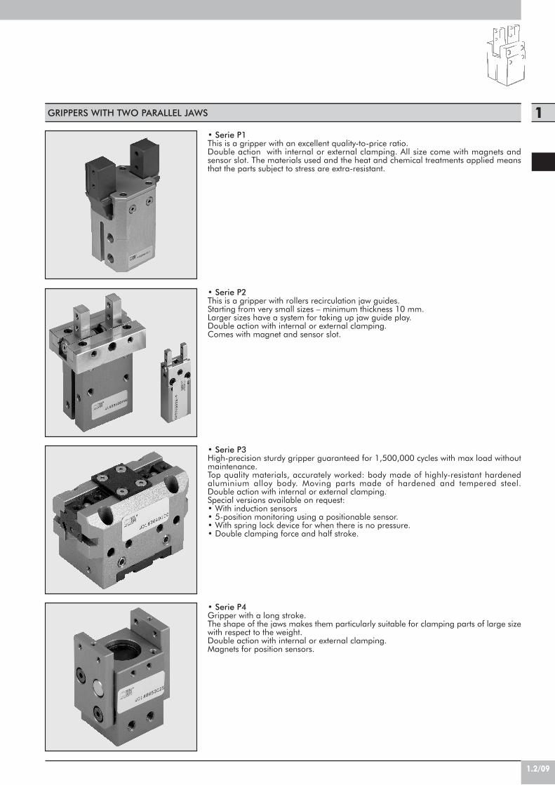
1.2/09
1GRIPPERS WITH TWO PARALLEL JAWS
• Serie P1This is a gripper with an excellent quality-to-price ratio.Double action with internal or external clamping. All size come with magnets andsensor slot. The materials used and the heat and chemical treatments applied meansthat the parts subject to stress are extra-resistant.
• Serie P2This is a gripper with rollers recirculation jaw guides.Starting from very small sizes – minimum thickness 10 mm.Larger sizes have a system for taking up jaw guide play.Double action with internal or external clamping.Comes with magnet and sensor slot.
• Serie P3High-precision sturdy gripper guaranteed for 1,500,000 cycles with max load withoutmaintenance.Top quality materials, accurately worked: body made of highly-resistant hardenedaluminium alloy body. Moving parts made of hardened and tempered steel.Double action with internal or external clamping.Special versions available on request:• With induction sensors• 5-position monitoring using a positionable sensor.• With spring lock device for when there is no pressure.• Double clamping force and half stroke.
• Serie P4Gripper with a long stroke.The shape of the jaws makes them particularly suitable for clamping parts of large sizewith respect to the weight.Double action with internal or external clamping.Magnets for position sensors.

1.2/10
GRIPPERS WITH TWO HINGED JAWS
• Serie P7This is a double-acting gripper with an excellent quality-to-price ratio. Designed forapplication of a retracting magnetic sensor. The body is in a single piece.Simplified jaw replacement method.Provided with magnets and sensor slots.
• Serie P8Single-acting normally open grippers. Virtually all the component parts are made oftechnopolymer to make the device lighter. The smallest version is really tiny – it weighsa mere 36 g.
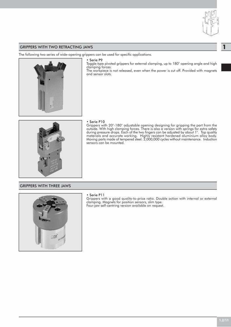
1.2/11
1GRIPPERS WITH TWO RETRACTING JAWS
GRIPPERS WITH THREE JAWS
• Serie P9Toggle-type pivoted grippers for external clamping, up to 180° opening angle and highclamping forces.The workpiece is not released, even when the power is cut off. Provided with magnetsand sensor slots.
• Serie P10Grippers with 20°-180° adjustable opening designing for gripping the part from theoutside. With high clamping forces. There is also a version with springs for extra safetyduring pressure drops. Each of the two fingers can be adjusted by about 1°. Top qualitymaterials and accurate working. Highly resistant hardened aluminium alloy body.Moving parts made of tempered steel. 2,000,000 cycles without maintenance. Inductionsensors can be mounted.
• Serie P11Grippers with a good quality-to-price ratio. Double action with internal or externalclamping. Magnets for position sensors, slim type.Four-jaw self-centring version available on request.
The following two series of wide-opening grippers can be used for specific applications.

GRIPPER WITH 2 PARALLEL JAWSSERIES P1
DIMENSIONS OF GRIPPERS P1-20 ORDERING CODES
CodeW1550200001
DescriptionGRIPPER WITH 2 PARALLEL JAWSP1-20
1.2/12
• Dual-acting parallel gripper for internal and external clamping.
• Anodized aluminium alloy body and tempered steel jaws.• Bottom or side fixing.• All sizes come with magnets and sensor slots.
P1-20 P1-32
NBR2-8 bar (0.2 - 0.8 Mpa)
5÷70Filter lubricated or lubricated air.
Lubrication, if used, must be continuous.20 - 32
180 4205 6.5
0.50 0.70
TECHNICAL DATAGasketsOperating pressureTemperature range °CFluid
Bores mmClamping force (at 6 bar) 20 mm from the top surface NSingle jaw stroke mmWeight Kg
22 H7
1.5
M5 (open)
M6
M5 (close)
N°4 x M4depth 8
N°4 x M4depth 7.5
8
16.5
25
69
18
18
23closed
2225
39
7
12G
6
18
35
14 14
21
39
33 open
85.5
8

1.2/13
1
34 H7
18
M4
N°4 x M5depth 8
M5 (close)
M5 (open)
N°4 x M5depth 7.5
15 G6
25
105.
5
2.2
11.7
6
78
48 32.5
2232.5
48
31close 2020
25
38.5
9
27.5
20
41open
20
DIMENSIONS OF GRIPPERS P1-32 ORDERING CODES
CodeW1550320001
DescriptionGRIPPER WITH 2 PARALLEL JAWSP1-32
ACCESSORIES: MAGNETIC SENSORS
See page 1.2/28 for wiring diagram.
RETRACTABLE SENSOR WITH INSERTION FROM ABOVE
DescriptionHALL N.O. SENSOR, VERTICAL INSERTION 2.5mHALL N.O. SENSOR, VERTICAL INSERTION 300 mm M8REED N.O. SENSOR, VERTICAL INSERTION 2.5mREED N.O. SENSOR, VERTICAL INSERTION 300 mm M8HALL N.O. SENSOR, VERTICAL INSERTION 2m ATEX
CodeW0952025390W0952029394W0952022180W0952028184W0952125556
NOTES

1.2/14
Min./max. operating pressure barTemperature range °CMaximum operating frequency cycles/sFluidSizeBore mmSingle jaw stroke mmClosing force at 6 bar NOpening force at 6 bar NWeight Kg
TECHNICAL FEATURES P2 - 6 P2 - 10 P2 - 16 P2 - 20 P2- 25
1.5 - 75 - 60
220 µm dried or lubricated filtered air. Lubrication, if used, must be continous
6 10 16 20 256 12 16 20 252 2 3 5 7
5.3 28 83 97 1807.4 35 95 115 210
0.027 0.048 0.12 0.24 0.45
4 4
8 close
N°4 x M2depth 4
N°4 M2
N°2 x M3throught
M3 air port (close)
M3 air port(open)
ø7 +0.10
4.8
7
22
10 7
20
5
53
39.5
13.5
24.5
12open
7
18.6
2.5
12
1.5
4.4
GRIPPERS WITH 2 PARALLELROLLER-RECIRCULATION JAWSSERIES P2
These are grippers with 2 parallel jaws with a roller-recirculation guiding system. Double-acting system withclamping in both directions. All the grippers come withmagnet and sensor slots.
DIMENSIONS OF GRIPPER P2-6
CodeW1570060200
DescriptionGRIPPER WITH 2 PARALLEL JAWS P2-6 (For sensor see W0950044180 or W0950045390 page 1.2/24)
ORDERING CODES

1.2/15
1
9.5 open5.5 close
N°2 x ø3depth 3
+ 0.02- 0
N°4 M2.5
N°2 x M3depth 6
N°2 x M3depth 5.5
N°2 x M3depth 5
M3 air port(close)
M3 air port(open)
23
529.7
574
37.5
26.5
3
5.7
27
11.5
1.5
18
23
16
4
15.6
10
18
8
ø12 +0.10
1216 12
N°2 x M4depth 7
+0.02-0
N°2 x M4depth 8
N°2 x M4depth 8
14.5 open6.5 close
N°2 x Ø4depth 4
N°4 M3
M5 air port(close)
M5 air port(open)
1.5
ø17 +0.10
1522
8
4
24 16
30
42.2
7
8
19.5
21.6
13
42.5
15
67.5
31
39
22
5 5
22.5
CodeW1570160200
DescriptionGRIPPER WITH 2 PARALLEL JAWS P2-16 (For sensor see W0950044180 or W0950045390 page 1.2/24)
ORDERING CODES
DIMENSIONS OF GRIPPER P2-16
DIMENSIONS OF GRIPPER P2-10
CodeW1570100200
DescriptionGRIPPER WITH 2 PARALLEL JAWS P2-10 (For sensor see W0950044180 or W0950045390 page 1.2/24)
ORDERING CODES
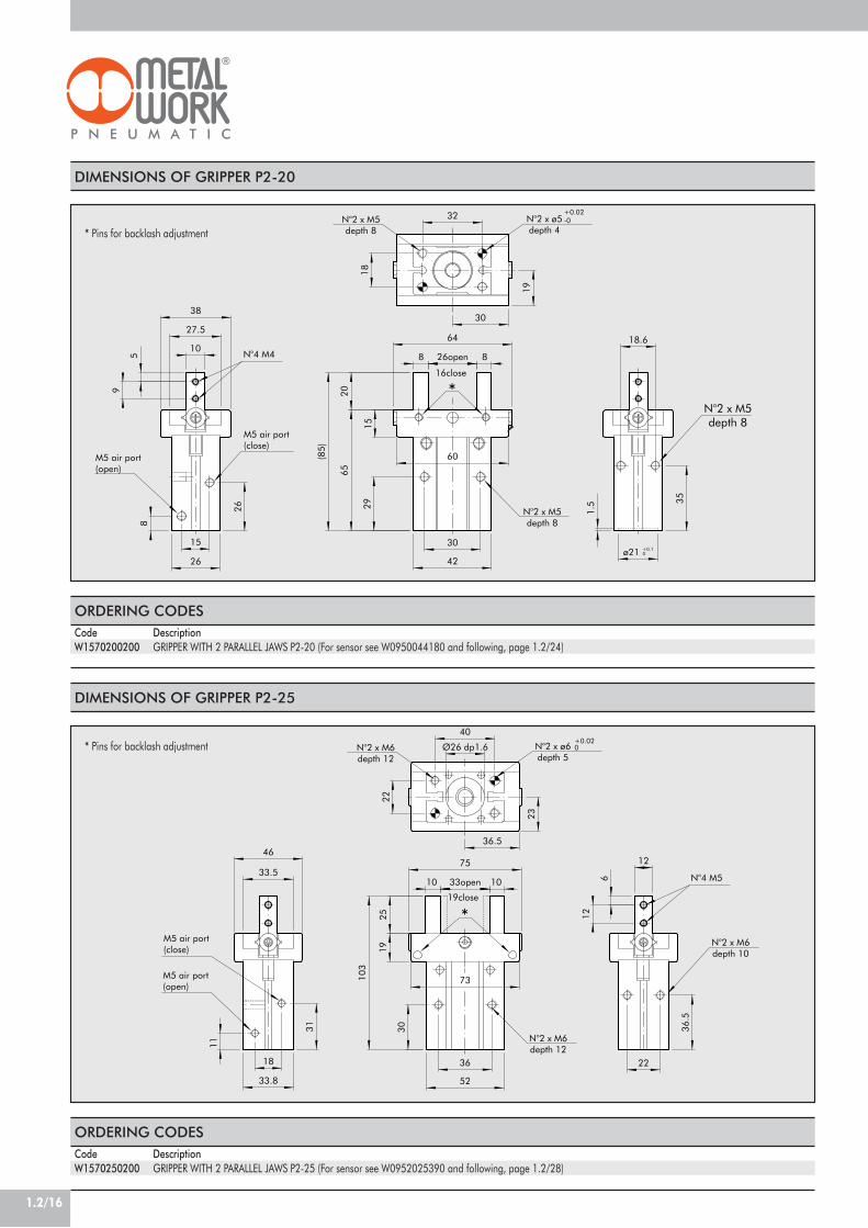
1.2/16
16close
*
+0.02-0
N°2 x M5depth 8
N°2 x M5depth 8
N°2 x M5depth 8
N°4 M4
N°2 x ø5depth 4
M5 air port(close)
M5 air port(open)
158
64
826open
42
32
18
19
30
85
9
27.5
38
15
26
6520
29 35
30
18.6
1.5
10
ø21 +0.10
(85)
60
26
+0.020
N°2 x M6depth 12
N°2 x M6depth 10
19close
N°2 x M6depth 12
N°4 M5
N°2 x ø6depth 5
M5 air port(close)
M5 air port(open)
*
75
103
23
36
52
33open 10
22
36.5
12
10
31
122519
633.5
46
11
Ø26 dp1.6
40
36.5
30
18
33.8
22
73
* Pins for backlash adjustment
CodeW1570250200
DescriptionGRIPPER WITH 2 PARALLEL JAWS P2-25 (For sensor see W0952025390 and following, page 1.2/28)
ORDERING CODES
DIMENSIONS OF GRIPPER P2-25
DIMENSIONS OF GRIPPER P2-20
CodeW1570200200
DescriptionGRIPPER WITH 2 PARALLEL JAWS P2-20 (For sensor see W0950044180 and following, page 1.2/24)
ORDERING CODES
* Pins for backlash adjustment

1.2/17
1
P (N
)
L (mm)0 2525 25 100 15050
320
40
0
600
640
680
720
760
800
120
840
160
200
240
280
80
P3 - 125
P3 - 100
P3 - 50
P3 - 64
P3 - 80
CLAMPING FORCE ACCORDING TO FINGER LENGTH
These are grippers with 2 parallel double-acting jaws withinternal and external clamping. The grippers are guaranteedfor a minimum operation of 1.5 million cycles.Body made of hardened aluminium alloy, jaws made ofground, hardened and tempered steel.Air can be supplied from below or from the side. Varioustypes of fixing are available. The supply includes sensorhaolders (if necessary), fixing screws for all directions andO-rings for direct pneumatic connection.(the inductive sensors are not supplied by MetalWork)
GRIPPER WITH 2 PARALLEL JAWSSERIES P3
Pressure range barTemperature range °CFluidLifeJaw force mmClamping force per jaw at 6 bar NApplicable weight (recommended) KgAir consumption per cycle cm3
Opening time secClosing time secWeight of grippers KgMoment of inertia Kg cm2
Repeatability mmMaximum length of clamping fingers mm
TECHNICAL FEATURES P3 - 50 P3 - 64 P3 - 80 P3 - 100 P3 - 125
2 to 85°C to 85°C
20 m dried or lubricated filtered air. Lubrication, if used, must be continousover 1.5 million cycles
4 6 8 10 650 (L=20mm) 110 (L=20mm) 180 (L=25mm) 225 (L=32mm) 750 (L=32mm)
0.5 1.2 1.8 2.8 8.55 10 20 40 70
0.02 0.02 0.03 0.05 0.080.02 0.02 0.03 0.05 0.08
0.125 0.27 0.43 0.75 1.30.5 1.2 2 10 21
0.01 0.01 0.01 0.01 0.0250 64 80 100 125
GRIPPERP3 - 50P3 - 64P3 - 80P3 - 100P3 - 125
F! (N)250450600800900
Mx (Nm)10309095100
My (Nm)1025354570
Mz (Nm)1215304560
L (mm)2020253232
P (N)50110180225750
Mx MzMy
PFa
L

1.2/18
CodeW1560640200
DescriptionGRIPPER WITH 2 PARALLEL JAWS P3-64
ORDERING CODES
A
A
Vista da "B"
H7
O-Ring ø3x1
min
Adaptor Gripper
H7
m6Sez. A-A
N° 2 x ø3depth 5
H7
N° 2 x M5
H7
M3 (Open)
±0.
2
M3 (Closed)
±0.02 for ø3
"B" M5 (Closed) M5 (Open)
+0
-0.1
±0.02
*
3.5
8
0.5
5
123
18
ø5 M3
ø3
12
31
13.5
6
N° 4 x M4N° 2 x ø3
ø6
9ø3.4
5
20
0.6
8 ø6
N° 2 x ø45.5
5
914.5
50
28 7.622
24
35
13
7
N° 4 x M3
2
4 (stroke)
30
18.5
42
14
35
25.2
24
64
DIMENSIONS OF GRIPPERS P3-64
DIMENSIONS OF GRIPPERS P3-50
A
A
±0.2
M3 depth 5(Closed)
M3 depth 5(Open)
M5 depth 6(Closed)
±0.02 for ø 4 H7
-0.2
+0
+0
-0.1
±0.
1Vista da "B"
N° 2 x ø4depth 4
H7
H7
depth 6
depth 4
N° 2 x M5
±0.
02
N° 2 x ø4
Sez. A-A
H7 min.
N° 4 x M5
O-Ring ø3x1
Adaptor Gripper
m6"B"
*M5 depth 6
(Open)
ø8
52
42
28
N° 4 x M4
20
2.5
42
64
1017
82736
28
20
36
6
ø4.5
10.2
2
18
13
12
2
18
10.2
4
195
4
2113
ø5 M3
ø3
0.5
N° 2 x ø4
ø7.66 (stroke)
38
23
10
CodeW1560500200
DescriptionGRIPPER WITH 2 PARALLEL JAWS P3-50
ORDERING CODES
View from B
View from B
* inductive sensor Ø4
* inductive sensor M8x1

1.2/19
1
CodeW1561000200
DescriptionGRIPPER WITH 2 PARALLEL JAWS P3-100
ORDERING CODES
±0.02 for ø4H7
H7
H7
N° 2 x M5depth 6 N° 4 x M5
H7
M4 depth 5(Open)
M4 depth 5(Closed)
"B"H7
M5 depth 6(Closed)
N° 2 x ø4depth 6
N° 2 x ø4depth 6
min.
Adaptor Gripper
O-Ring ø4x1.5
Sez. A-A
Vista da "B"
m6
±0.02 for ø4
*
M5 depth 6(Open)
5 16 ±0.1
ø4
20±
0.1
8 (stroke)
42+
0-0
.2
45+
0-0
.1
20±
0.2
M4
1
2
36
ø5.1
16
ø7
25
32
12.2
9
52
80
24
52
40
31
48
22
10
ø9
2.5
ø7.6
14
6
12.2
5
25
3
9
N° 4 x M5N° 2 x ø5
69
64
DIMENSIONS OF GRIPPERS P3-100
DIMENSIONS OF GRIPPERS P3-80
CodeW1560800200
DescriptionGRIPPER WITH 2 PARALLEL JAWS P3-80
ORDERING CODES
A
A
*
Vista da "B"
O-Ring ø4x1.5
Adaptor Gripper
+0
-0.2
M5 depth 5(Open)
M5 depth 5(Closed)
H7±0.02 for ø5
H7 min.
±0.1
N° 4 x M6
+0
G1/8" depth 7(Open)
G1/8" depth 7(Closed)
-0.1
±0.
02
H7N° 2 x ø5depth 6
N° 2 x M5depth 6
Sez. A-A
H7
±0.
1
N° 2 x ø5depth 6
±0.02
"B"
m6
35
54
90
ø7
10 (stroke)
28
1
ø4 M5
50
66
44
13
38 14
100
8 30
66 20
32
25
ø6.6
19
N° 4 x M6
48
12
3
51
14.2
2
25
ø9.1
ø11
192.
5
25
80
66
50N° 2 x ø6
14
View from B
View from B
* inductive sensor Ø6.5
* inductive sensor Ø6.5

1.2/20
A
A
M5 depth 5(Open)
M5 depth 5(Closed)
H7
+0
+0
G1/8" depth 7(Open)
G1/8" depth 7(Closed)
N° 4 x M8
-0.1
N° 2 x ø6depth 8
±0.
02
H7
N° 2 x M5depth 6
Sez. A-A
H7
±0.
1
*
N° 2 x ø6depth 8
±0.02
"B"
±0.02 for ø6
-0.2
m6
H7 min.
±0.1Vista da "B"
Adaptor Gripper
O-Ring ø4x1.5
111
62
40
15
36
3.5
60
100
N° 4 x M6
61
21
ø9
82
30
2
16.2
45
14
82
56
125
ø11
3
ø15
30
28
60
N° 2 x ø66 (stroke)
8
248
40
8.5
16.2
38
0.2 min.
ø7
1
ø4 M5
32
59
12
DIMENSIONS OF GRIPPERS P3-125
CodeW1561250200
DescriptionGRIPPER WITH 2 PARALLEL JAWS P3-125
ORDERING CODES
View from B
ACCESSORIESINDUCTION SENSOR FOR P3-50
DescriptionINDUCTION SENSOR Ø 4 mm PNP-NO-2 m
CodeW0950037391
* inductive sensor M8x1

1.2/21
1
dept
h 4
dept
h 4
-0+0.
1
N°2 x M4depth 6
N°4 x M4depth 6
N°4 x M4
M5
(ope
n)M
5(c
lose
)
1Ø3
+0.
020
ø19
3+
0.02
0
22 26
36 c
lose
13 36
6
1022 17
8
4046
46 o
pen
1528 15 38
154 1236
DIMENSIONS OF GRIPPER P4-10
These are grippers with 2 parallel long-stroke jaws. Themechanical design makes them suitable for clamping bulkyparts. All grippers, except for the smallest ones, can mounta retracting magnetic proximity sensor.
GRIPPERS WITH 2 PARALLELLONG-STROKE JAWS – SERIES P4
TECHNICAL FEATURES P4 - 10 P4 - 12 P4 - 16 P4 - 25 P4 - 30
CodeW1580100200
DescriptionGRIPPER WITH 2 LONG-STROKE JAWS P4-10
ORDERING CODES
3 - 75 - 60
1Lubricated or unlubricated filtered air; if used, it must be continuous
2x10 2x12 2x16 2x30 2x305 10 15 30 60
28 41 75 260 26028 41 75 260 260
0.18 0.3 0.5 2.95 3.7
Min./max. operating pressure barTemperature range °CMaximum operating frequency cycles/sFluidBore mmSingle jaw stroke mmClosing force at 6 bar NOpening force at 6 bar NWeight kg

1.2/22
ø12
+0.05
0
ø25 +0.050
dept
h 3
depth
2.5
depth 4
N°2x2 M4through
N°4 x M4depth 6
N°2 x M4depth 5M5 air port
(open)
M5 air port(close)
6
18
44 c
lose
1010 8
7
8
3250
20
10
4
1813
46
19
12
124018
10
484
64 o
pen
22
32
44
3+
0.02
0
22
7
30
29.5
22
1
30
ø16
+0.05
0
ø30 +0.050
N°2 x M5depth 5
deep 2
N°2x2 M5through
N°4 x M5depth 6
dp.3
deep 4
deep
3
M5 air port(open)
M5 air port(close)
54 c
lose
12 10
355
84 o
pen
12 10
5825
382415
1914
44
15
6
14
12
38 28
5 20
5020
5
27
38
1
36
3+
0.02
0
7
ø3+
0.02
0
36
25
DIMENSIONS OF GRIPPER P4-12
DIMENSIONS OF GRIPPER P4-16
ORDERING CODESCodeW1580120200
DescriptionGRIPPER WITH 2 LONG-STROKE JAWS P4-12
ORDERING CODESCodeW1580160200
DescriptionGRIPPER WITH 2 LONG-STROKE JAWS P4-16

1.2/23
1
ø30+0.1
0
ø5 +0.030
N°2x2 M8through
deep 5
deep 5depth 5 N°2x4 M8
depth 9
G1/8 air port(close)
G1/8 air port(open)
50
66
100 close
72
1544
6
15
25
35
105
160 open
24
3690
23 12
3.5
43.5
7
24
82
30
40
3518.5
12.5
72
3.5
5 +0.030
10
49 29
Ø32 +0.10
ø4.7
deep 5
N°4 x M8depth 9
N°2 M8x1.25through
G1/8 air port(close)
N°4 x M8depth 9
G1/8 air port(open)
deep 8.6
22
44
102
5 +0.020
90
15
6624
15
1
25
44
65
36
ø5 +0.020
102
28
1223
105
36
35
40
10
12.5
65
6
18.5
250 open
24
130 close
24
72
80
28
32 +0.10
DIMENSIONS OF GRIPPER P4-25
DIMENSIONS OF GRIPPER P4-30
ORDERING CODESCodeW1580250200
DescriptionGRIPPER WITH 2 LONG-STROKE JAWS P4-25
ORDERING CODESCodeW1580300200
DescriptionGRIPPER WITH 2 LONG-STROKE JAWS P4-30

1.2/24
ACCESSORIES
RETRACTABLE SENSOR WITH INSERTION FROM ABOVE FOR P4-12÷30
DescriptionHALL N.O. SENSOR, VERTICAL INSERTION 2.5mHALL N.O. SENSOR, VERTICAL INSERTION 300 mm M8REED N.O. SENSOR, VERTICAL INSERTION 2.5mREED N.O. SENSOR, VERTICAL INSERTION 300 mm M8HALL N.O. SENSOR, VERTICAL INSERTION 2m ATEX
CodeW0952025390W0952029394W0952022180W0952028184W0952125556
SENSOR FOR P4-10
DescriptionSensor REED 2 wires 24 VDC 1mSensor HALL 3 wires 24 VDC 2m
CodeW0950044180W0950045390
N.B.: for technical data of sensor, see pag. 1.2/28
black
HALL EFFECT+
+
brown
blue
PNP
blue
black
-
brown
34
1
M8
WIRING DIAGRAM FOR W0950045390 TECHNICAL DATA
SwitchTension in DC VTension in AC VCurrent at 25°C APower (ohmic load) WOn time µsOff time µsOn point GaussOff point GaussElectric life (pulses)On voltage drop VNominal operating point GaussOperating frequency HzPolarity reversal protectionShort-circuit protectionDegree of protection (EN 60529)Temperature range °CSensor capsule materialLED displayWiring NO.
Effetto HallPNP
6÷30---0,2
max 60,80,33025
109<1
30÷50max 200
YesNO
IP 67-10 ÷ +70
PA (+G)Yellow
3

1.2/26
18°
7° 3
0'
N° 4 M4
N° 4 x M4depth 8N° 4 x M4depth 8
N° 4 x M4depth 8
M5 (Open)
M5 (Closed)
H7
15
23
28
10.521.5
6
20
16.5188 g7
54
24
3423
19
1
76.5
104
8-0
.05
-0.2
5
DIMENSIONS OF GRIPPERS P7-16
Hinged grippers with 30° opening angle.Bores 16, 20, 32 and 50 mm.All grippers are magnetic with slots in the body with retractingsensors.
GRIPPERS WITH 2 HINGEDJAWS – SERIES P7
Clamping force at 6 barWeight kgOperating pressure barFluidTemperature rangeMaterials
TECHNICAL FEATURES P7 - 16 P7 - 20 P7 - 32 P7 - 50
30N (L*=15 mm) 55N (L*=15 mm) 105N (L*=25 mm) 225N (L*=30mm)0.12 0.19 0.5 1.6
1.5÷10 2÷10 2÷10 1÷10Lubricated or unlubricated filtered air; if used, it must be continuous.
+5°C to 70°C +5°C to 70°C +5°C to 70°C +5°C to 70°CAnodized aluminium body: NBR/polyurethane seal
*L = length of clamping finger
ORDERING CODES
CodeW1590160200
DescriptionGRIPPER WITH2 HINGED JAWS P7-16

1.2/27
1
16.5
12°
N° 4 M4
H7
N° 4 x M4depth 8N° 4 x M4
depth 8
M5 (Open)
M5 (Closed)
8g7
24 18
18
2039
25
25
32 28
18.5
7.2
16.6
2
13
53
75.5
8-0
.05
-0.2
5
104
9°16
°
H7
G1/8 (Open)
G1/8 (Closed)
N° 4 x M5depth 10
N° 4 x M5depth 10
g714
45
32.5
N° 4 x M6
14.5
32.5
75
2.5
28
9.5
110
49
32.5
42
32.5
34
13.522.5
206
12
8° 3
0'8°
30'
22
+0.
1-0
N° 4 x M8depth 12
G1/8 (Closed)
g7
N° 4 x M8
G1/8 (Open)
52
22
76 48
5.5
48
60
5.5N° 2 x M8
71
35
2.5
48
56
11
29 1095
150
206
DIMENSIONS OF GRIPPERS P7-20
DIMENSIONS OF GRIPPERS P7-32
ORDERING CODES
CodeW1590200200
ORDERING CODES
CodeW1590320200
DescriptionGRIPPER WITH2 HINGED JAWS P7-20
DescriptionGRIPPER WITH2 HINGED JAWS P7-32
DIMENSIONS OF GRIPPERS P7-50 ORDERING CODES
CodeW1590500200
DescriptionGRIPPER WITH2 HINGED JAWS P7-50

1.2/28
NOTES
RETRACTABLE SENSOR WITH INSERTION FROM ABOVE
DescriptionHALL N.O. SENSOR, VERTICAL INSERTION 2.5mHALL N.O. SENSOR, VERTICAL INSERTION 300 mm M8REED N.O. SENSOR, VERTICAL INSERTION 2.5mREED N.O. SENSOR, VERTICAL INSERTION 300 mm M8HALL N.O. SENSOR, VERTICAL INSERTION 2m ATEX
CodeW0952025390W0952029394W0952022180W0952028184W0952125556
black
HALL EFFECT+
+
brown
blue
PNP
blue
black
-
blue
brown
brown
34
1
REED EFFECT +
+-
brown
3blue 4
1
M8
M8
WIRING DIAGRAM TECHNICAL DATA
Type of contactSwitchSupply voltage (Ub) VPower WVoltage variationVoltage drop VInput current mAOutput current mASwitching frequency HzShort-circuit protectionOver-voltage suppressionPolarity inversion protectionEMCLED displayMagnetic sensitivityRepeatabilityDegree of protection (EN 60529)Vibration and shock resistanceTemperature range °CSensor capsule material2.5m/2m connecting cableConnecting cable with M8x1Wire NO.
Reed Effetto Hall Effetto HallN.O. N.O. N.O.
- PNP PNP10 ÷ 30 AC/DC 10 ÷ 30 DC 18 ÷ 30 DC3 (peak valve=6) 3 ! 1.7
- ! 10% di Ub ! 10% di Ub- ! 2 ! 2.2- ! 10 ! 10
! 100 ! 100 ! 70! 400 ! 5000 1000
- Yes Yes- Yes Yes- Yes Yes
EN 60 947-5-2 EN 60 947-5-2 EN 60 947-5-2Yellow Yellow Yellow
2,8 mT ±25% 2,8 mT ±25% 2.6! 0,1 mT ! 0,1 mT ! 0,1 (Ub and ta fixed)
IP 67 IP 67 IP 68, IP 69K30 g, 11 ms, 10÷55 Hz, 1mm 30 g, 11 ms, 10÷55 Hz, 1mm 30 g, 11 ms, 10÷55 Hz, 1mm -25 ÷+75 -25 ÷ +75 -20 ÷ +45
PA66 + PA6I/6T PA66 + PA6I/6T PAPVC; 2 x 0,12 mm2 PVC; 3 x 0,14 mm2 PVC; 3 x 0,12 mm2
Polyurethane; 2 x 0,14 mm2 Polyurethane; 3 x 0,14 mm2 -2 3 3
ATEX

1.2/29
1
TABLE OF MOMENTS
Single-acting hinged grippers, normally open, made entirelyof technopolymer. Three sizes with clamping force 25-80N at 6 bar.This solution makes the entire system lighter.This gripper is corrosion-resistant and antimagnetic. Itcomes complete with spring-loaded bracket for pre-loadingthe piece (force 1.5-6 N) and sensor holders.
TECHNOPOLYMER HINGED GRIPPERSSERIES P8
Pressure range barTemperature range °CFluidLifeJaw opening angleClamping force per jaw at 6 bar NApplicable weight (recommended) kgAir consumption per cycle cm3
Opening time secClosing time secWeight of grippers gMoment of inertia kg cm2
Repeatability mm
TECHNICAL FEATURES P8 - 32 P8 - 40 P8 - 50
4 to 75°C to 60°C
20!m dried or lubricated filtered airover 2 million cycles
8° 8° 8°22.5 48 800.2 0.4 0.80.5 1 1.8
0.04 0.05 0.050.06 0.08 0.0836 45 60
0.04 0.12 0.150.1 0.1 0.1
My
Mz
P
Mx
Fa
L
GripperP8 - 32P8 - 40P8 - 50
FA (N)358
Mx (Ncm)92349
My (Ncm)102030
Mz (Ncm)102040
P (N)22.547.580

1.2/30
max 0.5 Nm
min
. 0.5
7
DIMENSIONS OF GRIPPERS P8-32
DIMENSIONS OF GRIPPERS P8-40
2°
8°
*
**
+0-0.1
M3 (Closed)
stro
ke
N° 4 x ø3.4
2.5
ø4
ø3.4
8
ø3.2
65
ø4.1
24
8.4
14.4
20
12.8
17.5
19.2
3225
10.416
~22
4
6.4
5.5
17.6
22.4 4.8
20 1632
3.2
2°
8°
M5 (Closed)
*
**
+0-0.1
N° 4 x ø3.4
H12N° 2 x ø3
stro
ke
2.5
21.5
24
ø4
ø3.4
5
25
16
20
ø4.1
5.5
55
403318
ø3.4
~20
522
40
10.5
28
8
6
25 20
10
30
4
ORDERING CODES
CodeW0710010002
* Removable part clamping system** Induction sensor
DIMENSIONS OF GRIPPERS P8-50
2°
8°
M5 (Closed)
*
**
+0-0.1N° 2 x ø4
N° 4 x ø4.4
H12
stro
ke
~18
27.5
6.2
7
ø4
ø3.4
2541
27.5
ø4.2
3.4
37.5
7.535
50
10
13
31
5.2
12.5
ø4.1
66
20
30
25
31
22.5
50
5
max 0.5 Nm
min
. 0.5
7
ORDERING CODES
CodeW0710010003
* Removable part clamping system** Induction sensor
max 1 Nm
min
. 0.5
10
ORDERING CODES
CodeW0710010004
* Removable part clamping system** Induction sensor
DescriptionTECNOPOLIMER HINGED GRIPPERSP8-32
DescriptionTECNOPOLIMER HINGED GRIPPERSP8-40
DescrizioneTECNOPOLIMER HINGED GRIPPERSP8-50

1.2/31
1INDUCTION SENSOR ORDERING CODES
CodeW0950037391
DescriptionINDUCTION SENSOR Ø 4 mm PNP-NO-2 m
NOTES

1.2/32
ø34 H7
90°
openingadjustement
N°4 x M5depth 10
N°2+2 M6through
N°4 x M5depth 8
G1/8 (close)
G1/8 (open)
120
4936.5
2
18 g6
32.5
32.5
40
26
108
37
54
14
3
54
312
42
12
125
101.
5
32.5
32.5
49
GRIPPER 180° WITH 2 HINGEDJAWS SERIES P9
• Toggle-type pivoted grippers, with adjustable opening angle.
• High clamping forces.• Body made of hard anodized aluminium, jaws and
moving parts made of tempered steel.• Bottom or side fixing.• All sizes come with magnets and sensor slots.
TECHNICAL DATA
DIMENSIONS OF GRIPPERS P9-32
GasketsOperating pressureTemperature range °CFluid
Bores mmJaw opening angleClamping force (at 6 bar), 20 mm from the jaw pivot NWeight Kg
ORDERING CODES
CodeW1530320180
DescriptionHINGED GRIPPER P9-32
P9-32 P9-40
NBR, POLYURETHANE2-8 bar (0.2 - 0.8 Mpa)
5÷70Filter lubricated or lubricated air.
Lubrication, if used, must be continuous.32 - 40
Adjustable 180°180 3000.85 1.5
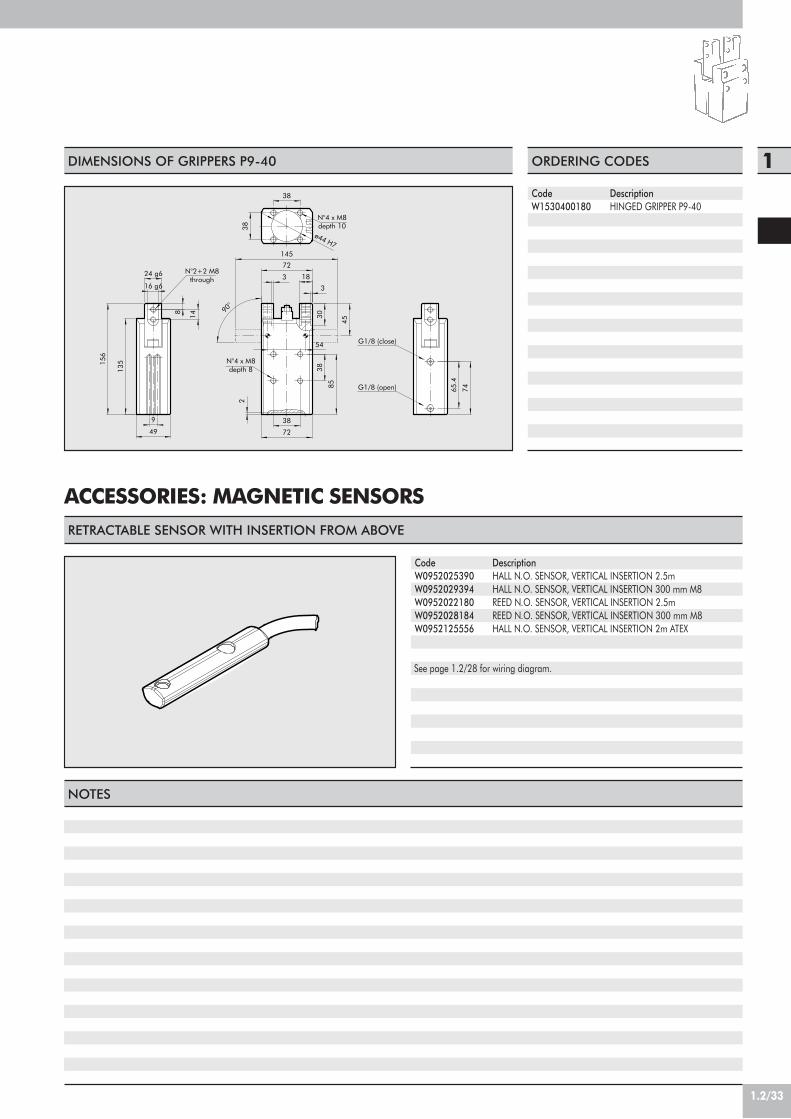
1.2/33
1
ø44 H7
90°
N°4 x M8depth 8
N°4 x M8depth 10
G1/8 (open)
G1/8 (close)
N°2+2 M8through
24 g6
38
38
16 g6
49
18
30
72
38
3
54
145
45
85
38
3
72
65.4
2
74
9
156
135
14
8
DIMENSIONS OF GRIPPERS P9-40 ORDERING CODES
CodeW1530400180
DescriptionHINGED GRIPPER P9-40
ACCESSORIES: MAGNETIC SENSORS
NOTES
See page 1.2/28 for wiring diagram.
RETRACTABLE SENSOR WITH INSERTION FROM ABOVE
DescriptionHALL N.O. SENSOR, VERTICAL INSERTION 2.5mHALL N.O. SENSOR, VERTICAL INSERTION 300 mm M8REED N.O. SENSOR, VERTICAL INSERTION 2.5mREED N.O. SENSOR, VERTICAL INSERTION 300 mm M8HALL N.O. SENSOR, VERTICAL INSERTION 2m ATEX
CodeW0952025390W0952029394W0952022180W0952028184W0952125556
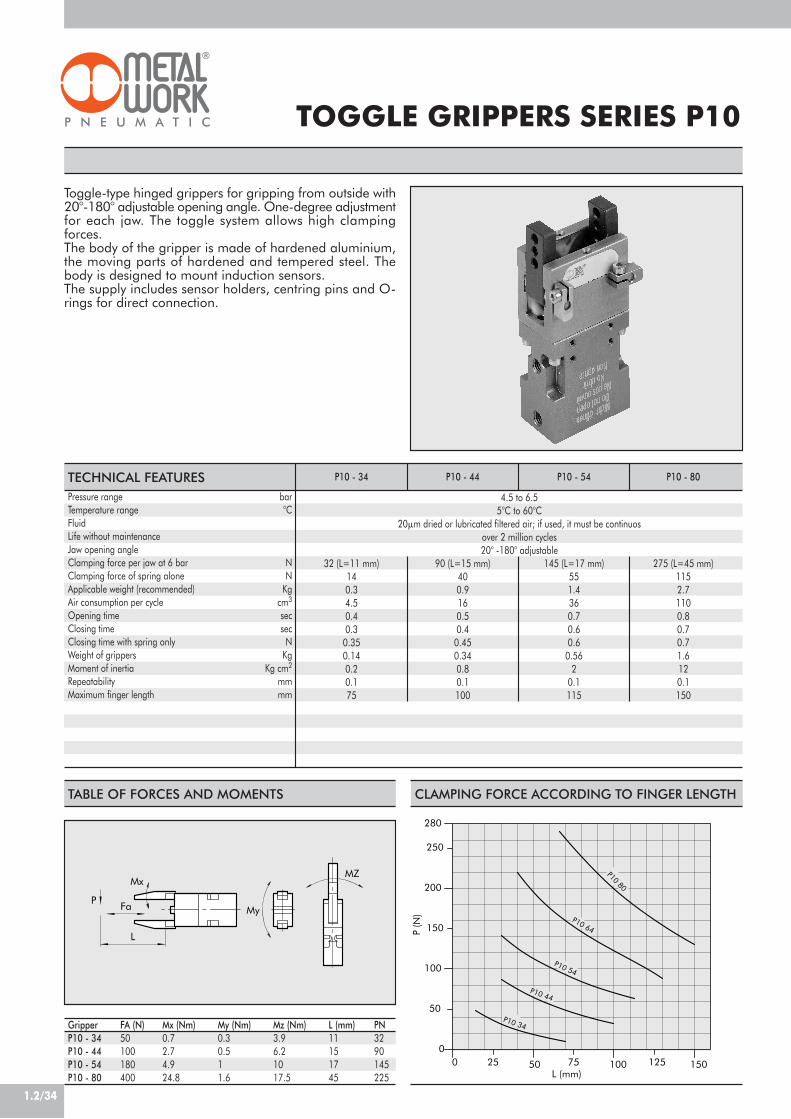
1.2/34
TABLE OF FORCES AND MOMENTS
Toggle-type hinged grippers for gripping from outside with20°-180° adjustable opening angle. One-degree adjustmentfor each jaw. The toggle system allows high clampingforces.The body of the gripper is made of hardened aluminium,the moving parts of hardened and tempered steel. Thebody is designed to mount induction sensors.The supply includes sensor holders, centring pins and O-rings for direct connection.
TOGGLE GRIPPERS SERIES P10
Pressure range barTemperature range °CFluidLife without maintenanceJaw opening angleClamping force per jaw at 6 bar NClamping force of spring alone NApplicable weight (recommended) KgAir consumption per cycle cm3
Opening time secClosing time secClosing time with spring only NWeight of grippers KgMoment of inertia Kg cm2
Repeatability mmMaximum finger length mm
TECHNICAL FEATURES P10 - 34 P10 - 44 P10 - 54 P10 - 80
4.5 to 6.55°C to 60°C
20!m dried or lubricated filtered air; if used, it must be continuosover 2 million cycles20° -180° adjustable
32 (L=11 mm) 90 (L=15 mm) 145 (L=17 mm) 275 (L=45 mm)14 40 55 1150.3 0.9 1.4 2.74.5 16 36 1100.4 0.5 0.7 0.80.3 0.4 0.6 0.7
0.35 0.45 0.6 0.70.14 0.34 0.56 1.60.2 0.8 2 120.1 0.1 0.1 0.175 100 115 150
Mx
My
MZ
P Fa
L
GripperP10 - 34P10 - 44P10 - 54P10 - 80
FA (N)50100180400
Mx (Nm)0.72.74.924.8
My (Nm)0.30.511.6
Mz (Nm)3.96.21017.5
L (mm)11151745
PN3290145225
CLAMPING FORCE ACCORDING TO FINGER LENGTH
50
25 75 125
250
150
280
00
100
200
50L (mm)
100 150
P (N
)
P10 80
P10 34
P10 44
P10 54
P10 64

1.2/35
1
M3 (Closed)
g6
M5 (Closed)
±0.2
N° 2 x ø4.5
ø4H7
*
N° 4 x M4 depth 9
M3(Open)
M3 (Closed)±0.2
H7
O-Ring ø3x1.5
Adaptor Gripper
±0.
2
M3 (Open)
H7ø3 depth 3
4.5
N° 2 x M4depth 8
M5 (Open)N° 2 x ø3depth 3
H7
ø20 depth 2
10
26
30.5
18
12
30
35
255
10
4
6
5
12 15
14
125 1681
38
30
2818
15
M3
1.2
ø6 ø3
44
2
M3(Closed)
M3(Open)
ø3
N° 2 x ø3depth 3
H7
H7
±0.
2
M3(Closed)
N° 2 x ø3.4
H7
±0.2
ø3 depth 3H7
M3(Open)
g6
10 depth 1.5
O-Ring ø3x1.5
±0.2
Adaptor Gripper
N° 6 x M4 depth 6
M5 (Closed)
M5 (Open)
*
665
.5
4
30.5
10
22
28
20
17
3
12 20
34
22
10
7.5
8 7.5
4
ø3ø6
1.2M
3
22
22
10
1611
9
7
5
6
DIMENSIONS OF GRIPPERS P10-34 ORDERING CODES
CodeW1590340201
DIMENSIONS OF GRIPPERS P10-44 ORDERING CODES
CodeW1590440201
DescriptionTOGGLE GRIPPERSP10-34
DescriptionTOGGLE GRIPPERSP10-44
*INDUCTION SENSOR
*INDUCTION SENSOR

1.2/36
ø5 depth 7
M3 (Open)
N° 8 x M5 depth 10H7
ø5
±0.2
*
H7
M3 (Closed)
H7ø20 depth 2.5
M3 (Open)
N° 2 x ø5.5g6
H7±0.2 for ø5
N° 2 x ø5 depth 7
H7
M3 (Closed)
O-Ring ø3x1.5
Adaptor Gripper
M5 (Closed)
M5 (Open)
5
15
13.5
40
20
35
54
14
6
5
24
19 12
10 165
96
18
44
16
34
35
31
40
13
16
1.2
ø6 ø3 M3
4
315
ø8 ø4.2
10
DIMENSIONS OF GRIPPERS P10-54 ORDERING CODES
CodeW1590540201
H7N° 4 x M6 depth 12ø 30 depth 2.5
M3 (Closed)
N° 2 x ø6 depth 7
M3 (Open)
H7
O-Ring ø3x1.5
Adaptor
for ø3
ø3 depth 3
H7
±0.2
Gripper
±0.2
g6
N° 4 x M8 depth 16
H7
M3 (Closed)
M3 (Open)
N° 2 x ø6.6
ø6H7
M5 (Open)
M5 (Closed)
*
64
26
10
22
10
8
32
80
ø6 ø3 M3
1.264
130
23
1516
15
50
6
ø6.8
ø11
16
5.5
20
6
22
40
632
46
65
26
45
5030
6
DIMENSIONS OF GRIPPERS P10-80 ORDERING CODES
CodeW1590800201
*INDUCTION SENSOR
*INDUCTION SENSOR
DescriptionTOGGLE GRIPPERSP10-54
DescriptionTOGGLE GRIPPERSP10-80

1.2/37
1INDUCTION SENSOR ORDERING CODES
CodeW0950037391
DescriptionINDUCTION SENSOR Ø 4 mm PNP-NO-2 m
E
C
F
GD
A
A
DIMENSIONS OF CLAMPING FINGER SLOT
GripperP10 - 34P10 - 44P10 - 54P10 - 80
NOTES
A10141720
BH7
10121422
C9141620
D3456
E6910.513
FM3M4M5M6
GH7
3456

1.2/38
Double-acting grippers with three self-centring jaws, internaland external clamping. The body contains slots for mountingretracting magnetic sensors.
GRIPPERS WITH 3 PARALLELJAWS – SERIES P11
Min./max. operating pressure barTemperature rangeFluid °CBore mmSingle jaw stroke mmClosing force at 6 bar NOpening force at 6 bar NWeight kgMaximum operating frequency cycles/s
TECHNICAL FEATURES
NOTES
P11 - 16 P11 - 20 P11 - 25 P11 - 60
1.5÷75÷60
20 m dried and lubricated filtered air. Lubrication, if used, must be continuous.16 20 25 603 4 5 12.5
58 90 150 88065 108 170 1000
0.12 0.21 0.3 2.71.5 1.5 1.5 1.2

1.2/39
1
M5 air port(close)
M5 air port(open)
N°4 x M3depth 6
N°4 x M3depth 6
closeopen
5
11.5
10
2 19
12.5
2
ø40
(ø34
)
ø12
0 -0.0
5
29
52
ø25
2.5
12
7
8
2.5
3220
ø27.
6
DIMENSIONS OF GRIPPER P11-16 ORDERING CODES
CodeW1570160300
7M5 air port
(close)
N°6 x M3depth 6
closeM5 air port
(open)open N°4 x M4
depth 512.5
ø45
17
(ø36
)
2302
56
6
12.5
8
11
14 11
3
22
ø15
0 -0.0
5
29.6
22.5
30
34
DIMENSIONS OF GRIPPER P11-20 ORDERING CODES
CodeW1570200300
2x ø4.2
Ø46
N°6 x M4depth 8 N°4 x M5
depth 6
open 15
close 10
M5 air port(open)
M5 air port(close)
44
31
Ø35
Ø62
3 +0.050
35.6
32 31
3.5
Ø15
0 -0.0
5
44
14
27
(63)
9
16
21
80 -0
.05
10.5
DIMENSIONS OF GRIPPER P11-25 ORDERING CODES
CodeW1570250300
DescriptionGRIPPERS WITH3 PARALLELJAWS P11-16
DescriptionGRIPPERS WITH3 PARALLELJAWS P11-20
DescriptionGRIPPERS WITH3 PARALLELJAWS P11-25
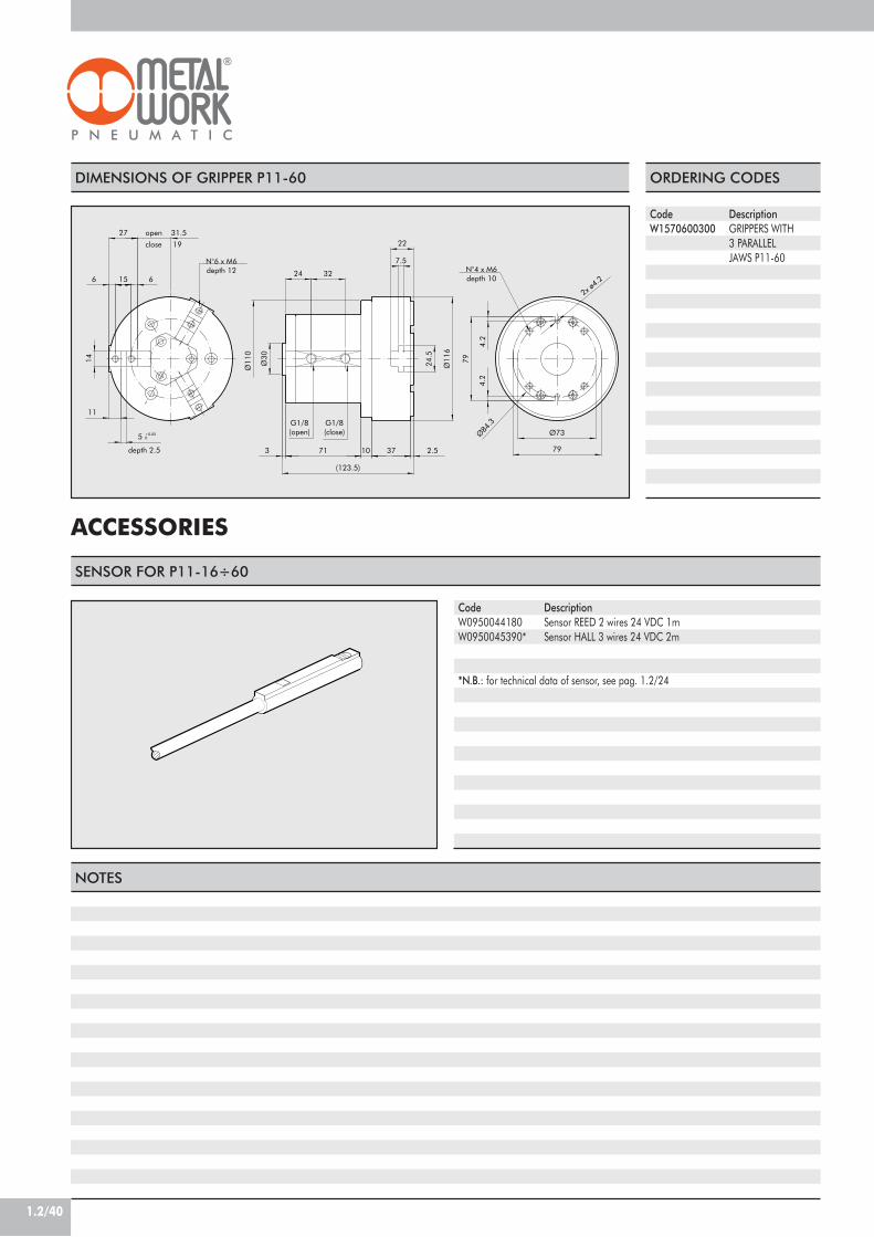
1.2/40
Ø84
.3
2x ø4.2
G1/8(open)
depth 2.5
N°6 x M6depth 12
close 19
N°4 x M6depth 10
open 31.5
G1/8(close)
32
14
27
71
7.5
2.5
24.5
10
Ø11
022
(123.5)
3Ø
116
37
Ø30 79
11
5 +0.050
6
Ø73
4.2
4.2
79
61524
ACCESSORIES
DIMENSIONS OF GRIPPER P11-60 ORDERING CODES
CodeW1570600300
DescriptionGRIPPERS WITH3 PARALLELJAWS P11-60
SENSOR FOR P11-16÷60
DescriptionSensor REED 2 wires 24 VDC 1mSensor HALL 3 wires 24 VDC 2m
CodeW0950044180W0950045390*
*N.B.: for technical data of sensor, see pag. 1.2/24
NOTES

INTRODUCTION
ROTARY ACTUATORS SERIES R1
ROTARY ACTUATORS SERIES R2
ROTARY ACTUATORS SERIES R3
ROTARY ACTUATORS SERIES R3 WITH EXTERNAL SHOCK ABSORBERS
PAGE 1.3/02
PAGE 1.3/06
PAGE 1.3/09
PAGE 1.3/13
PAGE 1.3/18
TABLE OF CONTENTSROTARY ACTUATORS
1.3/01
1
CHAPTER 1.3

1.3/02
ROTARY ACTUATORS
Rotary actuators come in the following types in terms of position:- two positions, fixed or adjustable- three positions, fixed or adjustableRotation is alternating in all the types shown in this catalogue. There also exist rotary actuators that always rotate in the samedirection, with 4, 6, or more positions.
Rotary actuator with single rackA pinion is keyed onto the rotating part and is rotated by means of a rack. The rack isdriven by two pneumatic pistons, one on either side.As there is no play take-up system, it is not suitable for applications requiring accuratepositioning. But there is a version with outer adjustable mechanical stops that stop therotating part and also take up play.
TYPES
NOTES
Rotary actuator with double rackThe pinion keyed onto the rotating element is turned by two opposing racks, each drivenby a pneumatic piston. The system has automatic play take-up, which means it is suitablefor applications requiring accurate positioning. The parallelepiped shape of the designmakes them ideal for use on mechanical arms.
Blade-type rotary actuatorThe rotating element is connected to one or two blades inside a cylindrical chamber.The air pressure on one of the sides of the blade rotates the element. These are compact,cylindrical actuators designed for manipulation where particularly accuracy and highloads are not required.
Chain-type rotary actuatorA chain that is stretched at either end by a pneumatic piston winds round and rotatesa pinion. This type of actuator is not included in our catalogue.
The use of hydraulic decelerators means it is possible to increase absorbed power. Some models in the catalogue have built-indecelerators. For those without, the user can mount decelerators outside the actuator.
With horizontal axis rotation, if the masses are distributed asymmetrically it may be difficult to keep a constant rotation speed usingflow regulators only. In this case it is advisable to use a decelerator.

1.3/03
1RACK-TYPE ROTARY ACTUATORS
Series R1These are rotary actuators with a single rack driven by cylinders inside extruded jacketssimilar to ISO 15552 cylinders. The range includes thrust cylinders with 32 - 100 mmbore.There is a fixed stroke version and one with a mechanically adjustable stroke.Strokes available: 90°, 180°, 270° and 360°.Magnets for standard sensors.The rotating part ends in a shaft or a hole with a spanner slot. This type feature a plainyet sturdy construction and is relatively inexpensive.
Series R2These are actuators with a double rack and play take-up, and have a shaft with aspanner slot.Strokes 90° and 180°. Stroke adjustment using screws. Pneumatic end-of-strokecushioning.Magnets for position sensors.Compact and inexpensive. The smallest size measures a mere 46 x 65 x 28 mm.
Series R3These are actuators with a double rack, play take-up and flange.Strokes available regulation from 0° to 180°.Versions with a mechanical stop or hydraulic end-of-stroke cushioning.Magnets for position sensors.There is a hole in the flange for air pipes or wires.

1.3/04
L per rotazione 180° (mm)
R1R3
R21
10
0.1600
0.5
500
5
50
10 80 10090 200 300 400
100
200
M (N
m)
M
L
BLADE ROTARY ACTUATORS
CALCULATIONS
ROTARY ACTUATOR COMPARATIVE CHART
This catalogue does not include blade-type rotary actuators, but we can supply models with one or two blades on specific request.There are numerous options:- Fixed stroke version: angle of rotation 90°, 180° or 270°.- Adjustable stroke version- Induction sensorsMounting accessories: flange or one or two brackets.
The following needs to be calculated:• Absorbed kinetic energy• Axial forces on the shaft or rotating flange• Radial force on the shaft or rotating flange• Overturning momentThen compare each of the 4 sizes with the admissible ones shown in the catalogue for each rotary actuator. Remember that theapplication of optional hydraulic decelerator, where envisaged, doubles the kinetic energy that can be absorbed by the actuator.
The lines plotted on the graph below show the following for each series of actuators:• Possible torque (at 6 bar)• Length (for actuator with 180° rotation)This allow you to determine the most appropriate series to meet your requirements. For instance, if you want a rotary actuator withtorque greater than 100 N and length less than 300 mm, you can find it in series R3.
L for 180° rotation (mm)

1.3/05
1HOW TO CALCULATE KINETIC ENERGY
MOMENTS OF INERTIA FOR THE MOST COMMON SHAPES
Denomination Unit ofmeasurement Formula Example
SIZING
! Angle of rotation = degrees · ––––––!180 = 90° = –––– rad.!
2
t Rotation time s
= " Ji = 0.078 + 0.02 + 0.133 = 0.232Jta Moment of inertia of rotating massesN.B.: sommare quello delle singole masse Kg m2
Fa
M
Frb
a
Fr Radial force (Remember to take intoaccount centrifugal forces) N (Fc = M · w2 · R) 50
Fa Axial force N 10
M Overturning moment Nm = 50 x 0.1 + 10 x 0 = 5 Nm= M + Fr · a + Fa · b
Unit ofmeasurement Formula Example
M Disk mass
d Disk diameter m
J Moment of inertia of the disk Kg m2
Kg
= ––––Md2
8
d
Disco
0.3
7
= –––––––– = 0.07877 · 0.32
8
M Mass
R Distance between barycenter and rotation axis m
J Moment of inertia of the mass Kg m2
Kg
= MR2
Mass distant fromrotation axis
0.2
0.5
= 0.5 x 0.22 = 0.02
M Mass
L Side of the parallelepiped m
J Moment of inertia of the mass Kg m2
Kg
= M ––––L2
12
Parallelepipedwith barycenteron rotation axis
0.4
10
R
L
= ––––––––– = 0.1310 · 0.42
12
rad
( )2
= 1/2 Jw2 = 1/2 J · –––"t
E Energia cinetica Nm
2
Denomination
= 1/2 · 0.232 · ––––– = 0.57–––
2
!2( )2

ROTARY ACTUATORSSERIES R1, Ø 32-100 mm
1.3/06
Rack-type rotary cylinders in various configurations:• Configuration with standard magnet• Version with male pinion or female hole• Mechanical stroke adjustment• Special configurations on request
The central body has ISO bore holes for wall fixing usingISO pin and/or flange fittings.
NBR10 bar (1 MPa - 145 psi)
–10 to +70Filtered lubricated or unlubricated air.
Lubrication, if used, must be continuous.Ø 32 ; Ø 40 ; Ø 50 ; Ø 63 ; Ø 80 ; Ø 100
90°; 180°; 270°; 360°Extruded profile
Magnetic standard cushioned2500 2800 4500 5600 8500 122004.5 12.5 16 32 70 120
TECHNICAL DATA
COMPONENTS
! ADJUSTING SCREW: steel" HEAD GASKET: NBR# RACK BUSHING: self-lubricating sinteredbronze$ PINION: C40 chromed steel% CENTRAL BODY: anodised aluminium& BALL BEARING' JACKET: aluminium( PISTON GASKET: NBR) PISTON: aluminium* HEAD: die cast aluminium+ NEEDLE: OT 58 brass
10 8 679 2345 1
11
B A
32 40 50 63 80 100
GasketsOperating pressure PTemperature range °CFluid
Bores mmRotation angleType of constructionConfigurationAxial load NMax. moment (6 bar - 0.6 Mpa) MF (Nm)
NB: The product is supplied with negative end-of-stroke piston (in the proximity of head A).The first cycle involves movement of the piston (towards head B) with consequent anti-clockwise rotation of the pinion.
ACTUAL ROTATION ANGLE- Cylinders without regulation of the rotation angle: the manufactural tolerance is -1° +4° compared to the nominal value
- Cylinders with regulation of the rotation angle: the possible regulation counts +/- 3°.
We always suggest to use flow microregulators. Duringthe setup of the actuator, start with CLOSE flowmicroregulators, and open gradually till the achievmentof the required speed.
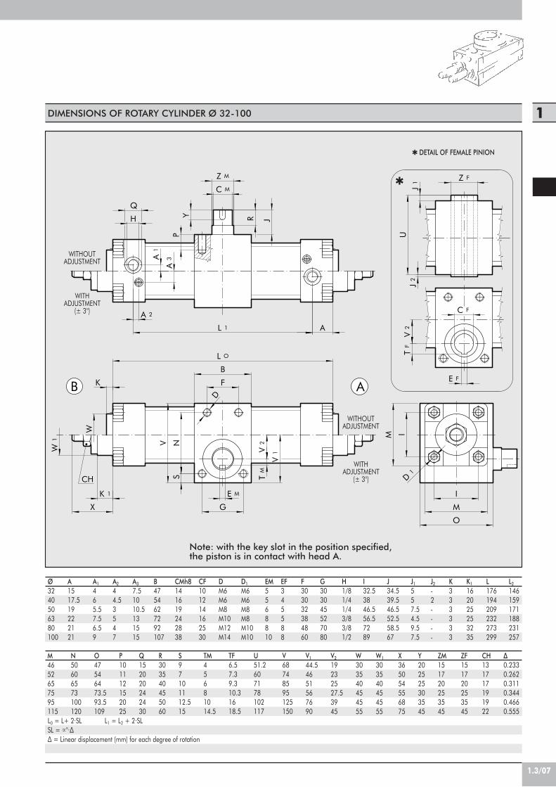
1.3/07
1DIMENSIONS OF ROTARY CYLINDER Ø 32-100
CH
AB
A
D
G
F
K 1
B
N
R
J1
I
I
M
M
O
Y
D1
V
S
W
V2
W1
K
J
X
V2
V1
L O
L 1
Z M
C M
E M
TM
Z F
E F
C F
TF
UJ
2
H
Q
A 2
A1
A3
P
M4652657595115
N50606573100120
O47546473.593.5109
P101112152025
Q152020242430
R303540455060
S97101112.515
TM45681014.5
TF6.57.39.310.31618.5
U51.2607178102117
V68748595125150
V1
44.54651567690
V2
19232527.53945
W303540454555
W1
303540454555
X365054556875
Y202525303545
ZM151720253545
ZF151720253545
CH131717191922
!0.2330.2620.3110.3440.4660.555
L0 = L+ 2·SL L1 = L2 + 2·SLSL = !°·!! = Linear displacement (mm) for each degree of rotation
! DETAIL OF FEMALE PINION
!
WITHOUTADJUSTMENT
WITHADJUSTMENT
(± 3°)
WITHOUTADJUSTMENT
WITHADJUSTMENT
(± 3°)
Ø3240506380100
A1517.519222121
A1
465.57.56.59
A2
44.53547
A3
7.51010.5131515
B4754627292107
CMh8141619242838
CF101214162530
DM6M6M8M10M12M14
D1
M6M6M8M8M10M10
EM5568810
EF345588
F303032384860
G303045527080
H1/81/41/43/83/81/2
I32.53846.556.57289
J34.539.546.552.558.567
J1
557.54.59.57.5
K333333
K1
162025253235
L176194209232273299
L2
146159171188231257
J2
-2----
Note: with the key slot in the position specified,the piston is in contact with head A.

13.2
2.7
18.5
M5
5.9
19.2
14
29.5 29.8
14.8 1.8
20.9
14
M5
20.4
1.6
26M5
20.6
1.7
7.5
14
25.9
47.8
1.3/08
KEY TO CODES
W 1 6 5
W165 cyl. with male pistonW166 cyl. with female pinion
0 5 0
032040050063080100
ANGLE OFROTATION*
0 9 0
090180270360
1
1 cyl. without adjustmentof rotation angle
2 with adjustmentof rotation angle
* expressed in sexagesimal degrees.
ACCESSORIES: MAGNETIC SENSORS
9.1
11.5
25.534
17
ORDERING CODESCodeW0950000201W0950000222W0950000232
DescriptionREED SENSOR ACC. DSM2-C525 HSE.HALL PNP SENSOR ACC. DSM3-N225E.HALL NPN SENSOR ACC. DSM3-M225
SENSOR SUPPORT BRACKETS
Code DescriptionW0950000711 BRACKET ACC. D.32 DST 80
Code DescriptionW0950000712 BRACKET ACC. D.50 DST 81
Code DescriptionW0950000713 BRACKET ACC. D.80-100-125 DST 82
Ø 32÷40 Ø 50÷63 Ø 80÷100

1.3/09
3
2 7 1191213 8 10
1
546 14
1
ROTARY ACTUATOR SERIES R2
Actuator with double rack and play take-up. Four sizes –12, 16, 20 and 25. Two angles of rotation – 90° and 180°.Stroke adjustment system for all sizes. Pneumatic cushioningfor all sizes except the smallest.There are slots in the body to house a magnetic proximitysensor.Air supply, stroke adjustment and cushioning adjustmentare all on the same side.
Pressure range barTemperature range °CAngle adjustment degreesFluidVersionsPortsSizesTheoretical torque (P=pressure in bar) NmMax. axial load NMax. radial load NWeight with 90° rotation KgWeight with 180° rotation KgRotation time without load• 90° angle s• 180° angle s
1.5 to 75 to 60
35° (about +10° -25°)10!m dried or lubricated filtered air. Lubrication, if used, must be continuous
90°/180° rotationBoth at the front
12 16 20 250.065 x P 0.14 x P 0.25 x P 0.48 x P
8 14 40 808 14 40 80
0.18 0.26 0.63 0.80.21 0.31 0.72 1
0.2 0.2 0.2 0.20.3 0.3 0.3 0.3
TECHNICAL FEATURES R2 - 12 R2 - 16 R2 - 20 R2 - 25
COMPONENTS
! ROTARY SHAFT / PINION: hardened and tempered steel" BALL BEARING# FLANGE: anodised aluminium$ PISTON / RACK: hardened and tempered steel% PISTON GASKET: NBR& GUIDE SHOE: PTFE' MAGNET: neodymium( CUSHIONING GASKET: NBR) CUSHIONING PIN: zinc-plated steel* HEAD: anodised aluminium+ PNEUMATIC CONNECTION / STROKE ADJUSTMENT: steel, JACKET: anodised aluminium- BASE: anodised aluminium. SEAL: NBR
We always suggest to use flow microregulators. Duringthe setup of the actuator, start with CLOSE flowmicroregulators, and open gradually till the achievmentof the required speed.

1.3/10
CodeW1620162090W1620162180
DescriptionROTARY ACTUATOR R2-16-90°ROTARY ACTUATOR R2-16-180°
ORDERING CODES
N°4 ø6 depth 3.3 + N°2 M3 ThruN°2 x M5
(Air port)M3
depth 8N°8 M3depth 6
3661(80.5)
46
15
ø80 -0
.02
38
8
20
201
22ø2
8
3+
0.02
0
ø9
2.5
8
37.5
1
17 17
ø28
29(38.5)
76(95.5)
2.5
ROTARY ACTUATOR R2 16 90°/180°
ROTARY ACTUATOR R2 12 90°/180°
M4depth 10
N°2 x M5(Air port)
+0
-0.0
2
+0.
02-0
N°4 ø9.5 depth 5.5 + N°2 M5 Thru
N°8 x M4depth 6
ø9
2.5
33(42)
4
45.5
46 6925
42
64(82)
86(104)
30
22 8
8
1
25 ø34
27.5
21.5
3
ø8
17
ø34
56
10
Dimensions for 180° rotation are given in brackets
CodeW1620122090W1620122180
DescriptionROTARY ACTUATOR R2-12-90°ROTARY ACTUATOR R2-12-180°
ORDERING CODES
Dimensions for 180° rotation are given in brackets

1.3/11
1
CodeW1620252090W1620252180
DescriptionROTARY ACTUATOR R2-25-90°ROTARY ACTUATOR R2-25-180°
ORDERING CODES
N°2 x M5(Air port)
N°8 x M4depth 6
M4depth 10
+0
-0
-0.0
2
+0.
02
N°4 ø11 depth 5.5 + N°2 M6 Thru
69(88)
91(110)
8
22
30
42
8
4
50
2810
1
25
4
ø34
ø9
ø10
ø34
34.5(44)
2.5
4
16
20
64 56 28 77
ROTARY ACTUATOR R2 25 90°/180°
ROTARY ACTUATOR R2 20 90°/180°
2 x M6througth
N°2 x G1/8(Air port)
M5depth 12
N°4 x M5depth 8
78
3.5
ø45
81 (112)
39ø25
89
41.5 (57)
1.5
1
32
45
1.5
1 43
17
5+
0.02
0
40
ø45
10
ø12
0 -0.0
2
ø15
ø15
ø25 66
107 (138)
50 12
26 15
32
42
39
Dimensions for 180° rotation are given in brackets
CodeW1620202090W1620202180
DescriptionROTARY ACTUATOR R2-20-90°ROTARY ACTUATOR R2-20-180°
ORDERING CODES
Dimensions for 180° rotation are given in brackets
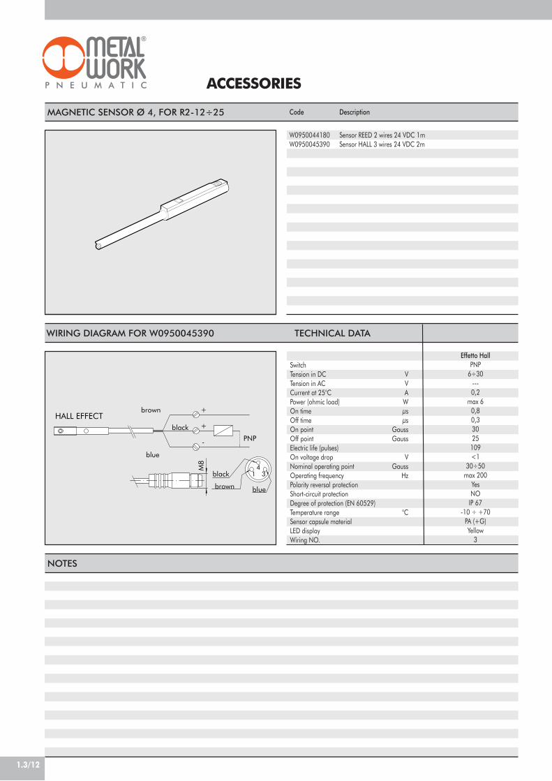
1.3/12
ACCESSORIES
MAGNETIC SENSOR Ø 4, FOR R2-12÷25 Code
W0950044180W0950045390
Description
Sensor REED 2 wires 24 VDC 1mSensor HALL 3 wires 24 VDC 2m
black
HALL EFFECT+
+
brown
blue
PNP
blue
black
-
brown
34
1
M8
WIRING DIAGRAM FOR W0950045390 TECHNICAL DATA
SwitchTension in DC VTension in AC VCurrent at 25°C APower (ohmic load) WOn time µsOff time µsOn point GaussOff point GaussElectric life (pulses)On voltage drop VNominal operating point GaussOperating frequency HzPolarity reversal protectionShort-circuit protectionDegree of protection (EN 60529)Temperature range °CSensor capsule materialLED displayWiring NO.
Effetto HallPNP
6÷30---0,2
max 60,80,33025
109<1
30÷50max 200
YesNO
IP 67-10 ÷ +70
PA (+G)Yellow
3
NOTES

1.3/13
1Actuator with double rack and play take-up.Angle of rotation adjustable from 0 to 180°.The R3 rotary actuator can come with a mechanical stopor hydraulic end-of-stroke cushioning.There is a version with flange and one with shaft (for ø16-20-25-30).There are slots in the body for retracting magnetic proximitysensors, two on each side. There is hole in the flange forair pipes or wires.
COMPONENTS
! ROTARY FLANGE: anodised aluminium" PINION: hardened and tempered steel# BALL BEARING$ PISTON / RACK: hardened and tempered steel% CUSHIONING GASKET: NBR& GUIDE SHOE: PTFE' MAGNET: neodymium( HEAD: anodised aluminium) JACKET: anodised aluminium* SEAL: NBR
VERSIONS:! Stroke adjustment" Stroke adjustment with inside hydraulic shock absorbers
(available from ø25)
Pressure range barTemperature range °CAngle adjustment degreesFluidVersionsSizesBores mmTheoretical torque NmMax. axial load NMax. radial load NWeight KgRotation time without load s
Admissible kinetic energy JouleWITH MECANICAL STOP(with flange W1630__2180 and with shaft W1630__5180)WITH HYDRAULIC DECELERATOR(with flange W1630__2180 and with shaft W1630__5180)
TECHNICAL FEATURES
ROTARY ACTUATORS SERIES R3
R3 - 16 R3 - 20 R3 - 22 R3 - 25 R3 - 30 R3 - 40
3 to 75 to 600-180
20!m dried or lubricated filtered air. Lubrication, if used, must be continuousWith mechanical stop / hydraulic decelerator
16 20 22 25 30 402 x 16 2 x 20 2 x 22 2 x 25 2 x 30 2 x 40
0.9 1.8 2.7 4.6 9.3 2274 135 195 300 340 36078 137 360 450 490 560
0.53 0.99 1.29 2.08 3.9 6.70.2 0.2 0.2 0.2 0.3 0.3
0.007 0.025 0.049 0.082 0.090 0.150
- - - 0.29 1.10 1.60
We always suggest to use flow microregulators. Duringthe setup of the actuator, start with CLOSE flowmicroregulators, and open gradually till the achievmentof the required speed.
10
A
3
51
7
6
2 84 9
B
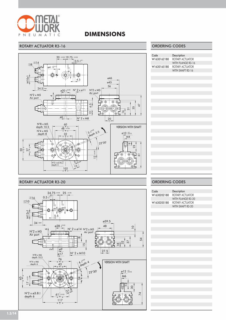
22°30'
depth 4
±0.05
N°8 x M6depth 10.5
+0-0.1N°2 x ø3.8
depth 6
N°4 x M6depth 6
N°2 x M5Air port
N°2 x M5Air port
1016
ø9
1
48
32
10
54
37
6 N° 2 x ø14
24.75
4+0.02
0
5.5
ø5+
0.01
2+
0
18
27.5
61 ±0.05
ø17
15
ø28 +0.050
21.5
34
43
117
2
76
8
N° 2 x M10
25 ±0.05
5+
0.01
2+
0
12
M6
30
ø12 +0-0.018
0.5 +0.10
74
M12
x1
34 MAX
17±
0.05
65
ø59.5
22°30'
N°2 x M5Air port
N°2 x ø2.8depth 5
N°8 x M5depth 10.5
+0-0.1
N°2 x M5Air port
N°4 x M5depth 8
depth 3.5
148
N° 2 x M8
N° 2 x ø11
ø10 +0-0.015
4
6.5
31
ø6
20 ±0.05
12±
0.05
47
35
12
23
61
9
19.75 ±0.05
36
4.5
ø20 +0.050
16
M432
60
2
48 ±0.05
3+0.02
0
15102
0.5 +0.10
4+
0.01
2+
0ø4 +0.012+0
M10
x1
20
ø45
ø46
50 27
24.5 max
1.3/14
DIMENSIONS
ROTARY ACTUATOR R3-16
CodeW1630162180
W1630165180
DescriptionROTARY ACTUATORWITH FLANGE R3-16ROTARY ACTUATORWITH SHAFT R3-16
ORDERING CODES
ROTARY ACTUATOR R3-20
CodeW1630202180
W1630205180
ORDERING CODES
DescriptionROTARY ACTUATORWITH FLANGE R3-20ROTARY ACTUATORWITH SHAFT R3-20
VERSION WITH SHAFT
VERSION WITH SHAFT

22° 30'
22° 30'
N°2 x G1/8Air port
N°2 x M5Air port
18
+0-0.1N°4 x ø3.8
depth 6N°8 x M8depth 12
depth 3
12
12
ø35 +0.05-0
N° 2 x ø18
2
18
38
ø77
ø75
2
61
46
35 ±0.05
N° 2 x M12
10
22
39
66
34.75 ±0.05
5
ø10
26
ø26
6+
0.01
-0
6.5
50±
0.05
100
55
84 ±0.05
80
6 +0.01-0
0.5 +0.10
152
5+
0.02
-0
M14
x1.5
15.5
25
41
M6
94
M14
x1.5
40 MAX
64 MAX
ø16 +0-0,020
1812
M14
x1.5
2564 MAX
22° 30'
+0-0.1ø3.8
6
80
41
M6
94
ø16 +0-0,020
1.3/15
1ROTARY ACTUATOR R3-22
CodeW1630222180
DescriptionROTARY ACTUATORWITH FLANGE R3-22
ORDERING CODES
ROTARY ACTUATOR R3-25
CodeW1630252180
W1630253180
W1630255180
W1630256180
DescriptionROTARY ACTUATORWITH FLANGE R3-25ROTARY ACTUATORWITH FLANGE + SHOCK ABS. R3-25ROTARY ACTUATORWITH SHAFT R3-25ROTARY ACTUATORWITH SHAFT + SHOCK ABS. R3-25
ORDERING CODES
VERSION WITHSHOCK ABSORBERS
VERSIONWITH SHAFT
22°3
0'
N°4 x M6depth 6
N°8 x M6depth 10
dept
h 4
N°2 x M5Air port
N°2 x G1/8Air port
N°2 x ø3.8depth 6
+0-0.1
1018
±0.
05
ø22
ø9
23 2
58.5
8.5
68 ±0.05
N° 2 x M10
N° 2 x ø14
15
4.5
5 +
0.01
2+
0
5.5
30 ±0.05 29.75 ±0.05
0.5 +0.10
ø32 +0.050
5 +
0.01
2+
0
10
40
ø65
32.5
20
49
84
48
24.5
4+
0.02
0
2
127
M12
x1
70
37
18.5
35.5 MAXø68

22°30'
+0-0.1N°4 x ø3.8
depth 6
depth 6
N°4 x M8depth 10
N°2 x M5Air port
18
N°2 x G 1/8Air port
18
N°8 x M8depth 18.5
24
24
0.5 +0.10
6+0.02
-0
40 ±0.0539.75 ±0.05
M20
x1.5
N°2 x M12
8.5
3.5
N°2 x ø17
48
22
ø46 +0.05-0
18
10
ø20
5
58 67
33
2
98
100 ±0.05
31
ø92ø90
75
8+
0.02
-0
ø30
206
8 +0.02-0
64
120
M20
x1.5
90±
0.05
114
16
25
57 MAX
66 MAX
22°30'
16
M6
ø20 +0-0.021
50
113
2
22° 30'
±0.05
N°4 x M8depth 6
±0.05
N°2 x M5Air port
N°2 x G1/8Air port
12
depth 6
12
N°8 x M8depth 15
N°4 x ø3.8depth 6
18
N° 2 x M12
0.5 +0.10
M14
x1.5
35 34.8
N° 2 x ø17.5
73
60
15
50 78
ø16
ø26 16
18
42 43
.5
25
5
ø40 +0.050
3
ø6
+0.
012
+0
6 +
0.01
2+
0
6.5
M6
ø20 +0-0.021
50
100
84 ±0.05
2
10
6 +0.02
0
M14
x1.
568
±
0.05
ø76
ø77
25
183
29
90
16
46.5 MAX
113
64.5 MAX
1812
M14
x1.5
2564 MAX
1.3/16
ROTARY ACTUATOR SERIES R3-30
CodeW1630302180
W1630303180
W1630305180
W1630306180
DescriptionROTARY ACTUATORWITH FLANGE R3-30ROTARY ACTUATORWITH FLANGE + SHOCK ABS. R3-30ROTARY ACTUATORWITH SHAFT R3-30ROTARY ACTUATORWITH SHAFT + SHOCK ABS. R3-30
ORDERING CODES
ROTARY ACTUATOR SERIES R3-40
CodeW1630402180
W1630403180
DescriptionROTARY ACTUATORWITH FLANGE R3-40ROTARY ACTUATORWITH FLANGE + SHOCK ABS. R3-40
ORDERING CODES
VERSION WITHSHOCK ABSORBERS
VERSION WITHSHOCK ABSORBERS
VERSIONWITH SHAFT

1.3/17
1
ACCESSORIES
RETRACTABLE SENSOR WITH INSERTION FROM ABOVE
DescriptionHALL N.O. SENSOR, VERTICAL INSERTION 2.5mHALL N.O. SENSOR, VERTICAL INSERTION 300 mm M8REED N.O. SENSOR, VERTICAL INSERTION 2.5mREED N.O. SENSOR, VERTICAL INSERTION 300 mm M8HALL N.O. SENSOR, VERTICAL INSERTION 2m ATEX
CodeW0952025390W0952029394W0952022180W0952028184W0952125556
This type of sensor can be inserted in the slot of the sensor from above. This means thecylinder heads do not require a through opening.
5.8 500
4.9
BAR FOR GROOVING
Note: the code corresponds to 1 piece
SHOCK ABSORBERS
Code
W0950000160
Description
BAR FOR GROOVING L=500 mm
Description
Shock absorbers SA 0410PD3 SB + nut M14x1.5Shock absorbers PR050 MC2 + nut M20x1.5
Code
09500040080950004005
Bore
ø25-30ø40
SPARES
black
HALL EFFECT+
+
brown
blue
PNP
blue
black
-
blue
brown
brown
34
1
REED EFFECT +
+-
brown
3blue 4
1
M8
M8
WIRING DIAGRAM TECHNICAL DATA
Type of contactSwitchSupply voltage (Ub) VPower WVoltage variationVoltage drop VInput current mAOutput current mASwitching frequency HzShort-circuit protectionOver-voltage suppressionPolarity inversion protectionEMCLED displayMagnetic sensitivityRepeatabilityDegree of protection (EN 60529)Vibration and shock resistanceTemperature range °CSensor capsule material2.5m/2m connecting cableConnecting cable with M8x1Wire NO.
Reed Effetto Hall Effetto HallN.O. N.O. N.O.
- PNP PNP10 ÷ 30 AC/DC 10 ÷ 30 DC 18 ÷ 30 DC3 (peak valve=6) 3 ! 1.7
- ! 10% di Ub ! 10% di Ub- ! 2 ! 2.2- ! 10 ! 10
! 100 ! 100 ! 70! 400 ! 5000 1000
- Yes Yes- Yes Yes- Yes Yes
EN 60 947-5-2 EN 60 947-5-2 EN 60 947-5-2Yellow Yellow Yellow
2,8 mT ±25% 2,8 mT ±25% 2.6! 0,1 mT ! 0,1 mT ! 0,1 (Ub and ta fixed)
IP 67 IP 67 IP 68, IP 69K30 g, 11 ms, 10÷55 Hz, 1mm 30 g, 11 ms, 10÷55 Hz, 1mm 30 g, 11 ms, 10÷55 Hz, 1mm -25 ÷+75 -25 ÷ +75 -20 ÷ +45
PA66 + PA6I/6T PA66 + PA6I/6T PAPVC; 2 x 0,12 mm2 PVC; 3 x 0,14 mm2 PVC; 3 x 0,12 mm2
Polyurethane; 2 x 0,14 mm2 Polyurethane; 3 x 0,14 mm2 -2 3 3
ATEX
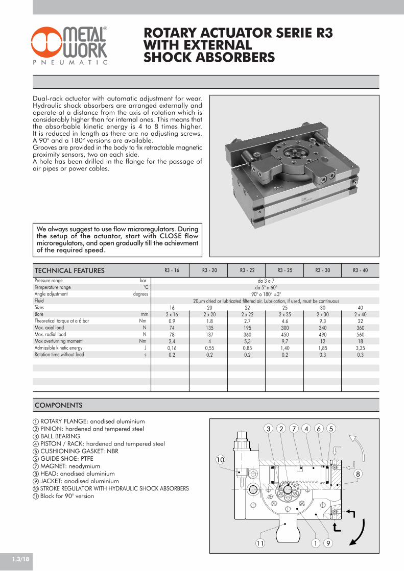
1.3/18
Dual-rack actuator with automatic adjustment for wear.Hydraulic shock absorbers are arranged externally andoperate at a distance from the axis of rotation which isconsiderably higher than for internal ones. This means thatthe absorbable kinetic energy is 4 to 8 times higher.It is reduced in length as there are no adjusting screws.A 90° and a 180° versions are available.Grooves are provided in the body to fix retractable magneticproximity sensors, two on each side.A hole has been drilled in the flange for the passage ofair pipes or power cables.
COMPONENTS
! ROTARY FLANGE: anodised aluminium" PINION: hardened and tempered steel# BALL BEARING$ PISTON / RACK: hardened and tempered steel% CUSHIONING GASKET: NBR& GUIDE SHOE: PTFE' MAGNET: neodymium( HEAD: anodised aluminium) JACKET: anodised aluminium* STROKE REGULATOR WITH HYDRAULIC SHOCK ABSORBERS+ Block for 90° version
7 5
11 9
3 2 4 6
8
1
10
Pressure range barTemperature range °CAngle adjustment degreesFluidSizesBore mmTheoretical torque at a 6 bar NmMax. axial load NMax. radial load NMax overturning moment NmAdmissible kinetic energy JRotation time without load s
TECHNICAL FEATURES
ROTARY ACTUATOR SERIE R3WITH EXTERNALSHOCK ABSORBERS
R3 - 16 R3 - 20 R3 - 22 R3 - 25 R3 - 30 R3 - 40
da 3 a 7da 5° a 60°
90° o 180° ±3°20!m dried or lubricated filtered air. Lubrication, if used, must be continuous
16 20 22 25 30 402 x 16 2 x 20 2 x 22 2 x 25 2 x 30 2 x 40
0.9 1.8 2.7 4.6 9.3 2274 135 195 300 340 36078 137 360 450 490 5602,4 4 5,3 9,7 12 18
0,16 0,55 0,85 1,40 1,85 3,350.2 0.2 0.2 0.2 0.3 0.3
We always suggest to use flow microregulators. Duringthe setup of the actuator, start with CLOSE flowmicroregulators, and open gradually till the achievmentof the required speed.
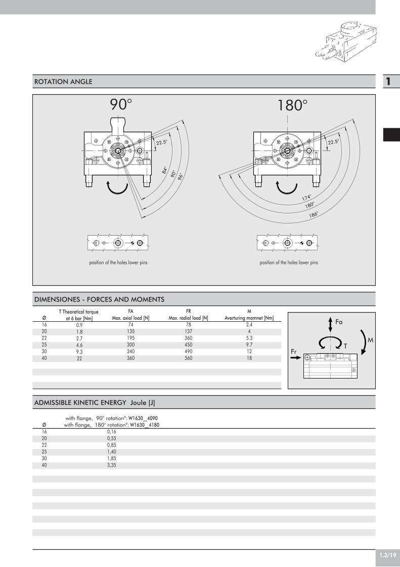
1.3/19
1
84°
22.5°
96°90°
22.5°
180°174°
186°
ROTATION ANGLE
90° 180°
position of the holes lower pins position of the holes lower pins
DIMENSIONES - FORCES AND MOMENTS
Fr
Fa
TM
ADMISSIBLE KINETIC ENERGY Joule [J]
Ø162022253040
with flange, 90° rotation°: W1630__4090with flange, 180° rotation°: W1630__4180
0,160,550,851,401,853,35
T Theoretical torqueat 6 bar [Nm]
0.91.82.74.69.322
FAMax. axial load [N]
74135195300340360
FRMax. radial load [N]
78137360450490560
MAverturing momnet [Nm]
2.44
5.39.71218
Ø162022253040

1.3/20
Sez. A-A
N°2xM5
*
N°2xM5air port
R58.5
N°8xM6
22°3
0'
16
17
N°2xø14
117.0
16.5
8.5
20.5
9.5
M12x1
26
2565122
12
8.5
12
5+
0.01
0
1
18
0.5
15
1454
2
37
ø17
32
4
N°2xM10
6
48ø59.5
101
8
ø43
ø9 passante
ø28 +0.050
24.75 ±0.05
0.5 +0.1025 ±0.05
5 +0.010
57.5
76
Sez. A-A
*
N°2xM5
N°8xM5
22.5°
R50
N°2xM5air port
14
16
60
2.5
36
3
2
4.5
M10x1
N° 2 x M8
9
4
102
4 +0.012-0
20
7
ø18
0.5
ø6 passante
ø20 +0.05-0
6.5
88
N° 2 x ø11
9
ø4512
31
1224
50
6
0.5 +0.1-0
20
20 ±0.05 19.75 ±0.05
35
4+
0.01
2-0
11
47
ø32
105
ROTARY ACTUATOR SERIES R3-20 WITH EXTERNAL SHOCK ABSORBERS, 90/180°
CodeW1630204090
W1630204180
DescriptionROTARY ACTUATOR WITH FLANGE +SHOCK ABSORBERS R3-20-90ROTARY ACTUATOR WITH FLANGE +SHOCK ABSORBERS R3-20-180
ORDERING CODES
CodeW1630164090
W1630164180
DescriptionROTARY ACTUATOR WITH FLANGE +SHOCK ABSORBERS R3-16-90ROTARY ACTUATOR WITH FLANGE +SHOCK ABSORBERS R3-16-180
ORDERING CODES
* Block for 90° version
* Block for 90° version
ROTARY ACTUATOR SERIES R3-16 WITH EXTERNAL SHOCK ABSORBERS, 90/180°

1.3/21
1
A A
Sez. A-A
*
22°30'2
N°2xG1/8
N°2xM5air port
16
R63
N°8xM6
26
2770
17
0.5
6
14
2015
4
ø48
0.5
18.5
8
12
5+
0.01
0
12
4.5
8.5
N°2xM10
11.5
110
49
58
40
32.5
127
N°2xø14 ø65ø67
23
ø32 +0.050
ø9 passante
5 +0.010 29.75 ±0.05
0.5 +0.1030 ±0.05
M12X1
127
62
84
5
A A
Sez. A-A
N°2xG1/8
N°2xM5air port
*
N°8xM8
222°30'
18
R72.5
35 ±0.05
M14X1.5
0.5 +0.10
6 +0.010
ø35 +0.050
34.75 ±0.05
13
ø55
19.5
17
15.515.5
6+
0.01
0
10
ø77
ø75
130
3946
20
66
9
8031
172.
6
61
N°2xø18
10
2.5
33
ø10 passante
ø26
18
N°2xM12
22
5
152
26.5
71
100
ROTARY ACTUATOR SERIES R3-22 WITH EXTERNAL SHOCK ABSORBERS, 90/180°
CodeW1630224090
W1630224180
DescriptionROTARY ACTUATOR WITH FLANGE +SHOCK ABSORBERS R3-22-90ROTARY ACTUATOR WITH FLANGE +SHOCK ABSORBERS R3-22-180
ORDERING CODES
ROTARY ACTUATOR SERIES R3-25 WITH EXTERNAL SHOCK ABSORBERS, 90/180°
CodeW1630254090
W1630254180
DescriptionROTARY ACTUATOR WITH FLANGE +SHOCK ABSORBERS R3-25-90ROTARY ACTUATOR WITH FLANGE +SHOCK ABSORBERS R3-25-180
ORDERING CODES
* Block for 90° version
* Block for 90° version

1.3/22
6
Sez. A-A AA
*
2
22°3
0'
N°2xG1/8
N°2xM5air port
18
R73
N°8xM8
0.5 +0.10
90
8
72
27
6+
0.01
0
19.5
25
17
28
3
2114
ø60
34.75 ±0.05
ø16 passante
29
N°2xø17.5
N°2xM12
1810
33
5
ø76
50
ø77
43.5
78
73
16 16
ø26
35 ±0.05
6 +0.010
183
M14x1.5ø40 +0.05
0
159
130
100
A ASez. A-A
*
22°30'
24
N°2xG1/8
N°2xM5air port
R105
N°8xM8
28 31
15
5867
98
23
20
ø46 +0.05-0
103
206
16
175
39.75 ±0.05
53
113
46
ø20 passante
0.5
2
31
ø92
6
22
N°2xM12
10
ø90
16
N°2xø17
ø30
225
8
ø64
5
75
8 +0.010
40 ±0.05 0.5 +0.10
8+
0.01
0
M20X1.5120
ROTARY ACTUATOR SERIES R3-30 WITH EXTERNAL SHOCK ABSORBERS, 90/180°
CodeW1630304090
W1630304180
DescriptionROTARY ACTUATOR WITH FLANGE +SHOCK ABSORBERS R3-30-90ROTARY ACTUATOR WITH FLANGE +SHOCK ABSORBERS R3-30-180
ORDERING CODES
ROTARY ACTUATOR SERIES R3-40 WITH EXTERNAL SHOCK ABSORBERS, 90/180°
CodeW1630404090
W1630404180
DescriptionROTARY ACTUATOR WITH FLANGE +SHOCK ABSORBERS R3-40-90ROTARY ACTUATOR WITH FLANGE +SHOCK ABSORBERS R3-40-180
ORDERING CODES
* Block for 90° version
* Block for 90° version
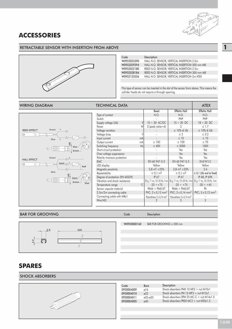
1.3/23
1
SHOCK ABSORBERS
DescriptionShock absorbers PMX 10 MF3 + nut M10x1Shock absorbers PM 15 MF3 + nut M12x1Shock absorbers SPM 25 MC-C + nut M14x1.5Shock absorbers PR50 MC2 + nut M20x1.5
Code0950004009095000401009500040110950004005
Boreø16ø22ø25-ø30ø40
ACCESSORIES
RETRACTABLE SENSOR WITH INSERTION FROM ABOVE
DescriptionHALL N.O. SENSOR, VERTICAL INSERTION 2.5mHALL N.O. SENSOR, VERTICAL INSERTION 300 mm M8REED N.O. SENSOR, VERTICAL INSERTION 2.5mREED N.O. SENSOR, VERTICAL INSERTION 300 mm M8HALL N.O. SENSOR, VERTICAL INSERTION 2m ATEX
CodeW0952025390W0952029394W0952022180W0952028184W0952125556
This type of sensor can be inserted in the slot of the sensor from above. This means thecylinder heads do not require a through opening.
SPARES
5.8 500
4.9
BAR FOR GROOVING
Note: the code corresponds to 1 piece
Code
W0950000160
Description
BAR FOR GROOVING L=500 mm
black
HALL EFFECT+
+
brown
blue
PNP
blue
black
-
blue
brown
brown
34
1
REED EFFECT +
+-
brown
3blue 4
1
M8
M8
WIRING DIAGRAM TECHNICAL DATA
Type of contactSwitchSupply voltage (Ub) VPower WVoltage variationVoltage drop VInput current mAOutput current mASwitching frequency HzShort-circuit protectionOver-voltage suppressionPolarity inversion protectionEMCLED displayMagnetic sensitivityRepeatabilityDegree of protection (EN 60529)Vibration and shock resistanceTemperature range °CSensor capsule material2.5m/2m connecting cableConnecting cable with M8x1Wire NO.
Reed Effetto Hall Effetto HallN.O. N.O. N.O.
- PNP PNP10 ÷ 30 AC/DC 10 ÷ 30 DC 18 ÷ 30 DC3 (peak valve=6) 3 ! 1.7
- ! 10% di Ub ! 10% di Ub- ! 2 ! 2.2- ! 10 ! 10
! 100 ! 100 ! 70! 400 ! 5000 1000
- Yes Yes- Yes Yes- Yes Yes
EN 60 947-5-2 EN 60 947-5-2 EN 60 947-5-2Yellow Yellow Yellow
2,8 mT ±25% 2,8 mT ±25% 2.6! 0,1 mT ! 0,1 mT ! 0,1 (Ub and ta fixed)
IP 67 IP 67 IP 68, IP 69K30 g, 11 ms, 10÷55 Hz, 1mm 30 g, 11 ms, 10÷55 Hz, 1mm 30 g, 11 ms, 10÷55 Hz, 1mm -25 ÷+75 -25 ÷ +75 -20 ÷ +45
PA66 + PA6I/6T PA66 + PA6I/6T PAPVC; 2 x 0,12 mm2 PVC; 3 x 0,14 mm2 PVC; 3 x 0,12 mm2
Polyurethane; 2 x 0,14 mm2 Polyurethane; 3 x 0,14 mm2 -2 3 3
ATEX

INTRODUCTION
COMPACT PRECISION SLIDES SERIES S8
TWIN CYLINDERS SERIES S10
TWIN CYLNDERS SLIDE WITH FIXED BODY SERIES S11
TWIN CYLNDERS SLIDE WITH FIXED PLATES SERIES S12
PRECISION SLIDES SERIES S13
PAGE 1.4/02
PAGE 1.4/08
PAGE 1.4/16
PAGE 1.4/20
PAGE 1.4/26
PAGE 1.4/32
TABLE OF CONTENTSGUIDE UNITS AND SLIDES
1.4/01
1
CHAPTER 1.4

1.4/02
The range of guide units and slides is very extensive.Guides are grouped into families.
GUIDE UNITS AND SLIDESTYPES
Guide units to couple with standard cylindersThese are separate units to which an ISO 6432 or ISO 15552 cylinder is attached.
Pneumatic single piston cylinders with supports at the end of the piston rod.The common factor in all the various configurations is that, as well the calibrated holefor the piston in the cylinder body or front head, there are other slots housing bushesor guide bearings for additional piston rods.
Guides with pneumatic actuatorThe main part of this actuators is the guiding section which determines the shape,applications, loads, maximum strokes and cost. The pneumatic part is housed in oneof the bodies of the unit or it comes as a complete cylinder housed inside the guide.
Twin pneumatic cylinderThe jacket has two calibrated holes for housing two pistons and rods side by side. Thereare versions with a single piston rod, through piston rod and different power suppliesdepending on whether you wish to fix the jacket or the flanges to the ends of the pistonrod.
Rodless cylindersIn these cylinders the piston rod is integral with a carriage on the outside of the jacket,so there is no piston rod. We offer versions in which the jacket is open, with a C-shapedsection, and piston and carriage linked mechanically.

1.4/03
1GUIDE UNITS TO COUPLE WITH STANDARD CYLINDERS
• Series S1GDS, GDH and GDM for ISO 6432 minicylinders and ISO 15552 cylinders.The GDS series, which has a C-shaped body, is for lesser loads. Series GDH and GDMhave an H-shaped body. GDH guide units guide piston rod with ball re-circulationbushes and are more suitable for high speed.There guides for minicylinders with bores 12-25 mm (see catalogue page 1.1/16) andguides for cylinders with bore 32-100 mm (see catalogue page 1.1/85).
• Series S2Short-stroke anti-rotation cylinders.Bores available Ø 12 –100.See catalogue pages 1.1/28 - 1.1/29
• Series S3Twin-rod cylindersThese are cylinders with axial movement and ISO 15552 ports.Bores available Ø 32 –100.See catalogue page 1.1/110.
• Series S4Compact anti-rotation cylindersThese are similar in design to the short-stroke anti-rotation cylinders. They are slightlysturdier since the guide rod diameter is greater in some sizes and the top plate is fixedon better.There are bores Ø 12 –100 with dimensions to UNITOP NFE 49-004 1 and, and boresØ 32-100 with fixing dimensions as for ISO 15552 cylinders.See catalogue pages 1.1/39 - 1.1/40.
CYLINDERS WITH PISTON ROD SUPPORT SYSTEM
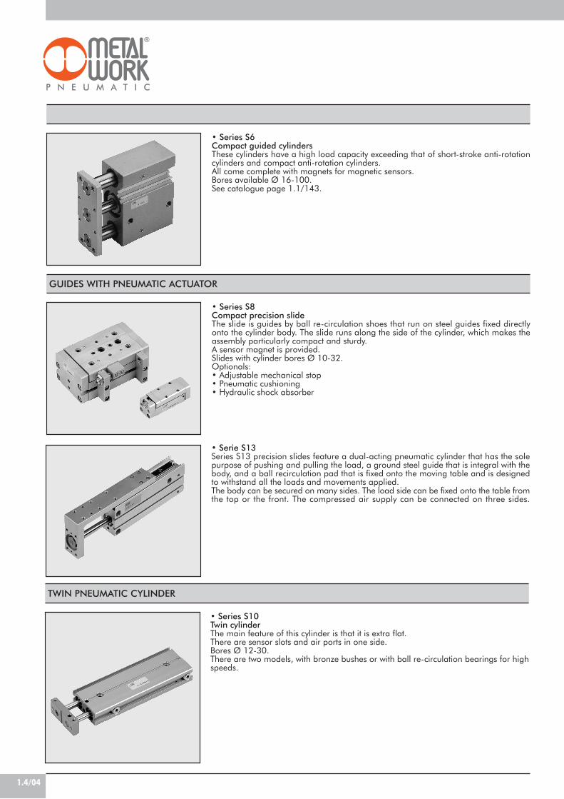
1.4/04
• Series S8Compact precision slideThe slide is guides by ball re-circulation shoes that run on steel guides fixed directlyonto the cylinder body. The slide runs along the side of the cylinder, which makes theassembly particularly compact and sturdy.A sensor magnet is provided.Slides with cylinder bores Ø 10-32.Optionals:• Adjustable mechanical stop• Pneumatic cushioning• Hydraulic shock absorber
GUIDES WITH PNEUMATIC ACTUATOR
• Series S6Compact guided cylindersThese cylinders have a high load capacity exceeding that of short-stroke anti-rotationcylinders and compact anti-rotation cylinders.All come complete with magnets for magnetic sensors.Bores available Ø 16-100.See catalogue page 1.1/143.
• Series S10Twin cylinderThe main feature of this cylinder is that it is extra flat.There are sensor slots and air ports in one side.Bores Ø 12-30.There are two models, with bronze bushes or with ball re-circulation bearings for highspeeds.
TWIN PNEUMATIC CYLINDER
• Serie S13Series S13 precision slides feature a dual-acting pneumatic cylinder that has the solepurpose of pushing and pulling the load, a ground steel guide that is integral with thebody, and a ball recirculation pad that is fixed onto the moving table and is designedto withstand all the loads and movements applied.The body can be secured on many sides. The load side can be fixed onto the table fromthe top or the front. The compressed air supply can be connected on three sides.

1.4/05
1• Series S11Twin cylinder guide unitThe main feature of this guide unit is that it is extra flat.It is similar to the twin cylinder, but has through rods and two flanges at the ends. BoresØ 12-30.Two hydraulic shock absorbers can be mounted optionally.There are two models, with bronze bushes or with ball re-circulation bearings for highspeeds.
• Series S12Twin cylinder slideThis is similar to the twin cylinder guide unit but here it is the central body that moveswhile the two end flanges are fixed. The air ports are at the ends of the piston rods.Two hydraulic shock absorbers can be mounted optionally.Bores Ø 16-30.There are two models, with bronze bushes or with ball re-circulation bearings for highspeeds.
• Series S15Standard rodless cylinderThis is the most compact guide unit available. In all the above models the axial lengthis equal to a basic value plus double the stroke, but here it is equal to the basic valueplus the stroke, so slightly less than half the length of the other models. The other twodimensions are also the basic values, comparable only with solutions adopting pistonrod supporting system. There are, however, limitations regarding radial loads andapplicable moments.Bores Ø 16-25-32-40-63.See catalogue page 1.1/117.
RODLESS CYLINDER
• Series S16Rodless twin cylindersThese have twice the axial force of the standard cylinder. The radial load capacity andtorque resistance are also much greater.Bores Ø 16-32.See catalogue page 1.1/125.

1.4/06
COMPARATIVE CHART – GUIDE UNITS AND SLIDES
• Series S18Rodless cylinder with V-guideTwo V-guides are built into the anodized aluminium liner. A cap with two wear-resistantacetal resin guiding plates run along the guides.Cylinder bores Ø25 and Ø63. Refer to page 1.1/135 of the catalogue.
• Series S17Rodless cylinder with ball recirculating guideFor improved load capacity with respect to standard rodless cylinders, this version hasa steel guide on one side of the jacket and the re-circulation shoes fixed onto the boresØ 16-63 carriage.See catalogue page 1.1/127.
The lines plotted on the graph below show the following for each series of guide or slide:• Maximum radial load F• Stroke SThis allows you to determine the most appropriate series to meet your requirements. For instance, if you want a slide able to withstandradial loads greater than 100 N and with a stroke greater than 100 mm, you can find it in series S15, S16, S17 and S18.
S (mm)40
3000
1000
100
10
500
50
F (N
)
10000
20 6010 50 80 3000100 200 400 600 8001000 5000
S4-S2
S3S8
S1
S10-S11S12
S6
S15S16
S17
5000
S18
S13
S
F

1.4/07
1
aL
F
La
F
a
Fb
a
b
a+stroke
F
F
a
F
3 3/2 a c2
2F(a/b+1)
F(2a/b+1)
LOAD CONDITIONS LOAD OR STROKE EQUIVALENCE
Admitted loads for each guide unit are shown in the catalogue.If the load is not aligned with the moving plate, it is possible to determine the equivalent load or stroke with a goodapproximation.
TO CHECKTHE ADMISSIBLELOAD
TO CHECKTHE ARROW

1.4/08
There are two sliding systems available:• Type SB-B with in-line ball bearings• Type S8-C with ball re-circulation bearingsThe guides fixed onto the slide body are made of hardenedand tempered steel. There are slots in the body of slide S8-C for mounting a retracting sensor. There are also a kitsfor mounting adjustable mechanical stops or hydraulicshock absorbers.All S8 slides come on request with permanent pneumaticcushioning.Slide made with Toss-System.
COMPONENTS FOR SERIES S8-B
! SLIDE BODY: aluminium" GUIDES: high Cr alloy steel# IN-LINE BALL CAGE: steel$ MOVING PART: aluminium% FRONT PLATE: aluminium& PISTON ROD: thick chromium plated steel' BASE: Hostaform®
( PISTON: NBR) AIR PORT PLATE: aluminium* STATIC O-RINGS: NBR+ CUSHIONING CONE: OT 58
10
3
9 68 111 2 5744
Pressure range barTemperature range °CFluidBores mmStrokes mmType of guide
Air portsVersions
End-of-stroke sensors
TECHNICAL DATA2-6
-10 to +6020! unlubricated filtered air. Lubrication, if used, must be continuous
10-16-20-25-32 20-25-3210; 25; 50; 80; 100; 125; 160; 200 25; 50; 80; 100; 125; 160; 200
In-line ball bearings Ball re-circulation(bars of hardened, tempered and ground steel) (bars of hardened, tempered and ground steel)
Both on front plateDouble-acting Double-acting
With permanent pneumatic cushioning With permanent pneumatic cushioningWith 5 mm adjustable mechanical stops
With hydraulic shock absorbersWith pneumatic cushioning and mechanical stops
Magnetic, only on request Magnetic, retracting type
COMPACT PRECISION SLIDESSERIES S8
S8-B S8-C
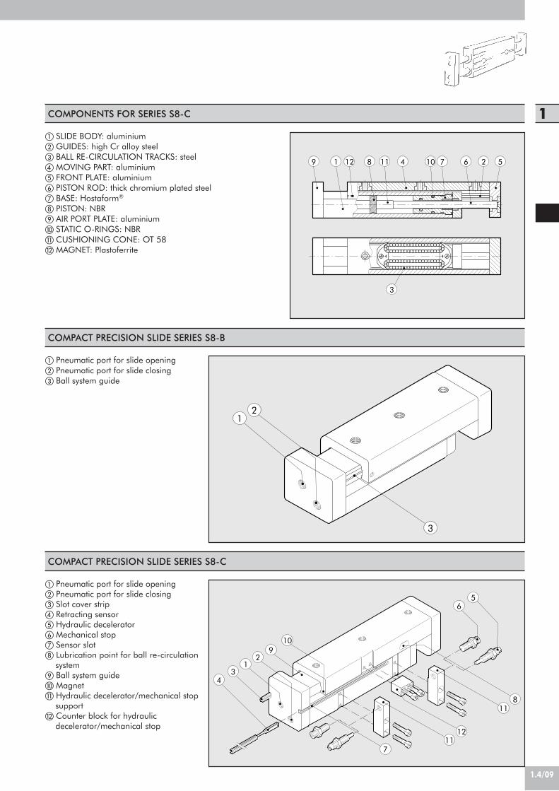
1.4/09
1
! Pneumatic port for slide opening" Pneumatic port for slide closing# Slot cover strip$ Retracting sensor% Hydraulic decelerator& Mechanical stop' Sensor slot( Lubrication point for ball re-circulation
system) Ball system guide* Magnet+ Hydraulic decelerator/mechanical stop
support, Counter block for hydraulic
decelerator/mechanical stop
COMPONENTS FOR SERIES S8-C
! SLIDE BODY: aluminium" GUIDES: high Cr alloy steel# BALL RE-CIRCULATION TRACKS: steel$ MOVING PART: aluminium% FRONT PLATE: aluminium& PISTON ROD: thick chromium plated steel' BASE: Hostaform®
( PISTON: NBR) AIR PORT PLATE: aluminium* STATIC O-RINGS: NBR+ CUSHIONING CONE: OT 58, MAGNET: Plastoferrite
101 2
3
4 5689 712 11
COMPACT PRECISION SLIDE SERIES S8-B
! Pneumatic port for slide opening" Pneumatic port for slide closing# Ball system guide
12
3
COMPACT PRECISION SLIDE SERIES S8-C
10
65
11
1
11
43
29
12
8
7
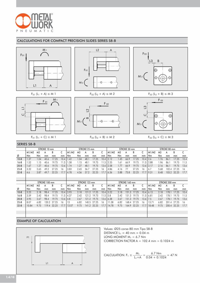
1.4/10
CALCULATIONS FOR COMPACT PRECISION SLIDES SERIES S8-B
F01
1M
AL1
02F
M 2
L2 AF03
M 3
L3 B
01F 1M
L1C
F01 (L1 + A) ! M 1 F02 (L2 + A) ! M 2 F03 (L3 + B) ! M 3
F01 (L1 + C) ! M 1 F02 (L2 + B) ! M 2 F03 (L3 + C) ! M 3
SERIES S8-B
EXAMPLE OF CALCULATION
F1
L1 A
Values: Ø25 corsa 80 mm Tipo S8-BDISTANCE L1 = 40 mm = 0.04 mLONG MOMENT M1 = 6.7 NmCORRECTION FACTOR A = 102.4 mm = 0.1024 m
CALCULATION: F1 ! –––––– = ––––––––––––– = 47 NM1
L1+A6.7 Nm
0.04 + 0.1024
STROKE 10 mm STROKE 25 mm STROKE 50 mm STROKE 80 mm
STROKE 100 mm STROKE 125 mm STROKE 160 mm STROKE 200 mm
F 03
M 3
CL3
02F
M 2
BL2
Ø10-B16-B20-B25-B32-B
M1/M2Nm1.371.521.673.324.6
M3Nm1.041.151.272.653.87
Amm40.640.640.649.249.7
Bmm17.2519.7519.7527.2532.25
Cmm10.411.513.61617.7
M1/M2Nm1.421.581.743.834.78
M3Nm1.041.151.272.654.56
Amm48.148.148.156.757.2
Bmm17.2519.7519.7527.2532.25
Cmm10.411.513.61617.7
M1/M2Nm2.122.352.584.866.36
M3Nm1.451.611.774.165.88
Amm66.966.966.97775.8
Bmm17.2519.7519.7527.2532.25
Cmm10.411.513.61617.7
M1/M2Nm2.62.883.176.79.31
M3Nm1.761.962.165.688.48
Amm86.186.186.1102.4103.2
Bmm17.2519.7519.7527.2532.25
Cmm10.411.513.61617.7
Ø10-B16-B20-B25-B32-B
M1/M2Nm3.233.593.958.0710.84
M3Nm2.182.422.676.829.75
Amm98.498.498.4120.2119.4
Bmm17.2519.7519.7527.2532.25
Cmm10.411.513.61617.7
M1/M2Nm3.934.374.81313.07
M3Nm2.182.422.676.829.75
Amm121.2121.2121.2140.5141.2
Bmm17.2519.7519.7527.2532.25
Cmm10.411.513.61617.7
M1/M2Nm5.225.86.3811.3814.78
M3Nm2.182.422.676.829.75
Amm151.3151.3151.3168.4164.9
Bmm17.2519.7519.7527.2532.25
Cmm10.411.513.61617.7
M1/M2Nm6.136.817.513.7118.48
M3Nm2.182.422.676.829.75
Amm178.1178.1178.1201.4200.4
Bmm17.2519.7519.7527.2532.25
Cmm10.411.513.61617.7
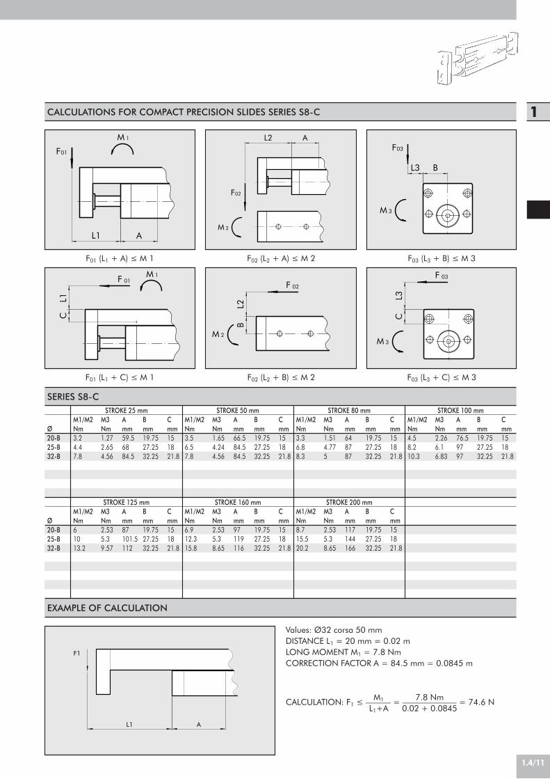
1.4/11
1
EXAMPLE OF CALCULATION
F1
L1 A
Values: Ø32 corsa 50 mmDISTANCE L1 = 20 mm = 0.02 mLONG MOMENT M1 = 7.8 NmCORRECTION FACTOR A = 84.5 mm = 0.0845 m
CALCULATION: F1 ! –––––– = ––––––––––––– = 74.6 NM1
L1+A7.8 Nm
0.02 + 0.0845
CALCULATIONS FOR COMPACT PRECISION SLIDES SERIES S8-C
F01 (L1 + A) ! M 1 F02 (L2 + A) ! M 2 F03 (L3 + B) ! M 3
F01 (L1 + C) ! M 1 F02 (L2 + B) ! M 2 F03 (L3 + C) ! M 3
F01
1M
AL1
02F
M 2
L2 AF03
M 3
L3 B
01F 1M
L1C
F 03
M 3
CL3
02F
M 2
BL2
SERIES S8-C
Ø20-B25-B32-B
M1/M2Nm3.24.47.8
M3Nm1.272.654.56
Amm59.56884.5
Bmm19.7527.2532.25
Cmm151821.8
M1/M2Nm3.56.57.8
M3Nm1.654.244.56
Amm66.584.584.5
Bmm19.7527.2532.25
Cmm151821.8
M1/M2Nm3.36.88.3
M3Nm1.514.775
Amm648787
Bmm19.7527.2532.25
Cmm151821.8
M1/M2Nm4.58.210.3
M3Nm2.266.16.83
Amm76.59797
Bmm19.7527.2532.25
Cmm151821.8
Ø20-B25-B32-B
M1/M2Nm61013.2
M3Nm2.535.39.57
Amm87101.5112
Bmm19.7527.2532.25
Cmm151821.8
M1/M2Nm6.912.315.8
M3Nm2.535.38.65
Amm97119116
Bmm19.7527.2532.25
Cmm151821.8
M1/M2Nm8.715.520.2
M3Nm2.535.38.65
Amm117144166
Bmm19.7527.2532.25
Cmm151821.8
STROKE 25 mm STROKE 50 mm STROKE 80 mm STROKE 100 mm
STROKE 125 mm STROKE 160 mm STROKE 200 mm

1.4/12
Out
In
L3
H1
H2
D2
L5 L5 L6
B2
D4
B1
L1
B3
L2 L4
D3
D1
H4
H3
B4
B5
Bore(mm)10/16
Weight [g]20
Weight [g]25/32
Weight [g]
L 3L 4L 5L 6
L 3L 4L 5L 6
L 3L 4L 5L 6
1080153124190/29080253124390101204527.5640/840
2595302 x 2324240/38095302 x 2324440121406527.5740/1000
50135702 x 4324340/530135702 x 4324580156752 x 5027.51000/1300
801752 x 553 x 4224440/6301752 x 553 x 42247302111302 x 78271340/1740
1002002 x 67.53 x 5024.5540/7302002 x 67.53 x 5024.58302462 x 82.52 x 9527.51540/2040
1252452 x 903 x 6524.5590/8802452 x 903 x 6524.510302862 x 102.53 x 77271840/2400
1603052 x 1203 x 8524.5780/10803052 x 1203 x 8524.512803412 x 1303 x 9527.52200/2840
2003602 x 147.54 x 7823.5890/12803602 x 147.54 x 7823.515304112 x 1653 x 11532.52600/3440
(mm) Stroke
DIMENSIONS OF COMPACT PRECISION SLIDES SERIES S8-B
BoreØ (mm)1016202532
Piston rodbore Ø (mm)5881012
B1(mm)2630303545
B2(mm)3540405565
B3(mm)2530303949
B4(mm)12.013.012.517.520.0
B5(mm)2125.524.534.7540.5
D1
M5M5M5G 1/8”G 1/8”
D2 Thread/Depth (mm)M6/5.5M6/5.5M6/8.0M8/7.5M8/7.5
D3 Thread/Depth (mm)M5/10M6/12M6/14M8/18M8/20
D4 Thread/Depth (mm)M6/11.5M6/11.5M6/11.5M8/10.5M8/10.5
H1(mm)263239.54550
H2(mm)10.512.015.519.020.0
H3(mm)5.07.58.012.010.8
H4(mm)14.015.520.023.028.3
L1(mm)1212121515
L2(mm)2727223535

1.4/13
1
Bore(mm)20
Weight [g]25/32
Weight [g]
L 3L 4L 5L 6
L 3L 4L 5L 6
25135702 x 4324780156/ 21175/1302 x 50/2 x 7827.5/271400/2100
501752 x 553 x 42248602111302 x 78271700/2420
802002 x 67.53 x 5024.59602462 x 82.52 x 9527.52060/2800
1002452 x 903 x 6524.512002862 x 102.53 x 77272440/3260
1253052 x 1203 x 8524.514603412 x 1303 x 9527.52920/3900
1603602 x 147.54 x 7823.517404112 x 1653 x 11532.53585/4760
2004403 x 1254 x 9823.521605013 x 1404 x 11030.04345/5640
(mm) Stroke
DIMENSIONS OF COMPACT PRECISION SLIDES SERIES S8-C
In
Out
B1
H3
H1
D4
H2
B2
B4
D1
H5
D3
L1
L6L5
D2
H6
H4
L3
B5
L5
B3L2 L4
BoreØ (mm)202532
Piston rodbore Ø (mm)81012
B1(mm)283545
B2(mm)405565
B3(mm)303949
B4(mm)12.517.520.0
B5(mm)24.534.7540.5
D1
M5G 1/8”G 1/8”
D2 Thread/Depth (mm)M6/8.0M8/7.5M8/7.5
D3 Thread/Depth (mm)M6/14M8/15M8/20
D4 Thread/Depth (mm)M6/11.5M8/10.5M8/10.5
H1(mm)486070
H2(mm)6.210.210.2
H3(mm)26.235.240.2
H4(mm)8.011.010.8
L1(mm)121515
L2(mm)273535
H5(mm)20.024.028.3

1.4/14
Bore(mm)20
Weight [g]25/32
Weight [g]
L 3L 4L 5L 6
L 3L 4L 5L 6
25135702 x 4324830156/21175/1302 x 50/2 x 7827.5/271500/2200
501752 x 553 x 42249102111302 x 78271800/2520
802002 x 67.53 x 5024.510102462 x 82.52 x 9527.52160/2900
1002452 x 903 x 6524.512502862 x 102.53 x 77272540/3360
1253052 x 1203 x 8524.515103412 x 1303 x 9527.53020/4000
1603602 x 147.54 x 7823.517404112 x 1653 x 11532.53685/4860
2004403 x 1254 x 9823.521605013 x 1404 x 11030.04445/5740
(mm) Stroke
In
Out
H5
B4
H4
D4
B5B2
H2
B1
H3
H1
B6
D1
H6
L5L5 L6
D3L4
B3
L1
L2
L3
D2
L8 max
L7 max
DIMENSIONS OF COMPACT PRECISION SLIDES SERIES S8-C, COMPLETE
BoreØ (mm)202532
Piston rodbore Ø (mm)81012
B1(mm)283545
B2(mm)405565
B3(mm)303949
B4(mm)12.517.520.0
B5(mm)24.534.7540.5
D1
M5G 1/8”G 1/8”
D2 Thread/Depth (mm)M6/8.0M8/7.5M8/7.5
D3 Thread/Depth (mm)M6/14M8/15M8/20
D4 Thread/Depth (mm)M6/11.5M8/10.5M8/10.5
H1(mm)486070
H2(mm)6.210.210.2
H3(mm)26.235.240.2
H4(mm)8.011.010.8
L1(mm)121515
L2(mm)273535
H5(mm)20.024.028.3
B6(mm)172222
L7(mm)555
L8(mm)161616

1.4/15
1
* starting from Ø20 and stroke 80
KEY TO CODES FOR S8-B PRECISION SLIDE
W 1 4 8 B
Precision slideseries S8 type B
TYPE
1 0
1016202532
DIAMETER
O
0 non-magnetic6* non-magnetic, cushioned
fixed, pneumatic
VARIANT
0 5 0
10 mm25 mm50 mm80 mm
100 mm125 mm160 mm200 mm
STROKE
KEY TO CODES FOR S8-C PRECISION SLIDE
W 1 4 8 C
Precision slideseries S8 type C
TYPE
2 0
202532
DIAMETER
O
0 magnetic6* magnetic with
fixed pneum. cushioning7 magnetic with
mechanical stop4 magnetic with
hydraulic shock absorber8* magnetic with mech.
stop and fixed pneum.cushioning
VARIANT
0 5 0
25 mm50 mm80 mm
100 mm125 mm160 mm200 mm
STROKE
* starting from stroke 50
RETRACTABLE SENSOR WITH INSERTION FROM ABOVE
DescriptionHALL N.O. SENSOR, VERTICAL INSERTION 2.5mHALL N.O. SENSOR, VERTICAL INSERTION 300 mm M8REED N.O. SENSOR, VERTICAL INSERTION 2.5mREED N.O. SENSOR, VERTICAL INSERTION 300 mm M8HALL N.O. SENSOR, VERTICAL INSERTION 2m ATEX
CodeW0952025390W0952029394W0952022180W0952028184W0952125556
This type of sensor can be inserted in the slot of the sensor from above. This means thecylinder heads do not require a through opening.
black
HALL EFFECT+
+
brown
blue
PNP
blue
black
-
blue
brown
brown
34
1
REED EFFECT +
+-
brown
3blue 4
1
M8
M8
WIRING DIAGRAM TECHNICAL DATA
Type of contactSwitchSupply voltage (Ub) VPower WVoltage variationVoltage drop VInput current mAOutput current mASwitching frequency HzShort-circuit protectionOver-voltage suppressionPolarity inversion protectionEMCLED displayMagnetic sensitivityRepeatabilityDegree of protection (EN 60529)Vibration and shock resistanceTemperature range °CSensor capsule material2.5m/2m connecting cableConnecting cable with M8x1Wire NO.
Reed Effetto Hall Effetto HallN.O. N.O. N.O.
- PNP PNP10 ÷ 30 AC/DC 10 ÷ 30 DC 18 ÷ 30 DC3 (peak valve=6) 3 ! 1.7
- ! 10% di Ub ! 10% di Ub- ! 2 ! 2.2- ! 10 ! 10
! 100 ! 100 ! 70! 400 ! 5000 1000
- Yes Yes- Yes Yes- Yes Yes
EN 60 947-5-2 EN 60 947-5-2 EN 60 947-5-2Yellow Yellow Yellow
2,8 mT ±25% 2,8 mT ±25% 2.6! 0,1 mT ! 0,1 mT ! 0,1 (Ub and ta fixed)
IP 67 IP 67 IP 68, IP 69K30 g, 11 ms, 10÷55 Hz, 1mm 30 g, 11 ms, 10÷55 Hz, 1mm 30 g, 11 ms, 10÷55 Hz, 1mm -25 ÷+75 -25 ÷ +75 -20 ÷ +45
PA66 + PA6I/6T PA66 + PA6I/6T PAPVC; 2 x 0,12 mm2 PVC; 3 x 0,14 mm2 PVC; 3 x 0,12 mm2
Polyurethane; 2 x 0,14 mm2 Polyurethane; 3 x 0,14 mm2 -2 3 3
ATEX

1.4/16
48 192
10
67 5A
B
34bis
There are two sliding systems available:- on bushes- on ball recirculating bearingsThe frame is made up of two paired cylinders with acommon anodized aluminium body containing slots forretracting sensors.There are 5 bores available:2 x Ø12, 2 x Ø16, 2 x Ø20, 2 x Ø25 and 2 x Ø30
COMPONENTS
! FLANGE: anodized aluminium" REAR BASE: anodized aluminium# BUFFER: rubber$ ADJUSTABLE STRIKER PLATE. Zinc-plated steel$ bis. HYDRAULIC DECELERATOR% FRONT BASE: brass& PISTON: brass' MAGNET: Plastoferrite( CYLINDER BODY: anodized aluminium) STATIC O-RING: NBR* BALL RE-CIRCULATION BUSH
VERSIONS:! With sliding bushes" With ball bushes
TWIN CYLINDER SERIES S10
Pressure range barTemperature range °CFluidPiston speed mm/sVersionsSizesBores mmPiston rod diameter mmStrokes mm
mmmmmm
Weight (C=stroke)Sliding version KgBall bearing version KgTheoretical thrustThrust force (!P = pressure in bar) da NPull force da NMax. loadsSliding version NBall bearing version N
TECHNICAL FEATURES S10-12 S10-16 S10-20 S10-25 S10-30
3 to 75 to +60
20!m dried or lubricated filtered air. Lubrication, if used, must be continuous.30 to 100 mm/s
System with sliding bushes / System with ball bushes available with stop screw or hydraulic decelerator12 16 20 25 30
2 x 12 2 x 16 2 x 20 2 x 25 2 x 306 8 10 12 1615 15 25 25 2525 25 50 50 5050 50 75 75 75– 75 100 100 100– – – 125 125
0.12 + (0.002 x C) 0.24 + (0.0025 x C) 0.51 + (0.005 x C) 0.76 + (0.006 x C) 1.3 + (0.009 x C)0.21 + (0.002 x C) 0.48 + (0.0025 x C) 0.77 + (0.005 x C) 0.18 + (0.006 x C) 1.92 + (0.009 x C)
Multiply the value shown by the pressure in bar2.26 x !P 4 x !P 6.28 x !P 9.8 x !P 14.1 x !P1.69 x !P 3 x !P 4.11 x !P 7.5 x !P 10.1 x !P
(The values shown refer to the min. and max. strokes)3 to 1.5 6 to 3 10 to 3.5 12 to 5.6 20 to 76 to 4 11 to 6 20 to 7 26 to 8 36 to 11

1.4/17
1DIMENSIONS OF TWIN CYLINDER SERIES S10
CodeW1440122...*W1440162...*W1440202...*W1440252...*W1440302...**Enter stroke in mm.
Ø1216202530
U2833404251
V3846566686
W33355
X2026303952
Y1012141719
Z11111
ABM5M6M8M10M12
AGM5M5M5M5G 1/8”
Strokes for bore 12 mmStrokes for bore 16 mmStrokes for bore 20 mmStrokes for bore 25 mmStrokes for bore 30 mm
15; 25; 50;15; 25; 50; 75;25; 50; 75; 100;25; 50; 75; 100; 125;25; 50; 75; 100; 125;
+ = ADD THE STROKE++ = ADD TWICE THE STROKE
Ø 12
for sensor
**=Ø 20,25,30Ø16
V1
VIEW FROM “K”
V1––546482
Ø1216202530
A1822263236
B4656667898
C1016101010
C15062687487
C222222
C360748290105
D45678
E20262932.537.5
F1.51.51.52.52.5
G911131618
H1012141719
L810121416
M4.34.35.56.58.5
N88910.514
P44568
QM3M4M4M5M6
R56778
S88101212
T910111113
E120202931.539.5
Q1H7
44446
R133335
K
**
for sensor
**=Ø 20,25,30Ø16
F
Q depth R(x4) Q1 depth R1(x2)
C3++
M th
ru(x
2)
T U
N d
epth
P(x
4)
A
Z
DAG(x2)
Y
A
B
Q d
epth
S(x
2)
W
V
E C+
C2+ L
Q th
ru(x
2)
V
GH
E1
C1+
X
VB
AB
V1

1.4/18
DIMENSIONS OF TWIN CYLINDER SERIES S10, ON BALL BEARINGS
CodeW1440123...*W1440163...*W1440203...*W1440253...*W1440303...**Enter stroke in mm.
Ø1216202530
U4757697288
V3846566686
W33355
X2026303952
Y1012141719
Z11111
ABM5M6M8M10M12
AGM5M5M5M5G 1/8”
Strokes for bore 12 mmStrokes for bore 16 mmStrokes for bore 20 mmStrokes for bore 25 mmStrokes for bore 30 mm
15; 25; 50;15; 25; 50; 75;25; 50; 75; 100;25; 50; 75; 100; 125;25; 50; 75; 100; 125;
+ = ADD THE STROKE++ = ADD TWICE THE STROKE
K
**
for sensor
**=Ø 20,25,30Ø16
E
LC2+C1+
E1 F
H G
V
Q th
ru(x
2)
T
A
AG(x2)
B
V
M th
ru(x
2)
C3++
N d
epth
P(x
4)
Y
D
A
Q d
epth
S(x
2)
W
U Z
Q1 depth R1(x2)Q depth R(x4)
X BV
C+
AB
V1
Ø 12
for sensor
**=Ø 20,25,30Ø16
V1
VIEW FROM “K”
V1––546482
Ø1216202530
A1822263236
B4656667898
C1010101010
C16990100108124
C222222
C37998111120142
D45678
E29.54246.551.556
F1.51.51.52.52.5
G911131618
H1012141719
L810121416
M4.34.35.56.58.5
N88910.514
P44568
QM3M4M4M5M6
R56778
S88101212
T910111113
E129.53843.546.558
Q1H7
44446
R133335

1.4/19
1
ACCESSORIES
MAGNETIC SENSOR Ø 4, FOR SLIDE S10 Ø12
5.8 500
4.9
BAR FOR GROOVING
DescriptionSensor REED 2 wires 24 VDC 1mSensor HALL 3 wires 24 VDC 2m
CodeW0950044180W0950045390*
* For tecnical data of sensor see page 1.1/24
DescriptionBAR FOR GROOVING L=500 mm
CodeW0950000160
Note: the code corresponds to 1 piece
RETRACTABLE SENSOR WITH INSERTION FROM ABOVE, FOR SLIDE S10 Ø16÷30
DescriptionHALL N.O. SENSOR, VERTICAL INSERTION 2.5mHALL N.O. SENSOR, VERTICAL INSERTION 300 mm M8REED N.O. SENSOR, VERTICAL INSERTION 2.5mREED N.O. SENSOR, VERTICAL INSERTION 300 mm M8HALL N.O. SENSOR, VERTICAL INSERTION 2m ATEX
CodiceW0952025390W0952029394W0952022180W0952028184W0952125556
This type of sensor can be inserted in the slot of the sensor from above. This means thecylinder heads do not require a through opening.
black
HALL EFFECT+
+
brown
blue
PNP
blue
black
-
blue
brown
brown
34
1
REED EFFECT +
+-
brown
3blue 4
1
M8
M8
WIRING DIAGRAM TECHNICAL DATA
Type of contactSwitchSupply voltage (Ub) VPower WVoltage variationVoltage drop VInput current mAOutput current mASwitching frequency HzShort-circuit protectionOver-voltage suppressionPolarity inversion protectionEMCLED displayMagnetic sensitivityRepeatabilityDegree of protection (EN 60529)Vibration and shock resistanceTemperature range °CSensor capsule material2.5m/2m connecting cableConnecting cable with M8x1Wire NO.
Reed Effetto Hall Effetto HallN.O. N.O. N.O.
- PNP PNP10 ÷ 30 AC/DC 10 ÷ 30 DC 18 ÷ 30 DC3 (peak valve=6) 3 ! 1.7
- ! 10% di Ub ! 10% di Ub- ! 2 ! 2.2- ! 10 ! 10
! 100 ! 100 ! 70! 400 ! 5000 1000
- Yes Yes- Yes Yes- Yes Yes
EN 60 947-5-2 EN 60 947-5-2 EN 60 947-5-2Yellow Yellow Yellow
2,8 mT ±25% 2,8 mT ±25% 2.6! 0,1 mT ! 0,1 mT ! 0,1 (Ub and ta fixed)
IP 67 IP 67 IP 68, IP 69K30 g, 11 ms, 10÷55 Hz, 1mm 30 g, 11 ms, 10÷55 Hz, 1mm 30 g, 11 ms, 10÷55 Hz, 1mm -25 ÷+75 -25 ÷ +75 -20 ÷ +45
PA66 + PA6I/6T PA66 + PA6I/6T PAPVC; 2 x 0,12 mm2 PVC; 3 x 0,14 mm2 PVC; 3 x 0,12 mm2
Polyurethane; 2 x 0,14 mm2 Polyurethane; 3 x 0,14 mm2 -2 3 3
ATEX

1.4/20
23489 167 5
10 B
A
Ft
Fp
There are two sliding systems available:• on bushes• on ball bearingsThe frame is made up of two paired through-rod cylinderswith a common anodized aluminium body containing slotsfor retracting sensors.There are 5 bores available:2 x Ø12, 2 x Ø16, 2 x Ø20, 2 x Ø25 and 2 x Ø30.The piston rods are united by means of a plate on whichmechanical stops or hydraulic shock absorbers can bemounted.
TWIN CYLINDER SLIDEWITH FIXED BODY SERIES S11
FluidPressure rangeTemperature range °CPiston speed mm/sVersionsBores mmPiston rod diameter mmStrokes mm
Weight = X + (Y · C) kgC= strokeSliding version
Ball bearing version
Theoretical thrust (P = relative pressure in bar)Max. loadsLoads with sliding version N
Loads with ball bearing version N
TECHNICAL FEATURES20! filtered air
1.5 to 7 bar (0.15 to 0.7 MPa)5 to +6030 to 200
With sliding bushes / With ball bearing bushes / With stop screw / With hydraulic shock absorbers12 16 20 25 306 8 10 12 16
25 25 25 25 2550 60 50 50 5075 75 75 75 75– 100 100 100 100– – 125 125 125– – – 150 150
X = 0.14 X = 0.25 X = 0.5 X = 0.7 X = 1.24Y = 0.002 Y = 0.0035 Y = 0.045 Y 0.007 Y = 0.01X = 0.25 X = 0.37 X = 0.78 X = 1.04 X = 1.98
Y = 0.002 Y = 0.0035 Y = 0.045 Y = 0.007 Y = 0.0116.9xP 30xP 47xP 75xP 101xP
Ft: 7÷3 Ft: 20÷4 Ft: 35÷4.5 Ft: 50÷5.4 Ft: 80÷12Fp: 4÷1.5 Fp: 4÷1.5 Fp: 12÷3 Fp: 15÷3.5 Fp: 20÷4.5Ft: 13÷5 Ft: 35÷6.5 Ft: 58÷7 Ft: 80÷8 Ft: 130÷18Fp: 6÷3 Fp: 11÷3 Fp: 18÷5 Fp: 23÷6 Fp: 50÷8
COMPONENTS
! FLANGE: anodized aluminium" WASHER: steel# BUFFER: rubber$ ADJUSTABEL STRIKER PLATE: Zinc-plated steel% BASE: brass& PISTON: brass' MAGNET: plastoferrite( CYLINDER BODY: anodized aluminium) STATIC O-RINGS: NBR* BUSH: ball bearing
A = Version with sliding bushes
B = Version with ball bearing bushes

1.4/21
1DIMENSIONS OF TWIN-CYLINDER GUIDE UNITS SERIES S11 Ø 12÷30
CodesW1450122...*W1450162...*W1450202...*W1450252...*W1450302...**Enter required stroke
Ø1216202530
U68899
V34455
W1415161921
XM4M5M5M6M6
Y68101212
Z3846566686
AB33355
AC2026303952
AD11111
AE1012141719
AF45566
AGM5M5M5M5G 1/8
AHM5M6M8M10M12
Strokes for bore 12 mmStrokes for bore 16 mmStrokes for bore 20 mmStrokes for bore 25 mmStrokes for bore 30 mm
25; 50; 7525; 50; 75; 10025; 50; 75; 100; 12525; 50; 75; 100; 125; 15025; 50; 75; 100; 125; 150
+ = ADD THE STROKE++ = ADD TWICE THE STROKE
**
K
fo
Ø 12R
thru
(x4)
T th
ru(x
4)N
thru
(x2)
P de
pth
Q(x
4)
A
AEAG(x
2)
A
WW
FM
L C1+ C2+ L
ED E D
AB
AC
U d
epth
V(x
4)
G HD
Z
C4++DAH
(x2)
C3++
AD
X de
pth
Y(x4
)
R depth S(x4) R1 depth S1(x2)
Z
Z B
C+
AM
AL
**=Ø 20,25,30
for sensor
Ø16Ø 12
Z1
VIEW FROM “K”
Z1––546482
Ø1216202530
A1822263236
B4656667898
C510101010
C14550556070
C222222
C365748392106
C45764717890
D45678
E202022.52530
F1.51.51.52.52.5
G911131618
H1012141719
L810121416
M22222
N4.34.35.56.58.5
P88910.514
Q44568
RM3M4M4M5M6
S56778
T3.34.34.35.25.2
R1H7
44446
S133335
AMM8 x 1M10 x 1M10 x 1M12 x 1M14 x 1.5
AL78.591012
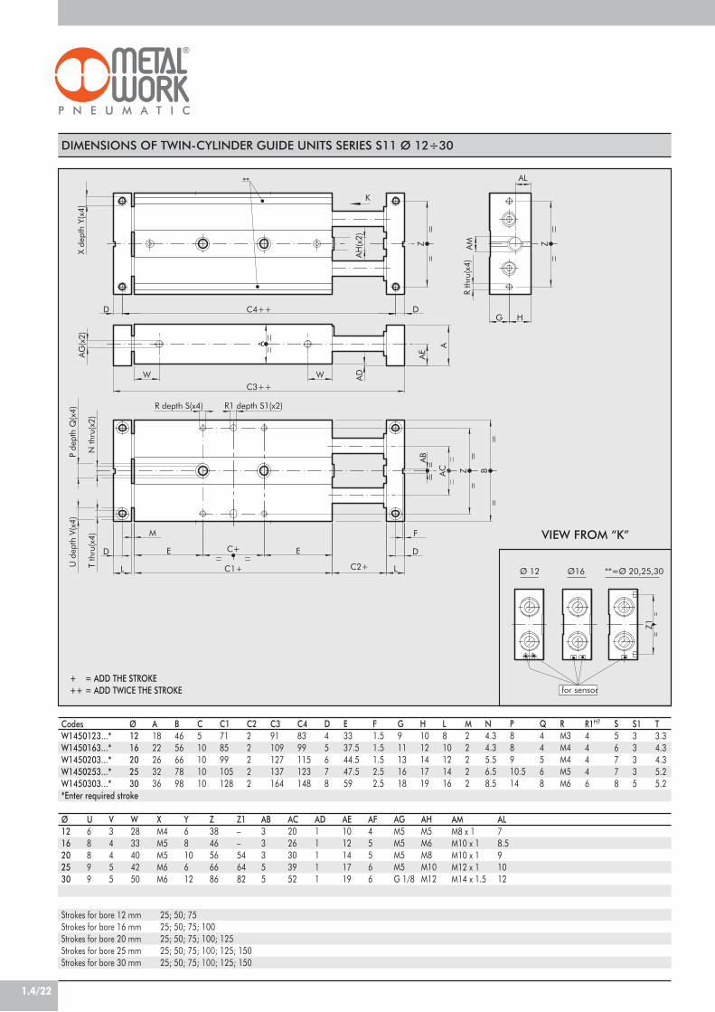
1.4/22
DIMENSIONS OF TWIN-CYLINDER GUIDE UNITS SERIES S11 Ø 12÷30
CodesW1450123...*W1450163...*W1450203...*W1450253...*W1450303...**Enter required stroke
Ø1216202530
U68899
V34455
W2833404250
XM4M5M5M6M6
Y6810612
Z3846566686
AB33355
AC2026303952
AD11111
AE1012141719
AF45566
AGM5M5M5M5G 1/8
AHM5M6M8M10M12
Strokes for bore 12 mmStrokes for bore 16 mmStrokes for bore 20 mmStrokes for bore 25 mmStrokes for bore 30 mm
25; 50; 7525; 50; 75; 10025; 50; 75; 100; 12525; 50; 75; 100; 125; 15025; 50; 75; 100; 125; 150
+ = ADD THE STROKE++ = ADD TWICE THE STROKE
**=Ø 20,25,30
for sensor
Ø16Ø 12
Z1
VIEW FROM “K”
K
fo
ØØ 12
**
R depth S(x4) R1 depth S1(x2)
AM
AL
P de
pth
Q(x
4)
N th
ru(x
2)
U d
epth
V(x
4)
D
T th
ru(x
4)
A
D
L
W
AG(x
2)
E
M
C1+
C4++
C3++
HG
W
AH(x
2)
E
D
AB
D
LC2+
F
AE
A
AD
X de
pth
Y(x4
)
R th
ru(x
4)
BZ
ZZ
AC
C+
Z1––546482
Ø1216202530
A1822263236
B4656667898
C510101010
C1718599105128
C222222
C391109127137164
C48399115123148
D45678
E3337.544.547.559
F1.51.51.52.52.5
G911131618
H1012141719
L810121416
M22222
N4.34.35.56.58.5
P88910.514
Q44568
RM3M4M4M5M6
S56778
T3.34.34.35.25.2
R1H7
44446
S133335
AMM8 x 1M10 x 1M10 x 1M12 x 1M14 x 1.5
AL78.591012

1.4/23
1DIMENSIONS OF TWIN-CYLINDER GUIDE UNITS WITH SHOCK ABSORBERS SERIES S11 Ø 12÷30
CodesW1450124...*W1450164...*W1450204...*W1450254...*W1450304...**Enter required stroke
Ø1216202530
U68899
V34455
W1415161921
XM4M5M5M6M6
Y68101212
Z3846566686
AB33355
AC2026303952
AD11111
AE1012141719
AF45566
AGM5M5M5M5G 1/8
AH3035353660
Strokes for bore 12 mmStrokes for bore 16 mmStrokes for bore 20 mmStrokes for bore 25 mmStrokes for bore 30 mm
25; 50; 7525; 50; 75; 10025; 50; 75; 100; 12525; 50; 75; 100; 125; 15025; 50; 75; 100; 125; 150
AMM8 x 1M10 x 1M10 x 1M12 x 1M14 x 1.5
+ = ADD THE STROKE++ = ADD TWICE THE STROKE
K
**
for sensor
Ø16Ø 12
**
AG(x2)
R1 depth S1(x2)R depth S(x4)
HG
W W
A
X de
pth
Y(x4
)
D
P de
pth
Q(x
4)
N th
ru(x
2)
M
L C1+
ED E
T th
ru(x
4)
U d
epth
V(x
4)
C3++
AD
Z
C4++
AB
D
AH max AM
F
C2+ L
D
R th
ru(x
4)
Z
BZAC
C+
AE
AL
A
Z1––546982
Ø1216202530
A1822263236
B4656667898
C510101010
C14550556070
C222222
C365748392106
C45764717890
D45678
E202022.52530
F1.51.51.52.52.5
G911131618
H1012141719
L810121416
M22222
N4.34.35.56.58.5
P88910.514
Q44568
RM3M4M4M5M6
S56778
T3.34.34.35.25.2
S133335
R1H7
44446
AL78.591012
**=Ø 20,25,30
for sensor
Ø16Ø 12
Z1
VIEW FROM “K”

1.4/24
DIMENSIONS OF TWIN-CYLINDER GUIDE UNITS, BALL BEARING VERSIONWITH SHOCK ABSORBERS SERIES S11 Ø 12÷30
CodesW1450125...*W1450165...*W1450205...*W1450255...*W1450305...**Enter required stroke
Ø1216202530
U68899
V34455
W2833404250
XM4M5M5M6M6
Y6810612
Z3846566686
AB33355
AC2026303952
AD11111
AE1012141719
AF45566
AGM5M5M5M5G 1/8
AH3035353660
Strokes for bore 12 mmStrokes for bore 16 mmStrokes for bore 20 mmStrokes for bore 25 mmStrokes for bore 30 mm
25; 50; 7525; 50; 75; 10025; 50; 75; 100; 12525; 50; 75; 100; 125; 15025; 50; 75; 100; 125; 150
AMM8 x 1M10 x 1M10 x 1M12 x 1M14 x 1.5
+ = ADD THE STROKE++ = ADD TWICE THE STROKE
**=Ø 20,25,30
for sensor
Ø16Ø 12
Z1
AG(x2)
K
**=Ø 20,25,3
for sensor
Ø16Ø 12
**
R1 depth S1(x2)
AL
R depth S(x4)
R th
ru(x
4)
A
N th
ru(x
2)
E
C1+
W
BZ
G H
X de
pth
Y(x4
)
D
L
F
AMAH max
D
AB
C2+
AD
E
W
U d
epth
V(x
4)
T th
ru(x
4)
D
L
M
P de
pth
Q(x
4)
D C4++
Z
ZAC
C+
A
AE
C3++
Z1
VIEW FROM “K”
Z1––546482
Ø1216202530
A1822263236
B4656667898
C510101010
C1718599105128
C222222
C391109127137164
C48399115123148
D45678
E3337.544.547.559
F1.51.51.52.52.5
G911131618
H1012141719
L810121416
M22222
N4.34.35.56.58.5
P88910.514
Q44568
RM3M4M4M5M6
S56778
T3.34.34.35.25.2
R1H7
44446
S133335
AL78.591012

1.4/25
1
ACCESSORIES
SHOCK ABSORBERS Description
Shock absorbers PM8 MC2 + nut M8x1Shock absorbers PM10 MF2 + nut M10x1Shock absorbers PR015 MF1 + nut M12x1Shock absorbers PR025 MC2 + nut M14x1.5
Code
0950004001095000400209500040030950004004
Ø
ø12ø16-20ø25ø30
MAGNETIC SENSOR Ø 4, FOR SLIDE S11 Ø12
DescriptionSensor REED 2 wires 24 VDC 1mSensor HALL 3 wires 24 VDC 2m
CodeW0950044180W0950045390*
* For tecnical data of sensor, see page 1.1/24
5.8 500
4.9
BAR FOR GROOVING
Note: the code corresponds to 1 piece
CodeW0950000160
DescriptionBAR FOR GROOVING L=500 mm
Note: the code corresponds to 1 piece
RETRACTABLE SENSOR WITH INSERTION FROM ABOVE, FOR SLIDE S11 Ø16÷30
DescriptionHALL N.O. SENSOR, VERTICAL INSERTION 2.5mHALL N.O. SENSOR, VERTICAL INSERTION 300 mm M8REED N.O. SENSOR, VERTICAL INSERTION 2.5mREED N.O. SENSOR, VERTICAL INSERTION 300 mm M8HALL N.O. SENSOR, VERTICAL INSERTION 2m ATEX
CodeW0952025390W0952029394W0952022180W0952028184W0952125556
This type of sensor can be inserted in the slot of the sensor from above. This means thecylinder heads do not require a through opening.
black
HALL EFFECT+
+
brown
blue
PNP
blue
black
-
blue
brown
brown
34
1
REED EFFECT +
+-
brown
3blue 4
1
M8
M8
WIRING DIAGRAM TECHNICAL DATA
Type of contactSwitchSupply voltage (Ub) VPower WVoltage variationVoltage drop VInput current mAOutput current mASwitching frequency HzShort-circuit protectionOver-voltage suppressionPolarity inversion protectionEMCLED displayMagnetic sensitivityRepeatabilityDegree of protection (EN 60529)Vibration and shock resistanceTemperature range °CSensor capsule material2.5m/2m connecting cableConnecting cable with M8x1Wire NO.
Reed Effetto Hall Effetto HallN.O. N.O. N.O.
- PNP PNP10 ÷ 30 AC/DC 10 ÷ 30 DC 18 ÷ 30 DC3 (peak valve=6) 3 ! 1.7
- ! 10% di Ub ! 10% di Ub- ! 2 ! 2.2- ! 10 ! 10
! 100 ! 100 ! 70! 400 ! 5000 1000
- Yes Yes- Yes Yes- Yes Yes
EN 60 947-5-2 EN 60 947-5-2 EN 60 947-5-2Yellow Yellow Yellow
2,8 mT ±25% 2,8 mT ±25% 2.6! 0,1 mT ! 0,1 mT ! 0,1 (Ub and ta fixed)
IP 67 IP 67 IP 68, IP 69K30 g, 11 ms, 10÷55 Hz, 1mm 30 g, 11 ms, 10÷55 Hz, 1mm 30 g, 11 ms, 10÷55 Hz, 1mm -25 ÷+75 -25 ÷ +75 -20 ÷ +45
PA66 + PA6I/6T PA66 + PA6I/6T PAPVC; 2 x 0,12 mm2 PVC; 3 x 0,14 mm2 PVC; 3 x 0,12 mm2
Polyurethane; 2 x 0,14 mm2 Polyurethane; 3 x 0,14 mm2 -2 3 3
ATEX

1.4/26
23489 67 5
10
A
B
1 11
Ft
Fp
Two sliding systems are available:• on bushes• on ball bearingsThe structure is made up of two paired through-rod cylinderswith a common anodized aluminium body with grooves formounting the retractable sensor.Five bores available: 2xØ16; 2xØ20; 2xØ25; 2xØ30.The rods are joined together by means of a plate on whichthe mechanical limit switches or hydraulic shock absorberscan be mounted.The compressed air ports are at the end of the piston rods.
TWIN CYLINDER SLIDEWITH FIXED PLATES SERIES S12
FluidPressure rangeTemperature range °CPiston speed mm/sVersionsBores mmPiston rod diameter mmStrokes mm
Weight = X + (Y · C) kgC= strokeSliding version
Ball bearing version
Theoretical thrust NP = relative pressure in barLoads with sliding version N
Loads with ball bearing version N
TECHNICAL FEATURES20!m filtered air
1.5 to 7 bar (0.15 to 0.7 MPa)5 to +60
30 to 200 mm/sWith sliding bushes / With ball bearing bushes / With stop screw / With hydraulic shock absorbersi
16 20 25 308 10 12 16
25 25 25 2560 50 50 5075 75 75 75
100 100 100 100– 125 125 125– – 150 150
X = 0.25 X = 0.5 X = 0.7 X = 1.24Y = 0.0035 Y = 0.045 Y 0.007 Y = 0.01
X = 0.37 X = 0.78 X = 1.04 X = 1.98Y = 0.0035 Y = 0.045 Y = 0.007 Y = 0.01
30xP 47xP 75xP 101xP(The values shown refer to the min. and max. strokes)
Fr: 20÷4 Fr: 35÷4.5 Fr: 50÷5.4 Fr: 80÷12Fp: 4÷1.5 Fp: 12÷3 Fp: 15÷3.5 Fp: 20÷4.5Fr: 35÷6.5 Fr: 58÷7 Fr: 80÷8 Fr: 130÷18Fp: 11÷3 Fp: 18÷5 Fp: 23÷6 Fp: 50÷8
COMPONENTS
! FLANGE: anodized aluminium" WASHER: steel# BUFFER: rubber$ ADJUSTABLE STRIKER PLATE: Zinc-plated steel% BASE: brass& PISTON: brass' MAGNET: Plastoferrite( CYLINDER BODY: anodized aluminium) STATIC O-RINGS: NBR* BUSH: ball bearing+ VITE: con alimentazione pneumatica
A = Version with sliding bush
B = Version with ball bearing bush

1.4/27
1DIMENSIONS OF TWIN-CYLINDER SLIDE SERIES S12 Ø 16÷30
CodesW1460162...*W1460202...*W1460252...*W1460302...*
*Enter required stroke
Ø16202530
U8899
V4455
W15161921
XM5M5M6M6
Y8101212
Z46566686
AB3355
AC26303952
AD1111
AE12141719
AF5566
AGM5M5M5G 1/8
AHM6M8M10M12
Strokes for bore 16 mmStrokes for bore 20 mmStrokes for bore 25 mmStrokes for bore 30 mm
25; 50; 75; 10025; 50; 75; 100; 12525; 50; 75; 125; 15025; 50; 75; 125; 150
+ = ADD THE STROKE++ = ADD TWICE THE STROKE
VIEW FROM “K”
Z1–546482
R1H7
4446
S13335
Ø16202530
A22263236
B56667898
C10101010
C150556070
C22222
C3748392106
C464717890
D5678
E2022.52530
F1.51.52.52.5
G11131618
H12141719
L10121416
M2222
N4.35.56.58.5
P8910.514
Q4568
RM4M4M5M6
S6778
T4.34.35.25.2
AMM10 x 1M10 x 1M12 x 1M14 x 1.5
AL8.591012
**=Ø 20,25,30Ø16
for sensor
Z1
K*
Ø16
for se
R depth S(x4) R1 depth S1(x2)
AM
AL
R th
ru(x
4)A
G(x
2)
FM
L C1+ C2+ L
ED C+ E D
AB
BAC Z
AE
C3++
W ADW
AG
(x2)
A A
C4++D D
AH
(x2)
U d
epth
V(x
4)P
dept
h Q
(x4)
N th
ru(x
2)T
thru
(x4)
Z
G H
ZACX
dept
h Y(
x4)

1.4/28
DIMENSIONS OF TWIN-CYLINDER SLIDE SERIES S12 Ø 16÷30
CodesW1460163...*W1460203...*W1460253...*W1460303...*
*Enter required stroke
Ø16202530
U8899
V4455
W33404250
XM5M5M6M6
Y810612
Z46566686
AB3355
AC26303952
AD1111
AE12141719
AF5566
AGM5M5M5G 1/8
AHM6M8M10M12
Strokes for bore 12 mmStrokes for bore 16 mmStrokes for bore 20 mmStrokes for bore 25 mm
25; 50; 75; 10025; 50; 75; 100; 12525; 50; 75; 125; 15025; 50; 75; 125; 150
+ = ADD THE STROKE++ = ADD TWICE THE STROKE
VIEW FROM “K”
Z1–546482
Ø16202530
A22263236
B56667898
C10101010
C18599105128
C22222
C3109127137164
C499115123148
D5678
E37.544.547.559
F1.51.52.52.5
G11131618
H12141719
L10121416
M2222
N4.35.56.58.5
P8910.514
Q4568
RM4M4M5M6
S6778
T4.34.35.25.2
R1H7
4446
S13335
AMM10 x 1M10 x 1M12 x 1M14 x 1.5
AL8.591012
*K
Ø16
for se
R depth S(x4) R1 depth S1(x2)
X de
pth
Y(x4
)
E
AH
(x2)
WC3++
C4++
C1+
C+
M
E
Z
D
BAC
AB
D
LC2+
F
Z
AE
A
AG
(x2)
W AD
L
D
A
T th
ru(x
4)
D
U d
epth
V(x
4)
N th
ru(x
2)
P de
pth
Q(x
4)
ZAC
HG
AG
(x2)
R th
ru(x
4)
AM
AL
**=Ø 20,25,30Ø16
for sensor
Z1

1.4/29
1DIMENSIONS OF TWIN-CYLINDER SLIDE WITH SHOCK ABSORBERS SERIES S12 Ø 16÷30
CodesW1460164...*W1460204...*W1460254...*W1460304...*
*Enter required stroke
Ø16202530
U8899
V4455
W15161921
XM5M5M6M6
Y8101212
Z46566686
AB3355
AC26303952
AD1111
AE12141719
AF5566
AGM5M5M5G 1/8
AH35353660
Strokes for bore 16 mmStrokes for bore 20 mmStrokes for bore 25 mmStrokes for bore 30 mm
25; 50; 75; 10025; 50; 75; 100; 12525; 50; 75; 125; 15025; 50; 75; 125; 150
AMM10 x 1M10 x 1M12 x 1M14 x 1.5
+ = ADD THE STROKE++ = ADD TWICE THE STROKE
Z1–546482
VIEW FROM “K”
Ø16202530
A22263236
B56667898
C10101010
C150556070
C22222
C3748392106
C464717890
D5678
E2022.52530
F1.51.52.52.5
G11131618
H12141719
L10121416
M2222
N4.35.56.58.5
P8910.514
Q4568
RM4M4M5M6
S6778
T4.34.35.25.2
R1H7
4446
S13335
AL8.591012
AG(x2)
K*
**=Ø 20,25Ø16
for sensor
AL
AA
E
U d
epth
V(x
4)
R th
ru(x
4)
G H
ZAC
AG
(x2)
D
LC2+
F
AMAH max
D
AB
C4++
Z
AD
C3++
T th
ru(x
4)
EC+D E
C1+L
M
N th
ru(x
2)
P de
pth
Q(x
4)
D
A
WW
BAC Z
X de
pth
Y(x4
)
R depth S(x4) R1 depth S1(x2)
Z1
**=Ø 20,25,30Ø16
for sensor
Z1

1.4/30
DIMENSIONS OF TWIN-CYLINDER SLIDE WITH SHOCK ABSORBERS SERIES S12 Ø 16÷30
CodesW1460165...*W1460205...*W1460255...*W1460305...*
*Enter required stroke
Ø16202530
U8899
V4455
W33404250
XM5M5M6M6
Y810612
Z46566686
AB3355
AC26303952
AD1111
AE12141719
AF5566
AGM5M5M5G 1/8
AH35353660
Strokes for bore 16 mmStrokes for bore 20 mmStrokes for bore 25 mmStrokes for bore 30 mm
25; 50; 75; 10025; 50; 75; 100; 12525; 50; 75; 125; 15025; 50; 75; 125; 150
AMM10 x 1M10 x 1M12 x 1M14 x 1.5
+ = ADD THE STROKE++ = ADD TWICE THE STROKE
VIEW FROM “K”
Z1–546482
Ø16202530
A22263236
B56667898
C10101010
C18599105128
C22222
C3109127137164
C499115123148
D5678
E37.544.547.559
F1.51.52.52.5
G11131618
H12141719
L10121416
M2222
N4.35.56.58.5
P8910.514
Q4568
RM4M4M5M6
S6778
T4.34.35.25.2
R1H7
4446
S13335
AL8.591012
K
**=Ø 20,25,3Ø16
AG(x2)
for sensor
X de
pth
Y(x4
)
C4++D
P de
pth
Q(x
4)
M
L
D
T th
ru(x
4)
U d
epth
V(x
4)
W
E
AD
C2+
ZAC
AB
D
AH max AM
F
L
D
Z B
C3++
AE
W
C1+
E
N th
ru(x
2)
A
C+
HG
AG
(x2)
R th
ru(x
4)
AC Z
R depth S(x4) R1 depth S1(x2)
A
Z1
**=Ø 20,25,30Ø16
for sensor
Z1

1.4/31
1
ACCESSORIES
RETRACTABLE SENSOR WITH INSERTION FROM ABOVE, FOR SLIDE S12 Ø16÷30
DescriptionHALL N.O. SENSOR, VERTICAL INSERTION 2.5mHALL N.O. SENSOR, VERTICAL INSERTION 300 mm M8REED N.O. SENSOR, VERTICAL INSERTION 2.5mREED N.O. SENSOR, VERTICAL INSERTION 300 mm M8HALL N.O. SENSOR, VERTICAL INSERTION 2m ATEX
CodeW0952025390W0952029394W0952022180W0952028184W0952125556
This type of sensor can be inserted in the slot of the sensor from above. This means thecylinder heads do not require a through opening.
black
HALL EFFECT+
+
brown
blue
PNP
blue
black
-
blue
brown
brown
34
1
REED EFFECT +
+-
brown
3blue 4
1
M8
M8
WIRING DIAGRAM TECHNICAL DATA
Type of contactSwitchSupply voltage (Ub) VPower WVoltage variationVoltage drop VInput current mAOutput current mASwitching frequency HzShort-circuit protectionOver-voltage suppressionPolarity inversion protectionEMCLED displayMagnetic sensitivityRepeatabilityDegree of protection (EN 60529)Vibration and shock resistanceTemperature range °CSensor capsule material2.5m/2m connecting cableConnecting cable with M8x1Wire NO.
Reed Effetto Hall Effetto HallN.O. N.O. N.O.
- PNP PNP10 ÷ 30 AC/DC 10 ÷ 30 DC 18 ÷ 30 DC3 (peak valve=6) 3 ! 1.7
- ! 10% di Ub ! 10% di Ub- ! 2 ! 2.2- ! 10 ! 10
! 100 ! 100 ! 70! 400 ! 5000 1000
- Yes Yes- Yes Yes- Yes Yes
EN 60 947-5-2 EN 60 947-5-2 EN 60 947-5-2Yellow Yellow Yellow
2,8 mT ±25% 2,8 mT ±25% 2.6! 0,1 mT ! 0,1 mT ! 0,1 (Ub and ta fixed)
IP 67 IP 67 IP 68, IP 69K30 g, 11 ms, 10÷55 Hz, 1mm 30 g, 11 ms, 10÷55 Hz, 1mm 30 g, 11 ms, 10÷55 Hz, 1mm -25 ÷+75 -25 ÷ +75 -20 ÷ +45
PA66 + PA6I/6T PA66 + PA6I/6T PAPVC; 2 x 0,12 mm2 PVC; 3 x 0,14 mm2 PVC; 3 x 0,12 mm2
Polyurethane; 2 x 0,14 mm2 Polyurethane; 3 x 0,14 mm2 -2 3 3
ATEX
SHOCK ABSORBERS Description
Shock absorbers PM10 MF2 + nut M10x1Shock absorbers PR015 MF1 + nut M12x1Shock absorbers PR025 MC2 + nut M14x1.5
Code
095000400209500040030950004004
Ø
ø16-20ø25ø30
BAR FOR GROOVING
Note: the code corresponds to 1 piece
Code
W0950000160
Description
BAR FOR GROOVING L=500 mm
Note: the code corresponds to 1 piece5.8 500
4.9

1.4/32
PRECISION SLIDES SERIES S13
1 92 3 4 765 8
211 8 141310 12 15 12
Series S13 precision slides feature a dual-acting pneumaticcylinder that has the sole purpose of pushing and pullingthe load, a ground steel guide that is integral with the body,and a ball recirculation pad that is fixed onto the movingtable and is designed to withstand all the loads andmovements applied. This ensures accurate movement withvirtually no play, and the piston rods do not suffer wear asthere are no lateral loads. All the slides are equipped withsensor magnets.The body can be secured on many sides. The load sidecan be fixed onto the table from the top or the front. Thecompressed air supply can be connected on three sides.The retractable sensors can be fitted on the right or on theleft. All these possibilities make the application extremelyflexible. The width is extremely reduced to allow installationin small spaces and the combination of several reduced-pitch slides.
Pressure range barOperating temperature °CFluidMinimum and maximum speed mm/sPneumatic fittingsType of guideVersionsBore mmStrokes mm
Theoretical thrust force, at 6 bar NTheoretical pull force, at 6 bar NAdmitted loadsAdmitted kinetic energy JouleStroke tolerance mmAssembly positionWeight Kg
TECHNICAL DATA2 ÷ 8 (0,2 ÷ 0,8 MPa)
- 10 to +70Lubricated and unlubricated compressed air at 20 µm, must be uninterrupted when lubricated
30 and 500M5
Ball recirculationMagnetic dual-acting with rubber buffer
Ø 6 Ø10 Ø16 Ø 2010 10 10 1025 25 25 25--- --- 50 5017 47 120 18813 40 104 158
See diagrams0,012 0,025 0,050 0,100
0 / +1,0any (horizontal and vertical)
See table
COMPONENTS
! NUT: stainless steel" SNAP RING: galvanised steel# FRONT BASE: bronze$ BODY: anodized aluminium% GUIDE: tempered stainless steel& PISTON: aluminium' BALL RECIRCULATION PAD: stainless
steel( BUFFER: NBR) REAR BASE: anodized aluminium* PLATE: anodized aluminium+ PISTON ROD GASKET: type EM, NBR, O-RING: NBR- PISTON ROD: stainless steel. PISTON GASKET: type PZ, NBR/ MAGNET: neodymium (Ø6 and Ø10) plastoferrite (Ø16 and Ø20)

1.4/33
1
102550
WEIGHT (gr)bore
6890---
125160---
230280350
455550660
6stroke
10 16 20102550
WEIGHT OF MOVING PART(gr)bore
3040---
5068---
100125167
180220290
6stroke
10 16 20
V
M
L
M (kg) = Mass appliedL (mm) = Distance between the axis of the piston rod
and the barycentre of the massv (mm/s) = Velocity of the slidevert = Limit with vertical movement
MASS/VELOCITY DIAGRAM
ADMITTED LOADS DIAGRAM
500
0.2 0.50.40.350
0.10.05
L<=100
200
M [kg]
v[mm/s]
100
400
300
L<=40
L<=200
S13-6
0.85 0.3 0.4
500
S13-10
50
vert200
v[mm/s]
100
400
300
2.51 2 M [kg]0.50.1 0.2
L<=100
L<=40
L<=200
L<=100
L<=40
L<=200
vert
v[mm/s]
500
50
200
100
400
300
60.3 0.40.5 2 3 74 510.2 M [kg]
S13-16
6 7 M [kg]
L<=300
10
S13-20
vert
L<=40
L<=100
L<=200
0.3 0.4
500
50
200
v[mm/s]
100
400
300
1 20.50.2 3 4 50.1
S13-6
S13-16
S13-10
S13-20

1.4/34
FIXING OPTIONS
IN
OUT
OUT
IN
IN
OUT
IN
OUTThe compressed air supply can be from the back, fromthe left or from the right. The slide comes with holes onthe left and right that are plugged with screws and O-ring seals. If you wish to use the holes, remove the screwsand O-rings and fix them in the holes in the back,applying a drop of adhesive to the screw thread.
COMPRESSED-AIR SUPPLY
E
C
A B
D
F
FIXING THE BODY:Lateral, via the through holes.Lateral, on the hole threads.Rear, on the threaded holes.Vertical, on the threaded holes.
FIXING THE MOVING TABLE:Front, on the threaded holes.Top, on the threaded holes.
N.B. Since the table is supported by a ball guide/pad, avoid applying excessive torques or forces.When securing the screws, hold the table, not the body, so that the torque discharges through the ball pad.
C
A
B
D
EF

1.4/35
1
N°3+3 x Ø
L
M5 (IN)M5 (OUT)
M5 (IN)
M5 (OUT)
INOUT
M5 (IN)
M5 (OUT)
R VN°2 x ØA H7
depth "ps"
N°4 x MAthrough
N° 2 x M5 air port (OUT)
N° 2 x M5 air port (IN)
M5 air port(OUT)
N°3 x MLthrough
N°2 x ØA H7depth "ps"
N°4 x MAdepth "pf "
N°4 x MAdepth "pf "
N°(Nfx2) x MAthrough
N°2 x ØA H7depth "ps"
depth "pn"
M5 air port(IN)
J
U
CD
G
A
I
H
Q
P N
O
E F
B
S
XY
W
K
M
L
DL
T+
LT+
DIMENSIONS
CodeW1471063...*W1471103...*
*W1471163...*W1471203...*
*Enter the stroke in mm (e.g. Ø6 stroke 10=W1471063010)
T551010
U9131720
V16202532
W10.5131720
X18202532
Y19232734
pn3.54.54.57.5
MLM4M5M5M6
DL4556
Standard strokes:Bore Ø6 ->Bore Ø10 ->Bore Ø16 ->Bore Ø20 ->
10; 25 mm10; 25 mm10; 25; 50 mm10; 25; 50 mm
+ = ADD THE STROKE
ØL67.57.59.5
P8111414
R15192431
Ø6101620
LT31354252.5
B19232734
C18202532
D1012.512.515
E394753.564.5
F384652.563.5
G5.57.51011
I2.943.754.5
J7.591010.5
K15182634
MAM3M4M4M5
pf5679
ØA2233
ps4.54.57.57.5
L9111620
M14.515.51923
ON/2N/2N/2N/2
Q9111620
S10121215
Ø
6
10
16
20
Stroke10251025102550102550
A14301430204060204070
N10301030103025103025
H426249695878986484104
NF2222223223

1.4/36
Ø4 MAGNETIC SENSOR
CODEW0950044180W0950045390
DESCRIPTION2-wire reed magnetic sensor 24 VDC 1m3 wire electronic magnetic sensor
ACCESSORIES
NOTES
black
HALL EFFECT+
+
brown
blue
PNP
blue
black
-
brown
34
1
M8
WIRING DIAGRAM FOR W0950045390 TECHNICAL DATA
SwitchTension in DC VTension in AC VCurrent at 25°C APower (ohmic load) WOn time µsOff time µsOn point GaussOff point GaussElectric life (pulses)On voltage drop VNominal operating point GaussOperating frequency HzPolarity reversal protectionShort-circuit protectionDegree of protection (EN 60529)Temperature range °CSensor capsule materialLED displayWiring NO.
Effetto HallPNP
6÷30---0,2
max 60,80,33025
109<1
30÷50max 200
YesNO
IP 67-10 ÷ +70
PA (+G)Yellow
3