Siemens Ltda. 2009. All rights reserved.SINAMICS S120 Date: 21.07.2009
Preparations for commissioning
supply 1
3
4
2
5
1. Component wiring2. Rules for wiring with
DRIVE-CLiQ3. Activating online operation
via PROFIBUS 4. STARTER commissioning
tool5. CU320 has the right
CompactFlash Card

Siemens Ltda. 2009. All rights reserved.SINAMICS S120 Date: 21.07.2009
Preparation 1: wiring (example)
• Main switch• Line fuses• SITOP with fuses• 24VDC for drive components and EP• DRIVE-CLiQ wiring• Line contactor with DI to CU320• Line reactor or reactor + filter• Cables to motors and encoders• Grounding
example:CU320 with ALM, 2 Motor module with Motor,2 Motor encoders, 1 external encoder over 3 SMI
Siemens Ltda. 2009. All rights reserved.SINAMICS S120 Date: 21.07.2009
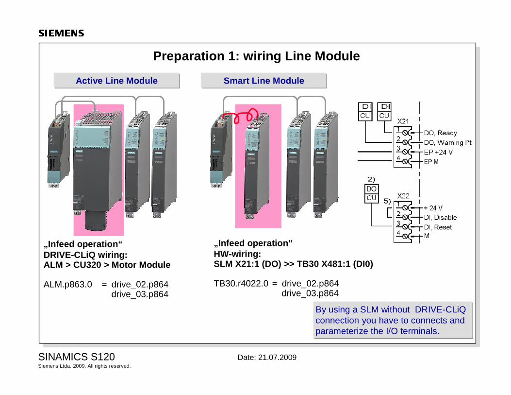
Preparation 1: wiring Line Module
Active Line Module
„Infeed operation“DRIVE-CLiQ wiring: ALM > CU320 > Motor Module
ALM.p863.0 = drive_02.p864drive_03.p864
Smart Line Module
„Infeed operation“HW-wiring: SLM X21:1 (DO) >> TB30 X481:1 (DI0)
TB30.r4022.0 = drive_02.p864drive_03.p864
By using a SLM without DRIVE-CLiQconnection you have to connects and parameterize the I/O terminals.
Siemens Ltda. 2009. All rights reserved.SINAMICS S120 Date: 21.07.2009
Sensor Module SMC/SMEoder DRIVE-CLiQ Motor
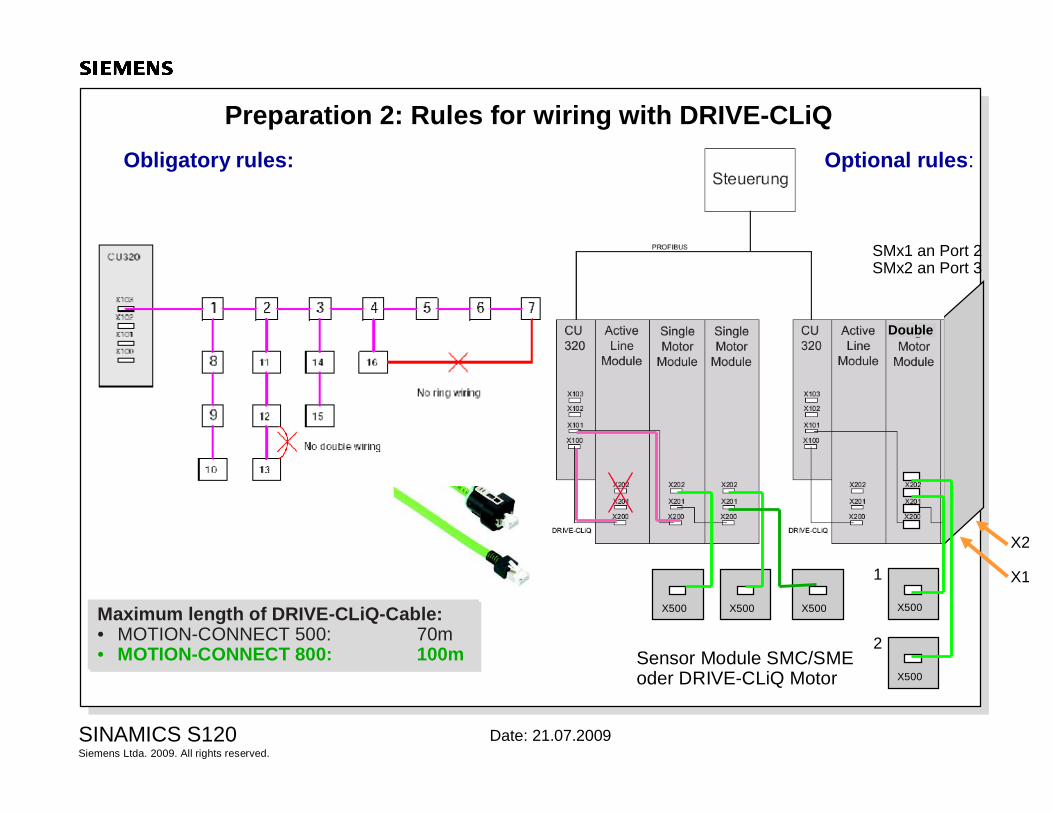
Preparation 2: Rules for wiring with DRIVE-CLiQObligatory rules:
Maximum length of DRIVE-CLiQ-Cable:• MOTION-CONNECT 500: 70m• MOTION-CONNECT 800: 100m
Maximum length of DRIVE-CLiQ-Cable:• MOTION-CONNECT 500: 70m• MOTION-CONNECT 800: 100m
X500 X500 X500
Double
X500
X500
X2
X11
2
SMx1 an Port 2SMx2 an Port 3
Optional rules:
Siemens Ltda. 2009. All rights reserved.SINAMICS S120 Date: 21.07.2009
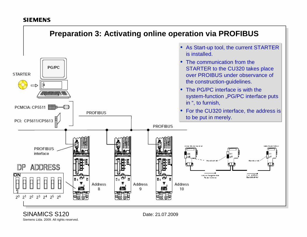
Preparation 3: Activating online operation via PROFIBUS• As Start-up tool, the current STARTER
is installed. • The communication from the
STARTER to the CU320 takes place over PROIBUS under observance of the construction-guidelines.
• The PG/PC interface is with the system-function „PG/PC interface puts in “, to furnish,
• For the CU320 interface, the address is to be put in merely.
Siemens Ltda. 2009. All rights reserved.SINAMICS S120 Date: 21.07.2009
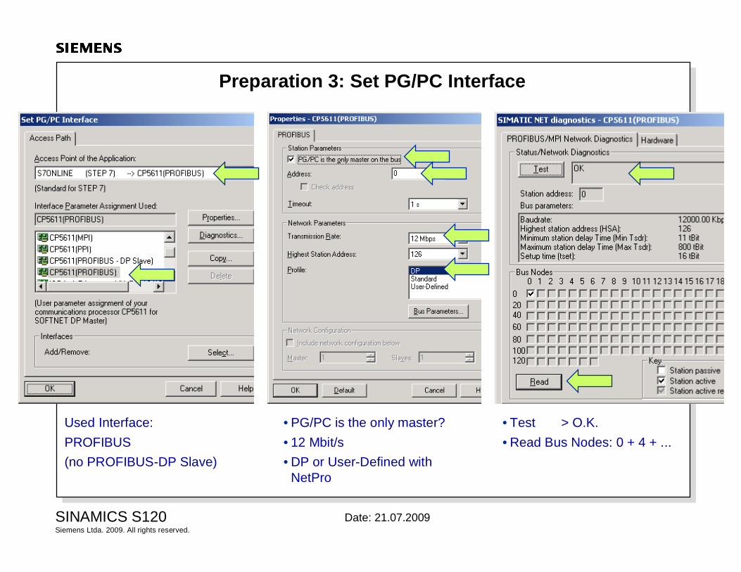
Preparation 3: Set PG/PC Interface
Used Interface:PROFIBUS(no PROFIBUS-DP Slave)
• PG/PC is the only master?• 12 Mbit/s• DP or User-Defined with
NetPro
• Test > O.K.• Read Bus Nodes: 0 + 4 + ...

Siemens Ltda. 2009. All rights reserved.SINAMICS S120 Date: 21.07.2009
Preparation 4: SINAMICS Firmware and STARTER Software
current FW-version
SINAMICS:V02.05.00.00
current SW-version
STARTER/SCOUT:V4.1.2.4
Siemens Ltda. 2009. All rights reserved.SINAMICS S120 Date: 21.07.2009
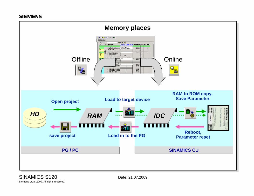
Memory places
V02.01.01
HDHD RAMRAM
RAM to ROM copy,Save Parameter
SINAMICS CUPG / PC
Load in to the PGsave projectReboot,
Parameter reset
Load to target deviceOpen project
OnlineOffline
IDCIDC

Siemens Ltda. 2009. All rights reserved.SINAMICS S120 Date: 21.07.2009
Structure of the CompactFlash Card S120
1 userparameter file
For example:PS xx00= GeneralPS xx01= Object 1: CUPS xx02= Object 2/3: DrivePS xx03= Object 4: TB30PS xx99= General
n savedparameter files+
V02.01.01
System data
User data
License
FW for components
GSD data
CU loader
The following is saved on the CompactFlash Card:• The firmware of the CU and the components• The user parameters (PF1: each DO =1 file)• Additional parameter files for factory reset

Siemens Ltda. 2009. All rights reserved.SINAMICS S120 Date: 21.07.2009
Save and reset parameters
A) Use IconsLoad project to target system• all Project data to target system
drive 1, drive 2, SIMOTION
• With/without RAM t0 ROM copy:
Download• Project-part of the marked device
A upload to PGB download to target systemC restore factory settings (p976=1)D copy RAM to ROM
A B C D
Siemens Ltda. 2009. All rights reserved.SINAMICS S120 Date: 21.07.2009
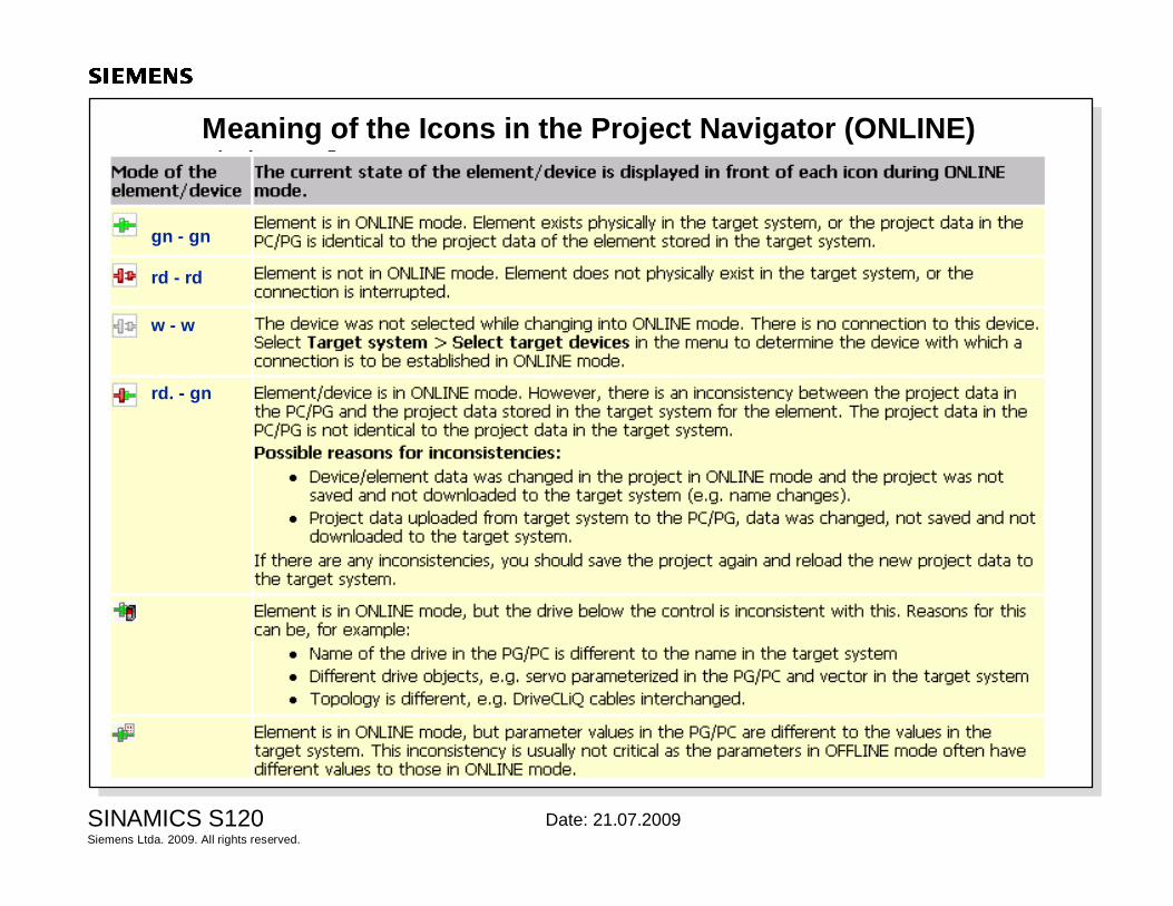
Meaning of the Icons in the Project Navigator (ONLINE)
gn - gn
rd - rd
rd. - gn
w - w

Siemens Ltda. 2009. All rights reserved.SINAMICS S120 Date: 21.07.2009
Topology and Compare of Components

Siemens Ltda. 2009. All rights reserved.SINAMICS S120 Date: 21.07.2009
Servo: Closed-loop control
M
Motor
G
sensorSpeed
- nist
nsoll
Position
- xist
xsoll
Act. current
- Iist
Isoll PWM
32
IUIVIW
Iq
IdMotor-model
Iq
IdωM
ϕM
KV...Gain KP... GainTN... Integral Time
KP... GainTN.. Integral Time
Position controler
Torque precontrol
Speed precontrolSpeed controller Current controller
Gating unitEncoder
Rotor pos.
Siemens Ltda. 2009. All rights reserved.SINAMICS S120 Date: 21.07.2009
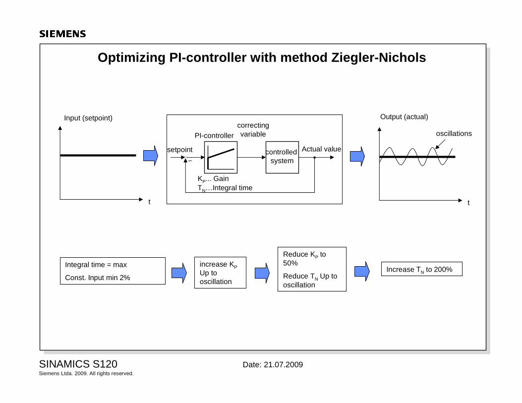
Optimizing PI-controller with method Ziegler-Nichols
controlled system
PI-controllercorrecting variable
setpoint Actual value
KP... GainTN…Integral time
Input (setpoint)
t
Output (actual)
Integral time = max
Const. Input min 2%
increase KP Up to oscillation
Increase TN to 200%
Reduce KP to 50%
Reduce TN Up to oscillation
t
oscillations
Siemens Ltda. 2009. All rights reserved.SINAMICS S120 Date: 21.07.2009
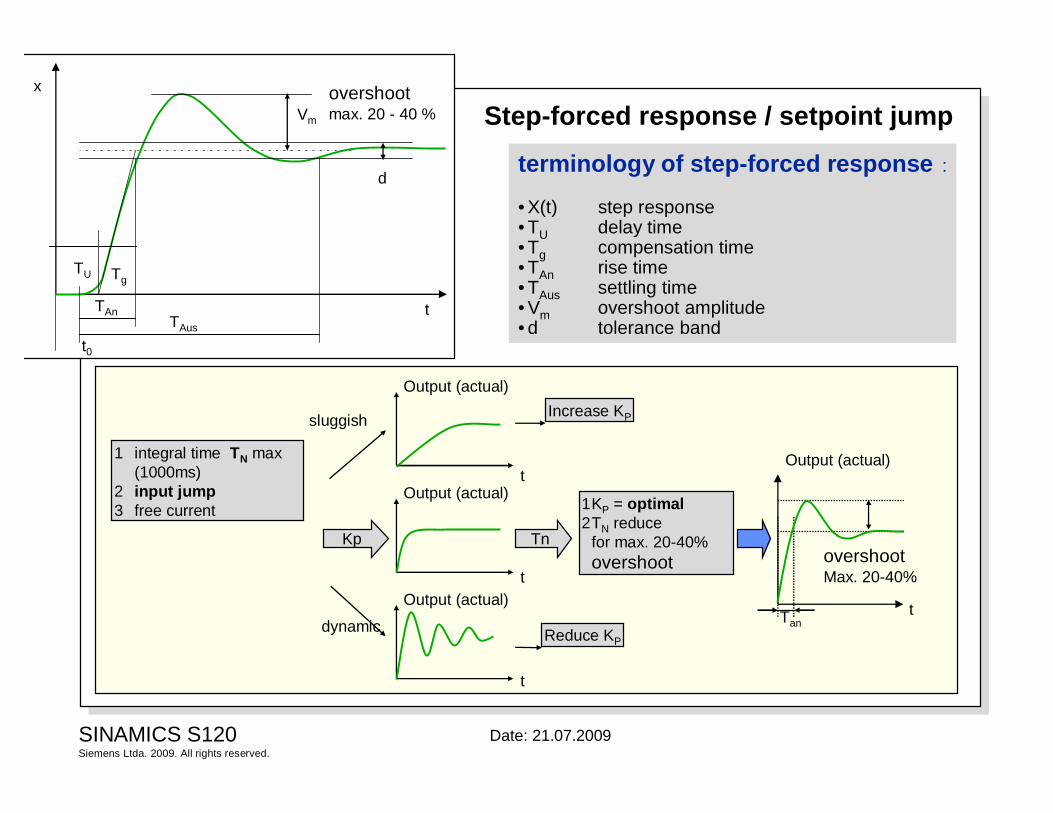
Step-forced response / setpoint jump
terminology of step-forced response :
• X(t) step response• TU delay time• Tg compensation time• TAn rise time• TAus settling time• Vm overshoot amplitude• d tolerance band
t
overshootmax. 20 - 40 %
TU
TAnTAus
Vm
x
t0
Tg
d
t
Output (actual)
1 integral time TN max (1000ms)
2 input jump3 free current
t
Output (actual)
t
Output (actual)
Increase KP
Reduce KP
1KP = optimal2TN reduce
for max. 20-40% overshoot
Kp Tn
sluggish
dynamict
Output (actual)
overshootMax. 20-40%
Tan