SINAMICS S120 Combi ___________________ ___________________ ___________________ ___________________ ___________________ ___________________ ___________________ ___________________ ___________________ ___________________ ___________________ ___________________ ___________________ SINAMICS S120 SINAMICS S120 Combi Manual (GH9), 04/2014 6SL3097-4AV00-0BP4 Fundamental safety instructions 1 System overview 2 Line-side power components 3 S120 Combi Power Modules 4 Topology rules for DRIVE- CLiQ 5 Motor Modules Booksize Compact as expansion axes 6 DC link components 7 Electrically connecting Motor Modules and DC link components 8 Additional system components 9 Encoder system connection 10 Accessories 11 Cabinet design and EMC 12 Service and maintenance 13 Appendix A www.barghmaher.ir

Welcome message from author
This document is posted to help you gain knowledge. Please leave a comment to let me know what you think about it! Share it to your friends and learn new things together.
Transcript
SINAMICS S120 Combi
___________________
___________________
___________________
___________________
___________________
___________________
___________________
___________________
___________________
___________________
___________________
___________________
___________________
SINAMICS
S120 SINAMICS S120 Combi
Manual
(GH9), 04/2014 6SL3097-4AV00-0BP4
Fundamental safety instructions
1
System overview 2
Line-side power components 3
S120 Combi Power Modules 4
Topology rules for DRIVE-CLiQ
5 Motor Modules Booksize Compact as expansion axes
6
DC link components 7
Electrically connecting Motor Modules and DC link components
8
Additional system components
9
Encoder system connection 10
Accessories 11
Cabinet design and EMC 12
Service and maintenance 13
Appendix A
www.barghmaher.ir
Siemens AG Industry Sector Postfach 48 48 90026 NÜRNBERG GERMANY
Order number: 6SL3097-4AV00-0BP4 Ⓟ 03/2014 Subject to change
Copyright © Siemens AG 2010 - 2014. All rights reserved
Legal information Warning notice system
This manual contains notices you have to observe in order to ensure your personal safety, as well as to prevent damage to property. The notices referring to your personal safety are highlighted in the manual by a safety alert symbol, notices referring only to property damage have no safety alert symbol. These notices shown below are graded according to the degree of danger.
DANGER indicates that death or severe personal injury will result if proper precautions are not taken.
WARNING indicates that death or severe personal injury may result if proper precautions are not taken.
CAUTION indicates that minor personal injury can result if proper precautions are not taken.
NOTICE indicates that property damage can result if proper precautions are not taken.
If more than one degree of danger is present, the warning notice representing the highest degree of danger will be used. A notice warning of injury to persons with a safety alert symbol may also include a warning relating to property damage.
Qualified Personnel The product/system described in this documentation may be operated only by personnel qualified for the specific task in accordance with the relevant documentation, in particular its warning notices and safety instructions. Qualified personnel are those who, based on their training and experience, are capable of identifying risks and avoiding potential hazards when working with these products/systems.
Proper use of Siemens products Note the following:
WARNING Siemens products may only be used for the applications described in the catalog and in the relevant technical documentation. If products and components from other manufacturers are used, these must be recommended or approved by Siemens. Proper transport, storage, installation, assembly, commissioning, operation and maintenance are required to ensure that the products operate safely and without any problems. The permissible ambient conditions must be complied with. The information in the relevant documentation must be observed.
Trademarks All names identified by ® are registered trademarks of Siemens AG. The remaining trademarks in this publication may be trademarks whose use by third parties for their own purposes could violate the rights of the owner.
Disclaimer of Liability We have reviewed the contents of this publication to ensure consistency with the hardware and software described. Since variance cannot be precluded entirely, we cannot guarantee full consistency. However, the information in this publication is reviewed regularly and any necessary corrections are included in subsequent editions.
www.barghmaher.ir
SINAMICS S120 Combi Manual, (GH9), 04/2014, 6SL3097-4AV00-0BP4 5
Preface
SINAMICS documentation The SINAMICS documentation is organized in the following categories:
● General documentation / Catalogs
● User documentation
● Manufacturer / Service documentation
More information Using the following link, you can find information on the topics:
● Ordering documentation/overview of documentation
● Additional links to download documents
● Using documentation online (find and search in manuals/information)
http://www.siemens.com/motioncontrol/docu
Please send any questions about the technical documentation (e.g. suggestions for improvement, corrections) to the following e-mail address:
My Documentation Manager Using the following link, you can find information on how to create your own individual documentation based on Siemens' content, and adapt it for your own machine documentation:
http://www.siemens.com/mdm
Training Using the following link, you can find information on SITRAIN - training from Siemens for products, systems and automation engineering solutions:
http://www.siemens.com/sitrain
FAQs You can find Frequently Asked Questions in the Service&Support pages under Product Support.
http://support.automation.siemens.com
www.barghmaher.ir
Preface
SINAMICS S120 Combi 6 Manual, (GH9), 04/2014, 6SL3097-4AV00-0BP4
SINAMICS You can find information on SINAMICS at:
http://www.siemens.com/sinamics.
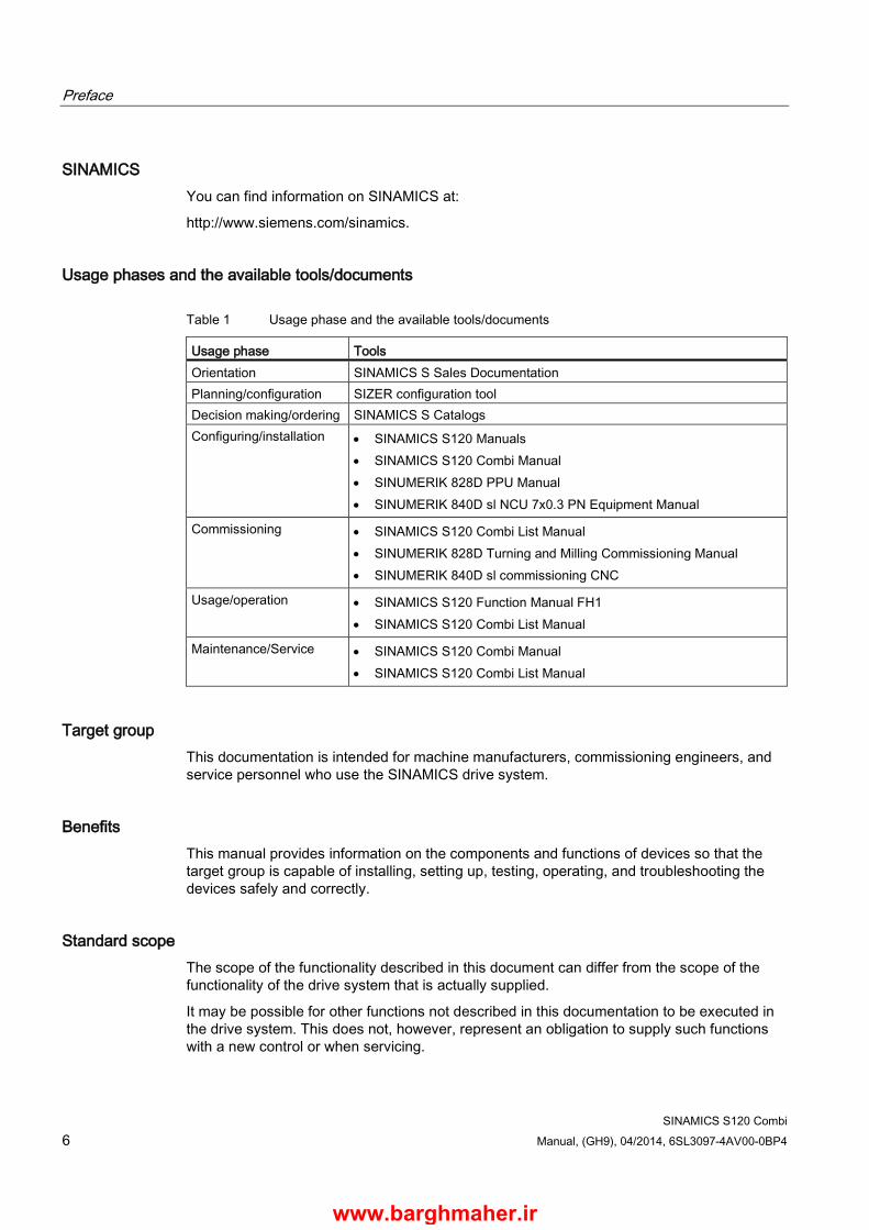
Usage phases and the available tools/documents
Table 1 Usage phase and the available tools/documents
Usage phase Tools Orientation SINAMICS S Sales Documentation Planning/configuration SIZER configuration tool Decision making/ordering SINAMICS S Catalogs Configuring/installation • SINAMICS S120 Manuals
• SINAMICS S120 Combi Manual • SINUMERIK 828D PPU Manual • SINUMERIK 840D sl NCU 7x0.3 PN Equipment Manual
Commissioning • SINAMICS S120 Combi List Manual • SINUMERIK 828D Turning and Milling Commissioning Manual • SINUMERIK 840D sl commissioning CNC
Usage/operation • SINAMICS S120 Function Manual FH1 • SINAMICS S120 Combi List Manual
Maintenance/Service • SINAMICS S120 Combi Manual • SINAMICS S120 Combi List Manual
Target group This documentation is intended for machine manufacturers, commissioning engineers, and service personnel who use the SINAMICS drive system.
Benefits This manual provides information on the components and functions of devices so that the target group is capable of installing, setting up, testing, operating, and troubleshooting the devices safely and correctly.
Standard scope The scope of the functionality described in this document can differ from the scope of the functionality of the drive system that is actually supplied.
It may be possible for other functions not described in this documentation to be executed in the drive system. This does not, however, represent an obligation to supply such functions with a new control or when servicing.
www.barghmaher.ir

Preface
SINAMICS S120 Combi Manual, (GH9), 04/2014, 6SL3097-4AV00-0BP4 7
Functions that are not available in a particular product version of the drive system may be described in the documentation. The functionality of the supplied drive system should only be taken from the ordering documentation.
Extensions or changes made by the machine manufacturer must be documented by the machine manufacturer.
For reasons of clarity, this documentation does not contain all of the detailed information on all of the product types. This documentation cannot take into consideration every conceivable type of installation, operation and service/maintenance.
Technical support Country-specific telephone numbers for technical support are provided in the Internet under Contact:
http://www.siemens.com/automation/service&support
EC Declaration of Conformity and test certifications The EC Declaration of Conformity for the EMC Directive can be found on the Internet at:
http://support.automation.siemens.com/WW/view/de/21901735/134200
The EC Declaration of Conformity for the Low Voltage Directive can be found on the Internet at:
http://support.automation.siemens.com
There – as a search term – enter the number 22383669 .
Test certificates for functional safety functions ("Safety Integrated") can be found at:
http://support.automation.siemens.com
An up-to-date list of currently certified components is also available on request from your local Siemens office. If you have any questions relating to certifications that have not yet been completed, please ask your Siemens contact.
Note General points on product use
Siemens products are only permitted to be used for the applications listed in the catalog and in the associated technical documentation. If third-party products and components are used, then they must be recommended or approved by Siemens.
To ensure trouble-free and safe operation of the products, they must be appropriately transported, stored, assembled, installed, commissioned, operated and maintained. The permissible ambient conditions must be adhered to.
Notes in the associated documentation must be observed.
www.barghmaher.ir
Preface
SINAMICS S120 Combi 8 Manual, (GH9), 04/2014, 6SL3097-4AV00-0BP4
Note
When operated in dry areas, SINAMICS S devices conform to the Low Voltage Directive 73/23/EEC or 2006/95/EEC.
Note
SINAMICS S devices fulfill EMC Directive 89/336/EEC or 2004/108/EEC in the configuration specified in the associated EC Declaration of Conformity for EMC and when the Configuration Manual EMC Installation Guideline, order number 6FC5297-0AD30-0⃞P⃞, is implemented.
Note
The Manual describes a desired state which, if maintained, ensures the required level of operational reliability and compliance with EMC limit values.
Should there be a deviation from the Equipment Manual requirements, appropriate actions (e.g. measurements) must be taken to check/prove that the desired reliable operation is ensured and EMC limit values are complied with.
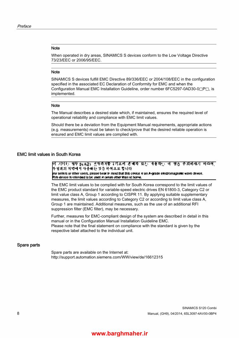
EMC limit values in South Korea
The EMC limit values to be complied with for South Korea correspond to the limit values of the EMC product standard for variable-speed electric drives EN 61800-3, Category C2 or limit value class A, Group 1 according to CISPR 11. By applying suitable supplementary measures, the limit values according to Category C2 or according to limit value class A, Group 1 are maintained. Additional measures, such as the use of an additional RFI suppression filter (EMC filter), may be necessary.
Further, measures for EMC-compliant design of the system are described in detail in this manual or in the Configuration Manual Installation Guideline EMC. Please note that the final statement on compliance with the standard is given by the respective label attached to the individual unit.
Spare parts Spare parts are available on the Internet at: http://support.automation.siemens.com/WW/view/de/16612315
www.barghmaher.ir
Preface
SINAMICS S120 Combi Manual, (GH9), 04/2014, 6SL3097-4AV00-0BP4 9
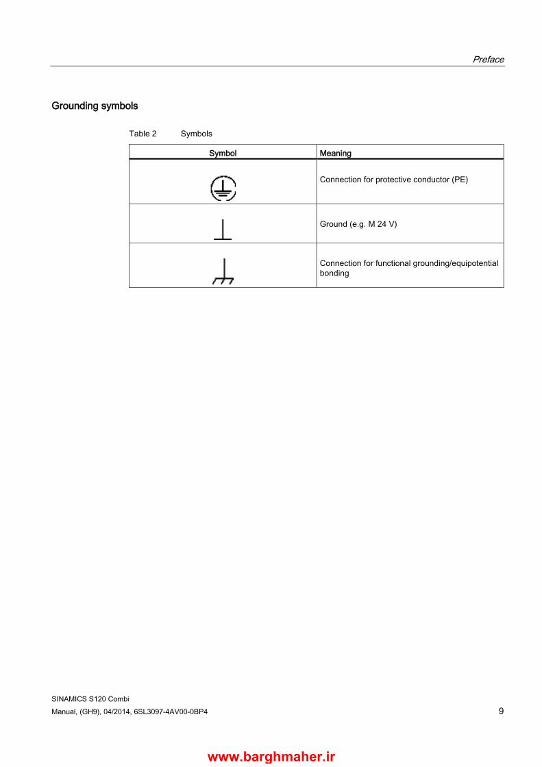
Grounding symbols
Table 2 Symbols
Symbol Meaning
Connection for protective conductor (PE)
Ground (e.g. M 24 V)
Connection for functional grounding/equipotential bonding
www.barghmaher.ir

Preface
SINAMICS S120 Combi 10 Manual, (GH9), 04/2014, 6SL3097-4AV00-0BP4
www.barghmaher.ir
SINAMICS S120 Combi Manual, (GH9), 04/2014, 6SL3097-4AV00-0BP4 11
Table of contents
Preface ................................................................................................................................................... 5
1 Fundamental safety instructions ............................................................................................................ 19
1.1 General safety instructions .......................................................................................................... 19
1.2 Safety instructions for electromagnetic fields (EMF) ................................................................... 22
1.3 Handling electrostatic sensitive devices (ESD) ........................................................................... 23
1.4 Industrial security ......................................................................................................................... 23
1.5 Residual risks of power drive systems ......................................................................................... 24
2 System overview ................................................................................................................................... 27
2.1 SINAMICS S120 Combi components .......................................................................................... 27
2.2 System data ................................................................................................................................. 30
2.3 Derating as a function of the installation altitude and ambient temperature ................................ 32
3 Line-side power components ................................................................................................................. 35
3.1 Introduction .................................................................................................................................. 35
3.2 Information on the disconnector unit ............................................................................................ 36
3.3 Overcurrent protection by means of line fuses and circuit breakers ............................................ 37
3.4 Line supply connection via residual-current devices ................................................................... 38
3.5 Overvoltage protection ................................................................................................................. 40
3.6 Line filters ..................................................................................................................................... 41 3.6.1 Description ................................................................................................................................... 41 3.6.2 Safety information ........................................................................................................................ 41 3.6.3 Interface description ..................................................................................................................... 44 3.6.3.1 Overview ...................................................................................................................................... 44 3.6.3.2 Line/load connection .................................................................................................................... 45 3.6.4 Dimension drawing ...................................................................................................................... 45 3.6.5 Technical data .............................................................................................................................. 46
3.7 Line reactors ................................................................................................................................ 47 3.7.1 Description ................................................................................................................................... 47 3.7.2 Safety information ........................................................................................................................ 47 3.7.3 Connection description ................................................................................................................ 49 3.7.3.1 Overview ...................................................................................................................................... 49 3.7.3.2 Line/load connection .................................................................................................................... 49 3.7.4 Dimension drawings ..................................................................................................................... 50 3.7.5 Technical data .............................................................................................................................. 52
3.8 Line connection versions ............................................................................................................. 53 3.8.1 Ways of connecting the line supply.............................................................................................. 53 3.8.2 Operating line connection components on the line supply .......................................................... 54 3.8.3 Operation of the line connection components via a transformer ................................................. 55
www.barghmaher.ir

Table of contents
SINAMICS S120 Combi 12 Manual, (GH9), 04/2014, 6SL3097-4AV00-0BP4
3.8.3.1 Safety information ....................................................................................................................... 55 3.8.3.2 Line connection conditions .......................................................................................................... 55 3.8.3.3 Dimensioning an isolating transformer/autotransformer for several loads ................................. 56 3.8.3.4 Operating line connection components via an autotransformer ................................................. 60 3.8.3.5 Operating line connection components via an isolating transformer .......................................... 61
4 S120 Combi Power Modules ................................................................................................................. 63
4.1 Introduction.................................................................................................................................. 63 4.1.1 Description .................................................................................................................................. 63 4.1.2 Module versions .......................................................................................................................... 65 4.1.3 Approved controls ....................................................................................................................... 65 4.1.4 Expansion axes that can be connected ...................................................................................... 66
4.2 Safety information ....................................................................................................................... 67
4.3 Interface description .................................................................................................................... 71 4.3.1 Overview diagrams ..................................................................................................................... 71 4.3.2 X1 line connection ....................................................................................................................... 75 4.3.3 X2-X5 motor connection .............................................................................................................. 76 4.3.4 X11 brake connection ................................................................................................................. 77 4.3.5 X12/X13 fan connection .............................................................................................................. 78 4.3.6 X21/X22 EP terminals ................................................................................................................. 79 4.3.7 X200-X205 DRIVE-CLiQ interfaces ............................................................................................ 81 4.3.8 X220 TTL encoder ...................................................................................................................... 83 4.3.9 X224 24 V connector ................................................................................................................... 86
4.4 Connection examples .................................................................................................................. 87
4.5 Meaning of the LEDs on the S120 Combi ................................................................................... 90
4.6 Dimension drawings .................................................................................................................... 92
4.7 Installation ................................................................................................................................... 93 4.7.1 Drilling patterns and installation cut-outs .................................................................................... 93 4.7.2 Installing the reinforcement plates .............................................................................................. 95 4.7.2.1 Description .................................................................................................................................. 95 4.7.2.2 Installation ................................................................................................................................... 96 4.7.2.3 Technical data ............................................................................................................................. 99 4.7.3 Installing an S120 Combi Power Module .................................................................................. 100 4.7.4 Assembling a drip protection grid .............................................................................................. 102 4.7.5 Mounting an external fan module .............................................................................................. 103 4.7.5.1 Description ................................................................................................................................ 103 4.7.5.2 Overview ................................................................................................................................... 103 4.7.5.3 Dimension drawing .................................................................................................................... 105 4.7.5.4 Installation ................................................................................................................................. 106 4.7.5.5 Technical data ........................................................................................................................... 109
4.8 Electrical connection ................................................................................................................. 110 4.8.1 Stripped length for the line supply and power cables ............................................................... 110 4.8.2 Line supply cable ...................................................................................................................... 112 4.8.3 Power cables for motors ........................................................................................................... 113 4.8.4 Signal cables at the EP terminals ............................................................................................. 114
4.9 Technical data ........................................................................................................................... 115 4.9.1 Characteristic curves ................................................................................................................. 120 4.9.1.1 Derating characteristics ............................................................................................................. 126
www.barghmaher.ir
Table of contents
SINAMICS S120 Combi Manual, (GH9), 04/2014, 6SL3097-4AV00-0BP4 13
5 Topology rules for DRIVE-CLiQ........................................................................................................... 127
5.1 Connection examples ................................................................................................................ 130 5.1.1 Operation with a 3 axes Power Module ..................................................................................... 130 5.1.2 Operation with a 4 axes Power Module ..................................................................................... 132
6 Motor Modules Booksize Compact as expansion axes ........................................................................ 135
6.1 Description ................................................................................................................................. 135
6.2 Safety information ...................................................................................................................... 136
6.3 Interface description ................................................................................................................... 139 6.3.1 Overview .................................................................................................................................... 139 6.3.2 X1/X2 motor connection ............................................................................................................. 141 6.3.3 X11/X12 motor brake connection ............................................................................................... 142 6.3.4 X21/X22 EP terminals / temperature sensor Motor Module ...................................................... 143 6.3.5 X200-X203 DRIVE-CLiQ interface ............................................................................................. 144
6.4 Connection example .................................................................................................................. 145
6.5 Meaning of the LEDs on the Motor Module Booksize Compact ................................................ 146
6.6 Dimension drawings ................................................................................................................... 147
6.7 Installation .................................................................................................................................. 150
6.8 Technical data ............................................................................................................................ 151 6.8.1 Characteristics ........................................................................................................................... 153
7 DC link components ............................................................................................................................ 157
7.1 Control Supply Module CSM ...................................................................................................... 157 7.1.1 Description ................................................................................................................................. 157 7.1.2 Safety information ...................................................................................................................... 158 7.1.3 Interface description ................................................................................................................... 160 7.1.3.1 Overview .................................................................................................................................... 160 7.1.3.2 X1 line connection ...................................................................................................................... 161 7.1.3.3 X21 signaling contact ................................................................................................................. 162 7.1.3.4 X24 24 V terminal adapter ......................................................................................................... 162 7.1.3.5 S1 DIP switch ............................................................................................................................. 163 7.1.4 Connection example .................................................................................................................. 164 7.1.5 Meaning of the LEDs on the Control Supply Module ................................................................. 166 7.1.6 Dimension drawing .................................................................................................................... 167 7.1.7 Installation .................................................................................................................................. 168 7.1.8 Technical data ............................................................................................................................ 169 7.1.8.1 Characteristics ........................................................................................................................... 170
7.2 Braking Module Booksize .......................................................................................................... 171 7.2.1 Description ................................................................................................................................. 171 7.2.2 Safety information ...................................................................................................................... 173 7.2.3 Interface description ................................................................................................................... 175 7.2.3.1 Overview .................................................................................................................................... 175 7.2.3.2 X1 braking resistor connection ................................................................................................... 176 7.2.3.3 X21 digital inputs/outputs ........................................................................................................... 177 7.2.4 Connection example .................................................................................................................. 178 7.2.5 Meaning of the LEDs ................................................................................................................. 179 7.2.6 Dimension drawing .................................................................................................................... 180 7.2.7 Installation .................................................................................................................................. 181
www.barghmaher.ir
Table of contents
SINAMICS S120 Combi 14 Manual, (GH9), 04/2014, 6SL3097-4AV00-0BP4
7.2.8 Technical data ........................................................................................................................... 182 7.2.8.1 Characteristic curves ................................................................................................................. 182
7.3 Braking resistors ....................................................................................................................... 184 7.3.1 Description ................................................................................................................................ 184 7.3.2 Safety information ..................................................................................................................... 185 7.3.3 Dimension drawings .................................................................................................................. 186 7.3.4 Technical data ........................................................................................................................... 188
8 Electrically connecting Motor Modules and DC link components ........................................................... 189
8.1 Introduction................................................................................................................................ 189
8.2 Removing the front cover and opening the DC link cover on the S120 Combi ........................ 190
8.3 Connection of DC link busbars and 24 V busbars .................................................................... 192
8.4 Connecting an additional component ........................................................................................ 195
9 Additional system components ............................................................................................................. 197
9.1 Terminal Module TM54F ........................................................................................................... 197 9.1.1 Description ................................................................................................................................ 197 9.1.2 Safety information ..................................................................................................................... 198 9.1.3 Interface description .................................................................................................................. 199 9.1.3.1 Overview ................................................................................................................................... 199 9.1.3.2 X500/X501 DRIVE-CLiQ interfaces .......................................................................................... 200 9.1.3.3 X514 power supply for digital outputs and sensors .................................................................. 200 9.1.3.4 X520 sensor power supply ........................................................................................................ 201 9.1.3.5 X521 fail-safe digital inputs + power supply with forced dormant error detection .................... 201 9.1.3.6 X522 fail-safe digital inputs ....................................................................................................... 202 9.1.3.7 X523 fail-safe digital output ....................................................................................................... 203 9.1.3.8 X524 Electronics power supply ................................................................................................. 204 9.1.3.9 X525 fail-safe digital output ....................................................................................................... 205 9.1.3.10 X531 fail-safe digital inputs + power supply with forced dormant error detection .................... 206 9.1.3.11 X532 fail-safe digital inputs ....................................................................................................... 207 9.1.3.12 X533 fail-safe digital output ....................................................................................................... 208 9.1.3.13 X535 fail-safe digital output ....................................................................................................... 209 9.1.4 Connection example ................................................................................................................. 210 9.1.5 Meaning of LEDs ....................................................................................................................... 211 9.1.6 Dimension drawing .................................................................................................................... 213 9.1.7 Installation ................................................................................................................................. 214 9.1.8 Protective conductor connection and shield support ................................................................ 215 9.1.9 Technical data ........................................................................................................................... 216
9.2 DRIVE-CLiQ Hub Module DMC20 ............................................................................................ 217 9.2.1 Description ................................................................................................................................ 217 9.2.2 Safety information ..................................................................................................................... 217 9.2.3 Interface description .................................................................................................................. 219 9.2.3.1 Overview ................................................................................................................................... 219 9.2.3.2 X524 Electronics power supply ................................................................................................. 220 9.2.3.3 X500-X505 DRIVE-CLiQ interfaces .......................................................................................... 221 9.2.3.4 Meaning of the LED on the DMC20 .......................................................................................... 222 9.2.4 Dimension drawing .................................................................................................................... 223 9.2.5 Installation ................................................................................................................................. 224 9.2.6 Technical data ........................................................................................................................... 225
www.barghmaher.ir

Table of contents
SINAMICS S120 Combi Manual, (GH9), 04/2014, 6SL3097-4AV00-0BP4 15
9.3 DRIVE-CLiQ Hub Module External DME20 ............................................................................... 226 9.3.1 Description ................................................................................................................................. 226 9.3.2 Safety information ...................................................................................................................... 226 9.3.3 Interface description ................................................................................................................... 227 9.3.3.1 Overview .................................................................................................................................... 227 9.3.3.2 X500-X505 DRIVE-CLiQ interfaces ........................................................................................... 228 9.3.3.3 X524 Electronics power supply .................................................................................................. 229 9.3.4 Dimension drawing .................................................................................................................... 231 9.3.5 Installation .................................................................................................................................. 232 9.3.6 Technical data ............................................................................................................................ 233 9.3.7 Specifications for use with UL approval ..................................................................................... 233
10 Encoder system connection ................................................................................................................ 235
10.1 Sensor Module Cabinet-Mounted SMC20 ................................................................................. 235 10.1.1 Description ................................................................................................................................. 235 10.1.2 Product-specific safety instructions............................................................................................ 235 10.1.3 Interface description ................................................................................................................... 237 10.1.3.1 Overview .................................................................................................................................... 237 10.1.3.2 X500 DRIVE-CLiQ interface ...................................................................................................... 238 10.1.3.3 X520 encoder system interface ................................................................................................. 239 10.1.3.4 X524 Electronics power supply .................................................................................................. 240 10.1.3.5 Meaning of the LED on the Sensor Module Cabinet-Mounted SMC20 ..................................... 241 10.1.4 Dimension drawing .................................................................................................................... 242 10.1.5 Mounting .................................................................................................................................... 243 10.1.6 Technical data ............................................................................................................................ 244
10.2 Sensor Module Cabinet-Mounted SMC30 ................................................................................. 245 10.2.1 Description ................................................................................................................................. 245 10.2.2 Interface description ................................................................................................................... 246 10.2.2.1 Overview .................................................................................................................................... 246 10.2.2.2 X500 DRIVE-CLiQ interface ...................................................................................................... 247 10.2.2.3 X520 encoder system interface ................................................................................................. 248 10.2.2.4 X521 / X531 alternative encoder system interface .................................................................... 250 10.2.2.5 X524 Electronics power supply .................................................................................................. 252 10.2.3 Meaning of the LEDs ................................................................................................................. 253 10.2.3.1 Meaning of LEDs on the Sensor Module Cabinet-Mounted SMC30 ......................................... 253 10.2.3.2 Cause and rectification of faults ................................................................................................. 254 10.2.4 Dimension drawing .................................................................................................................... 254 10.2.5 Mounting .................................................................................................................................... 255 10.2.6 Protective conductor connection and shield support ................................................................. 256 10.2.7 Technical data ............................................................................................................................ 257
10.3 Sensor Module External SME20 ................................................................................................ 263 10.3.1 Description ................................................................................................................................. 263 10.3.2 Safety Information ...................................................................................................................... 263 10.3.3 Interface description ................................................................................................................... 264 10.3.3.1 Overview .................................................................................................................................... 264 10.3.3.2 Connection example .................................................................................................................. 264 10.3.3.3 DRIVE-CLiQ interface ................................................................................................................ 265 10.3.3.4 Encoder system interface .......................................................................................................... 266 10.3.4 Dimension drawing .................................................................................................................... 267 10.3.5 Installation .................................................................................................................................. 268 10.3.6 Technical data ............................................................................................................................ 269
www.barghmaher.ir

Table of contents
SINAMICS S120 Combi 16 Manual, (GH9), 04/2014, 6SL3097-4AV00-0BP4
10.4 Sensor Module External SME25 ............................................................................................... 271 10.4.1 Description ................................................................................................................................ 271 10.4.2 Interface description .................................................................................................................. 271 10.4.2.1 Overview ................................................................................................................................... 271 10.4.2.2 Connection example ................................................................................................................. 271 10.4.2.3 DRIVE-CLiQ interface ............................................................................................................... 272 10.4.2.4 Encoder system interface .......................................................................................................... 273 10.4.3 Dimension drawing .................................................................................................................... 274 10.4.4 Installation ................................................................................................................................. 275 10.4.5 Technical data ........................................................................................................................... 276
11 Accessories ......................................................................................................................................... 279
11.1 DRIVE-CLiQ cabinet bushing ................................................................................................... 279 11.1.1 Description ................................................................................................................................ 279 11.1.2 Interface description .................................................................................................................. 280 11.1.2.1 Overview ................................................................................................................................... 280 11.1.3 Dimension drawings .................................................................................................................. 281 11.1.4 DRIVE-CLiQ cabinet bushing for cables with DRIVE-CLiQ connectors ................................... 282 11.1.5 Technical data ........................................................................................................................... 284
11.2 DRIVE-CLiQ coupling ............................................................................................................... 285 11.2.1 Description ................................................................................................................................ 285 11.2.2 Safety information ..................................................................................................................... 285 11.2.3 Interface description .................................................................................................................. 286 11.2.3.1 Overview ................................................................................................................................... 286 11.2.4 Dimension drawing .................................................................................................................... 286 11.2.5 Mounting.................................................................................................................................... 287 11.2.6 Technical data ........................................................................................................................... 287
12 Cabinet design and EMC ..................................................................................................................... 289
12.1 General information ................................................................................................................... 289
12.2 Safety information ..................................................................................................................... 290
12.3 Directives................................................................................................................................... 291
12.4 Notes on electromagnetic compatibility (EMC) ......................................................................... 292
12.5 Cable shielding and routing....................................................................................................... 293
12.6 24 V DC supply ......................................................................................................................... 295 12.6.1 General information ................................................................................................................... 295 12.6.2 24 V power supply and connection of components .................................................................. 297 12.6.3 Overcurrent protection in the 24 V solid-state circuit ................................................................ 299 12.6.4 Typical 24 V current consumption of the components .............................................................. 300 12.6.5 Selecting power supply units .................................................................................................... 302
12.7 Connection system .................................................................................................................... 303 12.7.1 DRIVE-CLiQ signal cables ........................................................................................................ 303 12.7.2 Power cables for motors ........................................................................................................... 304 12.7.2.1 Approved power cables ............................................................................................................. 304 12.7.3 Current-carrying capacity and derating factors for power cables and signal cables ................ 307 12.7.4 Connectable conductor cross-sections for spring-loaded terminals ......................................... 308 12.7.5 Connectable conductor cross-sections for screw terminals ...................................................... 309
12.8 Protective connection and equipotential bonding ..................................................................... 311
www.barghmaher.ir
Table of contents
SINAMICS S120 Combi Manual, (GH9), 04/2014, 6SL3097-4AV00-0BP4 17
12.9 Note on control cabinet cooling.................................................................................................. 312 12.9.1 General information ................................................................................................................... 312 12.9.2 Ventilation .................................................................................................................................. 315 12.9.3 Dimensioning Climate Control Equipment ................................................................................. 317 12.9.4 Power loss of components in rated operation ............................................................................ 318 12.9.4.1 General information ................................................................................................................... 318 12.9.4.2 Power losses for SINUMERIK control systems, DC link components and supplementary
system components ................................................................................................................... 318 12.9.4.3 Power losses for S120 Combi Power Modules .......................................................................... 319 12.9.4.4 Power loss for line filters and line reactors ................................................................................ 319 12.9.4.5 Electronics losses of power units ............................................................................................... 320 12.9.4.6 Losses in partial-load operation ................................................................................................. 321
13 Service and maintenance .................................................................................................................... 323
13.1 Technical Support ...................................................................................................................... 323
13.2 Spare parts ................................................................................................................................. 324
13.3 Replacing the fan ....................................................................................................................... 325 13.3.1 Safety instructions when replacing a fan ................................................................................... 325 13.3.2 Replacing the Internal fan on the S120 Combi Power Module .................................................. 326 13.3.3 Replacing the fan on the Motor Modules Booksize Compact .................................................... 329 13.3.4 Replacing the fan on the Control Supply Module ...................................................................... 332
13.4 Cleaning the S120 Combi heat sink........................................................................................... 334
13.5 Forming the DC link capacitors .................................................................................................. 336
13.6 Installing seals on the S120 Combi............................................................................................ 338
13.7 Recycling and disposal .............................................................................................................. 340
A Appendix............................................................................................................................................. 341
A.1 List of abbreviations ................................................................................................................... 341
A.2 Documentation overview ............................................................................................................ 350
Index................................................................................................................................................... 351
www.barghmaher.ir

Table of contents
SINAMICS S120 Combi 18 Manual, (GH9), 04/2014, 6SL3097-4AV00-0BP4
www.barghmaher.ir
SINAMICS S120 Combi Manual, (GH9), 04/2014, 6SL3097-4AV00-0BP4 19
Fundamental safety instructions 1 1.1 General safety instructions
DANGER
Danger to life due to live parts and other energy sources
Death or serious injury can result when live parts are touched. • Only work on electrical devices when you are qualified for this job. • Always observe the country-specific safety rules.
Generally, six steps apply when establishing safety: 1. Prepare for shutdown and notify all those who will be affected by the procedure. 2. Disconnect the machine from the supply.
– Switch off the machine. – Wait until the discharge time specified on the warning labels has elapsed. – Check that it really is in a no-voltage condition, from phase conductor to phase
conductor and phase conductor to protective conductor. – Check whether the existing auxiliary supply circuits are de-energized. – Ensure that the motors cannot move.
3. Identify all other dangerous energy sources, e.g. compressed air, hydraulic systems, or water.
4. Isolate or neutralize all hazardous energy sources by closing switches, grounding or short-circuiting or closing valves, for example.
5. Secure the energy sources against switching on again. 6. Ensure that the correct machine is completely interlocked.
After you have completed the work, restore the operational readiness in the inverse sequence.
WARNING
Danger to life through a hazardous voltage when connecting an unsuitable power supply
Touching live components can result in death or severe injury. • Only use power supplies that provide SELV (Safety Extra Low Voltage) or PELV-
(Protective Extra Low Voltage) output voltages for all connections and terminals of the electronics modules.
www.barghmaher.ir
Fundamental safety instructions 1.1 Residual risks of power drive systems
SINAMICS S120 Combi 20 Manual, (GH9), 04/2014, 6SL3097-4AV00-0BP4
WARNING
Danger to life when live parts are touched on damaged devices
Improper handling of devices can cause damage.
For damaged devices, hazardous voltages can be present at the enclosure or at exposed components; if touched, this can result in death or severe injury. • Ensure compliance with the limit values specified in the technical data during transport,
storage and operation. • Do not use any damaged devices.
WARNING
Danger to life through electric shock due to unconnected cable shields
Hazardous touch voltages can occur through capacitive cross-coupling due to unconnected cable shields. • As a minimum, connect cable shields and the conductors of power cables that are not
used (e.g. brake cores) at one end at the grounded housing potential.
WARNING
Danger to life due to electric shock when not grounded
For missing or incorrectly implemented protective conductor connection for devices with protection class I, high voltages can be present at open, exposed parts, which when touched, can result in death or severe injury. • Ground the device in compliance with the applicable regulations.
WARNING
Danger to life due to electric shock when opening plug connections in operation
When opening plug connections in operation, arcs can result in severe injury or death. • Only open plug connections when the equipment is in a no-voltage state, unless it has
been explicitly stated that they can be opened in operation.
WARNING
Danger to life due to fire spreading if housing is inadequate
Fire and smoke development can cause severe personal injury or material damage. • Install devices without a protective housing in a metal control cabinet (or protect the
device by another equivalent measure) in such a way that contact with fire is prevented. • Ensure that smoke can only escape via controlled and monitored paths.
www.barghmaher.ir

Fundamental safety instructions 1.1 Residual risks of power drive systems
SINAMICS S120 Combi Manual, (GH9), 04/2014, 6SL3097-4AV00-0BP4 21
WARNING
Danger to life through unexpected movement of machines when using mobile wireless devices or mobile phones
Using mobile wireless devices or mobile phones with a transmit power > 1 W closer than approx. 2 m to the components may cause the devices to malfunction, influence the functional safety of machines therefore putting people at risk or causing material damage. • Switch the wireless devices or mobile phones off in the immediate vicinity of the
components.
WARNING
Danger to life due to the motor catching fire in the event of insulation overload
There is higher stress on the motor insulation through a ground fault in an IT system. If the insulation fails, it is possible that death or severe injury can occur as a result of smoke and fire. • Use a monitoring device that signals an insulation fault. • Correct the fault as quickly as possible so the motor insulation is not overloaded.
WARNING
Danger to life due to fire if overheating occurs because of insufficient ventilation clearances
Inadequate ventilation clearances can cause overheating of components with subsequent fire and smoke. This can cause severe injury or even death. This can also result in increased downtime and reduced service lives for devices/systems. • Ensure compliance with the specified minimum clearance as ventilation clearance for
the respective component.
WARNING
Danger of an accident occurring due to missing or illegible warning labels
Missing or illegible warning labels can result in accidents involving death or serious injury. • Check that the warning labels are complete based on the documentation. • Attach any missing warning labels to the components, in the national language if
necessary. • Replace illegible warning labels.
www.barghmaher.ir
Fundamental safety instructions 1.2 Residual risks of power drive systems
SINAMICS S120 Combi 22 Manual, (GH9), 04/2014, 6SL3097-4AV00-0BP4
NOTICE
Device damage caused by incorrect voltage/insulation tests
Incorrect voltage/insulation tests can damage the device. • Before carrying out a voltage/insulation check of the system/machine, disconnect the
devices as all converters and motors have been subject to a high voltage test by the manufacturer, and therefore it is not necessary to perform an additional test within the system/machine.
WARNING
Danger to life when safety functions are inactive
Safety functions that are inactive or that have not been adjusted accordingly can cause operational faults on machines that could lead to serious injury or death. • Observe the information in the appropriate product documentation before
commissioning. • Carry out a safety inspection for functions relevant to safety on the entire system,
including all safety-related components. • Ensure that the safety functions used in your drives and automation tasks are adjusted
and activated through appropriate parameterizing. • Perform a function test. • Only put your plant into live operation once you have guaranteed that the functions
relevant to safety are running correctly.
Note Important safety notices for safety functions
If you want to use safety functions, you must observe the safety notices in the safety manuals.
1.2 Safety instructions for electromagnetic fields (EMF)
WARNING
Danger to life from electromagnetic fields
Electromagnetic fields (EMF) are generated by the operation of electrical power equipment such as transformers, converters or motors.
People with pacemakers or implants are at a special risk in the immediate vicinity of these devices/systems. • Ensure that the persons involved are the necessary distance away (minimum 2 m).
www.barghmaher.ir

Fundamental safety instructions 1.3 Residual risks of power drive systems
SINAMICS S120 Combi Manual, (GH9), 04/2014, 6SL3097-4AV00-0BP4 23
1.3 Handling electrostatic sensitive devices (ESD) Electrostatic sensitive devices (ESD) are individual components, integrated circuits, modules or devices that may be damaged by either electric fields or electrostatic discharge.
NOTICE
Damage through electric fields or electrostatic discharge
Electric fields or electrostatic discharge can cause malfunctions through damaged individual components, integrated circuits, modules or devices. • Only pack, store, transport and send electronic components, modules or devices in their
original packaging or in other suitable materials, e.g conductive foam rubber of aluminum foil.
• Only touch components, modules and devices when you are grounded by one of the following methods: – Wearing an ESD wrist strap – Wearing ESD shoes or ESD grounding straps in ESD areas with conductive flooring
• Only place electronic components, modules or devices on conductive surfaces (table with ESD surface, conductive ESD foam, ESD packaging, ESD transport container).
1.4 Industrial security
Note Industrial security
Siemens provides automation and drive products with industrial security functions that support the secure operation of plants or machines. They are an important component in a holistic industrial security concept. With this in mind, our products undergo continuous development. We therefore recommend that you keep yourself informed with the latest information and updates of our product.
Information and newsletters can be found at:
http://support.automation.siemens.com
To ensure the secure operation of a plant or machine, it is also necessary to take suitable preventive action (e.g. cell protection concept) and to integrate the automation and drive components into a state-of-the-art holistic industrial security concept for the entire plant or machine. Any third-party products used must also be taken into account.
For more detailed information, go to:
http://www.siemens.com/industrialsecurity
www.barghmaher.ir

Fundamental safety instructions 1.5 Residual risks of power drive systems
SINAMICS S120 Combi 24 Manual, (GH9), 04/2014, 6SL3097-4AV00-0BP4
WARNING
Danger as a result of unsafe operating states resulting from software manipulation
Software manipulation (e.g. by viruses, Trojan horses, malware, worms) can cause unsafe operating states to develop in your installation which can lead to death, severe injuries and/or material damage. • Keep the software up to date.
Information and newsletters can be found at: http://support.automation.siemens.com
• Incorporate the automation and drive components into a state-of-the-art, integrated industrial security concept for the installation or machine. For more detailed information, go to: http://www.siemens.com/industrialsecurity
• Make sure that you include all installed products into the integrated industrial security concept.
1.5 Residual risks of power drive systems The control and drive components of a drive system are approved for industrial and commercial use in industrial line supplies. Their use in public line supplies requires a different configuration and/or additional measures.
These components may only be operated in closed housings or in higher-level control cabinets with protective covers that are closed, and when all of the protective devices are used.
These components may only be handled by qualified and trained technical personnel who are knowledgeable and observe all of the safety instructions on the components and in the associated technical user documentation.
When assessing the machine's risk in accordance with the respective local regulations (e.g., EC Machinery Directive), the machine manufacturer must take into account the following residual risks emanating from the control and drive components of a drive system:
1. Unintentional movements of driven machine components during commissioning, operation, maintenance, and repairs caused by, for example:
– Hardware defects and/or software errors in the sensors, controllers, actuators, and connection technology
– Response times of the controller and drive
– Operating and/or ambient conditions outside of the specification
– Condensation / conductive contamination
– Parameterization, programming, cabling, and installation errors
– Use of radio devices / cellular phones in the immediate vicinity of the controller
– External influences / damage
www.barghmaher.ir

Fundamental safety instructions 1.5 Residual risks of power drive systems
SINAMICS S120 Combi Manual, (GH9), 04/2014, 6SL3097-4AV00-0BP4 25
2. In the event of a fault, exceptionally high temperatures, including an open fire, as well as emissions of light, noise, particles, gases, etc. can occur inside and outside the inverter, e.g.:
– Component malfunctions
– Software errors
– Operating and/or ambient conditions outside of the specification
– External influences / damage
Inverters of the Open Type / IP20 degree of protection must be installed in a metal control cabinet (or protected by another equivalent measure) such that the contact with fire inside and outside the inverter is not possible.
3. Hazardous shock voltages caused by, for example:
– Component malfunctions
– Influence of electrostatic charging
– Induction of voltages in moving motors
– Operating and/or ambient conditions outside of the specification
– Condensation / conductive contamination
– External influences / damage
4. Electrical, magnetic and electromagnetic fields generated in operation that can pose a risk to people with a pacemaker, implants or metal replacement joints, etc. if they are too close.
5. Release of environmental pollutants or emissions as a result of improper operation of the system and/or failure to dispose of components safely and correctly.
Note
The components must be protected against conductive contamination (e.g. by installing them in a control cabinet with degree of protection IP54 according to IEC 60529 or NEMA 12).
Assuming that conductive contamination at the installation site can definitely be excluded, a lower degree of cabinet protection may be permitted.
For more information about residual risks of the components in a drive system, see the relevant sections in the technical user documentation.
www.barghmaher.ir

Fundamental safety instructions 1.5 Residual risks of power drive systems
SINAMICS S120 Combi 26 Manual, (GH9), 04/2014, 6SL3097-4AV00-0BP4
www.barghmaher.ir
SINAMICS S120 Combi Manual, (GH9), 04/2014, 6SL3097-4AV00-0BP4 27
System overview 2 2.1 SINAMICS S120 Combi components
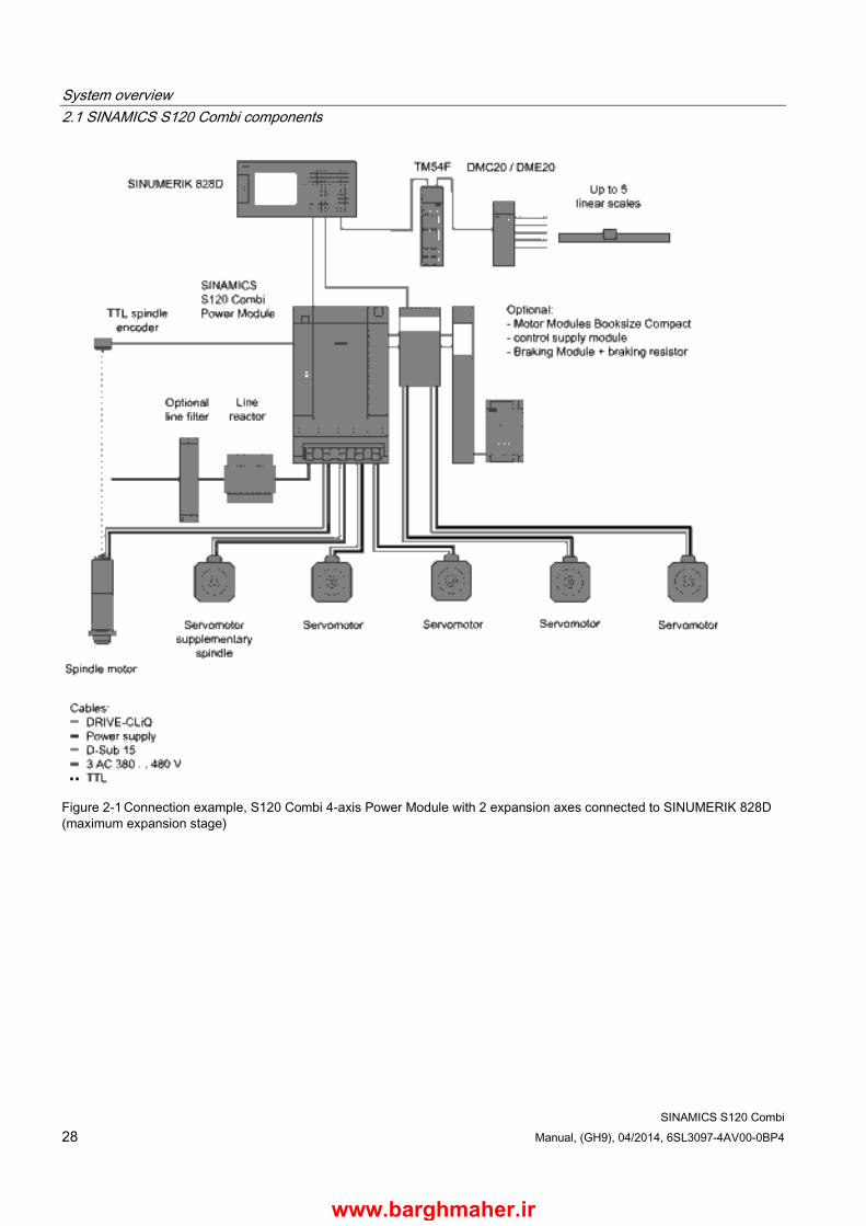
System components ● Line-side power components such as fuses and contactors to switch the energy supply
● Reactors and filters to maintain EMC regulations
● Motor Modules for 1 - 2 expansion axes which function as inverters and provide the energy to the connected motors
● DC link components (Braking Module, Control Supply Module) used optionally for stabilizing the DC link voltage
● Additional system components and encoder system connections to expand the functionality and to handle various interfaces for encoders and process signals.
The SINAMICS S120 Combi is intended for installation in a control cabinet. It sets itself apart as a result of the following properties:
● Easy to handle, simple installation and wiring
● Practical connection system, cable routing in accordance with EMC requirements
● Standardized design, side-by-side mounting
Application and cooling method The S120 Combi Power Modules are optimized as a drive for processing machines with 3 to 6 axes. The Power Modules are available with the "external air cooling" cooling method.
Motor Modules in the booksize compact format are used as expansion axes.
www.barghmaher.ir
System overview 2.1 SINAMICS S120 Combi components
SINAMICS S120 Combi 28 Manual, (GH9), 04/2014, 6SL3097-4AV00-0BP4
Figure 2-1 Connection example, S120 Combi 4-axis Power Module with 2 expansion axes connected to SINUMERIK 828D (maximum expansion stage)
www.barghmaher.ir

System overview 2.1 SINAMICS S120 Combi components
SINAMICS S120 Combi Manual, (GH9), 04/2014, 6SL3097-4AV00-0BP4 29
Figure 2-2 Connection example, S120 Combi 4-axis Power Module with 2 expansion axes connected to SINUMERIK 840D sl (maximum expansion stage)
www.barghmaher.ir

System overview 2.2 System data
SINAMICS S120 Combi 30 Manual, (GH9), 04/2014, 6SL3097-4AV00-0BP4
2.2 System data
Technical data
The following technical data apply for SINAMICS S120 Combi Power Modules.
Table 2- 1 Electrical data
Line connection voltage 3 AC 380 V - 10 % … 3 AC 480 V + 10 % Above an installation altitude of 2000 m, an isolating transformer must be used (see Chapter Derating as a function of the installation altitude and ambient temperature (Page 32)).
Line frequency 45 Hz … 66 Hz Line supply types TN, TT, and IT line supplies Electronics power supply 24 V DC 15/20 % 1),
Safety extra-low voltage PELV or SELV (see Chapter 24 V DC supply (Page 295))
Rated short-circuit current SCCR according to UL508C 65 kA Radio interference suppression acc. to EN 61800-3 Category C2
for plant and system versions in conformance with the documentation
Overvoltage category III Pollution degree 2 1) If a motor holding brake is used, restricted voltage tolerances (24 V ± 10 %) may have to be taken into account.
Table 2- 2 Environmental conditions
Degree of protection IPXXB acc. to EN 60529, open type according to UL508
Protection class, line supply circuits Electronic circuits
I (with protective conductor connection) safety extra-low voltage PELV / SELV
Permissible cooling medium temperature (air) and installation altitude in operation
0°C to +45°C up to an installation altitude of 1000 m without derating, installation altitude >1000 m up to 4000 m, see the derating characteristic (Page 126) with respect to the installation altitude or reduction of the ambient temperature by 3.5 K per 500 m.
Chemically active substances Long-term storage in the transport packaging Class 1C2 according to EN 60721-3-1 Transport in the transport packaging Class 2C2 according to EN 60721-3-2 Operation Class 3C2 according to EN 60721-3-3 Biological environmental conditions Long-term storage in the transport packaging Class 1B1 according to EN 60721-3-1 Transport in the transport packaging Class 2B1 according to EN 60721-3-2 Operation Class 3B1 according to EN 60721-3-3
www.barghmaher.ir
System overview 2.2 System data
SINAMICS S120 Combi Manual, (GH9), 04/2014, 6SL3097-4AV00-0BP4 31
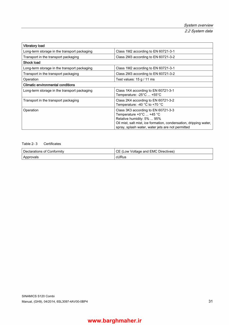
Vibratory load Long-term storage in the transport packaging Class 1M2 according to EN 60721-3-1 Transport in the transport packaging Class 2M3 according to EN 60721-3-2 Shock load Long-term storage in the transport packaging Class 1M2 according to EN 60721-3-1 Transport in the transport packaging Class 2M3 according to EN 60721-3-2 Operation Test values: 15 g / 11 ms Climatic environmental conditions Long-term storage in the transport packaging Class 1K4 according to EN 60721-3-1
Temperature: -25°C ... +55°C Transport in the transport packaging Class 2K4 according to EN 60721-3-2
Temperature: -40 °C to +70 °C Operation Class 3K3 according to EN 60721-3-3
Temperature +0°C ... +45 °C Relative humidity: 5% ... 95% Oil mist, salt mist, ice formation, condensation, dripping water, spray, splash water, water jets are not permitted
Table 2- 3 Certificates
Declarations of Conformity CE (Low Voltage and EMC Directives) Approvals cURus
www.barghmaher.ir
System overview 2.3 Derating as a function of the installation altitude and ambient temperature
SINAMICS S120 Combi 32 Manual, (GH9), 04/2014, 6SL3097-4AV00-0BP4
2.3 Derating as a function of the installation altitude and ambient temperature
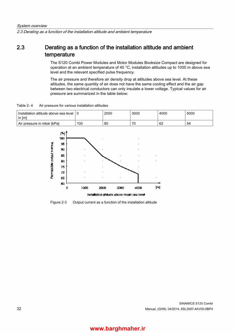
The S120 Combi Power Modules and Motor Modules Booksize Compact are designed for operation at an ambient temperature of 40 °C, installation altitudes up to 1000 m above sea level and the relevant specified pulse frequency.
The air pressure and therefore air density drop at altitudes above sea level. At these altitudes, the same quantity of air does not have the same cooling effect and the air gap between two electrical conductors can only insulate a lower voltage. Typical values for air pressure are summarized in the table below:
Table 2- 4 Air pressure for various installation altitudes
Installation altitude above sea level in [m]
0 2000 3000 4000 5000
Air pressure in mbar [kPa] 100 80 70 62 54
Figure 2-3 Output current as a function of the installation altitude
www.barghmaher.ir
System overview 2.3 Derating as a function of the installation altitude and ambient temperature
SINAMICS S120 Combi Manual, (GH9), 04/2014, 6SL3097-4AV00-0BP4 33
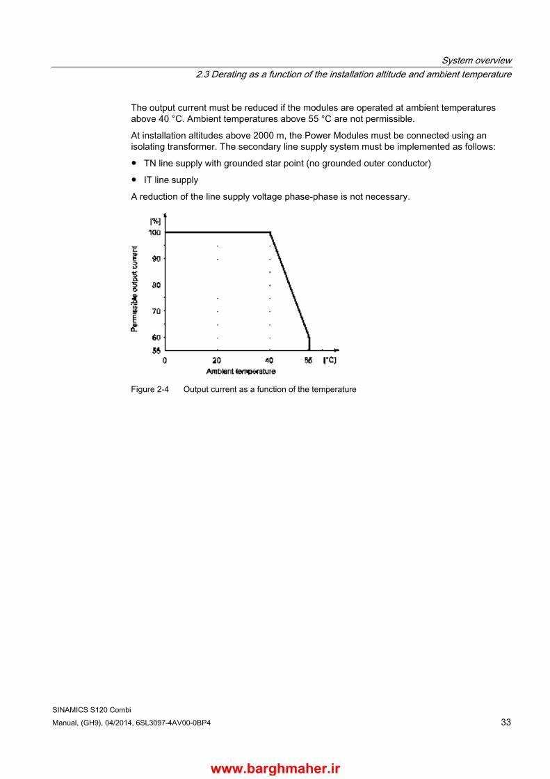
The output current must be reduced if the modules are operated at ambient temperatures above 40 °C. Ambient temperatures above 55 °C are not permissible.
At installation altitudes above 2000 m, the Power Modules must be connected using an isolating transformer. The secondary line supply system must be implemented as follows:
● TN line supply with grounded star point (no grounded outer conductor)
● IT line supply
A reduction of the line supply voltage phase-phase is not necessary.
Figure 2-4 Output current as a function of the temperature
www.barghmaher.ir

System overview 2.3 Derating as a function of the installation altitude and ambient temperature
SINAMICS S120 Combi 34 Manual, (GH9), 04/2014, 6SL3097-4AV00-0BP4
www.barghmaher.ir
SINAMICS S120 Combi Manual, (GH9), 04/2014, 6SL3097-4AV00-0BP4 35
Line-side power components 3 3.1 Introduction
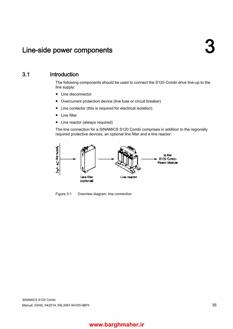
The following components should be used to connect the S120 Combi drive line-up to the line supply:
● Line disconnector
● Overcurrent protection device (line fuse or circuit breaker)
● Line contactor (this is required for electrical isolation)
● Line filter
● Line reactor (always required)
The line connection for a SINAMICS S120 Combi comprises in addition to the regionally required protective devices, an optional line filter and a line reactor:
Figure 3-1 Overview diagram, line connection
www.barghmaher.ir
Line-side power components 3.2 Information on the disconnector unit
SINAMICS S120 Combi 36 Manual, (GH9), 04/2014, 6SL3097-4AV00-0BP4
3.2 Information on the disconnector unit A line disconnector is required to correctly disconnect the drive line-up from the line supply. The line disconnector of the machine's electrical equipment can be used for this purpose. The line disconnector must be selected in compliance with the requirements of the internationally binding standard relating to the electrical equipment of machines EN 60204-1, Section 5.3. The relevant technical data and any other loads connected to the electrical equipment must be taken into account when making your selection.
NOTICE
Damage to loads connected in parallel caused by switching the line disconnector while under load
When switching the line disconnector under load, the voltage applied can damage external loads located parallel to the drive on the same switching component. • Firstly, interrupt the voltage at the X21 interface, terminal 3 (EP +24 V) and 4 (EP M) on
the S120 Combi. This can be achieved with a leading disconnecting auxiliary contact (≥ 10 ms), for example.
The accessories required for the line disconnector must be selected from the manufacturer catalogs. See also catalog NC61.
www.barghmaher.ir
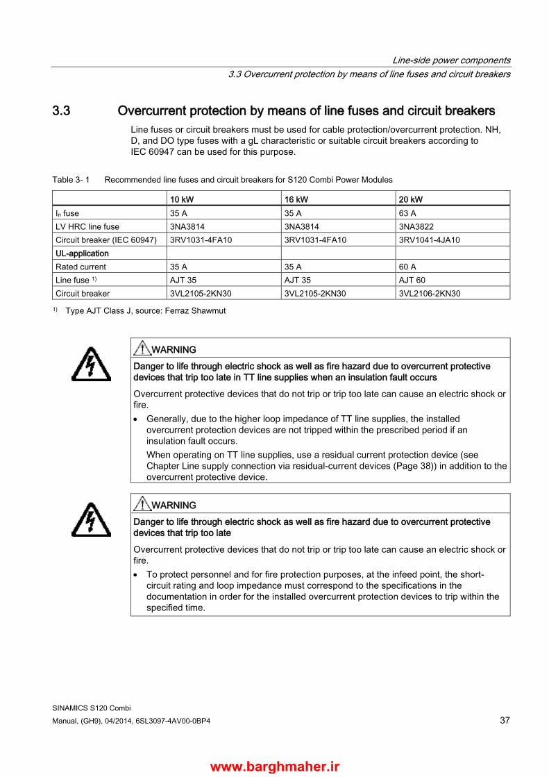
Line-side power components 3.3 Overcurrent protection by means of line fuses and circuit breakers
SINAMICS S120 Combi Manual, (GH9), 04/2014, 6SL3097-4AV00-0BP4 37
3.3 Overcurrent protection by means of line fuses and circuit breakers Line fuses or circuit breakers must be used for cable protection/overcurrent protection. NH, D, and DO type fuses with a gL characteristic or suitable circuit breakers according to IEC 60947 can be used for this purpose.
Table 3- 1 Recommended line fuses and circuit breakers for S120 Combi Power Modules
10 kW 16 kW 20 kW In fuse 35 A 35 A 63 A LV HRC line fuse 3NA3814 3NA3814 3NA3822 Circuit breaker (IEC 60947) 3RV1031-4FA10 3RV1031-4FA10 3RV1041-4JA10 UL-application Rated current 35 A 35 A 60 A Line fuse 1) AJT 35 AJT 35 AJT 60 Circuit breaker 3VL2105-2KN30 3VL2105-2KN30 3VL2106-2KN30 1) Type AJT Class J, source: Ferraz Shawmut
WARNING
Danger to life through electric shock as well as fire hazard due to overcurrent protective devices that trip too late in TT line supplies when an insulation fault occurs
Overcurrent protective devices that do not trip or trip too late can cause an electric shock or fire. • Generally, due to the higher loop impedance of TT line supplies, the installed
overcurrent protection devices are not tripped within the prescribed period if an insulation fault occurs. When operating on TT line supplies, use a residual current protection device (see Chapter Line supply connection via residual-current devices (Page 38)) in addition to the overcurrent protective device.
WARNING
Danger to life through electric shock as well as fire hazard due to overcurrent protective devices that trip too late
Overcurrent protective devices that do not trip or trip too late can cause an electric shock or fire. • To protect personnel and for fire protection purposes, at the infeed point, the short-
circuit rating and loop impedance must correspond to the specifications in the documentation in order for the installed overcurrent protection devices to trip within the specified time.
www.barghmaher.ir
Line-side power components 3.4 Line supply connection via residual-current devices
SINAMICS S120 Combi 38 Manual, (GH9), 04/2014, 6SL3097-4AV00-0BP4
WARNING
Danger to life due to electric shock caused by oversized fuses
Oversized fuses can result in significant levels of danger and also faults. • Use an adapted fuse corresponding to the table "Recommended line fuses and circuit
breakers for S120 Combi Power Modules".
3.4 Line supply connection via residual-current devices Selectively tripping, AC/DC-sensitive residual current protection devices (type B) can be used in addition to the overcurrent protection devices.
Residual-current operated circuit breakers (RCD)
WARNING
Danger to life due to electric shock when a residual current protection device does not trip
Overcurrent protective devices that do not trip or trip too late can cause an electric shock or fire. • Check or activate the residual current circuit breaker in regular cycles.
The following points must be observed when using a residual current circuit breaker:
● It is only permissible to use a type B delayed tripping, selective AC/DC-sensitive residual current circuit breaker.
● The loop impedance must comply with local installation regulations.
● The maximum total length of the shielded power cables in the drive line-up (motor cables incl. line supply cables from the line filter to the connecting terminals of the S120 Combi) may be no more than 175 m.
● Only recommended line filters must be used in operation.
● Switching elements (disconnector unit, contactors) for connecting and disconnecting the drive line-up have a maximum 35 ms delay time between closing/opening of the individual main contacts.
www.barghmaher.ir
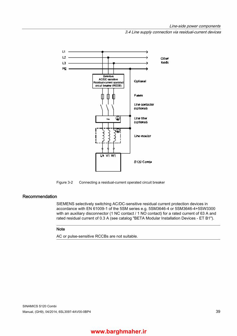
Line-side power components 3.4 Line supply connection via residual-current devices
SINAMICS S120 Combi Manual, (GH9), 04/2014, 6SL3097-4AV00-0BP4 39
Figure 3-2 Connecting a residual-current operated circuit breaker
Recommendation SIEMENS selectively switching AC/DC-sensitive residual current protection devices in accordance with EN 61009-1 of the 5SM series e.g. 5SM3646-4 or 5SM3646-4+5SW3300 with an auxiliary disconnector (1 NC contact / 1 NO contact) for a rated current of 63 A and rated residual current of 0.3 A (see catalog "BETA Modular Installation Devices - ET B1").
Note
AC or pulse-sensitive RCCBs are not suitable.
www.barghmaher.ir

Line-side power components 3.5 Overvoltage protection
SINAMICS S120 Combi 40 Manual, (GH9), 04/2014, 6SL3097-4AV00-0BP4
Derating characteristics
Figure 3-3 The rated current and tripping current depend on the ambient temperature for rated
residual currents over 100 mA
3.5 Overvoltage protection To protect the units against line-side surge voltages, you are advised to install an overvoltage protection device directly at the infeed point (upstream of the main switch). To comply with the requirements of CSA C22.2 No. 14-05, a type VZCA or VZCA2 surge arrester is absolutely mandatory. The Raycap company has suitable surge arresters.
www.barghmaher.ir
Line-side power components 3.6 Line filters
SINAMICS S120 Combi Manual, (GH9), 04/2014, 6SL3097-4AV00-0BP4 41
3.6 Line filters
3.6.1 Description Line filters have the task to attenuate conducted interference emission in the frequency range according to the specifications of EMC legislation. They are mainly effective in the frequency range from 150 kHz to 30 MHz; this is the range relevant to ensure compliance with the appropriate standard.
In conjunction with a line filter and the associated line reactor, drive line-ups with S120 Combi 10 kW, 16 kW and 20 kW Power Modules and a maximum total cable length up to 175 m, fulfill Category C2 according to EN 61800-3. An EMC compliant design is always assumed.
Note
The line filter is only suitable for direct connection to TN line supplies. An isolating transformer with vector group "Dyn" and grounded neutral point must be used when connecting to other line supplies. The line filter and the control cabinet must be connected to the isolating transformer neutral point through a low inductance connection.
3.6.2 Safety information
WARNING
Danger to life if the fundamental safety instructions and remaining risks are not carefully observed
If the fundamental safety instructions and remaining risks in Chapter 1 (Page 19) are not observed, accidents involving severe injuries or death may occur. • Adhere to the fundamental safety instructions. • When assessing the risk, take into account residual risks.
DANGER
Danger to life through electric shock due to residual charge
A hazardous voltage is still present for up to 5 minutes after the power supply has been switched off.
Contact with live parts can result in death or serious injury. • Measure the voltage before starting any work.
www.barghmaher.ir
Line-side power components 3.6 Line filters
SINAMICS S120 Combi 42 Manual, (GH9), 04/2014, 6SL3097-4AV00-0BP4
WARNING
Danger to life through interruption of the external protective conductor due to high leakage currents
The drive components conduct a high leakage current via the protective conductor. Touching conductive parts when the protective conductor is interrupted can result in death or serious injury. • Ensure that the external protective conductor satisfies at least one of the following
conditions: – It has been laid so that it is protected against mechanical damage.1) – If it is a single cable, it has a cross-section of at least 10 mm² Cu. – If it is a conductor of a multi-conductor cable, it has a cross-section of at least 2.5
mm² Cu. – It has a second protective conductor in parallel with the same cross-section. – It complies with the local regulations for equipment with increased leakage current. 1) Cables laid within control cabinets or closed machine housings are considered to be adequately protected against mechanical damage.
WARNING
Fire hazard due to overheating because of inadequate ventilation clearances
Inadequate ventilation clearances can cause overheating with a risk for personnel through smoke development and fire. This can also result in more downtimes and Line Modules may have a reduced service life. • It is absolutely essential that you maintain ventilation clearances according to the table
Ventilation clearances above and below the component (Page 312).
NOTICE
Damage to the line filter due to interchanging the input and output
The line filter can be damaged if the input and output connections are interchanged. • Connect the incoming line supply cable to LINE L1, L2, L3. • Connect the outgoing cable to line reactor at LOAD L1´, L2´, L3´.
NOTICE
Damage or fault to other loads when no line reactor is present
If the SINAMICS line filter is directly connected to the S120 Combi and not connected via the associated line reactor, other loads can be damaged or destroyed. • Connect the line filter to the S120 Combi via the associated line reactor. • Connect additional loads upstream of the SINAMICS line filter (if required, via a
separate line filter).
www.barghmaher.ir

Line-side power components 3.6 Line filters
SINAMICS S120 Combi Manual, (GH9), 04/2014, 6SL3097-4AV00-0BP4 43
NOTICE
Damage caused by third party filters
According to product standard IEC 61800-3, RFI suppression commensurate with the relevant rated conditions is required. Line filters and line reactors are required for this purpose.
The use of filters of other makes can lead to limit value violations, resonances, overvoltages and irreparable damage to motors or other equipment. • Only use line filters which are listed in this Manual. • The machine manufacturer must provide verification that the machine equipped with the
drive products and the installed suppression elements, e.g. line filters, is EMC-compliant before the machines are placed in the market.
NOTICE
Damage caused by line filters which are not approved for the SINAMICS S120 Combi
The integrated infeed can be damaged or destroyed when using line filters that have not been approved by SIEMENS for the SINAMICS S120 Combi Power Modules. Furthermore, line harmonics can occur that damage or destroy loads connected to the same line supply.
It is not permissible to connect other loads after the line filter. • Only use line filters which have been approved for the SINAMICS S120 Combi.
Note System fault level at the infeed point
In order to comply with EMC limit values, Category C2 according to EN 61800-3, the system fault level at the infeed point must be at least a factor 70 higher than the rated power of the integrated infeed.
Note
When a high-voltage test is conducted with alternating voltage in the system, the existing line filters must be disconnected in order to obtain accurate measurements.
www.barghmaher.ir
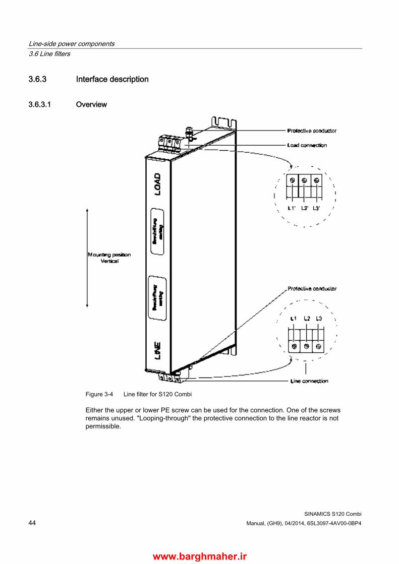
Line-side power components 3.6 Line filters
SINAMICS S120 Combi 44 Manual, (GH9), 04/2014, 6SL3097-4AV00-0BP4
3.6.3 Interface description
3.6.3.1 Overview
Figure 3-4 Line filter for S120 Combi
Either the upper or lower PE screw can be used for the connection. One of the screws remains unused. "Looping-through" the protective connection to the line reactor is not permissible.
www.barghmaher.ir
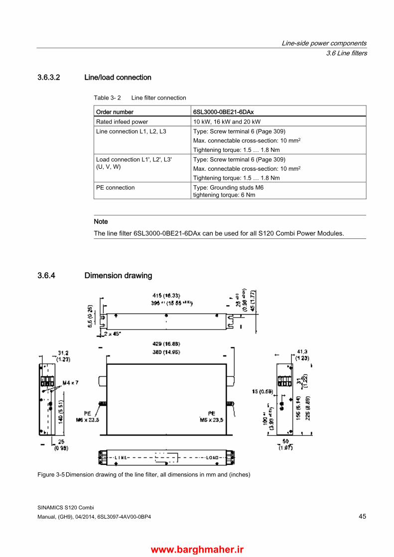
Line-side power components 3.6 Line filters
SINAMICS S120 Combi Manual, (GH9), 04/2014, 6SL3097-4AV00-0BP4 45
3.6.3.2 Line/load connection
Table 3- 2 Line filter connection
Order number 6SL3000-0BE21-6DAx Rated infeed power 10 kW, 16 kW and 20 kW Line connection L1, L2, L3 Type: Screw terminal 6 (Page 309)
Max. connectable cross-section: 10 mm2 Tightening torque: 1.5 … 1.8 Nm
Load connection L1', L2', L3' (U, V, W)
Type: Screw terminal 6 (Page 309) Max. connectable cross-section: 10 mm2 Tightening torque: 1.5 … 1.8 Nm
PE connection Type: Grounding studs M6 tightening torque: 6 Nm
Note
The line filter 6SL3000-0BE21-6DAx can be used for all S120 Combi Power Modules.
3.6.4 Dimension drawing
Figure 3-5 Dimension drawing of the line filter, all dimensions in mm and (inches)
www.barghmaher.ir

Line-side power components 3.6 Line filters
SINAMICS S120 Combi 46 Manual, (GH9), 04/2014, 6SL3097-4AV00-0BP4
3.6.5 Technical data
Table 3- 3 Technical data, line filter
6SL3000-0BE21-6DA0 Unit Rated power kW 10, 16 and 20 Connection voltage: Line voltage Line frequency
VAC Hz
3 AC 380 - 10 % (- 15 % < 1 min) … 3 AC 480 + 10 % 47 … 63 Hz
Rated current AAC 36 Power loss (see power loss tables (Page 318))
W 16 at 20 kW
Dimensions (W x H x D) mm 50 x 420 x 226 Weight, approx. kg 5 Degree of protection IP20
www.barghmaher.ir
Line-side power components 3.7 Line reactors
SINAMICS S120 Combi Manual, (GH9), 04/2014, 6SL3097-4AV00-0BP4 47
3.7 Line reactors
3.7.1 Description Line reactors for the S120 Combi limit low-frequency line harmonics to permissible values. For this reason, line reactors should always be used.
3.7.2 Safety information
WARNING
Danger to life if the fundamental safety instructions and remaining risks are not carefully observed
If the fundamental safety instructions and remaining risks in Chapter 1 (Page 19) are not observed, accidents involving severe injuries or death may occur. • Adhere to the fundamental safety instructions. • When assessing the risk, take into account residual risks.
DANGER
Danger to life due to electric shock in the event of missing touch protection
Death or serious injury can result when live parts are touched. • For the reactor, use touch protection according to IPXXA or corresponding to the local
installation regulations.
NOTICE
Damage caused by line reactors which are not approved for the SINAMICS S120 Combi
The following can occur if line reactors are used that have not been approved for SINAMICS S120 Combi by SIEMENS:
- The infeed in the S120 Combi may be damaged or destroyed.
- Line harmonics may occur that damage or destroy loads connected to the same line supply. • Only use line reactors which are listed in this Manual.
www.barghmaher.ir

Line-side power components 3.7 Line reactors
SINAMICS S120 Combi 48 Manual, (GH9), 04/2014, 6SL3097-4AV00-0BP4
NOTICE
Damage due to high temperatures of line reactors
The surface temperature of the line reactors may exceed 80°C. This can lead to temperature-related damage to adjacent components. • It is absolutely essential that you maintain clearances according to the table Ventilation
clearances above and below the component (Page 312) around the reactor. • If this clearance cannot be observed, additional measures such as shielding plates or a
cooling system must be provided.
NOTICE
Faults due to the magnetic fields of line reactors
Reactors generate magnetic fields. Components and cables can be damaged or affected by this. • Ensure there is sufficient clearance (at least 200 mm) from the reactors or shield them.
Note Connecting cables
The connecting cables between the line reactor and S120 Combi must be kept as short as possible.
If at all possible, shielded connecting cables should be used. When using unshielded connecting cables, the cores must be protected from rubbing against the shield connection clip.
www.barghmaher.ir
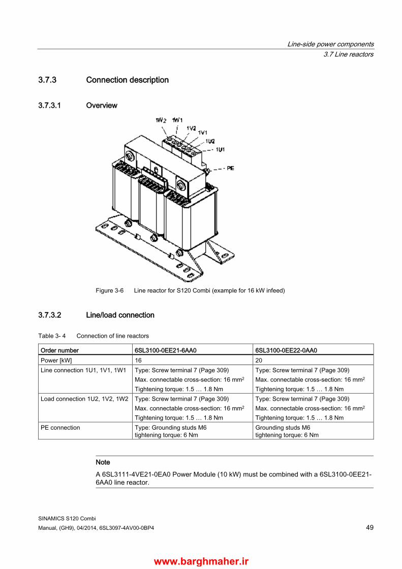
Line-side power components 3.7 Line reactors
SINAMICS S120 Combi Manual, (GH9), 04/2014, 6SL3097-4AV00-0BP4 49
3.7.3 Connection description
3.7.3.1 Overview
Figure 3-6 Line reactor for S120 Combi (example for 16 kW infeed)
3.7.3.2 Line/load connection
Table 3- 4 Connection of line reactors
Order number 6SL3100-0EE21-6AA0 6SL3100-0EE22-0AA0 Power [kW] 16 20 Line connection 1U1, 1V1, 1W1 Type: Screw terminal 7 (Page 309)
Max. connectable cross-section: 16 mm2 Tightening torque: 1.5 … 1.8 Nm
Type: Screw terminal 7 (Page 309) Max. connectable cross-section: 16 mm2 Tightening torque: 1.5 … 1.8 Nm
Load connection 1U2, 1V2, 1W2 Type: Screw terminal 7 (Page 309) Max. connectable cross-section: 16 mm2 Tightening torque: 1.5 … 1.8 Nm
Type: Screw terminal 7 (Page 309) Max. connectable cross-section: 16 mm2 Tightening torque: 1.5 … 1.8 Nm
PE connection Type: Grounding studs M6 tightening torque: 6 Nm
Grounding studs M6 tightening torque: 6 Nm
Note
A 6SL3111-4VE21-0EA0 Power Module (10 kW) must be combined with a 6SL3100-0EE21-6AA0 line reactor.
www.barghmaher.ir
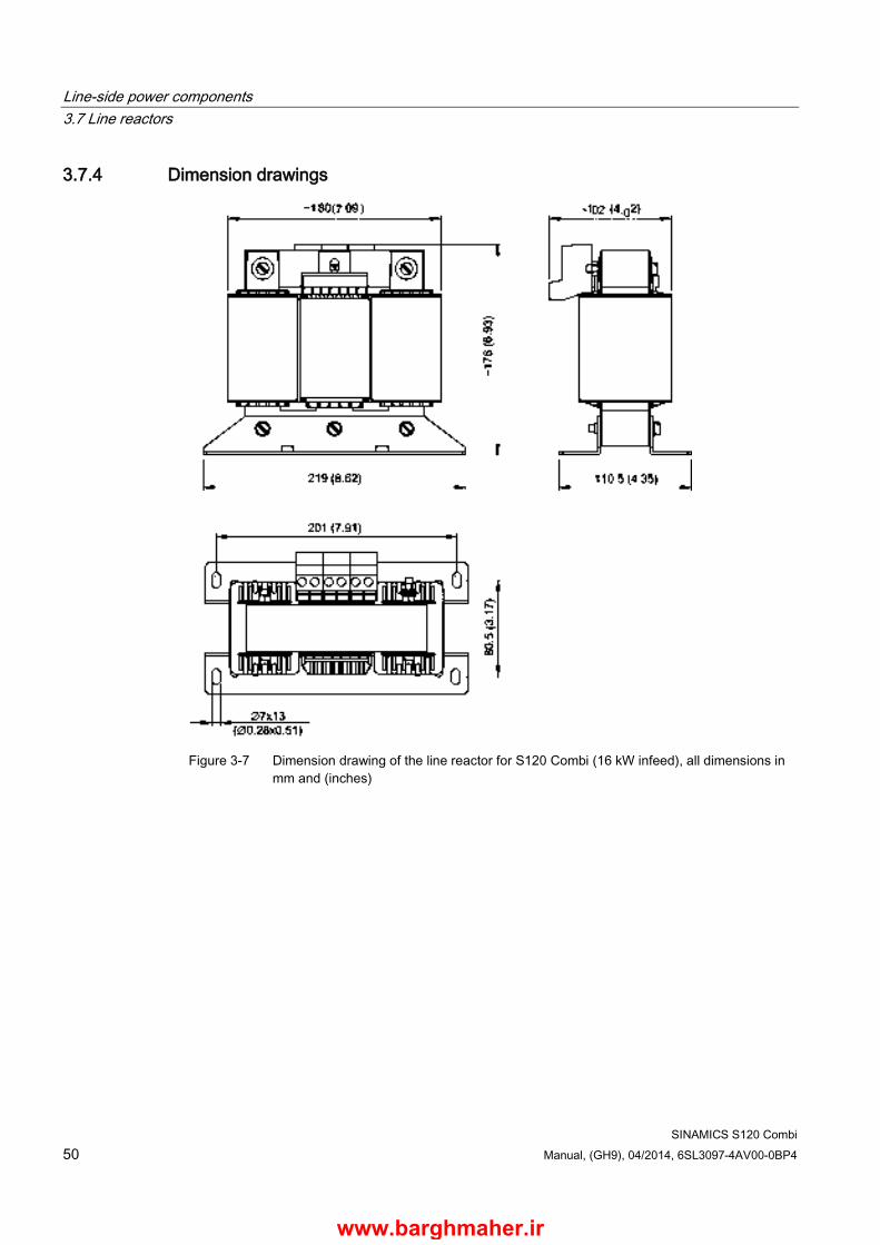
Line-side power components 3.7 Line reactors
SINAMICS S120 Combi 50 Manual, (GH9), 04/2014, 6SL3097-4AV00-0BP4
3.7.4 Dimension drawings
Figure 3-7 Dimension drawing of the line reactor for S120 Combi (16 kW infeed), all dimensions in
mm and (inches)
www.barghmaher.ir
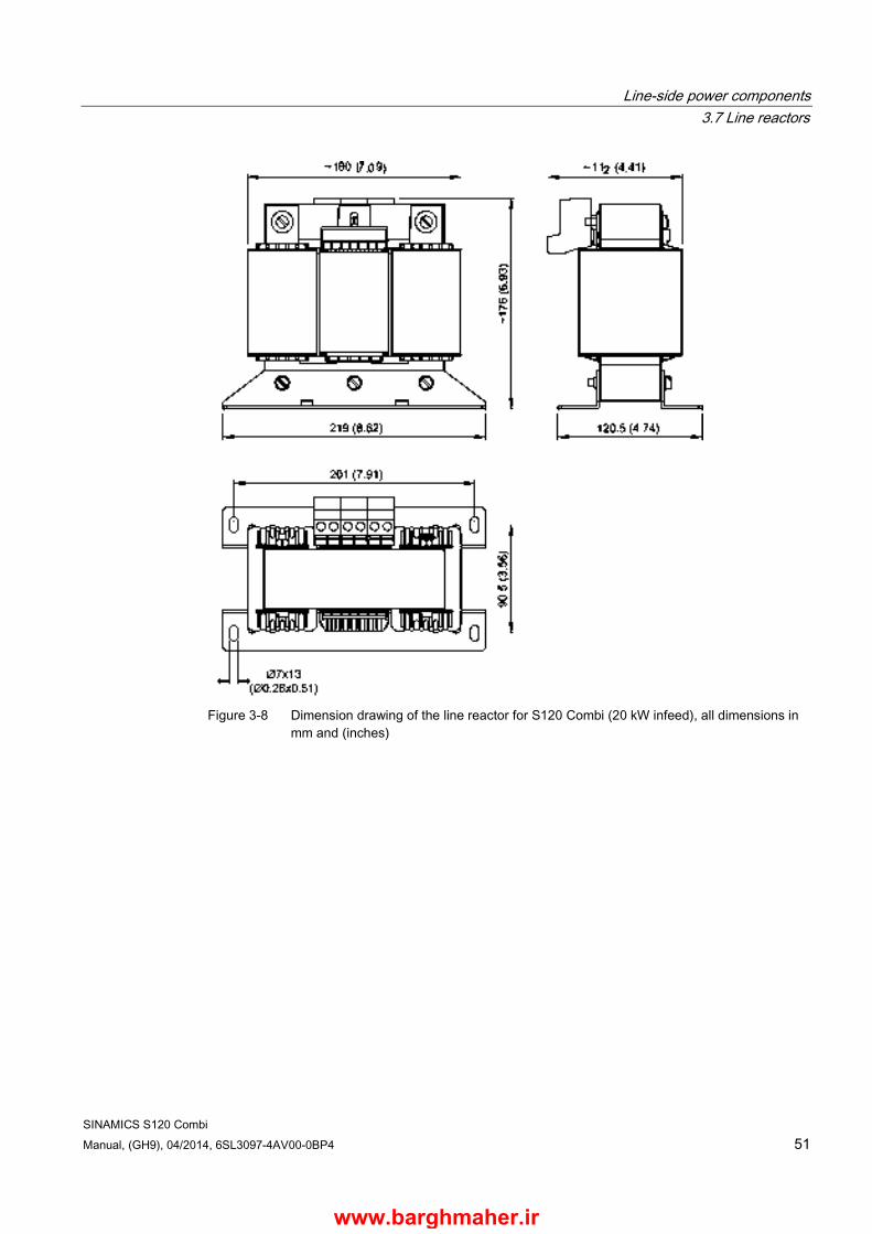
Line-side power components 3.7 Line reactors
SINAMICS S120 Combi Manual, (GH9), 04/2014, 6SL3097-4AV00-0BP4 51
Figure 3-8 Dimension drawing of the line reactor for S120 Combi (20 kW infeed), all dimensions in
mm and (inches)
www.barghmaher.ir

Line-side power components 3.7 Line reactors
SINAMICS S120 Combi 52 Manual, (GH9), 04/2014, 6SL3097-4AV00-0BP4
3.7.5 Technical data
Table 3- 5 Technical data, line reactors for S120 Combi
Unit 6SL3100-0EE21-6AA0
6SL3100-0EE22-0AA0
Rated power kW 16 20 Rated current Arms 28 33 Power loss (see power loss tables (Page 318))
W 75 98
Dimensions (W x H x D) mm 219 x 176 x 120 219 x 176 x 130 Weight kg 10.7 10.9 Degree of protection IPXXA IPXXA
www.barghmaher.ir

Line-side power components 3.8 Line connection versions
SINAMICS S120 Combi Manual, (GH9), 04/2014, 6SL3097-4AV00-0BP4 53
3.8 Line connection versions
3.8.1 Ways of connecting the line supply The following line connection versions are possible:
● Line connection components to be directly connected to the line supply
● Operating line connection components via an autotransformer
● Operating line connection components via an isolating transformer
Figure 3-9 Overview of line connection versions
www.barghmaher.ir
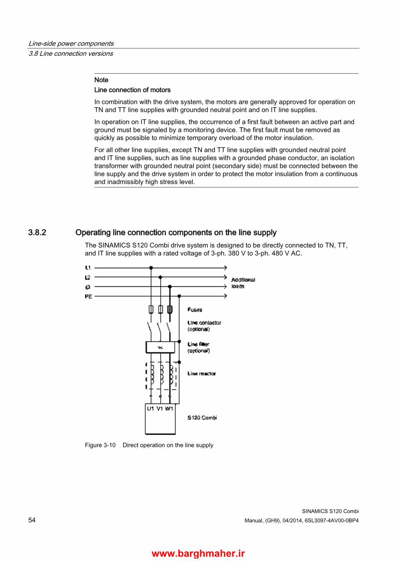
Line-side power components 3.8 Line connection versions
SINAMICS S120 Combi 54 Manual, (GH9), 04/2014, 6SL3097-4AV00-0BP4
Note Line connection of motors
In combination with the drive system, the motors are generally approved for operation on TN and TT line supplies with grounded neutral point and on IT line supplies.
In operation on IT line supplies, the occurrence of a first fault between an active part and ground must be signaled by a monitoring device. The first fault must be removed as quickly as possible to minimize temporary overload of the motor insulation.
For all other line supplies, except TN and TT line supplies with grounded neutral point and IT line supplies, such as line supplies with a grounded phase conductor, an isolation transformer with grounded neutral point (secondary side) must be connected between the line supply and the drive system in order to protect the motor insulation from a continuous and inadmissibly high stress level.
3.8.2 Operating line connection components on the line supply The SINAMICS S120 Combi drive system is designed to be directly connected to TN, TT, and IT line supplies with a rated voltage of 3-ph. 380 V to 3-ph. 480 V AC.
Figure 3-10 Direct operation on the line supply
www.barghmaher.ir
Line-side power components 3.8 Line connection versions
SINAMICS S120 Combi Manual, (GH9), 04/2014, 6SL3097-4AV00-0BP4 55
3.8.3 Operation of the line connection components via a transformer
3.8.3.1 Safety information
Note
If the system fault level is too low, this can result in faults at the integrated infeed of the SINAMICS S120 Combi Power Modules. It can also cause faults and damage to other equipment and devices that are connected to the same line connection point as the S120 Combi Power Module.
Note
Using a transformer with the S120 Combi Power Module does not replace the external line reactor.
3.8.3.2 Line connection conditions The S120 Combi is approved for operation on line supplies from SK line/Pn ≥ 70.
If a TN line supply is specified on the secondary side, a transformer with grounded neutral point must be used. On the other hand, to trigger the fuse within the specified time, the loop resistance must be low enough.
Vector group Any vector group with the neutral point brought out on the secondary side
www.barghmaher.ir
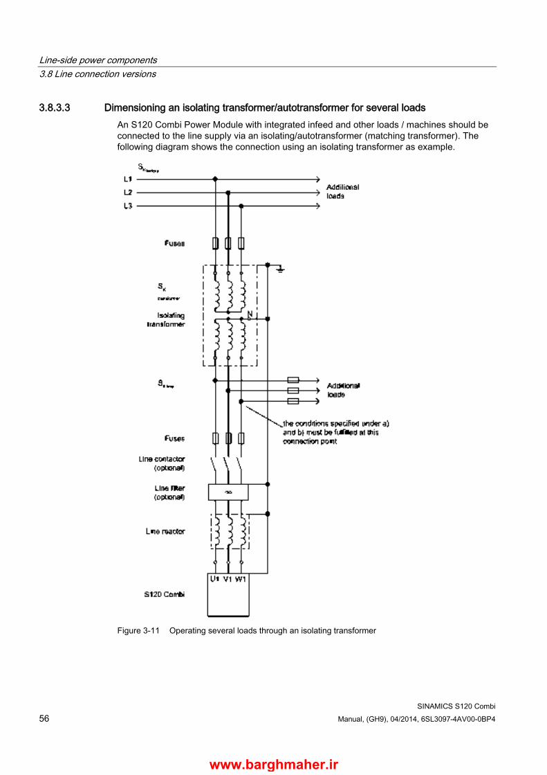
Line-side power components 3.8 Line connection versions
SINAMICS S120 Combi 56 Manual, (GH9), 04/2014, 6SL3097-4AV00-0BP4
3.8.3.3 Dimensioning an isolating transformer/autotransformer for several loads An S120 Combi Power Module with integrated infeed and other loads / machines should be connected to the line supply via an isolating/autotransformer (matching transformer). The following diagram shows the connection using an isolating transformer as example.
Figure 3-11 Operating several loads through an isolating transformer
www.barghmaher.ir
Line-side power components 3.8 Line connection versions
SINAMICS S120 Combi Manual, (GH9), 04/2014, 6SL3097-4AV00-0BP4 57
An isolating/autotransformer (matching transformer) must be dimensioned for the total of all loads connected to it. The apparent powers required must be determined and added as indicated in the table titled "Transformer configuration instructions". If the transformer is too small (Sn or Sk), this can lead to increased line voltage dips and faults in the line supply and in other loads at this connecting point.
If other loads are connected to the secondary side of the matching transformer, the boundary conditions indicated under a) and b) must be followed when selecting the matching transformer.
Sn1, Sn2 = calculated rated power of the transformer resulting from a) and b)
uk = short-circuit voltage of the matching transformer in % (must be between 1% ... 3% for the S120 Combi)
SK = short-circuit power.
WARNING
Danger to life through electric shock due to the connection of an unsuitable power supply
If the short-circuit power is not sufficiently high enough to trip the fuse in the event of a fault, there is a risk of electric shock or fire. • Use a power supply which generates a sufficient system fault level.
Supplementary conditions
a) Rated power
The rated power of the matching transformer Sn1 must always be a factor of 1.27 higher than the rated power Pn of the S120 Combi Power Module.
Sn1 ≥ 1.27 • Pn
Example:
The minimum rated power of a matching transformer for a 16 kW S120 Combi Power Module is 21 kVA.
b) Short-circuit power
In order to avoid faults and disturbances at the other loads that are connected to the secondary side of the matching transformer, the total short-circuit power of the plant connection and that of the matching transformer at the connection point must reach the following values:
SK line ≥ 70 • Pn
Special case:
When operating with only one supply at a transformer, the values may be reduced by the factor 0.73.
SK line ≥ 0.73 • 70 • Pn
For example SK line for 16 kW S120 Combi Power Module: SK line = 0.82 MVA = 820 kVA
www.barghmaher.ir
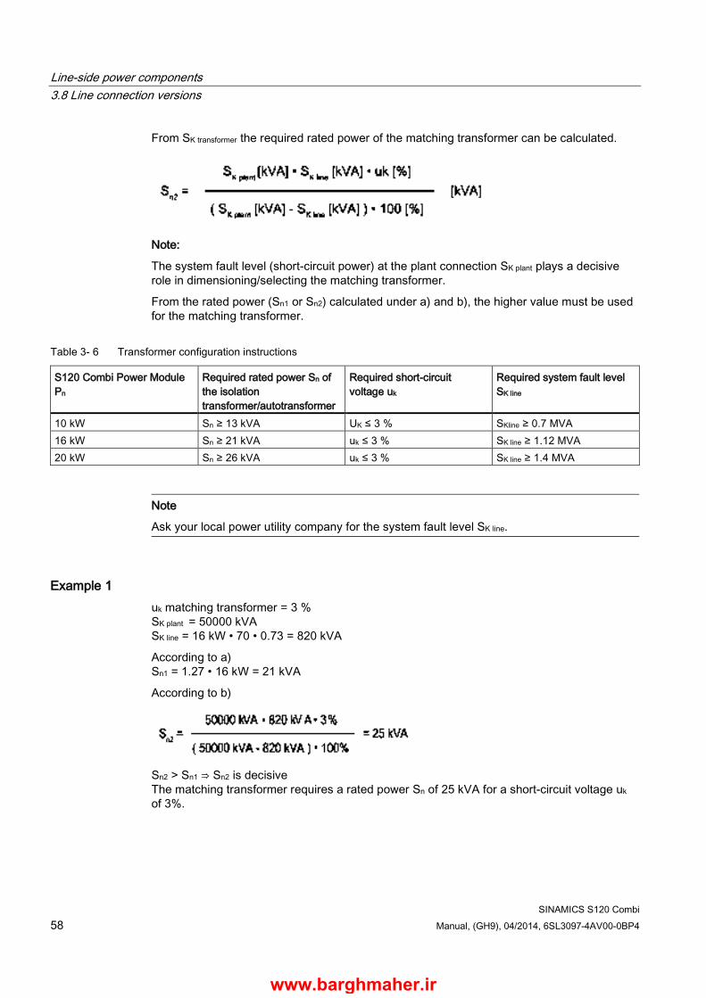
Line-side power components 3.8 Line connection versions
SINAMICS S120 Combi 58 Manual, (GH9), 04/2014, 6SL3097-4AV00-0BP4
From SK transformer the required rated power of the matching transformer can be calculated.
Note:
The system fault level (short-circuit power) at the plant connection SK plant plays a decisive role in dimensioning/selecting the matching transformer.
From the rated power (Sn1 or Sn2) calculated under a) and b), the higher value must be used for the matching transformer.
Table 3- 6 Transformer configuration instructions
S120 Combi Power Module Pn
Required rated power Sn of the isolation transformer/autotransformer
Required short-circuit voltage uk
Required system fault level SK line
10 kW Sn ≥ 13 kVA UK ≤ 3 % SKline ≥ 0.7 MVA 16 kW Sn ≥ 21 kVA uk ≤ 3 % SK line ≥ 1.12 MVA 20 kW Sn ≥ 26 kVA uk ≤ 3 % SK line ≥ 1.4 MVA
Note
Ask your local power utility company for the system fault level SK line.
Example 1 uk matching transformer = 3 % SK plant = 50000 kVA SK line = 16 kW • 70 • 0.73 = 820 kVA
According to a) Sn1 = 1.27 • 16 kW = 21 kVA
According to b)
Sn2 > Sn1 ⇒ Sn2 is decisive The matching transformer requires a rated power Sn of 25 kVA for a short-circuit voltage uk of 3%.
www.barghmaher.ir

Line-side power components 3.8 Line connection versions
SINAMICS S120 Combi Manual, (GH9), 04/2014, 6SL3097-4AV00-0BP4 59
Example 2 uk matching transformer = 1 % SK plant = 50000 kVA SK line = 16 kW • 70 • 0.73 = 820 kVA
according to a) Sn1 = 1.27 • 16 kW = 21 kVA
According to b)
Sn1 > Sn2 ⇒ Sn1 is decisive The matching transformer requires a rated power Sn of 21 kVA for a short-circuit voltage uk of 1%.
Example 3 If SK plant is lower, then a higher-rating transformer must be used. uk matching transformer = 3 % SK plant = 3000 kVA SK line = 16 kW • 70 • 0.73 = 820 kVA
according to a) Sn1 = 1.27 • 16 kW = 21 kVA
According to b)
Sn2 > Sn1 ⇒ Sn2 is decisive
The matching transformer requires a rated power Sn of 34 kVA for a short-circuit voltage uk of 3%.
Example 4 If SK plant is lower, you can use, alternatively to example 3, a transformer with a lower uk. uk matching transformer = 1 %, SK plant = 3,000 kVA SK line = 16 kW • 70 • 0.73 = 820 kVA
according to a) Sn1 = 1.27 • 16 kW = 21 kVA
According to b)
www.barghmaher.ir
Line-side power components 3.8 Line connection versions
SINAMICS S120 Combi 60 Manual, (GH9), 04/2014, 6SL3097-4AV00-0BP4
Sn1 > Sn2 ⇒ Sn1 is decisive
The matching transformer requires a rated power Sn of 21 kVA for a short-circuit voltage uk of 1%.
Note
Sn2 for the matching transformer can be reduced by reducing uk. In the examples listed above, the power drawn from other loads has not been taken into account.
3.8.3.4 Operating line connection components via an autotransformer An autotransformer can be used to adapt the voltage in the range up to 3-ph. 480 V AC 10 %.
WARNING
Danger to life through electric shock due to high voltage
If the voltage applied is too high for the existing insulation, there is a danger of electric shock. • Use an isolating transformer for voltages from 3-ph. 480 V + 10 %.
NOTICE
Damage when using an autotransformer
If an autotransformer is used, safe electrical separation is no longer possible for a line voltage higher than 480 V +10 %. This can lead to damage or a fault in the device. • In this case, use an isolation transformer.
www.barghmaher.ir
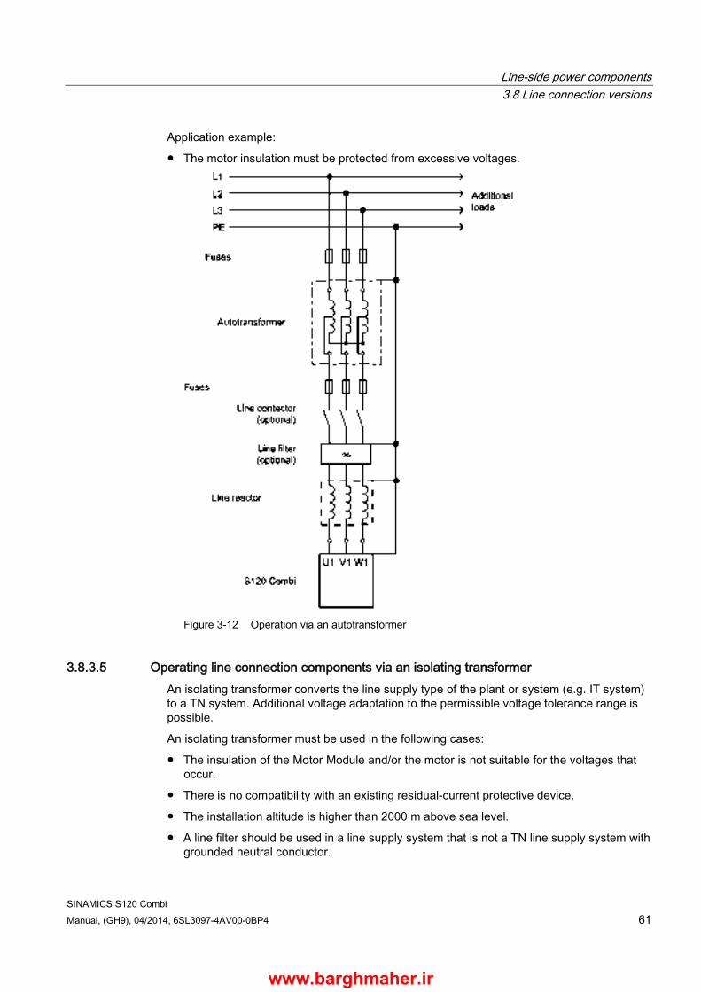
Line-side power components 3.8 Line connection versions
SINAMICS S120 Combi Manual, (GH9), 04/2014, 6SL3097-4AV00-0BP4 61
Application example:
● The motor insulation must be protected from excessive voltages.
Figure 3-12 Operation via an autotransformer
3.8.3.5 Operating line connection components via an isolating transformer An isolating transformer converts the line supply type of the plant or system (e.g. IT system) to a TN system. Additional voltage adaptation to the permissible voltage tolerance range is possible.
An isolating transformer must be used in the following cases:
● The insulation of the Motor Module and/or the motor is not suitable for the voltages that occur.
● There is no compatibility with an existing residual-current protective device.
● The installation altitude is higher than 2000 m above sea level.
● A line filter should be used in a line supply system that is not a TN line supply system with grounded neutral conductor.
www.barghmaher.ir
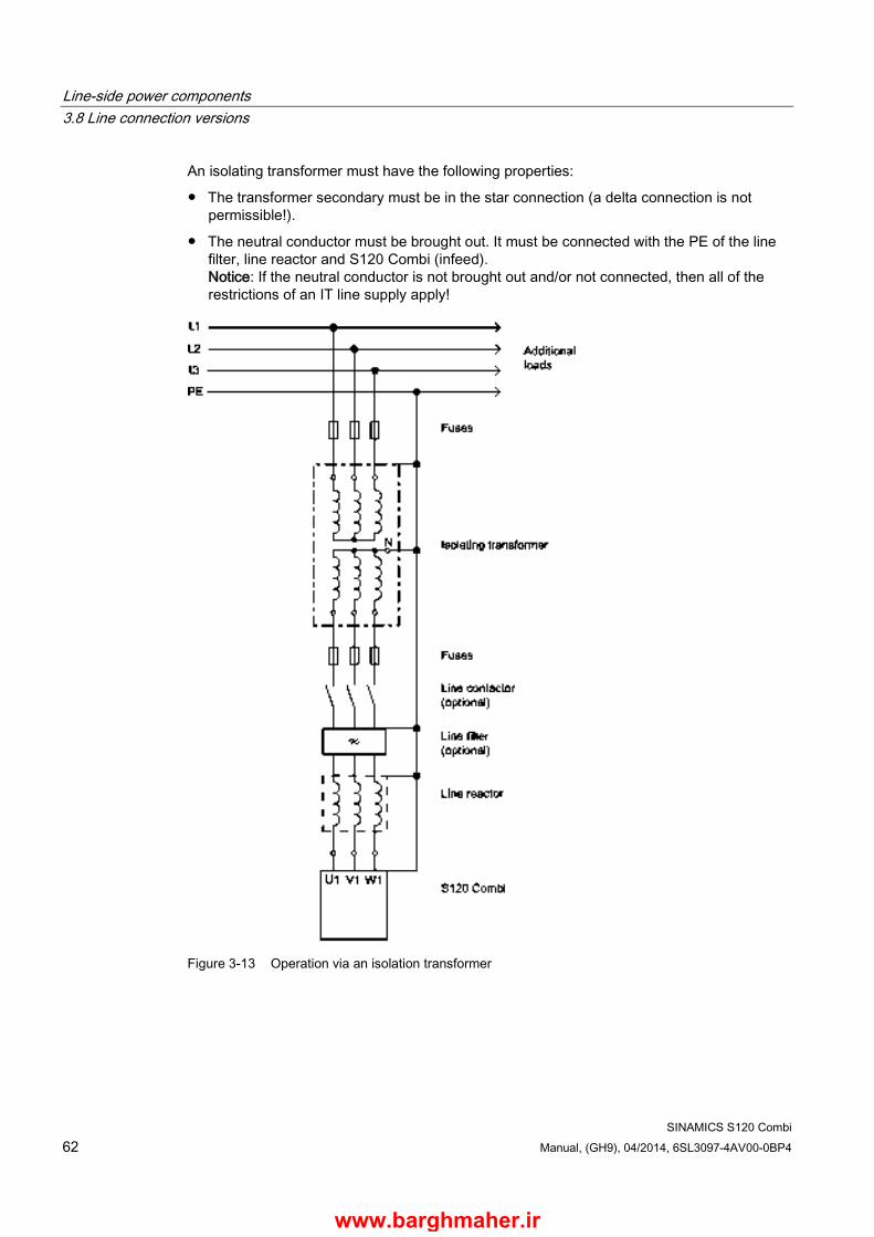
Line-side power components 3.8 Line connection versions
SINAMICS S120 Combi 62 Manual, (GH9), 04/2014, 6SL3097-4AV00-0BP4
An isolating transformer must have the following properties:
● The transformer secondary must be in the star connection (a delta connection is not permissible!).
● The neutral conductor must be brought out. It must be connected with the PE of the line filter, line reactor and S120 Combi (infeed). Notice: If the neutral conductor is not brought out and/or not connected, then all of the restrictions of an IT line supply apply!
Figure 3-13 Operation via an isolation transformer
www.barghmaher.ir

SINAMICS S120 Combi Manual, (GH9), 04/2014, 6SL3097-4AV00-0BP4 63
S120 Combi Power Modules 4 4.1 Introduction
4.1.1 Description
The SINAMICS S120 Combi The S120 Combi is a Power Module with integrated infeed, Motor Modules (inverter) for 3 or 4 axes and a TTL encoder evaluation for the spindle. The S120 Combi is available in the following versions for various current ratings:
● 3 axes Power Module with infeed, spindle and 2 feed axes
● 4 axes Power Module with infeed, spindle and 3 feed axes
The Power Modules are cooled using external air cooling that employs through-hole technology. The required fan unit is optionally available. A fan solution on the customer side with comparable rated data is possible.
The S120 Combi is capable of infeed/regenerative feedback (energy recovery). The infeed provides the integrated Motor Modules with an uncontrolled DC voltage.
In the infeed mode regarding the current and voltage waveforms, the infeed has a typical characteristic of a 6-pulse diode rectifier bridge. In the energy recovery mode, the current waveform is a square wave. The energy recovery is switched in depending on the power that is fed back. Energy recovery is deactivated when the infeed is operating under no-load conditions.
The S120 Combi is suitable for direct operation on TN, IT and TT line supplies.
Controlling the motor holding brake The S120 Combi has an integrated brake control function for a motor holding brake. The motor holding brake is connected at terminal X11. The assignment of the motor holding brake to the feed axes of the S120 Combi can be freely parameterized using the software. Motor holding brakes up to 1 A are controlled.
Temperature sensor connection A temperature sensor can either be connected using terminal X21 or using the sub-D connector of the TTL encoder (X220). The interface used is selected using the software.
www.barghmaher.ir

S120 Combi Power Modules 4.1 Introduction
SINAMICS S120 Combi 64 Manual, (GH9), 04/2014, 6SL3097-4AV00-0BP4
Encoder connection The S120 Combi supports sin/cos encoders, TTL encoders and encoders with integrated DRIVE-CLiQ with a 5 V supply for motors. The TTL encoder is connected via the integrated X220 encoder interface and is permanently assigned to spindle output X2. The sin/cos encoder for spindle output X2 is connected to interface X205 via an SMxxx Sensor Module. In this particular case, encoder interface X220 is automatically inactive.
Fixed topology rules apply when connecting DRIVE-CLiQ encoders. Each feed axis is assigned exactly to one DRIVE-CLiQ interface (see Section Topology rules for DRIVE-CLiQ (Page 127)).
HTL encoders, SSI encoders and a 24 V encoder power supply are not supported by the integrated encoder interface on the S120 Combi.
Interface assignment The assignment of the DRIVE-CLiQ interfaces on the S120 Combi is permanently defined and must not be changed.
The DRIVE-CLiQ connection of the expansion axes is always implemented via DRIVE-CLiQ interface X101 at the SINUMERIK control. You can find a detailed description in Chapters Interface description (Page 71) of the S120 Combi and Topology rules for DRIVE-CLiQ (Page 127).
Measuring systems and additional encoders should always be connected via the DMC20 Hub Module.
Internal temperature sensing and internal fan The internal temperature of the S120 Combi is sensed. In conjunction with this is the temperature-dependent control of the internal fan to cool the inside of the unit. The S120 Combi Power Module is switched off if its internal temperature becomes too high.
An operating hours counter for the internal fan is available via the software in parameter P0254 (infeed) (see SINAMICS S120/S150 List Manual).
www.barghmaher.ir
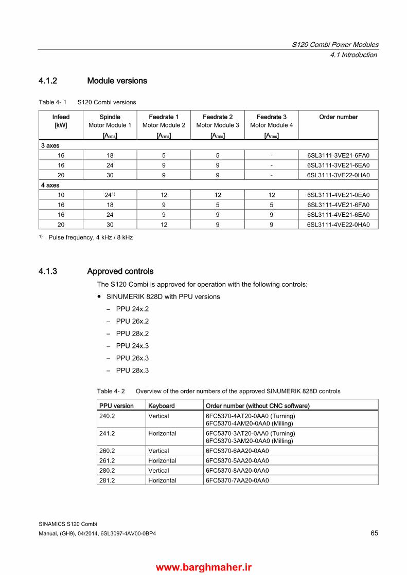
S120 Combi Power Modules 4.1 Introduction
SINAMICS S120 Combi Manual, (GH9), 04/2014, 6SL3097-4AV00-0BP4 65
4.1.2 Module versions
Table 4- 1 S120 Combi versions
Infeed [kW]
Spindle Motor Module 1
[Arms]
Feedrate 1 Motor Module 2
[Arms]
Feedrate 2 Motor Module 3
[Arms]
Feedrate 3 Motor Module 4
[Arms]
Order number
3 axes 16 18 5 5 - 6SL3111-3VE21-6FA0 16 24 9 9 - 6SL3111-3VE21-6EA0 20 30 9 9 - 6SL3111-3VE22-0HA0
4 axes 10 241) 12 12 12 6SL3111-4VE21-0EA0 16 18 9 5 5 6SL3111-4VE21-6FA0 16 24 9 9 9 6SL3111-4VE21-6EA0 20 30 12 9 9 6SL3111-4VE22-0HA0
1) Pulse frequency, 4 kHz / 8 kHz
4.1.3 Approved controls The S120 Combi is approved for operation with the following controls:
● SINUMERIK 828D with PPU versions
– PPU 24x.2
– PPU 26x.2
– PPU 28x.2
– PPU 24x.3
– PPU 26x.3
– PPU 28x.3
Table 4- 2 Overview of the order numbers of the approved SINUMERIK 828D controls
PPU version Keyboard Order number (without CNC software) 240.2 Vertical 6FC5370-4AT20-0AA0 (Turning)
6FC5370-4AM20-0AA0 (Milling) 241.2 Horizontal 6FC5370-3AT20-0AA0 (Turning)
6FC5370-3AM20-0AA0 (Milling) 260.2 Vertical 6FC5370-6AA20-0AA0 261.2 Horizontal 6FC5370-5AA20-0AA0 280.2 Vertical 6FC5370-8AA20-0AA0 281.2 Horizontal 6FC5370-7AA20-0AA0
www.barghmaher.ir
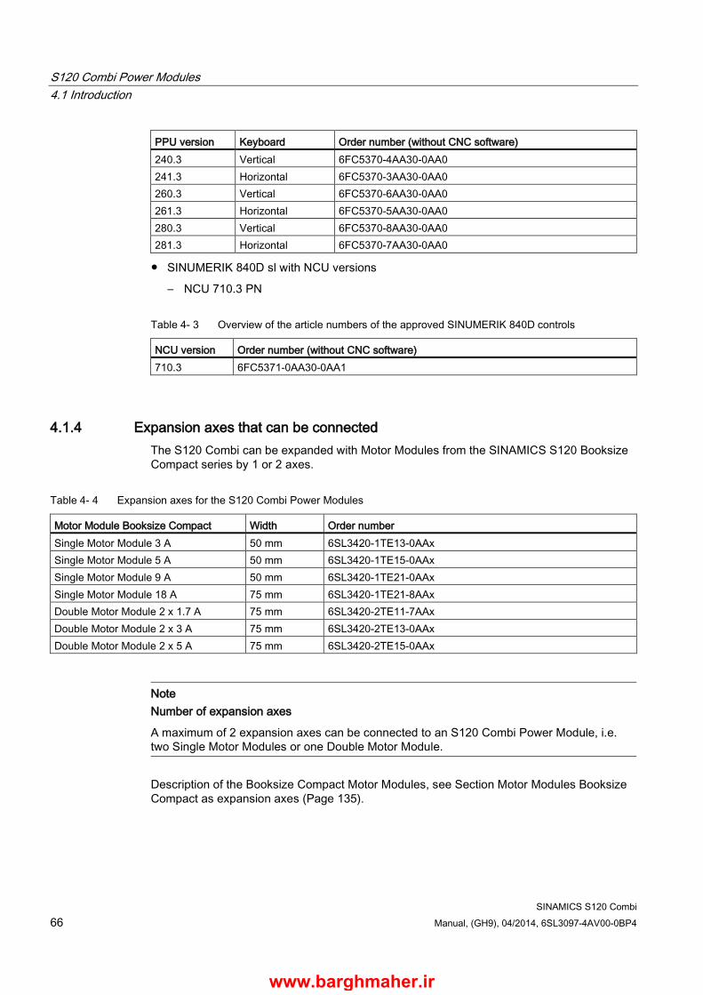
S120 Combi Power Modules 4.1 Introduction
SINAMICS S120 Combi 66 Manual, (GH9), 04/2014, 6SL3097-4AV00-0BP4
PPU version Keyboard Order number (without CNC software) 240.3 Vertical 6FC5370-4AA30-0AA0 241.3 Horizontal 6FC5370-3AA30-0AA0 260.3 Vertical 6FC5370-6AA30-0AA0 261.3 Horizontal 6FC5370-5AA30-0AA0 280.3 Vertical 6FC5370-8AA30-0AA0 281.3 Horizontal 6FC5370-7AA30-0AA0
● SINUMERIK 840D sl with NCU versions
– NCU 710.3 PN
Table 4- 3 Overview of the article numbers of the approved SINUMERIK 840D controls
NCU version Order number (without CNC software) 710.3 6FC5371-0AA30-0AA1
4.1.4 Expansion axes that can be connected The S120 Combi can be expanded with Motor Modules from the SINAMICS S120 Booksize Compact series by 1 or 2 axes.
Table 4- 4 Expansion axes for the S120 Combi Power Modules
Motor Module Booksize Compact Width Order number Single Motor Module 3 A 50 mm 6SL3420-1TE13-0AAx Single Motor Module 5 A 50 mm 6SL3420-1TE15-0AAx Single Motor Module 9 A 50 mm 6SL3420-1TE21-0AAx Single Motor Module 18 A 75 mm 6SL3420-1TE21-8AAx Double Motor Module 2 x 1.7 A 75 mm 6SL3420-2TE11-7AAx Double Motor Module 2 x 3 A 75 mm 6SL3420-2TE13-0AAx Double Motor Module 2 x 5 A 75 mm 6SL3420-2TE15-0AAx
Note Number of expansion axes
A maximum of 2 expansion axes can be connected to an S120 Combi Power Module, i.e. two Single Motor Modules or one Double Motor Module.
Description of the Booksize Compact Motor Modules, see Section Motor Modules Booksize Compact as expansion axes (Page 135).
www.barghmaher.ir
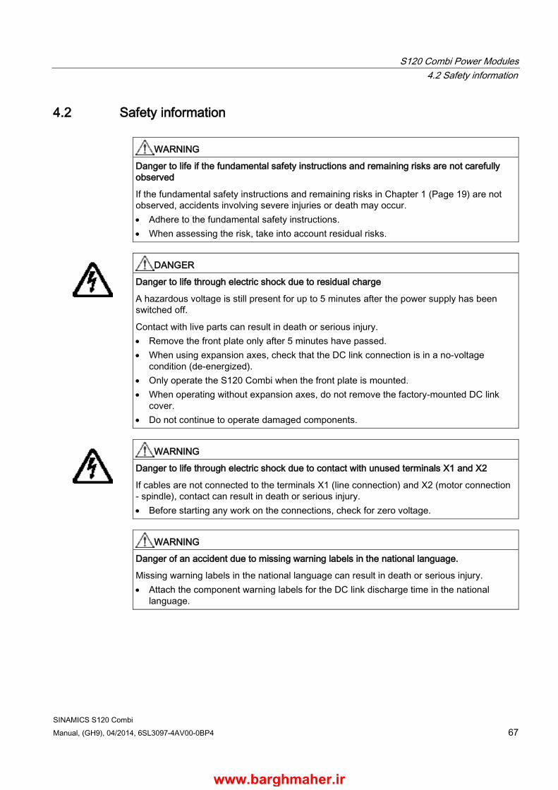
S120 Combi Power Modules 4.2 Safety information
SINAMICS S120 Combi Manual, (GH9), 04/2014, 6SL3097-4AV00-0BP4 67
4.2 Safety information
WARNING
Danger to life if the fundamental safety instructions and remaining risks are not carefully observed
If the fundamental safety instructions and remaining risks in Chapter 1 (Page 19) are not observed, accidents involving severe injuries or death may occur. • Adhere to the fundamental safety instructions. • When assessing the risk, take into account residual risks.
DANGER
Danger to life through electric shock due to residual charge
A hazardous voltage is still present for up to 5 minutes after the power supply has been switched off.
Contact with live parts can result in death or serious injury. • Remove the front plate only after 5 minutes have passed. • When using expansion axes, check that the DC link connection is in a no-voltage
condition (de-energized). • Only operate the S120 Combi when the front plate is mounted. • When operating without expansion axes, do not remove the factory-mounted DC link
cover. • Do not continue to operate damaged components.
WARNING
Danger to life through electric shock due to contact with unused terminals X1 and X2
If cables are not connected to the terminals X1 (line connection) and X2 (motor connection - spindle), contact can result in death or serious injury. • Before starting any work on the connections, check for zero voltage.
WARNING
Danger of an accident due to missing warning labels in the national language.
Missing warning labels in the national language can result in death or serious injury. • Attach the component warning labels for the DC link discharge time in the national
language.
www.barghmaher.ir
S120 Combi Power Modules 4.2 Safety information
SINAMICS S120 Combi 68 Manual, (GH9), 04/2014, 6SL3097-4AV00-0BP4
WARNING
Danger to life through electric shock due to existing network connection
If the S120 Combi is not disconnected from the line supply system (e.g. via the line contactor or main switch), the DC link remains charged.
Contact with live parts can result in death or serious injury. • Disconnect the S120 Combi from the line supply, via the line contactor or main switch.
WARNING
Danger to life through electric shock as well as fire hazard due to overcurrent protective devices that trip too late
Overcurrent protective devices that do not trip or trip too late can cause an electric shock or fire. • To protect personnel and for fire protection purposes, at the infeed point, the short-
circuit rating and loop impedance must correspond to the specifications in the documentation in order for the installed overcurrent protection devices to trip within the specified time.
WARNING
Danger to life through interruption of the external protective conductor due to high leakage currents
The drive components conduct a high leakage current via the protective conductor. Touching conductive parts when the protective conductor is interrupted can result in death or serious injury. • Ensure that the external protective conductor satisfies at least one of the following
conditions: – It has been laid so that it is protected against mechanical damage.1) – If it is a single cable, it has a cross-section of at least 10 mm² Cu. – If it is a conductor of a multi-conductor cable, it has a cross-section of at least 2.5
mm² Cu. – It has a second protective conductor in parallel with the same cross-section. – It complies with the local regulations for equipment with increased leakage current. 1) Cables laid within control cabinets or closed machine housings are considered to be adequately protected against mechanical damage.
WARNING
Danger to life through electric shock due to incorrectly laid brake cables
If brake cables are laid without safe electrical separation, the insulation can fail with an electric shock. • Close the holding brake with the specified MOTION-CONNECT cable. • Only use third-party cables with safe electrically separated brake cores or lay the brake
cores with safe electrical separation.
www.barghmaher.ir

S120 Combi Power Modules 4.2 Safety information
SINAMICS S120 Combi Manual, (GH9), 04/2014, 6SL3097-4AV00-0BP4 69
WARNING
Danger to life through electric shock due to unconnected cable shields
Hazardous touch voltages can occur through capacitive cross-coupling due to unconnected cable shields. • As a minimum, connect cable shields and the cores of power cables that are not used
(e.g. brake cores) at one end at the grounded housing potential.
WARNING
Fire hazard due to overheating because of inadequate ventilation clearances
Inadequate ventilation clearances can cause overheating with a risk for personnel through smoke development and fire. This can also result in more downtimes and Line Modules may have a reduced service life. • It is absolutely essential that you maintain ventilation clearances according to the table
Ventilation clearances above and below the component (Page 312).
WARNING
Danger to life due to electric shock in the event of voltage flashovers at the temperature sensor
Voltage flashovers in the signal electronics can occur in motors without safe electrical separation of the temperature sensors. • Only use temperature sensors that fully comply with the specifications of the safety
isolation. • If safe electrical separation cannot be guaranteed (for linear motors or third-party
motors, for example), use a Sensor Module External (SME120 or SME125) or Terminal Module TM120.
WARNING
Fire hazard due to overheating when permissible cable lengths are exceeded
Excessively long cable lengths can cause components to overheat with the associated risk of fire and development of smoke. • The total length of the power cables (motor feeder cables etc.) must not exceed 175 m.
WARNING
Fire hazard and damage to devices during operation without a line reactor
Operating a system without a line reactor can trigger a fire with smoke development. • Do not operate the system without a line reactor.
www.barghmaher.ir

S120 Combi Power Modules 4.2 Safety information
SINAMICS S120 Combi 70 Manual, (GH9), 04/2014, 6SL3097-4AV00-0BP4
NOTICE
Material damage due to loose power connections
Insufficient tightening torques or vibrations can result in faulty electrical connections. This can cause fire damage or malfunctions. • Tighten all the DC link busbar screws with the specified tightening torques (1.8 Nm
tolerance +30 %). • Check the tightening torques of all power connections at regular intervals and tighten
them when required. This applies in particular after transport.
NOTICE
Damage through use of incorrect DRIVE-CLiQ cables
Damage or malfunctions can occur on the devices or system when incorrect or unreleased DRIVE-CLiQ cables are used. • Only use suitable DRIVE-CLiQ cables that have been released by Siemens for the
respective application.
Note Operation on line supplies where energy recovery is not possible
In line supply systems without energy recovery capability (e.g. a diesel generator), device faults can occur due to a lack of dissipation of braking energy. • Deactivate the energy recovery capability of the Smart Line Modules using the
corresponding parameter (see the SINAMICS S120/S150 List Manual). • The braking energy must then be dissipated via an additional Braking Module with
braking resistor in the drive line-up.
Note Shutting down the device in the event of contaminated external heat sinks
For components with external air cooling, the fan and the heat sinks can accumulate a lot of pollution. If the cooling air requirement is not provided by the filter fan, the components cannot output their specified power. This can cause the temperature monitoring function in the components to respond. • Check the fans and heat sinks for pollution at regular intervals and clean them when
necessary.
www.barghmaher.ir
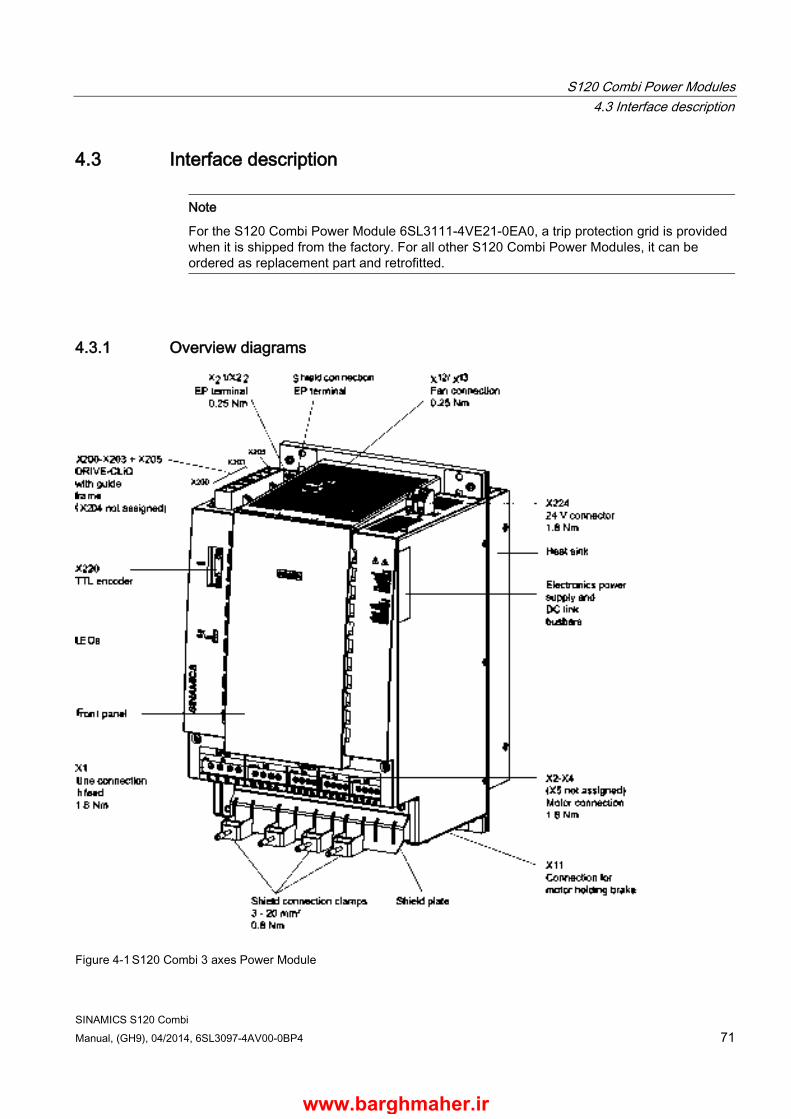
S120 Combi Power Modules 4.3 Interface description
SINAMICS S120 Combi Manual, (GH9), 04/2014, 6SL3097-4AV00-0BP4 71
4.3 Interface description
Note
For the S120 Combi Power Module 6SL3111-4VE21-0EA0, a trip protection grid is provided when it is shipped from the factory. For all other S120 Combi Power Modules, it can be ordered as replacement part and retrofitted.
4.3.1 Overview diagrams
Figure 4-1 S120 Combi 3 axes Power Module
www.barghmaher.ir

S120 Combi Power Modules 4.3 Interface description
SINAMICS S120 Combi 72 Manual, (GH9), 04/2014, 6SL3097-4AV00-0BP4
Figure 4-2 S120 Combi 3 axes Power Module: View from the top
Figure 4-3 S120 Combi 3 axes Power Module: View from below
www.barghmaher.ir
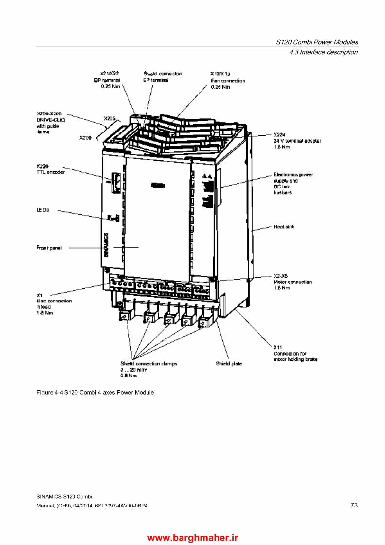
S120 Combi Power Modules 4.3 Interface description
SINAMICS S120 Combi Manual, (GH9), 04/2014, 6SL3097-4AV00-0BP4 73
Figure 4-4 S120 Combi 4 axes Power Module
www.barghmaher.ir

S120 Combi Power Modules 4.3 Interface description
SINAMICS S120 Combi 74 Manual, (GH9), 04/2014, 6SL3097-4AV00-0BP4
Figure 4-5 S120 Combi 4 axes Power Module: View from the top
Figure 4-6 S120 Combi 4 axes Power Module: View from below
www.barghmaher.ir
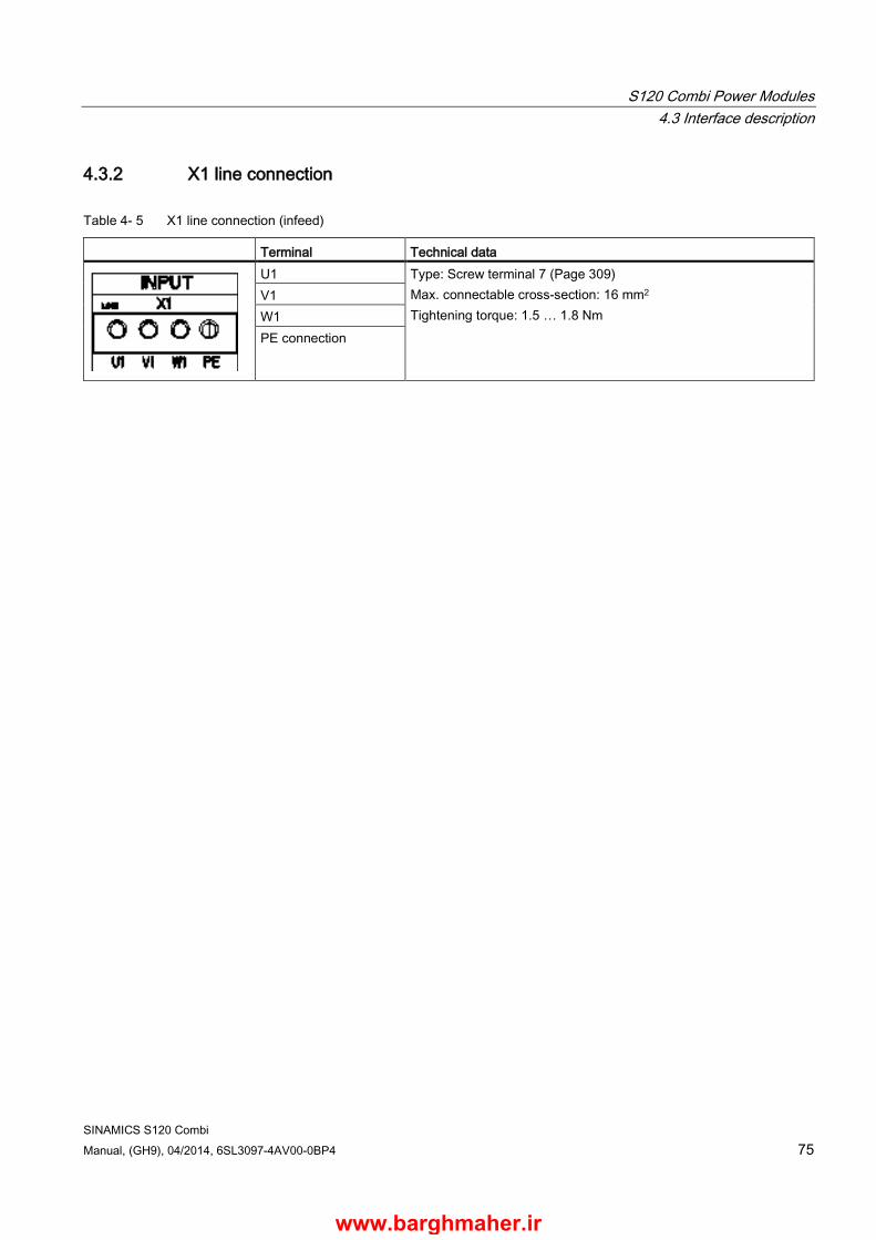
S120 Combi Power Modules 4.3 Interface description
SINAMICS S120 Combi Manual, (GH9), 04/2014, 6SL3097-4AV00-0BP4 75
4.3.2 X1 line connection
Table 4- 5 X1 line connection (infeed)
Terminal Technical data
U1 Type: Screw terminal 7 (Page 309) Max. connectable cross-section: 16 mm2 Tightening torque: 1.5 … 1.8 Nm
V1 W1 PE connection
www.barghmaher.ir
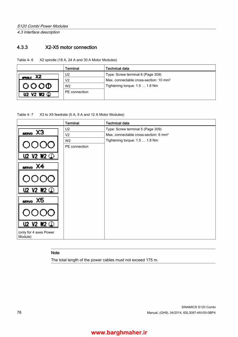
S120 Combi Power Modules 4.3 Interface description
SINAMICS S120 Combi 76 Manual, (GH9), 04/2014, 6SL3097-4AV00-0BP4
4.3.3 X2-X5 motor connection
Table 4- 6 X2 spindle (18 A, 24 A and 30 A Motor Modules)
Terminal Technical data
U2 Type: Screw terminal 6 (Page 309) Max. connectable cross-section: 10 mm2 Tightening torque: 1.5 … 1.8 Nm
V2 W2 PE connection
Table 4- 7 X3 to X5 feedrate (5 A, 9 A and 12 A Motor Modules)
Terminal Technical data
(only for 4 axes Power Module)
U2 Type: Screw terminal 5 (Page 309) Max. connectable cross-section: 6 mm2 Tightening torque: 1.5 … 1.8 Nm
V2 W2 PE connection
Note
The total length of the power cables must not exceed 175 m.
www.barghmaher.ir
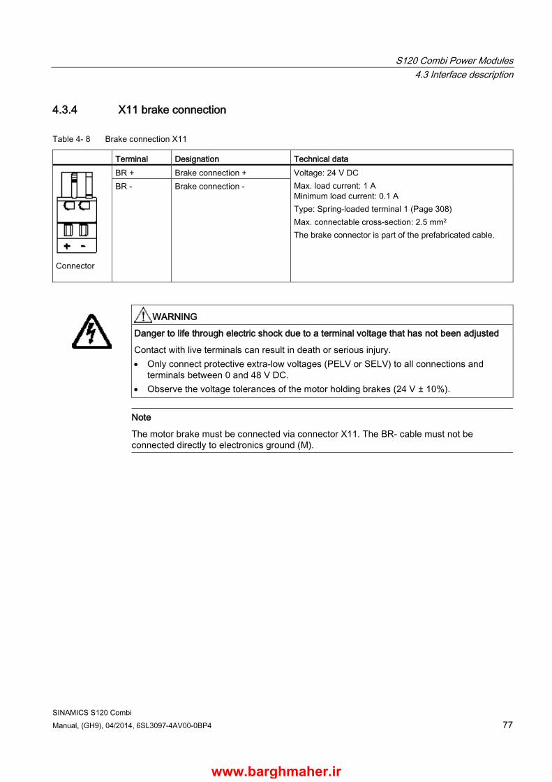
S120 Combi Power Modules 4.3 Interface description
SINAMICS S120 Combi Manual, (GH9), 04/2014, 6SL3097-4AV00-0BP4 77
4.3.4 X11 brake connection
Table 4- 8 Brake connection X11
Terminal Designation Technical data
Connector
BR + Brake connection + Voltage: 24 V DC Max. load current: 1 A Minimum load current: 0.1 A Type: Spring-loaded terminal 1 (Page 308) Max. connectable cross-section: 2.5 mm2 The brake connector is part of the prefabricated cable.
BR - Brake connection -
WARNING
Danger to life through electric shock due to a terminal voltage that has not been adjusted
Contact with live terminals can result in death or serious injury. • Only connect protective extra-low voltages (PELV or SELV) to all connections and
terminals between 0 and 48 V DC. • Observe the voltage tolerances of the motor holding brakes (24 V ± 10%).
Note
The motor brake must be connected via connector X11. The BR- cable must not be connected directly to electronics ground (M).
www.barghmaher.ir

S120 Combi Power Modules 4.3 Interface description
SINAMICS S120 Combi 78 Manual, (GH9), 04/2014, 6SL3097-4AV00-0BP4
4.3.5 X12/X13 fan connection
Table 4- 9 X12/X13 connection of the external fan unit
Terminal Designation Technical data
1 Ground Current-carrying capacity (24 V): 2 x 1 A or 1 x 2 A Type: Screw terminal 1 (Page 309) Max. connectable cross-section: 1.5 mm2 Tightening torque: 0.22 … 0.5 Nm
2 Fan monitoring 3 +24 V 4 Ground
Note Connecting a fan assembly with 2-core cables
When connecting a customer's own fan assembly using 2-core cables, an error message appears regarding the fan. • Connect terminals 1 and 2 with a jumper.
Note
When connecting a customer's own fan assembly using 3-core cables, the white core (high fault signal = fault) can be connected to terminal 2.
www.barghmaher.ir
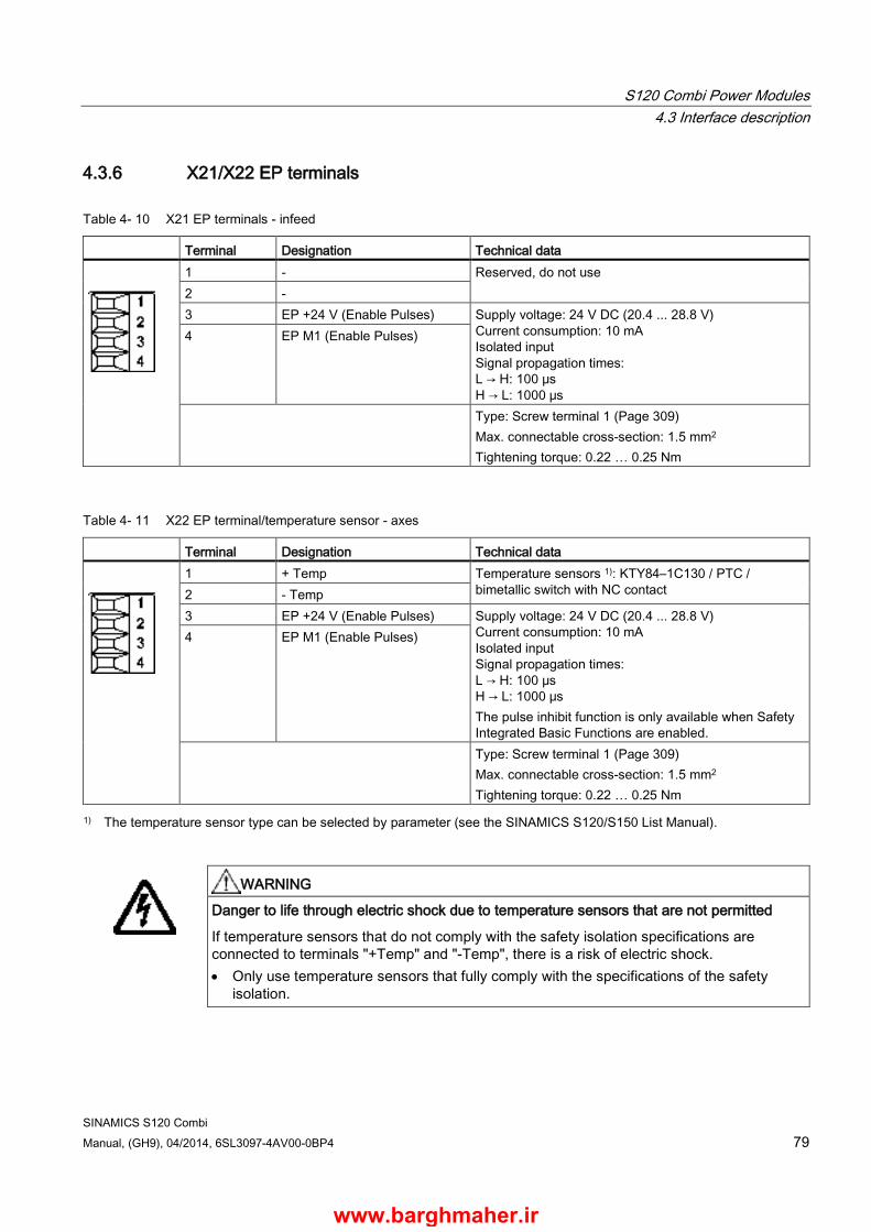
S120 Combi Power Modules 4.3 Interface description
SINAMICS S120 Combi Manual, (GH9), 04/2014, 6SL3097-4AV00-0BP4 79
4.3.6 X21/X22 EP terminals
Table 4- 10 X21 EP terminals - infeed
Terminal Designation Technical data
1 - Reserved, do not use 2 - 3 EP +24 V (Enable Pulses) Supply voltage: 24 V DC (20.4 ... 28.8 V)
Current consumption: 10 mA Isolated input Signal propagation times: L → H: 100 μs H → L: 1000 μs
4 EP M1 (Enable Pulses)
Type: Screw terminal 1 (Page 309) Max. connectable cross-section: 1.5 mm2 Tightening torque: 0.22 … 0.25 Nm
Table 4- 11 X22 EP terminal/temperature sensor - axes
Terminal Designation Technical data
1 + Temp Temperature sensors 1): KTY84–1C130 / PTC / bimetallic switch with NC contact 2 - Temp
3 EP +24 V (Enable Pulses) Supply voltage: 24 V DC (20.4 ... 28.8 V) Current consumption: 10 mA Isolated input Signal propagation times: L → H: 100 μs H → L: 1000 μs The pulse inhibit function is only available when Safety Integrated Basic Functions are enabled.
4 EP M1 (Enable Pulses)
Type: Screw terminal 1 (Page 309) Max. connectable cross-section: 1.5 mm2 Tightening torque: 0.22 … 0.25 Nm
1) The temperature sensor type can be selected by parameter (see the SINAMICS S120/S150 List Manual).
WARNING
Danger to life through electric shock due to temperature sensors that are not permitted
If temperature sensors that do not comply with the safety isolation specifications are connected to terminals "+Temp" and "-Temp", there is a risk of electric shock. • Only use temperature sensors that fully comply with the specifications of the safety
isolation.
www.barghmaher.ir
S120 Combi Power Modules 4.3 Interface description
SINAMICS S120 Combi 80 Manual, (GH9), 04/2014, 6SL3097-4AV00-0BP4
NOTICE
Damage due to overheating, caused by a KTY temperature sensor that has been incorrectly connected
If the KTY temperature sensor was not connected with the correct polarity, motor overheating may not be detected. • Connect the KTY temperature sensor with the correct polarity.
Note
The function of the EP terminals is only available when Safety Integrated Basic Functions are enabled.
Note
The temperature sensor input is not needed if the motors feature an integrated DRIVE-CLiQ interface or if temperature values are detected by means of a different module (SMC, SME).
www.barghmaher.ir
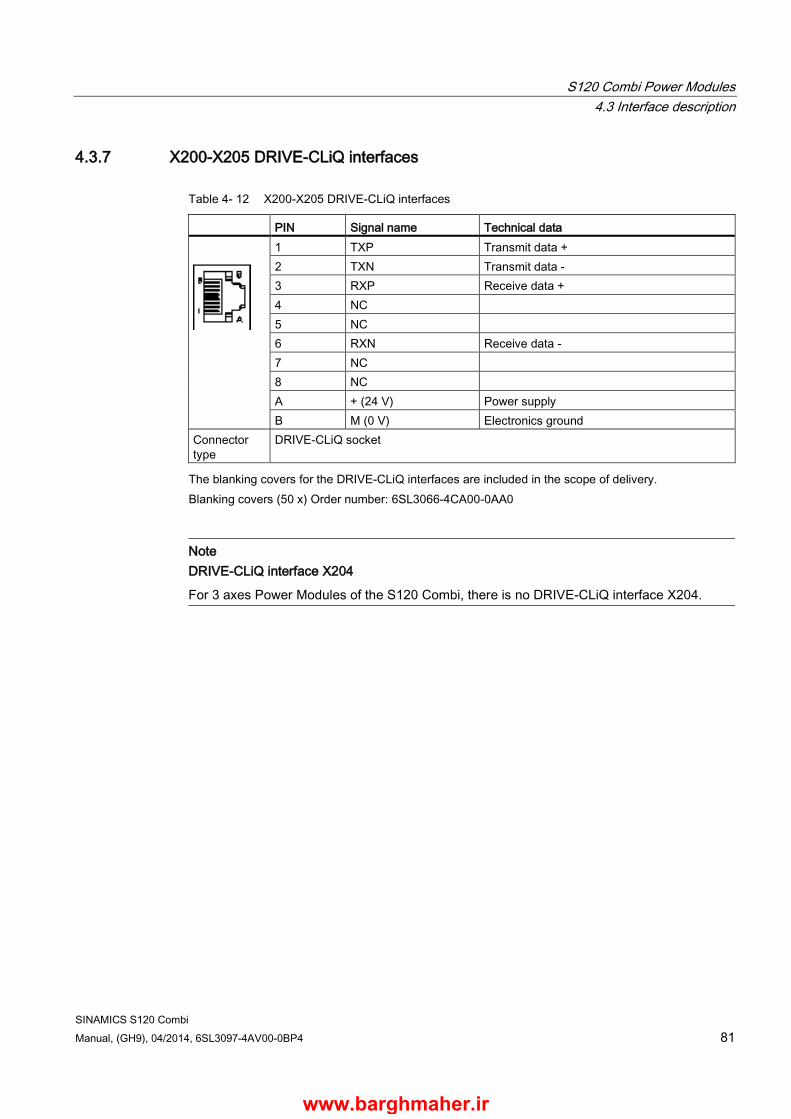
S120 Combi Power Modules 4.3 Interface description
SINAMICS S120 Combi Manual, (GH9), 04/2014, 6SL3097-4AV00-0BP4 81
4.3.7 X200-X205 DRIVE-CLiQ interfaces
Table 4- 12 X200-X205 DRIVE-CLiQ interfaces
PIN Signal name Technical data
1 TXP Transmit data + 2 TXN Transmit data - 3 RXP Receive data + 4 NC 5 NC 6 RXN Receive data - 7 NC 8 NC A + (24 V) Power supply B M (0 V) Electronics ground
Connector type
DRIVE-CLiQ socket
The blanking covers for the DRIVE-CLiQ interfaces are included in the scope of delivery. Blanking covers (50 x) Order number: 6SL3066-4CA00-0AA0
Note DRIVE-CLiQ interface X204
For 3 axes Power Modules of the S120 Combi, there is no DRIVE-CLiQ interface X204.
www.barghmaher.ir
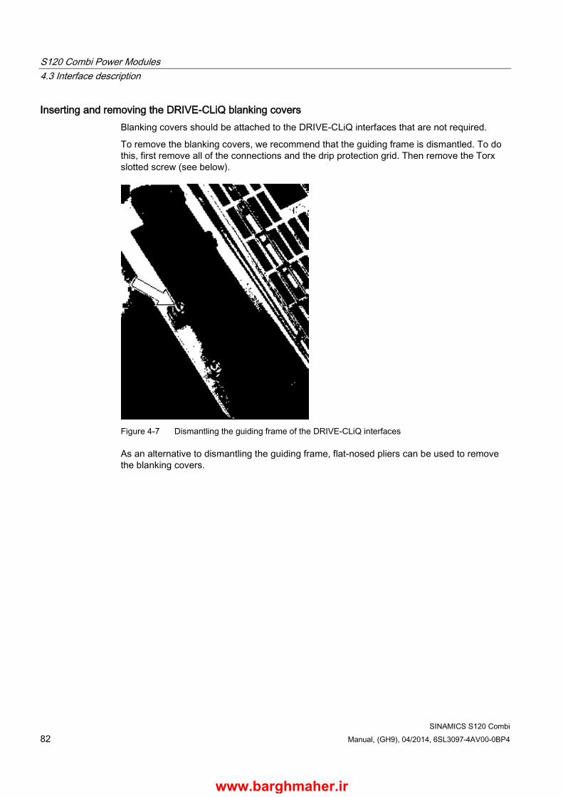
S120 Combi Power Modules 4.3 Interface description
SINAMICS S120 Combi 82 Manual, (GH9), 04/2014, 6SL3097-4AV00-0BP4
Inserting and removing the DRIVE-CLiQ blanking covers Blanking covers should be attached to the DRIVE-CLiQ interfaces that are not required.
To remove the blanking covers, we recommend that the guiding frame is dismantled. To do this, first remove all of the connections and the drip protection grid. Then remove the Torx slotted screw (see below).
Figure 4-7 Dismantling the guiding frame of the DRIVE-CLiQ interfaces
As an alternative to dismantling the guiding frame, flat-nosed pliers can be used to remove the blanking covers.
www.barghmaher.ir
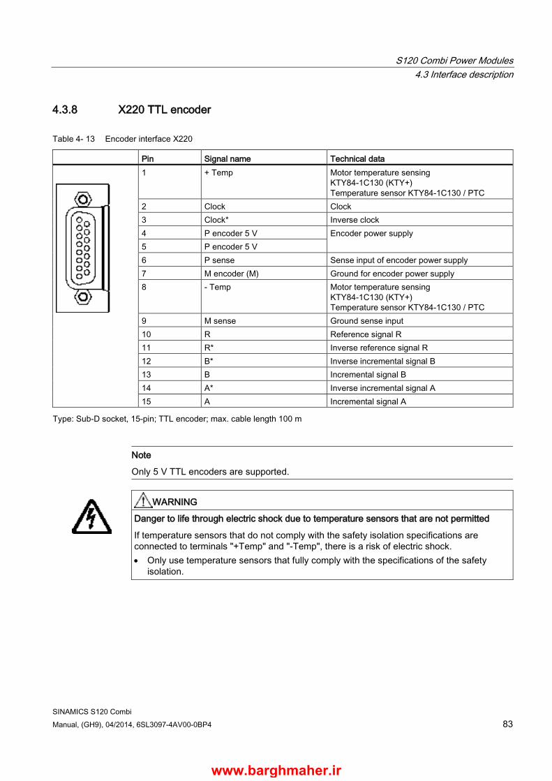
S120 Combi Power Modules 4.3 Interface description
SINAMICS S120 Combi Manual, (GH9), 04/2014, 6SL3097-4AV00-0BP4 83
4.3.8 X220 TTL encoder
Table 4- 13 Encoder interface X220
Pin Signal name Technical data
1 + Temp Motor temperature sensing KTY84-1C130 (KTY+) Temperature sensor KTY84-1C130 / PTC
2 Clock Clock 3 Clock* Inverse clock 4 P encoder 5 V Encoder power supply 5 P encoder 5 V 6 P sense Sense input of encoder power supply 7 M encoder (M) Ground for encoder power supply 8 - Temp Motor temperature sensing
KTY84-1C130 (KTY+) Temperature sensor KTY84-1C130 / PTC
9 M sense Ground sense input 10 R Reference signal R 11 R* Inverse reference signal R 12 B* Inverse incremental signal B 13 B Incremental signal B 14 A* Inverse incremental signal A 15 A Incremental signal A
Type: Sub-D socket, 15-pin; TTL encoder; max. cable length 100 m
Note
Only 5 V TTL encoders are supported.
WARNING
Danger to life through electric shock due to temperature sensors that are not permitted
If temperature sensors that do not comply with the safety isolation specifications are connected to terminals "+Temp" and "-Temp", there is a risk of electric shock. • Only use temperature sensors that fully comply with the specifications of the safety
isolation.
www.barghmaher.ir

S120 Combi Power Modules 4.3 Interface description
SINAMICS S120 Combi 84 Manual, (GH9), 04/2014, 6SL3097-4AV00-0BP4
Table 4- 14 Technical data of the encoder system supply
Encoder system supply Unit Value Voltage VDC 5 (with or without remote sense)1) Current ADC 0,35 Encoder frequency that can be evaluated (fencoder) kHz ≤ 300 1) A controller compares the encoder system supply voltage - sensed via the remote sense cables - with the reference
supply voltage of the encoder system, and adjusts the supply voltage for the encoder system at the output of the drive module until the required supply voltage is obtained directly at the encoder system.
Table 4- 15 Specification of TTL encoder systems that can be connected
Parameter Designation Threshold Min. Max. Unit
Signal level, high1) UHdiff 2 5 V Signal level, low1) ULdiff -5 -2 V Signal frequency fS - 300 kHz Edge clearance tmin 100 - ns "Zero pulse inactive time" (before and after A=B=high)
tLo 640 (tALo-BHi - tHi)/22) ns
"Zero pulse active time" (while A=B=high and beyond) 3)
tHi 640 tALo-BHi - 2*tLo2) ns
1) Other signal levels according to the RS 422 standard. 2) tALo-BHi is not a specified value, but is the time between the falling edge of track A and the next but one rising edge of
track B. 3) Further information on setting the "Zero pulse active time" can be found in the following:
References: SINAMICS S120 Function Manual (FH1), tolerant encoder monitoring for SMC30
www.barghmaher.ir
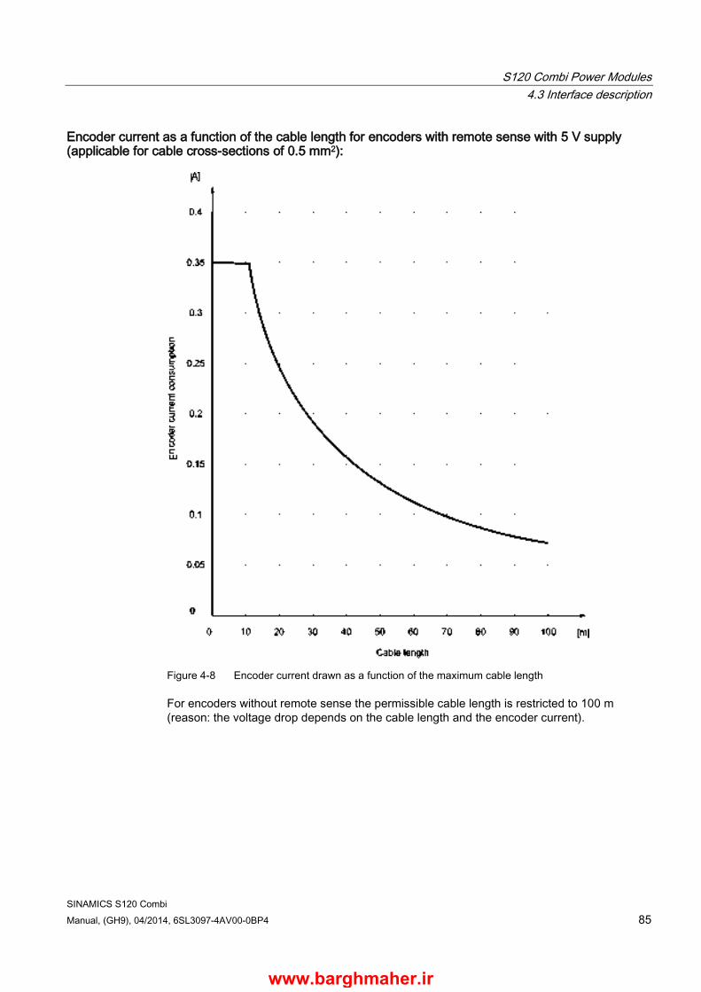
S120 Combi Power Modules 4.3 Interface description
SINAMICS S120 Combi Manual, (GH9), 04/2014, 6SL3097-4AV00-0BP4 85
Encoder current as a function of the cable length for encoders with remote sense with 5 V supply (applicable for cable cross-sections of 0.5 mm2):
Figure 4-8 Encoder current drawn as a function of the maximum cable length
For encoders without remote sense the permissible cable length is restricted to 100 m (reason: the voltage drop depends on the cable length and the encoder current).
www.barghmaher.ir
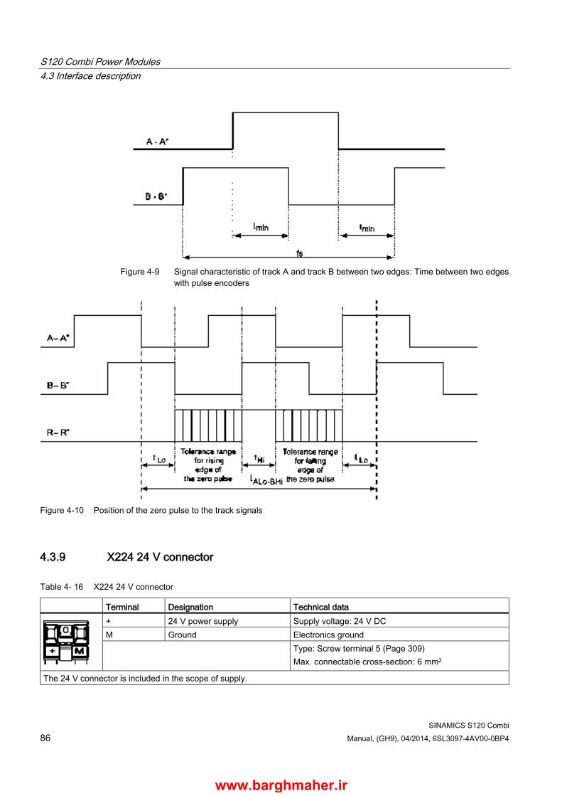
S120 Combi Power Modules 4.3 Interface description
SINAMICS S120 Combi 86 Manual, (GH9), 04/2014, 6SL3097-4AV00-0BP4
Figure 4-9 Signal characteristic of track A and track B between two edges: Time between two edges
with pulse encoders
Figure 4-10 Position of the zero pulse to the track signals
4.3.9 X224 24 V connector
Table 4- 16 X224 24 V connector
Terminal Designation Technical data
+ 24 V power supply Supply voltage: 24 V DC M Ground Electronics ground Type: Screw terminal 5 (Page 309)
Max. connectable cross-section: 6 mm2
The 24 V connector is included in the scope of supply.
www.barghmaher.ir

S120 Combi Power Modules 4.4 Connection examples
SINAMICS S120 Combi Manual, (GH9), 04/2014, 6SL3097-4AV00-0BP4 87
4.4 Connection examples
Figure 4-11 Connection example for an S120 Combi 3 axis Power Module with a motor holding brake
www.barghmaher.ir
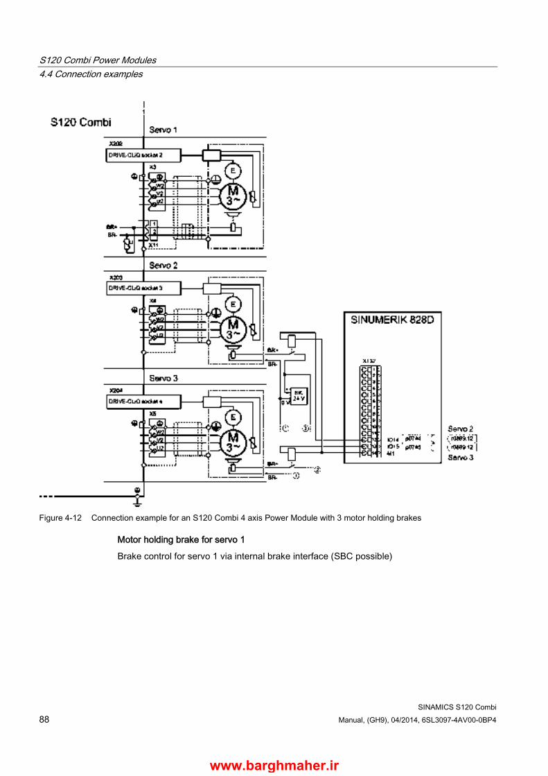
S120 Combi Power Modules 4.4 Connection examples
SINAMICS S120 Combi 88 Manual, (GH9), 04/2014, 6SL3097-4AV00-0BP4
Figure 4-12 Connection example for an S120 Combi 4 axis Power Module with 3 motor holding brakes
Motor holding brake for servo 1
Brake control for servo 1 via internal brake interface (SBC possible)
www.barghmaher.ir
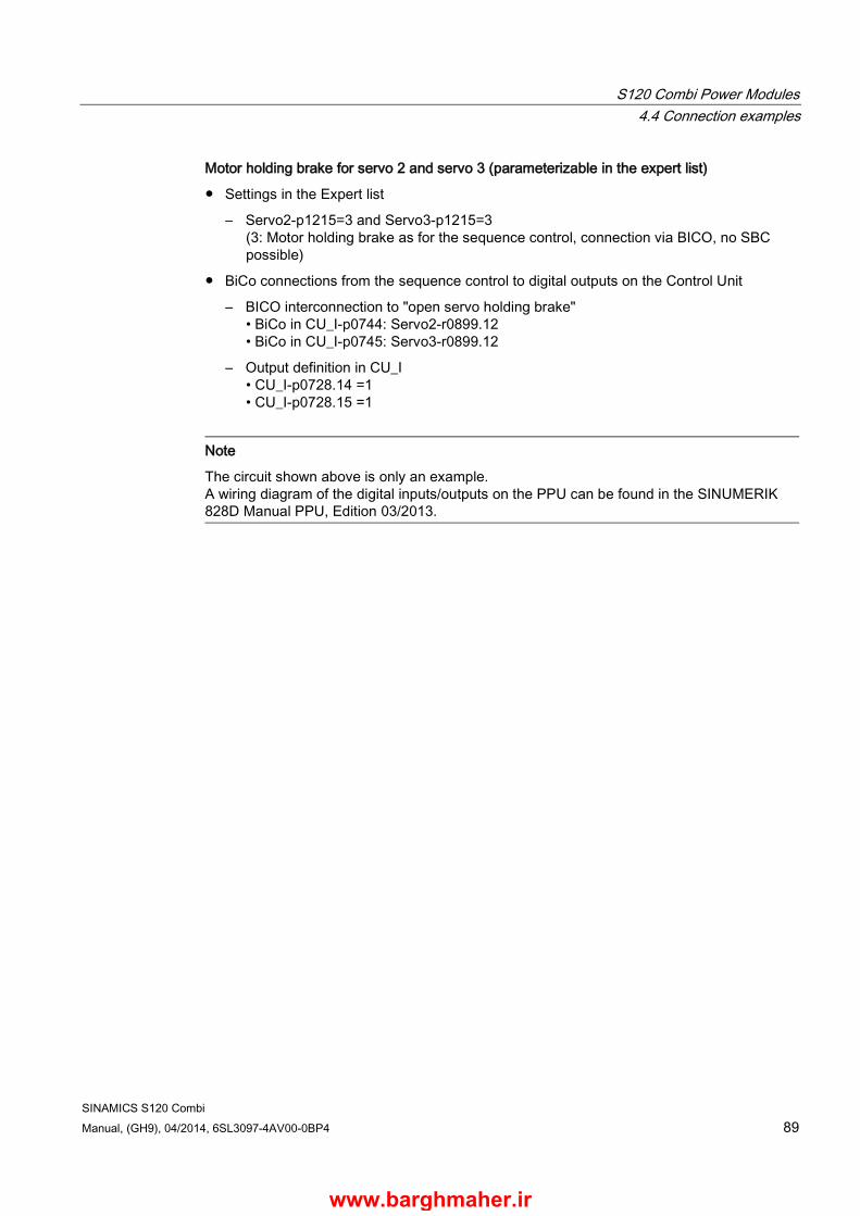
S120 Combi Power Modules 4.4 Connection examples
SINAMICS S120 Combi Manual, (GH9), 04/2014, 6SL3097-4AV00-0BP4 89
Motor holding brake for servo 2 and servo 3 (parameterizable in the expert list)
● Settings in the Expert list
– Servo2-p1215=3 and Servo3-p1215=3 (3: Motor holding brake as for the sequence control, connection via BICO, no SBC possible)
● BiCo connections from the sequence control to digital outputs on the Control Unit
– BICO interconnection to "open servo holding brake" • BiCo in CU_I-p0744: Servo2-r0899.12 • BiCo in CU_I-p0745: Servo3-r0899.12
– Output definition in CU_I • CU_I-p0728.14 =1 • CU_I-p0728.15 =1
Note
The circuit shown above is only an example. A wiring diagram of the digital inputs/outputs on the PPU can be found in the SINUMERIK 828D Manual PPU, Edition 03/2013.
www.barghmaher.ir
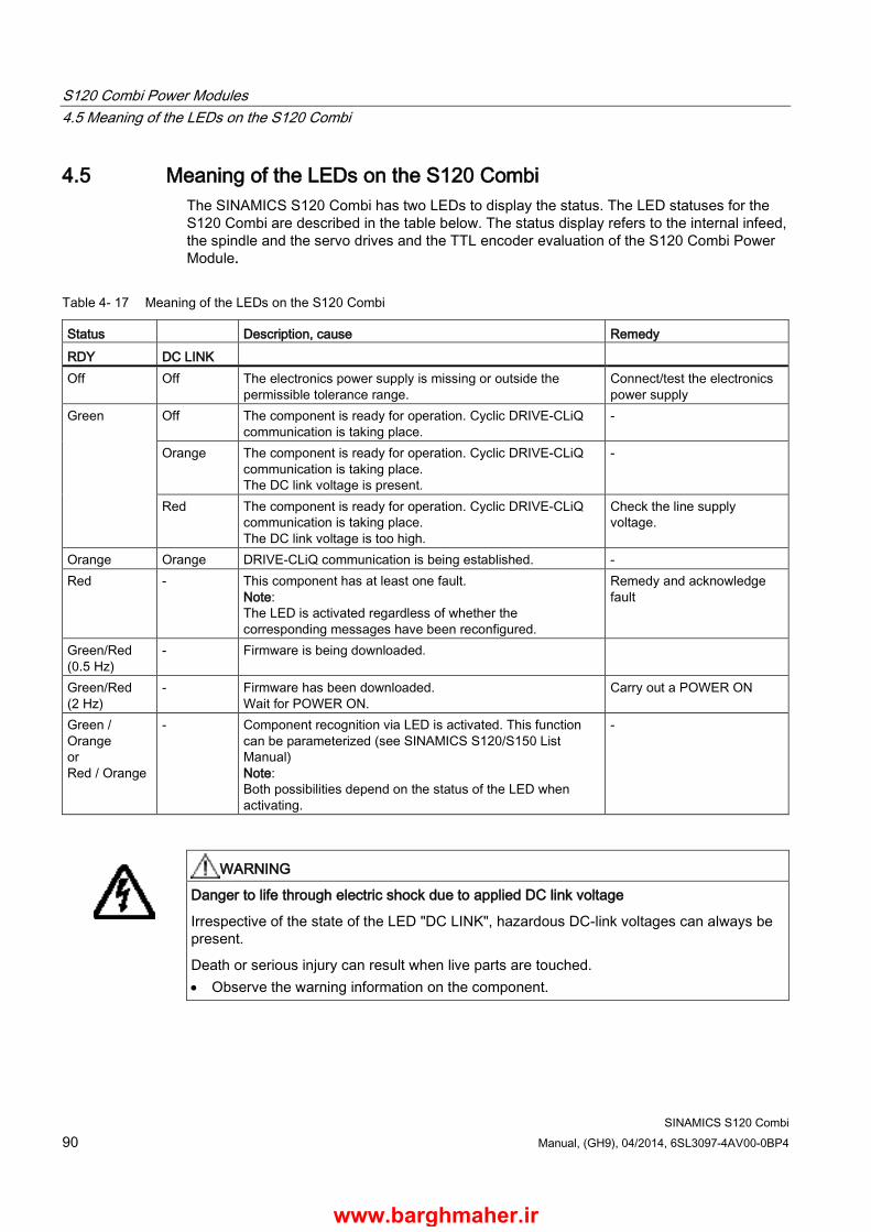
S120 Combi Power Modules 4.5 Meaning of the LEDs on the S120 Combi
SINAMICS S120 Combi 90 Manual, (GH9), 04/2014, 6SL3097-4AV00-0BP4
4.5 Meaning of the LEDs on the S120 Combi The SINAMICS S120 Combi has two LEDs to display the status. The LED statuses for the S120 Combi are described in the table below. The status display refers to the internal infeed, the spindle and the servo drives and the TTL encoder evaluation of the S120 Combi Power Module.
Table 4- 17 Meaning of the LEDs on the S120 Combi
Status Description, cause Remedy RDY DC LINK Off Off The electronics power supply is missing or outside the
permissible tolerance range. Connect/test the electronics power supply
Green Off The component is ready for operation. Cyclic DRIVE-CLiQ communication is taking place.
-
Orange The component is ready for operation. Cyclic DRIVE-CLiQ communication is taking place. The DC link voltage is present.
-
Red The component is ready for operation. Cyclic DRIVE-CLiQ communication is taking place. The DC link voltage is too high.
Check the line supply voltage.
Orange Orange DRIVE-CLiQ communication is being established. - Red - This component has at least one fault.
Note: The LED is activated regardless of whether the corresponding messages have been reconfigured.
Remedy and acknowledge fault
Green/Red (0.5 Hz)
- Firmware is being downloaded.
Green/Red (2 Hz)
- Firmware has been downloaded. Wait for POWER ON.
Carry out a POWER ON
Green / Orange or Red / Orange
- Component recognition via LED is activated. This function can be parameterized (see SINAMICS S120/S150 List Manual) Note: Both possibilities depend on the status of the LED when activating.
-
WARNING
Danger to life through electric shock due to applied DC link voltage
Irrespective of the state of the LED "DC LINK", hazardous DC-link voltages can always be present.
Death or serious injury can result when live parts are touched. • Observe the warning information on the component.
www.barghmaher.ir

S120 Combi Power Modules 4.5 Meaning of the LEDs on the S120 Combi
SINAMICS S120 Combi Manual, (GH9), 04/2014, 6SL3097-4AV00-0BP4 91
Cause and rectification of faults
The following reference material contains information about the cause of faults and how they are rectified:
SINAMICS S120 Function Manual Drive Functions (FH1)
SINUMERIK 828D Turning and Milling Commissioning Manual
SINUMERIK 840D sl commissioning CNC
www.barghmaher.ir
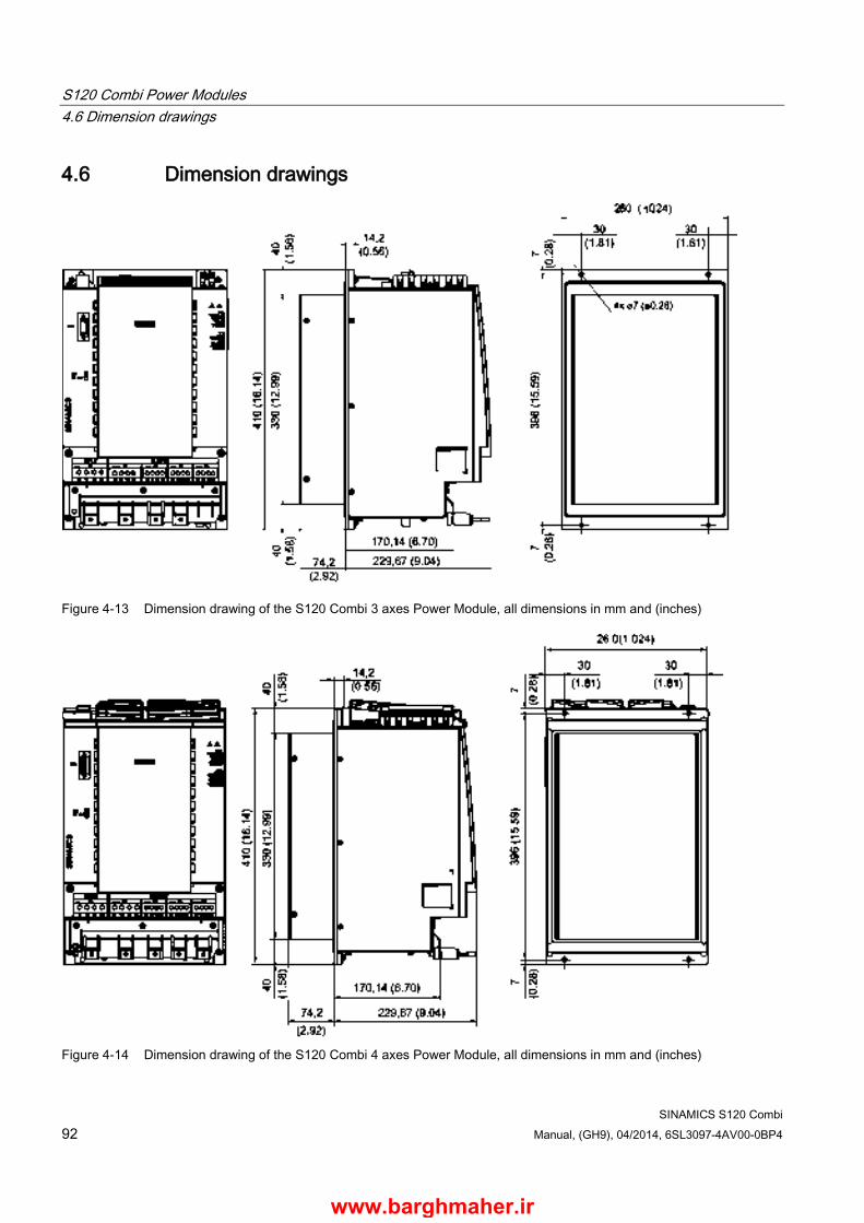
S120 Combi Power Modules 4.6 Dimension drawings
SINAMICS S120 Combi 92 Manual, (GH9), 04/2014, 6SL3097-4AV00-0BP4
4.6 Dimension drawings
Figure 4-13 Dimension drawing of the S120 Combi 3 axes Power Module, all dimensions in mm and (inches)
Figure 4-14 Dimension drawing of the S120 Combi 4 axes Power Module, all dimensions in mm and (inches)
www.barghmaher.ir

S120 Combi Power Modules 4.7 Installation
SINAMICS S120 Combi Manual, (GH9), 04/2014, 6SL3097-4AV00-0BP4 93
4.7 Installation
4.7.1 Drilling patterns and installation cut-outs
Preparing the mounting panel The installation cut-outs shown below are for any S120 Combi Power Module and the external fan unit.
The drilling patterns differ by the number and width of the expansion axes. Select the appropriate drilling pattern corresponding to your individual design.
www.barghmaher.ir
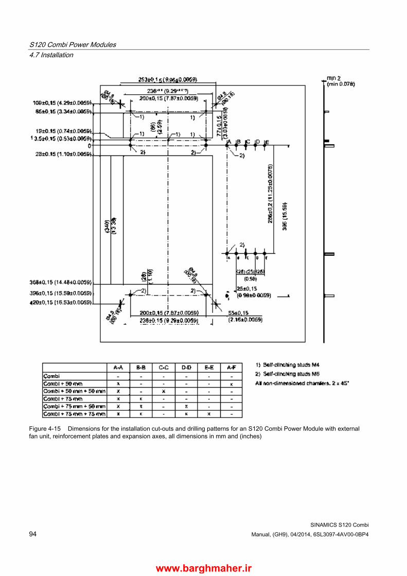
S120 Combi Power Modules 4.7 Installation
SINAMICS S120 Combi 94 Manual, (GH9), 04/2014, 6SL3097-4AV00-0BP4
Figure 4-15 Dimensions for the installation cut-outs and drilling patterns for an S120 Combi Power Module with external fan unit, reinforcement plates and expansion axes, all dimensions in mm and (inches)
www.barghmaher.ir
S120 Combi Power Modules 4.7 Installation
SINAMICS S120 Combi Manual, (GH9), 04/2014, 6SL3097-4AV00-0BP4 95
4.7.2 Installing the reinforcement plates
4.7.2.1 Description The reinforcement plates for the S120 Combi fulfill the following functions:
● Air is routed in a specific way to dissipate the heat of the external heat sink
● They stabilize the mounting panel
The reinforcement plates must always mounted. They should be installed at the rear of the mounting panel or the control cabinet before installing the S120 Combi Power Module and the external fan unit.
Note
The reinforcement plates are not included in the scope of delivery of the S120 Combi. They must be separately ordered (order number 6SL3161-1LP00-0AA0).
www.barghmaher.ir
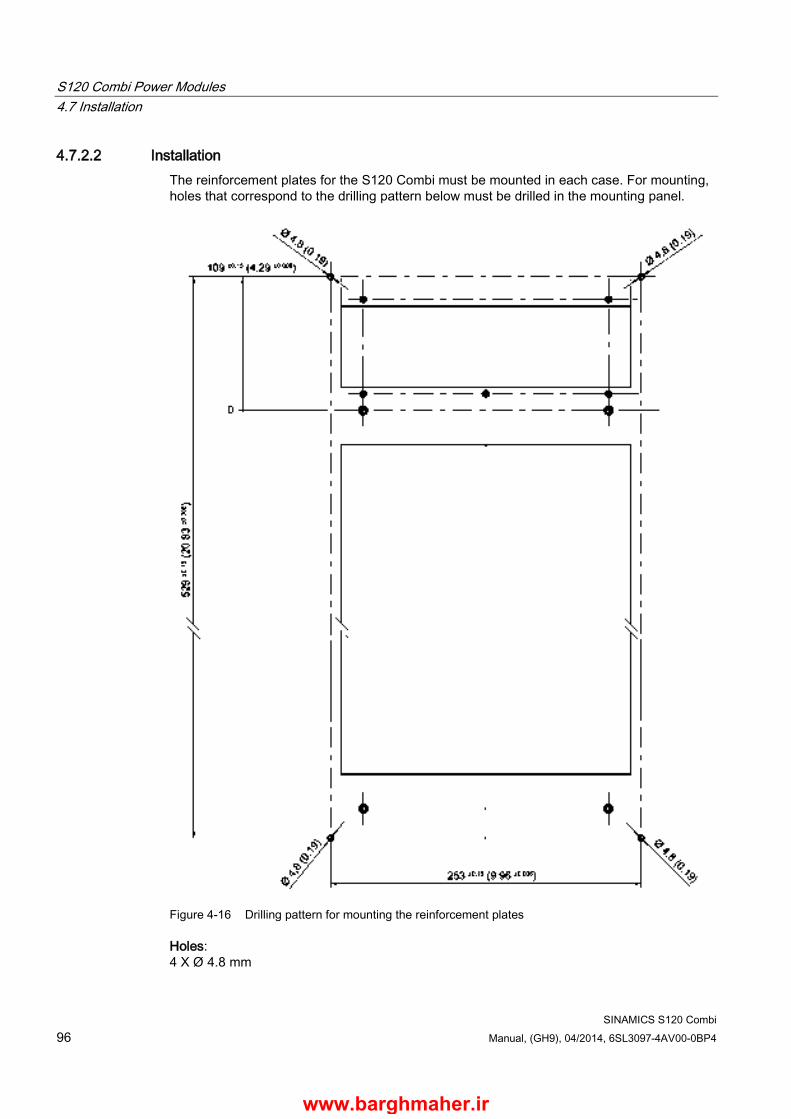
S120 Combi Power Modules 4.7 Installation
SINAMICS S120 Combi 96 Manual, (GH9), 04/2014, 6SL3097-4AV00-0BP4
4.7.2.2 Installation The reinforcement plates for the S120 Combi must be mounted in each case. For mounting, holes that correspond to the drilling pattern below must be drilled in the mounting panel.
Figure 4-16 Drilling pattern for mounting the reinforcement plates
Holes: 4 X Ø 4.8 mm
www.barghmaher.ir
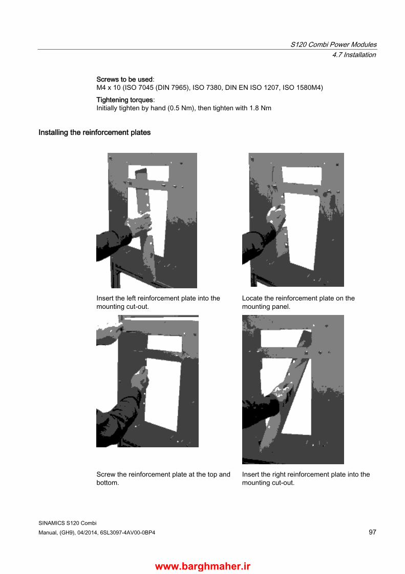
S120 Combi Power Modules 4.7 Installation
SINAMICS S120 Combi Manual, (GH9), 04/2014, 6SL3097-4AV00-0BP4 97
Screws to be used: M4 x 10 (ISO 7045 (DIN 7965), ISO 7380, DIN EN ISO 1207, ISO 1580M4)
Tightening torques: Initially tighten by hand (0.5 Nm), then tighten with 1.8 Nm
Installing the reinforcement plates
Insert the left reinforcement plate into the mounting cut-out.
Locate the reinforcement plate on the mounting panel.
Screw the reinforcement plate at the top and bottom.
Insert the right reinforcement plate into the mounting cut-out.
www.barghmaher.ir

S120 Combi Power Modules 4.7 Installation
SINAMICS S120 Combi 98 Manual, (GH9), 04/2014, 6SL3097-4AV00-0BP4
Locate the reinforcement plate on the mounting panel.
Screw the reinforcement plate at the top and bottom.
When installing the reinforcement plates, it is important to observe alignment.
Figure 4-17 Alignment of the reinforcement plates
www.barghmaher.ir

S120 Combi Power Modules 4.7 Installation
SINAMICS S120 Combi Manual, (GH9), 04/2014, 6SL3097-4AV00-0BP4 99
① Reinforcement plates ② Holes to remove/tighten the screws on the air baffle plate of the S120 Combi ③ M4x10 screws
Figure 4-18 Installed reinforcement plates: View from the front and from the rear
CAUTION
Physical injury due to incorrect mounting of the reinforcement plates
If the reinforcing plates are incorrectly mounted, this can result in an excessively high heat sink temperature and cause the S120 Combi Power Module to prematurely trip.
Contact with hot parts may cause you to suffer a burn injury. • Follow the installation instructions when mounting the reinforcement plates.
4.7.2.3 Technical data 6SL3161-1LP00-0AA0 Unit Value Weight (2 units) kg 1.5 Dimensions (W x H x D) mm 150 x 57.5 x 750
www.barghmaher.ir

S120 Combi Power Modules 4.7 Installation
SINAMICS S120 Combi 100 Manual, (GH9), 04/2014, 6SL3097-4AV00-0BP4
4.7.3 Installing an S120 Combi Power Module
Installation steps
Note Seal
Always use a new, appropriate seal (see Chapter Installing seals on the S120 Combi (Page 338) as well as Spare parts (Page 324)) when reassembling an S120 Combi Power Module.
The old seal or any seal remnants must be completely removed from the S120 Combi as well as from the control cabinet before reassembly. Make sure that the sealing surfaces are free of grease and dirt.
1. Mount the self-clinching flush head studs M6.
2. Install the S120 Combi Power Module.
3. Firstly tighten the M6 nuts by hand (0.5 Nm).
4. Tighten the nuts in the specified sequence (1 to 4) with 10 Nm.
www.barghmaher.ir
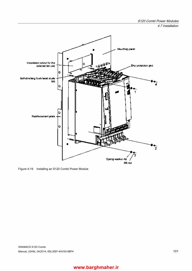
S120 Combi Power Modules 4.7 Installation
SINAMICS S120 Combi Manual, (GH9), 04/2014, 6SL3097-4AV00-0BP4 101
Figure 4-19 Installing an S120 Combi Power Module
www.barghmaher.ir
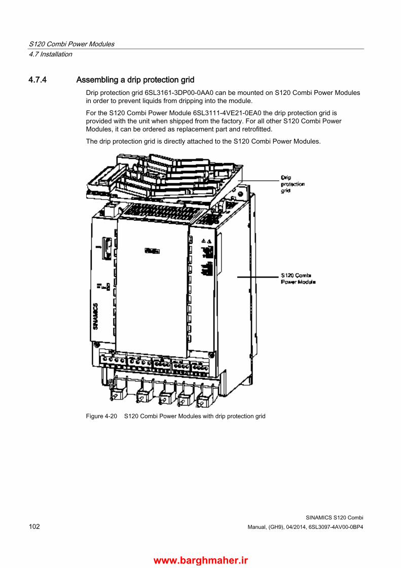
S120 Combi Power Modules 4.7 Installation
SINAMICS S120 Combi 102 Manual, (GH9), 04/2014, 6SL3097-4AV00-0BP4
4.7.4 Assembling a drip protection grid Drip protection grid 6SL3161-3DP00-0AA0 can be mounted on S120 Combi Power Modules in order to prevent liquids from dripping into the module.
For the S120 Combi Power Module 6SL3111-4VE21-0EA0 the drip protection grid is provided with the unit when shipped from the factory. For all other S120 Combi Power Modules, it can be ordered as replacement part and retrofitted.
The drip protection grid is directly attached to the S120 Combi Power Modules.
Figure 4-20 S120 Combi Power Modules with drip protection grid
www.barghmaher.ir

S120 Combi Power Modules 4.7 Installation
SINAMICS S120 Combi Manual, (GH9), 04/2014, 6SL3097-4AV00-0BP4 103
4.7.5 Mounting an external fan module
4.7.5.1 Description The S120 Combi provides an integrated fan control and supply for an external 24 V fan unit. The fan unit is connected via interface X12/X13. The outputs are designed for a maximum total current of 2 A and are short-circuit and ground-fault proof.
The following functions are available when using the external fan unit:
● Operating hours counter (see SINAMICS S120/S150 List Manual)
● Setting the maximum operating time (see SINAMICS S120/S150 List Manual)
● Evaluating fault signals
4.7.5.2 Overview The external fan unit comprises the following components:
● Fan cradle with seal for installation in the control cabinet
● Connection cables with 4-pin connector
● Double fan
● Fan support plate
● Air baffle plate
www.barghmaher.ir
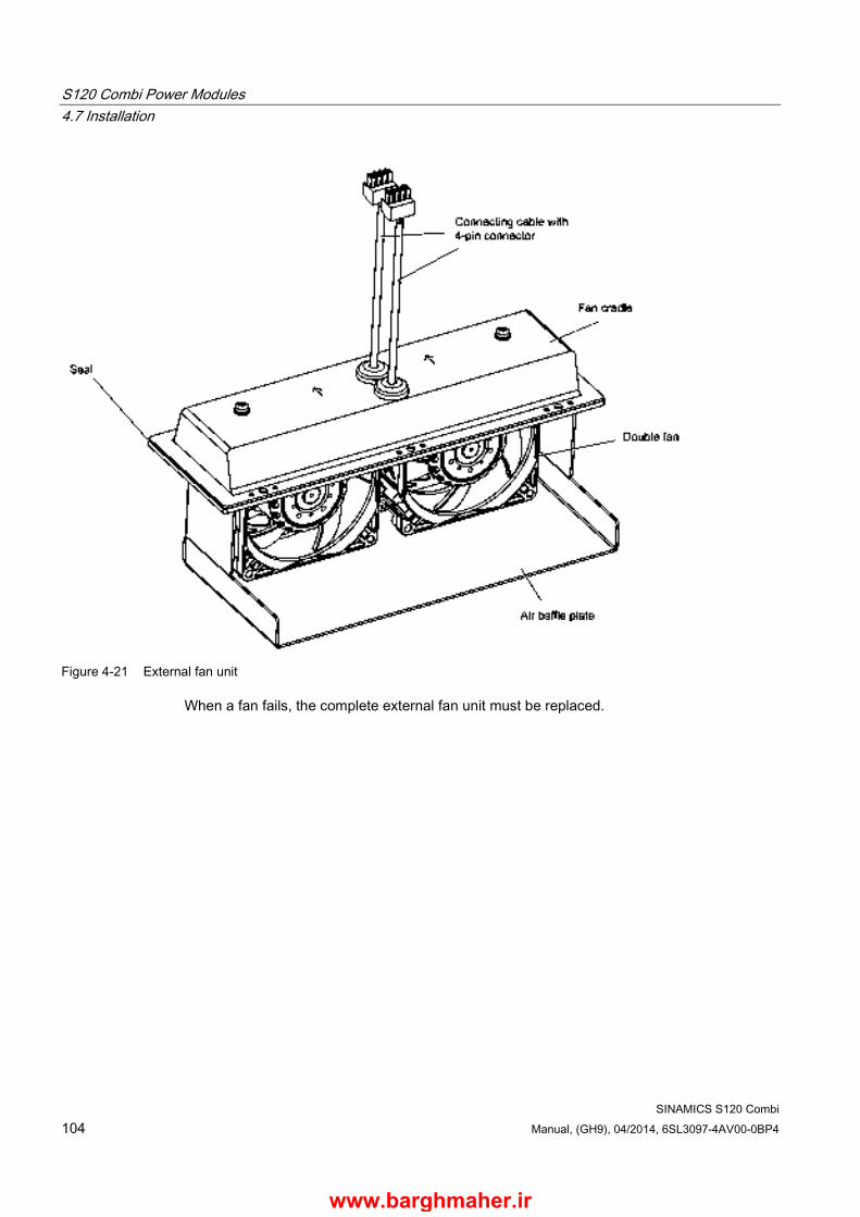
S120 Combi Power Modules 4.7 Installation
SINAMICS S120 Combi 104 Manual, (GH9), 04/2014, 6SL3097-4AV00-0BP4
Figure 4-21 External fan unit
When a fan fails, the complete external fan unit must be replaced.
www.barghmaher.ir

S120 Combi Power Modules 4.7 Installation
SINAMICS S120 Combi Manual, (GH9), 04/2014, 6SL3097-4AV00-0BP4 105
4.7.5.3 Dimension drawing
Figure 4-22 Dimension drawing of the external fan unit, all dimensions in mm and (inches)
www.barghmaher.ir
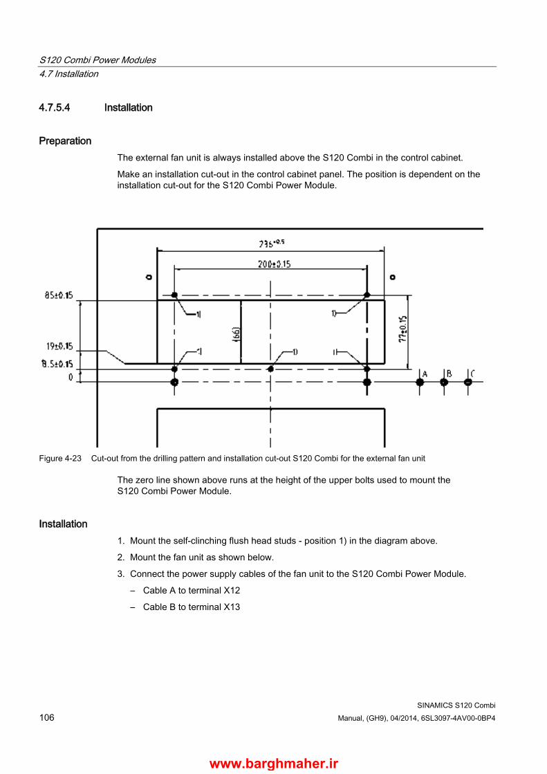
S120 Combi Power Modules 4.7 Installation
SINAMICS S120 Combi 106 Manual, (GH9), 04/2014, 6SL3097-4AV00-0BP4
4.7.5.4 Installation
Preparation The external fan unit is always installed above the S120 Combi in the control cabinet.
Make an installation cut-out in the control cabinet panel. The position is dependent on the installation cut-out for the S120 Combi Power Module.
Figure 4-23 Cut-out from the drilling pattern and installation cut-out S120 Combi for the external fan unit
The zero line shown above runs at the height of the upper bolts used to mount the S120 Combi Power Module.
Installation 1. Mount the self-clinching flush head studs - position 1) in the diagram above.
2. Mount the fan unit as shown below.
3. Connect the power supply cables of the fan unit to the S120 Combi Power Module.
– Cable A to terminal X12
– Cable B to terminal X13
www.barghmaher.ir
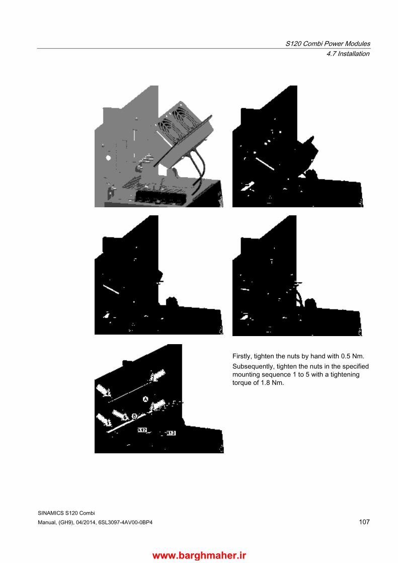
S120 Combi Power Modules 4.7 Installation
SINAMICS S120 Combi Manual, (GH9), 04/2014, 6SL3097-4AV00-0BP4 107
Firstly, tighten the nuts by hand with 0.5 Nm. Subsequently, tighten the nuts in the specified mounting sequence 1 to 5 with a tightening torque of 1.8 Nm.
www.barghmaher.ir
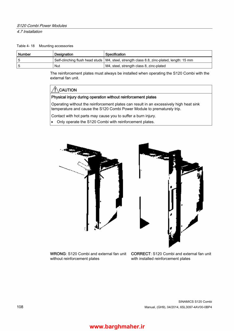
S120 Combi Power Modules 4.7 Installation
SINAMICS S120 Combi 108 Manual, (GH9), 04/2014, 6SL3097-4AV00-0BP4
Table 4- 18 Mounting accessories
Number Designation Specification 5 Self-clinching flush head studs M4, steel, strength class 8.8, zinc-plated, length: 15 mm 5 Nut M4, steel, strength class 8, zinc-plated
The reinforcement plates must always be installed when operating the S120 Combi with the external fan unit.
CAUTION
Physical injury during operation without reinforcement plates
Operating without the reinforcement plates can result in an excessively high heat sink temperature and cause the S120 Combi Power Module to prematurely trip.
Contact with hot parts may cause you to suffer a burn injury. • Only operate the S120 Combi with reinforcement plates.
WRONG: S120 Combi and external fan unit without reinforcement plates
CORRECT: S120 Combi and external fan unit with installed reinforcement plates
www.barghmaher.ir
S120 Combi Power Modules 4.7 Installation
SINAMICS S120 Combi Manual, (GH9), 04/2014, 6SL3097-4AV00-0BP4 109
4.7.5.5 Technical data
Table 4- 19 Technical data of the external fan unit
6SL3161-0EP00-0AA0 Unit Value Input voltage VDC 20.4 … 28.8 Power consumption W 18 Electronics current drawn at 24 V DC A 0.8 Volumetric rate of air flow m3/h 290 Service life h 50000 at 55 °C Dimensions (W x H x D) mm 258 x 104 x 86 Weight kg 1.5 Degree of protection IP54
www.barghmaher.ir
S120 Combi Power Modules 4.8 Electrical connection
SINAMICS S120 Combi 110 Manual, (GH9), 04/2014, 6SL3097-4AV00-0BP4
4.8 Electrical connection
4.8.1 Stripped length for the line supply and power cables Non-prefabricated MOTION-CONNECT power cables must be appropriately prepared before being connected to the S120 Combi.
Note Special issue for UL applications
For UL applications, use 60/75 °C copper wires/conductors.
Cables without connection cables for the motor holding brake 1. Cut the cable jacket to dimension A from the table below
2. Strip the single cores U, V, W and PE and crimp on end sleeves with insulation support
Cables with connection cables for the motor holding brake 1. Cut the cable jacket to 250 ± 5 mm
2. Cut the single cores U, V, W and PE to dimension A from the table below, strip and crimp on end sleeves with insulation support
3. Strip the connection cables for the motor holding brake and screw to the brake connector
WARNING
Danger to life through electric shock due to non-isolated end sleeves
Death or serious injury can occur if end sleeves are used that do not comply with the specified requirements. • In this case, use shrink tubing.
www.barghmaher.ir

S120 Combi Power Modules 4.8 Electrical connection
SINAMICS S120 Combi Manual, (GH9), 04/2014, 6SL3097-4AV00-0BP4 111
Figure 4-24 Stripped lengths for power cables
Cable cross-section in mm2 A in mm and (inches) 4 x 1.5 55 +3 (2.17 +0.12) 4 x 2.5 55 +3 (2.17 +0.12) 4 x 4 55 +3 (2.17 +0.12) 4 x 6 55 +2 (2.17 +0.08) 4 x 10 55 +2 (2.17 +0.08)
www.barghmaher.ir

S120 Combi Power Modules 4.8 Electrical connection
SINAMICS S120 Combi 112 Manual, (GH9), 04/2014, 6SL3097-4AV00-0BP4
4.8.2 Line supply cable Shielded MOTION-CONNECT 500 and 800 line supply cables are recommended in order to maintain the EMC limit values. The line supply cable is connected at interface X1 (INPUT). The single cores of the cable are labeled with U, V, W and PE. Cables are connected at the S120 Combi corresponding to the terminal labeling. The cable shield should be connected and fixed using the shield clamp.
① Shield connection clamp ② Line supply cable
Figure 4-25 Line supply cable connected at the S120 Combi
NOTICE
Damage when strain relief is not used
The shield clamp does not provide strain relief. In the event that strain relief of the power cable is not carried out separately using appropriate measures, the shield connection clamp may be damaged. • Install additional strain relief for the power cable.
NOTICE
Damage to unshielded power cables due to shield connection clamps
When using unshielded power cables, the unshielded individual cores can be damaged by the shield connection clamp. • Only use the shield connection clamp for shielded power cables.
www.barghmaher.ir
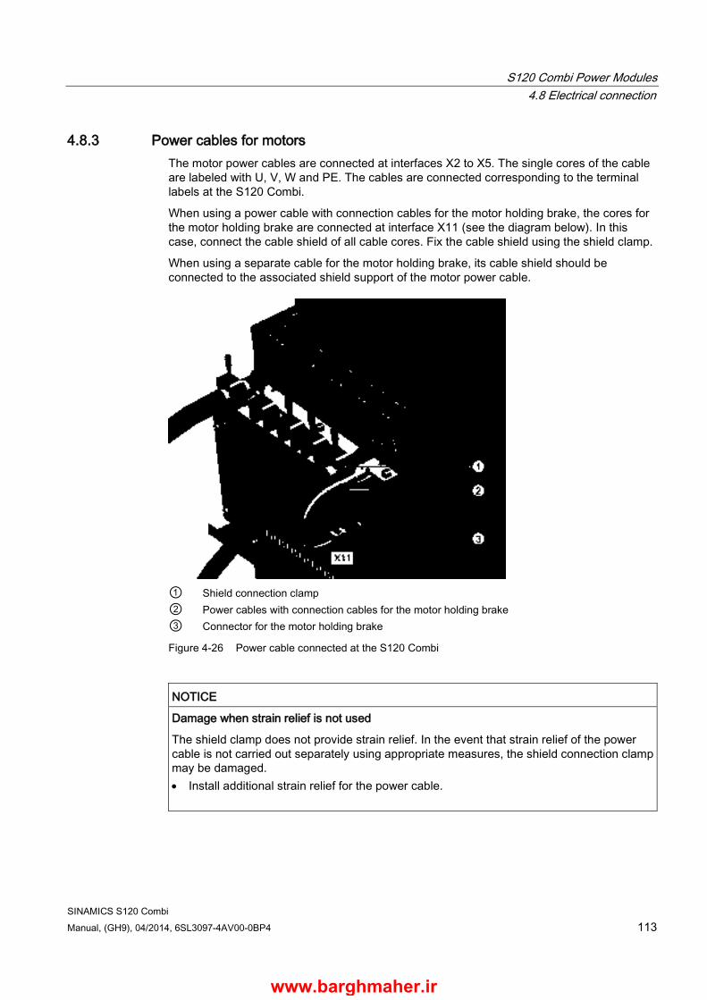
S120 Combi Power Modules 4.8 Electrical connection
SINAMICS S120 Combi Manual, (GH9), 04/2014, 6SL3097-4AV00-0BP4 113
4.8.3 Power cables for motors The motor power cables are connected at interfaces X2 to X5. The single cores of the cable are labeled with U, V, W and PE. The cables are connected corresponding to the terminal labels at the S120 Combi.
When using a power cable with connection cables for the motor holding brake, the cores for the motor holding brake are connected at interface X11 (see the diagram below). In this case, connect the cable shield of all cable cores. Fix the cable shield using the shield clamp.
When using a separate cable for the motor holding brake, its cable shield should be connected to the associated shield support of the motor power cable.
① Shield connection clamp ② Power cables with connection cables for the motor holding brake ③ Connector for the motor holding brake
Figure 4-26 Power cable connected at the S120 Combi
NOTICE
Damage when strain relief is not used
The shield clamp does not provide strain relief. In the event that strain relief of the power cable is not carried out separately using appropriate measures, the shield connection clamp may be damaged. • Install additional strain relief for the power cable.
www.barghmaher.ir

S120 Combi Power Modules 4.8 Electrical connection
SINAMICS S120 Combi 114 Manual, (GH9), 04/2014, 6SL3097-4AV00-0BP4
4.8.4 Signal cables at the EP terminals The shields of the signal cables connected to the EP terminals X21 and X22 are connected using the shield clamp ① from the accessories pack (Weidmüller: KLBÜ 4-13.5). The connection involves the following steps:
● Secure the shield connection clamp on the S120 Combi. Use an SW3 wrench with 1.8 Nm tightening torque.
● Remove the insulation from the signal cables and crimp the individual cores with end sleeves.
● Connect the cable cores to the EP terminals (screw terminals).
● Connect the cable shields as shown below.
Figure 4-27 Signal cables connected with the correct shield support
www.barghmaher.ir
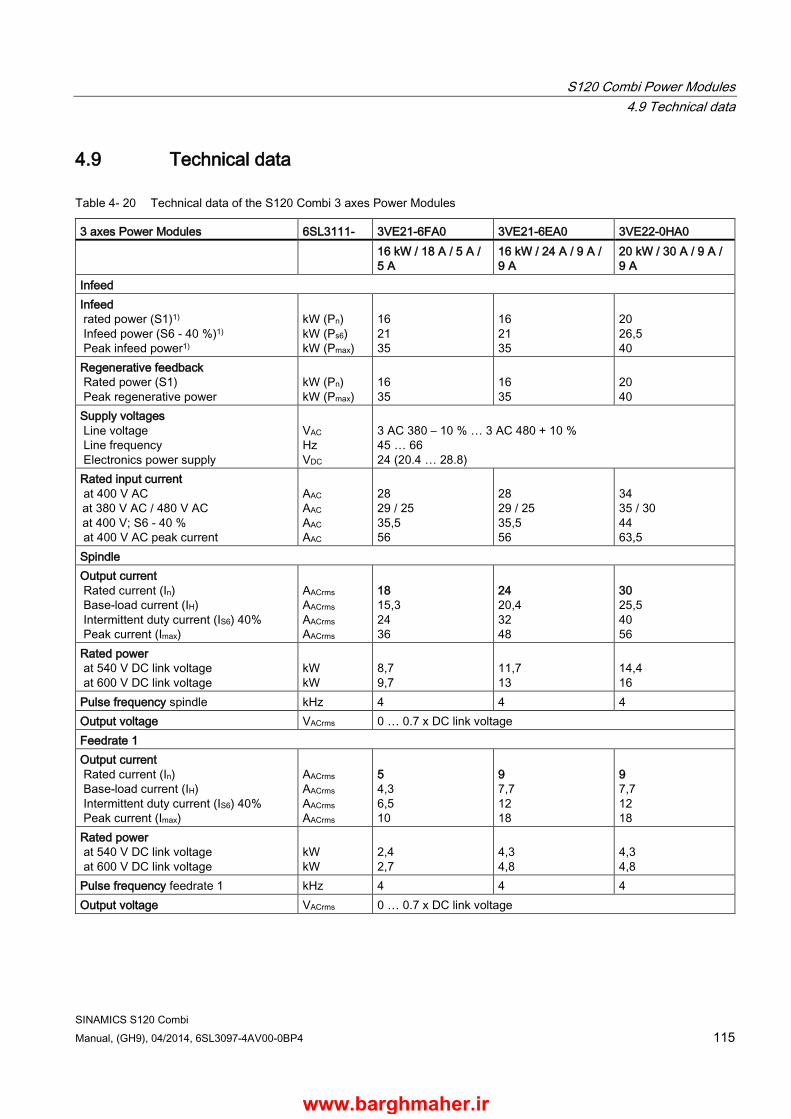
S120 Combi Power Modules 4.9 Technical data
SINAMICS S120 Combi Manual, (GH9), 04/2014, 6SL3097-4AV00-0BP4 115
4.9 Technical data
Table 4- 20 Technical data of the S120 Combi 3 axes Power Modules
3 axes Power Modules 6SL3111- 3VE21-6FA0 3VE21-6EA0 3VE22-0HA0 16 kW / 18 A / 5 A /
5 A 16 kW / 24 A / 9 A / 9 A
20 kW / 30 A / 9 A / 9 A
Infeed Infeed rated power (S1)1) Infeed power (S6 - 40 %)1) Peak infeed power1)
kW (Pn) kW (Ps6) kW (Pmax)
16 21 35
16 21 35
20 26,5 40
Regenerative feedback Rated power (S1) Peak regenerative power
kW (Pn) kW (Pmax)
16 35
16 35
20 40
Supply voltages Line voltage Line frequency Electronics power supply
VAC Hz VDC
3 AC 380 – 10 % … 3 AC 480 + 10 % 45 … 66 24 (20.4 … 28.8)
Rated input current at 400 V AC
at 380 V AC / 480 V AC
at 400 V; S6 - 40 % at 400 V AC peak current
AAC AAC AAC AAC
28 29 / 25 35,5 56
28 29 / 25 35,5 56
34 35 / 30 44 63,5
Spindle Output current Rated current (In) Base-load current (IH) Intermittent duty current (IS6) 40% Peak current (Imax)
AACrms AACrms AACrms AACrms
18 15,3 24 36
24 20,4 32 48
30 25,5 40 56
Rated power at 540 V DC link voltage at 600 V DC link voltage
kW kW
8,7 9,7
11,7 13
14,4 16
Pulse frequency spindle kHz 4 4 4 Output voltage VACrms 0 … 0.7 x DC link voltage Feedrate 1 Output current Rated current (In) Base-load current (IH) Intermittent duty current (IS6) 40% Peak current (Imax)
AACrms AACrms
AACrms AACrms
5 4,3 6,5 10
9 7,7 12 18
9 7,7 12 18
Rated power at 540 V DC link voltage at 600 V DC link voltage
kW kW
2,4 2,7
4,3 4,8
4,3 4,8
Pulse frequency feedrate 1 kHz 4 4 4 Output voltage VACrms 0 … 0.7 x DC link voltage
www.barghmaher.ir

S120 Combi Power Modules 4.9 Technical data
SINAMICS S120 Combi 116 Manual, (GH9), 04/2014, 6SL3097-4AV00-0BP4
3 axes Power Modules 6SL3111- 3VE21-6FA0 3VE21-6EA0 3VE22-0HA0 Feedrate 2 Output current Rated current (In) Base-load current (IH) Intermittent duty current (IS6) 40% Peak current (Imax)
AACrms AACrms AACrms AACrms
5 4,3 6,5 10
9 7,7 12 18
9 7,7 12 18
Rated power at 540 V DC link voltage at 600 V DC link voltage
kW kW
2,4 2,7
4,3 4,8
4,3 4,8
Pulse frequency feedrate 2 kHz 4 4 4 Output voltage VACrms 0 … 0.7 x DC link voltage Output for expansion axis DC link voltage VDC 460 … 720 DC link output current (In) ADC 40 Max. electronics output current for expansion axis
A24Vmax 20
General data Electronics current drawn at 24 V DC without external fan unit with external fan unit
A A
1,5 2,3
1,5 2,3
1,5 2,3
Total power loss (including losses from the electronics, see Power loss tables (Page 318)) internal external The external 6SL3161-0EP00-0AA0 fan module is taken into account for the specified losses – also see Power loss calculation for partial load operation (Page 321).
W W W
425 81 344
537 91 446
634 102 532
Max. ambient temperature Without derating With derating
°C °C
45 55
45 55
45 55
DC link voltage VDC 460 … 720 DC link capacitance μF 1645 1880 2115 Overvoltage tripping Undervoltage tripping
VDC VDC
820 ± 2 % 380 ± 2 %
Circuit breaker/fuse (IEC 60947 and UL)
See Chapter Overcurrent protection by means of line fuses and circuit breakers (Page 37)
Resulting rated short-circuit current SCCR at 480 V AC
kA
65
65
65
Cooling method External air cooling Cooling air requirement m3/h 160 160 160 Weight kg 18,35 18,4 18,5 1) The specified power ratings apply to the line voltage range from 380 V to 480 V
www.barghmaher.ir
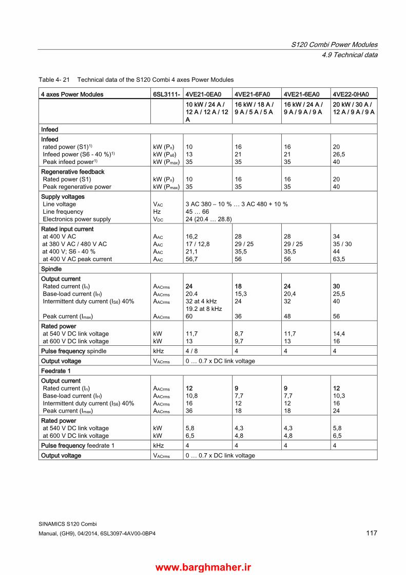
S120 Combi Power Modules 4.9 Technical data
SINAMICS S120 Combi Manual, (GH9), 04/2014, 6SL3097-4AV00-0BP4 117
Table 4- 21 Technical data of the S120 Combi 4 axes Power Modules
4 axes Power Modules 6SL3111- 4VE21-0EA0 4VE21-6FA0 4VE21-6EA0 4VE22-0HA0 10 kW / 24 A /
12 A / 12 A / 12 A
16 kW / 18 A / 9 A / 5 A / 5 A
16 kW / 24 A / 9 A / 9 A / 9 A
20 kW / 30 A / 12 A / 9 A / 9 A
Infeed Infeed rated power (S1)1) Infeed power (S6 - 40 %)1) Peak infeed power1)
kW (Pn) kW (Ps6) kW (Pmax)
10 13 35
16 21 35
16 21 35
20 26,5 40
Regenerative feedback Rated power (S1) Peak regenerative power
kW (Pn) kW (Pmax)
10 35
16 35
16 35
20 40
Supply voltages Line voltage Line frequency Electronics power supply
VAC Hz VDC
3 AC 380 – 10 % … 3 AC 480 + 10 % 45 … 66 24 (20.4 … 28.8)
Rated input current at 400 V AC
at 380 V AC / 480 V AC
at 400 V; S6 - 40 % at 400 V AC peak current
AAC AAC AAC AAC
16,2 17 / 12,8 21,1 56,7
28 29 / 25 35,5 56
28 29 / 25 35,5 56
34 35 / 30 44 63,5
Spindle Output current Rated current (In) Base-load current (IH) Intermittent duty current (IS6) 40% Peak current (Imax)
AACrms AACrms AACrms AACrms
24 20.4 32 at 4 kHz 19.2 at 8 kHz 60
18 15,3 24 36
24 20,4 32 48
30 25,5 40 56
Rated power at 540 V DC link voltage at 600 V DC link voltage
kW kW
11,7 13
8,7 9,7
11,7 13
14,4 16
Pulse frequency spindle kHz 4 / 8 4 4 4 Output voltage VACrms 0 … 0.7 x DC link voltage Feedrate 1 Output current Rated current (In) Base-load current (IH) Intermittent duty current (IS6) 40% Peak current (Imax)
AACrms AACrms AACrms AACrms
12 10,8 16 36
9 7,7 12 18
9 7,7 12 18
12 10,3 16 24
Rated power at 540 V DC link voltage at 600 V DC link voltage
kW kW
5,8 6,5
4,3 4,8
4,3 4,8
5,8 6,5
Pulse frequency feedrate 1 kHz 4 4 4 4 Output voltage VACrms 0 … 0.7 x DC link voltage
www.barghmaher.ir
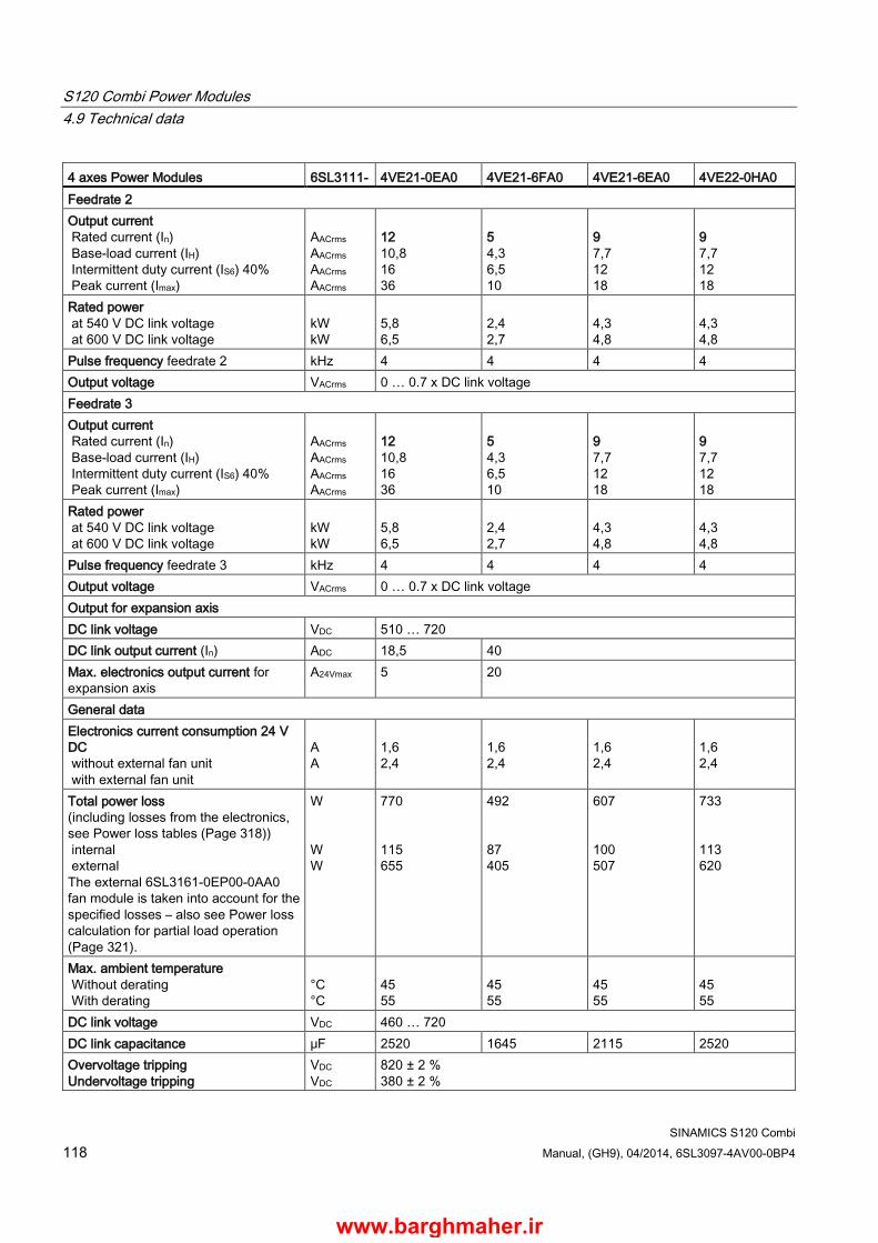
S120 Combi Power Modules 4.9 Technical data
SINAMICS S120 Combi 118 Manual, (GH9), 04/2014, 6SL3097-4AV00-0BP4
4 axes Power Modules 6SL3111- 4VE21-0EA0 4VE21-6FA0 4VE21-6EA0 4VE22-0HA0 Feedrate 2 Output current Rated current (In) Base-load current (IH) Intermittent duty current (IS6) 40% Peak current (Imax)
AACrms AACrms AACrms AACrms
12 10,8 16 36
5 4,3 6,5 10
9 7,7 12 18
9 7,7 12 18
Rated power at 540 V DC link voltage at 600 V DC link voltage
kW kW
5,8 6,5
2,4 2,7
4,3 4,8
4,3 4,8
Pulse frequency feedrate 2 kHz 4 4 4 4 Output voltage VACrms 0 … 0.7 x DC link voltage Feedrate 3 Output current Rated current (In) Base-load current (IH) Intermittent duty current (IS6) 40% Peak current (Imax)
AACrms AACrms AACrms AACrms
12 10,8 16 36
5 4,3 6,5 10
9 7,7 12 18
9 7,7 12 18
Rated power at 540 V DC link voltage at 600 V DC link voltage
kW kW
5,8 6,5
2,4 2,7
4,3 4,8
4,3 4,8
Pulse frequency feedrate 3 kHz 4 4 4 4 Output voltage VACrms 0 … 0.7 x DC link voltage Output for expansion axis DC link voltage VDC 510 … 720 DC link output current (In) ADC 18,5 40 Max. electronics output current for expansion axis
A24Vmax 5 20
General data Electronics current consumption 24 V DC without external fan unit with external fan unit
A A
1,6 2,4
1,6 2,4
1,6 2,4
1,6 2,4
Total power loss (including losses from the electronics, see Power loss tables (Page 318)) internal external The external 6SL3161-0EP00-0AA0 fan module is taken into account for the specified losses – also see Power loss calculation for partial load operation (Page 321).
W W W
770 115 655
492 87 405
607 100 507
733 113 620
Max. ambient temperature Without derating With derating
°C °C
45 55
45 55
45 55
45 55
DC link voltage VDC 460 … 720 DC link capacitance μF 2520 1645 2115 2520 Overvoltage tripping Undervoltage tripping
VDC VDC
820 ± 2 % 380 ± 2 %
www.barghmaher.ir

S120 Combi Power Modules 4.9 Technical data
SINAMICS S120 Combi Manual, (GH9), 04/2014, 6SL3097-4AV00-0BP4 119
4 axes Power Modules 6SL3111- 4VE21-0EA0 4VE21-6FA0 4VE21-6EA0 4VE22-0HA0 Circuit breaker/fuse (IEC 60947 and UL)
See Chapter Overcurrent protection by means of line fuses and circuit breakers (Page 37)
Resulting rated short-circuit current SCCR at 480 V AC
kA
65
65
65
65
Cooling method External air cooling Cooling air requirement m3/h 160 160 160 160 Weight kg 19,4 18,9 18,95 19,05 1) The specified power ratings apply to the line voltage range from 380 V to 480 V
www.barghmaher.ir

S120 Combi Power Modules 4.9 Technical data
SINAMICS S120 Combi 120 Manual, (GH9), 04/2014, 6SL3097-4AV00-0BP4
4.9.1 Characteristic curves The following rated duty cycles apply to the Power Modules:
● 6SL3111-3VE21-6FA0
● 6SL3111-3VE21-6EA0
● 6SL3111-3VE22-0HA0
● 6SL3111-4VE21-6FA0
● 6SL3111-4VE21-6EA0
● 6SL3111-4VE22-0HA0
Rated duty cycles, infeed
Figure 4-28 Rated duty cycles, infeed
www.barghmaher.ir
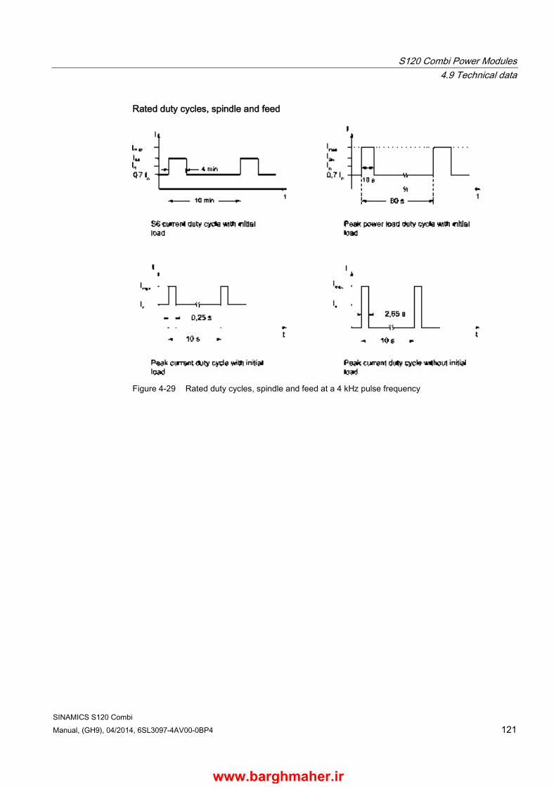
S120 Combi Power Modules 4.9 Technical data
SINAMICS S120 Combi Manual, (GH9), 04/2014, 6SL3097-4AV00-0BP4 121
Rated duty cycles, spindle and feed
Figure 4-29 Rated duty cycles, spindle and feed at a 4 kHz pulse frequency
www.barghmaher.ir
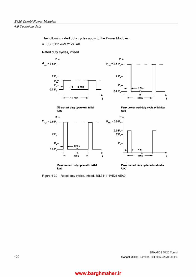
S120 Combi Power Modules 4.9 Technical data
SINAMICS S120 Combi 122 Manual, (GH9), 04/2014, 6SL3097-4AV00-0BP4
The following rated duty cycles apply to the Power Modules:
● 6SL3111-4VE21-0EA0
Rated duty cycles, infeed
Figure 4-30 Rated duty cycles, infeed, 6SL3111-4VE21-0EA0
www.barghmaher.ir

S120 Combi Power Modules 4.9 Technical data
SINAMICS S120 Combi Manual, (GH9), 04/2014, 6SL3097-4AV00-0BP4 123
Rated duty cycles, spindle
Figure 4-31 Rated duty cycles, spindle for a 4 kHz pulse frequency
www.barghmaher.ir
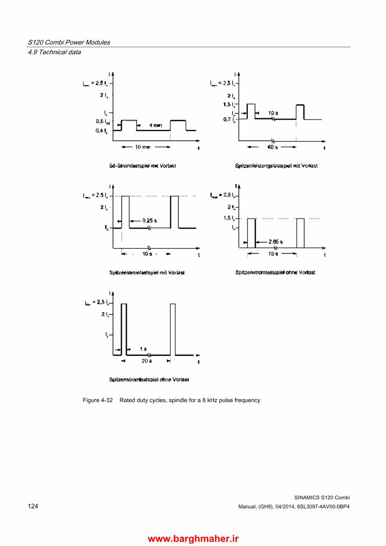
S120 Combi Power Modules 4.9 Technical data
SINAMICS S120 Combi 124 Manual, (GH9), 04/2014, 6SL3097-4AV00-0BP4
Figure 4-32 Rated duty cycles, spindle for a 8 kHz pulse frequency
www.barghmaher.ir

S120 Combi Power Modules 4.9 Technical data
SINAMICS S120 Combi Manual, (GH9), 04/2014, 6SL3097-4AV00-0BP4 125
Rated duty cycles, feed
Figure 4-33 Rated duty cycles, feed for a 4 kHz pulse frequency
www.barghmaher.ir
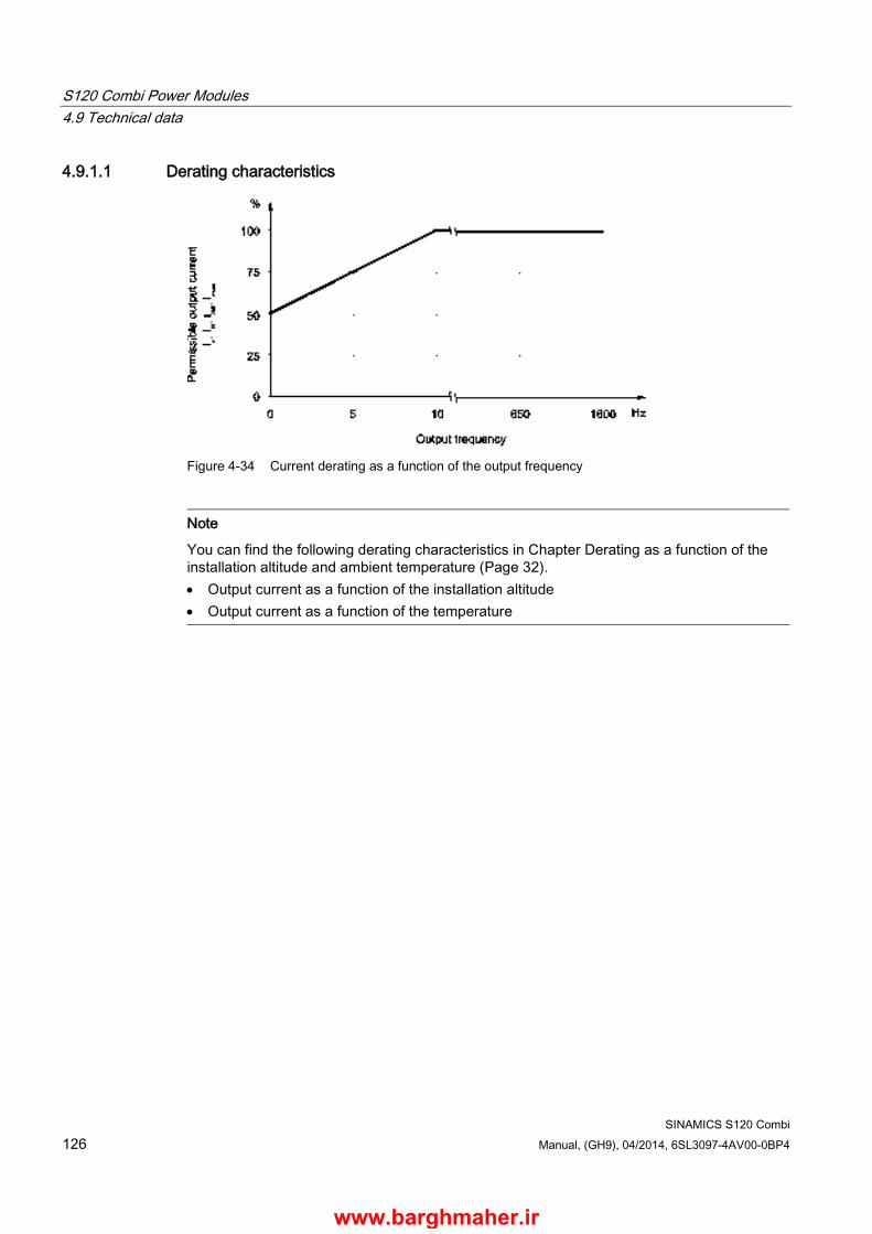
S120 Combi Power Modules 4.9 Technical data
SINAMICS S120 Combi 126 Manual, (GH9), 04/2014, 6SL3097-4AV00-0BP4
4.9.1.1 Derating characteristics
Figure 4-34 Current derating as a function of the output frequency
Note
You can find the following derating characteristics in Chapter Derating as a function of the installation altitude and ambient temperature (Page 32). • Output current as a function of the installation altitude • Output current as a function of the temperature
www.barghmaher.ir
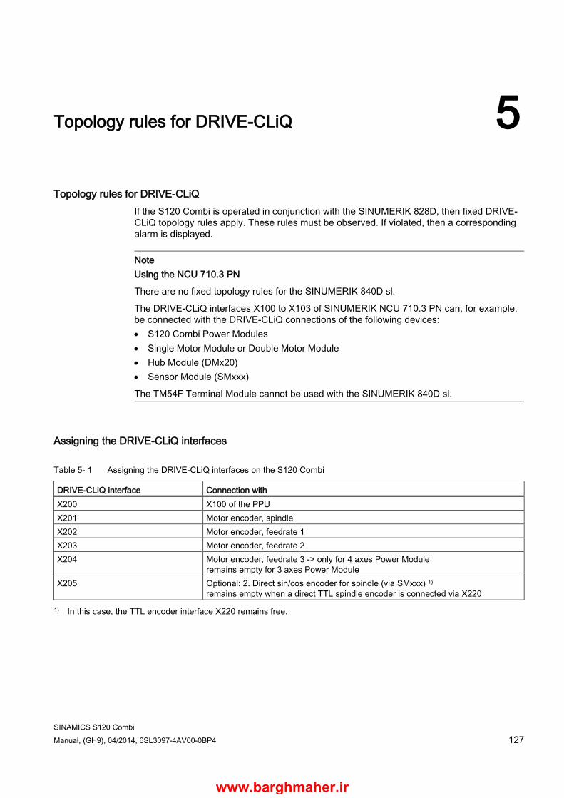
SINAMICS S120 Combi Manual, (GH9), 04/2014, 6SL3097-4AV00-0BP4 127
Topology rules for DRIVE-CLiQ 5
Topology rules for DRIVE-CLiQ If the S120 Combi is operated in conjunction with the SINUMERIK 828D, then fixed DRIVE-CLiQ topology rules apply. These rules must be observed. If violated, then a corresponding alarm is displayed.
Note Using the NCU 710.3 PN
There are no fixed topology rules for the SINUMERIK 840D sl.
The DRIVE-CLiQ interfaces X100 to X103 of SINUMERIK NCU 710.3 PN can, for example, be connected with the DRIVE-CLiQ connections of the following devices: • S120 Combi Power Modules • Single Motor Module or Double Motor Module • Hub Module (DMx20) • Sensor Module (SMxxx)
The TM54F Terminal Module cannot be used with the SINUMERIK 840D sl.
Assigning the DRIVE-CLiQ interfaces
Table 5- 1 Assigning the DRIVE-CLiQ interfaces on the S120 Combi
DRIVE-CLiQ interface Connection with X200 X100 of the PPU X201 Motor encoder, spindle X202 Motor encoder, feedrate 1 X203 Motor encoder, feedrate 2 X204 Motor encoder, feedrate 3 -> only for 4 axes Power Module
remains empty for 3 axes Power Module X205 Optional: 2. Direct sin/cos encoder for spindle (via SMxxx) 1)
remains empty when a direct TTL spindle encoder is connected via X220 1) In this case, the TTL encoder interface X220 remains free.
www.barghmaher.ir

Topology rules for DRIVE-CLiQ
SINAMICS S120 Combi 128 Manual, (GH9), 04/2014, 6SL3097-4AV00-0BP4
Table 5- 2 Assigning the DRIVE-CLiQ interfaces to the SINUMERIK 828D (PPU)
DRIVE-CLiQ interface Connection with X100 X200 of the S120 Combi X101 X200 of a Single Motor Module or Double Motor Module X102 X500 of the Terminal Module TM54F
X500 of the Hub Module (DMx20)1) 1) When using a TM54F, the DMx20 is connected in series at the TM54F via the DRIVE-CLiQ interface X501
Table 5- 3 Assigning the DRIVE-CLiQ interfaces of the expansion axes
DRIVE-CLiQ interface Connection with First Single Motor Module X200 X101 of the PPU X2011) X200 of the second Single Motor Module X202 Motor encoder for feedrate 1st expansion axis (via Sensor Module) Second Single Motor Module X200 X201 of the first Single Motor Module X201 Remains empty X202 Motor encoder for feedrate 2nd expansion axis (via Sensor Module) Double Motor Module X200 X101 of the PPU X201 Remains empty X202 Motor encoder for feedrate 1st expansion axis X203 Motor encoder for feedrate 2nd expansion axis 1) Remains empty if only one Single Motor Module is used
Table 5- 4 Assigning the DRIVE-CLiQ interfaces at the TM54F
DRIVE-CLiQ interface X500 X102 of the control (PPU) X501 X500 of the DMx20
if a DMx20 is not used, then this interface remains empty
www.barghmaher.ir

Topology rules for DRIVE-CLiQ
SINAMICS S120 Combi Manual, (GH9), 04/2014, 6SL3097-4AV00-0BP4 129
Table 5- 5 Assigning the DRIVE-CLiQ interfaces at the DMx20 to assign a direct measuring system to the feed axes.
DRIVE-CLiQ interface Feed axis X500 X501 of the TM54F
X102 of the PPU1)
X100 … X103 of the NCU X501 Feedrate 1 at the S120 Combi X502 Feedrate 2 at the S120 Combi X503 Feedrate 3 at the S120 Combi (4 axes Power Modules) X504 Feedrate 1st expansion axis at the Motor Module X505 Feedrate 2nd expansion axis at the Motor Module 1) Only then, if a TM54F is not used
www.barghmaher.ir
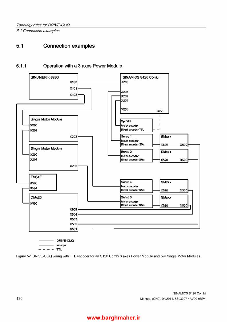
Topology rules for DRIVE-CLiQ 5.1 Connection examples
SINAMICS S120 Combi 130 Manual, (GH9), 04/2014, 6SL3097-4AV00-0BP4
5.1 Connection examples
5.1.1 Operation with a 3 axes Power Module
Figure 5-1 DRIVE-CLiQ wiring with TTL encoder for an S120 Combi 3 axes Power Module and two Single Motor Modules
www.barghmaher.ir
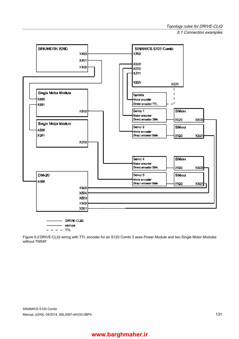
Topology rules for DRIVE-CLiQ 5.1 Connection examples
SINAMICS S120 Combi Manual, (GH9), 04/2014, 6SL3097-4AV00-0BP4 131
Figure 5-2 DRIVE-CLiQ wiring with TTL encoder for an S120 Combi 3 axes Power Module and two Single Motor Modules without TM54F
www.barghmaher.ir
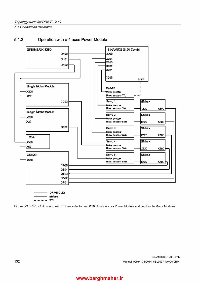
Topology rules for DRIVE-CLiQ 5.1 Connection examples
SINAMICS S120 Combi 132 Manual, (GH9), 04/2014, 6SL3097-4AV00-0BP4
5.1.2 Operation with a 4 axes Power Module
Figure 5-3 DRIVE-CLiQ wiring with TTL encoder for an S120 Combi 4 axes Power Module and two Single Motor Modules
www.barghmaher.ir
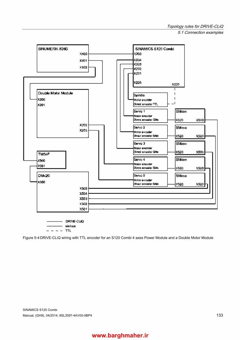
Topology rules for DRIVE-CLiQ 5.1 Connection examples
SINAMICS S120 Combi Manual, (GH9), 04/2014, 6SL3097-4AV00-0BP4 133
Figure 5-4 DRIVE-CLiQ wiring with TTL encoder for an S120 Combi 4 axes Power Module and a Double Motor Module
www.barghmaher.ir

Topology rules for DRIVE-CLiQ 5.1 Connection examples
SINAMICS S120 Combi 134 Manual, (GH9), 04/2014, 6SL3097-4AV00-0BP4
Figure 5-5 DRIVE-CLiQ wiring with angular encoder for an S120 Combi 4 axes Power Module and two Single Motor Modules
www.barghmaher.ir
SINAMICS S120 Combi Manual, (GH9), 04/2014, 6SL3097-4AV00-0BP4 135
Motor Modules Booksize Compact as expansion axes 6 6.1 Description
Motor Modules Booksize Compact are inverters that provide the power for the connected motors. The power is supplied from the DC link of the S120 Combi. If the SINUMERIK 828D control system is used, then the Motor Modules must be connected to this via DRIVE-CLiQ (see Chapter Topology rules for DRIVE-CLiQ (Page 127)).
One motor can be connected to Single Motor Modules and two motors can be connected to Double Motor Modules.
The Motor Modules Booksize Compact are operated in combination with the S120 Combi using the "internal air cooling" cooling method.
Note
For the dimensioning of the expansion axes, the infeed power must be taken into account (demand factor).
www.barghmaher.ir
Motor Modules Booksize Compact as expansion axes 6.2 Safety information
SINAMICS S120 Combi 136 Manual, (GH9), 04/2014, 6SL3097-4AV00-0BP4
6.2 Safety information
WARNING
Danger to life if the fundamental safety instructions and remaining risks are not carefully observed
If the fundamental safety instructions and remaining risks in Chapter 1 (Page 312) are not observed, accidents involving severe injuries or death may occur. • Adhere to the fundamental safety instructions. • When assessing the risk, take into account residual risks.
DANGER
Danger to life through electric shock due to the residual charge of the DC link capacitors
Due to the DC link capacitors, a hazardous voltage is present in the DC link for up to five minutes after the power supply has been switched off.
Contact with live parts can result in death or serious injury. • Do not open the protective cover of the DC link until five minutes have elapsed.
Ensure that you press the release catch when opening the protective cover for the DC link. A suitable tool (e.g. screwdriver or supplied release tool) must be used for this purpose.
• Do not continue to operate damaged components.
DANGER
Danger to life through electric shock due to inadequate insulation of the motor holding brake cables
Inadequate insulation of the motor holding brake cables can cause an electric shock. • Connect the shield for the motor holding brake. • Only use MOTION-CONNECT cables for the integrated motor holding brake, as
otherwise the insulation strength of the cores is not guaranteed.
WARNING
Danger of an accident due to missing warning labels in the national language regarding the DC link discharge voltage
Missing warning labels in the national language regarding the DC link discharge voltage can result in death or serious injury. • Attach the component warning labels in the national language.
www.barghmaher.ir
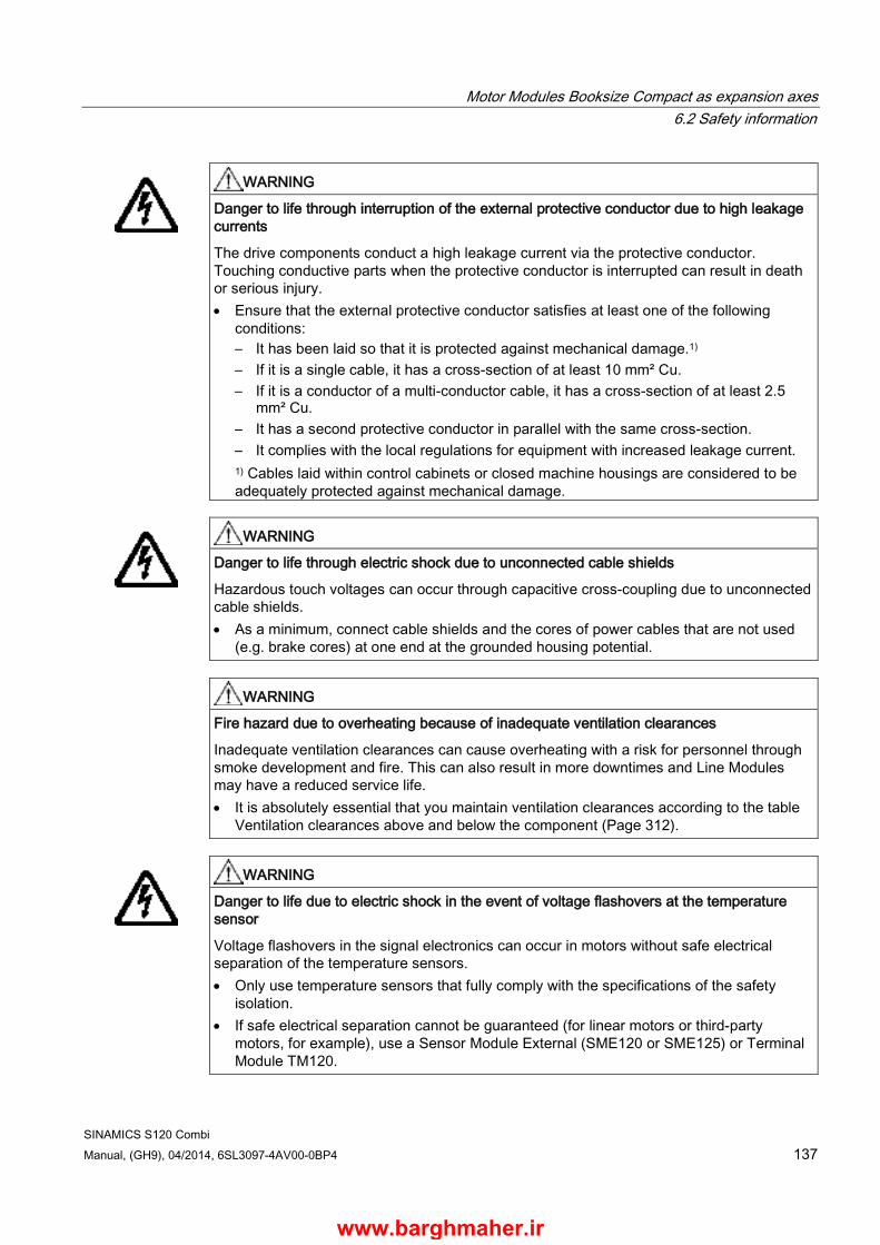
Motor Modules Booksize Compact as expansion axes 6.2 Safety information
SINAMICS S120 Combi Manual, (GH9), 04/2014, 6SL3097-4AV00-0BP4 137
WARNING
Danger to life through interruption of the external protective conductor due to high leakage currents
The drive components conduct a high leakage current via the protective conductor. Touching conductive parts when the protective conductor is interrupted can result in death or serious injury. • Ensure that the external protective conductor satisfies at least one of the following
conditions: – It has been laid so that it is protected against mechanical damage.1) – If it is a single cable, it has a cross-section of at least 10 mm² Cu. – If it is a conductor of a multi-conductor cable, it has a cross-section of at least 2.5
mm² Cu. – It has a second protective conductor in parallel with the same cross-section. – It complies with the local regulations for equipment with increased leakage current. 1) Cables laid within control cabinets or closed machine housings are considered to be adequately protected against mechanical damage.
WARNING
Danger to life through electric shock due to unconnected cable shields
Hazardous touch voltages can occur through capacitive cross-coupling due to unconnected cable shields. • As a minimum, connect cable shields and the cores of power cables that are not used
(e.g. brake cores) at one end at the grounded housing potential.
WARNING
Fire hazard due to overheating because of inadequate ventilation clearances
Inadequate ventilation clearances can cause overheating with a risk for personnel through smoke development and fire. This can also result in more downtimes and Line Modules may have a reduced service life. • It is absolutely essential that you maintain ventilation clearances according to the table
Ventilation clearances above and below the component (Page 312).
WARNING
Danger to life due to electric shock in the event of voltage flashovers at the temperature sensor
Voltage flashovers in the signal electronics can occur in motors without safe electrical separation of the temperature sensors. • Only use temperature sensors that fully comply with the specifications of the safety
isolation. • If safe electrical separation cannot be guaranteed (for linear motors or third-party
motors, for example), use a Sensor Module External (SME120 or SME125) or Terminal Module TM120.
www.barghmaher.ir
Motor Modules Booksize Compact as expansion axes 6.2 Safety information
SINAMICS S120 Combi 138 Manual, (GH9), 04/2014, 6SL3097-4AV00-0BP4
WARNING
Danger to life through electric shock due to missing DC link side covers
There is a danger of an electric shock through contact when the side covers of the DC link are missing. • Mount the supplied side covers on the first and last component in the drive line-up. • You can order missing side covers (order number: 6SL3162-5AA00-0AA0).
NOTICE
Material damage due to loose power connections
Insufficient tightening torques or vibrations can result in faulty electrical connections. This can cause fire damage or malfunctions. • Tighten all the DC link busbar screws with the specified tightening torques (1.8 Nm
tolerance +30 %). • Check the tightening torques of all power connections at regular intervals and tighten
them when required. This applies in particular after transport.
NOTICE
Damage through use of incorrect DRIVE-CLiQ cables
Damage or malfunctions can occur on the devices or system when incorrect or unreleased DRIVE-CLiQ cables are used. • Only use suitable DRIVE-CLiQ cables that have been released by Siemens for the
respective application.
Note
A regulated DC power supply is required to operate motors with a built-in holding brake. The voltage is supplied via the internal 24 V busbars. The voltage tolerances of the motor holding brakes (24 V ±10%) and the voltage drops of the connecting cables must be taken into account.
The DC power supply should be set to 26 V. This ensures that the supply voltage for the brake remains within the permissible range when the following conditions are fulfilled: • Use of Siemens three-phase motors • Use of Siemens MOTION-CONNECT power cables • Motor cable lengths: max. 70 m
www.barghmaher.ir
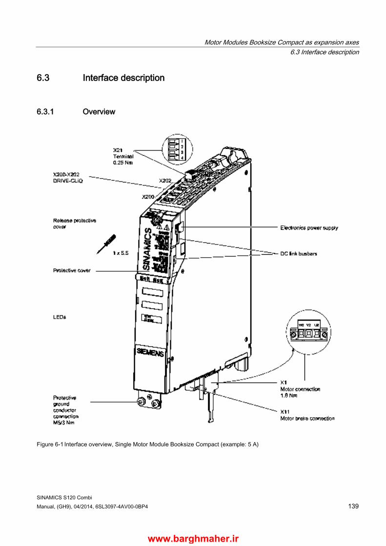
Motor Modules Booksize Compact as expansion axes 6.3 Interface description
SINAMICS S120 Combi Manual, (GH9), 04/2014, 6SL3097-4AV00-0BP4 139
6.3 Interface description
6.3.1 Overview
Figure 6-1 Interface overview, Single Motor Module Booksize Compact (example: 5 A)
www.barghmaher.ir
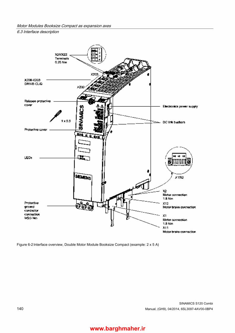
Motor Modules Booksize Compact as expansion axes 6.3 Interface description
SINAMICS S120 Combi 140 Manual, (GH9), 04/2014, 6SL3097-4AV00-0BP4
Figure 6-2 Interface overview, Double Motor Module Booksize Compact (example: 2 x 5 A)
www.barghmaher.ir
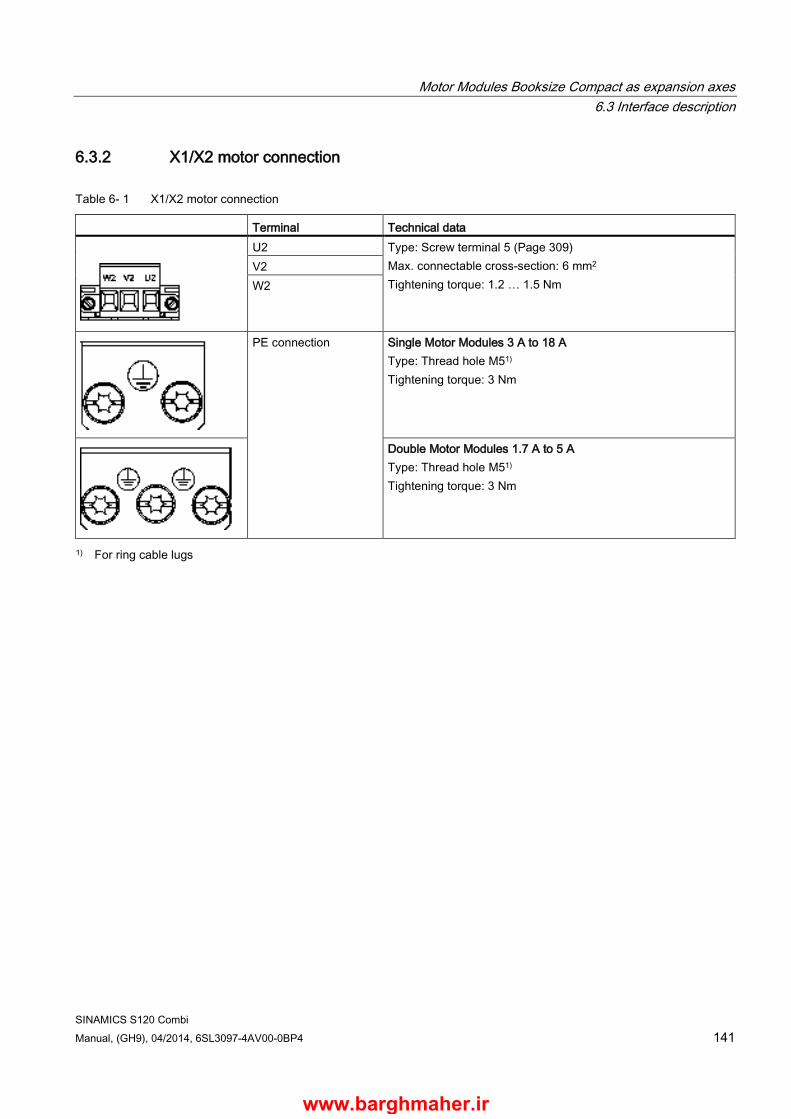
Motor Modules Booksize Compact as expansion axes 6.3 Interface description
SINAMICS S120 Combi Manual, (GH9), 04/2014, 6SL3097-4AV00-0BP4 141
6.3.2 X1/X2 motor connection
Table 6- 1 X1/X2 motor connection
Terminal Technical data
U2 Type: Screw terminal 5 (Page 309) Max. connectable cross-section: 6 mm2 Tightening torque: 1.2 … 1.5 Nm
V2 W2
PE connection Single Motor Modules 3 A to 18 A Type: Thread hole M51) Tightening torque: 3 Nm
Double Motor Modules 1.7 A to 5 A Type: Thread hole M51) Tightening torque: 3 Nm
1) For ring cable lugs
www.barghmaher.ir

Motor Modules Booksize Compact as expansion axes 6.3 Interface description
SINAMICS S120 Combi 142 Manual, (GH9), 04/2014, 6SL3097-4AV00-0BP4
6.3.3 X11/X12 motor brake connection
Table 6- 2 X11/X12 brake connection
Terminals Designation Technical data
BR+ Brake connection + Voltage: 24 V DC Max. load current: 2 A Minimum load current: 0.1 A Type: Spring-loaded terminal 1 (Page 308) Max. cross-section that can be connected: 2.5 mm2
Manufacturer: Wago Order number: 721-102/026-000/56-000
BR- Brake connection -
The brake connector is included in the scope of delivery.
The circuit for protecting the brake against overvoltage is integrated in the Motor Module and does not need to be installed externally.
Note
The motor brake must be connected via connector X11 on Single Motor Modules, and X11 and X12 on Double Motor Modules. The BR- cable must not be connected directly to electronics ground (M). The shield of the brake cable is only to be connected to the shield plate.
WARNING
Danger to life through electric shock due to a terminal voltage that has not been adjusted
Contact with live parts can result in death or serious injury. • Connect protective extra-low voltages (PELV) to all connections and terminals between
0 and 48 V DC. • Observe the voltage tolerances of the motor holding brakes (24 V ± 10%).
www.barghmaher.ir
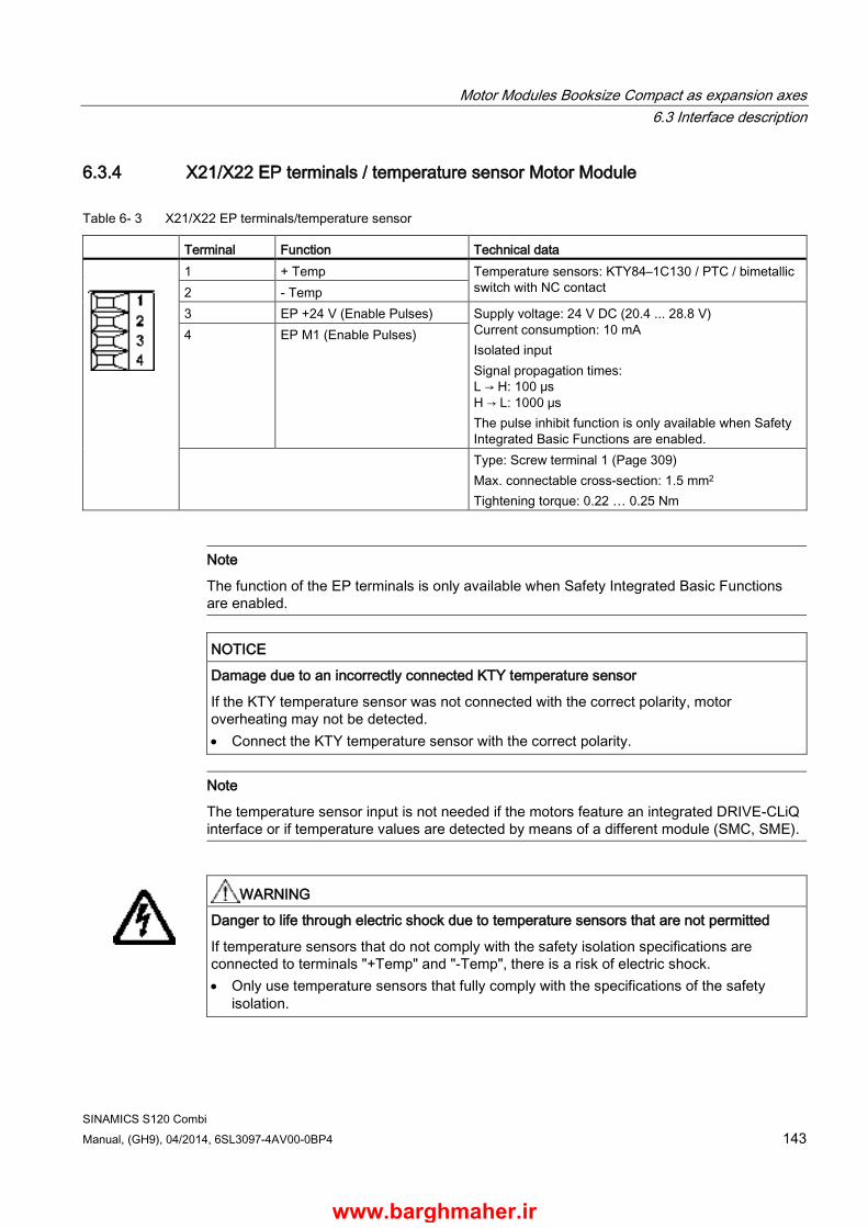
Motor Modules Booksize Compact as expansion axes 6.3 Interface description
SINAMICS S120 Combi Manual, (GH9), 04/2014, 6SL3097-4AV00-0BP4 143
6.3.4 X21/X22 EP terminals / temperature sensor Motor Module
Table 6- 3 X21/X22 EP terminals/temperature sensor
Terminal Function Technical data
1 + Temp Temperature sensors: KTY84–1C130 / PTC / bimetallic switch with NC contact 2 - Temp
3 EP +24 V (Enable Pulses) Supply voltage: 24 V DC (20.4 ... 28.8 V) Current consumption: 10 mA Isolated input Signal propagation times: L → H: 100 μs H → L: 1000 μs The pulse inhibit function is only available when Safety Integrated Basic Functions are enabled.
4 EP M1 (Enable Pulses)
Type: Screw terminal 1 (Page 309) Max. connectable cross-section: 1.5 mm2 Tightening torque: 0.22 … 0.25 Nm
Note
The function of the EP terminals is only available when Safety Integrated Basic Functions are enabled.
NOTICE
Damage due to an incorrectly connected KTY temperature sensor
If the KTY temperature sensor was not connected with the correct polarity, motor overheating may not be detected. • Connect the KTY temperature sensor with the correct polarity.
Note
The temperature sensor input is not needed if the motors feature an integrated DRIVE-CLiQ interface or if temperature values are detected by means of a different module (SMC, SME).
WARNING
Danger to life through electric shock due to temperature sensors that are not permitted
If temperature sensors that do not comply with the safety isolation specifications are connected to terminals "+Temp" and "-Temp", there is a risk of electric shock. • Only use temperature sensors that fully comply with the specifications of the safety
isolation.
www.barghmaher.ir
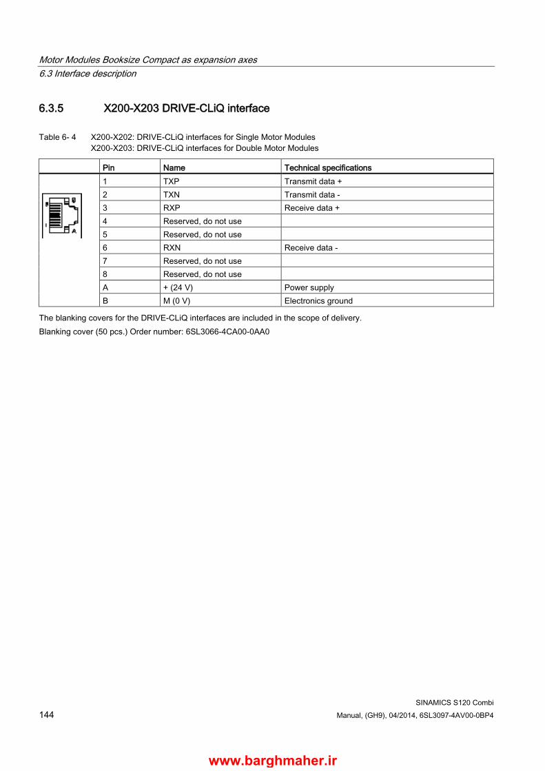
Motor Modules Booksize Compact as expansion axes 6.3 Interface description
SINAMICS S120 Combi 144 Manual, (GH9), 04/2014, 6SL3097-4AV00-0BP4
6.3.5 X200-X203 DRIVE-CLiQ interface
Table 6- 4 X200-X202: DRIVE-CLiQ interfaces for Single Motor Modules X200-X203: DRIVE-CLiQ interfaces for Double Motor Modules
Pin Name Technical specifications
1 TXP Transmit data + 2 TXN Transmit data - 3 RXP Receive data + 4 Reserved, do not use 5 Reserved, do not use 6 RXN Receive data - 7 Reserved, do not use 8 Reserved, do not use A + (24 V) Power supply B M (0 V) Electronics ground
The blanking covers for the DRIVE-CLiQ interfaces are included in the scope of delivery. Blanking cover (50 pcs.) Order number: 6SL3066-4CA00-0AA0
www.barghmaher.ir

Motor Modules Booksize Compact as expansion axes 6.4 Connection example
SINAMICS S120 Combi Manual, (GH9), 04/2014, 6SL3097-4AV00-0BP4 145
6.4 Connection example
Figure 6-3 Connection example, Single Motor Modules Booksize Compact 3 A to 18 A and Double Motor Modules Booksize Compact 1.7 A to 5 A
www.barghmaher.ir

Motor Modules Booksize Compact as expansion axes 6.5 Meaning of the LEDs on the Motor Module Booksize Compact
SINAMICS S120 Combi 146 Manual, (GH9), 04/2014, 6SL3097-4AV00-0BP4
6.5 Meaning of the LEDs on the Motor Module Booksize Compact
Table 6- 5 Meaning of the LEDs on the Single Motor Module/Double Motor Module
Status Description, cause Remedy RDY DC LINK OFF OFF The electronics power supply is missing or outside the
permissible tolerance range. –
Green -- The component is ready for operation. Cyclic DRIVE-CLiQ communication is taking place.
–
Orange The component is ready for operation. Cyclic DRIVE-CLiQ communication is taking place. The DC link voltage is present.
–
Red The component is ready for operation. Cyclic DRIVE-CLiQ communication is taking place. The DC link voltage is too high.
Check the line supply voltage.
Orange Orange DRIVE-CLiQ communication is being established. – Red -- This component has at least one fault.
Note: The LED is activated regardless of whether the corresponding messages have been reconfigured.
Remedy and acknowledge fault
Green / Red (0.5 Hz)
-- Firmware is being downloaded. –
Green / Red (2 Hz)
-- Firmware download is complete. Wait for POWER ON. Carry out a POWER ON
Green / Orange or Red / Orange
-- Component recognition via LED is activated. This function can be parameterized (see SINAMICS S120/S150 List Manual). Note: Both possibilities depend on the status of the LED when activating.
–
WARNING
Danger to life through electric shock due to applied DC link voltage
Irrespective of the state of the LED "DC LINK", hazardous DC-link voltages can always be present.
Death or serious injury can result when live parts are touched. • Observe the warning information on the component.
www.barghmaher.ir

Motor Modules Booksize Compact as expansion axes 6.6 Dimension drawings
SINAMICS S120 Combi Manual, (GH9), 04/2014, 6SL3097-4AV00-0BP4 147
6.6 Dimension drawings
Figure 6-4 Dimension drawing of 3 A, 5 A, and 9 A Motor Modules Booksize Compact, all dimensions in mm and (inches); example: 5 A Single Motor Module
Table 6- 6 Motor Modules Booksize Compact 3 A, 5 A, and 9 A
Motor Module Order number Single Motor Module 3 A 6SL3420-1TE13-0AAx Single Motor Module 5 A 6SL3420-1TE15-0AAx Single Motor Module 9 A 6SL3420-1TE21-0AAx
www.barghmaher.ir

Motor Modules Booksize Compact as expansion axes 6.6 Dimension drawings
SINAMICS S120 Combi 148 Manual, (GH9), 04/2014, 6SL3097-4AV00-0BP4
Figure 6-5 Dimension drawing of 18 A Motor Module Booksize Compact, all dimensions in mm and (inches)
Table 6- 7 Motor Module Booksize Compact 18 A
Motor Module Order number Single Motor Module 18 A 6SL3420-1TE21-8AAx
www.barghmaher.ir
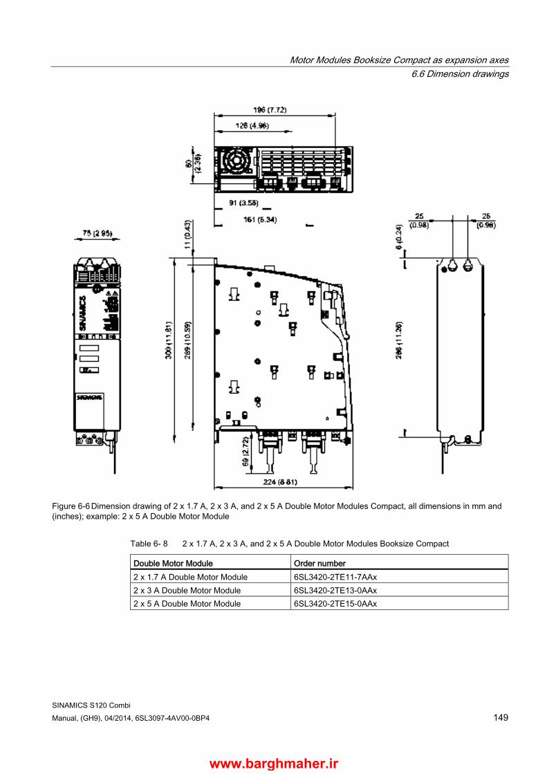
Motor Modules Booksize Compact as expansion axes 6.6 Dimension drawings
SINAMICS S120 Combi Manual, (GH9), 04/2014, 6SL3097-4AV00-0BP4 149
Figure 6-6 Dimension drawing of 2 x 1.7 A, 2 x 3 A, and 2 x 5 A Double Motor Modules Compact, all dimensions in mm and (inches); example: 2 x 5 A Double Motor Module
Table 6- 8 2 x 1.7 A, 2 x 3 A, and 2 x 5 A Double Motor Modules Booksize Compact
Double Motor Module Order number 2 x 1.7 A Double Motor Module 6SL3420-2TE11-7AAx 2 x 3 A Double Motor Module 6SL3420-2TE13-0AAx 2 x 5 A Double Motor Module 6SL3420-2TE15-0AAx
www.barghmaher.ir

Motor Modules Booksize Compact as expansion axes 6.7 Installation
SINAMICS S120 Combi 150 Manual, (GH9), 04/2014, 6SL3097-4AV00-0BP4
6.7 Installation
Installing a Motor Module Booksize Compact
① Mounting wall ② M6 x 16 screw
Hex combination screw or hex screw with spring washer and plain washer
Figure 6-7 Installing a Motor Module Booksize Compact with internal air cooling
Tightening torques:
● Initially, tighten by hand (0.5 Nm)
● Then tighten with 6 Nm (in the specific sequence 1 to 4)
www.barghmaher.ir

Motor Modules Booksize Compact as expansion axes 6.8 Technical data
SINAMICS S120 Combi Manual, (GH9), 04/2014, 6SL3097-4AV00-0BP4 151
6.8 Technical data
Table 6- 9 Technical data Single Motor Modules Booksize Compact (3 A to 18 A)
Single Motor Modules Booksize Compact 6SL3420– 1TE13-0AAx 1TE15-0AAx 1TE21–0AAx 1TE21–8AAx Output current Rated current (In) Base-load current (IH) Intermittent duty current (Is6) 40% Peak current (Imax)
AACrms A AACrms AACrms
3 2,6 3,5 9
5 4,3 6 15
9 7,7 10 27
18 15,3 24 54
Output voltage VACrms 0 … 0.717 x DC link voltage DC link current Id max ADC 3,6 6 11 22 DC link voltage (up to 2000 m above sea level)
VDC 510 … 720
DC link capacitance μF 110 110 110 235 Overvoltage tripping Undervoltage tripping1)
VDC VDC
820 ± 2 % 380 ± 2 %
Electronics power supply VDC 24 (20,4 … 28,8) Electronics current drawn at 24 V DC ADC 0,85 0,85 0,85 0,85 Current carrying capacity DC link busbar Reinforced DC link busbars 24 V busbar
ADC ADC ADC
100 150 20
100 150 20
100 150 20
100 150 20
Max. current motor brake A 2 2 2 2 Unit rating2) Based on In (600 V DC; 4 kHz) Based on IH
kW kW
1,6 1,4
2,7 2,3
4,8 4,1
9,7 13,7
Total power loss (including electronics losses)
(see Power loss tables (Page 318))
W 68 at 8 kHz
98 at 8 kHz
100,4 at 4 kHz
185,4 at 4 kHz
Max. pulse frequency Without derating With derating
kHz kHz
8 16
8 16
4 16
4 16
Max. ambient temperature Without derating With derating
°C °C
40 55
Sound pressure level dB(A) < 60 < 60 < 60 < 60 Cooling method Internal air
cooling
Cooling air requirement m3/h 29,6 29,6 29,6 29,6 Weight kg 2,7 2,7 2,7 3,4 1) Default setting for 400 V line supplies, undervoltage trip threshold can be reduced by up to 80 V and is adjusted to the
parameterized line voltage 2) Rated power of a typical standard induction motor at 400 V 3 AC.
www.barghmaher.ir
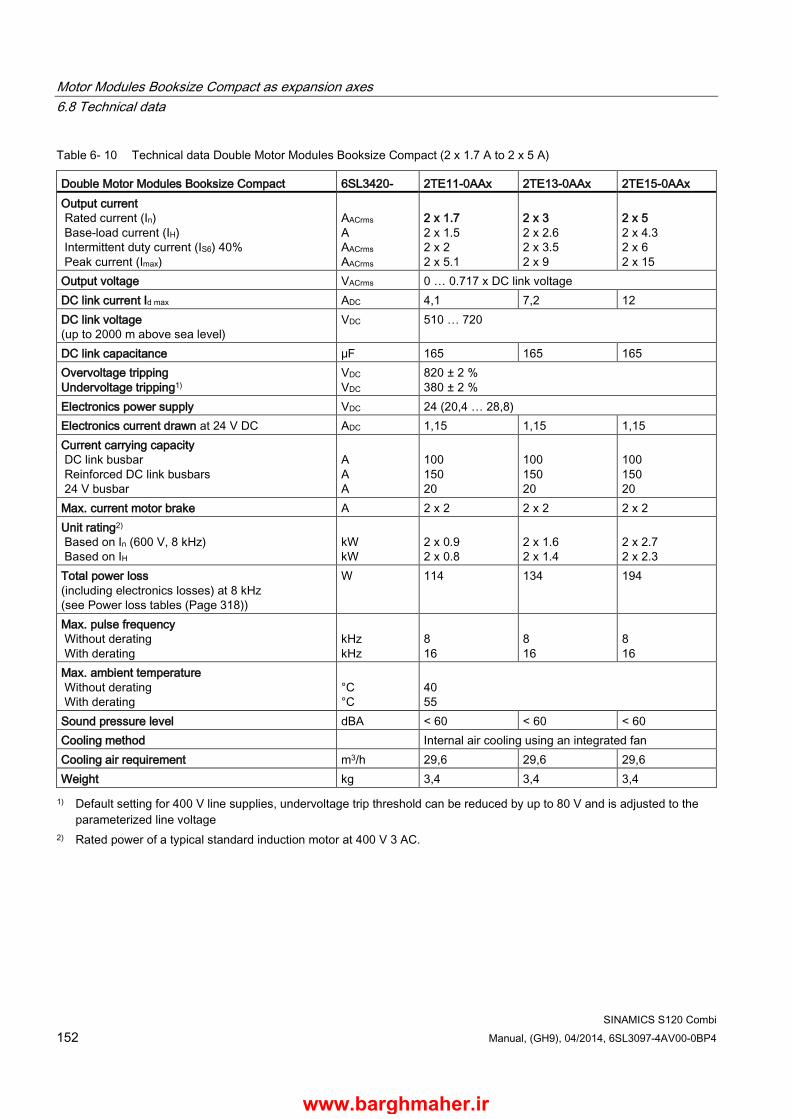
Motor Modules Booksize Compact as expansion axes 6.8 Technical data
SINAMICS S120 Combi 152 Manual, (GH9), 04/2014, 6SL3097-4AV00-0BP4
Table 6- 10 Technical data Double Motor Modules Booksize Compact (2 x 1.7 A to 2 x 5 A)
Double Motor Modules Booksize Compact 6SL3420- 2TE11-0AAx 2TE13-0AAx 2TE15-0AAx Output current Rated current (In) Base-load current (IH) Intermittent duty current (IS6) 40% Peak current (Imax)
AACrms A AACrms AACrms
2 x 1.7 2 x 1.5 2 x 2 2 x 5.1
2 x 3 2 x 2.6 2 x 3.5 2 x 9
2 x 5 2 x 4.3 2 x 6 2 x 15
Output voltage VACrms 0 … 0.717 x DC link voltage DC link current Id max ADC 4,1 7,2 12 DC link voltage (up to 2000 m above sea level)
VDC 510 … 720
DC link capacitance μF 165 165 165 Overvoltage tripping Undervoltage tripping1)
VDC VDC
820 ± 2 % 380 ± 2 %
Electronics power supply VDC 24 (20,4 … 28,8) Electronics current drawn at 24 V DC ADC 1,15 1,15 1,15 Current carrying capacity DC link busbar Reinforced DC link busbars 24 V busbar
A A A
100 150 20
100 150 20
100 150 20
Max. current motor brake A 2 x 2 2 x 2 2 x 2 Unit rating2) Based on In (600 V, 8 kHz) Based on IH
kW kW
2 x 0.9 2 x 0.8
2 x 1.6 2 x 1.4
2 x 2.7 2 x 2.3
Total power loss (including electronics losses) at 8 kHz (see Power loss tables (Page 318))
W 114 134 194
Max. pulse frequency Without derating With derating
kHz kHz
8 16
8 16
8 16
Max. ambient temperature Without derating With derating
°C °C
40 55
Sound pressure level dBA < 60 < 60 < 60 Cooling method Internal air cooling using an integrated fan Cooling air requirement m3/h 29,6 29,6 29,6 Weight kg 3,4 3,4 3,4 1) Default setting for 400 V line supplies, undervoltage trip threshold can be reduced by up to 80 V and is adjusted to the
parameterized line voltage 2) Rated power of a typical standard induction motor at 400 V 3 AC.
www.barghmaher.ir
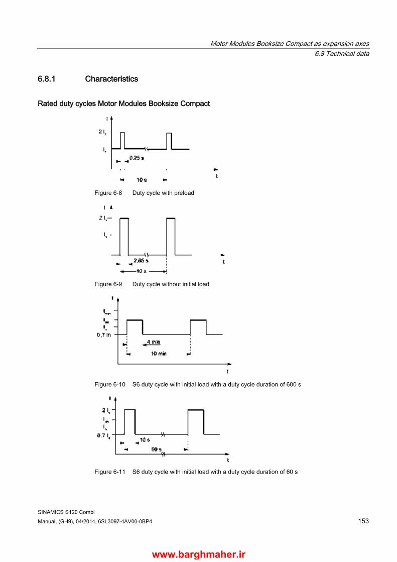
Motor Modules Booksize Compact as expansion axes 6.8 Technical data
SINAMICS S120 Combi Manual, (GH9), 04/2014, 6SL3097-4AV00-0BP4 153
6.8.1 Characteristics
Rated duty cycles Motor Modules Booksize Compact
Figure 6-8 Duty cycle with preload
Figure 6-9 Duty cycle without initial load
Figure 6-10 S6 duty cycle with initial load with a duty cycle duration of 600 s
Figure 6-11 S6 duty cycle with initial load with a duty cycle duration of 60 s
www.barghmaher.ir

Motor Modules Booksize Compact as expansion axes 6.8 Technical data
SINAMICS S120 Combi 154 Manual, (GH9), 04/2014, 6SL3097-4AV00-0BP4
Figure 6-12 Peak current duty cycle with initial load
Figure 6-13 Duty cycle with 60 s overload with a duty cycle duration of 300 s
Figure 6-14 Duty cycle with 30 s overload with a duty cycle duration of 300 s
www.barghmaher.ir
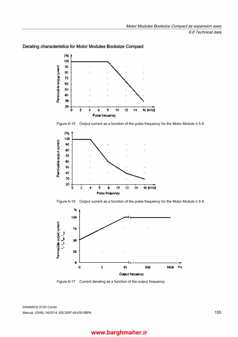
Motor Modules Booksize Compact as expansion axes 6.8 Technical data
SINAMICS S120 Combi Manual, (GH9), 04/2014, 6SL3097-4AV00-0BP4 155
Derating characteristics for Motor Modules Booksize Compact
Figure 6-15 Output current as a function of the pulse frequency for the Motor Module ≤ 5 A
Figure 6-16 Output current as a function of the pulse frequency for the Motor Module ≥ 9 A
Figure 6-17 Current derating as a function of the output frequency
www.barghmaher.ir

Motor Modules Booksize Compact as expansion axes 6.8 Technical data
SINAMICS S120 Combi 156 Manual, (GH9), 04/2014, 6SL3097-4AV00-0BP4
Note
You can find the following derating characteristics in Chapter Derating as a function of the installation altitude and ambient temperature (Page 32). • Output current as a function of the installation altitude • Output current as a function of the temperature
www.barghmaher.ir
SINAMICS S120 Combi Manual, (GH9), 04/2014, 6SL3097-4AV00-0BP4 157
DC link components 7 7.1 Control Supply Module CSM
7.1.1 Description The Control Supply Module provides an output voltage of 24 V - 28.8 V DC. The output voltage can be adjusted using an integrated potentiometer.
In normal operation, the Control Supply Module is supplied from the line voltage. In the event of a power failure, the module automatically changes over to supply from the DC link. This makes it possible, for example, to execute retraction movements in the event of a failure of the line supply.
The Control Supply Module has safe electrical separation between the line potential and the DC-link potential. This therefore ensures that the DC link is not unintentionally charged. The Control Supply Module can therefore remain connected to the line supply if the S120 Combi is electrically isolated from the line supply, for example via a line contactor.
The 24 V ground of the Control Supply Module is internally grounded. The Control Supply Module is cooled using an internal fan.
Temperature and voltages are internally monitored.
Temperature monitoring: In the event of an overtemperature in the Control Supply Module, a temperature advance warning is issued via a signaling contact. If the temperature falls below the limit value within the advance warning time, then the module remains operational and the signaling contact is de-energized. If the overtemperature condition persists, the module is switched off and restarted.
Voltage monitoring: When the monitoring threshold (32 V) of the output voltage is exceeded for > 20 ms, the control supply module switches off and attempts a restart after 10 s. This is supplemented by a hardware-based overvoltage limiting. This prevents that more than 35 V can be output in the case of a fault.
The Control Supply Module can either be operated individually or in a parallel connection with a maximum of 10 devices. The switchover between single and parallel operation is realized in a no-current state using a DIP switch on the upper side of the module.
Note Compatibility
The new Control Supply Module 6SL3100-1DE22-0AA1 with extended functions described here replaces Control Supply Module 6SL3100-1DE22-0AA0. The modules are spare-part-compatible.
www.barghmaher.ir

DC link components 7.1 Control Supply Module CSM
SINAMICS S120 Combi 158 Manual, (GH9), 04/2014, 6SL3097-4AV00-0BP4
7.1.2 Safety information
WARNING
Danger to life if the fundamental safety instructions and remaining risks are not carefully observed
If the fundamental safety instructions and remaining risks in Chapter 1 (Page 19) are not observed, accidents involving severe injuries or death may occur. • Adhere to the fundamental safety instructions. • When assessing the risk, take into account residual risks.
DANGER
Danger to life when live parts are touched when using the control supply module
The control supply module has two supply circuits. Death or serious injury can result when live parts are touched. • Switch off both supply circuits before you start any work.
DANGER
Danger to life through electric shock due to the residual charge of the DC link capacitors
Due to the DC link capacitors, a hazardous voltage is present in the DC link for up to five minutes after the power supply has been switched off.
Contact with live parts can result in death or serious injury. • Do not open the protective cover of the DC link until five minutes have elapsed. • Measure the voltage before starting work on the DCP and DCN DC link terminals.
DANGER
Danger to life through electric shock when the protective cover of the DC link is open
Contact with live parts can result in death or serious injury. • Only operate the components with closed protective cover.
WARNING
Danger to life through electric shock due to missing DC link side covers
There is a danger of an electric shock through contact when the side covers of the DC link are missing. • Mount the supplied side covers on the first and last component in the drive line-up.
You can order missing side covers (order number: 6SL3162-5AA00-0AA0).
www.barghmaher.ir

DC link components 7.1 Control Supply Module CSM
SINAMICS S120 Combi Manual, (GH9), 04/2014, 6SL3097-4AV00-0BP4 159
WARNING
Danger of an accident due to missing warning labels in the national language.
Missing warning labels in the national language regarding the DC link discharge time can result in death or serious injury. • Attach the component warning labels in the national language.
WARNING
Fire hazard due to overheating because of inadequate ventilation clearances
Inadequate ventilation clearances can cause overheating with a risk for personnel due to smoke and fire. This can also result in increased failure rates and a shorter service life for Line Modules. • It is absolutely essential that you maintain ventilation clearances according to the table
Ventilation clearances above and below the component (Page 312).
NOTICE
Material damage due to loose power connections
Insufficient tightening torques or vibrations can result in faulty electrical connections. This can cause fire damage or malfunctions. • Tighten all the DC link busbar screws with the specified tightening torques (1.8 Nm
tolerance +30 %). • Check the tightening torques of all power connections at regular intervals and tighten
them when required. This applies in particular after transport.
NOTICE
Material damage due to loose power connections when using the 24 V terminal adapter
Insufficient tightening torques or vibrations can result in faulty electrical connections. This can cause fire damage or malfunctions. • When using the 24 V terminal adapter, it must be screwed onto the Control Supply
Module Tighten the enclosed EJOT-PT screw K30 x 16 with the specified tightening torque (0.5 Nm).
• Check the tightening torques of all power connections at regular intervals and tighten them when required. This applies in particular after transport.
www.barghmaher.ir

DC link components 7.1 Control Supply Module CSM
SINAMICS S120 Combi 160 Manual, (GH9), 04/2014, 6SL3097-4AV00-0BP4
7.1.3 Interface description
7.1.3.1 Overview
Figure 7-1 Interface overview, Control Supply Module
www.barghmaher.ir
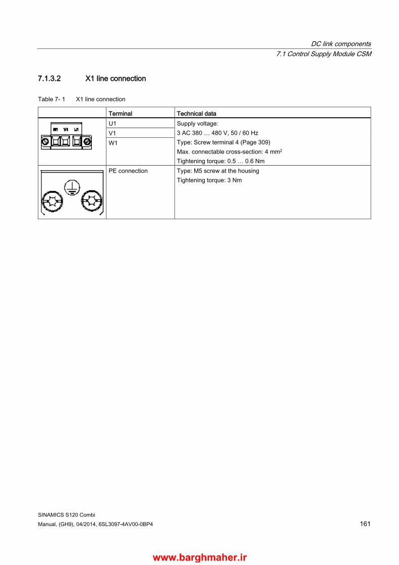
DC link components 7.1 Control Supply Module CSM
SINAMICS S120 Combi Manual, (GH9), 04/2014, 6SL3097-4AV00-0BP4 161
7.1.3.2 X1 line connection
Table 7- 1 X1 line connection
Terminal Technical data
U1 Supply voltage: 3 AC 380 … 480 V, 50 / 60 Hz Type: Screw terminal 4 (Page 309) Max. connectable cross-section: 4 mm2 Tightening torque: 0.5 … 0.6 Nm
V1 W1
PE connection Type: M5 screw at the housing Tightening torque: 3 Nm
www.barghmaher.ir
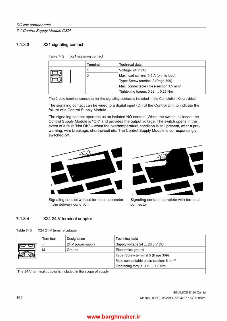
DC link components 7.1 Control Supply Module CSM
SINAMICS S120 Combi 162 Manual, (GH9), 04/2014, 6SL3097-4AV00-0BP4
7.1.3.3 X21 signaling contact
Table 7- 2 X21 signaling contact
Terminal Technical data
1 Voltage: 24 V DC Max. load current: 0.5 A (ohmic load) Type: Screw terminal 2 (Page 309) Max. connectable cross-section 1.5 mm2 Tightening torque: 0.22 … 0.25 Nm
2
The 2-pole terminal connector for the signaling contact is included in the Completion Kit provided.
The signaling contact can be wired to a digital input (DI) of the Control Unit to indicate the failure of a Control Supply Module.
The signaling contact operates as an isolated NO contact. When the switch is closed, the Control Supply Module is "OK" and provides the output voltage. The switch opens in the event of a fault "Not OK" – when the overtemperature condition is still present, after a pre-warning, wire breakage, short-circuit etc. The Control Supply Module is correspondingly switched off.
Signaling contact without terminal connector in the delivery condition
Signaling contact, complete with terminal connector
7.1.3.4 X24 24 V terminal adapter
Table 7- 3 X24 24 V terminal adapter
Terminal Designation Technical data
+ 24 V power supply Supply voltage 24 ... 28.8 V DC M Ground Electronics ground Type: Screw terminal 5 (Page 309)
Max. connectable cross-section: 6 mm2 Tightening torque: 1.5 … 1.8 Nm
The 24 V terminal adapter is included in the scope of supply.
www.barghmaher.ir
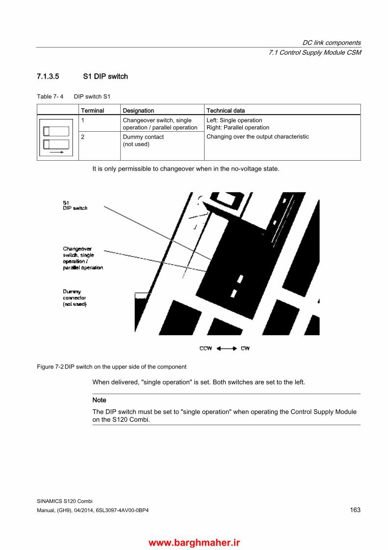
DC link components 7.1 Control Supply Module CSM
SINAMICS S120 Combi Manual, (GH9), 04/2014, 6SL3097-4AV00-0BP4 163
7.1.3.5 S1 DIP switch
Table 7- 4 DIP switch S1
Terminal Designation Technical data
1 Changeover switch, single operation / parallel operation
Left: Single operation Right: Parallel operation Changing over the output characteristic 2 Dummy contact
(not used)
It is only permissible to changeover when in the no-voltage state.
Figure 7-2 DIP switch on the upper side of the component
When delivered, "single operation" is set. Both switches are set to the left.
Note
The DIP switch must be set to "single operation" when operating the Control Supply Module on the S120 Combi.
www.barghmaher.ir
DC link components 7.1 Control Supply Module CSM
SINAMICS S120 Combi 164 Manual, (GH9), 04/2014, 6SL3097-4AV00-0BP4
7.1.4 Connection example The control supply module (CSM) is connected to the line supply (3-ph. 380 V AC –10 % to 480 V AC +10 %) via interface X1 (screw terminals 0.2 to 4 mm2) This connection should preferably be made without using an isolating device (e.g. contactor).
The CSM has an internal line filter (Class A for TN line supplies), and the pre-charging circuit for the DC link inside the unit is electrically isolated from the 24 V supply.
The CSM also features a current limitation function. When using cables with a cross-section of 2.5 mm2, no additional protection is required on the 24 V side if a type XLPE or EPR cable, or a cable with a similar quality and with a minimum thermal stability of up to 90 °C is used.
Note
If a selectively tripping, AC/DC-sensitive RCCB is used for the drive line-up, the Control Supply Module must always be connected to the line supply downstream of this circuit breaker.
Note Connecting to the line supply
When configuring the line supply for the Control Supply Module, it should be noted that the CSM must not be connected to the line supply after the S120 Combi has been connected to the line supply. When charging, this prevents the DC link from being immediately loaded by the CSM.
The DIP switch must be set to "single operation" to connect the Control Supply Module to the S120 Combi drive line-up. The connection can be established as shown below.
The CSM must be connected to the S120 Combi Power Module and the expansion axes via the DC link busbars as well as also via the 24 V busbars. It imperative to insert the red 24 V connector from the accessories pack provided.
www.barghmaher.ir
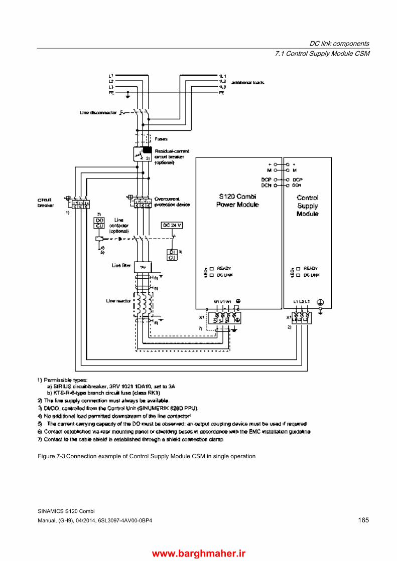
DC link components 7.1 Control Supply Module CSM
SINAMICS S120 Combi Manual, (GH9), 04/2014, 6SL3097-4AV00-0BP4 165
Figure 7-3 Connection example of Control Supply Module CSM in single operation
www.barghmaher.ir
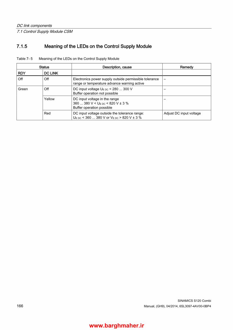
DC link components 7.1 Control Supply Module CSM
SINAMICS S120 Combi 166 Manual, (GH9), 04/2014, 6SL3097-4AV00-0BP4
7.1.5 Meaning of the LEDs on the Control Supply Module
Table 7- 5 Meaning of the LEDs on the Control Supply Module
Status Description, cause Remedy RDY DC LINK Off Off Electronics power supply outside permissible tolerance
range or temperature advance warning active –
Green Off DC input voltage UE DC < 280 ... 300 V Buffer operation not possible
–
Yellow DC input voltage in the range 360 ... 380 V < UE DC < 820 V ± 3 % Buffer operation possible
–
Red DC input voltage outside the tolerance range: UE DC < 360 ... 380 V or VE DC > 820 V ± 3 %
Adjust DC input voltage
www.barghmaher.ir

DC link components 7.1 Control Supply Module CSM
SINAMICS S120 Combi Manual, (GH9), 04/2014, 6SL3097-4AV00-0BP4 167
7.1.6 Dimension drawing
Figure 7-4 Dimension Control Supply Module, all dimensions in mm and (inches)
www.barghmaher.ir
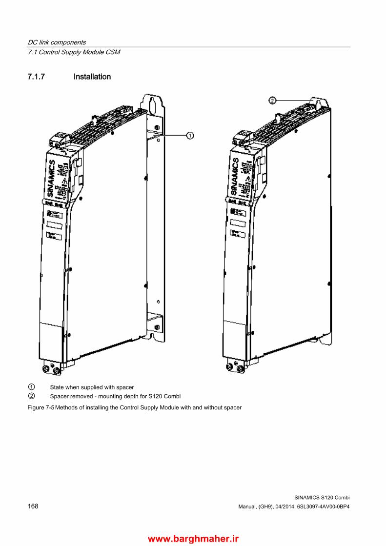
DC link components 7.1 Control Supply Module CSM
SINAMICS S120 Combi 168 Manual, (GH9), 04/2014, 6SL3097-4AV00-0BP4
7.1.7 Installation
① State when supplied with spacer ② Spacer removed - mounting depth for S120 Combi
Figure 7-5 Methods of installing the Control Supply Module with and without spacer
www.barghmaher.ir
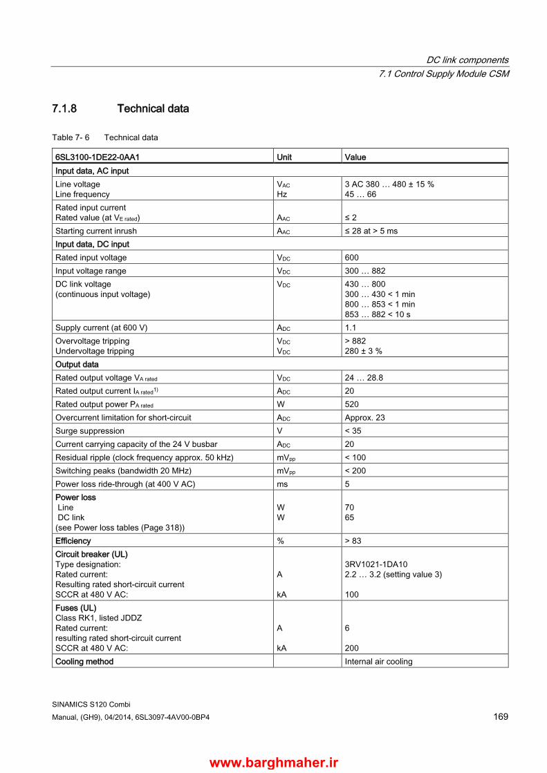
DC link components 7.1 Control Supply Module CSM
SINAMICS S120 Combi Manual, (GH9), 04/2014, 6SL3097-4AV00-0BP4 169
7.1.8 Technical data
Table 7- 6 Technical data
6SL3100-1DE22-0AA1 Unit Value Input data, AC input Line voltage Line frequency
VAC Hz
3 AC 380 … 480 ± 15 % 45 … 66
Rated input current Rated value (at VE rated)
AAC
≤ 2
Starting current inrush AAC ≤ 28 at > 5 ms Input data, DC input Rated input voltage VDC 600 Input voltage range VDC 300 … 882 DC link voltage (continuous input voltage)
VDC 430 … 800 300 … 430 < 1 min 800 … 853 < 1 min 853 … 882 < 10 s
Supply current (at 600 V) ADC 1.1 Overvoltage tripping Undervoltage tripping
VDC VDC
> 882 280 ± 3 %
Output data Rated output voltage VA rated VDC 24 … 28.8 Rated output current IA rated1) ADC 20 Rated output power PA rated W 520 Overcurrent limitation for short-circuit ADC Approx. 23 Surge suppression V < 35 Current carrying capacity of the 24 V busbar ADC 20 Residual ripple (clock frequency approx. 50 kHz) mVpp < 100 Switching peaks (bandwidth 20 MHz) mVpp < 200 Power loss ride-through (at 400 V AC) ms 5 Power loss Line DC link (see Power loss tables (Page 318))
W W
70 65
Efficiency % > 83 Circuit breaker (UL) Type designation: Rated current: Resulting rated short-circuit current SCCR at 480 V AC:
A kA
3RV1021-1DA10 2.2 … 3.2 (setting value 3) 100
Fuses (UL) Class RK1, listed JDDZ Rated current: resulting rated short-circuit current SCCR at 480 V AC:
A kA
6 200
Cooling method Internal air cooling
www.barghmaher.ir

DC link components 7.1 Control Supply Module CSM
SINAMICS S120 Combi 170 Manual, (GH9), 04/2014, 6SL3097-4AV00-0BP4
6SL3100-1DE22-0AA1 Unit Value Max. ambient temperature without derating with derating as of 26 V output voltage
° C ° C
≤ 40 > 40 … 55
Weight kg 4.8 1) Above 40° C, a linear derating of the output current above a 26 V output voltage and higher must be observed
7.1.8.1 Characteristics
Derating characteristic For ambient temperatures > 40 °C, a linear derating for the output current must be observed as of 26 output voltage.
Figure 7-6 Current derating for ambient temperatures >40 °C as a function of the output voltage
www.barghmaher.ir
DC link components 7.2 Braking Module Booksize
SINAMICS S120 Combi Manual, (GH9), 04/2014, 6SL3097-4AV00-0BP4 171
7.2 Braking Module Booksize
7.2.1 Description The Braking Module is used together with an external braking resistor for the following applications:
● For a power failure, the S120 Combi and expansion axes can be stopped in a controlled fashion (e.g. emergency retraction or EMERGENCY OFF Category 1).
● For brief generator operation, the DC link voltage can be limited, e.g. if the energy recovery function is deactivated or is not adequately dimensioned.
The Braking Module includes the necessary power electronics and control. When the Braking Module is in operation, the power which is fed back into the DC link is dissipated via an external braking resistor.
External braking resistors On the Braking Module, braking resistors can be operated without thermostatic switches 6SN1113-1AA00-0DA0 (PN = 0.3 kW) and 6SL3100-1BE31-0AA0 (PN = 1.5 kW). The cable length between the Braking Module and the braking resistor is limited to a maximum of 10 m.
A shielded connection cable (3 m, 3 x 1.5 mm2) is supplied with braking resistor 6SN1113-1AA00-0DA0.
Rapid discharge Furthermore, the Braking Module can used with a braking resistor to quickly discharge the DC link capacitors The DC link is discharged in a controlled manner via the braking resistor once the infeed unit has been switched off and the line-up has been disconnected from the line supply (e.g. via the main switch or line contactor). The function can be activated via a digital input on the braking module. A quick discharge makes sense, for example, when maintenance tasks are to be performed at the S120 Combi and/or motor installation (reduction of the discharge time).
WARNING
Danger to life when live parts are touched after rapid discharge
After rapid discharge or if discharge is interrupted, a hazardous voltage can still remain.
Death or serious injury can result when live parts are touched. • Check that it really is in a no-voltage condition, from phase conductor to phase
conductor and phase conductor to protective conductor.
www.barghmaher.ir
DC link components 7.2 Braking Module Booksize
SINAMICS S120 Combi 172 Manual, (GH9), 04/2014, 6SL3097-4AV00-0BP4
NOTICE
Material damage during fast discharge due to overvoltages
Existing voltages can damage the rapid discharge system. • Fully disconnect the drive system for rapid discharge from the line supply. • The motors must be at a standstill.
Monitoring functions ● Automatic detection of braking resistors and braking power monitoring
● I2t monitoring of the braking resistors
● Temperature monitoring of the Braking Module
● Short circuit and overload detection
● Ground fault detection
www.barghmaher.ir
DC link components 7.2 Braking Module Booksize
SINAMICS S120 Combi Manual, (GH9), 04/2014, 6SL3097-4AV00-0BP4 173
7.2.2 Safety information
WARNING
Danger to life if the fundamental safety instructions and remaining risks are not carefully observed
If the fundamental safety instructions and remaining risks in Chapter 1 (Page 19) are not observed, accidents involving severe injuries or death may occur. • Adhere to the fundamental safety instructions. • When assessing the risk, take into account residual risks.
DANGER
Danger to life through electric shock due to the residual charge of the DC link capacitors
Due to the DC link capacitors, a hazardous voltage is present in the DC link for up to five minutes after the power supply has been switched off. Contact with live parts can result in death or serious injury. • Do not open the protective cover of the DC link until five minutes have elapsed. • Only operate the S120 Combi with the DC link protective cover closed. • Do not continue to operate damaged components.
WARNING
Danger of an accident due to missing warning labels in the national language.
Missing warning labels in the national language regarding the DC link discharge time can result in death or serious injury. • Attach the component warning labels in the national language.
WARNING
Fire hazard due to overheating because of inadequate ventilation clearances
Inadequate ventilation clearances can cause overheating with a risk for personnel through smoke development and fire. This can also result in more downtimes and Line Modules may have a reduced service life. • It is absolutely essential that you maintain ventilation clearances according to the table
Ventilation clearances above and below the component (Page 312).
WARNING
Danger to life through electric shock due to missing DC link side covers
There is a danger of an electric shock through contact when the side covers of the DC link are missing. • Mount the supplied side covers on the first and last component in the drive line-up.
You can order missing side covers (order number: 6SL3162-5AA00-0AA0).
www.barghmaher.ir
DC link components 7.2 Braking Module Booksize
SINAMICS S120 Combi 174 Manual, (GH9), 04/2014, 6SL3097-4AV00-0BP4
NOTICE
Material damage due to loose power connections
Insufficient tightening torques or vibrations can result in faulty electrical connections. This can cause fire damage or malfunctions. • Tighten all the DC link busbar screws with the specified tightening torques (1.8 Nm
tolerance +30 %). • Check the tightening torques of all power connections at regular intervals and tighten
them when required. This applies in particular after transport.
Note
If braking resistors other than those described in Section Braking resistors (Page 184) (6SN1113-1AA00-0DA0 and 6SL3100-01BE31-0AAx) are used then these could be destroyed.
www.barghmaher.ir
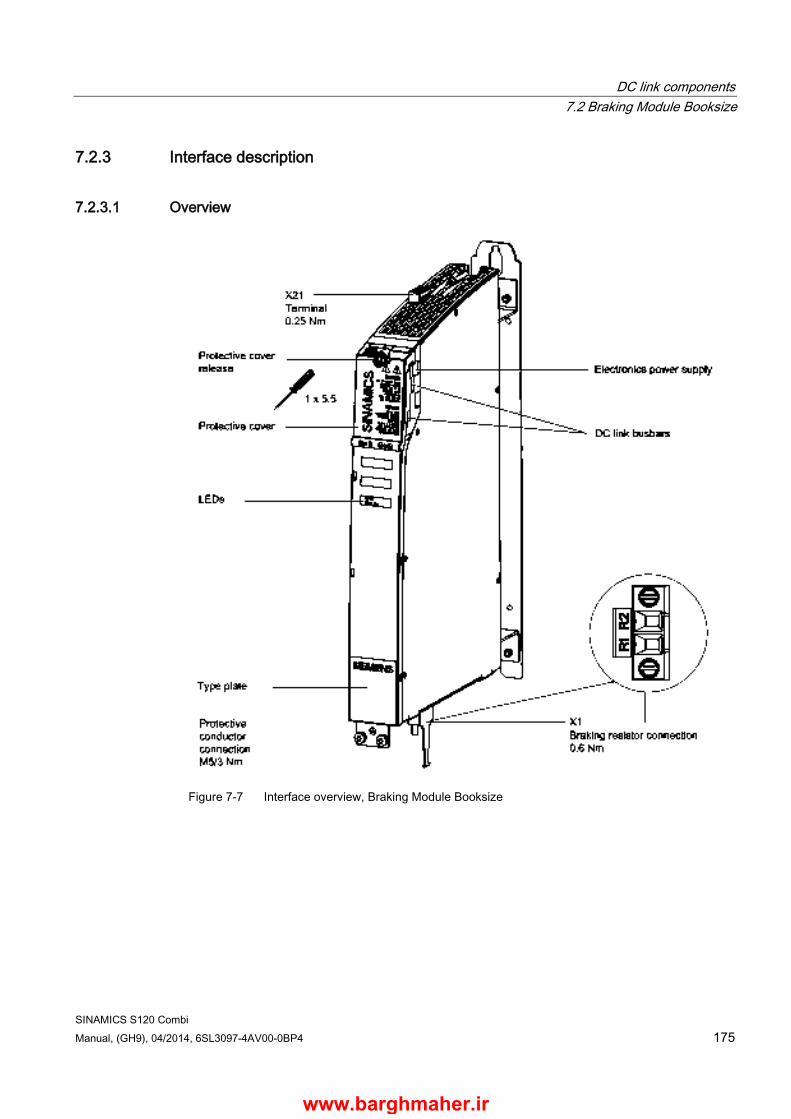
DC link components 7.2 Braking Module Booksize
SINAMICS S120 Combi Manual, (GH9), 04/2014, 6SL3097-4AV00-0BP4 175
7.2.3 Interface description
7.2.3.1 Overview
Figure 7-7 Interface overview, Braking Module Booksize
www.barghmaher.ir
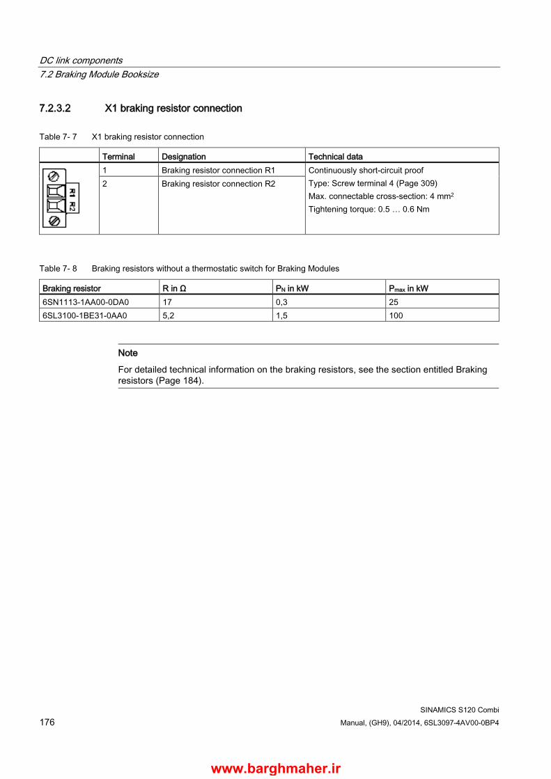
DC link components 7.2 Braking Module Booksize
SINAMICS S120 Combi 176 Manual, (GH9), 04/2014, 6SL3097-4AV00-0BP4
7.2.3.2 X1 braking resistor connection
Table 7- 7 X1 braking resistor connection
Terminal Designation Technical data
1 Braking resistor connection R1 Continuously short-circuit proof Type: Screw terminal 4 (Page 309) Max. connectable cross-section: 4 mm2 Tightening torque: 0.5 … 0.6 Nm
2 Braking resistor connection R2
Table 7- 8 Braking resistors without a thermostatic switch for Braking Modules
Braking resistor R in Ω PN in kW Pmax in kW 6SN1113-1AA00-0DA0 17 0,3 25 6SL3100-1BE31-0AA0 5,2 1,5 100
Note
For detailed technical information on the braking resistors, see the section entitled Braking resistors (Page 184).
www.barghmaher.ir

DC link components 7.2 ,Braking Module Booksize
SINAMICS S120 Combi Manual, (GH9), 04/2014, 6SL3097-4AV00-0BP4 177
7.2.3.3 X21 digital inputs/outputs
Table 7- 9 X21 digital inputs/outputs
Terminal Designation 1) Technical data
1 DI low: enable Braking Module DI high: Inhibit/acknowledge Edge change, high → low: fault acknowledgement
Voltage: -3 … +30 V Current consumption, typical: 10 mA at 24 V DC Level (incl. ripple) High level: 15 … 30 V Low level: -3 … +5 V
2 DI low: braking resistor not activated manually DI high: Braking resistor controlled manually (quick discharge) 2) If X21.1 and X21.2 are activated simultaneously, the Braking Module inhibit has priority.
3 DO high: no prewarning DO low: Prewarning, disconnection imminent
Max. load current per output: 100 mA Continuously short-circuit proof Voltage: 24 V DC 4 DO high: ready for operation, no fault
DO low: Fault (1→0) 5 Ground 6 Type: Screw terminal 1 (Page 309)
Max. connectable cross-section 1.5 mm2 Tightening torque: 0.22 … 0.25 Nm
1) DI: digital input; DO: digital output; M: Electronics ground 2) The fast discharge function is used for discharging the capacitors in the DC link after interruption of the line supply and
may be used a maximum of 1 to 2 times per week.
Terminal X21.1 - inhibit/acknowledge
Applying a high signal to terminal X21.1 inhibits the Braking Module. On a falling edge, pending error signals are acknowledged.
Terminal X21.3 - prewarning
When a prewarning is sent, disconnection of the braking module is imminent.
This may be due to the following causes:
● The temperature of the Braking Module is 80 % of the maximum value.
● 80 % of the maximum on-load factor of the braking resistor has been reached (I2t monitoring).
● 80 % of the maximum braking energy of the braking resistor has been reached.
● An incorrect braking resistor is connected (only braking resistors approved by Siemens for this component are identified automatically).
Terminal X21.4 - fault
In the event of an overtemperature, the error cannot be acknowledged until after a cooling phase.
www.barghmaher.ir
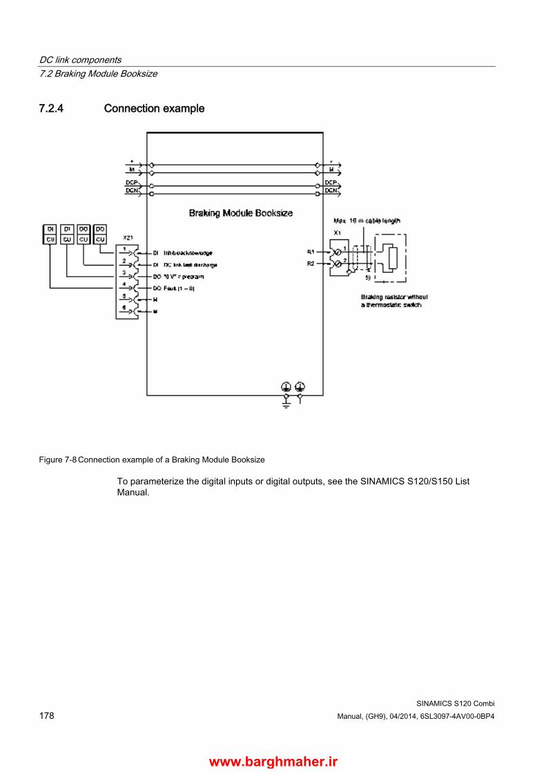
DC link components 7.2 Braking Module Booksize
SINAMICS S120 Combi 178 Manual, (GH9), 04/2014, 6SL3097-4AV00-0BP4
7.2.4 Connection example
Figure 7-8 Connection example of a Braking Module Booksize
To parameterize the digital inputs or digital outputs, see the SINAMICS S120/S150 List Manual.
www.barghmaher.ir

DC link components 7.2 Braking Module Booksize
SINAMICS S120 Combi Manual, (GH9), 04/2014, 6SL3097-4AV00-0BP4 179
7.2.5 Meaning of the LEDs
Table 7- 10 Meaning of the LEDs on the Braking Module Booksize
Status Description, cause Remedy RDY DC LINK Off Off Electronics power supply is missing or outside the
permissible tolerance range. Component not active or has been deactivated via the terminal.
–
Green Off Component is ready for operation. Electronics power supply is missing or outside the permissible tolerance range. Component not active.
–
Green flashing light
Component active (DC link discharge via braking resistor in progress).
–
Red Off Approval missing (input terminal) Overtemperature Overcurrent trip I2t-monitoring activated Ground fault/short circuit Note: In the event of overtemperature, the error cannot be acknowledged until after a cooling phase.
Diagnose fault (via output terminals) and acknowledge it (via input terminal)
www.barghmaher.ir

DC link components 7.2 Braking Module Booksize
SINAMICS S120 Combi 180 Manual, (GH9), 04/2014, 6SL3097-4AV00-0BP4
7.2.6 Dimension drawing
Figure 7-9 Dimension drawing of Braking Module, all dimensions in mm and (inches)
www.barghmaher.ir

DC link components 7.2 Braking Module Booksize
SINAMICS S120 Combi Manual, (GH9), 04/2014, 6SL3097-4AV00-0BP4 181
7.2.7 Installation
① State when supplied with spacer ② Spacer removed - mounting depth for S120 Combi
Figure 7-10 Methods of installing Braking Modules with/without spacer elements
www.barghmaher.ir

DC link components 7.2 Braking Module Booksize
SINAMICS S120 Combi 182 Manual, (GH9), 04/2014, 6SL3097-4AV00-0BP4
7.2.8 Technical data
Table 7- 11 Technical data
6SL3100-1AE31-0ABx DC link voltage VDC 510 … 720 DC link capacitance µF 110 ON threshold V 770 Electronics power supply VDC 24 (20.4 … 28.8) Electronics current drawn (at 24 V DC) ADC 0.5 Current carrying capacity DC link busbars 24 V busbars
ADC ADC
100 20
Braking power Max. Continuous braking power
kW kW
100 1.5
Power loss (see power loss tables (Page 318))
W 20
Cooling method Natural convection Weight kg 4,1
7.2.8.1 Characteristic curves
Duty cycle for braking resistors without a thermostatic switch
Figure 7-11 Duty cycle for braking resistors without a thermostatic switch
T [s] time period of braking duty cycle
A [s] load duration
PN [W] rated power (continuous power) of braking resistor
Pmax [W] peak power of braking resistor (6 x PN)
www.barghmaher.ir
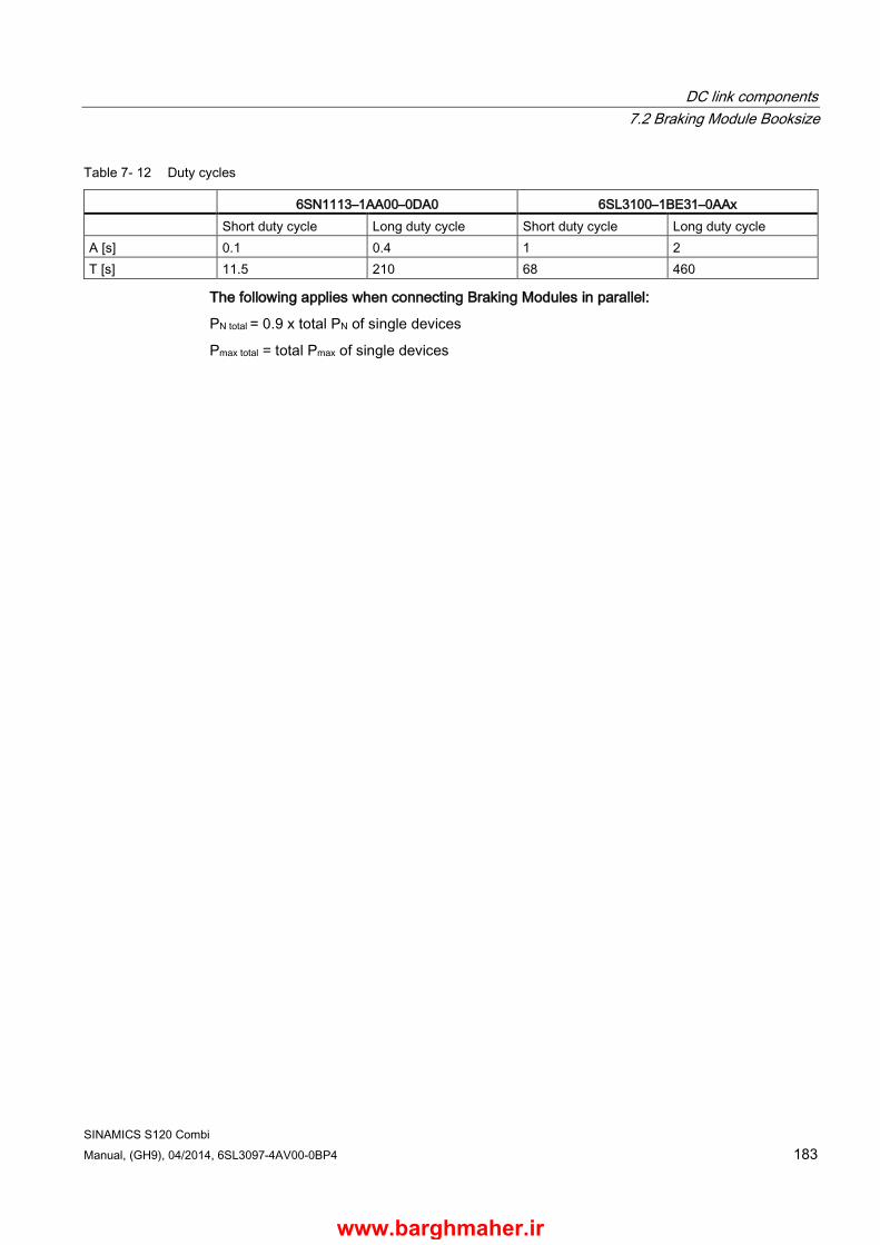
DC link components 7.2 Braking Module Booksize
SINAMICS S120 Combi Manual, (GH9), 04/2014, 6SL3097-4AV00-0BP4 183
Table 7- 12 Duty cycles
6SN1113–1AA00–0DA0 6SL3100–1BE31–0AAx Short duty cycle Long duty cycle Short duty cycle Long duty cycle A [s] 0.1 0.4 1 2 T [s] 11.5 210 68 460
The following applies when connecting Braking Modules in parallel:
PN total = 0.9 x total PN of single devices
Pmax total = total Pmax of single devices
www.barghmaher.ir
DC link components 7.3 Braking resistors
SINAMICS S120 Combi 184 Manual, (GH9), 04/2014, 6SL3097-4AV00-0BP4
7.3 Braking resistors
7.3.1 Description A braking resistor is used to dissipate the excess DC link energy in generator operation. One braking resistor is connected to one Braking Module.
Resistors without thermostatic switch are available with various power ratings.
Installation The braking resistors can be installed standing on the floor of the control cabinet or suspended. You must ensure that the braking resistors do not obstruct the flow of cooling air to the drive line-up.
Positioning the braking resistor outside the control cabinet or switchgear room enables the resulting thermal losses to be routed away. This reduces the level of air conditioning required.
Connecting cables A shielded connection cable (3 m, 3 x 1.5 mm2) is supplied with braking resistor 6SN1113-1AA00-0DA0.
Other braking resistors are supplied without connecting cable. The maximum conductor cross-sections are listed in the technical data.
The maximum cable length for all braking resistors is 10 m.
www.barghmaher.ir
DC link components 7.3 Braking resistors
SINAMICS S120 Combi Manual, (GH9), 04/2014, 6SL3097-4AV00-0BP4 185
7.3.2 Safety information
WARNING
Danger to life if the fundamental safety instructions and remaining risks are not carefully observed
If the fundamental safety instructions and remaining risks in Chapter 1 (Page 19) are not observed, accidents involving severe injuries or death may occur. • Adhere to the fundamental safety instructions. • When assessing the risk, take into account residual risks.
WARNING
Fire hazard and device damage as a result of ground fault/short-circuit
The cables to the braking resistor must be routed so that a ground fault or short-circuit can be ruled out. A ground fault can result in fire with associated smoke. • Comply with local installation regulations that enable this fault to be ruled out. • Protect the cables from mechanical damage. • In addition, apply one of the following measures:
– Use cables with double insulation. – Maintain adequate clearance, e.g. using spacers. – Route the cables in separate cable ducts or pipes.
CAUTION
Risk of burns resulting from high surface temperatures
The braking resistor can become very hot. You can be severely burnt when touching the surface. • Mount the braking resistor so that it cannot be touched. If this is not possible, attach a
clearly visible and understandable warning notice at hazardous positions. • To prevent adjacent components from suffering damage due to these high
temperatures, maintain a clearance of 100 mm on all sides of the braking resistor.
www.barghmaher.ir
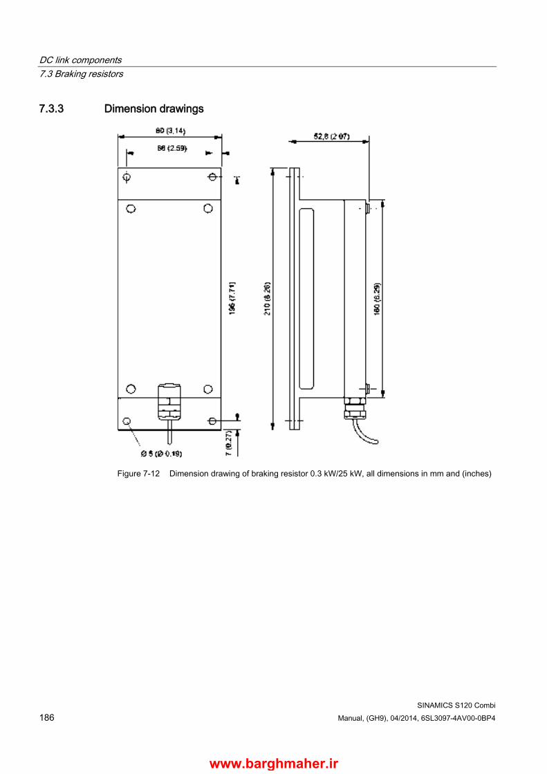
DC link components 7.3 Braking resistors
SINAMICS S120 Combi 186 Manual, (GH9), 04/2014, 6SL3097-4AV00-0BP4
7.3.3 Dimension drawings
Figure 7-12 Dimension drawing of braking resistor 0.3 kW/25 kW, all dimensions in mm and (inches)
www.barghmaher.ir
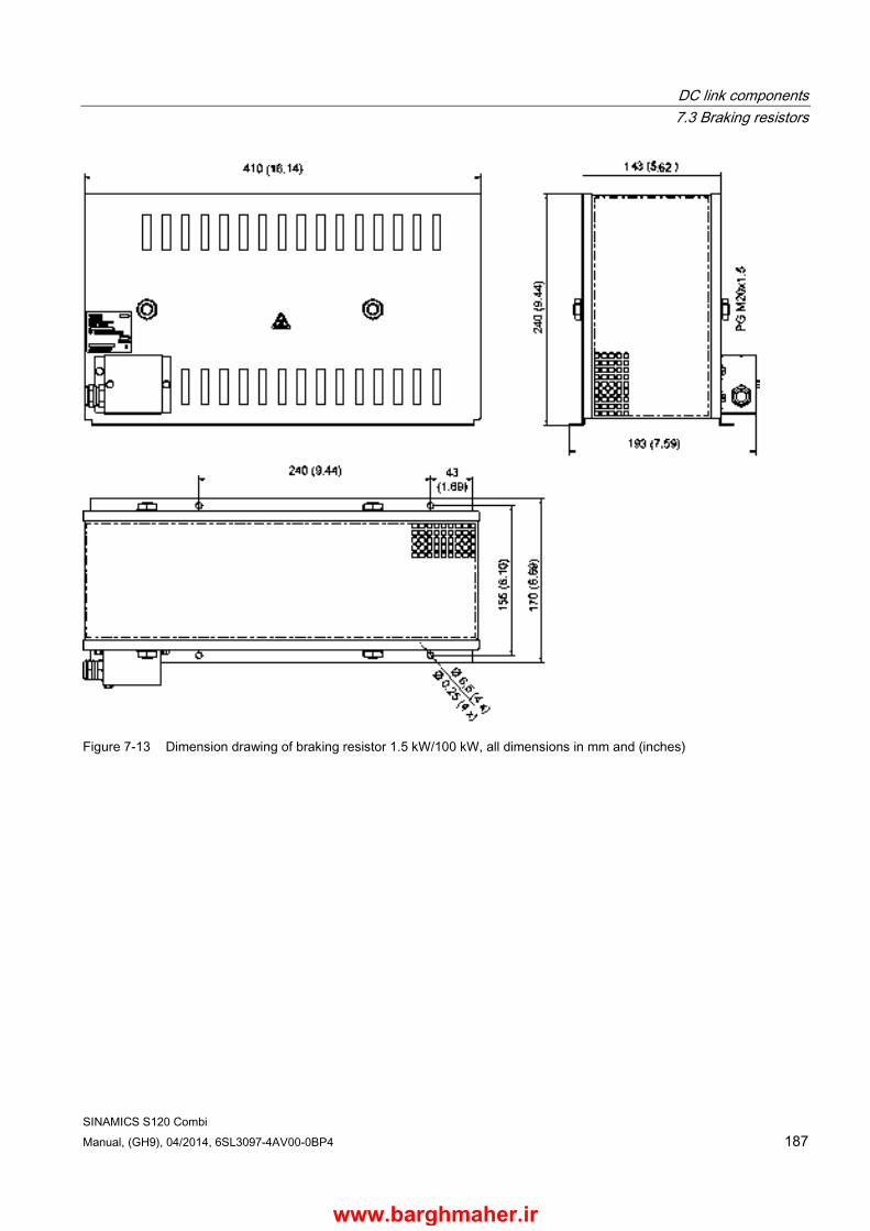
DC link components 7.3 Braking resistors
SINAMICS S120 Combi Manual, (GH9), 04/2014, 6SL3097-4AV00-0BP4 187
Figure 7-13 Dimension drawing of braking resistor 1.5 kW/100 kW, all dimensions in mm and (inches)
www.barghmaher.ir
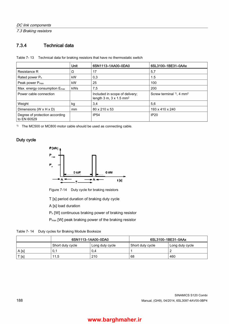
DC link components 7.3 Braking resistors
SINAMICS S120 Combi 188 Manual, (GH9), 04/2014, 6SL3097-4AV00-0BP4
7.3.4 Technical data
Table 7- 13 Technical data for braking resistors that have no thermostatic switch
Unit 6SN1113–1AA00–0DA0 6SL3100–1BE31–0AAx Resistance R Ω 17 5,7 Rated power Pn kW 0,3 1.5 Peak power Pmax kW 25 100 Max. energy consumption Emax kWs 7,5 200 Power cable connection Included in scope of delivery;
length 3 m, 3 x 1.5 mm2 Screw terminal 1), 4 mm2
Weight kg 3,4 5,6 Dimensions (W x H x D) mm 80 x 210 x 53 193 x 410 x 240 Degree of protection according to EN 60529
IP54 IP20
1) The MC500 or MC800 motor cable should be used as connecting cable.
Duty cycle
Figure 7-14 Duty cycle for braking resistors
T [s] period duration of braking duty cycle
A [s] load duration
Pn [W] continuous braking power of braking resistor
Pmax [W] peak braking power of the braking resistor
Table 7- 14 Duty cycles for Braking Module Booksize
6SN1113–1AA00–0DA0 6SL3100–1BE31–0AAx Short duty cycle Long duty cycle Short duty cycle Long duty cycle A [s] 0,1 0,4 1 2 T [s] 11,5 210 68 460
www.barghmaher.ir
SINAMICS S120 Combi Manual, (GH9), 04/2014, 6SL3097-4AV00-0BP4 189
Electrically connecting Motor Modules and DC link components 8 8.1 Introduction
The S120 Combi offers the possibility of connecting the following expansion axes and DC link components to the DC link and the 24 V electronics power supply:
● Motor Modules Booksize Compact
● Braking Module
● Control Supply Module
For the S120 Combi, the DC link connection and the 24 V busbars are located at the front behind the front plate. Signal and power cables from the additional components should be connected according to the Sections Motor Modules Booksize Compact as expansion axes (Page 135) and DC link components (Page 157).
www.barghmaher.ir
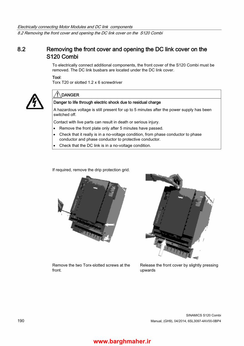
Electrically connecting Motor Modules and DC link components8.2 Removing the front cover and opening the DC link cover on the S120 Combi
SINAMICS S120 Combi 190 Manual, (GH9), 04/2014, 6SL3097-4AV00-0BP4
8.2 Removing the front cover and opening the DC link cover on the S120 Combi
To electrically connect additional components, the front cover of the S120 Combi must be removed. The DC link busbars are located under the DC link cover.
Tool: Torx T20 or slotted 1.2 x 6 screwdriver
DANGER
Danger to life through electric shock due to residual charge
A hazardous voltage is still present for up to 5 minutes after the power supply has been switched off.
Contact with live parts can result in death or serious injury. • Remove the front plate only after 5 minutes have passed. • Check that it really is in a no-voltage condition, from phase conductor to phase
conductor and phase conductor to protective conductor. • Check that the DC link is in a no-voltage condition.
If required, remove the drip protection grid.
Remove the two Torx-slotted screws at the front.
Release the front cover by slightly pressing upwards
www.barghmaher.ir

Electrically connecting Motor Modules and DC link components 8.2 Removing the front cover and opening the DC link cover on the S120 Combi
SINAMICS S120 Combi Manual, (GH9), 04/2014, 6SL3097-4AV00-0BP4 191
Remove the front plate. Remove the Torx-slotted screw of the DC link cover.
Remove the DC link cover. Remove the DC link side cover.
www.barghmaher.ir

Electrically connecting Motor Modules and DC link components8.3 Connection of DC link busbars and 24 V busbars
SINAMICS S120 Combi 192 Manual, (GH9), 04/2014, 6SL3097-4AV00-0BP4
8.3 Connection of DC link busbars and 24 V busbars The following steps are necessary to connect a component to the DC link and the 24 V busbars of the S120 Combi:
1. Use a suitable screwdriver or tool from the accessories pack to open the protective cover of the component which is to be connected.
2. Remove the DC link side cover at the connection location.
Figure 8-1 S120 Combi and Motor Module without DC link covers
3. Install the lower and upper DC link busbars.
Install the lower DC link busbar Install the upper DC link busbar
• Release the screws. • Turn over the DC link bridge. • Observe the following sequence when
screwing into place.
• Release the screws. • Turn over the DC link bridge. • Observe the following sequence when
screwing into place.
Screwdriver Torx T20 or slotted 1.2 x 6 Tightening torque 1.8 Nm
www.barghmaher.ir

Electrically connecting Motor Modules and DC link components 8.3 Connection of DC link busbars and 24 V busbars
SINAMICS S120 Combi Manual, (GH9), 04/2014, 6SL3097-4AV00-0BP4 193
4. Install the red 24 V connector (accessories pack of the component to be connected).
Figure 8-2 S120 Combi and Motor Module with installed 24 V connector
5. Close the protective cover of the connected component.
6. Mount the front plate on the S120 Combi.
DANGER
Danger to life due to electric shock in the event of missing touch protection
Death or serious injury can result when live parts are touched. • After removing the additional components, before recommissioning the system, you
must reinstall the lateral DC link cover on the S120 Combi Power Module. The DC link lateral cover can be ordered as a spare part (order number: 6SL3161-3AP00-0AA0).
WARNING
Danger to life through electric shock due to missing DC link side covers, protective cover or front plate
There is a danger of an electric shock through contact when the side covers, protective cover or front plate of the DC link are missing. • Mount the supplied side covers on the first and last component in the drive line-up.
You can order missing side covers (order number: 6SL3162-5AA00-0AA0). • Close the protective cover of the connected component. • Mount the front plate on the S120 Combi.
www.barghmaher.ir

Electrically connecting Motor Modules and DC link components8.3 Connection of DC link busbars and 24 V busbars
SINAMICS S120 Combi 194 Manual, (GH9), 04/2014, 6SL3097-4AV00-0BP4
WARNING
Danger to life due to electric shock when connecting and disconnecting 24 V connections in operation
When opening plug connections in operation, arcs can result in severe injury or death. • Only withdraw or insert the 24 V connectors in a no-voltage state. • It is only permissible to withdraw or insert the 24 V connectors a maximum of 5 times.
www.barghmaher.ir
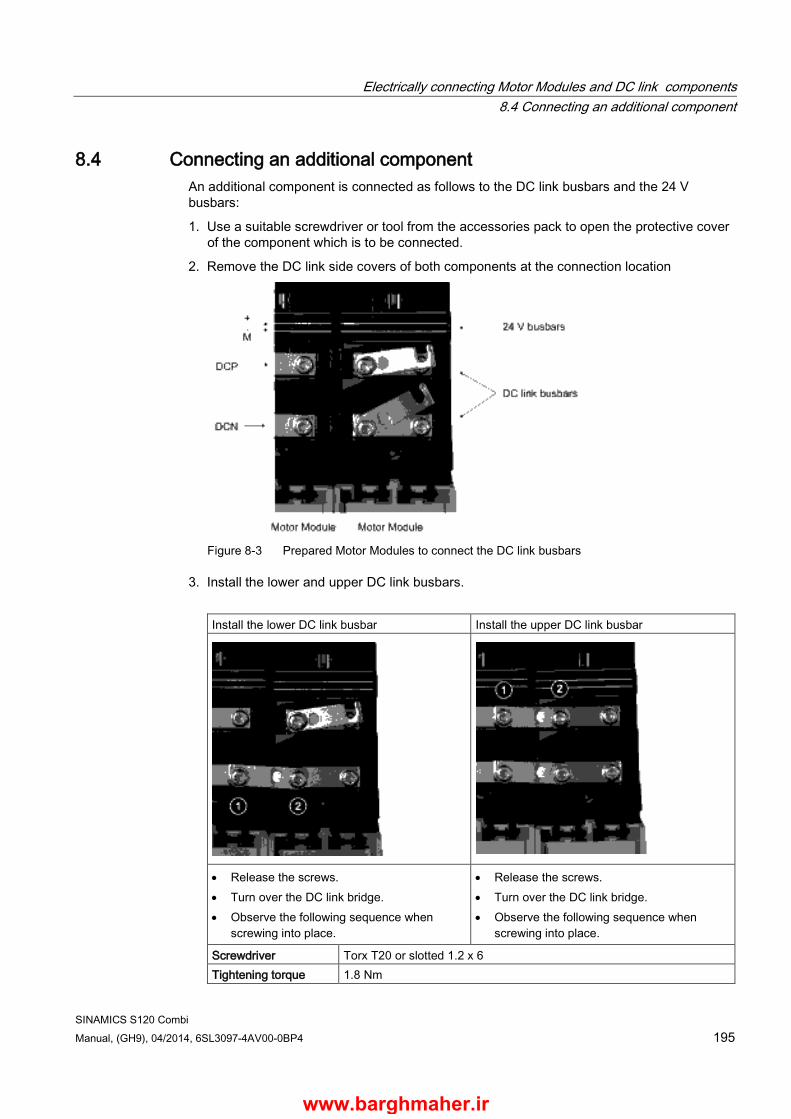
Electrically connecting Motor Modules and DC link components 8.4 Connecting an additional component
SINAMICS S120 Combi Manual, (GH9), 04/2014, 6SL3097-4AV00-0BP4 195
8.4 Connecting an additional component An additional component is connected as follows to the DC link busbars and the 24 V busbars:
1. Use a suitable screwdriver or tool from the accessories pack to open the protective cover of the component which is to be connected.
2. Remove the DC link side covers of both components at the connection location
Figure 8-3 Prepared Motor Modules to connect the DC link busbars
3. Install the lower and upper DC link busbars.
Install the lower DC link busbar Install the upper DC link busbar
• Release the screws. • Turn over the DC link bridge. • Observe the following sequence when
screwing into place.
• Release the screws. • Turn over the DC link bridge. • Observe the following sequence when
screwing into place.
Screwdriver Torx T20 or slotted 1.2 x 6 Tightening torque 1.8 Nm
www.barghmaher.ir
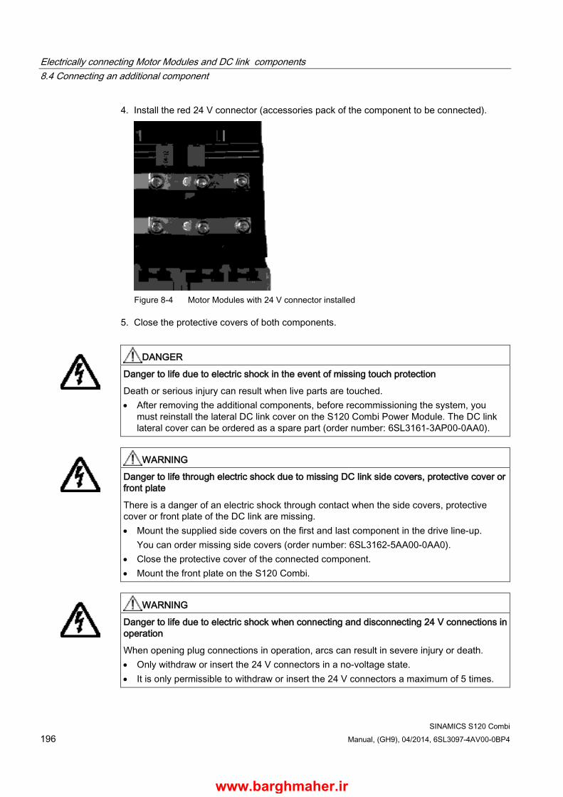
Electrically connecting Motor Modules and DC link components8.4 Connecting an additional component
SINAMICS S120 Combi 196 Manual, (GH9), 04/2014, 6SL3097-4AV00-0BP4
4. Install the red 24 V connector (accessories pack of the component to be connected).
Figure 8-4 Motor Modules with 24 V connector installed
5. Close the protective covers of both components.
DANGER
Danger to life due to electric shock in the event of missing touch protection
Death or serious injury can result when live parts are touched. • After removing the additional components, before recommissioning the system, you
must reinstall the lateral DC link cover on the S120 Combi Power Module. The DC link lateral cover can be ordered as a spare part (order number: 6SL3161-3AP00-0AA0).
WARNING
Danger to life through electric shock due to missing DC link side covers, protective cover or front plate
There is a danger of an electric shock through contact when the side covers, protective cover or front plate of the DC link are missing. • Mount the supplied side covers on the first and last component in the drive line-up.
You can order missing side covers (order number: 6SL3162-5AA00-0AA0). • Close the protective cover of the connected component. • Mount the front plate on the S120 Combi.
WARNING
Danger to life due to electric shock when connecting and disconnecting 24 V connections in operation
When opening plug connections in operation, arcs can result in severe injury or death. • Only withdraw or insert the 24 V connectors in a no-voltage state. • It is only permissible to withdraw or insert the 24 V connectors a maximum of 5 times.
www.barghmaher.ir

SINAMICS S120 Combi Manual, (GH9), 04/2014, 6SL3097-4AV00-0BP4 197
Additional system components 9 9.1 Terminal Module TM54F
9.1.1 Description The Terminal Module TM54F is a terminal expansion module for snapping onto an EN 60715 DIN rail. The TM54F offers safe digital inputs and outputs for controlling SINAMICS Safety Integrated functions.
The TM54F must be directly connected to the PPU of SINUMERIK 828D via DRIVE-CLiQ. In so doing, the topology rules must be observed.
TM54F features the following interfaces:
Table 9- 1 Interface overview of the TM54F
Type Number DRIVE-CLiQ interfaces 2 Fail-safe digital outputs (F-DO) 4 Fail-safe digital inputs (F-DI) 10 Sensor1) power supplies, dynamization supported 2) 2 Sensor1) power supply, no dynamization 1 Digital inputs for testing the F-DO at test stop 4 1) Sensors: Fail-safe devices to issue commands and sense - for example, Emergency Stop buttons
and safety locks, position switches and light arrays/light curtains. 2) Forced checking procedure: The sensor power supply is cycled on and off by the TM54F when the
forced checking procedure is active for the sensors, cable routing, and the evaluation electronics.
The TM54F has 4 fail-safe digital outputs and 10 fail-safe digital inputs.
A fail-safe digital output comprises:
● An output switching to 24 V
● An output switching to ground
● Digital input to check the switching state
A fail-safe digital input comprises:
● 2 digital inputs
www.barghmaher.ir
Additional system components 9.1 Terminal Module TM54F
SINAMICS S120 Combi 198 Manual, (GH9), 04/2014, 6SL3097-4AV00-0BP4
Note
The rated values of the F-DO meet the requirements of EN 61131-2 for digital DC outputs with 0.5 A rated current.
The operating ranges of the F-DI meet the requirements of EN 61131-2 for Type 1 digital inputs.
Note
If the length of the F-DI is > 30 m, then shielded cables must be used for the F-DI.
9.1.2 Safety information
WARNING
Fire hazard due to overheating because of inadequate ventilation clearances
Inadequate ventilation clearances can cause overheating with a risk for personnel due to smoke and fire. This can also result in increased failure rates and a shorter service life for Terminal Modules. • It is absolutely essential that you maintain ventilation clearances according to the table
Ventilation clearances above and below the component (Page 312).
www.barghmaher.ir
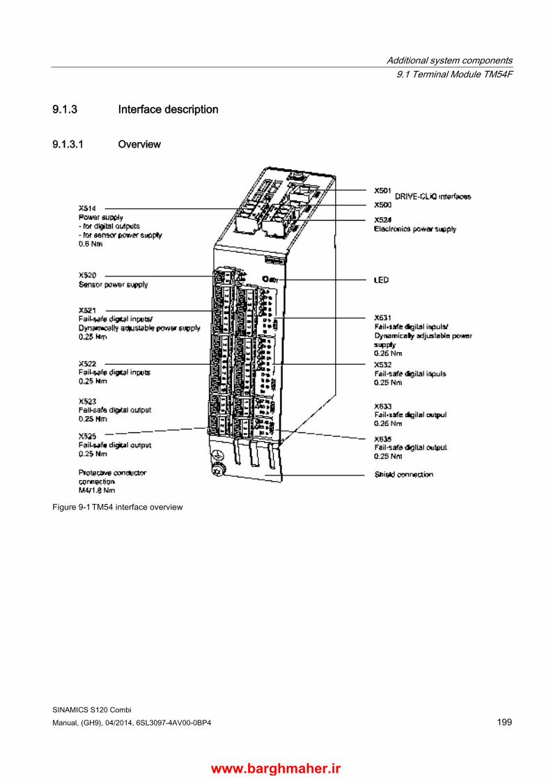
Additional system components 9.1 Terminal Module TM54F
SINAMICS S120 Combi Manual, (GH9), 04/2014, 6SL3097-4AV00-0BP4 199
9.1.3 Interface description
9.1.3.1 Overview
Figure 9-1 TM54 interface overview
www.barghmaher.ir
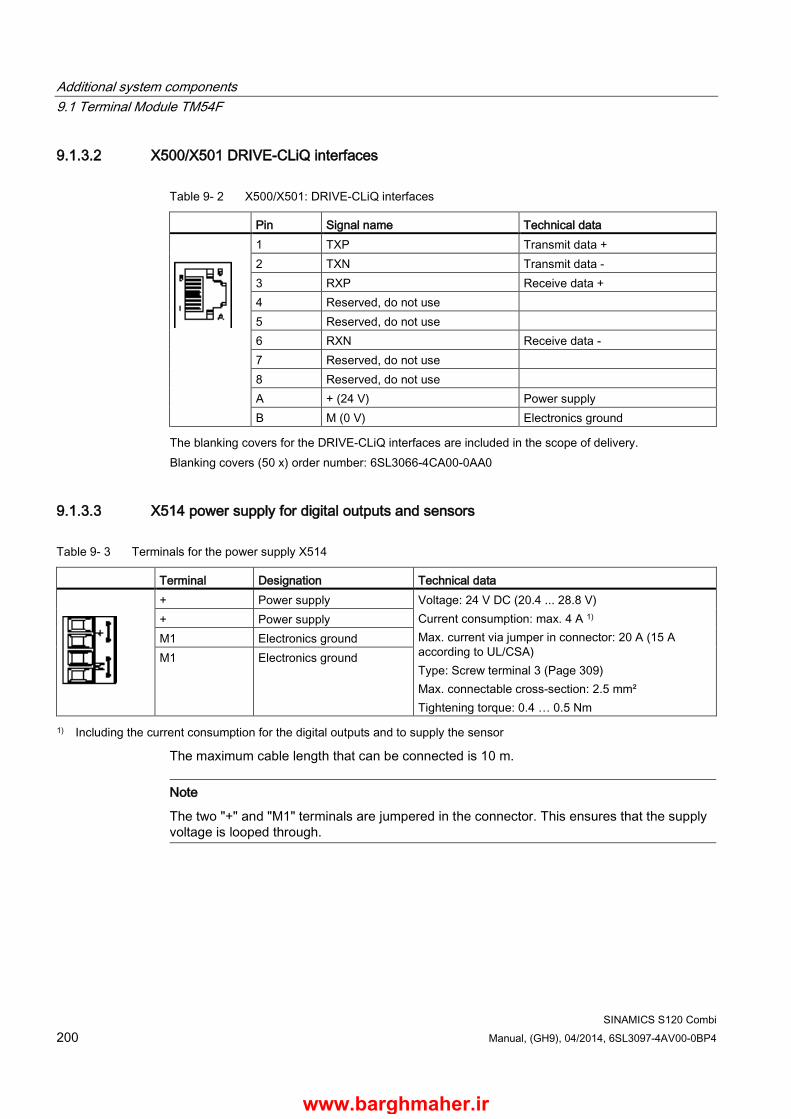
Additional system components 9.1 Terminal Module TM54F
SINAMICS S120 Combi 200 Manual, (GH9), 04/2014, 6SL3097-4AV00-0BP4
9.1.3.2 X500/X501 DRIVE-CLiQ interfaces
Table 9- 2 X500/X501: DRIVE-CLiQ interfaces
Pin Signal name Technical data
1 TXP Transmit data + 2 TXN Transmit data - 3 RXP Receive data + 4 Reserved, do not use 5 Reserved, do not use 6 RXN Receive data - 7 Reserved, do not use 8 Reserved, do not use A + (24 V) Power supply B M (0 V) Electronics ground
The blanking covers for the DRIVE-CLiQ interfaces are included in the scope of delivery. Blanking covers (50 x) order number: 6SL3066-4CA00-0AA0
9.1.3.3 X514 power supply for digital outputs and sensors
Table 9- 3 Terminals for the power supply X514
Terminal Designation Technical data
+ Power supply Voltage: 24 V DC (20.4 ... 28.8 V) Current consumption: max. 4 A 1) Max. current via jumper in connector: 20 A (15 A according to UL/CSA) Type: Screw terminal 3 (Page 309) Max. connectable cross-section: 2.5 mm² Tightening torque: 0.4 … 0.5 Nm
+ Power supply M1 Electronics ground M1 Electronics ground
1) Including the current consumption for the digital outputs and to supply the sensor
The maximum cable length that can be connected is 10 m.
Note
The two "+" and "M1" terminals are jumpered in the connector. This ensures that the supply voltage is looped through.
www.barghmaher.ir
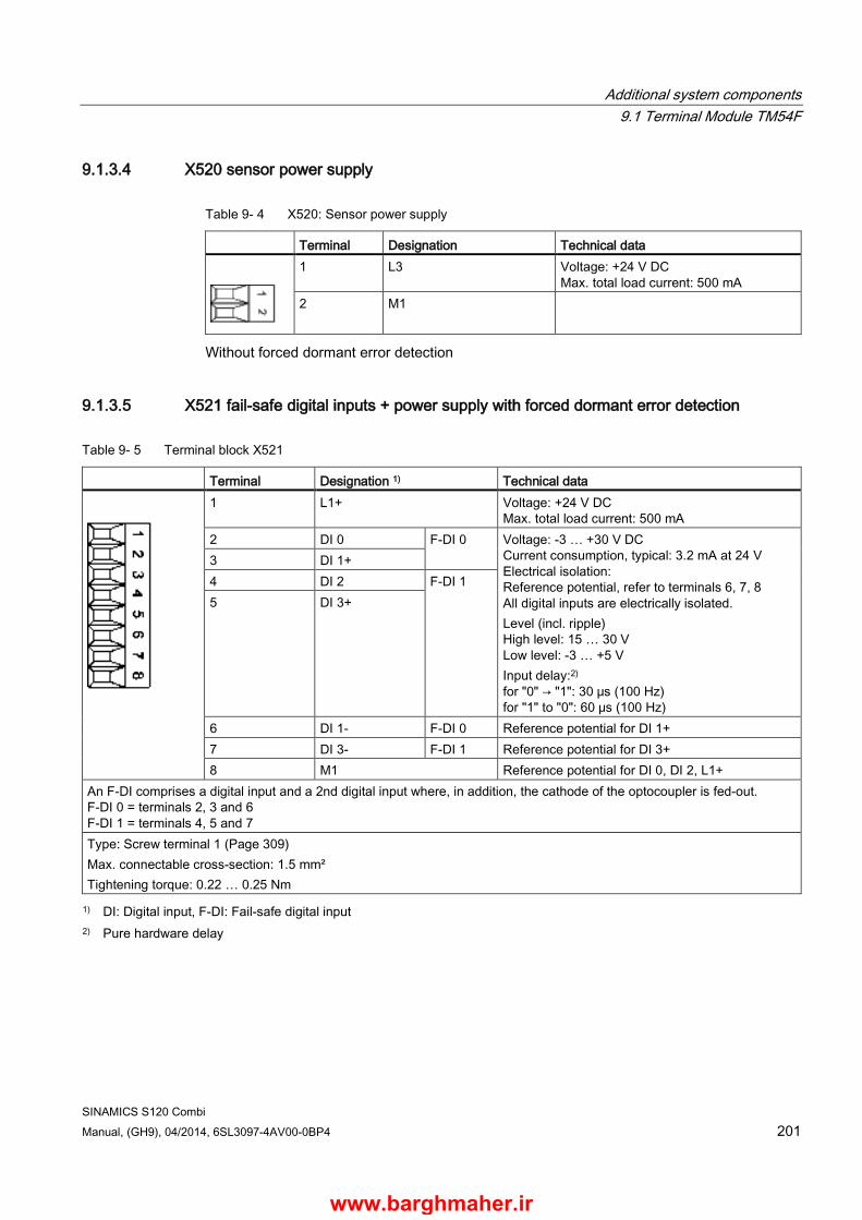
Additional system components 9.1 Terminal Module TM54F
SINAMICS S120 Combi Manual, (GH9), 04/2014, 6SL3097-4AV00-0BP4 201
9.1.3.4 X520 sensor power supply
Table 9- 4 X520: Sensor power supply
Terminal Designation Technical data
1 L3 Voltage: +24 V DC Max. total load current: 500 mA
2 M1
Without forced dormant error detection
9.1.3.5 X521 fail-safe digital inputs + power supply with forced dormant error detection
Table 9- 5 Terminal block X521
Terminal Designation 1) Technical data
1 L1+ Voltage: +24 V DC Max. total load current: 500 mA
2 DI 0 F-DI 0 Voltage: -3 … +30 V DC Current consumption, typical: 3.2 mA at 24 V Electrical isolation: Reference potential, refer to terminals 6, 7, 8 All digital inputs are electrically isolated. Level (incl. ripple) High level: 15 … 30 V Low level: -3 … +5 V Input delay:2) for "0" → "1": 30 μs (100 Hz) for "1" to "0": 60 μs (100 Hz)
3 DI 1+ 4 DI 2 F-DI 1 5 DI 3+
6 DI 1- F-DI 0 Reference potential for DI 1+ 7 DI 3- F-DI 1 Reference potential for DI 3+ 8 M1 Reference potential for DI 0, DI 2, L1+
An F-DI comprises a digital input and a 2nd digital input where, in addition, the cathode of the optocoupler is fed-out. F-DI 0 = terminals 2, 3 and 6 F-DI 1 = terminals 4, 5 and 7 Type: Screw terminal 1 (Page 309) Max. connectable cross-section: 1.5 mm² Tightening torque: 0.22 … 0.25 Nm 1) DI: Digital input, F-DI: Fail-safe digital input
2) Pure hardware delay
www.barghmaher.ir

Additional system components 9.1 Terminal Module TM54F
SINAMICS S120 Combi 202 Manual, (GH9), 04/2014, 6SL3097-4AV00-0BP4
Note Operational functionality of DIx+ digital inputs
For the digital inputs DIx+ to function, the reference potential must be connected to input DIx- in each case. • Route the ground reference of the digital inputs. • Connect the DIx input and the M1 terminal via a jumper.
9.1.3.6 X522 fail-safe digital inputs
Table 9- 6 Terminal block X522
Terminal Designation 1) Technical data
1 DI 4 F-DI 2 Voltage: -3 … +30 V DC Current consumption, typical: 3.2 mA at 24 V Electrical isolation: Reference potential, refer to terminals 7, 8, 9, 10 All digital inputs are electrically isolated. Level (incl. ripple) High level: 15 … 30 V Low level: -3 … +5 V Input delay:2) for "0" → "1": 30 μs (100 Hz) for "1" to "0": 60 μs (100 Hz)
2 DI 5+ 3 DI 6 F-DI 3 4 DI 7+ 5 DI 8 F-DI 4 6 DI 9+
7 DI 5- F-DI 2 Reference potential for DI 5+ 8 DI 7- F-DI 3 Reference potential for DI 7+ 9 DI 9- F-DI 4 Reference potential for DI 9+ 10 M1 Reference potential for DI 4, DI 6 and DI 8
An F-DI comprises a digital input and a second digital input where, in addition, the cathode of the optocoupler is fed-out. F-DI 2 = terminals 1, 2 and 7 F-DI 3 = terminals 3, 4 and 8 F-DI 4 = terminals 5, 6 and 9 Type: Screw terminal 1 (Page 309) Max. connectable cross-section: 1.5 mm² Tightening torque: 0.22 … 0.25 Nm 1) DI: Digital input, F-DI: Fail-safe digital input
2) Pure hardware delay
www.barghmaher.ir
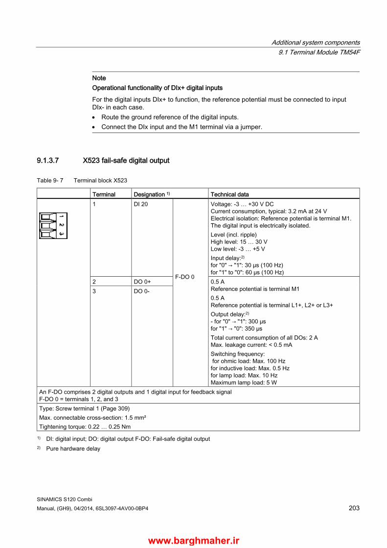
Additional system components 9.1 Terminal Module TM54F
SINAMICS S120 Combi Manual, (GH9), 04/2014, 6SL3097-4AV00-0BP4 203
Note Operational functionality of DIx+ digital inputs
For the digital inputs DIx+ to function, the reference potential must be connected to input DIx- in each case. • Route the ground reference of the digital inputs. • Connect the DIx input and the M1 terminal via a jumper.
9.1.3.7 X523 fail-safe digital output
Table 9- 7 Terminal block X523
Terminal Designation 1) Technical data
1 DI 20 F-DO 0
Voltage: -3 … +30 V DC Current consumption, typical: 3.2 mA at 24 V Electrical isolation: Reference potential is terminal M1. The digital input is electrically isolated. Level (incl. ripple) High level: 15 … 30 V Low level: -3 … +5 V Input delay:2) for "0" → "1": 30 μs (100 Hz) for "1" to "0": 60 μs (100 Hz)
2 DO 0+ 0.5 A Reference potential is terminal M1 0.5 A Reference potential is terminal L1+, L2+ or L3+ Output delay:2) - for "0" → "1": 300 μs for "1" → "0": 350 µs Total current consumption of all DOs: 2 A Max. leakage current: < 0.5 mA Switching frequency: for ohmic load: Max. 100 Hz for inductive load: Max. 0.5 Hz for lamp load: Max. 10 Hz Maximum lamp load: 5 W
3 DO 0-
An F-DO comprises 2 digital outputs and 1 digital input for feedback signal F-DO 0 = terminals 1, 2, and 3 Type: Screw terminal 1 (Page 309) Max. connectable cross-section: 1.5 mm² Tightening torque: 0.22 … 0.25 Nm 1) DI: digital input; DO: digital output F-DO: Fail-safe digital output
2) Pure hardware delay
www.barghmaher.ir

Additional system components 9.1 Terminal Module TM54F
SINAMICS S120 Combi 204 Manual, (GH9), 04/2014, 6SL3097-4AV00-0BP4
9.1.3.8 X524 Electronics power supply
Table 9- 8 Terminals for the electronics power supply
Terminal Designation Technical data
+ Electronics power supply Voltage: 24 V DC (20.4 ... 28.8 V) Current consumption: Max. 0.7 A Max. current via jumper in connector: 20 A (15 A according to UL/CSA)
+ Electronics power supply M Electronics ground M Electronics ground Type: Screw terminal 3 (Page 309)
Max. connectable cross-section: 2.5 mm² Tightening torque: 0.4 … 0.5 Nm
The maximum cable length that can be connected is 10 m.
Note
The two "+" and "M" terminals are jumpered in the connector. This ensures that the supply voltage is looped through. The current consumption increases by the value for the DRIVE-CLiQ node.
www.barghmaher.ir
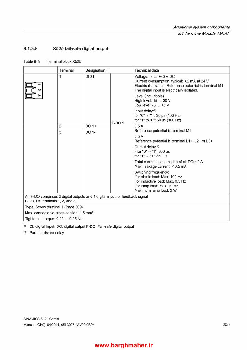
Additional system components 9.1 Terminal Module TM54F
SINAMICS S120 Combi Manual, (GH9), 04/2014, 6SL3097-4AV00-0BP4 205
9.1.3.9 X525 fail-safe digital output
Table 9- 9 Terminal block X525
Terminal Designation 1) Technical data
1 DI 21 F-DO 1
Voltage: -3 … +30 V DC Current consumption, typical: 3.2 mA at 24 V Electrical isolation: Reference potential is terminal M1 The digital input is electrically isolated. Level (incl. ripple) High level: 15 … 30 V Low level: -3 … +5 V Input delay:2) for "0" → "1": 30 μs (100 Hz) for "1" to "0": 60 μs (100 Hz)
2 DO 1+ 0.5 A Reference potential is terminal M1 0.5 A Reference potential is terminal L1+, L2+ or L3+ Output delay:2) - for "0" → "1": 300 μs for "1" → "0": 350 µs Total current consumption of all DOs: 2 A Max. leakage current: < 0.5 mA Switching frequency: for ohmic load: Max. 100 Hz for inductive load: Max. 0.5 Hz for lamp load: Max. 10 Hz Maximum lamp load: 5 W
3 DO 1-
An F-DO comprises 2 digital outputs and 1 digital input for feedback signal F-DO 1 = terminals 1, 2, and 3 Type: Screw terminal 1 (Page 309) Max. connectable cross-section: 1.5 mm² Tightening torque: 0.22 … 0.25 Nm 1) DI: digital input; DO: digital output F-DO: Fail-safe digital output
2) Pure hardware delay
www.barghmaher.ir

Additional system components 9.1 Terminal Module TM54F
SINAMICS S120 Combi 206 Manual, (GH9), 04/2014, 6SL3097-4AV00-0BP4
9.1.3.10 X531 fail-safe digital inputs + power supply with forced dormant error detection
Table 9- 10 Terminal block X531
Terminal Designation 1) Technical data
1 L 2+ Voltage: 24 V DC Max. total load current: 500 mA
2 DI 10 F-DI 5 Voltage: -3 … +30 V DC Current consumption, typical: 3.2 mA at 24 V Electrical isolation: Reference potential, refer to terminals 6, 7, 8 All digital inputs are electrically isolated. Level (incl. ripple) High level: 15 … 30 V Low level: -3 … +5 V Input delay:2) - for "0" → "1": 30 μs (100 Hz) - for "1" to "0": 60 μs (100 Hz)
3 DI 11+ 4 DI 12 F-DI 6 5 DI 13+
6 DI 11- F-DI 5 Reference potential to DI 11+ 7 DI 13- F-DI 6 Reference potential to DI 13+ 8 M1 Reference potential to DI 10, DI 12, L2+
An F-DI comprises a digital input and a 2nd digital input where, in addition, the cathode of the optocoupler is fed-out. F-DI 5 = terminals 2, 3 and 6 F-DI 6 = terminals 4, 5 and 7 Type: Screw terminal 1 (Page 309) Max. connectable cross-section: 1.5 mm² Tightening torque: 0.22 … 0.25 Nm 1) DI: Digital input, F-DI: Fail-safe digital input
2) Pure hardware delay
Note Operational functionality of DIx+ digital inputs
For the digital inputs DIx+ to function, the reference potential must be connected to input DIx- in each case. • Route the ground reference of the digital inputs. • Connect the DIx input and the M1 terminal via a jumper.
www.barghmaher.ir
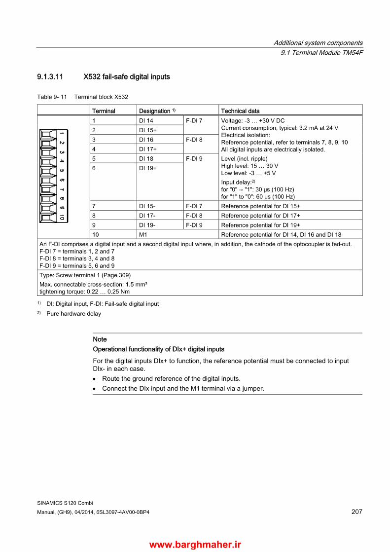
Additional system components 9.1 Terminal Module TM54F
SINAMICS S120 Combi Manual, (GH9), 04/2014, 6SL3097-4AV00-0BP4 207
9.1.3.11 X532 fail-safe digital inputs
Table 9- 11 Terminal block X532
Terminal Designation 1) Technical data
1 DI 14 F-DI 7 Voltage: -3 … +30 V DC Current consumption, typical: 3.2 mA at 24 V Electrical isolation: Reference potential, refer to terminals 7, 8, 9, 10 All digital inputs are electrically isolated. Level (incl. ripple) High level: 15 … 30 V Low level: -3 … +5 V Input delay:2) for "0" → "1": 30 μs (100 Hz) for "1" to "0": 60 μs (100 Hz)
2 DI 15+ 3 DI 16 F-DI 8 4 DI 17+ 5 DI 18 F-DI 9 6 DI 19+
7 DI 15- F-DI 7 Reference potential for DI 15+ 8 DI 17- F-DI 8 Reference potential for DI 17+ 9 DI 19- F-DI 9 Reference potential for DI 19+ 10 M1 Reference potential for DI 14, DI 16 and DI 18
An F-DI comprises a digital input and a second digital input where, in addition, the cathode of the optocoupler is fed-out. F-DI 7 = terminals 1, 2 and 7 F-DI 8 = terminals 3, 4 and 8 F-DI 9 = terminals 5, 6 and 9 Type: Screw terminal 1 (Page 309) Max. connectable cross-section: 1.5 mm² tightening torque: 0.22 … 0.25 Nm 1) DI: Digital input, F-DI: Fail-safe digital input
2) Pure hardware delay
Note Operational functionality of DIx+ digital inputs
For the digital inputs DIx+ to function, the reference potential must be connected to input DIx- in each case. • Route the ground reference of the digital inputs. • Connect the DIx input and the M1 terminal via a jumper.
www.barghmaher.ir
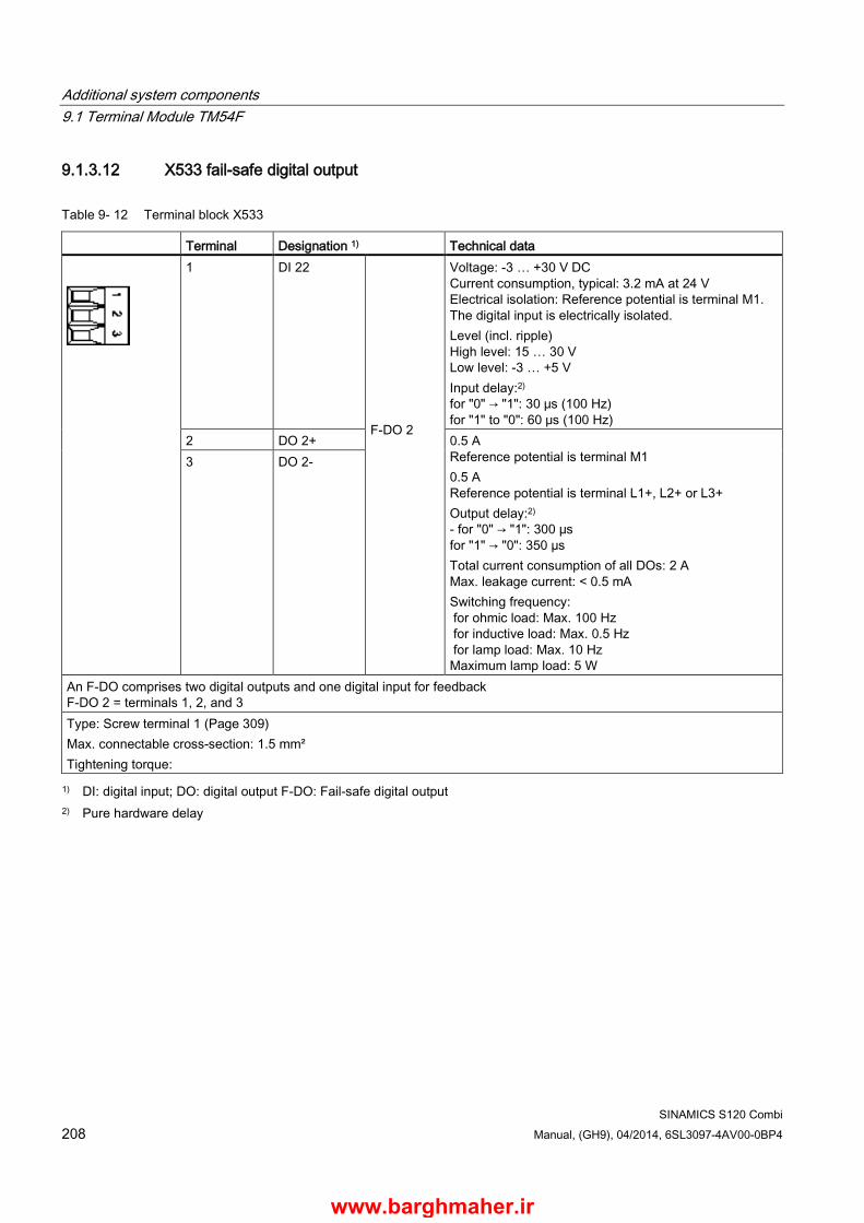
Additional system components 9.1 Terminal Module TM54F
SINAMICS S120 Combi 208 Manual, (GH9), 04/2014, 6SL3097-4AV00-0BP4
9.1.3.12 X533 fail-safe digital output
Table 9- 12 Terminal block X533
Terminal Designation 1) Technical data
1 DI 22 F-DO 2
Voltage: -3 … +30 V DC Current consumption, typical: 3.2 mA at 24 V Electrical isolation: Reference potential is terminal M1. The digital input is electrically isolated. Level (incl. ripple) High level: 15 … 30 V Low level: -3 … +5 V Input delay:2) for "0" → "1": 30 μs (100 Hz) for "1" to "0": 60 μs (100 Hz)
2 DO 2+ 0.5 A Reference potential is terminal M1 0.5 A Reference potential is terminal L1+, L2+ or L3+ Output delay:2) - for "0" → "1": 300 μs for "1" → "0": 350 µs Total current consumption of all DOs: 2 A Max. leakage current: < 0.5 mA Switching frequency: for ohmic load: Max. 100 Hz for inductive load: Max. 0.5 Hz for lamp load: Max. 10 Hz Maximum lamp load: 5 W
3 DO 2-
An F-DO comprises two digital outputs and one digital input for feedback F-DO 2 = terminals 1, 2, and 3 Type: Screw terminal 1 (Page 309) Max. connectable cross-section: 1.5 mm² Tightening torque: 1) DI: digital input; DO: digital output F-DO: Fail-safe digital output
2) Pure hardware delay
www.barghmaher.ir

Additional system components 9.1 Terminal Module TM54F
SINAMICS S120 Combi Manual, (GH9), 04/2014, 6SL3097-4AV00-0BP4 209
9.1.3.13 X535 fail-safe digital output
Table 9- 13 Terminal block X535
Terminal Designation 1) Technical data
1 DI 23 F-DO 3
Voltage: -3 … +30 V DC Current consumption, typical: 3.2 mA at 24 V Electrical isolation: Reference potential is terminal M1. The digital input is electrically isolated. Level (incl. ripple) High level: 15 … 30 V Low level: -3 … +5 V Input delay:2) for "0" → "1": 30 μs (100 Hz) for "1" to "0": 60 μs (100 Hz)
2 DO 3+ 0.5 A Reference potential is terminal M1 0.5 A Reference potential is terminal L1+, L2+ or L3+ Output delay:2) - for "0" → "1": 300 μs for "1" → "0": 350 µs Total current consumption of all DOs: 2 A Max. leakage current: < 0.5 mA Switching frequency: for ohmic load: Max. 100 Hz for inductive load: Max. 0.5 Hz for lamp load: Max. 10 Hz Maximum lamp load: 5 W
3 DO 3-
An F-DO comprises 2 digital outputs and 1 digital input for feedback signal F-DO 3 = terminals 1, 2, and 3 Type: Screw terminal 1 (Page 309) Max. connectable cross-section: 1.5 mm² Tightening torque: 0.22 … 0.25 Nm 1) DI: digital input; DO: digital output F-DO: Fail-safe digital output
2) Pure hardware delay
www.barghmaher.ir
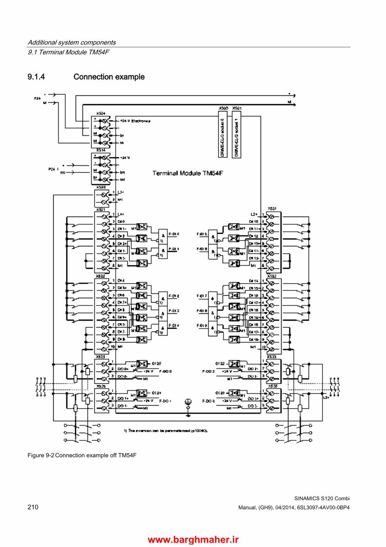
Additional system components 9.1 Terminal Module TM54F
SINAMICS S120 Combi 210 Manual, (GH9), 04/2014, 6SL3097-4AV00-0BP4
9.1.4 Connection example
Figure 9-2 Connection example off TM54F
www.barghmaher.ir
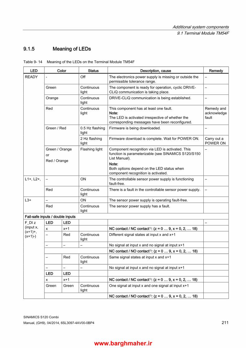
Additional system components 9.1 Terminal Module TM54F
SINAMICS S120 Combi Manual, (GH9), 04/2014, 6SL3097-4AV00-0BP4 211
9.1.5 Meaning of LEDs
Table 9- 14 Meaning of the LEDs on the Terminal Module TM54F
LED Color Status Description, cause Remedy READY - Off The electronics power supply is missing or outside the
permissible tolerance range. –
Green Continuous light
The component is ready for operation, cyclic DRIVE-CLiQ communication is taking place.
–
Orange Continuous light
DRIVE-CLiQ communication is being established. –
Red Continuous light
This component has at least one fault. Note: The LED is activated irrespective of whether the corresponding messages have been reconfigured.
Remedy and acknowledge fault
Green / Red 0.5 Hz flashing light
Firmware is being downloaded. –
2 Hz flashing light
Firmware download is complete. Wait for POWER ON. Carry out a POWER ON
Green / Orange or Red / Orange
Flashing light Component recognition via LED is activated. This function is parameterizable (see SINAMICS S120/S150 List Manual). Note: Both options depend on the LED status when component recognition is activated.
–
L1+, L2+, – ON The controllable sensor power supply is functioning fault-free.
–
Red Continuous light
There is a fault in the controllable sensor power supply. –
L3+ – ON The sensor power supply is operating fault-free. Red Continuous
light The sensor power supply has a fault.
Fail-safe inputs / double inputs F_DI z (input x, (x+1)+, (x+1)-)
LED LED – x x+1 NC contact / NC contact1): (z = 0 … 9, x = 0, 2, … 18) – Red Continuous
light Different signal states at input x and x+1
– – – No signal at input x and no signal at input x+1 NC contact / NO contact1): (z = 0 … 9, x = 0, 2, … 18) – Red Continuous
light Same signal states at input x and x+1
– – – No signal at input x and no signal at input x+1 LED LED x x+1 NC contact / NC contact1): (z = 0 … 9, x = 0, 2, … 18) Green Green Continuous
light One signal at input x and one signal at input x+1
NC contact / NO contact1): (z = 0 … 9, x = 0, 2, … 18)
www.barghmaher.ir

Additional system components 9.1 Terminal Module TM54F
SINAMICS S120 Combi 212 Manual, (GH9), 04/2014, 6SL3097-4AV00-0BP4
LED Color Status Description, cause Remedy Green Green Continuous
light One signal at input x and no signal at input x+1 –
Single digital inputs, not fail-safe DI x
– Off No signal at digital input x (x = 20 ... 23) – Green Continuous
light Signal at digital input x –
Fail-safe digital outputs with associated readback channel F_DO y (0+..3+, 0-..3-)
Green Continuous light
Output y (y = 0 … 3) has an active signal –
Readback input DI 2y for output F_DO y (y = 0 ... 3) for test stop. The status of the LEDs also depends on the type of external circuit. DI 2y – Off One of the two output lines y+ or y- or both lines of
output y carry a signal –
Green Continuous light
Both output lines y+ and y- carry no signal –
1) Inputs x+1 (DI 1+, 3+, .. 19+) can be individually adjusted using a parameter (see SINAMICS S120/S150 List Manual)
Cause and rectification of faults The following reference contains information about the cause of faults and how they can be rectified:
SINAMICS S120 Commissioning Manual (IH1)
SINAMICS S120/S150, List Manual (LH1)
www.barghmaher.ir

Additional system components 9.1 Terminal Module TM54F
SINAMICS S120 Combi Manual, (GH9), 04/2014, 6SL3097-4AV00-0BP4 213
9.1.6 Dimension drawing
Figure 9-3 Dimension drawing of Terminal Module TM54F, all data in mm and (inches)
www.barghmaher.ir

Additional system components 9.1 Terminal Module TM54F
SINAMICS S120 Combi 214 Manual, (GH9), 04/2014, 6SL3097-4AV00-0BP4
9.1.7 Installation
Installation 1. Tilt the component backwards slightly and attach it to the DIN rail using the hooks.
2. Swivel the component onto the DIN rail until you hear the mounting slide at the rear latch into position.
3. Slide the components along the mounting rail to either the left or right up to their final position.
Removal 1. First shift the mounting slide downwards at the lug to release the interlocking with the
mounting rail.
2. Swivel the component to the front and withdraw it upwards from the DIN rail.
① ②
Mounting slide Mounting rail
Figure 9-4 Removing from a DIN mounting rail
www.barghmaher.ir

Additional system components 9.1 Terminal Module TM54F
SINAMICS S120 Combi Manual, (GH9), 04/2014, 6SL3097-4AV00-0BP4 215
9.1.8 Protective conductor connection and shield support It is always advisable to shield the digital input and output wiring.
The following diagram shows a typical Weidmüller shield connection clamp for the shield supports.
① Protective conductor connection M4 / 1.8 Nm ② Shield connection terminal, Weidmüller company, type: KLBÜ CO1, order number:
1753311001
Figure 9-5 Shield support and protective conductor connection
NOTICE
Damage or faulty operation due to incorrect shielding or inadmissible cable lengths
If the correct shielding procedures or the permissible cable lengths are not observed, it can cause damage or the machine may malfunction. • Only use shielded cables. • Do not exceed the cable lengths stated in the technical data.
www.barghmaher.ir
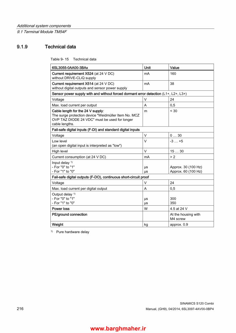
Additional system components 9.1 Terminal Module TM54F
SINAMICS S120 Combi 216 Manual, (GH9), 04/2014, 6SL3097-4AV00-0BP4
9.1.9 Technical data
Table 9- 15 Technical data
6SL3055-0AA00-3BAx Unit Value Current requirement X524 (at 24 V DC) without DRIVE-CLiQ supply
mA 160
Current requirement X514 (at 24 V DC) without digital outputs and sensor power supply
mA 38
Sensor power supply with and without forced dormant error detection (L1+, L2+, L3+) Voltage V 24 Max. load current per output A 0,5 Cable length for the 24 V supply: The surge protection device "Weidmüller Item No. MCZ OVP TAZ DIODE 24 VDC" must be used for longer cable lengths.
m < 30
Fail-safe digital inputs (F-DI) and standard digital inputs Voltage V 0 … 30 Low level (an open digital input is interpreted as "low")
V -3 … +5
High level V 15 … 30 Current consumption (at 24 V DC) mA > 2 Input delay 1) - For "0" to "1" - For "1" to "0"
μs μs
Approx. 30 (100 Hz) Approx. 60 (100 Hz)
Fail-safe digital outputs (F-DO), continuous short-circuit proof Voltage V 24 Max. load current per digital output A 0,5 Output delay 1) - For "0" to "1" - For "1" to "0"
μs μs
300 350
Power loss W 4.5 at 24 V PE/ground connection At the housing with
M4 screw Weight kg approx. 0.9 1) Pure hardware delay
www.barghmaher.ir
Additional system components 9.2 DRIVE-CLiQ hub Module DMC20
SINAMICS S120 Combi Manual, (GH9), 04/2014, 6SL3097-4AV00-0BP4 217
9.2 DRIVE-CLiQ Hub Module DMC20
9.2.1 Description The DRIVE-CLiQ Hub Module DMC20 is a DRIVE-CLiQ component and can be snapped onto a standard mounting rail (EN 60715). It is only used to connect direct measuring systems for the feed axes and expansion axes of the S120 Combi.
Note
The DMC20 should also be used if only one feed axis is coupled with a direct measuring system.
A fixed topology applies when assigning the particular feed axis to a DRIVE-CLiQ interface (see Section Topology rules for DRIVE-CLiQ (Page 127)) and this must be observed.
9.2.2 Safety information
WARNING
Danger to life if the fundamental safety instructions and remaining risks are not carefully observed
If the fundamental safety instructions and remaining risks in Chapter 1 (Page 19) are not observed, accidents involving severe injuries or death may occur. • Adhere to the fundamental safety instructions. • When assessing the risk, take into account residual risks.
WARNING
Fire hazard due to overheating because of inadequate ventilation clearances
Inadequate ventilation clearances can cause overheating with a risk for personnel due to smoke and fire. This can also result in increased failure rates and a shorter service life for Hub Modules. • It is absolutely essential that you maintain ventilation clearances according to the table
Ventilation clearances above and below the component (Page 312).
www.barghmaher.ir
Additional system components 9.2 DRIVE-CLiQ Hub Module DMC20
SINAMICS S120 Combi 218 Manual, (GH9), 04/2014, 6SL3097-4AV00-0BP4
Note
All components operated on the DRIVE-CLiQ must be integrated into the equipotential bonding concept. They should preferably be connected by installing them on bare metal machine parts and devices, which are all bonded to one another in an equipotential manner. Alternatively, equipotential bonding can be achieved by means of a conductor (min. 6 mm²), which should be routed parallel to the DRIVE-CLiQ where possible. This involves all distributed DRIVE-CLiQ participants.
www.barghmaher.ir
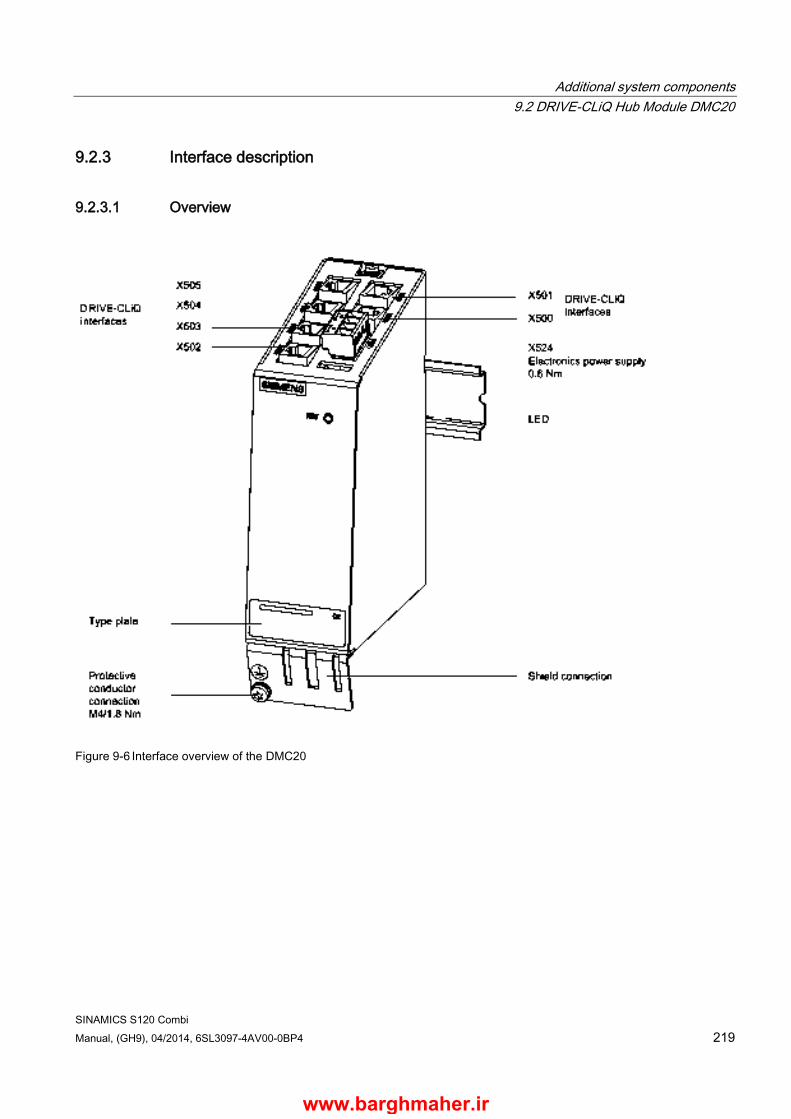
Additional system components 9.2 DRIVE-CLiQ Hub Module DMC20
SINAMICS S120 Combi Manual, (GH9), 04/2014, 6SL3097-4AV00-0BP4 219
9.2.3 Interface description
9.2.3.1 Overview
Figure 9-6 Interface overview of the DMC20
www.barghmaher.ir
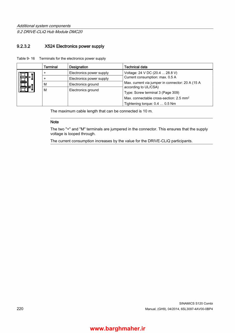
Additional system components 9.2 DRIVE-CLiQ Hub Module DMC20
SINAMICS S120 Combi 220 Manual, (GH9), 04/2014, 6SL3097-4AV00-0BP4
9.2.3.2 X524 Electronics power supply
Table 9- 16 Terminals for the electronics power supply
Terminal Designation Technical data
+ Electronics power supply Voltage: 24 V DC (20.4 ... 28.8 V) Current consumption: max. 0.5 A Max. current via jumper in connector: 20 A (15 A according to UL/CSA) Type: Screw terminal 3 (Page 309) Max. connectable cross-section: 2.5 mm2 Tightening torque: 0.4 … 0.5 Nm
+ Electronics power supply M Electronics ground M Electronics ground
The maximum cable length that can be connected is 10 m.
Note
The two "+" and "M" terminals are jumpered in the connector. This ensures that the supply voltage is looped through.
The current consumption increases by the value for the DRIVE-CLiQ participants.
www.barghmaher.ir
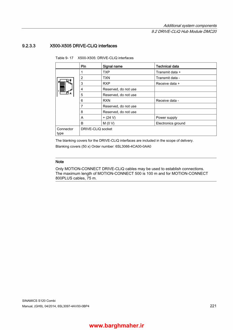
Additional system components 9.2 DRIVE-CLiQ Hub Module DMC20
SINAMICS S120 Combi Manual, (GH9), 04/2014, 6SL3097-4AV00-0BP4 221
9.2.3.3 X500-X505 DRIVE-CLiQ interfaces
Table 9- 17 X500-X505: DRIVE-CLiQ interfaces
Pin Signal name Technical data
1 TXP Transmit data + 2 TXN Transmit data - 3 RXP Receive data + 4 Reserved, do not use 5 Reserved, do not use 6 RXN Receive data - 7 Reserved, do not use 8 Reserved, do not use A + (24 V) Power supply B M (0 V) Electronics ground
Connector type
DRIVE-CLiQ socket
The blanking covers for the DRIVE-CLiQ interfaces are included in the scope of delivery. Blanking covers (50 x) Order number: 6SL3066-4CA00-0AA0
Note
Only MOTION-CONNECT DRIVE-CLiQ cables may be used to establish connections. The maximum length of MOTION-CONNECT 500 is 100 m and for MOTION-CONNECT 800PLUS cables, 75 m.
www.barghmaher.ir

Additional system components 9.2 DRIVE-CLiQ Hub Module DMC20
SINAMICS S120 Combi 222 Manual, (GH9), 04/2014, 6SL3097-4AV00-0BP4
9.2.3.4 Meaning of the LED on the DMC20
Table 9- 18 Meaning of the LED on the DMC20
LED Color Status Description READY - Off The electronics power supply is missing or outside the permissible
tolerance range. Green Continuous light The component is ready for operation and cyclic DRIVE-CLiQ
communication is taking place. Orange Continuous light DRIVE-CLiQ communication is being established. Red Continuous light This component has at least one fault.
Note: The LED is activated irrespective of whether the corresponding messages have been reconfigured.
Green / Red 0.5 Hz flashing light
Firmware is being downloaded.
2 Hz flashing light
Firmware download is complete. Wait for POWER ON
Green / Orange or Red / Orange
Flashing light Component recognition via LED is activated. This function is parameterizable (see SINAMICS S120/S150 List Manual). Note: Both options depend on the LED status when component recognition is activated.
Cause and rectification of faults
The following reference contains information about the cause of faults and how they can be rectified:
SINAMICS S120 Commissioning Manual (IH1)
SINAMICS S120/S150, List Manual (LH1)
www.barghmaher.ir

Additional system components 9.2 DRIVE-CLiQ Hub Module DMC20
SINAMICS S120 Combi Manual, (GH9), 04/2014, 6SL3097-4AV00-0BP4 223
9.2.4 Dimension drawing
Figure 9-7 Dimension drawing of the DRIVE-CLiQ Hub Module DMC20, all data in mm and (inches)
www.barghmaher.ir

Additional system components 9.2 DRIVE-CLiQ Hub Module DMC20
SINAMICS S120 Combi 224 Manual, (GH9), 04/2014, 6SL3097-4AV00-0BP4
9.2.5 Installation
Installation 1. Tilt the component backwards slightly and attach it to the DIN rail using the hooks.
2. Swivel the component onto the DIN rail until you hear the mounting slide at the rear latch into position.
3. Slide the components along the mounting rail to either the left or right up to their final position.
Removal 1. First shift the mounting slide downwards at the lug to release the interlocking with the
mounting rail.
2. Swivel the component to the front and withdraw it upwards from the DIN rail.
① Mounting slide ② Mounting rail Figure 9-8 Removing from a DIN mounting rail
www.barghmaher.ir
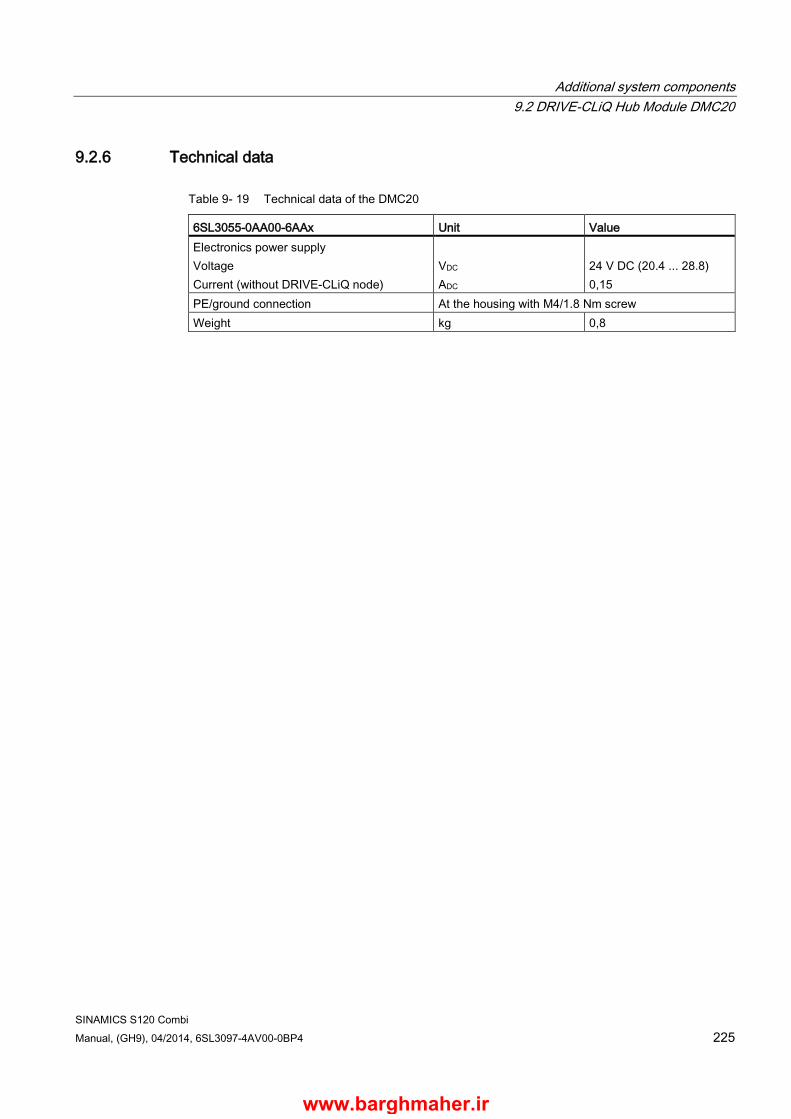
Additional system components 9.2 DRIVE-CLiQ Hub Module DMC20
SINAMICS S120 Combi Manual, (GH9), 04/2014, 6SL3097-4AV00-0BP4 225
9.2.6 Technical data
Table 9- 19 Technical data of the DMC20
6SL3055-0AA00-6AAx Unit Value Electronics power supply Voltage Current (without DRIVE-CLiQ node)
VDC ADC
24 V DC (20.4 ... 28.8) 0,15
PE/ground connection At the housing with M4/1.8 Nm screw Weight kg 0,8
www.barghmaher.ir
Additional system components 9.3 DRIVE-CLiQ Hub Module External DME20
SINAMICS S120 Combi 226 Manual, (GH9), 04/2014, 6SL3097-4AV00-0BP4
9.3 DRIVE-CLiQ Hub Module External DME20
9.3.1 Description The DRIVE-CLiQ Hub Module External DME20, just like the DRIVE-CLiQ Hub Module DMC20, is only used to connect direct measuring systems for the feed axes and expansion axes of the S120 Combi.
The component has degree of protection IP67.
Note
The DME20 should also be used if only one feed axis is coupled with a direct measuring system.
A fixed topology applies when assigning the particular feed axis to a DRIVE-CLiQ interface (see Section Topology rules for DRIVE-CLiQ (Page 127)) and this must be observed.
9.3.2 Safety information
WARNING
Danger to life if the fundamental safety instructions and remaining risks are not carefully observed
If the fundamental safety instructions and remaining risks in Chapter 1 (Page 19) are not observed, accidents involving severe injuries or death may occur. • Adhere to the fundamental safety instructions. • When assessing the risk, take into account residual risks.
NOTICE
Damage due to leaking plug connections
If IP67 protection is not ensured, water or dirt can enter and lead to material damage. • All plug connectors must be correctly screwed into place and appropriately locked.
Note Malfunctions due to polluted DRIVE-CLiQ interfaces
Malfunctions can occur in the system through the use of polluted DRIVE-CLiQ interfaces. • Cover unused DRIVE-CLiQ interfaces with the supplied blanking covers.
www.barghmaher.ir

Additional system components 9.3 DRIVE-CLiQ Hub Module External DME20
SINAMICS S120 Combi Manual, (GH9), 04/2014, 6SL3097-4AV00-0BP4 227
Note
All components operated on the DRIVE-CLiQ must be integrated into the equipotential bonding concept. They should preferably be connected by installing them on bare metal machine parts and devices, which are all bonded to one another in an equipotential manner. Alternatively, equipotential bonding can be achieved by means of a conductor (min. 6 mm²), which should be routed parallel to the DRIVE-CLiQ where possible. This applies to all distributed DRIVE-CLiQ participants. For the DME20 this also applies to the 24 V power supply.
9.3.3 Interface description
9.3.3.1 Overview
Figure 9-9 Interface overview of the DME20
www.barghmaher.ir
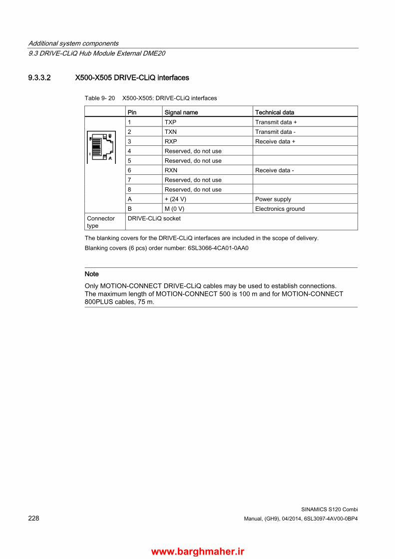
Additional system components 9.3 DRIVE-CLiQ Hub Module External DME20
SINAMICS S120 Combi 228 Manual, (GH9), 04/2014, 6SL3097-4AV00-0BP4
9.3.3.2 X500-X505 DRIVE-CLiQ interfaces
Table 9- 20 X500-X505: DRIVE-CLiQ interfaces
Pin Signal name Technical data
1 TXP Transmit data + 2 TXN Transmit data - 3 RXP Receive data + 4 Reserved, do not use 5 Reserved, do not use 6 RXN Receive data - 7 Reserved, do not use 8 Reserved, do not use A + (24 V) Power supply B M (0 V) Electronics ground
Connector type
DRIVE-CLiQ socket
The blanking covers for the DRIVE-CLiQ interfaces are included in the scope of delivery. Blanking covers (6 pcs) order number: 6SL3066-4CA01-0AA0
Note
Only MOTION-CONNECT DRIVE-CLiQ cables may be used to establish connections. The maximum length of MOTION-CONNECT 500 is 100 m and for MOTION-CONNECT 800PLUS cables, 75 m.
www.barghmaher.ir
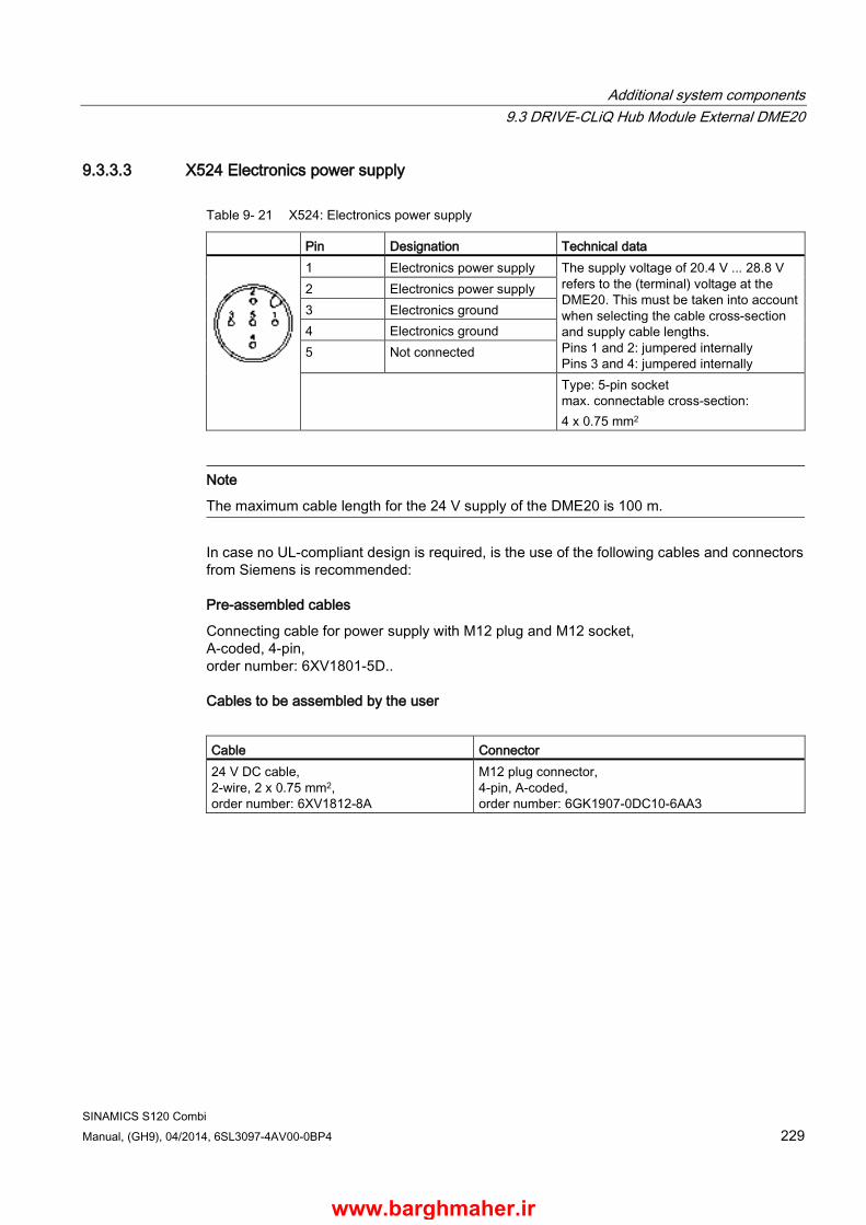
Additional system components 9.3 DRIVE-CLiQ Hub Module External DME20
SINAMICS S120 Combi Manual, (GH9), 04/2014, 6SL3097-4AV00-0BP4 229
9.3.3.3 X524 Electronics power supply
Table 9- 21 X524: Electronics power supply
Pin Designation Technical data
1 Electronics power supply The supply voltage of 20.4 V ... 28.8 V refers to the (terminal) voltage at the DME20. This must be taken into account when selecting the cable cross-section and supply cable lengths. Pins 1 and 2: jumpered internally Pins 3 and 4: jumpered internally
2 Electronics power supply 3 Electronics ground 4 Electronics ground 5 Not connected
Type: 5-pin socket max. connectable cross-section: 4 x 0.75 mm2
Note
The maximum cable length for the 24 V supply of the DME20 is 100 m.
In case no UL-compliant design is required, is the use of the following cables and connectors from Siemens is recommended:
Pre-assembled cables
Connecting cable for power supply with M12 plug and M12 socket, A-coded, 4-pin, order number: 6XV1801-5D..
Cables to be assembled by the user
Cable Connector 24 V DC cable, 2-wire, 2 x 0.75 mm2, order number: 6XV1812-8A
M12 plug connector, 4-pin, A-coded, order number: 6GK1907-0DC10-6AA3
www.barghmaher.ir

Additional system components 9.3 DRIVE-CLiQ Hub Module External DME20
SINAMICS S120 Combi 230 Manual, (GH9), 04/2014, 6SL3097-4AV00-0BP4
Table 9- 22 Cable length P24 supply cable
Connected loads 1)m
1 2 3 4 5
Cross-section 0.34 mm² 75 m 45 m 30 m 25 m 20 m 2 x 0.34 mm² 100 m 90 m 65 m 50 m 40 m 0.75 mm² 100 m 100 m 75 m 60 m 50 m 2 x 0.75 mm² 100 m 100 m 100 m 100 m 100 m Ta = 55 °C 100 m DRIVE-CLiQ 1) Connected motors with DRIVE-CLiQ encoder, DRIVE CLiQ mounted encoder SME
www.barghmaher.ir
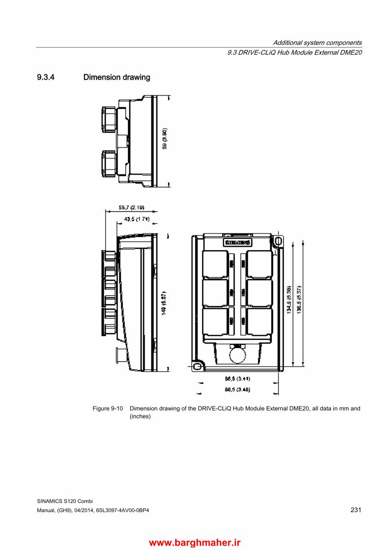
Additional system components 9.3 DRIVE-CLiQ Hub Module External DME20
SINAMICS S120 Combi Manual, (GH9), 04/2014, 6SL3097-4AV00-0BP4 231
9.3.4 Dimension drawing
Figure 9-10 Dimension drawing of the DRIVE-CLiQ Hub Module External DME20, all data in mm and
(inches)
www.barghmaher.ir
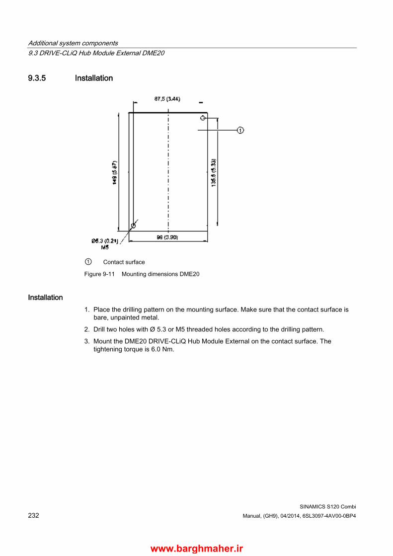
Additional system components 9.3 DRIVE-CLiQ Hub Module External DME20
SINAMICS S120 Combi 232 Manual, (GH9), 04/2014, 6SL3097-4AV00-0BP4
9.3.5 Installation
① Contact surface
Figure 9-11 Mounting dimensions DME20
Installation 1. Place the drilling pattern on the mounting surface. Make sure that the contact surface is
bare, unpainted metal.
2. Drill two holes with Ø 5.3 or M5 threaded holes according to the drilling pattern.
3. Mount the DME20 DRIVE-CLiQ Hub Module External on the contact surface. The tightening torque is 6.0 Nm.
www.barghmaher.ir

Additional system components 9.3 DRIVE-CLiQ Hub Module External DME20
SINAMICS S120 Combi Manual, (GH9), 04/2014, 6SL3097-4AV00-0BP4 233
9.3.6 Technical data
Table 9- 23 Technical data of the DME20
6SL3055-0AA00-6ABx Unit Value Electronics power supply Voltage Current (without DRIVE-CLiQ node)
VDC ADC
24 (20,4 … 28,8) 0,15
PE/ground connection Screwed to the housing M5 / 6 Nm Degree of protection IP67 Weight kg 0,8
9.3.7 Specifications for use with UL approval
Pre-assembled cables
Sensor/actuator cable, 5-pin, variable cable, free cable end at straight socket M12-SPEEDCON, cable length: 2, 5, 10, 15 m SAC-5P-xxx-186/FS SCO Up to 100 m on request
Phoenix Contact
Cables to be assembled by the user
Cable Connector Cable coil, black PUR/PVC, 5-pin Conductor colors: brown/white/blue/black/gray Cable length: 100 m SAC-5P-100.0-186/0.75 Order number: 1535590
Sensor/actuator connector, socket, straight, 5-pin, M12, A-coded Screw connection, metal knurl, cable gland Pg9 SACC-M12FS-5CON-PG9-M Order number: 1681486
Phoenix Contact
Power supply
The DME20 must use one of the following 24 V power supplies with voltage limiting:
● SITOP 6EP1x.. or 6ES7307..
● SINAMICS Control Supply Module 6SL3100-1DE22-0Axx
www.barghmaher.ir

Additional system components 9.3 DRIVE-CLiQ Hub Module External DME20
SINAMICS S120 Combi 234 Manual, (GH9), 04/2014, 6SL3097-4AV00-0BP4
Pin assignment of the cable
Table 9- 24 Connection to X524 electronics power supply
Pin Designation Technical data
1 (brown)1) Electronics power supply The supply voltage of 20.4 V ... 28.8 V refers to the (terminal) voltage at the DME20. This must be taken into account when selecting the cable cross-section and supply cable lengths. Pins 1 and 2: jumpered internally Pins 3 and 4: jumpered internally
2 (white) 1) Electronics power supply 3 (black) 1) Electronics ground 4 (blue) 1) Electronics ground 5 (gray) 1) Not connected internally
1) The colors refer to the cable specified above
www.barghmaher.ir
SINAMICS S120 Combi Manual, (GH9), 04/2014, 6SL3097-4AV00-0BP4 235
Encoder system connection 10 10.1 Sensor Module Cabinet-Mounted SMC20
10.1.1 Description The Sensor Module Cabinet-Mounted SMC20 evaluates encoder signals and transmits the speed, actual position value, rotor position and, if necessary, the motor temperature and reference point via DRIVE-CLiQ to the S120 Combi.
The SMC20 is used to evaluate encoder signals from incremental encoders with SIN/COS (1 Vpp) or absolute encoders with EnDat 2.1 or SSI.
10.1.2 Product-specific safety instructions
WARNING
Danger to life if the fundamental safety instructions and remaining risks are not carefully observed
If the fundamental safety instructions and remaining risks in Chapter 1 (Page 19) are not observed, accidents involving severe injuries or death may occur. • Adhere to the fundamental safety instructions. • When assessing the risk, take into account residual risks.
WARNING
Fire hazard due to overheating because of inadequate ventilation clearances
Inadequate ventilation clearances can cause overheating with a risk for personnel due to smoke and fire. This can also result in increased failure rates and a shorter service life for Sensor Modules. • Maintaining 50 mm ventilation clearances above and below the component is essential.
NOTICE
Damage when connecting an impermissible number of encoder systems
If more than the maximum permissible number of encoder systems are connected to a Sensor Module, this will cause damage. • At a Sensor Module only connect the maximum permissible number of encoder
systems.
www.barghmaher.ir

Encoder system connection 10.1 Sensor Module Cabinet-Mounted SMC20
SINAMICS S120 Combi 236 Manual, (GH9), 04/2014, 6SL3097-4AV00-0BP4
Note Diminished level of interference immunity due to equalizing currents via the electronics ground
Make sure there is no electrical connection between the encoder system housing and the signal lines and the sensor system electronics.
If this is not carefully observed, under certain circumstances the system will not be able to reach the required interference immunity level (there is then a danger of equalization currents flowing through the electronics ground).
www.barghmaher.ir

Encoder system connection 10.1 Sensor Module Cabinet-Mounted SMC20
SINAMICS S120 Combi Manual, (GH9), 04/2014, 6SL3097-4AV00-0BP4 237
10.1.3 Interface description
10.1.3.1 Overview
Figure 10-1 Interface description of the SMC20
www.barghmaher.ir
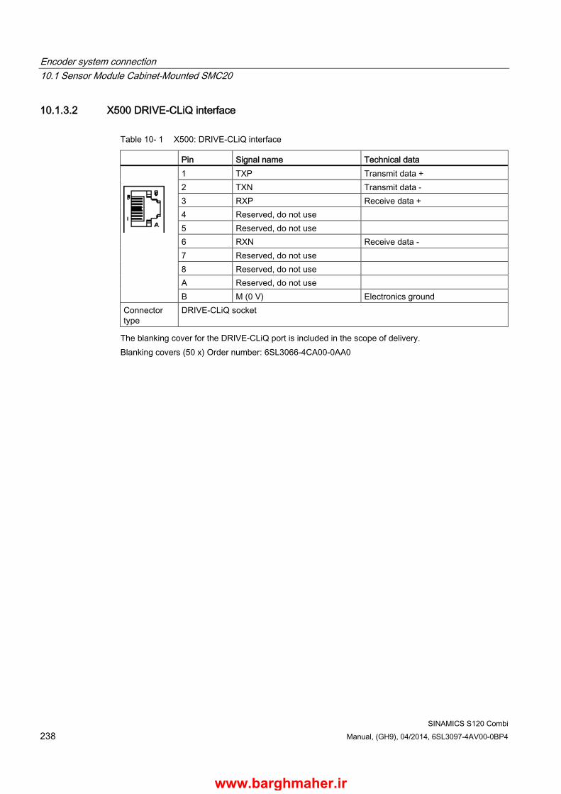
Encoder system connection 10.1 Sensor Module Cabinet-Mounted SMC20
SINAMICS S120 Combi 238 Manual, (GH9), 04/2014, 6SL3097-4AV00-0BP4
10.1.3.2 X500 DRIVE-CLiQ interface
Table 10- 1 X500: DRIVE-CLiQ interface
Pin Signal name Technical data
1 TXP Transmit data + 2 TXN Transmit data - 3 RXP Receive data + 4 Reserved, do not use 5 Reserved, do not use 6 RXN Receive data - 7 Reserved, do not use 8 Reserved, do not use A Reserved, do not use B M (0 V) Electronics ground
Connector type
DRIVE-CLiQ socket
The blanking cover for the DRIVE-CLiQ port is included in the scope of delivery. Blanking covers (50 x) Order number: 6SL3066-4CA00-0AA0
www.barghmaher.ir

Encoder system connection 10.1 Sensor Module Cabinet-Mounted SMC20
SINAMICS S120 Combi Manual, (GH9), 04/2014, 6SL3097-4AV00-0BP4 239
10.1.3.3 X520 encoder system interface
Table 10- 2 X520: Encoder system interface
Pin Signal name Technical data
1 P encoder Encoder power supply 2 M encoder Ground for encoder power supply 3 A Incremental signal A 4 A* Inverse incremental signal A 5 Ground Ground (for internal shield) 6 B Incremental signal B 7 B* Inverse incremental signal B 8 Ground Ground (for internal shield) 9 Reserved, do not use 10 Clock Clock, EnDat interface, SSI clock 11 Reserved, do not use 12 Clock*
Inverted clock, EnDat interface, inverted SSI clock
13 +Temp1) Motor temperature sensing KTY84-1C130 (KTY+) Temperature sensor KTY84-1C130 / PTC
14 P sense Sense input of encoder power supply 15 Data Data, EnDat interface,
SSI data 16 M sense Ground sense input encoder power supply 17 R Reference signal R 18 R* Inverse reference signal R 19 C Absolute track signal C 20 C* Inverse absolute track signal C 21 D Absolute track signal D 22 D* Inverse absolute track signal D 23 Data* Inverse data, EnDat interface,
Inverse SSI data 24 Ground Ground (for internal shield) 25 -Temp1) Motor temperature sensing KTY84-1C130 (KTY-)
Temperature sensor KTY84-1C130 / PTC Connector type: 25-pin SUB D connector Measuring current via temperature sensor connection: 2 mA 1) Accuracy of the temperature measurement:
- KTY: ±7°C (including evaluation) - PTC: ±5℃ (including evaluation)
www.barghmaher.ir
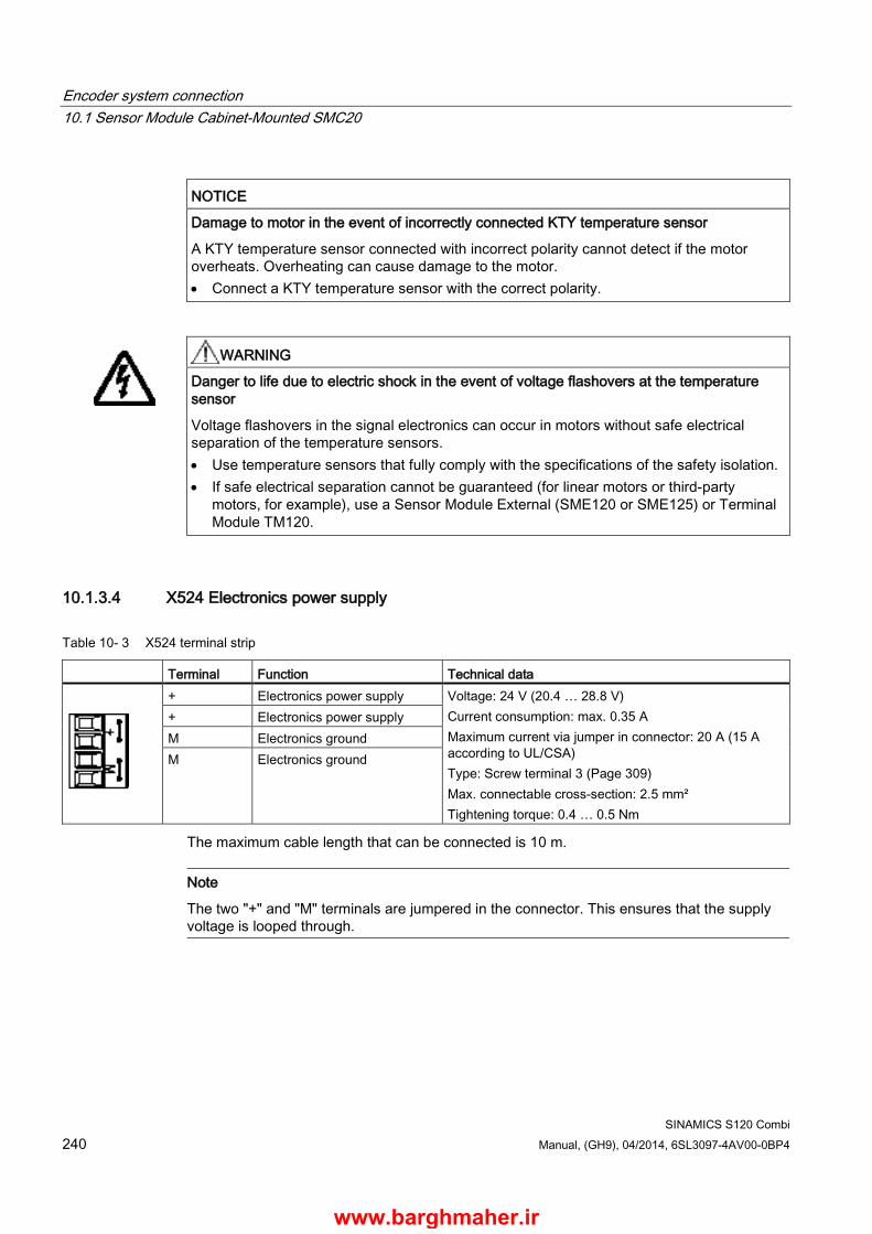
Encoder system connection 10.1 Sensor Module Cabinet-Mounted SMC20
SINAMICS S120 Combi 240 Manual, (GH9), 04/2014, 6SL3097-4AV00-0BP4
NOTICE
Damage to motor in the event of incorrectly connected KTY temperature sensor
A KTY temperature sensor connected with incorrect polarity cannot detect if the motor overheats. Overheating can cause damage to the motor. • Connect a KTY temperature sensor with the correct polarity.
WARNING
Danger to life due to electric shock in the event of voltage flashovers at the temperature sensor
Voltage flashovers in the signal electronics can occur in motors without safe electrical separation of the temperature sensors. • Use temperature sensors that fully comply with the specifications of the safety isolation. • If safe electrical separation cannot be guaranteed (for linear motors or third-party
motors, for example), use a Sensor Module External (SME120 or SME125) or Terminal Module TM120.
10.1.3.4 X524 Electronics power supply
Table 10- 3 X524 terminal strip
Terminal Function Technical data
+ Electronics power supply Voltage: 24 V (20.4 … 28.8 V) Current consumption: max. 0.35 A Maximum current via jumper in connector: 20 A (15 A according to UL/CSA) Type: Screw terminal 3 (Page 309) Max. connectable cross-section: 2.5 mm² Tightening torque: 0.4 … 0.5 Nm
+ Electronics power supply M Electronics ground M Electronics ground
The maximum cable length that can be connected is 10 m.
Note
The two "+" and "M" terminals are jumpered in the connector. This ensures that the supply voltage is looped through.
www.barghmaher.ir
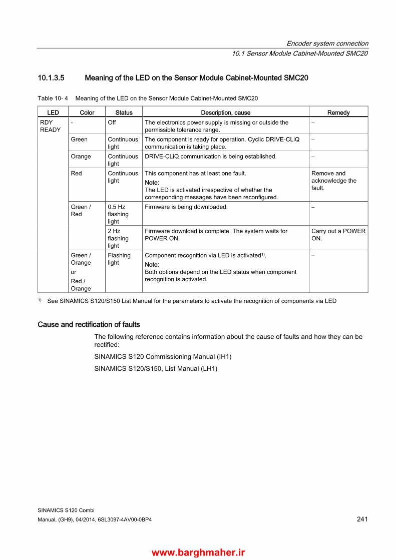
Encoder system connection 10.1 Sensor Module Cabinet-Mounted SMC20
SINAMICS S120 Combi Manual, (GH9), 04/2014, 6SL3097-4AV00-0BP4 241
10.1.3.5 Meaning of the LED on the Sensor Module Cabinet-Mounted SMC20
Table 10- 4 Meaning of the LED on the Sensor Module Cabinet-Mounted SMC20
LED Color Status Description, cause Remedy RDY READY
- Off The electronics power supply is missing or outside the permissible tolerance range.
–
Green Continuous light
The component is ready for operation. Cyclic DRIVE-CLiQ communication is taking place.
–
Orange Continuous light
DRIVE-CLiQ communication is being established. –
Red Continuous light
This component has at least one fault. Note: The LED is activated irrespective of whether the corresponding messages have been reconfigured.
Remove and acknowledge the fault.
Green / Red
0.5 Hz flashing light
Firmware is being downloaded. –
2 Hz flashing light
Firmware download is complete. The system waits for POWER ON.
Carry out a POWER ON.
Green / Orange or Red / Orange
Flashing light
Component recognition via LED is activated1). Note: Both options depend on the LED status when component recognition is activated.
–
1) See SINAMICS S120/S150 List Manual for the parameters to activate the recognition of components via LED
Cause and rectification of faults The following reference contains information about the cause of faults and how they can be rectified:
SINAMICS S120 Commissioning Manual (IH1)
SINAMICS S120/S150, List Manual (LH1)
www.barghmaher.ir
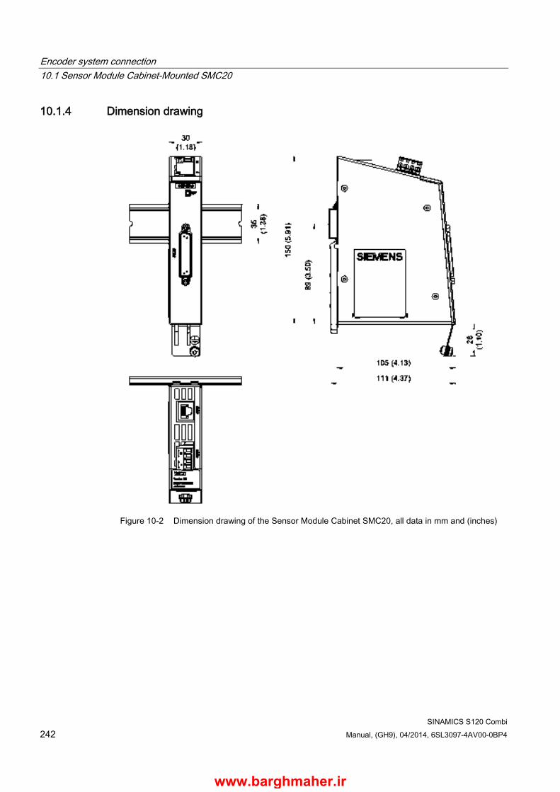
Encoder system connection 10.1 Sensor Module Cabinet-Mounted SMC20
SINAMICS S120 Combi 242 Manual, (GH9), 04/2014, 6SL3097-4AV00-0BP4
10.1.4 Dimension drawing
Figure 10-2 Dimension drawing of the Sensor Module Cabinet SMC20, all data in mm and (inches)
www.barghmaher.ir
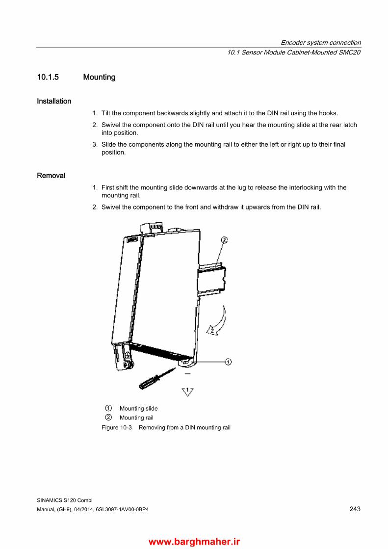
Encoder system connection 10.1 Sensor Module Cabinet-Mounted SMC20
SINAMICS S120 Combi Manual, (GH9), 04/2014, 6SL3097-4AV00-0BP4 243
10.1.5 Mounting
Installation 1. Tilt the component backwards slightly and attach it to the DIN rail using the hooks.
2. Swivel the component onto the DIN rail until you hear the mounting slide at the rear latch into position.
3. Slide the components along the mounting rail to either the left or right up to their final position.
Removal 1. First shift the mounting slide downwards at the lug to release the interlocking with the
mounting rail.
2. Swivel the component to the front and withdraw it upwards from the DIN rail.
① Mounting slide ② Mounting rail
Figure 10-3 Removing from a DIN mounting rail
www.barghmaher.ir
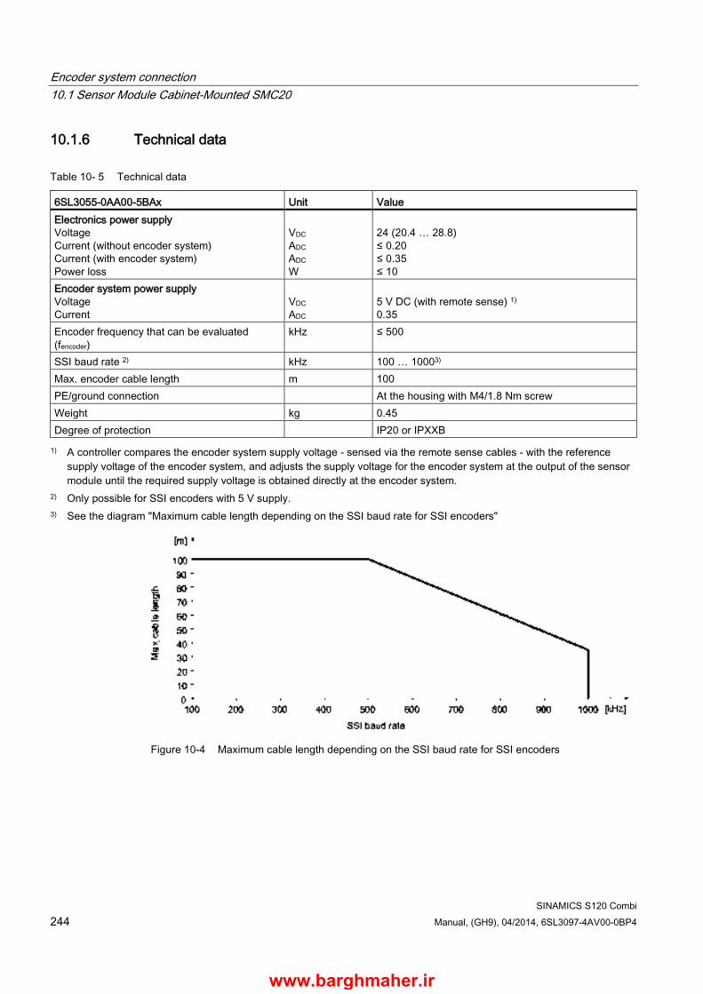
Encoder system connection 10.1 Sensor Module Cabinet-Mounted SMC20
SINAMICS S120 Combi 244 Manual, (GH9), 04/2014, 6SL3097-4AV00-0BP4
10.1.6 Technical data
Table 10- 5 Technical data
6SL3055-0AA00-5BAx Unit Value Electronics power supply Voltage Current (without encoder system) Current (with encoder system) Power loss
VDC ADC ADC W
24 (20.4 … 28.8) ≤ 0.20 ≤ 0.35 ≤ 10
Encoder system power supply Voltage Current
VDC ADC
5 V DC (with remote sense) 1) 0.35
Encoder frequency that can be evaluated (fencoder)
kHz ≤ 500
SSI baud rate 2) kHz 100 … 10003) Max. encoder cable length m 100 PE/ground connection At the housing with M4/1.8 Nm screw Weight kg 0.45 Degree of protection IP20 or IPXXB 1) A controller compares the encoder system supply voltage - sensed via the remote sense cables - with the reference
supply voltage of the encoder system, and adjusts the supply voltage for the encoder system at the output of the sensor module until the required supply voltage is obtained directly at the encoder system.
2) Only possible for SSI encoders with 5 V supply. 3) See the diagram "Maximum cable length depending on the SSI baud rate for SSI encoders"
Figure 10-4 Maximum cable length depending on the SSI baud rate for SSI encoders
www.barghmaher.ir
Encoder system connection 10.2 Sensor Module Cabinet-Mounted SMC30
SINAMICS S120 Combi Manual, (GH9), 04/2014, 6SL3097-4AV00-0BP4 245
10.2 Sensor Module Cabinet-Mounted SMC30
10.2.1 Description The Sensor Module Cabinet-Mounted SMC30 evaluates encoder signals and transmits the speed, actual position value and, if necessary, the motor temperature and reference point via DRIVE-CLiQ to the S120 Combi.
The SMC30 is used to evaluate encoder signals from encoders with TTL, HTL, or SSI interfaces.
A combination of TTL/HTL signal and SSI absolute signal is possible at terminals X521/X531, if both signals are derived from the same measured variable.
www.barghmaher.ir
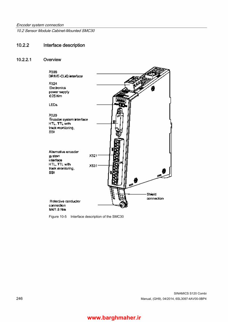
Encoder system connection 10.2 Sensor Module Cabinet-Mounted SMC30
SINAMICS S120 Combi 246 Manual, (GH9), 04/2014, 6SL3097-4AV00-0BP4
10.2.2 Interface description
10.2.2.1 Overview
Figure 10-5 Interface description of the SMC30
www.barghmaher.ir
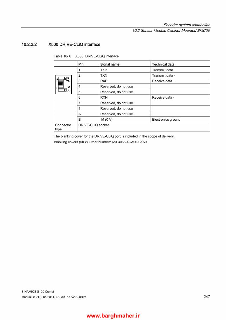
Encoder system connection 10.2 Sensor Module Cabinet-Mounted SMC30
SINAMICS S120 Combi Manual, (GH9), 04/2014, 6SL3097-4AV00-0BP4 247
10.2.2.2 X500 DRIVE-CLiQ interface
Table 10- 6 X500: DRIVE-CLiQ interface
Pin Signal name Technical data
1 TXP Transmit data + 2 TXN Transmit data - 3 RXP Receive data + 4 Reserved, do not use 5 Reserved, do not use 6 RXN Receive data - 7 Reserved, do not use 8 Reserved, do not use A Reserved, do not use B M (0 V) Electronics ground
Connector type
DRIVE-CLiQ socket
The blanking cover for the DRIVE-CLiQ port is included in the scope of delivery. Blanking covers (50 x) Order number: 6SL3066-4CA00-0AA0
www.barghmaher.ir

Encoder system connection 10.2 Sensor Module Cabinet-Mounted SMC30
SINAMICS S120 Combi 248 Manual, (GH9), 04/2014, 6SL3097-4AV00-0BP4
10.2.2.3 X520 encoder system interface
Table 10- 7 X520: Encoder system interface
Pin Signal name Technical data
1 +Temp Motor temperature sensing KTY84-1C130 (KTY+) Temperature sensor KTY84-1C130/PTC
2 Clock SSI clock 3 Clock* Inverse SSI clock 4 P encoder 5 V / 24 V Encoder power supply 5 P encoder 5 V / 24 V 6 P sense Sense input of encoder power supply 7 M encoder (M) Ground for encoder power supply 8 - Temp Motor temperature sensing KTY84-1C130 (KTY-)
Temperature sensor KTY84-1C130/PTC 9 M sense Ground sense input 10 R Reference signal R 11 R* Inverse reference signal R 12 B* Inverse incremental signal B 13 B Incremental signal B 14 A* / data* Inverted incremental signal A/inverted SSI data 15 A / data Incremental signal A/SSI data
Connector type: 15-pin Sub-D socket Measuring current via temperature sensor connection: 2 mA
NOTICE
Damage to the encoder due to incorrect supply voltage
The encoder supply can be parameterized to 5 V or 24 V. The sensor may be destroyed if you enter the wrong parameters. • Select the appropriate supply voltage.
NOTICE
Damage to motor in the event of incorrectly connected KTY temperature sensor
A KTY temperature sensor connected with incorrect polarity cannot detect if the motor overheats. Overheating can cause damage to the motor. • Connect a KTY temperature sensor with the correct polarity.
You can find information for parameterizing the KTY temperature sensor in the SINAMICS S120 Function Manual (FH1) in Chapter "Monitoring and protective functions/thermal motor monitoring".
www.barghmaher.ir

Encoder system connection 10.2 Sensor Module Cabinet-Mounted SMC30
SINAMICS S120 Combi Manual, (GH9), 04/2014, 6SL3097-4AV00-0BP4 249
WARNING
Danger to life due to electric shock in the event of voltage flashovers at the temperature sensor
Voltage flashovers in the signal electronics can occur in motors without safe electrical separation of the temperature sensors. • Use temperature sensors that fully comply with the specifications of the safety isolation. • If safe electrical separation cannot be guaranteed (for linear motors or third-party
motors, for example), use a Sensor Module External (SME120 or SME125) or Terminal Module TM120.
www.barghmaher.ir
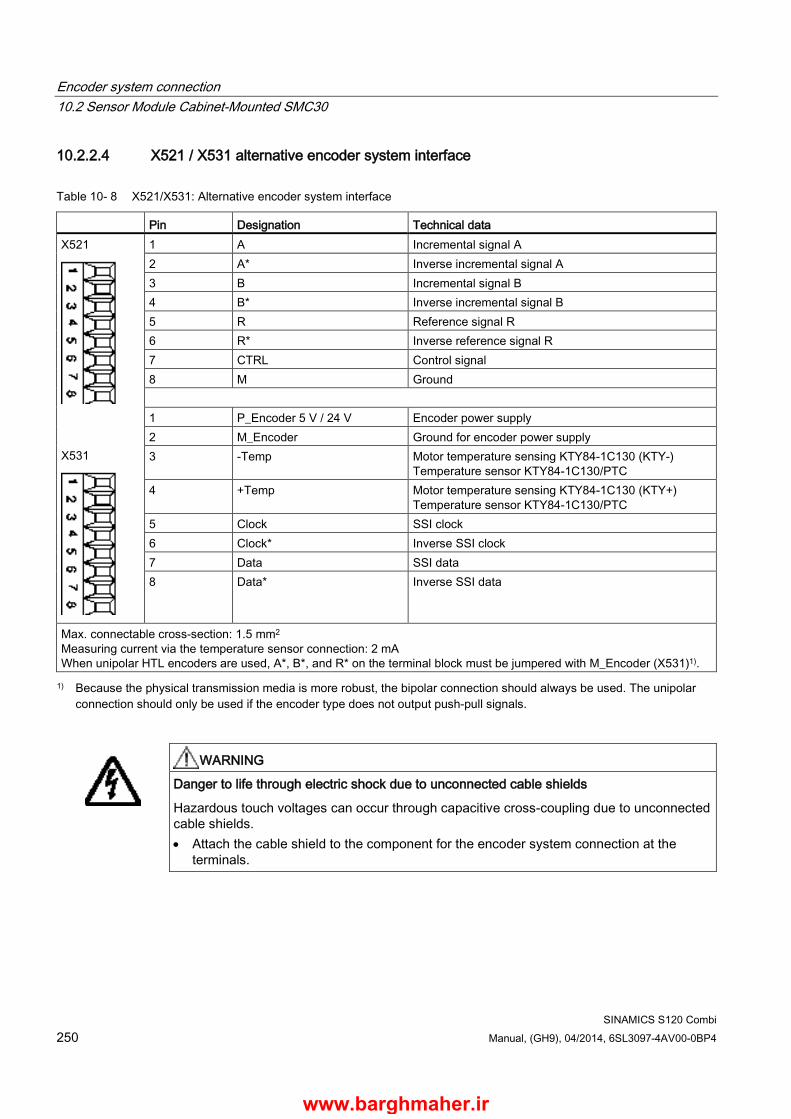
Encoder system connection 10.2 Sensor Module Cabinet-Mounted SMC30
SINAMICS S120 Combi 250 Manual, (GH9), 04/2014, 6SL3097-4AV00-0BP4
10.2.2.4 X521 / X531 alternative encoder system interface
Table 10- 8 X521/X531: Alternative encoder system interface
Pin Designation Technical data X521
X531
1 A Incremental signal A 2 A* Inverse incremental signal A 3 B Incremental signal B 4 B* Inverse incremental signal B 5 R Reference signal R 6 R* Inverse reference signal R 7 CTRL Control signal 8 M Ground 1 P_Encoder 5 V / 24 V Encoder power supply 2 M_Encoder Ground for encoder power supply 3 -Temp Motor temperature sensing KTY84-1C130 (KTY-)
Temperature sensor KTY84-1C130/PTC 4 +Temp Motor temperature sensing KTY84-1C130 (KTY+)
Temperature sensor KTY84-1C130/PTC 5 Clock SSI clock 6 Clock* Inverse SSI clock 7 Data SSI data 8 Data* Inverse SSI data
Max. connectable cross-section: 1.5 mm2
Measuring current via the temperature sensor connection: 2 mA When unipolar HTL encoders are used, A*, B*, and R* on the terminal block must be jumpered with M_Encoder (X531)1). 1) Because the physical transmission media is more robust, the bipolar connection should always be used. The unipolar
connection should only be used if the encoder type does not output push-pull signals.
WARNING
Danger to life through electric shock due to unconnected cable shields
Hazardous touch voltages can occur through capacitive cross-coupling due to unconnected cable shields. • Attach the cable shield to the component for the encoder system connection at the
terminals.
www.barghmaher.ir
Encoder system connection 10.2 Sensor Module Cabinet-Mounted SMC30
SINAMICS S120 Combi Manual, (GH9), 04/2014, 6SL3097-4AV00-0BP4 251
Temperature sensor connection
NOTICE
Damage to motor in the event of incorrectly connected KTY temperature sensor
A KTY temperature sensor connected with incorrect polarity cannot detect if the motor overheats. Overheating can cause damage to the motor. • Connect a KTY temperature sensor with the correct polarity.
You can find information for parameterizing the KTY temperature sensor in the SINAMICS S120 Function Manual (FH1) in Chapter "Monitoring and protective functions/thermal motor monitoring".
Note
The maximum length of the temperature sensor cable is 100 m. The cables must be shielded.
WARNING
Danger to life due to electric shock in the event of voltage flashovers at the temperature sensor
Voltage flashovers in the signal electronics can occur in motors without safe electrical separation of the temperature sensors. • Use temperature sensors that fully comply with the specifications of the safety isolation. • If safe electrical separation cannot be guaranteed (for linear motors or third-party
motors, for example), use a Sensor Module External (SME120 or SME125) or Terminal Module TM120.
www.barghmaher.ir

Encoder system connection 10.2 Sensor Module Cabinet-Mounted SMC30
SINAMICS S120 Combi 252 Manual, (GH9), 04/2014, 6SL3097-4AV00-0BP4
10.2.2.5 X524 Electronics power supply
Table 10- 9 X524: Electronics power supply
Terminal Function Technical data
+ Electronics power supply Voltage: 24 V (20.4 … 28.8 V) Current consumption: max. 0.55 A Max. current via jumper in connector: 20 A Type: Screw terminal 2 (Page 309) Max. connectable cross-section: 2.5 mm2 Tightening torque: 0.22 … 0.25 Nm
+ Electronics power supply M Electronics ground M Electronics ground
Note
The two "+" and "M" terminals are jumpered in the connector. This ensures that the supply voltage is looped through.
www.barghmaher.ir
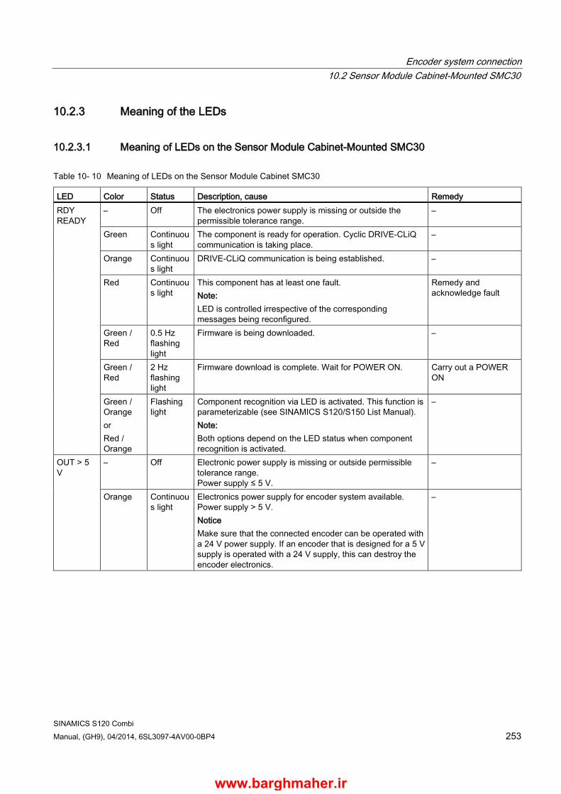
Encoder system connection 10.2 Sensor Module Cabinet-Mounted SMC30
SINAMICS S120 Combi Manual, (GH9), 04/2014, 6SL3097-4AV00-0BP4 253
10.2.3 Meaning of the LEDs
10.2.3.1 Meaning of LEDs on the Sensor Module Cabinet-Mounted SMC30
Table 10- 10 Meaning of LEDs on the Sensor Module Cabinet SMC30
LED Color Status Description, cause Remedy RDY READY
– Off The electronics power supply is missing or outside the permissible tolerance range.
–
Green Continuous light
The component is ready for operation. Cyclic DRIVE-CLiQ communication is taking place.
–
Orange Continuous light
DRIVE-CLiQ communication is being established. –
Red Continuous light
This component has at least one fault. Note: LED is controlled irrespective of the corresponding messages being reconfigured.
Remedy and acknowledge fault
Green / Red
0.5 Hz flashing light
Firmware is being downloaded. –
Green / Red
2 Hz flashing light
Firmware download is complete. Wait for POWER ON. Carry out a POWER ON
Green / Orange or Red / Orange
Flashing light
Component recognition via LED is activated. This function is parameterizable (see SINAMICS S120/S150 List Manual). Note: Both options depend on the LED status when component recognition is activated.
–
OUT > 5 V
– Off Electronic power supply is missing or outside permissible tolerance range. Power supply ≤ 5 V.
–
Orange Continuous light
Electronics power supply for encoder system available. Power supply > 5 V. Notice Make sure that the connected encoder can be operated with a 24 V power supply. If an encoder that is designed for a 5 V supply is operated with a 24 V supply, this can destroy the encoder electronics.
–
www.barghmaher.ir
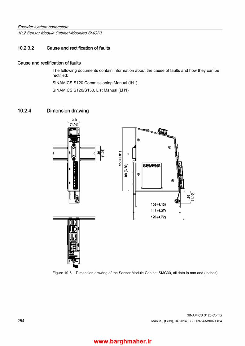
Encoder system connection 10.2 Sensor Module Cabinet-Mounted SMC30
SINAMICS S120 Combi 254 Manual, (GH9), 04/2014, 6SL3097-4AV00-0BP4
10.2.3.2 Cause and rectification of faults
Cause and rectification of faults The following documents contain information about the cause of faults and how they can be rectified:
SINAMICS S120 Commissioning Manual (IH1)
SINAMICS S120/S150, List Manual (LH1)
10.2.4 Dimension drawing
Figure 10-6 Dimension drawing of the Sensor Module Cabinet SMC30, all data in mm and (inches)
www.barghmaher.ir

Encoder system connection 10.2 Sensor Module Cabinet-Mounted SMC30
SINAMICS S120 Combi Manual, (GH9), 04/2014, 6SL3097-4AV00-0BP4 255
10.2.5 Mounting
Installation 1. Tilt the component backwards slightly and attach it to the DIN rail using the hooks.
2. Swivel the component onto the DIN rail until you hear the mounting slide at the rear latch into position.
3. Slide the components along the mounting rail to either the left or right up to their final position.
Removal 1. First shift the mounting slide downwards at the lug to release the interlocking with the
mounting rail.
2. Swivel the component to the front and withdraw it upwards from the DIN rail.
① Mounting slide ② Mounting rail
Figure 10-7 Removing from a DIN mounting rail
www.barghmaher.ir
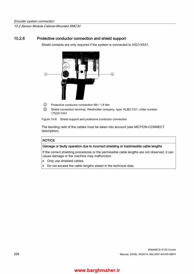
Encoder system connection 10.2 Sensor Module Cabinet-Mounted SMC30
SINAMICS S120 Combi 256 Manual, (GH9), 04/2014, 6SL3097-4AV00-0BP4
10.2.6 Protective conductor connection and shield support Shield contacts are only required if the system is connected to X521/X531.
① Protective conductor connection M4 / 1.8 Nm ② Shield connection terminal, Weidmüller company, type: KLBÜ CO1, order number:
1753311001
Figure 10-8 Shield support and protective conductor connection
The bending radii of the cables must be taken into account (see MOTION-CONNECT description).
NOTICE
Damage or faulty operation due to incorrect shielding or inadmissible cable lengths
If the correct shielding procedures or the permissible cable lengths are not observed, it can cause damage or the machine may malfunction. • Only use shielded cables. • Do not exceed the cable lengths stated in the technical data.
www.barghmaher.ir
Encoder system connection 10.2 Sensor Module Cabinet-Mounted SMC30
SINAMICS S120 Combi Manual, (GH9), 04/2014, 6SL3097-4AV00-0BP4 257
10.2.7 Technical data
Table 10- 11 Technical data
6SL3055-0AA00-5CAx Unit Value Electronics power supply Voltage Current (without encoder system) Current (with encoder system) Power loss
VDC ADC ADC W
24 (20,4 … 28,8) ≤ 0,20 ≤ 0,55 ≤ 10
Encoder system power supply Voltage Current
VDC ADC
5 (with or without remote sense) 1) or VDC - 1 V 0.35
Encoder frequency that can be evaluated (fencoder)
kHz ≤ 300
SSI baud rate kHz 100 … 10002) PE/ground connection At the housing with M4/1.8 Nm screw Weight 0.45 Degree of protection IP20 or IPXXB 1) A controller compares the encoder system supply voltage - sensed via the Remote Sense cables - with the reference
supply voltage of the encoder system, and adjusts the supply voltage for the encoder system at the output of the sensor module until the required supply voltage is obtained directly at the encoder system (only for 5 V encoder system power supply). Remote Sense only to X520.
2) See the diagram "Maximum cable length depending on the SSI baud rate for SSI encoders"
www.barghmaher.ir

Encoder system connection 10.2 Sensor Module Cabinet-Mounted SMC30
SINAMICS S120 Combi 258 Manual, (GH9), 04/2014, 6SL3097-4AV00-0BP4
Connectable encoder systems
Table 10- 12 Specification of encoder systems that can be connected
Parameter Designation Threshold Min. Max. Unit High signal level (TTL bipolar at X520 or X521/X531)1)
UHdiff 2 5 V
Low signal level (TTL bipolar at X520 or X521/X531)1)
ULdiff -5 -2 V
High signal level (HTL unipolar)
UH3) High 17 VCC V Low 10 VCC V
Low signal level (HTL unipolar)
UL3) High 0 7 V Low 0 2 V
High signal level (HTL bipolar)2)
UHdiff 3 VCC V
Low signal level (HTL bipolar) 2)
ULdiff -VCC -3 V
High signal level (SSI bipolar at X520 or X521/X531)1)
UHdiff 2 5 V
Low signal level (SSI bipolar at X520 or X521/X531)1)
ULdiff -5 -2 V
Signal frequency fS - 300 kHz Edge clearance tmin 100 - ns "Zero pulse inactive time" (before and after A=B=high)
tLo 640 (tALo-BHi - tHi)/24) ns
"Zero pulse active time" (while A=B=high and beyond) 5)
tHi 640 tALo-BHi - 2*tLo 4) ns
1) Other signal levels according to the RS 422 standard. 2) The absolute level of the individual signals varies between 0 V and VCC of the encoder system. 3) Only with order number 6SL3055-0AA00-5CA2 and firmware version 2.5 SP1 or higher can this value be configured
using software. For older firmware releases and Order Nos. less than 6SL3055-0AA00-5CA2 then the "low" threshold applies.
4) tALo-BHi is not a specified value, but is the time between the falling edge of track A and the next but one rising edge of track B.
5) Additional information on setting the "Zero pulse active time" can be found in the manual: SINAMICS S120, Function Manual, tolerant encoder monitoring for SMC30
www.barghmaher.ir

Encoder system connection 10.2 Sensor Module Cabinet-Mounted SMC30
SINAMICS S120 Combi Manual, (GH9), 04/2014, 6SL3097-4AV00-0BP4 259
Table 10- 13 Encoders that can be connected
X520 (SUB-D)
X521 (terminal)
X531 (terminal)
Track monitoring
Remote Sense2)
HTL bipolar 24 V Yes Yes Yes No HTL unipolar 24 V 1) Yes Yes (however, a bipolar
connection is recommended)1) No No
TTL bipolar 24 V Yes Yes Yes No TTL bipolar 5 V Yes Yes Yes At X520 SSI 24 V/5 V Yes Yes No No TTL unipolar No 1) Because the physical transmission media is more robust, the bipolar connection should always be used. The unipolar
connection should only be used if the encoder type does not output push-pull signals. 2) A controller compares the encoder system supply voltage - sensed via the Remote Sense cables - with the reference
supply voltage of the encoder system, and adjusts the supply voltage for the encoder system at the output of the sensor module until the required supply voltage is obtained directly at the encoder system (only for 5 V encoder system power supply).
Maximum encoder cable lengths
Table 10- 14 Maximum encoder cable length
Encoder type Maximum encoder cable length in m TTL1) 100 HTL unipolar2) 100 HTL bipolar 300 SSI 1003) 1) For TTL encoders at X520 → remote sense → 100 m
2) Because the physical transmission media is more robust, the bipolar connection should always be used. The unipolar connection should only be used if the encoder type does not output push-pull signals.
3) See the diagram "Maximum cable length depending on the SSI baud rate for SSI encoders"
www.barghmaher.ir

Encoder system connection 10.2 Sensor Module Cabinet-Mounted SMC30
SINAMICS S120 Combi 260 Manual, (GH9), 04/2014, 6SL3097-4AV00-0BP4
SSI encoder
Figure 10-9 Maximum cable length depending on the SSI baud rate for SSI encoders
www.barghmaher.ir
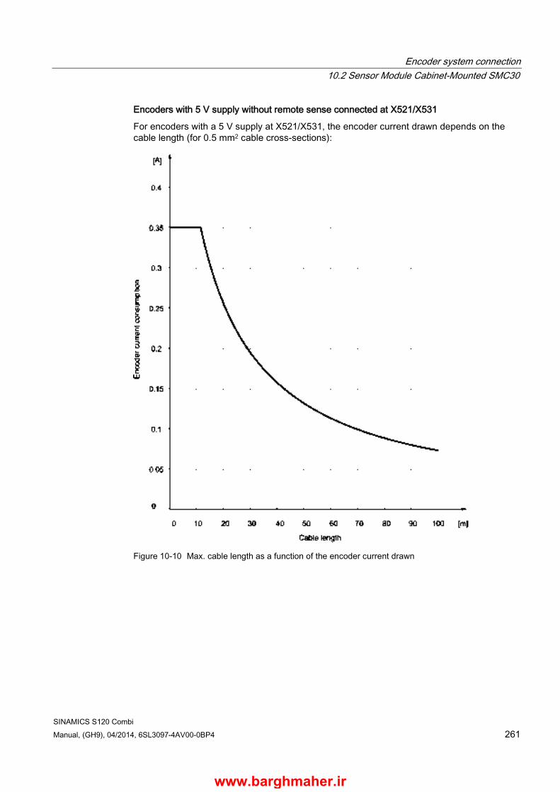
Encoder system connection 10.2 Sensor Module Cabinet-Mounted SMC30
SINAMICS S120 Combi Manual, (GH9), 04/2014, 6SL3097-4AV00-0BP4 261
Encoders with 5 V supply without remote sense connected at X521/X531
For encoders with a 5 V supply at X521/X531, the encoder current drawn depends on the cable length (for 0.5 mm2 cable cross-sections):
Figure 10-10 Max. cable length as a function of the encoder current drawn
www.barghmaher.ir
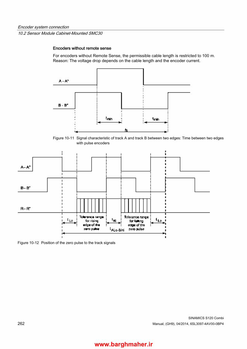
Encoder system connection 10.2 Sensor Module Cabinet-Mounted SMC30
SINAMICS S120 Combi 262 Manual, (GH9), 04/2014, 6SL3097-4AV00-0BP4
Encoders without remote sense
For encoders without Remote Sense, the permissible cable length is restricted to 100 m. Reason: The voltage drop depends on the cable length and the encoder current.
Figure 10-11 Signal characteristic of track A and track B between two edges: Time between two edges
with pulse encoders
Figure 10-12 Position of the zero pulse to the track signals
www.barghmaher.ir
Encoder system connection 10.3 Sensor Module External SME20
SINAMICS S120 Combi Manual, (GH9), 04/2014, 6SL3097-4AV00-0BP4 263
10.3 Sensor Module External SME20
10.3.1 Description Direct encoder systems outside the cabinet can be connected to the Sensor Module External SME20. The SME20 evaluates these encoder systems and converts the calculated values to DRIVE-CLiQ.
Incremental direct encoder systems with SIN/COS (1 Vpp) and reference signal can be connected.
It is possible to connect a motor with a 17-pole circular connector for the encoder to the 12-pole circular connector of the SME20 using adapter cable 6FX 8002-2CA88-xxxx.
● KTY/PTC temperature sensors can be used for evaluation of the motor temperature.
● The Sensor Module is only suitable for motors without absolute track signals (C/D track):
– Induction motors (e.g. 1PH)
– Synchronous motors with pole position identification (e.g. 1FN, 1FW, 1FE)
Neither motor nor encoder data are saved in the SME20.
10.3.2 Safety Information
WARNING
Danger to life due to electric shock in the event of voltage flashovers at the temperature sensor
Voltage flashovers in the signal electronics can occur in motors without safe electrical separation of the temperature sensors. • Only use temperature sensors that fully comply with the specifications of the safety
isolation. • If safe electrical separation cannot be guaranteed (for linear motors or third-party
motors, for example), use a Sensor Module External (SME120 or SME125) or Terminal Module TM120.
www.barghmaher.ir
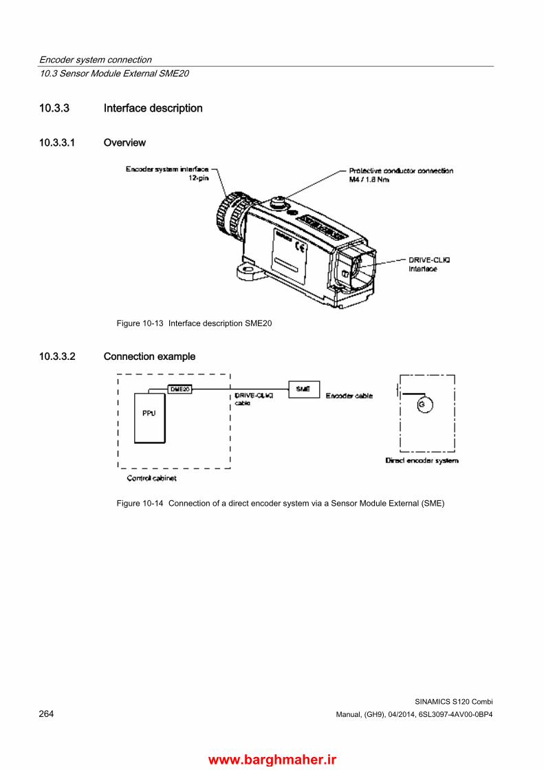
Encoder system connection 10.3 Sensor Module External SME20
SINAMICS S120 Combi 264 Manual, (GH9), 04/2014, 6SL3097-4AV00-0BP4
10.3.3 Interface description
10.3.3.1 Overview
Figure 10-13 Interface description SME20
10.3.3.2 Connection example
Figure 10-14 Connection of a direct encoder system via a Sensor Module External (SME)
www.barghmaher.ir

Encoder system connection 10.3 Sensor Module External SME20
SINAMICS S120 Combi Manual, (GH9), 04/2014, 6SL3097-4AV00-0BP4 265
10.3.3.3 DRIVE-CLiQ interface
Table 10- 15 DRIVE-CLiQ interface
Pin Signal name Technical data
1 TXP Transmit data + 2 TXN Transmit data - 3 RXP Receive data + 4 Reserved, do not use 5 Reserved, do not use 6 RXN Receive data - 7 Reserved, do not use 8 Reserved, do not use A + (24 V) Power supply B M (0 V) Electronics ground
Connector type
DRIVE-CLiQ socket
Power consumption max. 0.25 A The blanking cover for the DRIVE-CLiQ port to secure the degree of protection IP 67 is not included in
the scope of delivery. Blanking covers (6 pcs) order number: 6SL3066-4CA01-0AA0
Note
Only MOTION-CONNECT DRIVE-CLiQ cables may be used for connections. The maximum cable length is 100 m for MOTION-CONNECT 500, and 75 m for MOTION-CONNECT 800PLUS cables.
www.barghmaher.ir
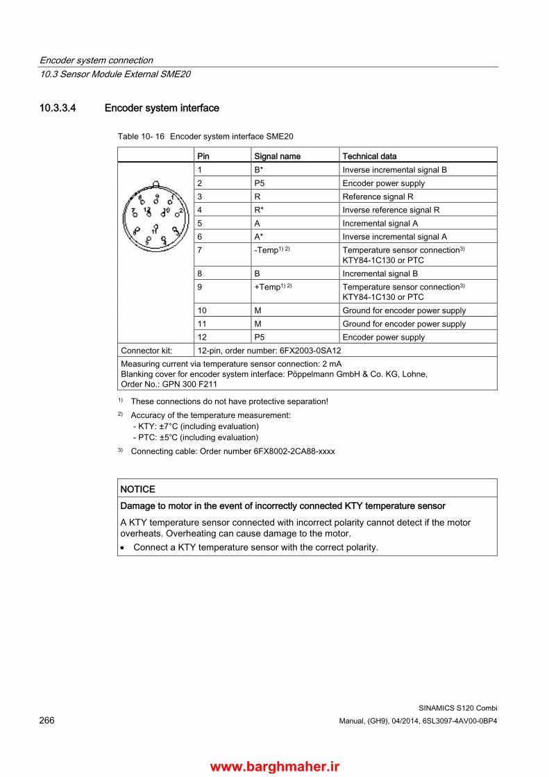
Encoder system connection 10.3 Sensor Module External SME20
SINAMICS S120 Combi 266 Manual, (GH9), 04/2014, 6SL3097-4AV00-0BP4
10.3.3.4 Encoder system interface
Table 10- 16 Encoder system interface SME20
Pin Signal name Technical data
1 B* Inverse incremental signal B 2 P5 Encoder power supply 3 R Reference signal R 4 R* Inverse reference signal R 5 A Incremental signal A 6 A* Inverse incremental signal A 7 -Temp1) 2) Temperature sensor connection3)
KTY84-1C130 or PTC 8 B Incremental signal B 9 +Temp1) 2) Temperature sensor connection3)
KTY84-1C130 or PTC 10 M Ground for encoder power supply 11 M Ground for encoder power supply 12 P5 Encoder power supply
Connector kit: 12-pin, order number: 6FX2003-0SA12 Measuring current via temperature sensor connection: 2 mA Blanking cover for encoder system interface: Pöppelmann GmbH & Co. KG, Lohne, Order No.: GPN 300 F211 1) These connections do not have protective separation!
2) Accuracy of the temperature measurement: - KTY: ±7°C (including evaluation) - PTC: ±5℃ (including evaluation)
3) Connecting cable: Order number 6FX8002-2CA88-xxxx
NOTICE
Damage to motor in the event of incorrectly connected KTY temperature sensor
A KTY temperature sensor connected with incorrect polarity cannot detect if the motor overheats. Overheating can cause damage to the motor. • Connect a KTY temperature sensor with the correct polarity.
www.barghmaher.ir

Encoder system connection 10.3 Sensor Module External SME20
SINAMICS S120 Combi Manual, (GH9), 04/2014, 6SL3097-4AV00-0BP4 267
WARNING
Danger to life due to electric shock in the event of voltage flashovers at the temperature sensor
Voltage flashovers in the signal electronics can occur in motors without safe electrical separation of the temperature sensors. • Use temperature sensors that fully comply with the specifications of the safety isolation. • If safe electrical separation cannot be guaranteed (for linear motors or third-party
motors, for example), use a Sensor Module External (SME120 or SME125) or Terminal Module TM120.
10.3.4 Dimension drawing
Figure 10-15 Dimension drawing of Sensor Module External SME20, all data in mm and (inches), order number 6SL3055-0AA00-5EA3
www.barghmaher.ir

Encoder system connection 10.3 Sensor Module External SME20
SINAMICS S120 Combi 268 Manual, (GH9), 04/2014, 6SL3097-4AV00-0BP4
10.3.5 Installation
① Contact surface
Figure 10-16 Drilling pattern for installing the SME20/SME25
Installation 1. Place the drilling pattern on the mounting surface. Make sure that the contact surface is
bare, unpainted metal.
2. Drill two holes with Ø 5.3 or M5 threaded holes according to the drilling pattern.
3. Fix the Sensor Module to the mounting surface. The tightening torque is 6 Nm.
www.barghmaher.ir

Encoder system connection 10.3 Sensor Module External SME20
SINAMICS S120 Combi Manual, (GH9), 04/2014, 6SL3097-4AV00-0BP4 269
10.3.6 Technical data
Table 10- 17 Technical data
6SL3055-0AA00-5EA3 Unit Value Electronics power supply Voltage Current (without encoder system) Current (with encoder system) Power loss
VDC ADC ADC W
24 (20.4 … 28.8) ≤ 0.15 ≤ 0.25 ≤ 4
Encoder system power supply Voltage Current
VDC ADC
5 0.35
Encoder frequency that can be evaluated (fencoder)
kHz ≤ 500
PE/ground connection At the housing with M4/1.8 Nm screw Weight kg 0.31 Degree of protection IP67
The maximum cable length at the encoder system interface depends on the current consumption of the encoder system and the cross-section of the supply cores in the cable. However, the maximum length is 10 m.
For encoder systems that operate in a supply voltage range from 4.75 V to 5.25 V, the following diagram is obtained. The sample parameters shown are 0.28 mm² cross-section (0.14 mm² supply cores plus 0.14 mm² remote sense conductors) and 0.64 mm² (0.5 mm² supply conductors plus 0.14 mm² remote sense conductors).
www.barghmaher.ir

Encoder system connection 10.3 Sensor Module External SME20
SINAMICS S120 Combi 270 Manual, (GH9), 04/2014, 6SL3097-4AV00-0BP4
Figure 10-17 Max. cable length as a function of the current drawn by the encoder system
In addition to the encoder systems for a supply voltage range of 4.75 V to 5.25 V in the figure above, encoder systems are also available for an extended range down to 3.6 V. These can be generally operated using encoder system cables up to 10 m long provided that the total cross-section of the supply core plus Remote Sense cores does not fall below 0.14 mm².
www.barghmaher.ir
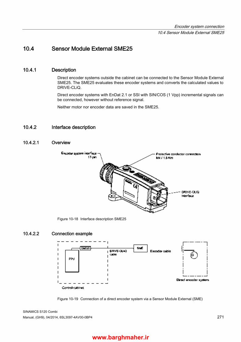
Encoder system connection 10.4 Sensor Module External SME25
SINAMICS S120 Combi Manual, (GH9), 04/2014, 6SL3097-4AV00-0BP4 271
10.4 Sensor Module External SME25
10.4.1 Description Direct encoder systems outside the cabinet can be connected to the Sensor Module External SME25. The SME25 evaluates these encoder systems and converts the calculated values to DRIVE-CLiQ.
Direct encoder systems with EnDat 2.1 or SSI with SIN/COS (1 Vpp) incremental signals can be connected, however without reference signal.
Neither motor nor encoder data are saved in the SME25.
10.4.2 Interface description
10.4.2.1 Overview
Figure 10-18 Interface description SME25
10.4.2.2 Connection example
Figure 10-19 Connection of a direct encoder system via a Sensor Module External (SME)
www.barghmaher.ir

Encoder system connection 10.4 Sensor Module External SME25
SINAMICS S120 Combi 272 Manual, (GH9), 04/2014, 6SL3097-4AV00-0BP4
10.4.2.3 DRIVE-CLiQ interface
Table 10- 18 DRIVE-CLiQ interface
Pin Signal name Technical data
1 TXP Transmit data + 2 TXN Transmit data - 3 RXP Receive data + 4 Reserved, do not use 5 Reserved, do not use 6 RXN Receive data - 7 Reserved, do not use 8 Reserved, do not use A + (24 V) Power supply B M (0 V) Electronics ground
Connector type
DRIVE-CLiQ socket
Power consumption max. 0.25 A The blanking cover for the DRIVE-CLiQ port to secure the degree of protection IP 67 is not included in
the scope of delivery. Blanking covers (6 pcs) order number: 6SL3066-4CA01-0AA0
Note
Only MOTION-CONNECT DRIVE-CLiQ cables may be used for connections. The maximum cable length is 100 m for MOTION-CONNECT 500, and 75 m for MOTION-CONNECT 800PLUS cables.
www.barghmaher.ir

Encoder system connection 10.4 Sensor Module External SME25
SINAMICS S120 Combi Manual, (GH9), 04/2014, 6SL3097-4AV00-0BP4 273
10.4.2.4 Encoder system interface
Table 10- 19 Encoder system interface SME25
Pin Signal name Technical specifications
1 P5 Encoder power supply 2 Reserved, do not use 3 Reserved, do not use 4 M Ground for encoder power supply 5 +Temp Temperature sensor connection
KTY84-1C130 or PTC 6 -Temp 7 P5 Encoder power supply 8 Clock Clock, EnDat interface,
SSI clock1) 9 Clock* Inverse clock, EnDat interface,
Inverse SSI clock1) 10 M Ground for encoder power supply 11 Enclosure potential 12 B Incremental signal B 13 B* Inverse incremental signal B 14 Data Data, EnDat interface,
SSI data1) 15 A Incremental signal A 16 A* Inverse incremental signal A 17 Data* Inverse data EnDat interface,
Inverse SSI data1) Blanking plate for encoder system interface: Pöppelmann GmbH & Co. KG, Lohne, Order No.: GPN 300 F211 connector kits, 17-pin, Order No.: 6FX2003-0SA17
NOTICE
Damage due to an incorrectly connected KTY temperature sensor
If the KTY temperature sensor was not connected with the correct polarity, motor overheating may not be detected. • Connect the KTY temperature sensor with the correct polarity.
www.barghmaher.ir

Encoder system connection 10.4 Sensor Module External SME25
SINAMICS S120 Combi 274 Manual, (GH9), 04/2014, 6SL3097-4AV00-0BP4
WARNING
Danger to life due to electric shock in the event of voltage flashovers at the temperature sensor
Voltage flashovers in the signal electronics can occur in motors without safe electrical separation of the temperature sensors. • Use temperature sensors that fully comply with the specifications of the safety isolation. • If safe electrical separation cannot be guaranteed (for linear motors or third-party
motors, for example), use a Sensor Module External (SME120 or SME125) or Terminal Module TM120.
10.4.3 Dimension drawing
Figure 10-20 Dimension drawing of Sensor Module External SME25, all data in mm and (inches), order number 6SL3055-0AA00-5HA3
www.barghmaher.ir
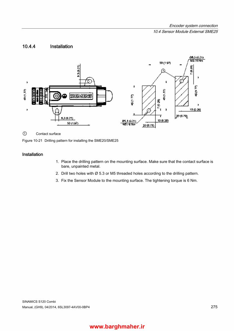
Encoder system connection 10.4 Sensor Module External SME25
SINAMICS S120 Combi Manual, (GH9), 04/2014, 6SL3097-4AV00-0BP4 275
10.4.4 Installation
① Contact surface
Figure 10-21 Drilling pattern for installing the SME20/SME25
Installation 1. Place the drilling pattern on the mounting surface. Make sure that the contact surface is
bare, unpainted metal.
2. Drill two holes with Ø 5.3 or M5 threaded holes according to the drilling pattern.
3. Fix the Sensor Module to the mounting surface. The tightening torque is 6 Nm.
www.barghmaher.ir
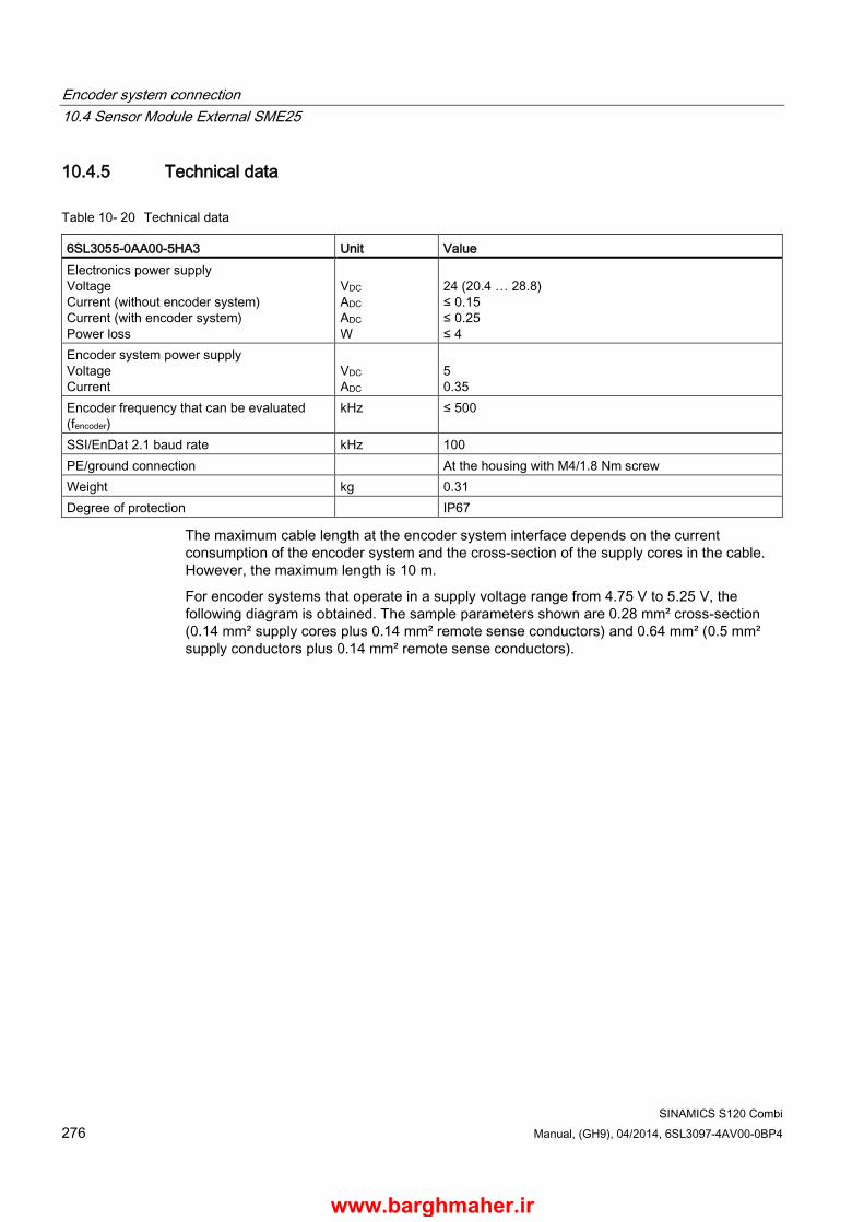
Encoder system connection 10.4 Sensor Module External SME25
SINAMICS S120 Combi 276 Manual, (GH9), 04/2014, 6SL3097-4AV00-0BP4
10.4.5 Technical data
Table 10- 20 Technical data
6SL3055-0AA00-5HA3 Unit Value Electronics power supply Voltage Current (without encoder system) Current (with encoder system) Power loss
VDC ADC ADC W
24 (20.4 … 28.8) ≤ 0.15 ≤ 0.25 ≤ 4
Encoder system power supply Voltage Current
VDC ADC
5 0.35
Encoder frequency that can be evaluated (fencoder)
kHz ≤ 500
SSI/EnDat 2.1 baud rate kHz 100 PE/ground connection At the housing with M4/1.8 Nm screw Weight kg 0.31 Degree of protection IP67
The maximum cable length at the encoder system interface depends on the current consumption of the encoder system and the cross-section of the supply cores in the cable. However, the maximum length is 10 m.
For encoder systems that operate in a supply voltage range from 4.75 V to 5.25 V, the following diagram is obtained. The sample parameters shown are 0.28 mm² cross-section (0.14 mm² supply cores plus 0.14 mm² remote sense conductors) and 0.64 mm² (0.5 mm² supply conductors plus 0.14 mm² remote sense conductors).
www.barghmaher.ir
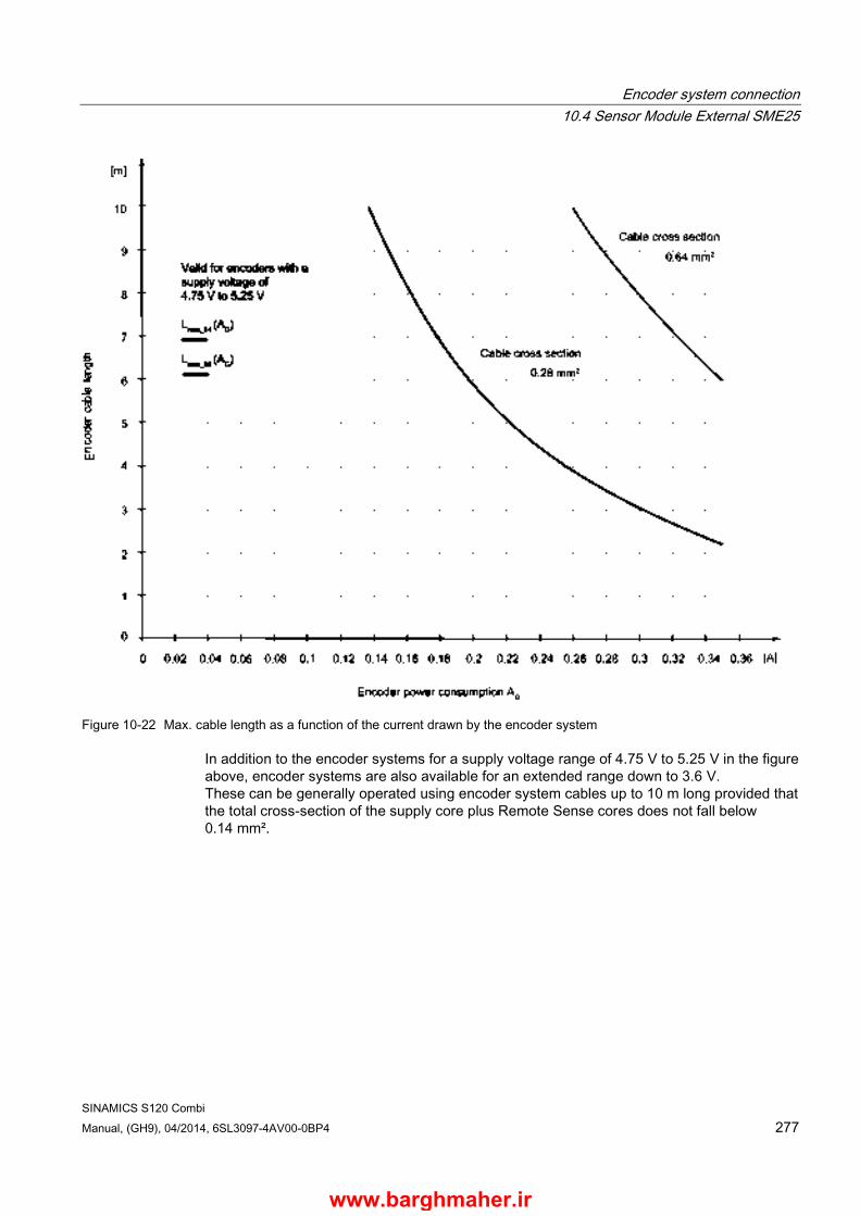
Encoder system connection 10.4 Sensor Module External SME25
SINAMICS S120 Combi Manual, (GH9), 04/2014, 6SL3097-4AV00-0BP4 277
Figure 10-22 Max. cable length as a function of the current drawn by the encoder system
In addition to the encoder systems for a supply voltage range of 4.75 V to 5.25 V in the figure above, encoder systems are also available for an extended range down to 3.6 V. These can be generally operated using encoder system cables up to 10 m long provided that the total cross-section of the supply core plus Remote Sense cores does not fall below 0.14 mm².
www.barghmaher.ir

Encoder system connection 10.4 Sensor Module External SME25
SINAMICS S120 Combi 278 Manual, (GH9), 04/2014, 6SL3097-4AV00-0BP4
www.barghmaher.ir

SINAMICS S120 Combi Manual, (GH9), 04/2014, 6SL3097-4AV00-0BP4 279
Accessories 11 11.1 DRIVE-CLiQ cabinet bushing
11.1.1 Description A DRIVE-CLiQ cabinet bushing is used to connect the DRIVE-CLiQ cables between the inside and outside of the control cabinet. It is used in a control cabinet panel. The data lines and the voltage supply contacts of the DRIVE-CLiQ are also routed through the bushing. The DRIVE-CLiQ cabinet bushing for DRIVE-CLiQ cables is available with DRIVE-CLiQ connector and M12 connector/socket.
DRIVE-CLiQ cabinet bushing for DRIVE-CLiQ connectors
The cabinet bushing has degree of protection IP54 according to EN 60529 from the outside towards the inside. Inside the control cabinet, a connection is established according to degree of protection IP20 or IPXXB acc. to EN 60529. So that the complete outside of the cabinet bushing, including the DRIVE-CLiQ interface, has degree of protection IP54, a DRIVE-CLiQ cable must be used, which as a minimum must also have degree of protection IP54.
DRIVE-CLiQ cabinet bushing for M12 plug/socket
The cabinet bushing has degree of protection IP67 according to EN 60529 from the outside towards the inside. Inside the cabinet a connection according to degree of protection IP67 in compliance with EN 60529 is realized.
www.barghmaher.ir
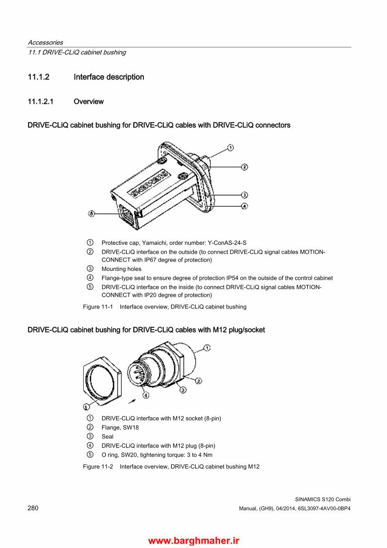
Accessories 11.1 DRIVE-CLiQ cabinet bushing
SINAMICS S120 Combi 280 Manual, (GH9), 04/2014, 6SL3097-4AV00-0BP4
11.1.2 Interface description
11.1.2.1 Overview
DRIVE-CLiQ cabinet bushing for DRIVE-CLiQ cables with DRIVE-CLiQ connectors
① Protective cap, Yamaichi, order number: Y-ConAS-24-S ② DRIVE-CLiQ interface on the outside (to connect DRIVE-CLiQ signal cables MOTION-
CONNECT with IP67 degree of protection) ③ Mounting holes ④ Flange-type seal to ensure degree of protection IP54 on the outside of the control cabinet ⑤ DRIVE-CLiQ interface on the inside (to connect DRIVE-CLiQ signal cables MOTION-
CONNECT with IP20 degree of protection)
Figure 11-1 Interface overview, DRIVE-CLiQ cabinet bushing
DRIVE-CLiQ cabinet bushing for DRIVE-CLiQ cables with M12 plug/socket
① DRIVE-CLiQ interface with M12 socket (8-pin) ② Flange, SW18 ③ Seal ④ DRIVE-CLiQ interface with M12 plug (8-pin) ⑤ O ring, SW20, tightening torque: 3 to 4 Nm
Figure 11-2 Interface overview, DRIVE-CLiQ cabinet bushing M12
www.barghmaher.ir
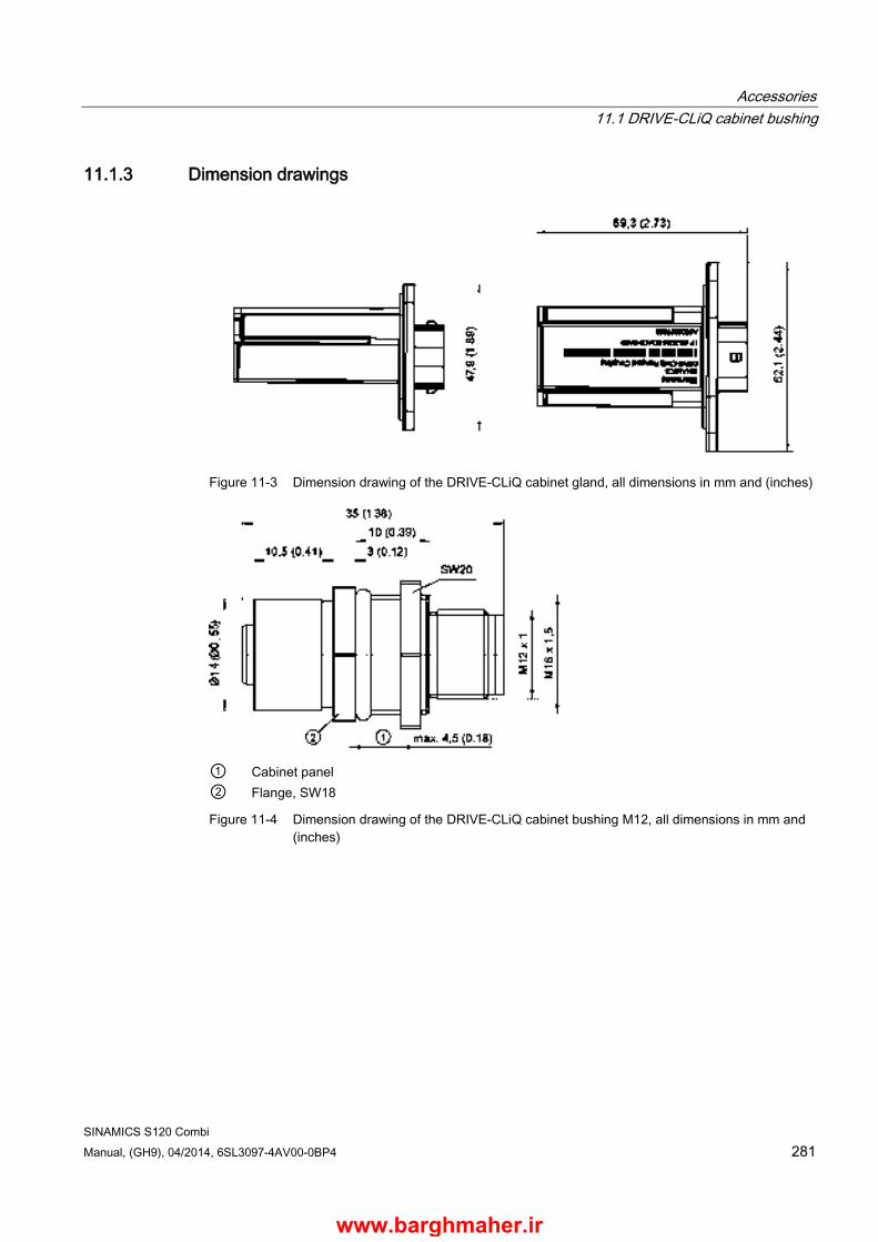
Accessories 11.1 DRIVE-CLiQ cabinet bushing
SINAMICS S120 Combi Manual, (GH9), 04/2014, 6SL3097-4AV00-0BP4 281
11.1.3 Dimension drawings
Figure 11-3 Dimension drawing of the DRIVE-CLiQ cabinet gland, all dimensions in mm and (inches)
① Cabinet panel ② Flange, SW18
Figure 11-4 Dimension drawing of the DRIVE-CLiQ cabinet bushing M12, all dimensions in mm and (inches)
www.barghmaher.ir

Accessories 11.1 DRIVE-CLiQ cabinet bushing
SINAMICS S120 Combi 282 Manual, (GH9), 04/2014, 6SL3097-4AV00-0BP4
11.1.4 DRIVE-CLiQ cabinet bushing for cables with DRIVE-CLiQ connectors In order to install the DRIVE-CLiQ cabinet gland, you must make a cutout in the control cabinet panel as shown in the diagram below.
Figure 11-5 Cutout in the control cabinet, all dimensions in mm and (inches)
www.barghmaher.ir
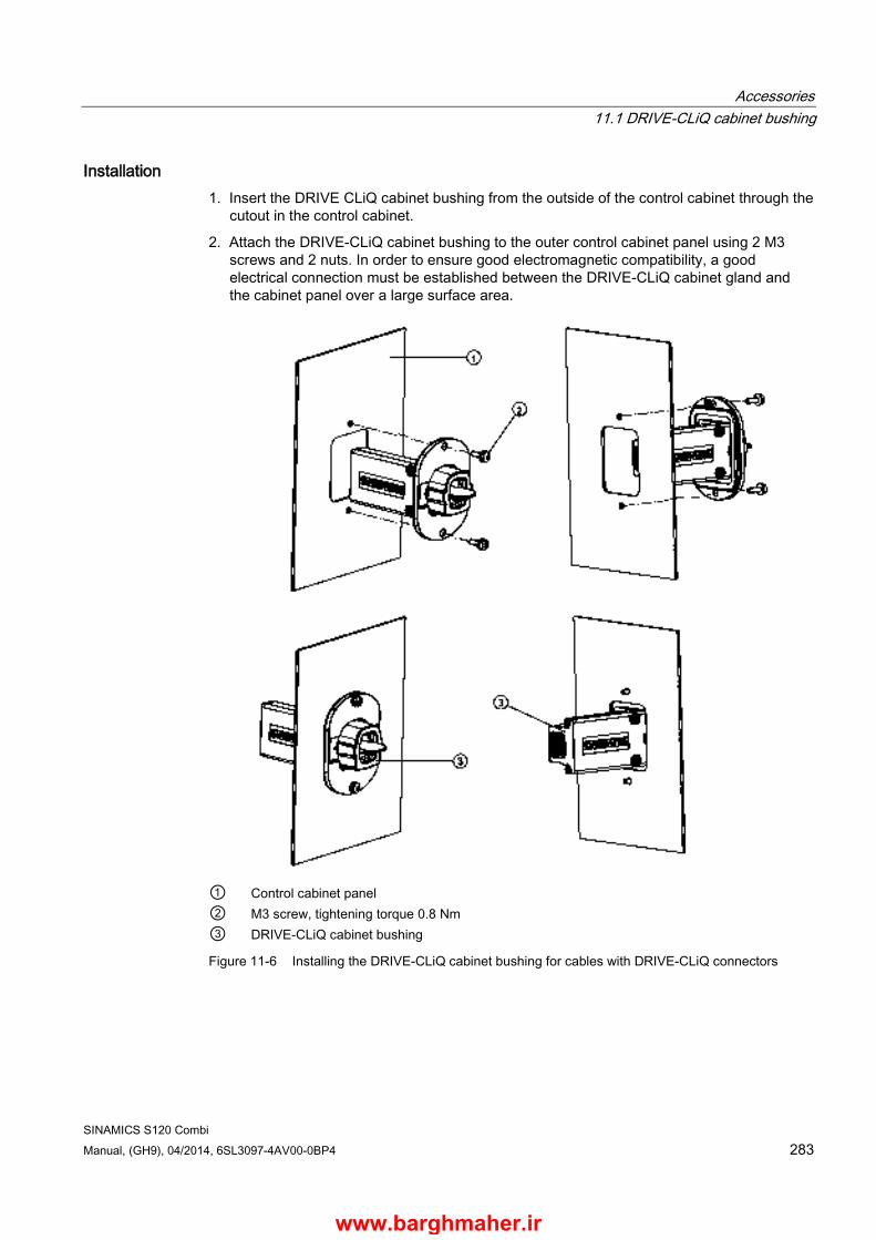
Accessories 11.1 DRIVE-CLiQ cabinet bushing
SINAMICS S120 Combi Manual, (GH9), 04/2014, 6SL3097-4AV00-0BP4 283
Installation 1. Insert the DRIVE CLiQ cabinet bushing from the outside of the control cabinet through the
cutout in the control cabinet.
2. Attach the DRIVE-CLiQ cabinet bushing to the outer control cabinet panel using 2 M3 screws and 2 nuts. In order to ensure good electromagnetic compatibility, a good electrical connection must be established between the DRIVE-CLiQ cabinet gland and the cabinet panel over a large surface area.
① Control cabinet panel ② M3 screw, tightening torque 0.8 Nm ③ DRIVE-CLiQ cabinet bushing
Figure 11-6 Installing the DRIVE-CLiQ cabinet bushing for cables with DRIVE-CLiQ connectors
www.barghmaher.ir

Accessories 11.1 DRIVE-CLiQ cabinet bushing
SINAMICS S120 Combi 284 Manual, (GH9), 04/2014, 6SL3097-4AV00-0BP4
11.1.5 Technical data
Table 11- 1 Technical data of DRIVE-CLiQ cabinet bushings
Unit 6SL3066-2DA00-0AA0 DRIVE-CLiQ
6FX2003-0DT67 M12
Weight kg 0.165 0.035 Degree of protection according to EN 60529
IP54 outside the control cabinet IP20 or IPXXB inside the control cabinet
IP67
www.barghmaher.ir
Accessories 11.2 DRIVE-CLiQ coupling
SINAMICS S120 Combi Manual, (GH9), 04/2014, 6SL3097-4AV00-0BP4 285
11.2 DRIVE-CLiQ coupling
11.2.1 Description The DRIVE-CLiQ coupling is used to connect two DRIVE-CLiQ cables in accordance with degree of protection IP67 acc. to EN 60529.
In addition to the data lines, the power supply contacts of DRIVE-CLiQ are also routed via the coupling.
Information on the permissible cable length can be found in Section "DRIVE-CLiQ signal cables (Page 303)".
11.2.2 Safety information
NOTICE
Damage through use of incorrect DRIVE-CLiQ cables
Damage or malfunctions can occur on the devices or system when DRIVE-CLiQ cables are used that are either incorrect or have not been approved for this purpose. • Only use suitable DRIVE-CLiQ cables that have been approved by Siemens for the
particular application.
www.barghmaher.ir
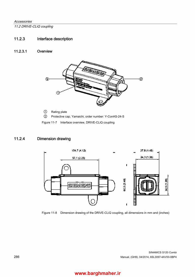
Accessories 11.2 DRIVE-CLiQ coupling
SINAMICS S120 Combi 286 Manual, (GH9), 04/2014, 6SL3097-4AV00-0BP4
11.2.3 Interface description
11.2.3.1 Overview
① Rating plate ② Protective cap, Yamaichi, order number: Y-ConAS-24-S
Figure 11-7 Interface overview, DRIVE-CLiQ coupling
11.2.4 Dimension drawing
Figure 11-8 Dimension drawing of the DRIVE-CLiQ coupling, all dimensions in mm and (inches)
www.barghmaher.ir
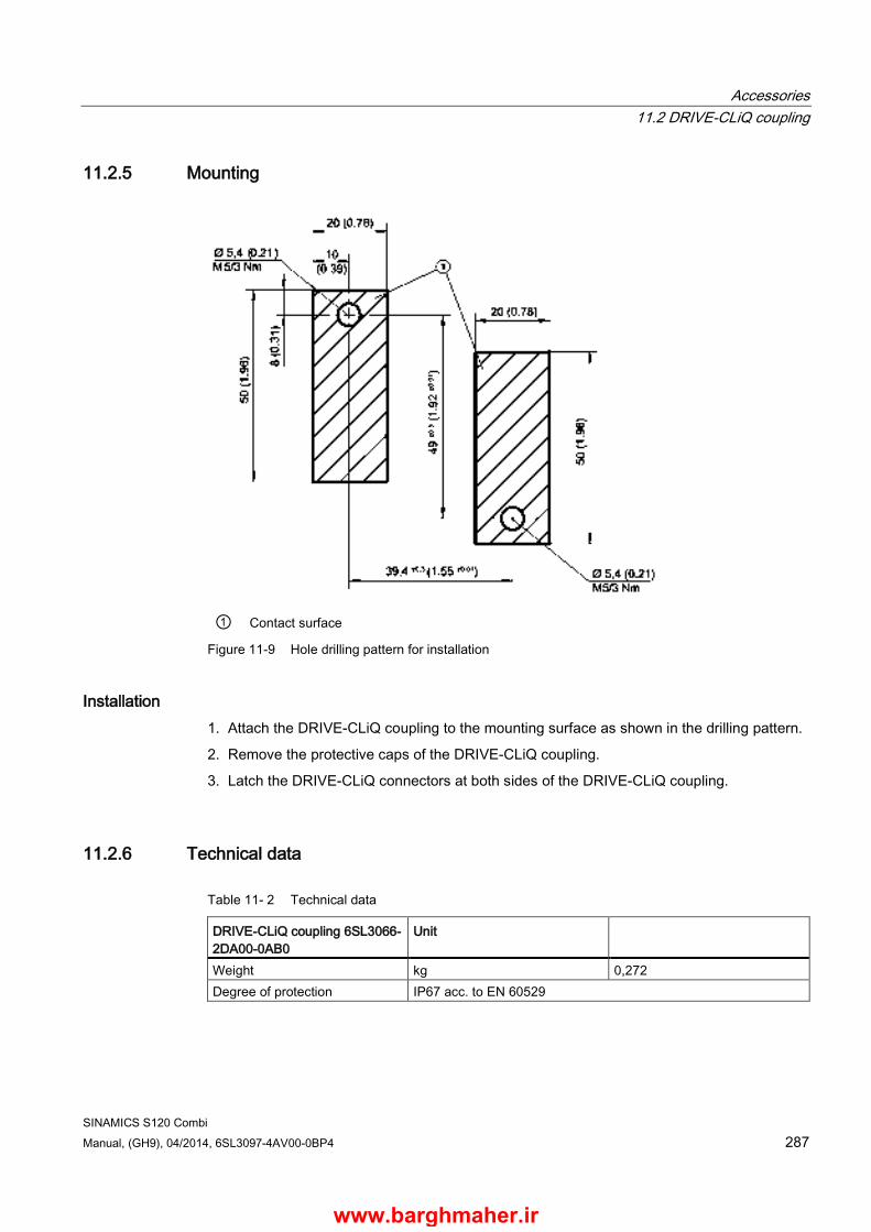
Accessories 11.2 DRIVE-CLiQ coupling
SINAMICS S120 Combi Manual, (GH9), 04/2014, 6SL3097-4AV00-0BP4 287
11.2.5 Mounting
① Contact surface
Figure 11-9 Hole drilling pattern for installation
Installation 1. Attach the DRIVE-CLiQ coupling to the mounting surface as shown in the drilling pattern.
2. Remove the protective caps of the DRIVE-CLiQ coupling.
3. Latch the DRIVE-CLiQ connectors at both sides of the DRIVE-CLiQ coupling.
11.2.6 Technical data
Table 11- 2 Technical data
DRIVE-CLiQ coupling 6SL3066-2DA00-0AB0
Unit
Weight kg 0,272 Degree of protection IP67 acc. to EN 60529
www.barghmaher.ir

Accessories 11.2 DRIVE-CLiQ coupling
SINAMICS S120 Combi 288 Manual, (GH9), 04/2014, 6SL3097-4AV00-0BP4
www.barghmaher.ir
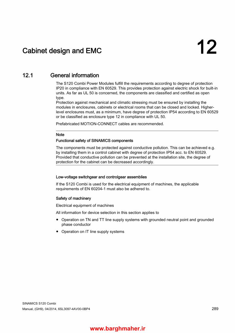
SINAMICS S120 Combi Manual, (GH9), 04/2014, 6SL3097-4AV00-0BP4 289
Cabinet design and EMC 12 12.1 General information
The S120 Combi Power Modules fulfill the requirements according to degree of protection IP20 in compliance with EN 60529. This provides protection against electric shock for built-in units. As far as UL 50 is concerned, the components are classified and certified as open type. Protection against mechanical and climatic stressing must be ensured by installing the modules in enclosures, cabinets or electrical rooms that can be closed and locked. Higher-level enclosures must, as a minimum, have degree of protection IP54 according to EN 60529 or be classified as enclosure type 12 in compliance with UL 50.
Prefabricated MOTION-CONNECT cables are recommended.
Note Functional safety of SINAMICS components
The components must be protected against conductive pollution. This can be achieved e.g. by installing them in a control cabinet with degree of protection IP54 acc. to EN 60529. Provided that conductive pollution can be prevented at the installation site, the degree of protection for the cabinet can be decreased accordingly.
Low-voltage switchgear and controlgear assemblies
If the S120 Combi is used for the electrical equipment of machines, the applicable requirements of EN 60204-1 must also be adhered to.
Safety of machinery
Electrical equipment of machines
All information for device selection in this section applies to
● Operation on TN and TT line supply systems with grounded neutral point and grounded phase conductor
● Operation on IT line supply systems
www.barghmaher.ir
Cabinet design and EMC 12.2 Safety information
SINAMICS S120 Combi 290 Manual, (GH9), 04/2014, 6SL3097-4AV00-0BP4
12.2 Safety information
WARNING
Danger to life if the fundamental safety instructions and remaining risks are not carefully observed
If the fundamental safety instructions and remaining risks in Chapter 1 (Page 19) are not observed, accidents involving severe injuries or death may occur. • Adhere to the fundamental safety instructions. • When assessing the risk, take into account residual risks.
WARNING
Danger to life due to malfunctions caused by conductive foreign matter
Foreign matter in the enclosure can cause the devices to malfunction. In turn, this affects the functional safety of machines and can therefore put people in danger or lead to material damage. • Cover the ventilation slots during installation of the control cabinet to prevent drill swarf,
end sleeves, and so on from falling into the enclosure, which could result in short-circuits or damage the insulation.
• Observe the safety regulations with regard to the touch protection. See also EN 60204-1.
NOTICE
Malfunctions and damage due to static discharge
If static discharge occurs on surfaces or interfaces that cannot be easily accessed, this can cause malfunctions and/or defects. • Only touch components, modules and devices if you are first grounded by applying one
of the following measures: – Wearing an ESD wrist strap – Wearing ESD shoes or ESD grounding straps in ESD areas with conductive flooring
www.barghmaher.ir
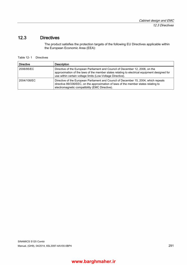
Cabinet design and EMC 12.3 Directives
SINAMICS S120 Combi Manual, (GH9), 04/2014, 6SL3097-4AV00-0BP4 291
12.3 Directives The product satisfies the protection targets of the following EU Directives applicable within the European Economic Area (EEA):
Table 12- 1 Directives
Directive Description 2006/95/EC Directive of the European Parliament and Council of December 12, 2006, on the
approximation of the laws of the member states relating to electrical equipment designed for use within certain voltage limits (Low-Voltage Directive).
2004/108/EC Directive of the European Parliament and Council of December 15, 2004, which repeals directive 89/336/EEC, on the approximation of laws of the member states relating to electromagnetic compatibility (EMC Directive).
www.barghmaher.ir
Cabinet design and EMC 12.4 Notes on electromagnetic compatibility (EMC)
SINAMICS S120 Combi 292 Manual, (GH9), 04/2014, 6SL3097-4AV00-0BP4
12.4 Notes on electromagnetic compatibility (EMC) Requirements to implement the EMC are listed in EN 61000-6-2, EN 61000-6-4, EN 61800-3, EN 60204-1 and in the Configuration Manual EMC Installation Guideline (order number 6FC5297-0AD30-0⃞P⃞). Conformance with the EMC Directive of the EC can be ensured by following the measures described in the Configuration Manual, EMC installation guideline. When mounting components in cabinets, in order to fulfill the EMC Directive, the following conditions must be additionally observed:
● Connected to TN and TT line supplies with grounded neutral point and grounded phase conductor as well as to IT line supplies.
● Observance of information about cable shielding and equipotential bonding.
● Use of the recommended power and signal cables from Siemens.
● Only cables from Siemens may be used for DRIVE-CLiQ connections.
NOTICE
Damage due to use of incorrect DRIVE-CLiQ couplings or cabinet glands
Damage or malfunctions can occur on the devices or system when incorrect or unreleased DRIVE-CLiQ couplings or cabinet glands are used. • Only use suitable DRIVE-CLiQ couplings and cabinet glands that have been released by
Siemens for the respective application.
DANGER
Danger to life due to electric shock in the event of faulty shielding
Death or serious injury can result when live parts are touched. • Ensure the correct shielding procedures are used.
WARNING
Fire hazard due to overheating when permissible cable lengths are exceeded
Excessively long cable lengths can cause components to overheat with the associated risk of fire and development of smoke. • The cable lengths (e.g. motor cable, DC link cable) listed in the technical data must not
be exceeded.
Note Radio interference due to high-frequency interference in residential environments
In a residential environment this product can cause high-frequency interference, which may make interference suppression measures necessary.
This device is not designed for unrestricted operation in the first environment (residential environment) and may not be used in the first environment without suitable interference suppression measures. • Have qualified personnel carry out the installation and commissioning with suitable
interference suppression measures.
www.barghmaher.ir

Cabinet design and EMC 12.5 Cable shielding and routing
SINAMICS S120 Combi Manual, (GH9), 04/2014, 6SL3097-4AV00-0BP4 293
12.5 Cable shielding and routing In order to comply with the EMC requirements, certain cables must be routed apart from other cables and from certain components. To full EMC requirements, the following cables must be used with shields:
● Line supply cables from the line filter via the line reactor to the S120 Combi Power Module
● All motor cables (if necessary, including cables for motor holding brake)
● Cables for analog direct voltage/current signals
● Signal cables for sensors
● Cables for temperature sensors
Alternative measures (e.g. routing behind mounting plates, suitable clearances) can also be used provided they have similar results. This excludes measures that relate to the design, installation, and routing of motor power cables and signal cables.
If unshielded cables are used between the line connection point and line filter, make sure that no interfering cables are routed in parallel.
Power and signal cables must always be routed separately. For this purpose, it is practical to arrange the various cables according to cable groups. Cables belonging to a group can be combined in a bundle. The various cable groups must be routed with the necessary clearance between them. A minimum clearance of 20 cm has proven itself in practice. As an alternative, shielding plates with the appropriate contacts at several locations can be used between the cable bundles.
All cables inside the cabinet should be laid as closely as possible to parts connected with cabinet ground, such as a mounting plate or cabinet wall. Ducts made of sheet steel or cables routed between steel sheets (e.g. between the mounting plate and back wall) should provide adequate shielding.
All cables must be kept as short as possible, to minimize the antenna effect.
Signal and power cables may cross each other (if absolutely necessary), but must never be routed closely to one and other in parallel over longer distances.
Signal cables must be routed with a minimum clearance of 20 cm from strong magnetic fields (motors, transformers). Alternatively, shield plates with the appropriate contacts at several locations along their length can be used to provide be appropriate clearance.
Note: Cables for the 24 V supply should be treated just like signal cables.
Avoid, where possible, routing non-shielded cables in the immediate vicinity of noise sources, e.g. transformers. Signal cables (shielded and unshielded) must be routed far away from strong external magnetic fields (e.g. transformers, line reactors). In both cases, a distance of ≥ 300 mm is usually sufficient.
Shield support
The cable shields must be connected as close to the conductor terminal connections as possible to ensure a low-impedance connection with cabinet ground. For power cables from Siemens in which the shield is connected to the connector shell (see relevant catalog), this is a sufficiently good shield support.
www.barghmaher.ir

Cabinet design and EMC 12.5 Cable shielding and routing
SINAMICS S120 Combi 294 Manual, (GH9), 04/2014, 6SL3097-4AV00-0BP4
For components that do not have any special shield connection or where the shield connection is not sufficient, the cable shields can be connected to the metal mounting plate using hose clamps and toothed rails. The cable length between the shield contact point and the terminals for cable cores must be kept as short as possible.
Routing 24 V cables When routing 24 V cables, the following must also be observed:
● A maximum of 1 conductor pair may be bundled together.
● 24 V conductors must be routed separately from other cables and conductors that could carry the operating current.
● 24 V cables must never be routed parallel to power cables.
● 24 V cables as well as power cables should be routed to the components so that they never cover ventilation slots.
Conditions of use for 24 V cables
● Ambient temperature 55 °C
● Conductor temperature limit ≤ 70° C for operation with the rated load current1)
● Cable length max.:
– 10 m for the 24 V supply cables
– 30 m for signal cables without a supplementary RC circuit 1) Conductor temperature limit 60 °C for UL applications
www.barghmaher.ir

Cabinet design and EMC 12.6 24 V DC supply
SINAMICS S120 Combi Manual, (GH9), 04/2014, 6SL3097-4AV00-0BP4 295
12.6 24 V DC supply
12.6.1 General information The 24 V DC voltage is required to supply the
1. electronics of the S120 Combi and the expansion axes (Motor Modules) via the integrated 24 V busbar
2. Electronics of the SINUMERIK 828D PPU, the Sensor Modules, the Terminal Module, the Braking Module, the DMx as well as the process voltage of its digital inputs
3. Load voltage of the digital outputs
4. Motor holding brake
Other loads can be connected to these power supply units if they are separately protected from overcurrent.
Note
The electronic power supply has to be supplied by the user as described in the System data (Page 30) section of this documentation.
When connecting to a "DC power supply" in the sense of EN 60204-1:1997, Chapter 4.3.3, functional faults can occur due to the voltage interruptions that are permitted there.
DANGER
Danger to life through electric shock due to a terminal voltage that has not been adjusted
Death or serious injury can result when live parts are touched. • Only connect protective extra-low voltages to all connections and terminals between 0
and 48 V DC.
NOTICE
Damage when other loads are connected
If other loads are connected to the power supply, overvoltage can damage all components • Fit the connected inductance devices (contactors, relays) with suitable overvoltage
protection circuits.
Note Malfunction because 24 V supply voltage is too low
If the 24 V supply voltage falls short of the specified minimum value on a device in the assembly, a malfunction can occur. • Select an input voltage that is high enough for there to be sufficient voltage on the last
device. Do not exceed the maximum value for the supply voltage. If required, supply the voltage to the assembly at various locations.
www.barghmaher.ir

Cabinet design and EMC 12.6 24 V DC supply
SINAMICS S120 Combi 296 Manual, (GH9), 04/2014, 6SL3097-4AV00-0BP4
Note
A regulated DC power supply is required to operate motors with a built-in holding brake. The voltage is supplied via the internal 24 V busbars. The voltage tolerances of the motor holding brakes (24 V ±10%) and the voltage drops of the connecting cables must be taken into account.
The DC power supply should be set to 26 V. The Control Supply Module supplies 26 V. This ensures that the supply voltage for the brake remains within the permissible range when the following conditions are fulfilled: • Use of Siemens three-phase motors • Use of Siemens MOTION-CONNECT power cables • Motor cable lengths, max. 50 m1)
1) 70 m for an 18 A supplementary axis
www.barghmaher.ir
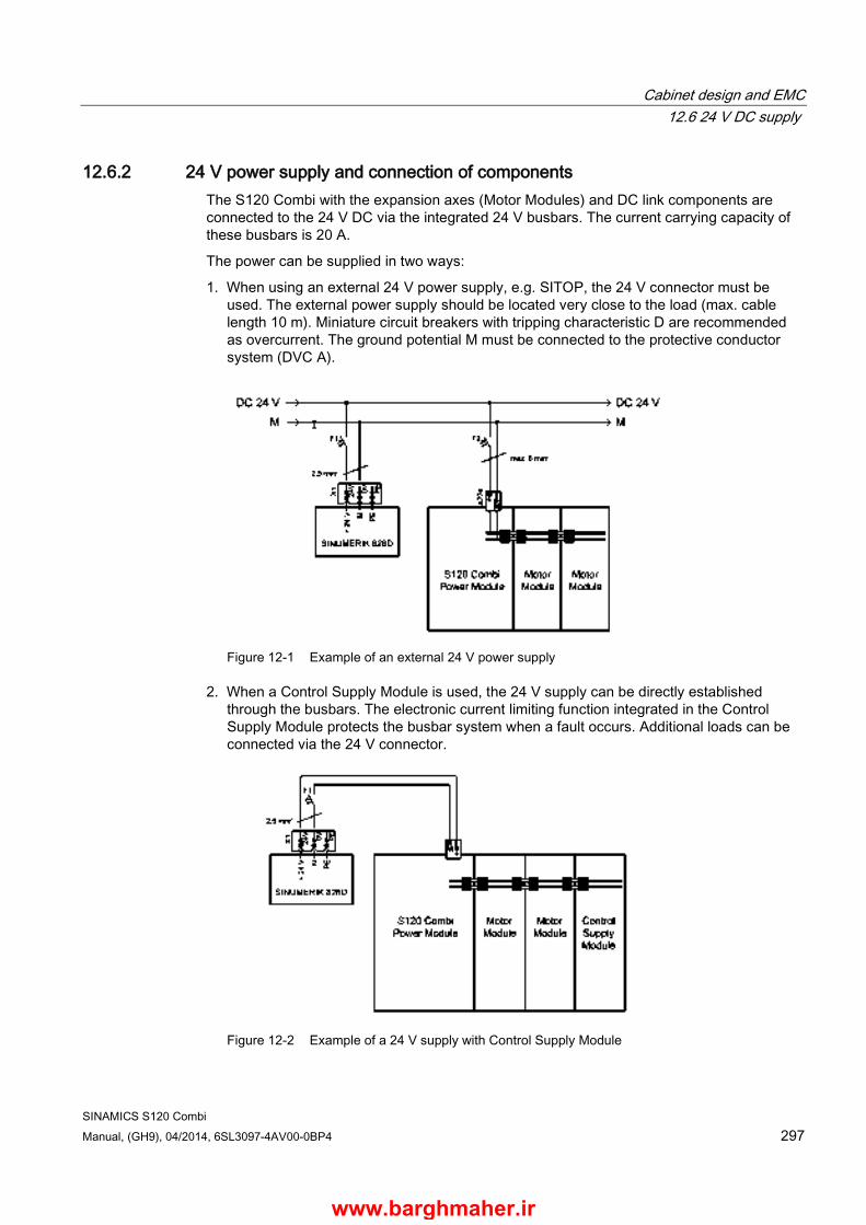
Cabinet design and EMC 12.6 24 V DC supply
SINAMICS S120 Combi Manual, (GH9), 04/2014, 6SL3097-4AV00-0BP4 297
12.6.2 24 V power supply and connection of components The S120 Combi with the expansion axes (Motor Modules) and DC link components are connected to the 24 V DC via the integrated 24 V busbars. The current carrying capacity of these busbars is 20 A.
The power can be supplied in two ways:
1. When using an external 24 V power supply, e.g. SITOP, the 24 V connector must be used. The external power supply should be located very close to the load (max. cable length 10 m). Miniature circuit breakers with tripping characteristic D are recommended as overcurrent. The ground potential M must be connected to the protective conductor system (DVC A).
Figure 12-1 Example of an external 24 V power supply
2. When a Control Supply Module is used, the 24 V supply can be directly established through the busbars. The electronic current limiting function integrated in the Control Supply Module protects the busbar system when a fault occurs. Additional loads can be connected via the 24 V connector.
Figure 12-2 Example of a 24 V supply with Control Supply Module
www.barghmaher.ir
Cabinet design and EMC 12.6 24 V DC supply
SINAMICS S120 Combi 298 Manual, (GH9), 04/2014, 6SL3097-4AV00-0BP4
Note
When using cables with a cross-section of 2.5 mm2, no additional protection is required on the 24 V side if a type XLPE or EPR cable, or a cable with a similar quality and with a thermal stability of up to 90 °C is used.
Using the 24 V connector ● A 24 V connector must be plugged onto the 24 V busbar between each S120 Combi,
expansion axis and DC-link component
● Insertion and withdrawal is only permissible in the no-voltage state
● Only 5 withdrawal and insertion cycles are permissible
www.barghmaher.ir

Cabinet design and EMC 12.6 24 V DC supply
SINAMICS S120 Combi Manual, (GH9), 04/2014, 6SL3097-4AV00-0BP4 299
12.6.3 Overcurrent protection in the 24 V solid-state circuit The cables on the primary and secondary sides of the 24 V power supply unit must be protected against overcurrent.
The protection on the primary side depends on the instructions of the equipment manufacturer. The protection on the secondary side depends on the actual conditions. Please note the following:
● Loading from loads, possibly the demand factor against the operation of the machine
● Current carrying capacity of the conductors used and cables in normal and short-circuit conditions
● Ambient temperature
● Cable bundling (laying cables in a common duct)
● Cable routing type
Overcurrent protective devices can be used in compliance with local installation regulations.
Circuit breakers according to the Siemens "NSK" catalog are recommended as overcurrent protection devices on the primary side. Miniature circuit breakers or SITOP select (order number 6EP1961-2BA00) are recommended as overcurrent protection devices on the secondary side. The MCBs can be selected according to Siemens catalog "BETA Modular Installation Devices - ET B1".
When selecting the miniature circuit breaker, local installation regulations must be carefully complied with.
Table 12- 2 MCBs by core cross-section and temperature
Core cross-section Max. value up to 40 °C Max. value up to 55 °C 1.5 mm2 10 A 6 A 2.5 mm2 16 A 10 A 4 mm2 25 A 16 A 6 mm2 32 A 20 A 24 V busbar 20 A 20 A
The trip characteristic of the MCBs must be selected to match the loads to be protected and the max. current provided by the power supply unit in the event of a short-circuit.
www.barghmaher.ir

Cabinet design and EMC 12.6 24 V DC supply
SINAMICS S120 Combi 300 Manual, (GH9), 04/2014, 6SL3097-4AV00-0BP4
12.6.4 Typical 24 V current consumption of the components A separate 24 V power supply must be used for the SINAMICS S120 drive group.
The following table can be used to calculate the 24 V DC power supply. The values for typical current consumption are used as a basis for configuration.
Table 12- 3 Overview of 24 V DC current consumption
Component Typical current consumption [ADC] Controller SINUMERIK 828D - PPU without load SINUMERIK 828D - PPU with full load (USB, handwheel, ...) SINUMERIK NCU 710.3 PN without load SINUMERIK NCU 710.3 PN with full load
1,2 2,5 0,9 11,7
Sensor Modules SMC20 without/with encoder system
0,20 / 0,355
SMC30 without/with encoder system
0,20 / 0,55
SME20 without/with encoder system
0,15 / 0,25
SME25 without/with encoder system
0,15 / 0,25
Terminal Modules TM54F (without digital outputs, without DRIVE-CLiQ) Per digital output/DRIVE-CLiQ
0,2 0,5
Additional system components DMC20 (without DRIVE-CLiQ) per DRIVE-CLiQ
0,15 0,5
DME20 (without DRIVE-CLiQ) per DRIVE-CLiQ
0,15 0,5
S120 Combi 3 axes Power Module 16 kW / 18 A / 5 A / 5 A 1,5 16 kW / 24 A / 9 A / 9 A 1,5 20 kW / 30 A / 9 A / 9 A 1,5 S120 Combi 4 axes Power Module 10 kW / 24 A / 12 A / 12 A / 12 A 1,6 16 kW / 18 A / 9 A / 5 A / 5 A 1,6 16 kW / 24 A / 9 A / 9 A / 9 A 1,6 20 kW / 30 A / 12 A / 9 A / 9 A 1,6 DRIVE-CLiQ and brake DRIVE-CLiQ (e.g. motors with DRIVE-CLiQ interface) 0,19 Brake (e.g. motor holding brake) Max. 1
www.barghmaher.ir
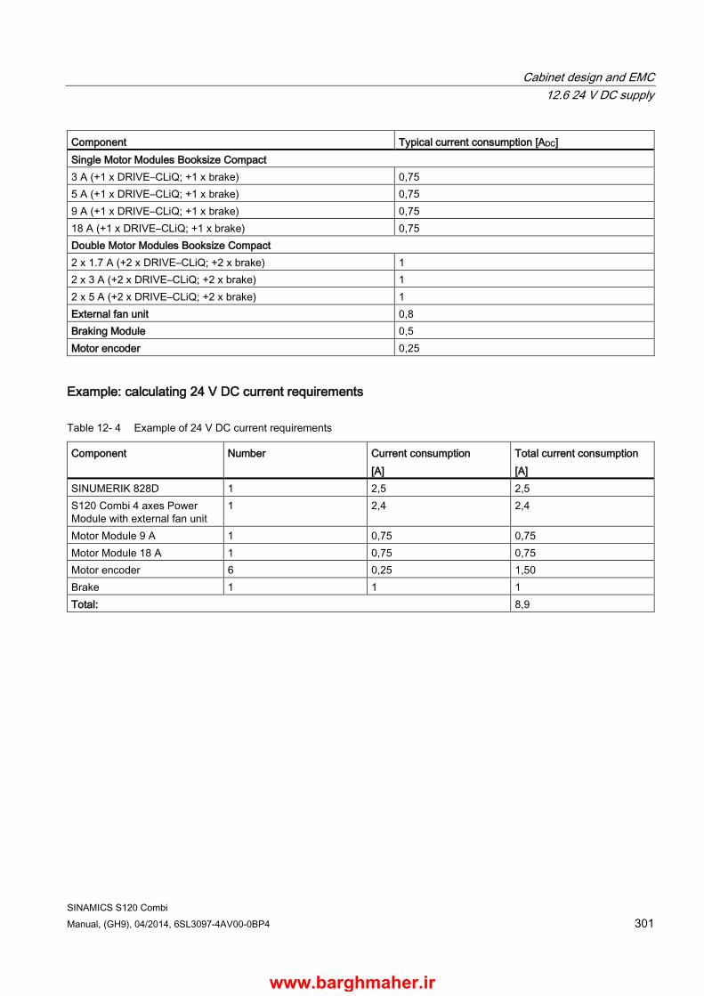
Cabinet design and EMC 12.6 24 V DC supply
SINAMICS S120 Combi Manual, (GH9), 04/2014, 6SL3097-4AV00-0BP4 301
Component Typical current consumption [ADC] Single Motor Modules Booksize Compact 3 A (+1 x DRIVE–CLiQ; +1 x brake) 0,75 5 A (+1 x DRIVE–CLiQ; +1 x brake) 0,75 9 A (+1 x DRIVE–CLiQ; +1 x brake) 0,75 18 A (+1 x DRIVE–CLiQ; +1 x brake) 0,75 Double Motor Modules Booksize Compact 2 x 1.7 A (+2 x DRIVE–CLiQ; +2 x brake) 1 2 x 3 A (+2 x DRIVE–CLiQ; +2 x brake) 1 2 x 5 A (+2 x DRIVE–CLiQ; +2 x brake) 1 External fan unit 0,8 Braking Module 0,5 Motor encoder 0,25
Example: calculating 24 V DC current requirements
Table 12- 4 Example of 24 V DC current requirements
Component Number Current consumption [A]
Total current consumption [A]
SINUMERIK 828D 1 2,5 2,5 S120 Combi 4 axes Power Module with external fan unit
1 2,4 2,4
Motor Module 9 A 1 0,75 0,75 Motor Module 18 A 1 0,75 0,75 Motor encoder 6 0,25 1,50 Brake 1 1 1 Total: 8,9
www.barghmaher.ir
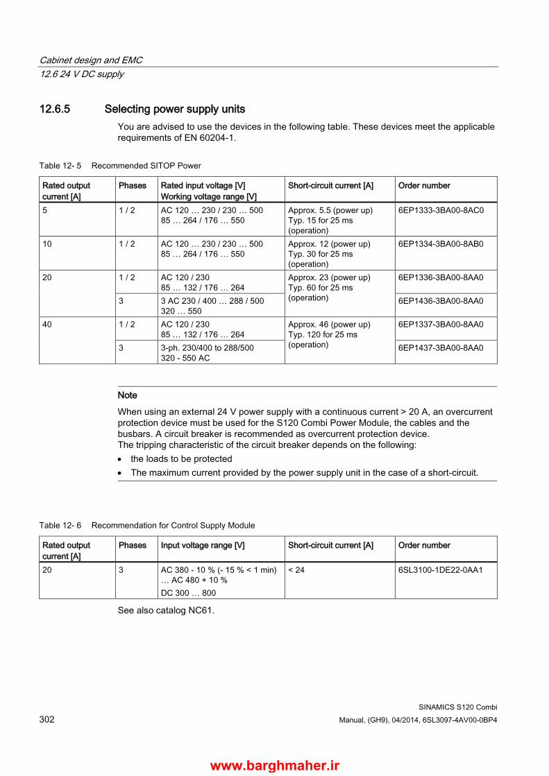
Cabinet design and EMC 12.6 24 V DC supply
SINAMICS S120 Combi 302 Manual, (GH9), 04/2014, 6SL3097-4AV00-0BP4
12.6.5 Selecting power supply units You are advised to use the devices in the following table. These devices meet the applicable requirements of EN 60204-1.
Table 12- 5 Recommended SITOP Power
Rated output current [A]
Phases Rated input voltage [V] Working voltage range [V]
Short-circuit current [A] Order number
5 1 / 2 AC 120 … 230 / 230 … 500 85 … 264 / 176 … 550
Approx. 5.5 (power up) Typ. 15 for 25 ms (operation)
6EP1333-3BA00-8AC0
10 1 / 2 AC 120 … 230 / 230 … 500 85 … 264 / 176 … 550
Approx. 12 (power up) Typ. 30 for 25 ms (operation)
6EP1334-3BA00-8AB0
20 1 / 2 AC 120 / 230 85 … 132 / 176 … 264
Approx. 23 (power up) Typ. 60 for 25 ms (operation)
6EP1336-3BA00-8AA0
3 3 AC 230 / 400 … 288 / 500 320 … 550
6EP1436-3BA00-8AA0
40 1 / 2 AC 120 / 230 85 … 132 / 176 … 264
Approx. 46 (power up) Typ. 120 for 25 ms (operation)
6EP1337-3BA00-8AA0
3 3-ph. 230/400 to 288/500 320 - 550 AC
6EP1437-3BA00-8AA0
Note
When using an external 24 V power supply with a continuous current > 20 A, an overcurrent protection device must be used for the S120 Combi Power Module, the cables and the busbars. A circuit breaker is recommended as overcurrent protection device. The tripping characteristic of the circuit breaker depends on the following: • the loads to be protected • The maximum current provided by the power supply unit in the case of a short-circuit.
Table 12- 6 Recommendation for Control Supply Module
Rated output current [A]
Phases Input voltage range [V] Short-circuit current [A] Order number
20 3 AC 380 - 10 % (- 15 % < 1 min) … AC 480 + 10 % DC 300 … 800
< 24 6SL3100-1DE22-0AA1
See also catalog NC61.
www.barghmaher.ir

Cabinet design and EMC 12.6 Connection system
SINAMICS S120 Combi Manual, (GH9), 04/2014, 6SL3097-4AV00-0BP4 303
12.7 Connection system
12.7.1 DRIVE-CLiQ signal cables
Note
Only MOTION-CONNECT 500 and MOTION-CONNECT 800PLUS DRIVE-CLiQ cables are permitted for the connection. The maximum cable length for MOTION-CONNECT 500 cables is 100 m, for MOTION-CONNECT 800PLUS cables 75 m.
The maximum permissible cable length for the use of DRIVE-CLiQ couplings is calculated as follows:
ΣMC500 + 4/3 x ΣMC800PLUS + nC x 5 m ≤ 100 m
ΣMC500: Total length of all MC500 cable segments (fixed routing)
ΣMC800PLUS: Total length of all MC800PLUS cable segments (tow chain)
nC: Number of DRIVE-CLiQ couplings (max. 0 ... 3)
Table 12- 7 Comparison between MOTION-CONNECT 500 and MOTION-CONNECT 800PLUS DRIVE-CLiQ cables
DRIVE-CLiQ signal cable MOTION-CONNECT 500 MOTION-CONNECT 800PLUS Approvals VDE cURus or UR/CSA UR-CSA File No. 1) in conformance with RoHS
Yes UL STYLE 2502/CSA-N.210.2-M90 Yes Yes
Yes UL STYLE 2502/CSA-N.210.2-M90 Yes Yes
Rated voltage V0/V in accordance with EN 50395
30 V 30 V
Test voltage, rms 500 V 500 V Operating temperature at the surface Permanently installed Moveable
-20 ... +80 °C 0 ... 60 °C
-20 … +80 °C -20 … +60 °C
Strain, max. Permanently installed Moveable
80 N/mm2
30 N/mm2 50 N/mm2
20 N/mm2 Smallest bending radius Permanently installed Moveable
35 mm 125 mm
35 mm 75 mm
Torsional stress 30°/m absolute 30°/m absolute Bending operations 100000 10 million Max. traversing speed 30 m/min 300 m/min Max. acceleration 2 m/s2 Up to 50 m/s2 (3 m) insulation material CFC/silicone-free CFC/halogen-free/silicon-free
www.barghmaher.ir
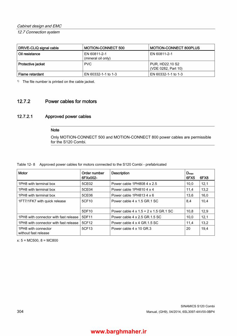
Cabinet design and EMC 12.7 Connection system
SINAMICS S120 Combi 304 Manual, (GH9), 04/2014, 6SL3097-4AV00-0BP4
DRIVE-CLiQ signal cable MOTION-CONNECT 500 MOTION-CONNECT 800PLUS Oil resistance EN 60811-2-1
(mineral oil only) EN 60811-2-1
Protective jacket PVC PUR, HD22.10 S2 (VDE 0282, Part 10)
Flame retardant EN 60332-1-1 to 1-3 EN 60332-1-1 to 1-3 1) The file number is printed on the cable jacket.
12.7.2 Power cables for motors
12.7.2.1 Approved power cables
Note
Only MOTION-CONNECT 500 and MOTION-CONNECT 800 power cables are permissible for the S120 Combi.
Table 12- 8 Approved power cables for motors connected to the S120 Combi - prefabricated
Motor Order number 6FXx002-
Description Dmax
6FX5 6FX8 1PH8 with terminal box 5CE02 Power cable 1PH808 4 x 2.5 10,0 12,1 1PH8 with terminal box 5CE04 Power cable 1PH810 4 x 4 11,4 13,2 1PH8 with terminal box 5CE06 Power cable 1PH813 4 x 6 13,6 16,0 1FT7/1FK7 with quick release 5CF10
Power cable 4 x 1.5 GR.1 SC 8,4 10,4
5DF10 Power cable 4 x 1.5 + 2 x 1.5 GR.1 SC 10,8 12,9 1PH8 with connector with fast release 5DF11 Power cable 4 x 2.5 GR.1.5 SC 10,0 12,1 1PH8 with connector with fast release 5CF12 Power cable 4 x 4 GR.1.5 SC 11,4 13,2 1PH8 with connector without fast release
5CF13 Power cable 4 x 10 GR.3 20 19,4
x: 5 = MC500, 8 = MC800
www.barghmaher.ir
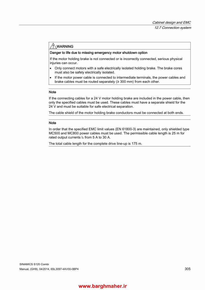
Cabinet design and EMC 12.7 Connection system
SINAMICS S120 Combi Manual, (GH9), 04/2014, 6SL3097-4AV00-0BP4 305
WARNING
Danger to life due to missing emergency motor shutdown option
If the motor holding brake is not connected or is incorrectly connected, serious physical injuries can occur. • Only connect motors with a safe electrically isolated holding brake. The brake cores
must also be safely electrically isolated. • If the motor power cable is connected to intermediate terminals, the power cables and
brake cables must be routed separately (≥ 300 mm) from each other.
Note
If the connecting cables for a 24 V motor holding brake are included in the power cable, then only the specified cables must be used. These cables must have a separate shield for the 24 V and must be suitable for safe electrical separation.
The cable shield of the motor holding brake conductors must be connected at both ends.
Note
In order that the specified EMC limit values (EN 61800-3) are maintained, only shielded type MC500 and MC800 power cables must be used. The permissible cable length is 25 m for rated output currents In from 5 A to 30 A.
The total cable length for the complete drive line-up is 175 m.
www.barghmaher.ir
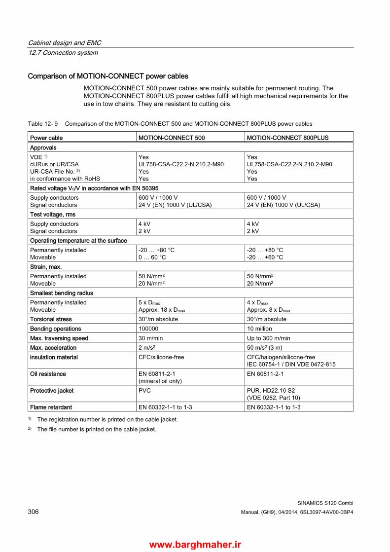
Cabinet design and EMC 12.7 Connection system
SINAMICS S120 Combi 306 Manual, (GH9), 04/2014, 6SL3097-4AV00-0BP4
Comparison of MOTION-CONNECT power cables MOTION-CONNECT 500 power cables are mainly suitable for permanent routing. The MOTION-CONNECT 800PLUS power cables fulfill all high mechanical requirements for the use in tow chains. They are resistant to cutting oils.
Table 12- 9 Comparison of the MOTION-CONNECT 500 and MOTION-CONNECT 800PLUS power cables
Power cable MOTION-CONNECT 500 MOTION-CONNECT 800PLUS Approvals VDE 1) cURus or UR/CSA UR-CSA File No. 2) in conformance with RoHS
Yes UL758-CSA-C22.2-N.210.2-M90 Yes Yes
Yes UL758-CSA-C22.2-N.210.2-M90 Yes Yes
Rated voltage V0/V in accordance with EN 50395 Supply conductors Signal conductors
600 V / 1000 V 24 V (EN) 1000 V (UL/CSA)
600 V / 1000 V 24 V (EN) 1000 V (UL/CSA)
Test voltage, rms Supply conductors Signal conductors
4 kV 2 kV
4 kV 2 kV
Operating temperature at the surface Permanently installed Moveable
-20 … +80 °C 0 … 60 °C
-20 … +80 °C -20 … +60 °C
Strain, max. Permanently installed Moveable
50 N/mm2
20 N/mm2 50 N/mm2
20 N/mm2 Smallest bending radius Permanently installed Moveable
5 x Dmax Approx. 18 x Dmax
4 x Dmax Approx. 8 x Dmax
Torsional stress 30°/m absolute 30°/m absolute Bending operations 100000 10 million Max. traversing speed 30 m/min Up to 300 m/min Max. acceleration 2 m/s2 50 m/s2 (3 m) insulation material CFC/silicone-free CFC/halogen/silicone-free
IEC 60754-1 / DIN VDE 0472-815 Oil resistance EN 60811-2-1
(mineral oil only) EN 60811-2-1
Protective jacket PVC PUR, HD22.10 S2 (VDE 0282, Part 10)
Flame retardant EN 60332-1-1 to 1-3 EN 60332-1-1 to 1-3 1) The registration number is printed on the cable jacket.
2) The file number is printed on the cable jacket.
www.barghmaher.ir

Cabinet design and EMC 12.7 Connection system
SINAMICS S120 Combi Manual, (GH9), 04/2014, 6SL3097-4AV00-0BP4 307
12.7.3 Current-carrying capacity and derating factors for power cables and signal cables
The current-carrying capacity of PVC/PUR-insulated copper cables is specified for routing types B1, B2 and C under continuous operating conditions in the table with reference to an ambient air temperature of 40 °C. For other ambient temperatures, the values must be corrected by the factors listed in the "Derating factors for deviating conditions" table.
Table 12- 10 Current-carrying capacity according to EN 60204-1 for 40 °C ambient temperature
Cross-section Current-carrying capacity, effective; AC 50/60 Hz or DC for routing type
mm2
B1 A
B2 A
C A
Electronics 0,20 – 4,3 4,4 0,50 – 7,5 7,5 0,75 – 9 9,5 Power 0,75 8,6 8,5 9,8 1,00 10,3 10,1 11,7 1,50 13,5 13,1 15,2 2,50 18,3 17,4 21 4 24 23 28 6 31 30 36 10 44 40 50 16 59 54 66 Installation types
B1 cables in conduits or installation ducts B2 multi-core cables in conduits or installation ducts C cables along walls/panels without conduits and installation ducts
Table 12- 11 Derating factors for deviating conditions
Ambient temperature [°C] Derating factor according to EN 60204-1 Table D1 30 1,15 35 1,08 40 1,00 45 0,91 50 0,82 55 0,71 60 0,58
www.barghmaher.ir

Cabinet design and EMC 12.7 Connection system
SINAMICS S120 Combi 308 Manual, (GH9), 04/2014, 6SL3097-4AV00-0BP4
Example for dimensioning a power cable Boundary conditions: Module: S120 Combi 4 axes Power Module with 20 kW infeed Rated input current at 400 VAC: 34 A (from the technical data) Ambient temperature: 45 °C Installation type: B2
Calculation/dimensioning: With installation type B2 and a rated input current of 34 AAC, from the table showing the current-carrying capacity, a cable cross-section of 10 mm2 is obtained.
With a derating factor of 0.91 for 45°C ambient temperature, the current-carrying capacity of the selected power cable decreases to 36.4 A.
Result: Under the given boundary conditions, a power cable with a cross-section of 10 mm2 can be used.
12.7.4 Connectable conductor cross-sections for spring-loaded terminals
Table 12- 12 Spring-loaded terminals
Type: Spring-loaded terminal 1 Connectable conductor cross-
sections Flexible 0.08 … 2.5 mm2
Stripped length 8 … 9 mm Tool Screwdriver 0.4 x 2.0 mm
www.barghmaher.ir
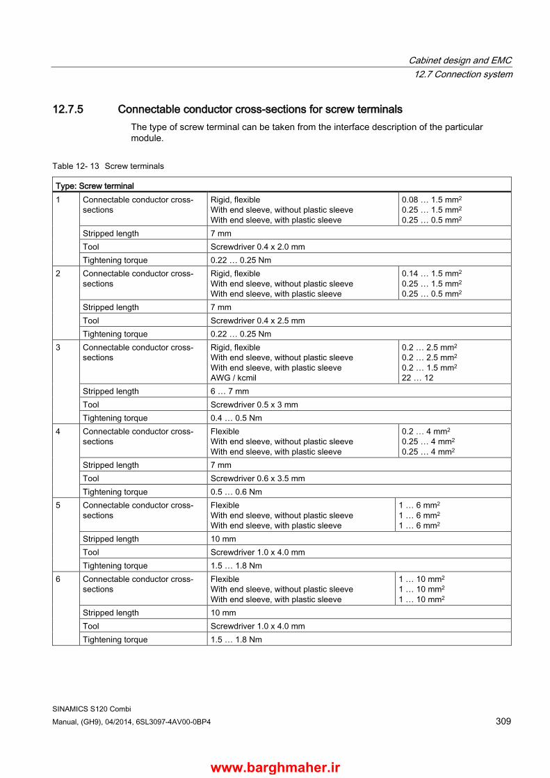
Cabinet design and EMC 12.7 Connection system
SINAMICS S120 Combi Manual, (GH9), 04/2014, 6SL3097-4AV00-0BP4 309
12.7.5 Connectable conductor cross-sections for screw terminals The type of screw terminal can be taken from the interface description of the particular module.
Table 12- 13 Screw terminals
Type: Screw terminal 1 Connectable conductor cross-
sections Rigid, flexible With end sleeve, without plastic sleeve With end sleeve, with plastic sleeve
0.08 … 1.5 mm2
0.25 … 1.5 mm2
0.25 … 0.5 mm2 Stripped length 7 mm Tool Screwdriver 0.4 x 2.0 mm Tightening torque 0.22 … 0.25 Nm
2 Connectable conductor cross-sections
Rigid, flexible With end sleeve, without plastic sleeve With end sleeve, with plastic sleeve
0.14 … 1.5 mm2
0.25 … 1.5 mm2
0.25 … 0.5 mm2 Stripped length 7 mm Tool Screwdriver 0.4 x 2.5 mm Tightening torque 0.22 … 0.25 Nm
3 Connectable conductor cross-sections
Rigid, flexible With end sleeve, without plastic sleeve With end sleeve, with plastic sleeve AWG / kcmil
0.2 … 2.5 mm2
0.2 … 2.5 mm2
0.2 … 1.5 mm2
22 … 12 Stripped length 6 … 7 mm Tool Screwdriver 0.5 x 3 mm Tightening torque 0.4 … 0.5 Nm
4 Connectable conductor cross-sections
Flexible With end sleeve, without plastic sleeve With end sleeve, with plastic sleeve
0.2 … 4 mm2
0.25 … 4 mm2
0.25 … 4 mm2 Stripped length 7 mm Tool Screwdriver 0.6 x 3.5 mm Tightening torque 0.5 … 0.6 Nm
5 Connectable conductor cross-sections
Flexible With end sleeve, without plastic sleeve With end sleeve, with plastic sleeve
1 … 6 mm2 1 … 6 mm2
1 … 6 mm2 Stripped length 10 mm Tool Screwdriver 1.0 x 4.0 mm Tightening torque 1.5 … 1.8 Nm
6 Connectable conductor cross-sections
Flexible With end sleeve, without plastic sleeve With end sleeve, with plastic sleeve
1 … 10 mm2 1 … 10 mm2
1 … 10 mm2 Stripped length 10 mm Tool Screwdriver 1.0 x 4.0 mm Tightening torque 1.5 … 1.8 Nm
www.barghmaher.ir

Cabinet design and EMC 12.7 Connection system
SINAMICS S120 Combi 310 Manual, (GH9), 04/2014, 6SL3097-4AV00-0BP4
Type: Screw terminal 7 Connectable conductor cross-
sections Flexible With end sleeve, without plastic sleeve With end sleeve, with plastic sleeve
1.5 … 16 mm2 1.5 … 16 mm2
1.5 … 16 mm2 Stripped length 11 mm Tool Screwdriver 1.0 x 4.0 mm Tightening torque 1.5 … 1.8 Nm
www.barghmaher.ir
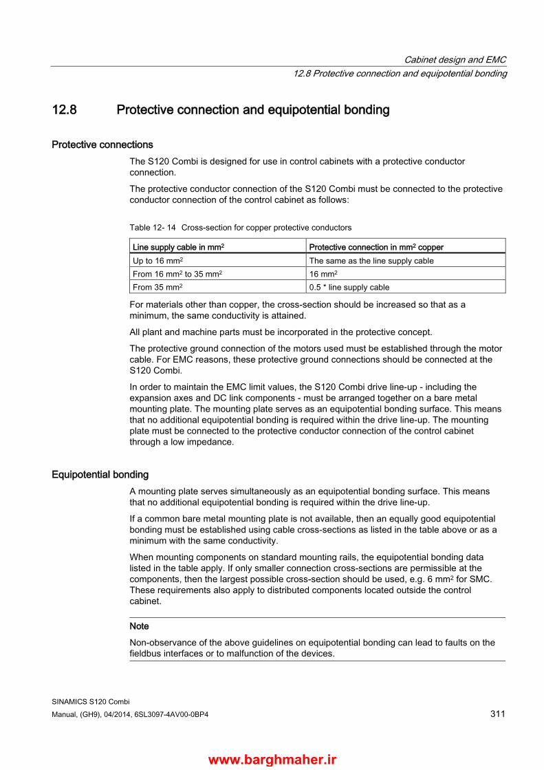
Cabinet design and EMC 12.8 Protective connection and equipotential bonding
SINAMICS S120 Combi Manual, (GH9), 04/2014, 6SL3097-4AV00-0BP4 311
12.8 Protective connection and equipotential bonding
Protective connections The S120 Combi is designed for use in control cabinets with a protective conductor connection.
The protective conductor connection of the S120 Combi must be connected to the protective conductor connection of the control cabinet as follows:
Table 12- 14 Cross-section for copper protective conductors
Line supply cable in mm2 Protective connection in mm2 copper Up to 16 mm2 The same as the line supply cable From 16 mm2 to 35 mm2 16 mm2 From 35 mm2 0.5 * line supply cable
For materials other than copper, the cross-section should be increased so that as a minimum, the same conductivity is attained.
All plant and machine parts must be incorporated in the protective concept.
The protective ground connection of the motors used must be established through the motor cable. For EMC reasons, these protective ground connections should be connected at the S120 Combi.
In order to maintain the EMC limit values, the S120 Combi drive line-up - including the expansion axes and DC link components - must be arranged together on a bare metal mounting plate. The mounting plate serves as an equipotential bonding surface. This means that no additional equipotential bonding is required within the drive line-up. The mounting plate must be connected to the protective conductor connection of the control cabinet through a low impedance.
Equipotential bonding A mounting plate serves simultaneously as an equipotential bonding surface. This means that no additional equipotential bonding is required within the drive line-up.
If a common bare metal mounting plate is not available, then an equally good equipotential bonding must be established using cable cross-sections as listed in the table above or as a minimum with the same conductivity.
When mounting components on standard mounting rails, the equipotential bonding data listed in the table apply. If only smaller connection cross-sections are permissible at the components, then the largest possible cross-section should be used, e.g. 6 mm2 for SMC. These requirements also apply to distributed components located outside the control cabinet.
Note
Non-observance of the above guidelines on equipotential bonding can lead to faults on the fieldbus interfaces or to malfunction of the devices.
www.barghmaher.ir
Cabinet design and EMC 12.9 Note on control cabinet cooling
SINAMICS S120 Combi 312 Manual, (GH9), 04/2014, 6SL3097-4AV00-0BP4
12.9 Note on control cabinet cooling
12.9.1 General information The cabinet can be cooled, among others, by using:
● Filter fans
● Heat exchangers
● Refrigerators
● External air cooling
The decision in favor of one of these methods will depend on the prevailing ambient conditions and the cooling power required.
The air routing inside the control cabinet and the cooling clearances specified here, must be carefully observed. Other components or cables must not be installed/routed in these areas.
NOTICE
Reduced service life due to non-compliance with the installation guidelines
If you do not observe the guidelines for installing SINAMICS equipment in the cabinet, this can reduce the service life of the equipment and result in premature component failure. • Always comply with the installation guidelines for SINAMICS devices.
You must take into account the following specifications when installing a SINAMICS drive line-up:
● Ventilation clearance
● Wiring and cabling
● Air guidance, air-conditioner
www.barghmaher.ir
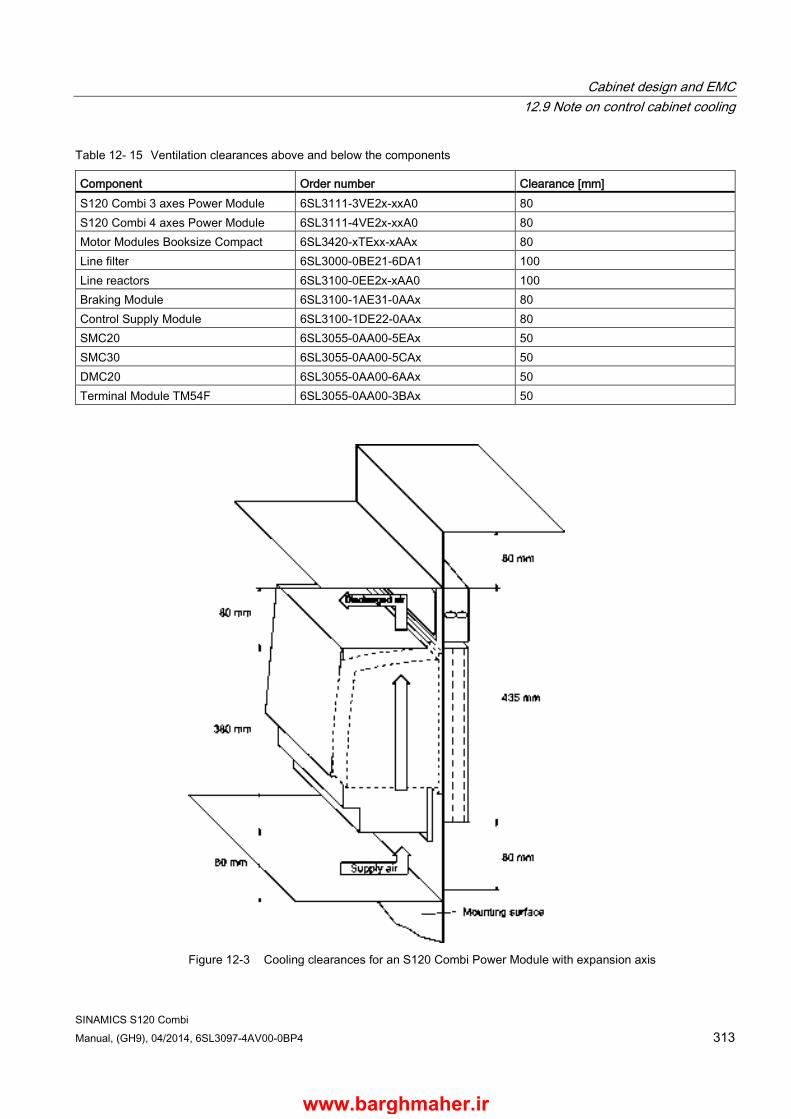
Cabinet design and EMC 12.9 Note on control cabinet cooling
SINAMICS S120 Combi Manual, (GH9), 04/2014, 6SL3097-4AV00-0BP4 313
Table 12- 15 Ventilation clearances above and below the components
Component Order number Clearance [mm] S120 Combi 3 axes Power Module 6SL3111-3VE2x-xxA0 80 S120 Combi 4 axes Power Module 6SL3111-4VE2x-xxA0 80 Motor Modules Booksize Compact 6SL3420-xTExx-xAAx 80 Line filter 6SL3000-0BE21-6DA1 100 Line reactors 6SL3100-0EE2x-xAA0 100 Braking Module 6SL3100-1AE31-0AAx 80 Control Supply Module 6SL3100-1DE22-0AAx 80 SMC20 6SL3055-0AA00-5EAx 50 SMC30 6SL3055-0AA00-5CAx 50 DMC20 6SL3055-0AA00-6AAx 50 Terminal Module TM54F 6SL3055-0AA00-3BAx 50
Figure 12-3 Cooling clearances for an S120 Combi Power Module with expansion axis
www.barghmaher.ir

Cabinet design and EMC 12.9 Note on control cabinet cooling
SINAMICS S120 Combi 314 Manual, (GH9), 04/2014, 6SL3097-4AV00-0BP4
Figure 12-4 Cooling clearances for Motor Modules Booksize Compact
www.barghmaher.ir

Cabinet design and EMC 12.9 Note on control cabinet cooling
SINAMICS S120 Combi Manual, (GH9), 04/2014, 6SL3097-4AV00-0BP4 315
Figure 12-5 Cooling clearances for modules mounted on standard rails (e.g. SMC, DMC)
12.9.2 Ventilation The S120 Combi is equipped with an internal fan to circulate the air inside the unit.
The cooling air must flow vertically through the external heat sink of the S120 Combi.
When using filter fans, heat exchangers, or air conditioners to cool the control cabinet, it must be ensured that the air is flowing in the correct direction. You must also ensure that the warm air can escape at the top. A ventilation clearance of at least 80 mm above and below must be observed.
NOTICE
Damage caused by cooling equipment
Damage to components can be caused by overheating or condensation. • Route the connected signal and power cables to the components in such a way that
they do not cover the ventilation slots. • Select the air guidance and arrangement of the cooling equipment in such a way that
cold air does not blow directly onto electronic equipment and as such no condensation can form on the components. If necessary, cabinet enclosure heating may have to be installed.
www.barghmaher.ir

Cabinet design and EMC 12.9 Note on control cabinet cooling
SINAMICS S120 Combi 316 Manual, (GH9), 04/2014, 6SL3097-4AV00-0BP4
Note
The distance between the discharge opening of the air condition equipment and the electronic equipment must be at least 200 mm.
Note
If the components are installed in a sealed control cabinet, an internal air cooling system must be installed in the control cabinet to circulate the air and prevent hot spots. It is best to install the fan above the components to optimize the air flow (suction).
Figure 12-6 Examples of cabinet ventilation
If air conditioners are used, the relative air humidity of the expelled air increases as the air in the air conditioner cools and may exceed the dew point. If the relative humidity of the air entering the SINAMICS equipment is over 80% for an extended period of time, the insulation in the equipment may fail to function properly due to electrochemical reactions (refer to Section System overview (Page 27)). Using air baffle plates, for example, you must ensure that the cold air expelled from the air conditioner mixes with warm air in the cabinet before it enters the unit. This reduces the relative air humidity to uncritical values.
www.barghmaher.ir

Cabinet design and EMC 12.9 Note on control cabinet cooling
SINAMICS S120 Combi Manual, (GH9), 04/2014, 6SL3097-4AV00-0BP4 317
12.9.3 Dimensioning Climate Control Equipment Cabinet manufacturers provide calculation programs for selecting climate control equipment. It is always necessary to know the power loss of the components and equipment installed in the cabinet.
The physical relationship is shown in the following example.
Calculating the thermal power to be dissipated: q = Q - k x A x ΔT
with q = thermal power that has to be dissipated using a cooling unit [W] Q = power loss [W] ∆T = difference between the room temperature and the temperature inside the cabinet [K] k = heat transfer coefficient, e.g. sheet-steel, painted 5.5 [W/(m2 * K)] A = free-standing cabinet surface area [m2]
Table 12- 16 Example, calculating the power loss of a drive configuration
Component Number Total power loss [W] (including electronic losses)
Total power loss [W]
SINUMERIK 828D 1 28 28 Line filter 1 16 16 Line reactor 1 98 98 S120 Combi 3 axes Power Module 20 kW
1 634 634
Motor Module 9 A 1 100,4 100,4 Motor Module 18 A 1 185,4 185,4 SMC 2 10 20 SITOP 20 1 53 53 Line contactor 1 12 12 Total: 1146,8
Assumption: free-standing control cabinet surface A = 5 m2
difference between the room temperature and the temperature inside the control cabinet ∆T = 10 K
q = 1146.8 W - 5.5 W / (m2 K) * 5 m2 * 10 K = 871.8 W
www.barghmaher.ir

Cabinet design and EMC 12.9 Note on control cabinet cooling
SINAMICS S120 Combi 318 Manual, (GH9), 04/2014, 6SL3097-4AV00-0BP4
12.9.4 Power loss of components in rated operation
12.9.4.1 General information The tables below provide an overview of the power loss of all components during rated operation. The characteristic values apply for the following conditions:
● Line supply voltage 400 V
● Pulse frequency of the Motor Modules 4 kHz (clock frequency of the spindle 4 kHz or 8 kHz)
● Operating components at their rated power
The total losses of the relevant components (S120 Combi, Motor Module) are calculated from the power loss and the corresponding losses from the electronics.
12.9.4.2 Power losses for SINUMERIK control systems, DC link components and supplementary system components
Table 12- 17 Overview of power losses at rated operation for SINUMERIK control systems, DC link components and supplementary system components
Unit Power loss SINUMERIK 828D W 28 SINUMERIK NCU 710.3 PN W 21 SMC20/30 W < 10 SME20/25 W < 4 TM54F W 4.5 Braking Module W 20 Control Supply Module Line DC link
W W
70 65
www.barghmaher.ir
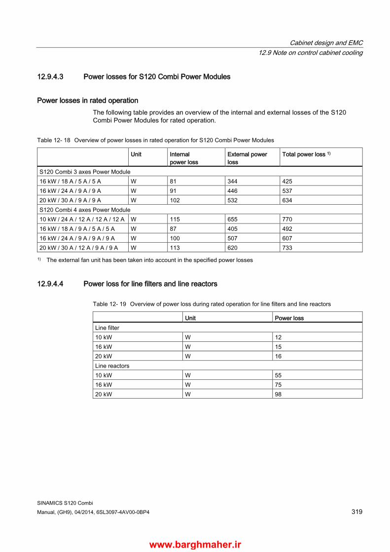
Cabinet design and EMC 12.9 Note on control cabinet cooling
SINAMICS S120 Combi Manual, (GH9), 04/2014, 6SL3097-4AV00-0BP4 319
12.9.4.3 Power losses for S120 Combi Power Modules
Power losses in rated operation The following table provides an overview of the internal and external losses of the S120 Combi Power Modules for rated operation.
Table 12- 18 Overview of power losses in rated operation for S120 Combi Power Modules
Unit Internal power loss
External power loss
Total power loss 1)
S120 Combi 3 axes Power Module 16 kW / 18 A / 5 A / 5 A W 81 344 425 16 kW / 24 A / 9 A / 9 A W 91 446 537 20 kW / 30 A / 9 A / 9 A W 102 532 634 S120 Combi 4 axes Power Module 10 kW / 24 A / 12 A / 12 A / 12 A W 115 655 770 16 kW / 18 A / 9 A / 5 A / 5 A W 87 405 492 16 kW / 24 A / 9 A / 9 A / 9 A W 100 507 607 20 kW / 30 A / 12 A / 9 A / 9 A W 113 620 733 1) The external fan unit has been taken into account in the specified power losses
12.9.4.4 Power loss for line filters and line reactors
Table 12- 19 Overview of power loss during rated operation for line filters and line reactors
Unit Power loss Line filter 10 kW W 12 16 kW W 15 20 kW W 16 Line reactors 10 kW W 55 16 kW W 75 20 kW W 98
www.barghmaher.ir
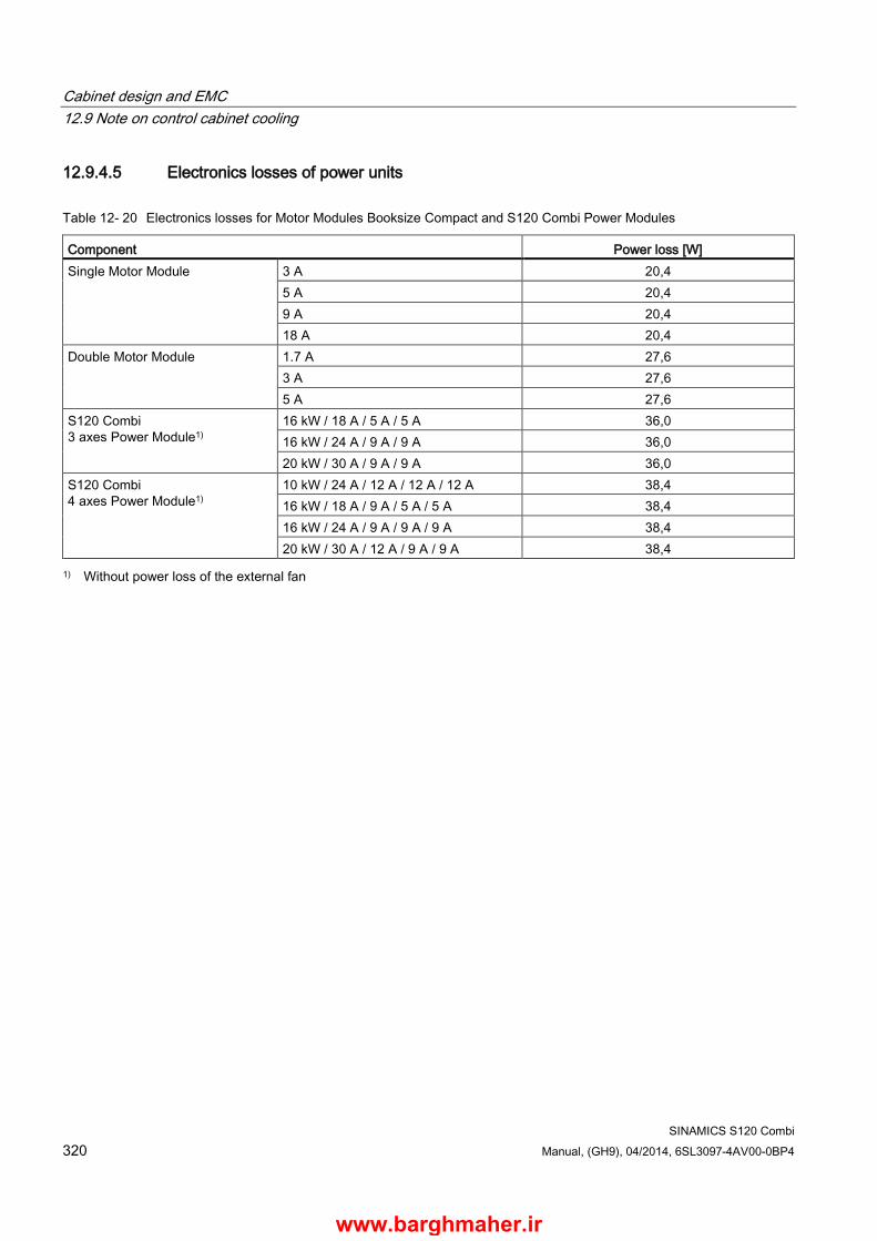
Cabinet design and EMC 12.9 Note on control cabinet cooling
SINAMICS S120 Combi 320 Manual, (GH9), 04/2014, 6SL3097-4AV00-0BP4
12.9.4.5 Electronics losses of power units
Table 12- 20 Electronics losses for Motor Modules Booksize Compact and S120 Combi Power Modules
Component Power loss [W] Single Motor Module 3 A 20,4
5 A 20,4 9 A 20,4 18 A 20,4
Double Motor Module 1.7 A 27,6 3 A 27,6 5 A 27,6
S120 Combi 3 axes Power Module1)
16 kW / 18 A / 5 A / 5 A 36,0 16 kW / 24 A / 9 A / 9 A 36,0 20 kW / 30 A / 9 A / 9 A 36,0
S120 Combi 4 axes Power Module1)
10 kW / 24 A / 12 A / 12 A / 12 A 38,4 16 kW / 18 A / 9 A / 5 A / 5 A 38,4 16 kW / 24 A / 9 A / 9 A / 9 A 38,4 20 kW / 30 A / 12 A / 9 A / 9 A 38,4
1) Without power loss of the external fan
www.barghmaher.ir

Cabinet design and EMC 12.9 Note on control cabinet cooling
SINAMICS S120 Combi Manual, (GH9), 04/2014, 6SL3097-4AV00-0BP4 321
12.9.4.6 Losses in partial-load operation
Losses in the partial-load range for the S120 Combi The losses of the S120 Combi in partial-load operation can be calculated using the following formula:
PV = a + b + IN1 x P1 + S1 x I1 + S2 x I2 + S3 x I3 + S4 x I4
With:
a: Electronics losses of the S120 Combi b: Electronics losses of the external fan unit (Order No.: 6SL3161-0EP00-0AA0) IN1, S1 - S4: Coefficients to calculate the power loss P1: Infeed power [kW] (LINE X1) I1: Spindle current [A] (SPINDLE X2) I2: Current of the 1st feed axis (servo X3) I3: Current of the 2nd feed axis (servo X4) I4: Current of the 3rd feed axis (servo X5)
Table 12- 21 Overview of the coefficients to calculate the total power loss PV in the partial-load range
Power Module a b IN1 S1 S2 S3 S4 3 axes Power Module 16 kW / 18 A 36 19,2 11,05 7,1 6,5 6,5 16 kW / 24 A 36 19,2 11,2 7,2 7,2 7,2 20 kW / 30 A 36 19,2 11,5 7,3 7,2 7,2 4-axis Power Module 10 kW / 24 A 38,4 19,2 9,1 14,3 / 7,21) 7,7 7,7 7,7 16 kW / 18 A 38,4 19,2 11,05 7,1 7,2 6,5 6,5 16 kW / 24 A 38,4 19,2 11,4 7,2 7,2 7,2 7,2 20 kW / 30 A 38,4 19,2 11,7 7,3 7,7 7,2 7,2 1) For a pulse frequency of 4 kHz / 8 kHz
Table 12- 22 Overview of the coefficients to calculate the power loss PV in the control cabinet for external cooling
Power Module a b IN1 S1 S2 S3 S4 3 axes Power Module 16 kW / 18 A 36 0 1,95 0,6 0,4 0,4 16 kW / 24 A 36 0 2,1 0,6 0,4 0,4 20 kW / 30 A 36 0 2,03 0,6 0,4 0,4 4-axis Power Module 10 kW / 24 A 38,4 0 3,3 1,2 / 0,61) 0,4 0,4 0,4 16 kW / 18 A 38,4 0 1,95 0,6 0,4 0,4 0,4 16 kW / 24 A 38,4 0 2,3 0,6 0,4 0,4 0,4 20 kW / 30 A 38,4 0 2,23 0,6 0,4 0,4 0,4 1) For a pulse frequency of 4 kHz / 8 kHz
www.barghmaher.ir
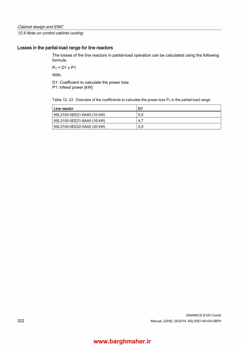
Cabinet design and EMC 12.9 Note on control cabinet cooling
SINAMICS S120 Combi 322 Manual, (GH9), 04/2014, 6SL3097-4AV00-0BP4
Losses in the partial-load range for line reactors The losses of the line reactors in partial-load operation can be calculated using the following formula:
PV = D1 x P1
With:
D1: Coefficient to calculate the power loss P1: Infeed power [kW]
Table 12- 23 Overview of the coefficients to calculate the power loss PV in the partial-load range
Line reactor D1 6SL3100-0EE21-6AA0 (10 kW) 5,5 6SL3100-0EE21-6AA0 (16 kW) 4,7 6SL3100-0EE22-0AA0 (20 kW) 4,9
www.barghmaher.ir
SINAMICS S120 Combi Manual, (GH9), 04/2014, 6SL3097-4AV00-0BP4 323
Service and maintenance 13 13.1 Technical Support
Technical support If you have any further questions, please call our hotline:
Technical Support Tel.: +49 (0) 180 5050 – 222 Fax: +49 (0) 180 5050 – 223 E-mail: [email protected]
If you have any queries (suggestions, corrections) in relation to this documentation, please fax or e-mail us:
Fax: +49 (0) 9131 98 – 2176 E-mail: [email protected]
Internet Address
Up-to-date information about our products can be found on the Internet at the following address:
http://www.ad.siemens.de/mc
www.barghmaher.ir
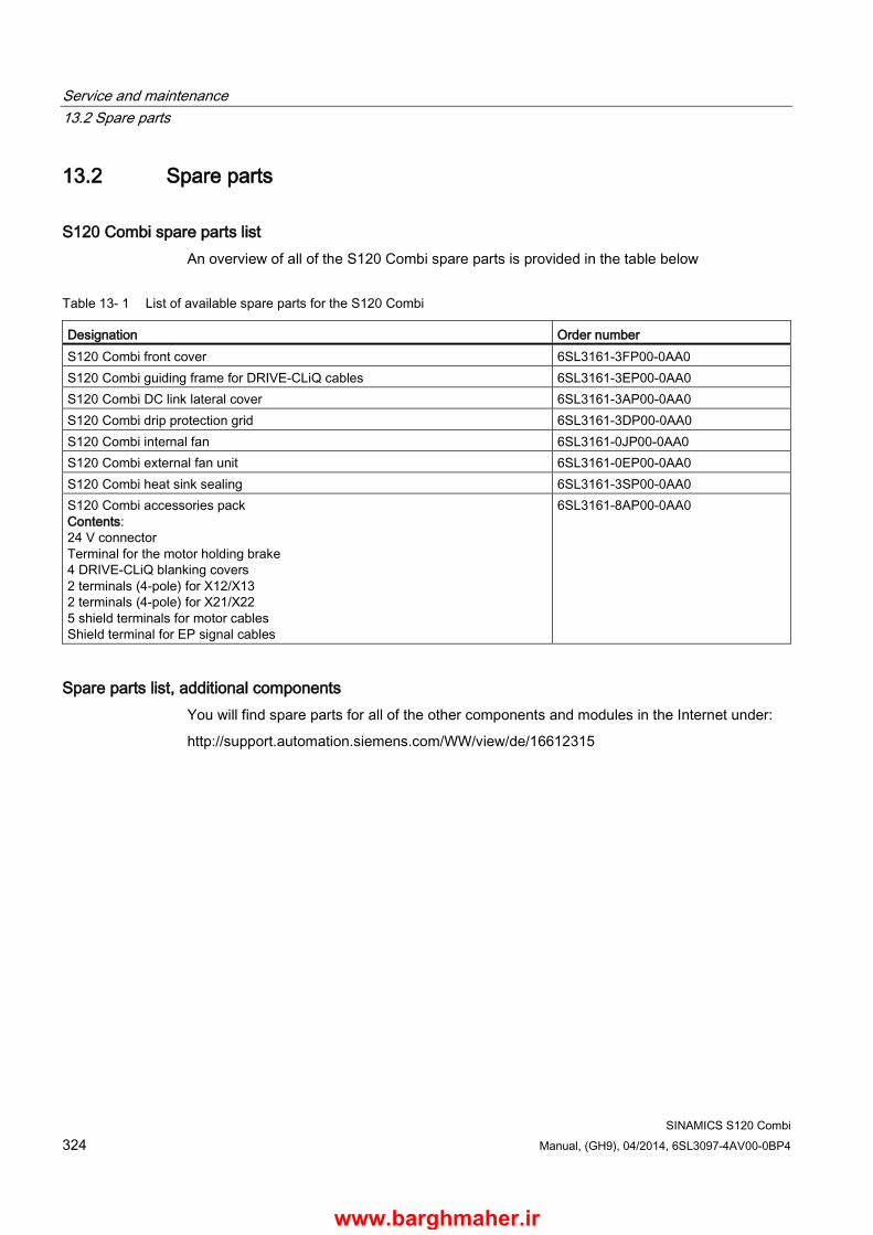
Service and maintenance 13.2 Spare parts
SINAMICS S120 Combi 324 Manual, (GH9), 04/2014, 6SL3097-4AV00-0BP4
13.2 Spare parts
S120 Combi spare parts list An overview of all of the S120 Combi spare parts is provided in the table below
Table 13- 1 List of available spare parts for the S120 Combi
Designation Order number S120 Combi front cover 6SL3161-3FP00-0AA0 S120 Combi guiding frame for DRIVE-CLiQ cables 6SL3161-3EP00-0AA0 S120 Combi DC link lateral cover 6SL3161-3AP00-0AA0 S120 Combi drip protection grid 6SL3161-3DP00-0AA0 S120 Combi internal fan 6SL3161-0JP00-0AA0 S120 Combi external fan unit 6SL3161-0EP00-0AA0 S120 Combi heat sink sealing 6SL3161-3SP00-0AA0 S120 Combi accessories pack Contents: 24 V connector Terminal for the motor holding brake 4 DRIVE-CLiQ blanking covers 2 terminals (4-pole) for X12/X13 2 terminals (4-pole) for X21/X22 5 shield terminals for motor cables Shield terminal for EP signal cables
6SL3161-8AP00-0AA0
Spare parts list, additional components You will find spare parts for all of the other components and modules in the Internet under:
http://support.automation.siemens.com/WW/view/de/16612315
www.barghmaher.ir

Service and maintenance 13.3 Replacing the fan
SINAMICS S120 Combi Manual, (GH9), 04/2014, 6SL3097-4AV00-0BP4 325
13.3 Replacing the fan
13.3.1 Safety instructions when replacing a fan
WARNING
Danger to life if the fundamental safety instructions and remaining risks are not carefully observed
If the fundamental safety instructions and remaining risks in Chapter 1 (Page 19) are not observed, accidents involving severe injuries or death may occur. • Adhere to the fundamental safety instructions. • When assessing the risk, take into account residual risks.
DANGER
Danger to life from electric shock due to applied voltage or residual charge
Switch off the power supply (400 V AC) before replacing the fan.
A hazardous voltage is still present for up to 5 minutes after the power supply has been switched off.
Contact with live parts can result in death or serious injury. • Remove the device cover or the fan cover only after 5 minutes have elapsed. • Check for zero voltage before removing the component.
WARNING
Danger to life when live parts are touched during fan replacement
Contact with live parts while the fan is being replaced can result in death or serious injury. • When removing the fan, you must observe the ESD regulations. • Assign qualified personnel to install spare parts.
www.barghmaher.ir
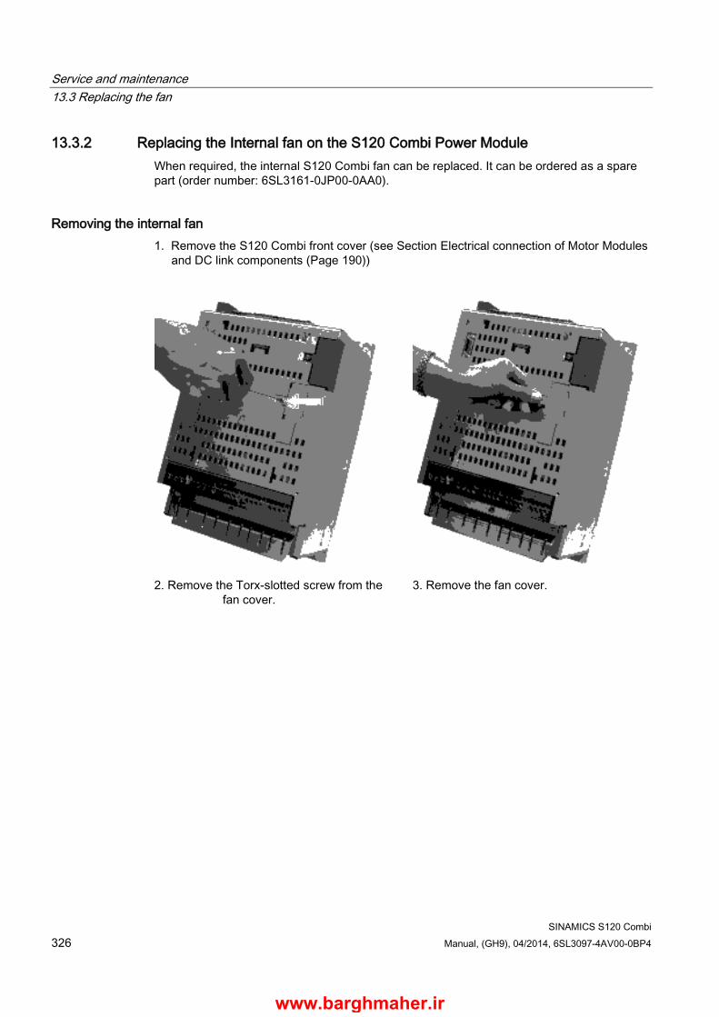
Service and maintenance 13.3 Replacing the fan
SINAMICS S120 Combi 326 Manual, (GH9), 04/2014, 6SL3097-4AV00-0BP4
13.3.2 Replacing the Internal fan on the S120 Combi Power Module When required, the internal S120 Combi fan can be replaced. It can be ordered as a spare part (order number: 6SL3161-0JP00-0AA0).
Removing the internal fan 1. Remove the S120 Combi front cover (see Section Electrical connection of Motor Modules
and DC link components (Page 190))
2. Remove the Torx-slotted screw from the
fan cover.
3. Remove the fan cover.
www.barghmaher.ir
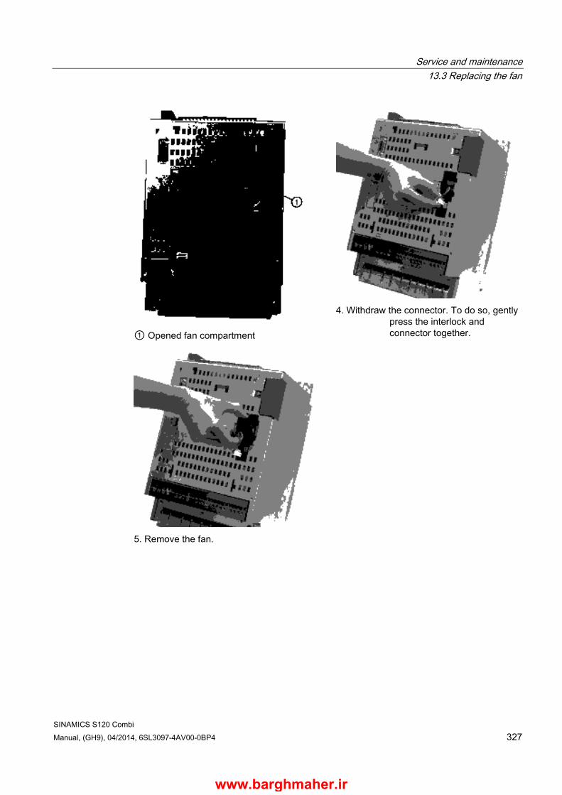
Service and maintenance 13.3 Replacing the fan
SINAMICS S120 Combi Manual, (GH9), 04/2014, 6SL3097-4AV00-0BP4 327
① Opened fan compartment
4. Withdraw the connector. To do so, gently
press the interlock and connector together.
5. Remove the fan.
www.barghmaher.ir

Service and maintenance 13.3 Replacing the fan
SINAMICS S120 Combi 328 Manual, (GH9), 04/2014, 6SL3097-4AV00-0BP4
Installing the internal fan 1. Before installing the fan, please note the airflow direction. The arrows on the fan must
match the diagram shown below.
Figure 13-1 Arrows on the fan for the air flow direction
2. Install the fan. The connecting cables must not be crushed.
3. Connect the fan connection, until this audibly clicks into place.
4. Close the fan cover.
5. Attach the fan cover using the Torx-slotted screw.
6. Mount the front cover and attach this using the Torx-slotted screws from the front.
www.barghmaher.ir

Service and maintenance 13.3 Replacing the fan
SINAMICS S120 Combi Manual, (GH9), 04/2014, 6SL3097-4AV00-0BP4 329
13.3.3 Replacing the fan on the Motor Modules Booksize Compact
Removing the fan
Size 50 mm Size 75 mm • Remove the Motor Module from the drive line-up.
• Remove the fan cover at the lower side of the Motor Module by releasing the snap hooks.
• Carefully withdraw the fan.
www.barghmaher.ir

Service and maintenance 13.3 Replacing the fan
SINAMICS S120 Combi 330 Manual, (GH9), 04/2014, 6SL3097-4AV00-0BP4
• Release the connector and remove the connecting cable.
www.barghmaher.ir
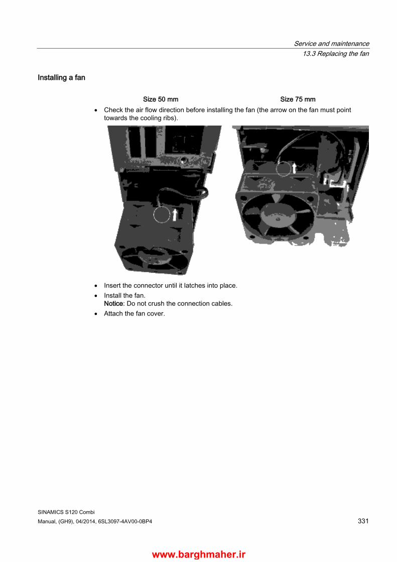
Service and maintenance 13.3 Replacing the fan
SINAMICS S120 Combi Manual, (GH9), 04/2014, 6SL3097-4AV00-0BP4 331
Installing a fan
Size 50 mm Size 75 mm • Check the air flow direction before installing the fan (the arrow on the fan must point
towards the cooling ribs).
• Insert the connector until it latches into place. • Install the fan.
Notice: Do not crush the connection cables. • Attach the fan cover.
www.barghmaher.ir
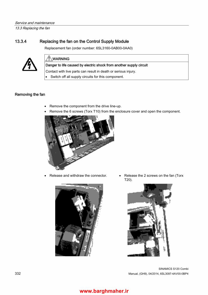
Service and maintenance 13.3 Replacing the fan
SINAMICS S120 Combi 332 Manual, (GH9), 04/2014, 6SL3097-4AV00-0BP4
13.3.4 Replacing the fan on the Control Supply Module Replacement fan (order number: 6SL3160-0AB00-0AA0)
WARNING
Danger to life caused by electric shock from another supply circuit
Contact with live parts can result in death or serious injury. • Switch off all supply circuits for this component.
Removing the fan • Remove the component from the drive line-up. • Remove the 6 screws (Torx T10) from the enclosure cover and open the component.
• Release and withdraw the connector. • Release the 2 screws on the fan (Torx T20).
www.barghmaher.ir

Service and maintenance 13.3 Replacing the fan
SINAMICS S120 Combi Manual, (GH9), 04/2014, 6SL3097-4AV00-0BP4 333
• Remove the fan.
Installing a fan 1. Check the air flow direction before installing the fan (the arrow on the fan must point
towards the cooling ribs).
2. Insert the connector until it latches into place.
3. Screw the 2 screws on the fan (Torx T20). The tightening torque is 1.2 Nm.
4. Close the enclosure cover and screw this with 6 screws (Torx T10). The tightening torque is 0.8 Nm.
www.barghmaher.ir
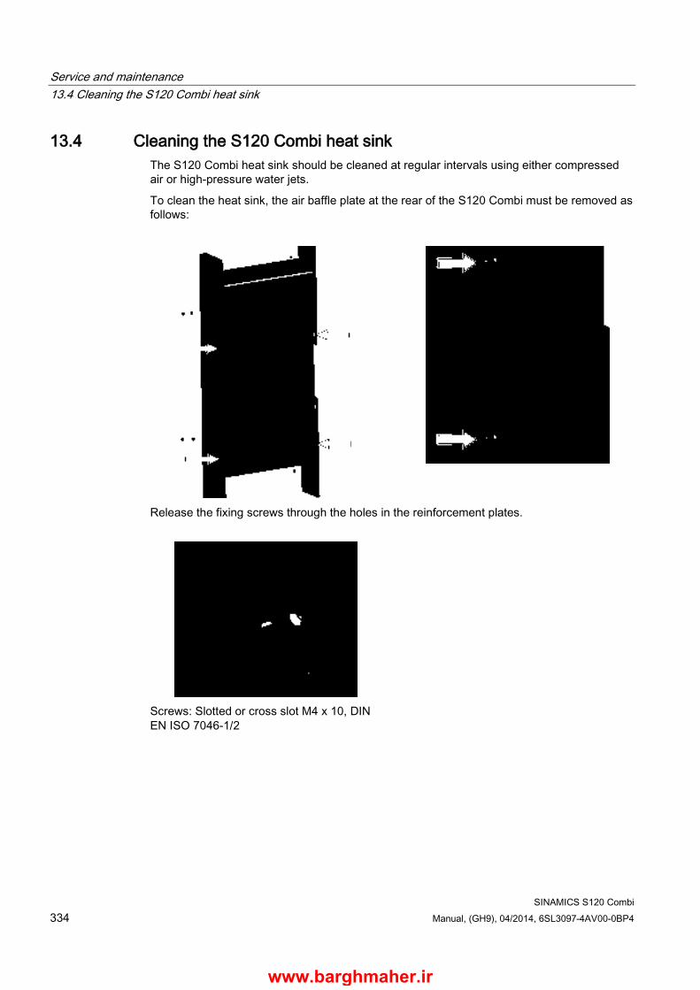
Service and maintenance 13.4 Cleaning the S120 Combi heat sink
SINAMICS S120 Combi 334 Manual, (GH9), 04/2014, 6SL3097-4AV00-0BP4
13.4 Cleaning the S120 Combi heat sink The S120 Combi heat sink should be cleaned at regular intervals using either compressed air or high-pressure water jets.
To clean the heat sink, the air baffle plate at the rear of the S120 Combi must be removed as follows:
Release the fixing screws through the holes in the reinforcement plates.
Screws: Slotted or cross slot M4 x 10, DIN EN ISO 7046-1/2
www.barghmaher.ir
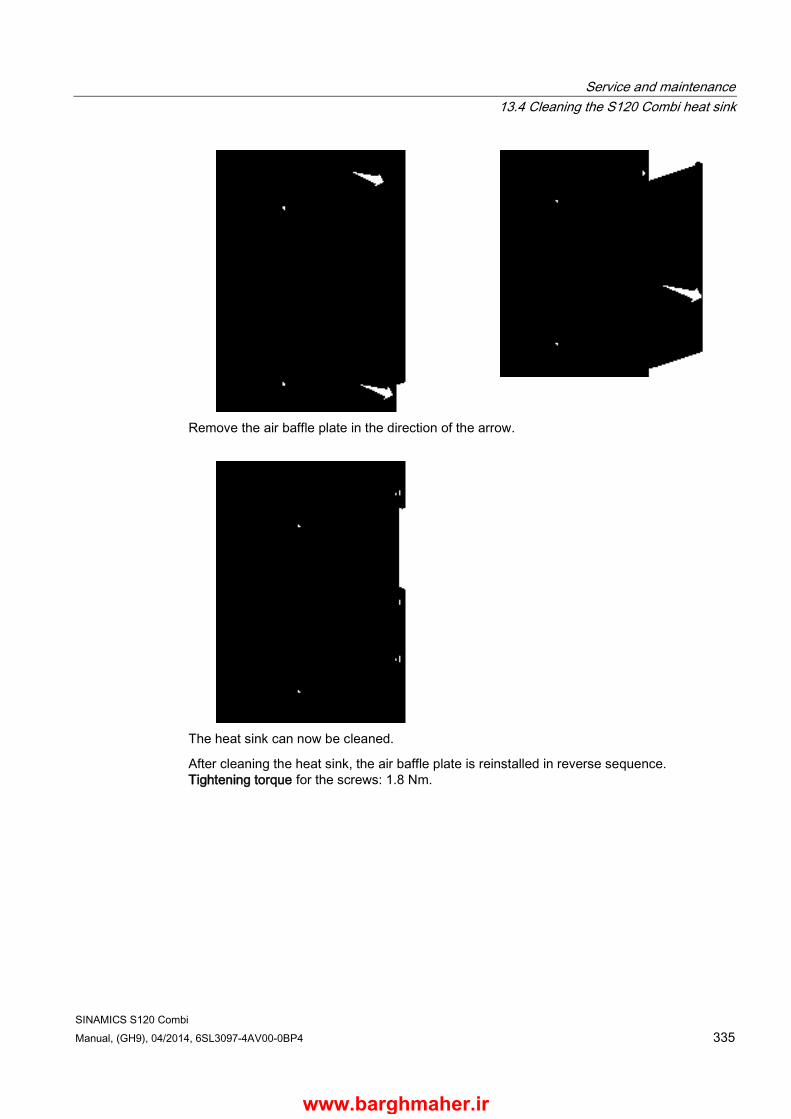
Service and maintenance 13.4 Cleaning the S120 Combi heat sink
SINAMICS S120 Combi Manual, (GH9), 04/2014, 6SL3097-4AV00-0BP4 335
Remove the air baffle plate in the direction of the arrow.
The heat sink can now be cleaned.
After cleaning the heat sink, the air baffle plate is reinstalled in reverse sequence. Tightening torque for the screws: 1.8 Nm.
www.barghmaher.ir
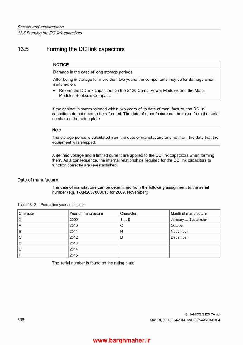
Service and maintenance 13.5 Forming the DC link capacitors
SINAMICS S120 Combi 336 Manual, (GH9), 04/2014, 6SL3097-4AV00-0BP4
13.5 Forming the DC link capacitors
NOTICE
Damage in the case of long storage periods
After being in storage for more than two years, the components may suffer damage when switched on. • Reform the DC link capacitors on the S120 Combi Power Modules and the Motor
Modules Booksize Compact.
If the cabinet is commissioned within two years of its date of manufacture, the DC link capacitors do not need to be reformed. The date of manufacture can be taken from the serial number on the rating plate.
Note
The storage period is calculated from the date of manufacture and not from the date that the equipment was shipped.
A defined voltage and a limited current are applied to the DC link capacitors when forming them. As a consequence, the internal relationships required for the DC link capacitors to function correctly are re-established.
Date of manufacture The date of manufacture can be determined from the following assignment to the serial number (e.g. T-XN2067000015 for 2009, November):
Table 13- 2 Production year and month
Character Year of manufacture Character Month of manufacture X 2009 1 … 9 January ... September A 2010 O October B 2011 N November C 2012 D December D 2013 E 2014 F 2015
The serial number is found on the rating plate.
www.barghmaher.ir
Service and maintenance 13.5 Forming the DC link capacitors
SINAMICS S120 Combi Manual, (GH9), 04/2014, 6SL3097-4AV00-0BP4 337
Forming circuit The S120 Combi Power Module has internal PTC resistors to pre-charge the DC link capacitors. The resistors can be used to form the DC link capacitors of the S120 Combi Module as well as the expansion axes (Motors Modules Booksize Compact).
During the forming process, it is not permissible for the S120 Combi Power Module to receive a switch-on command. Therefore, disconnect the 24 V power supply to the S120 Combi Power Module.
Procedure
S120 Combi Power Modules
1. Connect the S120 Combi Power Module with a line reactor to the line supply (see the connection example in Section Interface description (Page 71)).
2. Keep the module connected to the line supply for approx. 1 hour without issuing a switch-on command.
Expansion axis (Motor Module Booksize Compact)
1. Connect the expansion axis to be formed to the DC link of the S120 Combi Power Module.
2. Connect the S120 Combi Power Module with a line reactor to the line supply (see Section Connection examples (Page 87)).
3. Keep the S120 Combi Power Module and the expansion axis connected to the line supply for approx. 1 hour without issuing a switch-on command.
DANGER
Danger to life through electric shock due to the residual charge of the DC link capacitors
Due to the DC link capacitors, a hazardous voltage is present in the DC link for up to five minutes after the power supply has been switched off.
Contact with live parts can result in death or serious injury. • Do not open the protective cover of the DC link until five minutes have elapsed.
Ensure that you press the release catch when opening the protective cover for the DC link. A suitable tool (e.g. screwdriver or supplied release tool) must be used for this purpose.
• Only operate the S120 Combi with the DC link protective cover closed. • Do not continue to operate damaged components.
www.barghmaher.ir

Service and maintenance 13.6 Installing seals on the S120 Combi
SINAMICS S120 Combi 338 Manual, (GH9), 04/2014, 6SL3097-4AV00-0BP4
13.6 Installing seals on the S120 Combi
NOTICE
Material damage due to dust or spray water
If IP54 protection is not ensured, dust and spray water can result in damage. • Only operate the system with a functioning seal.
When required, the S120 Combi heat sink seal can be replaced.
An appropriate new seal must always be used when reassembling an S120 Combi Power Module.
The self-adhesive heat sink seal can be ordered as spare part (order number: 6SL3161-3SP00-0AA0).
Replacing the heat sink seal
Before reassembling, remove the previous seal and the remains of the seal at both the S120 Combi as well as at the control cabinet. The seal surfaces must be free of grease and dust. When removing an S120 Combi Power Module follow the assembly steps in Chapter Installation (Page 93) in the inverse sequence.
Figure 13-2 Installing the heat sink seal
www.barghmaher.ir

Service and maintenance 13.6 Installing seals on the S120 Combi
SINAMICS S120 Combi Manual, (GH9), 04/2014, 6SL3097-4AV00-0BP4 339
Glue the heat sink seal into the heat sink groove. When doing this, follow the outer edge of the groove.
Note
Do not stretch or compress the seal.
www.barghmaher.ir
Service and maintenance 13.7 Recycling and disposal
SINAMICS S120 Combi 340 Manual, (GH9), 04/2014, 6SL3097-4AV00-0BP4
13.7 Recycling and disposal Dispose of the product according to the applicable national regulations.
The products described in this Equipment Manual are extensively recyclable on account of the low-toxic composition of the materials used. To recycle and dispose of your old device in an environmentally friendly way, please contact a company that disposes of electronic waste.
www.barghmaher.ir
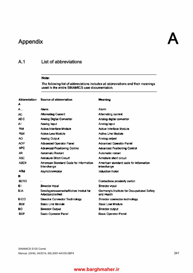
SINAMICS S120 Combi Manual, (GH9), 04/2014, 6SL3097-4AV00-0BP4 341
Appendix A A.1 List of abbreviations
www.barghmaher.ir
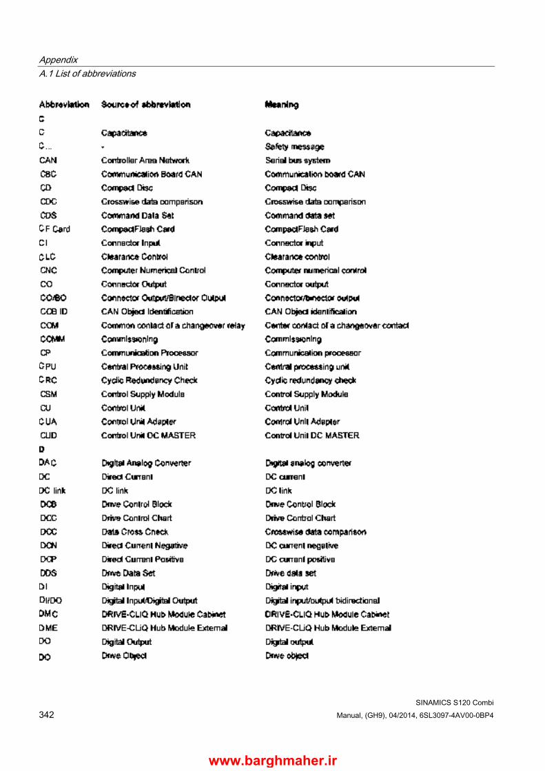
Appendix A.1 List of abbreviations
SINAMICS S120 Combi 342 Manual, (GH9), 04/2014, 6SL3097-4AV00-0BP4
www.barghmaher.ir

Appendix A.1 List of abbreviations
SINAMICS S120 Combi Manual, (GH9), 04/2014, 6SL3097-4AV00-0BP4 343
www.barghmaher.ir

Appendix A.1 List of abbreviations
SINAMICS S120 Combi 344 Manual, (GH9), 04/2014, 6SL3097-4AV00-0BP4
www.barghmaher.ir
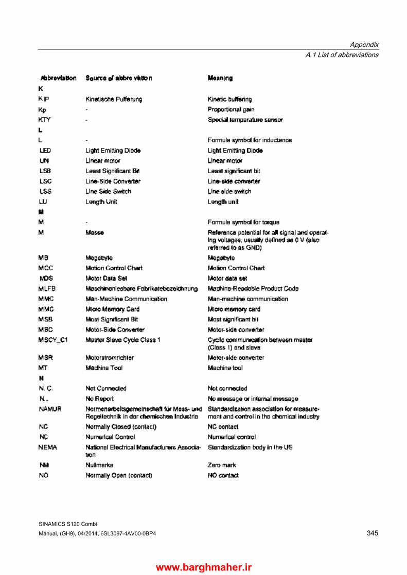
Appendix A.1 List of abbreviations
SINAMICS S120 Combi Manual, (GH9), 04/2014, 6SL3097-4AV00-0BP4 345
www.barghmaher.ir

Appendix A.1 List of abbreviations
SINAMICS S120 Combi 346 Manual, (GH9), 04/2014, 6SL3097-4AV00-0BP4
www.barghmaher.ir
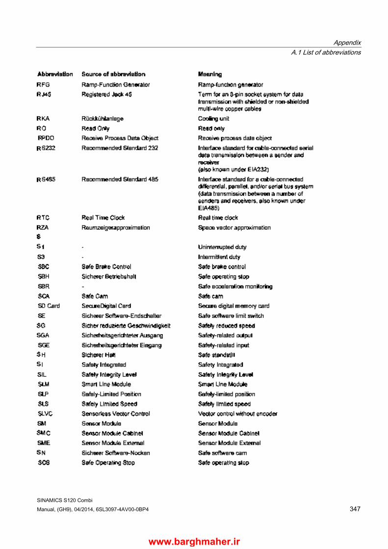
Appendix A.1 List of abbreviations
SINAMICS S120 Combi Manual, (GH9), 04/2014, 6SL3097-4AV00-0BP4 347
www.barghmaher.ir

Appendix A.1 List of abbreviations
SINAMICS S120 Combi 348 Manual, (GH9), 04/2014, 6SL3097-4AV00-0BP4
www.barghmaher.ir
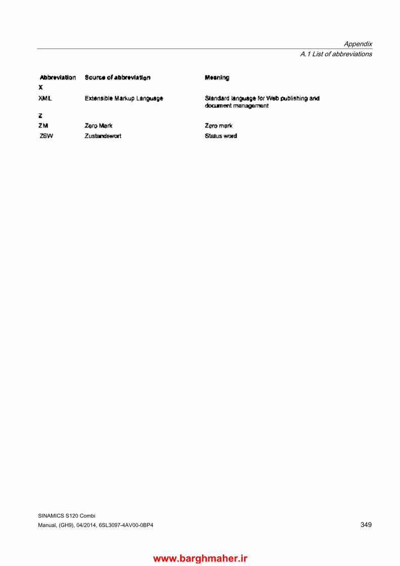
Appendix A.1 List of abbreviations
SINAMICS S120 Combi Manual, (GH9), 04/2014, 6SL3097-4AV00-0BP4 349
www.barghmaher.ir
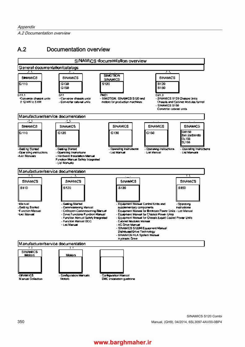
Appendix A.2 Documentation overview
SINAMICS S120 Combi 350 Manual, (GH9), 04/2014, 6SL3097-4AV00-0BP4
A.2 Documentation overview
www.barghmaher.ir
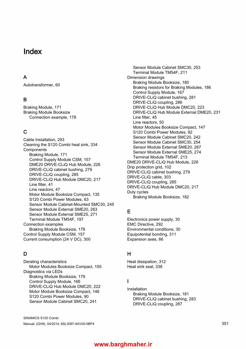
SINAMICS S120 Combi Manual, (GH9), 04/2014, 6SL3097-4AV00-0BP4 351
Index
A Autotransformer, 60
B Braking Module, 171 Braking Module Booksize
Connection example, 178
C Cable Installation, 293 Cleaning the S120 Combi heat sink, 334 Components
Braking Module, 171 Control Supply Module CSM, 157 DME20 DRIVE-CLiQ Hub Module, 226 DRIVE-CLiQ cabinet bushing, 279 DRIVE-CLiQ coupling, 285 DRIVE-CLiQ Hub Module DMC20, 217 Line filter, 41 Line reactors, 47 Motor Module Booksize Compact, 135 S120 Combi Power Modules, 63 Sensor Module Cabinet-Mounted SMC30, 245 Sensor Module External SME20, 263 Sensor Module External SME25, 271 Terminal Module TM54F, 197
Connection examples Braking Module Booksize, 178
Control Supply Module CSM, 157 Current consumption (24 V DC), 300
D Derating characteristics
Motor Modules Booksize Compact, 155 Diagnostics via LEDs
Braking Module Booksize, 179 Control Supply Module, 166 DRIVE-CLiQ Hub Module DMC20, 222 Motor Module Booksize Compact, 146 S120 Combi Power Modules, 90 Sensor Module Cabinet SMC20, 241
Sensor Module Cabinet SMC30, 253 Terminal Module TM54F, 211
Dimension drawings Braking Module Booksize, 180 Braking resistors for Braking Modules, 186 Control Supply Module, 167 DRIVE-CLiQ cabinet bushing, 281 DRIVE-CLiQ coupling, 286 DRIVE-CLiQ Hub Module DMC20, 223 DRIVE-CLiQ Hub Module External DME20, 231 Line filter, 45 Line reactors, 50 Motor Modules Booksize Compact, 147 S120 Combi Power Modules, 92 Sensor Module Cabinet SMC20, 242 Sensor Module Cabinet SMC30, 254 Sensor Module External SME20, 267 Sensor Module External SME25, 274 Terminal Module TM54F, 213
DME20 DRIVE-CLiQ Hub Module, 226 Drip protection grid, 102 DRIVE-CLiQ cabinet bushing, 279 DRIVE-CLiQ cable, 303 DRIVE-CLiQ coupling, 285 DRIVE-CLiQ Hub Module DMC20, 217 Duty cycles
Braking Module Booksize, 182
E Electronics power supply, 30 EMC Directive, 292 Environmental conditions, 30 Equipotential bonding, 311 Expansion axes, 66
H Heat dissipation, 312 Heat sink seal, 338
I Installation
Braking Module Booksize, 181 DRIVE-CLiQ cabinet bushing, 283 DRIVE-CLiQ coupling, 287
www.barghmaher.ir

Index
SINAMICS S120 Combi 352 Manual, (GH9), 04/2014, 6SL3097-4AV00-0BP4
DRIVE-CLiQ Hub Module DMC20, 224 Motor Module Booksize Compact, 150 S120 Combi Power Modules, 93 Sensor Module Cabinet, 243, 255 Sensor Module External SME20/SME25, 268, 275 Terminal Modules, 214
Interface descriptions Braking Module Booksize, 175 Control Supply Module, 160 DRIVE-CLiQ cabinet bushing, 280 DRIVE-CLiQ cabinet bushing M12, 280 DRIVE-CLiQ coupling, 286 DRIVE-CLiQ Hub Module DMC20, 219 DRIVE-CLiQ Hub Module External DME20, 227 Line filter, 44 Line reactors, 49 Motor Modules Booksize Compact, 139 S120 Combi 3 axes Power Module, 71 S120 Combi 4 axes Power Module, 73 Sensor Module Cabinet SMC20, 237 Sensor Module Cabinet SMC30, 246 Sensor Module External SME20, 264 Sensor Module External SME25, 271 Terminal Module TM54F, 199
Isolating transformer, 61
L LEDs
Braking Module Booksize, 179 Control Supply Module, 166 DRIVE-CLiQ Hub Module DMC20, 222 Motor Module Booksize Compact, 146 S120 Combi Power Modules, 90 Sensor Module Cabinet SMC20, 241 Sensor Module Cabinet SMC30, 253 Terminal Module TM54F, 211
Line connection, 35 Line connection voltage, 30 Line Connections, 53 Line disconnector, 36 Line filter, 41 Line frequency, 30 Line reactors, 47 Line supply types, 30
M MOTION-CONNECT cables
DRIVE-CLiQ signal cables, 303 Power cables, 304
Motor Module Booksize Compact, 135 Motors
Line connection, 54
O Overcurrent protection
Line side, 37 Solid-sate circuit, 299
P Power cables, 304 Power loss, 318 Power loss calculation, 317 Power Supply Units, 302 Product-specific safety instructions
Sensor Module Cabinet SMC20, 235 Protective conductor connection and shield support
Terminal Module TM54F, 215
R Rated duty cycles
Motor Modules Booksize Compact, 153 S120 Combi Power Modules, 120
Replacing the fan Control Supply Module CSM, 332 S120 Combi - internal fan, 326
Residual-current operated circuit breakers, 38
S S120 Combi Power Modules, 63 Safety instructions
Braking resistors, 185 DRIVE-CLiQ Hub Module DMC20, 218
Sensor Module Cabinet-Mounted SMC30, 245 Sensor Module External SME20, 263 Sensor Module External SME25, 271 Spare parts, 324 Specification of encoder systems and encoders
Sensor Module Cabinet SMC30, 84, 258 Storage, 30 System data, 30
T Technical data
Braking Module Booksize, 182
www.barghmaher.ir
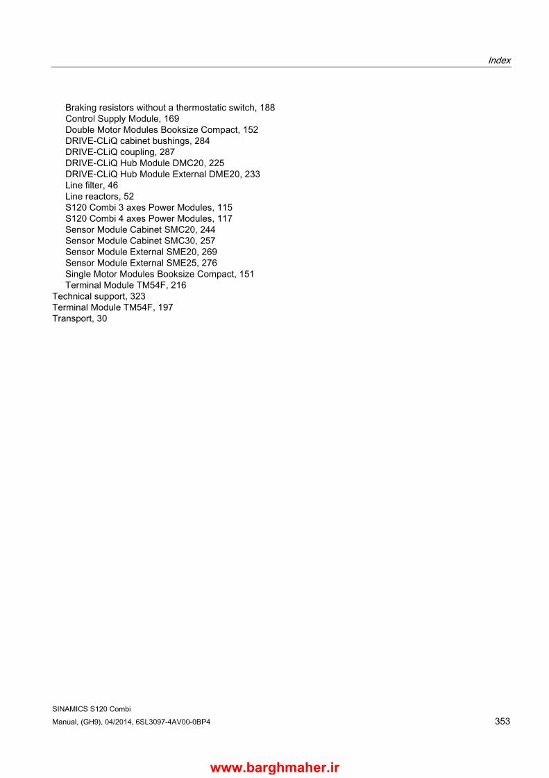
Index
SINAMICS S120 Combi Manual, (GH9), 04/2014, 6SL3097-4AV00-0BP4 353
Braking resistors without a thermostatic switch, 188 Control Supply Module, 169 Double Motor Modules Booksize Compact, 152 DRIVE-CLiQ cabinet bushings, 284 DRIVE-CLiQ coupling, 287 DRIVE-CLiQ Hub Module DMC20, 225 DRIVE-CLiQ Hub Module External DME20, 233 Line filter, 46 Line reactors, 52 S120 Combi 3 axes Power Modules, 115 S120 Combi 4 axes Power Modules, 117 Sensor Module Cabinet SMC20, 244 Sensor Module Cabinet SMC30, 257 Sensor Module External SME20, 269 Sensor Module External SME25, 276 Single Motor Modules Booksize Compact, 151 Terminal Module TM54F, 216
Technical support, 323 Terminal Module TM54F, 197 Transport, 30
www.barghmaher.ir

www.barghmaher.ir
Related Documents